Embed Size (px)
Citation preview
Service & Maintenance Manual
AC112 & CN268/328 Bus Air-Conditioning Units
CN268/328 & AC112
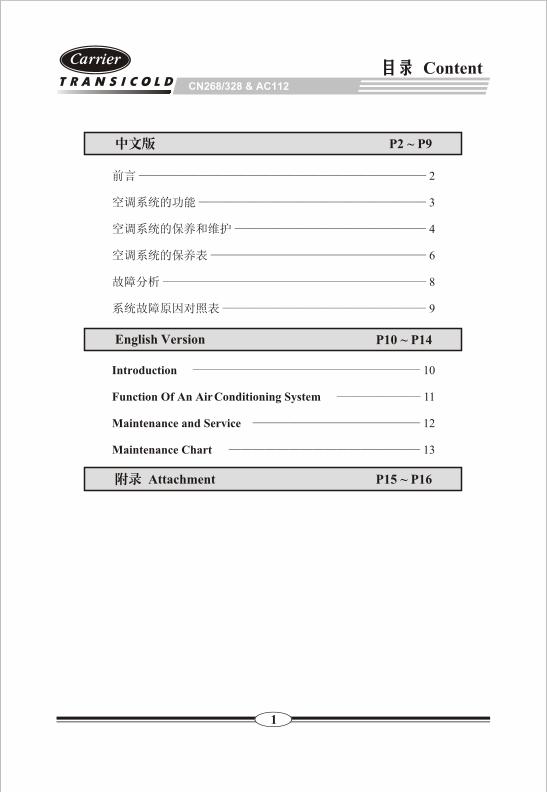
Content
Introduction Function Of An Air Conditioning System
Maintenance and Service
Maintenance Chart
2
8
9
3
4
6
English Version
Attachment
P2 ~ P9
P10 ~ P14
10
11
12
13
P15 ~ P16
1
CN268/328 & AC112
2
CN268/328 & AC112
3
-
/
4
30
24
( )
CN268/328 & AC112
5
200-300
CN268/328 & AC112
6
CN268/328 & AC112
50
1
2
3 V V
4
1500r/min 10 15
200
1
2
3
4
5
1
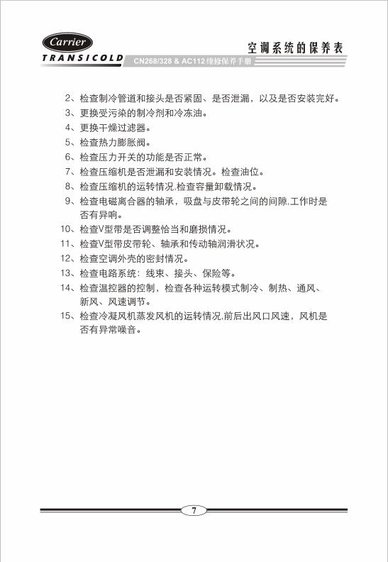
7
CN268/328 & AC112
2
3
4
5
6
7
8 ,
9 ,
10 V
11 V
12
13
14
15 ,
8
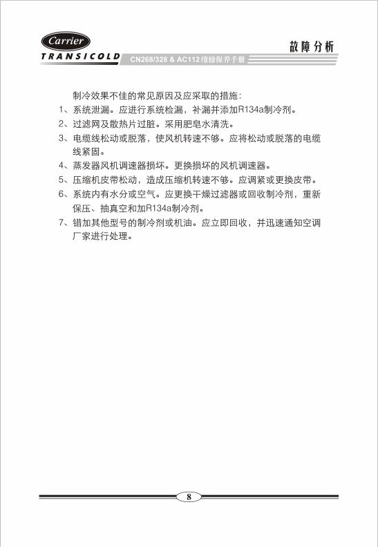
CN268/328 & AC112
1 R134a
2
3
4
5
6
R134a
7
9
CN268/328 & AC112
10
Operation & Maintenance Manual
Introduction
This guide has been prepared for the operator of the air conditioning unit. It
contains basic instructions for the daily operation of the air conditioning unit as
well as safety information, maintenance and service, the maintenance chart and
the inspection chart.
Your air conditioning unit has been engineered to provide long, trouble-free
performance when it is properly operated and maintained. The maintenance and
service outlined in this guide will help to minimize over-the-road-problems. The
maintenance chart and inspection chart will also help to control operating costs,
increase the unit's working life, and improve performance.
11
Operation & Maintenance Manual
Function Of An Air Conditioning System
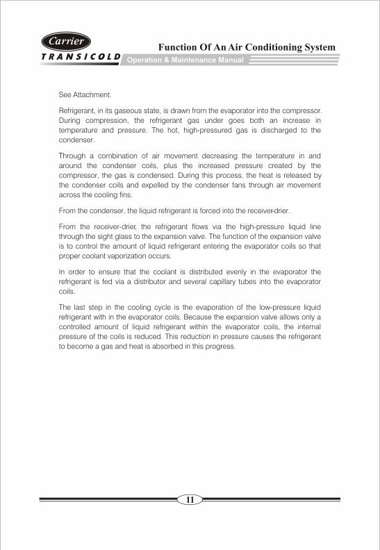
See Attachment.
Refrigerant, in its gaseous state, is drawn from the evaporator into the compressor.
During compression, the refrigerant gas under goes both an increase in
temperature and pressure. The hot, high-pressured gas is discharged to the
condenser.
Through a combination of air movement decreasing the temperature in and
around the condenser coils, plus the increased pressure created by the
compressor, the gas is condensed. During this process, the heat is released by
the condenser coils and expelled by the condenser fans through air movement
across the cooling fins.
From the condenser, the liquid refrigerant is forced into the receiver-drier.
From the receiver-drier, the refrigerant flows via the high-pressure liquid line
through the sight glass to the expansion valve. The function of the expansion valve
is to control the amount of liquid refrigerant entering the evaporator coils so that
proper coolant vaporization occurs.
In order to ensure that the coolant is distributed evenly in the evaporator the
refrigerant is fed via a distributor and several capillary tubes into the evaporator
coils.
The last step in the cooling cycle is the evaporation of the low-pressure liquid
refrigerant with in the evaporator coils. Because the expansion valve allows only a
controlled amount of liquid refrigerant within the evaporator coils, the internal
pressure of the coils is reduced. This reduction in pressure causes the refrigerant
to become a gas and heat is absorbed in this progress.
12
Operation & Maintenance Manual
Maintenance and Service
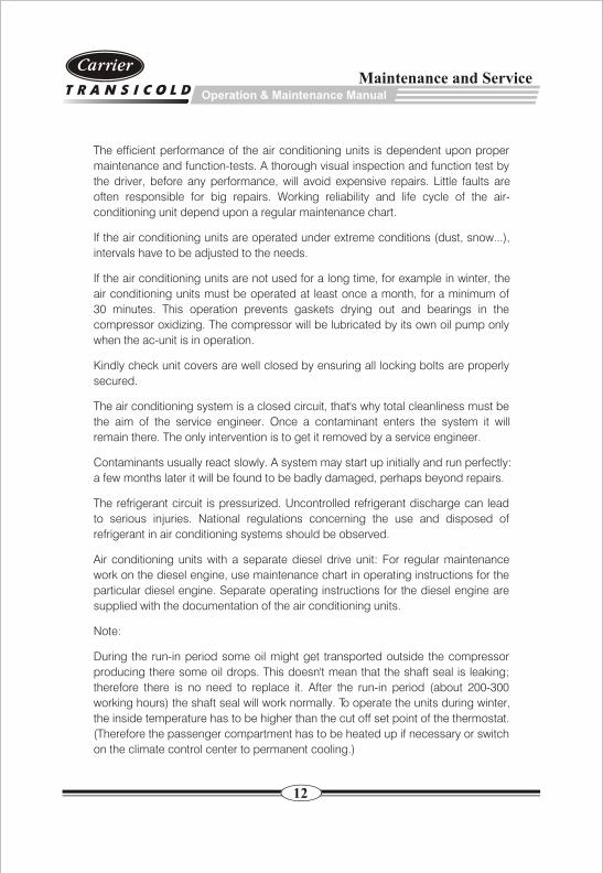
The efficient performance of the air conditioning units is dependent upon proper
maintenance and function-tests. A thorough visual inspection and function test by
the driver, before any performance, will avoid expensive repairs. Little faults are
often responsible for big repairs. Working reliability and life cycle of the air-
conditioning unit depend upon a regular maintenance chart.
If the air conditioning units are operated under extreme conditions (dust, snow...),
intervals have to be adjusted to the needs.
If the air conditioning units are not used for a long time, for example in winter, the
air conditioning units must be operated at least once a month, for a minimum of
30 minutes. This operation prevents gaskets drying out and bearings in the
compressor oxidizing. The compressor will be lubricated by its own oil pump only
when the ac-unit is in operation.
Kindly check unit covers are well closed by ensuring all locking bolts are properly
secured.
The air conditioning system is a closed circuit, that's why total cleanliness must be
the aim of the service engineer. Once a contaminant enters the system it will
remain there. The only intervention is to get it removed by a service engineer.
Contaminants usually react slowly. A system may start up initially and run perfectly:
a few months later it will be found to be badly damaged, perhaps beyond repairs.
The refrigerant circuit is pressurized. Uncontrolled refrigerant discharge can lead
to serious injuries. National regulations concerning the use and disposed of
refrigerant in air conditioning systems should be observed.
Air conditioning units with a separate diesel drive unit: For regular maintenance
work on the diesel engine, use maintenance chart in operating instructions for the
particular diesel engine. Separate operating instructions for the diesel engine are
supplied with the documentation of the air conditioning units.
Note:
During the run-in period some oil might get transported outside the compressor
producing there some oil drops. This doesn't mean that the shaft seal is leaking;
therefore there is no need to replace it. After the run-in period (about 200-300
working hours) the shaft seal will work normally. To operate the units during winter,
the inside temperature has to be higher than the cut off set point of the thermostat.
(Therefore the passenger compartment has to be heated up if necessary or switch
on the climate control center to permanent cooling.)
13
Operation & Maintenance Manual
Maintenance Chart
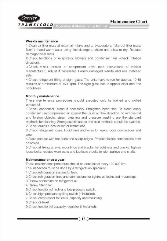
Weekly maintenance
1.Clean air filter mats at return air intake and at evaporators. Take out filter mats,
flush in hand-warm water using fine detergent, shake and allow to dry. Replace
damaged filter mats.
2.Check functions of evaporator blowers and condenser fans (check rotation
direction).
3.Check v-belt tension at compressor drive (see instructions of vehicle
manufacturer). Adjust if necessary. Renew damaged v-belts and use matched
sets.
4.Check refrigerant filling at sight glass. The units have to run for approx. 10-15
minutes at a minimum of 1500 rpm. The sight glass has to appear clear and free
of bubbles.
Monthly maintenance
These maintenance procedures should executed only by trained and skilled
personnel.
1.Check condenser, clean if necessary. Straighten bend fins. To clean dusty
condenser use compressed air against the usual air flow direction. To remove dirt
and foreign objects, steam cleaning and pressure washing are the standard
methods for cleaning. Strong caustic soaps and acid methods should be avoided.
2.Check drains tubes for dirt or restrictions.
3.Check refrigerant hoses, liquid lines and wires for leaks, loose connections and
wear.
4.Avoid contact with hot parts and sharp edges. Protect electric connections from
corrosion.
5.Check all fixing screws, mountings and bracket for tightness and cracks. Tighten
loose bolts, replace worn parts and lubricate v-belts tension pulleys and shafts.
Maintenance once a year
These maintenance procedure should be done latest every 100 000 km.
This inspection must be done by a refrigeration specialist!
1.Check refrigeration system for leak.
2.Check refrigeration lines and connections for tightness, leaks and mountings.
3.Renew contaminated refrigerant oil.
4.Renew filter drier.
5.Check function of high-and low-pressure switch.
6.Check high pressure cycling switch (if installed).
7.Check compressor for leaks, capacity and mounting.
8.Check oil level.
9.Check function of capacity regulator (if installed).
14
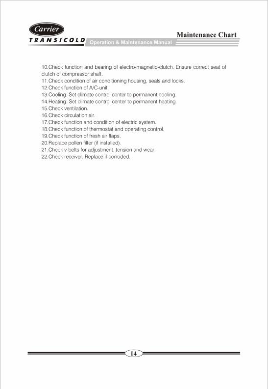
10.Check function and bearing of electro-magnetic-clutch. Ensure correct seat of
clutch of compressor shaft.
11.Check condition of air conditioning housing, seals and locks.
12.Check function of A/C-unit.
13.Cooling: Set climate control center to permanent cooling.
14.Heating: Set climate control center to permanent heating.
15.Check ventilation.
16.Check circulation air.
17.Check function and condition of electric system.
18.Check function of thermostat and operating control.
19.Check function of fresh air flaps.
20.Replace pollen filter (if installed).
21.Check v-belts for adjustment, tension and wear.
22.Check receiver. Replace if corroded.
Operation & Maintenance Manual
Maintenance Chart
15
CN268/328 & AC112
Attachment
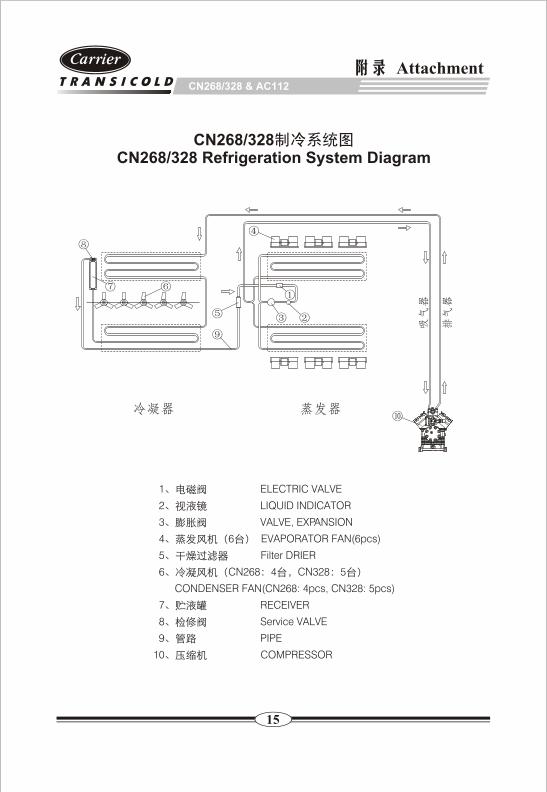
CN268/328CN268/328 Refrigeration System Diagram
1 ELECTRIC VALVE
2 LIQUID INDICATOR
3 VALVE, EXPANSION
4 6 EVAPORATOR FAN(6pcs)
5 Filter DRIER
6 CN268 4 CN328 5
CONDENSER FAN(CN268: 4pcs, CN328: 5pcs)
7 RECEIVER
8 Service VALVE
9 PIPE
10 COMPRESSOR
CN268/328 & AC112
Attachment
16
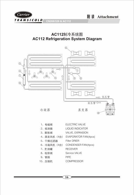
AC112AC112 Refrigeration System Diagram
1 ELECTRIC VALVE
2 LIQUID INDICATOR
3 VALVE, EXPANSION
4 4 EVAPORATOR FAN(4pcs)
5 Filter DRIER
6 4 CONDENSER FAN(4pcs)
7 RECEIVER
8 Service VALVE
9 PIPE
10 COMPRESSOR
1235 201821 86-21-59166868 86-21-59165013
Headquarter: No.1235 Ye Cheng Rd. Jiading District, Shanghai, 201821, China Tel: 86-21-59166868 Fax: 86-21-59165013
60 200434 86-21-65285295 86-21-65923827
Service Centre: No.60 Guang Yue Rd. Shanghai, 200434, China Tel: 86-21-65285295 Fax: 86-21-65923827
77-66884-00 Rev. -
Carrier Transicold China