Embed Size (px)
Citation preview
2015 - Copyright © Conforti OleodinamicaAggiornamenti su / updates on www.confortinet.com 26
1
I servocilindri ISO 6020/2 sono disponibili sia a tiranti (versione TD e TK),sia con controflange (versione TH e TX). I servocilindri sono predisposti con un trasduttore elettronico che permette di conoscere la posizione assoluta dello stelo. La scelta del tipo di trasduttore è in funzione delle prestazioni che si vogliono ottenere. La precisione di posizionamento è determinata da 2 elementi: la risoluzione del trasduttore e il sistema di comando del cilindro. I trasduttori sono previsti di 3 tipologie:• TEMPOSONIC Consente alte risoluzioni e vari tipi di controllo; può coprire tutte
le lunghezze di corsa necessarie.• POTENZIOMETRICO Il segnale di uscita è dato da un cursore che scorre su una
pista potenziometrica. La tensione è proporzionale alla posizione del cursore. La corsa massima possibile è di 500 mm.• INDUTTIVO Fornisce un segnale in tensione o in corrente, generato da un circuito
elettronico separato. La corsa massima possibile è di 1000 mm.
Versione con trasduttore esterno. Per ancoraggi X, A, E, G, H, L, RVersion with external transducer. For mountings X, A, E, G, H, L, R
Versione con trasduttore interno. Per ancoraggi B, D, C, M, Q, S, T. Consultare il nostro ufficio tecnico.Version with internal transducer. For mountings B, D, C, M, Q, S, T. Contact our technical department.
F.S. = fondo scala / full scale
I servocilindri possono essere equipaggiati con piastre di interfaccia ISO che consentono il montaggio diretto a bordo del cilindro di: - Elettrovalvole ON/OFF - Elettrovalvole proporzionali - Servovalvole
Questa configurazione abbinata a una UNITÀ DI CONTROLLO assicura una rigidità idraulica ottimale che migliora notevolmente i tempi di risposta, la ripetibilità e la precisione di posizionamento.
The servocylinders can be equipped with ISO interface plates, which allow to mount directly on the cylinder the following elements: - Solenoid valves ON/OFF - Proportional solenoid valves - Servovalves
This configuration, together with a CONTROL UNIT, ensures an optimal hydraulic rigidity, which drastically increments the answer time, the repeteability and the precision of the positioning.
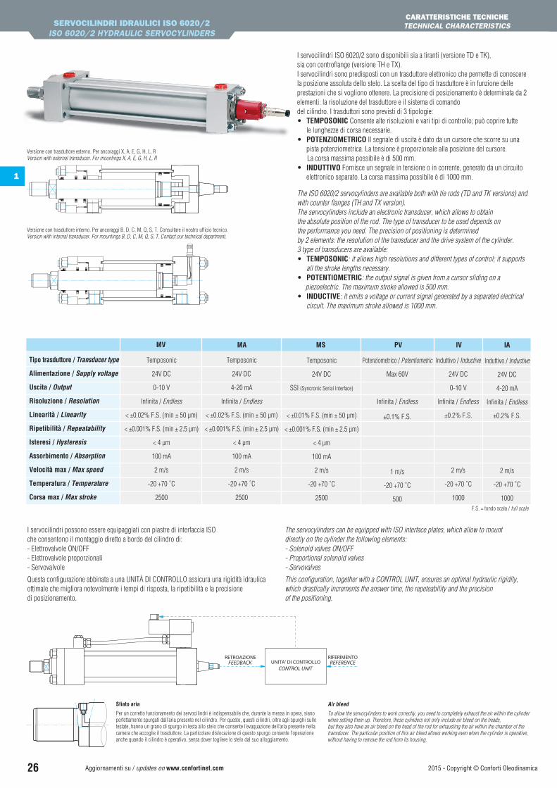
Sfiato aria
Per un corretto funzionamento dei servocilindri è indispensabile che, durante la messa in opera, siano perfettamente spurgati dall’aria presente nel cilindro. Per questo, questi cilindri, oltre agli spurghi sulle testate, hanno un grano di spurgo in testa allo stelo che consente l’evaquazione dell’aria presente nella camera che accoglie il trasduttore. La particolare dislocazione di questo spurgo consente l’operazione anche quando il cilindro è operativo, senza dover togliere lo stelo dal suo alloggiamento.
Air bleed
To allow the servocylinders to work correctly, you need to completely exhaust the air within the cylinder when setting them up. Therefore, these cylinders not only include air bleed on the heads, but they also have an air bleed on the head of the rod for exhausting the air within the chamber of the transducer. The particular position of this air bleed allows working even when the cylinder is operative, without having to remove the rod from its housing.
The ISO 6020/2 servocylinders are available both with tie rods (TD and TK versions) and with counter flanges (TH and TX version).The servocylinders include an electronic transducer, which allows to obtain the absolute position of the rod. The type of transducer to be used depends on the performance you need. The precision of positioning is determined by 2 elements: the resolution of the transducer and the drive system of the cylinder. 3 type of transducers are available:• TEMPOSONIC: it allows high resolutions and different types of control; it supports
all the stroke lengths necessary.• POTENTIOMETRIC: the output signal is given from a cursor sliding on a piezoelectric. The maximum stroke allowed is 500 mm.• INDUCTIVE: it emits a voltage or current signal generated by a separated electrical
circuit. The maximum stroke allowed is 1000 mm.
Temposonic
24V DC
0-10 V
Infinita / Endless
< ±0.02% F.S. (min ± 50 µm)
< ±0.001% F.S. (min ± 2.5 µm)
< 4 µm
100 mA
2 m/s
-20 +70 ˚C
2500
MV
Temposonic
24V DC
4-20 mA
Infinita / Endless
< ±0.02% F.S. (min ± 50 µm)
< ±0.001% F.S. (min ± 2.5 µm)
< 4 µm
100 mA
2 m/s
-20 +70 ˚C
2500
MA
Temposonic
24V DC
SSI (Syncronic Serial Interface)
< ±0.01% F.S. (min ± 50 µm)
< ±0.001% F.S. (min ± 2.5 µm)
< 4 µm
100 mA
2 m/s
-20 +70 ˚C
2500
MS
Potenziometrico / Potentiometric
Max 60V
Infinita / Endless
±0.1% F.S.
1 m/s
-20 +70 ˚C
500
PV
Induttivo / Inductive
24V DC
0-10 V
Infinita / Endless
±0.2% F.S.
2 m/s
-20 +70 ˚C
1000
IV
Induttivo / Inductive
24V DC
4-20 mA
Infinita / Endless
±0.2% F.S.
2 m/s
-20 +70 ˚C
1000
IA
Tipo trasduttore / Transducer type
Alimentazione / Supply voltage
Uscita / Output
Risoluzione / Resolution
Linearità / Linearity
Ripetibilità / Repeatability
Isteresi / Hysteresis
Assorbimento / Absorption
Velocità max / Max speed
Temperatura / Temperature
Corsa max / Max stroke
SERVOCILINDRI IDRAULICI ISO 6020/2ISO 6020/2 HYDRAULIC SERVOCYLINDERS
CARATTERISTICHE TECNICHETECHNICAL CHARACTERISTICS
2015 - Copyright © Conforti Oleodinamica Aggiornamenti su / updates on www.confortinet.com 27
1
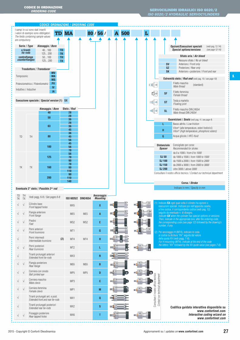
CODICE ORDINAZIONE / ORDERING CODE
56TD MA 80 A/ /I campi in cui sono stati inseriti i valori di esempio sono obbligatori.The fields containing sample values are compulsory.
Stelo / Rod
TH
TX
TD
TK
40
50
63
80
100
125
160
200
2828362836453645564556705670907090
11090
110140
Alesaggio / Bore
Esecuzione speciale / Special version (1) SX
500
Guarnizioni / Seals (vedi pag. 4 / see page 4)
L
H
G
Basso attrito / Low frictionViton® (alte temperature, esteri fosforici)Viton® (high temperature, phosphoric esters)
Acqua glicole / HFC-fluid
DistanzialeSpacer
SJ 50SJ 100SJ 150SJ 200
da 0 a 1000 / from 0 to 1000da 1000 a 1500 / from 1000 to 1500da 1500 a 2000 / from 1500 to 2000da 2000 a 3000 / from 2000 to 3000oltre 3000 / above 3000
Consigliato per corse:Recommended for stroke:
Corsa / Stroke
Indicare in mm / Specify in mm
Consultare il nostro ufficio tecnico / Contact our technical department
Opzioni/Esecuzioni speciali Special options/versions
(vedi pag. 12-14) (see page 12-14)
Estremità stelo / Rod end (vedi pag. 10 / see page 10)
SF
ST
SL
Filetto maschio Male thread
Filetto femmina Female thread
Testa a martello Floating joint
Filetto maschio DIN 24554 Male thread DIN 24554
(standard)
Codifica guidata interattiva disponibile suwww.confortinet.com
Interactive coding wizard onwww.confortinet.com
SERVOCILINDRI IDRAULICI ISO 6020/2ISO 6020/2 HYDRAULIC SERVOCYLINDERS
CODICE DI ORDINAZIONEORDERING CODE
Trasduttore / Transducer MVTemposonic MA MSPotenziometrico / Potentiometric PV
Induttivo / Inductive IV IA
MVMAMSPVIVIA
L
AncoraggioMounting
MX5
ME5
MS2
MT1
MT4
MT2
MX3
ME6
MP5
MP3
MP1
MX1
MX2
MX6
Cilindro base Front tapped holes
Flangia anteriore Front flange
Piedini Feet
Perni anteriori Front trunnions
Perni intermedi Intermediate trunnions
Perni posteriori Rear trunnions
Tiranti prolungati anteriori Extended front tie-rods
Flangia posteriore Rear flange
Cerniera con snodo Ball jointed eye
Cerniera maschio Male clevis
Cerniera femmina Female clevis
Tiranti prolungati ant. e post. Extended front and rear tie-rods
Tiranti prolungati posteriori Extended rear tie-rods
Fissaggio posteriore Rear tapped holes
X
A
E
G
H
L
R
B
D
C
M
Q
S
T
ISO 6020/2 DIN24554
ME5
MS2
MT4
ME6
MP5
(2)
Vedi pagg. 6-8 / See pages 6-8TD TH
√ √
√ √
√ √
√ √
√
√ √
√ √
√ √
√ √
√ √
√ √
√
√
√
TK TX
Cons
ulta
re il
nos
tro u
ffici
o te
cnic
oCo
ntac
t our
tech
nica
l dep
artm
ent
40... 100 TDTKTHTX
50... 100125... 200
125... 200
Alesaggio / BoreSerie / Typea tirantitie rods
controflangecounterflanges
Eventuale 2° stelo / Possible 2nd rod
Sfiato aria / Air bleed
SVSZSK
Nessuno sfiato / No air bleedAnteriore / Front onlyPosteriore / Rear onlyAnteriore + posteriore / Front and rear
(1) Indicare SX ogni qual volta il cilindro ha opzioni o esecuzioni speciali. Indicare poi nell’apposita casella, a fine codice, il corrispondente codice (vedi pag. 12) seguito da eventuale n. di disegno. Indicate SX when the cylinder has special options or versions. Then, indicate in the appropriate box, after the ordering code, the corresponding code (see page 12) followed by the drawing’s number, if any.
(2) Per ancoraggio H (MT4), indicare in coda al codice la dicitura “XV” seguita dal valore della quota XV (vedi pagg. 7-8). For H mounting (MT4), indicate at the end of the code the letters “XV” followed by the XV quote value (see pages 7-8).


![[] CILINDRI IDRAULICI ISO 6020/2 - Autin s.r.l. · [] CILINDRI IDRAULICI ISO 6020/2 - Autin s.r.l. ... 1](https://img.pdfslide.tips/doc/110x75/5be4ac0809d3f2ad378dc3f0/-cilindri-idraulici-iso-60202-autin-srl-cilindri-idraulici-iso-60202.jpg)