Embed Size (px)
Citation preview

INSTRUCTION MANUAL
Read and understand all of the instructions and safety information in this manual before operating or servicing this tool.
Register this product at www.greenlee.com52067011 © 2013 Greenlee Textron Inc. 8/13
SG4 Shotgun Shoe Group for 555® Series Electric Benders
SG4 Shotgun Shoe Group for 555® Series Electric Benders
Greenlee / A Textron Company 4455 Boeing Dr. • Rockford, IL 61109-2988 USA • 815-397-70702
All specifications are nominal and may change as design improvements occur. Greenlee Textron Inc. shall not be liable for damages resulting from misapplication or misuse of its products.
555 is a registered trademark of Textron Innovations Inc.
KEEP THIS MANUAL
Table of Contents
Description .................................................................... 2
Safety ............................................................................ 2
Purpose of this Manual ................................................. 2
Other Publications ......................................................... 2
Important Safety Information .....................................3–4
Bending Attachment Group .......................................... 5
Setup ............................................................................. 6
Operation ....................................................................7–8
Illustrated Bending Glossary ......................................... 9
Bending Instructions ................................................... 10
Additional Bending Instructions .................................. 10
Additional Bending Tables ........................................... 11
Illustration and Parts List ............................................. 12
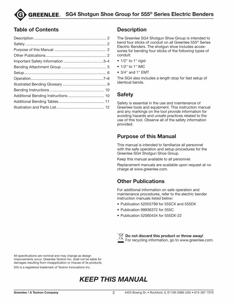
Description
The Greenlee SG4 Shotgun Shoe Group is intended to bend four sticks of conduit on all Greenlee 555® Series Electric Benders. The shotgun shoe includes acces-sories for bending four sticks of the following types of conduit:
• 1/2" to 1" rigid
• 1/2" to 1" IMC
• 3/4" and 1" EMT
The SG4 also includes a length stop for fast setup of identical bends.
Safety
Safety is essential in the use and maintenance of Greenlee tools and equipment. This instruction manual and any markings on the tool provide information for avoiding hazards and unsafe practices related to the use of this tool. Observe all of the safety information provided.
Purpose of this Manual
This manual is intended to familiarize all personnel with the safe operation and setup procedures for the Greenlee SG4 Shotgun Shoe Group.
Keep this manual available to all personnel.
Replacement manuals are available upon request at no charge at www.greenlee.com.
Other Publications
For additional information on safe operation and maintenance procedures, refer to the electric bender instruction manuals listed below:
• Publication 52055799 for 555CX and 555DX
• Publication 99936372 for 555C
• Publication 52060434 for 555DX-22
Do not discard this product or throw away! For recycling information, go to www.greenlee.com.
SG4 Shotgun Shoe Group for 555® Series Electric Benders
Greenlee / A Textron Company 4455 Boeing Dr. • Rockford, IL 61109-2988 USA • 815-397-70703
IMPORTANT SAFETY INFORMATION
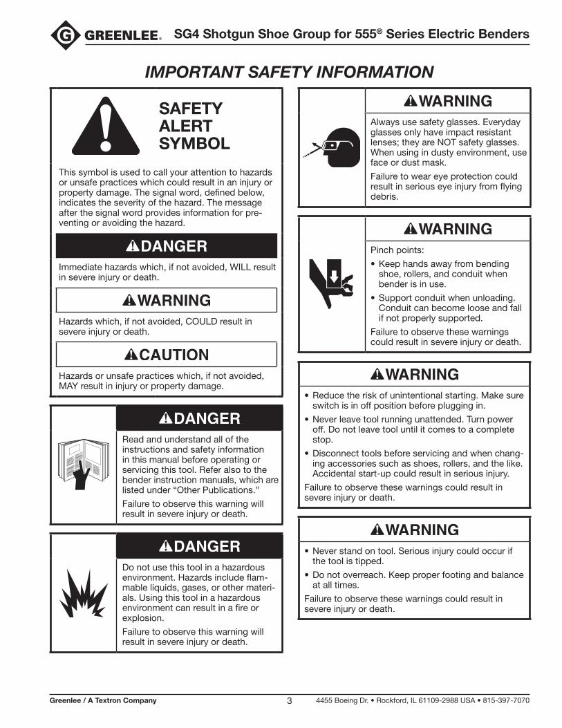
SAFETY ALERT SYMBOL
This symbol is used to call your attention to hazards or unsafe practices which could result in an injury or property damage. The signal word, defined below, indicates the severity of the hazard. The message after the signal word provides information for pre-venting or avoiding the hazard.
Immediate hazards which, if not avoided, WILL result in severe injury or death.
Hazards which, if not avoided, COULD result in severe injury or death.
Hazards or unsafe practices which, if not avoided, MAY result in injury or property damage.
Read and understand all of the instructions and safety information in this manual before operating or servicing this tool. Refer also to the bender instruction manuals, which are listed under “Other Publications.”
Failure to observe this warning will result in severe injury or death.
Do not use this tool in a hazardous environment. Hazards include flam-mable liquids, gases, or other materi-als. Using this tool in a hazardous environment can result in a fire or explosion.
Failure to observe this warning will result in severe injury or death.
Always use safety glasses. Everyday glasses only have impact resistant lenses; they are NOT safety glasses. When using in dusty environment, use face or dust mask.
Failure to wear eye protection could result in serious eye injury from flying debris.
Pinch points:
• Keep hands away from bending shoe, rollers, and conduit when bender is in use.
• Support conduit when unloading. Conduit can become loose and fall if not properly supported.
Failure to observe these warnings could result in severe injury or death.
• Reduce the risk of unintentional starting. Make sure switch is in off position before plugging in.
• Never leave tool running unattended. Turn power off. Do not leave tool until it comes to a complete stop.
• Disconnect tools before servicing and when chang-ing accessories such as shoes, rollers, and the like. Accidental start-up could result in serious injury.
Failure to observe these warnings could result in severe injury or death.
• Never stand on tool. Serious injury could occur if the tool is tipped.
• Do not overreach. Keep proper footing and balance at all times.
Failure to observe these warnings could result in severe injury or death.
SG4 Shotgun Shoe Group for 555® Series Electric Benders
Greenlee / A Textron Company 4455 Boeing Dr. • Rockford, IL 61109-2988 USA • 815-397-70704
IMPORTANT SAFETY INFORMATION
• Conduit moves rapidly as it is bent. The path of the conduit must be clear of obstructions. Be sure clearance is adequate before starting the bend.
• Wear proper apparel. Do not wear loose clothing, gloves, neckties, rings, bracelets, or other jewelry which may get caught in moving parts. Nonslip footwear is recommended. Wear protective hair covering to contain long hair.
• Do not force rollers or alter tool. It will do the job better and safer at the rate for which it was designed.
• Use right tool. Do not force tool or attachment to do a job for which it was not designed.
• Use this tool for the manufacturer’s intended purpose only. Use other than that which is instructed in this manual can result in injury or property damage.
Failure to observe these precautions may result in injury or property damage.
• Keep work area clean. Cluttered areas and benches invite accidents.
• Keep children away. All visitors should be kept safe distance from work area.
• Make workshop kid proof with padlocks, master switches, or by removing starter keys.
Failure to observe these precautions may result in injury or property damage.
• Inspect the bender before use. Replace worn, damaged, or missing parts with Greenlee replace-ment parts. A damaged or improperly assem-bled component could break and strike nearby personnel.
• Maintain tools with care. Keep tool clean for best and safest performance. Follow instructions for lubricating and changing accessories.
• Check damaged parts. Before further use of the tool, a guard or other part that is damaged should be carefully checked to determine that it will operate properly and perform its intended func-tion. Check for alignment of moving parts, binding of moving parts, breakage of parts, mounting, and any other conditions that may affect its operation. A guard or other part that is damaged should be properly repaired or replaced.
• Use recommended accessories. Consult the instruction manual for recommended accessories. The use of improper accessories may cause risk of injury to persons.
• Some bender parts and accessories are heavy and may require more than one person to lift and assemble.
Failure to observe these precautions may result in injury or property damage.
Note: Keep all decals clean and legible, and replace when necessary.
SG4 Shotgun Shoe Group for 555® Series Electric Benders
Greenlee / A Textron Company 4455 Boeing Dr. • Rockford, IL 61109-2988 USA • 815-397-70705
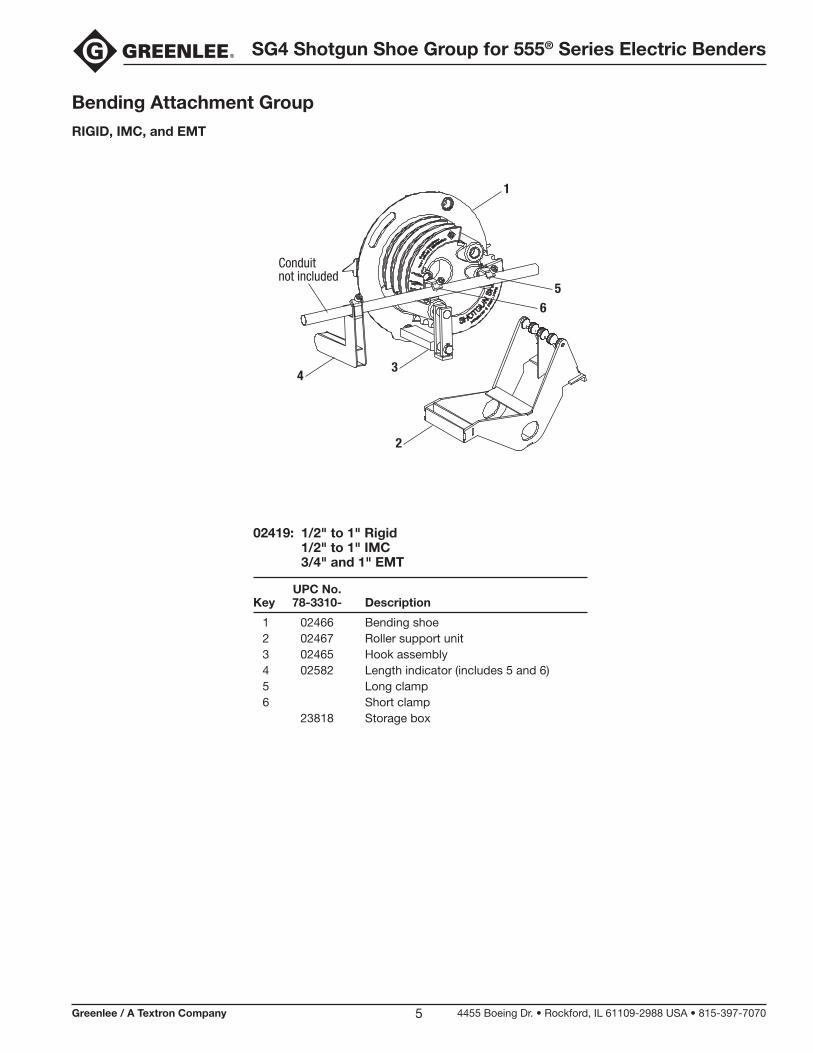
Bending Attachment GroupRIGID, IMC, and EMT
02419: 1/2" to 1" Rigid 1/2" to 1" IMC 3/4" and 1" EMT
UPC No. Key 78-3310- Description
1 02466 Bending shoe 2 02467 Roller support unit 3 02465 Hook assembly 4 02582 Length indicator (includes 5 and 6) 5 Long clamp 6 Short clamp 23818 Storage box
1
34
2
56
Conduitnot included
SG4 Shotgun Shoe Group for 555® Series Electric Benders
Greenlee / A Textron Company 4455 Boeing Dr. • Rockford, IL 61109-2988 USA • 815-397-70706
Setup
Always use safety glasses. Everyday glasses only have impact resistant lenses; they are NOT safety glasses. When using in dusty environment, use face or dust mask.
Failure to wear eye protection could result in serious eye injury from flying debris.
Unplug the bender before changing accessories. Accidental start-up could result in serious injury.
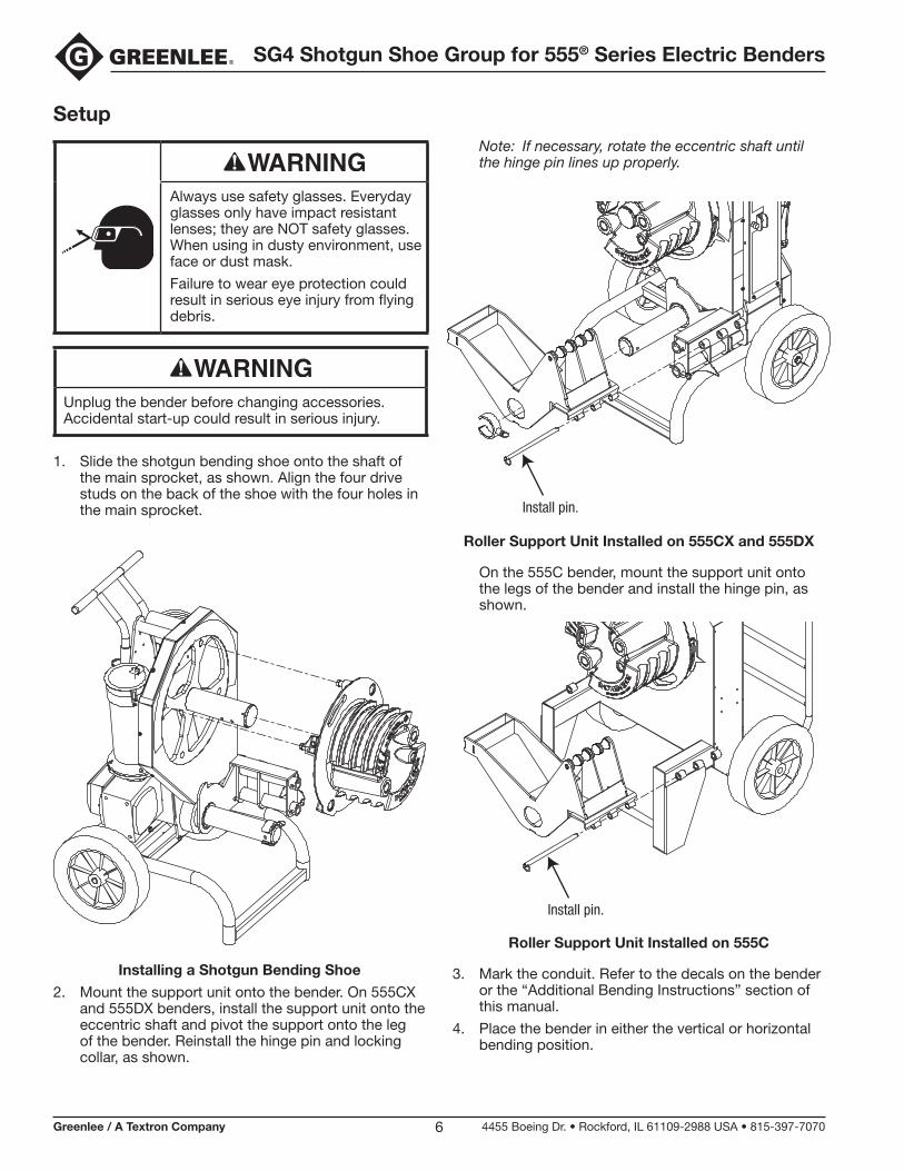
1. Slide the shotgun bending shoe onto the shaft of the main sprocket, as shown. Align the four drive studs on the back of the shoe with the four holes in the main sprocket.
Installing a Shotgun Bending Shoe
2. Mount the support unit onto the bender. On 555CX and 555DX benders, install the support unit onto the eccentric shaft and pivot the support onto the leg of the bender. Reinstall the hinge pin and locking collar, as shown.
Note: If necessary, rotate the eccentric shaft until the hinge pin lines up properly.
Install pin.
Roller Support Unit Installed on 555CX and 555DX
On the 555C bender, mount the support unit onto the legs of the bender and install the hinge pin, as shown.
Install pin.
Roller Support Unit Installed on 555C
3. Mark the conduit. Refer to the decals on the bender or the “Additional Bending Instructions” section of this manual.
4. Place the bender in either the vertical or horizontal bending position.
SG4 Shotgun Shoe Group for 555® Series Electric Benders
Greenlee / A Textron Company 4455 Boeing Dr. • Rockford, IL 61109-2988 USA • 815-397-70707
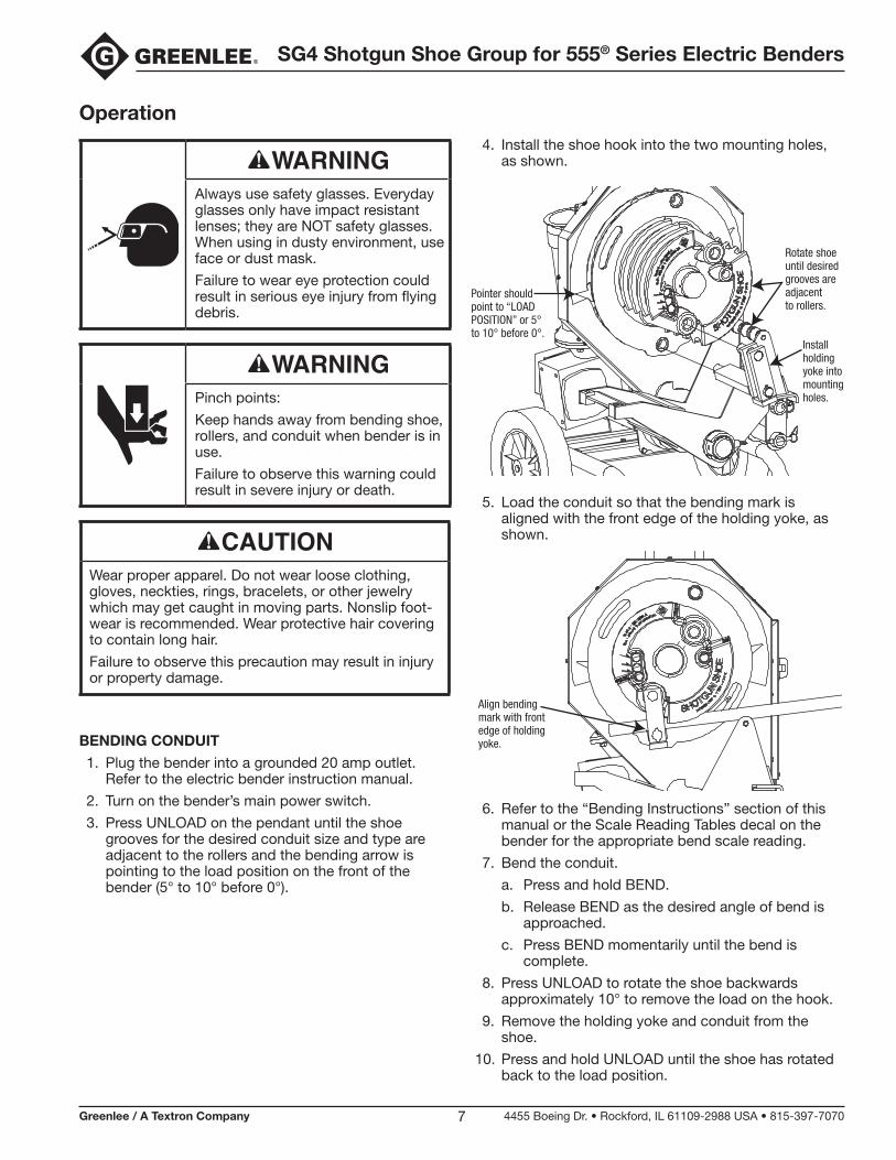
Operation
Always use safety glasses. Everyday glasses only have impact resistant lenses; they are NOT safety glasses. When using in dusty environment, use face or dust mask.
Failure to wear eye protection could result in serious eye injury from flying debris.
Pinch points:
Keep hands away from bending shoe, rollers, and conduit when bender is in use.
Failure to observe this warning could result in severe injury or death.
Wear proper apparel. Do not wear loose clothing, gloves, neckties, rings, bracelets, or other jewelry which may get caught in moving parts. Nonslip foot-wear is recommended. Wear protective hair covering to contain long hair.
Failure to observe this precaution may result in injury or property damage.
BENDING CONDUIT
1. Plug the bender into a grounded 20 amp outlet. Refer to the electric bender instruction manual.
2. Turn on the bender’s main power switch.
3. Press UNLOAD on the pendant until the shoe grooves for the desired conduit size and type are adjacent to the rollers and the bending arrow is pointing to the load position on the front of the bender (5° to 10° before 0°).
4. Install the shoe hook into the two mounting holes, as shown.
Rotate shoeuntil desiredgrooves areadjacentto rollers.
Installholdingyoke intomountingholes.
Pointer should point to “LOAD POSITION” or 5° to 10° before 0°.
5. Load the conduit so that the bending mark is aligned with the front edge of the holding yoke, as shown.
Align bendingmark with frontedge of holdingyoke.
6. Refer to the “Bending Instructions” section of this manual or the Scale Reading Tables decal on the bender for the appropriate bend scale reading.
7. Bend the conduit.
a. Press and hold BEND.
b. Release BEND as the desired angle of bend is approached.
c. Press BEND momentarily until the bend is complete.
8. Press UNLOAD to rotate the shoe backwards approximately 10° to remove the load on the hook.
9. Remove the holding yoke and conduit from the shoe.
10. Press and hold UNLOAD until the shoe has rotated back to the load position.
SG4 Shotgun Shoe Group for 555® Series Electric Benders
Greenlee / A Textron Company 4455 Boeing Dr. • Rockford, IL 61109-2988 USA • 815-397-70708
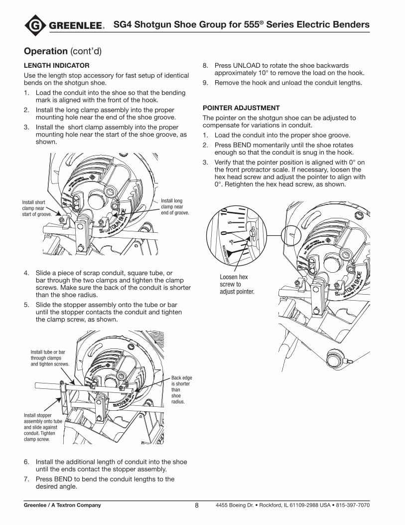
Operation (cont’d)LENGTH INDICATOR
Use the length stop accessory for fast setup of identical bends on the shotgun shoe.
1. Load the conduit into the shoe so that the bending mark is aligned with the front of the hook.
2. Install the long clamp assembly into the proper mounting hole near the end of the shoe groove.
3. Install the short clamp assembly into the proper mounting hole near the start of the shoe groove, as shown.
Install short clamp near start of groove.
Install long clamp near end of groove.
4. Slide a piece of scrap conduit, square tube, or bar through the two clamps and tighten the clamp screws. Make sure the back of the conduit is shorter than the shoe radius.
5. Slide the stopper assembly onto the tube or bar until the stopper contacts the conduit and tighten the clamp screw, as shown.
Install tube or bar through clamps and tighten screws.
Install stopper assembly onto tube and slide against conduit. Tighten clamp screw.
Back edgeis shorterthanshoe radius.
6. Install the additional length of conduit into the shoe until the ends contact the stopper assembly.
7. Press BEND to bend the conduit lengths to the desired angle.
8. Press UNLOAD to rotate the shoe backwards approximately 10° to remove the load on the hook.
9. Remove the hook and unload the conduit lengths.
POINTER ADJUSTMENT
The pointer on the shotgun shoe can be adjusted to compensate for variations in conduit.
1. Load the conduit into the proper shoe groove.
2. Press BEND momentarily until the shoe rotates enough so that the conduit is snug in the hook.
3. Verify that the pointer position is aligned with 0° on the front protractor scale. If necessary, loosen the hex head screw and adjust the pointer to align with 0°. Retighten the hex head screw, as shown.
Loosen hex screw to adjust pointer.
SG4 Shotgun Shoe Group for 555® Series Electric Benders
Greenlee / A Textron Company 4455 Boeing Dr. • Rockford, IL 61109-2988 USA • 815-397-70709
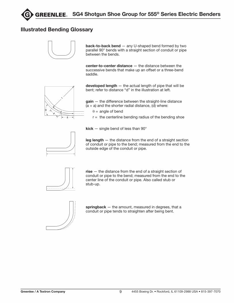
Illustrated Bending Glossary
back-to-back bend — any U-shaped bend formed by two parallel 90° bends with a straight section of conduit or pipe between the bends.
center-to-center distance — the distance between the successive bends that make up an offset or a three-bend saddle.
developed length — the actual length of pipe that will be bent; refer to distance “d” in the illustration at left.
gain — the difference between the straight-line distance (a + a) and the shorter radial distance, (d) where:
q = angle of bend
r = the centerline bending radius of the bending shoe
kick — single bend of less than 90°
leg length — the distance from the end of a straight section of conduit or pipe to the bend; measured from the end to the outside edge of the conduit or pipe.
rise — the distance from the end of a straight section of conduit or pipe to the bend; measured from the end to the center line of the conduit or pipe. Also called stub or stub-up.
springback — the amount, measured in degrees, that a conduit or pipe tends to straighten after being bent.
a
a
d
r
SG4 Shotgun Shoe Group for 555® Series Electric Benders
Greenlee / A Textron Company 4455 Boeing Dr. • Rockford, IL 61109-2988 USA • 815-397-707010
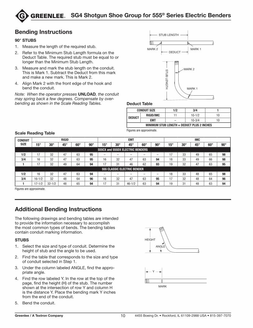
Bending Instructions90° STUBS
1. Measure the length of the required stub.
2. Refer to the Minimum Stub Length formula on the Deduct Table. The required stub must be equal to or longer than the Minimum Stub Length.
3. Measure and mark the stub length on the conduit. This is Mark 1. Subtract the Deduct from this mark and make a new mark. This is Mark 2.
4. Align Mark 2 with the front edge of the hook and bend the conduit.
Note: When the operator presses UNLOAD, the conduit may spring back a few degrees. Compensate by over-bending as shown in the Scale Reading Tables.
Scale Reading Table
CONDUIT SIZE
RIGID EMT IMC
15° 30° 45° 60° 90° 15° 30° 45° 60° 90° 15° 30° 45° 60° 90°555CX and 555DX ELECTRIC BENDERS
1/2 17 32 47 63 95 – – – – – 17 33 49 65 983/4 16 32 47 63 95 16 32 47 63 94 18 33 49 66 981 17 32 49 64 94 17 31 46 62 93 19 32 47 63 95
555 CLASSIC ELECTRIC BENDER1/2 16 32 47 63 94 – – – – – 18 33 48 65 983/4 16-1/2 32 48 64 96 16 32 47 63 95 17 32 48 64 961 17-1/2 32-1/2 48 65 94 17 31 46-1/2 63 94 19 31 48 63 94
Figures are approximate.
STUB LENGTH
DEDUCT MARK 2
MARK 2
MARK 1
MARK 1S
TUB
LEN
GTH
Deduct Table
CONDUIT SIZE 1/2 3/4 1
DEDUCTRIGID/IMC 11 10-1/2 10
EMT – 10-3/4 10
MINIMUM STUB LENGTH = DEDUCT PLUS 2 INCHES
Figures are approximate.
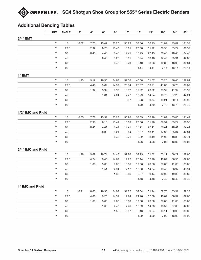
Additional Bending Instructions
The following drawings and bending tables are intended to provide the information necessary to accomplish the most common types of bends. The bending tables contain conduit marking information.
STUBS
1. Select the size and type of conduit. Determine the height of stub and the angle to be used.
2. Find the table that corresponds to the size and type of conduit selected in Step 1.
3. Under the column labeled ANGLE, find the appro-priate angle.
4. Find the row labeled Y. In the row at the top of the page, find the height (H) of the stub. The number shown at the intersection of row Y and column H is the distance Y. Place the bending mark Y inches from the end of the conduit.
5. Bend the conduit.
Y
HEIGHT
MARK
ANGLE
SG4 Shotgun Shoe Group for 555® Series Electric Benders
Greenlee / A Textron Company 4455 Boeing Dr. • Rockford, IL 61109-2988 USA • 815-397-707011
Additional Bending Tables DIM ANGLE 2" 4" 6" 8" 10" 12" 15" 18" 24" 36"
3/4" EMT Y 15 0.02 7.75 15.47 23.20 30.93 38.66 50.25 61.84 85.02 131.38
Y 22.5 2.97 8.20 13.43 18.65 23.88 31.72 39.56 55.24 86.59
Y 30 0.45 4.45 8.45 12.45 16.45 22.45 28.45 40.45 64.45
Y 45 0.45 3.28 6.11 8.94 13.18 17.42 25.91 42.88
Y 60 0.48 2.79 5.10 8.56 12.03 18.96 32.81
Y 90 1.14 4.14 7.14 13.14 25.14
1" EMT Y 15 1.45 9.17 16.90 24.63 32.36 40.08 51.67 63.26 86.45 132.81
Y 22.5 4.46 9.69 14.92 20.14 25.37 33.21 41.05 56.73 88.09
Y 30 1.92 5.92 9.92 13.92 17.92 23.92 29.92 41.92 65.92
Y 45 1.81 4.64 7.47 10.29 14.54 18.78 27.26 44.24
Y 60 3.97 6.28 9.74 13.21 20.14 33.99
Y 90 1.79 4.79 7.79 13.79 25.79
1/2" IMC and Rigid Y 15 0.05 7.78 15.51 23.23 30.96 38.69 50.28 61.87 85.05 131.42
Y 22.5 2.96 8.18 13.41 18.63 23.86 31.70 39.54 55.22 86.58
Y 30 0.41 4.41 8.41 12.41 16.41 22.41 28.41 40.41 64.41
Y 45 0.38 3.21 6.04 8.87 13.11 17.35 25.84 42.81
Y 60 0.40 2.71 5.02 8.49 11.95 18.88 32.74
Y 90 1.06 4.06 7.06 13.06 25.06
3/4" IMC and Rigid Y 15 1.29 9.02 16.74 24.47 32.20 39.93 51.52 63.11 86.29 132.65
Y 22.5 4.24 9.46 14.69 19.92 25.14 32.98 40.82 56.50 87.86
Y 30 1.66 5.66 9.66 13.66 17.66 23.66 29.66 41.66 65.66
Y 45 1.51 4.34 7.17 10.00 14.24 18.48 26.97 43.94
Y 60 1.35 3.66 5.97 9.44 12.90 19.83 33.68
Y 90 1.48 4.48 7.48 13.48 25.48
1" IMC and Rigid Y 15 0.91 8.63 16.36 24.09 31.82 39.54 51.14 62.73 85.91 132.27
Y 22.5 4.06 9.28 14.51 19.74 24.96 32.80 40.64 56.32 87.68
Y 30 1.60 5.60 9.60 13.60 17.60 23.60 29.60 41.60 65.60
Y 45 1.60 4.43 7.26 10.09 14.33 18.57 27.06 44.03
Y 60 1.56 3.87 6.18 9.64 13.11 20.03 33.89
Y 90 1.92 4.92 7.92 13.92 25.92
SG4 Shotgun Shoe Group for 555® Series Electric Benders
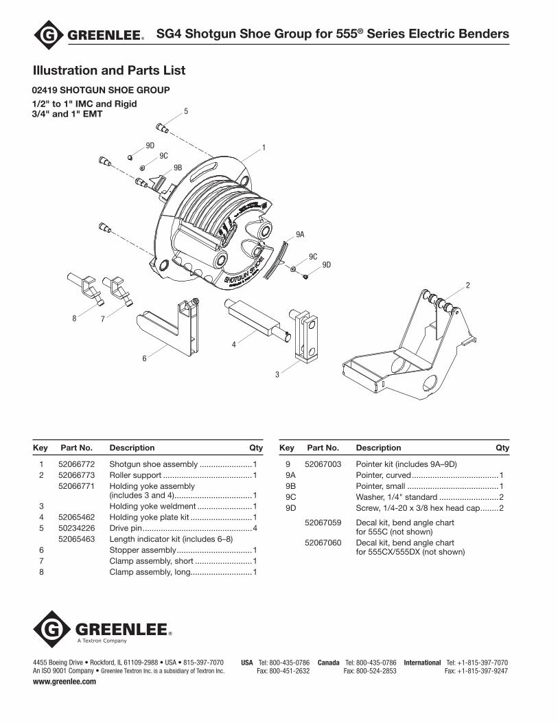
1 52066772 Shotgun shoe assembly .......................1 2 52066773 Roller support .......................................1 52066771 Holding yoke assembly (includes 3 and 4) ..................................1 3 Holding yoke weldment ........................1 4 52065462 Holding yoke plate kit ...........................1 5 50234226 Drive pin ................................................4 52065463 Length indicator kit (includes 6–8) 6 Stopper assembly .................................1 7 Clamp assembly, short .........................1 8 Clamp assembly, long...........................1
Illustration and Parts List02419 SHOTGUN SHOE GROUP
1/2" to 1" IMC and Rigid 3/4" and 1" EMT 5
1
2
4
3
6
78
9D9C
9B
9D9C
9A
Key Part No. Description Qty Key Part No. Description Qty
9 52067003 Pointer kit (includes 9A–9D) 9A Pointer, curved ......................................1 9B Pointer, small ........................................1 9C Washer, 1/4" standard ..........................2 9D Screw, 1/4-20 x 3/8 hex head cap ........2
52067059 Decal kit, bend angle chart for 555C (not shown) 52067060 Decal kit, bend angle chart for 555CX/555DX (not shown)
4455 Boeing Drive • Rockford, IL 61109-2988 • USA • 815-397-7070An ISO 9001 Company • Greenlee Textron Inc. is a subsidiary of Textron Inc.
USA Tel: 800-435-0786 Fax: 800-451-2632
Canada Tel: 800-435-0786 Fax: 800-524-2853
International Tel: +1-815-397-7070 Fax: +1-815-397-9247
www.greenlee.com