Embed Size (px)
Citation preview
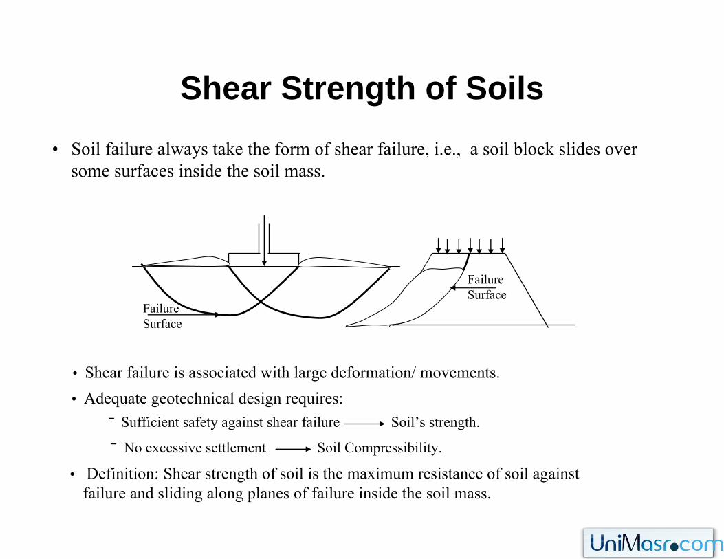
Shear Strength of Soils• Soil failure always take the form of shear failure, i.e., a soil block slides over
some surfaces inside the soil mass.
Failure Surface
Failure Surface
• Shear failure is associated with large deformation/ movements.
‾ Sufficient safety against shear failure Soil’s strength.
‾ No excessive settlement Soil Compressibility.
• Adequate geotechnical design requires:
• Definition: Shear strength of soil is the maximum resistance of soil againstfailure and sliding along planes of failure inside the soil mass.
Shear Strength of SoilsNormal and Shear Stress on a Plane
D
σy
A
C
B
τ
σx σx
σy
τσθ τθ
E
F
a
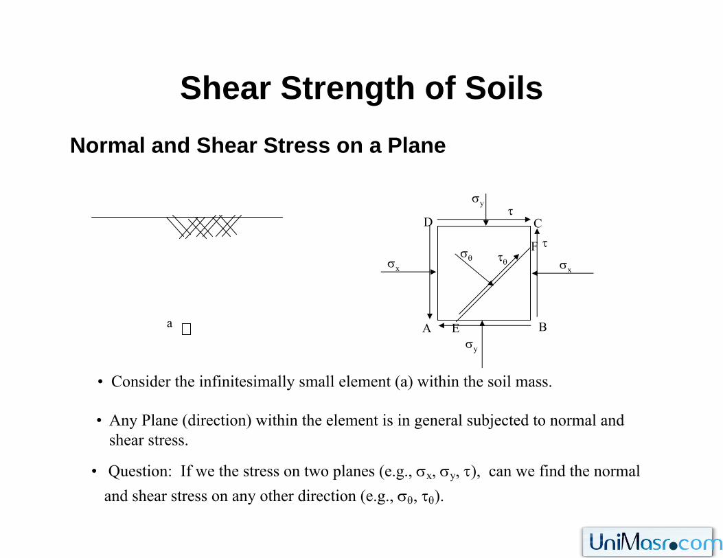
• Consider the infinitesimally small element (a) within the soil mass.
• Any Plane (direction) within the element is in general subjected to normal and shear stress.
• Question: If we the stress on two planes (e.g., σx, σy, τ), can we find the normal and shear stress on any other direction (e.g., σθ, τθ).
Shear Strength of SoilsNormal and Shear Stress on a Plane
D
σy
A
C
B
τ
σx σx
σy
τσθ τθ
E
F
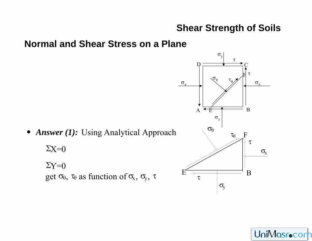
• Answer (1): Using Analytical Approach
ΣX=0
ΣY=0get σθ, τθ as function of σx, σy, τ τ
σx
σy
ττθ
σθF
BE
Shear Strength of SoilsNormal and Shear Stress on a Plane
D
σy
A
C
B
τ
σx σx
σy
τσθ τθ
E
F
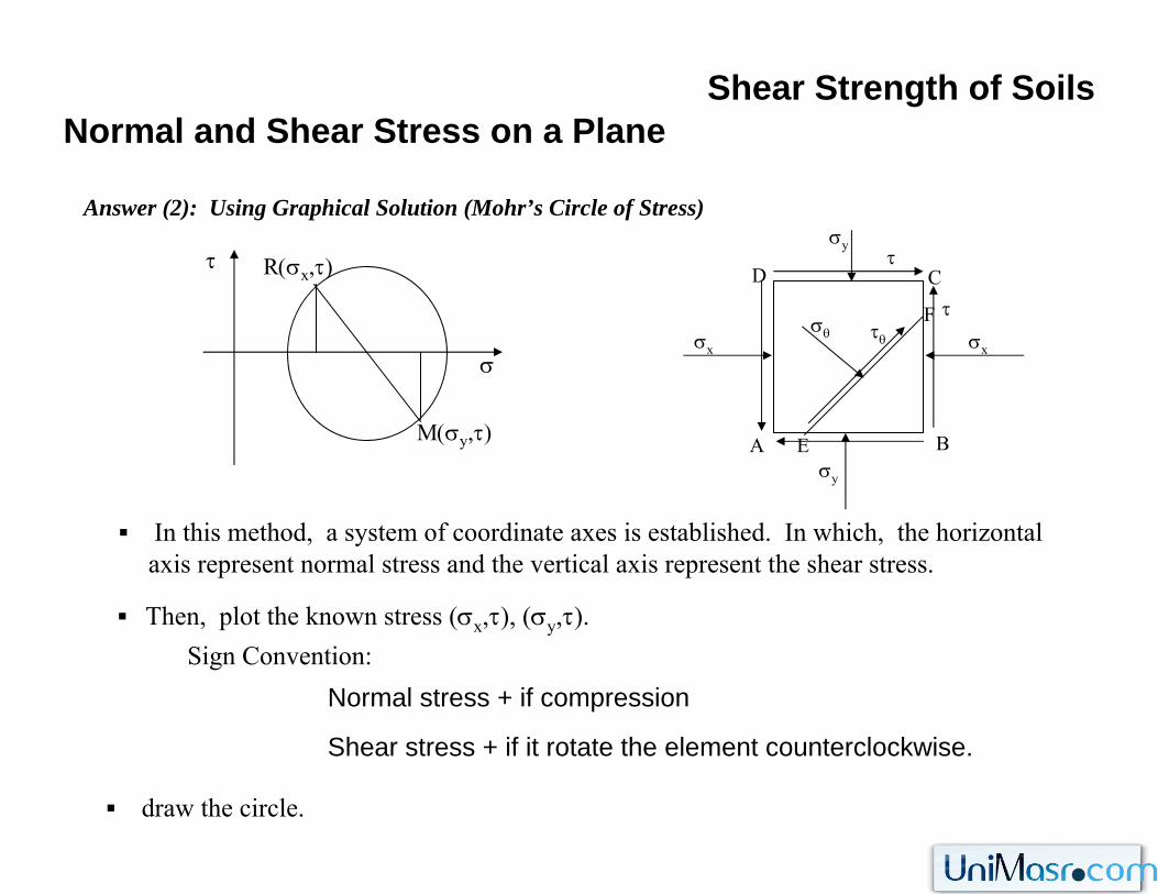
Answer (2): Using Graphical Solution (Mohr’s Circle of Stress)
σ
R(σx,τ)τ
M(σy,τ)
In this method, a system of coordinate axes is established. In which, the horizontal axis represent normal stress and the vertical axis represent the shear stress.
Then, plot the known stress (σx,τ), (σy,τ).Sign Convention:
Normal stress + if compression
Shear stress + if it rotate the element counterclockwise.
draw the circle.
Shear Strength of SoilsNormal and Shear Stress on a Plane
D
σy
A
C
B
τ
σx σx
σy
τσθ τθ
E
F
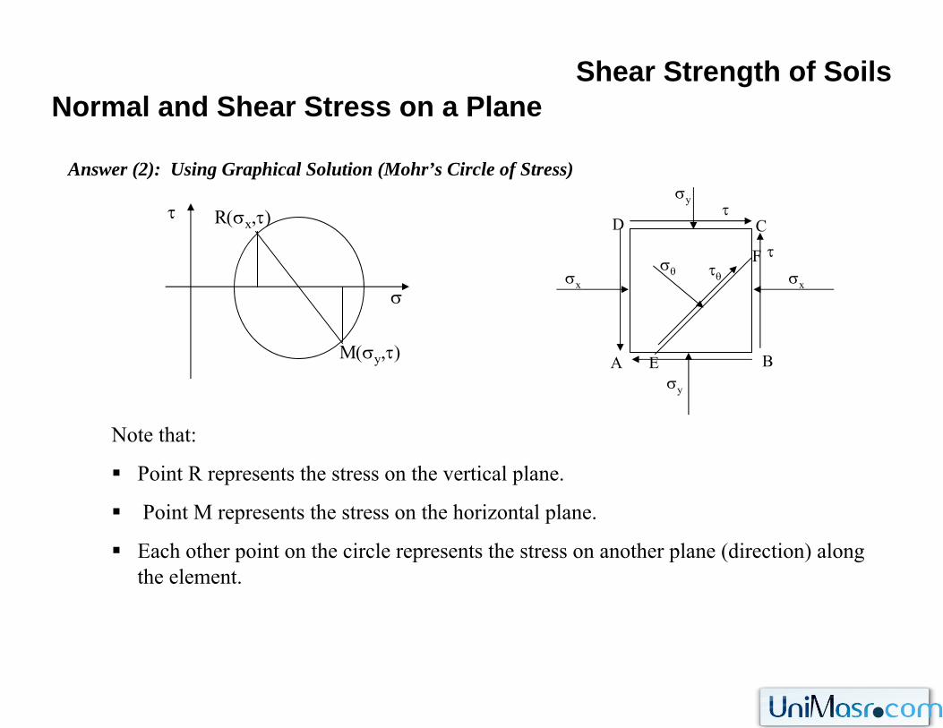
Answer (2): Using Graphical Solution (Mohr’s Circle of Stress)
σ
R(σx,τ)τ
M(σy,τ)
Note that:
Point R represents the stress on the vertical plane.
Point M represents the stress on the horizontal plane.
Each other point on the circle represents the stress on another plane (direction) along the element.
Shear Strength of SoilsNormal and Shear Stress on a Plane
D
σy
A
C
B
τ
σx σx
σy
τσθ τθ
E
F
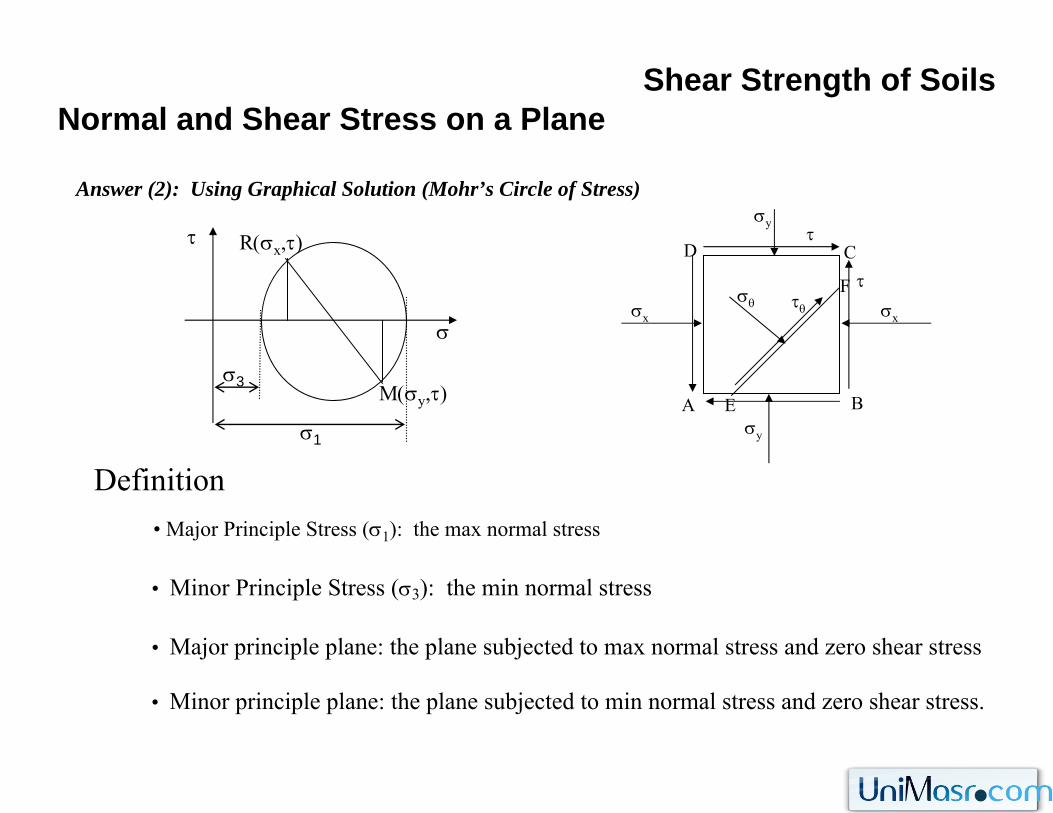
Answer (2): Using Graphical Solution (Mohr’s Circle of Stress)
σ
R(σx,τ)τ
M(σy,τ)
Definition
• Minor Principle Stress (σ3): the min normal stress
• Major principle plane: the plane subjected to max normal stress and zero shear stress
• Major Principle Stress (σ1): the max normal stress
σ1
σ3
• Minor principle plane: the plane subjected to min normal stress and zero shear stress.
Shear Strength of SoilsNormal and Shear Stress on a Plane
D
σy
A
C
B
τ
σx σx
σy
τσθ τθ
E
F
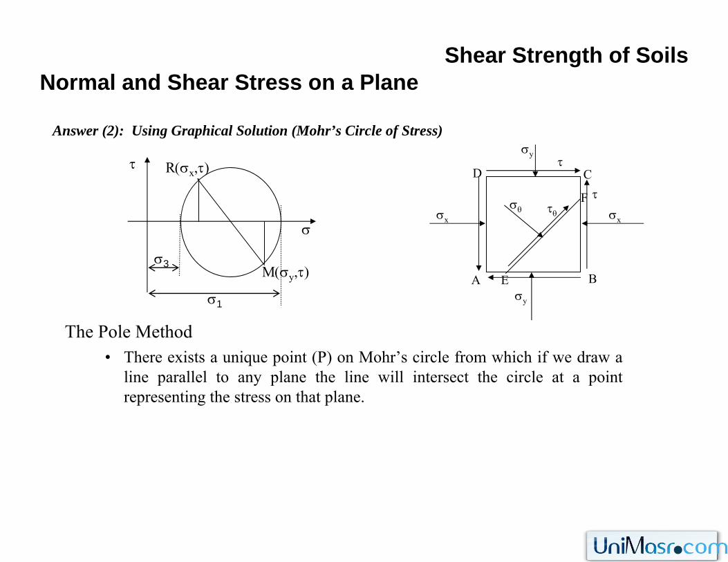
Answer (2): Using Graphical Solution (Mohr’s Circle of Stress)
σ
R(σx,τ)τ
M(σy,τ)
The Pole Method• There exists a unique point (P) on Mohr’s circle from which if we draw a
line parallel to any plane the line will intersect the circle at a point representing the stress on that plane.
σ1
σ3
σθ
τθ
P
Shear Strength of SoilsNormal and Shear Stress on a Plane
D
σy
A
C
B
τ
σx σx
σy
τσθ τθ
E
F
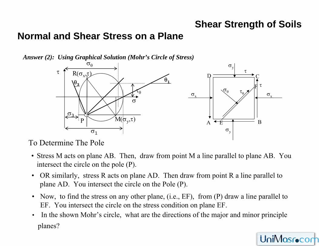
Answer (2): Using Graphical Solution (Mohr’s Circle of Stress)
σ
R(σx,τ)τ
M(σy,τ)
To Determine The Poleσ1
σ3
• Stress M acts on plane AB. Then, draw from point M a line parallel to plane AB. You intersect the circle on the pole (P).
• OR similarly, stress R acts on plane AD. Then draw from point R a line parallel to plane AD. You intersect the circle on the Pole (P).
• Now, to find the stress on any other plane, (i.e., EF), from (P) draw a line parallel to EF. You intersect the circle on the stress condition on plane EF.
θ1θ3
• In the shown Mohr’s circle, what are the directions of the major and minor principle planes?
Shear Strength of Soils
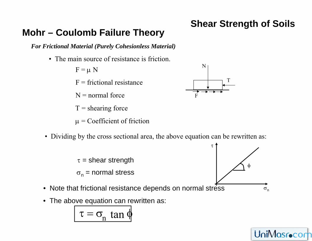
For Frictional Material (Purely Cohesionless Material)
Mohr – Coulomb Failure Theory
• The main source of resistance is friction.F = μ N
F = frictional resistance
N = normal force
Τ = shearing force
μ = Coefficient of friction
F
T
N
• Dividing by the cross sectional area, the above equation can be rewritten as:
nμσ=τ τ
σn
φτ = shear strength
σn = normal stress
• Note that frictional resistance depends on normal stress
• The above equation can rewritten as:
φσ=τ tann
Shear Strength of Soils
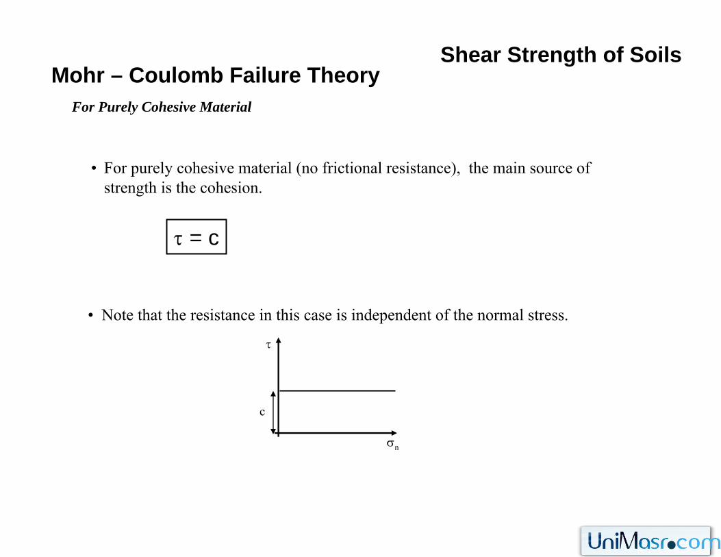
For Purely Cohesive Material
Mohr – Coulomb Failure Theory
• For purely cohesive material (no frictional resistance), the main source of strength is the cohesion.
τ = c
• Note that the resistance in this case is independent of the normal stress.
τ
σn
c
Shear Strength of Soils
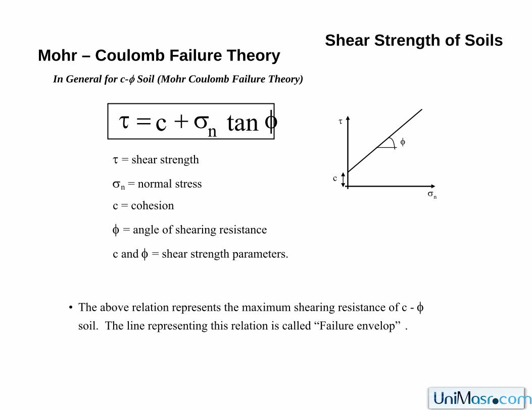
In General for c-φ Soil (Mohr Coulomb Failure Theory)
Mohr – Coulomb Failure Theory
• The above relation represents the maximum shearing resistance of c - φ soil. The line representing this relation is called “Failure envelop” .
τ = shear strength
σn = normal stress
c = cohesion
φ = angle of shearing resistance
c and φ = shear strength parameters.
τ
σn
φ
c
φσ+=τ tanc n
Shear Strength of SoilsMohr – Coulomb Failure Theory
τ
σn
φ
c1
2
3
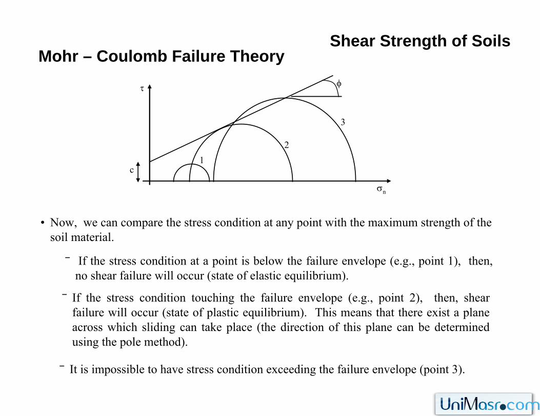
• Now, we can compare the stress condition at any point with the maximum strength of the soil material.
‾ If the stress condition at a point is below the failure envelope (e.g., point 1), then, no shear failure will occur (state of elastic equilibrium).
‾ If the stress condition touching the failure envelope (e.g., point 2), then, shear failure will occur (state of plastic equilibrium). This means that there exist a plane across which sliding can take place (the direction of this plane can be determined using the pole method).
‾ It is impossible to have stress condition exceeding the failure envelope (point 3).
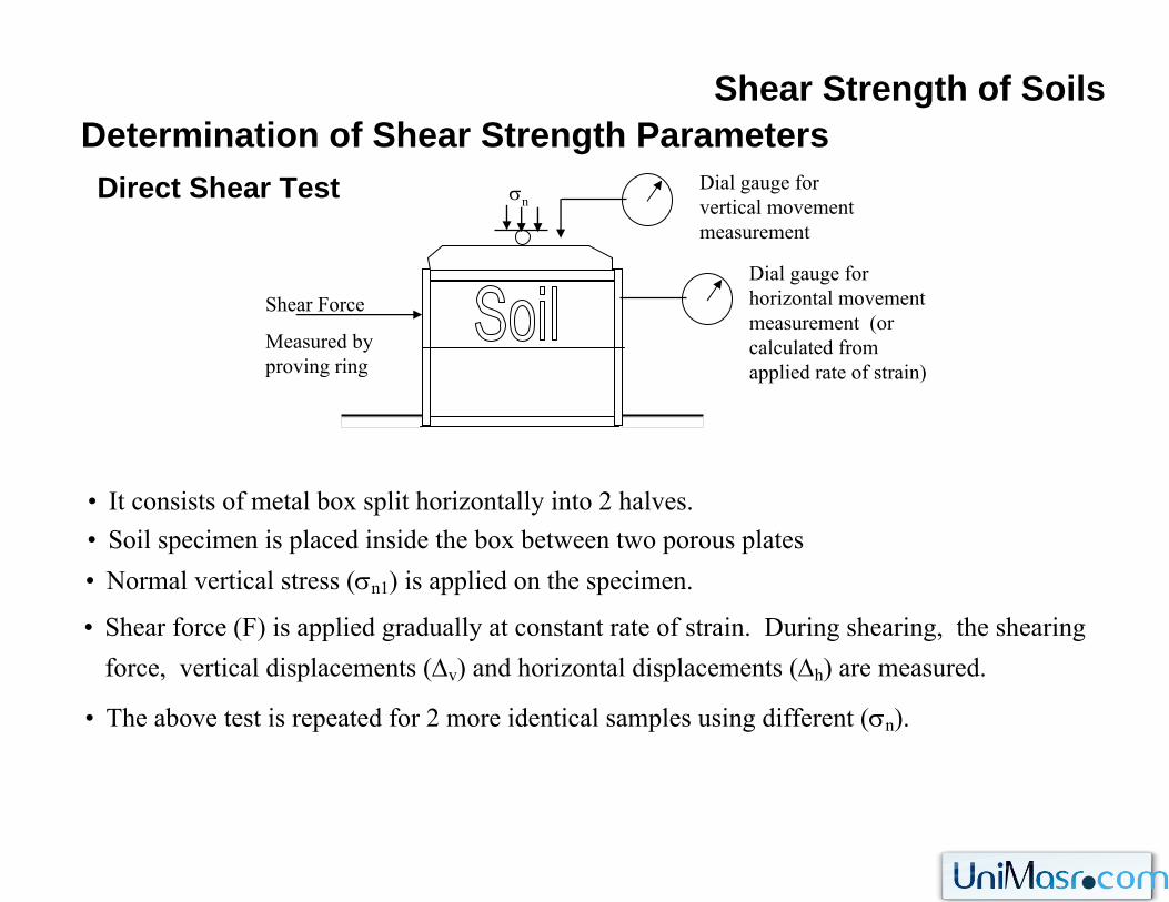
Shear Strength of SoilsDetermination of Shear Strength Parameters
• It consists of metal box split horizontally into 2 halves.
Direct Shear Test Dial gauge for vertical movement measurement
Shear Force
Measured by proving ring
σn
Dial gauge for horizontal movement measurement (or calculated from applied rate of strain)
• Soil specimen is placed inside the box between two porous plates• Normal vertical stress (σn1) is applied on the specimen.
• Shear force (F) is applied gradually at constant rate of strain. During shearing, the shearing force, vertical displacements (Δv) and horizontal displacements (Δh) are measured.
• The above test is repeated for 2 more identical samples using different (σn).
c
Shear Strength of SoilsDetermination of Shear Strength Parameters
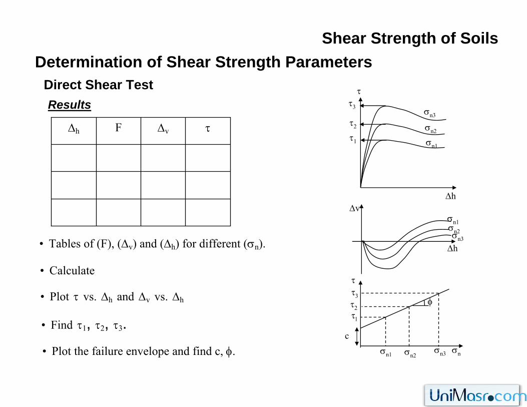
ResultsDirect Shear Test
• Tables of (F), (Δv) and (Δh) for different (σn).
• Calculate
• Plot τ vs. Δh and Δv vs. Δh
• Find τ1, τ2, τ3.
τΔvFΔhσn1
σn2
σn3
τ1
τ2
τ3
τ
ΔhΔv
Δhσn3
σn2
σn1
τ2
ττ3
τ1
σnσn3σn2σn1
φ
AF
=τ
• Plot the failure envelope and find c, φ.
Water under pressure
Shear Strength of SoilsDetermination of Shear Strength Parameters
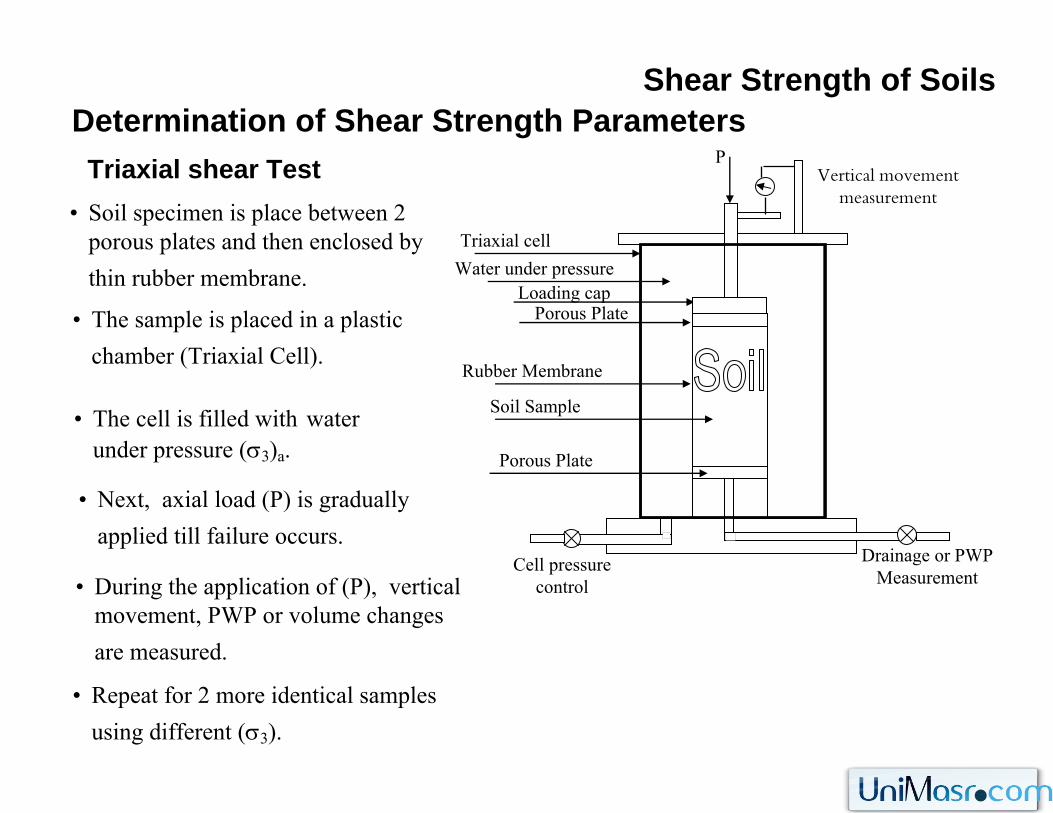
• Soil specimen is place between 2 porous plates and then enclosed by thin rubber membrane.
Triaxial shear Test
• The sample is placed in a plastic chamber (Triaxial Cell).
• The cell is filled with water under pressure (σ3)a.
• Next, axial load (P) is gradually applied till failure occurs.
• During the application of (P), vertical movement, PWP or volume changes are measured.
Drainage or PWP Measurement
PVertical movement
measurement
Triaxial cell
Rubber Membrane
Soil Sample
Loading capPorous Plate
Porous Plate
Cell pressure control
• Repeat for 2 more identical samples using different (σ3).
σ3
Shear Strength of SoilsDetermination of Shear Strength ParametersTriaxial shear Test
σ
τ
σ3σ
τ
σ3 σ1
σ3
σ3σ3
Δσσ3
σ3
σ3σ3
Δσ
σ1=σ3+Δσ
σ1=σ3+Δσ
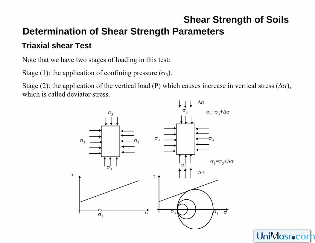
Note that we have two stages of loading in this test:
Stage (1): the application of confining pressure (σ3).
Stage (2): the application of the vertical load (P) which causes increase in vertical stress (Δσ), which is called deviator stress.
Δσb
Δσa
Shear Strength of SoilsDetermination of Shear Strength Parameters
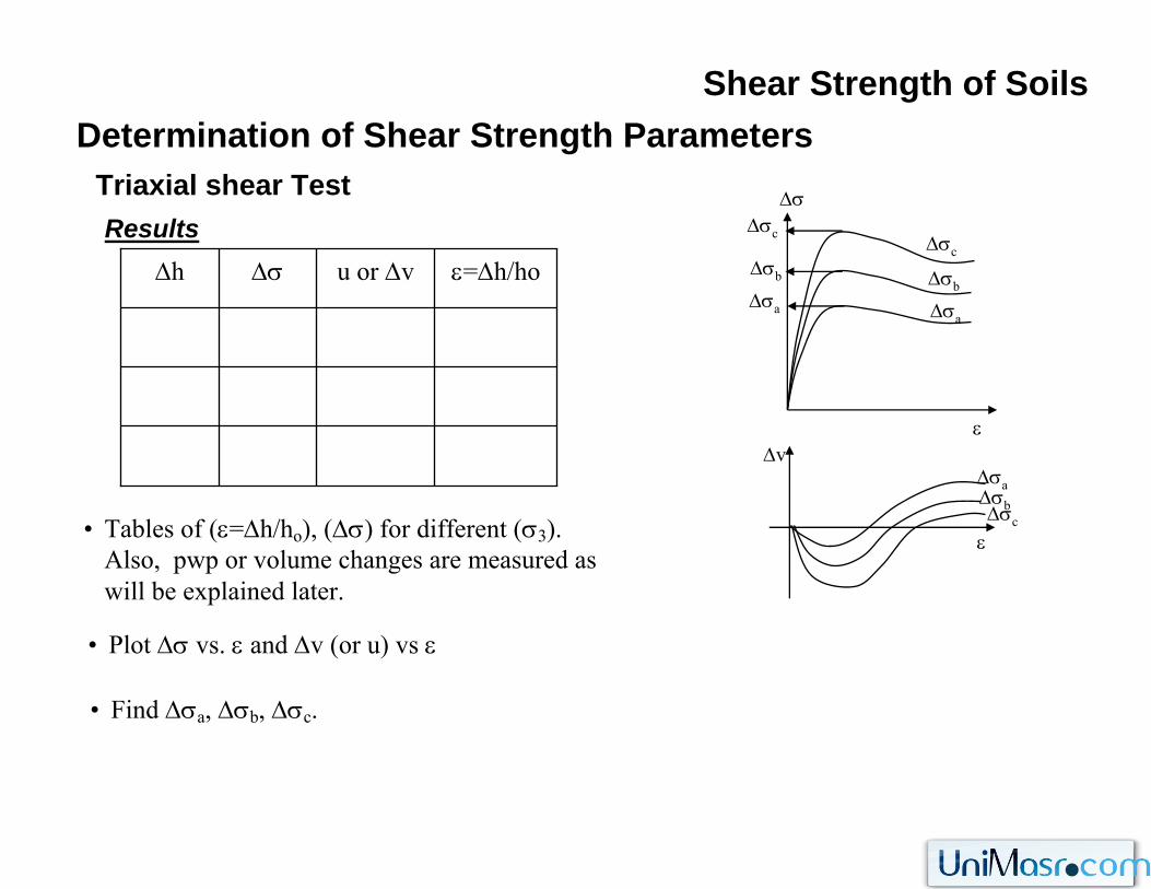
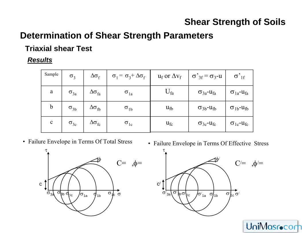
ResultsTriaxial shear Test
• Tables of (ε=Δh/ho), (Δσ) for different (σ3). Also, pwp or volume changes are measured as will be explained later.
• Plot Δσ vs. ε and Δv (or u) vs ε
• Find Δσa, Δσb, Δσc.
ε=Δh/hou or ΔvΔσΔhΔσa
Δσb
Δσc
Δσa
Δσb
Δσc
Δσ
εΔv
εΔσc
Shear Strength of SoilsDetermination of Shear Strength Parameters
ResultsTriaxial shear Test
• Failure Envelope in Terms Of Total Stress • Failure Envelope in Terms Of Effective Stress
σ1c-ufcσ3c-ufcufc
σ1b-ufbσ3b-ufbufb
σ1a-ufaσ3a-ufaUfa
σ’1fσ’3f = σ3-uuf or Δvf
σ/3c σ/
τ
c/
σ/3b σ/
1aσ/
3a
φ/
σ/1b σ/
1c
σ1cΔσfcσ3cc
σ1bΔσfbσ3bb
σ1aΔσfaσ3aa
σ1 = σ3+ ΔσfΔσfσ3Sample
σ3c σ
τ
cσ3b σ1a
σ3a
φ
σ1bσ1c
C= ,φ= C/= ,φ/=
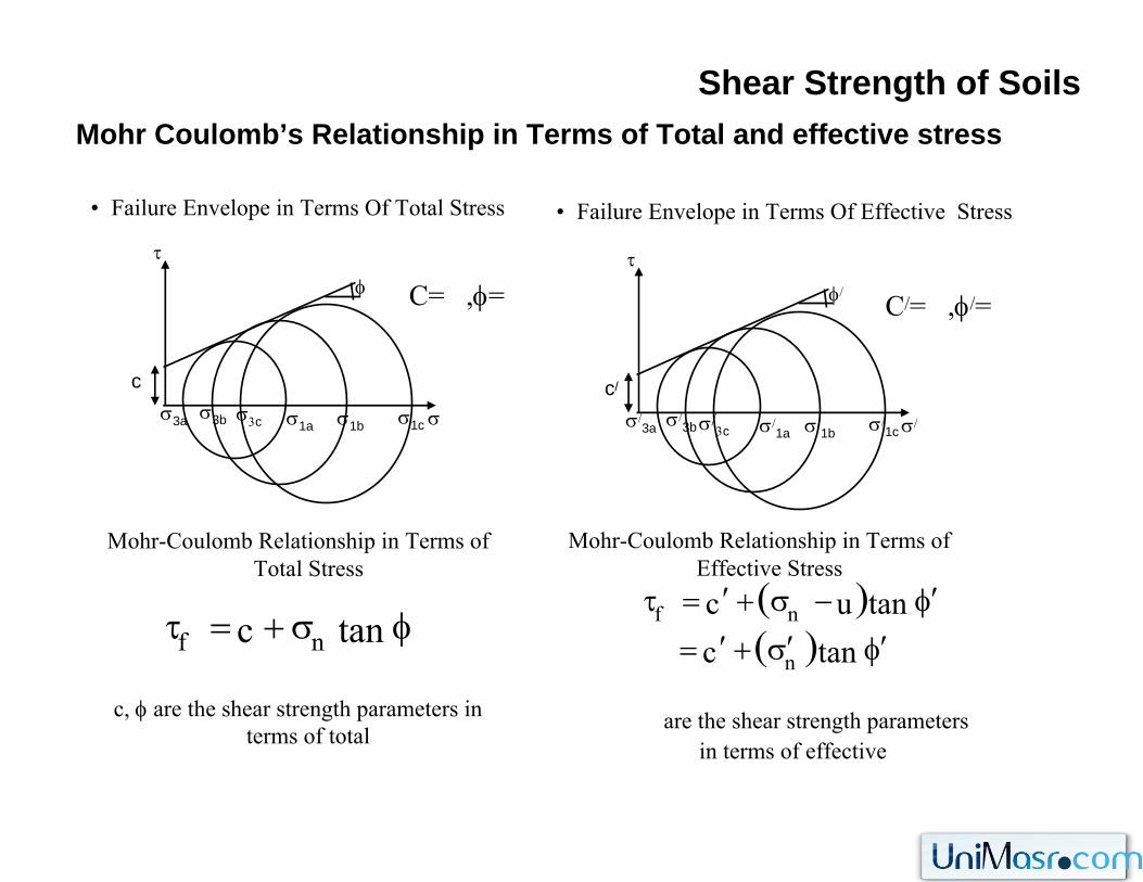
Shear Strength of SoilsMohr Coulomb’s Relationship in Terms of Total and effective stress
• Failure Envelope in Terms Of Total Stress • Failure Envelope in Terms Of Effective Stress
σ/3c σ/
τ
c/
σ/3b σ/
1aσ/
3a
φ/
σ/1b σ/
1cσ3c σ
τ
cσ3b σ1a
σ3a
φ
σ1b σ1c
C= ,φ= C/= ,φ/=
Mohr-Coulomb Relationship in Terms of Total Stress
c, φ are the shear strength parameters in terms of total
Mohr-Coulomb Relationship in Terms of Effective Stress
are the shear strength parameters in terms of effective
φ′′,c
φσ+=τ tanc nf( )( ) φ′σ′+′=
φ′−σ+′=τ
tanctanuc
n
nf
Shear Strength of SoilsSources of Soil Strength
• The sources of soil strength are:- Friction between particles,- Interlocking of Particles,- Attraction forces between particles due to electrical charges on their surfaces.
• Coarse grained soils (sand and gravel) are bulky and have small specific surface (surface area /
mass). Then, the main sources of strength are friction and interlocking.
• Fine grained soils are very small, sheet like, have high specific surface, with electro-chemical charges on their surfaces, and have highly developed structure. Therefore, The main source of
resistance are attraction forces between particles, and to some extend interlocking.
• Shearing resistance is the result of resistance to movement at inter-particle contacts by the above sources. Any factor that increase inter-particle resistance increases shearing resistance.
• It is obvious that σ/ results in soil particles becoming more closely packed, and thus increases the above sources of strength. Therefore, shearing resistance increases with the increase of effective stress.
• Shearing resistance is function of effective stress
Shear Strength of SoilsShear Strength of Saturated Soil
• The deformations associated with shearing of saturated soil result in development of excess pwp.
• In soils with low permeability (Silt, clay) and if the rate of loading is fast, the excess pwp does not dissipate quickly (during shear). The strength of the soil in this case is called “the undrainedstrength” and the shear strength parameters defining Mohr-Coulomb failure envelope are called
“the undrained parameters”.
• In soils with low permeability (Silt, clay) and if the rate of loading is slow to allow the dissipation of the generated pwp during shear, then, the strength of the soil is called “the drained strength” and the shear strength parameters defining Mohr-Coulomb failure envelope are
called “the drained parameters” .
• for saturated low permeability soil, shear strength and its parameters depend on the drainage
condition (i.e., depend on the rate of loading).
• However, for soils with high permeability (sand and gravel), excess pwp is drained instantaneously and the strength will always be in drained condition.
Shear Strength of SoilsTypes of Shear Tests
• Note that in the direct shear test we have 2 stages of loading:
Application of normal stress (σn)
Application of shearing stress (τ)
• Note also that in the triaxial test we have 2 stages of loading:
Application of confining stress (σ3)
Application of deviator stress which cause shearing (Δσ or (σ1-σ3)).
• In both tests, the loading can be applied using one of the following three methods (i.e., we have
three types of tests that can be performed).
Shear Strength of SoilsTypes of Shear Tests
• Unconsolidated- Undrained test (U-U test),The sample is not allowed to be consolidated under the first stage of loading (σn or σ3).
The sample is not allowed to be drained during the second stage of loading (τ or σ3).
• Consolidated- Undrained test (C-U test),
The sample is allowed to be consolidated under the first stage of loading (σn or σ3).
The sample is not allowed to be drained during the second stage of loading (τ or σ3).
• Consolidated- Undrained test (C-U test),
The sample is allowed to be consolidated under the first stage of loading (σn or σ3).
The sample is allowed to be drained during the second stage of loading (τ or σ3).
Shear Strength of SoilsTypes of Shear Tests
• To consolidate the sample under the first stage of loading, leave the sample sufficient time
under (σn or σ3) to allow consolidation.
• To drain the sample during the second stage of loading, apply shearing (τ or Δσ) very slowly
to allow excess pwp to be dissipated.
• Note that for clays, k is very small and hence we can control the type of the test by controlling
the rate of loading as explained above.
• However, for sands, k is high and hence the excess pwp due to loading will dissipate quickly.
Hence, the sample is essentially drained and the test is usually CD.
σ3
σ3
σ3
Δσ
σ1=σ3+Δσ
σ1=σ3+Δσ
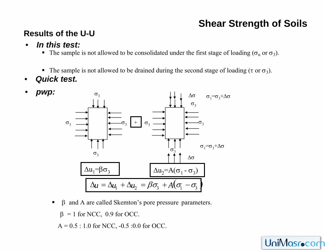
Shear Strength of SoilsResults of the U-U• In this test:
The sample is not allowed to be consolidated under the first stage of loading (σn or σ3).
The sample is not allowed to be drained during the second stage of loading (τ or σ3).• Quick test.• pwp:
σ3
σ3σ3
σ3
σ3
Δσ
+
Δu1=βσ3 Δu2=Α(σ1 - σ3)
β and A are called Skemton’s pore pressure parameters.
β = 1 for NCC, 0.9 for OCC.
A = 0.5 : 1.0 for NCC, -0.5 :0.0 for OCC.
( )31321 σσβσ −+=Δ+Δ=Δ Auuu
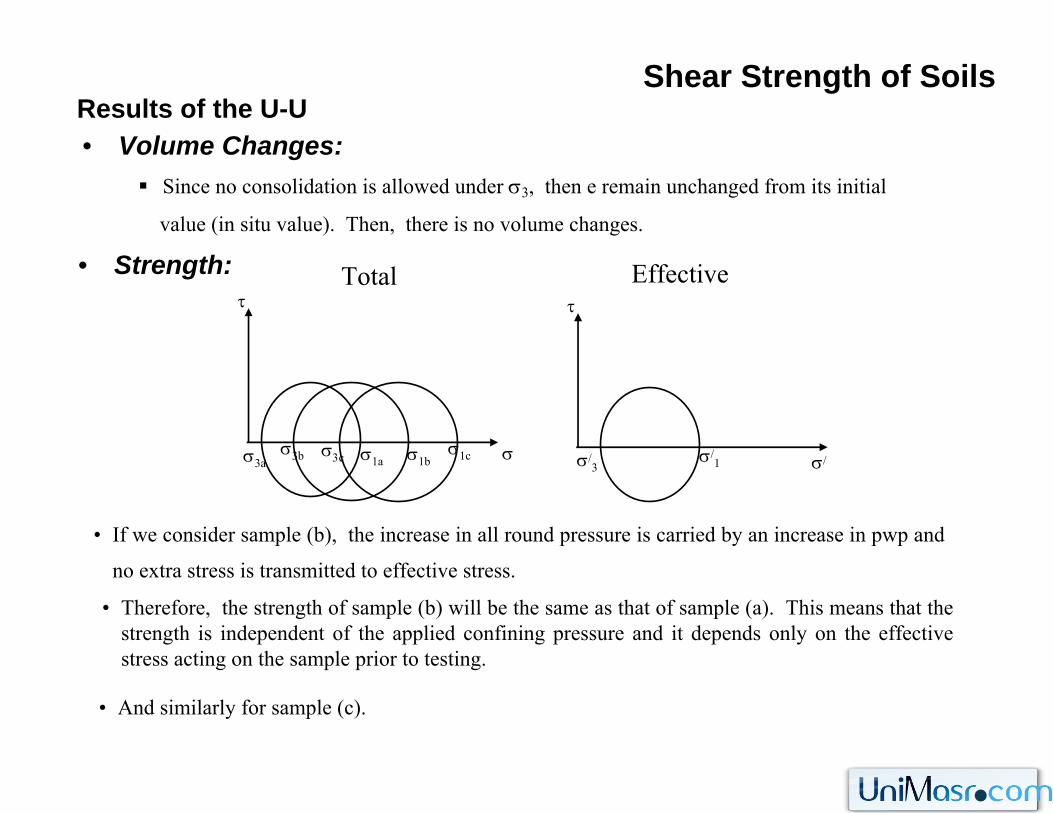
Shear Strength of SoilsResults of the U-U• Volume Changes:
Since no consolidation is allowed under σ3, then e remain unchanged from its initial
value (in situ value). Then, there is no volume changes.
• Strength:
σ3cσ3b σ1aσ3a σ1bσ1c
τ
σ/3
Effective
σ/1 σ/
τTotal
σ
• If we consider sample (b), the increase in all round pressure is carried by an increase in pwp and
no extra stress is transmitted to effective stress.
• Therefore, the strength of sample (b) will be the same as that of sample (a). This means that the strength is independent of the applied confining pressure and it depends only on the effective stress acting on the sample prior to testing.
• And similarly for sample (c).
Shear Strength of SoilsResults of the U-U
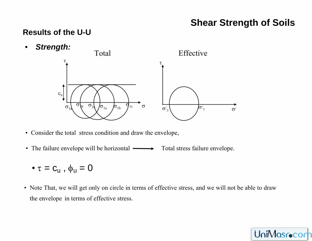
• Strength:
cu
σ3cσ3b σ1aσ3a σ1bσ1c
τ
σ/3
Effective
σ/1 σ/
τTotal
σ
• τ = cu , φu = 0
• The failure envelope will be horizontal Total stress failure envelope.
• Note That, we will get only on circle in terms of effective stress, and we will not be able to draw
the envelope in terms of effective stress.
• Consider the total stress condition and draw the envelope,
σ3
σ3
σ3
Δσ
σ1=σ3+Δσ
σ1=σ3+Δσ
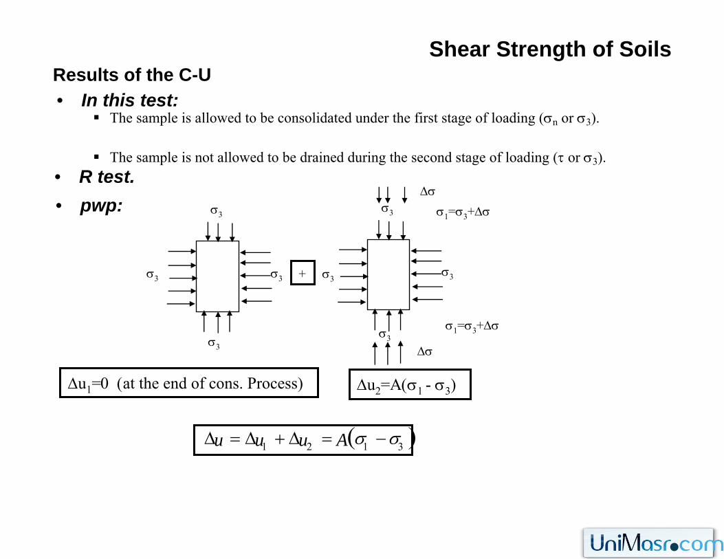
Shear Strength of SoilsResults of the C-U• In this test:
The sample is allowed to be consolidated under the first stage of loading (σn or σ3).
The sample is not allowed to be drained during the second stage of loading (τ or σ3).• R test.• pwp:
σ3
σ3σ3
σ3
σ3
Δσ
+
Δu1=0 (at the end of cons. Process) Δu2=Α(σ1 - σ3)
( )3121 σσ −=Δ+Δ=Δ Auuu
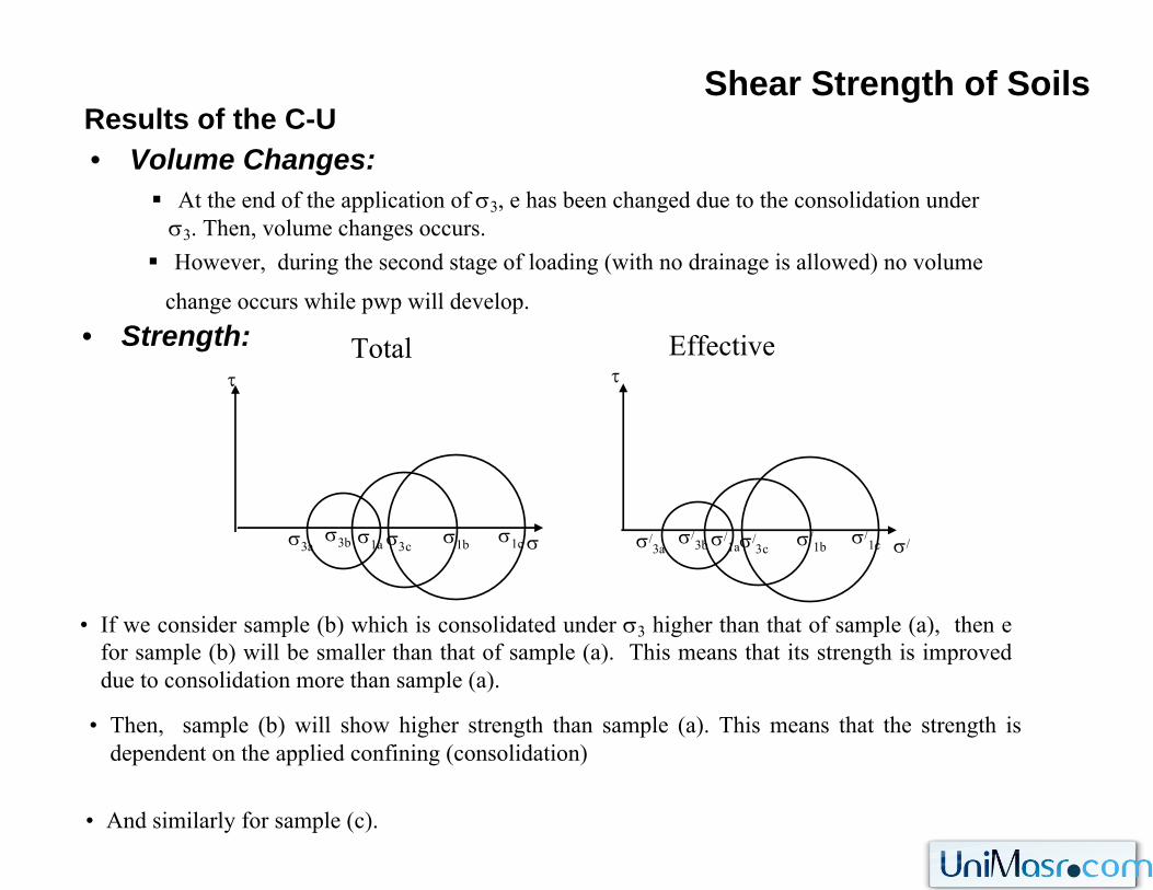
Shear Strength of SoilsResults of the C-U• Volume Changes:
At the end of the application of σ3, e has been changed due to the consolidation underσ3. Then, volume changes occurs.
• Strength: EffectiveTotal
• If we consider sample (b) which is consolidated under σ3 higher than that of sample (a), then e for sample (b) will be smaller than that of sample (a). This means that its strength is improved due to consolidation more than sample (a).
• Then, sample (b) will show higher strength than sample (a). This means that the strength is dependent on the applied confining (consolidation)
• And similarly for sample (c).
However, during the second stage of loading (with no drainage is allowed) no volume
change occurs while pwp will develop.
σσ3b σ1b
τ
σ1aσ3aσ1cσ3c σ/
3b σ/1bσ/
3cσ/
1c
τ
σ/1aσ/
3a σ/
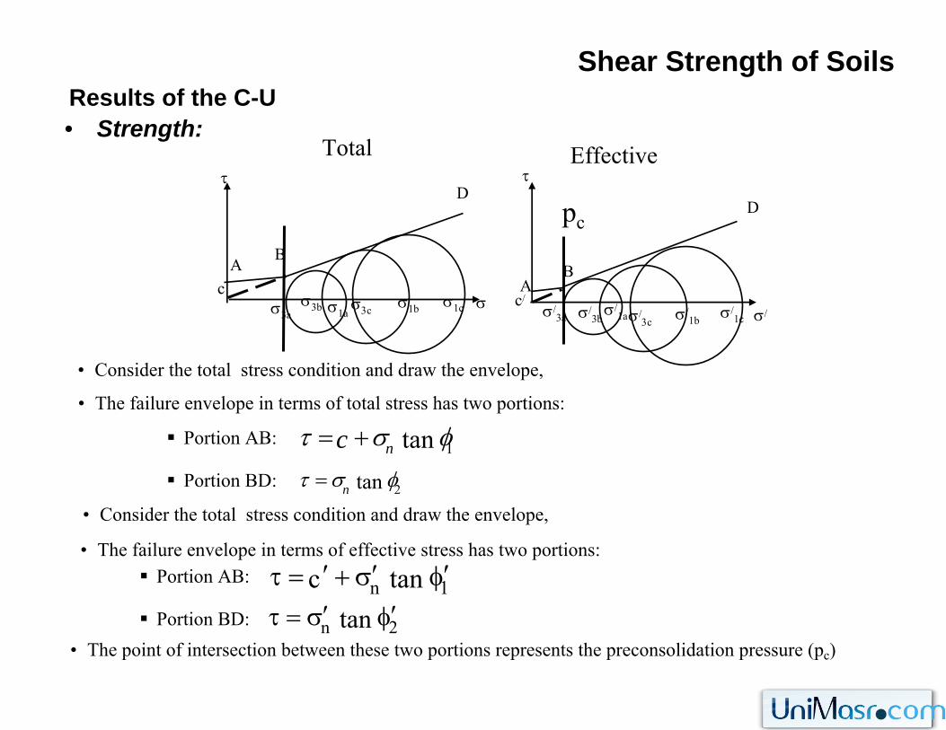
Shear Strength of SoilsResults of the C-U• Strength:
EffectiveTotal
• The failure envelope in terms of total stress has two portions:
σc
σ3b σ1b
τ
σ1aσ3aσ1cσ3c
c/σ/
3b σ/1bσ/
3cσ/
1c
pc
τ
σ/1aσ/
3a σ/
• Consider the total stress condition and draw the envelope,
• Consider the total stress condition and draw the envelope,
BA
D
Portion AB:
Portion BD:
• The failure envelope in terms of effective stress has two portions:Portion AB:
Portion BD:
AB
D
• The point of intersection between these two portions represents the preconsolidation pressure (pc)
2tan φστ n=
1tan φστ nc +=
1n tanc φ′σ′+′=τ
2n tan φ′σ′=τ
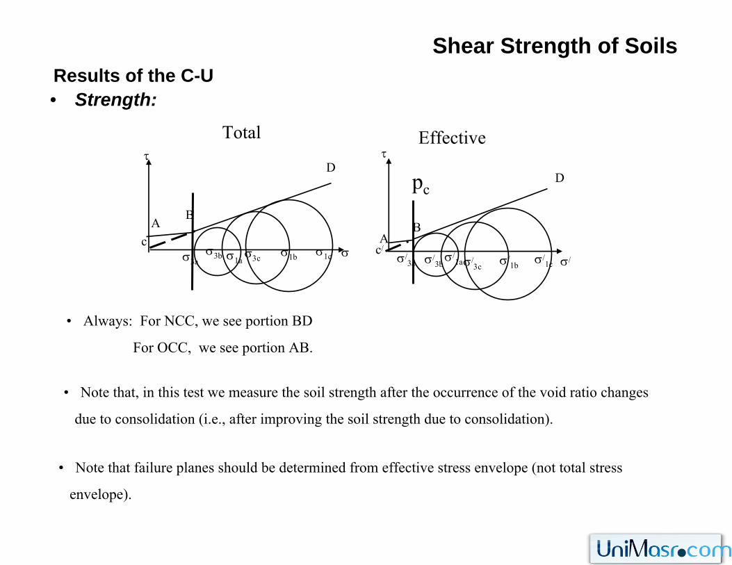
Shear Strength of SoilsResults of the C-U• Strength:
EffectiveTotal
σc
σ3b σ1b
τ
σ1aσ3aσ1cσ3c
c/σ/
3b σ/1bσ/
3cσ/
1c
pc
τ
σ/1aσ/
3a σ/
BA
D
AB
D
• Always: For NCC, we see portion BD
For OCC, we see portion AB.
• Note that, in this test we measure the soil strength after the occurrence of the void ratio changes
due to consolidation (i.e., after improving the soil strength due to consolidation).
• Note that failure planes should be determined from effective stress envelope (not total stress
envelope).
σ3
σ3
σ3
Δσ
σ1=σ3+Δσ
σ1=σ3+Δσ
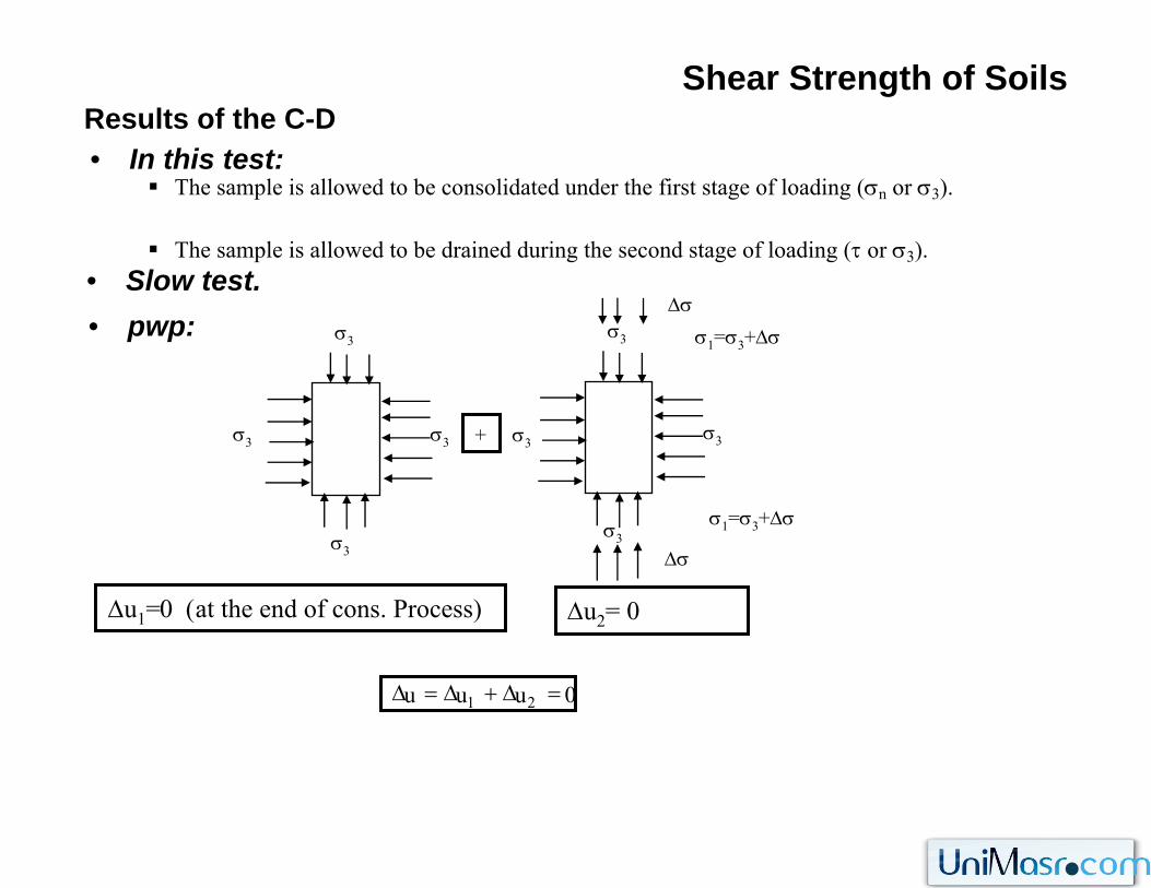
Shear Strength of SoilsResults of the C-D• In this test:
The sample is allowed to be consolidated under the first stage of loading (σn or σ3).
The sample is allowed to be drained during the second stage of loading (τ or σ3).• Slow test.• pwp:
σ3
σ3σ3
σ3
σ3
Δσ
+
Δu1=0 (at the end of cons. Process) Δu2= 0
0uuu 21 =Δ+Δ=Δ
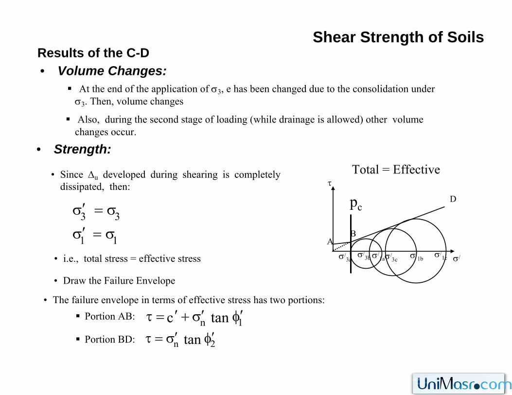
Shear Strength of SoilsResults of the C-D• Volume Changes:
At the end of the application of σ3, e has been changed due to the consolidation underσ3. Then, volume changes
• Strength:Total = Effective• Since Δu developed during shearing is completely
dissipated, then:
• i.e., total stress = effective stress
Also, during the second stage of loading (while drainage is allowed) other volume changes occur.
σ/3b σ/
1bσ/3c
σ/1c
τ
σ/1aσ/
3a σ/
pc
AB
D
• Draw the Failure Envelope
• The failure envelope in terms of effective stress has two portions:Portion AB:
Portion BD:1n tanc φ′σ′+′=τ
2n tan φ′σ′=τ
11
33
σ=σ′σ=σ′
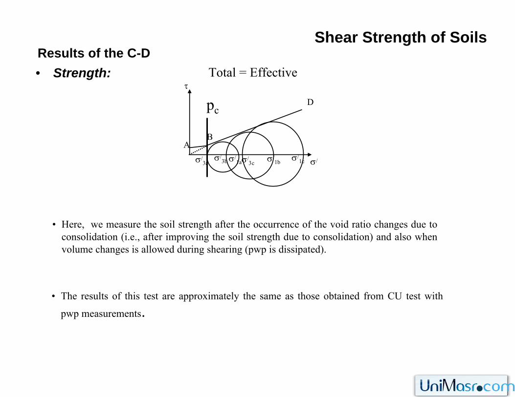
Shear Strength of SoilsResults of the C-D• Strength:
τ
σ/1aσ/
3a σ/
Total = Effective
σ/3b σ/
1bσ/3c
σ/1c
pc
AB
D
• Here, we measure the soil strength after the occurrence of the void ratio changes due to consolidation (i.e., after improving the soil strength due to consolidation) and also when volume changes is allowed during shearing (pwp is dissipated).
• The results of this test are approximately the same as those obtained from CU test with
pwp measurements.
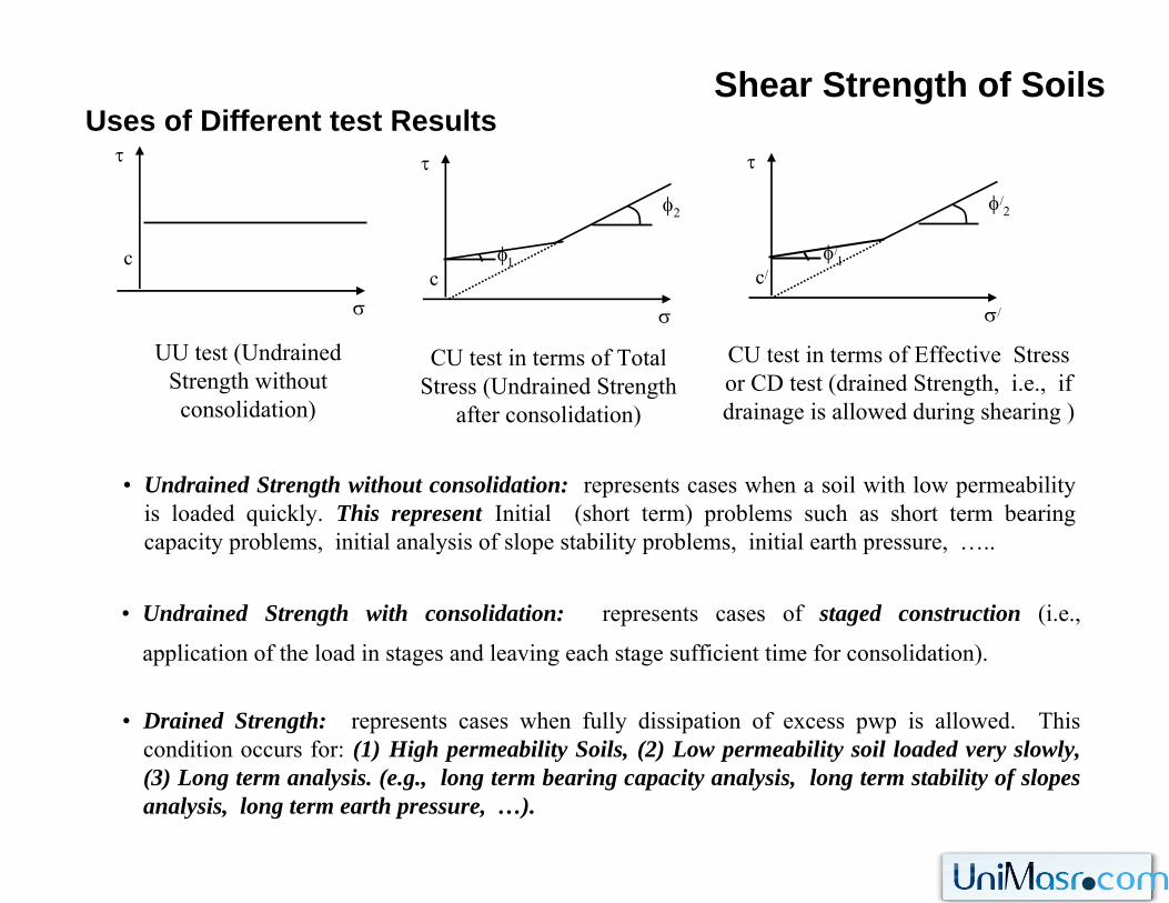
Shear Strength of SoilsUses of Different test Results
• Undrained Strength without consolidation: represents cases when a soil with low permeability is loaded quickly. This represent Initial (short term) problems such as short term bearing capacity problems, initial analysis of slope stability problems, initial earth pressure, …..
σ
τ
c
σ
τ
φ2
φ1c
σ/
τ
φ/2
φ/1
c/
UU test (UndrainedStrength without consolidation)
CU test in terms of Total Stress (Undrained Strength
after consolidation)
CU test in terms of Effective Stress or CD test (drained Strength, i.e., if drainage is allowed during shearing )
• Undrained Strength with consolidation: represents cases of staged construction (i.e.,
application of the load in stages and leaving each stage sufficient time for consolidation).
• Drained Strength: represents cases when fully dissipation of excess pwp is allowed. This condition occurs for: (1) High permeability Soils, (2) Low permeability soil loaded very slowly, (3) Long term analysis. (e.g., long term bearing capacity analysis, long term stability of slopes analysis, long term earth pressure, …).
Shear Strength of SoilsDrained and Undrained Conditions• Drained Condition: is a limiting condition under which there is no excess pwp in the
soil.
• In drained condition: we use effective stress analysis with effective shear strength parameters (c/ , φ/)
• It can develop: (1) if the rate of loading is sufficient ally slow such that no Δu develop.
High k soil
(2) If long time elapsed such that Δu dissipate,
long term in high or low k soil
• Undrained Condition: is a limiting condition under which no pore water movement take places and excess is generated.
• This condition is often assumed for low k soil in short term (just after construction).
• In undrained condition: we use total stress analysis with total shear strength parameters (cu, φu = 0)
• What is the critical condition?
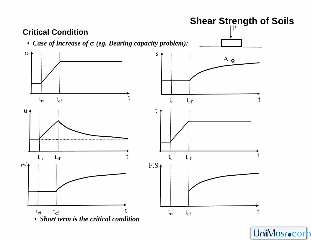
Shear Strength of SoilsCritical Condition
• Case of increase of σ (eg. Bearing capacity problem):
t
σ
tci tcf
A
P
t
u
tci tcf
t
σ/
tci tcf
t
s
tci tcf
t
τ
tci tcf
t
F.S
tci tcf• Short term is the critical condition
Shear Strength of SoilsCritical Condition
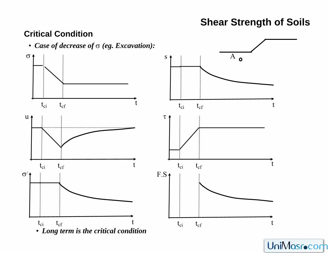
• Case of decrease of σ (eg. Excavation):
t
σ
tci tcf
t
u
tci tcf
t
σ/
tci tcf
t
s
tci tcf
t
τ
tci tcf
t
F.S
tci tcf• Long term is the critical condition
A
Δh
Load
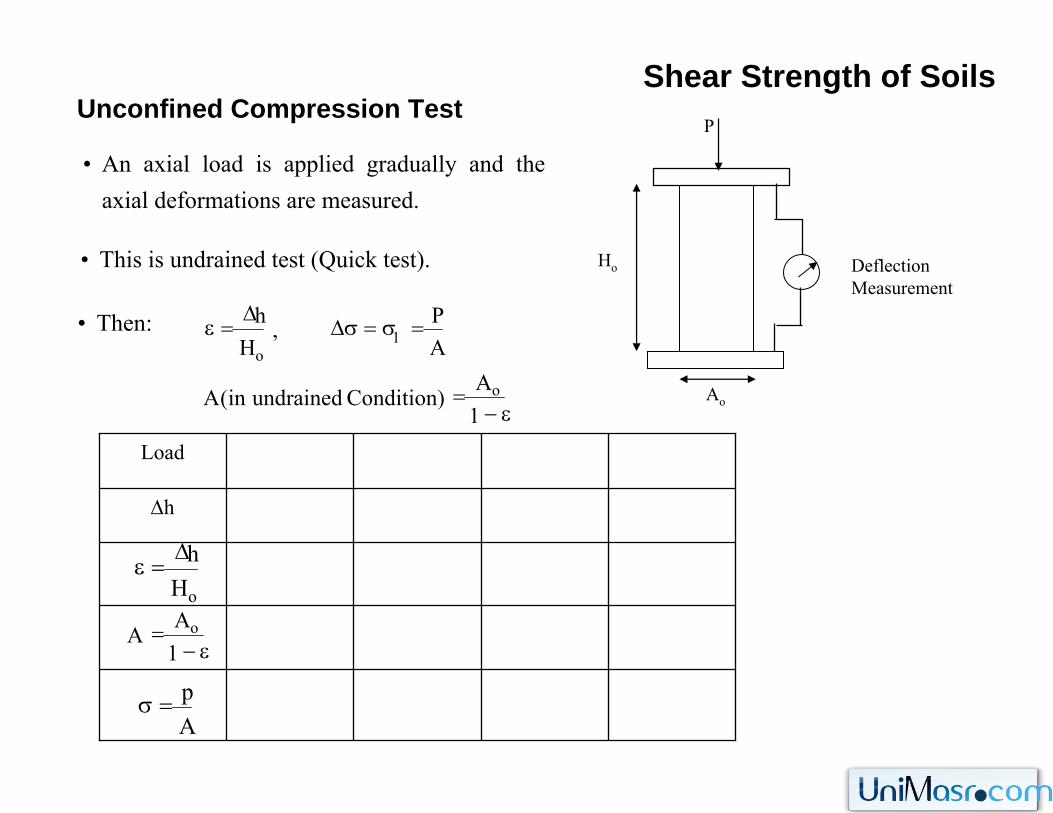
Shear Strength of SoilsUnconfined Compression Test
• An axial load is applied gradually and the axial deformations are measured.
• This is undrained test (Quick test).
• Then:
Deflection Measurement
P
Ho
Ao
oHhΔ
=ε
ε−=
1A
A o
Ap=σ
ε−=
=σ=σΔΔ
=ε
1A
)Conditionundrainedin(A
AP,
Hh
o
1o
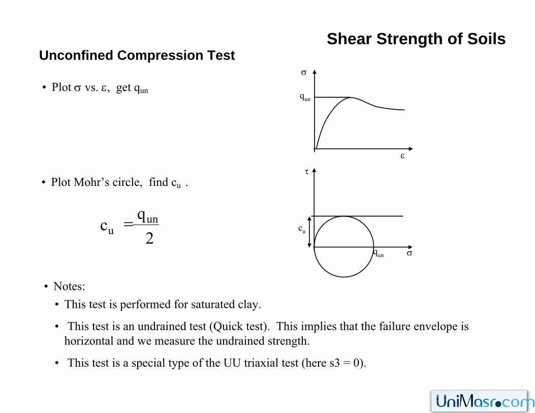
Shear Strength of SoilsUnconfined Compression Test
• Plot σ vs. ε, get qun
• Plot Mohr’s circle, find cu .
• Notes:
σ
ε
qun
σ
τ
cu
qun
• This test is performed for saturated clay.
• This test is an undrained test (Quick test). This implies that the failure envelope is horizontal and we measure the undrained strength.
• This test is a special type of the UU triaxial test (here s3 = 0).
2q
c unu =
Shear Strength of Soils
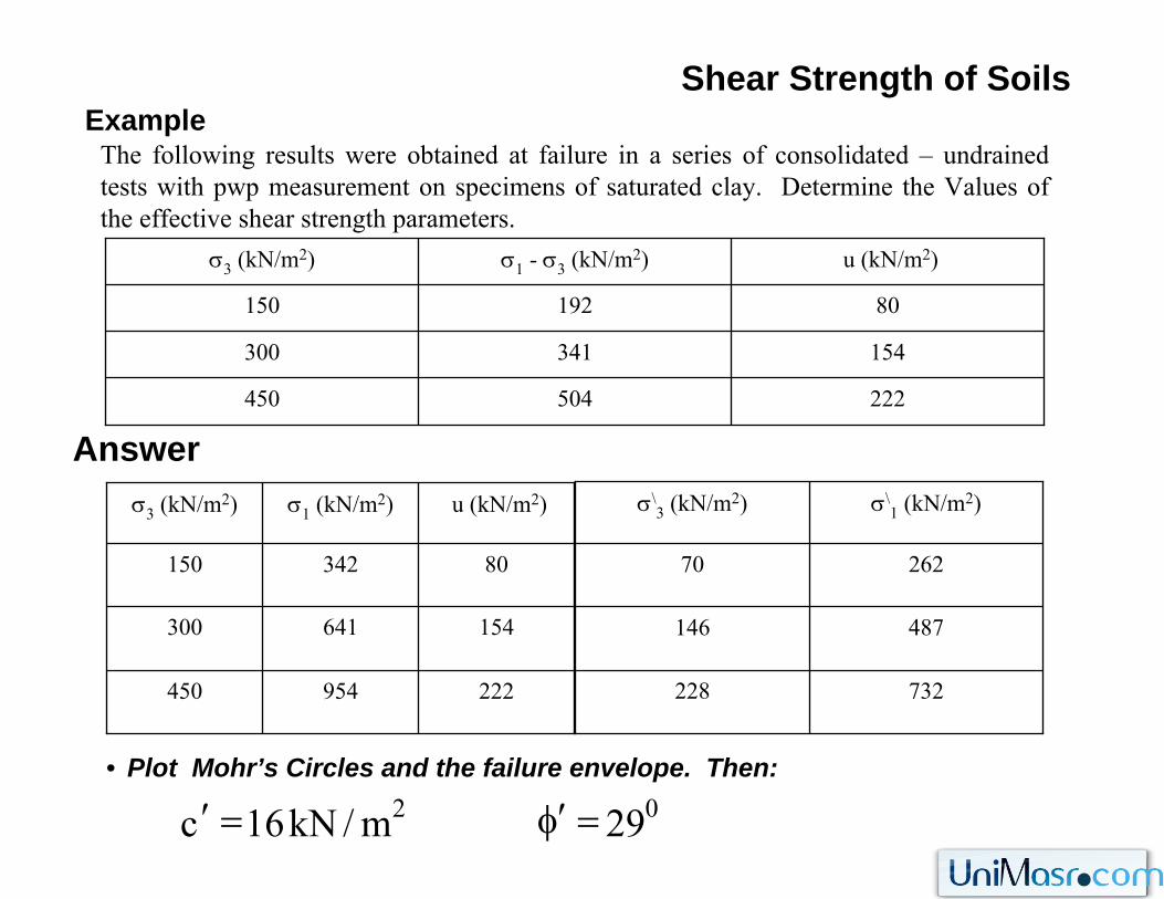
222504450
154341300
80192150
u (kN/m2)σ1 - σ3 (kN/m2)σ3 (kN/m2)
222954450
154641300
80342150
u (kN/m2)σ1 (kN/m2)σ3 (kN/m2)
ExampleThe following results were obtained at failure in a series of consolidated – undrainedtests with pwp measurement on specimens of saturated clay. Determine the Values of the effective shear strength parameters.
• Plot Mohr’s Circles and the failure envelope. Then:
Answer
732228
487146
26270
σ\1 (kN/m2)σ\
3 (kN/m2)
02 29m/kN16c =φ′=′
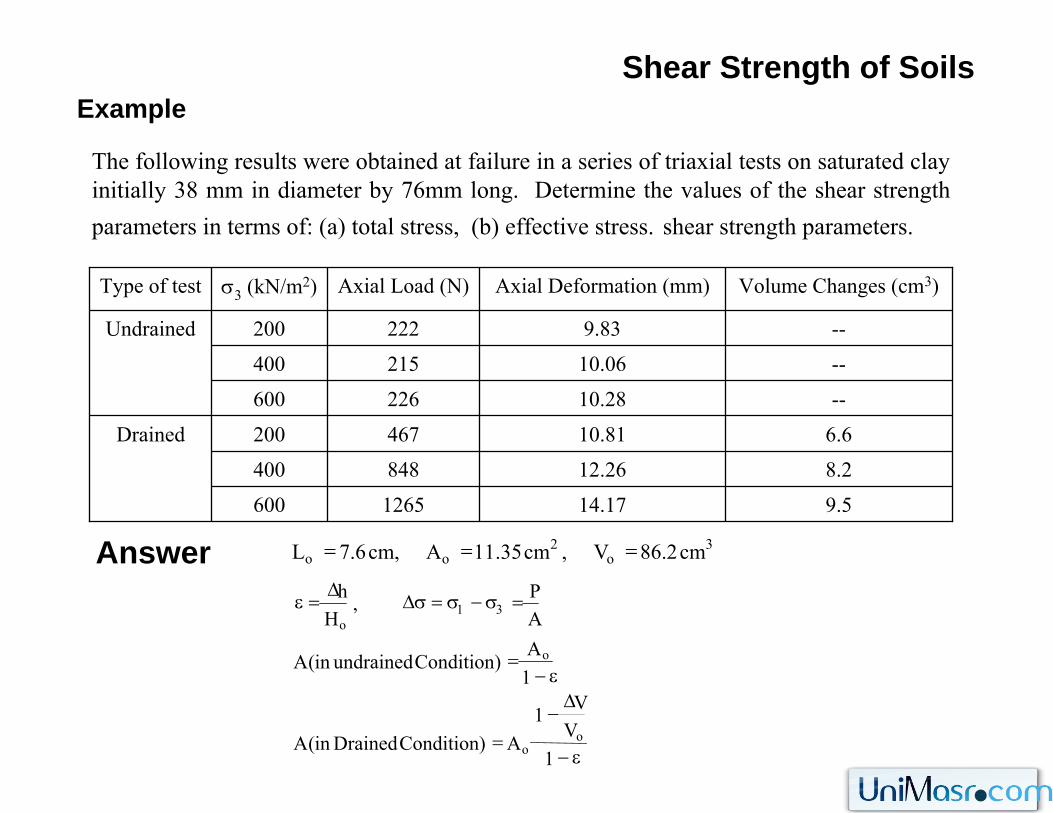
Shear Strength of SoilsExample
The following results were obtained at failure in a series of triaxial tests on saturated clay initially 38 mm in diameter by 76mm long. Determine the values of the shear strength parameters in terms of: (a) total stress, (b) effective stress. shear strength parameters.
Answer9.514.171265600
8.212.26848400
6.610.81467200Drained
--10.28226600
--10.06215400
--9.83222200Undrained
Volume Changes (cm3)Axial Deformation (mm)Axial Load (N)σ3 (kN/m2)Type of test
ε−
Δ−
=
ε−=
=σ−σ=σΔΔ
=ε
1V
V1A)ConditionDrainedin(A
1A)Conditionundrainedin(A
AP,
Hh
oo
o
31o
3o
2oo cm2.86V,cm35.11A,cm6.7L ===
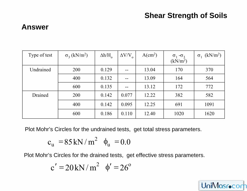
Shear Strength of SoilsAnswer
1620102012.400.1100.186600
109169112.250.0950.142400
58238212.220.0770.142200Drained
77217213.12--0.135600
56416413.09--0.132400
37017013.04--0.129200Undrained
σ1 (kN/m2)σ1 -σ3(kN/m2)
A(cm2)ΔV/VoΔh/Hoσ3 (kN/m2)Type of test
Plot Mohr’s Circles for the undrained tests, get total stress parameters.
Plot Mohr’s Circles for the drained tests, get effective stress parameters.
0.0m/kN85c u2
u =φ=
o2 26m/kN20c =φ′=′
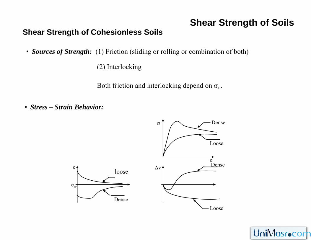
Shear Strength of SoilsShear Strength of Cohesionless Soils
• Sources of Strength: (1) Friction (sliding or rolling or combination of both)
(2) Interlocking
Both friction and interlocking depend on σn.
• Stress – Strain Behavior:
ε
σ Dense
Loose
Loose
DenseΔve
Dense
ecr
loose
Shear Strength of SoilsShear Strength of Cohesionless Soils
• Dense sand has high initial modulus, the stress reaches a peak value and then dcreaseto a residual value.
• Loose sand has lower initial modulus, there is no peak, the ultimate strength is reached at high strain.
• The extra strength for dense sand is attributed to the greater degree of interlocking. This interlocking is overcome as shearing displacement increased.
• During shear, dense sand tends to dilate (expand) while loose sand tends to compress. Both dense and loose sand attain approximately the same void ratio (the critical void ratio) at sufficiently high strain.
• If cohessionless soil is initially at its critical void ratio, no volume changes occurs during shear.
Shear Strength of SoilsShear Strength of Cohesionless Soils
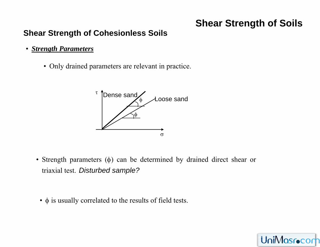
• Strength Parameters
• Only drained parameters are relevant in practice.
• Strength parameters (φ) can be determined by drained direct shear or triaxial test. Disturbed sample?
• φ is usually correlated to the results of field tests.
σ
τ
φ
Loose sandφDense sand
Shear Strength of SoilsShear Strength of Cohesionless Soils
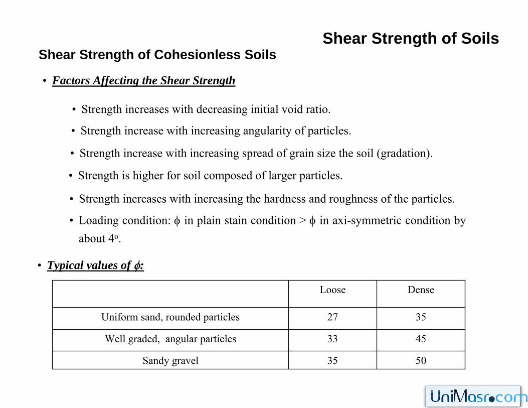
• Factors Affecting the Shear Strength
• Strength increases with decreasing initial void ratio.
• Strength increase with increasing angularity of particles.
• Strength increase with increasing spread of grain size the soil (gradation).
• Strength is higher for soil composed of larger particles.
• Strength increases with increasing the hardness and roughness of the particles.
• Loading condition: φ in plain stain condition > φ in axi-symmetric condition by about 4o.
• Typical values of φ:
5035Sandy gravel
4533Well graded, angular particles
3527Uniform sand, rounded particles
DenseLoose
Shear Strength of SoilsShear Strength of Saturated Cohesive Soils
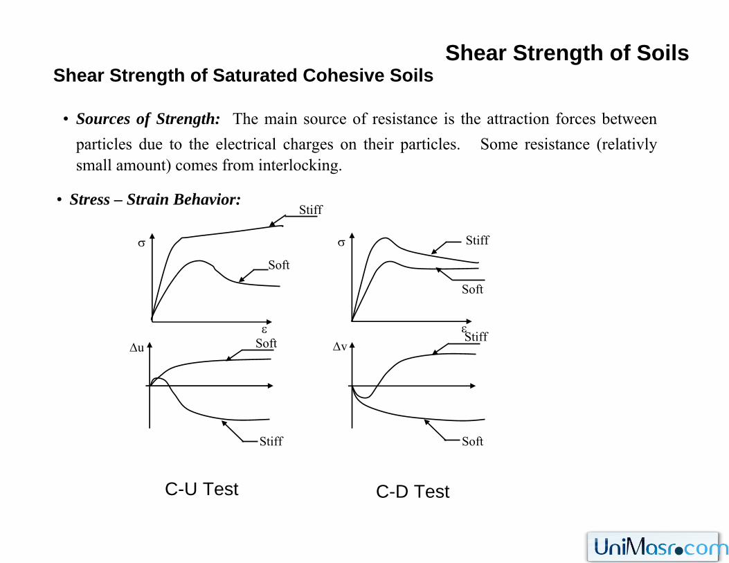
• Sources of Strength: The main source of resistance is the attraction forces betweenparticles due to the electrical charges on their particles. Some resistance (relativlysmall amount) comes from interlocking.
• Stress – Strain Behavior:
ε
σ
Stiff
Soft
Stiff
Δu
C-U Test
Soft
ε
σ
Stiff
Soft
Δv
Stiff
Soft
C-D Test
Shear Strength of SoilsShear Strength of Saturated Cohesive Soils
• Factors Affecting the Shear Strength
• Drainage condition.
• Stress history: the higher the preconsolidation pressure, the higher the soil strength.
• Water content: the higher the water content, the lower the shear.
• Void ratio: the higher the void ratio, the lower the shear strength.
• Soil structure.
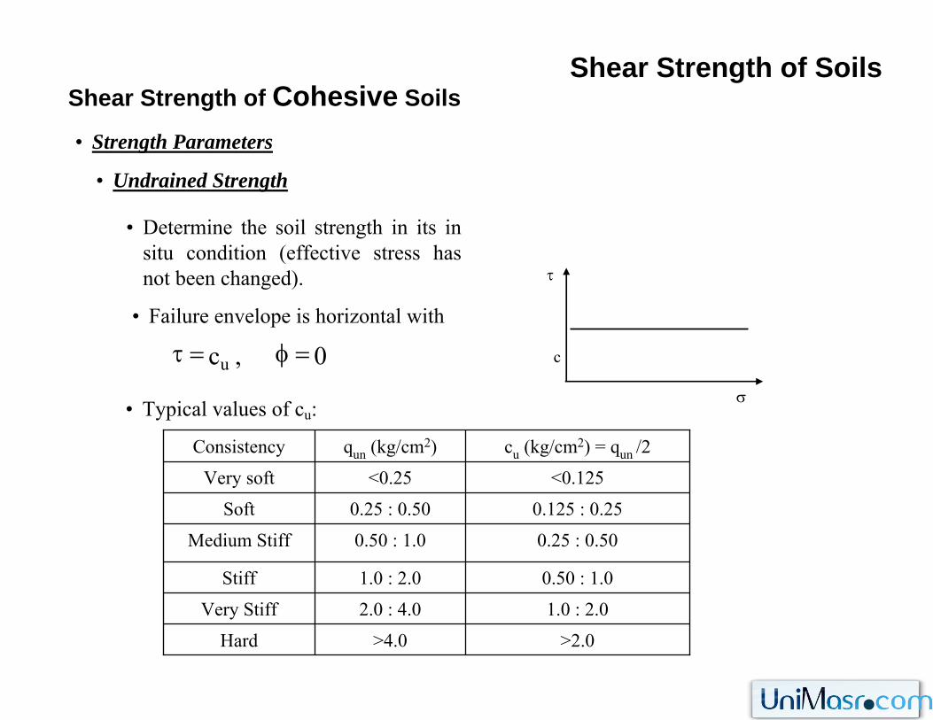
>2.0>4.0Hard
1.0 : 2.02.0 : 4.0Very Stiff
0.50 : 1.01.0 : 2.0Stiff
0.25 : 0.500.50 : 1.0Medium Stiff
0.125 : 0.250.25 : 0.50Soft
<0.125<0.25Very soft
cu (kg/cm2) = qun /2qun (kg/cm2)Consistency
Shear Strength of SoilsShear Strength of Cohesive Soils
• Strength Parameters
• Determine the soil strength in its in situ condition (effective stress has not been changed).
• Typical values of cu:
• Undrained Strength
σ
τ
c
• Failure envelope is horizontal with
0,cu =φ=τ
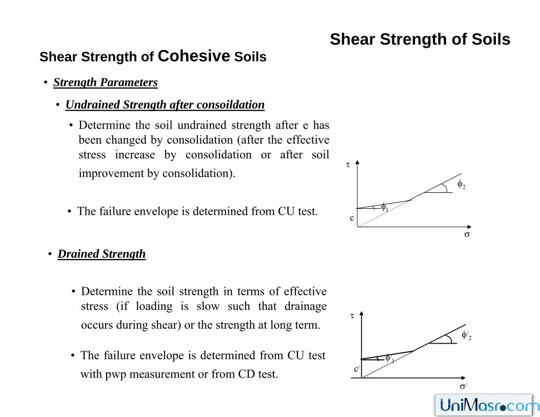
Shear Strength of SoilsShear Strength of Cohesive Soils
• Strength Parameters
• Determine the soil undrained strength after e has been changed by consolidation (after the effective stress increase by consolidation or after soil improvement by consolidation).
• Undrained Strength after consoildation
φ1
σ
τ
φ2
c
• Drained Strength
• Determine the soil strength in terms of effective stress (if loading is slow such that drainage occurs during shear) or the strength at long term.
• The failure envelope is determined from CU test.
• The failure envelope is determined from CU test with pwp measurement or from CD test.
σ/
τ
φ/2
φ/1
c/