Embed Size (px)
Citation preview

Shield Tunnel
Shinji KONISHIJune 23th 2016 Lecture at Waseda Univ.
1

What’s Tunnel?
What’s a tunnel made of ?
Types of Tunnel & Construction Methods
2

Types of Tunnel
Cut & Cover Tunnel
Difference of ground
Shield Tunnel
Mountain Tunnel
Difference of construction method
トンネルの種類
3

大深度地下開発と地下環境 陶野郁雄 鹿島出版会ジオテクノート 東京の地盤 地盤工学会 より
A schematic drawing of geological structure of Tokyo
A diluvium A diluvium
An alluvial
Western part of Tokyo Eastern part of Tokyo
Gravel
4

※成田研究グループ 1962
Ancient Tokyo bay (130,000 years ago)
Diagonal lines : Land
Land Sea
An interglacial period
Sea level rose
5

※遠藤1986
Process of forming the alluvial in Tokyo and environs
25000-20000 years ago (Deep river)
Gravel was piled up.
A glacial epoch
Sea level came down.
6

※遠藤1986
Process of forming the alluvial in Tokyo and environs
10000 years ago (Wide river)
Clay was deposited. Sand was piled up.
Land was encroached by rain
7

※遠藤他1983Diagonal lines : Land
Inner part of Tokyo bay (6,000 years ago)
Land Sea
An interglacial period 8

※遠藤1986
Process of forming the alluvial in Tokyo and environs
6000 years ago (On-lap)
Clay was deposited.
9

※遠藤1986
Process of forming the alluvial in Tokyo and environs
2000 years ago-now (River)
A drowned valley.
10

Ground profile of Tokyo bay costal zone
A drowned valley. A drowned valley.
Western part of Tokyo Eastern part of Tokyo
An alluvial
A diluvium
Very complex ! 11

Contents
1. What’s a shield tunnel?
2. How to make a shield tunnel?
3. Recent record of shield tunnels in Japan.
4. Design method of a shield tunnel.
5. Examples of shield tunnel projects.
6. SENS method
12
Shield Tunnel
新しいシールドトンネルより
1. What’s a shield tunnel?
Cutter face
Skin plate
Shield machine Shield jack
Elector
Segment
13

SegmentStaggered arrangement
Primary liningSecondary lining
Ring joint
Segment joint
Segment
14

Reinforced concrete segment
Ductile cast iron segment
Box type segment Flat type segment
15

Special segments
Honeycomb segmentComposite segment
New Mechanically- jointed Segment
Pin-tenon segment
16

Contents
1. What’s a shield tunnel?
2. How to make a shield tunnel?
3. Recent record of shield tunnels in Japan.
4. Design method of a shield tunnel.
5. Examples of shield tunnel projects.
6. SENS method
17

COMPARISON-1.Outline of construction methods
NATM Shield Cut & cover・Shot Crete, Steel support,Rock Bolt
・Making full use of the natural support function of the surrounding ground
・Prerequisite condition is that face remains standing when excavated
・ Segmental Lining.
・The skin plate of the shield machine, outer backfill layer of the shield and the segmental support the wall of the tunnel.
・Closed-type shield stabilizes the face using earth or slurry to counter earth or hydraulic pressure.
・Earth-retaining wall, Main body
・The ground excavated from the surface to build the tunnel at the desired depth. Then the excavated earth is brought back to restore the surface.
18

NATM Shield Cut & cover・When there is water inflow that affects the self-support of the face or stability of the ground during excavation, water sealing method such as by deep well, well point, or drainage tunnel is necessary.
COMPARISON-2.Countermeasure for underground water
・Usually, closed type shield does not required countermeasures, but the open type does.
・Countermeasures such as deeper penetration of earth retaining wall, groundwater reducing method, soil improvement etc. are usually necessary to overcome boiling or heaving.
Natural water level.
Deep well.
19

Face collapse
20

Open Type Shield
21

(Closed Type Shield)Slurry shield
22

(Closed Type Shield)Earth Pressure Balanced shield
23

Case Study of Railway Shield Tunnel
Open type shield machine(Manual excavation type)
Closed type shield machine(Slurry type)
settlement of the ground: large
In Japan, a shield tunneling method is applied widely in an urban region with soft ground from 1960s.
Open type shieldsettlement of the ground:small
Closed type shield
24

0
40
80
120
160
200
240
~1969
1970~1979
1980~1989
1990~1999
2000~
Num
ber
of s
hiel
d tu
nnne
ls
Selected Shield Type
Applied shield types of each decadeManual excavation Semi-mechanical type
Mechanical typePartial open type
Slurry typeEarth pressure type
ClosedType
After 1980s: Closed type is mainly applied.(1980s: Slurry type, 1990s: Earth pressure type)
1960
s
1970
s
1980
s
1990
s
2000
s
04080
120160200240
Num
ber o
f shi
eld
tunn
els
Before 1970s: Manual excavation type is mainly applied.(Mechanical and Partial open types are also applied.)
25

Simultaneous Back-fill Grouting
Immediate Back-fill Grouting
同時裏込め注入
即時裏込め注入
Fresh grout
Segment
Ground
Tail seal
Void
Hardened grout
26

Tail seal composed of wire brushes and high- viscose grease
Wire brush
ワイヤーブラシ
グリス(充填材) グリス(充填材)
シールド機テール部のスキンプレート
セグメント
Wire brushes
Wire brushes Segment
Skin plate Ground
High-viscose grease 27

Back-fill grouting
1980s: Simultaneous grouting = 25%. 2000s: Simultaneous grouting = Near 80%
Simultaneous grouting increases in number.
0% 20% 40% 60% 80% 100%
1980年代
1990年代
2000年代
Simultaneous grouting
Semi simultaneous groutingImmediate grouting
s
s
s
1980s
1990s
2000s
0% 20% 40% 60% 80% 100%
28

Procedure of shield tunnel construction
2. How to make a shield tunnel?Starting Shaft
Arriving Shaft
Taking a machine apartShield machine
Remove
29

Moving facilitiesClosed Type shield
30

Face(Nanboku Line)(Saitamakousou)
Moving facilities
Like a factory!
Muck Removal Facilities
Elector
31

Facilities
Electric Power Supply Facilities
Lightning System
Inside of a tunnel
Water Supply FacilitiesVentilation Facilities
Material Handling Facilities
Grouting material Supply FacilitiesCommunication Facilities
Grouting material stock FacilitiesMaterial stock Facilities
32

Tunnel entrance
Stock Yard
00:00~6:10
33
12:40~17:2019:14~24:10

Shield tunnel
An example for Railway tunnel Single track tunnel,Kyoto City Subway
An example for Railway tunnel Single track tunnel
An example for Railway tunnel Double track tunnel
34

An example for a sewerage tunnel An example for a water supply tunnel
Typical cross sections of a sewerage tunnel and a water supply tunnel
Segmental lining
Secondary lining
Water pipe
Segmental lining
Secondary lining concrete Inspection gallery
35

Typical cross sections of a power cable tunnel and a telecommunicational tunnel
An example for a power cable tunnel
An example for a telecommunicational tunnel
Segmental lining
Segmental lining
Secondary lining concreteLighting Lighting
RackPowercable
Water cooling pipe
Telecommunication cable
36

An example of Kansai electric company
Telecommunication cable
Powercable
Water cooling pipe
Gas pipe
Water pipe
Typical cross sections of a multiple use tunnel
37

An outline of NTT telecommunicational tunnel
ケーブル
筋金物
受金物
Rectangular tunnelCircular tunnel
Cable
38

LiningSegmental liningPrimary lining
Secondary lining
Steel Segment
Main girder
Longitudinal rib
Skin plate
Splice plate
39

Typical cross sections of a gas pipe tunnel and a road tunnel
An example for a gas pipe tunnel An example for a road tunnel
Segmental lining
Segmental lining Mortar filling
Gas pipe
Secondary lining concrete
Waterproof seat
Ceiling boar bracket
Dust collector installation space
PC ceiling board
Inspection gallery
Circular waterway
Center ditch
The Trans-Tokyo Bay HighwayA four‐lane roadGas-pipe
40
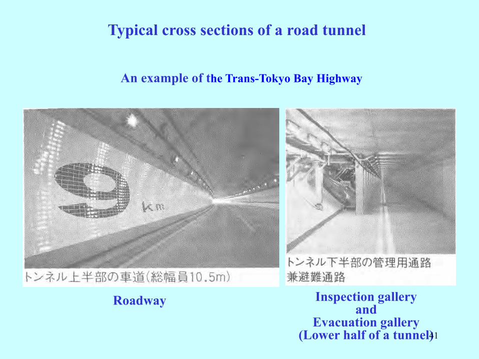
Typical cross sections of a road tunnel
An example of the Trans-Tokyo Bay Highway
Inspection galleryand
Evacuation gallery(Lower half of a tunnel)
Roadway
41

Examples of multiple use shield tunnels
A power cable tunnel
A water supply tunnel
Water pipes
Power cables
42

Conceptual view of a traffic tunnel anda station of the Saitama rapid railway
Water transmission pipe in the invert
43

「導水管」設置状況Setting situation of water transmission pipes
44

Water transmission pipe under a station during construction
45

Winding Shield
46

Electric Power Tunnel
with Sharp Radius, Steep Grade in Large Depth
47

Contents
1. What’s a shield tunnel?
2. How to make a shield tunnel?
3. Recent record of shield tunnels in Japan.
4. Design method of a shield tunnel.
5. Examples of shield tunnel projects.
6. SENS method
48

Achievement of a large face excavation and large overburden excavation
Dep
th(m
)3. Recent record of shield tunnels in Japan.
49

160 120 80 40 0
Electricity
Electricit
yElectricity
Sewer
Electricity
80m 0.54MPa
50m
Sewer
Sewer
30m0.50MPa
20m
0.49MPa
35m
0.56MPa
50m 0.60MPa
90m 0.52MPa
Achievements of a sharp curve execution under high water pressureGround water pressure (MPa)
Minimum curve radius (m)
0.4
0.5
0.6
0.7
0.8
120m 0.60MPa
Sewer
0.72MPa
50

共同溝
電力
電力
共同溝
ガス
ガス
鉄道
下水
電力
電力
下水
ガス(電力)
0
10
20
30
40
50
60
70
2,000 4,000 6,000 8,000 10,000
掘進延長(m)
深度(m)
Achievements of a long distance excavation
Length of excavation (m)
Gas
Gas
Sewer
Railway
Dep
th Electricity
Electricity
Electricity
Electricity
(For electricity)
Gas
Sewer
Multiple use
Multiple use
51

A tunnel for gas conduit connected east area to west area.
52

東西連係ガス導管トンネル
A tunnel for gas conduit connected east area to west area.
Ougijima Shaft Futtsu Shaft
19km
Underground connecting
Underground connecting
9000m9000m
Ougijima Shaft Futtsu Shaft
53

Contents
1. What’s a shield tunnel?
2. How to make a shield tunnel?
3. Recent record of shield tunnels in Japan.
4. Design method of a shield tunnel.
5. Examples of shield tunnel projects.
6. SENS method
54

Ground reaction
45°
45°
q1
R0
Re
Rt
Water pressure Pwl
Earth pressure Pel
Pr=( Pwl+ Pwel)
Surcharge P0
Hw
H
Ground reaction
Ground reaction by vertical load
Wate
r p
ress
ure
Eart
h p
ress
ure
Wate
r p
ress
ure
Eart
h p
ress
ure
Ground reaction by self weight
qwl qel
qwl qel
qr(=kδ)
Pgl(=πg1)
g1
ζ η
Design method of a segmental lining
Usual Calculation Method
Modified Usual Calculation Method
Solid ring with fully flexural rigidity
Structural model of segmental lining:
Interaction model between ground and tunnel lining:
Ground reaction
55

Pvc
λ Pvc
λ Pvs
WL
GL
HW
+Dc
Dc
PW1=W・HW
PW2=W(HW+Dc)
HW
Radial ground reaction spring
Tangential ground reaction spring
Design method of a segmental lining ( Railway Tunnel)
Structural model of segmental lining:
Interaction model between ground and tunnel lining:
Beam-spring model
Full-circumferential spring model
56

{
Earth pressure distribution(Open type shield)

(Closed type shield)
Results of measurement in a sandy layer(Earth pressure, Water pressure)
Water pressureEarth pressure
Legend

Diluvium Clayey soilDiluvium Sandy soil
Effect of back-fill grouting

When injection pressure
become bigger than plan
pressure, the injection is
stopped.
NormalInjection
method
Low strength
arrangement
Standard
arrangement
Material of
back-fill
100%139%Plan injection
rate
50kPa150kPaPlan injection
pressure
Case2Case1
Plan of back-fill grouting

Earth pressure acting on segment
(Diluvium Clayey Soil)
5 months after tail passing5 days after tail passing
Design earth pressure

Earth pressure acting on segment
(Diluvium Sandy Soil)5 month after tail passing Effective earth pressure
Total earth pressure
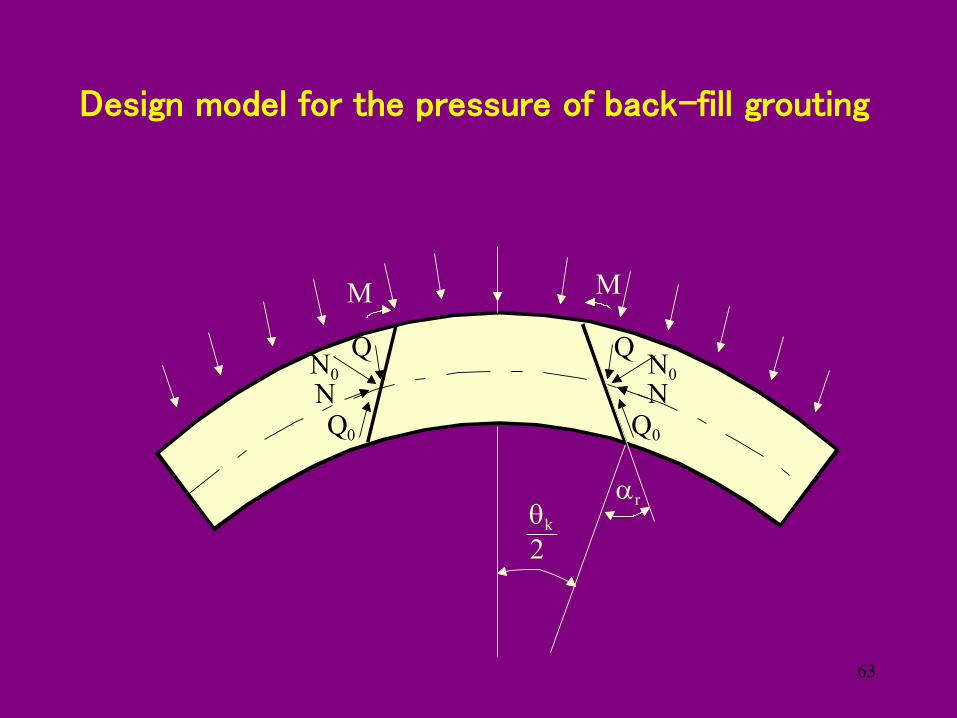
Q
Q0 Q0
QN NN0 N0
k
2
r
M M
Design model for the pressure of back-fill grouting
63

(EA)eq(EI)eq
IA
M
Equivalent rigidity
Coefficient of ground reaction
Jack thrust
Design model for segments in sharp curve
Ground reaction spring
64

Factors causing damage of segment
1) Cracks caused by jack thrust2) Cracks caused by consolidation settlement
around the tunnel3) Cracks caused by the adjacent construction work
to the tunnel
65

Damage due to Construction Load
Crack
SegmentSegment
Crack
Difference
Crack at a corner
Segment
Crack due to a difference(Longitudinal section)
Crack due to a gap
Crack due to a difference(Cross section) Difference
Crack
Chipped at a corner
Ring joints aren’t on a same plane
Crack due to a difference and a gap 66

Crack
Segment
Crack
Jack
SpreaderJackSegment
Tail seal
Crack due to contacts of the shield tail and segments
Crack due to eccentric thrust of a jack
Crack due to a inferior spreader
Crack due to increased friction by hardened tail graut
67

Factors causing damages of segments in the construction procedure
1) Accuracy of assembly of segments2) Control of the attitude of a shield3) Accuracy of manufacture of shield
Countermeasures for prevention of damages of segments
1) The designer of segments should reinforce them by estimating errors on manufacture and construction procedures.
2) The designer should inform the construction foreman of the condition of the design for segments.
68

Contents
1. What’s a shield tunnel?
2. How to make a shield tunnel?
3. Recent record of shield tunnels in Japan.
4. Design method of a shield tunnel.
5. Examples of shield tunnel projects.
6. SENS method
69

An example of a deep tunnel under high underground water pressure
70

Outline of the projectPlan of the project
① 2 mud transport pipes
② Deep・fixed slop
③ With inspection gallery④ Non secondary lining
71

その2工事L=1,500m その3工事L=1,537m その4工事L=1,000m
大船層
小柴層
中里層
Outline of the construction
Total length of the tunnel
Plan view of the tunnel line and ground profile72

レスキュービット
段差ビット
Countermeasure of the long distance excavation
・Different height type bits・Wear detector bits・Rescue bits
Plan
73
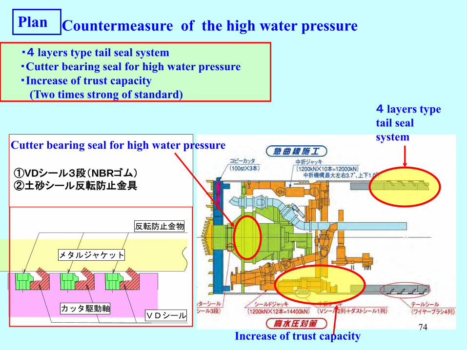
カッタ駆動軸
反転防止金物
VDシール
メタルジャケット
①VDシール3段(NBRゴム)②土砂シール反転防止金具
Countermeasure of the high water pressure・4 layers type tail seal system・Cutter bearing seal for high water pressure・Increase of trust capacity
(Two times strong of standard)
Increase of trust capacity
Cutter bearing seal for high water pressure
4 layers type tail seal system
Plan
74

(1.5MPa)
(0.5MPa)
(1.0MPa)
Muck removal facilities (Slurry shield system)① Gravel crusher measured to high water pressure② Slurry discharge pump measured to high water pressure
Normal crusher
Crusher measured to high water pressure
Slurry discharge pump measured to high water pressure
Plan
75

セグメント、シール材
外径=3,150mm、厚=200mm
Segment, Sealing material
① Non secondary lining: Decrease number of joint boxes, RC plane segment② For long distance excavation: Wedge-pin type joint for workability③ For high water pressure: Sealing material corresponding to 0.9MPa high
water pressure,0.9MPa
Decrease number of joint boxes, RC plane segment
Wedge-pin type joint
Plan
76

切羽水圧の推移
0.00
0.20
0.40
0.60
0.80
1.00
0 200 400 600 800 1000 1200 1400 1600 1800 2000 2200 2400 2600 2800 3000 3200 3400 3600 3800 4000掘進距離(m)
切羽水圧(MPa)
切羽水圧設計
間隙水圧予想
切羽水圧実績
総推力の推移
0
5000
10000
15000
0 200 400 600 800 1000 1200 1400 1600 1800 2000 2200 2400 2600 2800 3000 3200 3400 3600 3800 4000掘進距離(m)総
推力(KN)
総推力装備
総推力予想
総推力実績
推力実績MAX13,000KN
カッタートルクの推移
0100200300400500600700
0 200 400 600 800 1000 1200 1400 1600 1800 2000 2200 2400 2600 2800 3000 3200 3400 3600 3800 4000
掘進距離(m)
カッタートルク(KN-m)
カッタートルク装備
カッタートルク予想
カッタートルク実績
掘進速度の推移
0.0
10.0
20.0
30.0
40.0
50.0
0 200 400 600 800 1000 1200 1400 1600 1800 2000 2200 2400 2600 2800 3000 3200 3400 3600 3800 4000掘進距離(m)
掘進速度(mm/min)
掘進速度計画
掘進速度実績
裏込注入圧の推移
0.000.200.400.600.801.001.201.40
0 200 400 600 800 1000 1200 1400 1600 1800 2000 2200 2400 2600 2800 3000 3200 3400 3600 3800 4000
掘進距離(m)
裏込注入圧(MPa)
切羽水圧実績
裏注圧力実績
間隙水圧予想MAX0.88MPa
裏込注入圧最大1.25MPa(切羽水圧+0.40MPa)
装備トルク 608KN-mα 値=17
推力装備14,400KN
切羽水圧実績MAX0.86MPa
300m
400m2300m
730m
250m
巨礫出現巨礫出現
Thrust force of shield jacksResult
①Slurry pressure at face:Max.0.86MPa, same as results of the advance investigation②Total thrust force:Above the plan, Max.13,000kN(90% of the capacity)Possibility: Appearance of a sandstone, Tightness by fine sand
Change of the total thrust force
Change of the water pressure at the face
Length of advance
Length of advance
Wat
er p
ress
ure
at th
e fa
ceTo
tal t
hrus
t for
ce
77

切羽水圧の推移
0.00
0.20
0.40
0.60
0.80
1.00
0 200 400 600 800 1000 1200 1400 1600 1800 2000 2200 2400 2600 2800 3000 3200 3400 3600 3800 4000掘進距離(m)
切羽水圧(MPa)
切羽水圧設計
間隙水圧予想
切羽水圧実績
総推力の推移
0
5000
10000
15000
0 200 400 600 800 1000 1200 1400 1600 1800 2000 2200 2400 2600 2800 3000 3200 3400 3600 3800 4000掘進距離(m)総
推力(KN)
総推力装備
総推力予想
総推力実績
推力実績MAX13,000KN
カッタートルクの推移
0100200300400500600700
0 200 400 600 800 1000 1200 1400 1600 1800 2000 2200 2400 2600 2800 3000 3200 3400 3600 3800 4000
掘進距離(m)
カッタートルク(KN-m)
カッタートルク装備
カッタートルク予想
カッタートルク実績
掘進速度の推移
0.0
10.0
20.0
30.0
40.0
50.0
0 200 400 600 800 1000 1200 1400 1600 1800 2000 2200 2400 2600 2800 3000 3200 3400 3600 3800 4000掘進距離(m)
掘進速度(mm/min)
掘進速度計画
掘進速度実績
裏込注入圧の推移
0.000.200.400.600.801.001.201.40
0 200 400 600 800 1000 1200 1400 1600 1800 2000 2200 2400 2600 2800 3000 3200 3400 3600 3800 4000
掘進距離(m)
裏込注入圧(MPa)
切羽水圧実績
裏注圧力実績
間隙水圧予想MAX0.88MPa
裏込注入圧最大1.25MPa(切羽水圧+0.40MPa)
装備トルク 608KN-mα 値=17
推力装備14,400KN
切羽水圧実績MAX0.86MPa
300m
400m2300m
730m
250m
巨礫出現巨礫出現
Result Cutter torque
③ Cutter torque:3 times of planned value, Ground characteristic varies widely④Advance speed:limit by the cutter torque
Mudstone:10-20mm/minute, Sandstone: 20-30mm/minute
Change of the cutter torque
Change of the advance speed
Cut
ter
torq
ueA
dvan
ce sp
eed
Length of advance
Length of advance78

砂岩の礫:一軸強度=70~80MPa
泥水漏れ発生(カッターモータハウジングより)
Problems of constructing a deep tunnel under high underground water pressure
Damage of a cutter seal due to high water pressure and large thrust force① Blockade by gravels of sandstone and instantaneous increase of slurry pressure at face② Shortage of capacity of emergency-pressure release device ③ Thrust load acting on a cutter drive unit due to excavation of hard rock
Countermeasure① Replaced with new cutter seals: Over 1 month② Increased the capacity of emergency-pressure
release device, Set sacrifice board③ Set the cutter seal detector unit
Gravels of sandstone Leakage of mud slurry
79

大深度・高水圧施工の課題②
B1
A1 B1
B1
A1 B1
B1
A1 B1
B1
A1 B1
B1
A1 B1
B1
A1 B1
B1
A1 B1
B1
A1 B1
押 板
Cracks due to large thrust force① Bend of shield jacks due to high thrust force
and occurring a horizontal component of a force ② Effect of eccentric thrust loads
Problems of constructing a deep tunnel under high underground water pressure
Countermeasure① Loading points of thrust jacks were modified.② The horizontal component of a force was kept
under control by setting plates for thrust.
Bend of shield jacks and cracks due to thrust forceCracks due to thrust force
80

Continuous Right-angle Excavation Shield MachinesContinuous vertical and cross excavation shield machine
Continuous vertical and cross excavation
Continuous vertical and cross excavation shield machine
81

Vertical Shield Method
>Construction method of a shaft. >Excavate and advance from to ground surface.
Image of construction by vertical shield method Vertical shield machine 82

Clip
Procedure of construction
Set a vertical shield machine in a tunnel
Machining segments at the start point
Completion of assembling a vertical shield machine
83

Completion of assembling
Set a front body Assembling a rear body
Arriving
84
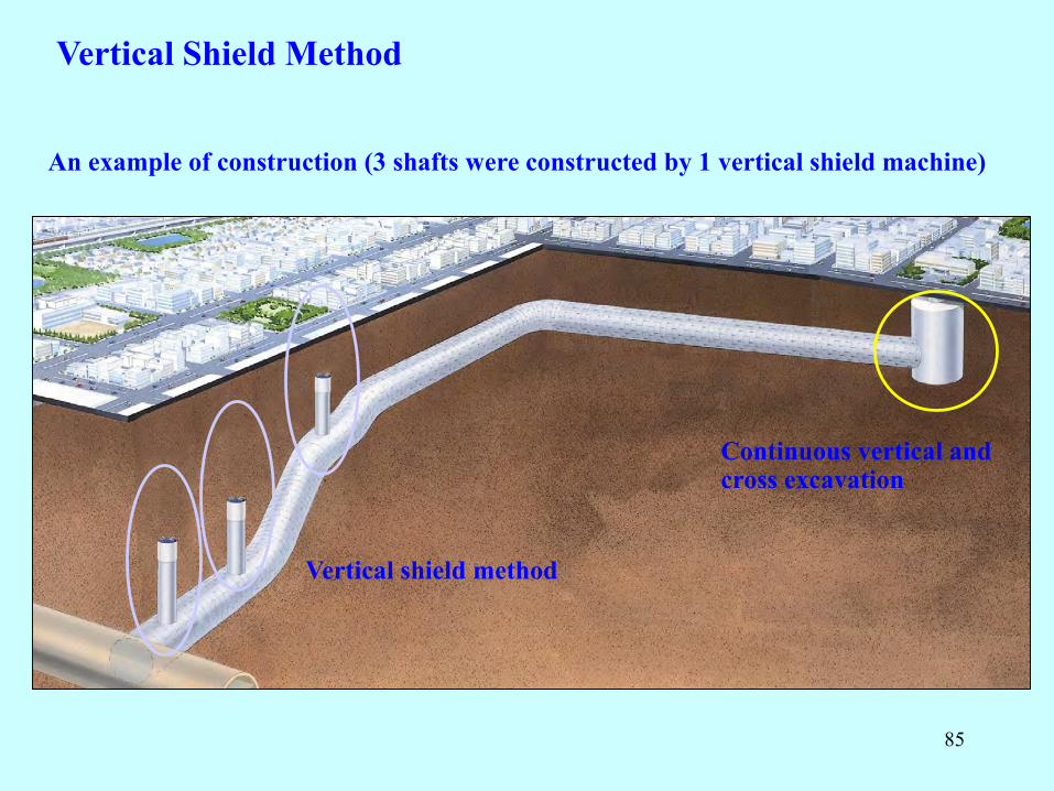
Vertical Shield Method
An example of construction (3 shafts were constructed by 1 vertical shield machine)
Vertical shield method
Continuous vertical and cross excavation
85

Multi circular shield machine ( triple type)
Mother and child shield machine
Specialty shield machines
12:35~17:1619:10~25:40
86

Contents
1. What’s a shield tunnel?
2. How to make a shield tunnel?
3. Recent record of shield tunnels in Japan.
4. Design method of a shield tunnel.
5. Examples of shield tunnel projects.
6. SENS method
87

S: "Shield tunneling method"E: "Extruded concrete lining"N: "NATM"S: "System"
Tunnel: Bored by TBM Primary lining: Cast-in-situ concrete instead of precast segment Secondary lining: Cast-in-situ concrete for finishing
(Cast-in-situ concrete)
Secondary lining
Primary lining
Invert
TBM Inner formfor primary
concrete
(Cast-in-situ concrete)
In SENS method;
New tunnel construction method which is able to improve the safety, economy and workability of the construction.
SENS methodNew construction method "SENS" system
88

11.4
m
Inner formTBM
Screw conveyerInner form assembly equipment
End form
TBM (Muddy soil pressure type)
Primary liningInner form
Facilities of SENS system
89

Sambongihara Tunnel L=4,280mTBM L=3,015m NATM
L=1,265m
Loose sand Clay layer
Excavation by NATM was terminated on Jul., 2004
Remaining 3015m was excavated
by SENS (TBM) method
Tunnel was bored through in Nov, 2006
North portalSouth portal
90

1. Primary lining
2. Invert
Building process
91

3. Waterproof sheet
4. Secondary lining
Building process
92

Average excavating speed Construction cost
0
50
100
150
200
Aver
age
exca
vatin
g sp
eed
(Shield)NATM
(m/m
onth
)
02468
10
Cos
t of c
onst
ruct
ion
for e
ach
exca
vatin
g vo
lum
e (*
1000
0yen
/m3 )
=(*1
00U
SD/m
3 )
(Shield)SENSNATMSENS
Twice faster than NATM Cost of construction for unit excavation volume is almost the same
SENS method is effective in improving the excavating speed.
Comparison between NATM and Shield
93

150
100
50
0Alti
tude
(m)
SENS method
Applied to Tsugaru-Yomogita Tunnel of the Hokkaido Shinkansen Line
Having a good performance in Sambongihara Tunnel
Tsugaru-Yomogita tunnel Tunnel cover is shallow.
Conclusion
6 tunnels were brought together in one tunnel.
Ground is a diluvial loose sandand the ground water level is high.
throughout the tunnel
94

My advice for engineer(on a construction site)
1. Feel strangeness at a glance. >Knowledge, Experience (look at various construction sites.)
3. Simple is the best.
2. Think ahead. >Predict possible troubles.
>Complexness causes accidents.
>Avoid troubles.>Preparation for taking countermeasures to the troubles.
4.Time is money. >Decide quickly how to cope with a trouble when it happen.>Buy time. >After that, modified the countermeasure with observing the situation.
(If the possibility that a countermeasure will succeed is over 50%, you have to go ahead.)
5.Imagination is very important. >Image what’s happen and how does it happen in the blind spaces.95