Embed Size (px)
Citation preview
Indian Institute of Information Technology - Allahabad
Signal Flow Graph
Chapter 4: Nise, N. S. Control System Engineering
Indian Institute of Information Technology - Allahabad
Indian Institute of Information Technology - Allahabad
Indian Institute of Information Technology - Allahabad
Indian Institute of Information Technology - Allahabad
OutlinesBasic Elements of Signal Flow Graph
Basic Properties
Definitions of Signal Flow Graph Terms
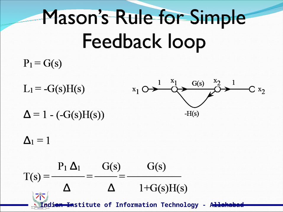
Mason Theory
Examples
SE201 Al-Amer_Term 071 4
Indian Institute of Information Technology - Allahabad
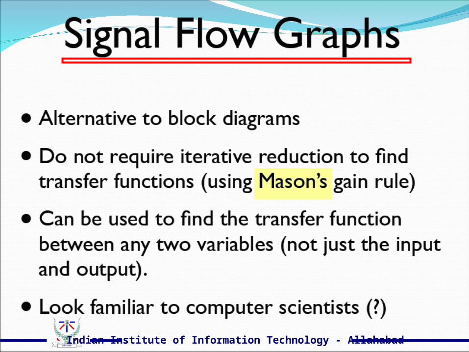
Signal-flow graphFrom Wikipedia, the free encyclopedia
A signal-flow graph (SFG) is a special type of block diagram, constrained by rigid mathematical rules, that is a graphical means of showing the relations among the variables of a set of linear algebraic relations. Nodes represent variables, and are joined by branches that have assigned directions (indicated by arrows) and gains. A signal can transmit only in the direction of the arrow.
Indian Institute of Information Technology - Allahabad
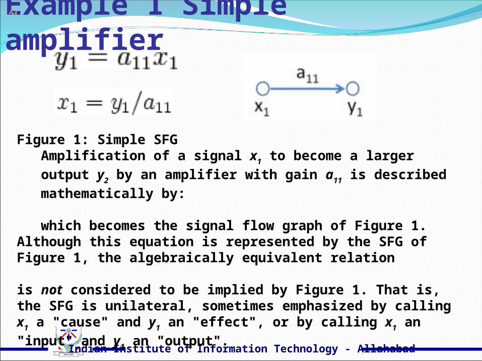
Example 1 Simple amplifier
Figure 1: Simple SFG
Amplification of a signal x1 to become a larger output y2 by an
amplifier with gain a11 is described mathematically by:
which becomes the signal flow graph of Figure 1.
Although this equation is represented by the SFG of Figure 1, the algebraically equivalent relation
is not considered to be implied by Figure 1. That is, the SFG is unilateral, sometimes emphasized by calling x1 a "cause" and y1 an
"effect", or by calling x1 an "input" and y1 an "output".
Indian Institute of Information Technology - Allahabad
Basic Elements of Signal Flow Graph
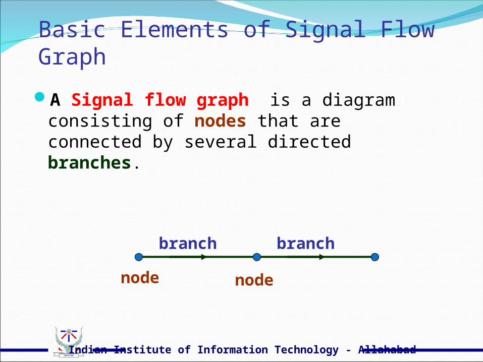
A Signal flow graph is a diagram consisting of nodes that are connected by several directed branches.
node node
branch branch

Indian Institute of Information Technology - Allahabad
Basic Elements of Signal Flow Graph
A node is used to represent a variable (inputs, outputs, other signals)
A branch shows the dependence of one variable ( node) on another variable (node)Each branch has GAIN and DIRECTIONA signal can transmit through a branch only in
the direction of the arrowIf gain is not specified gain =1
A B
G B = G A

Indian Institute of Information Technology - Allahabad
Example 2 Two-port network
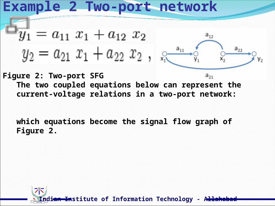
Figure 2: Two-port SFG
The two coupled equations below can represent the current-voltage relations in a two-port network:
which equations become the signal flow graph of Figure 2.

Indian Institute of Information Technology - Allahabad
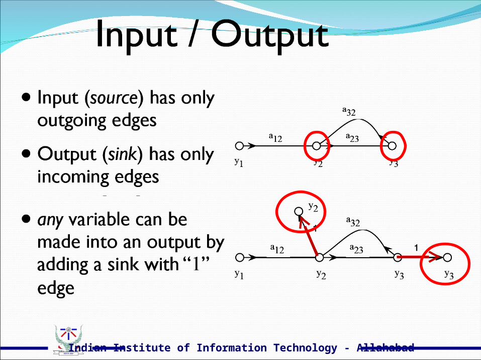
Nodes A node is used to represent a variable Source node (input node)
All braches connected to the node are leaving the node Input signal is not affected by other signals
Sink node (output node) All braches connected to the node are entering the node output signal is not affecting other signals
A B
V U
C
X Y Z
D Source node
Sink node
Indian Institute of Information Technology - Allahabad
Indian Institute of Information Technology - Allahabad
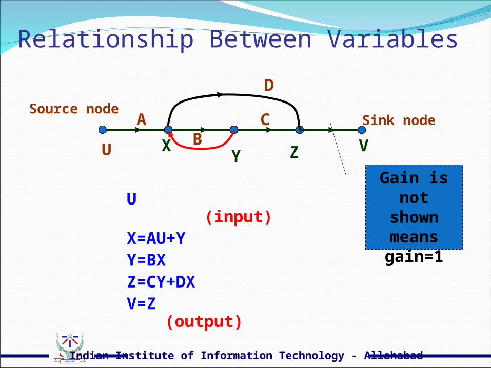
Relationship Between Variables
U (input)X=AU+YY=BXZ=CY+DXV=Z (output)
A B
V U
C
X Y Z
D Source node
Sink node
Gain is not shown means gain=1
Indian Institute of Information Technology - Allahabad
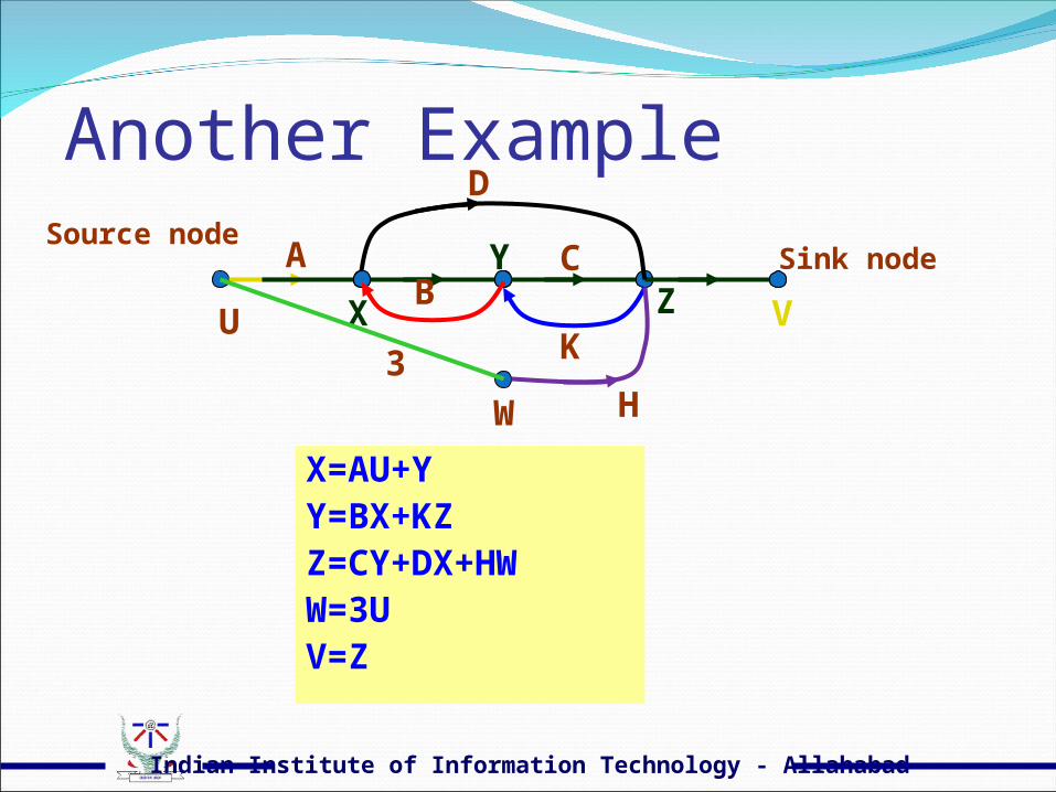
Another Example
X=AU+YY=BX+KZZ=CY+DX+HWW=3UV=Z
A B
V U
C
X
Y Z
D Source node
Sink node
3
W H
K
Indian Institute of Information Technology - Allahabad
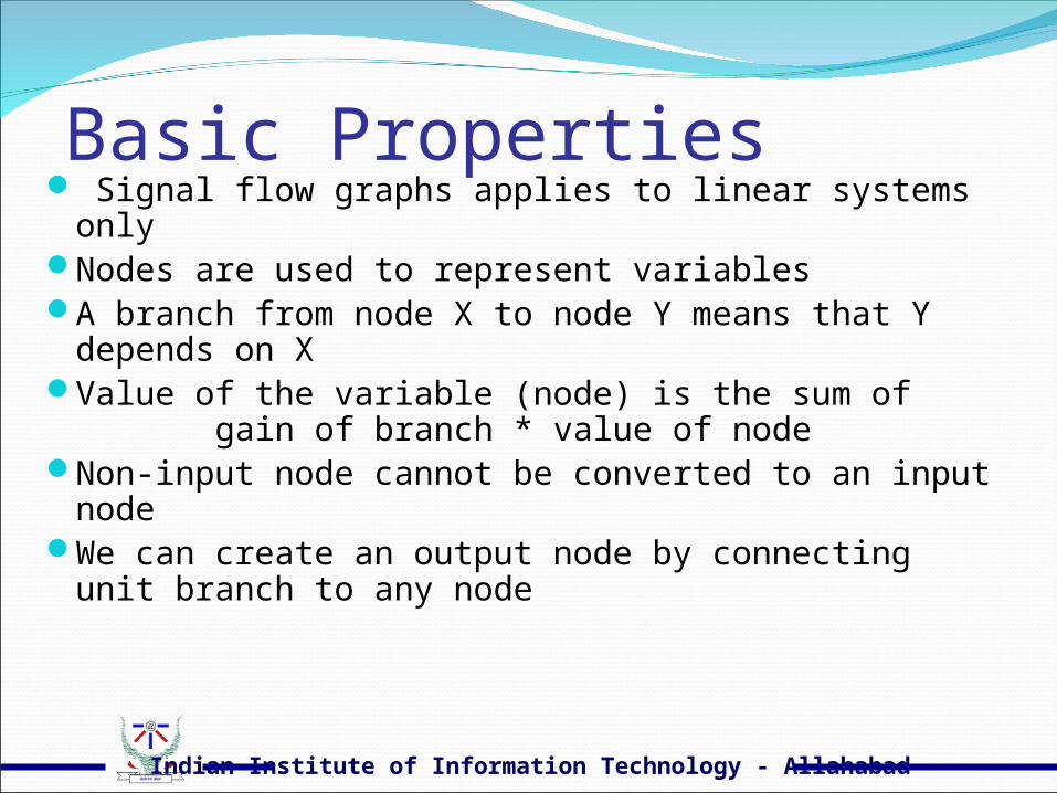
Basic Properties Signal flow graphs applies to linear systems onlyNodes are used to represent variablesA branch from node X to node Y means that Y depends on
XValue of the variable (node) is the sum of gain of
branch * value of nodeNon-input node cannot be converted to an input nodeWe can create an output node by connecting unit branch to
any node
Indian Institute of Information Technology - Allahabad
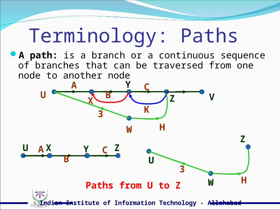
Terminology: PathsA path: is a branch or a continuous sequence of branches
that can be traversed from one node to another node
A B U C X Y Z
A B
V C
X
Y
Z
3
W H
K
U
Z
3
W H Paths from U to Z
U
Indian Institute of Information Technology - Allahabad
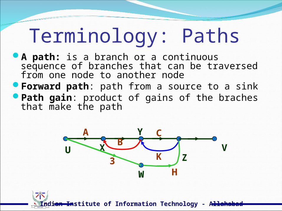
Terminology: PathsA path: is a branch or a continuous sequence of branches
that can be traversed from one node to another nodeForward path: path from a source to a sinkPath gain: product of gains of the braches that make the
path
A B
V U
C
X
Y
Z 3
W H
K
Indian Institute of Information Technology - Allahabad
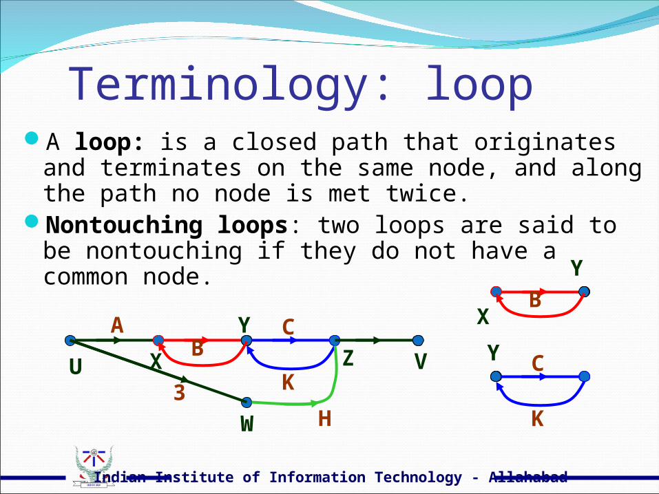
Terminology: loopA loop: is a closed path that originates and terminates
on the same node, and along the path no node is met twice.
Nontouching loops: two loops are said to be nontouching if they do not have a common node.
A B
V U
C
X
Y
Z
3
W H
K C Y
K
B
X
Y
Indian Institute of Information Technology - Allahabad
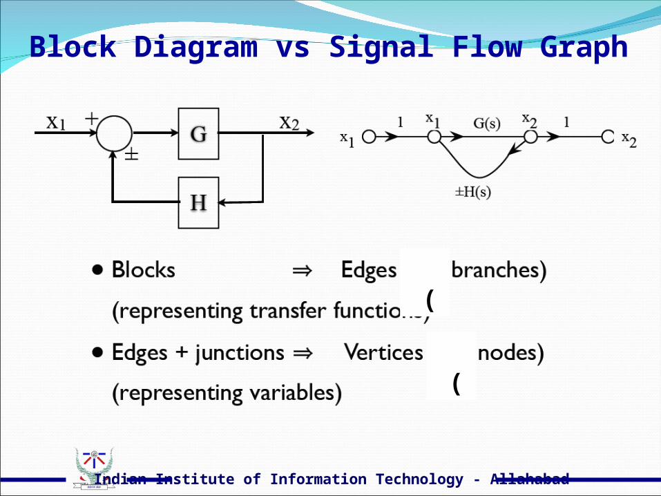
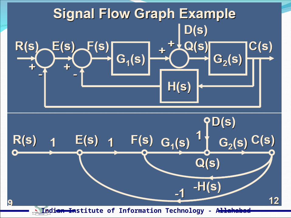
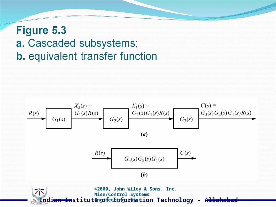
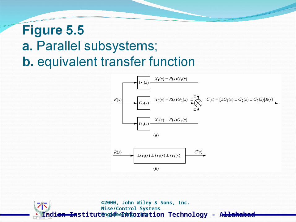
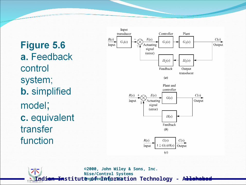
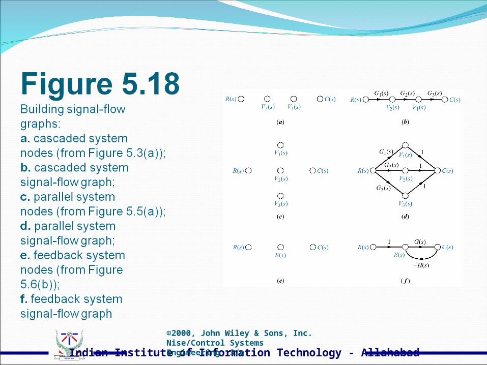
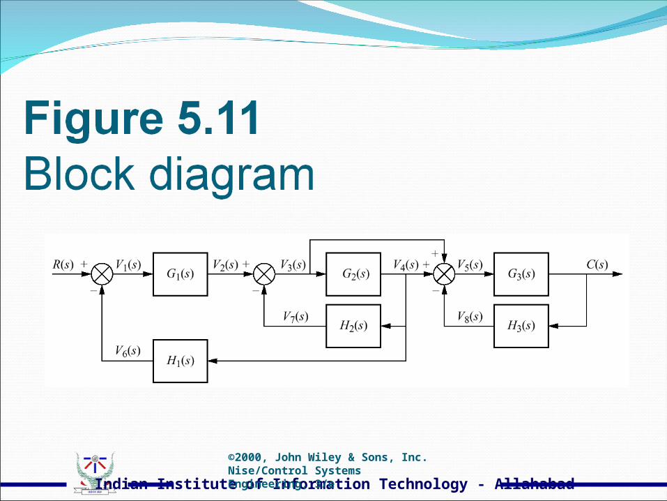
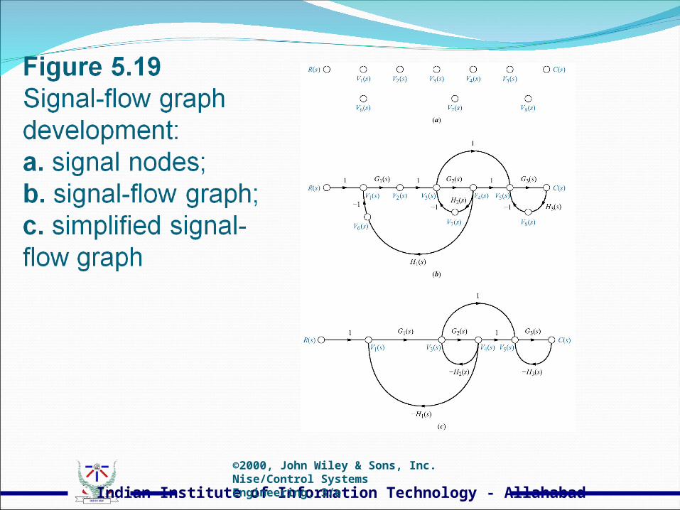
Block Diagram vs Signal Flow Graph
(
(

Indian Institute of Information Technology - Allahabad
Indian Institute of Information Technology - Allahabad
Indian Institute of Information Technology - Allahabad
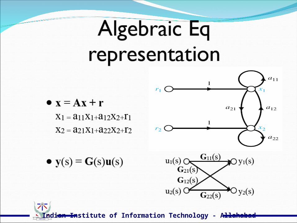
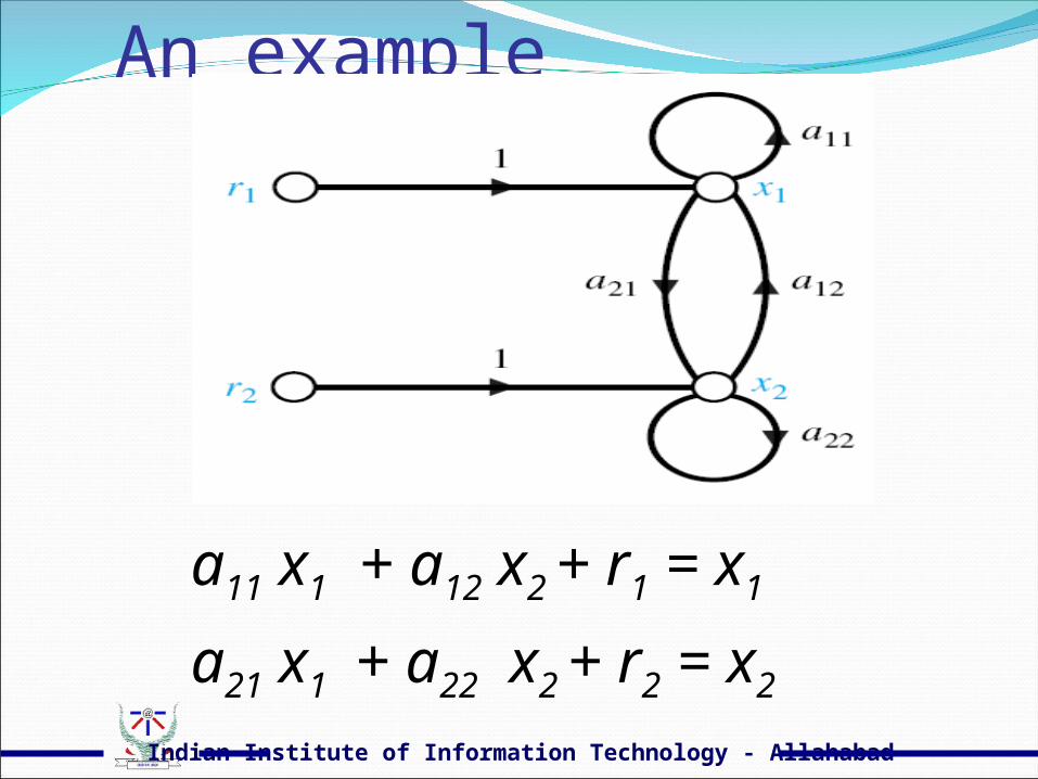
An example
a11 x1 + a12 x2 + r1 = x1
a21 x1 + a22 x2 + r2 = x2
Indian Institute of Information Technology - Allahabad
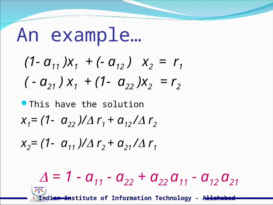
An example… (1- a11 )x1 + (- a12 ) x2 = r1
( - a21 ) x1 + (1- a22 )x2 = r2
This have the solution
x1= (1- a22 )/ r1 + a12 / r2
x2= (1- a11 )/ r2 + a21 / r1
= 1 - a11 - a22 + a22 a11 - a12 a21
Indian Institute of Information Technology - Allahabad
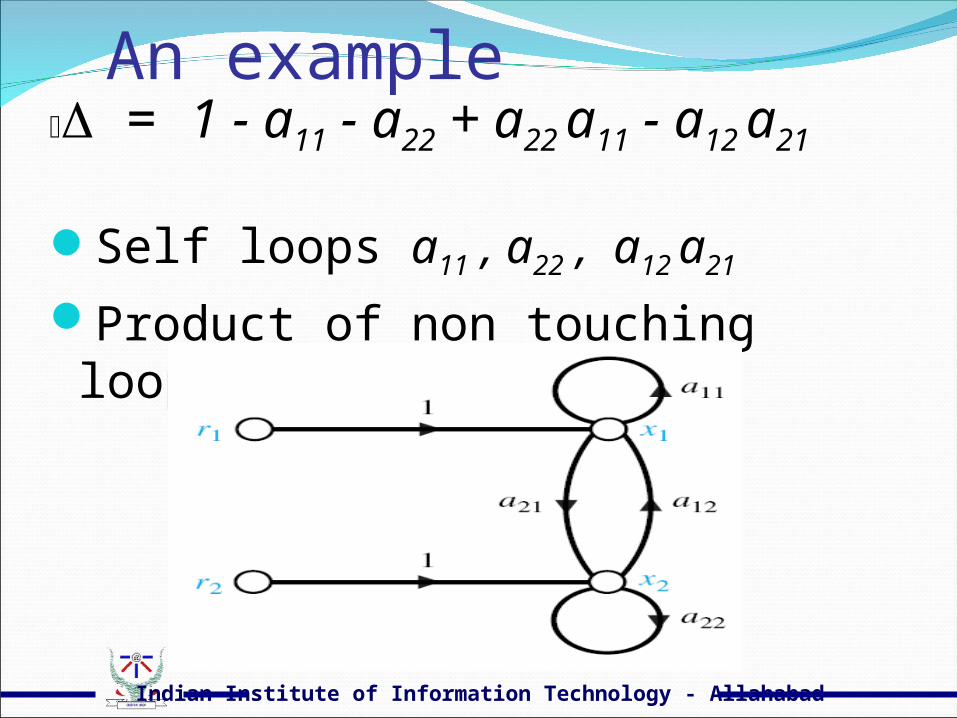
An example = 1 - a11 - a22 + a22 a11 - a12 a21
Self loops a11 , a22 , a12 a21
Product of non touching loops a22 a11
Indian Institute of Information Technology - Allahabad
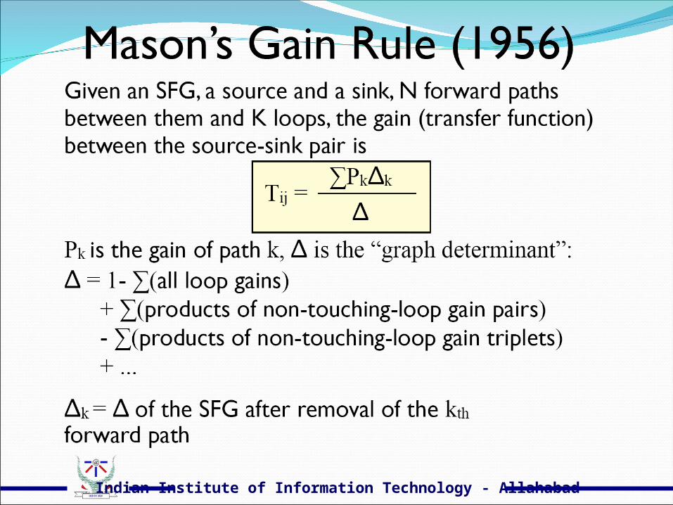
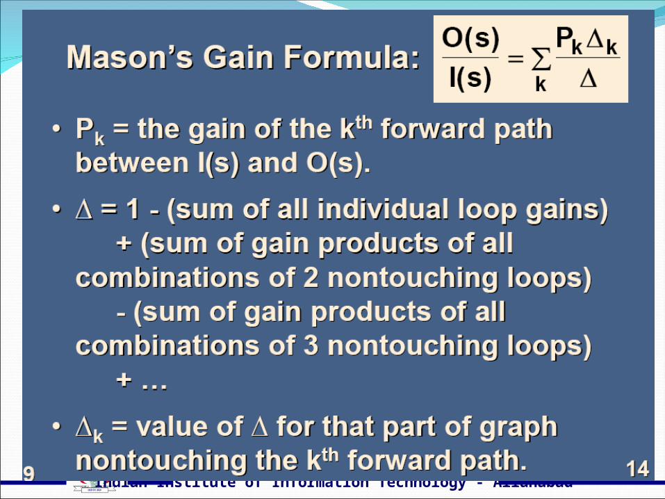
SGF : in general
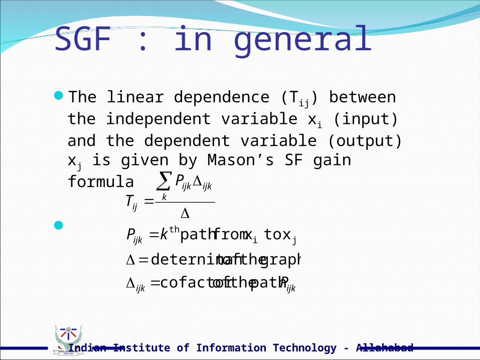
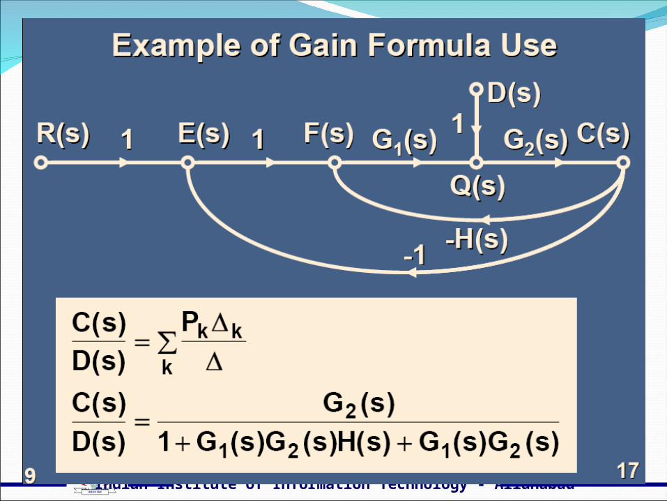
The linear dependence (Tij) between the independent variable xi (input) and the dependent variable (output) xj is given by Mason’s SF gain formula
ijkijk
ijk
kijkijk
ij
P
kP
PT
paththeofcofactor
graphtheoftdeterninan
xtoxfrompath jith
Indian Institute of Information Technology - Allahabad
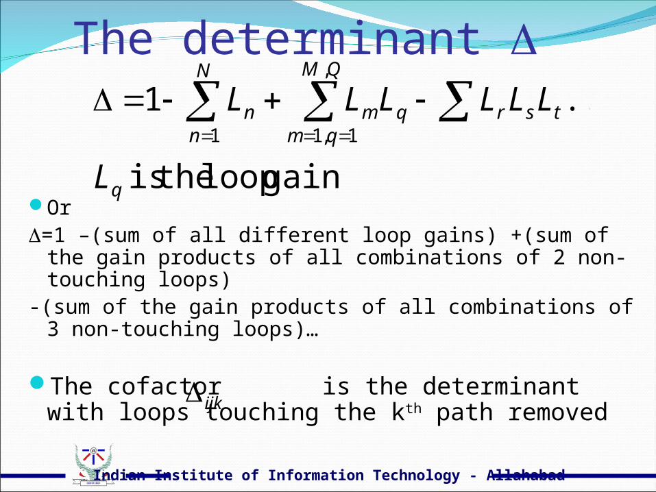
The determinant
Or =1 –(sum of all different loop gains) +(sum of the gain
products of all combinations of 2 non-touching loops)-(sum of the gain products of all combinations of 3 non-
touching loops)…
The cofactor is the determinant with loops touching the kth path removed
gainlooptheis
...11
,
1,1
q
N
n
QM
qmtsrqmn
L
LLLLLL
ijk
Indian Institute of Information Technology - Allahabad

Indian Institute of Information Technology - Allahabad

Indian Institute of Information Technology - Allahabad
Indian Institute of Information Technology - Allahabad
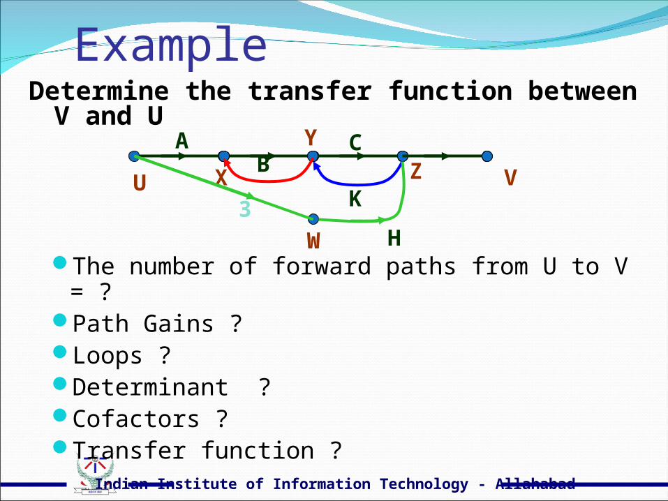
Example
The number of forward paths from U to V = ?Path Gains ?Loops ?Determinant ?Cofactors ?Transfer function ?
A B
V U
C
X
Y
Z
3
W H
K
Determine the transfer function between V and U
Indian Institute of Information Technology - Allahabad
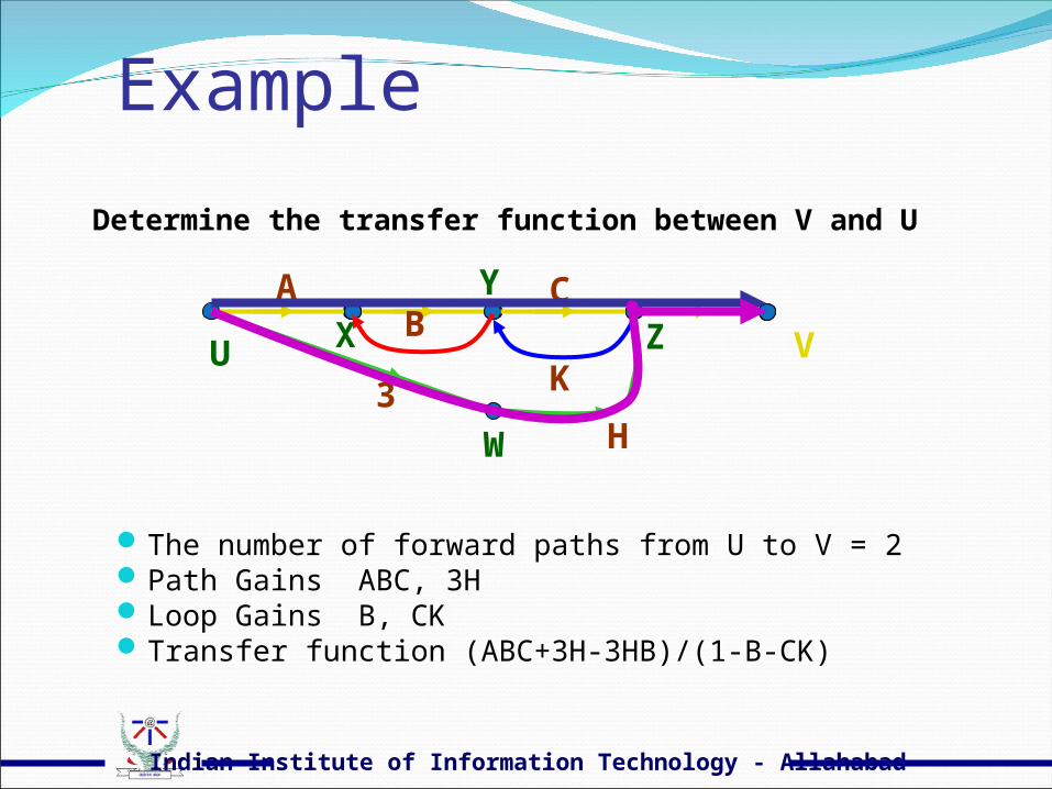
Example
The number of forward paths from U to V = 2Path Gains ABC, 3HLoop Gains B, CKTransfer function (ABC+3H-3HB)/(1-B-CK)
A B
V U
C X
Y
Z
3
W H
K
Determine the transfer function between V and U
Indian Institute of Information Technology - Allahabad
Indian Institute of Information Technology - Allahabad

Indian Institute of Information Technology - Allahabad
Indian Institute of Information Technology - Allahabad
Indian Institute of Information Technology - Allahabad
Indian Institute of Information Technology - Allahabad

Indian Institute of Information Technology - Allahabad
Indian Institute of Information Technology - Allahabad
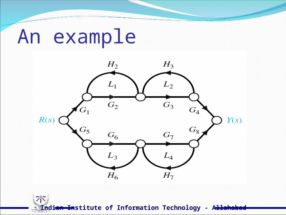
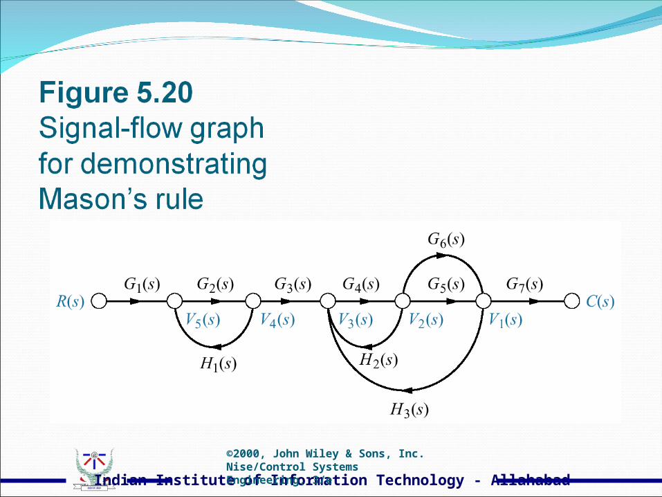
An example
Indian Institute of Information Technology - Allahabad
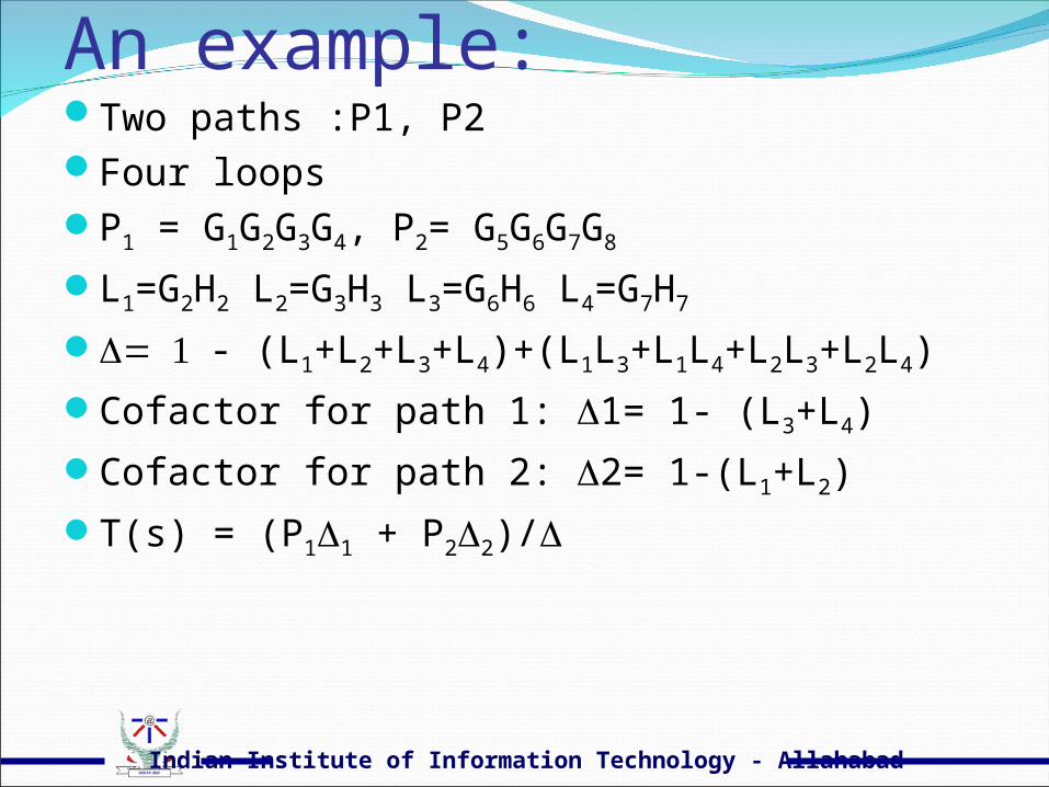
An example:Two paths :P1, P2Four loopsP1 = G1G2G3G4, P2= G5G6G7G8
L1=G2H2 L2=G3H3 L3=G6H6 L4=G7H7
- (L1+L2+L3+L4)+(L1L3+L1L4+L2L3+L2L4)
Cofactor for path 1: 1= 1- (L3+L4)
Cofactor for path 2: 2= 1-(L1+L2)
T(s) = (P11 + P22)/
Indian Institute of Information Technology - Allahabad
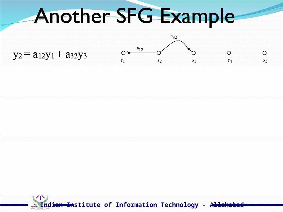
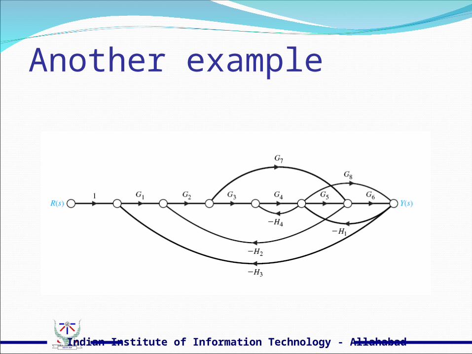
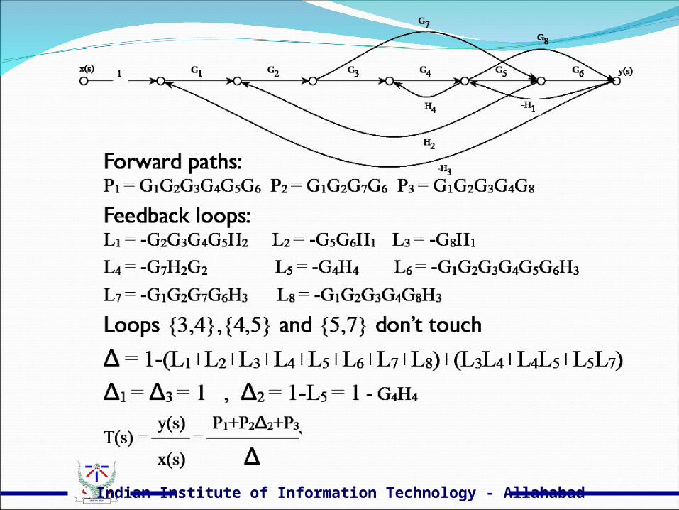
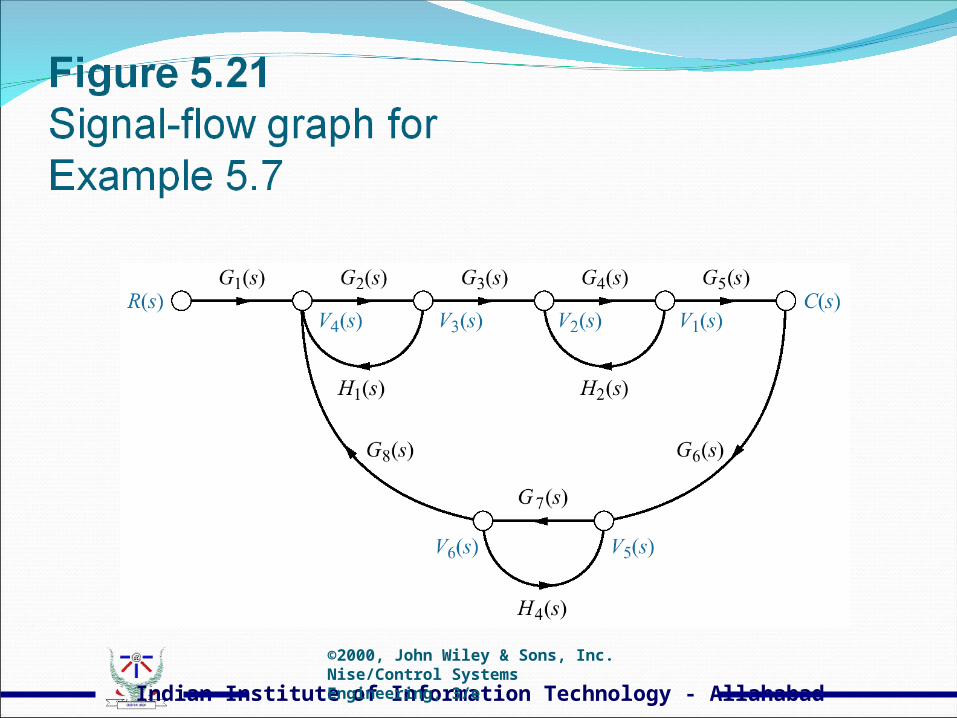
Another example

Indian Institute of Information Technology - Allahabad
3 Paths8 loops
SE201 Al-Amer_Term 071 41
Indian Institute of Information Technology - Allahabad
Indian Institute of Information Technology - Allahabad
Indian Institute of Information Technology - Allahabad
Indian Institute of Information Technology - Allahabad
Indian Institute of Information Technology - Allahabad
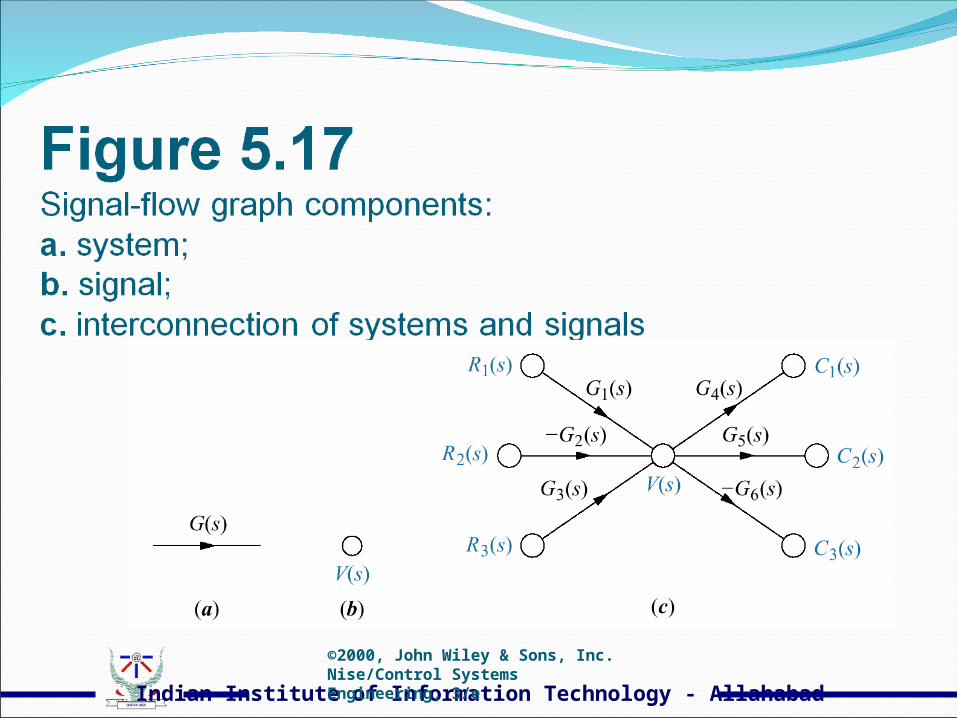
Indian Institute of Information Technology - Allahabad©2000, John Wiley & Sons, Inc.Nise/Control Systems Engineering, 3/e
Indian Institute of Information Technology - Allahabad©2000, John Wiley & Sons, Inc.Nise/Control Systems Engineering, 3/e
Indian Institute of Information Technology - Allahabad©2000, John Wiley & Sons, Inc.Nise/Control Systems Engineering, 3/e
Indian Institute of Information Technology - Allahabad©2000, John Wiley & Sons, Inc.Nise/Control Systems Engineering, 3/e
Indian Institute of Information Technology - Allahabad©2000, John Wiley & Sons, Inc.Nise/Control Systems Engineering, 3/e
Indian Institute of Information Technology - Allahabad©2000, John Wiley & Sons, Inc.Nise/Control Systems Engineering, 3/e
Indian Institute of Information Technology - Allahabad©2000, John Wiley & Sons, Inc.Nise/Control Systems Engineering, 3/e
Indian Institute of Information Technology - Allahabad©2000, John Wiley & Sons, Inc.Nise/Control Systems Engineering, 3/e
Indian Institute of Information Technology - Allahabad©2000, John Wiley & Sons, Inc.Nise/Control Systems Engineering, 3/e
Indian Institute of Information Technology - Allahabad
Example 2 Two-port network
Figure 2: Two-port SFG
The two coupled equations below can represent the current-voltage relations in a two-port network:
which equations become the signal flow graph of Figure 2.

Indian Institute of Information Technology - Allahabad
KeywordsNodeBranchPathLoopNon-touching loopsLoop gainSink nodeSource node
• Forward path
• Co-factor