Embed Size (px)
Citation preview
©Silberschatz, Korth and Sudarshan1.1Database System Concepts
AandachtspuntenAandachtspunten
Deadlines – alles op tijd inleveren!
Lees goed wat van je verwacht wordt!
Planning: de roosters van vergadertrainingen en een anti-RSI training staan op het OGO webpagina.
©Silberschatz, Korth and Sudarshan1.2Database System Concepts
Wat gaan wij leren?Wat gaan wij leren?
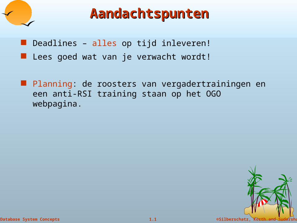
Data Bases
Data modelleren Hoe kan ik zien wat voor informatiesysteem er nodig is?
Hoe maak ik een formeel model van een complex systeem op basis van de tekstuele beschrijving van het systeem?
Hoe vertaal ik het model naar de tabelstructuur van de database?
Queries Hoe maak ik queries aan de database? (d.w.z. hoe vertaal ik de
vraag van het Nederlands naar een query taal)
Hoe lees ik de queries die door andere mensen geschreven zijn? (d.w.z. hoe vertaal ik de query naar het Nederlands)
©Silberschatz, Korth and Sudarshan1.3Database System Concepts
BronnenBronnen
Studiemateriaal : A. Silberschatz, H.F. Korth, S. Sudarshan, "Database System Concepts" (4th Edition), McGraw-Hill, 2002.
PP-presentaties zijn beschikbaar op studyweb
©Silberschatz, Korth and Sudarshan1.4Database System Concepts
Database Management System (DBMS)Database Management System (DBMS)
Collection of interrelated data Set of programs to access the data DBMS contains information about a particular enterprise DBMS provides an environment that is both convenient and
efficient to use. Database Applications:
Banking: all transactions Airlines: reservations, schedules Universities: registration, grades Sales: customers, products, purchases Manufacturing: production, inventory, orders, supply chain Human resources: employee records, salaries, tax deductions
Databases touch all aspects of our lives
©Silberschatz, Korth and Sudarshan1.5Database System Concepts
Instances and SchemasInstances and Schemas
Schema – the logical structure of the database e.g., the database consists of information about a set of customers and
accounts and the relationship between them)
Physical schema: database design at the physical level
Logical schema: database design at the logical level
Instance – the actual content of the database at a particular point in time Analogous to the value of a variable
©Silberschatz, Korth and Sudarshan1.6Database System Concepts
Data ModelsData Models
A collection of tools for describing data data relationships data semantics data constraints
Entity-Relationship model
Relational model
Other models: object-oriented model semi-structured data models Older models: network model and hierarchical model
©Silberschatz, Korth and Sudarshan1.7Database System Concepts
Entity-Relationship ModelEntity-Relationship Model
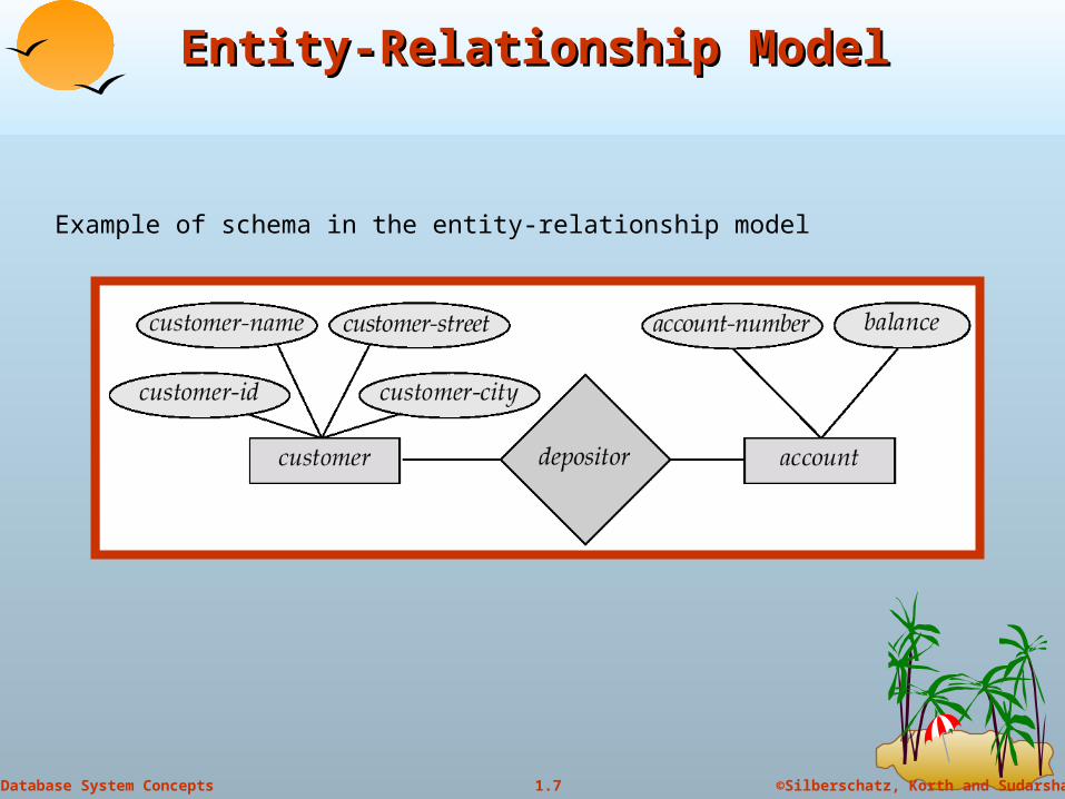
Example of schema in the entity-relationship model
©Silberschatz, Korth and Sudarshan1.8Database System Concepts
Entity Relationship Model (Cont.)Entity Relationship Model (Cont.)
E-R model of real world Entities (objects)
E.g. customers, accounts, bank branch
Relationships between entities
E.g. Account A-101 is held by customer Johnson
Relationship set depositor associates customers with accounts
Widely used for database design Database design in E-R model usually converted to design in the
relational model (coming up next) which is used for storage and processing
©Silberschatz, Korth and Sudarshan1.9Database System Concepts
Relational ModelRelational Model
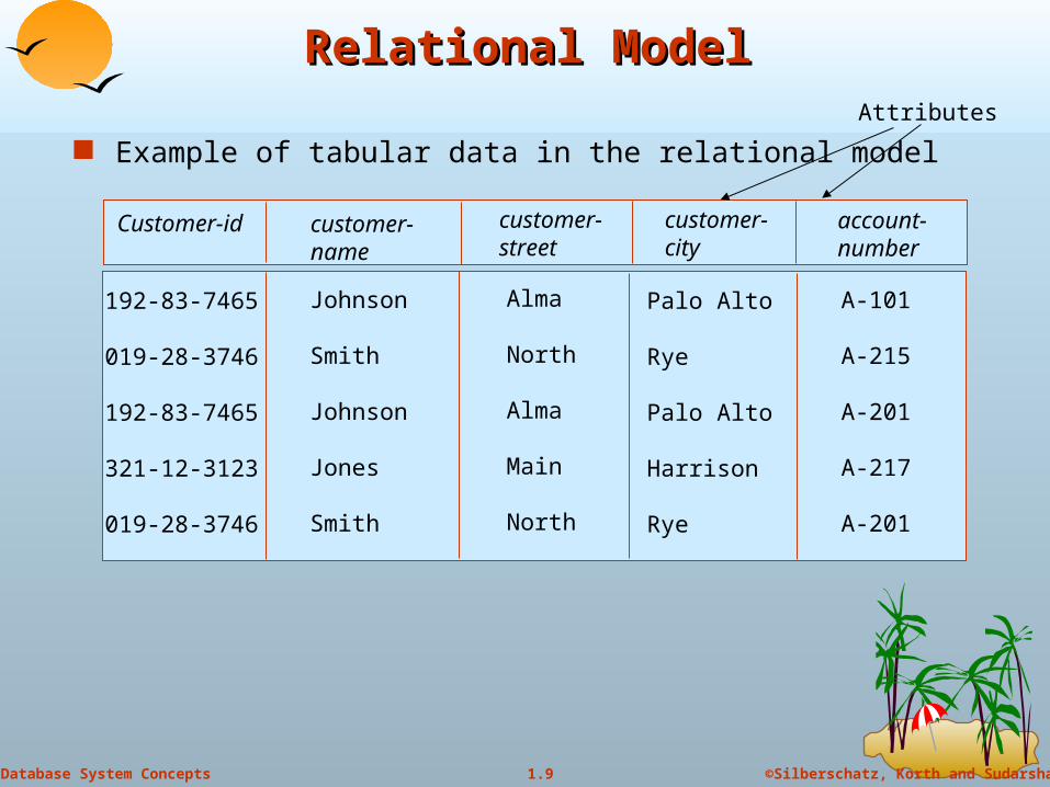
Example of tabular data in the relational model
customer-name
Customer-id customer-street
customer-city
account-number
Johnson
Smith
Johnson
Jones
Smith
192-83-7465
019-28-3746
192-83-7465
321-12-3123
019-28-3746
Alma
North
Alma
Main
North
Palo Alto
Rye
Palo Alto
Harrison
Rye
A-101
A-215
A-201
A-217
A-201
Attributes
©Silberschatz, Korth and Sudarshan1.10Database System Concepts
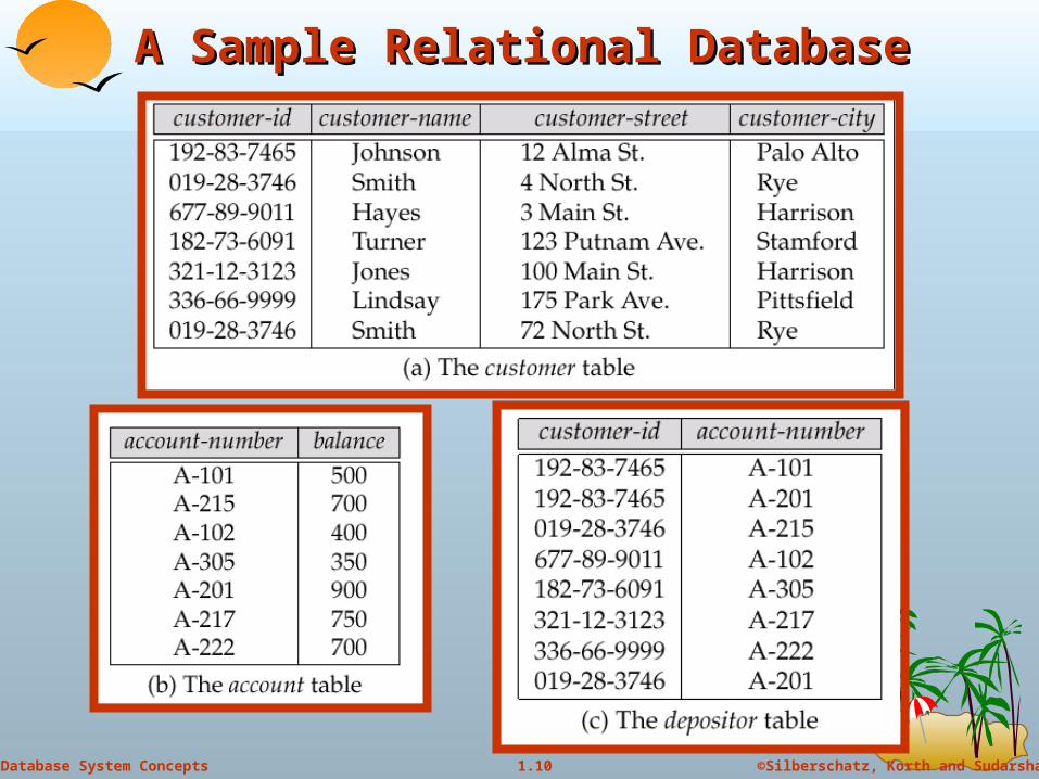
A Sample Relational DatabaseA Sample Relational Database
©Silberschatz, Korth and Sudarshan1.11Database System Concepts
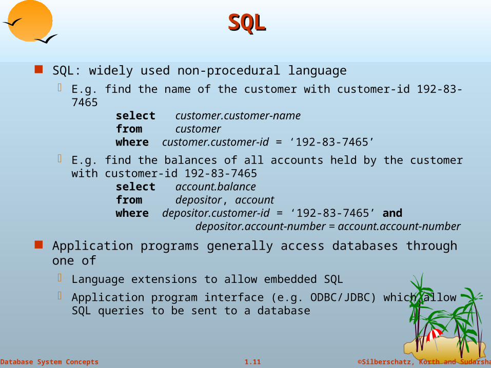
SQLSQL
SQL: widely used non-procedural language E.g. find the name of the customer with customer-id 192-83-7465
select customer.customer-namefrom customerwhere customer.customer-id = ‘192-83-7465’
E.g. find the balances of all accounts held by the customer with customer-id 192-83-7465
select account.balancefrom depositor, accountwhere depositor.customer-id = ‘192-83-7465’ and depositor.account-number = account.account-
number
Application programs generally access databases through one of Language extensions to allow embedded SQL
Application program interface (e.g. ODBC/JDBC) which allow SQL queries to be sent to a database

©Silberschatz, Korth and Sudarshan1.12Database System Concepts
Entity-Relationship ModelEntity-Relationship Model
Entity Sets
Relationship Sets
Design Issues
Mapping Constraints
Keys
E-R Diagram
Extended E-R Features
Design of an E-R Database Schema
Reduction of an E-R Schema to Tables
©Silberschatz, Korth and Sudarshan1.13Database System Concepts
Entity SetsEntity Sets
A database can be modeled as: a collection of entities,
relationship among entities.
An entity is an object that exists and is distinguishable from other objects.
Example: specific person, company, event, plant
Entities have attributes Example: people have names and addresses
An entity set is a set of entities of the same type that share the same properties. Example: set of all persons, companies, trees, holidays
©Silberschatz, Korth and Sudarshan1.14Database System Concepts
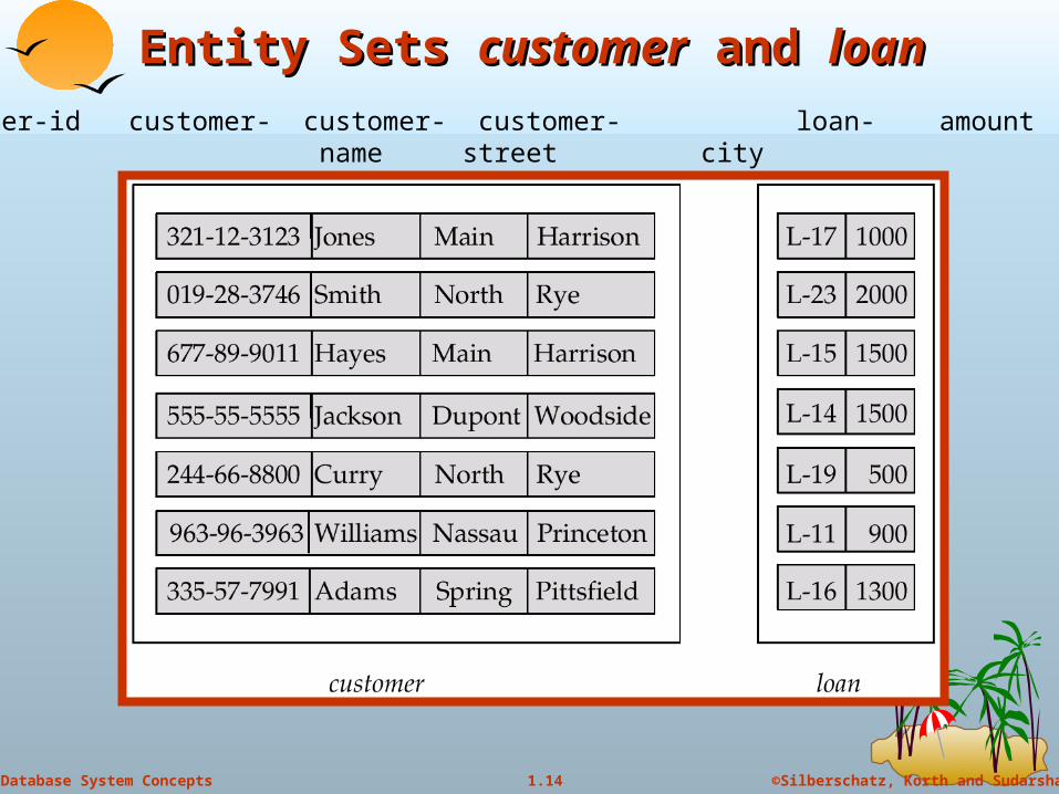
Entity Sets Entity Sets customercustomer and and loanloan
customer-id customer- customer- customer- loan- amount name street city number
©Silberschatz, Korth and Sudarshan1.15Database System Concepts
AttributesAttributes
An entity is represented by a set of attributes, that is descriptive properties possessed by all members of an entity set.
Domain – the set of permitted values for each attribute
Example:
customer = (customer-id, customer-name, customer-street, customer-city)
loan = (loan-number, amount)
©Silberschatz, Korth and Sudarshan1.16Database System Concepts
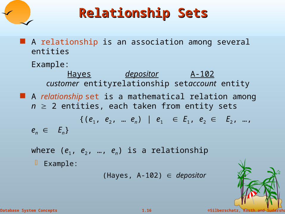
Relationship SetsRelationship Sets
A relationship is an association among several entities
Example:Hayes depositor A-102
customer entity relationship set account entity
A relationship set is a mathematical relation among n 2 entities, each taken from entity sets
{(e1, e2, … en) | e1 E1, e2 E2, …, en En}
where (e1, e2, …, en) is a relationship
Example:
(Hayes, A-102) depositor
©Silberschatz, Korth and Sudarshan1.17Database System Concepts
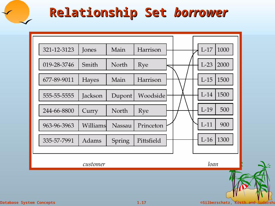
Relationship Set Relationship Set borrowerborrower
©Silberschatz, Korth and Sudarshan1.18Database System Concepts
Degree of a Relationship SetDegree of a Relationship Set
Refers to number of entity sets that participate in a relationship set.
Relationship sets that involve two entity sets are binary (or degree two). Generally, most relationship sets in a database system are binary.
Binary relationship set can be of one of the following types: One to one
One to many
Many to one
Many to many
©Silberschatz, Korth and Sudarshan1.19Database System Concepts
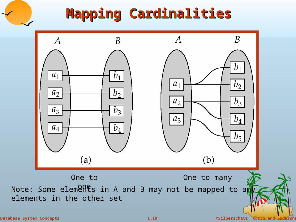
Mapping CardinalitiesMapping Cardinalities
One to one One to many
Note: Some elements in A and B may not be mapped to any elements in the other set
©Silberschatz, Korth and Sudarshan1.20Database System Concepts
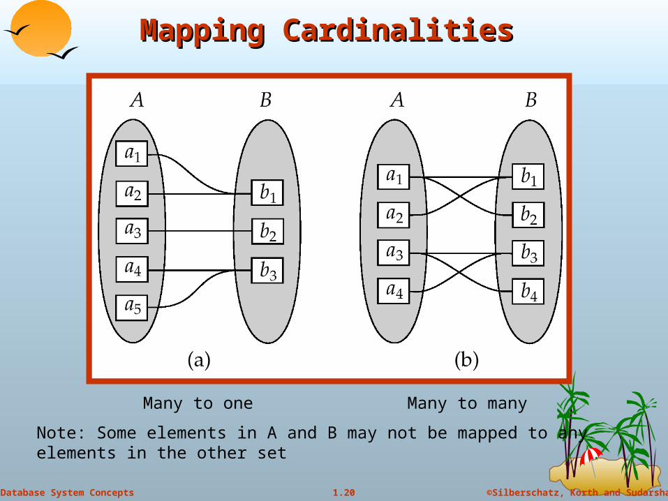
Mapping Cardinalities Mapping Cardinalities
Many to one Many to many
Note: Some elements in A and B may not be mapped to any elements in the other set
©Silberschatz, Korth and Sudarshan1.21Database System Concepts
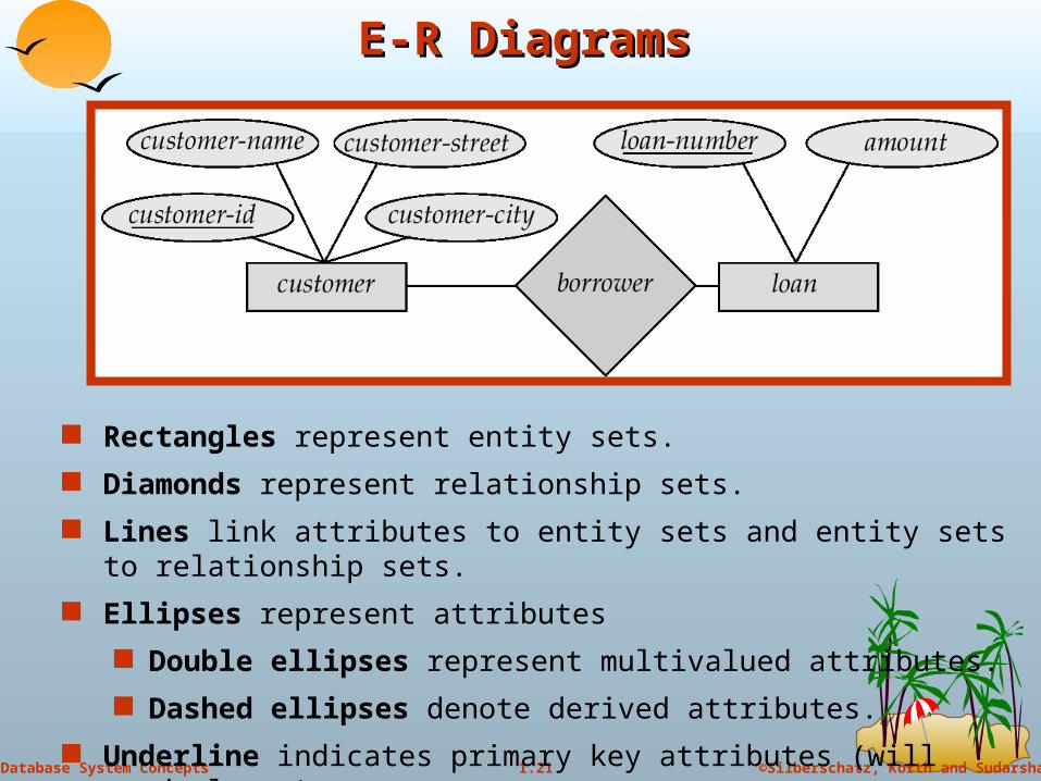
E-R DiagramsE-R Diagrams
Rectangles represent entity sets.
Diamonds represent relationship sets.
Lines link attributes to entity sets and entity sets to relationship sets.
Ellipses represent attributes
Double ellipses represent multivalued attributes.
Dashed ellipses denote derived attributes.
Underline indicates primary key attributes (will study later)
©Silberschatz, Korth and Sudarshan1.22Database System Concepts
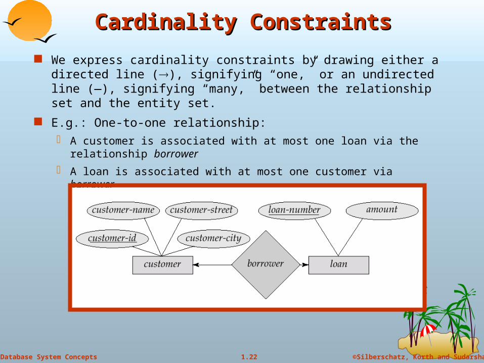
Cardinality ConstraintsCardinality Constraints
We express cardinality constraints by drawing either a directed line (), signifying “one,” or an undirected line (—), signifying “many,” between the relationship set and the entity set.
E.g.: One-to-one relationship: A customer is associated with at most one loan via the relationship
borrower
A loan is associated with at most one customer via borrower
©Silberschatz, Korth and Sudarshan1.23Database System Concepts
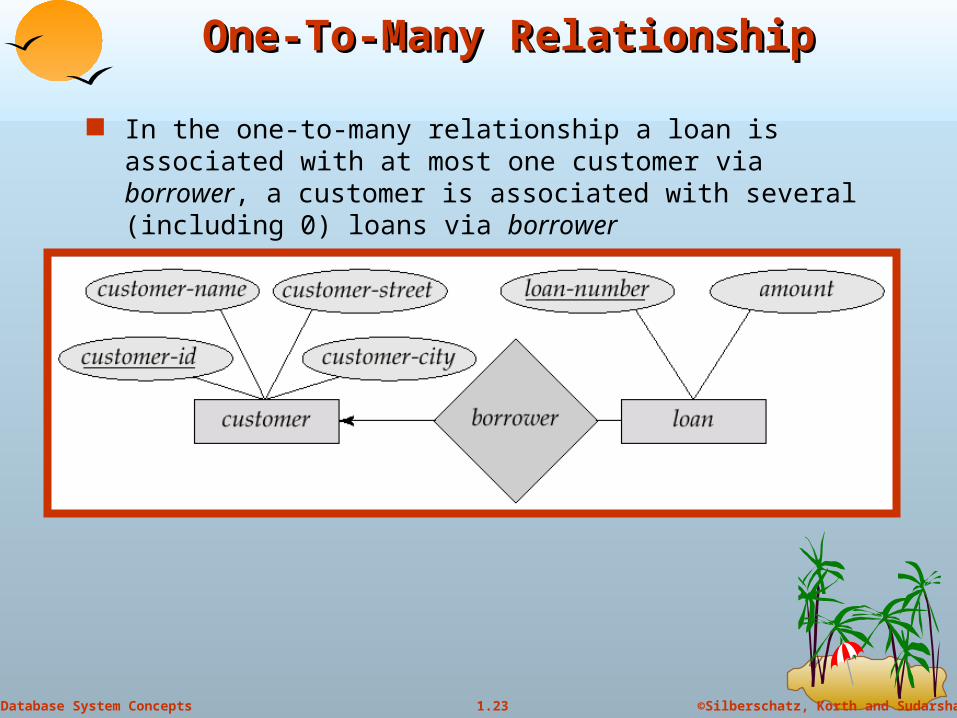
One-To-Many RelationshipOne-To-Many Relationship
In the one-to-many relationship a loan is associated with at most one customer via borrower, a customer is associated with several (including 0) loans via borrower
©Silberschatz, Korth and Sudarshan1.24Database System Concepts
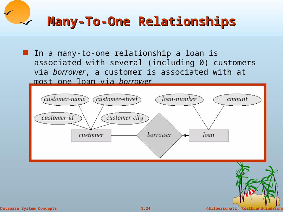
Many-To-One RelationshipsMany-To-One Relationships
In a many-to-one relationship a loan is associated with several (including 0) customers via borrower, a customer is associated with at most one loan via borrower
©Silberschatz, Korth and Sudarshan1.25Database System Concepts
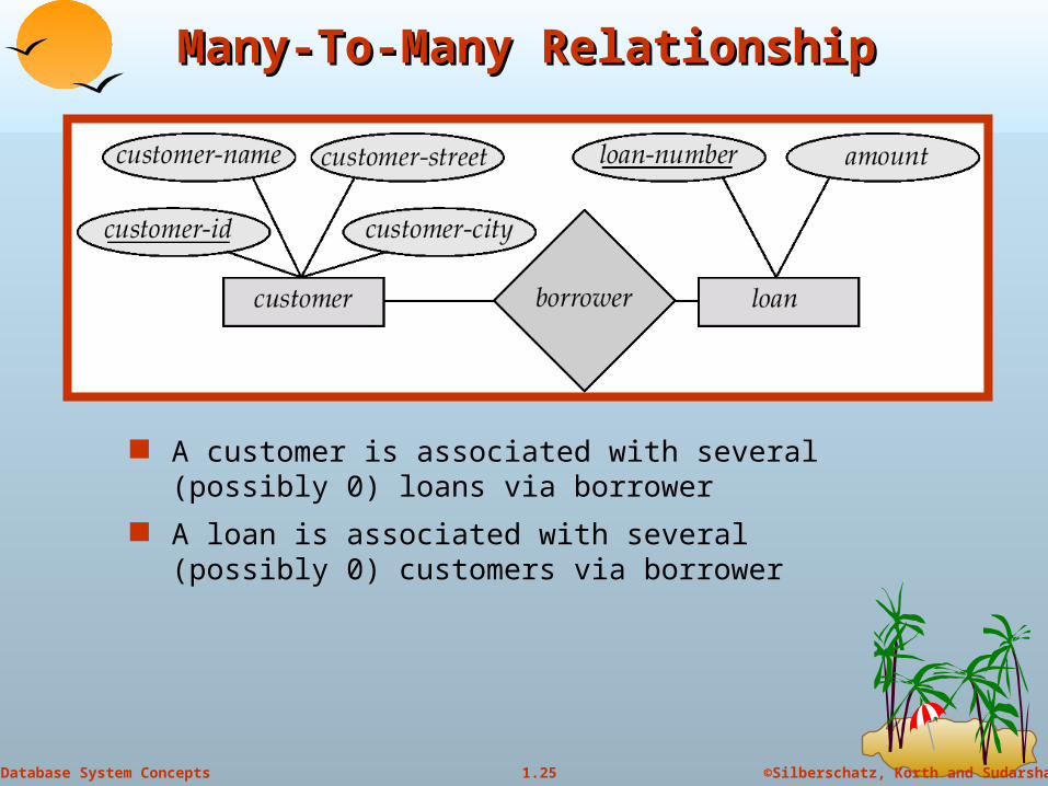
Many-To-Many RelationshipMany-To-Many Relationship
A customer is associated with several (possibly 0) loans via borrower
A loan is associated with several (possibly 0) customers via borrower
©Silberschatz, Korth and Sudarshan1.26Database System Concepts
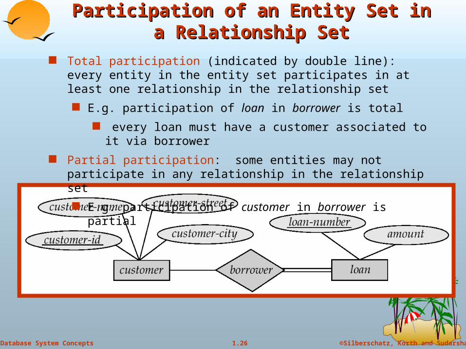
Participation of an Entity Set in a Participation of an Entity Set in a Relationship SetRelationship Set
Total participation (indicated by double line): every entity in the entity set participates in at least one relationship in the relationship set
E.g. participation of loan in borrower is total
every loan must have a customer associated to it via borrower
Partial participation: some entities may not participate in any relationship in the relationship set
E.g. participation of customer in borrower is partial
©Silberschatz, Korth and Sudarshan1.27Database System Concepts
KeysKeys
A super key of an entity set is a set of one or more attributes whose values uniquely determine each entity.
A candidate key of an entity set is a minimal super key Customer-id is candidate key of customer
account-number is candidate key of account
Although several candidate keys may exist, one of the candidate keys is selected to be the primary key.
©Silberschatz, Korth and Sudarshan1.28Database System Concepts
Keys for Relationship SetsKeys for Relationship Sets
The combination of primary keys of the participating entity sets forms a super key of a relationship set. (customer-id, account-number) is the super key of depositor
NOTE: this means a pair of entity sets can have at most one relationship in a particular relationship set.
Must consider the mapping cardinality of the relationship set when deciding the what are the candidate keys
Need to consider semantics of relationship set in selecting the primary key in case of more than one candidate key
©Silberschatz, Korth and Sudarshan1.29Database System Concepts
Design IssuesDesign Issues
Use of entity sets vs. attributesChoice mainly depends on the structure of the enterprise being modeled, and on the semantics associated with the attribute in question.
Use of entity sets vs. relationship setsPossible guideline is to designate a relationship set to describe an action that occurs between entities
Binary versus n-ary relationship setsAlthough it is possible to replace any nonbinary (n-ary, for n > 2) relationship set by a number of distinct binary relationship sets, a n-ary relationship set shows more clearly that several entities participate in a single relationship.
Placement of relationship attributes
©Silberschatz, Korth and Sudarshan1.30Database System Concepts
Weak Entity SetsWeak Entity Sets
An entity set that does not have a primary key is referred to as a weak entity set.
The existence of a weak entity set depends on the existence of a identifying entity set it must relate to the identifying entity set via a total, one-to-many
relationship set from the identifying to the weak entity set
Identifying relationship depicted using a double diamond
The discriminator (or partial key) of a weak entity set is the set of attributes that distinguishes among all the entities of a weak entity set.
The primary key of a weak entity set is formed by the primary key of the strong entity set on which the weak entity set is existence dependent, plus the weak entity set’s discriminator.
©Silberschatz, Korth and Sudarshan1.31Database System Concepts
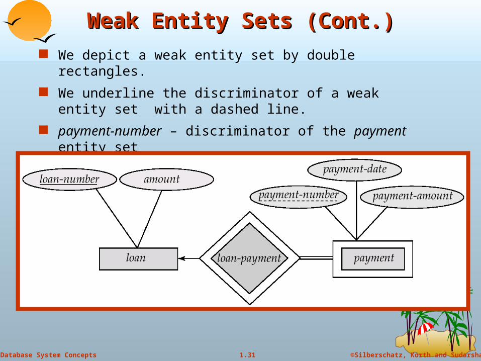
Weak Entity Sets (Cont.)Weak Entity Sets (Cont.) We depict a weak entity set by double rectangles.
We underline the discriminator of a weak entity set with a dashed line.
payment-number – discriminator of the payment entity set
Primary key for payment – (loan-number, payment-number)
©Silberschatz, Korth and Sudarshan1.32Database System Concepts
Weak Entity Sets (Cont.)Weak Entity Sets (Cont.)
Note: the primary key of the strong entity set is not explicitly stored with the weak entity set, since it is implicit in the identifying relationship.
If loan-number were explicitly stored, payment could be made a strong entity, but then the relationship between payment and loan would be duplicated by an implicit relationship defined by the attribute loan-number common to payment and loan

ExampleExample
©Silberschatz, Korth and Sudarshan1.34Database System Concepts
Silberschatz 2.3Silberschatz 2.3
Construct an E-R diagram for a hospital with a set of patients and a set of medical doctors. Associate with each patient a log of various tests and examinations conducted.
©Silberschatz, Korth and Sudarshan1.35Database System Concepts
SpecializationSpecialization
Top-down design process; we designate subgroupings within an entity set that are distinctive from other entities in the set.
These subgroupings become lower-level entity sets that have attributes or participate in relationships that do not apply to the higher-level entity set.
Depicted by a triangle component labeled ISA (E.g. customer “is a” person).
Attribute inheritance – a lower-level entity set inherits all the attributes and relationship participation of the higher-level entity set to which it is linked.
Construct an E-R diagram for a hospital with a set of patients and a set of medical doctors. Associate with each patient a log of various tests and examinations conducted.

©Silberschatz, Korth and Sudarshan1.36Database System Concepts
Specialization ExampleSpecialization Example
©Silberschatz, Korth and Sudarshan1.37Database System Concepts
GeneralizationGeneralization
A bottom-up design process – combine a number of entity sets that share the same features into a higher-level entity set.
Specialization and generalization are simple inversions of each other; they are represented in an E-R diagram in the same way.
The terms specialization and generalization are used interchangeably.

ExampleExample
©Silberschatz, Korth and Sudarshan1.39Database System Concepts
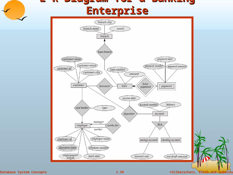
E-R Diagram for a Banking EnterpriseE-R Diagram for a Banking Enterprise
©Silberschatz, Korth and Sudarshan1.40Database System Concepts
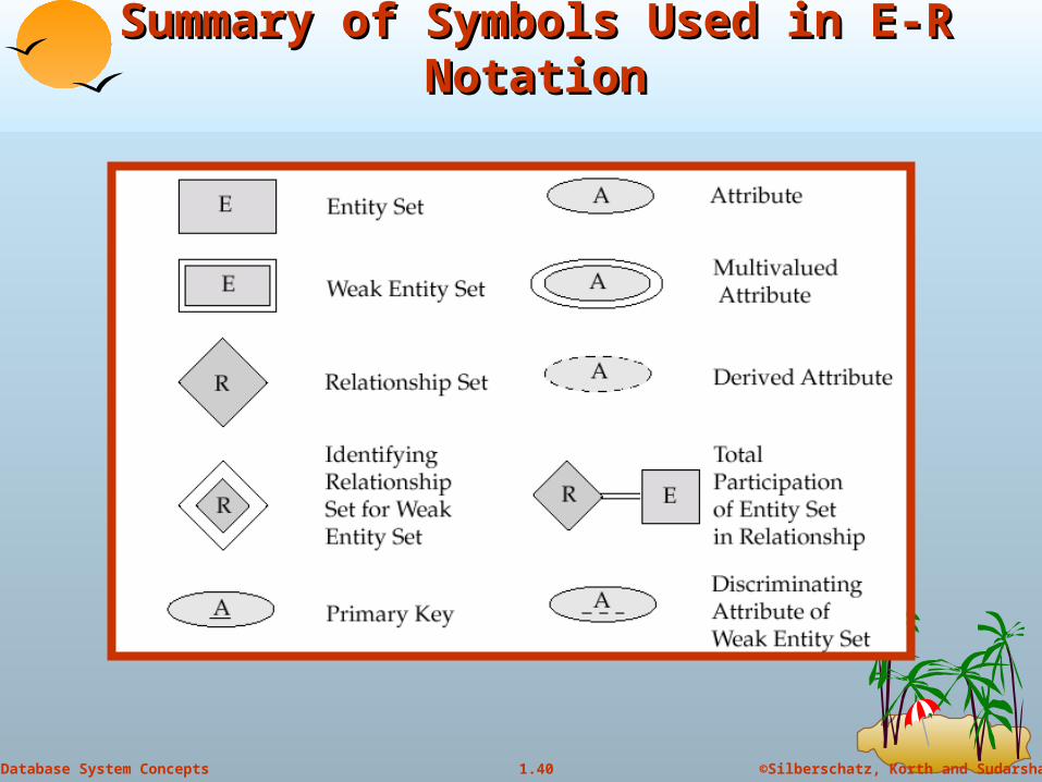
Summary of Symbols Used in E-R Summary of Symbols Used in E-R NotationNotation
©Silberschatz, Korth and Sudarshan1.41Database System Concepts
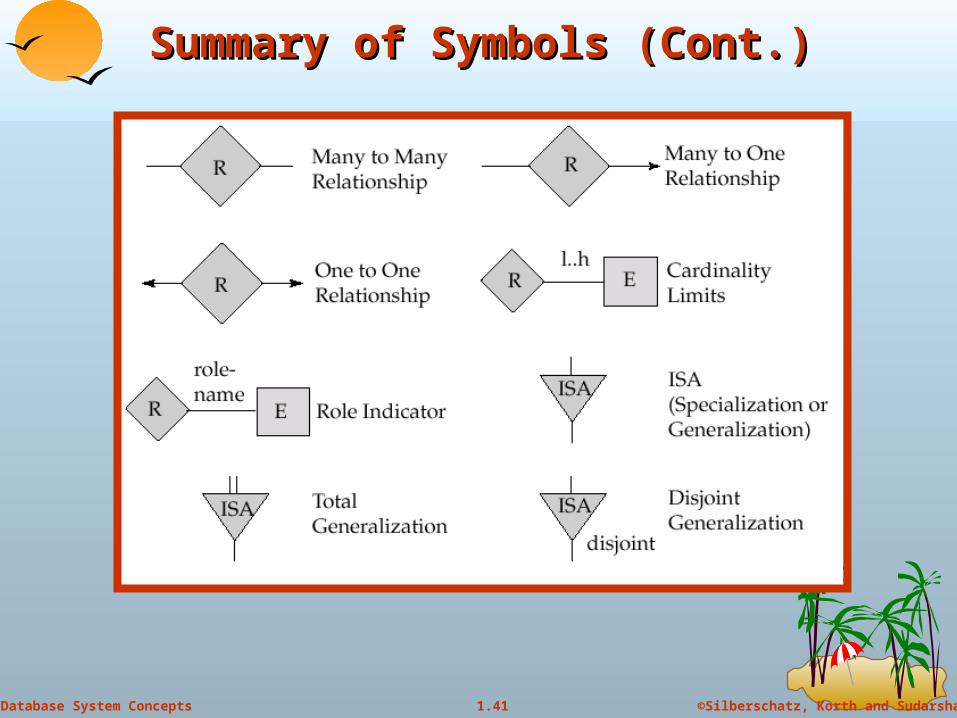
Summary of Symbols (Cont.)Summary of Symbols (Cont.)
©Silberschatz, Korth and Sudarshan1.42Database System Concepts
Reduction of an E-R Schema to TablesReduction of an E-R Schema to Tables
Primary keys allow entity sets and relationship sets to be expressed uniformly as tables which represent the contents of the database.
A database which conforms to an E-R diagram can be represented by a collection of tables.
For each entity set and relationship set there is a unique table which is assigned the name of the corresponding entity set or relationship set.
Each table has a number of columns (generally corresponding to attributes), which have unique names.
Converting an E-R diagram to a table format is the basis for deriving a relational database design from an E-R diagram.
©Silberschatz, Korth and Sudarshan1.43Database System Concepts
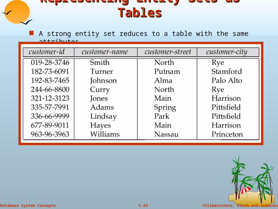
Representing Entity Sets as TablesRepresenting Entity Sets as Tables
A strong entity set reduces to a table with the same attributes.

©Silberschatz, Korth and Sudarshan1.44Database System Concepts
Representing Weak Entity SetsRepresenting Weak Entity Sets
A weak entity set becomes a table that includes a column for the primary key of the identifying strong entity set
©Silberschatz, Korth and Sudarshan1.45Database System Concepts
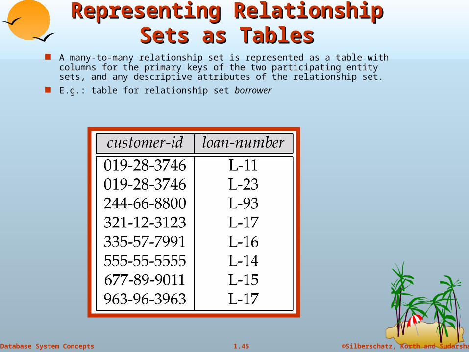
Representing Relationship Sets as Representing Relationship Sets as TablesTables
A many-to-many relationship set is represented as a table with columns for the primary keys of the two participating entity sets, and any descriptive attributes of the relationship set.
E.g.: table for relationship set borrower
©Silberschatz, Korth and Sudarshan1.46Database System Concepts
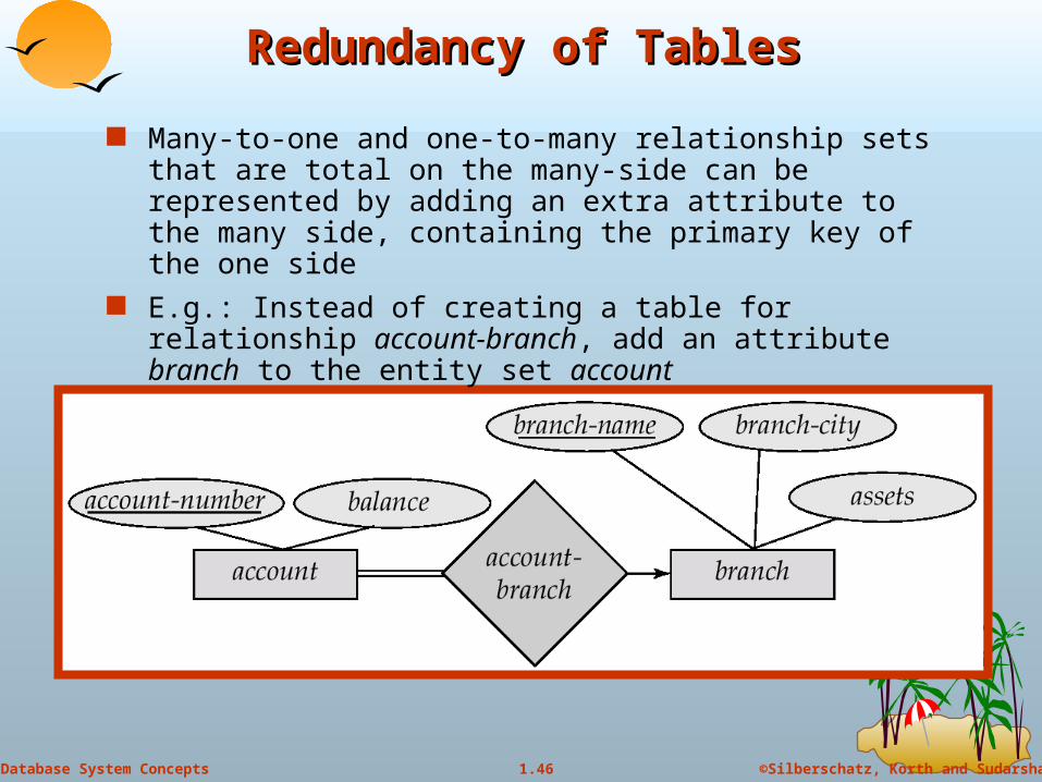
Redundancy of TablesRedundancy of Tables
Many-to-one and one-to-many relationship sets that are total on the many-side can be represented by adding an extra attribute to the many side, containing the primary key of the one side
E.g.: Instead of creating a table for relationship account-branch, add an attribute branch to the entity set account
©Silberschatz, Korth and Sudarshan1.47Database System Concepts
Redundancy of Tables (Cont.)Redundancy of Tables (Cont.)
For one-to-one relationship sets, either side can be chosen to act as the “many” side That is, extra attribute can be added to either of the tables
corresponding to the two entity sets
If participation is partial on the many side, replacing a table by an extra attribute in the relation corresponding to the “many” side could result in null values
The table corresponding to a relationship set linking a weak entity set to its identifying strong entity set is redundant. E.g. The payment table already contains the information that would
appear in the loan-payment table (i.e., the columns loan-number and payment-number).
©Silberschatz, Korth and Sudarshan1.48Database System Concepts
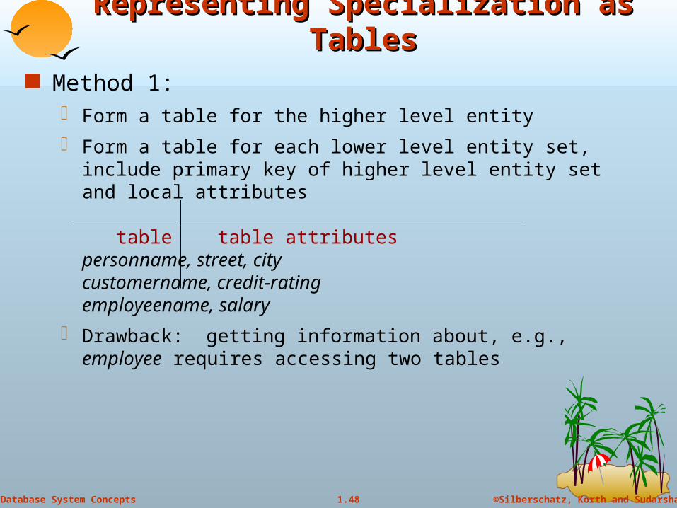
Representing Specialization as TablesRepresenting Specialization as Tables Method 1:
Form a table for the higher level entity
Form a table for each lower level entity set, include primary key of higher level entity set and local attributes
table table attributespersonname, street, city customername, credit-ratingemployeename, salary
Drawback: getting information about, e.g., employee requires accessing two tables
©Silberschatz, Korth and Sudarshan1.49Database System Concepts
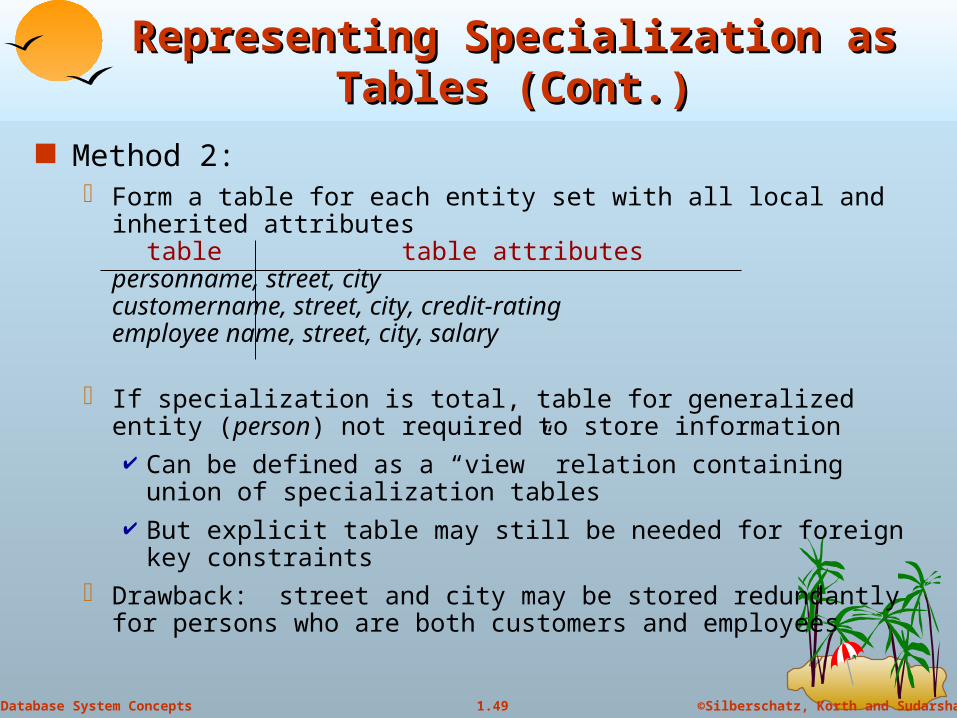
Representing Specialization as Tables Representing Specialization as Tables (Cont.)(Cont.)
Method 2: Form a table for each entity set with all local and inherited
attributestable table attributes
personname, street, citycustomername, street, city, credit-ratingemployee name, street, city, salary
If specialization is total, table for generalized entity (person) not required to store information Can be defined as a “view” relation containing union of
specialization tables But explicit table may still be needed for foreign key constraints
Drawback: street and city may be stored redundantly for persons who are both customers and employees
ExampleExample
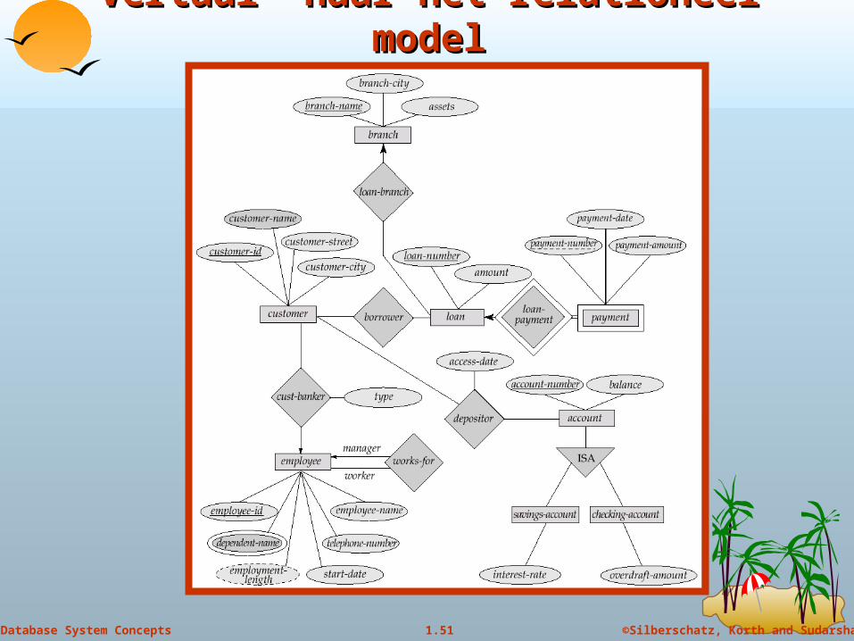
©Silberschatz, Korth and Sudarshan1.51Database System Concepts
Vertaal naar het relationeel modelVertaal naar het relationeel model