Embed Size (px)
Citation preview
Manuale utente - User manual
FI 05 ZS - FI 05 ZW - FI 12 ZS - FI 12 ZW - FI 25 ZS - FI 25 ZW
Sintesi
Sintesi 05-12-25
ATTENZIONE: Prima di usare questi apparecchi, leggere attentamente le istruzioni che seguono. Spotlight srl non potrà essere ritenuta responsabile di danni derivanti dalla non osservanza di dette istruzioni.
SAFETY WARNING: Before using this product, read the present instructions carefully.Spotlight srl will not be responsible for damage resulting from instructions not being followed.
2
ACHTUNG: Vor Inbetriebnahme zuerst die folgenden Anweisungen sorgfältig lesen.Bei nicht Beachtung übernimmt Spotlight srl keinerlei Haftung.
ATTENTION: Avant d’utiliser le projecteur, lisez attentivement les instructions suivantes.Spotlight srl ne pourra être tenu responsable pour les dommages resultants de la non-observation de ces instructions-ci.
Figura 05-12-25
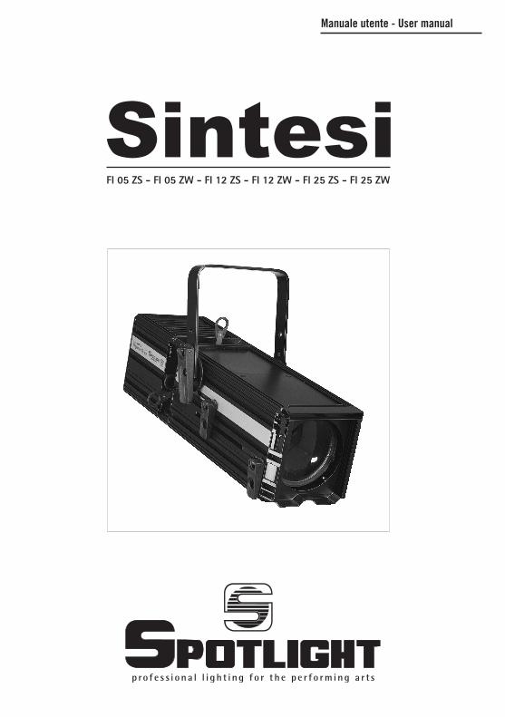
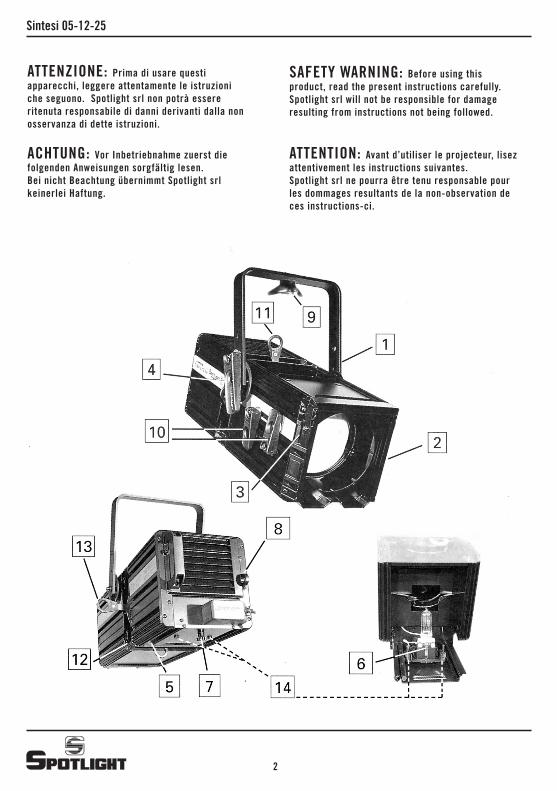
1 - DESCRIZIONE DEL FARORiferendoci alle immagini1 Staffa di sospensione2 Guide porta accessori con tettuccio di ritenzione3 Molla per bloccaggio tettuccio4 Maniglia a leva per regolazione inclinazione del faro5 Pomello per apertura bacinella portalampada6 Slitta con zoccolo porta lampada7 Pomolo per regolazione posizione lampada8 Staffa per ancoraggio catena di sicurezza9 Galletto per fissaggio e regolazione puntamento10 Maniglie a leva per regolazione lenti (zoom)11 Leve comando ghigliottine12 Pomolo per bloccaggio inclinazione ghigliottine13 Leva per inclinazione ghigliottine14 Viti regolazione lampada
2 - GENERALITÀIl proiettore in Vs possesso risponde alle Direttive Europee 2006/95/CE, 2004/108/CE e 2011/65/UE.La targhetta che è localizzata sulla fianco del faro, contiene le seguenti informazioni:• modello• massima tensione di alimentazione in V• massima potenza della lampada in W• indice di protezione IP• massima temperatura ambiente ammissibile in °C• massima temperatura del corpo del faro in °C• distanza minima da ogni superficie infiammabile• informazioni per riconoscere la posizione 0°del faro: quando la punta della freccia è rivolta verso l‘alto
• angolomassimodiinclinazioneversol‘altoeverso il basso. Questi limiti, imposti dal costruttore della lampada, non devono essere superati pena una riduzione della vita utile della lampada o il deterioramento del faro.
3 - ISTALLAZIONEII faro può essere usato sia sospeso, sia montato su cavalletto.ATTENZIONE!NON ISTALLARE IL FARO SU SUPERFICI NORMAL MENTE INFIAMMABILI.La distanza minima a cui occorre tenere il faro da superfici suscettibili di infiammarsi è data dalla tar ghetta.ATTENZIONE! SOSTITUIRE LA LAMPADA E/O LA LENTE SE
VISI BILMENTE DANNEGGIATE.Sempre a scopo di sicurezza occorre far use della catena di sicurezza tra il faro e traliccio di sospen sione.3.1 - AccessoriGli accessori previsti per questo faro sono elencati nel listino e possono essere montati tramite le guide 2.3.1.1 - CambiacoloriInserire la flangia dei cambiacolori nell’apposita guida finchè non è possibile richiudere it tettuccio e farscattare la molla di ritegno. Collegare la fune di sicu rezza al gancio apposito del faro.3.1.2 - Alette paraluceMontarle come nel caso del cambiacolori.
4 - CAMBIO DELLA LAMPADAPer motivi di sicurezza, scollegare sempre l’apparec chio dalla rete di alimentazione prima di aprirlo per cambiare la lampada. Aprire la bacinella portalam pada tramite il pomello 5. Inserire la lampada nello zoccolo curando di non toccare il vetro. Poiché la nuova lampada potrebbe avere un differente centro luce, si può effettuare il centraggio tramite il pomello 7. ATTENZIONE!PER MONTARE UNA LAMPADA DA 1000 W (CON IL CENTRO LUCE PIÙ BASSO) AL POSTO DI UNA 1200 W, OCCORRE SPOSTARE IL PIATTELLO CON LO ZOCCOLO PORTALAMPADA, SVITANDO DI UNA UGUALE QUANTITÀ LE DUE VITI 14 ED AGENDO POI SUL POMELLO 7.
5 - CONNESSIONI ELETTRICHEII vostro faro è stato progettato per una tensione di alimentazione massima di 240 V. II cavo di alimenta zione risponde alle norme CEI 20-35. Occorre però essere sicuri che la terra sia sempre collegata.
6 - PUNTAMENTOTramite la maniglia laterale 4 si può allentare il bloc caggio del faro in una certa posizione e modificare la sua inclinazione. Lo stesso si può fare riguardo alla rotazione dell’asse verticale allentando il galletto 9. Con le maniglie a leva 10 si effettua la regolazione dello zoom, allargando o stringendo il fascio di luce . Tramite le quattro ghigliottine 11 si può tagliare il fascio di luce per effetti speciali; mediante la leva 13 si può quindi ruotare tutto il gruppo delle ghigliotti ne, che viene quindi bloccato dal pomello 12.
3
Sintesi 05-12-25
4
7 - PULIZIAPer una maggiore resa del faro, occorre tener puliti il più possibile le lenti e lo specchio. Per far questo, dopo aver scollegato il faro dalla rete di alimentazio ne, si può aprirlo per pulire con uno straccio soffice inumidito con alcool sia la !ente che lo specchio.
8 - TIPO DI LAMPADAVEDERE TABELLA RIPORTATA IN ULTIMA PAGINA. ATTENZIONE!COLLEGARE SEMPRE L’APPARECCHIO AD UNA LI NEA DI ALIMENTAZIONE ELETTRICA CHE SIA PRO TETTA CON UN FUSIBILE SCELTO OPPORTUNAMEN TE SECONDO LE INDICAZIONI FORNITE DAL COSTRUTTORE DELLE LAMPADE UTILIZZATE.
9 - MANUTENZIONESottoporre il faro a revisione almeno una volta al l’anno per controllare l’integrità della parti elettriche e meccaniche.
10 - RICICLAGGIOIl prodotto deve essere riciclato o smaltito secondo la direttiva 2002/96/CE
Figura 05-12-25
1 - DESCRIPTION OF THE PROJECTORRefer to figures1 Suspension clamp2 Accessory guides with retaining clip3 Spring-loaded latch lock4 Lever handle for tilt regulation5 Lamp holder tray access knob6 Carriage with lamp socket7 Lamp position adjustment knob8 Safety chain anchorage clamp9 Wing nut for locking and adjusting projector focus10 Lever handle for lens adjustment (Zoom)11 Levers for shutters adjustment12 Shutters rotation locking knob13 Shutters rotation lever14 Lamp adjusting screws
2 - GENERALThe luminaire you have bought complies to 2006/95/EC, 2004/108/EC and 2011/65/EU European Directives.The label located on the side of the projector contains the following information:•model•maximum supply voltage in V•maximum power of the projector in W•the index of protection IP•maximum temperature of the environment admitted
in °C•maximum temperature of the projector body in °C•minimum distance from any inflammable surface•information to find the position 0° of the projector:
when the tip of the arrow points upwards •maximum angle of inclination upwards and
downwards. These limits, imposed by the lamp manufacturer, should not be exceeded as they would reduce the projector’s useful life or lead to its deterioration.
3 - INSTALLATIONThe projector can be either suspended or mounted on a stand.WARNING!DO NOT INSTALL THE PROJECTOR ON SURFACES WHICH ARE USUALLY INFLAMMABLE.The minimum distance at which the projector must be kept from easily inflammable surfaces is indicated on the label.WARNING!REPLACE THE LAMP AND/OR LENS IF VISIBLY
DAMAGED.For safety reasons always use the safety chain between the projector and the suspension truss.3.1 - AccessoriesThe accessories estimated for this projector are listed in the price list and can be mounted by inserting into guides 2.3.1.1. - Colour changerInsert the flange of the colour changer into its guideso that the latch remains closed and the retaining spring is released. Connect the safety cable to the special hook of the projector.3.1.2. - BarndoorMount them in the same way as the colour changer.
4 - CHANGING THE LAMPFor safety reasons always disconnect the projector from the mains before opening it to change the lamp. Open the projector lamp holder tray by means of knob 5. Insert the lamp into the socket taking care not to touch the glass. Since the new lamp may have a different centre of light, it may be centred with knob 7.WARNING!TO MOUNT A 1000 W LAMP (WITH A LOWER CENTRE OF LIGHT) IN LIEU OF A 1200 W LAMP, THE PAN FITTED WITH THE LAMP HOLDER MUST BE SHIFTED, BY UNIFORMLY LOOSENING THE TWO SCREWS 14 AND THEN ACTING ON KNOB 7.
5 - ELECTRICAL CONNECTIONSYour projector has been designed for a maximum voltage of 240V. The power cable complies with standards CEI 20-35. However one must make sure that the ground is always connected.
6 - FOCUS AND REGULATIONUsing the side handle 4 it is possible to loosen the projector when it is locked in a certain position and thus change its inclination. The same can be done as regards its rotation with respect to the vertical axis by loosening wing nut 9. The zoom is adjusted with lever handles 10, by widening or narrowing the beam of light. The beam of light can be cut with the four shutters 11 to obtain special effects.
7 - CLEANINGFor utmost projector performance, both the lens and the reflector must be kept as clean as possible. To do so, after disconnecting the projector from the mains, it can
5
Sintesi 05-12-25
6
be opened and both the lens and reflector cleaned with a soft cloth dampened with alcohol.
8 - TYPE OF LAMPSEE TABLE ON LAST PAGEWARNING!ALWAYS CONNECT THE PROJECTOR TO A MAIN WHICH IS PROTECTED BY A SUITABLE ELECTRIC FUSE SELECTED ACCORDING TO THE INSTRUCTIONS SUPPLIED BY THE MANUFACTURER OF THE LAMPS USED.
9 - MAINTENANCEThe projector must be serviced at least once a year to check the integrity of its electrical and mechanical parts.
10 - RECYCLINGThe product must be recycled or disposed of, according to Directive 2002/96/CE.
Figura 05-12-25
1- BESCHREIBUNG DES STRAHLERSBezug: Abb.1 Aufhängbügel2 Zubehörhalterungen mit Feststellhaube3 Haubenschnappverschluß4 Hebel zur Einstellung der Strahlerneigung5 Knopf zur Öffnung der Lampenschale6 Wagen mit Lampenfassung7 Knauf zur Positionseinstellung der Lampe8 Bügel zur Verankerung der Sicherheitskette9 Flügelmutter zum Feststellen und Regulieren der Ausrichtung10 Linseneinstellhebel (Zoom)11 Hebel zur Blendeneinstellung12 Knauf zur Feststellung der Blendenneigung13 Hebel zur Blendenneigung14 Schrauben zur Lampeneinstellung
2- ALLGEMEINESDer gekaufte Scheinwerfer ist gemäß der Europäischen Richtlinien 2006/95/EG, 2004/108/EG und 2011/65/EU hergestellt.Das Kennschild auf der Strahlerrückseite enthält die folgenden Informationen:•Modell•Maximale Zufuhrspannung in V•Maximalleistung der Lampe in W•IP-Schutzindex•Maximal gestattete Raumtemperatur in °C•Maximale Strahlerkörpertemperatur in °C•Mindestabstand von brennbaren Oberflächen•Informationen zur Erkennung der 0°-Stellung des
Strahlers: wenn die Pfeilspitze nach oben zeigt•Maximaler Neigungswinkel nach unten und oben.
Diese Grenzen, die vom Lampenhersteller vorgegeben werden, dürfen nicht überschritten werden; andernfalls verkürzt sich die Lebensdauer der Lampe, oder der Strahler wird beschädigt.
3- INSTALLATIONDer Strahler kann sowohl aufgehängt als auch auf einen Dreifuß montiert werden. ACHTUNG!DER STRAHLER DARF NICHT AUF NORMAL BRENNBAREN OBERFLÄCHEN INSTALLIERT WERDEN. Der Mindestabstand von brennbaren Oberflächen ist auf dem Kennschild angegeben. ACHTUNG!ERSETZEN SIE DIE LAMPE UND / ODER DIE SAMMELLINSE, WENN SIE SICHTBAR BESCHÄDIGT SIND.
Ebenso muß sicherheitshalber bei aufgehängten Lampen die Sicherheitskette zwischen Strahler und Aufhängstruktur angebracht werden.3.1. - ZubehörDas für diesen Strahler vorgesehene Zubehör ist in der Liste aufgeführt und kann an den Halterungen 2 montiert werden.3.1.1. - FarbfilterDen Flansch der Farbfilter in die dafür vorgesehene Halterung einfügen, bis die Haube geschlossen werden kann und der Schnappverschluß zuschnappt. Das Sicherheitskabel mit dem dafür vorgesehenen Haken am Strahler verbinden.3.1.2. - AbblendflügelEbenso wie die Farbfilter montieren.
4 - LAMPENWECHSELZiehen Sie aus Sicherheitsgründen stets den Netzstecker, bevor Sie den Apparat für den Lampenwechsel öffnen. Öffnen Sie die Lampenschale, indem Sie auf den dafür vorgesehenen Knopf 5 drücken. Die Lampe in die Fassung einsetzen; dabei darauf achten, das Glas nicht zu berühren. Da die neue Lampe einen anderen Lichtmittelpunkt haben könnte, kann durch den Knauf 7 das Licht zentriert werden. ACHTUNG!UM ANSTELLE EINES 1200 W LEUCHTMITTELS EIN 1000 W LEUCHTMITTEL (MIT NIEDRIGEREM LICHTMITTELPUNKT) MONTIEREN ZU KÖNNEN, MUSS DIE TRÄGERSCHEIBE MIT DER LAMPENFASSUNG NACH OBEN VERSCHOBEN WERDEN, INDEM DIE BEIDEN SCHRAUBEN 14 GLEICHSTARK ANGEDREHT WERDEN MUESSEN, UND DAS LICHT DANN DURCH DEN KNAUF 7 ZENTRIERT WIRD.
5 - ELEKTRISCHE ANSCHLÜSSEIhr Strahler ist für eine maximale Zufuhrspannung von 240 V geplant. Das Netzkabel entspricht den Anforderungen der Normen CEI 20-35. Achten Sie jedoch bitte darauf, daß die Erdung stets angeschlossen ist.
6 - EINSTELLUNGDurch den seitlichen Hebel 4 kann die Feststellung des Stdhiers in einer bestimmten Position gelockert werden, um seine Neigung zu ändern. Auf ähnliche Weise kann auch die Drehung bezüglich der senkrechten Achse geändert werden, indem man die Flügelmutter 9 lockert. Mit den Hebeln 10 kann der Zoom eingestellt werden,
7
Sintesi 05-12-25
indem der Lichtstrahl gebündelt oder verbreitert wird. Durch die vier Blenden 11 kann der Lichtstrahl zum Erzielen von Spezialeffekten geschnitten werden; durch den Hebel 13 kann daraufhin die gesamte Blendengruppe gedreht werden; die Einstellung kann dann durch den Knauf 12 festgestellt werden.
7 - REINIGUNGFür eine maximale Ausschöpfung der Strahlerleistung sollten‘die Sammellinse und der Spiegel so sauber wie möglich gehalten werden. Dazu kann der Strahler -nachdem man den Netzstecker gezogen hat -geöffnet werden, woraufhin mit einem weichen, mit Alkohol befeuchteten Tuch die Sammellinse und der Diffusor gereinigt werden können.
8 - LAMPENTYPSIEHE TABELLE AUF DER LETZTEN SEITE. ACHTUNG!DEN APPARAT NUR AN ELEKTRISCHE STROMNETZE ANSCHLIESSEN, DIE DURCH EINE HOCHWERTIGE SICHERUNG GESICHERT SIND, DIE DEN ANGABEN DES LAMPENHERSTELLERS ENTSPRICHT.
9 - WARTUNGDer Strahler sollte mindestens einmal im Jahr gewartet werden, um die Funktionstüchtigkeit der elektrischen und mechanischen Bauteile zu überprüfen.
10 - ENTSORGUNGDas Produkt muss entsprechend den Richtlinien 2002/96/CE wiederverwendet oder entsorgt werden.
8
Figura 05-12-25
raisons de sécurité, il faut utiliser la chaîne de sécurité entre le projecteur et le treillis de suspension3.1 - AccessoiresLes accessoires prévus pour ce projecteur sont énumérés dans le catalogue et peuvent être montés au moyen des guidages 2.3.1.1 - Changement de couleursIntroduire la bride du changement de couleurs dans le guidage prévu à cet effet jusqu’à ce qu’il ne soitplus possible de refermer le clapet et de faire jouer le ressort de rétention. Relier les câbles de sécurité au crochet du projecteur.3.1.2 - Ailettes coupe-fluxProcéder au montage comme pour le changement de couleurs.
4 - CHANGEMENT DE LA LAMPEPour des raisons de sécurité, débrancher toujours l’appareil du réseau d’alimentation avant de l’ouvrir pour changer la lampe. Ouvrir la cuvette en actionnant le pommeau 5. Introduire la lampe dans le culot en ayant soin de ne pas toucher le verre. Comme la nouvelle lampe pourrait avoir un centre de lumière différent, il est possible d’effectuer le centrage au moyen du pommeau 7.ATTENTION!POUR MONTER UNE LAMPE DE 1000 W (AVEC UN CENTRE DE LUMIÈRE INFERIEUR) AU LIEU D’UNE LAMPE DE 1200 W, IL FAUT DÉPLACER LE PLATEAU AVEC LE CULOT DE LA DOUILLE EN DEVISSANT D’UNE MÊME TENSION LES DEUX VIS 14 ET EN ACTIONNANT ENSUITE LE POMMEAU 7.
5 - BRANCHEMENTS ELECTRIQUESCe projecteur est prévu pour une tension d’alimentation maximum de 240 V. Le cäble d’alimentation répond aux normes CEI 20-35. Il faut cependant être sûr que la terre soit toujours branchée.
6 - POINTAGEA l’aide de la poignée latérale 4, on peut desserrer le blocage du projecteur dans une certaine position et modifier son inclinaison. Il en va de même pour la rotation de l’axe vertical en desserrant l’écrou à oreille 9. Avec les poignées à levier 10, on effectue le réglage du zoom, en élargissant ou en resserrant le faisceau de lumière. A l’aide des quatre écrans 11, on peut couper le faisceau de lumière pour des effets spéciaux; avec le levier 13, on peut enfin faire tourner tout le groupe des
1 - DESCRIPTION DU PROJECTEURD’après les dessins1 Etrier de suspension2 Guidages porte-accessoires avecclapet de rétention3 Ressort pour blocage clapet4 Poignée à levier pour réglage inclinaison du projecteur5 Pommeau pour ouverture cuvette douille6 Coulisse avec culot douille7 Pommeau pour réglage position lampe8 Etrier pour fixation chaîne de sécurité9 Ecrou à oreille pour fixation et réglage pointage10 Poignées à levier pour réglage lentilles (zoom)11 Quatre leviers de commande écrans12 Pommeau pour blocage inclinaison écrans13 Levier pour inclinaison écrans14 Vis pour réglage lampe
2 - GENERALITESLe projecteur que vous avez acheté est conforme aux Directives Européennes 2006/95/CE, 2004/108/CE et 2011/65/UE. L’étiquette figurant sur le côté du projecteur contient les informations suivantes:modèletension maximum d’alimentation en Vpuissance maximum de la lampe en Windice de protection IPtempérature ambiante maximale admissible en °Ctempérature maximale du corps du projecteur en °Cdistance minimum de toute surface inflammableinformations permettant de reconnaître la position 0° du projecteur: quand la pointe de la flèche est tournée vers le hautangle maximum d’inclinaison vers le haut et vers le bas. Ces limites, imposées par le constructeur de la lampe, ne doivent pas être dépassées sous peine de réduire la durée de vie de la lampe ou de détériorer le projecteur.
3 - INSTALLATIONLe projecteur peut être utilisé soit suspendu soit monté sur un chevalet.ATTENTION!NE PAS POSER LE PROJECTEUR SUR DESSURFACES NORMALEMENT INFLAMMABLES.La distance minimum à laquelle il convient de placer le projecteur des surfaces susceptibles de s’enflammer est indiquée sur l’étiquette. ATTENTION!REMPLACER LA LAMPE ET/OU LA LENTILLE SI CELLES-CI SONT VISIBLEMENT ENDOMMAGÉES. Toujours pour des
9
Sintesi 05-12-25
écrans qui est donc bloqué par le pommeau 12.
7 - NETTOYAGEPour un rendement optimal du projecteur, il faut que les lentilles et le miroir soient toujours très propres. Pour ce faire, après avoir débranché le projecteur du réseau d’alimentation, on peutl’ouvrir pour nettoyer avec un chiffon doux humidifié d’alcool la lentille ou le miroir.
8 - TYPE DE LAMPEVOIR TABLEAU INDIQUÉ EN DERNIÈRE PAGE. ATTENTION!BRANCHER TOUJOURS L’APPAREIL SUR UNE LIGNE D’ALIMENTATION ÉLECTRIQUE PROTÉGÉE PAR UN FUSIBLE APPROPRIÉ, SELON LES INDICATIONS FOURNIES PAR LE CONSTRUCTEUR DES LAMPES UTILISÉES.
9 - ENTRETIENFaire réviser le projecteur au moins une fois par an pour contrôler l’intégralité des parties électriques et mécaniques.
10 - RECYCLAGELe produit doit etre recyclé, ou éliminé suivant les directives 2002/96/CE
10
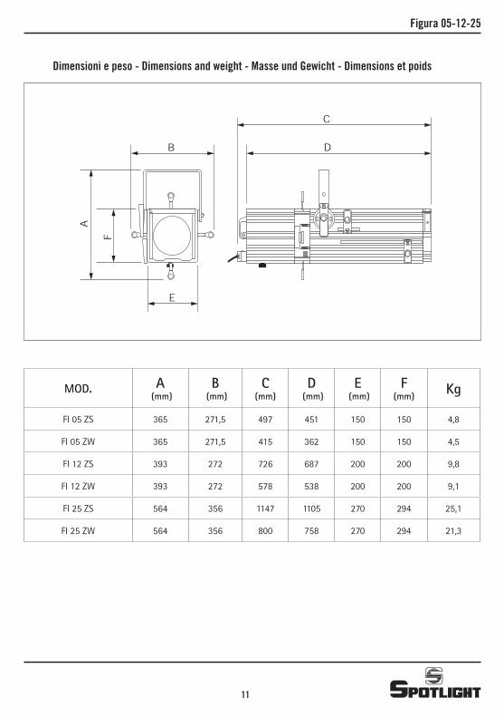
Figura 05-12-25
Dimensioni e peso - Dimensions and weight - Masse und Gewicht - Dimensions et poids
MOD. A (mm)
B (mm)
C(mm)
D (mm)
E (mm)
F (mm) Kg
FI 05 ZS 365 271,5 497 451 150 150 4,8
FI 05 ZW 365 271,5 415 362 150 150 4,5
FI 12 ZS 393 272 726 687 200 200 9,8
FI 12 ZW 393 272 578 538 200 200 9,1
FI 25 ZS 564 356 1147 1105 270 294 25,1
FI 25 ZW 564 356 800 758 270 294 21,3
11
C
DB
F
A
E
Spotlight s.r.l. Via Sardegna 3
20098 S. Giuliano Milanese Milano - Italy
Tel. +39.02.98830.1 Fax +39.02.98830.22
E-mail: [email protected] www.spotlight.it
Figura 05-12-25
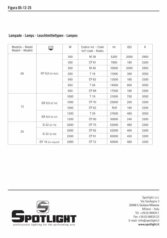
Lampade - Lamps - Leuchtmitteltypen - Lampes
Modello - ModelModell - Modèle
W Codice int. - CodeInt’l code - Kodex
lm t(h) K
05 GY 9,5 (LC 46,5)
300 M 38 5200 2000 2950
300 CP 81 7800 180 3200
500 M 40 10000 2000 2950
500 T 18 11000 360 3050
500 CP 82 13500 180 3200
650 T 26 14500 600 3050
650 CP 89 17500 180 3200
12
GX 9,5 (LC 55)
1000 T 19 21000 750 3050
1000 CP 70 25000 200 3200
1000 CP 63 Refl. 180 3200
GX 9,5 (LC 67)1200 T 29 27600 480 3050
1200 CP 90 30000 240 3200
25
G 22 (LC 75) 2000 CP 75 52000 480 3200
G 22 (LC 90)2000 CP 92 52000 400 3200
2500 CP 91 65000 450 3200
GY 16 (on request) 2000 CP 72 50000 480 3200


![Utilizzohelpguide.sony.net/cam/1510/v1/it/print.pdfUso del proiettore incorporato (modelli con proiettore) [44] Uso del proiettore per il computer o lo smartphone (modelli con proiettore)](https://img.pdfslide.tips/doc/110x75/5aaa7b3f7f8b9a90188e2b46/del-proiettore-incorporato-modelli-con-proiettore-44-uso-del-proiettore-per.jpg)