Embed Size (px)
Citation preview

SKY ELEVATOR
AC Series Lift Control System
USER MANUAL
F/7.5.5.02.67 R:10 1 /62 AC

AC SERIES LIFT CONTROL SYSTEM
USER MANUAL
VERSION: 1.10
�
SKY ELEVATOR
Ikitelli OSB Metal Iş San.Sit 19.Blok No:1Basakşehir-Istanbul / Turkey Tel: (90) (216) 549 11 21 Mobile: (90) (533) 293 96 56
e-mail: [email protected] www.sky-elevator.com
F/7.5.5.02.67 R:10
2 / 62
AC
CONTENTS GENERAL DESCRIPTION ................................................................................................................................. 5
A) COMPONENTS AND CONFIGURATIONS ............................................................................................ 5 B) PANEL VOLTAGE INFORMATION ....................................................................................................... 6 C) INPUTS AND OUTPUTS ........................................................................................................................... 6 D) SHAFT INFORMATION COLLECTION ................................................................................................ 7 E) SAFETY LINE STRUCTURE .................................................................................................................... 7
OUTPUT TERMINALS AND THE MEANINGS OF THE ABBREVIATI ONS .............................................. 9
CHAPTER 1:LCD SCREEN AND KEYPAD USAGE ........................................................................................ 11
1-A) STARTUP SCREENS ........................................................................................................................... 11 1-B) MAIN SCREEN..................................................................................................................................... 12 1-C) MONITORING OF INPUTS ................................................................................................................. 17 1-D) DEFINITION OF INPUTS .................................................................................................................... 22 1-E) MAIN MENU ......................................................................................................................................... 23 1-F) SETTING PARAMETERS .................................................................................................................... 24 1-G) GIVING CALLS BY KEYPAD ............................................................................................................. 27 1-H) SOFTWARE VERSION NUMBER ...................................................................................................... 27
CHAPTER 2:PARAMETERS............................................................................................................................. 28
2-A) P1-MAIN PARAMETERS .................................................................................................................... 28 2-B) P2-AUXILIARY PARAMETERS ......................................................................................................... 32 2-C) P3-TIMINGS ......................................................................................................................................... 39 2-D) P4-FLOOR PARAMETERS ................................................................................................................. 43
2-D-1) K1-SET DISPLAYS.......................................................................................................................... 43 2-D-2) K2-SET DOOR A and K3-SET DOOR B .......................................................................................... 44 2-D-3) K4-CABIN CALLS........................................................................................................................... 45 2-D-4) K5-HALL CALLS............................................................................................................................. 46 2-D-5) K6-ENCODER PULSE OF FLOORS............................................................................................... 46 2-D-6) K7-GENERAL PULSE..................................................................................................................... 47 2-D-7) K8-CALL REGISTER PERIODS...................................................................................................... 48
2-E) P5-MAINTENANCE TIME .................................................................................................................. 48 2-F) P6-OUTPUT DEFINITIONS ................................................................................................................. 49 2-G) P7-INPUT DEFINITIONS .................................................................................................................... 52 2-H) P8-DATE & TIME ................................................................................................................................ 52 2-I) P9-UTILITIES ........................................................................................................................................ 53
2-I-1) R1-DISPLAY UTILITIES................................................................................................................... 53 2-I-2) R2-FACTORY SETTINGS ................................................................................................................. 53 2-I-3) R3-SET ALL INPUTS........................................................................................................................ 53 2-I-4) R4-MODEM SETTINGS.................................................................................................................... 54 2-I-5) R5-RESET PULSES .......................................................................................................................... 54 2-I-6) R6-OTHER UTILITIES (Do NOT Use).............................................................................................. 54 2-I-7) R7-SET PASSWORD......................................................................................................................... 54 2-I-8) R8-COUNTER .................................................................................................................................. 55 2-I-9) R9-SECURITY ID ............................................................................................................................. 55 2-I-10) RA-ENCODER SETUP ................................................................................................................... 56
2-J) P0-MAX START .................................................................................................................................... 57 CHAPTER 3:ERROR LOG AND ERROR CODES ............................................................................................ 58
CHAPTER 4:VARIABLES AND LANGUAGE .................................................................................................. 61
CHAPTER 5:UCM SERVICE ............................................................................................................................ 62
5-A) U1-CLEAR ERROR.............................................................................................................................. 62 5-B) U2-UCM TEST ( SLB4 BOARD IS REQUIRED FOR ACT,ACS SERIES)....................................................... 62 5-C) U3-TEST TIME ..................................................................................................................................... 62 5-D) U4-TEST START .................................................................................................................................. 62 5-E) U5 -TEST COUNTER ........................................................................................................................... 62
F/7.5.5.02.67 R:10
3 / 62
AC
PREFACE AC Series Lift Control System has been designed to fulfill the needs of lift sector at new age. One of the main aims of this series is to integrate lift control system with today's advanced computer systems. AC Series Lift Control System is controlled by a 32-bit high performance microcontroller. Besides having all features of general lift control systems, AC Series can also communicate with a computer directly or via internet. By this way it is possible to access and observe all lift motion and edit parameters for authorized users by a computer. In this manual, you can find detailed information about using AC Series Lift Control System, technical documents and schematics. If you think that this manual is not enough or it is not compatible with hardware or software version of your system, you can download latest version of the manual from website of Sky Elevator (www.sky-elevator.com) or send an e-mail to request. We will continue to develop this product with your support and suggestions. Therefore, if you face any problem while using this product or if you have any suggestions to make it better, please inform us by e-mail ([email protected]).
Sky Elevator
F/7.5.5.02.67 R:10
4 / 62
AC
GENERAL DESCRIPTION
A) COMPONENTS AND CONFIGURATIONS Systems contain the following boards: ACS : It is the main controller board of ACS system. It contains microcontroller, LCD display and keypad, to manage system. This system works in electric lifts, has 2 programmable inputs and 4 programmable relay outputs. ACH : It is the main controller board of ACH system. It contains microcontroller, LCD display and keypad, to manage system. This system works in hydraulic lifts, has 2 programmable inputs and 3 programmable relay outputs. ACT : It is the main controller board of ACT system. It contains microcontroller, LCD display and keypad, to manage system. This system works in electric lifts, has 2 programmable inputs and 2 programmable relay and 1 transistor outputs. ACC : It is the car controller board that supports up to 64 floors. It gets cabin calls and signal inputs, collects information from switches and detectors placed on the car and transmits to main controller. It contains 3 (optionally 15) programmable relay outputs and 8 (optionally 16) programmable inputs. SCC : It is the car controller board that supports up to 16 floors. It gets cabin calls and signal inputs, collects information from switches and detectors placed on the car and transmits to main controller. It contains 1 programmable relay outputs and 8 programmable inputs. OUT : This board contains 4 programmable output relays. INP : This board contains 4 programmable inputs. ENI : Encoder terminals connection board. CSI : This is CAN interface board. One CSI is used to collect shaft information in ACH/ACT systems. If the controller works in a lift group then use second CSI board for group communication connection. ETH : Ethernet interface board. USB : USB interface board. RS232 : RS232 interface board. IDC : ERS connection interface board. IO : It is the I/O board for the call registers which contains 8 I/Os. (ACH/ACT) RTC : Real Time Clock board. (ACH and ACT Series) ACSK : Serial communication terminal board. ACPK : Parallel communication terminal board. (ACH and ACT Series) ETU : Computer connection board for Ethernet and USB. SW232 : GSM Modem connection board. F/7.5.5.02.67 R:10
5 / 62
AC
I. SERIAL CONFIGURATION In this configuration, all inputs and outputs of shaft are transmitted serially through CAN-Bus network except safety circuit. (Add CSI board in ACH and ACT Series)
II. PARALLEL CONFIGURATION ACH and ACT Series support this configuration. Controller communicates with car and landings in point to point connection. Add I/O board for command system and floor requirements and add CSI board in group lift. III. SERIAL CAR - PARALLEL LANDINGS CONFIGURATION ACH and ACT Series support this configuration with CSI board. Add I/O board depends on number of push-buttons in landings. IV. ERS (EKS) OPTION ESM/EGH (Gearless): Mainboard of Electronic Rescue System. It contains microcontroller circuit and has two serial communication interfaces for controller board of panel and motor inverter boards. EPS: Power supply board of Electronic Rescue System. It also charges batteries in normal mode. EMD: Motor driver board. It drives 3-phase lift motor in rescue mode. APS : Battery charge board of ERS system. Use in systems with UPS + Battery. B) PANEL VOLTAGE INFORMATION
a. Safety Circuit Voltage: Depends on the contactor coil voltage. Maximum allowed voltage is 230V AC.
b. Signal Voltage: 24V DC is used for signal lamps and control of relays on the boards. The current of this supply is mainly determined by the current requirements of the push-buttons used in the system.
c. Microcontroller Voltage: 10V AC is required for the power supply of the microcontroller circuit.
C) INPUTS AND OUTPUTS The power supply for signal and control circuits is 24V DC. All inputs except safety circuit monitoring detect a signal as present if it connected to the reference (0V) of 24V circuit. They run active low and transmit data via an optocoupler. All inputs and outputs are 100% galvanically isolated from the microcontroller circuit. The outputs are mainly made of relays. Some outputs are dedicated for a purpose where some of them are user programmable. F/7.5.5.02.67 R:10
6 / 62
AC
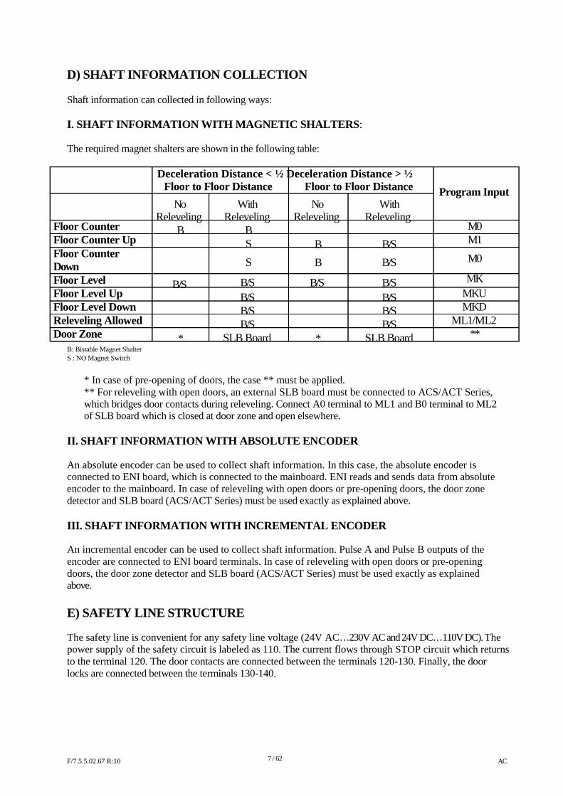
D) SHAFT INFORMATION COLLECTION Shaft information can collected in following ways: I. SHAFT INFORMATION WITH MAGNETIC SHALTERS : The required magnet shalters are shown in the following table:
Deceleration Distance < ½ Deceleration Distance > ½ Floor to Floor Distance Floor to Floor Distance Program Input
Floor Counter Floor Counter Up Floor Counter Down Floor Level Floor Level Up Floor Level Down Releveling Allowed Door Zone
No Releveling
B
B/S *
With Releveling
B S
S
B/S B/S B/S B/S
SLB Board
No Releveling
B
B
B/S *
With Releveling
B/S
B/S
B/S B/S B/S B/S
SLB Board
M0 M1
M0
MK MKU MKD
ML1/ML2 **
B: Bistable Magnet Shalter S : NO Magnet Switch
* In case of pre-opening of doors, the case ** must be applied. ** For releveling with open doors, an external SLB board must be connected to ACS/ACT Series, which bridges door contacts during releveling. Connect A0 terminal to ML1 and B0 terminal to ML2 of SLB board which is closed at door zone and open elsewhere.
II. SHAFT INFORMATION WITH ABSOLUTE ENCODER An absolute encoder can be used to collect shaft information. In this case, the absolute encoder is connected to ENI board, which is connected to the mainboard. ENI reads and sends data from absolute encoder to the mainboard. In case of releveling with open doors or pre-opening doors, the door zone detector and SLB board (ACS/ACT Series) must be used exactly as explained above. III. SHAFT INFORMATION WITH INCREMENTAL ENCODER An incremental encoder can be used to collect shaft information. Pulse A and Pulse B outputs of the encoder are connected to ENI board terminals. In case of releveling with open doors or pre-opening doors, the door zone detector and SLB board (ACS/ACT Series) must be used exactly as explained above.
E) SAFETY LINE STRUCTURE The safety line is convenient for any safety line voltage (24V AC…230V AC and 24V DC…110V DC). The power supply of the safety circuit is labeled as 110. The current flows through STOP circuit which returns to the terminal 120. The door contacts are connected between the terminals 120-130. Finally, the door locks are connected between the terminals 130-140. F/7.5.5.02.67 R:10
7 / 62
AC
Here is the explanation of terminals:
120 : It stands for stop circuit. If terminal 120 is present then it means that pit switch, shaft final switches, speed regulator, parachute and car top switch are all closed.
130 : When this terminal is present then it means the cabin door is closed. 140 : When this terminal is present, then it means that the landing doors are closed (for full
automatic systems) or the door locks are closed (for wing doors). 140 is also power supply terminal for contactor coils or hydraulic valves.
a) Contactor Coil Voltage and Safety Line Voltage Safety line voltage is allowed between the limits 24V AC…230V AC and 24V DC…110V DC. The contactors and valves which drive directly motor, inverter and hydraulic units must have the same coil voltages as the safety line voltage. If any of these components has different coil voltages than the safety line, one or more SFX boards must be connected to the circuit. You will find related connection methods in schematics. b) System with Door Bridging (Pre-Opening Doors or Releveling with Open Doors) When releveling with open doors or pre-opening doors are desired then SLB board must be add to ACS/ACT Series. This special SLB board/circuit bridges 120 - 140 through its terminals SF1 and SF2. In ACH Series, door bridging is standard. If any relay fails for any reason then the circuit blocks itself and never bridges the SF1 and SF2 terminals again which bridges the door contacts. According to the standard EN-81, this bridging circuit has to be driven by two independent door zone detectors. F/7.5.5.02.67 R:10
8 / 62
AC
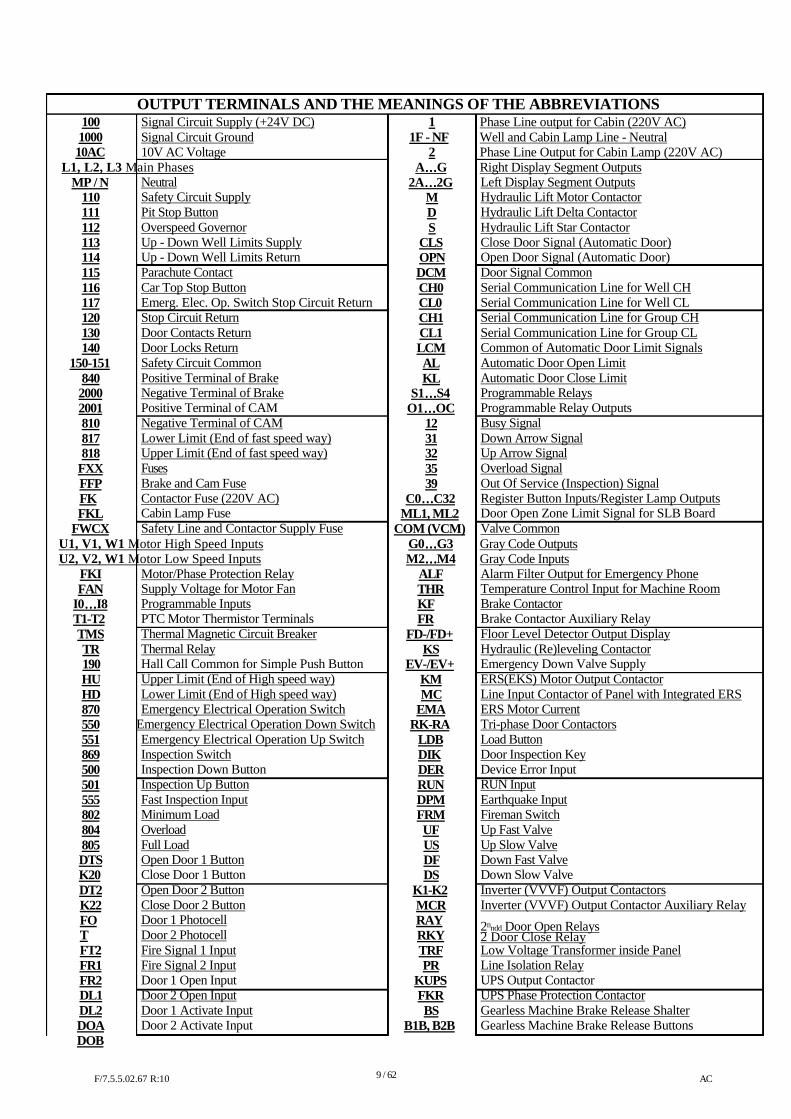
OUTPUT TERMINALS AND THE MEANINGS OF THE ABBREVIATI ONS 100 Signal Circuit Supply (+24V DC) 1 Phase Line output for Cabin (220V AC) 1000 Signal Circuit Ground 1F - NF Well and Cabin Lamp Line - Neutral 10AC 10V AC Voltage 2 Phase Line Output for Cabin Lamp (220V AC)
L1, L2, L3 Main Phases A…………G Right Display Segment Outputs MP / N
110 111 112 113 114 115 116 117 120 130 140
150-151 840 2000 2001 810 817 818
FXX FFP FK FKL
FWCX
Neutral Safety Circuit Supply Pit Stop Button Overspeed Governor Up - Down Well Limits Supply Up - Down Well Limits Return Parachute Contact Car Top Stop Button Emerg. Elec. Op. Switch Stop Circuit Return Stop Circuit Return Door Contacts Return Door Locks Return Safety Circuit Common Positive Terminal of Brake Negative Terminal of Brake Positive Terminal of CAM Negative Terminal of CAM Lower Limit (End of fast speed way) Upper Limit (End of fast speed way) Fuses Brake and Cam Fuse Contactor Fuse (220V AC) Cabin Lamp Fuse Safety Line and Contactor Supply Fuse
2A…………2G M D S
CLS OPN DCM CH0 CL0 CH1 CL1 LCM AL KL
S1…………S4 O1…………OC
12 31 32 35 39
C0…………C32 ML1, ML2
COM (VCM)
Left Display Segment Outputs Hydraulic Lift Motor Contactor Hydraulic Lift Delta Contactor Hydraulic Lift Star Contactor Close Door Signal (Automatic Door) Open Door Signal (Automatic Door) Door Signal Common Serial Communication Line for Well CH Serial Communication Line for Well CL Serial Communication Line for Group CH Serial Communication Line for Group CL Common of Automatic Door Limit Signals Automatic Door Open Limit Automatic Door Close Limit Programmable Relays Programmable Relay Outputs Busy Signal Down Arrow Signal Up Arrow Signal Overload Signal Out Of Service (Inspection) Signal Register Button Inputs/Register Lamp Outputs Door Open Zone Limit Signal for SLB Board Valve Common
U1, V1, W1 Motor High Speed Inputs G0…………G3 Gray Code Outputs U2, V2, W1 Motor Low Speed Inputs M2…………M4 Gray Code Inputs
FKI FAN
I0…………I8 T1-T2 TMS TR 190 HU HD 870 550 551 869 500 501 555 802 804 805 DTS K20 DT2 K22 FOT FT2 FR1 FR2 DL1 DL2 DOA DOB
Motor/Phase Protection Relay Supply Voltage for Motor Fan Programmable Inputs PTC Motor Thermistor Terminals Thermal Magnetic Circuit Breaker Thermal Relay Hall Call Common for Simple Push Button Upper Limit (End of High speed way) Lower Limit (End of High speed way) Emergency Electrical Operation Switch
Emergency Electrical Operation Down Switch Emergency Electrical Operation Up Switch Inspection Switch Inspection Down Button Inspection Up Button Fast Inspection Input Minimum Load Overload Full Load Open Door 1 Button Close Door 1 Button Open Door 2 Button Close Door 2 Button Door 1 Photocell Door 2 Photocell Fire Signal 1 Input Fire Signal 2 Input Door 1 Open Input Door 2 Open Input Door 1 Activate Input Door 2 Activate Input
ALF THR KF FR
FD-/FD+ KS
EV-/EV+ KM MC
EMA RK-RA
LDB DIK DER RUN DPM FRM UF US DF DS
K1-K2 MCR RAY RKY TRF PR
KUPS FKR BS
B1B, B2B
Alarm Filter Output for Emergency Phone Temperature Control Input for Machine Room Brake Contactor Brake Contactor Auxiliary Relay Floor Level Detector Output Display Hydraulic (Re)leveling Contactor Emergency Down Valve Supply ERS(EKS) Motor Output Contactor Line Input Contactor of Panel with Integrated ERS ERS Motor Current Tri-phase Door Contactors Load Button Door Inspection Key Device Error Input RUN Input Earthquake Input Fireman Switch Up Fast Valve Up Slow Valve Down Fast Valve Down Slow Valve Inverter (VVVF) Output Contactors Inverter (VVVF) Output Contactor Auxiliary Relay 2nndd Door Open Relays 2 Door Close Relay Low Voltage Transformer inside Panel Line Isolation Relay UPS Output Contactor UPS Phase Protection Contactor Gearless Machine Brake Release Shalter Gearless Machine Brake Release Buttons
F/7.5.5.02.67 R:10
9 / 62
AC
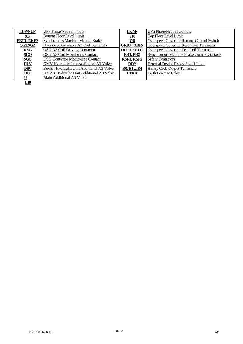
LUP/NUP 917
EKF1, EKF2 SG1,SG2
KSG SGO SGC DLV DSV HDU L10
UPS Phase/Neutral Inputs Bottom Floor Level Limit Synchronous Machine Manual Brake Overspeed Governor A3 Coil Terminals OSG A3 Coil Driving Contactor OSG A3 Coil Monitoring Contact KSG Contactor Monitoring Contact GMV Hydraulic Unit Additional A3 Valve Bucher Hydraulic Unit Additional A3 Valve OMAR Hydraulic Unit Additional A3 Valve Blain Additional A3 Valve
LP/NP 918 OR
ORR+, ORR- ORT+, ORT-
BR1, BR2 KSF1, KSF2
RDY B0, B1…………B4
FTKR
UPS Phase/Neutral Outputs Top Floor Level Limit Overspeed Governor Remote Control Switch Overspeed Governor Reset Coil Terminals Overspeed Governor Test Coil Terminals Synchronous Machine Brake Control Contacts Safety Contactors External Device Ready Signal Input Binary Code Output Terminals Earth Leakage Relay
F/7.5.5.02.67 R:10
10 / 62
AC
CHAPTER 1:
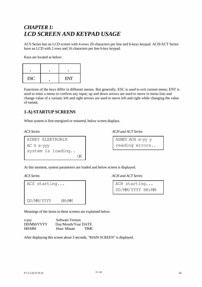
LCD SCREEN AND KEYPAD USAGE ACS Series has an LCD screen with 4-rows 20-characters per line and 6-keys keypad. ACH/ACT Series have an LCD with 2 rows and 16 characters per line 6-key keypad. Keys are located as below: � � �
ESC � ENT
Functions of the keys differ in different menus. But generally, ESC is used to exit current menu; ENT is used to enter a menu or confirm any input; up and down arrows are used to move in menu lists and change value of a variant; left and right arrows are used to move left and right while changing the value of variant. 1-A) STARTUP SCREENS When system is first energized or restarted, below screen displays. ACS Series
AYBEY ELEKTRONiK
AC S x-yyy system is loading..
OK
ACH and ACT Series
AYBEY ACH x-yy y reading errors..
At this moment, system parameters are loaded and below screen is displayed. ACS Series ACH and ACT Series
ACS starting... ACH starting...
DD/MM/YYYY HH:MM
DD/MM/YYYY HH:MM
Meanings of the items in these screens are explained below. x-yyy Software Version DD/MM/YYYY Day/Month/Year DATE HH:MM Hour: Minute TIME After displaying this screen about 3 seconds, "MAIN SCREEN" is displayed. F/7.5.5.02.67 R:10
11 / 62
AC
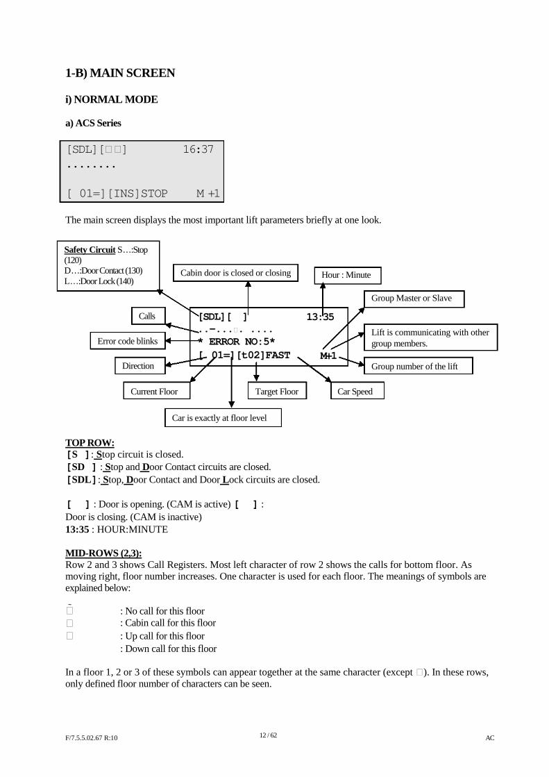
1-B) MAIN SCREEN i) NORMAL MODE a) ACS Series [SDL][ ] 16:37 ........
[ 01=][INS]STOP M +1
The main screen displays the most important lift parameters briefly at one look. Safety Circuit S…:Stop (120) D…:Door Contact (130) L…:Door Lock (140)
Cabin door is closed or closing Hour : Minute
Calls
Error code blinks
Direction
[SDL][��] ..-.... .... * ERROR NO:5* [�01=][t02]FAST
13:35
M+1
Group Master or Slave Lift is communicating with other group members. Group number of the lift
Current Floor Target Floor Car Speed
Car is exactly at floor level
TOP ROW: [S ]: Stop circuit is closed. [SD ] : Stop and Door Contact circuits are closed. [SDL]: Stop, Door Contact and Door Lock circuits are closed. [��] : Door is opening. (CAM is active) [��] : Door is closing. (CAM is inactive) 13:35 : HOUR:MINUTE MID-ROWS (2,3): Row 2 and 3 shows Call Registers. Most left character of row 2 shows the calls for bottom floor. As moving right, floor number increases. One character is used for each floor. The meanings of symbols are explained below:
: No call for this floor : Cabin call for this floor : Up call for this floor : Down call for this floor
In a floor 1, 2 or 3 of these symbols can appear together at the same character (except ). In these rows, only defined floor number of characters can be seen. F/7.5.5.02.67 R:10
12 / 62
AC
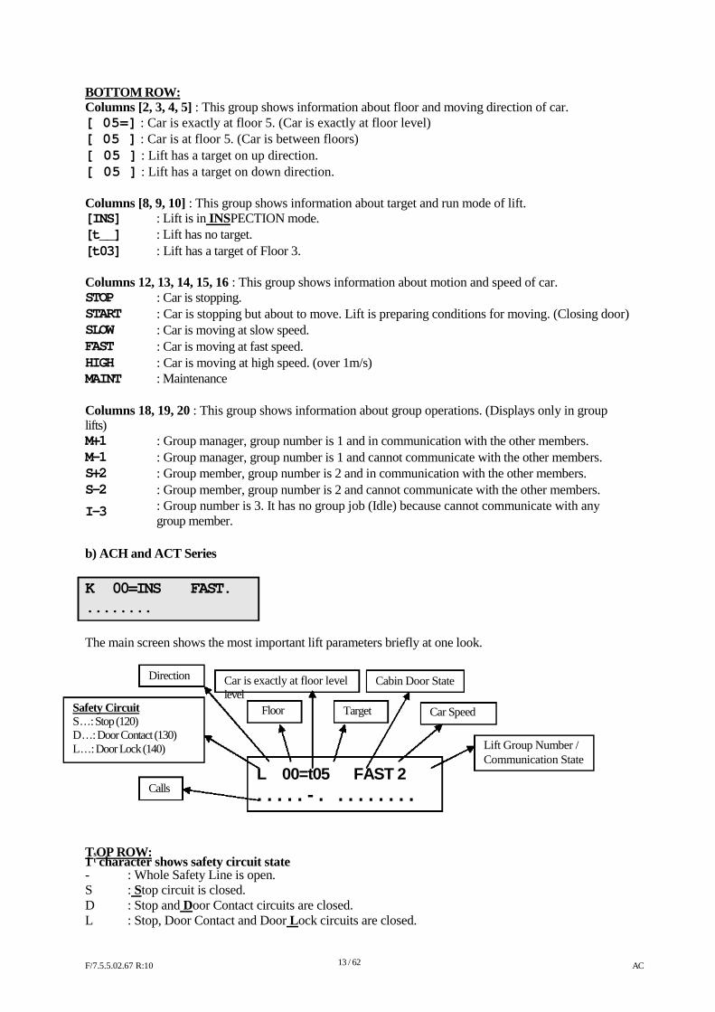
BOTTOM ROW: Columns [2, 3, 4, 5] : This group shows information about floor and moving direction of car. [ 05=] : Car is exactly at floor 5. (Car is exactly at floor level) [ 05 ] : Car is at floor 5. (Car is between floors) [�05 ] : Lift has a target on up direction. [�05 ] : Lift has a target on down direction. Columns [8, 9, 10] : This group shows information about target and run mode of lift. [INS] : Lift is in INSPECTION mode. [t__] : Lift has no target. [t03] : Lift has a target of Floor 3. Columns 12, 13, 14, 15, 16 : This group shows information about motion and speed of car. STOP START SLOW FAST HIGH MAINT
: Car is stopping. : Car is stopping but about to move. Lift is preparing conditions for moving. (Closing door) : Car is moving at slow speed. : Car is moving at fast speed. : Car is moving at high speed. (over 1m/s) : Maintenance
Columns 18, 19, 20 : This group shows information about group operations. (Displays only in group lifts) M+1 M-1 S+2 S-2
I-3
: Group manager, group number is 1 and in communication with the other members. : Group manager, group number is 1 and cannot communicate with the other members. : Group member, group number is 2 and in communication with the other members. : Group member, group number is 2 and cannot communicate with the other members. : Group number is 3. It has no group job (Idle) because cannot communicate with any group member.
b) ACH and ACT Series K� 00=INS � � FAST. ........
The main screen shows the most important lift parameters briefly at one look.
Direction
Car is exactly at floor level level
Cabin Door State
Safety Circuit S…: Stop (120) D…: Door Contact (130) L…: Door Lock (140)
Floor Target Car Speed
Lift Group Number / Communication State
Calls
L� 00=t05��FAST 2
. . . . . - .�. . . . . . . .
TsOP ROW: 1 t character shows safety circuit state - : Whole Safety Line is open. S : Stop circuit is closed. D : Stop and Door Contact circuits are closed. L : Stop, Door Contact and Door Lock circuits are closed. F/7.5.5.02.67 R:10
13 / 62
AC
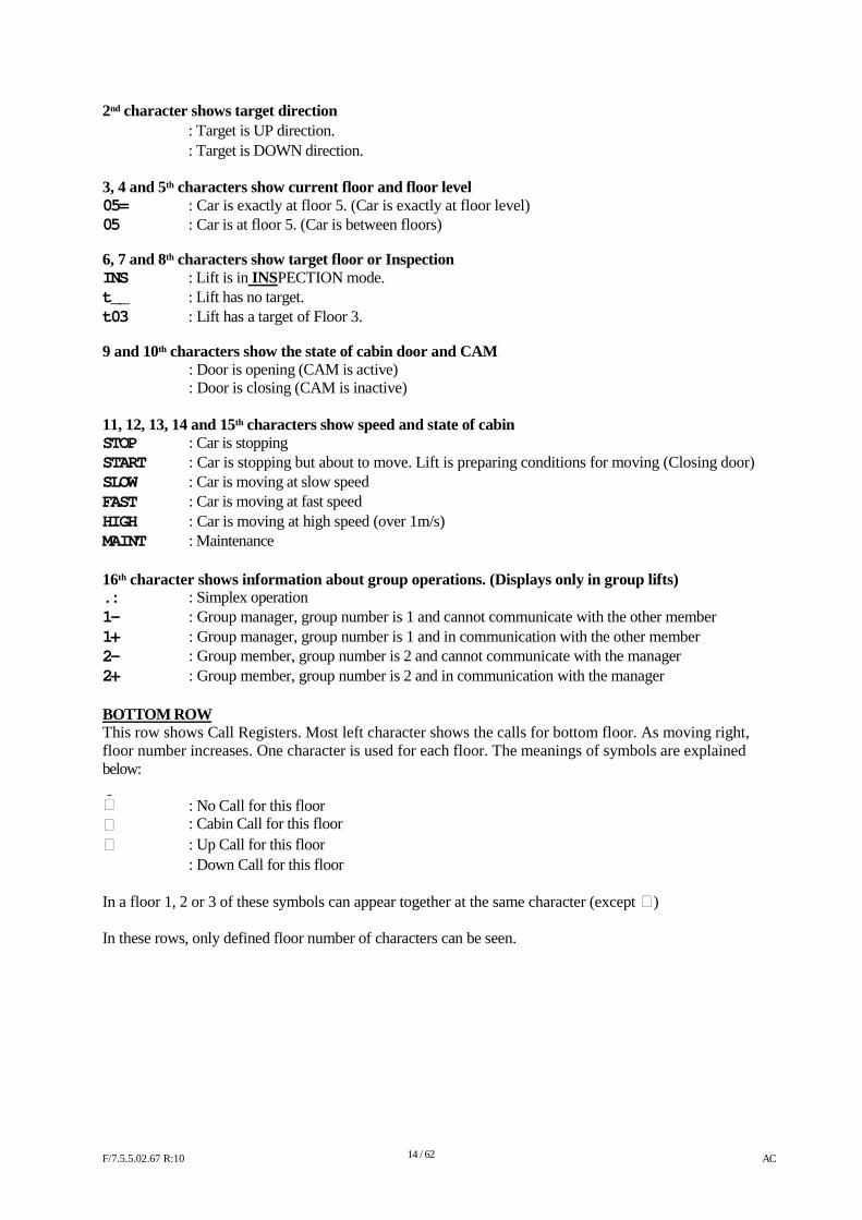
2nd character shows target direction � : Target is UP direction. � : Target is DOWN direction. 3, 4 and 5th characters show current floor and floor level 05= : Car is exactly at floor 5. (Car is exactly at floor level) 05 : Car is at floor 5. (Car is between floors) 6, 7 and 8th characters show target floor or Inspection INS : Lift is in INSPECTION mode. t__ : Lift has no target. t03 : Lift has a target of Floor 3. 9 and 10th characters show the state of cabin door and CAM �� ��
: Door is opening (CAM is active) : Door is closing (CAM is inactive)
11, 12, 13, 14 and 15th characters show speed and state of cabin STOP START SLOW FAST HIGH MAINT
: Car is stopping : Car is stopping but about to move. Lift is preparing conditions for moving (Closing door) : Car is moving at slow speed : Car is moving at fast speed : Car is moving at high speed (over 1m/s) : Maintenance
16th character shows information about group operations. (Displays only in group lifts) .: 1- 1+ 2- 2+
: Simplex operation : Group manager, group number is 1 and cannot communicate with the other member : Group manager, group number is 1 and in communication with the other member : Group member, group number is 2 and cannot communicate with the manager : Group member, group number is 2 and in communication with the manager
BOTTOM ROW This row shows Call Registers. Most left character shows the calls for bottom floor. As moving right, floor number increases. One character is used for each floor. The meanings of symbols are explained below:
: No Call for this floor : Cabin Call for this floor : Up Call for this floor : Down Call for this floor
In a floor 1, 2 or 3 of these symbols can appear together at the same character (except ) In these rows, only defined floor number of characters can be seen. F/7.5.5.02.67 R:10
14 / 62
AC
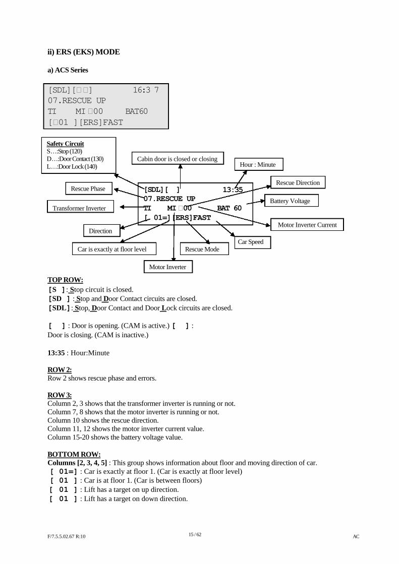
ii) ERS (EKS) MODE a) ACS Series [SDL][ ] 16:3 7 07.RESCUE UP TI MI 00 BAT60 [01 ][ERS]FAST
Safety Circuit S…:Stop (120) D…:Door Contact (130) L…:Door Lock (140)
Cabin door is closed or closing
Hour : Minute
Rescue Phase
[SDL][��] 07.RESCUE UP
13:35
Rescue Direction
Battery Voltage
Transformer Inverter TI MI 00 BAT 60 [�01=][ERS]FAST
Motor Inverter Current Direction
Car Speed Car is exactly at floor level Rescue Mode
Motor Inverter
TOP ROW: [S ]: Stop circuit is closed. [SD ] : Stop and Door Contact circuits are closed. [SDL]: Stop, Door Contact and Door Lock circuits are closed. [��] : Door is opening. (CAM is active.) [��] : Door is closing. (CAM is inactive.) 13:35 : Hour:Minute ROW 2: Row 2 shows rescue phase and errors. ROW 3: Column 2, 3 shows that the transformer inverter is running or not. Column 7, 8 shows that the motor inverter is running or not. Column 10 shows the rescue direction. Column 11, 12 shows the motor inverter current value. Column 15-20 shows the battery voltage value. BOTTOM ROW: Columns [2, 3, 4, 5] : This group shows information about floor and moving direction of car. [ 01=] : Car is exactly at floor 1. (Car is exactly at floor level) [ 01 ] : Car is at floor 1. (Car is between floors) [�01 ] : Lift has a target on up direction. [�01 ] : Lift has a target on down direction. F/7.5.5.02.67 R:10
15 / 62
AC
Columns [8, 9, 10] : This group shows information about target and run mode of lift. [ERS] : Lift is in Rescue mode. Columns 12, 13, 14, 15, 16 : This group shows information about motion and speed of car. STOP : Car is stopping. START : Car is stopping and preparing conditions for moving. (Closing door) FAST : Car is moving at fast speed.
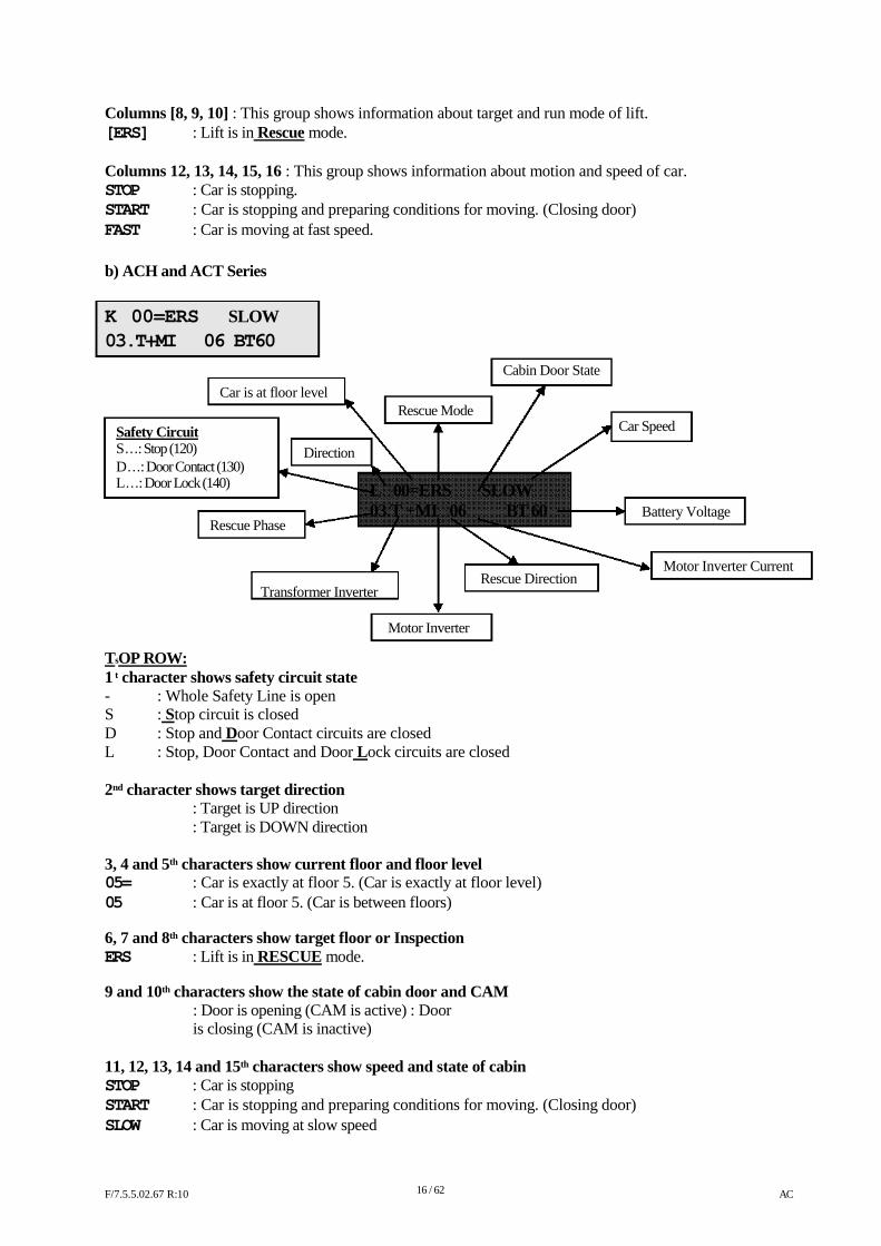
b) ACH and ACT Series
K�00=ERS� �SLOW 03.T+MI � 06 BT60
Safety Circuit S…: Stop (120)
Car is at floor level
Direction
Rescue Mode
Cabin Door State Car Speed
D…: Door Contact (130) L…: Door Lock (140)
L00=ERS� �SLOW 03.T +MI06 BT 60 Battery Voltage
Rescue Phase
Motor Inverter Current
Rescue Direction
TsOP ROW:
Transformer Inverter Motor Inverter
1 t character shows safety circuit state - : Whole Safety Line is open S : Stop circuit is closed D : Stop and Door Contact circuits are closed L : Stop, Door Contact and Door Lock circuits are closed 2nd character shows target direction � : Target is UP direction � : Target is DOWN direction 3, 4 and 5th characters show current floor and floor level 05= : Car is exactly at floor 5. (Car is exactly at floor level) 05 : Car is at floor 5. (Car is between floors) 6, 7 and 8th characters show target floor or Inspection ERS : Lift is in RESCUE mode. 9 and 10th characters show the state of cabin door and CAM �� ��
: Door is opening (CAM is active) : Door is closing (CAM is inactive)
11, 12, 13, 14 and 15th characters show speed and state of cabin STOP : Car is stopping START : Car is stopping and preparing conditions for moving. (Closing door) SLOW : Car is moving at slow speed F/7.5.5.02.67 R:10
16 / 62
AC
BOTTOM dROW 1, 2 and 3r characters show the rescue phase 03. : Rescue Phase 3 4 and 5th characters show the state of transformer inverter T+ : Transformer inverter is on T- : Transformer inverter is off 6, 7, 8, 9 and 10th characters show the motor inverter direction and current MI�06 : Motor inverter direction is up and current is 6 A 13, 14, 15 and 16th characters show the battery voltage BT60 : Battery voltage is 60V
1-C) MONITORING OF INPUTS
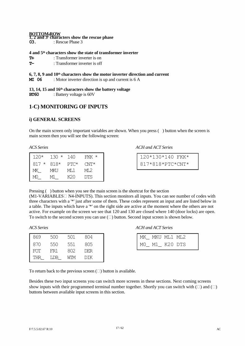
i) GENERAL SCREENS On the main screen only important variables are shown. When you press (�) button when the screen is main screen then you will see the following screen:
ACS Series ACH and ACT Series
120* 130 * 140 FKK * 120*130*140 FKK*
817 * 818* PTC* CNT* 817*818*PTC*CNT* MK_ MKU ML1 ML2 M0_ M1_ K20 DTS
Pressing (�) button when you see the main screen is the shortcut for the section (M1-VARIABLES N4-INPUTS). This section monitors all inputs. You can see number of codes with three characters with a '*' just after some of them. These codes represent an input and are listed below in a table. The inputs which have a '*' on the right side are active at the moment where the others are not active. For example on the screen we see that 120 and 130 are closed where 140 (door locks) are open. To switch to the second screen you can use () button. Second input screen is shown below. ACS Series ACH and ACT Series
869 500 501 804 MK_ MKU ML1 ML2
870 550 551 805 M0_ M1_ K20 DTS FOT FR1 802 DER THR_ LDB_ WTM DIK
To return back to the previous screen () button is available. Besides these two input screens you can switch more screens in these sections. Next coming screens show inputs with their programmed terminal number together. Shortly you can switch with () and () buttons between available input screens in this section. F/7.5.5.02.67 R:10
17 / 62
AC
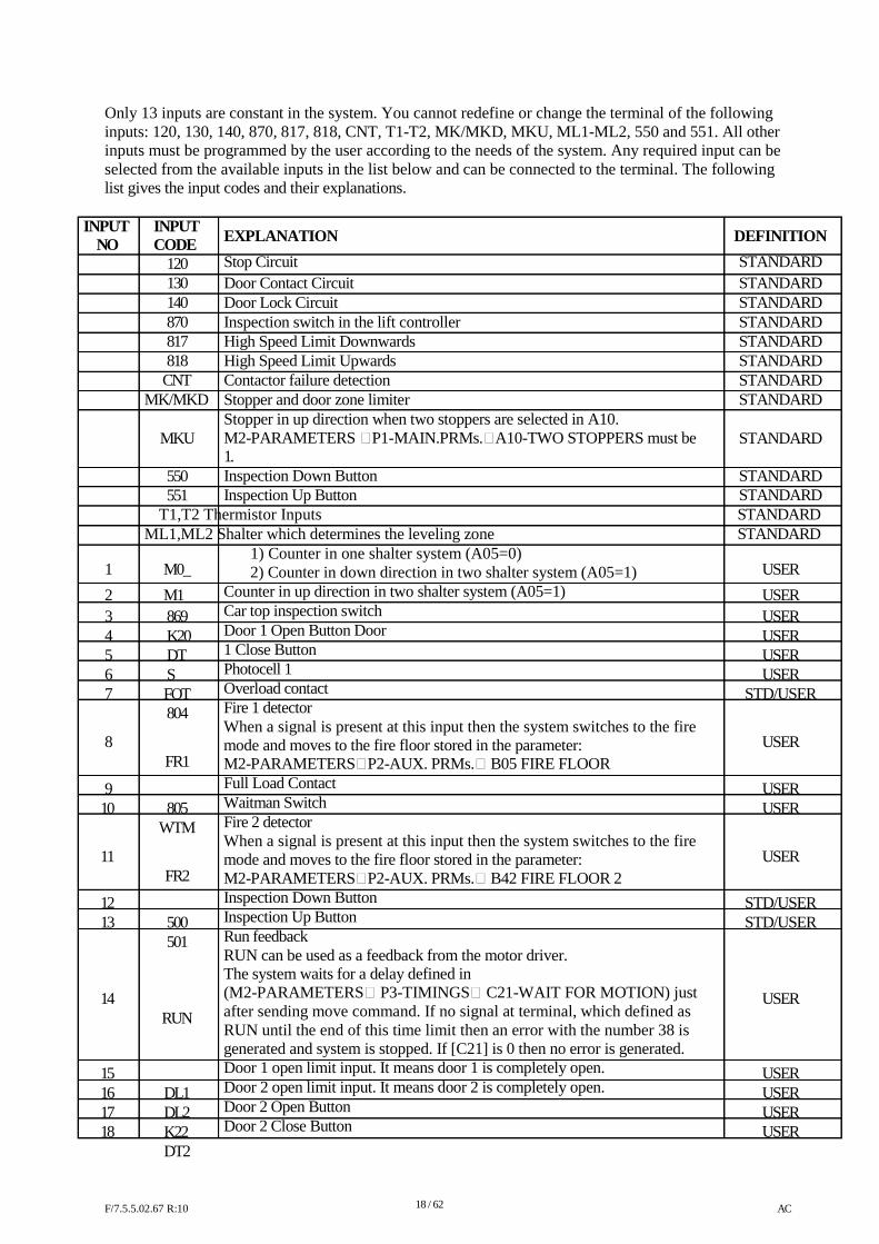
Only 13 inputs are constant in the system. You cannot redefine or change the terminal of the following inputs: 120, 130, 140, 870, 817, 818, CNT, T1-T2, MK/MKD, MKU, ML1-ML2, 550 and 551. All other inputs must be programmed by the user according to the needs of the system. Any required input can be selected from the available inputs in the list below and can be connected to the terminal. The following list gives the input codes and their explanations.
INPUT NO
INPUT CODE
120 130 140 870 817 818 CNT
MK/MKD
MKU 550 551
EXPLANATION
Stop Circuit Door Contact Circuit Door Lock Circuit Inspection switch in the lift controller High Speed Limit Downwards High Speed Limit Upwards Contactor failure detection Stopper and door zone limiter Stopper in up direction when two stoppers are selected in A10. M2-PARAMETERS P1-MAIN.PRMs.A10-TWO STOPPERS must be 1. Inspection Down Button Inspection Up Button
DEFINITION
STANDARD STANDARD STANDARD STANDARD STANDARD STANDARD STANDARD STANDARD STANDARD STANDARD STANDARD
T1,T2 Thermistor Inputs STANDARD ML1,ML2 Shalter which determines the leveling zone STANDARD
1) Counter in one shalter system (A05=0) 1
2 345 6 7 8
9 10 11
12 13
14 15 16 17 18
M0_
M1_ 869 K20 DTS FOT 804 FR1
805
WTM FR2
500 501
RUN DL1 DL2 K22 DT2
2) Counter in down direction in two shalter system (A05=1) Counter in up direction in two shalter system (A05=1) Car top inspection switch Door 1 Open Button Door 1 Close Button Photocell 1 Overload contact Fire 1 detector When a signal is present at this input then the system switches to the fire mode and moves to the fire floor stored in the parameter: M2-PARAMETERSP2-AUX. PRMs. B05 FIRE FLOOR Full Load Contact Waitman Switch Fire 2 detector When a signal is present at this input then the system switches to the fire mode and moves to the fire floor stored in the parameter: M2-PARAMETERSP2-AUX. PRMs. B42 FIRE FLOOR 2 Inspection Down Button Inspection Up Button Run feedback RUN can be used as a feedback from the motor driver. The system waits for a delay defined in (M2-PARAMETERS P3-TIMINGS C21-WAIT FOR MOTION) just after sending move command. If no signal at terminal, which defined as RUN until the end of this time limit then an error with the number 38 is generated and system is stopped. If [C21] is 0 then no error is generated. Door 1 open limit input. It means door 1 is completely open. Door 2 open limit input. It means door 2 is completely open. Door 2 Open Button Door 2 Close Button
USER
USER USER USER USER USER
STD/USER
USER
USER USER USER
STD/USER STD/USER
USER USER USER USER USER
F/7.5.5.02.67 R:10
18 / 62
AC
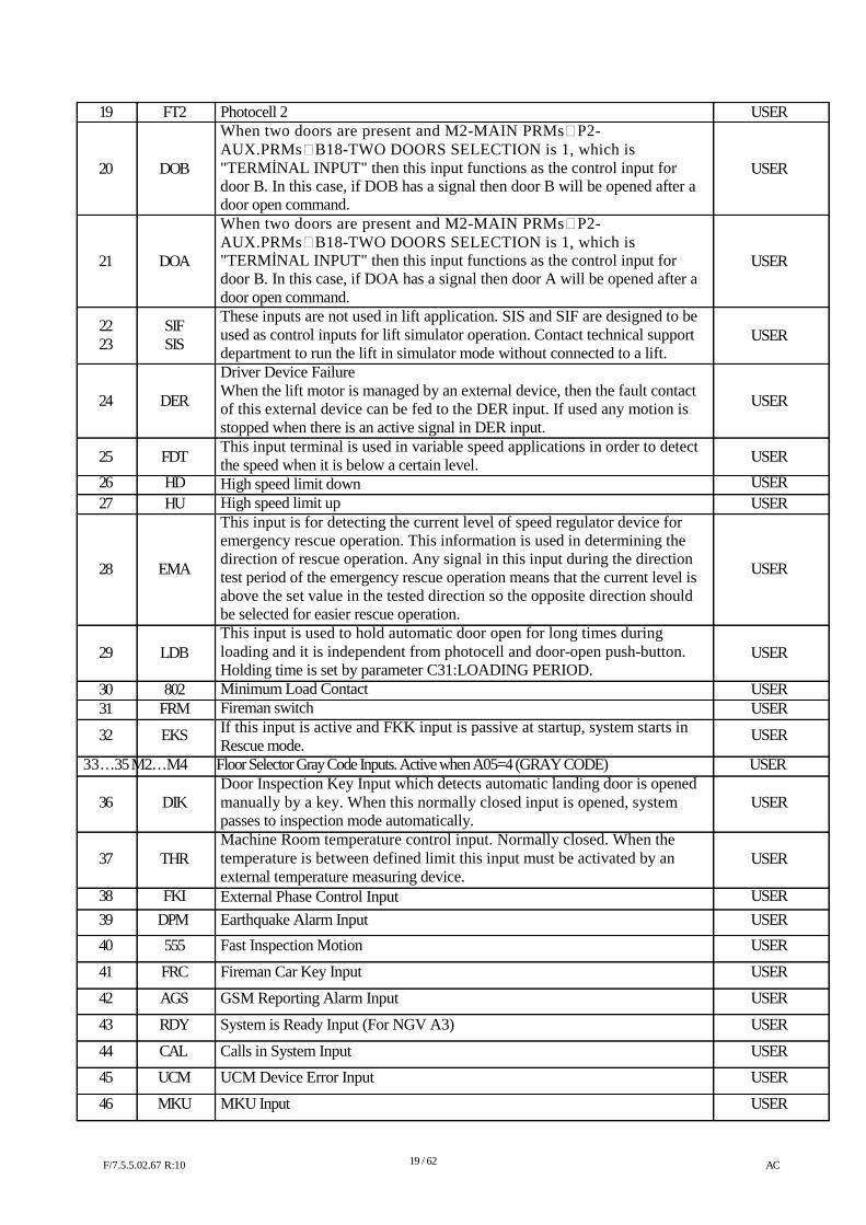
19 20
21 22 23 24 25
26 27 28 29 30 31
32
FT2 DOB
DOA SIF SIS
DER FDT
HD HU
EMA LDB 802
FRM
EKS
Photocell 2 When two doors are present and M2-MAIN PRMsP2- AUX.PRMsB18-TWO DOORS SELECTION is 1, which is "TERMİNAL INPUT" then this input functions as the control input for door B. In this case, if DOB has a signal then door B will be opened after a door open command. When two doors are present and M2-MAIN PRMsP2- AUX.PRMsB18-TWO DOORS SELECTION is 1, which is "TERMİNAL INPUT" then this input functions as the control input for door B. In this case, if DOA has a signal then door A will be opened after a door open command. These inputs are not used in lift application. SIS and SIF are designed to be used as control inputs for lift simulator operation. Contact technical support department to run the lift in simulator mode without connected to a lift. Driver Device Failure When the lift motor is managed by an external device, then the fault contact of this external device can be fed to the DER input. If used any motion is stopped when there is an active signal in DER input. This input terminal is used in variable speed applications in order to detect the speed when it is below a certain level. High speed limit down High speed limit up This input is for detecting the current level of speed regulator device for emergency rescue operation. This information is used in determining the direction of rescue operation. Any signal in this input during the direction test period of the emergency rescue operation means that the current level is above the set value in the tested direction so the opposite direction should be selected for easier rescue operation. This input is used to hold automatic door open for long times during loading and it is independent from photocell and door-open push-button. Holding time is set by parameter C31:LOADING PERIOD. Minimum Load Contact Fireman switch If this input is active and FKK input is passive at startup, system starts in Rescue mode.
USER USER
USER
USER USER USER
USER USER USER USER USER USER
USER
33…35 M2…M4 Floor Selector Gray Code Inputs. Active when A05=4 (GRAY CODE) USER Door Inspection Key Input which detects automatic landing door is opened
36 37
38
39
40
41
42
43
44
45
46
DIK THR
FKI DPM
555
FRC
AGS
RDY
CAL
UCM
MKU
manually by a key. When this normally closed input is opened, system passes to inspection mode automatically. Machine Room temperature control input. Normally closed. When the temperature is between defined limit this input must be activated by an external temperature measuring device. External Phase Control Input Earthquake Alarm Input
Fast Inspection Motion
Fireman Car Key Input
GSM Reporting Alarm Input
System is Ready Input (For NGV A3)
Calls in System Input
UCM Device Error Input
MKU Input
USER USER
USER
USER
USER
USER
USER
USER
USER
USER
USER
F/7.5.5.02.67 R:10
19 / 62
AC
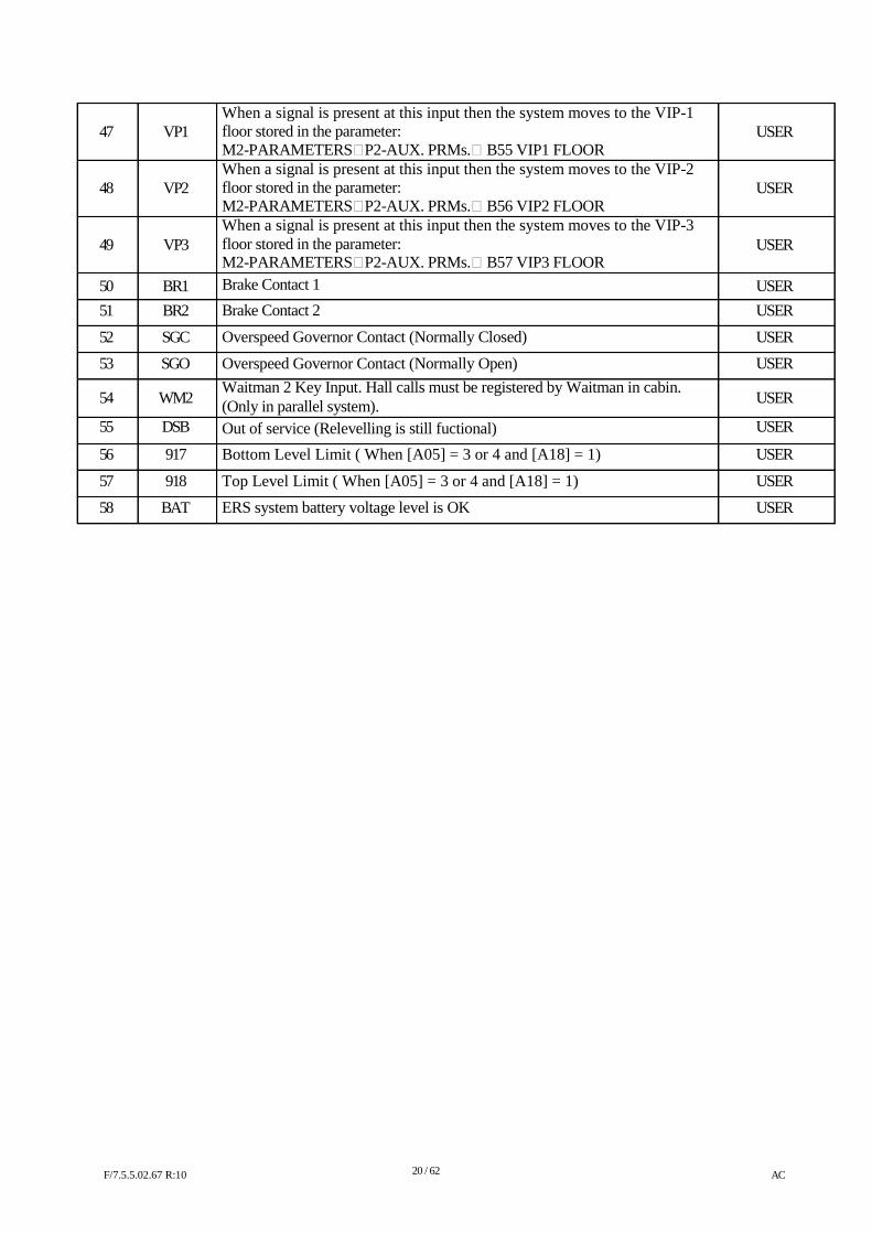
47 48 49
50 51
52
53 54
55
56
57
58
VP1 VP2 VP3
BR1 BR2
SGC
SGO WM2
DSB
917
918
BAT
When a signal is present at this input then the system moves to the VIP-1 floor stored in the parameter: M2-PARAMETERSP2-AUX. PRMs. B55 VIP1 FLOOR When a signal is present at this input then the system moves to the VIP-2 floor stored in the parameter: M2-PARAMETERSP2-AUX. PRMs. B56 VIP2 FLOOR When a signal is present at this input then the system moves to the VIP-3 floor stored in the parameter: M2-PARAMETERSP2-AUX. PRMs. B57 VIP3 FLOOR Brake Contact 1
Brake Contact 2
Overspeed Governor Contact (Normally Closed)
Overspeed Governor Contact (Normally Open) Waitman 2 Key Input. Hall calls must be registered by Waitman in cabin. (Only in parallel system). Out of service (Relevelling is still fuctional)
Bottom Level Limit ( When [A05] = 3 or 4 and [A18] = 1)
Top Level Limit ( When [A05] = 3 or 4 and [A18] = 1)
ERS system battery voltage level is OK
USER USER USER
USER USER
USER
USER USER
USER
USER
USER
USER F/7.5.5.02.67 R:10
20 / 62
AC
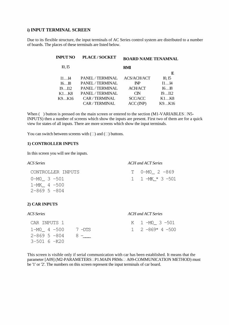
i) INPUT TERMINAL SCREEN Due to its flexible structure, the input terminals of AC Series control system are distributed to a number of boards. The places of these terminals are listed below.
INPUT NO I0, I5
PLACE / SOCKET
BOARD NAME TENAMNAL
RMI E
I1…I4 I6…I8 I9…I12 K1…K8 K9…K16
PANEL / TERMINAL PANEL / TERMINAL PANEL / TERMINAL PANEL / TERMINAL
CAR / TERMINAL CAR / TERMINAL
ACS/ACH/ACT INP
ACH/ACT CIN
SCC/ACC ACC (INP)
I0, I5 I1…I4 I6…I8 I9…I12 K1…K8 K9…K16
When (�) button is pressed on the main screen or entered to the section (M1-VARIABLESN5- INPUTS) then a number of screens which show the inputs are present. First two of them are for a quick view for states of all inputs. There are more screens which show the input terminals. You can switch between screens with () and () buttons. 1) CONTROLLER INPUTS In this screen you will see the inputs. ACS Series ACH and ACT Series
CONTROLLER INPUTS T 0-M0_ 2 -869
0-M0_ 3 -501 1 1 -MK_* 3 -501 1-MK_ 4 -500 2-869 5 -804
2) CAR INPUTS ACS Series ACH and ACT Series
CAR INPUTS 1 K 1 -M0_ 3 -501 1-M0_ 4 -500 7 -DTS 1 2 -869* 4 -500 2-869 5 -804 8 -___ 3-501 6 -K20
This screen is visible only if serial communication with car has been established. It means that the parameter [A09] (M2-PARAMETERSP1.MAIN PRMs A09-COMMUNICATION METHOD) must be '1' or '2'. The numbers on this screen represent the input terminals of car board.
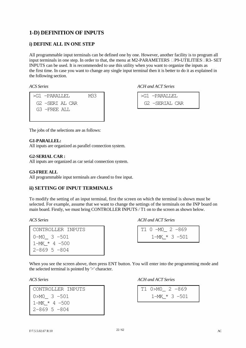
1-D) DEFINITION OF INPUTS i) DEFINE ALL IN ONE STEP All programmable input terminals can be defined one by one. However, another facility is to program all input terminals in one step. In order to that, the menu at M2-PARAMETERS P9-UTILITIESR3- SET INPUTS can be used. It is recommended to use this utility when you want to organize the inputs as the first time. In case you want to change any single input terminal then it is better to do it as explained in the following section. ACS Series ACH and ACT Series
>G1 -PARALLEL M33 >G1 -PARALLEL
G2 -SERI AL CAR G2 -SERIAL CAR G3 -FREE ALL
The jobs of the selections are as follows: G1-PARALLEL: All inputs are organized as parallel connection system. G2-SERIAL CAR : All inputs are organized as car serial connection system. G3-FREE ALL All programmable input terminals are cleared to free input. ii) SETTING OF INPUT TERMINALS To modify the setting of an input terminal, first the screen on which the terminal is shown must be selected. For example, assume that we want to change the settings of the terminals on the INP board on main board. Firstly, we must bring CONTROLLER INPUTS / T1 on to the screen as shown below. ACS Series
CONTROLLER INPUTS
0-M0_ 3 -501 1-MK_* 4 -500 2-869 5 -804
ACH and ACT Series
T1 0 -M0_ 2 -869
1-MK_* 3 -501
When you see the screen above, then press ENT button. You will enter into the programming mode and the selected terminal is pointed by '>' character. ACS Series
CONTROLLER INPUTS
0>M0_ 3 -501 1-MK_* 4 -500 2-869 5 -804
ACH and ACT Series
T1 0>M0_ 2 -869
1-MK_* 3 -501
F/7.5.5.02.67 R:10
22 / 62
AC
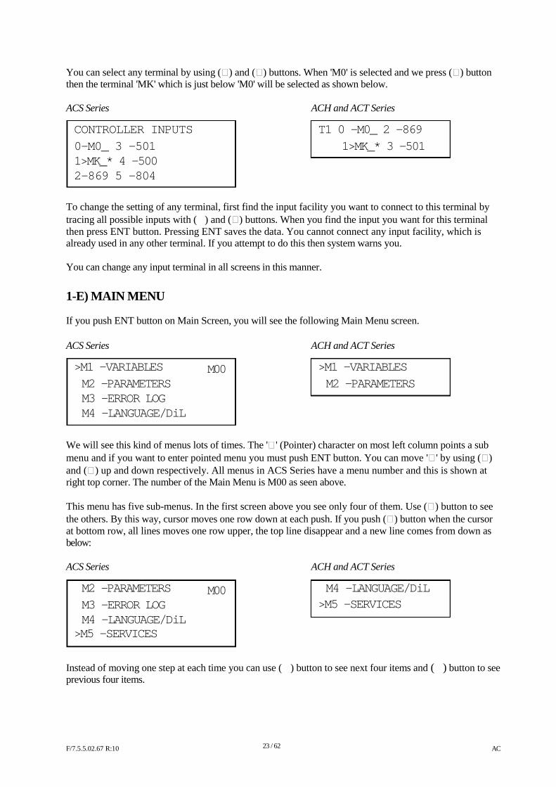
You can select any terminal by using () and () buttons. When 'M0' is selected and we press () button then the terminal 'MK' which is just below 'M0' will be selected as shown below. ACS Series
CONTROLLER INPUTS
0-M0_ 3 -501 1>MK_* 4 -500 2-869 5 -804
ACH and ACT Series
T1 0 -M0_ 2 -869
1>MK_* 3 -501
To change the setting of any terminal, first find the input facility you want to connect to this terminal by tracing all possible inputs with (�) and () buttons. When you find the input you want for this terminal then press ENT button. Pressing ENT saves the data. You cannot connect any input facility, which is already used in any other terminal. If you attempt to do this then system warns you. You can change any input terminal in all screens in this manner.
1-E) MAIN MENU If you push ENT button on Main Screen, you will see the following Main Menu screen. ACS Series
>M1 -VARIABLES M2 -PARAMETERS M3 -ERROR LOG M4 -LANGUAGE/DiL
M00
ACH and ACT Series
>M1 -VARIABLES M2 -PARAMETERS
We will see this kind of menus lots of times. The '' (Pointer) character on most left column points a sub menu and if you want to enter pointed menu you must push ENT button. You can move '' by using () and () up and down respectively. All menus in ACS Series have a menu number and this is shown at right top corner. The number of the Main Menu is M00 as seen above. This menu has five sub-menus. In the first screen above you see only four of them. Use () button to see the others. By this way, cursor moves one row down at each push. If you push () button when the cursor at bottom row, all lines moves one row upper, the top line disappear and a new line comes from down as below: ACS Series
M2 -PARAMETERS M3 -ERROR LOG M4 -LANGUAGE/DiL
>M5 -SERVICES
M00
ACH and ACT Series
M4 -LANGUAGE/DiL
>M5 -SERVICES
Instead of moving one step at each time you can use (�) button to see next four items and (�) button to see previous four items.
F/7.5.5.02.67 R:10
23 / 62
AC
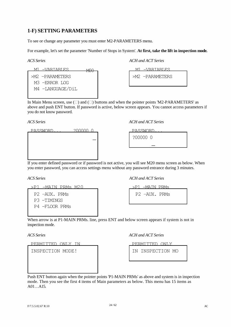
1-F) SETTING PARAMETERS To see or change any parameter you must enter M2-PARAMETERS menu. For example, let's set the parameter 'Number of Stops in System'. At first, take the lift in inspection mode. ACS Series
M1 -VARIABLES >M2 -PARAMETERS M3 -ERROR LOG M4 -LANGUAGE/DiL
M00
ACH and ACT Series
M1 -VARIABLES >M2 -PARAMETERS
In Main Menu screen, use () and () buttons and when the pointer points 'M2-PARAMETERS' as above and push ENT button. If password is active, below screen appears. You cannot access parameters if you do not know password. ACS Series ACH and ACT Series
PASSWORD... ?00000 0 PASSWORD...
?00000 0
If you enter defined password or if password is not active, you will see M20 menu screen as below. When you enter password, you can access settings menu without any password entrance during 3 minutes. ACS Series
>P1 -MAIN PRMs M20
P2 -AUX. PRMs P3 -TIMINGS P4 -FLOOR PRMs
ACH and ACT Series
>P1 -MAIN PRMs
P2 -AUX. PRMs
When arrow is at P1-MAIN PRMs. line, press ENT and below screen appears if system is not in inspection mode. ACS Series ACH and ACT Series
PERMITTED ONLY IN PERMITTED ONLY
INSPECTION MODE! IN INSPECTION MO
Push ENT button again when the pointer points 'P1-MAIN PRMs' as above and system is in inspection mode. Then you see the first 4 items of Main parameters as below. This menu has 15 items as A01…A15.
F/7.5.5.02.67 R:10
24 / 62
AC
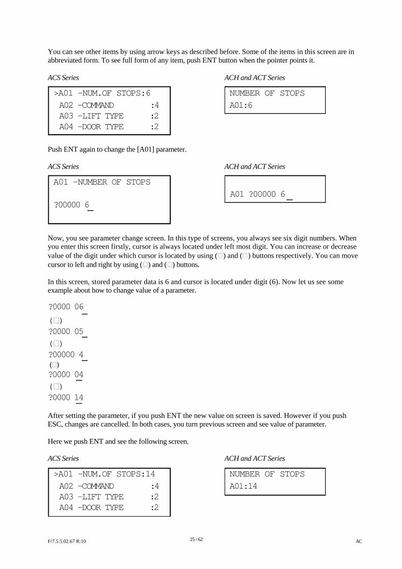
You can see other items by using arrow keys as described before. Some of the items in this screen are in abbreviated form. To see full form of any item, push ENT button when the pointer points it. ACS Series ACH and ACT Series
>A01 -NUM.OF STOPS:6 NUMBER OF STOPS A02 -COMMAND :4 A01:6 A03 -LIFT TYPE :2 A04 -DOOR TYPE :2
Push ENT again to change the [A01] parameter. ACS Series ACH and ACT Series
A01 -NUMBER OF STOPS
A01 ?00000 6 ?00000 6
Now, you see parameter change screen. In this type of screens, you always see six digit numbers. When you enter this screen firstly, cursor is always located under left most digit. You can increase or decrease value of the digit under which cursor is located by using () and () buttons respectively. You can move cursor to left and right by using () and () buttons. In this screen, stored parameter data is 6 and cursor is located under digit (6). Now let us see some example about how to change value of a parameter.
?0000 06
( ) ?0000 05
( ) ?00000 4 () ?0000 04 ( ) ?0000 14 After setting the parameter, if you push ENT the new value on screen is saved. However if you push ESC, changes are cancelled. In both cases, you turn previous screen and see value of parameter. Here we push ENT and see the following screen. ACS Series ACH and ACT Series
>A01 -NUM.OF STOPS:14 NUMBER OF STOPS
A02 -COMMAND :4 A01:14 A03 -LIFT TYPE :2 A04 -DOOR TYPE :2
F/7.5.5.02.67 R:10
25 / 62
AC
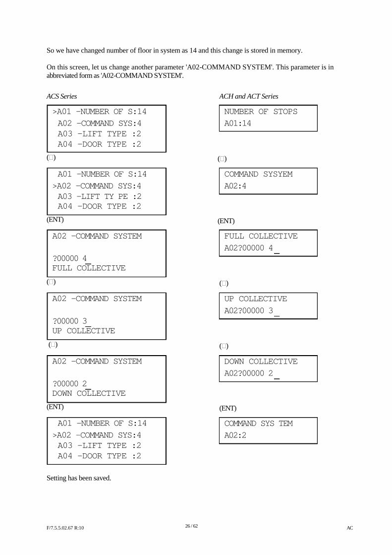
So we have changed number of floor in system as 14 and this change is stored in memory. On this screen, let us change another parameter 'A02-COMMAND SYSTEM'. This parameter is in abbreviated form as 'A02-COMMAND SYSTEM'.
ACS Series
>A01 -NUMBER OF S:14
A02 -COMMAND SYS:4 A03 -LIFT TYPE :2 A04 -DOOR TYPE :2
()
A01 -NUMBER OF S:14
>A02 -COMMAND SYS:4 A03 -LIFT TY PE :2 A04 -DOOR TYPE :2
(ENT)
A02 -COMMAND SYSTEM
?00000 4 FULL COLLECTIVE
()
A02 -COMMAND SYSTEM
?00000 3 UP COLLECTIVE
()
A02 -COMMAND SYSTEM
?00000 2 DOWN COLLECTIVE
(ENT)
A01 -NUMBER OF S:14
>A02 -COMMAND SYS:4 A03 -LIFT TYPE :2 A04 -DOOR TYPE :2
Setting has been saved.
ACH and ACT Series
NUMBER OF STOPS
A01:14
()
COMMAND SYSYEM
A02:4
(ENT)
FULL COLLECTIVE
A02?00000 4
()
UP COLLECTIVE
A02?00000 3
()
DOWN COLLECTIVE
A02?00000 2
(ENT)
COMMAND SYS TEM
A02:2
F/7.5.5.02.67 R:10
26 / 62
AC
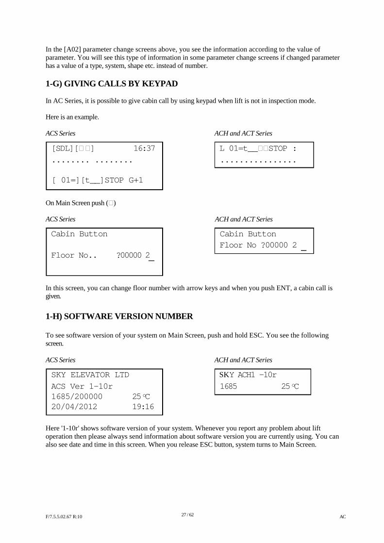
In the [A02] parameter change screens above, you see the information according to the value of parameter. You will see this type of information in some parameter change screens if changed parameter has a value of a type, system, shape etc. instead of number. 1-G) GIVING CALLS BY KEYPAD In AC Series, it is possible to give cabin call by using keypad when lift is not in inspection mode. Here is an example. ACS Series ACH and ACT Series
[SDL][ ] 16:37 L 01=t__STOP : ........ ........
[ 01=][t__]STOP G+1
On Main Screen push () ACS Series
Cabin Button
................
ACH and ACT Series
Cabin Button
Floor No ?00000 2 Floor No.. ?00000 2
In this screen, you can change floor number with arrow keys and when you push ENT, a cabin call is given.
1-H) SOFTWARE VERSION NUMBER To see software version of your system on Main Screen, push and hold ESC. You see the following screen. ACS Series ACH and ACT Series
SKY ELEVATOR LTD SKY ACH1 -10r
ACS Ver 1-10r 1685 25 oC 1685/200000 25 oC 20/04/2012 19:16
Here '1-10r' shows software version of your system. Whenever you report any problem about lift operation then please always send information about software version you are currently using. You can also see date and time in this screen. When you release ESC button, system turns to Main Screen.
F/7.5.5.02.67 R:10
27 / 62
AC
CHAPTER 2:
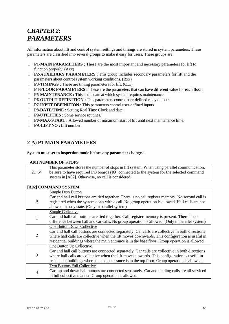
PARAMETERS All information about lift and control system settings and timings are stored in system parameters. These parameters are classified into several groups to make it easy for users. These groups are: P1-MAIN PARAMETERS : These are the most important and necessary parameters for lift to
function properly. (Axx) P2-AUXILIARY PARAMETERS : This group includes secondary parameters for lift and the
parameters about control system working conditions. (Bxx) P3-TIMINGS : These are timing parameters for lift. (Cxx) P4-FLOOR PARAMETERS : These are the parameters that can have different value for each floor. P5-MAINTENANCE : This is the date at which system requires maintenance. P6-OUTPUT DEFINITION : This parameters control user-defined relay outputs. P7-INPUT DEFINITION : This parameters control user-defined inputs. P8-DATE/TIME : Setting Real Time Clock and date. P9-UTILITIES : Some service routines. P0-MAX-START : Allowed number of maximum start of lift until next maintenance time. PA-LIFT NO : Lift number.
2-A) P1-MAIN PARAMETERS System must set to inspection mode before any parameter changes! [A01] NUMBER OF STOPS
This parameter stores the number of stops in lift system. When using parallel communication, 2…64 be sure to have required I/O boards (IO) connected to the system for the selected command
system in [A02]. Otherwise, no call is considered.
[A02] COMMAND SYSTEM Simple Push Button Car and hall call buttons are tied together. There is no call register memory. No second call is
0 1 2
3 4
registered when the system deals with a call. No group operation is allowed. Hall calls are not allowed in busy state. (Only in parallel system) Simple Collective Car and hall call buttons are tied together. Call register memory is present. There is no difference between hall and car calls. No group operation is allowed. (Only in parallel system) One Button Down Collective Car and hall call buttons are connected separately. Car calls are collective in both directions where hall calls are collective when the lift moves downwards. This configuration is useful in residential buildings where the main entrance is in the base floor. Group operation is allowed. One Button Up Collective Car and hall call buttons are connected separately. Car calls are collective in both directions where hall calls are collective when the lift moves upwards. This configuration is useful in residential buildings where the main entrance is in the top floor. Group operation is allowed. Two Buttons Full Collective Car, up and down hall buttons are connected separately. Car and landing calls are all serviced in full collective manner. Group operation is allowed.
F/7.5.5.02.67 R:10
28 / 62
AC
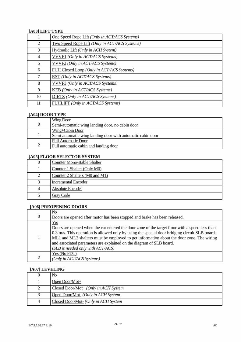
[A03] LIFT TYPE 1 2
3
4
5
6 7 8
9 10
11
One Speed Rope Lift (Only in ACT/ACS Systems) Two Speed Rope Lift (Only in ACT/ACS Systems) Hydraulic Lift (Only in ACH System)
VVVF1 (Only in ACT/ACS Systems)
VVVF2 (Only in ACT/ACS Systems) FUJI Closed Loop (Only in ACT/ACS Systems) RST (Only in ACT/ACS Systems) VVVF3 (Only in ACT/ACS Systems) KEB (Only in ACT/ACS Systems) DIETZ (Only in ACT/ACS Systems) FUJILIFT (Only in ACT/ACS Systems)
[A04] DOOR TYPE
Wing Door 0 1 2
Semi-automatic wing landing door, no cabin door Wing+Cabin Door Semi-automatic wing landing door with automatic cabin door Full Automatic Door Full automatic cabin and landing door
[A05] FLOOR SELECTOR SYSTEM
0 Counter Mono-stable Shalter 1 Counter 1 Shalter (Only M0) 2 Counter 2 Shalters (M0 and M1) 3 Incremental Encoder 4 Absolute Encoder 5 Gray Code
[A06] PREOPENING DOORS No
0
1 2
Doors are opened after motor has been stopped and brake has been released. Yes Doors are opened when the car entered the door zone of the target floor with a speed less than 0.3 m/s. This operation is allowed only by using the special door bridging circuit SLB board. ML1 and ML2 shalters must be employed to get information about the door zone. The wiring and associated parameters are explained on the diagram of SLB board. (SLB is needed only with ACT/ACS) Yes (No FDT) (Only in ACT/ACS Systems)
[A07] LEVELING
0 No 1 Open Door/Mot+ 2 Closed Door/Mot+ (Only in ACH System 3 Open Door/Mot- (Only in ACH System 4 Closed Door/Mot- (Only in ACH System
F/7.5.5.02.67 R:10
29 / 62
AC
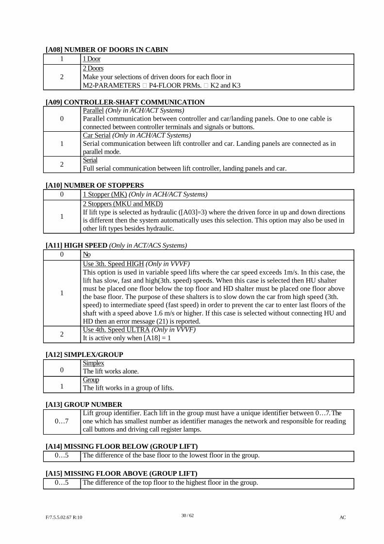
[A08] NUMBER OF DOORS IN CABIN 1 1 Door
2 Doors 2 Make your selections of driven doors for each floor in
M2-PARAMETERS P4-FLOOR PRMs. K2 and K3
[A09] CONTROLLER-SHAFT COMMUNICATION Parallel (Only in ACH/ACT Systems)
0 1 2
Parallel communication between controller and car/landing panels. One to one cable is connected between controller terminals and signals or buttons. Car Serial (Only in ACH/ACT Systems) Serial communication between lift controller and car. Landing panels are connected as in parallel mode. Serial Full serial communication between lift controller, landing panels and car.
[A10] NUMBER OF STOPPERS
0 1
1 Stopper (MK) (Only in ACH/ACT Systems) 2 Stoppers (MKU and MKD) If lift type is selected as hydraulic ([A03]=3) where the driven force in up and down directions is different then the system automatically uses this selection. This option may also be used in other lift types besides hydraulic.
[A11] HIGH SPEED (Only in ACT/ACS Systems)
0 1
2
No Use 3th. Speed HIGH (Only in VVVF) This option is used in variable speed lifts where the car speed exceeds 1m/s. In this case, the lift has slow, fast and high(3th. speed) speeds. When this case is selected then HU shalter must be placed one floor below the top floor and HD shalter must be placed one floor above the base floor. The purpose of these shalters is to slow down the car from high speed (3th. speed) to intermediate speed (fast speed) in order to prevent the car to enter last floors of the shaft with a speed above 1.6 m/s or higher. If this case is selected without connecting HU and HD then an error message (21) is reported. Use 4th. Speed ULTRA (Only in VVVF) It is active only when [A18] = 1
[A12] SIMPLEX/GROUP
Simplex 0 1
The lift works alone. Group The lift works in a group of lifts.
[A13] GROUP NUMBER
Lift group identifier. Each lift in the group must have a unique identifier between 0…7. The 0…7 one which has smallest number as identifier manages the network and responsible for reading
call buttons and driving call register lamps.
[A14] MISSING FLOOR BELOW (GROUP LIFT) 0…5 The difference of the base floor to the lowest floor in the group.
[A15] MISSING FLOOR ABOVE (GROUP LIFT)
0…5 The difference of the top floor to the highest floor in the group.
F/7.5.5.02.67 R:10
30 / 62
AC
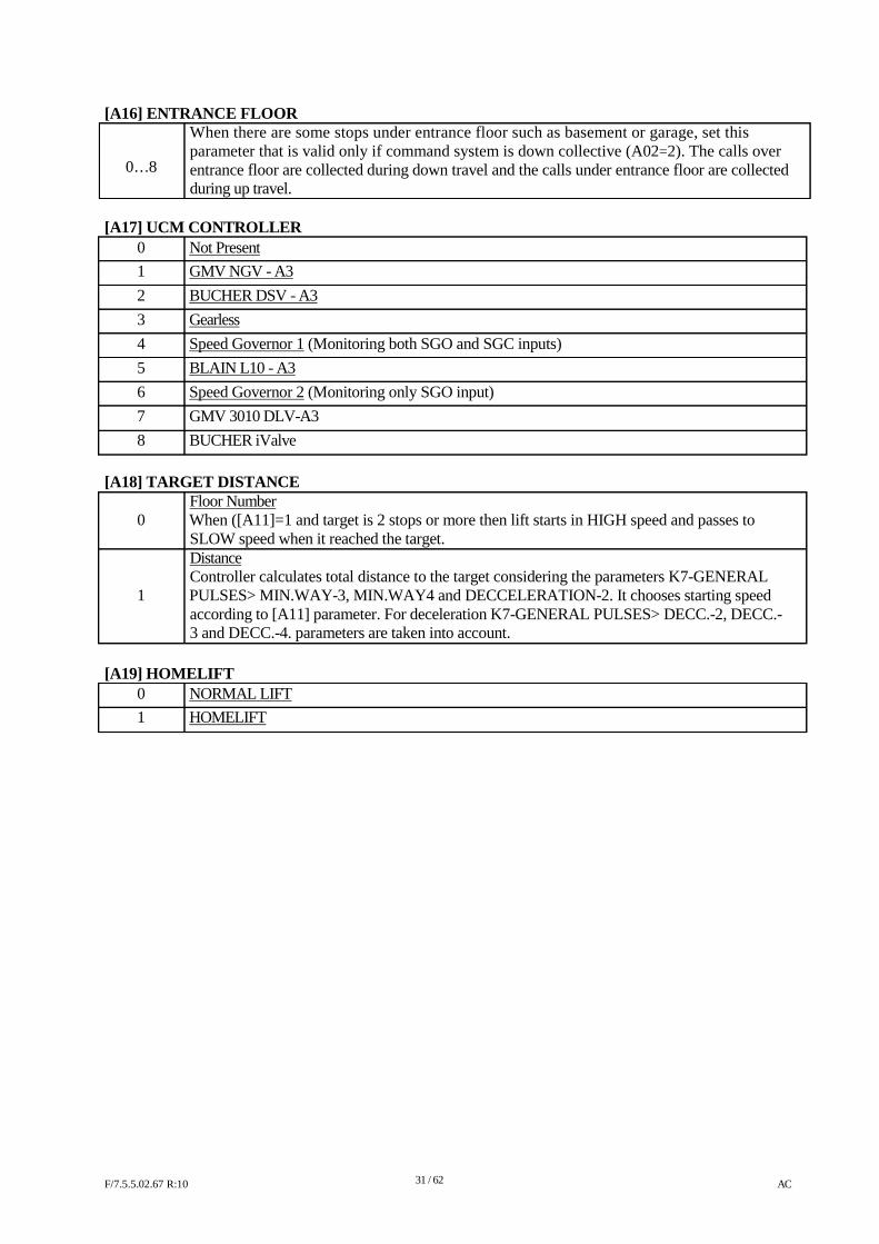
[A16] ENTRANCE FLOOR When there are some stops under entrance floor such as basement or garage, set this parameter that is valid only if command system is down collective (A02=2). The calls over
0…8 entrance floor are collected during down travel and the calls under entrance floor are collected during up travel.
[A17] UCM CONTROLLER
0 Not Present 1 GMV NGV - A3 2 BUCHER DSV - A3 3 Gearless 4 Speed Governor 1 (Monitoring both SGO and SGC inputs) 5 BLAIN L10 - A3 6 Speed Governor 2 (Monitoring only SGO input) 7 GMV 3010 DLV-A3 8 BUCHER iValve
[A18] TARGET DISTANCE Floor Number
0 When ([A11]=1 and target is 2 stops or more then lift starts in HIGH speed and passes to SLOW speed when it reached the target. Distance Controller calculates total distance to the target considering the parameters K7-GENERAL
1 PULSES> MIN.WAY-3, MIN.WAY4 and DECCELERATION-2. It chooses starting speed according to [A11] parameter. For deceleration K7-GENERAL PULSES> DECC.-2, DECC.- 3 and DECC.-4. parameters are taken into account.
[A19] HOMELIFT
0 NORMAL LIFT 1 HOMELIFT
F/7.5.5.02.67 R:10
31 / 62
AC
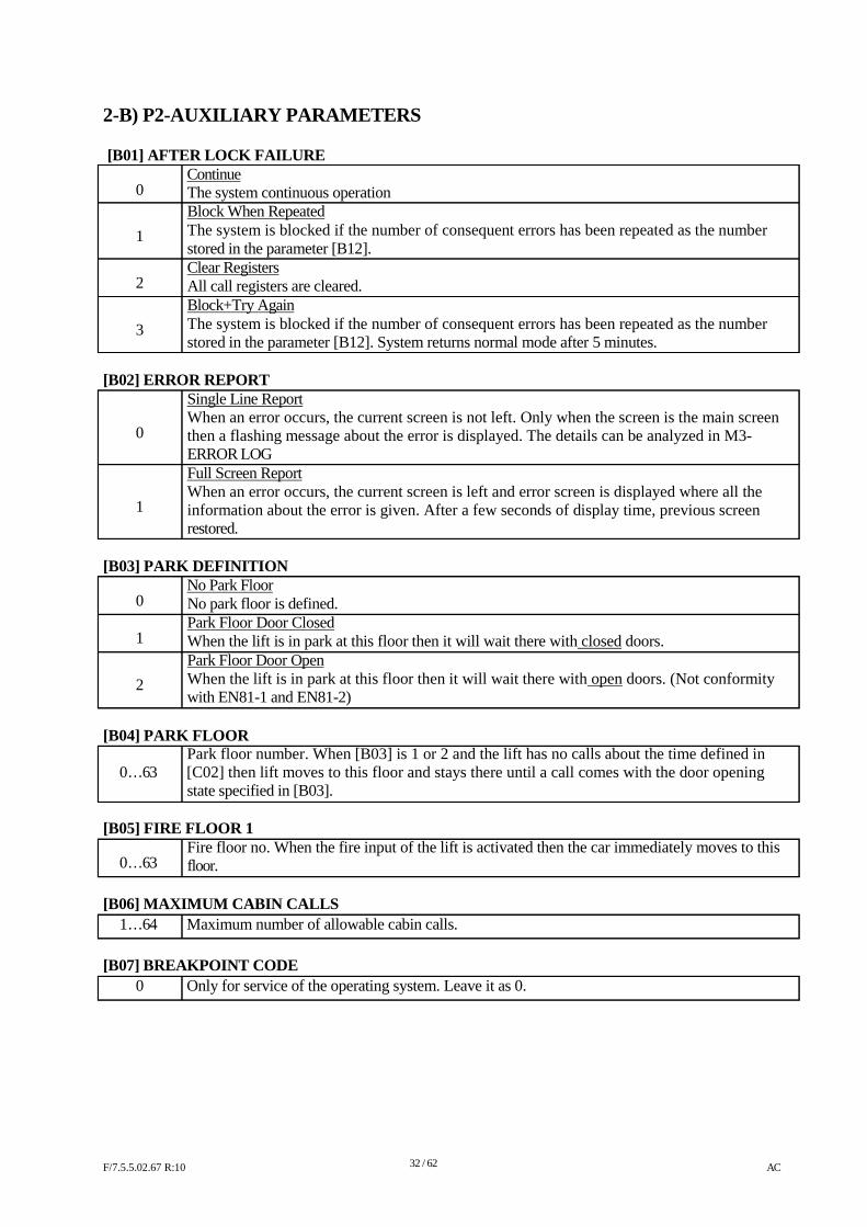
2-B) P2-AUXILIARY PARAMETERS [B01] AFTER LOCK FAILURE
Continue 0 1 2 3
The system continuous operation Block When Repeated The system is blocked if the number of consequent errors has been repeated as the number stored in the parameter [B12]. Clear Registers All call registers are cleared. Block+Try Again The system is blocked if the number of consequent errors has been repeated as the number stored in the parameter [B12]. System returns normal mode after 5 minutes.
[B02] ERROR REPORT
Single Line Report When an error occurs, the current screen is not left. Only when the screen is the main screen
0
1
then a flashing message about the error is displayed. The details can be analyzed in M3- ERROR LOG Full Screen Report When an error occurs, the current screen is left and error screen is displayed where all the information about the error is given. After a few seconds of display time, previous screen restored.
[B03] PARK DEFINITION
No Park Floor 0 1 2
No park floor is defined. Park Floor Door Closed When the lift is in park at this floor then it will wait there with closed doors. Park Floor Door Open When the lift is in park at this floor then it will wait there with open doors. (Not conformity with EN81-1 and EN81-2)
[B04] PARK FLOOR
Park floor number. When [B03] is 1 or 2 and the lift has no calls about the time defined in 0…63 [C02] then lift moves to this floor and stays there until a call comes with the door opening
state specified in [B03].
[B05] FIRE FLOOR 1 Fire floor no. When the fire input of the lift is activated then the car immediately moves to this
0…63 floor. [B06] MAXIMUM CABIN CALLS
1…64 Maximum number of allowable cabin calls.
[B07] BREAKPOINT CODE
0 Only for service of the operating system. Leave it as 0.
F/7.5.5.02.67 R:10
32 / 62
AC
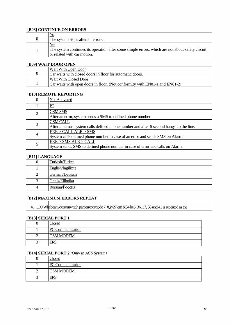
[B08] CONTINUE ON ERRORS No
0 1
The system stops after all errors. Yes The system continues its operation after some simple errors, which are not about safety circuit or related with car motion.
[B09] WAIT DOOR OPEN
Wait With Open Door 0 1
Car waits with closed doors in floor for automatic doors. Wait With Closed Door Car waits with open doors in floor. (Not conformity with EN81-1 and EN81-2)
[B10] REMOTE REPORTING
0 1
2 3 4 5
Not Activated PC GSM SMS After an error, system sends a SMS to defined phone number. GSM CALL After an error, system calls defined phone number and after 5 second hangs up the line. ERR > CALL ALR > SMS System calls defined phone number in case of an error and sends SMS on Alarm. ERR > SMS ALR > CALL System sends SMS to defined phone number in case of error and calls on Alarm.
[B11] LANGUAGE
0 Turkish/Turkce 1 English/İngilizce 2 German/Deutsch 3 Greek/Ellhnika 4 Russian/Россия
[B12] MAXIMUM ERRORS REPEAT
4…100 Whebeanyoerrornwhtih paraerreorrctode 7, 8,sy27,em bl34,ke5, 36, 37, 38 and 41 is repeated as the
[B13] SERIAL PORT 1
0 Closed 1 PC Communication 2 GSM MODEM 3 ERS
[B14] SERIAL PORT 2 (Only in ACS System)
0 Closed 1 PC Communication 2 GSM MODEM 3 ERS
F/7.5.5.02.67 R:10
33 / 62
AC
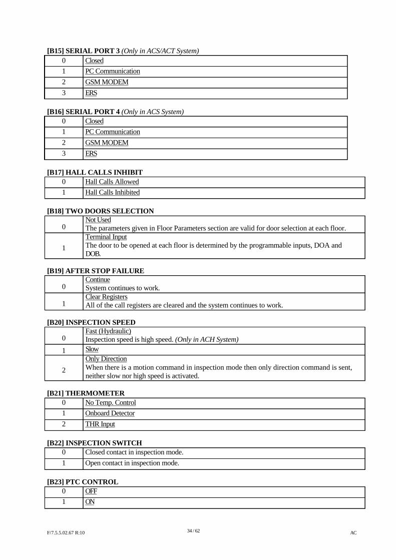
[B15] SERIAL PORT 3 (Only in ACS/ACT System) 0 Closed 1 PC Communication 2 GSM MODEM 3 ERS
[B16] SERIAL PORT 4 (Only in ACS System)
0 Closed 1 PC Communication 2 GSM MODEM 3 ERS
[B17] HALL CALLS INHIBIT
0 Hall Calls Allowed 1 Hall Calls Inhibited
[B18] TWO DOORS SELECTION Not Used
0 1
The parameters given in Floor Parameters section are valid for door selection at each floor. Terminal Input The door to be opened at each floor is determined by the programmable inputs, DOA and DOB.
[B19] AFTER STOP FAILURE
Continue 0 1
System continues to work. Clear Registers All of the call registers are cleared and the system continues to work.
[B20] INSPECTION SPEED
Fast (Hydraulic) 0
1
2
Inspection speed is high speed. (Only in ACH System) Slow Only Direction When there is a motion command in inspection mode then only direction command is sent, neither slow nor high speed is activated.
[B21] THERMOMETER
0 No Temp. Control 1 Onboard Detector 2 THR Input
[B22] INSPECTION SWITCH
0 Closed contact in inspection mode. 1 Open contact in inspection mode.
[B23] PTC CONTROL
0 OFF 1 ON
F/7.5.5.02.67 R:10
34 / 62
AC
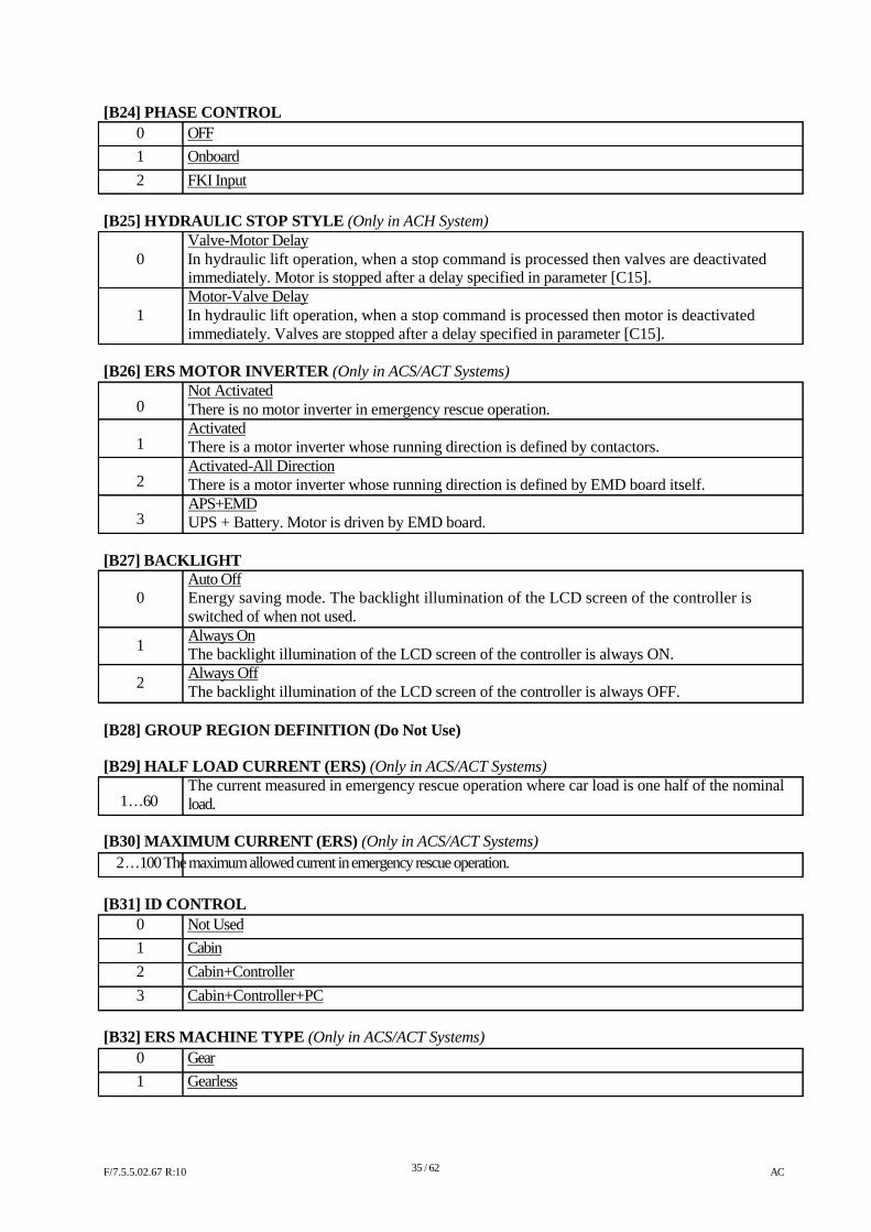
[B24] PHASE CONTROL 0 OFF 1 Onboard 2 FKI Input
[B25] HYDRAULIC STOP STYLE (Only in ACH System) Valve-Motor Delay
0 In hydraulic lift operation, when a stop command is processed then valves are deactivated immediately. Motor is stopped after a delay specified in parameter [C15]. Motor-Valve Delay
1 In hydraulic lift operation, when a stop command is processed then motor is deactivated immediately. Valves are stopped after a delay specified in parameter [C15].
[B26] ERS MOTOR INVERTER (Only in ACS/ACT Systems) Not Activated
0 1 2 3
There is no motor inverter in emergency rescue operation. Activated There is a motor inverter whose running direction is defined by contactors. Activated-All Direction There is a motor inverter whose running direction is defined by EMD board itself. APS+EMD UPS + Battery. Motor is driven by EMD board.
[B27] BACKLIGHT
Auto Off 0 1 2
Energy saving mode. The backlight illumination of the LCD screen of the controller is switched of when not used. Always On The backlight illumination of the LCD screen of the controller is always ON. Always Off The backlight illumination of the LCD screen of the controller is always OFF.
[B28] GROUP REGION DEFINITION (Do Not Use) [B29] HALF LOAD CURRENT (ERS) (Only in ACS/ACT Systems)
The current measured in emergency rescue operation where car load is one half of the nominal 1…60 load.
[B30] MAXIMUM CURRENT (ERS) (Only in ACS/ACT Systems)
2…100 The maximum allowed current in emergency rescue operation.
[B31] ID CONTROL
0 Not Used 1 Cabin 2 Cabin+Controller 3 Cabin+Controller+PC
[B32] ERS MACHINE TYPE (Only in ACS/ACT Systems)
0 Gear 1 Gearless
F/7.5.5.02.67 R:10
35 / 62
AC
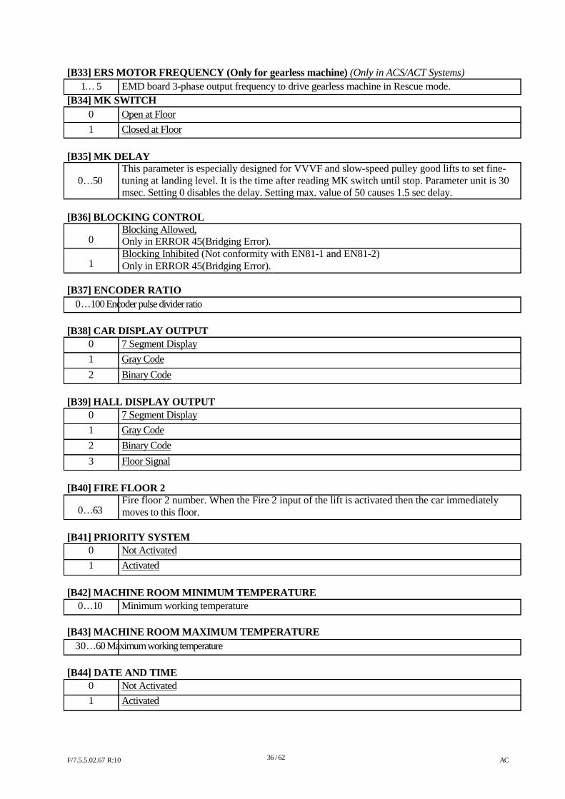
[B33] ERS MOTOR FREQUENCY (Only for gearless machine) (Only in ACS/ACT Systems) 1… 5 EMD board 3-phase output frequency to drive gearless machine in Rescue mode.
[B34] MK SWITCH 0 Open at Floor 1 Closed at Floor
[B35] MK DELAY
This parameter is especially designed for VVVF and slow-speed pulley good lifts to set fine- 0…50 tuning at landing level. It is the time after reading MK switch until stop. Parameter unit is 30
msec. Setting 0 disables the delay. Setting max. value of 50 causes 1.5 sec delay.
[B36] BLOCKING CONTROL Blocking Allowed,
0 1
Only in ERROR 45(Bridging Error). Blocking Inhibited (Not conformity with EN81-1 and EN81-2) Only in ERROR 45(Bridging Error).
[B37] ENCODER RATIO
0…100 Encoder pulse divider ratio
[B38] CAR DISPLAY OUTPUT
0 7 Segment Display 1 Gray Code 2 Binary Code
[B39] HALL DISPLAY OUTPUT
0 7 Segment Display 1 Gray Code 2 Binary Code 3 Floor Signal
[B40] FIRE FLOOR 2 Fire floor 2 number. When the Fire 2 input of the lift is activated then the car immediately
0…63 moves to this floor. [B41] PRIORITY SYSTEM
0 Not Activated 1 Activated
[B42] MACHINE ROOM MINIMUM TEMPERATURE
0…10 Minimum working temperature
[B43] MACHINE ROOM MAXIMUM TEMPERATURE 30…60 Maximum working temperature
[B44] DATE AND TIME
0 Not Activated 1 Activated
F/7.5.5.02.67 R:10
36 / 62
AC
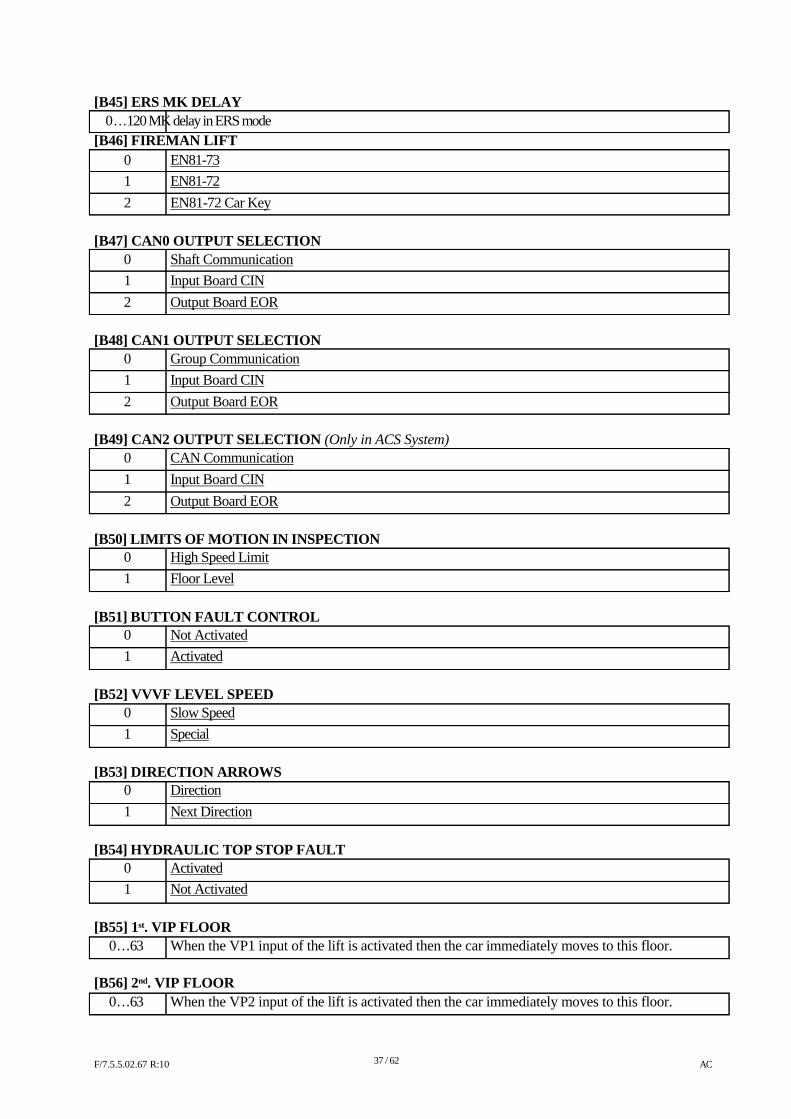
[B45] ERS MK DELAY 0…120 MK delay in ERS mode
[B46] FIREMAN LIFT 0 EN81-73 1 EN81-72 2 EN81-72 Car Key
[B47] CAN0 OUTPUT SELECTION
0 Shaft Communication 1 Input Board CIN 2 Output Board EOR
[B48] CAN1 OUTPUT SELECTION
0 Group Communication 1 Input Board CIN 2 Output Board EOR
[B49] CAN2 OUTPUT SELECTION (Only in ACS System)
0 CAN Communication 1 Input Board CIN 2 Output Board EOR
[B50] LIMITS OF MOTION IN INSPECTION
0 High Speed Limit 1 Floor Level
[B51] BUTTON FAULT CONTROL
0 Not Activated 1 Activated
[B52] VVVF LEVEL SPEED
0 Slow Speed 1 Special
[B53] DIRECTION ARROWS
0 Direction 1 Next Direction
[B54] HYDRAULIC TOP STOP FAULT
0 Activated 1 Not Activated
[B55] 1st. VIP FLOOR
0…63 When the VP1 input of the lift is activated then the car immediately moves to this floor.
[B56] 2nd. VIP FLOOR 0…63 When the VP2 input of the lift is activated then the car immediately moves to this floor.
F/7.5.5.02.67 R:10
37 / 62
AC
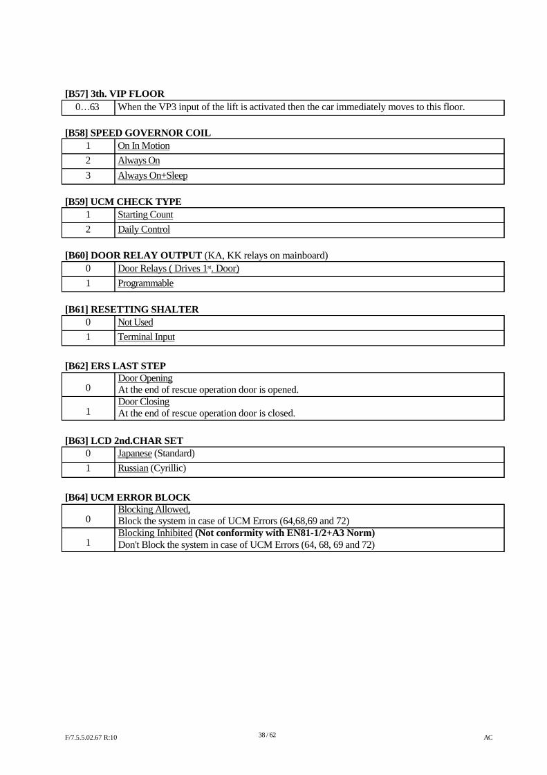
[B57] 3th. VIP FLOOR 0…63 When the VP3 input of the lift is activated then the car immediately moves to this floor.
[B58] SPEED GOVERNOR COIL
1 On In Motion 2 Always On 3 Always On+Sleep
[B59] UCM CHECK TYPE
1 Starting Count 2 Daily Control
[B60] DOOR RELAY OUTPUT (KA, KK relays on mainboard)
0 Door Relays ( Drives 1st. Door) 1 Programmable
[B61] RESETTING SHALTER
0 Not Used 1 Terminal Input
[B62] ERS LAST STEP
Door Opening 0 1
At the end of rescue operation door is opened. Door Closing At the end of rescue operation door is closed.
[B63] LCD 2nd.CHAR SET
0 Japanese (Standard) 1 Russian (Cyrillic)
[B64] UCM ERROR BLOCK
Blocking Allowed, 0 1
Block the system in case of UCM Errors (64,68,69 and 72) Blocking Inhibited (Not conformity with EN81-1/2+A3 Norm) Don't Block the system in case of UCM Errors (64, 68, 69 and 72)
F/7.5.5.02.67 R:10
38 / 62
AC
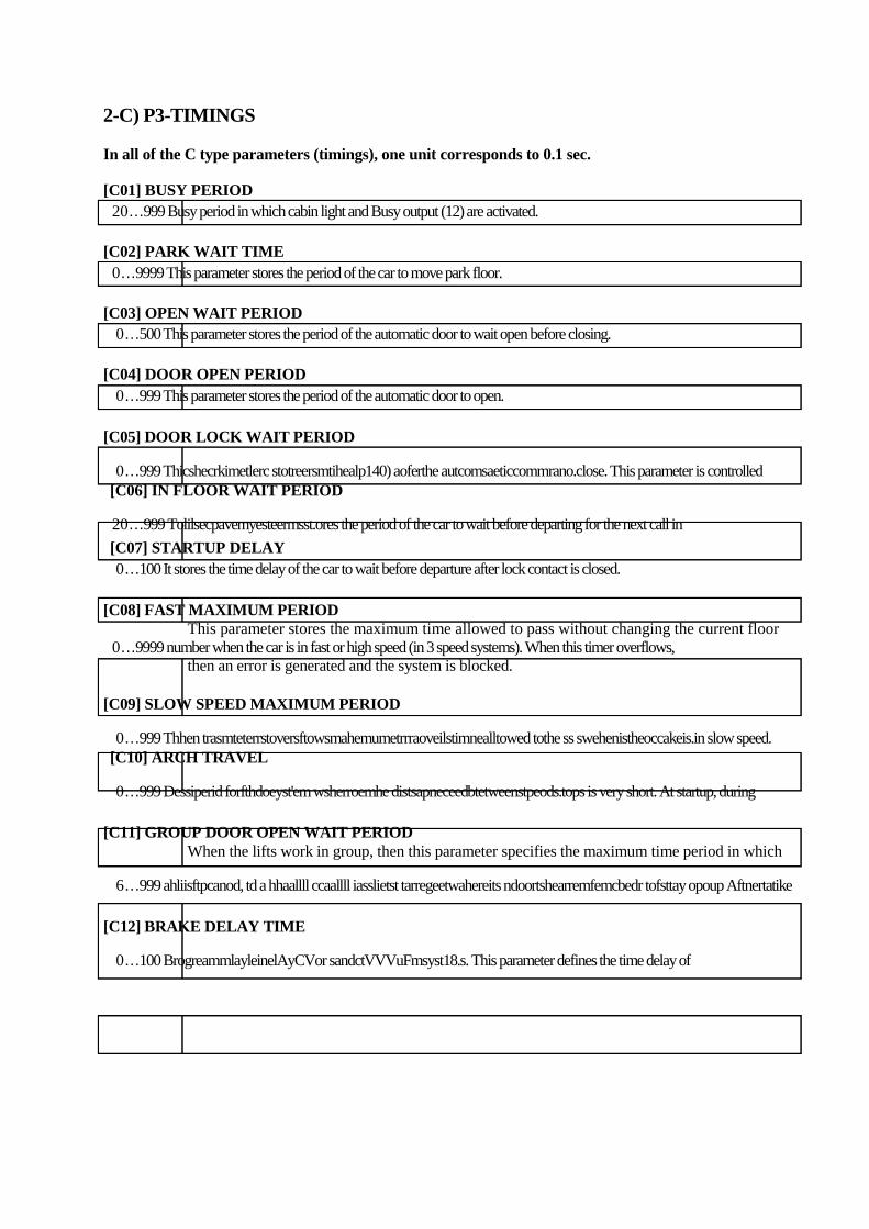
2-C) P3-TIMINGS In all of the C type parameters (timings), one unit corresponds to 0.1 sec. [C01] BUSY PERIOD 20…999 Busy period in which cabin light and Busy output (12) are activated.
[C02] PARK WAIT TIME 0…9999 This parameter stores the period of the car to move park floor.
[C03] OPEN WAIT PERIOD 0…500 This parameter stores the period of the automatic door to wait open before closing.
[C04] DOOR OPEN PERIOD 0…999 This parameter stores the period of the automatic door to open.
[C05] DOOR LOCK WAIT PERIOD
0…999 Thicshecrkimetlerc stotreersmtihealp140) aoferthe autcomsaeticcommrano.close. This parameter is controlled [C06] IN FLOOR WAIT PERIOD
20…999 Tolilsecpavemyesteermsst.ores the period of the car to wait before departing for the next call in
[C07] STARTUP DELAY 0…100 It stores the time delay of the car to wait before departure after lock contact is closed.
[C08] FAST MAXIMUM PERIOD This parameter stores the maximum time allowed to pass without changing the current floor
0…9999 number when the car is in fast or high speed (in 3 speed systems). When this timer overflows, then an error is generated and the system is blocked.
[C09] SLOW SPEED MAXIMUM PERIOD
0…999 Thhen trasmteterrstoversftowsmahemumetrrraoveilstimnealltowed tothe ss swehenistheoccakeis.in slow speed. [C10] ARCH TRAVEL
0…999 Dessiperid forfthdoeyst'em wsherroemhe distsapneceedbtetweenstpeods.tops is very short. At startup, during [C11] GROUP DOOR OPEN WAIT PERIOD
When the lifts work in group, then this parameter specifies the maximum time period in which
6…999 ahliisftpcanod, td a hhaallll ccaallll iasslietst tarregeetwahereits ndoortshearremfemcbedr tofsttay opoup Aftnertatike
[C12] BRAKE DELAY TIME
0…100 BrogreammlayleinelAyCVor sandctVVVuFmsyst18.s. This parameter defines the time delay of
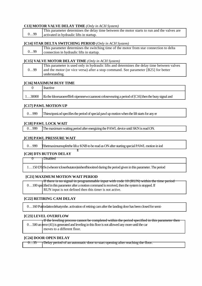
C13] MOTOR VALVE DELAY TIME (Only in ACH System) This parameter determines the delay time between the motor starts to run and the valves are
0…99 activated in hydraulic lifts in startup. [C14] STAR DELTA SWITCHING PERIOD (Only in ACH System)
This parameter determines the switching time of the motor from star connection to delta 0…99 connection in hydraulic lifts in startup.
[C15] VALVE MOTOR DELAY TIME (Only in ACH System)
This parameter is used only in hydraulic lifts and determines the delay time between valves 0…99 and the motor (or vice versa) after a stop command. See parameter [B25] for better
understanding.
[C16] MAXIMUM BUSY TIME 0 Inactive
1…30000 Ifa the ldoorsaraereflfeft oipennerwccaannost celoseveuring a period of [C16] then the busy signal and
[C17] PAWL MOTION UP
0…999 Thiesctponi.od specifies the period of special pawl up motion when the lift starts for any er
[C18] PAWL LOCK WAIT 0…999 The maximum waiting period after energizing the PAWL device until SKN is read ON.
[C19] PAWL PRESSURE WAIT
0…999 Tthetmaximumopfetrhe lifo.r KNB to be read as ON after starting special PAWL motion in iod
[C20] DTS BUTTON DELAY ft
0 Disabled
1…150 DTrSs (wheonr tcloserbutaton)sishenfhiooitred during the period given in this parameter. The period [C21] MAXIMUM MOTION WAIT PERIOD
If there is no signal in programmable input with code 10 (RUN) within the time period 0…100 specified in this parameter after a motion command is received, then the system is stopped. If
RUN input is not defined then this timer is not active.
[C22] RETIRING CAM DELAY
0…160 Putriodattocdelsatymhe. activation of retiring cam after the landing door has been closed for semi-
[C23] LEVEL OVERFLOW If the leveling process cannot be completed within the period specified in this parameter then
0…500 an error (41) is generated and leveling in this floor is not allowed any more until the car moves to a different floor.
[C24] DOOR OPEN DELAY 0…35 Delay period of an automatic door to start opening after reaching the floor.
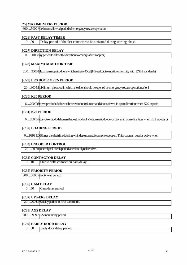
25] MAXIMUM ERS PERIOD 600…5000 Maximum allowed period of emergency rescue operation.
[C26] FAST DELAY TIMER
0…99 Delay period of the fast contactor to be activated during starting phase.
[C27] DIRECTION DELAY 0…110 Delay period to allow the direction to change after stopping.
[C28] MAXIMUM MOTOR TIME
200…3000 Maximutmsppairod ienewhichemhator450al(l45 eedct)oiswnortk.conformity with EN81 standards)
[C29] ERS DOOR OPEN PERIOD
20…300 Mraixiimum pleorood in which the door should be opened in emergency rescue operation after i
[C30] K20 PERIOD
6…200 Tchtiisvaperdiodt definesstehebeewiodno0.6uteomatid 8door.driven in open direction when K20 input is
[C31] K22 PERIOD
6…200 Tchtiisvpteerdiodt defninessthebeetrwodnof a6utsomaaticddooerc2 driven in open direction when K22 input is pi
[C32] LOADING PERIOD
0…9999 ItDBfiines the deefriinedduring whindep utomnttifcom photoceopen. Thisr-paprean pusrhis active when
[C33] ENCODER CONTROL 20…99 Encoder signal check period after last signal receive.
[C34] CONTACTOR DELAY
0…10 Star to delta connection pass delay.
[C35] PRIORITY PERIOD 300…3000 Priority wait period.
[C36] CAM DELAY
0…60 Cam delay period.
[C37] UPS-ERS DELAY 20…200 UPS delay period in ERS start mode.
[C38] AGS DELAY 100…9999 AGS input delay period.
[C39] EARLY DOOR DELAY
0…50 Early door delay period.
F/7.5.5.02.67 R:10
41 / 62
AC
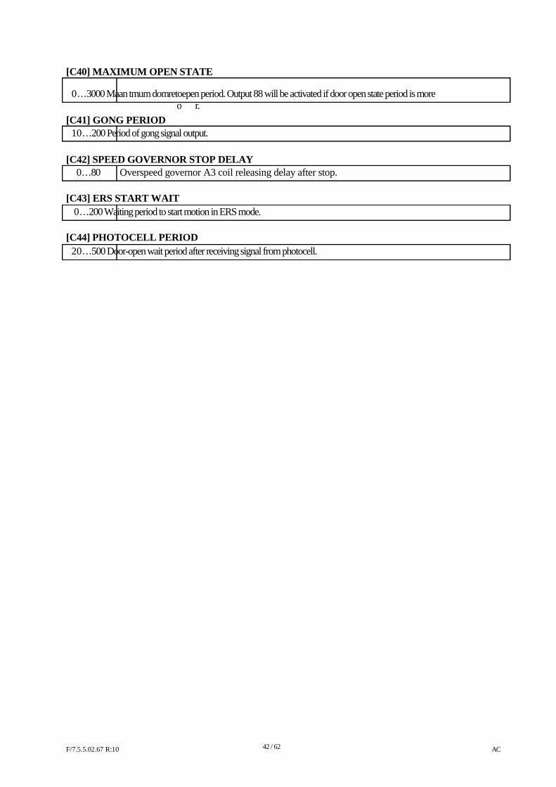
[C40] MAXIMUM OPEN STATE
0…3000 Maan tmum domretoepen period. Output 88 will be activated if door open state period is more
[C41] GONG PERIOD
o r.
10…200 Period of gong signal output.
[C42] SPEED GOVERNOR STOP DELAY
0…80 Overspeed governor A3 coil releasing delay after stop.
[C43] ERS START WAIT 0…200 Waiting period to start motion in ERS mode.
[C44] PHOTOCELL PERIOD 20…500 Door-open wait period after receiving signal from photocell.
F/7.5.5.02.67 R:10
42 / 62
AC
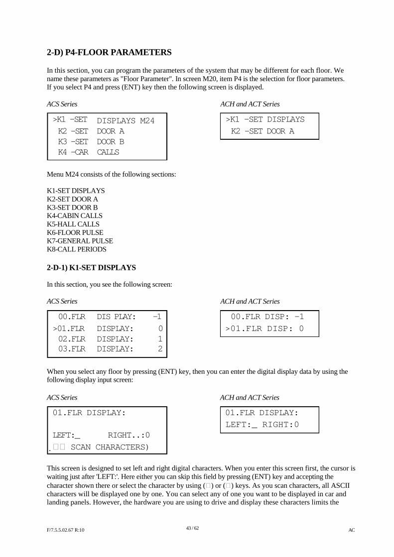
2-D) P4-FLOOR PARAMETERS In this section, you can program the parameters of the system that may be different for each floor. We name these parameters as "Floor Parameter". In screen M20, item P4 is the selection for floor parameters. If you select P4 and press (ENT) key then the following screen is displayed. ACS Series
>K1 -SET K2 -SET K3 -SET K4 -CAR
DISPLAYS M24 DOOR A DOOR B CALLS
ACH and ACT Series
>K1 -SET DISPLAYS
K2 -SET DOOR A
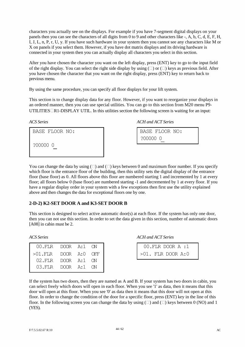
Menu M24 consists of the following sections: K1-SET DISPLAYS K2-SET DOOR A K3-SET DOOR B K4-CABIN CALLS K5-HALL CALLS K6-FLOOR PULSE K7-GENERAL PULSE K8-CALL PERIODS 2-D-1) K1-SET DISPLAYS In this section, you see the following screen: ACS Series
ACH and ACT Series
00.FLR DIS PLAY: -1 00.FLR DISP: -1
>01.FLR DISPLAY: 0 >01.FLR DISP: 0 02.FLR DISPLAY: 1 03.FLR DISPLAY: 2
When you select any floor by pressing (ENT) key, then you can enter the digital display data by using the following display input screen: ACS Series ACH and ACT Series
01.FLR DISPLAY: 01.FLR DISPLAY:
LEFT:_ RIGHT:0 LEFT:_ RIGHT..:0
SCAN CHARACTERS)
This screen is designed to set left and right digital characters. When you enter this screen first, the cursor is waiting just after 'LEFT:'. Here either you can skip this field by pressing (ENT) key and accepting the character shown there or select the character by using () or () keys. As you scan characters, all ASCII characters will be displayed one by one. You can select any of one you want to be displayed in car and landing panels. However, the hardware you are using to drive and display these characters limits the F/7.5.5.02.67 R:10
43 / 62
AC
characters you actually see on the displays. For example if you have 7-segment digital displays on your panels then you can see the characters of all digits from 0 to 9 and other characters like -, A, b, C, d, E, F, H, I, J, L, n, P, r, U, y. If you have such hardware in your system then you cannot see any characters like M or X on panels if you select them. However, if you have dot matrix displays and its driving hardware is connected in your system then you can actually display all characters you select in this section. After you have chosen the character you want on the left display, press (ENT) key to go to the input field of the right display. You can select the right side display by using () or () keys as previous field. After you have chosen the character that you want on the right display, press (ENT) key to return back to previous menu. By using the same procedure, you can specify all floor displays for your lift system. This section is to change display data for any floor. However, if you want to reorganize your displays in an ordered manner, then you can use special utilities. You can go to this section from M20 menu P9- UTILITIESR1-DISPLAY UTIL. In this utilities section the following screen is waiting for an input: ACS Series ACH and ACT Series
BASE FLOOR NO: BASE FLOOR NO:
?00000 0 ?00000 0
You can change the data by using () and () keys between 0 and maximum floor number. If you specify which floor is the entrance floor of the building, then this utility sets the digital display of the entrance floor (base floor) as 0. All floors above this floor are numbered starting 1 and incremented by 1 at every floor; all floors below 0 (base floor) are numbered starting -1 and decremented by 1 at every floor. If you have a regular display order in your system with a few exceptions then first use the utility explained above and then changes the data for exceptional floors one by one. 2-D-2) K2-SET DOOR A and K3-SET DOOR B This section is designed to select active automatic door(s) at each floor. If the system has only one door, then you can not use this section. In order to set the data given in this section, number of automatic doors [A08] in cabin must be 2.
ACS Series ACH and ACT Series
00.FLR DOOR A:1 ON 00.FLR DOOR A :1
>01.FLR DOOR A:0 OFF >01. FLR DOOR A:0 02.FLR DOOR A:1 ON 03.FLR DOOR A:1 ON
If the system has two doors, then they are named as A and B. If your system has two doors in cabin, you can select freely which doors will open in each floor. When you see '1' as data, then it means that this door will open at this floor. When you see '0' as data then it means that this door will not open at this floor. In order to change the condition of the door for a specific floor, press (ENT) key in the line of this floor. In the following screen you can change the data by using () and () keys between 0 (NO) and 1 (YES). F/7.5.5.02.67 R:10
44 / 62
AC
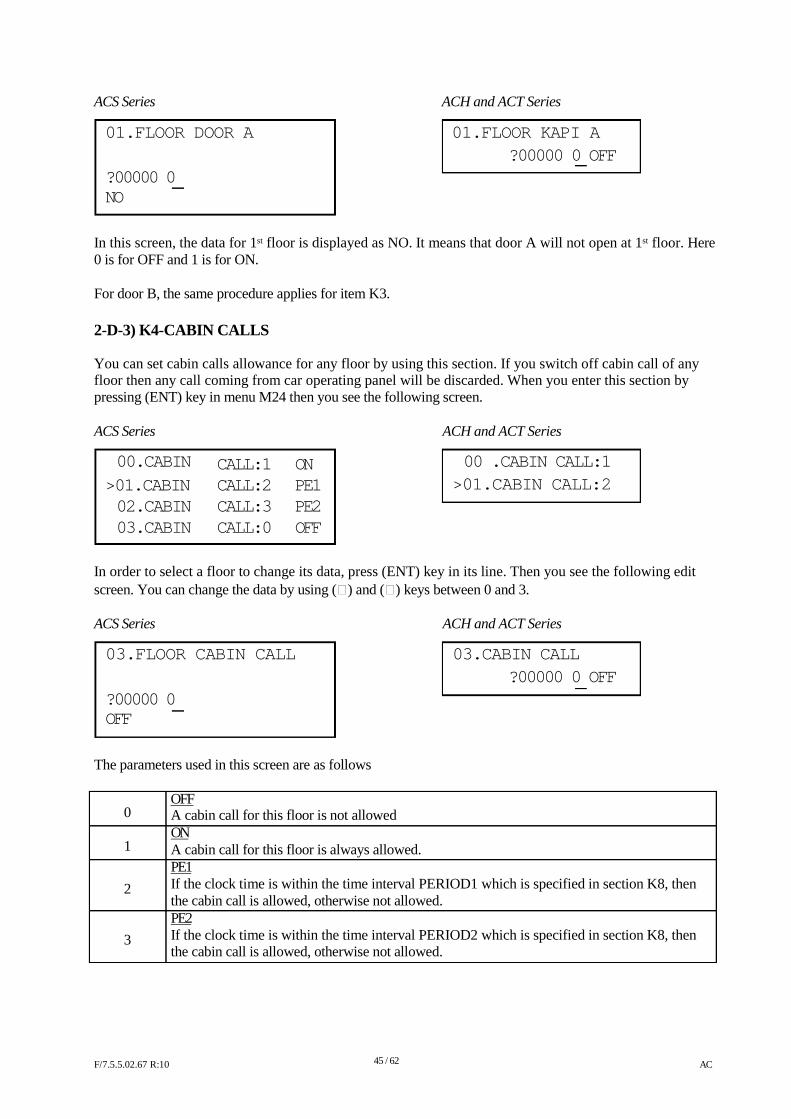
ACS Series ACH and ACT Series
01.FLOOR DOOR A 01.FLOOR KAPI A
?00000 0 OFF ?00000 0 NO
In this screen, the data for 1st floor is displayed as NO. It means that door A will not open at 1st floor. Here 0 is for OFF and 1 is for ON. For door B, the same procedure applies for item K3.
2-D-3) K4-CABIN CALLS You can set cabin calls allowance for any floor by using this section. If you switch off cabin call of any floor then any call coming from car operating panel will be discarded. When you enter this section by pressing (ENT) key in menu M24 then you see the following screen. ACS Series
00.CABIN
>01.CABIN 02.CABIN 03.CABIN
CALL:1 CALL:2 CALL:3 CALL:0
ON PE1 PE2 OFF
ACH and ACT Series
00 .CABIN CALL:1
>01.CABIN CALL:2
In order to select a floor to change its data, press (ENT) key in its line. Then you see the following edit screen. You can change the data by using () and () keys between 0 and 3. ACS Series
03.FLOOR CABIN CALL
?00000 0 OFF
The parameters used in this screen are as follows
OFF
ACH and ACT Series
03.CABIN CALL
?00000 0 OFF
0 1 2 3
A cabin call for this floor is not allowed ON A cabin call for this floor is always allowed. PE1 If the clock time is within the time interval PERIOD1 which is specified in section K8, then the cabin call is allowed, otherwise not allowed. PE2 If the clock time is within the time interval PERIOD2 which is specified in section K8, then the cabin call is allowed, otherwise not allowed.
F/7.5.5.02.67 R:10
45 / 62
AC
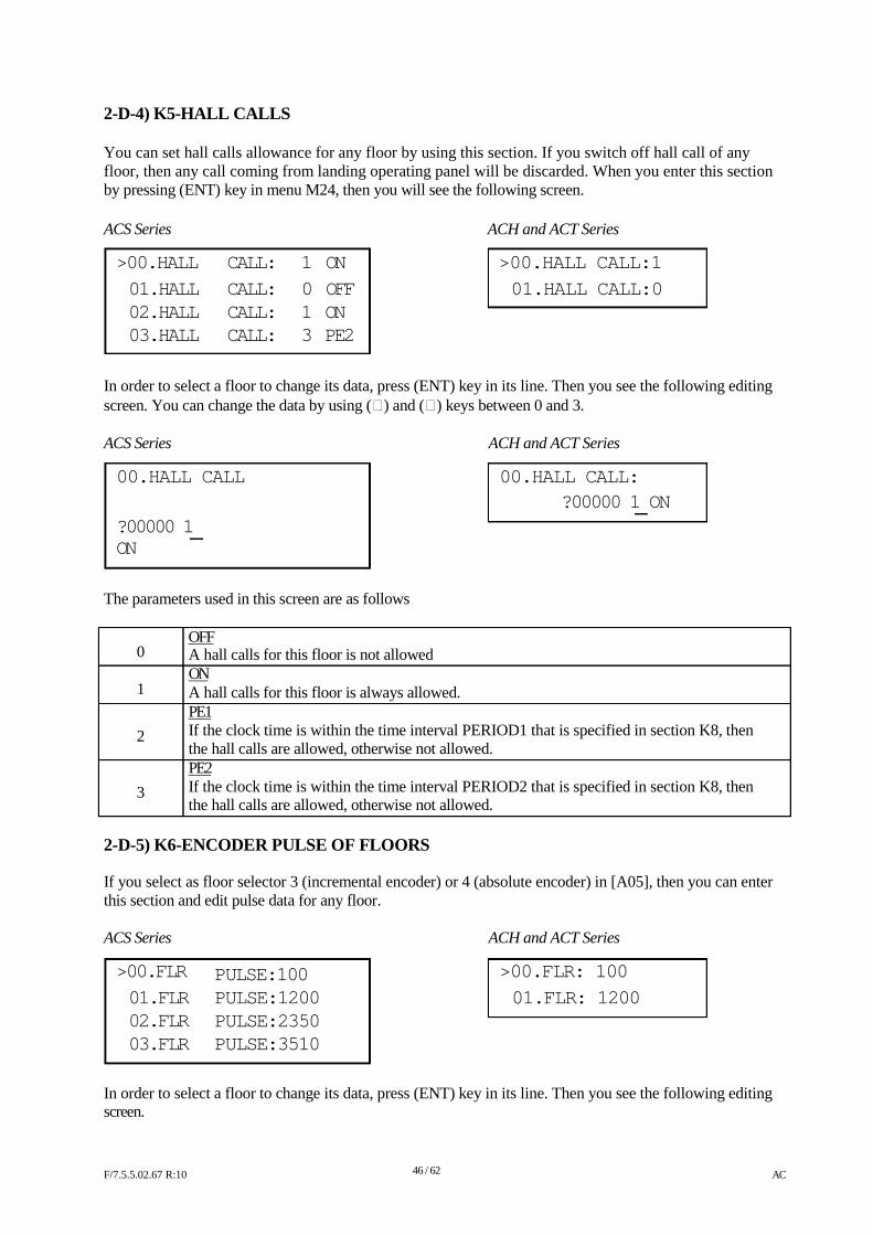
2-D-4) K5-HALL CALLS You can set hall calls allowance for any floor by using this section. If you switch off hall call of any floor, then any call coming from landing operating panel will be discarded. When you enter this section by pressing (ENT) key in menu M24, then you will see the following screen. ACS Series ACH and ACT Series
>00.HALL CALL: 1 ON >00.HALL CALL:1
01.HALL CALL: 0 OFF 01.HALL CALL:0 02.HALL CALL: 1 ON 03.HALL CALL: 3 PE2
In order to select a floor to change its data, press (ENT) key in its line. Then you see the following editing screen. You can change the data by using () and () keys between 0 and 3. ACS Series
00.HALL CALL
?00000 1 ON
The parameters used in this screen are as follows
OFF
ACH and ACT Series
00.HALL CALL:
?00000 1 ON
0 1 2 3
A hall calls for this floor is not allowed ON A hall calls for this floor is always allowed. PE1 If the clock time is within the time interval PERIOD1 that is specified in section K8, then the hall calls are allowed, otherwise not allowed. PE2 If the clock time is within the time interval PERIOD2 that is specified in section K8, then the hall calls are allowed, otherwise not allowed.
2-D-5) K6-ENCODER PULSE OF FLOORS If you select as floor selector 3 (incremental encoder) or 4 (absolute encoder) in [A05], then you can enter this section and edit pulse data for any floor. ACS Series
>00.FLR
01.FLR 02.FLR 03.FLR
PULSE:100 PULSE:1200 PULSE:2350 PULSE:3510
ACH and ACT Series
>00.FLR: 100
01.FLR: 1200
In order to select a floor to change its data, press (ENT) key in its line. Then you see the following editing screen. F/7.5.5.02.67 R:10
46 / 62
AC
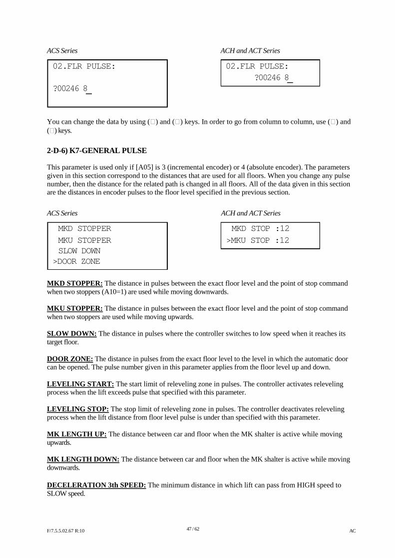
ACS Series ACH and ACT Series
02.FLR PULSE: 02.FLR PULSE:
?00246 8 ?00246 8
You can change the data by using () and () keys. In order to go from column to column, use () and () keys.
2-D-6) K7-GENERAL PULSE This parameter is used only if [A05] is 3 (incremental encoder) or 4 (absolute encoder). The parameters given in this section correspond to the distances that are used for all floors. When you change any pulse number, then the distance for the related path is changed in all floors. All of the data given in this section are the distances in encoder pulses to the floor level specified in the previous section.
ACS Series
MKD STOPPER
MKU STOPPER SLOW DOWN
>DOOR ZONE
ACH and ACT Series
MKD STOP :12
>MKU STOP :12
MKD STOPPER: The distance in pulses between the exact floor level and the point of stop command when two stoppers (A10=1) are used while moving downwards. MKU STOPPER: The distance in pulses between the exact floor level and the point of stop command when two stoppers are used while moving upwards. SLOW DOWN: The distance in pulses where the controller switches to low speed when it reaches its target floor. DOOR ZONE: The distance in pulses from the exact floor level to the level in which the automatic door can be opened. The pulse number given in this parameter applies from the floor level up and down. LEVELING START: The start limit of releveling zone in pulses. The controller activates releveling process when the lift exceeds pulse that specified with this parameter. LEVELING STOP: The stop limit of releveling zone in pulses. The controller deactivates releveling process when the lift distance from floor level pulse is under than specified with this parameter. MK LENGTH UP: The distance between car and floor when the MK shalter is active while moving upwards. MK LENGTH DOWN: The distance between car and floor when the MK shalter is active while moving downwards. DECELERATION 3th SPEED: The minimum distance in which lift can pass from HIGH speed to SLOW speed. F/7.5.5.02.67 R:10
47 / 62
AC
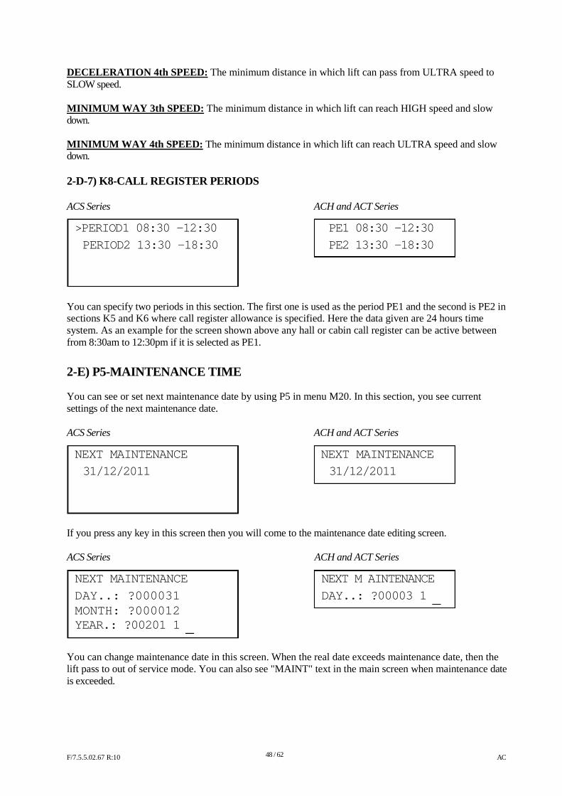
DECELERATION 4th SPEED: The minimum distance in which lift can pass from ULTRA speed to SLOW speed. MINIMUM WAY 3th SPEED: The minimum distance in which lift can reach HIGH speed and slow down. MINIMUM WAY 4th SPEED: The minimum distance in which lift can reach ULTRA speed and slow down. 2-D-7) K8-CALL REGISTER PERIODS ACS Series ACH and ACT Series
>PERIOD1 08:30 -12:30 PE1 08:30 -12:30
PERIOD2 13:30 -18:30 PE2 13:30 -18:30
You can specify two periods in this section. The first one is used as the period PE1 and the second is PE2 in sections K5 and K6 where call register allowance is specified. Here the data given are 24 hours time system. As an example for the screen shown above any hall or cabin call register can be active between from 8:30am to 12:30pm if it is selected as PE1.
2-E) P5-MAINTENANCE TIME You can see or set next maintenance date by using P5 in menu M20. In this section, you see current settings of the next maintenance date. ACS Series ACH and ACT Series
NEXT MAINTENANCE NEXT MAINTENANCE
31/12/2011 31/12/2011
If you press any key in this screen then you will come to the maintenance date editing screen. ACS Series
NEXT MAINTENANCE
DAY..: ?000031 MONTH: ?000012 YEAR.: ?00201 1
ACH and ACT Series
NEXT M AINTENANCE
DAY..: ?00003 1
You can change maintenance date in this screen. When the real date exceeds maintenance date, then the lift pass to out of service mode. You can also see "MAINT" text in the main screen when maintenance date is exceeded. F/7.5.5.02.67 R:10
48 / 62
AC
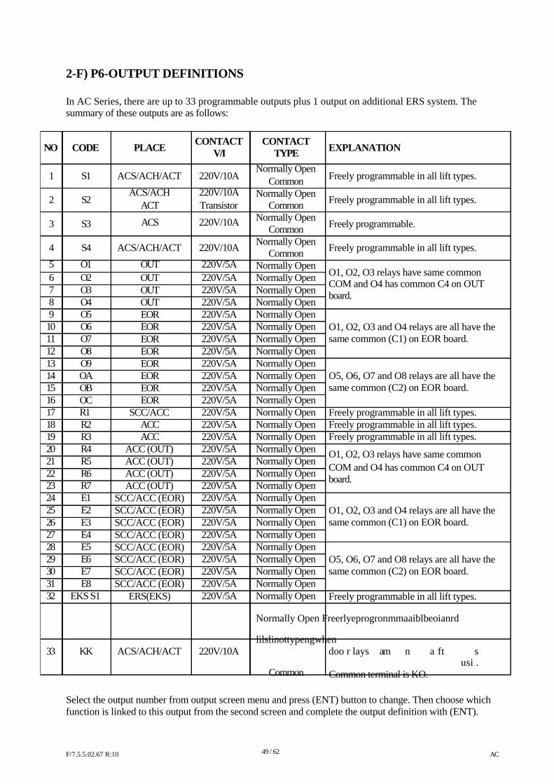
2-F) P6-OUTPUT DEFINITIONS
In AC Series, there are up to 33 programmable outputs plus 1 output on additional ERS system. The summary of these outputs are as follows:
NO
1 2 3 4
5 678 9 10 11 12 13 14 15 16 17 18 19 20 21 22 23 24 25 26 27 28 29 30 31 32
CODE
S1 S2 S3 S4
O1 O2 O3 O4 O5 O6 O7 O8 O9 OA OB OC R1 R2 R3 R4 R5 R6 R7 E1 E2 E3 E4 E5 E6 E7 E8
EKS S1
PLACE
ACS/ACH/ACT
ACS/ACH ACT
ACS
ACS/ACH/ACT
OUT OUT OUT OUT EOR EOR EOR EOR EOR EOR EOR EOR
SCC/ACC ACC ACC
ACC (OUT) ACC (OUT) ACC (OUT) ACC (OUT)
SCC/ACC (EOR) SCC/ACC (EOR) SCC/ACC (EOR) SCC/ACC (EOR) SCC/ACC (EOR) SCC/ACC (EOR) SCC/ACC (EOR) SCC/ACC (EOR)
ERS(EKS)
CONTACT
V/I
220V/10A
220V/10A Transistor
220V/10A 220V/10A
220V/5A 220V/5A 220V/5A 220V/5A 220V/5A 220V/5A 220V/5A 220V/5A 220V/5A 220V/5A 220V/5A 220V/5A 220V/5A 220V/5A 220V/5A 220V/5A 220V/5A 220V/5A 220V/5A 220V/5A 220V/5A 220V/5A 220V/5A 220V/5A 220V/5A 220V/5A 220V/5A 220V/5A
CONTACT
TYPE Normally Open
Common Normally Open
Common Normally Open
Common Normally Open
Common Normally Open Normally Open Normally Open Normally Open Normally Open Normally Open Normally Open Normally Open Normally Open Normally Open Normally Open Normally Open Normally Open Normally Open Normally Open Normally Open Normally Open Normally Open Normally Open Normally Open Normally Open Normally Open Normally Open Normally Open Normally Open Normally Open Normally Open Normally Open
EXPLANATION
Freely programmable in all lift types. Freely programmable in all lift types. Freely programmable. Freely programmable in all lift types. O1, O2, O3 relays have same common COM and O4 has common C4 on OUT board. O1, O2, O3 and O4 relays are all have the same common (C1) on EOR board. O5, O6, O7 and O8 relays are all have the same common (C2) on EOR board. Freely programmable in all lift types. Freely programmable in all lift types. Freely programmable in all lift types.
O1, O2, O3 relays have same common COM and O4 has common C4 on OUT board. O1, O2, O3 and O4 relays are all have the same common (C1) on EOR board. O5, O6, O7 and O8 relays are all have the same common (C2) on EOR board. Freely programmable in all lift types.
Normally Open Freerlyeprogronmmaaiblbeoianrd
lilslinottypengwhen 33 KK ACS/ACH/ACT 220V/10A doo r lays am n a ft s
usi . Common Common terminal is KO.
Select the output number from output screen menu and press (ENT) button to change. Then choose which function is linked to this output from the second screen and complete the output definition with (ENT). F/7.5.5.02.67 R:10
49 / 62
AC
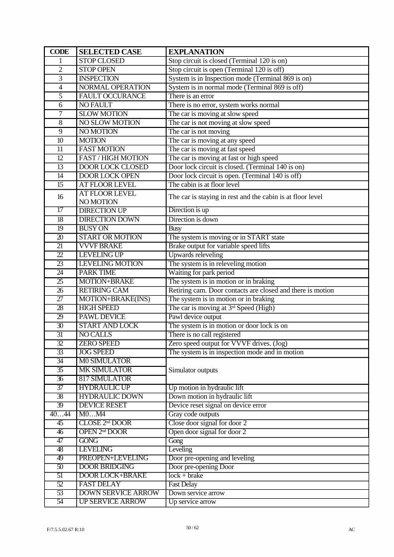
CODE 1 234 5 6789 10 11 12 13 14 15
16
17 18 19 20 21 22 23 24 25 26 27 28 29 30 31 32 33 34 35 36 37 38 39
40…44 45 46 47 48 49 50 51 52 53 54
SELECTED CASE STOP CLOSED STOP OPEN INSPECTION NORMAL OPERATION FAULT OCCURANCE NO FAULT SLOW MOTION NO SLOW MOTION NO MOTION MOTION FAST MOTION FAST / HIGH MOTION DOOR LOCK CLOSED DOOR LOCK OPEN AT FLOOR LEVEL AT FLOOR LEVEL NO MOTION DIRECTION UP DIRECTION DOWN BUSY ON START OR MOTION VVVF BRAKE LEVELING UP LEVELING MOTION PARK TIME MOTION+BRAKE RETIRING CAM MOTION+BRAKE(INS) HIGH SPEED PAWL DEVICE START AND LOCK NO CALLS ZERO SPEED JOG SPEED M0 SIMULATOR MK SIMULATOR 817 SIMULATOR HYDRAULIC UP HYDRAULIC DOWN DEVICE RESET M0…M4 CLOSE 2nd DOOR OPEN 2nd DOOR GONG LEVELING PREOPEN+LEVELING DOOR BRIDGING DOOR LOCK+BRAKE FAST DELAY DOWN SERVICE ARROW UP SERVICE ARROW
EXPLANATION Stop circuit is closed (Terminal 120 is on) Stop circuit is open (Terminal 120 is off) System is in Inspection mode (Terminal 869 is on) System is in normal mode (Terminal 869 is off) There is an error There is no error, system works normal The car is moving at slow speed The car is not moving at slow speed The car is not moving The car is moving at any speed The car is moving at fast speed The car is moving at fast or high speed Door lock circuit is closed. (Terminal 140 is on) Door lock circuit is open. (Terminal 140 is off) The cabin is at floor level
The car is staying in rest and the cabin is at floor level
Direction is up Direction is down Busy The system is moving or in START state Brake output for variable speed lifts Upwards releveling The system is in releveling motion Waiting for park period The system is in motion or in braking Retiring cam. Door contacts are closed and there is motion The system is in motion or in braking The car is moving at 3rd Speed (High) Pawl device output The system is in motion or door lock is on There is no call registered Zero speed output for VVVF drives. (Jog) The system is in inspection mode and in motion Simulator outputs Up motion in hydraulic lift Down motion in hydraulic lift Device reset signal on device error Gray code outputs Close door signal for door 2 Open door signal for door 2 Gong Leveling Door pre-opening and leveling Door pre-opening Door lock + brake Fast Delay Down service arrow Up service arrow
F/7.5.5.02.67 R:10
50 / 62
AC
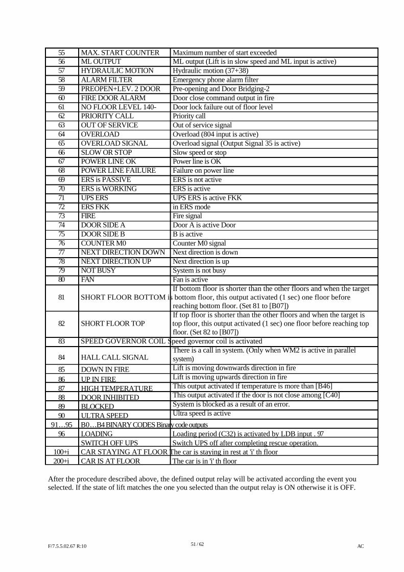
55 56 57 58 59 60 61 62 63 64 65 66 67 68 69 70 71 72 73 74 75 76 77 78 79 80
MAX. START COUNTER ML OUTPUT HYDRAULIC MOTION ALARM FILTER PREOPEN+LEV. 2 DOOR FIRE DOOR ALARM NO FLOOR LEVEL 140- PRIORITY CALL OUT OF SERVICE OVERLOAD OVERLOAD SIGNAL SLOW OR STOP POWER LINE OK POWER LINE FAILURE ERS is PASSIVE ERS is WORKING UPS ERS ERS FKK FIRE DOOR SIDE A DOOR SIDE B COUNTER M0 NEXT DIRECTION DOWN NEXT DIRECTION UP NOT BUSY FAN
Maximum number of start exceeded ML output (Lift is in slow speed and ML input is active) Hydraulic motion (37+38) Emergency phone alarm filter Pre-opening and Door Bridging-2 Door close command output in fire Door lock failure out of floor level Priority call Out of service signal Overload (804 input is active) Overload signal (Output Signal 35 is active) Slow speed or stop Power line is OK Failure on power line ERS is not active ERS is active UPS ERS is active FKK in ERS mode Fire signal Door A is active Door B is active Counter M0 signal Next direction is down Next direction is up System is not busy Fan is active If bottom floor is shorter than the other floors and when the target
81 SHORT FLOOR BOTTOM is bottom floor, this output activated (1 sec) one floor before reaching bottom floor. (Set 81 to [B07]) If top floor is shorter than the other floors and when the target is
82 SHORT FLOOR TOP top floor, this output activated (1 sec) one floor before reaching top floor. (Set 82 to [B07])
83 SPEED GOVERNOR COIL Speed governor coil is activated There is a call in system. (Only when WM2 is active in parallel
84
85 86 87 88 89 90
HALL CALL SIGNAL
DOWN IN FIRE UP IN FIRE HIGH TEMPERATURE DOOR INHIBITED BLOCKED ULTRA SPEED
system) Lift is moving downwards direction in fire Lift is moving upwards direction in fire This output activated if temperature is more than [B46] This output activated if the door is not close among [C40] System is blocked as a result of an error. Ultra speed is active
91…95 B0…B4 BINARY CODES Binary code outputs 96 LOADING Loading period (C32) is activated by LDB input . 97 SWITCH OFF UPS Switch UPS off after completing rescue operation.
100+i CAR STAYING AT FLOOR The car is staying in rest at 'i' th floor 200+i CAR IS AT FLOOR The car is in 'i' th floor
After the procedure described above, the defined output relay will be activated according the event you selected. If the state of lift matches the one you selected than the output relay is ON otherwise it is OFF.
F/7.5.5.02.67 R:10
51 / 62
AC
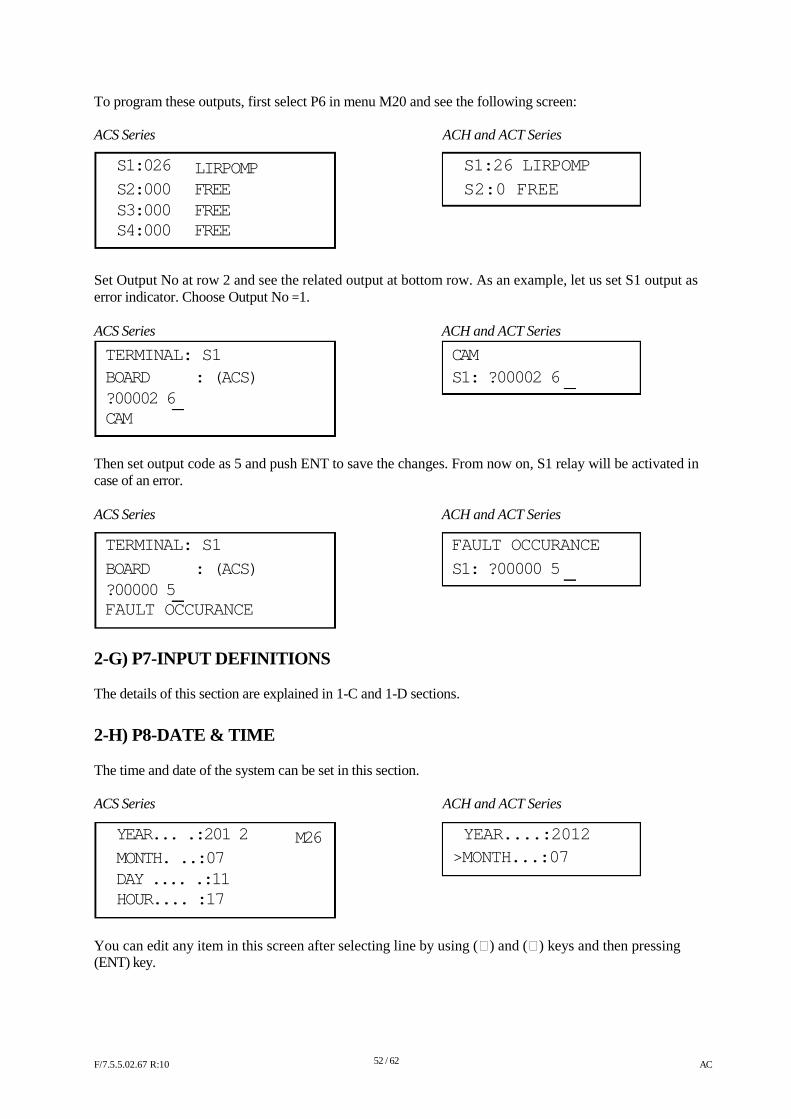
To program these outputs, first select P6 in menu M20 and see the following screen: ACS Series
S1:026
S2:000 S3:000 S4:000
LIRPOMP FREE FREE FREE
ACH and ACT Series
S1:26 LIRPOMP
S2:0 FREE
Set Output No at row 2 and see the related output at bottom row. As an example, let us set S1 output as error indicator. Choose Output No =1. ACS Series ACH and ACT Series
TERMINAL: S1 CAM BOARD : (ACS) S1: ?00002 6 ?00002 6 CAM
Then set output code as 5 and push ENT to save the changes. From now on, S1 relay will be activated in case of an error. ACS Series ACH and ACT Series
TERMINAL: S1 FAULT OCCURANCE
BOARD : (ACS) S1: ?00000 5 ?00000 5 FAULT OCCURANCE
2-G) P7-INPUT DEFINITIONS The details of this section are explained in 1-C and 1-D sections.
2-H) P8-DATE & TIME The time and date of the system can be set in this section. ACS Series
YEAR... .:201 2 MONTH. ..:07 DAY .... .:11 HOUR.... :17
M26
ACH and ACT Series
YEAR....:2012
>MONTH...:07
You can edit any item in this screen after selecting line by using () and () keys and then pressing (ENT) key.
F/7.5.5.02.67 R:10
52 / 62
AC
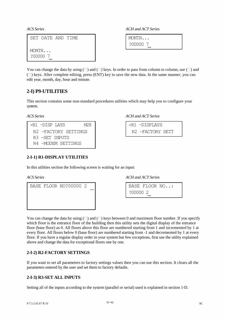
ACS Series ACH and ACT Series
SET DATE AND TIME MONTH...
?00000 7 MONTH... ?00000 7
You can change the data by using () and () keys. In order to pass from column to column, use () and () keys. After complete editing, press (ENT) key to save the new data. In the same manner, you can edit year, month, day, hour and minute.
2-I) P9-UTILITIES This section contains some non-standard procedures utilities which may help you to configure your system. ACS Series ACH and ACT Series
>R1 -DISP LAYS M28 >R1 -DISPLAYS
R2 -FACTORY SETTINGS R2 -FACTORY SETT R3 -SET INPUTS R4 -MODEM SETTINGS
2-I-1) R1-DISPLAY UTILITIES In this utilities section the following screen is waiting for an input: ACS Series ACH and ACT Series
BASE FLOOR NO?00000 2 BASE FLOOR NO..:
?00000 2
You can change the data by using () and () keys between 0 and maximum floor number. If you specify which floor is the entrance floor of the building then this utility sets the digital display of the entrance floor (base floor) as 0. All floors above this floor are numbered starting from 1 and incremented by 1 at every floor. All floors below 0 (base floor) are numbered starting from -1 and decremented by 1 at every floor. If you have a regular display order in your system but few exceptions, first use the utility explained above and change the data for exceptional floors one by one.
2-I-2) R2-FACTORY SETTINGS If you want to set all parameters to factory settings values then you can use this section. It clears all the parameters entered by the user and set them to factory defaults. 2-I-3) R3-SET ALL INPUTS Setting all of the inputs according to the system (parallel or serial) used is explained in section 1-D. F/7.5.5.02.67 R:10
53 / 62
AC
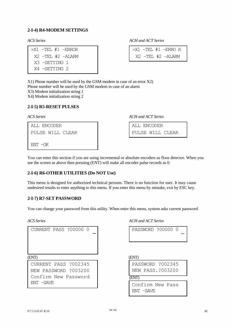
2-I-4) R4-MODEM SETTINGS ACS Series
>X1 -TEL #1 -ERROR
X2 -TEL #2 -ALARM X3 -SETTING 1 X4 -SETTING 2
ACH and ACT Series
>X1 -TEL #1 -ERRO R
X2 -TEL #2 -ALARM
X1) Phone number will be used by the GSM modem in case of an error X2) Phone number will be used by the GSM modem in case of an alarm X3) Modem initialization string 1 X4) Modem initialization string 2 2-I-5) R5-RESET PULSES ACS Series ACH and ACT Series
ALL ENCODER ALL ENCODER
PULSE WILL CLEAR PULSE WILL CLEAR
ENT -OK
You can enter this section if you are using incremental or absolute encoders as floor detector. When you see the screen as above then pressing (ENT) will make all encoder pulse records as 0. 2-I-6) R6-OTHER UTILITIES (Do NOT Use) This menu is designed for authorized technical persons. There is no function for user. It may cause undesired results to enter anything to this menu. If you enter this menu by mistake, exit by ESC key. 2-I-7) R7-SET PASSWORD You can change your password from this utility. When enter this menu, system asks current password.
ACS Series ACH and ACT Series
CURRENT PASS ?00000 0 PASSWORD ?00000 0
(ENT)
CURRENT PASS ?002345 NEW PASSWORD ?003200 Confirm New Password ENT -SAVE
(ENT)
PASSWORD ?002345 NEW PASS.?003200
(ENT)
Confirm New Pass ENT -SAVE
F/7.5.5.02.67 R:10
54 / 62
AC
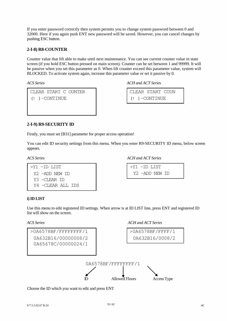
If you enter password correctly then system permits you to change system password between 0 and 32000. Here if you again push ENT new password will be saved. However, you can cancel changes by pushing ESC button. 2-I-8) R8-COUNTER Counter value that lift able to make until next maintenance. You can see current counter value in state screen (if you hold ESC button pressed on main screen). Counter can be set between 1 and 99999. It will be passive when you set this parameter as 0. When lift counter exceed this parameter value, system will BLOCKED. To activate system again, increase this parameter value or set it passive by 0. ACS Series ACH and ACT Series
CLEAR START C OUNTER CLEAR START COUN
(↑ )-CONTINUE (↑ )-CONTINUE
2-I-9) R9-SECURITY ID Firstly, you must set [B31] parameter for proper access operation! You can edit ID security settings from this menu. When you enter R9-SECURITY ID menu, below screen appears. ACS Series
>Y1 -ID LIST Y2 -ADD NEW ID Y3 -CLEAR ID Y4 -CLEAR ALL IDS
i) ID LIST
ACH and ACT Series
>Y1 -ID LIST Y2 -ADD NEW ID
Use this menu to edit registered ID settings. When arrow is at ID LIST line, press ENT and registered ID list will show on the screen. ACS Series ACH and ACT Series
>0A6578BF/FFFFFFFF/1 >0A6578BF/FFFF/1
0A632B16/00000008/2 0A632B16/0008/2 0A65678C/00000024/1
0A6578BF/FFFFFFFF/1
ID Allowed Floors Access Type
Choose the ID which you want to edit and press ENT F/7.5.5.02.67 R:10
55 / 62
AC
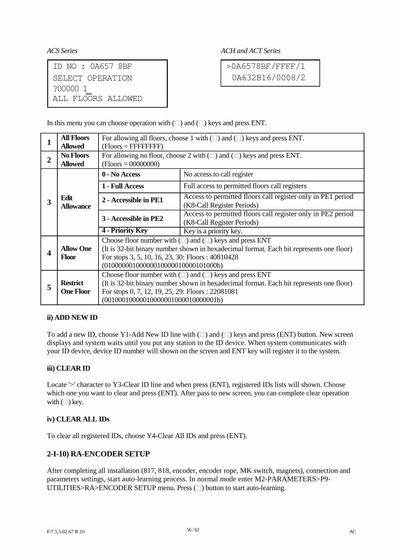
ACS Series
ID NO : 0A657 8BF
SELECT OPERATION ?00000 1 ALL FLOORS ALLOWED
ACH and ACT Series
>0A6578BF/FFFF/1
0A632B16/0008/2
In this menu you can choose operation with () and () keys and press ENT.
1 2
All Floors Allowed No Floors Allowed
For allowing all floors, choose 1 with () and () keys and press ENT. (Floors = FFFFFFFF) For allowing no floor, choose 2 with () and () keys and press ENT. (Floors = 00000000)
3
Edit Allowance
0 - No Access
1 - Full Access
2 - Accessible in PE1 3 - Accessible in PE2
4 - Priority Key
No access to call register
Full access to permitted floors call registers Access to permitted floors call register only in PE1 period (K8-Call Register Periods) Access to permitted floors call register only in PE2 period (K8-Call Register Periods) Key is a priority key.
4 5
Allow One Floor Restrict One Floor
Choose floor number with () and () keys and press ENT (It is 32-bit binary number shown in hexadecimal format. Each bit represents one floor) For stops 3, 5, 10, 16, 23, 30: Floors : 40810428 (01000000100000010000010000101000b) Choose floor number with () and () keys and press ENT (It is 32-bit binary number shown in hexadecimal format. Each bit represents one floor) For stops 0, 7, 12, 19, 25, 29: Floors : 22081081 (00100010000010000001000010000001b)
ii) ADD NEW ID To add a new ID, choose Y1-Add New ID line with () and () keys and press (ENT) button. New screen displays and system waits until you put any station to the ID device. When system communicates with your ID device, device ID number will shown on the screen and ENT key will register it to the system. iii) CLEAR ID Locate '>' character to Y3-Clear ID line and when press (ENT), registered IDs lists will shown. Choose which one you want to clear and press (ENT). After pass to new screen, you can complete clear operation with () key. iv) CLEAR ALL IDs To clear all registered IDs, choose Y4-Clear All IDs and press (ENT). 2-I-10) RA-ENCODER SETUP After completing all installation (817, 818, encoder, encoder rope, MK switch, magnets), connection and parameters settings, start auto-learning process. In normal mode enter M2-PARAMETERS>P9- UTILITIES>RA>ENCODER SETUP menu. Press () button to start auto-learning. F/7.5.5.02.67 R:10
56 / 62
AC
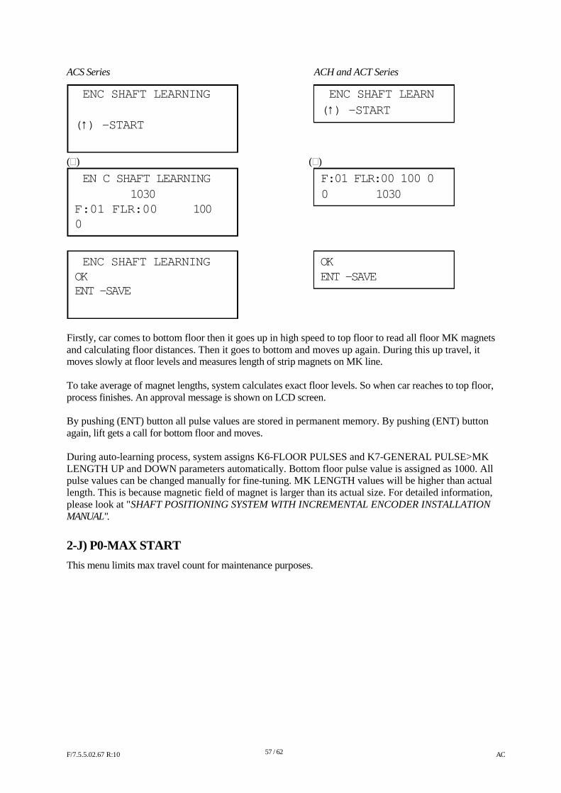
ACS Series
ENC SHAFT LEARNING
(↑) -START
()
EN C SHAFT LEARNING
ACH and ACT Series
ENC SHAFT LEARN
(↑) -START
()
F:01 FLR:00 100 0 1030 0 1030
F:01 FLR:00 100 0 ENC SHAFT LEARNING OK
OK ENT -SAVE ENT -SAVE
Firstly, car comes to bottom floor then it goes up in high speed to top floor to read all floor MK magnets and calculating floor distances. Then it goes to bottom and moves up again. During this up travel, it moves slowly at floor levels and measures length of strip magnets on MK line. To take average of magnet lengths, system calculates exact floor levels. So when car reaches to top floor, process finishes. An approval message is shown on LCD screen. By pushing (ENT) button all pulse values are stored in permanent memory. By pushing (ENT) button again, lift gets a call for bottom floor and moves. During auto-learning process, system assigns K6-FLOOR PULSES and K7-GENERAL PULSE>MK LENGTH UP and DOWN parameters automatically. Bottom floor pulse value is assigned as 1000. All pulse values can be changed manually for fine-tuning. MK LENGTH values will be higher than actual length. This is because magnetic field of magnet is larger than its actual size. For detailed information, please look at "SHAFT POSITIONING SYSTEM WITH INCREMENTAL ENCODER INSTALLATION MANUAL".
2-J) P0-MAX START
This menu limits max travel count for maintenance purposes. F/7.5.5.02.67 R:10
57 / 62
AC
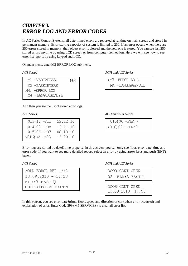
CHAPTER 3:
ERROR LOG AND ERROR CODES In AC Series Control Systems, all determined errors are reported at runtime on main screen and stored in permanent memory. Error storing capacity of system is limited to 250. If an error occurs when there are 250 errors stored in memory, then oldest error is cleared and the new one is stored. You can see last 250 stored errors anytime by using LCD screen or from computer connection. Here we will see how to see error list reports by using keypad and LCD. On main menu, enter M3-ERROR LOG sub-menu. ACS Series
M1 -VARIABLES
M2 -PAREMETERS >M3 -ERROR LOG M4 -LANGUAGE/DiL
M00
ACH and ACT Series
>M3 -ERROR LO G M4 -LANGUAGE/DiL
And then you see the list of stored error logs. ACS Series ACH and ACT Series
013)18 -F11 22.12.10 015)06 -FLR:7
014)03 -F08 12.11.10 >016)02 -FLR:3 015)06 -F07 08.10.10
>016)02 -F03 13.09.10
Error logs are sorted by date&time property. In this screen, you can only see floor, error date, time and error code. If you want to see more detailed report, select an error by using arrow keys and push (ENT) button. ACS Series
/OLD ERROR REP ./#2
13.09.2010 - 17:53
FLR:3 FAST DOOR CONT.ARE OPEN
ACH and ACT Series
DOOR CONT OPEN
02 -FLR:3 FAST DOOR CONT OPEN 13.09.2010 -17:53
In this screen, you see error date&time, floor, speed and direction of car (when error occurred) and explanation of error. Enter Code:399 (M5-SERVICES) to clear all error list. F/7.5.5.02.67 R:10
58 / 62
AC
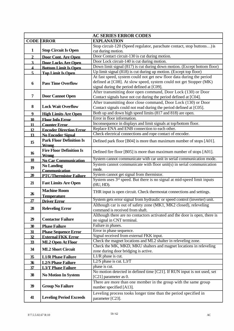
AC SERIES ERROR CODES CODE ERROR EXPLANATION
Stop circuit-120 (Speed regulator, parachute contact, stop buttons…) is 1
2 34 5 6 7 8
9 10 11 12 13
15 16
18
19
20
21 26
27
28 29
30 31 32 33
34
35 36 37
38 39
41
Stop Circuit Is Open
Door Cont. Are Open Door Locks Are Open Bottom Limit Is Open Top Limit Is Open Pass Time Overflow Door Cannot Open Lock Wait Overflow
High Limits Are Open Floor Info Error Counter Error Encoder Direction Error No Encoder Signal Park Floor Definition Is Wrong Fire Floor Definition Is Wrong No Car Communication No Landing Communication PTC/Thermistor Failure
Fast Limits Are Open
Machine Room Temperature Driver Error
Releveling Error Contactor Failure
Phase Failure Phase Sequence Error External FKK Error ML2 Open At Floor
ML2 Short Circuit
L1/R Phase Failure L2/S Phase Failure L3/T Phase Failure
No Motion In System Group No Failure
Leveling Period Exceeds
cut during motion. Door Contact circuit-130 is cut during motion. Door Lock circuit-140 is cut during motion. Down limit signal (817) is cut during down motion. (Except bottom floor) Up limit signal (818) is cut during up motion. (Except top floor) At fast speed, system could not get new floor data during the period defined at [C08]. At slow speed, system could not get Stopper (MK) signal during the period defined at [C09]. After transmitting door open command, Door Lock (130) or Door Contact signals have not cut during the period defined at [C04]. After transmitting door close command, Door Lock (130) or Door Contact signals could not read during the period defined at [C05]. Both up and down high speed limits (817 and 818) are open. Error in floor information. Inconsequence in displays and limit signals at top/bottom floor. Replace ENA and ENB connection to each other. Check electrical connections and rope contact of encoder.
Defined park floor [B04] is more than maximum number of stops [A01]. Defined fire floor [B05] is more than maximum number of stops [A01].
System cannot communicate with car unit in serial communication mode. System cannot communicate with floor unit(s) in serial communication mode. System cannot get signal from thermistor. System uses 3rd speed. But there is no signal at mid-speed limit inputs (HU, HD).
THR input is open circuit. Check thermostat connections and settings.
System gets error signal from hydraulic or speed control (inverter) unit. Although car is out of safety zone (MK1, MK2 closed), releveling command is received from shaft. Although there are no contactors activated and the door is open, there is no signal in CNT terminal. Failure in phases. Error in phase sequence. Signal received from external FKK input. Check the magnet locations and ML2 shalter in releveling zone. Check the MK, MKD, MKU shalters and magnet locations in releveling zone during door bridging is active. L1/R phase is cut. L2/S phase is cut. L3/T phase is cut. No motion detected in defined time [C21]. If RUN input is not used, set [C21] parameter as 0. There are more than one member in the group with the same group number specified [A13]. Leveling process tooks longer time than the period specified in parameter [C23].
F/7.5.5.02.67 R:10
59 / 62
AC
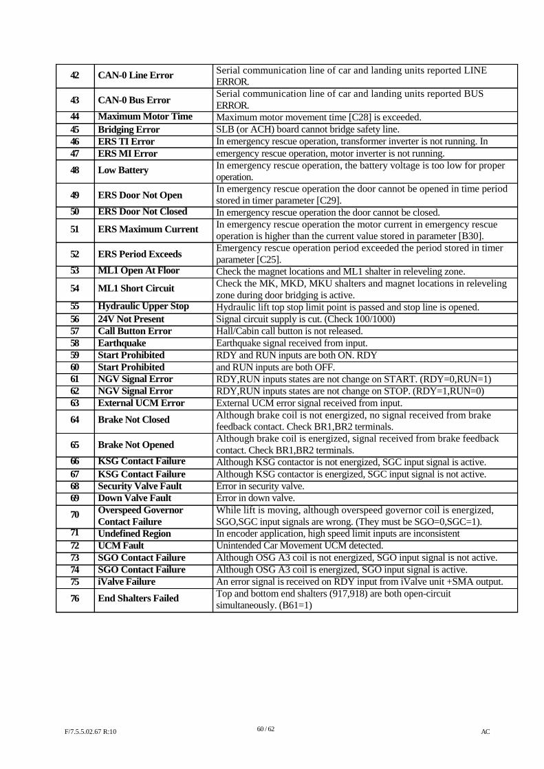
42 43
44 45 46 47
48 49
50
51 52
53
54
55 56 57 58 59 60 61 62 63
64 65
66 67 68 69
70
71 72 73 74 75
76
CAN-0 Line Error CAN-0 Bus Error
Maximum Motor Time Bridging Error ERS TI Error ERS MI Error
Low Battery ERS Door Not Open
ERS Door Not Closed
ERS Maximum Current ERS Period Exceeds
ML1 Open At Floor
ML1 Short Circuit
Hydraulic Upper Stop 24V Not Present Call Button Error Earthquake Start Prohibited Start Prohibited NGV Signal Error NGV Signal Error External UCM Error
Brake Not Closed Brake Not Opened
KSG Contact Failure KSG Contact Failure Security Valve Fault Down Valve Fault Overspeed Governor Contact Failure Undefined Region UCM Fault SGO Contact Failure SGO Contact Failure iValve Failure
End Shalters Failed
Serial communication line of car and landing units reported LINE ERROR. Serial communication line of car and landing units reported BUS ERROR. Maximum motor movement time [C28] is exceeded. SLB (or ACH) board cannot bridge safety line. In emergency rescue operation, transformer inverter is not running. In emergency rescue operation, motor inverter is not running. In emergency rescue operation, the battery voltage is too low for proper operation. In emergency rescue operation the door cannot be opened in time period stored in timer parameter [C29]. In emergency rescue operation the door cannot be closed. In emergency rescue operation the motor current in emergency rescue operation is higher than the current value stored in parameter [B30]. Emergency rescue operation period exceeded the period stored in timer parameter [C25]. Check the magnet locations and ML1 shalter in releveling zone. Check the MK, MKD, MKU shalters and magnet locations in releveling zone during door bridging is active. Hydraulic lift top stop limit point is passed and stop line is opened. Signal circuit supply is cut. (Check 100/1000) Hall/Cabin call button is not released. Earthquake signal received from input. RDY and RUN inputs are both ON. RDY and RUN inputs are both OFF. RDY,RUN inputs states are not change on START. (RDY=0,RUN=1) RDY,RUN inputs states are not change on STOP. (RDY=1,RUN=0) External UCM error signal received from input. Although brake coil is not energized, no signal received from brake feedback contact. Check BR1,BR2 terminals. Although brake coil is energized, signal received from brake feedback contact. Check BR1,BR2 terminals. Although KSG contactor is not energized, SGC input signal is active. Although KSG contactor is energized, SGC input signal is not active. Error in security valve. Error in down valve. While lift is moving, although overspeed governor coil is energized, SGO,SGC input signals are wrong. (They must be SGO=0,SGC=1). In encoder application, high speed limit inputs are inconsistent Unintended Car Movement UCM detected. Although OSG A3 coil is not energized, SGO input signal is not active. Although OSG A3 coil is energized, SGO input signal is active. An error signal is received on RDY input from iValve unit +SMA output. Top and bottom end shalters (917,918) are both open-circuit simultaneously. (B61=1)
F/7.5.5.02.67 R:10
60 / 62
AC
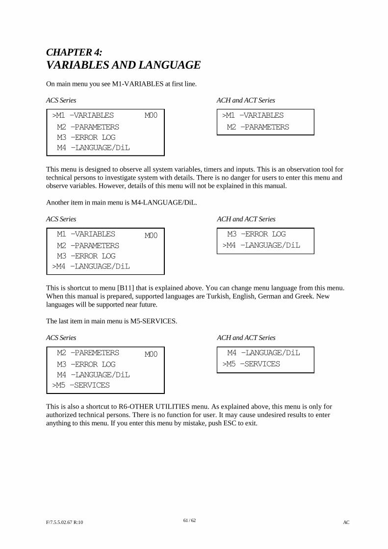
CHAPTER 4:
VARIABLES AND LANGUAGE On main menu you see M1-VARIABLES at first line. ACS Series ACH and ACT Series
>M1 -VARIABLES M00 >M1 -VARIABLES
M2 -PARAMETERS M2 -PARAMETERS M3 -ERROR LOG M4 -LANGUAGE/DiL
This menu is designed to observe all system variables, timers and inputs. This is an observation tool for technical persons to investigate system with details. There is no danger for users to enter this menu and observe variables. However, details of this menu will not be explained in this manual. Another item in main menu is M4-LANGUAGE/DiL. ACS Series
M1 -VARIABLES M2 -PARAMETERS M3 -ERROR LOG
>M4 -LANGUAGE/DiL
M00
ACH and ACT Series
M3 -ERROR LOG >M4 -LANGUAGE/DiL
This is shortcut to menu [B11] that is explained above. You can change menu language from this menu. When this manual is prepared, supported languages are Turkish, English, German and Greek. New languages will be supported near future. The last item in main menu is M5-SERVICES. ACS Series
M2 -PAREMETERS M3 -ERROR LOG M4 -LANGUAGE/DiL
>M5 -SERVICES
M00
ACH and ACT Series
M4 -LANGUAGE/DiL
>M5 -SERVICES
This is also a shortcut to R6-OTHER UTILITIES menu. As explained above, this menu is only for authorized technical persons. There is no function for user. It may cause undesired results to enter anything to this menu. If you enter this menu by mistake, push ESC to exit. F/7.5.5.02.67 R:10
61 / 62
AC
CHAPTER 5:
UCM SERVICE M6-UCM SERVICE menu is used for EN 81-1/2+ A3 norm related functions. 5-A) U1-CLEAR ERROR This menu is used to clear UCM Errors (Error 64 and Error 72) that caused the system to be blocked. Before clearing the error and removing the blockage, the reason of error must be detected and removed. Error clearing must be performed by only competent person.
5-B) U2-UCM TEST ( SLB4 board is required for ACT/ACS Series) This utility starts Manual UCM Test procedure for Gearless systems and Valve Test procedure for Hydraulic systems.
5-C) U3-TEST TIME This parameter defines the start date and time for periodic Automatic Test Procedure according to EN 81-1/2+A3 norm. It is active only when parameter B59=2 (Daily Check) and RTC is installed. After completing autotest, the test date is automatically assigned to the next day.
5-D) U4-TEST START This parameter defines the number of start period of Automatic Test Procedure according to EN81-1/2+A3 norm. When the number of start value reaches the multiples of this period, Automatic test is started. It is active only when parameter B59=1 (Start Count) and can be set between 2 and 1500. 5-E) U5 -TEST COUNTER Actual number of starts passing after the last Autotest is counted in this parameter for monitoring purposes. F/7.5.5.02.67 R:10
62 / 62
AC