Embed Size (px)
Citation preview
Sludge Management EENV 5000
Chapter 5
Sludge Thickening and Dewatering
2
Preliminary Considerations
Thickening and dewatering are covered together in
this chapter since both of them have the same
objective of reducing the water content in the sludge to
reduce the sludge volume.
Conditioning is also covered since its objective is to
improve water removal and solids capture.
3
This chapter covers the following topics:
Introductory aspects
Sludge thickening
Gravity thickeners
Dissolved air flotation
thickeners
Sludge conditioning
Introductory aspects
Organic polymers
Inorganic chemical
conditioning
Sludge dewatering
Introductory aspects
Sludge drying beds
Centrifuges
Filter presses
Belt presses
4
Water in Sludge
Water removal takes place in the thickening and
dewatering stages.
Sludge thickening:
is mainly used in primary treatment, activated sludge, and
trickling filter processes.
Has large implications on the design and operation of sludge
digesters.
Sludge dewatering:
Carried out in digested sludge
Impacts sludge transportation and final disposal costs.
Main reasons for dewatering are listed in the next slide:
5
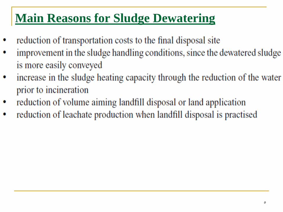
Main Reasons for Sludge Dewatering
6
…standard error
The standard error provides an indication of the
accuracy of the point estimate. Smaller values of the
standard error indicate that the point estimate is likely
to be more accurate because its variability about the
true value is smaller.
7
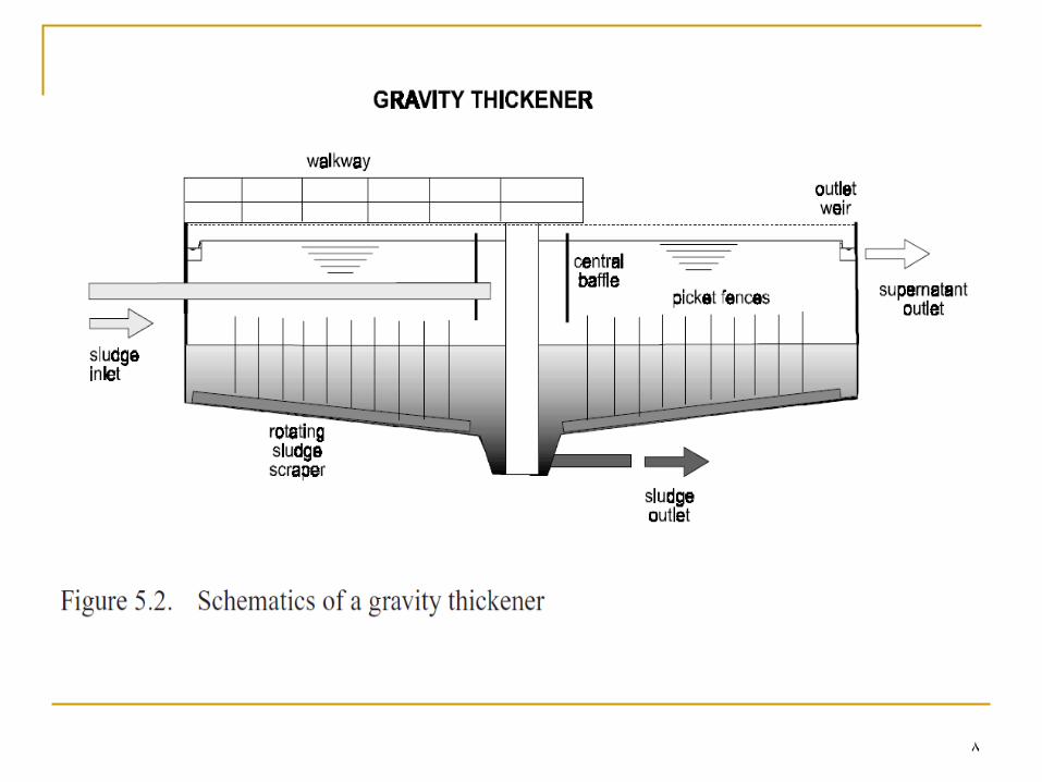
A. Gravity Thickeners
Similar to settling tanks.
Tank is circular with central feeding (next slide)
The thickened sludge exists from the bottom to the next
stage (normally digestion).
The supernatant exits from the sides to be returned to
the head of the works
8
9
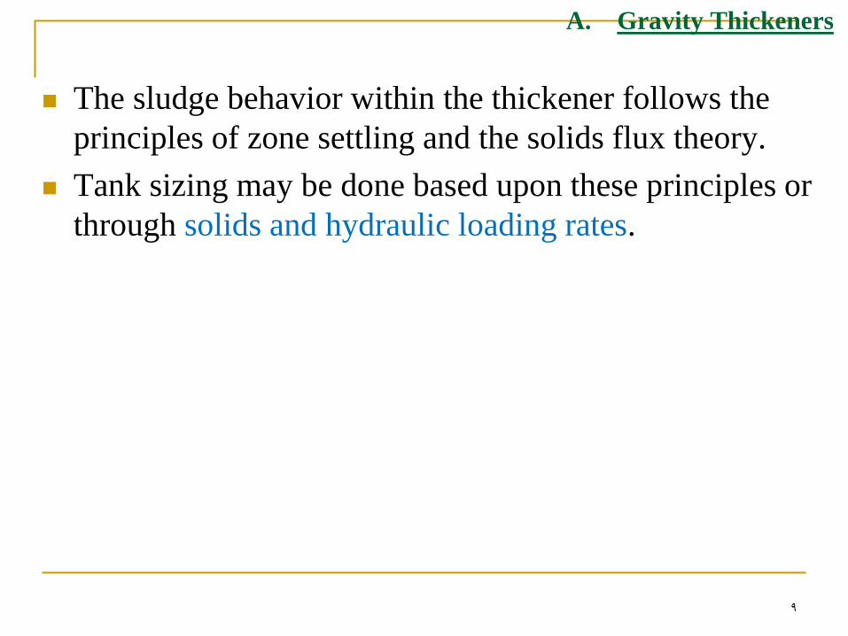
A. Gravity Thickeners
The sludge behavior within the thickener follows the
principles of zone settling and the solids flux theory.
Tank sizing may be done based upon these principles or
through solids and hydraulic loading rates.
10
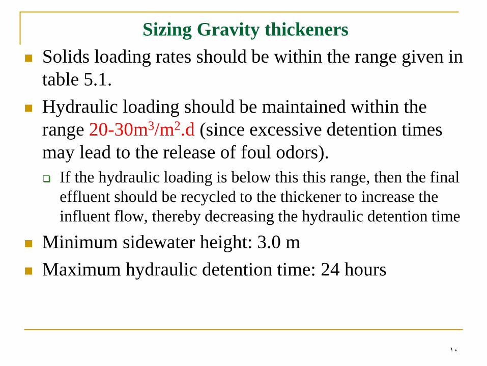
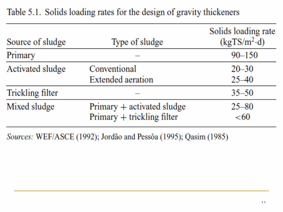
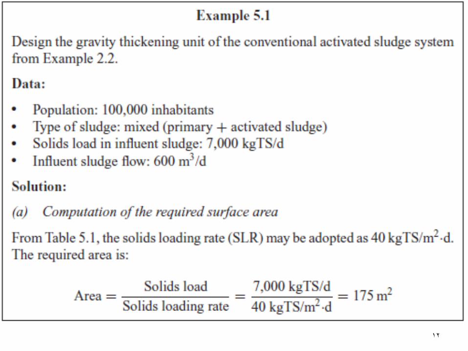
Sizing Gravity thickeners
Solids loading rates should be within the range given in
table 5.1.
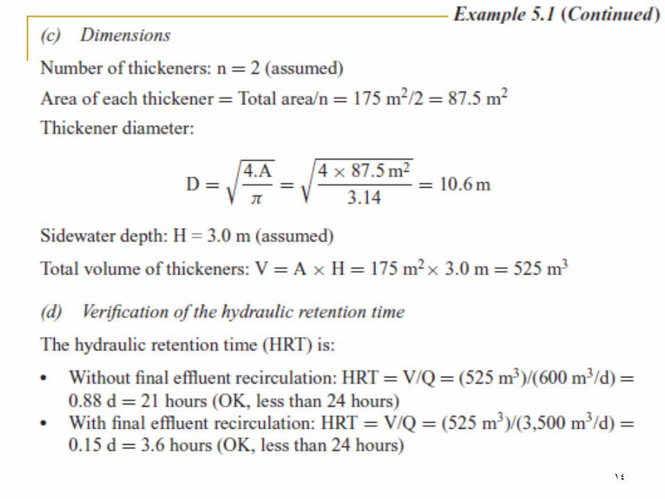
Hydraulic loading should be maintained within the
range 20-30m3/m2.d (since excessive detention times
may lead to the release of foul odors).
If the hydraulic loading is below this this range, then the final
effluent should be recycled to the thickener to increase the
influent flow, thereby decreasing the hydraulic detention time
Minimum sidewater height: 3.0 m
Maximum hydraulic detention time: 24 hours
11
12

13
14
15
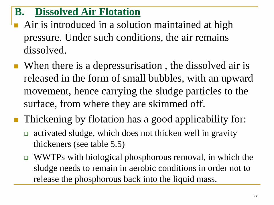
B. Dissolved Air Flotation
Air is introduced in a solution maintained at high
pressure. Under such conditions, the air remains
dissolved.
When there is a depressurisation , the dissolved air is
released in the form of small bubbles, with an upward
movement, hence carrying the sludge particles to the
surface, from where they are skimmed off.
Thickening by flotation has a good applicability for:
activated sludge, which does not thicken well in gravity
thickeners (see table 5.5)
WWTPs with biological phosphorous removal, in which the
sludge needs to remain in aerobic conditions in order not to
release the phosphorous back into the liquid mass.
16
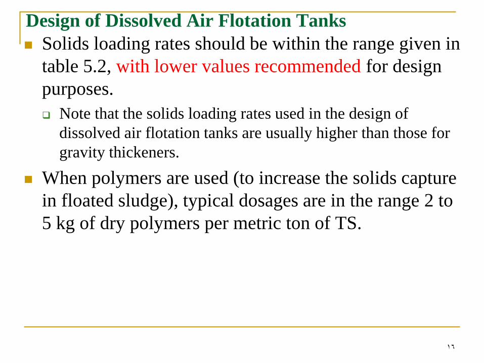
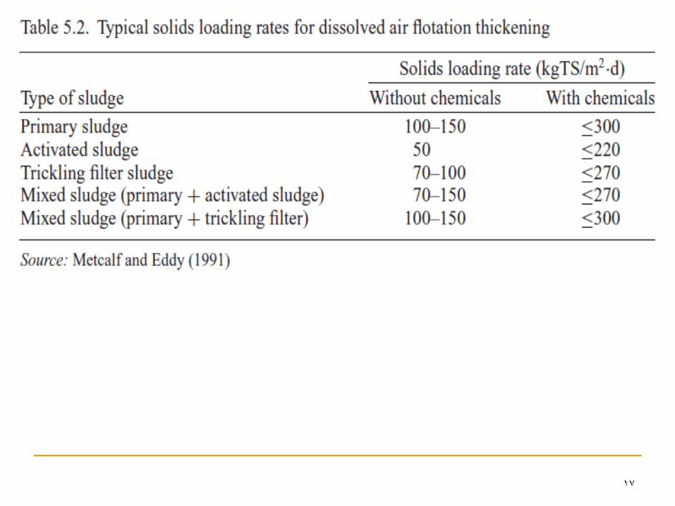
Design of Dissolved Air Flotation Tanks
Solids loading rates should be within the range given in
table 5.2, with lower values recommended for design
purposes.
Note that the solids loading rates used in the design of
dissolved air flotation tanks are usually higher than those for
gravity thickeners.
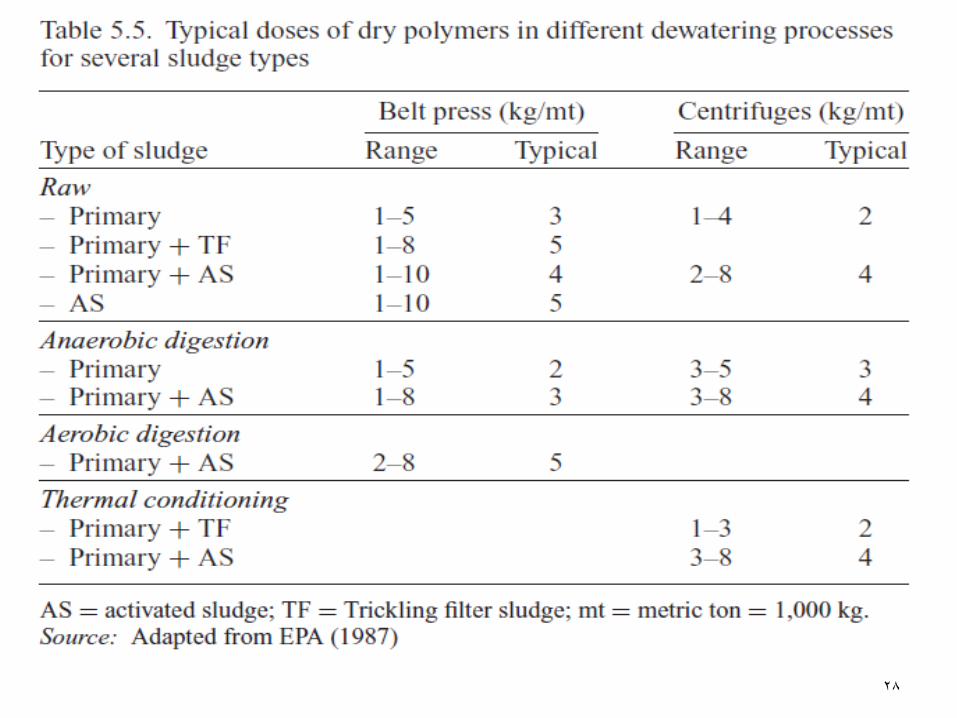
When polymers are used (to increase the solids capture
in floated sludge), typical dosages are in the range 2 to
5 kg of dry polymers per metric ton of TS.
17

18
Sludge Conditioning
Conditioning is a sludge preparation process aiming at
increasing its dewatering capability and improving the
capture of solids in the sludge dewatering systems.
The chemical products are applied to the sludge upstream
of the dewatering unit, favouring the aggregation of the
solids particles and the formation of flocs.
The conditioning can also be employed upstream of the
mechanised thickening units.
The conditioning can be accomplished using: (table 5.3)
Inorganic chemicals
Organic chemicals
Thermal treatment

19

20
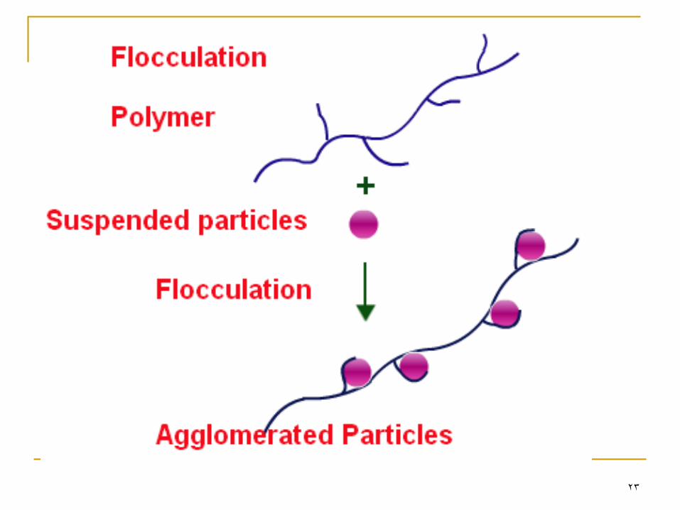
Conditioning increases particle sizes, entrapping the
small particles into larger flocs.
This is accomplished through coagulation followed by
flocculation.
Coagulation: destabilises the particles, decreasing the intensity
of the electrostatic repulsion forces among them, and therefore
facilitating the mutual attraction.
Flocculation: allows the agglomeration of colloids and thin
solids through low mixing gradients.
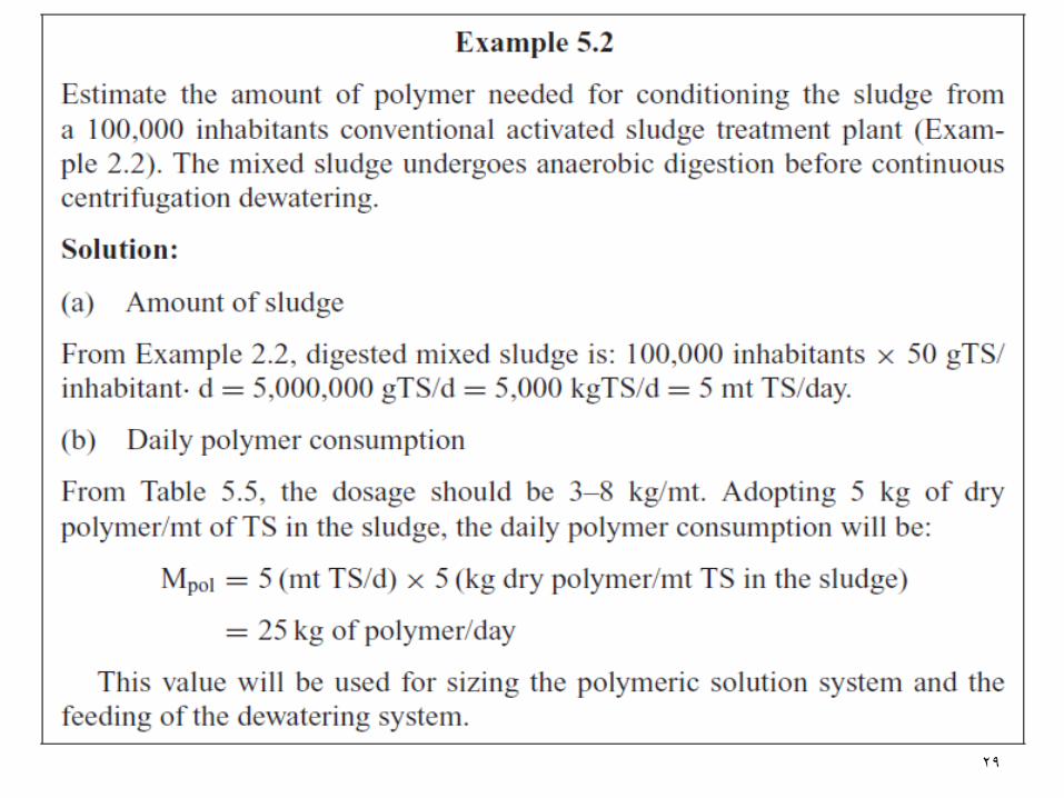
The amount of conditioning product to be used may vary
with the sludge characteristics and the dewatering
equipment adopted.
21
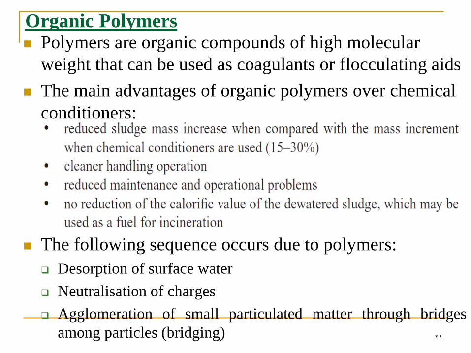
Organic Polymers Polymers are organic compounds of high molecular
weight that can be used as coagulants or flocculating aids
The main advantages of organic polymers over chemical
conditioners:
The following sequence occurs due to polymers:
Desorption of surface water
Neutralisation of charges
Agglomeration of small particulated matter through bridges
among particles (bridging)
22
…Organic Polymers
Polymers are made up of long chains of special chemical
elements soluble in water.
Polymers can be:
Neutral (non-ionic)
cationic
Anionic
Polymers used for sludge conditioning are usually
cationic since most sludges have predominantly negative
electric charges.
Polymers are found in 1) powder, or 2) liquid form.
1- Dry polymers can be stored for several years.
2- Liquid polymers have storage periods from 6 to 12 months.
23
24
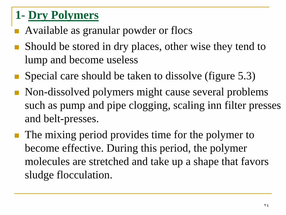
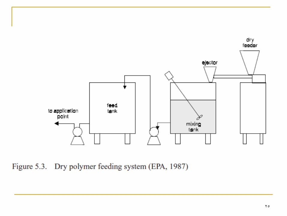
1- Dry Polymers
Available as granular powder or flocs
Should be stored in dry places, other wise they tend to
lump and become useless
Special care should be taken to dissolve (figure 5.3)
Non-dissolved polymers might cause several problems
such as pump and pipe clogging, scaling inn filter presses
and belt-presses.
The mixing period provides time for the polymer to
become effective. During this period, the polymer
molecules are stretched and take up a shape that favors
sludge flocculation.
25
26
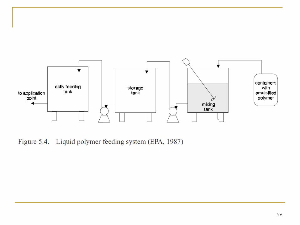
2- Liquid Polymers
Available in different concentrations
The preparation of the dosing solution is constituted of a
mixing tank and a storage tank for the diluted polymer
(figure 5.4).
Normally a 0.1% polymer solution is produced by mixing
a concentrated polymer solution and water for at least 30
minutes.
27
28
29
30
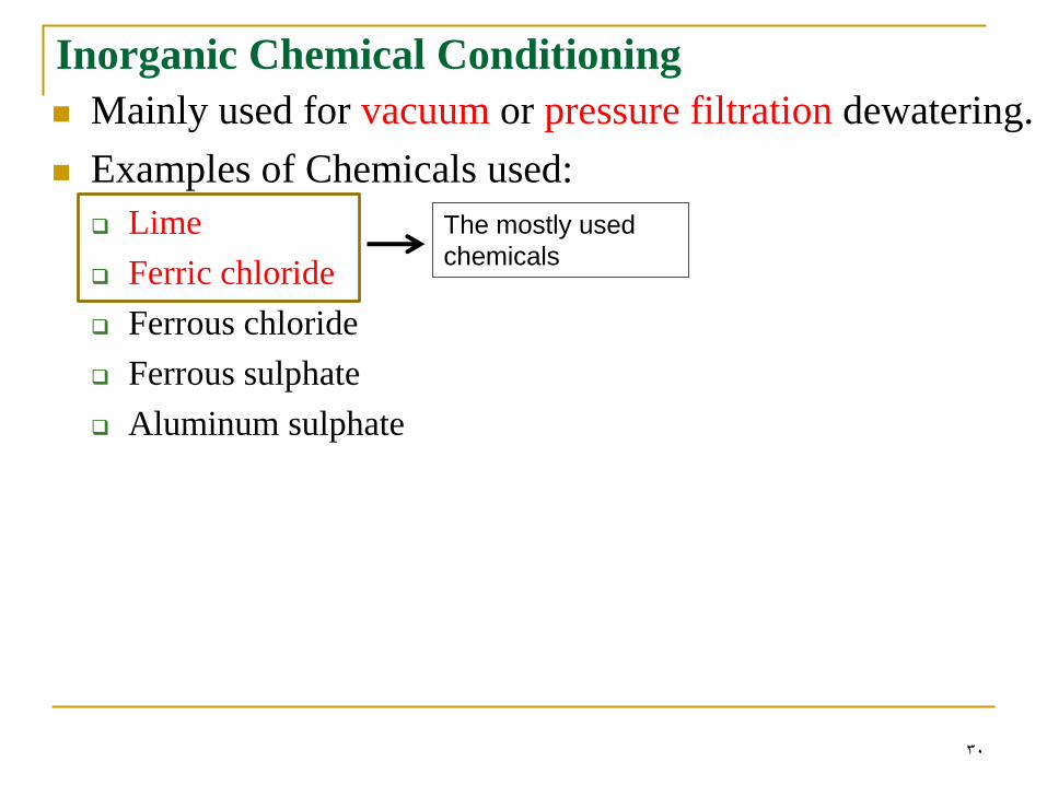
Inorganic Chemical Conditioning
Mainly used for vacuum or pressure filtration dewatering.
Examples of Chemicals used:
Lime
Ferric chloride
Ferrous chloride
Ferrous sulphate
Aluminum sulphate
The mostly used
chemicals
31
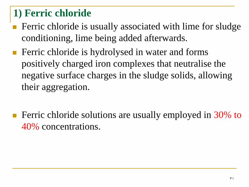
1) Ferric chloride
Ferric chloride is usually associated with lime for sludge
conditioning, lime being added afterwards.
Ferric chloride is hydrolysed in water and forms
positively charged iron complexes that neutralise the
negative surface charges in the sludge solids, allowing
their aggregation.
Ferric chloride solutions are usually employed in 30% to
40% concentrations.
32
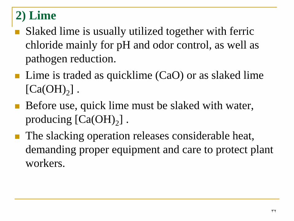
2) Lime
Slaked lime is usually utilized together with ferric
chloride mainly for pH and odor control, as well as
pathogen reduction.
Lime is traded as quicklime (CaO) or as slaked lime
[Ca(OH)2] .
Before use, quick lime must be slaked with water,
producing [Ca(OH)2] .
The slacking operation releases considerable heat,
demanding proper equipment and care to protect plant
workers.
33
Video material on Lime slaking
http://www.youtube.com/watch?v=UXO0l5_4Eqw
http://www.youtube.com/watch?v=eSKX0gzESwI
34
35
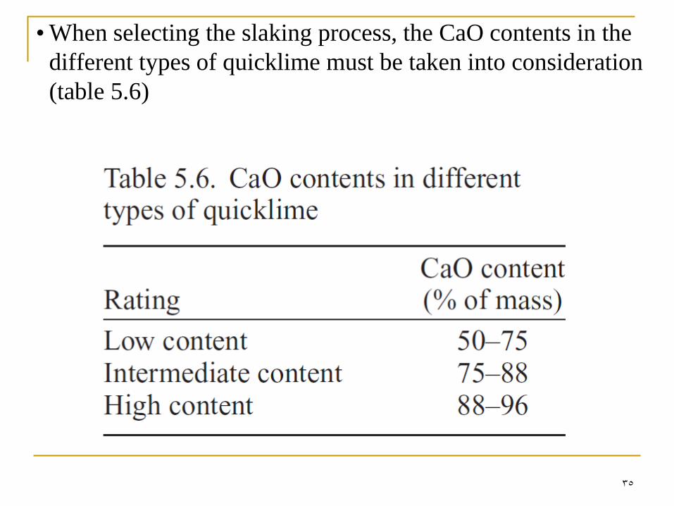
• When selecting the slaking process, the CaO contents in the
different types of quicklime must be taken into consideration
(table 5.6)
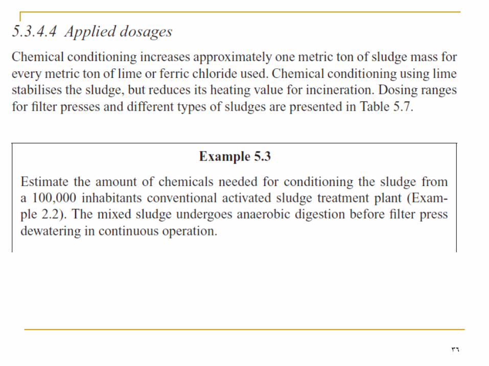
36
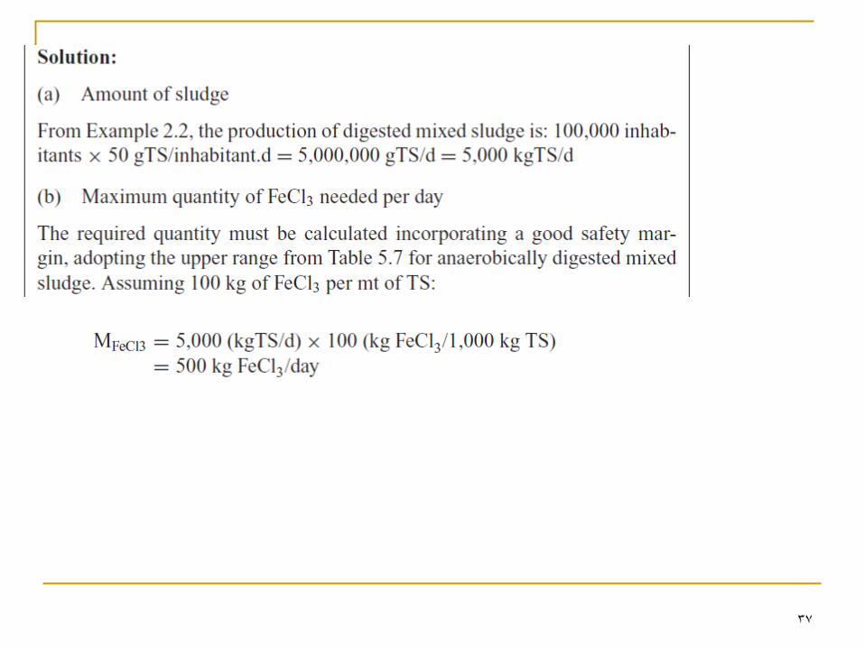
37
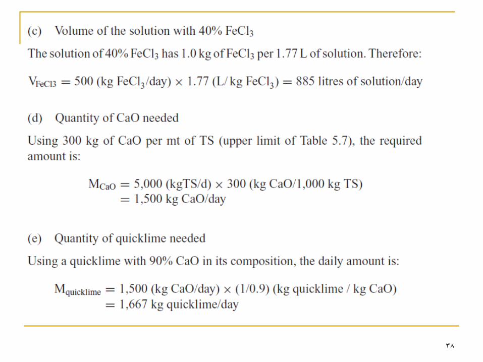
38
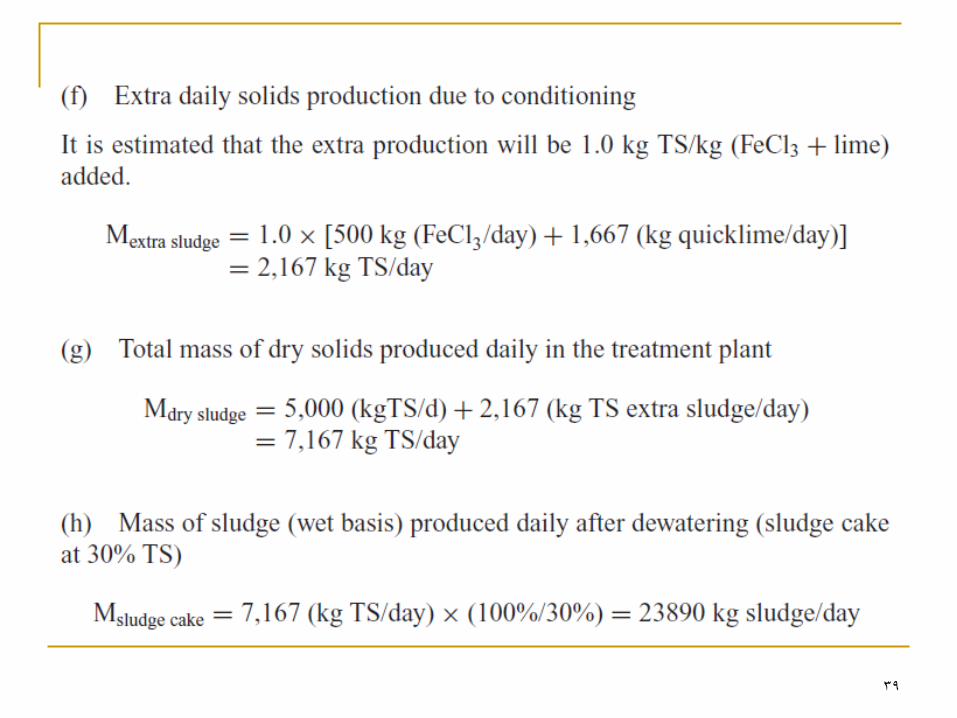
39
40
Sludge Dewatering (sec. 5.4) The main processes used for sludge dewatering are:
Drying beds
Sludge lagoons
Filter press
Centrifuges
Belt filter press
Vacuum filter
Thermal drying
41
42
43
44
Sludge Drying Beds (sec. 5.5)
Water is removed by evaporation & percolation.
The process consists of a tank, usually rectangular, of
masonry or concrete walls and a concrete floor.
These beds are especially popular in small plants
because of their simplicity of operation & maintenance.
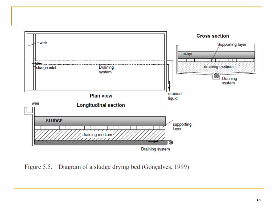
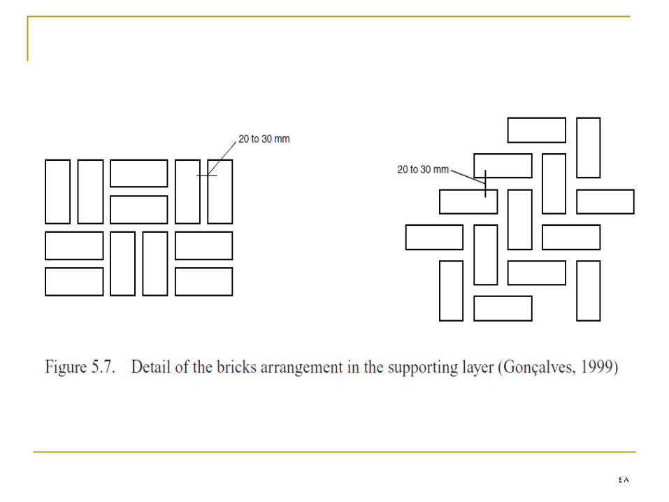
The following elements exist in the tank:
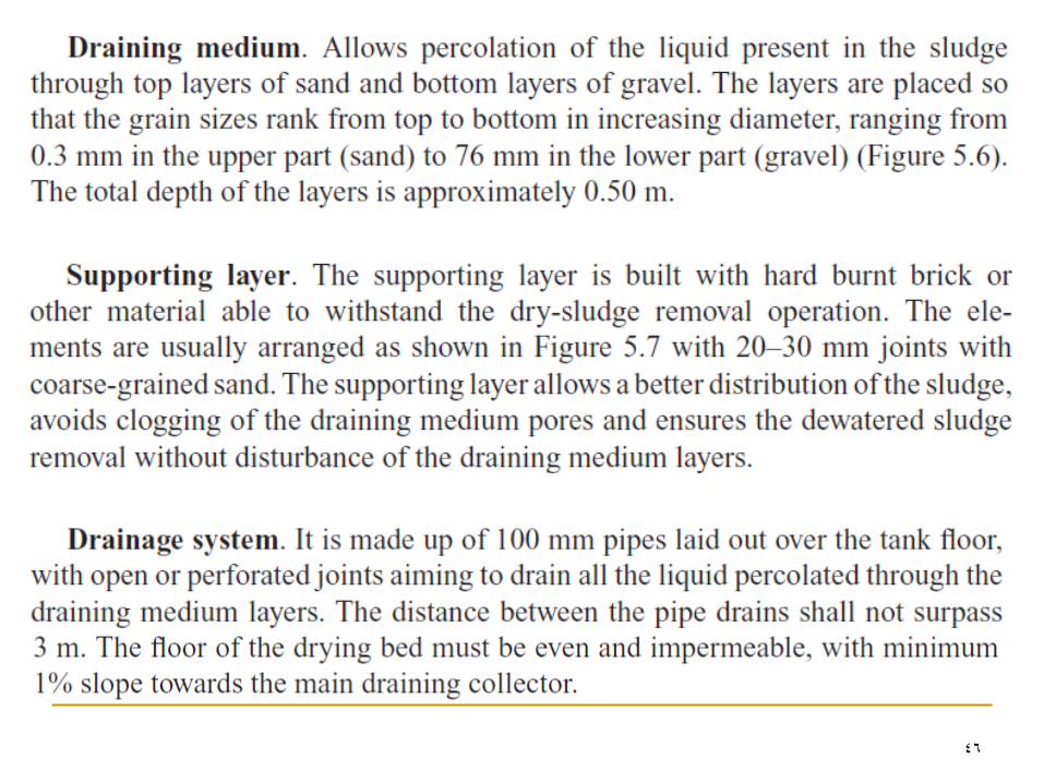
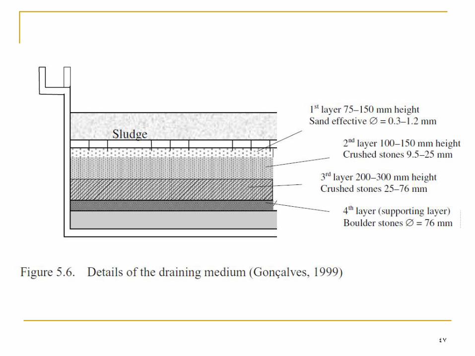
Draining medium
Supporting layer
Draining system
45
46
47
48
49
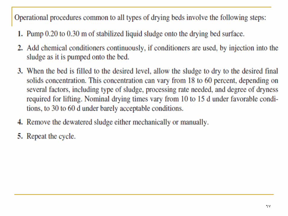
General aspects of Sludge Dewatering in Drying Beds
(sec. 5.5.2)
Well digested sludge has satisfactory characteristics
when subjected to natural drying (the process will occur
in a short period of time).
Sludge drying beds may be open-air constructions or
covered for protection against rainfall.
Drying is taken as a batch process.
During most of the dewatering period, the water
percolates easily through the draining bed, up to the
moment when the sludge deposits itself and changes
into a thick pasty mass. From this point on, the
percolation virtually ends and drying is achieved
through natural evaporation
50
51
52
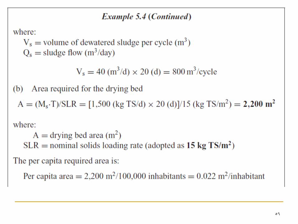
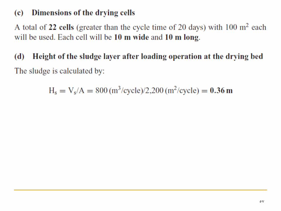
Design of Drying Beds
a) Design based on loading rates
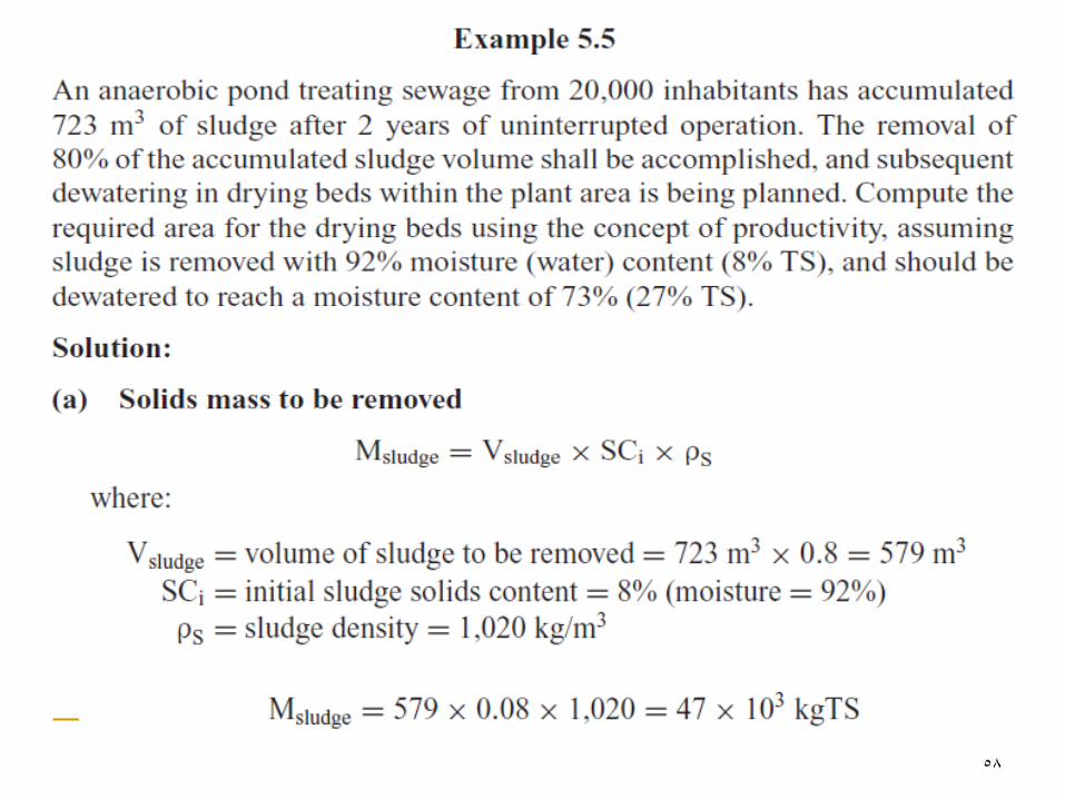
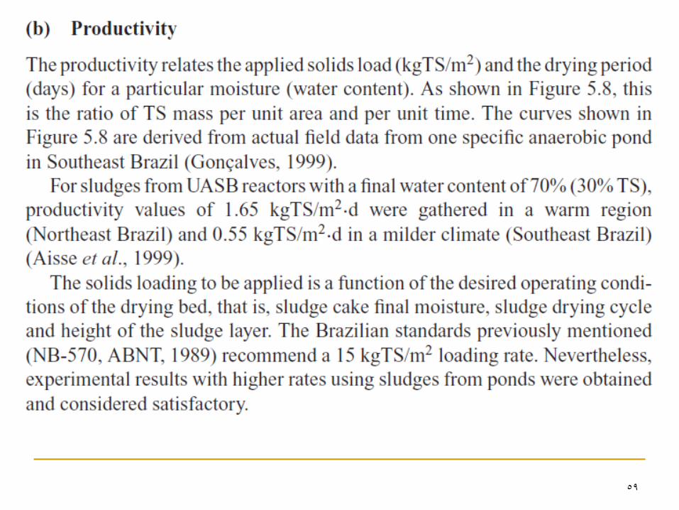
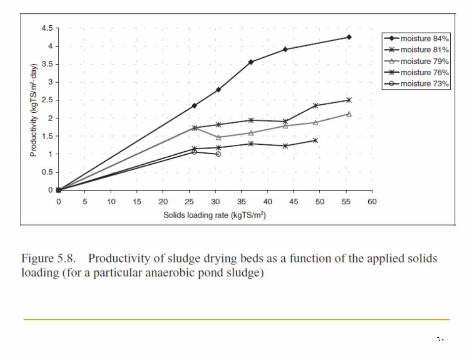
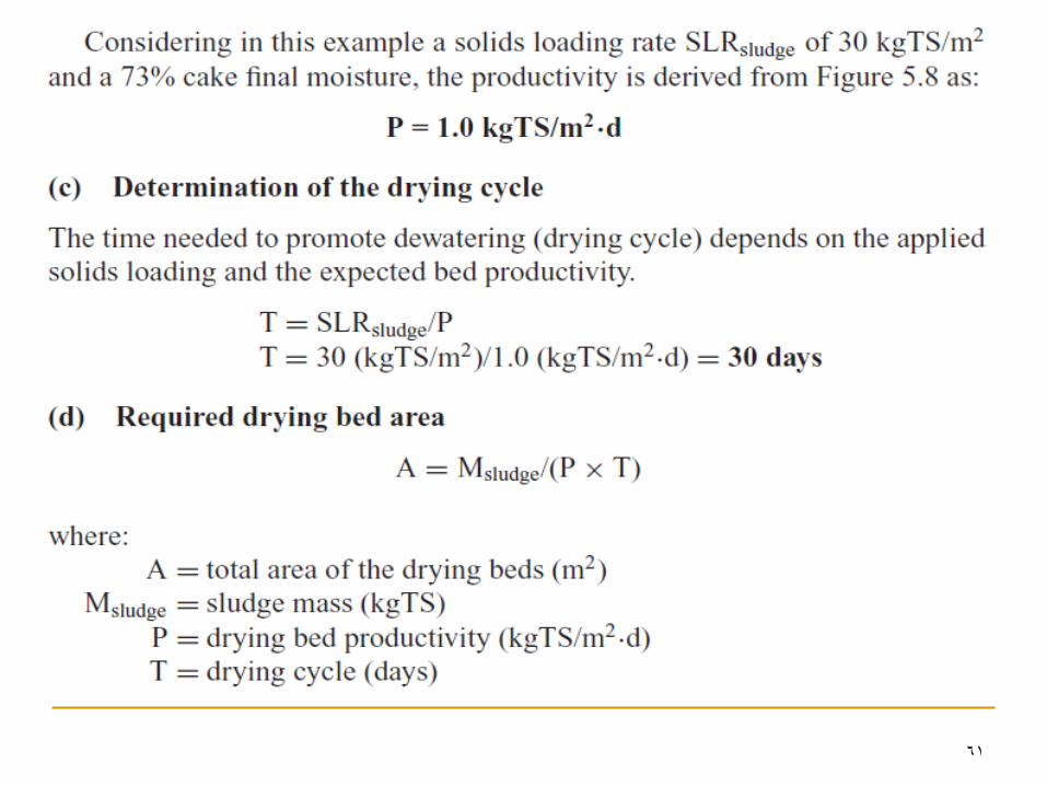
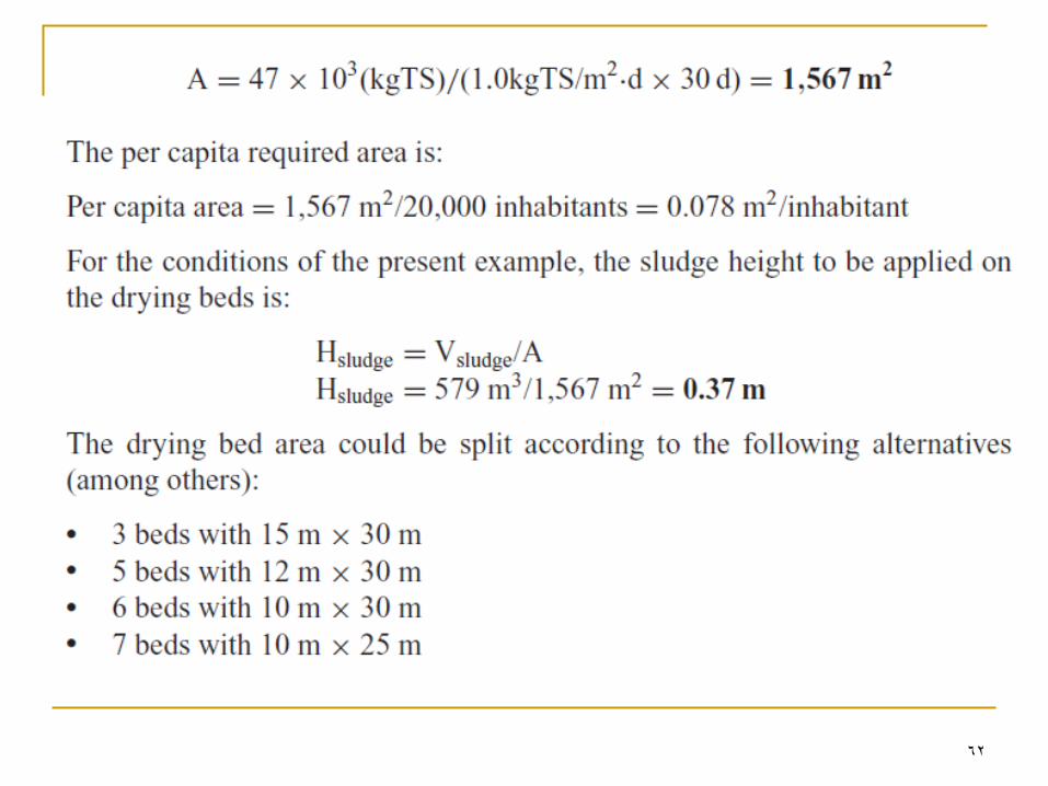
b) Design based on the concept of productivity
53
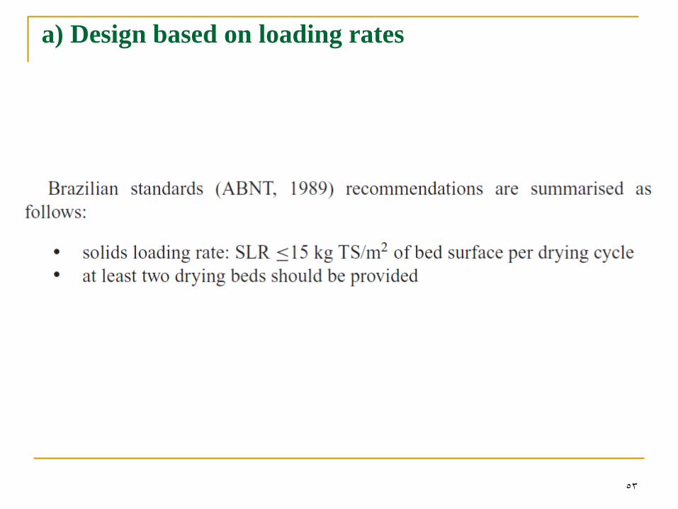
a) Design based on loading rates
54
55
56
57
58
59
60
61
62
63
64
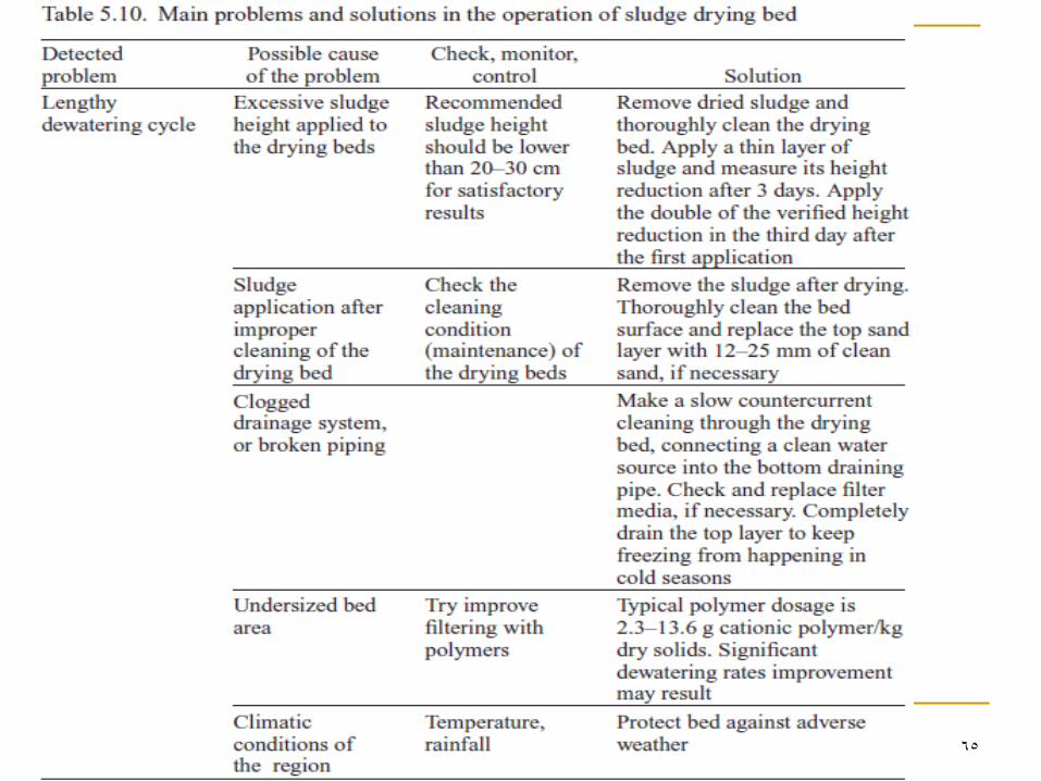
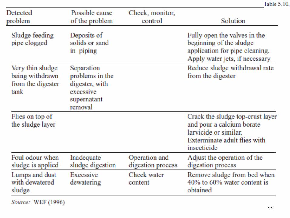
Operational Aspects in Sludge Drying Beds
Table 5.10 presents some operational measures for the
solution of drying bed problems.
65
66
67
68
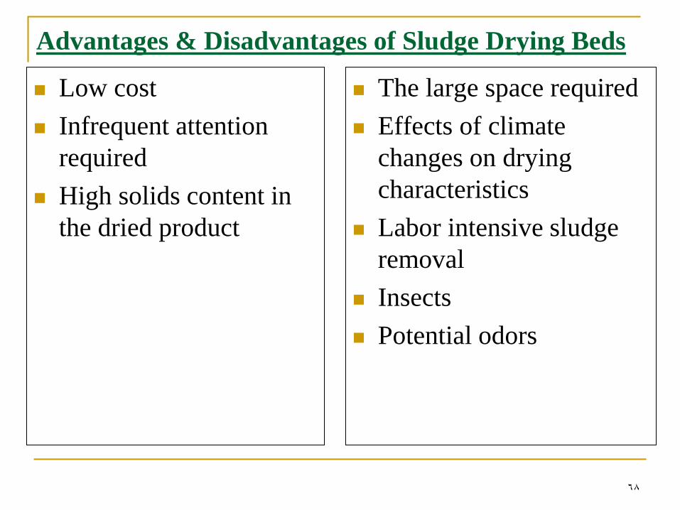
Advantages & Disadvantages of Sludge Drying Beds
Low cost
Infrequent attention
required
High solids content in
the dried product
The large space required
Effects of climate
changes on drying
characteristics
Labor intensive sludge
removal
Insects
Potential odors
69
HW:
There are several types of sludge drying beds? List
five of them and describe each type.
70
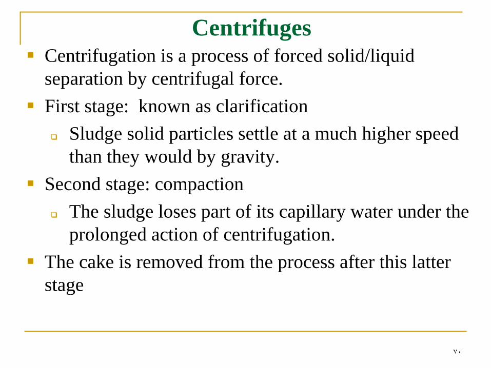
Centrifuges Centrifugation is a process of forced solid/liquid
separation by centrifugal force.
First stage: known as clarification
Sludge solid particles settle at a much higher speed
than they would by gravity.
Second stage: compaction
The sludge loses part of its capillary water under the
prolonged action of centrifugation.
The cake is removed from the process after this latter
stage
71
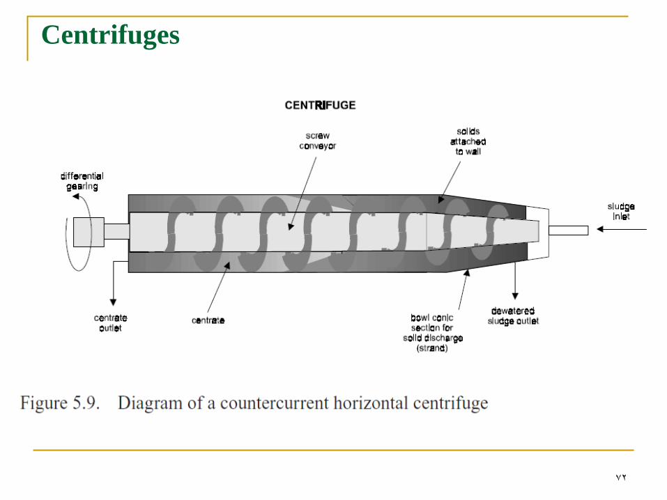
Centrifuges
72
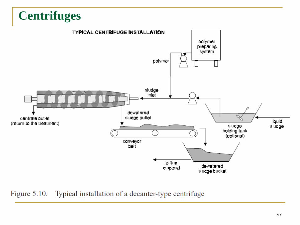
Centrifuges
73
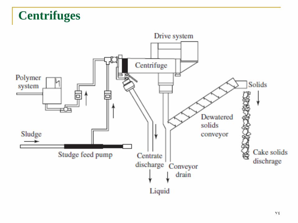
Centrifuges
74
Centrifuges
75
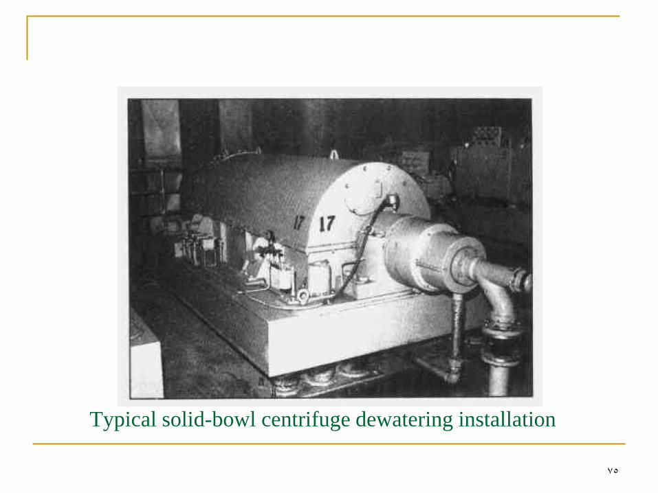
Typical solid-bowl centrifuge dewatering installation
76
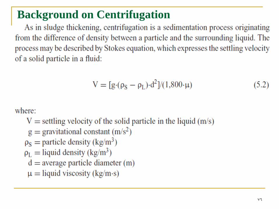
Background on Centrifugation
77
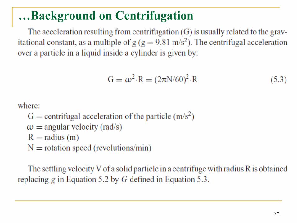
…Background on Centrifugation
78
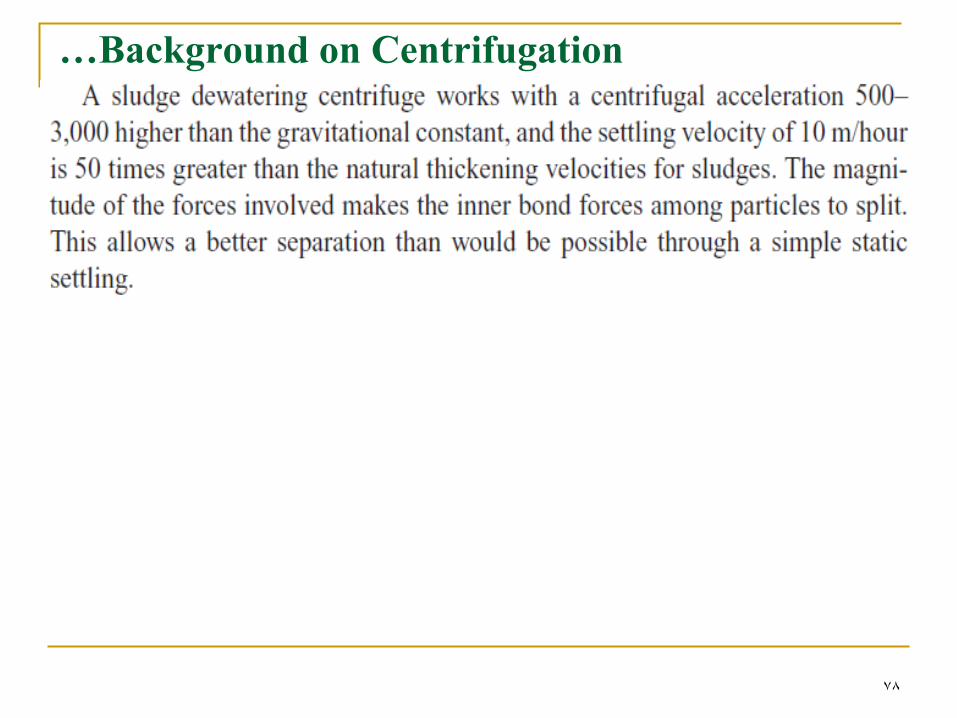
…Background on Centrifugation
79
Centrifuges
Centrifuges may be used indistinctly for sludge
thickening and dewatering,
may install centrifuges in series, with thickening being
accomplished in the first stage and dewatering in the
following one.
Vertical & horizontal shafts
The horizontal is more common
Since the vertical shaft centrifuges have the
disadvantages of producing lower cake solids contents
and the need to feed semi-continuously.
80
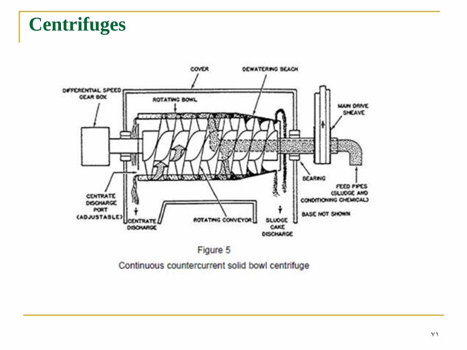
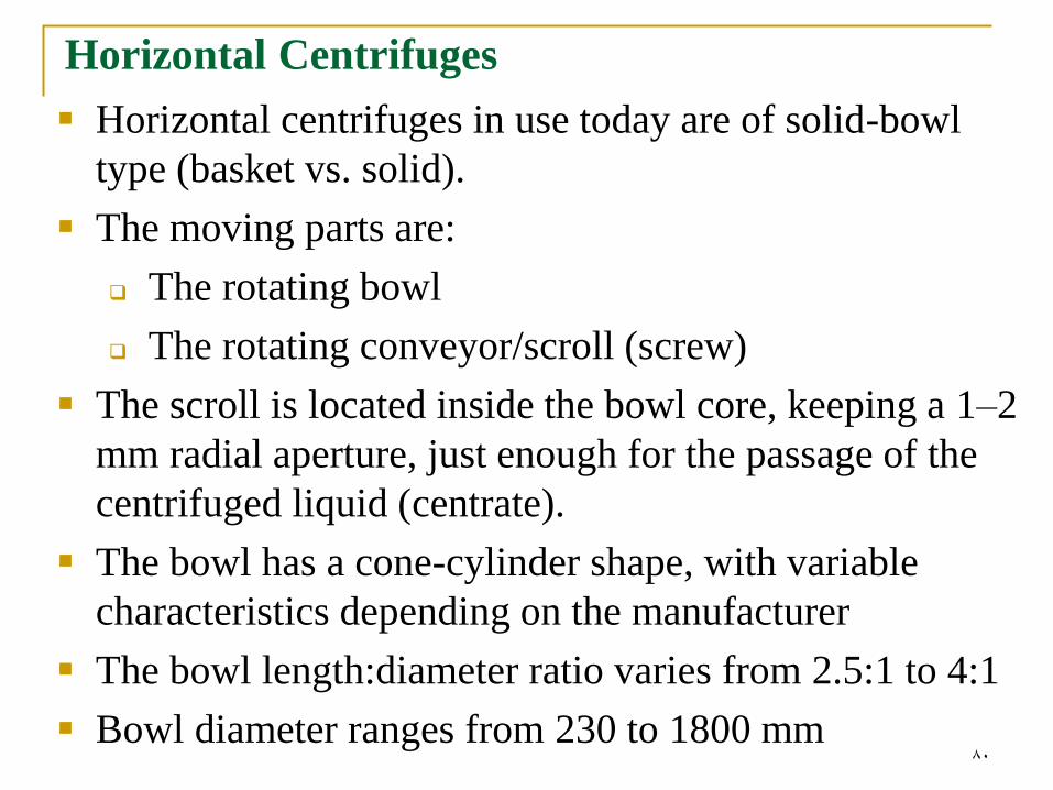
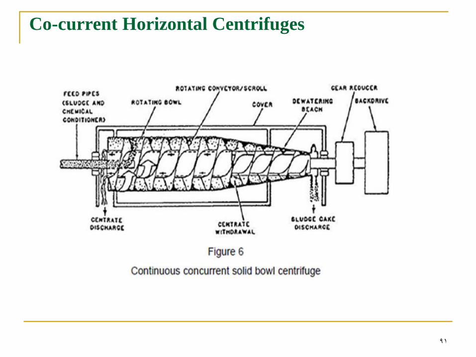
Horizontal Centrifuges
Horizontal centrifuges in use today are of solid-bowl
type (basket vs. solid).
The moving parts are:
The rotating bowl
The rotating conveyor/scroll (screw)
The scroll is located inside the bowl core, keeping a 1–2
mm radial aperture, just enough for the passage of the
centrifuged liquid (centrate).
The bowl has a cone-cylinder shape, with variable
characteristics depending on the manufacturer
The bowl length:diameter ratio varies from 2.5:1 to 4:1
Bowl diameter ranges from 230 to 1800 mm
81
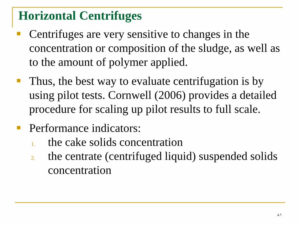
Horizontal Centrifuges
Centrifuges are very sensitive to changes in the
concentration or composition of the sludge, as well as
to the amount of polymer applied.
Thus, the best way to evaluate centrifugation is by
using pilot tests. Cornwell (2006) provides a detailed
procedure for scaling up pilot results to full scale.
Performance indicators:
1. the cake solids concentration
2. the centrate (centrifuged liquid) suspended solids
concentration
82
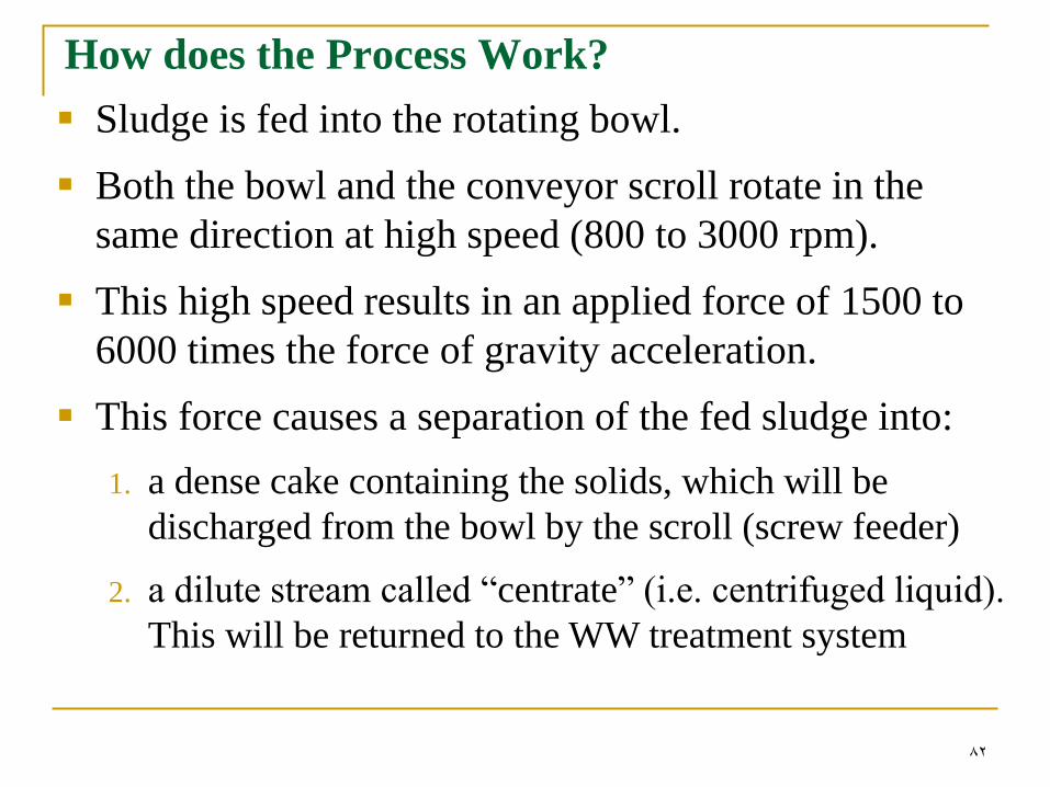
How does the Process Work?
Sludge is fed into the rotating bowl.
Both the bowl and the conveyor scroll rotate in the
same direction at high speed (800 to 3000 rpm).
This high speed results in an applied force of 1500 to
6000 times the force of gravity acceleration.
This force causes a separation of the fed sludge into:
1. a dense cake containing the solids, which will be
discharged from the bowl by the scroll (screw feeder)
2. a dilute stream called “centrate” (i.e. centrifuged liquid).
This will be returned to the WW treatment system
83
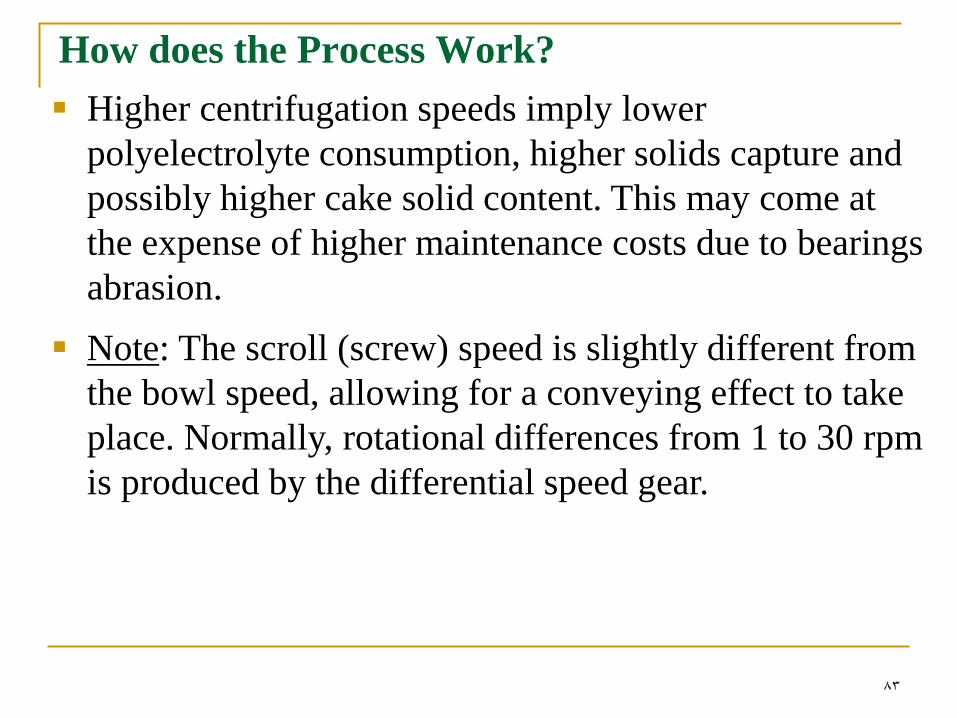
How does the Process Work?
Higher centrifugation speeds imply lower
polyelectrolyte consumption, higher solids capture and
possibly higher cake solid content. This may come at
the expense of higher maintenance costs due to bearings
abrasion.
Note: The scroll (screw) speed is slightly different from
the bowl speed, allowing for a conveying effect to take
place. Normally, rotational differences from 1 to 30 rpm
is produced by the differential speed gear.
84
Horizontal Centrifuges Performance
High solids cakes result from high retention time inside
the centrifuge
The solids retention time is mainly controlled by the
following parameters:
Sludge feeding rate
The speed difference
The bowl rotational speed
Generally, dryer cakes are obtained by:
Minimizing the speed difference between the bowl
and the screw conveyor.
Increasing the bowl rotational speed.
Using a compatible sludge feeding rate.
85
Horizontal Centrifuges Performance
The major difficulty encountered in the operation of
centrifuges has been the disposal of the centrate, which
can be relatively high in suspended, nonsettling solids.
Two methods can be used to control the fine solids
discharge and to increase the capture:
1. Increase the residence time
2. Use chemical conditioning
Longer residence time is accomplished by reducing the
feed rate or by using a centrifuge with a larger bowl
volume
86
Horizontal Centrifuges Performance
The main variables influencing centrifuge performance
are:
1. Sludge solids concentration
2. Type of conditioning
3. Feed flow
4. Temperature
Larger particles are easily captured by the centrifuge,
while finer particles require conditioning to reach a
sufficient size for capture.
High sludge stabilisation levels improve centrifuge
performance, allowing high cake solids content.

87
Horizontal Centrifuges Performance
The main variables influencing centrifuge performance
are:
1. Sludge solids concentration
2. Type of conditioning
3. Feed flow
4. Temperature
Larger particles are easily captured by the centrifuge,
while finer particles require conditioning to reach a
sufficient size for capture.
High sludge stabilisation levels improve centrifuge
performance, allowing high cake solids content.

88
Effectiveness of Polyelectrolytes (polymers)
The effectiveness of chemicals such as
polyelectorolytes is more closely related with the solids
concentration of the centrate (solids capture) than with
the cake solids content.
Cationic polyelectrolyte is often used as a flocculation
aid, giving better solids capture and greater feed flow.
89
Co-current vs. counter-current Horizontal Centrifuges
Horizontal centrifuges may be classified according to
the direction of the feeding flow and the way the cake is
withdrawn into two types:
1. Co-current horizontal centrifuges
2. Counter-current horizontal centrifuges

90
Counter-current Horizontal Centrifuges
91
Co-current Horizontal Centrifuges
92
Other Centrifuge Considerations
Centrifuges are often located on upper floors of the
sludge building so that the cake may be discharged into
trucks or hoppers below.
Because of the mass and vibration of the centrifuge,
special attention should be given to the structural
requirements to handle the load and vibration in
evaluating the cost of this option.
Therefore, special consideration must be given in
providing sturdy foundations and soundproofing
because of the vibration and noise that result from
centrifuge operation.
93
…Other Centrifuge Considerations
The area required for a centrifuge installation is less
than that required for other dewatering devices of equal
capacity.
The initial cost is also low, however higher power costs
will partially offset the lower initial cost
Odor generations are better contained as compared to
other types of dewatering systems since centrifuges are
enclosed. However, ventilation should be provided for
the centrifuge facility in order to control any potential
odors.
94
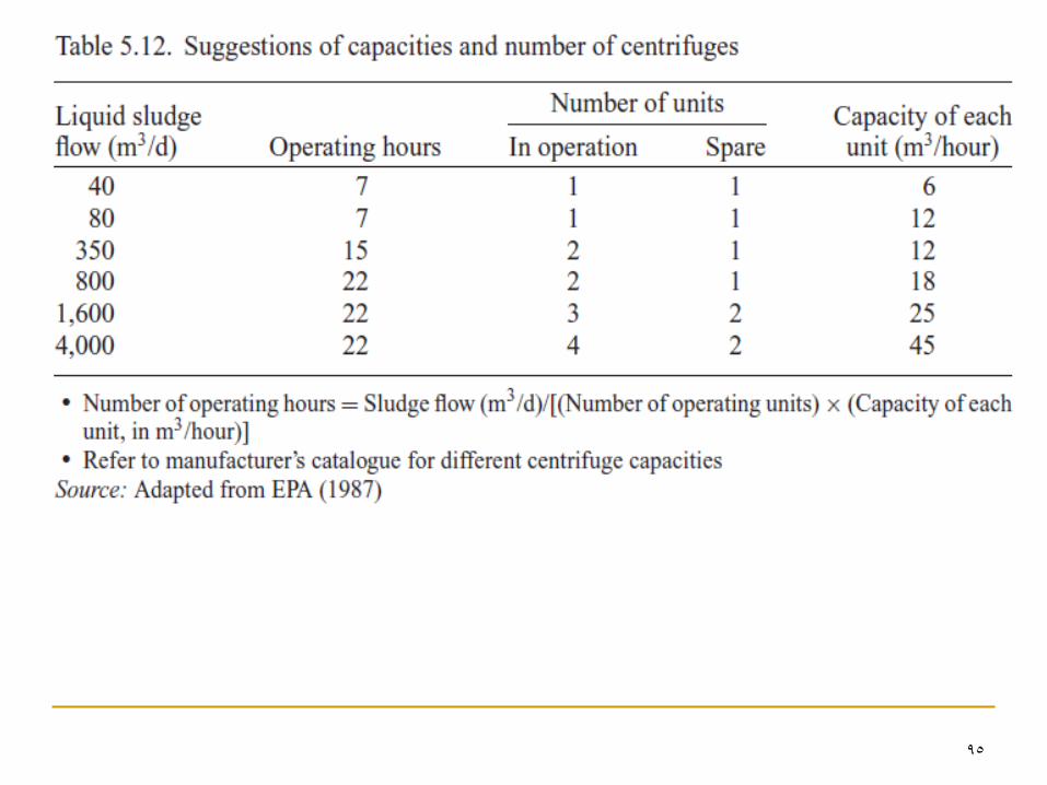
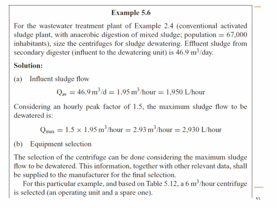
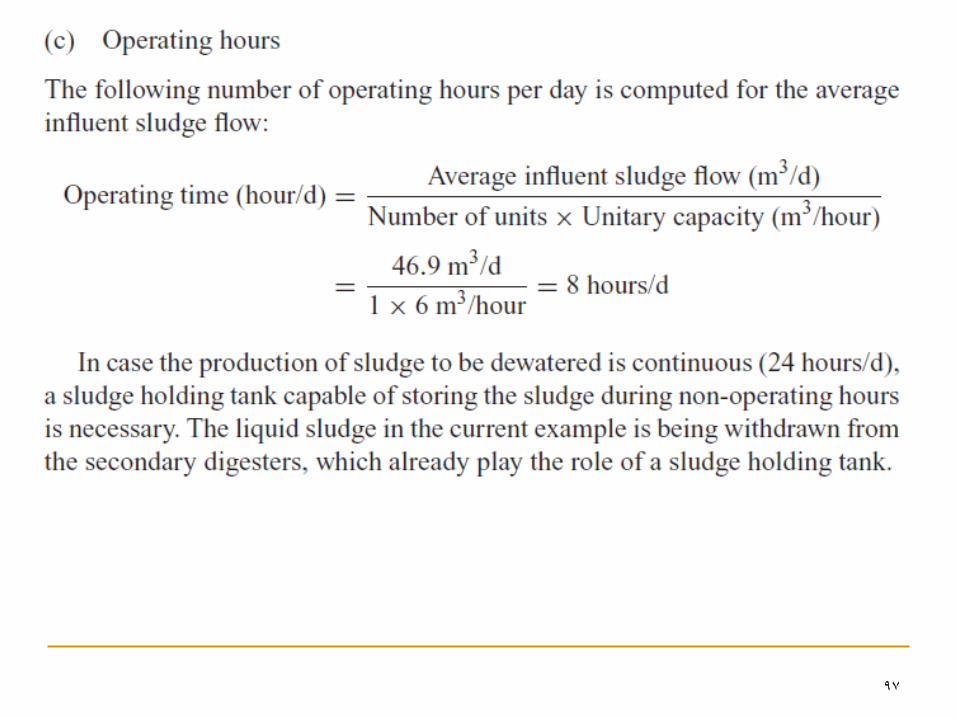
Design
The sizing of a centrifuge dewatering facility is based
upon manufacturer data on the equipment loading
capacity and the type of liquid sludge.
General guidelines to select the number of operating
and spare units are presented in Table 5.12.
95
96
97
98
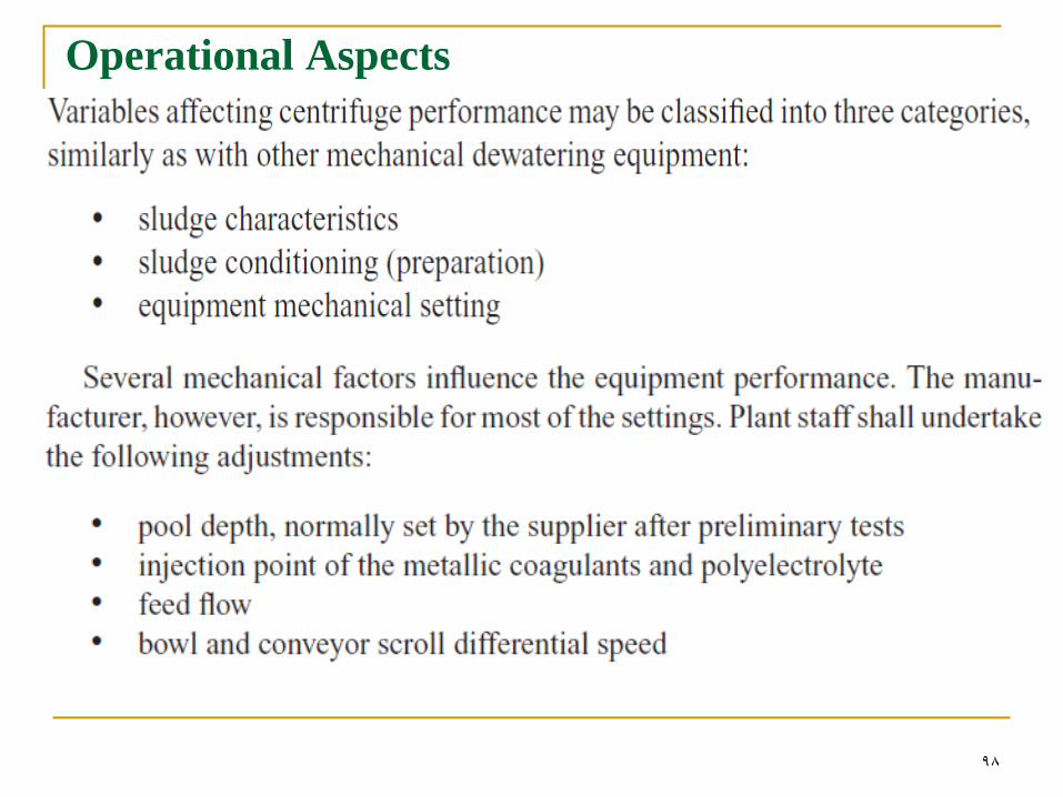
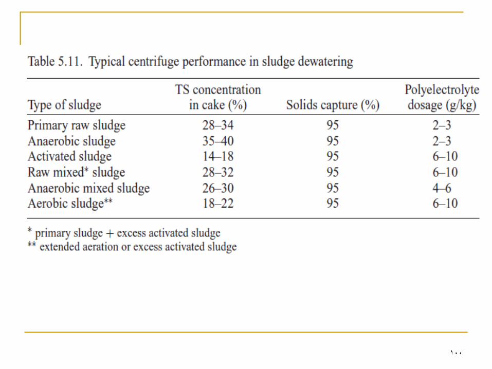
Operational Aspects
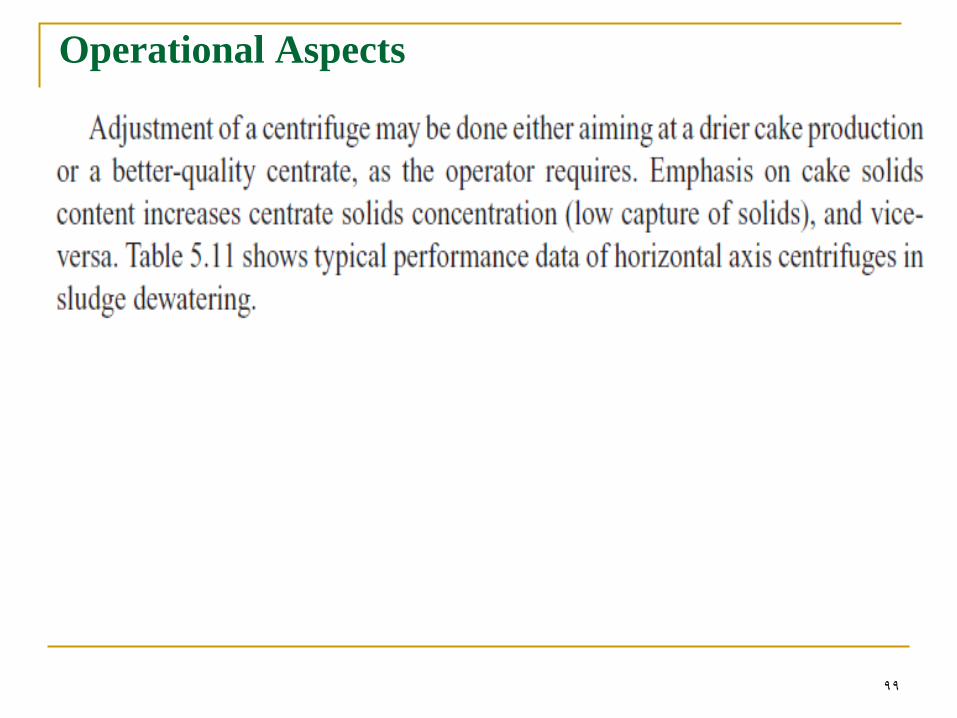
99
Operational Aspects
100
101
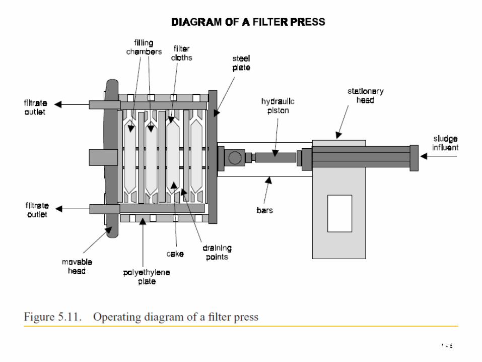
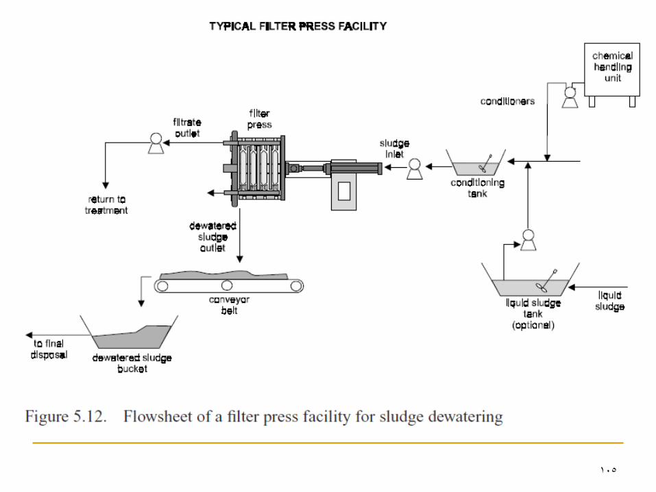
Filter Presses

102
103
104
105
106
107
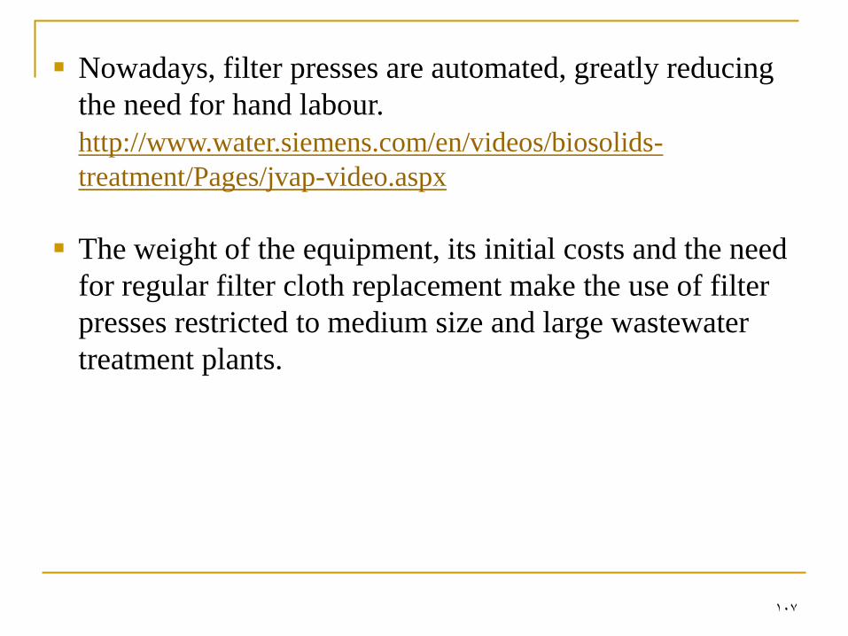
Nowadays, filter presses are automated, greatly reducing
the need for hand labour.
http://www.water.siemens.com/en/videos/biosolids-
treatment/Pages/jvap-video.aspx
The weight of the equipment, its initial costs and the need
for regular filter cloth replacement make the use of filter
presses restricted to medium size and large wastewater
treatment plants.
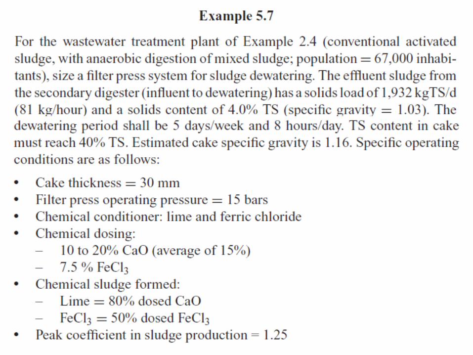
108
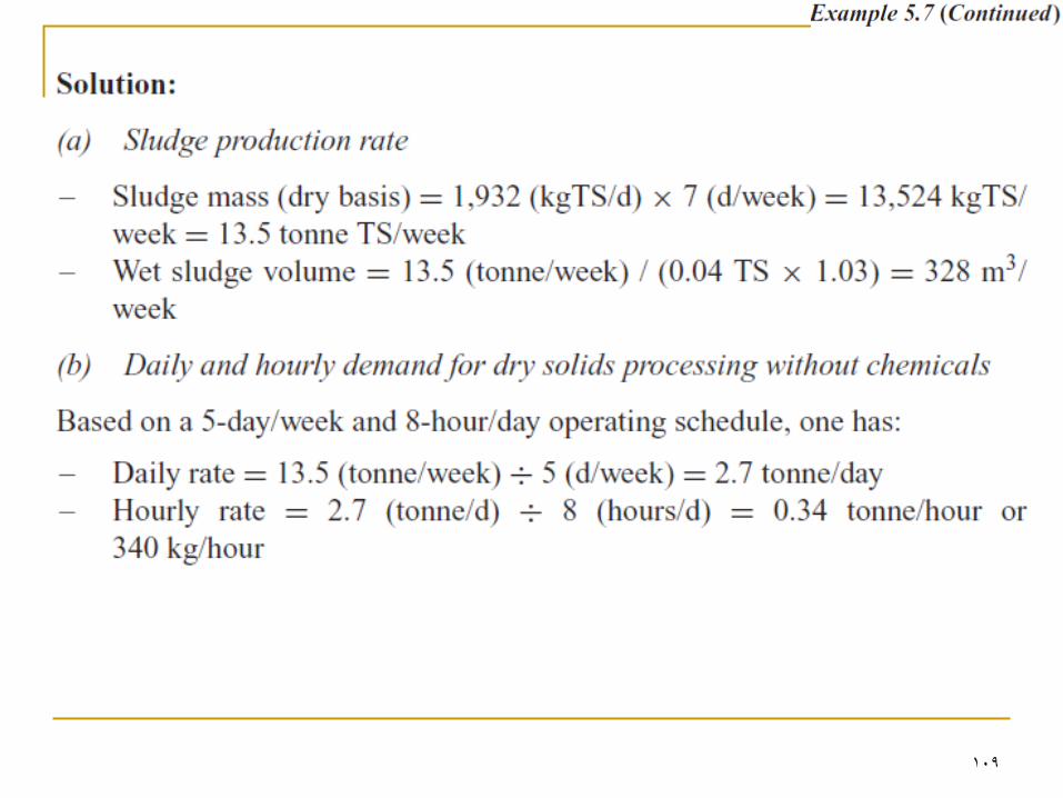
109
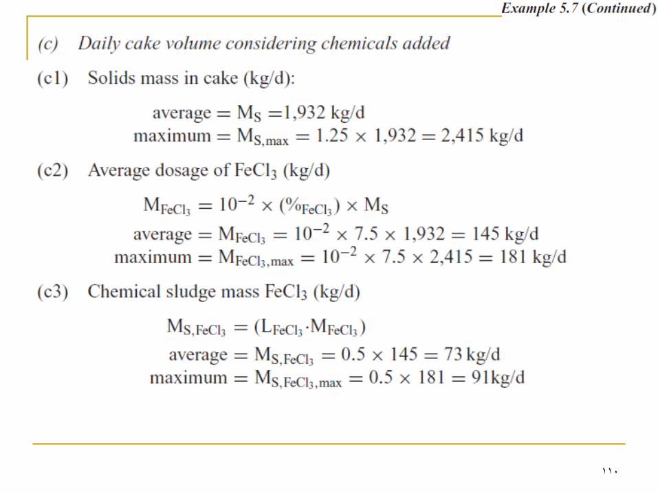
110
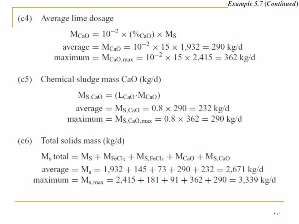
111

112
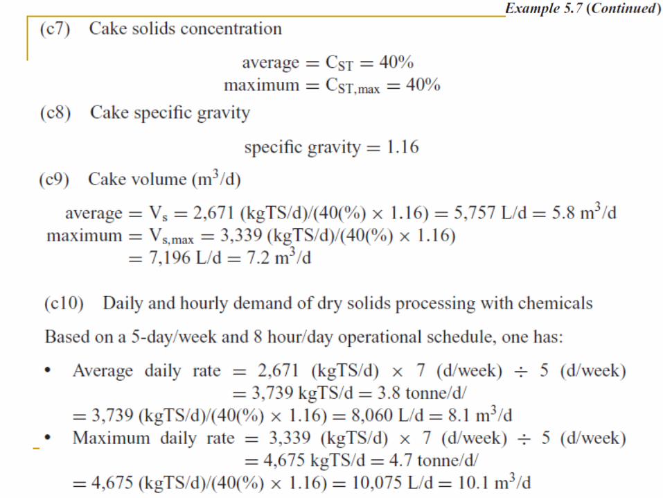
113
114
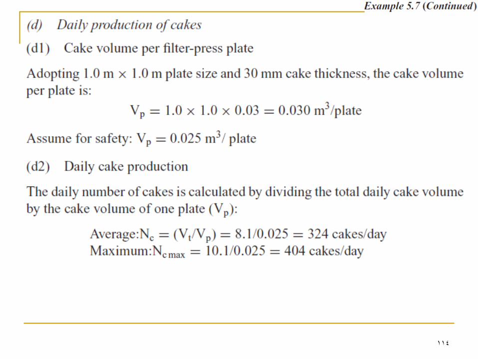
115
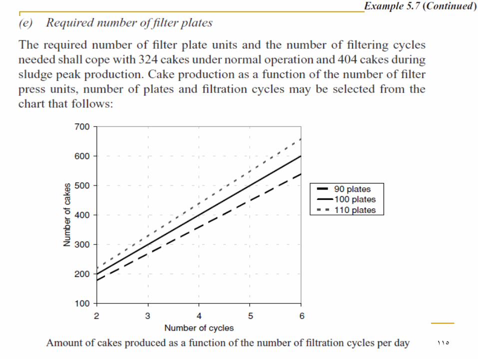
116
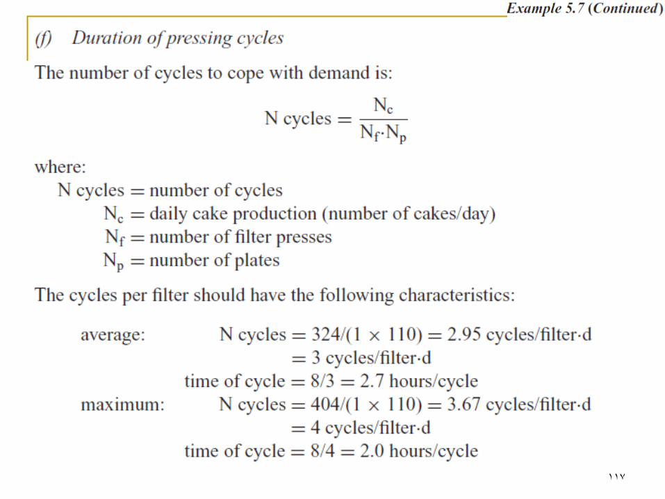
117
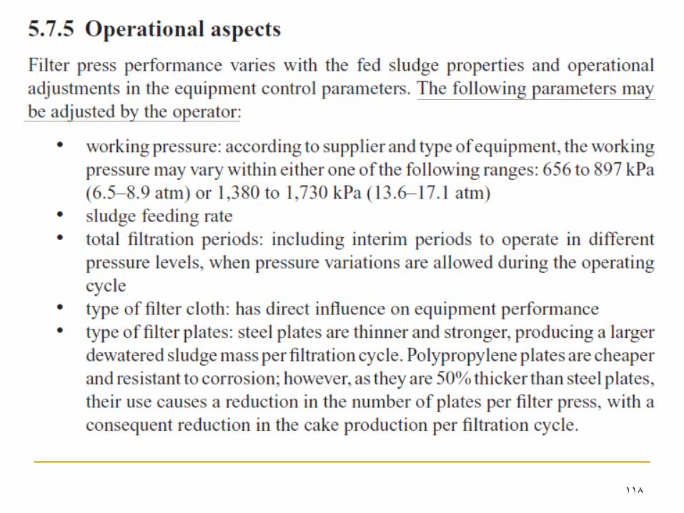
118
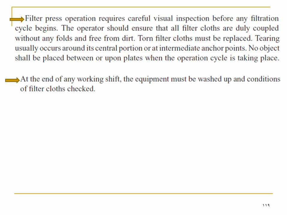
119
120
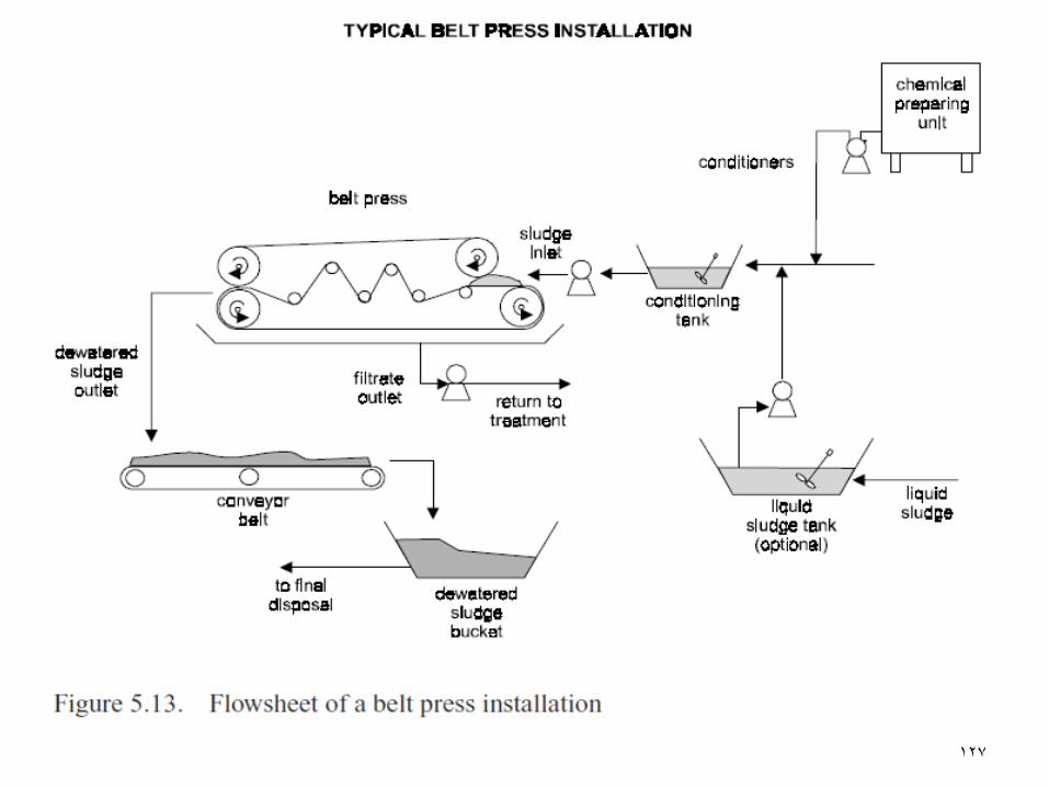
Belt Presses Also named: Belt-filter presses
Belt-filter presses are continuous-feed dewatering
devices that use the principles of chemical
conditioning, gravity drainage, mechanically applied
pressure to dewater sludge.
The belt press was introduced in the US in the early
1970s and has become one of the predominant sludge
dewatering devices.
Recent developments in centrifuges triggered intense
competition among suppliers of both types. Centrifuges are being favoured (despite the higher cost of
centrifuges)
121
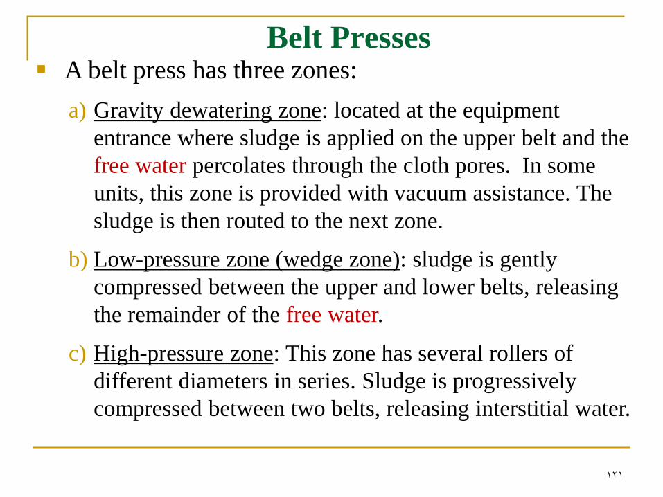
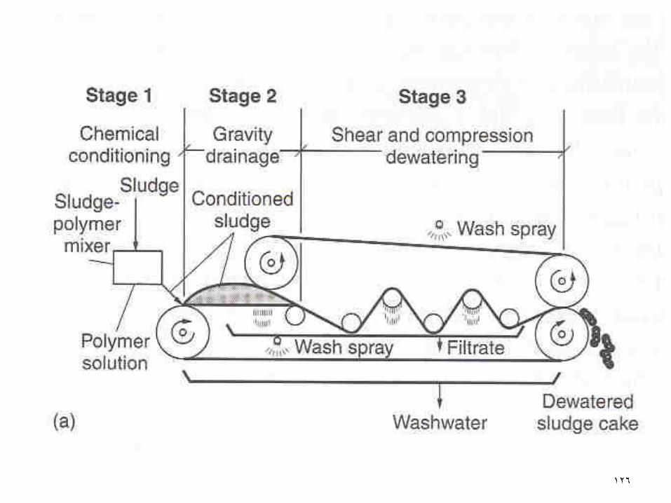
Belt Presses A belt press has three zones:
a) Gravity dewatering zone: located at the equipment
entrance where sludge is applied on the upper belt and the
free water percolates through the cloth pores. In some
units, this zone is provided with vacuum assistance. The
sludge is then routed to the next zone.
b) Low-pressure zone (wedge zone): sludge is gently
compressed between the upper and lower belts, releasing
the remainder of the free water.
c) High-pressure zone: This zone has several rollers of
different diameters in series. Sludge is progressively
compressed between two belts, releasing interstitial water.
122
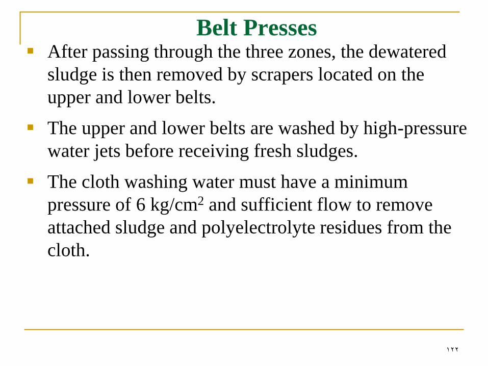
Belt Presses After passing through the three zones, the dewatered
sludge is then removed by scrapers located on the
upper and lower belts.
The upper and lower belts are washed by high-pressure
water jets before receiving fresh sludges.
The cloth washing water must have a minimum
pressure of 6 kg/cm2 and sufficient flow to remove
attached sludge and polyelectrolyte residues from the
cloth.
123
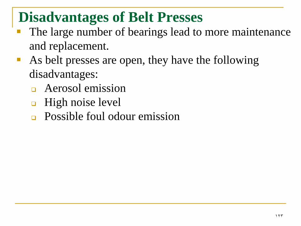
Disadvantages of Belt Presses The large number of bearings lead to more maintenance
and replacement.
As belt presses are open, they have the following
disadvantages:
Aerosol emission
High noise level
Possible foul odour emission
124
Advantages of Belt Presses
Low initial costs
Reduced electric power consumption
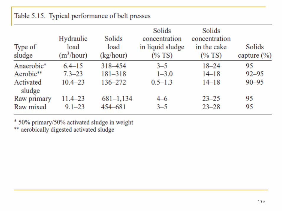
125
126
127
128
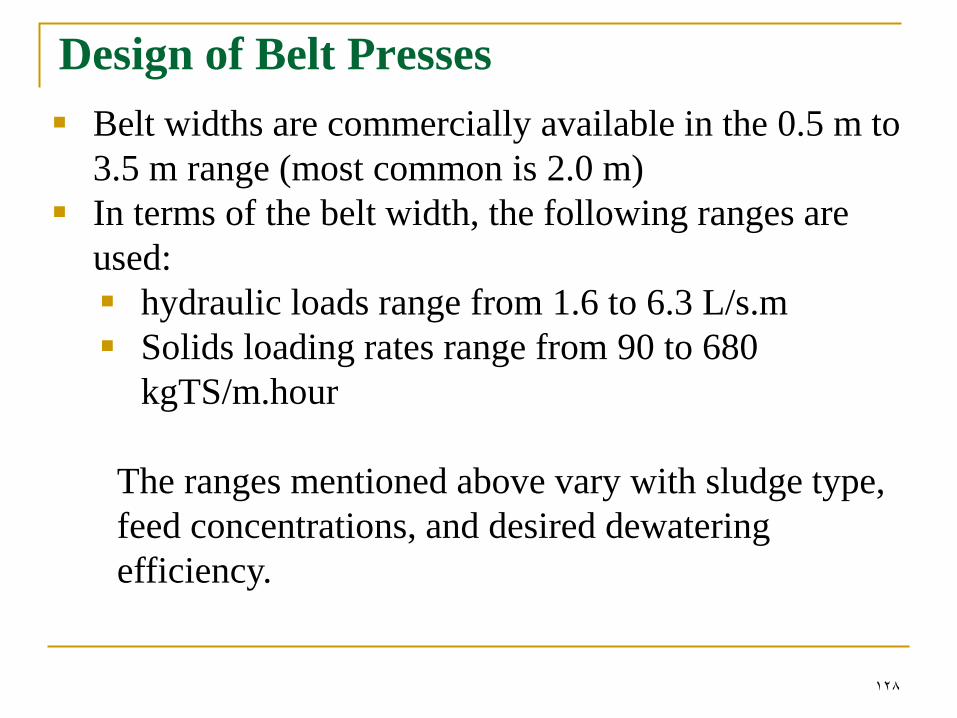
Design of Belt Presses
Belt widths are commercially available in the 0.5 m to
3.5 m range (most common is 2.0 m)
In terms of the belt width, the following ranges are
used:
hydraulic loads range from 1.6 to 6.3 L/s.m
Solids loading rates range from 90 to 680
kgTS/m.hour
The ranges mentioned above vary with sludge type,
feed concentrations, and desired dewatering
efficiency.

129
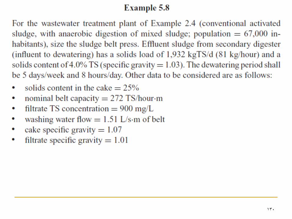
130
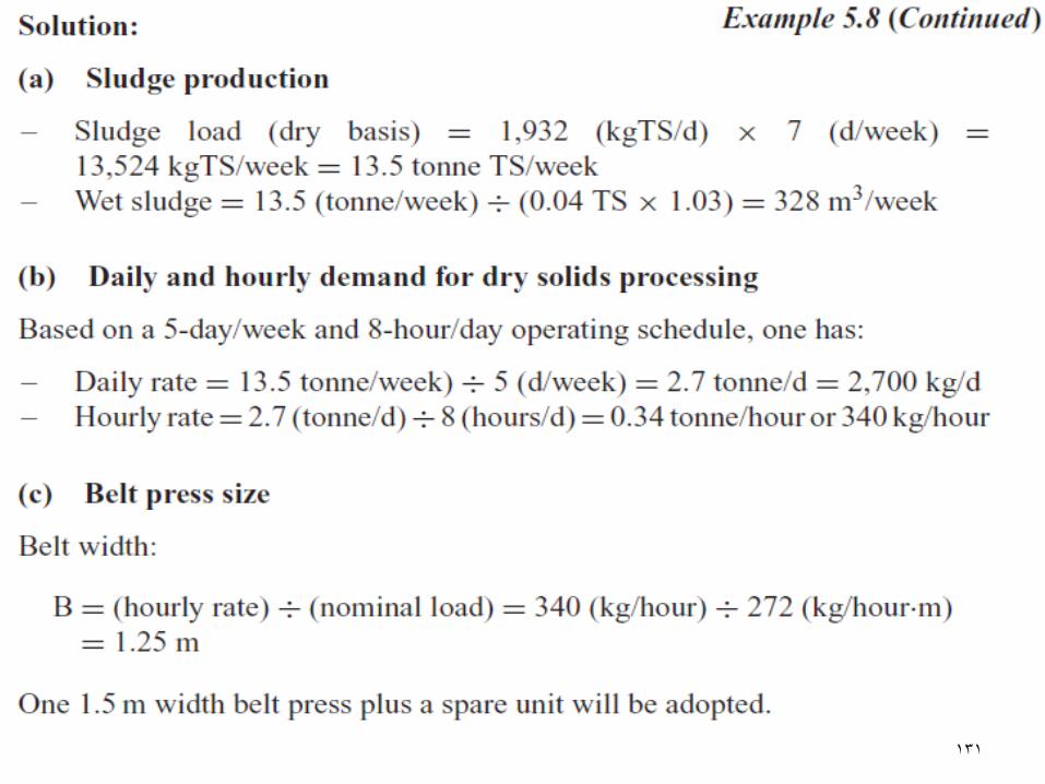
131
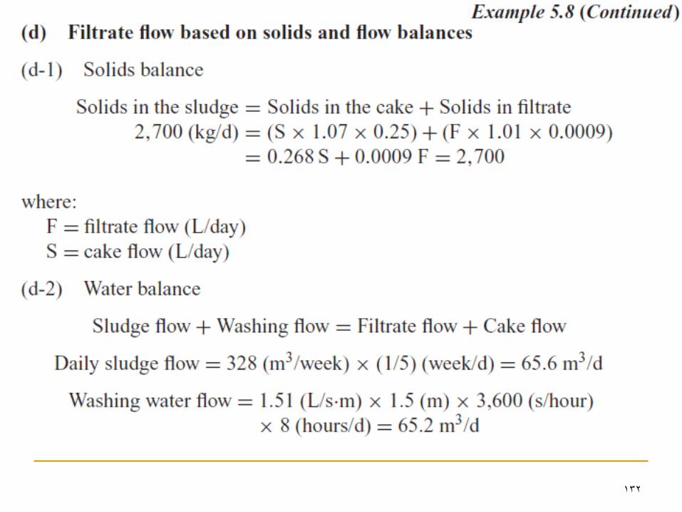
132
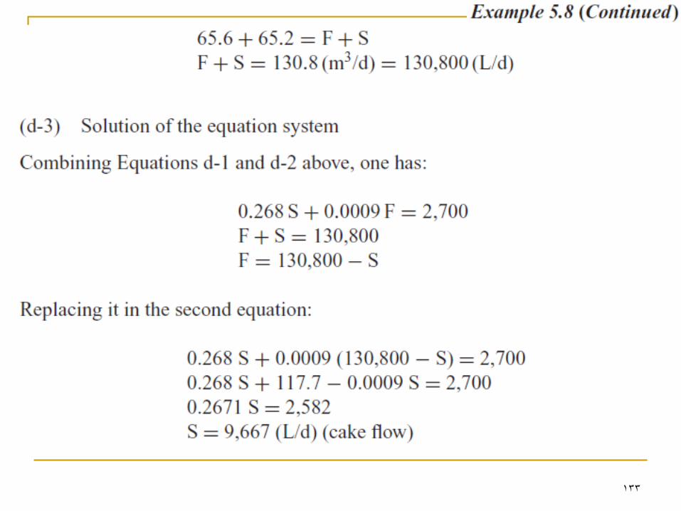
133
134