Embed Size (px)
Citation preview

Sta
mp
a:
Gra
fich
e Z
op
pe
lli 1
85
3 s
rl -
Do
sso
n-T
VC
od
. A
33
911
0 -
09
/04
Fracarro Radioindustrie S.p.A.Via Cazzaro n. 331033 Castelfranco V. (TV)ItaliaTel. +39 0423 7361Fax +39 0423 [email protected]
Fracarro France S.A.S.14 bis rue du Ratrait92158 Suresnes CedexFranceTel. +33 1 47283419Fax +33 1 47283421
Fracarro IbericaC/Ciudad de Elda, 4Poligono Ind. Fte. Del Jarro46988 ValenciaEspañaTel. +34/961340104-920Fax +34/961340691
Fracarro UK LtdIbex House, Keller CloseKiln Farm, Milton Keynes.MK11 3LLUKTel. +44(0)1908 571571Fax +44(0)1908 571570
Fracarro PortugalFracarro Tecnologia eAntenas de Televisao LdaQuinta da Fonte,Edifício D. Pedro IPaço d'ArcosPortugalTel. +351 21 000 16 35Fax +351 21 000 20 87
147
Catalogue of products for distributionof audio, video and data signal
SMATV Catalogue2005
SM
ATV
Cata
logue
147
Cop Fracarro 147 ok 23-09-2004 16:52 Pagina 1

3
page5
Antennas
page31Masthead products
page41TV and SAT headends
page65Multiswitches
page75
Fibre optic distribution Line amplifiers
page87MATV/SMATV distribution products
page111Fracarro customer service
Index
003_040 atennas e mastheads 23-09-2004 16:53 Pagina 3

ISO9001 certification
Conformity declaration
FRACARRO RADIOINDUSTRIE S.p.A.Via Cazzaro, 331033 Castelfranco Veneto (TV)
declares, under its sole responsibility, that the products listed in this catalogue, with theexception of those which do not fall within the field of application of the Legislative Decreen. 615 dated November 12, 1996 and Law no. 791 dated October 18, 1977 andmodification with Legislative Decree no. 626 dated November 25, 1996 (according toItalian law) are conform to the following regulations:
CEI EN 50083-2CEI EN 61000-3-2CEI EN 61000-3-3CEI EN 60065
and thus meet all the fundamental requirements of EEC Directives 89/336/CEE and73/23/CEE.
Our main goal has always been toachieve the highest quality andperformance on the products andservices we supply. FracarroRadioindustrie S.p.A. has beensuccessful in achieving this with the
Fracarro Quality System being officiallyrecognized on an international level withISO9001 certification.This certification confirms our productsare highly reliable, that we have amodern, efficient and professional salesorganization.
003_040 atennas e mastheads 23-09-2004 16:53 Pagina 4

Antennas
VHF AerialsBand I aerialsBand III aerialsBLV aerials
UHF AerialsYagi UHF channel grouped aerialsYagi UHF aerialsYagi pre-assembled UHF aerialsCAI benchmarkingBLU series aerialsDELTA series aerialsLAMBDA series aerials
Log - Periodic aerials
UHF panel aerials
Mechanical accessoriesAntennas accessoriesMasts
Indoor antennas
Parabolic dishesSat dishes - Penta seriesOffset Sat dishesKit systemLNB
Signal level meters
Page 67-8
9
1011121314
15-1617
18
19
20-2122
23
24-2526-27
2829
30
Since 1933 Fracarro has produced antennas for signal reception.Recently, in the UK, some of the antennas have obtained theCAI benchmark.For the reception of satellite signals Fracarro has developed itsown range of dishes “PENTA”: various sizes, particular shapeand with a high quality performance
003_040 atennas e mastheads 23-09-2004 16:53 Pagina 5

VHF aerialsBand I
Elem. No. BandwidthMHz
from to
Channels
Ital. Eur.
Gain
dB
Front-to-backratio> dB
Packaging
pcs kg.
Wind load at120km/h
Kg.
Dimensionboom elem.
cm. cm.
Item code
2A2B3A3B3C4B
2 52,5-59,5 A – 3,5 12 78,8 292 4,7 15 21,62 61-68 B E4 3,5 12 69 252 4,0 15 19,43 52,5-59,5 A – 5 16 127 294 16,6 15 25,13 61-68 B E4 5 16 105 252 5,8 15 23,93 81-88 C – 5 16 85,4 200 4,4 15 19,64 61-68 B E4 6,5 18 226 260 7,4 15 29,4
BANDS 1 SINGLE CHANNEL AERIALSMaximum mast diameter: ∅ 60mm. For larger mast sizes, vertical and tilt positioning, see page 20.Suitable for horizontal or vertical polarization. V.S.W.R. < 1,5.
6
2 elements 4 elements
“FM & DAB” RADIO OMNIDIRECTIONAL AERIALImpedence 75Ohms, F connector, V.S.W.R. < 1,5. Maximum mast diameter: ∅ 60mm.
Band BandwidthMHz
from to
Gain
dB
Packaging
pcs kg.
Wind load at120km/h
Kg.
32,187,5-108
Channels
Ital. Eur.
FM FMFM 10 10,7ANT1200A
—7,1216-240 — —— 5 —DAB
Band BandwidthMHz
from to
Gain
dB
Packaging
pcs kg.
Wind load at120km/h
Kg.
2,83,587,5-108
Channels
Ital. Eur.
FM FMFM 15 15,12FM
ANT1200 ADAB 2FM
VHF aerialsFM & DAB aerials
“FM” RADIO AERIALYAGI TYPE - Impendence 75Ohms, V.S.W.R. ≤ 1,5. Maximum mast diameter: ∅ 60mm.
new
new
N
N
003_040 atennas e mastheads 23-09-2004 16:53 Pagina 6

6 elements4 elements
Elem. No. Bandwidth
MHzfrom to
Channels
Ital. Eur.
Gain
dB
Front-to-backratio
> dB
Packaging
pcs kg.
Wind load at120km/h
Kg.
Dimension
boom elem.cm. cm.
Item code
4D_F4E_F4F_F4G_F4H_F6D_F6E_F6F_F6G_F6H_F6H1_F6E12_F
4 174-181 D E5 6,5 18 116 87 2,2 20 16,04 182,5-189,5 E – 6,5 18 111 84 2,1 20 15,04 191-198 F – 6,5 18 106 80 2,0 20 14,94 200-207 G – 6,5 18 102 76 1,9 20 14,54 209-216 H E10 6,5 18 97 73 1,8 20 13,96 174-181 D E5 9 25 210 88 3,5 10 22,76 182,5-189,5 E – 9 25 201 82 3,3 10 22,36 191-198 F – 9 25 192 82 3,2 10 21,56 200-207 G – 9 25 184 75 3,1 10 20,86 209-216 H E10 9 25 177 73 3,0 10 20,06 216-223 H1 E11 9 25 171 72 2,9 10 19,56 223-230 H2 E12 9 25 166 67 2,8 10 19,1
BAND 3 SINGLE CHANNEL AERIALSMaximum mast diameter: ∅ 60mm. For vertical and tilt positioning see page 20. V.S.W.R. < 1,3.
VHF BAND 3 WIDEBAND AERIALSMaximum mast diameter: ∅ 60mm. For vertical and tilt positioning, see page 20. These antennas are suitable for areas whereseveral band 3 TV channels may be received (ch. E5÷E12).
Elem. No.
Band Bandwidth
MHzfrom to
Channels
Ital. Eur.
Gain
dB
Front-to-backratio
> dB
Packaging
pcs kg.
Wind load at120km/h
Kg.
Dimension
boom elem.cm. cm.
Item code
4E512_F6E512_F
4 3 174-230 E5÷E12 4÷5 14 108 83 2,0 20 14,46 3 174-230 E5÷E12 5÷7 17 181 82 3,0 20 20,0
7
VHF aerialsBand III
003_040 atennas e mastheads 23-09-2004 16:53 Pagina 7

VHF AERIALS BAND IIIWith “F” connectorsImpendance 75Ohms.Polarisation H or V.Maximum mast diameter: ∅ 60mm.
Numberof
elements
Channels Frequencies
MHz
GainTyp.
dB
Front/backratio
> dB
V.S.W.R.
dB
Weight
kg.
DimensionsL x l x h
mm
Wind loadat 120km/h
kg.
VHF BAND III 1/2 BAND
VHF BAND III WIDEBAND
ANT3030507
ANT3030810
ANT3070507
ANT3070810
ANT3060510
ANT3100510
3 L5 - L7 174-202 6 >12 <1,5 3,3 760x880x75 0,8
3 L8 - L10 202-223 6 >14 <1,5 2,7 750x630x75 0,8
7 L5 - L7 174-202 10 >12 <1,5 6,9 1560x850x75 1,3
7 L8 - L10 202-223 11 >13 <1,5 6,5 1560x750x75 1,3
6 L5 - L10 174-223 8 >10 <1,5 5,6 1190x860x75 1,2
10 L5 - L10 174-223 9 >10 <1,5 9,7 2370x860x75 1,7
Item code
Single pack Multiple pack Volume Weight
pcs Dimension Lxlxh (mm) dm3 kg
ANT3030507
ANT3030810
ANT3070507
ANT3070810
ANT3060510
ANT3100510
plastic bag 10 800x310x230 57 9
plastic bag 10 800x310x231 57 9
plastic bag 10 800x310x232 57 14
plastic bag 10 800x310x233 57 14
plastic bag 10 800x310x234 57 13
plastic bag 10 1180x300x270 96 18
PACKAGING
ANT3030.. ANT3070.. ANT3100510
VHF aerialsBand III
8
new new new
N
N
N
N
N
N
003_040 atennas e mastheads 23-09-2004 16:53 Pagina 8

9
Elem. No. Band Bandwidth
MHzfrom to
Channels
Ital. Eur.
Gain
dB
Front-to-backratio
> dB
Packaging
pcs kg.
Wind load at120km/h
Kg.
Dimensions
boom elem.cm. cm.
BAND 3 - WIDEBANDMast bracket: max. diameter 60mm. For larger mast sizes, vertical and tilt positioning, see page 20. Suitable for horizontal orvertical polarization. From an aesthetic point of view these models complement the Fracarro BLU series antennas for highendinstallations. Some of the technical and aesthetic innovations used in these antennas are protected patent.
CHARACTERISTICS:
High gain, and optimised impedance match. Excellent directivity. Superior electrical and mechanical qualities due toMagnesium/Aluminium alloy construction. Weatherproof terminal box with screw on cover. Partially pre-assembled for aneasier installation.V.S.W.R. < 1,4.
With “F” connectorBLV4FBLV6F
4 3 174-230 E5÷E12 6,5÷8 14 70 78 3,0 10 1,236 3 174-230 E5÷E12 7,5÷11 17 155 78 4,5 3 2,00
BLV6FBLV4F
Item code
VHF aerialsBLV aerials
003_040 atennas e mastheads 23-09-2004 16:53 Pagina 9
10
UHF CHANNEL GROUPED AERIALSMaximum mast diameter: ∅ 62mm.Bandwidth: from 3 up to 8 adjacent channels. Suitable for mounting with horizontal or vertical polarization.For larger sizes, vertical and tilt positioning see page 20. V.S.W.R. < 1,4.
10 SPEC. 860÷960 — 7 ÷9,5 20 94 16 1,0 20 10,0
10 4 470÷494 21-23 11 24 128 36 2,8 20 14,4
10 4 494÷518 24-26 11 24 123 34 2,7 20 13,8
10 4 518÷550 27-30 11 24 116 32 2,6 20 13,5
10 4 550÷582 31-34 11 24 111 30 2,5 20 13,2
10 5 582÷622 35-39 11 24 108 28 2,4 20 12,7
10 5 622÷678 40-46 11 24 110 25 2,4 20 12,5
10 5 678÷734 47-53 11 24 96 24 2,3 20 12,0
10 5 734÷798 54-61 11 24 100 22 2,3 20 12,0
10 5 798÷862 62-69 11 24 94 20 2,2 20 11,7
20 4 550÷582 31-34 14 26 249 36 4,4 20 19,2
20 5 622÷678 40-46 14 26 209 25 3,9 20 17,2
10/860960
10ALFA/R
10BETA/R
10GAMMA/R
10DELTA/R
10/3539R
10/4046R
10/4753R
10/5461R
10/6269R
20DELTA
20/4046
CA1
NARROW BAND ANTENNAS
0,8 20 5,9
AUXILIARY BOOMfor 20-element UHF antennas.
CA1 auxiliary boom increases to the mechanical strength of the 20 element antennas. The CA1 is recommended for usewith the band 4 narrow band models when used in high wind locations, and is optional for the physically smaller band 5,20 elements antenna models.
Elem. No. Band Bandwidth
MHzfrom to
Channels
Ital. Eur.
Gain
dB
Front-to-backratio> dB
Packaging
pcs kg.
Wind load at120km/h
Kg.
Dimensions
boom elem.cm. cm.
Item code
10/../R10/860960
20/.. Auxiliary boom CA1
UHF aerialsYagi UHF channel grouped aerials
003_040 atennas e mastheads 23-09-2004 16:53 Pagina 10

YAGI UHF with 4 ELEMENT REFLECTORMaximum mast diameter: ∅ 42mm.For larger sizes, vertical and tilt positioning see page 20. Suitable for mounting with horizontal or vertical polarization.
Elem. No. Band BandwidthMHz
from to
Channels
Ital. Eur.
Gain
dB
Front-to-back ratio
> dB
V.S.W.R.
<
Packaging
pcs kg.
Wind load at120km/h
Kg.
Dimensionsboom elem.
cm. cm.
Item code
10BL410BL510BL4520BL420BL520BL45
10 4 470-606 E21-37 8÷11 21 1,3 135 36 2,8 20 14,310 5 606-862 E38-69 8÷11 20 1,4 103 28 2,3 20 11,910 UHF 470-862 E21-69 6,5÷9,5 20 1,4 94 36 2,3 20 12,120 4 470-606 E21-37 10÷13 23 1,4 232 37 4,2 20 19,020 5 606-862 E38-69 10÷13 22 1,6 208 26 3,8 20 17,020 UHF 470-862 E21-69 6,5÷11 22 1,5 187 39 3,6 20 16,9
10BL.. 20BL..
10RD45F 20RD..
YAGI UHF - with GRID REFLECTORMaximum mast diameter: ∅ 42mm.For larger sizes, vertical and tilt positioning see page 20. Suitable for mounting with horizontal or vertical polarization.
Elem. No. Band BandwidthMHz
from to
Channels
Ital. Eur.
Gain
dB
Front-to-back ratio
> dB
V.S.W.R.
<
Packaging
pcs kg.
Wind load at120km/h
Kg.
Dimensionsboom reflector
cm. cm.
20RD420RD520RD45
10RD4F10RD5F10RD45F
20 4 470÷606 E21-37 10÷13 25 1,3 235 36 5,1 20 26,520 5 606÷862 E38-69 11÷14 26 1,6 210 36 4,5 20 24,620 UHF 470÷862 E21-69 7÷12 25 1,4 193 36 4,3 20 24,0
10 4 470÷606 E21-37 9÷11 23 1,3 137 36 2,9 20 18,310 5 606÷862 E38-69 9÷11 23 1,4 103 36 2,5 20 16,110 UHF 470÷862 E21-69 7÷10 23 1,4 99 36 2,5 20 16,0
20RD4F20RD5F20RD45F
20 4 470÷606 E21-37 10÷13 25 1,3 235 36 5,1 20 26,520 5 606÷862 E38-69 11÷14 26 1,6 210 36 4,5 20 24,620 UHF 470÷862 E21-69 7÷12 25 1,4 193 36 4,3 20 24,0
With “F” connector
11
UHF aerialsYagi UHF
003_040 atennas e mastheads 23-09-2004 16:53 Pagina 11

12
YAGI UHF - PRE-ASSEMBLED with 4 element REFLECTORImpendance 75Ohms.Fixing clamp: Maximum mast diameter 55mm; polarisation H or V; on site adjustment.
Numberof
elements
Channels Frequencies
MHz
Gainmin. max
dB
Front / backratio
> dB
Weight
kg.
DimensionsL x l x h
cm
Wind load at120km/h
dm2
ANT4113812
ANT4116912
ANT4223812
ANT4226912
11 21-38 470-614 8-12 >18 7 78x33x30 0,75
11 39-69 614-862 8-12 >18 7 68,5x30x25 0,73
22 21-38 470-614 12-17 >18 10 219x33x33 1,4
22 39-69 614-862 10-17 >18 10 190x33x25 1,3
Item code
Unit L x l x hcm.
Volumedm3
Weightkg
Antennasystem
L x l x hcm.
Volumedm3
Weightkg
ANT4113812ANT4116912ANT4223812ANT4226912ANT4100012ANT4220012
in bag 81x24x5 9,72 1,02 10 81x24x50 98 11,4in bag 69x24x5 8,3 1,05 10 73x27x59 116 11,0
in cardboard 134x25x6 20,1 1,91 10 138x28x67 259 19,6in cardboard 117x21x6 14,5 1,73 10 120x24x67 193 17,8
in a bag 105x32x10 16,8 1,1 10 120x34x26 80 11,6in a bag 135x32x15 38,88 1,7 10 120x33x40 1501 17,6
PACKAGING
YAGI UHF - PRE-ASSEMBLED with grid REFLECTORConsists of yagi symmetrical half wave.Impendance 75Ohms.Fixing clamp: Maximum mast diameter 55mm; polarisation H or V; on site adjustment.
Channels Frequencies
MHz
Gainmin. max
dB
Acceptanceangle
(°)
Front / backratio
> dB
Weight
kg.
DimensionsL x l x h
cm
Wind load at120km/h
dm2
ANT4100012ANT4220012
10 21-69 470-862 7-13 70-34 >20 9 93x41x38 0,822 21-69 470-862 9-16 44-22 >20 13 200x41x38 1,4
Numberof
elements
ANT4116912 ANT4220012
UHF aerialsYagi UHF pre-assembled
003_040 atennas e mastheads 23-09-2004 16:53 Pagina 12

Aerial Benchmark
As for the reception of Digital Terrestrial Television (DTT) signals in the UK, the receivingaerials are required to be designed and manufactured to a minimum industry standard.It is believed that due to the high level of analogue signals in comparison to the lower digitalsignals, the correct aerial has not always been fitted. This has been mainly prevalent in fringereception areas where DTT reception issues have invariably been improved with theinstallation of a correct aerial. The Confederation of Aerial Industries and the Digital Television Group have thereforedecided that an approval process is required to ensure that aerials conform to a minimumstandard. The benchmark specification is used to determine the characteristics of an aerialrequired to obtain stable DTT reception. It does not alter the basic requirements of aerialdesign but highlights important parameters so that satisfactory DTT reception may beachieved. Aerials that have been approved will display a "mark", confirming that the required standardhas been reached.Although this benchmark is not a legal requirement, experience in the industry has indicatedthat it will be to the industry's advantage to supply equipment to this recommendation. The standards BS 5640: 1,11 1978 and ITU-R. BT. 419-3 have been used as a guide in settingthe specification. The benchmark is to set the minimum performance required for various standards of aerial.It does not cover ease of assembly, durability and installation. The Confederation of AerialIndustries issued a Code of Practice for the installation of television aerials which isrecommended to be followed.
BLU420F Blu Series 42 elements UHF Antenna
(page 14) Certification Number: CAI/AB 012
BLU220F PLUS Blu Series 22 elements UHF Antenna
(page 14) Certification Number: CAI/AB 017
DELTA500 Delta Series 5 elements UHF Antenna
(page 16) Certification Number: CAI/AB 018
DELTA800 Blu Series 8 elements UHF Antenna
(page 16) Certification Number: CAI/AB 012
LP45N Log periodic UHF Antenna
(page 18) Certification Number: CAI/AB 016
13
AERIALS
CAI benchmarking
003_040 atennas e mastheads 23-09-2004 16:53 Pagina 13

14
UHF aerialsBLU series
BLU420F
Elem. No. Band Bandwidth
MHzfrom to
Channels
Ital. Eur.
Gain
dB
Front-to-backratio> dB
Packaging
pcs kg.
Wind load at120km/h
Kg.
Dimensions
boom elem.cm. cm.
Item code
BLU SERIES: UHF AERIALS Maximum mast diameter: ∅ 60mm.Pre-installed antennas with high performances and designed for the following:- High gain- Good directivity (with particular attention to the level of side LOBE and to the F/B ratio)- Good V.S.W.R. This characteristic eliminates double images on the TV set by reducing the reflected signals on the cable.
The 90 element antenna is suitable mainly in areas where:1) the signal is very weak where gain and bandwidth are critical.2) rejection of unwanted signal is optimised by a narrow beamwidth and larger reflectors on the BLU920F.
42 and 22 element antennas should be used where protection from side or rear unwanted signals is required. Side lobe compression and high front-to-back ratio makes the difference from other UHF broad band antennas. Suitable for vertical or horizontal mounting. With “F” connector. V.S.W.R. < 1,5dB.
BLU220F
BLU224F
BLU225F
BLU420F (*standard2)
BLU424F
BLU425F
BLU920F
22 UHF 470÷862 E21÷69 9÷12 25 84 50 5,5 10 14,8
22 4 470÷606 E21÷37 10÷11 25 92 50 5,5 10 17,2
22 5 606÷900 E38÷69 11÷14 25 84 50 5,5 10 14,5
42 UHF 470÷862 E21÷69 10÷14 26 119 50 7,0 10 20,8
42 4 470÷606 E21÷37 11÷12 26 122 50 7,0 10 20,8
42 5 606÷900 E38÷69 13÷15 26 119 50 7,0 10 20,8
90 UHF 470÷862 E21÷69 11÷18 27 242 50 12,0 3 9,5
BLU220PLUSAerial Benchmark Aerial Benchmark
With tube reflectorBLU220PLUS(*standard3) 22 UHF 470÷862 E21÷69 10÷12 25 84 50 7,5 8 12,16
* For more information see www.dtg.org.uk web site.
Standard 2 Standard 3
**
new new
N
N
003_040 atennas e mastheads 23-09-2004 16:53 Pagina 14

(1) Gain measured between channels 21 and 47
UHF aerialsDELTA series
15
ANT41600 ANT42200
DELTA series: UHF AERIALSCosists of whole symmetrical wave director, Impedence 75Ohms. F connectorFixing clamp: Maximum mast diameter 55mm; polarization H o V , on site adjustment
Channels Frequencies
MHz
Gainmin. max
dB
Front / backratio
> dB
Weight
kg.
DimensionsL x l x h
cm
Wind load at120km/h
dm2
ANT41538ANT41569ANT41600ANT42238ANT42200
21-39 470-622 10-14 22 15 160 x 50 x 60 1,3536-69 590-862 11-13 22 15 121 x 50 x 60 1,2521-69 470-462 11-15 25 15 163x 41 x 38 1,421-39 590-862 10-16 26 17,5 260 x 50 x 60 1,921-69 470-462 13-17 27 17,5 200 x 41 x 38 1,85
Single pack Multiple pack
L x l x hcm.
Volumedm3 pcs L x l x h
cm.Volume
dm3
WeightKg
ANT41538ANT41569ANT41600ANT42238ANT42200
carton box 73x38x7,5 22,5 5 80x45x40 141 10carton box 73x38x7,5 22,5 5 80x45x40 141 10carton box 73x38x7,5 22,5 5 80x45x40 141 10carton box 92x38x7,5 27,6 5 95x45x40 171 12carton box 92x38x7,5 27,6 5 95x45x40 171 12
PACKAGING
Item code
003_040 atennas e mastheads 23-09-2004 16:53 Pagina 15
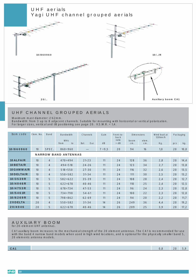
DELTA500 DELTA800
DELTA SERIES: UHF AERIALS Cosists of whole symmetrical wave director, Impedence 75Ohms. F connectorFixing clamp: Maximum mast diameter 60mm; polarization H o V , on site adjustment
UHF aerialsDELTA series
Channels Frequencies
MHz
Gainmin. max
dB
Front / backratio
> dB
DimensionsL x l x h
cm
Wind loadat 120Km/h
Kg
21-69 470-462 8-14 17 77x58x52 4,521-69 470-462 10-15 20 107,5x58x52 5,5
Single pack Multiple pack
pcs L x l x hcm
WeightKg
plastic bag 7 880x445x330 11plastic bag 6 880x440x325 10,2
PACKAGING
Item code
Aerial Benchmark Aerial Benchmark
Standard 3 Standard 2
**
* For more information see www.dtg.org.uk web site.
16
new new
NN
DELTA500 (*standard3)
DELTA800 (*standard2)
DELTA500DELTA800
003_040 atennas e mastheads 23-09-2004 16:53 Pagina 16

(1) Gain measured between channels 21 and 47
17
ANT 509 ... ANT 514
LAMBDA: UHF AERIALSConsists of whole wave directors, dihedral reflector, symmetric transformer, snap in to place dipoles.Impedance 75Ohms.Fixing clamp: Maximum mast diameter 55 mm; polarisation H or V; on site adjustment.
ChannelsNumber ofelements
Frequencies
MHz
Gainmin. max
dB
Front / backratio
> dB
Weight
kg
DimensionsL x l x h
cm
Wind load at120km/h
dm2
ANT5093802ANT5094702(1)
ANT5096902ANT5143802ANT5144702(1)
ANT5146902
9 21-38 470-614 13,5-16 >24 16 160x50x71 1,69 21-47 470-686 13-16 >24 165 153x50x71 1,99 21-69 470-862 12-16,5 >25 15 150x50x71 1,714 21-38 470-614 15,5-18 >24 19 238x50x71 1,814 21-47 470-686 14,5-18 >24 19 238x50x71 2,514 21-69 470-862 12-18 >24 17,5 150x50x71 2,2
Unit L x l x hcm.
Volumedm3
Weightkg
Quantityper pallet
ANT5093802ANT5094702ANT5143802ANT5144702ANT5096902ANT5946902
in cardboard 96x43x14 56 2,6 25in cardboard 96x43x14 56 2,5 25in cardboard 96x43x17 70 3,7 25in cardboard 96x43x17 70 3,5 25in cardboard 96x43x17 56 2,6 25in cardboard 96x43x17 70 3,7 25
PACKAGING
Item code
UHF aerialsLAMBDA series
003_040 atennas e mastheads 23-09-2004 16:53 Pagina 17

Band Bandwidth
MHzfrom to
Gain
dB
Front-to-backratio
> dB
V.S.W.R.
<
Packaging
pcs kg.
Wind load at120km/h
Kg.
Dimensions
boom elem.cm. cm.
Item code
LOG-PERIODIC AERIALSMaximum mast diameter: ∅ 60mm.For assembly in vertical or horizontal position without additional accessories.
Anodised aluminium
3+UHF
174÷230470÷900
9,09,0
2127
1,51,8 111 86 20 19,63,9LP345HV
3+UHF
174÷230470÷900
8,58,0
1826
1,81,9 72 86 20 16,32,7
UHF 470÷900 10,0 28 1,7 94 32 10 7,93,0
LP345MHV
LP45HV
5 606÷900 11,0 30 1,7 94 24 10 7,53,0LP5HV
UHF 470÷900 10 28 1,7 111 32 15 143LP45N (*standard4)
3+UHF
174÷230470÷900
9,09,5
2227 1,7 71 79 10 8,82,8LPV345HV
3+4
174÷230470÷606
79
1923 1,5 111 86 10 7,52,8LP34HV
18
LP45N
LPV..HV LP..HV
Log-Periodic aerials
Aerial Benchmark
Standard 4
*
* For more information see www.dtg.org.uk web site.
new
N
003_040 atennas e mastheads 23-09-2004 16:53 Pagina 18

UHF aerials PANELMaximum mast diameter: ∅ 60mm.Plastic covered steel reflector panel. Aluminium radiant elements for PU4-P54 and steel for PU4A. V.S.W.R. ≤ 2dB.
Band Bandwidth
MHzfrom a
Gain
dB
Front-to-backratio
> dB
Packaging
pcs kg.
Wind load at120km/h
Kg.
Dimensions
cm.
Item code
PU4A(1)
PU4(1)
P54(1)
5,04,03,2
182224
76,5 x 5038,5 x 7132 x 62
9÷129÷129÷12
470÷862470÷862570÷920
UHFUHF
5
10 14,115 15,615 14,3
Band Bandwidth
MHzfrom a
Gain
dB
Front-to-backratio
> dB
Packaging
pcs kg.
Wind load at120km/h
Kg.
Dimensions
cm.
PU8PU8V(2)
PU16
131326
202020
88,5 x 72156 x 40167 x 720
12÷1612÷1615÷20
470÷862470÷862470÷862
UHFUHFUHF
1 2,751 2,81 4,8
UHF MULTIPLE PANEL ANTENNASHigh gain and directivity particularly useful:1) with weak signals2) with signals from many different transmitters.Due to their high directivity, chosen signals are protected from unwanted signals.V.S.W.R. ≤ 2dB.
UHF panel aerials
PU4-P54PU4A
19
003_040 atennas e mastheads 23-09-2004 16:53 Pagina 19

PVZ-60 PVF-60 PG20
ANTENNA FITTINGSTreated galvanized steel. For masts ∅ 42mm max
Item code
For vertical polarization - Length 280mm - Packaging 40pcs
For vertical polarization of two coupled band 3 or 4 antennas. - Length 950mmPackaging 20pcs
For tilt adjustment of two coupled 11 element VHF band 3 antennas with horizontal polarization, or forcoupling one of them with a UHF antenna. - Length 1500mm. - Packaging 20pcs
For masts ∅ 60mm max
For zenithal orientation. - Packaging 25pcsFixed vertical polarization (only 10 elements UHF)
Fixed horizontal polarization. - Packaging 25pcs
For vertical polarization panel antennas. - Packaging 20pcs
PV10
PV20
PV5
PVZ-60
PVF-60
PVP
PG20
ELBOW SHAPED MAST FOR ROOF
Diameter 42x3mm - Length 2m - Tube grip: diameter 25÷45mm. Packaging 1pc
Antennas accessories
20
– standard n.r. = not recommended
ANTENNA FITTING APPLICATIONS - SPECIAL NON-STANDARD ACCESSORIES FOR DIFFERENT INSTALLATION requirements and mast diameters.
VHFb.1 e b.2
b.3
mast Ø max mm
20 elem. 20RD
UHF10 elem.-10 elem./R
Type of installation
BLV
10RD
Flat panel
42 60 42 60 42 60 42 60
– – PVZ-60 PV1+PVZ-60 PV1+PVZ-60PV1 PV1
PV1 PV1– –
PV1 PV1– –
PVF-60– PVZ-60
PVF-60– PVZ-60
PV1+PVZ-60 PV1+PVZ-60PV1 PV1
PVPPVP n.r.
– – PVZ-60
– – –
– PVF-60 PVZ-60
– PVF-60 PVZ-60
– PVF-60 n.r.
– – n.r.
POLARIZATIONHORIZONTAL VERTICAL
FIXED WITH TILT ADJUSTMENT FIXED WITH TILT ADJUSTMENT
003_040 atennas e mastheads 23-09-2004 16:53 Pagina 20

Antennas accessories
Fig. 1e
MAST BRACKETSTreated galvanized steel - For masts: TN15, TN25, TN32, TK4 and TK5 (see page 22).
ZC2 ZC3 ZM20ZC20
ZC2
ZC3
ZC20
ZM20
AN1
BA6
Item code
REINFORCED - CHIMNEY MOUNT - For ∅ 25 ÷ 48mm - Overhang 16.5cm. - Packaging 25pcs
CHIMNEY MOUNT - For ∅ 25 ÷ 35mm - Overhang 17cm. - Packaging 40pcs
WALL MOUNTFor ∅ 25 ÷ 48mm - Length 20cm - Packaging 50pcs
WALL BRACKET for elbow-shaped mast (art. PG20). - Packaging 1pc
CORNER PLATEWith grooves for iron wire lashings. - Packaging 100pcs
BASE FOR TELESCOPIC MASTSSuitable for ridged roofs. - For ∅ 25 ÷ 48mm. - Packaging 20pcs
MECHANICAL ACCESSORIES FOR SATELLITE DISHES
Item code
(1) Use STF kit for mast installation.
STM.
ST25M
ST45M
ST50C
RPP60
BA914
STF
STK
1a 40 31 25 — 1 1,5
1d 40 23 25 30÷80(1) 1 1,73
1d 40 23 45 30÷80(1) 1 2,26
1b 50x2 42 25 — 10 22
1c 40x1,5 25 25 30÷60 20 25
1e 76 100 – – 1 13
Weightkg
Packagingpcs
Mast bracket(mm)H (cm)L (cm)Ø (mm)Fig.
Wall mast
Wall/chimney bracket
Wall mast
Wall mast
Dish mount
Base per dish mount
ST50C accessories chimney
Mast mounting kit for ST25M and ST45M (Ø 30-80 mm) 1 0,56
1 0,4
Fig. 1cFig. 1b
ST50C
Fig. 1a
STM. RPP60
Fig. 1d
ST25 BA914
21
003_040 atennas e mastheads 23-09-2004 16:53 Pagina 21

Masts
Wind loadkgm
Item code
SELF-SUPPORTING MASTSDip treated galvanized steel
GUYED EXTENDABLE MASTSDip treated galvanized steelComplete with brace attachment rings and section end markers.
SINGLE SECTION MODEL - Packaging 10 pcs
TWO SECTION MODEL - Packaging 5 pcs
3,1
5,1
22,0
15,4
8,8
TN15
TN25
TN32
TK4
TK5
TN.. TK.. PT..
Height 1.5m* - Weight 0.9kg - ∅ 25 x 1mmCan support one 10 element UHF antenna + one 4 element VHF b.3 antenna. Wind speed: 100Km/h.
Height 2.5m - Weight 1.5kg - ∅ 25 x 1mmCan support one 10 element UHF antenna + one 2 element VHF b.1 or one 6 element VHF b.3 antenna. Windspeed: 110Km/h.
Height 2.5m - Weight 3.8kg - ∅ 32 x 2mmCan support any type of VHF antenna + any UHF antenna.
(*) Tw TN15 are mounted togheter to obtain the height of 3 meters: all performances regefer to this height..
Height 4m - Weight 4.2kg - two sections.Upper ∅25 x 1mm - lower ∅32 x 2mm - with tapered jointCan support one 10 element UHF antenna + one 2 element VHF b.1 or one 6 element VHF b.3.
Height 5m - Weight 5.2kg - two sections.Upper ∅25 x 1mm - lower ∅32 x 2mm - with tapered jointCan support one 10 element UHF antenna + one 4 element VHF b.3.
PT4 7,2 (1)
7,2 (1)
7,2 (1)
PT6
PT8
Height 3.80m - 2 x 2m - Weight 3.85kg -∅25 x 1.5 - 30 x 1.5mmPackaging 5pcs
Height m5.60 - 3 x 2m - Weight 6.3kg - ∅25 x 1.5 - 30 x 1.5 - 35 x 1.5mmPackaging 3 pcs
Height 7.40 m - 4 x 2m - Weight 9.2kg - ∅25 x 1.5 - 30 x 1.5 - 35 x 1.5 - 40 x 1.5mmPackaging 2pcs
(1) Loading at the highest fixing point.
22
003_040 atennas e mastheads 23-09-2004 16:53 Pagina 22

VENUS-P
VHF gain 20dB, UHF gain 32dB
VHF gain 20dB, UHF gain 36dB
Dark Grey Colour– Gain 36dB
Silver Colour – Gain 36dB
Light Blue Colour – Gain 36dB
Dark Grey Colour – Gain 38dB
DOMUS
ORION
VENUS
VENUS-S
VENUS-B
VENUS-38
PASSIVE INDOOR ANTENNAS
Dark grey colourVENUS-P
23
AMPLIFIED INDOOR ANTENNASAll the antennas from the Fracarro range are capable of receiving digital terrestrial signals (Ready for DTT).Power supply: 230Vac - 50Hz or 12 Vdc
Item code
ORION
VENUS-38
VENUS VENUS-S VENUS-B
Indoor antennas
Domus
003_040 atennas e mastheads 23-09-2004 16:53 Pagina 23

DUAL FEED SUPPORTFor LNB diameter 23, 40, 60mm.For ASTRA and EUTELSAT reception at 19.2° and 13° E or two others satellites with 6° offset.
Sat dishes - PENTA series
DUAL FEED SUPPORTBACK PENTA 85
TECHNICAL CHARACTERISTIC PENTA 8510,7 ÷ 12,75
775 x 775
22,1°
≥ 70%
39
> 38
< -34
40° K at 30° elevat.
0,7
2,2°
23-28; 40; 60
maximum tilt 60° - Base 41
35 ÷ 80
allumium/steel
steel - aluminium/zinc treatment
81
PENTA DIGIT10,7 ÷ 12,75
624 x 624
22,3°
≥ 70%
36,5
> 37
< -32
40° K at 30° elevat.
0,7
3°
23-28; 40; 60
maximum tilt 60° - Base 43
35 ÷ 80
allumium/steel
steel - aluminium/zinc treatment
53
Frequency range
Dimensions Ø
Offset angle
Efficiency
Gain at 10,95GHz
Cross polarisation on axis
First side lobe
Noise temperature
F/D ratio
3 dB beam width
LNB clamp
Elevation angle
Mast clamp
Dish material
Supporting bracket material
Wind load at 150Km/h
GHz
mm
dB
dB
dB
mm
mm
Kg
For PENTA DIGITFor LNB’s with a 23 or 40mm diameter
For PENTA 85
Adjustable for sat positions other than 13° E (France, Spain)Only for Penta 85
DFP85
DFP85R
DFPDIGIT
grey brick redsky bluewhite
PENTA
24
Item code
003_040 atennas e mastheads 23-09-2004 16:53 Pagina 24

Model Diametercm.
Dual feedsupport(1) Material Packaging Colours
Sat dishes - PENTA series
PENTA
White
Grey
Brick red
Sky blue
White
Grey
Brick red
White
Grey
Brick red
White
White
Grey
Brick red
White
Grey
Brick red
Sky blue
White
Grey
Brick red
White
Grey
Brick red
DIGIT-ADIGIT-GADIGIT-RADIGIT-ASKYDGTX10-ADGTX10G-ADGTX10R-ADIGITDIGIT-GDIGIT-RDGTX10PENTA85-APENTA85-GAPENTA85-RAP85X10-AP85GX10-AP85RX10-AP85ASKYX10PENTA85PENTA85GPENTA85RP85X10P85GX10-BP85RX10-B
DIGIT 68 DFPDIGIT
Steel
1 Included
10
1
10
1
ZNCDGTX10
Included
ZNCDGTX10
Included
10 ZNC85X10
1 Included
10 ZNC85X10
PENTA85 85DFP85RDFP85
Aluminium
Steel
Mounting kit
Aluminium
(1) Not included.
PENTA SERIES
Item code
25
003_040 atennas e mastheads 23-09-2004 16:53 Pagina 25

PT85N PT100AC RO80AP
Offset Sat dishes
Diametercm. Material Gain
dBMast
clampRatioF/D
Dual feedsupport(1) Colours Mounting kitItem code
RO60AX10
RO80ACX10
RO80ACX50
RO80APX30
RO80APX100
RO80APX200
PT85N
RO85X50
RO85GX50
RO85RX50
PT100AC
RO100ACX6
PT100C
RO100CX6
RO100CGX6
RO100CRX6
PT100CRX10
RO100CX25
RO100ACX25
Packaging
DUAL FEED SUPPORT
60
80
80
80
85
100
100
100
120
150
100
Steel
Steel
Steel
Steel
Steel
Aluminium
Aluminium
Aluminium
Steel
Aluminium
Aluminium
35,4
37,3
37,7
37,7
39,7
38,3
39,7
39,7
39,7
41,3
43,3
20-50
20-50
30-60
30-60
30-90
30-90
30-90
30-90
30-90
55-100
55-100
0,66
0,66
0,64
0,64
0,66
0,67
0,66
0,66
0,66
0,66
0,66
–
DFO80C
DFA
DFA
DFO100C
DFO100C
DFO100C
DFO100C
DFO100C
DFO120N
DFO120N
White
White
White
White
White
White
Grey
Brick red
White
White
Grey
Brick red
White
White
White
White
10
10
50
30
100
200
1
50
50
50
1
6
1
6
6
Grey 6
6
25
25
1
5
1
ZNO60AC
ZNO80AC
ZNO80AP
ZNO80AP
Inclusi
ZNO100C
ZNO100C
ZNO100C
ZNO100C
AZO120N(AZ-EL mount)
AZO120+PMO150(polar assembly)
AZO150N(AZ-EL mount)
AZO150+PMO150(polar assembly)
ZNO85X50
White
RO120N
RO120NX5
RO150
DFO80C
DFA
DFO100C
DFO120N
For models RO80AC and PT80ACK
For models RO80AP
For models PT85N, RO85X50, PT100C and RO100C
For models RO120N and RO150
(1) Not included.
OFFSET SAT DISHES
26
003_040 atennas e mastheads 23-09-2004 16:53 Pagina 26

Offset Sat dishes
SAT12901 SAT12121A
MATERIAL Composite Composite Composite
COLOUR Light grey Light grey Light grey
DIAMETER (cm) 90 120 180
OUTPUT 70 % 72 % 70 %
BAND WIDTH (GHz) 10,70 - 12,75 10,70 - 12,75 10,70 - 12,75
GAIN (dB) - 11GHz 38,5dB 41,3dB 45dB
- 11,7GHz 39dB 41,9dB 45,5dB
- 12,5GHz 39,5dB 42,3dB 46dB
CROSSED POLARISATION > 30dB > 30dB > 30dB
WIDTH OF BEAM (TO -3dB) 1,9° 1,6° 1°
NOISE TEMP. (to 30° elevation) 35° K 24° K 22° K
FIGURE OF MERIT G/T 16,1 dB / K° 20,4 dB / K° 23,5 dB / K°calculated with an LNB of 1.3 dB; 11.7GHz
F/D 0,6 0,5 0,6
OFFSET ANGLE 29° 22,6° 22,6°
ANGLE OF ELEVATION 0 - 55° 10 - 90° 10 - 90°(40° max. transverse mast)
AZIMUTH ANGLE 0 - 180° 0 - 180° 0 - 180°
TEMPERATURE RANGE – 30 - + 60°C – 30 - + 60° C – 30 - + 60° C
TRANSVERSE MAST CLAMP DIAM. 30 - 60mm 76mm 114mm
WIND SPEED when operational 130km/h 80km/h 80km/h
max. limit 160km/h 190km/h 190km/h
DIMENSIONS Large axis 103cm 130cm 190cm
Small axis 90cm 120cm 180cm
WEIGHT 10kg 19,5kg 70,5kg
DOUBLE FEED SUPPORT SCC1590 – –
ITEM CODE SAT12901 SAT12121A SAT12181A
OFFSET SAT DISHES
27
003_040 atennas e mastheads 23-09-2004 16:53 Pagina 27

KIT system
DIGITAL KIT
- White parabolic 80cm offset dish- Universal LNB- Digital Free To Air Receiver
- White parabolic 80 cm offset dish- Universal 6° monobloc LNB- Digital Free To Air Receiver
- White parabolic 80cm offset dish- Universal LNB- Common Interface Digital Receiver
- White parabolic 80cm offset dish- Universal 6° monobloc LNB- Common Interface Digital Receiver
P80RFK
P80RFK-DF
P80RCIK
P80RCIK-DF
OFFSET KIT
- RO80AP dish- Universal LNB
- RO80AC dish- Universal LNB
P80APK
PT80ACK
PENTA KIT
28
Digital Kit Offset Kit Penta Kit
DIGIT-AK
DIGITK
P85AK
P85AKSKY
P85K
- DIGIT-A dish- Universal LNB
- DIGIT dish- Universal LNB
- PENTA85-A dish- Universal LNB
- PENTA85-A sky blue colour dish- Universal LNB
- PENTA85 dish- Universal LNB
003_040 atennas e mastheads 23-09-2004 16:54 Pagina 28

LNB
UNIVERSAL LNB’SThe new range of LNB’s from Fracarro guarantee an excellent signal quality and can be used for all requirements, fromthe simple individual installation to the most complex DTH installation and, for multipoint distribution.
Item code GaindB
Power consumptionmA
Noise fig.dB
Item code GaindB
Power consumptionmA
Noise fig.dB
Item code GaindB
Power consumptionmA
Noise fig.dB
Item code GaindB
Power consumptionmA
Noise fig.dB
CDPUZ
CDPUZP
BSTE8
0,7 55 120
0,7 55 120
0,6 55 115
UNIVERSAL SINGLE LNB’S
MBUZ
MBUTZ
MBU4Z
0,7 55 120
0,7 55 200
0,7 55 220
UNIVERSAL MONOBLOC LNB’S
UNIVERSAL SINGLE LNB’S
CT03(1)
CT03-F(2)
CT05(1)
0,3 55 200
0,3 55 200
0,5 55 200
UNIVERSAL TWIN LNB’S
CDPUTZ
BSTE5
0,7 55 200
0,6 55 200
CSU03(1)
CSU03-F(2)
0,3 55 105
0,3 55 105
UNIVERSAL TWIN LNB’S
CDPU4Z
BSTE4
0,7 55 200
0,6 55 200
UNIVERSAL QUAD LNB’S
UNIVERSAL QUAD LNB’S
CHVU4Z
BSTE9
0,7 55 200
0,6 55 200
UNIVERSAL QUATTRO LNB’S
CDPU8Z 0,7 55 250
UNIVERSAL EIGHT OUTPUTS LNB’S
VERY LOW NOISE FIGURE LNB’SThe Fracarro LNB’s with low noise figure (0,3dB) can be used with smaller diameter dishes and still guarantee the samesignal quality.
CQD03(1)
CQD03-F(2)
CQD05(1)
0,3 55 200
0,3 55 200
0,5 55 200
UNIVERSAL QUATTRO LNB’S
CQ03(1)
CQ03-F(2)
CQ05(1)
0,3 55 185
0,3 55 185
0,5 55 185
LNB(1)
LNB-F(2)CDPUZ MBUZ
BSTE8
CDPUTZ - CDPU4ZCHVU4Z
29
BSTE4 - BSTE5BSTE9
003_040 atennas e mastheads 23-09-2004 16:54 Pagina 29

Signal level meters
30
MC1-TVMC3-SAT
MC1-TV - digital and analogue TV positioner
• Digital network identification – NIT (DVB standard)• Input level indicator, S/R,C/N,Fec• Input frequency 474 / 862MHz or channels (ch 21 – ch 69)• 120 memory positions• Buzzer with parameter selection• Battery life: 4 to 5hours
MC3-SAT - analogue and digital SAT positioner
• Digital network identification – NIT (DVB standard)• Input level indicator, S/R,C/N,Fec• Automatic selection of 22KHz tone depending of the frequency • Manual selection of LNB voltage: 0-14-18V • 120 programmable memory positions• Buzzer with parameter selection• Battery life: from 2 to 4 hours with LNB current = 300mA with protection from short circuit
MC6 SAT-BUSTER - digital Sat positioner
• To measure the true satellite signal quality; select the transponder without storing any data • LNB power supply 14/18V, 0/22KHz,DISEqC 1.0• Programmable with PC• Buzzer with parameter selection• Battery life 3-6hours with LNB current = 500mA with short circuit protection
MC7-TVSAT - terrestrial analogue and COFDM signal level measurement - analogue and QPSK satellite – FM and QAM radio
• QPSK Demodulation• Emulated COFDM & QAM• Automatic noise figure measurement indB• Synchronism display for the noise and intermodulation analysis• Transponder identification (NIT)• V-SAT & SAT POINTING functions optional• Stored DISEqC functions• Vertical TV & SAT spectrum
- Resolution selection (high-medium–low)- Spectrum setting (automatic-manual)
• Interchangeable input connector: F, IEC, BNC, N • 4 selectable and programmable measurements modes • 99 memory folders with more than 5000 memory positions• PC connection– RS232/USB• Sofware upgrade via internet• 4,5” B/W Monitor • High resolution OSD• Battery life: 2/3hours (microprocessor controlled)• Weight 5,2Kg
MC7MC6-SAT
SIGNAL LEVEL METERSThe new range of signal level meters: compact, light and with an audio buzzer. Safety case included.
003_040 atennas e mastheads 23-09-2004 16:54 Pagina 30
Masthead products
CombinersFilters and combinersMast amplifiers - ES seriesMast amplifiers - MAP seriesMast amplifiers - JK-EK seriesBroadband amplifiersMulti-socket range amplifiersPower suppliers - AM - PSU - AL series
Page 323334
35-3637383940
A wide range of filters, combiners and amplifiers that unites goodperformance with simple installation
003_040 atennas e mastheads 23-09-2004 16:54 Pagina 31

MAST COMBINER saddle and clamp connectionsWeatherproof plastic housing. V.S.W.R. ≤ 2. Can be used as splitters using the output mix as an input with insertion lossas shown. Fixing suitable for masts up to ∅ 60mm. Packaging 10pcs
Item code Strap fixing suitable for masts up to ∅ 60mm.
Input bands: VHF, 4 and 5. Atten.: 0.5dB in VHF; 1dB in b. 4 and b.5.Power pass in band 5
Input bands: VHF, 4 and 5. Atten.: 0.5dB in VHF; 1dB in b. 4 and b.5. Band 5 begins at 590MHz (channelE36). Power pass in band 5
Input bands: VHF, UHF, UHF. Atten.: 0.5dB in VHF; 4dB in UHF.Power pass on clamp UHF + d.c.
Input bands: 3, UHF (c. E21 - E41), UHF (channels E43 - E69)
ESV45
ESV45S
ESVUU
ES345/43
ANTENNA COMBINERS
Combiners
Item code
ESP2Dimensions mm 74 x 36 x 58
TM..Dimensions mm 74 x 91 x 54
Two inputs - one output 75Ohm
For coupling two antennas receiving the same channels. V.S.W.R. < 1.25.Mast clamp ∅ 42mm max.No through loss.Packaging 10pcs
For UHF band 4
For coupling two antennas of any type. For coupling two signals.Power pass is available on one or both inputs.Attenuation 4dBSeparation between two inputs ~ 20dB.Adjustable plastic strap for mast mounting ∅ 60mm max.
TM5
ESP2
32
MEF/..For mast up to ∅ 60 mm maxDimensions mm 85 x 115 x 64
ES..Dimensions mm 74 x 36 x 58
For mixing any UHF channel on any type of installation. Selected UHF channel attenuation 2 dB; attenuationother channels (excluding adjacent ones): 20dB. Attenuation on the down-line existing channels: 0.5dB;selected UHF channel: 25dB. Packaging 1pcMEF/.. (1)
Input bands: VHF and UHF. Attenuation: 1 dB in both VHF and UHF bands.
Power pass provided in UHF band only
Power pass provided in VHF band only
Two separate outputs. Attenuation: 4dB in VHF and UHF. Remote power feed is available in VHF. Power pass available on both outputs
Input bands: 5, 4, VHF. Attenuation: 1dB in b. 4 and VHF; 2dB in b. 5. We cannot guarantee pass or attenuation in upper band 4 and lower 5. Power pass is available in b. 5 only
ESVU
ESVU2
ESVU22
ES54V
(1) To complete the code with channel reflence. The two channels or group of channels cannot be adiacent; there can be three groups in band 4 andfour groups in band 5.
003_040 atennas e mastheads 23-09-2004 16:54 Pagina 32

Filters and combiners
33
CHANNEL ATTENUATORSFor installation between the antenna and the amplifier. For two or more sections which can be tuned onto differentfrequencies or the same frequency if greater attenuation is required. The various sections are independent and individualand do not affect each other. To tune, turn the core of the trimmer. D.C. through-line (apart from SF5). Packaging 10pcs.
Item code Two cellsFOR INDOOR INSTALLATIONS - Coaxial connectors I.E.C. ∅ 9.5mm.
Stop one or two band 4channels. Attenuation from 20 to 30dB
Stop one or two band 5channels. Attenuation from 20 to 30dB
FOR OUTDOOR INSTALLATIONS - For mast mounting. Waterproof housing. Screw terminal connectors.
Stop one or two UHF band channels. Attenuation from 25 to 35dB per section. For mast ∅ 60mm max
Five cellsFOR INDOOR INSTALLATIONS
Can be used outside if placed inside a CN1 housing. Female coaxial connectors ∅ 9.5mm. Each cell hastwo trimmers for regulating channel attenuation and the width of the attenuated band. Attenuation per cellfrom 6 to 20dB depending on the frequency. May be tuned onto any UHF channel
SF4
SF5
FUS/45
FE5U
IZ2IMPEDANCEFor D.C. transfer between two terminals on multi-band amplifiers. Packaging 100pcs
INPUT 1 INPUT 2 INPUT 3
PAS0303 VHF # UHF # –
PAS0302 VHF + UHF IF # –
PAS0312 VHF UHF IF #
PAS0311 B I - FM B III UHF #
# : indicates that the remote power supply is sent to the corresponding input
COMBINER
INDOOR TV SAT COMBINERFor mixing or demixing a TV signal with a SAT signal, allowing D.C. between SAT input (output) and output (input).Packaging 1pc.
MXST
PAS0303011
SF..Dimensions
mm 28 x 78 x 20
FUS/45Dimensions
mm 85 x 115 x 64
PAS ... MXST
JSVU3
INDOOR COMBINER with “F” type connectorsTotally shielded metal frame. V.S.W.R. ≤2.
2 inputs: one VHF+S (40÷446MHz) and one UHF (470÷862MHz).Attenuation: 1dB on both inputs.
JS..Dimensions
mm 76 x 35 x 89
2 input: TV and SAT (950÷2150MHz). Attenuation: 0,5dB an both inputs.Very good TV - SAT isolation and V.S.W.R.
2 input: TV and SAT (950÷2150MHz). Attenuation: 0,5dB an both inputs.
003_040 atennas e mastheads 23-09-2004 16:54 Pagina 33

Multiband mast amplifiers - ES series
34
MULTI-BAND MAST AMPLIFIERS - ES seriesWeatherproof plastic housing. Strap fixing suitable for masts up to Ø 60mm.To couple and amplify signals coming from 2 or 3 groups of antennas belonging to the bands shown below.Shielded saddle and clamp terminals improve isolation between inputs.Powered via coaxial downlead. One coupled output.Max. output 108dBµV (250mV). Noise figure ≤ 4dB. V.S.W.R. ≤ 2.
ES1/Q
ES1/RVU
ES2/Q
ES2RT
ES2/RU
GaindB
Power consumptionmA @ 12Vdc
Amplified bandsMHz
InputNo.
28
27
50
50
55
12
4÷12
22
8÷23
10÷25
1
2
1
1
1
174÷862
47÷230
174÷862
47÷862
470÷862
–
470÷862
–
–
–
Item code
10
10
10
10
10
Packagingpcs
MULTI-BAND MAST AMPLIFIERS - JS2RTTotally shielded metal frameF connector1 outputPower requirement 12V on the single outputNoise figure ≤ 5dB.V.S.W.R. ≤ 2.
JS2RT
GaindB
Power consumptionmA @ 12Vdc
Amplified bandsMHz
InputNo.
6 7÷221 47÷862
Item code
10
Packagingpcs
ES..Dimensions mm 74 x 36 x 58
JS2RTDimensions mm -- x -- x --
003_040 atennas e mastheads 23-09-2004 16:54 Pagina 34
MAP series
35
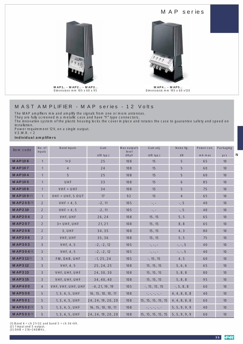
MAST AMPLIFIER - MAP series - 12 VoltsThe MAP amplfiers mix and amplify the signals from one or more antennas.They are fully screened in a metallic case and have “F” type connectors.The innovative system of the plastic housing locks the cover in place and rotates the case to guarantee safety and speed oninstallation.Power requirement 12V, on a single output.V.S.W.R. < 2Individual amplifiers
MAP4.. - MAP5..Dimensionis mm 105 x 60 x120
MAP1.. - MAP2.. - MAP3..Dimensions mm 105 x 60 x 95
MAP108
MAP107
MAP104
MAP105
MAP106
MAP109(2)
MAP205(1)
MAP210
MAP204
MAP207
MAP208
MAP206
MAP303
MAP304(1)
MAP311(3)
MAP312
MAP313
MAP315
MAP400
MAP500
MAP501
MAP502(1)
MAP503(1)
No. ofinputs
Band inputs Gain
(dB typ.)
Max output’sleveldBµV
Gain adj.
(dB typ.)
Noise fig.
dB
Power con.
mA max
Packaging
pcs
1 1+3 25 108 15 5 65 10
1 4 24 108 15 5 60 10
1 5 25 108 15 5 60 10
1 UHF 33 108 15 6 85 10
1 VHF + UHF 34 108 15 5 75 10
1 VHF + UHF, 5 OUT 17 92 15 4 65 10
2 VHF + 4, 5 -2, 11 105 -, - -, 5 40 10
2 VHF + 4, 5 -2, 11 105 -, - -, 5 40 10
2 VHF, UHF 26, 24 108 15, 15 5, 5 65 10
2 3+ UHF, UHF 21, 21 108 15, 15 8, 8 65 10
2 3, UHF 34, 35 108 15, 15 4, 3 80 10
2 VHF, UHF 35, 36 108 15, 15 5, 5 75 10
3 VHF, 4, 5 -2, -2, 12 105 -, -, - -, -, 5 40 10
3 VHF, 4, 5 -2, -2, 12 105 -, -, - -, -, 5 40 10
3 FM, DAB, UHF -1, 25, 24 105 -, 15, 15 4, 5 60 10
3 VHF, 4, 5 25, 24, 25 108 15, 15, 15 5, 6, 6 65 10
3 VHF, UHF, UHF 24, 30, 30 108 15, 15, 15 5, 8, 8 80 10
3 VHF, UHF, UHF 34, 40, 40 108 15, 15, 15 5, 8, 8 95 10
4 VHF, VHF, UHF, UHF -4, 21, 19, 19 105 -, 15, 15, 15 -, 5, 8, 8 60 10
5 1, 3, 4, 5, UHF 16, 15, 10, 10, 11 108 -, -, -, -, - 4, 4, 8, 8, 8 40 10
5 1, 3, 4, 5, UHF 24, 24, 19, 20, 20 108 15, 15, 15, 15, 15 4, 4, 8, 8, 8 60 10
5 1, 3, 4, 5, UHF 16, 15, 10, 10, 11 108 -, -, -, -, - 5, 5, 9, 9, 9 40 10
5 1, 3, 4, 5, UHF 24, 24, 19, 20, 20 108 15, 15, 15, 15, 15 5, 5, 9, 9, 9 60 10
Item code
(1) Band 4 = ch 21÷32 and band 5 = ch 36÷69.(2) 1 input and 5 output.(3) DAB = 216÷240MHz.
N
003_040 atennas e mastheads 23-09-2004 16:54 Pagina 35

MAP series
36
MAST AMPLIFIER - MAP series - 24VoltsThe MAP amplfiers mix and amplify the signals from one or more antennas.They are fully screened in a metallic case and have “F” type connectors.The innovative system of the plastic housing locks the cover in place and rotates the case to guarantee safety and speed oninstallation.Power requirement 24V, on a single output.V.S.W.R. < 2Individual amplifiers
MAP4.. - MAP5..Dimensions mm 105 x 60 x120
MAP1.. - MAP2.. - MAP3..Dimensions mm 105 x 60 x 95
MAP102
MAP103
MAP201
MAP202
MAP209
MAP300
MAP306
MAP314
MAP402
Band Gain
(dB typ.)
OutputleveldBµV
Gain adj.
(dB typ.)
Noise figure
dB
Powerconsumption
mA max
Packaging
pcs
UHF 33 15 108 6 70 10
VHF + UHF 34 15 108 5 70 10
3, UHF 34, 35 15, 15 108 4, 3 75 10
VHF, UHF 35, 36 15, 15 108 5, 5 70 10
VHF, UHF 26, 24 15, 15 108 5, 5 70 10
VHF, UHF, UHF 34, 40, 40 15, 15, 15 108 5, 8, 8 95 10
VHF, 4, 5 34, 32, 34 15, 15, 15 108 5, 6, 6 80 10
VHF, UHF, UHF 24, 30, 30 15, 15, 15 108 5, 8, 8 80 10
VHF, 4, 5, UHF 34, 41, 41, 42 15, 15, 15, 15 108 5, 8, 8, 8 90 10
Item code
003_040 atennas e mastheads 23-09-2004 16:54 Pagina 36

37
MULTI-INPUT MAST AMPLIFIERS - JK seriesTotally shielded metal case with “F” type connectors. Power supply: +12Vdc negative ground. For masts up to Ø 60mm.To mix and amplify signals from several groups of antennas.Power supplied through coax cable: 1 mixed output. Gain adjustment (20dB) with independent attenuators.V.S.W.R. ≤ 2.
Separate VHF and UHF amplification.
JK …Dimensions mm 100 x 56 x 128
JK6QR345(3)
JK6RPUU
JK6RPUU0(1)
JK6RP45
JK6RP45S(2)
JK6R1345U
JK6R1345US(2)
100
75
75
75
75
75
75
Bands Gain (reg.)
dB
Noise figure
≤ dB
Output leveldBµV
b1 b2 UHF
Gainadjustment
dB
Consumption
mA
Packaging
pcs
1
3
3
3
3
5
5
3+4+5
1+3,UHF,UHF
1+3,UHF,UHF
1+3,4,5
1+3,4,5
1,3,4,5,UHF
1,3,4,5,UHF
19,27,26
20+20,29,29
20+20,29,29
20+20,29,31
20+20,29,31
21,19,28,28,28
21,19,28,28,28
4,7,6
4+4,7,7
4+4,7,7
4+4,5,5
4+4,5,5
3,3,7,8,7
3,3,7,8,7
108 112 112
105 108 112
105 108 112
105 108 112
105 108 112
105 108 112
105 108 112
x,x,x
x,x,x
x,x,x
x,x,x
x,x,x
x,x,x,x,x
x,x,x,x,x
Item code No. ofinput
5
5
5
5
5
5
5
(1) In b. 1 input also passes channel C.(2) Letter S shows that band is only for channels 21-32, 470÷565 MHz b. 5 is = 590÷862 MHz (channels 36 - 69).(3) Q in model number indicates one input for bands 3, 4, and 5 with gain adjustment for each band.
EK5/... - EK6/..Dimensions mm 112 x 52 x 112
MULTI-BAND MAST AMPLIFIERS - EK seriesWeatherproof plastic housing. Suitable for mast mounting ∅ 42mm max. For coupling and amplifying the signals from severalgroups of antennas. Shielded saddle and clamp terminals for improved isolation between inputs. Powered by coaxialdownlead. One coupled output. V.S.W.R. ≤ 2. Suitable for pre-amplifiers. 12Vdc.Separate attenuators with adjustable attenuation (20dB).
Separate VHF and UHF amplification.
No. ofinput
Inputs bands Gain
dB
Noise figure
≤ dB
Output level
dBµV
Packaging
pcs
Consumption
mA
Gainadjustment
dB
6060606060606060
1010101010101010
13333355
3+4+51+3,U,U
1+3+C,U,U1+3,4,51+3,4,5
1,3,4,5,U1+C,3,4,5,U
1,3,4,5,U
20,27,2521+19,25,2521+19,25,2521+19,27,2821+19,27,28
23,18,25,25,2523,18,25,25,2523,18,25,25,25
4,5,53.5,8,83.5,8,8
3.5,4.5,53.5,4.5,55,5,8,8,85,5,8,8,85,5,8,8,8
108,110,110106+108,110,110106+108,110,110106+108,108,110106+108,108,110
103,108,108,108,108103,108,108,108,108103,108,108,108,108
x,x,xx,x,xx,x,xx,x,xx,x,x
x,x,x,x,xx,x,x,x,xx,x,x,x,x
EK6/Q-345EK6RPUUEK6RPUU0(1)
EK6RP45EK6RP45S(1)
EK6R1345UEK6R1345U0EK6R1345US(1)
Multiband mast amplifiersJK series and EK series
003_040 atennas e mastheads 23-09-2004 16:54 Pagina 37

INDOOR BROADBAND AMPLIFIERSMAINS POWEREDPower supply required: 220-230V~ - 50Hz.Insulation: class II.Operating temperature: -10°C ÷ +55°C.240V ± 10% by special order. For all TV bands (47÷862MHz). V.S.W.R. ≤ 2. 1 input - 1 output
No. of transistors
Gain (reg.)dB
Max. outputdBµV
Noise figure≤ dB
Power consumptionW
Packagingpcs
Item code
1,2
With shielded clamps
1,6
3,0
10
10
10
5
5
5
108
108
113
8
19
14 ÷ 34 (20)
1
2
3
ABLA101
ABLA102
ABLA3RT
INDOOR BROADBAND AMPLIFIERSMAINS POWEREDPower supply 220-230V~ - 50/60Hz. Insulation: class II. Operating temperature: -10°C ÷ +55°C.It can be placed either on the back of the TV set, a table or fixed to the wall.For table and wall mounting remove the hook on the bottom. «F»-type input and output connectors. Totally shielded RF section to prevent interferences.
GaindB
No. of outputs
Output leveldBµV
Noise figure≤ dB
BandMHz
V.S.W.R.≤
Power consumptionW
Packagingpcs
7÷22 1 110 5 47÷862 2 3,5 1JA21R
TV+SAT BROADBAND AMPLIFIERS (5÷2400MHz)TV and SAT amplifiers with V.S.W.R. charateristics and typical noise figures of a professional product, to be used asamplifiers for single SAT systems, Multiswitch and single IF distribution.Passes the D.C. 22KHz and DiSEqC between input and output.Power supply: 220-230V~ - 50/60Hz.Insulation class: II.Operating temperature: -10 ÷ 55°C.Totally shielded RF section to prevent interferences.
GaindB
No. of outputs
Output leveldBµV
Noise figure≤ dB
BandMHz
V.S.W.R.≤
Power consumptionW
Packagingpcs
13 1 115 7 5÷2400 1,5 3,5 1JAX13DC
Broadband amplifiers
38
ABLA101-102-3RTDimensions mm 105 x 62 x 53
JAX13DC - JA21RDimensions mm 92 x 49 x 109
003_040 atennas e mastheads 23-09-2004 16:54 Pagina 38
Multi-socket range amplifiers
39
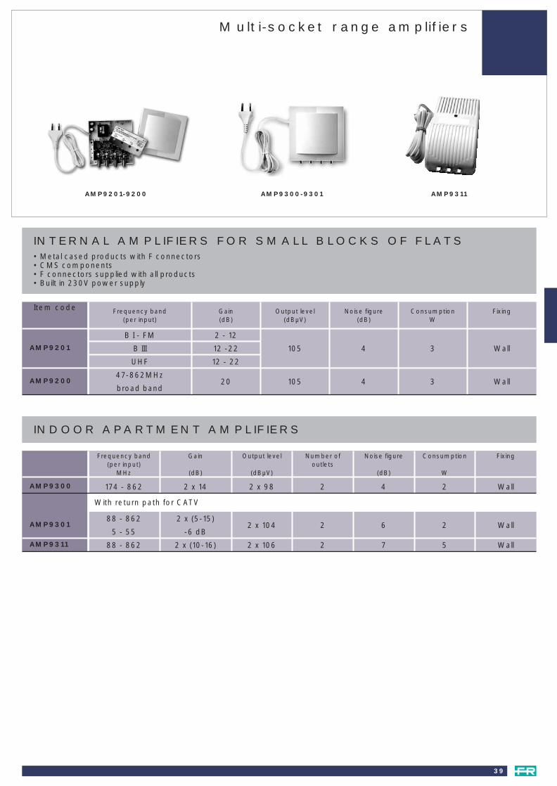
AMP9201-9200 AMP9300-9301
INTERNAL AMPLIFIERS FOR SMALL BLOCKS OF FLATS• Metal cased products with F connectors• CMS components• F connectors supplied with all products• Built in 230V power supply
AMP9201
AMP9200
B I - FM
B III
UHF
47-862MHz
broad band
2 - 12
12 -22
12 - 22
20
105
105
4
4
3
3
Wall
Wall
Item code Frequency band(per input)
Gain(dB)
Output level(dBµV)
Noise figure(dB)
ConsumptionW
Fixing
INDOOR APARTMENT AMPLIFIERS
AMP9300 174 - 862 2 x 14 2 x 98 2 4 2 Wall
88 - 862
5 - 55
2 x (5-15)
-6 dB2 x 104 2 6 2 WallAMP9301
88 - 862 2 x (10-16) 2 x 10⁶ 2 7 5 WallAMP9311
Frequency band(per input)
MHz
Gain
(dB)
Output level
(dBµV)
Number ofoutlets
Noise figure
(dB)
Consumption
W
Fixing
With return path for CATV
AMP9311
003_040 atennas e mastheads 23-09-2004 16:54 Pagina 39

Power supplies AM series - PSU series - AL series
40
POWER SUPPLIES - AM seriesThe new AM series is an effective answer to all power supply requirements that may arise in every aerial installation.Models available: 12Vdc, 50mA and 100mA.The new AM series is designed to meet the strictest safety requirements and to shut down in case of a short circuit.Value for money, the wide range of models and the look of the new AM series makes it the best solution for thoseinstallations where the overall quality is as important as the price.Input 220-230V~ - 50Hz.Insulation: class II.Operating temperature: -10°C ÷ +55°C.
Output voltageV
PowermA
Outputs Packingingpcs
PSU411
PSU412
PSU341
PSU342
Item code
AM …Dimensions mm 50 x 87 x 46
AL50SDimensions mm 52 x 87 x 84
PSU...Dimensions mm 92 x 49 x 109
Power supply 12Vdc - 50mA - 1 output - Pack. 20pcs
Power supply 12Vdc - 100mA - 1 output - Pack. 20pcs
Power supply 12Vdc - 100mA - 2 output - Pack. 20pcs
AM50N
AM100N
AM102N
POWER SUPPLIES - PSU seriesSTABALIZEDInput: 220-240V - 50/60Hz. Class: II isolationTemperature of operation: -10° C +55 °CWith short circuit protection.New plastic case suitable for fixing to a table or a wall.Low energy consumption “F” type connectors on the input and output.Componets are screened to prevent any RF inteferences.
12 200 1 1
12 200 2 1
24 100 1 1
24 100 2 1
POWER SUPPLIES - AL seriesInput 220 - 50Hz. Output 12V continous. - Class II isolation.Temperature of operation: -10° C +55 °CWith short circuit protection and self reset.Max current 42mA connection.
(1) With IEC Connector’s Type 9.5mm
Output’s tensionV
PowermA
Outputs Packingingpcs
AL50S(1) 12 42 1 1
003_040 atennas e mastheads 23-09-2004 16:54 Pagina 40

TV and SAT headends
COMPACT LINE RANGEAnalogue satellite processing headend
SMATV HEADEND - K SERIESGeneral featuresRemote control unit - converterMATV headends - channel amplifiersDTT channel amplifiers - Broadband amplifiersSMATV digital receiversDTT receiver - QPSK-QAM transmodulatorModulatorsConverters - AmplifiersIF-IF conversionK series accessories
HEADLINE RANGEQPSK receiverAnalogue satellite processor - FM filtersModulators – Multi-modulatorsAccessories
MULTIBAND AMPLIFIERSJH-JB seriesMBX seriesDigital multiband amplifiersDigital filter equalisers Indoor modulatorsHeadend amplifiers
Page 42-43
444546474849505152
53-54
55565758
596061626364
Fracarro has all the solutions for analogue and digital processingin medium, large or high end professional systems.Ready for future technology.Available in modular or compact headend
041_064 headends 23-09-2004 16:55 Pagina 41

42
Item code SIG9306UNBANDWITH:
Satellite input 920 - 2150MHz, 1 inputRF input 47 - 860MHzOutput 470 - 862MHz
COMPATIBILITY:TV standards SECAM L, PAL B/G D/K I, NTSC MAudio noise reduction Compatible with PANDA
CONNECTORS:Connectors FDecoder output / input DIN - 7 pin
SATELLITE INPUT:Entry level 49 to 79dBµVImpedance 75OhmIF filter 27MHz (-3dB)
DECODER OUTPUT / INPUT:Base band output voltage 1V ppImpedance 75OhmFrequncy range 25Hz to 10MHzVideo output voltage 1V ppImpedance 75OhmFrequency range 25Hz to 5MHzSignal to noise (with C/N 14dB) 49dB typ.C/KU band positive/negative videoVideo deviation (programmable) 13.5 / 16 / 19 / 22.5MHz/VVideo output modality RAW / Video B.Base / Normal / Inverted
AUDIO:Sub carriers frequency 5.5 to 9.5MHzBandwidth filter 130kHz, 180kHz, 280kHz, 330kHz, 380kHz, 400kHzDeemphasis 50µs, 75µs, j17Modes 2 channels independent tuningBandwidth 30 to 15000HzLevel adjustment (programmable) -5, -4, -3, -2, -1, 0, +1, +2, +3, +4, +5, step 1.25dB
MODULATOR:Frequency range 470 - 860MHzModulation Double side bandFrequency stability < ± 70kHzOutput level adjustment 90 to 100dBµV typ., adjustable via software for every receiverFlatness ± 2.5dBImpedance 75OhmTerrestrial coupling loss 2dB typ.
GENERAL:Operating voltage 185 to 264Vac 50/60HzLNB power supply 0/14/18V - 0/22kHz on every inputLNB consumption 400mA totals max.Operating temperature -5 to +45°CDimensions 370x240x150mm
COMPACT HEADEND FOR 6 ANALOGUE CHANNELSCompact headend for the reception and distribution of 6 analogue satellite channels. Demodulates 6 analogue channels and remodulates them into RF band: VHF band (SIG9306VN) or UHF (SIG9306UN) band. Compact headend includes 6 analoguereceivers, 6 A/V modulators, 6-way combiner with existing TV signal mixing, power supply unit and programming unit.A/V output are available to connect optional decoder for encrypted channel receiving. Wall and floor installation possible.Earth bound screw. EN50083 compliant.KEY POINTSEasy to install, in one box are included: • Power supply • 6 analogue receivers for free-to-air channels
• 6 A/V modulators • Combiner to mix 6 RF channels• Final amplifier 100dBµV • Programming unit with 2 rows backlighted display
Every single receiver can generate 14 or 18V also 22KHz tone, suitable to feed LNB or to control multiswitch output, adjustable viasoftware; protected access via pin code; heat dissipation by natural convection, no need to have fans, maintenance costs reduction.
new
N
SIG9306UN
Compact line rangeAnalogue satellite processing headend
041_064 headends 23-09-2004 16:55 Pagina 42

43
Item code SIG9306VNBANDWITH:
Satellite input 920 - 2150MHz, 1 inputRF input 47 - 860MHzOutput 146 - 430MHz
COMPATIBILITY:TV standards SECAM L, PAL B/G D/K I, NTSC MAudio noise reduction Compatible with PANDA
CONNECTORS:Connectors FDecoder output / input DIN - 7 pin
SATELLITE INPUT:Entry level 49 to 79dBµVImpedance 75OhmIF filter 27MHz (-3dB)
DECODER OUTPUT / INPUT:Base band output voltage 1V ppImpedance 75OhmFrequncy range 25Hz to 10MHzVideo output voltage 1V ppImpedance 75OhmFrequency range 25Hz to 5MHzSignal to noise (with C/N 14dB) 49dB typ.C/KU band positive/negative videoVideo deviation (programmable) 13.5 / 16 / 19 / 22.5MHz/VVideo output modality RAW / Video B.Base / Normal / Inverted
AUDIO:Sub carriers frequency 5.5 to 9.5MHzBandwidth filter 130kHz, 180kHz, 280kHz, 330kHz, 380kHz, 400kHzDeemphasis 50µs, 75µs, j17Modes 2 channels independent tuningBandwidth 30 to 15000HzLevel adjustment (programmable) -5, -4, -3, -2, -1, 0, +1, +2, +3, +4, +5, step 1.25dB
MODULATOR:Frequency range 146 - 430MHzModulation Double side bandFrequency stability < ± 70kHzOutput level adjustment 90 to 100dBµV typ., adjustable via software for every receiverFlatness ± 2.5dBImpedance 75OhmTerrestrial coupling loss 2dB typ.
GENERAL:Operating voltage 185 to 264Vac 50/60HzLNB power supply 0/14/18V - 0/22kHz on every inputLNB consumption 400mA totals max.Operating temperature -5 to +45°CDimensions 370x240x150mm
FILTERED BAND COUPLERS4 input couplers to create an 18 channel headend. Input filtering to improve C/N.Connectors F. Transition losses 2.5dB. Dimensions 122x67x42mm.
Input 1
MHz
Input 2
MHz
Input 3
MHz
Outputs
MHz
Input 4
MHz
Impedance
Ohms
PAS0322001
PAS0322011
118-209 (03-19)
118-446
230-326 (011-023)
470-582
75
75
470-862 (021-069)
750-862
118-862
118-862
350-446 (027-038)
606-726
new
N
SIG9306VN
Compact line rangeAnalogue satellite processing headend
041_064 headends 23-09-2004 16:55 Pagina 43

44
K SERIESMODULAR SYSTEMS FOR MATV/SMATV SYSTEMSThe design targets of the K series are:
• Easy installation and maintenance
• Flexibility in the unit / headend composition (in particular with reference to the integration between traditional TV, satelliteTV and satellite IF).
• Solid and inexpensive, but without compromising performance.
• Ready for future product ranges.
• In compliance with all European and international regulations in force, including shielding and electromagnetic compatibility( mark, according to 89/336/EEC directives mod. 93/68/EEC).
The main features of K series products are:
• Fixing to standard DIN bar, which provides good mechanical strength and the maximum density when assembling theheadends. It also allows the use of a very wide range of standard accessories available on the market.
• Single voltage feed (12V, negative). A local power supply is provided where necessary. It is quick and easy to replace andkeeps spare parts down to a minimum.
• All modules have a solid mechanical structure. In particular, channel filters - where dimensional stability and surfaceconductivity are critical features - are in die-cast and small silver plated boxes.
• For RF connections, all modules use “F” connetors with quick fit interconnection bridges.
• Adjacent channel distribution is possible thanks to the channel filters selectivity together with the vestigial sideband (VSB)modulators used in satellite receivers.
• Channel filters have a uniform gain (about 10dB) both in VHF and in UHF and a 90dBµV, output level guaranteeing anoptimum overall picture quality even with weak signals.
• The range of products for satellite reception includes an active double splitter - with D.C. and 22KHz burst / generator (nosplitters and external power supplies are required) - and an IF satellite amplifier with TV mixing, which, combined with thenew passive products, give san IF distribution systems compatible with digital signals.
• For the digital system, we have created a new range of products for the reception of free to air digital channel and for thedistribution of digital signals with QPSK QAM conversion.
• 19 inch rack installation possible.
Active filters for digital terrestrial have been developed using the KF and K120 active channel filters. These have beencalibrated especially for the distribution of new COFDM modulated signals.
SMATV headends - K series
041_064 headends 23-09-2004 16:55 Pagina 44
45
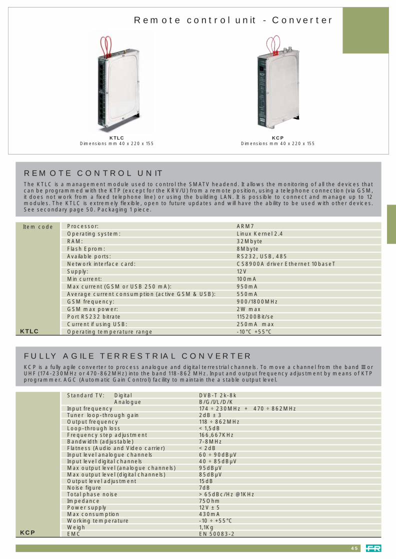
KCPDimensions mm 40 x 220 x 155
FULLY AGILE TERRESTRIAL CONVERTERKCP is a fully agile converter to process analogue and digital terrestrial channels. To move a channel from the band III orUHF (174-230MHz or 470-862MHz) into the band 118-862 MHz. Input and output frequency adjustment by means of KTPprogrammer. AGC (Automatic Gain Control) facility to maintain the a stable output level.
KTLCDimensions mm 40 x 220 x 155
REMOTE CONTROL UNITThe KTLC is a management module used to control the SMATV headend. It allows the monitoring of all the devices thatcan be programmed with the KTP (except for the KRV/U) from a remote position, using a telephone connection (via GSM,it does not work from a fixed telephone line) or using the building LAN. It is possible to connect and manage up to 12modules. The KTLC is extremely flexible, open to future updates and will have the ability to be used with other devices.See secondary page 50. Packaging 1 piece.
Item code Processor: ARM7Operating system: Linux Kernel 2.4RAM: 32MbyteFlash Eprom: 8MbyteAvailable ports: RS232, USB, 485Network interface card: CS8900A driver Ethernet 10baseTSupply: 12VMin current: 100mAMax current (GSM or USB 250 mA): 950mAAverage current consumption (active GSM & USB): 550mAGSM frequency: 900/1800MHzGSM max power: 2W maxPort RS232 bitrate 115200Bit/seCurrent if using USB: 250mA max Operating temperature range -10°C +55°CKTLC
Standard TV: Digital DVB-T 2k-8kAnalogue B/G/I/L/D/K
Input frequency 174 ÷ 230MHz + 470 ÷ 862MHz Tuner loop-through gain 2dB ± 3Output frequency 118 ÷ 862MHzLoop-through loss < 1,5dBFrequency step adjustment 166,667KHzBandwidth (adjustable) 7-8MHzFlatness (Audio and Video carrier) < 2dBInput level analogue channels 60 ÷ 90dBµVInput level digital channels 40 ÷ 85dBµVMax output level (analogue channels) 95dBµVMax output level (digital channels) 85dBµVOutput level adjustment 15dBNoise figure 7dBTotal phase noise > 65dBc/Hz @1KHzImpedance 75OhmPower supply 12V ± 5Max consumption 430mAWorking temperature -10 ÷ +55°CWeigh 1,1KgEMC EN 50083-2KCP
Remote control unit - Converter
041_064 headends 23-09-2004 16:55 Pagina 45

Gain (adj.)
dB
CHANNEL AMPLIFIERSChannel amplifiers comprising 5 resonant circuits for VHF modules and 4 for the UHF modules. Excellent selectivity to allowthe distribution of adjacent channels. An SMD amplification card ensures a high degree of reliability and repeatability.Insensitive to static discharge and temperature change stability has been taken in to accont during the design phase.Operating temperature: from –20° to +60°C.Packaging 1pc.
DAB AMPLIFIERPackaging 1pc.
Item code
MATV headends - Channel amplifiers
KF/.. - K120/.. - KF/DABDimensions mm 32 x 129 x 86
9 (45)9 (45)9 (45)7 (30)
11 (35)11 (35)
20 @ 12V20 @ 12V20 @ 12V20 @ 12V38 @ 12V38 @ 12V
35–
45404242
5–55
1010
9–
10101616
35–
42404646
749
101010
E2÷E4FM
E5÷E12S11÷S20S21÷S38E21÷E69
Powerconsumption
max mA
FrequencyNoisefigure typ.
dB
Max. outputleveldBµV
Return lossoutput
dB
Return lossinputdB
Selectivitystandard B/G(1)
PAn-2 PAn-1 PVn+1 PVn+2
101510101210
151510101210
939095959595KF/..
Gain (adj.)
dB
45 (40) 40 (40) 45 (40)45 (30)45 (30)45 (30)
35-
40354242
5-55
1010
9-
10101616
35-
44404646
121112120120120120
8591099
E2÷E4FM
E5÷E12S11÷S20S21÷S38E21÷E69
180 @ 12V200 @ 12V180 @ 12V200 @ 12V200 @ 12V200 @ 12V
Powerconsumption
max mA
FrequencyNoise figuretyp.dB
Output level
dBµV
Selectivitystandard B/G(1)
PAn-2 PAn-1 PVn+1 PVn+2
K120/..
Gain (adj.)dB
Return loss inputdB
Return loss outputdB
Max. output leveldBµV
BandwidthMHz
Power consumptionmax mA
14 (45) 10 10 105 217÷230 20 @ 12VKF/DAB
(1) Possibility to adjust different standard on request.
120 dBµV OUTPUT CHANNEL AMPLIFIERSChannel amplifiers comprising five resonant circuits for the VHF modules and 4 for the UHF modules. Excellent selectivity toallow the distribution of adjacent channels. The SMD amplification card ensures a high degree of reliability and repeatability.Insensitive to static discharge and temperature change stability has been taken in to accont during the design phase.Operating temperature: from –20° to +60°C.Packaging 1pc.
46
041_064 headends 23-09-2004 16:55 Pagina 46

Gain (adj.)
dB
DISTRIBUTION OF DTT SIGNALThe Fracarro K series has been improved with two new single-channel amplified filters, KF/..DT and K120/..DT for thedistribution of Digital Terrestrial Television signals. These modules can be used to update existing systems to receive DTTsignals without disruption to the existing system. Due to the high selectivity of the filter, the frequency response and theoutput level adjustment, it is simple to combine these modules with other modules giving a clean output signal. Each modulehas self-mixing and self-demixing capability, with a very low loss, that simplifies the installation of the distribution system.Packaging 1pc.
Max inputleveldBµV
CHANNEL AMPLIFIER WITH AUTOMATIC GAIN CONTROL(AGC). OUTPUT POWER 120dBµVChannel amplifiers with 5 resonant circuits for VHF and UHF bands. Their selectivity allows the distribution of adjacentchannels. The automatic gain control gives a constant output level even with a varying input level. Essential in conditionswhere the signal reception level may vary also useful in CATV networks with cascaded line amplifiers and for the inputs offibre optic links. Gain: 45dB. Max output level: 120dBµV.Working temperature: -10° ÷ +55°C.Packaging 1pc.
DTT channel amplifiers - Broadband amplifiers
Item code
K120A/..Dimensions mm 32 x 129 x 86
Powerconsumption
max mA
90
95
95
5
5
12
9
10
49
110 ÷ 120
110 ÷ 120
110 ÷ 120
25
30
30
8
9
10
E2÷E4
E5÷E12
E21÷E69
210 @ 12V
210 @ 12V
210 @ 12VK120A/..
(1) it is possible to adjust the amplifier to different Standard on request.
Operativechannels
Noisefigure
dB
AGC Dynamic(max)
dB
Output’slevel Adj.
dBµV
SelectivityB/G standard(1)
PAn-2 PVn+1
KF/...DT - K 120/...DTDimensions mm 32 x 129 x 86
Powerconsumption
max mA
Channels
11 (35)
45 (30)
38 @ 12V
200 @ 12V
KF/...DT
K120/...DT
> 38
> 38
> 8
> 8
> 11
> 11
> 42
> 42
21÷69
21÷69
10
10
10
10
95
115
Return lossinputdB
Return lossoutput
dB
Output levelmax.dBµV
NF
dB
10
9
Selectivity
SCn-2 SCn-1 VCn+1 VCn+2
Bandwidth
MHz
Gain (adj.)
dB
Return lossinputdB
Return lossoutput
dB
Output levelmax.dBµV
Noise figure
dB
Powerconsumption
max mA
BAND AMPLIFIERSThese are provided with three channel traps to equalise the input channels or to eliminate unwanted channels. Each trap has15dB attenuation and can be tuned by the installer.The KFB4 and KFB5 can be placed along side the KF filters…/ taking care not to tune to future channel requirements. They use the same mechanical structure as the K series, with F connectors and a self mixed output.Packaging 1pc.
470÷590
606÷862
13 (20)
11 (20)
10
10
15
15
100
100
4
4
130 @ 12V
130 @ 12V
KFB4
KFB5
47
041_064 headends 23-09-2004 16:55 Pagina 47

48
SMATV digital receivers
KDFAV - KDFU - KDFVDimensions mm 74 x 188 x 112
Item code KDFU KDFV KDFAV
Front-end satelliteInput frequency range 950-2150MHz 950-2150MHz 950-2150MHzInput level -65÷-25dBm -65÷-25dBm -65÷-25dBmBandwidth 36MHz 36MHz 36MHzDemodulation QPSK ETS 300421 QPSK ETS 300421 QPSK ETS 300421FEC 1/2, 2/3, 3/4, 5/6, 7,8 1/2, 2/3, 3/4, 5/6, 7,8 1/2, 2/3, 3/4, 5/6, 7,8
RF outputOutput frequency 470÷865MHz 170÷260MHz –Channels 21÷69 E5÷E12 + S11÷S14 –Output channel configuration dip-switch –Output level 90dBµV ± 2dB typ. - reg. 0÷20dB –Input automixing 40÷865MHz –Automixing loss -1dB ± 0,2dB –Audio level adjustable –Video level adjustable –Connectors F –
Video decoderMPEG2 – ISO-IEC 138 18-1 TS DemuxVideo format – 4:3, 16:9
Audio decoderBit Rate Audio – > 384 kbit/sec ISO/IEC 11172-3Audio format 1/2, 2/3, 3/4, 5/6, 7/8 stereo
Consumption 800 mA @ + 12 V D.C. 800 mA @ + 12 V D.C.Dimensions 74 x 188 x 112mm 74 x 188 x 112mm
QPSK DIGITAL RECEIVER FOR SMATV APPLICATIONQpsk digital satellite receiver PAL to receive all free to air satellite channels. Available in three different versions:• KDFU satellite receiver with UHF modulator built-in• KDFV satellite receiver with VHF modulator built-in• KDFAV satellite receiver without modulator. A/V output to connect external modulators. Stereo audio available.It is possible to receive SCPC programmes.Automatic PID updating. Packaging 1 pc.
041_064 headends 23-09-2004 16:55 Pagina 48
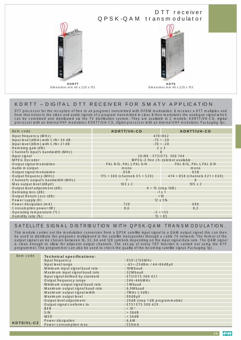
49
KDTSDimensions mm 40 x 220 x 155
SATELLITE SIGNAL DISTRIBUTION WITH QPSK-QAM TRANSMODULATION.This module carries out the modulation conversion from a QPSK satellite input signal to a QAM output signal; this can thenbe used to distribute the programs multiplexed in the satellite transponder through a cable TV network. The format of theoutput signal can be chosen between 16, 32, 64 and 128 symbols depending on the input signal data rate. The QAM signalis clean enough to allow for adjacent output channels. The set-up of every TDT function is carried out using the KTPprogrammer. The programmer can also be used to check the quality of the incoming satellite signal. Packaging 1pc.
Item code Technical specifications:Input frequency : 950÷2150MHzInput level range : -65÷-25dBm / 44÷84dBµVMinimum input signal baud rate : 10MbaudMaximum input signal baud rate : 32MbaudInput signal defined by standard : ETSI ETS 300 421Output frequency range : 246÷446MHzMinimum output signal baud rate : 1 MbaudMaximum output signal baud rate : 6,9MbaudMaximum output signal width : 7MHz (-3dB)Maximum output level : 90dBµVOutput level adjustment : 20dB (step 1 dB programmable)Output signal conforms to : ET51 ET5 300 429BER : < 10-9
S/N : > 38dBMER : > 36dBPower dissipation : 6,6WPower consumption max : 550mAKDTS/VL-C2
DTT receiverQPSK-QAM transmodulator
KDRTTDimensions mm 40 x 220 x 155
KDRTT – DIGITAL DTT RECEIVER FOR SMATV APPLICATIONDTT processor for the reception of free to air programs transmitted with OFDM modulation. It receives a DTT multiplex andfrom that extracts the video and audio signals of a program transmitted in clear. It then modulates the analogue signal whichcan be combined and distributed via the TV distribution system. They are available in 2 models: KDRTT/VH-CD, digitalprocessor with an internal VHF modulator; KDRTT/UH-CD, digital processor with an internal UHF modulator. Packaging 1pc.
Item code KDRTT/VH-CD KDRTT/UH-CDInput frequency (MHz) 470÷862Input level (dBm) with C/N= 34 dB -73 ÷ -20Input level (dBm) with C/N= 21 dB -70 ÷ -20Demixing gain (dB) 2 ± 3Channel’s input’s bandwidth (MHz) 8Input signal 2K/8K - ETSI ETS 300 744MPEG Decoder MPEG-2 free ch-.teletext availableOutput signal modulation PAL B/G, PAL I, PAL D/K PAL B/G, PAL I, PAL D/KAudio in output mono monoOutput signal modulation DSB DSBOutput frequency (MHz) 175 ÷ 300 (channels E5 ÷ S20) 474 ÷ 858 (channels E21 ÷ E69)Channel’s output’s bandwidth (MHz) 7 8Max output level (dBµV) 103 ± 2 105 ± 2Output level adjustment (dB) 0 ÷ 15 (step 1dB) Demixing loss (dB) -1 ± 1Output Return Loss (dB) >10Power supply (V) 12 ± 5%Power dissipation (mA) 720 690Consumption power (W) 8,6 8,3Operating temperature (°C) -5 ÷ +55Humidity ratio (%) 15 ÷ 85
041_064 headends 23-09-2004 16:55 Pagina 49

Modulators
VESTIGIAL SIDE BAND MODULATORAudio Video vestigial side band modulator with built in tracking filter. Two different models allow the distribution of channelsin VHF band (E05÷S30) and in the UHF band (E21÷E69). Three versions for each model are available: PAL B/G mono, PALB/G stereo and multistandard mono. RCA connectors on Audio and video input. F connectors on selfmixing outputs.
KCMV - KCMUDimensions mm 63 x 175 x 103
50
Item code KCMV KCMV/S KCMV/M KCMU KCMU/S KCMU/M
Composite video signal input Impedance 75OhmLevel 1Vpp
Audio inputs Left and Right Impedance 10KOhmNominal input level 0,5Vrms
Standards B/G B/G N/H/I/D/K/L B/G B/G N/H/I/D/K/LStereo A2 Stereo A2 Stereo A2
Sub-carriers frequencyB/G standard mono or Left carrier 5,50MHz 5,50MHz – 5,50MHz 5,50MHz 5,50MHz
Right carrier – 5,74MHz – – 5,74MHz –H standard 5,50MHz 5,50MHzL D/K standards 6,50MHz 6,50MHzI standard 6.00MHz 6.00MHzN standard 4,50MHz 4,50MHzVision / sound carrier power ratioN standard – – 10dB – – 10dBH standard – – 14dB – – 14dBI standard – – 14dB – – 14dBD/K standard – – 13dB v – 13dBL standard – – 8dB – – 8dBB/G standard: Mono (5.5MHz) 14dB 14dB – 14dB 14dB –
Stereo (5.742MHz) – 21dB – – 21dB –Modulation for 1 kHz, 0,5Vrms on Audio Inputs B/G, 49kHz 49kHz 49kHz 49kHz 49kHz 49kHz
N (FM) <42kHz <42kHzH 44kHz 44kHz
I, D/K (FM) >47kHz >47kHzL (AM) 80% 80%
Modulation depth for 1Vpp Video input D/K, I, B/G standards 80 % typ 80 % typ 80 % typ 80 % typ 80 % typ 80 % typ
L standard 90÷97% 90÷97%Frequency band 174 ÷ 382MHz 470 ÷ 862MHz Channel E5 ÷ S30 E21 ÷ E69 Output level 90dBµV +/- 2dBLevel adjustment 15dB by 1dB stepsThrough loss < 1,5dB @ 860MHz C/N inside the channel at Videocarrier + 2,7 MHz – BW 5Mz 58dB 58dB 58dB 57dB 57dB 57dBC/N in channel N+/- 1 65dB 65dB 65dB 63dB 63dB 63dBC/N in channel N+/- 2 66dB 66dB 66dB 65dB 65dB 65dBSpurious rejection > 54 dBPower voltage 12 VdcPower consumption 350mA 450mA 350mA 330mA 440mA 330mAOperating temperature - 10°C ÷ + 55°CStorage temperature - 10°C ÷ + 80°CEMC EN 50083-2
041_064 headends 23-09-2004 16:55 Pagina 50

FINAL PUSH-PULL AMPLIFIERSThe main characteristic of broad band amplifiers with a push-pull configuration, is eliminating second order intermodulation (IM2).This allows the distribution of the entire TV band from 47 to 862MHz, without causing too many distorsions.The separate amplification of the VHF and UHF bands results in the S-band being cut from channel S21 to S38 in order toavoid eventual second order intermodulation problems created by the presence of other channels in the VHF band. In orderto use the whole of the 47MHz to 862MHz band, without problems, including S-band for the distribution of analogue anddigital satellite signals, it is better to use a push-pull technology, as is with professional broad band amplifiers. The amplifiersare provided with one input and one output. They can be installed at the end of the TV and/or SAT modules, to simplify theentire system. The KW33C, KW44C and KW35E are available with a 20dB equaliser which equalises the cable losses in thesystem. The KW35E passes the return channel (5÷30MHz).
Item code
51
Converters - Amplifiers
PROGRAMMABLE CHANNEL CONVERTERSThe KK module is a channel converter for terrestrial analogue TV signals. The filter for the input channel is tuned duringthe manufacturing of the product (the customer has to specify the channel at order). A separate module is used for theoutput channel, typically a KF or a K120 amplified filter (this also has to be specified at time of order).An output filter must be used to remove all the spurious signals produced in the conversion.The conversion is programmed using a KTP.
KK.. - KW5..Dimensions mm 32 x 129 x 86
Input frequency rangeMHz
Channels(2)
Output frequency rangeMHz
Channels(1)
Power consumptionmax mA
Packagingpcs
(1) 20 dB attenuation for the entire band. - (2) 0 - 20 dB equalisation.
47÷68
174÷230
470÷574
574÷702
702÷862
E2÷E4
E5÷E12
E21÷E33
E34÷E49
E50÷E69
470÷862
470÷606
174÷286
174÷286
174÷286
E21÷E69
E21÷E37
E5÷S18
E5÷S18
E5÷S18
120 @ 12V
120 @ 12V
120 @ 12V
120 @ 12V
120 @ 12V
1
1
1
1
1
KK1-U
KK3-4
KK4-3
KK5-3
KK6-3
KW35EDimensions mm 63 x 184 x 107
KW33BDimensions mm 32 x 129 x 86
KW33C - KW44CDimensions mm 63 x 184 x 107
47÷862
47÷862
5÷30 47÷862
47÷862
34 (20)
32 (1)(2)
35 (1)(2)
44 (1)(2)
116
121
125
121
8
9
9
8
300 @ 12V
510 @ 12V
830 @ 12V
550 @ 12V
1
1
1
1
KW33B
KW33C
KW35E
KW44C
Frequency rangeMHz
Gain (adj.)dB
Max. output leveldBµV
Noise figuredB
Power consumptionmax mA
Packagingpcs
RETURN CHANNEL AMPLIFIERSThe KW530 amplifies the return channel 5÷30MHz and mixes the TV signal between 47 and 862MHz. The KW 540 amplifiesthe return channel 5÷40MHz and mixes the TV signal between 54 and 862MHz.
5÷30
47÷862
5÷40
54÷862
20 (20)
– 1,5
20 (20)
– 1,5
105
–
105
–
5
–
5–
30 @ 12V 1
30 @ 12V 1
KW530
KW540
Input frequency rangeMHz
Gain (adj.)dB
Output leveldBµV
Noise figuredB
Power consumptionmax mA
Packagingpcs
041_064 headends 23-09-2004 16:55 Pagina 51

52
SAT AMPLIFIER + TV MIXERAmplifies Satellite IF (950÷2150MHz.) whilst mixing terrestrial TV frequencies of 47÷862MHz. Overcomes the higher lossesexperienced when distributing SAT IF.
AMPLIFIED SAT FILTERSTo filter and amplify the SAT band choose the IF band that contains the required transponders.Three types of filters are available to create different solutions that maybe required.
IF-IF conversion
KX125 - KX125NT - KX125EDimensions mm 32 x 129 x 86
K1150-1570 - K1720-2150K1940-2150 - K2015-2150Dimensions mm 32 x 129 x 86
Item code
950÷215047÷862
950÷215047÷862
38(20) 44(20)-1
35(20) -1
125–
125–
6–6–
310 @ 12V 1
280 @ 12V 1
KX125
KX125NT
950÷215047÷862
38(20) 44(20)-1
125–
6–
310 @ 12V 1KX125E
Input frequency
MHz
Gain (adj.)dB
950 MHz 2150 MHz
Output levelmaxdBµV
Noise figure
dB
Powerconsumption
max mA
Packaging
pcs
1150÷15701720÷21501940÷21502015÷2150
15(15)15(15)15(15)15(15)
90909090
< 5< 5< 5< 5
70 @ 12V70 @ 12V70 @ 12V70 @ 12V
1111
K1150-1570K1720-2150K1940-2150K2015-2150
BandwidthMHz
Gain (adj.)dB
Max. output leveldBµV
FlatnessdBµV
Power consumptionmax mA
Packagingpcs
TRANSPONDER AMPLIFIED SELECTIVE FILTERThe KFT module selects and amplifies a transponder in the band from 950 to 2150MHz. The filter uses K series housing with F connectors and is self-mixing both for input and output.
PROGRAMMABLE IF-IF CONVERTERIF-IF converter with Input loop through to connect different modules to the same polarity. Fully programmable.Remote power available for LNB’s or preamplifiers. KTP ( Universal programmer) is connected with RJ45 Socket to the front panel. To program the converter using a KTP with MINI THORN-DIN it is necessary to use the transition TR DIN-RJ ( Page 54).
950÷2150 18(20) 33 100 105 @ 12V 1KFT/...
Imput frequencyMHz
Gain (adj.)dB
BandwidthMHz
Output leveldBµV
Power consumptionmax mA
Packagingpcs
950÷2150 950÷2150 47÷77 80÷95 280 @ 12V 1KIF
Imput frequencyMHz
Output frequency rangeMHz
Input leveldBµV
Output leveldBµV
Power consumptionmax mA
Packagingpcs
IF-IF CONVERSION HEADENDIF-IF conversion headend composed by ten KIF converters and one KP35 power supply. All the modules are installed in aDIN bar with KPN37R solid bridge. In the DIN bar there is enough room to install an additional satellite amplifier (KX125..)KEY POINTS: high selectivity, iso-frequency conversion possible; low spurious level in the band; 12V available by means ofan internal jumper, to feed remote accessories or LNB; 2 self-demixing inputs, 2 self-mixing outputs; AGC facility; Packagingin a useful plastic bag.
Converters KIF 10 pc - Power supply KP35 1 pc - Solid bridge KPN37R 18 - DIN bar KD100 1 pcKIF-10
With 12V available in the SAT Input to feed LNB
KIF-10KIFDimensions mm 32 x 129 x 86
new
N
041_064 headends 23-09-2004 16:55 Pagina 52

SPLITTERSThese can supply the converters with a selectable voltage level of 14V to 18V starting from a 12V feed and also allow theinsertion of a 22KHz tone. The K2-8 sepates signals coming from two LNB’s or from two polarizations into four outputs,without any the insertion loss. The K1-2 splits the input in two with an insertion loss of 5dB.
POWER SUPPLIESThe power supply units contain switching technology to ensure the best performance and reliability. They are protectedfrom both momentary and long term overloads. Insulation: class II. Operating temperature: -10°C ÷ +55°C.
CABINET FOR K SERIESCabinet specially designed to give easy installation and maintenance of the MATV/SMATV headend. It is made up of:perforated back for fastening the DIN bar. Thickness: 1.5mm; a single structure (sides plus back) to be fixed at the back;closing door with lock.
Item code
53
K series accessories
K2-8 KP15 KP35 KP60 KA …
40÷2150 -5 500 @ 12V 114/18V (250mA)0/22KHz
32 x 129 x 86K1-2
920÷2150 0
1
2
2
8 620 @ 14V750 @ 18V 114/18V (400mA)
0/22KHz63 x 184 x 121K2-8
Gain
dB
Inputs No. Output No. Remote power supplyfor LNB
Dimensions
mm
Power consumption
max mA
Packaging
pcs
Input frequency
MHz
KP15
KP35
KP60
Output voltageV
Max. current
A
Dimensions
mm
Packaging
pcs
Mains
Vac
(*) When using to a temperature of operation of 45°C. To 55°C a continuous current of 5,2A is guaranteed.
187÷264Vac 50-60Hz
187÷264Vac 50-60Hz
187÷264Vac 50-60Hz
23
55
92
12
12
12
1,5
3,5
6,0 (*)
40 x 130 x 86
63 x 165 x 107
63 x 165 x 133
1
1
1
Power consumption
W
KA600
KA800
Width mm
600
800
Height mm
500
500
Depth mm
180
180
Weight kg
11
16,5
Packaging pcs
1
1
KSST
2 inputs: a VHF + UHF without S band (40÷230MHz + 470÷862MHz) and a band S (254÷446MHz). Attenuation: 1,5dB on both inputs. Strong K series build, compatible with the standard DIN rail. Dimensions: 32 x 129 x 86mm
KSST
INDOOR MIXERThe product is fully screened - V.S.W.R. <2.
Standard DIN BAR (35x15x1.5mm) galvanized in white. It is 1 metre long for the installation of the K seriesmodules. Packaging 20 pcsKD100
DIN BAR
041_064 headends 23-09-2004 16:55 Pagina 53

54
PLUG-IN “F” BRIDGESSHIELDED - These are shielded quick snap-in connectors. For connections between an active splitter and the receivermodules as well as between the active splitter and the self-mixing line of the output signal.
K series accessories
Item code
KRF15 - KRF45
TF-RCA TRF
TRANSITION mini DIN female - RJ45 maleto convert the KTP programmers with mini DIN to RJ45. Packaging 1pc
PROGRAMMING TERMINALEquipped with a liquid crystal display comprising two lines of 16 characters and four keys. It allows theprogramming of all the parameters both satellite modules of the K series modules. Packaging 1pcKTP
PATCH CORD. To connect the headend products with the KTLC. Packaging 1pc PATCH-RJ45CROSS-RJ45 CROSS CABLE. To connect the KTLC directly to the PC via the network interface card. Packaging 1pc
TWIN-RJ45 TWIN CABLE. To connect the KTLC with a TWIN-RJ45 straight through connection. Packaging 1pc
TRDIN-RJ
TRANSITION RJ45 female - mini DIN male to convert the KTP programmers with RJ45 to mini DIN. Packaging 1pcTRRJ-DIN
Length 150mm - Packaging 20pcs
Length 450mm - Packaging 20pcs
KRF15KRF45
“F” TYPE PLUG-IN
TERMINATION 75Ohm “F” - Packaging 200pcs
F female - RCA male - Adapter - Packaging 10pcs
IEC female - F male - Adapter - Packaging 10pcs
CA75FTF-RCATIEC-F
RCA F TRANSITION - Packaging 10pcsTRF12 V CABLE FEED - Length 50cmCVDC50
Length 42mm - Packaging 10pcsKPN42
KPN51 Length 51mm - Packaging 10pcs
KPN37R Length 37mm - Packaging 20pcs - Quick “F” connectors
(1) With FM trap filter.
MP.. AF - MPCCFDimensions mm 46 x 65 x 23
Band inputs GaindB
Noise figure≤ dB
Max. output leveldBµV
BandwidthMHz
Power consumptionmA max
MP series BROAD BAND PREAMPLIFIERS “F” CONNECTORMetal housing. 1 transistor. V.S.W.R. < 2. With socket, plug and 30cm cable with D.C. plug. Input R.F. only. Powered via output connector or D.C. plug. 1 female input - 1 male output.
Packagingpcs
4
5
UHF
VHF
17
14
15
20
3
4
4
3
108
108
108
108
470 ÷ 590
606 ÷ 862
470 ÷ 862
47 ÷ 300
20
20
20
25
10
10
10
10
MP04AF
MP05AF
MP45AF
MP13AF(1)
KPN42 - KPN51 KPN37R
TIEC-F
D.C. INSERTERFor supplying D.C. to preamplifiers. With plug and socket and 20cm lead for the D.C. - Ø 2,3mm.
With “F” connector.MPCCF
041_064 headends 23-09-2004 16:55 Pagina 54

55
Headline RangeQPSK Receiver
QPSK RECEIVEROPERATING PRINCIPLEThe processing modules, installed in the headend receive QPSK digital signals in the satellite band. The SIG9190 demodulates,demultiplexes, decodes and encodes them into audio-video signals. Each unit can manage a complete transponder.
ADVANTAGESChoices of decryption by inserting a cam “conditional access module” PC MCIA interface; also compatible withunscrambled programs; compatible with all modulation types.
Item code Input frequency 950 ÷ 2150MHzSatellite band filter 5 ÷ 55MHzLNB supply 0,13,18V,22kHz,400mAInput level 48 ÷ 78dBµV
QPSK DEMODULATOR SCPC MCPCRoll off symbol output 2 ÷ 45Mbauds/35%FEC (automatic) Viterbi 1/2, 2/3, 3/4, 5/6, 7/8Hz
Reed Salomon (204, 188)AUDIO-VIDEO OUTPUTS
Video output 25Hz - 5MHzOutput level 1Vcc with CAGSignal to noise 60dB typicallyTransparent teletext and subtitles
Left and right audio outputsModes mono-stereoBandwidths (-3dB) 20 - 2000Hz
CONNECTORSOne satellite input on F connectorOne sub D for SIG8690001 remote control offset3 Cinch audio-video outputRS232 programming outputPCMCIA decoding interface DVB NPEG2SIG9190
SIG9190
HEADLINE RANGEADVANTAGESAdjacent channels; own power supply; excellent picture quality; wall or rack fitting; 80 channels.
DISPLAY product or remote control “7 segment” displaysPOWER INDICATOR 1 green LED power on indicatorCONDITIONS OF USE
RELATIVE HUMIDITY 0 to 95%POWER SUPPLY 198 - 264Vac - 50HzTEMPERATURE –5 - +50°CUSE 24h /24
DIMENSIONS (H x W x D) 200 x 68 x 185mmWEIGHT approx. 1.3kgMTBF (Mean time between failure) >> 50 000hoursTEMPERATURE (Storage and transport) from –25°C - +70°C
041_064 headends 23-09-2004 16:55 Pagina 55

56
Analogue satellite processor - FM filters
SIG915...SIG8123001
SATELLITE PROCESSORThe compact SATELLITE PROCESSOR converts PAL or SECAM satellite signals into VHF or UHF terrestrial channels, modulatingthem into the required frequency band as a DSB channel.Satellite channels are pre-programmed at the factory in order to make the settings easier for the user.
Nicam B/Gcompatible L 5.85MHz compatible Stereo A2
F.I. INPUTS Band width 950-2150MHz 950-2050MHzSwitchable F.1 filter 27/33MHz 27/33MHz 18/27MHzConnector type F female Impedance 75OhmsPower supply for converter 15 V - 300mAInput level from 30 - 60dBm
AUDIO Sub carrier tuning from 5.5 - 10MHzFrequency pitch 10KHz Band width from 40Hz - 15kHzAudio deviation (nominal) (+/–) 17.8, 30,62.5, 150KHz.De-emphasis 50µs, 75µs, J17 (compatible with WEGENER PANDA
R.F. OUTPUTS Max. RF output level 85dBµVModulation type DSBSpectral purety > 60dB from 5 - 870MHzS/B 53dB (weighted), C/N = 18dB
OPTIONS SUB-D SIG9167001 socket kit IO audio + CVBS + basic bandREFERENCES VHF III (from 120 - 300MHz) SIG9151001
Hyperband (from 300 - 470MHz) SIG9152001UHF IV & V (from 470 - 862MHz) SIG9153001
FM BAND AMPLIFIER FILTERA module that enables FM channels to be added to networks.The module amplifies and filters so that high quality signals are distributed at the correct level.
Item code INPUT Band width 88- 108MHz
Connector F
Impedance 75Ohms
OUTPUT Gain 20dB (adjustable from 0 - 18 dB)
Impedance 75Ohms
Connector FSIG8123001
041_064 headends 23-09-2004 16:55 Pagina 56

57
Modulators - Multi-Modulators
SIG816..
INDEPENDENT RF MODULATORFor modulating video signals broadcast by a digital receiver, video recorder or any other programme source into RF channels, theRF MODULATOR gives network operators (hoteliers, hospitals or small communities) the chance to create their own programming.
Secam L B/GStereo A2
INPUT Video / RF CVBSLevel / Impedance 1Vcc / 75OhmsAudio Left and rightLevel / Impedance 774mVRMS / < 5kOhmsConnctor type SUB-D
RF OUTPUT Max. RF output level 85dBµVImpedance 75OhmsConnector type FTuning for frequency synthesis (accuracy ± 30kHz)S / B (weighted) 53dB
REFERENCES VHF 1 SIG8165001VHF 1II SIG8166001Hyperband SIG8167001UHF IV & V SIG8168001
MULTI-MODULATORS• 6 modulators with the same 2 U housing• 19" rack assembly or wall-mount with the same housing• Frequency-agile• Adjacent channels possible• 1 multiplexed RF output for the 6 modulators• Remote control via sub-D connector.
Secam L PAL B/G (Stereo A2) D/K, I, M/N
INPUT Video CVBSLevel / Impedance 1Vcc / 75OhmsAudio Left and rightLevel / Impedance 0,4 to 2,5 VRMS / < 5kOhmsConnctor (X 3) C-Inch
RF OUTPUT Max. RF output level 85dBµV for 1 moduleType of modulation MABLRImpedance 75OhmsConnector type FTuning for frequency synthesis (accuracy ± 30kHz)S / B (weighted) 57db 55dB
REFERENCES VHF III (120 - 300MHz) SIG8613101 SIG8623201Hyperband (300 - 470MHz) – SIG8622201UHF IV & V (470 - 862MHz) SIG8614101 SIG8624201
Item code
CABINET
REMOTE CONTROL PROGRAMMER
SIG8600001SIG8690001
041_064 headends 23-09-2004 16:55 Pagina 57

58
Accessories
MECHANICAL ACCESSORIES
19” rack diagram6 module wall rack
SIG9113001SIG9112001
Item code
Remote control
Wall rail (for 6 modules)
Wall rail (for 3 modules)
19” fitting rack (for 5 modules)
19” fitting rack (for 5 modules)
SUB-D kit ((15 pin connector)
1 U grommet strip
Sub-D scart cable 1.20m
Peritel / cinch cord 1.40m
Cord SUB-D / cinch 1.50m
SIG8690001
SIG9112001
SIG9122001
SIG9113001
SIG9125001
SIG9167001
SIG9124001
PAS9168001
PAS6420001
PAS6480001
041_064 headends 23-09-2004 16:55 Pagina 58
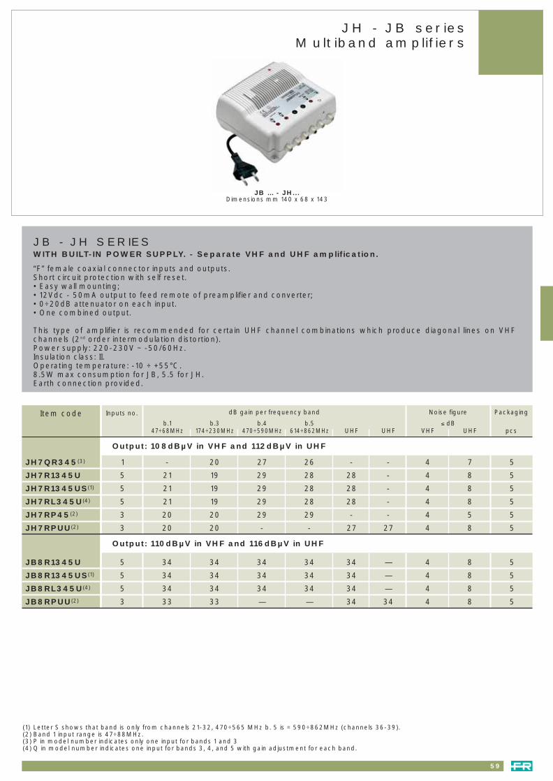
59
JH - JB seriesMultiband amplifiers
Inputs no.Item code
JB … - JH...Dimensions mm 140 x 68 x 143
dB gain per frequency band
b.1 b.3 b.4 b.547÷68MHz 174÷230MHz 470÷590MHz 614÷862MHz UHF UHF
Noise figure
≤ dBVHF UHF
Packaging
pcs
JH7QR345(3)
JH7R1345U
JH7R1345US(1)
JH7RL345U(4)
JH7RP45(2)
JH7RPUU(2)
Output: 108dBµV in VHF and 112dBµV in UHF
Output: 110dBµV in VHF and 116dBµV in UHF
5 34 34 34 34 34 — 4 8 5
5 34 34 34 34 34 — 4 8 5
5 34 34 34 34 34 — 4 8 5
3 33 33 — — 34 34 4 8 5
JB8R1345U
JB8R1345US(1)
JB8RL345U(4)
JB8RPUU(2)
1 - 20 27 26 - - 4 7 5
5 21 19 29 28 28 - 4 8 5
5 21 19 29 28 28 - 4 8 5
5 21 19 29 28 28 - 4 8 5
3 20 20 29 29 - - 4 5 5
3 20 20 - - 27 27 4 8 5
(1) Letter S shows that band is only from channels 21-32, 470÷565 MHz b. 5 is = 590÷862MHz (channels 36-39).(2) Band 1 input range is 47÷88MHz.(3) P in model number indicates only one input for bands 1 and 3(4) Q in model number indicates one input for bands 3, 4, and 5 with gain adjustment for each band.
JB - JH SERIESWITH BUILT-IN POWER SUPPLY. - Separate VHF and UHF amplification.
“F” female coaxial connector inputs and outputs.Short circuit protection with self reset.• Easy wall mounting; • 12Vdc - 50mA output to feed remote of preamplifier and converter; • 0÷20dB attenuator on each input.• One combined output.
This type of amplifier is recommended for certain UHF channel combinations which produce diagonal lines on VHFchannels (2nd order intermodulation distortion). Power supply: 220-230V ~ -50/60Hz.Insulation class: II.Operating temperature: -10 ÷ +55°C.8.5W max consumption for JB, 5.5 for JH.Earth connection provided.
041_064 headends 23-09-2004 16:55 Pagina 59

60
MBX SERIESMultiband amplifier to amplify and mix the signals from several sources. Die-cast housing, fully shielded with F connectors. SeparateVHF and UHF band amplification for 119dBuV version, broadband amplification for 124dBuV version. High gain and high output levelallow the use of these products in medium-large networks. Fully compatible with DTT signals, OFDM modulation.KEY POINTSHigh output level, up to 124dBµV. Test point -30dB available on all the products. All the adjustments are located under the cover toprevent unauthorised access, cover fixed with safety screws. Switch mode power supply, high efficiency and low consumption.USER ADVENTAGESDie-cast nickeled housing, fully shielded. 12V available on every input to feed masthead amplifiers. Gain adjustment 0-20dB onevery input. Spacing kit (ref. MBX0001) available to install the amplifiers over cables or if space is required between the amplifier andthe wall. The spacers give a gap between the amplifier and the wall of 19mm. Packaging 1 piece.
MBX
(1) Ability to extend the Band up to 108 MHz using an internal jumper - (2) MBX0001 spacing kit included in the packaging
MBX0001Accessories Kit composed of n.2 plastic supports & mounting screws. This to be used to install MBX seriesgranting a free empty space between the amplifer and the wall. Packing 10 pieces
GENERAL FEATURES
Gain adjustment 0÷20dB on every inputLinearity ± 2dBIIsolation between input > 20dBRemote power 12V 50mA total, available on any inputTest point - 30dBMains 187÷264Vac 50-60HzPower supply Switch mode, isolation class: IIOperating temperature range -10 ÷ +55 °CImpedance 75ohmConnectors FProtection IP20
Item code MBX7750 MBX5750 MBX5550 MBX7741 MBX5741 MBX5541Number of inputs 5 5 5 4 4 4Gain b. 1 (47 ÷ 68MHz) 40dB(1) 35dB(1) 31dB(1) – – –
b. 3 (174 ÷ 230MHz) 40dB 38dB 31dB – – – b. 4 (470 ÷ 590MHz) 40dB 43dB 30dB – – –b. 5 (606 ÷ 862MHz) 40dB 43dB 30dB – – –b. UHF (470 ÷ 862MHz) 40dB 43dB 30dB 40dB 43dB 30dBb. UHF (470 ÷ 862MHz) – – – 40dB 43dB 30dBb. FM (87,5 ÷ 108MHz) – – – 40dB 35dB 31dBb 1+3 (47 ÷ 68 - 174 ÷ 230MHz) – – – 40dB b.1: 36dB b.3: 38dB 30dB
Max output (-60 dB 3 eq. carr.) dBµV 124 VHF 116 - UHF 119 124 VHF 116 - UHF 119Noise figure dB 11 VHF: 4,5 UHF: 8,5 11 VHF: 4,5 UHF: 7,5Consumption 13,5W 8,5W 8,5W 13,5W 8,5W 8,5WDimension (l x h x d) mm 194x143x64 194x143x53 194x143x64 194x143x53 194x143x53
Item code MBX7750S MBX5750S MBX5550S MBX5752(2) MBX5551(2) MBX5851(2)
Number of inputs 4 4 4 5 5 5Gain b. 1 (47 ÷ 68MHz) 40dB(1) 35dB(1) 31dB(1) – 34dB 34dB
b. 3 (174 ÷ 230MHz) 40dB 38dB 31dB – 34dB 34dBb. 4 (470 ÷ 566MHz) 40dB 43dB 30dB – – –b. 5 (590 ÷ 862MHz) 40dB 43dB 30dB – – –b. UHF (470 ÷ 862MHz) 40dB 43dB 30dB 30dB 32dB 44dBb. UHF (470 ÷ 862MHz) – – – 42dB 32dB 44dBb. UHF (470 ÷ 862MHz) – – – 42dB – –b. FM (87,5 ÷ 108MHz) – – – 35dB 34dB 34dBb 1+3 (47 ÷ 68 - 174 ÷ 230MHz) – – – 36/38dB – –
Max output (-60 dB 3 eq. carr.) dBµV 124 VHF 116 - UHF 119Noise figure dB 11 VHF: 4,5 UHF: 8,5 VHF: 5 UHF: 8,5 Consumption 13,5W 8,5WDimension (l x h x d) mm 194x143x64 194x143x53
MBX SeriesMultiband amplifiers
041_064 headends 23-09-2004 16:55 Pagina 60

61
Digital multiband amplifier
Item code AMP9202U*/AMP9202WNAME Ampli digital 2 U
GAIN BI (47 - 68MHz) 28
FM (87.5 - 108MHz) 28
B III (174 - 230MHz) 38
UHF 1 (470 - 860MHz) 37 / 47dB
UHF 2 (470 - 860MHz) 37 / 47dB
Gain adjustment (dB) 20 dB inter stage
Noise factor at max. gain (dB)
FM /VHF 6
UHF 1 5,5
UHF 2 5,5
Output level (IM3 in accordance with C 90 124/DIN B)
(dBµV) FM /VHF 120/120
UHF 1 118/115
UHF 2 118/115
Consumption 230 V/ 50 Hz (VA) 25
Remote power supply 12V/50mA
Dimensions (L x H x D) 283x125x74mm
Weight 1.1kg
GENERAL FEATURES
Connectors (input/ output) Type F
IMPEDANCE 75Ohms
Standard CE
Level of electrical safety protection Class II
Temperature range –5 /+ 50°C
(dB)
AMP9202U/W
DIGITAL MULTIBAND AMPLIFIERUSED ADVANTAGES
• High 47dB gain in UHF,• Switchable gain 47dB or 37dB, • Inter stage attenuator,• Very low noise figure
(*) AMP9202U: with UK plug
041_064 headends 23-09-2004 16:55 Pagina 61

62
TECHNICAL FEATURES of stock equaliser filters
Number of inputs 1 - 5Number of ouptuts 1 - 4Number of channels 4 - 10Insertion losses 4dB typ.Minimum frequency deviation Between vision carriers 16MHzChannel protection at n +/- 2 18dB typ.Variable attenuation dynamics 18dB typ.Continuous component transmission yesBase plate (mm) Female F inputs
Female F outputsDimensions ( L x H x D) 170 x 105 x 50mmFixing 4 screws
Example of the use of a channel group equaliser filter
Analogue channels Digital channels
Mans Mayet transmitter
DIGITAL FILTER EQUALISERSADVANTAGES• Channel groups : 2 - 4 channels or more with some transmitters • Controlled tilt when adjusting attenuation• Good selectivity (3 cells), • Low insertion losses.• Potentiometer for fine tuning with no deterioration in impedance,N.B. There are ex. filters and filters made to order - See price list
FIL1322001 UHF Band 4 input3 channels1 output
FIL1322011 UHF Band 5 input3 channels1 output
FIL1612001 UHF input6 clusters1 output
FIL1912001 UHF input9 clusters1 output
PAS04363013 inputs: FM – VHF - UHF1 VHF channel5 UHF channels
FIL1412001 UHF input4 clusters1 output
FIL1712001 UHF input7 clusters1 output
FIL1912011 UHF input10 clusters1 output
PAS04373013 inputs: FM-VHF-UHF1 VHF channel6 UHF channels
FIL1512001 UHF input5 clusters1 output
FIL1812001 UHF input8 clusters1 output
PAS04494014 inputs : FM-VHF-UHF1-UHF21 VHF channel5 channels on UHF13 channels on UHF2(all of them in Band 4or Band 5)
b. 4 b. 5 FM VHF UHF
FM VHF UHF1 UHF2
FIL..
FM VHF UHF UHF
UHFUHFUHF
UHFUHFUHF
Digital filter equalisers
041_064 headends 23-09-2004 16:55 Pagina 62
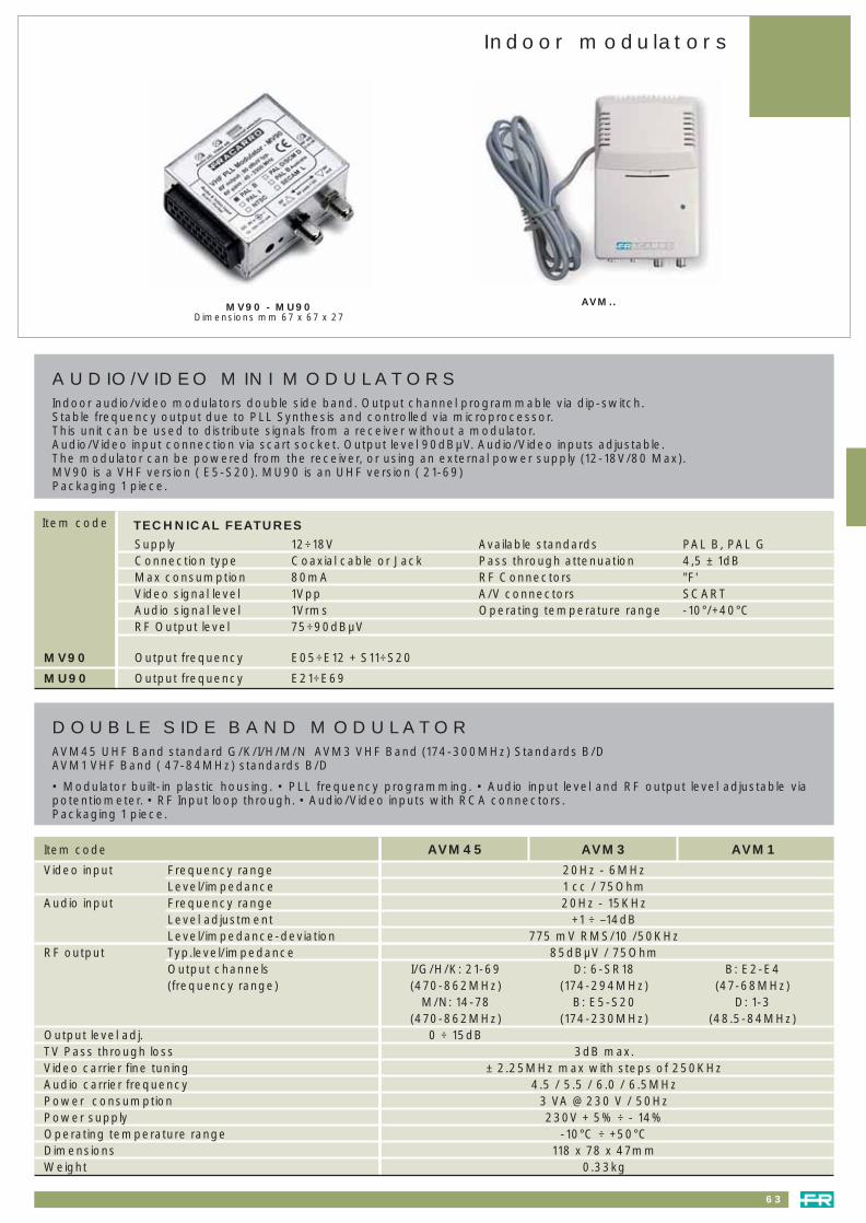
63
Indoor modulators
AUDIO/VIDEO MINI MODULATORSIndoor audio/video modulators double side band. Output channel programmable via dip-switch.Stable frequency output due to PLL Synthesis and controlled via microprocessor.This unit can be used to distribute signals from a receiver without a modulator.Audio/Video input connection via scart socket. Output level 90dBµV. Audio/Video inputs adjustable.The modulator can be powered from the receiver, or using an external power supply (12-18V/80 Max).MV90 is a VHF version ( E5-S20). MU90 is an UHF version ( 21-69)Packaging 1 piece.
MV90
MU90
TECHNICAL FEATURES
12÷18VCoaxial cable or Jack80mA1Vpp1Vrms75÷90dBµV
Output frequency
Output frequency
E05÷E12 + S11÷S20
E21÷E69
SupplyConnection typeMax consumptionVideo signal levelAudio signal levelRF Output level
PAL B, PAL G4,5 ± 1dB"F'SCART-10°/+40°C
Available standardsPass through attenuationRF ConnectorsA/V connectorsOperating temperature range
MV90 - MU90Dimensions mm 67 x 67 x 27
Item code
DOUBLE SIDE BAND MODULATORAVM45 UHF Band standard G/K/I/H/M/N AVM3 VHF Band (174-300MHz) Standards B/DAVM1 VHF Band ( 47-84MHz) standards B/D
• Modulator built-in plastic housing. • PLL frequency programming. • Audio input level and RF output level adjustable viapotentiometer. • RF Input loop through. • Audio/Video inputs with RCA connectors.Packaging 1 piece.
AVM..
Item code AVM45 AVM3 AVM1
Video input Frequency range 20Hz - 6MHzLevel/impedance 1 cc / 75Ohm
Audio input Frequency range 20Hz - 15KHzLevel adjustment +1 ÷ –14dBLevel/impedance-deviation 775 mV RMS/10 /50KHz
RF output Typ.level/impedance 85dBµV / 75OhmOutput channels I/G/H/K: 21-69 D: 6-SR18 B: E2-E4(frequency range) (470-862MHz) (174-294MHz) (47-68MHz)
M/N: 14-78 B: E5-S20 D: 1-3(470-862MHz) (174-230MHz) (48.5-84MHz)
Output level adj. 0 ÷ 15dBTV Pass through loss 3dB max.Video carrier fine tuning ± 2.25MHz max with steps of 250KHzAudio carrier frequency 4.5 / 5.5 / 6.0 / 6.5MHzPower consumption 3 VA @ 230 V / 50HzPower supply 230V + 5% ÷ - 14%Operating temperature range -10°C ÷ +50°CDimensions 118 x 78 x 47mmWeight 0.33kg
041_064 headends 23-09-2004 16:55 Pagina 63

64
Headend amplifiers
AMP9764
TECHNICAL FEATURES
Item code AMP9404B AMP9404A AMP9764
SATELLITE CHANNEL
Frequency band 950 - 2150MHz 950 - 2150MHz 950 - 2150MHz
Gain 14 - 20dB 28dB 40dB
Gain adjustment 0 - 10dB 0 - 15dB 0 - 20dB
Tilt adjustment - 0 - 10dB 0 - 20dB
Output level
(IM3, 2 carriers, equal) 114dBµV 116dBµV 125dBµV
Noise factor 7dB 8dB 10dB
LNB Remote power supply 12 V - 350mA 12 V - 350mA 0/14/18V 0/22Hz (adj.)
TERRESTRIAL LINK
Frequency band 47 - 862MHz 47 - 862MHz 47 - 862MHz
Transmission loss 2dB 2dB 2dB
GENERAL
Impedance 75 Ω 75 Ω 75 Ω
Operating temperature -5 / +50°C -5 / +50°C -10 / +55°C
Dimensions (l x h x d) 193 x 125 x 74mm 193 x 125 x 74mm 194 x 143 x 53mm
Weight 1Kg 1Kg –
Consumption (230 V/50Hz) 8W 10W 11W
Connectors F F F
HEADEND AMPLIFIERSOPERATING PRINCIPLESAmplification of satellite band with terrestrial loop through
ADVANTAGES• Gain adjustment• Tilt adjustment (AMP9404A)• Integral LNB power supply
AMP9404AAMP9404B
041_064 headends 23-09-2004 16:55 Pagina 64

Multiswitches
Compact3D SwitchlineGII Switchline
CascadableSmart XS SwitchlineAmplifiers SwitchlineGII Switchline
Page 6667-68
69-70-7172
73-74
A new range that fits every demand of signal distribution: singlehouses as well as large buildings (MDU’s)
065_074 switchline 23-09-2004 16:56 Pagina 65

66
Compact 3D Switchline
COMPACT SWITCHLINE 3DThe Compact Switchline range 3D is fully compatible with digital satellite and terrestrial signals. The products have been designed to be installed in small to medium sized installations.
PRODUCT ADVANTAGESHigh number of outputs; small in size; active satellite band no through loss (0dB): to guarantee the quality of the satellitesignals with long cable drops; the TV band 5÷862MHz forward and return path are passive; terrestrial 12V power supplyto feed pre amplifier on terrestrial input: wall fixings provided; versatile installation, products can be fitted sideways,horizontally and vertically. Packaging 1pc
Item code SWI5512A SWI5516A(1)SWI5508ASWI5506A
SWI5912A
4Sat +1Terr 4Sat +1Terr 4Sat +1Terr 4Sat +1Terr
6 8 12 16
+2dB to +4dB Tilted +2dB to +4dB Tilted -1dB to +3dB Tilted 0dB
90dBµv 90dBµv 90dBµv 88dBµv
-16dB -17dB -20dB -20dB
>28dB >28dB >28dB >28dB
265x125x65 305x125x65 385x125x65 445x125x65
300mA/14V 300mA/14V 300mA/14V 300mA/14V
12V 100mA 12V 100mA 12V 100mA 12V 100mA
N. of inputs
N. of outputs
Satellite through loss/gain
Maximum Sat output level
(-35 dB, 2 carriers)
Terrestrial loss
Isolation between inputs
Dimension mm
SAT inputs remote power
TV inputs remote power
SWI5912A SWI5916A(1)SWI5908A
8Sat +1Terr 8Sat +1Terr 8Sat +1Terr
8 12 16
+3dB +2dB 0dB
90dBµv 90dBµv 88dBµv
-16dB -18dB -20dB
>28dB >28dB >28dB
305x125x65 385x125x65 445x125x65
600mA/14V 600mA/14V 600mA/14V
12V 100mA 12V 100mA 12V 100mA
N. of inputs
N. of outputs
Taps satellite gain
Maximum sat output level
(-35 dB, 2 carriers)
Terrestrial gain
Isolation between inputs
Dimension mm
SAT inputs remote power
TV inputs remote power
Item code
(1) These are preliminary specifications
065_074 switchline 23-09-2004 16:56 Pagina 66
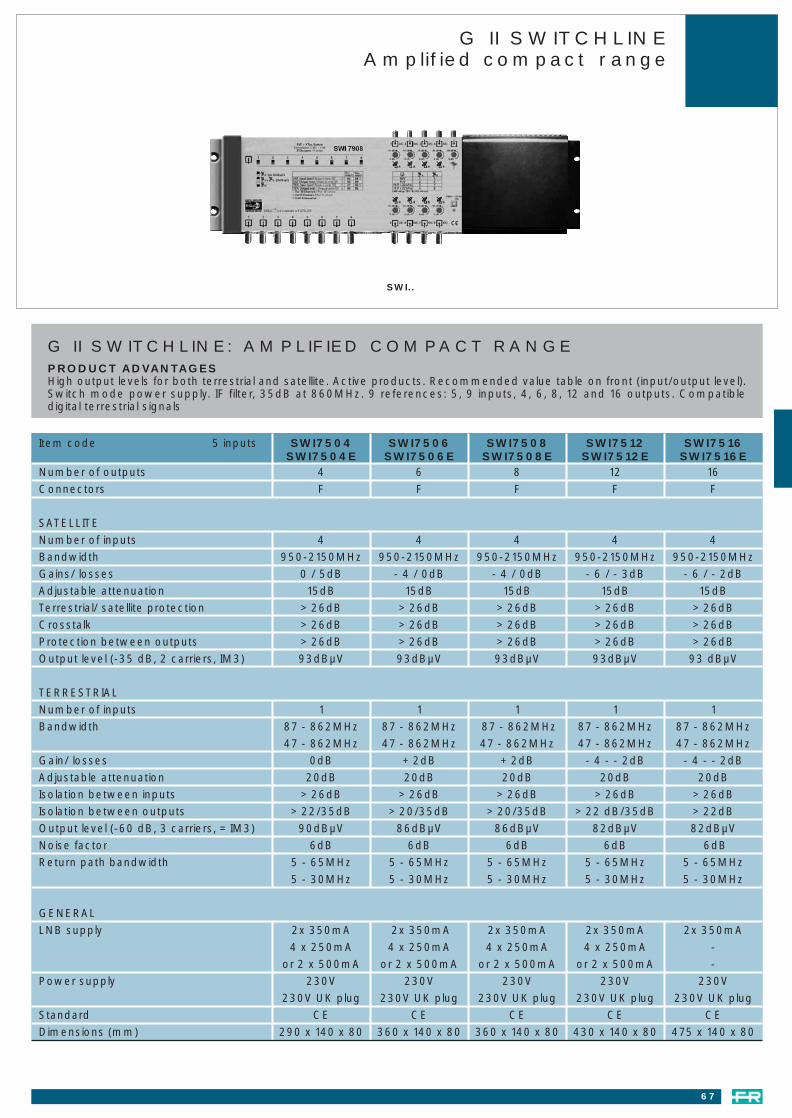
Number of outputs 4 6 8 12 16
Connectors F F F F F
SATELLITE
Number of inputs 4 4 4 4 4
Bandwidth 950-2150MHz 950-2150MHz 950-2150MHz 950-2150MHz 950-2150MHz
Gains/ losses 0 / 5dB - 4 / 0dB - 4 / 0dB - 6 / - 3dB - 6 / - 2dB
Adjustable attenuation 15dB 15dB 15dB 15dB 15dB
Terrestrial/ satellite protection > 26dB > 26dB > 26dB > 26dB > 26dB
Crosstalk > 26dB > 26dB > 26dB > 26dB > 26dB
Protection between outputs > 26dB > 26dB > 26dB > 26dB > 26dB
Output level (-35 dB, 2 carriers, IM3) 93dBµV 93dBµV 93dBµV 93dBµV 93 dBµV
TERRESTRIAL
Number of inputs 1 1 1 1 1
Bandwidth 87 - 862MHz 87 - 862MHz 87 - 862MHz 87 - 862MHz 87 - 862MHz
47 - 862MHz 47 - 862MHz 47 - 862MHz 47 - 862MHz 47 - 862MHz
Gain/ losses 0dB + 2dB + 2dB - 4 - - 2dB - 4 - - 2dB
Adjustable attenuation 20dB 20dB 20dB 20dB 20dB
Isolation between inputs > 26dB > 26dB > 26dB > 26dB > 26dB
Isolation between outputs > 22/35dB > 20/35dB > 20/35dB > 22 dB/35dB > 22dB
Output level (-60 dB, 3 carriers, = IM3) 90dBµV 86dBµV 86dBµV 82dBµV 82dBµV
Noise factor 6dB 6dB 6dB 6dB 6dB
Return path bandwidth 5 - 65MHz 5 - 65MHz 5 - 65MHz 5 - 65MHz 5 - 65MHz
5 - 30MHz 5 - 30MHz 5 - 30MHz 5 - 30MHz 5 - 30MHz
GENERAL
LNB supply 2x 350mA 2x 350mA 2x 350mA 2x 350mA 2x 350mA
4 x 250mA 4 x 250mA 4 x 250mA 4 x 250mA -
or 2 x 500mA or 2 x 500mA or 2 x 500mA or 2 x 500mA -
Power supply 230V 230V 230V 230V 230V
230V UK plug 230V UK plug 230V UK plug 230V UK plug 230V UK plug
Standard CE CE CE CE CE
Dimensions (mm) 290 x 140 x 80 360 x 140 x 80 360 x 140 x 80 430 x 140 x 80 475 x 140 x 80
67
G II SWITCHLINEAmplified compact range
SWI..
G II SWITCHLINE: AMPLIFIED COMPACT RANGEPRODUCT ADVANTAGESHigh output levels for both terrestrial and satellite. Active products. Recommended value table on front (input/output level).Switch mode power supply. IF filter, 35dB at 860MHz. 9 references: 5, 9 inputs, 4, 6, 8, 12 and 16 outputs. Compatibledigital terrestrial signals
Item code 5 inputs SWI7504 SWI7506 SWI7508 SWI7512 SWI7516SWI7504E SWI7506E SWI7508E SWI7512E SWI7516E
065_074 switchline 23-09-2004 16:56 Pagina 67

68
G II SWITCHLINEAmplified compact range
Number of outputs 4 6 8 12
Connectors F F F F
SATELLITE
Number of inputs 8 8 8 8
Bandwidth 950 - 2150MHz 950 - 2150MHz 950 - 2150MHz 950 - 2150MHz
Gain/ losses 0 / +3dB - 4 / + 0dB - 5 / 1dB - 6 / -3dB
Adjustable attenuation 15dB 15dB 15dB 15dB
Terrestrial/ satellite protection > 26dB > 26dB > 26dB > 26dB
Crosstalk > 26dB > 26dB > 26dB > 26dB
Protection between outputs > 26dB > 26dB > 26dB > 26dB
Output level (-35 dB, 2 carriers, IM3) 95dBµV 95dBµV 95dBµV 93dBµV
Logical 9 inputs DiSEqC con position A
TERRESTRIAL
Number of inputs 1 1 1 1
Bandwidth 87 - 862MHz 87 - 862MHz 87 - 862MHz 87 - 862MHz
47 - 862MHz 47 - 862MHz 47 - 862MHz 47 - 862MHz
Gain/ losses + 4 - + 6dB + 5 - + 7dB + 5 - + 7dB + 4dB
Adjustable attenuation 20dB 20dB 20dB 20dB
Isolation between inputs > 26dB > 26dB > 26dB > 26dB
Isolation between outputs > 22/35dB > 20/35dB > 20/35dB > 22 dB/35dB
Output level (-60 dB, 3 carriers, = IM3) 88dBµV 86dBµV 86dBµV 84dBµV
Noise factor 6dB 6dB 6dB 6dB
Return path bandwidth 5 - 65MHz 5 - 65MHz 5 - 65MHz 5 - 65MHz
5 - 30MHz 5 - 30MHz 5 - 30MHz 5 - 30MHz
GENERAL
LNB supply 2x 350mA 2x 350mA 2x 350mA 2x 350mA
4 x 250mA 4 x 250mA 4 x 250mA 4 x 250mA
or 2 x 500mA or 2 x 500mA or 2 x 500mA or 2 x 500mA
Power supply 230V 230V 230V 230V
— — — 230V
Standard CE CE CE CE
Dimensions (mm) 290 x 140 x 80 360 x 140 x 80 360 x 140 x 80 430 x 140 x 80
SWI7908
G II SWITCHLINE: AMPLIFIED COMPACT RANGEPRODUCT ADVANTAGESHigh output levels for both terrestrial and satellite. Active products. Recommended value table on front (input/outputlevel). Switch mode power supply. IF filter, 35 dB at 860 MHz. 9 references: 5, 9 inputs, 4, 6, 8, 12 and 16 outputs.Compatible with terrestrial digital.
Item code 9 inputs SWI7904 SWI7906 SWI7908 SWI7912SWI7904F SWI7908F SWI7912F
065_074 switchline 23-09-2004 16:56 Pagina 68

SMART SWITCHLINE XS4, XS5 and XS9Smart Switchline XS is a new range of multi switches developed for small and medium sized cascadable systems. Theyare designed to carry switched IF and TV signals to many outlets from a single headend. Smart Switchline XS combineshigh quality in a compact size for easy installation in small spaces.
SMART SWITCHLINE XS4KEY POINTSThe outputs are along one side to make installation neat and easy and wall fixings are provided. The cost effectiveconfiguration offers different levels of attenuation -17dB, -8dB and 0dB. They can be used with long cable drop lengthswithout compromising signal quality. The LNB supply can be fed, via the switches, from the receiver and the inputs onthe front are colour coded for easy installation. Packaging 1pc
69
N. of Inputs 4 4 4
N. of Outputs 6 6 6
Taps Satellite Gain -17dB -8dB 0dB
Maximun Sat output level
(-35dB/2 carriers) - 105dBµV 105dBµV
Satellite Insertion loss -2dB -2dB -2dB
Protection betwen Inputs >28dB >28dB >28dB
Dimension mm 119x70x20 119x70x20 119x70x20
Consumption without LNB 15mA 35mA 35mA
SWI4406-17(1) SWI4406-08(1) SWI4406-00(1) NItem code
N. of Inputs 4 4 4
N. of Outputs 4 4 4
Taps Satellite Gain -17dB -8dB 0dB
Maximun Sat output level
(-35dB/2 carriers) - 105dBµV 105dBµV
Satellite Insertion loss -2dB -2dB -2dB
Protection betwen Inputs >28dB >28dB >28dB
Dimension mm 90x70x20 90x70x20 90x70x20
Consumption without LNB 15mA 35mA 35mA
SWI4404-17(1) SWI4404-08(1) SWI4404-00(1) NItem code
Smart Switchline XS 46 outputs
Smart Switchline XS 44 outputs
newnew
(1) These are preliminary specifications
Smart XS SwitchlineCascadable range
065_074 switchline 23-09-2004 16:56 Pagina 69

70
Smart XS SwitchlineCascadable range
N. of inputs 4 sat + 1 ter 4 sat + 1 ter 4 sat + 1 ter 4 sat + 1 ter 4 sat + 1 ter 4 sat + 1 ter
N. of outputs 4 4 4 4 6 6
Taps satellite gain -20dB to -16dB Tilted -8 -2dB +1dB Tilted -1dB to +2dB Tilted -21dB to -16dB Tilted -8
Satellite Insertion loss -2dB -2dB -2dB — -2,5dB -2,5dB
Max Sat output level
(-35dB/2 carriers) — 110dBµV 105dBµV 105dBµV — 110dBµV
TV Derivation -19dB -15dB -15dB -12dB -19dB -15dB
TV Transition -2,5dB -3dB -3,5dB — -4dB -4,5dB
Protection between inputs >28dB >28dB >28dB >28dB >28dB >28dB
Dimensions mm 120x118x30mm 120x118x30mm 120x118x30mm 120x118x30mm 160x108x30mm 160x108x30mm
Consumption without LNB 15mA 40mA 35mA 35mA 15mA 40mA
SWI3506A10SWI3506PSWI3504TSWI3504ASWI3504A10SWI3504PItem code
N. of inputs 4 sat + 1 ter 4 sat + 1 ter 4 sat + 1 ter 4 sat + 1 ter 4 sat + 1 ter 4 sat + 1 ter
N. of outputs 6 6 8 8 8 8
Taps satellite gain -3dB to +1dB Tilted -2dB to +2dB Tilted -21dB to -16dB Tilted -8 -2dB to +1dB Tilted -2dB to +1dB Tilted
Satellite Insertion loss -2,5dB — -3,5dB -3,5dB -3,5dB —
Max Sat output level
(-35dB/2 carriers) 105dBµV 105dBµV — 110dBµV 105dBµV 105dBµV
TV Derivation -15dB -13dB -25dB -22dB -22dB -14dB
TV Transition -5dB — -1dB -3dB -3dB —
Protection between inputs >28dB >28dB >28dB >28dB >28dB >28dB
Dimensions mm 160x118x30mm 160x118x30mm 200x118x30mm 200x118x30mm 160x108x30mm 200x108x30mm
Consumption without LNB 35mA 35mA 15mA 40mA 35mA 35mA
SWI3508TSWI3508ASWI3508A10SWI3508PSWI3506TSWI3506AItem code
SWM1305A Kit to combine XS 5 switch and MiniDiSEqC
SWITCHLINE XS 5 16 POLARITESTo distribute up to 16 satellite polarities by combining the XS 5 input switchline range with the mini DiSEqC switch.Use the kit SWM1305A to fix the switches to the wall.
SWI1201B
SWI1301B
SWI1401B
SWI1501B
Isolationbetwen inputs
dB
Powerconsump.by rx mA
Switchcontrol
Insertion loss (dB)
SAT TV
Number ofoutputs
Number of outputs
SAT TV
2 (1 with TV Mixed) 0
2 1
4 (1 with TV Mixed) 0
4 1
1
1
1
1
-2
-2
-3
-3
1,5
1,5
1,5
1,5
DiSEqC 2.0
DiSEqC 2.0
DiSEqC 2.0
DiSEqC 2.0
25
25
25
25
>28
>28
>28
>28
Smart Switchline XS 5
SMART SWITCHLINE XS5KEY POINTS: The outputs are along one side to make installation neat and easy and wall fixings are provided. The costeffective configuration offers different levels of attenuation -16dB passive, active -8dB, active 0dB and terminal 0dB. Theycan be used with long cable drop lengths without compromising signal quality. TV Band 5-862MHz has a passive forwardand return path. The inputs on the front are colour coded for easy installation. When combined with the MiniDiSEqCswitches using a mounting tool kit it is possible to distribute 16 polarities + TV. Packaging 1pc
16 polarites
065_074 switchline 23-09-2004 16:56 Pagina 70

SMART SWITCHLINE XS9KEY POINTSThe outputs are along one side to make installation easy and neat. Within the packaging there is a plastic support to fixthe switch either vertically or horizontally on the wall. The cost effective configuration offers different levels of attenuationpassive -16dB, active 0dB and terminal 0dB. They can be used with long cable drop lengths without compromising signalquality. TV Band 5-862MHz has a passive forward and return path. On each output there is a dip-switch for DiSEqCinversion. Packaging 1pc
SWI3904A SWI3906A SWI3908A
71
N. of Inputs 8sat + 1ter. 8sat + 1ter. 8sat + 1ter.
N. of Outputs 4 4 4
Taps Satellite Gain -20dB to -16dB Tilted 0dB to +2dB Tilted +2dB to +4dB Tilted
Satellite Insertion loss -3dB -3dB -
Maximun Sat output level (-35dB/2 carriers) - 105dBµV 105dBµV
TV Derivation -18dB -15dB -10dB
TV Transition -4dB -4dB -
Protection betwen Inputs >28dB >28dB >28dB
Dimension mm 125x125x52 125x125x52 125x125x52
Consumption without LNB 35mA 50mA 50mA
SWI3904P SWI3904A SWI3904TItem code
N. of Inputs 8sat + 1ter. 8sat + 1ter. 8sat + 1ter.
N. of Outputs 8 8 8
Taps Satellite Gain -21dB to -16dB Tilted -2dB to 0dB Tilted +1dB to +3dB Tilted
Satellite Insertion loss -4dB -4dB -
Maximun Sat output level (-35dB/2 carriers) - 105dBµV 105dBµV
TV Derivation -25dB -22dB -15dB
TV Transition -2dB -3dB -
Protection betwen Inputs >28dB >28dB >28dB
Dimension mm 210x125x52 210x125x52 210x125x52
Consumption without LNB 35mA 50mA 50mA
SWI3908P SWI3908A SWI3908TItem code
N. of Inputs 8sat + 1ter. 8sat + 1ter. 8sat + 1ter.
N. of Outputs 6 6 6
Taps Satellite Gain -20dB to -17dB Tilted -3dB to 0dB Tilted 0dB to +3dB Tilted
Satellite Insertion loss -3dB -3dB -
Maximun Sat output level (-35dB/2 carriers) - 105dBµV 105dBµV
TV Derivation -19dB -16dB -13dB
TV Transition -3dB -4dB -
Protection betwen Inputs >28dB >28dB >28dB
Dimension mm 170x125x52 170x125x52 170x125x52
Consumption without LNB 35mA 50mA 50mA
SWI3906P SWI3906A SWI3906TItem code
Smart XS SwitchlineCascadable range
065_074 switchline 23-09-2004 16:56 Pagina 71

Amplifiers Switchline
AMP9254 AMP9254A
HEADEND AMPLIFIERS FOR CASCADABLE SYSTEMSRange of SAT amplifiers with TV input dedicated to the Smart Switch Line XS range. The gain is adjustable on all of the SAT inputs. Versions available with 5 and 9 inputs.
PRODUCTS ADVANTAGESThe product uses a “Switch Mode” power supply that guarantees high reliability for the product; AMP9254 and AMP9294have a fixed slope to ensure the correct signal level with long cable lengths. There is gain control on every input; on theAMP9254A there is slope adjustment on every output. The TV band 5÷862MHz is passive for the forward and return path.Packaging 1pc
Item code
AMP9254
AMP9254A
AMP9294
N. ofinputs
Satellite Gain
(dB)
Terrestrial loss(dB)
Gain adj.(dB)
Slopeadj.(dB)
Isolationbetween
inputs (dB)
Powersupply
Dimensions
mm
Output*level max.(dBµV)
LNB powersupply
4 SAT+ TERR
19 (950MHz)25 (2150MHz)
TILT FISSO–1 15 – >28
230Vac±10%
16 235x125x65 112 400mA@14V
4 SAT+ TERR
32 –1 15 0-12 >28230Vac
±10%19 235x125x65 116 400mA@14V
8 SAT+ TERR
19 (950MHz)25 (2150MHz)
TILT FISSO–1 15 – >28
230Vac±10%
20 235x125x65 112 600mA@14V
POWER SUPPLY WITH D.C. INSERTER
SPS1750
The D.C. power inserter. It provides a 15Vcc 500mA output voltage and is supplied with 220-230V ~ 50MHz.The D.C. inserter works from 40 to 2150MHz with a 1 dB insertion loss. With female F connectors.Insulation class: II. Operating temperature: -10°C 55°C. Packaging 1pc.
AMP9294
Powerconsumption
W
72
* (-32dB/2 carriers)
065_074 switchline 23-09-2004 16:56 Pagina 72

G II SWITCHLINECascadable range
Item code AMP9444A AMP8331A AMP9244A AMP9853 SWI6504 SWI6506 SWI6508 SWI6512 SWI6516AMP9444 AMP8331 AMP9284A AMP9893 SWI6904 SWI6906 SWI6908 SWI6912
SATELLITENumber of inputs 4 1 4/8 4/8 4/8 4/8 4/8 4/8 4Number of outputs 4 1 4/8 4/8 4 6 8 12 16Band width (MHz) 950 -2400 5 -2400 950 -2400 950 -2150 950 -2150 950 -2150 950 -2150 950 -2150 950-2150Gain (dB) 30 – 30 17 – – – – –Loss (dB) – – – – 0 - 5 / 0-4 -4 - 1/-4 - 0 -4 - 0/5 - 0 -6 - 3/ -6 - 0 -6 to -5
Attenuation adjustment (dB) 15 – 15 15 15 15 15 15 15Pre-emphasis adjustment (dB) 10 – – 15 – – – – –Fixed tilt – – 6 dB – – – – – –Ouput level (dBµV, -35dB. 2 carriers, IM3) 118 – 114 115 93/95 93/95 93/95 93/95 93Noise factor (dB) >10 – 10 10 7 7 7 7 7Filter selectivity at 830 MHz >35 – >35 >35 26 26 26 26 >26Current available for LNB (mA) 600 – 400/600 – – – – – –LNB power supply (V) 14-18 – 18V – – – – – –TERRESTRIALNumber of inputs – – – 1 1 1 1 1 1Number of outputs – – – 1 1 1 1 1 1Band width (MHz) – 5 - 2400 – 87- 862 87-862 8762 87-862 87-862 47-862Gain (dB) – – – 15 0/4-7 2/5-7 2/5-7 -4/2-4 -4Attenuation adjustment (dB) – – – 15 -20 20 20 20 20Pre-emphasis adjustment (dB) – – – 15 – – – – –Output level (dBµV, -60dB, 3 carriers, IM3) – – – 108 -90/88 86/86 86/86 82/84 82Noise factor (dB) – – – 10 6 6 6 6 7Return path (MHz) – – – 5-65 -5 -65 5-65 5-65 5-65 5-30Transmission loss (dB) – – – 2 6 10 10 14 18GENERALConnectors F F F F F F F F FImpedance (ohms) 75 75 75 75 75 75 75 75 75Power supply (V) 207-264 207-264 207-264 – – – – – –Remote power supply (V) – – – 15-18 15-18 15-18 15-18 15-18 15-18Current consumption 30 VA – 60 VA 500/750 mA 300/2x200 mA 350/2x250mA 350/2x250mA 400/2x250mA 500mA
Current transmission per SAT channel (A) 1,5 – 1,5 1,5 – – – – –Line power supply 3A-18V 2A – – – – – –Operating temperature +5°- + 50°C +5°- + 50°C +5°- + 50°C +5°- + 50°C +5°- + 50°C +5°- + 50°C +5°- + 50°C +5°- + 50°C +5° - +50°CStandard CE CE CE CE CE CE CE CE CEDimensions (mm) 277x132x75 188x110x75 277x132x75 183x132x43 205x140x52 275x140x52 275x140x52 345x140x52 410x140x52
308x132x75 290x132x43 275x140x52 345x140x52 345x140x52 345x140x52
AMP8331A Power supply
3A/18V
AMP92X4A - AMP9444AAMP92X4U - AMP9444
Head amplifier4 - 8 high level satellite
amplifiers in the same product
AMP9853 - AMP9893 Line amplifiers
5 - 9 independent amplifiers in thesame product
SWI6..Active switches
4, 6, 8, 12 and 16 high leveloutputs for flexible installations
73
065_074 switchline 23-09-2004 16:56 Pagina 73
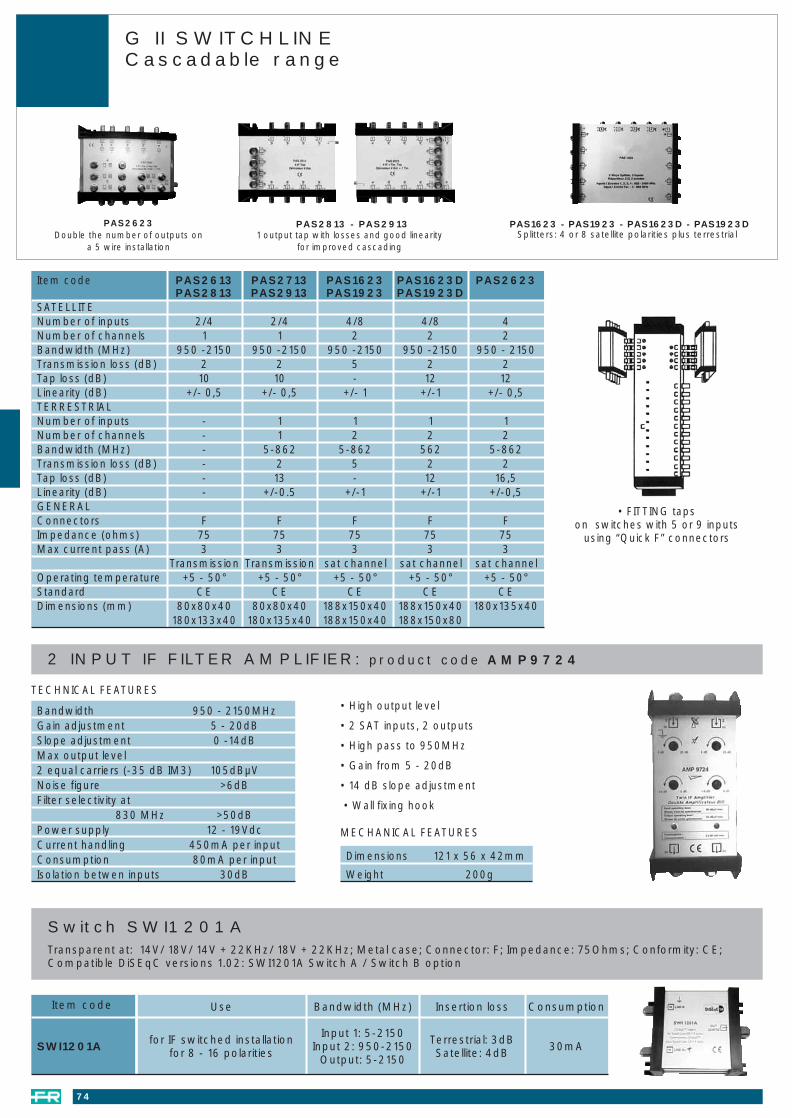
Item code PAS2613 PAS2713 PAS1623 PAS1623D PAS2623PAS2813 PAS2913 PAS1923 PAS1923D
SATELLITENumber of inputs 2/4 2/4 4/8 4/8 4Number of channels 1 1 2 2 2Bandwidth (MHz) 950 -2150 950 -2150 950 -2150 950 -2150 950 - 2150Transmission loss (dB) 2 2 5 2 2Tap loss (dB) 10 10 - 12 12Linearity (dB) +/- 0,5 +/- 0,5 +/- 1 +/-1 +/- 0,5TERRESTRIALNumber of inputs - 1 1 1 1Number of channels - 1 2 2 2Bandwidth (MHz) - 5-862 5-862 562 5-862Transmission loss (dB) - 2 5 2 2Tap loss (dB) - 13 - 12 16,5Linearity (dB) - +/-0.5 +/-1 +/-1 +/-0,5GENERALConnectors F F F F FImpedance (ohms) 75 75 75 75 75Max current pass (A) 3 3 3 3 3
Transmission Transmission sat channel sat channel sat channelOperating temperature +5 - 50° +5 - 50° +5 - 50° +5 - 50° +5 - 50°Standard CE CE CE CE CEDimensions (mm) 80x80x40 80x80x40 188x150x40 188x150x40 180x135x40
180x133x40 180x135x40 188x150x40 188x150x80
• FITTING tapson switches with 5 or 9 inputs
using “Quick F” connectors
MECHANICAL FEATURES
• High output level
• 2 SAT inputs, 2 outputs
• High pass to 950MHz
• Gain from 5 - 20dB
• 14 dB slope adjustment
• Wall fixing hook
TECHNICAL FEATURES
Bandwidth 950 - 2150MHzGain adjustment 5 - 20dBSlope adjustment 0 -14dBMax output level2 equal carriers (-35 dB IM3) 105dBµVNoise figure >6dBFilter selectivity at
830 MHz >50dBPower supply 12 - 19VdcCurrent handling 450mA per inputConsumption 80mA per inputIsolation betwen inputs 30dB
Dimensions 121 x 56 x 42mm
Weight 200g
2 INPUT IF FILTER AMPLIFIER: product code AMP9724
G II SWITCHLINECascadable range
PAS2813 - PAS29131 output tap with losses and good linearity
for improved cascading
PAS2623Double the number of outputs on
a 5 wire installation
PAS1623 - PAS1923 - PAS1623D - PAS1923DSplitters: 4 or 8 satellite polarities plus terrestrial
Switch SWI1201ATransparent at: 14V/ 18V/ 14V + 22KHz/ 18V + 22KHz; Metal case; Connector: F; Impedance: 75Ohms; Conformity: CE; Compatible DiSEqC versions 1.02: SWI1201A Switch A / Switch B option
Use Bandwidth (MHz) Insertion loss Consumption
SWI1201A
Item code
for IF switched installationfor 8 - 16 polarities
Input 1: 5-2150Input 2: 950-2150
Output: 5-2150
Terrestrial: 3dBSatellite: 4dB
30mA
74
065_074 switchline 23-09-2004 16:56 Pagina 74

Fibre optic distributionLine amplifiers
Solutions for fibre optic distribution Fibre optic equipment for CATV applicationsK seriesAccessoriesCase history
Line amplifiersRF amplifiersCATV amplifiersCATV accessoriesC4 amplifiers
Page 76777879
8081-82-83
84-8586
Fracarro have an extensive experience in the development, andimplementation, of Fibre Optic products. The Bernabeu stadiumis a good example of a well known stadium where Fracarro havesuccessfully implemented these products
075_086 fibre optics 23-09-2004 16:56 Pagina 75
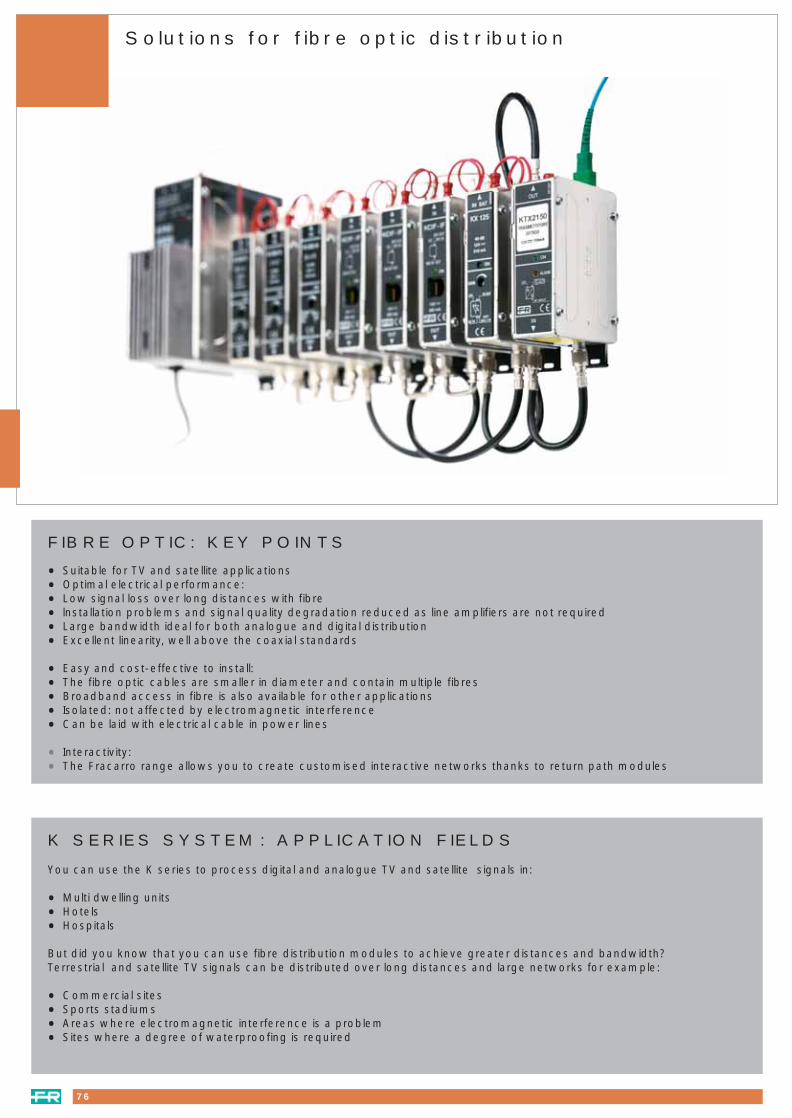
76
FIBRE OPTIC: KEY POINTS
• Suitable for TV and satellite applications
• Optimal electrical performance:
• Low signal loss over long distances with fibre
• lnstallation problems and signal quality degradation reduced as line amplifiers are not required
• Large bandwidth ideal for both analogue and digital distribution
• Excellent linearity, well above the coaxial standards
• Easy and cost-effective to install:
• The fibre optic cables are smaller in diameter and contain multiple fibres
• Broadband access in fibre is also available for other applications
• Isolated: not affected by electromagnetic interference
• Can be laid with electrical cable in power lines
• Interactivity:
• The Fracarro range allows you to create customised interactive networks thanks to return path modules
Solutions for fibre optic distribution
K SERIES SYSTEM: APPLICATION FIELDS
You can use the K series to process digital and analogue TV and satellite signals in:
• Multi dwelling units
• Hotels
• Hospitals
But did you know that you can use fibre distribution modules to achieve greater distances and bandwidth?Terrestrial and satellite TV signals can be distributed over long distances and large networks for example:
• Commercial sites
• Sports stadiums
• Areas where electromagnetic interference is a problem
• Sites where a degree of waterproofing is required
075_086 fibre optics 23-09-2004 16:57 Pagina 76
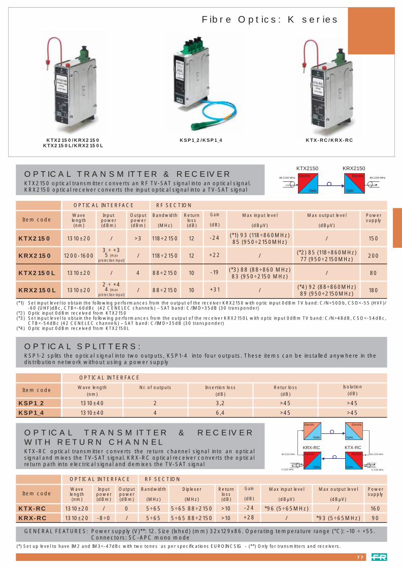
OPTICAL TRANSMITTER & RECEIVERKTX2150 optical transmitter converts an RF TV-SAT signal into an optical signal.KRX2150 optical receiver converts the input optical signal into a TV-SAT signal
77
Fibre Optics: K series
KTX2150/KRX2150KTX2150L/KRX2150L
KSP1_2/KSP1_4
Item code
KTX2150
KRX2150
KTX2150L
KRX2150L
Max output level
(dBµV)
Powersupply
Wavelength(nm)
1310±20
1200-1600
Inputpower(dBm)
Outputpower(dBm)
/ >3
3 ÷ +35 (max
protection input)/
Bandwidth
(MHz)
118÷2150
118÷2150
Returnloss(dB)
12
12
Gain
(dB)
-24 / 150
+22 (*2) 85 (118÷860MHz)77 (950÷2150MHz)
200
Max input level
(dBµV)
(*1) 93 (118÷860MHz)85 (950÷2150MHz)
/
1310±20 / 4 88÷2150 10 -19 / 80(*3) 88 (88÷860 MHz)83 (950÷2150 MHz)
1310±202 ÷ +44 (max
protection input)/ 88÷2150 10 +31 (*4) 92 (88÷860MHz)
89 (950÷2150MHz)180/
OPTICAL INTERFACE RF SECTION
Electric
Optic
Electric
Optic
KTX2150 KRX2150
88-2150 MHz88-2150 MHz
KTX-RC/KRX-RC
(*1) Set input level to obtain the following performances from the output of the receiver KRX2150 with optic input 0dBm TV band: C/N>50Db, CSO<-55 (HVF)/-60 (UHF)dBc, CTB<-60dBc (42 CENELEC channels) – SAT band: C/IMD>35dB (30 transponder)
(*2) Optic input 0dBm received from KTX2150(*3) Set input level to obtain the following performances from the output of the receiver KRX2150L with optic input 0dBm TV band: C/N>48dB, CSO<-54dBc,
CTB<-54dBc (42 CENELEC channels) – SAT band: C/IMD>35dB (30 transponder)(*4) Optic input 0dBm received from KTX2150L
Item code
KSP1_2
KSP1_4
OPTICAL INTERFACE
Wave length(nm)
Nr. of outputs Insertion loss(dB)
Retur loss(dB)
Isolation(dB)
1310±40 2 3,2 >45 >45
1310±40 4 6,4 >45 >45
OPTICAL SPLITTERS:KSP1-2 splits the optical signal into two outputs, KSP1-4 into four outputs. These items can be installed anywhere in thedistribution network without using a power supply
OPTICAL TRANSMITTER & RECEIVERWITH RETURN CHANNELKTX-RC optical transmitter converts the return channel signal into an opticalsignal and mixes the TV-SAT signal. KRX-RC optical receiver converts the opticalreturn path into electrical signal and demixes the TV-SAT signal
Item code
KTX-RC
KRX-RC
Max output level
(dBµV)
Powersupply
Wavelength(nm)
1310±20
1310±20
Inputpower(dBm)
/
-8÷0
Outputpower(dBm)
0
/
Bandwidth
(MHz)
5÷65
5÷65
Diplexer
(MHz)
5÷65 88÷2150
5÷65 88÷2150
Returnloss(dB)
>10
>10
Gain
(dB)
-24 / 160
+28 *93 (5÷65MHz) 90
Max input level
(dBµV)
*96 (5÷65MHz)
/
OPTICAL INTERFACE RF SECTION
Electric
Optic
Electric
Optic
Electric
Optic
Electric
Optic
KRX-RC KTX-RC88-2150 MHz
5-2150 MHz
88-2150 MHz
5-2150 MHz
GENERAL FEATURES: Power supply (V)**: 12. Size (lxhxd) (mm) 32x129x86. Operating temperature range (°C): –10 ÷ +55.Connectors: SC-APC mono mode
(*) Set up level to have IM2 and IM3<-47dBc with two tones as per specifications EUROINCSIG - (**) Only for transmitters and receivers.
075_086 fibre optics 23-09-2004 16:57 Pagina 77

78
Fibre Optic: accessories
OPC4OMA - OPC8OMA
OPC4OM - OPC8OM
OPC4IM - OPC8IM
BFO - SC - APC
BR.. - ..
OPB.. OPO12P
OPB24IR
For indoor applications-not to be used in extreme conditions
Cable with 4 singlemode fibres
Cable with 8 singlemode fibres
For indoor and outdoor application - can be used in extreme conditions and laid directly underground.
Cable with 4 singlemode fibres
Cable with 8 singlemode fibres
For indoor and outdoor application - can be used in extreme conditions and laid directly underground.Complete with metal armour for rodent proofing.
Cable with 4 singlemode fibres
Cable with 8 singlemode fibres
OPC4IM
OPC8IM
OPC4OM
OPC8OM
OPC4OMA
OPC8OMA
Item code
FIBRE OPTIC CABLE
SINGLEMODE PATCH CABLE
ADAPTER For mounting in patch panel
2 mt with connectors. SC/APC-SC/APC
2 mt with connectors. SC/APC-SC/PC
4 mt with connectors. SC/APC-SC/APC
4 mt with connectors. SC/APC-SC/PC
BR2-AA
BR2-PA
BR4-AA
BR4-PA
(*) SC/APC angled precision connector - SC/PC precision connector
Adapter for single mode angled connectorsBFO-SC-APC
FIBRE ORGANIZER
OPO12P
SPLICE BOX - Wall mounting solution
CASING
Painted steel
Painted steel
Painted steel
SIZE (mm)
365x320x100
160x140x50
240x43x223
NOTES
24 Positions - for inserting additional optical cables
8 Positions - for inserting additional optical cables
19” Rack 24 positions - for inserting additional optical cables
OPB24I
OPB8I
OPB24IR
CASING
Plastic
SIZE (mm)
150x95x10
NOTES
12 positions. Very compact and has been developed to ensure
the best position for the fibre optic cables
075_086 fibre optics 23-09-2004 16:57 Pagina 78

Case History
FRACARRO AND THE SANTIAGO BERNABEU STADIUM:CENTRALISING THE TV SIGNALS.This important project for the reception and distribution of TV signals was designed by Fracarro for the Bernabeu stadium.Both analogue and digital signals were added at the headend, from two different satellites, Hispasat and Astra. Using two120 cm satellite dishes, two BLU920 antennas and K series modules, the system is able to filter and process the signals anddistribute them through fibre optics, ideal for covering long distances as inside a stadium.The TV-Sat signal is distributed to 184 executive boxes, 33 press points and 123 sockets installed around the stadium. The signal is also distributed to 1000 points in shops within the stadium
TV Positions
Steps 52 Stands
Third level "first amphitheater" 44 Stands
Fifth level "second amphitheater" 54 Stands, 31 press boxes, 32 TV is along the press hallway
Seventh level "Executive boxes" 34 Stands
Locker room 16 Outlets
Press room 8 Outlets
Office: 47 outlets
Throphy room 5 Outlets
Presidential box 16 Outlets
Total amount of outlets 339 (the number will be increased to 1000 outlets)
Analogue signals 15
Fibre optic single mode back bone 5500m
Coaxial distribution via passive taps 300
Line amplifiers 12 (Model: CAA0832C40)
CATV optical receivers 8 (Model: RX860R)
Modulators 10
Channel amplifiers 15 (Model K120)
Power supplies 3 (Model KP35)
Offset SAT dish RO120N
UHF antennas BLU920
Optical splitters 4 outlets SP14R
Optical splitters 2 outlets SP12R
CNR at the headend 52-54dB
CNR at the outlets 52-54dB
Signal level at the outlets >65dBµV
The video to audio ratio remains the same for all analogue channels from 12-15dB throughout the distribution system network.
Distribution Specifications
79
075_086 fibre optics 23-09-2004 16:57 Pagina 79

Line amplifiersRF amplifiers
WIDE BAND AMPLIFIERS (47-862 MHz)Push pull amplifiers with excellent performance in band linearity and flatness. Shielded case with direct connection to plug.
TECHNICAL FEATURES: This unit conforms to the EN60065 standard and is manufactured in die cast housingwith F connectors. Shielding factor to EN50083-2 standard.V.S.W.R. < 2 - Supply 220-230V 50Hz - Consumption 3.5W
J11A
J22B(1)
12
20 (20)
1
1
110
117
5
10
47÷862
47÷862
–10 ÷ +55°C
–10 ÷ +55°C
1
1
Gain (reg.)
dB
No. of outputs Output level
dBµV
Noise figure
≤ dB
Frequency
MHz
Operatingtemperature range
Packaging
pcs.
AMP9602
AMP9602ADVANTAGES:Terrestrial gain adjustment. - Terrestrial tilt adjustment. - Cable network compatible. - Complies with standard C90-125.Easy to use (input/output indicator)
DOWN LINK
Frequency band 87 - 862MHz
GAIN 34dB
Ripple > 2dB
Input adjustment 0 - 20dB
Output tilt adjustment 0 - 18dB
Output level
IM3 (-52 dB 3 equal carriers) 112dBµV
IM3 (-60 dB 3 equal carriers) 108dBµV
IM3 (-60 dB 2 equal carriers) 106dBµV
Noise factor 6dB typ.
ELECTRICAL FEATURESGENERAL FEATURES
POWER SUPPLY 230 Vac +/- 10% 50 - 60
CONSUMPTION 5VA
IMPEDANCE 75 Ohms
TEMPERATURE RANGE - 5° C - + 45° C
DIMENSIONS (mm) 192 X 142 X 54
CONNECTORS F
PROTECTION INDEX IP 20
FOR INTERNAL OR SHELTERED USE
RETURN PATH
Frequency band 5 - 65MHz
Transmission loss 2dB
TERRESTRIAL AMPLIFIERTerrestrial line amplifier with return path. To be used as the last amplifier before the wall outlets. Normally used to amplifysignals covering small distribution networks. This amplifier can be used at the output of an optical link. Gain and slope can be adjusted. Passive or active return path, switchable by the installer. All the adjustments are internallylocated, under the die cast cover in order to avoid un authorised. The die cast cover is secured with safety screws. Totallyscreened housing. Spacers available (art. MBX0001 see pag.60) for installation to leave a 19mm gap between the amplifierand the wall, to allow cable to be run neatly behind the amplifier.TECHNICAL FEATURE: power supply 230Vac +/- 10% 50-60Hz. Temperature range 10°C ÷ +55°C - F Connectors - Forinternal use. Packaging 1pc
AMP9762
Item code
-2 / 25
Returnchannel
gaindB
75
Impedance
Ohms
194x143x53
Dimensions
mm
IP20
Protectionindex
5 ÷ 30
Returnchannel
freq.MHz
9
Consum.
W
8
Noisefigure
dB
120
Outputlevel
(DIN B)dBµV
0 - 20
Slopeadj.
dB
0 - 20
Gainadj.
dB
≤ 4
Linearity
dB
42
Gain
dB
47 ÷ 862
Frequency
MHz
Item code
(1) Possibility to equalize cable losses from 0 to 20 dB
AMP9762
80
075_086 fibre optics 23-09-2004 16:57 Pagina 80

CATV amplifiers
LINE EXTENDER AMPLIFIERBUILT-IN POWER SUPPLY. SEPARATED UHF-VHF AMPLIFICATIONTerrestrial amplifiers for CATV to the linearity of the amplifier it can be cascaded and used in large networks.Built-in high quality die cast housing IP55 with F connectorsPassive return pathOperating temeperature range –10°C + 55°CPower supply built-in Input power 220-230V 50HzShort circuit protection with automatic re-startWall mount facility20dB gain adj. Separate for VHF+S and UHF1 mixed output
CAA.Dimensions mm 120 x 71 x 195
CAA0832C40(1)
Item code
(1) Possibility to insert a 10 dB tilt.
FORWARD PATH (Down Stream)
Frequency range 47÷862MHz
Gain 32dB
Linearity ± 0.8-1.8 @ 47MHz
Attenuator 0 ÷ 18dB
Equalizer 0/ -6/ -10dB
Output level DIN45004B 60dB IMA
- 3rd order 120dBµV
- 2rd order 116dBµV
Output level CENELEC 42 ch. 60 dB IMA
- CTB 108dBµV
- CSO 109dBµV
Noise figure ≤ 8dB
Return loss In @ 50MHz 22dB
@862 MHz ≥ 15dB
Return loss OUT @ 50MHz 22dB
@ 862MHz ≥15dB
Screening 80dB
Voltage 220-230Vac - 50Hz
Power consumption 11W max
RETURN PATH (Up Stream)
PASSIVE MODULE
Frequency range 5÷40MHz
Insertion loss -0.7÷-2.6dB
Return loss 20dB
Screening factor 80dB
81
075_086 fibre optics 23-09-2004 16:57 Pagina 81

Item code AMP512AL AMP512AMForward path, bandwidth (depends on diplexer modules) 47-862MHzGain 47 / 862MHz 36.5 / 37dBAttenuation 0 - 18dBEqualiser 0 - 18dBLinearity ± 1dB3rd order (DIN 45004 B) 119.5dBµV2nd order (DIN 45004 B) 111dBµVCTB (42 ch CENELEC) flat / 8dB tilt 103.5 / 105.5dBµVCSO (42 ch CENELEC) 105dBµVNoise Figure 47 / 862MHz 6 / 7dBReturn loss, @40MHz 20 - 1.5 / oct dBReturn path, bandwidth (depends on diplexer modules) 5 - 65MHzGeneral Line power, Voltage 24 - 60VACLine power, Current 480 - 230mAMains power, Voltage 207 - 243VACPower consumption (incl. return path) 8.5 (10)WDimensions W x H x D 180 x 120 x 60mmWeight 1.4kg
CATV amplifiers
AMP512..Dimensions mm 180 x 120 x 60
Note: all specification are with ML01 link modules. If other modules are inserted, please correct for insertion loss.
AMP512AL - AMP512AMKEY POINTS• Push pull hybrid technology• Flexible return path – all in one module• High output level, low power consumption• Ultra compact design• Die-cast aluminium housing meeting IP65 protection• Mains or line powered• Switch mode power supply• 1.3AC feed through to terminal OUT• Interstage attenuation and slope combined in one compact module• Interstage gain adjustment with minimum influence on noise figure and output level• Test point -20dB at input (non directional) and output (non directional)• F-connector at input and output• Excellent surge and transient protection
Frequency range, forward MHz 47 - 862 75 - 862 87 - 862 47 - 862 75 - 862 87 - 862 47 - 862 75 - 862 87 - 862Insertion loss, per filter typ. (max.)dB 0.3 (0.5) 0.3 (0.5) 0.3 (0.5) 0.3 (0.5) 0.3 (0.5) 0.3 (0.5) 0.3 (0.5) 0.3 (0.5) 0.3 (0.5)Frequency range, return path MHz 5 - 30 5 - 55 5 - 65 5 - 30 5 - 55 5 - 65 5 - 30 5 - 55 5 - 65
Linearity dB < ± 0.5 < ± 0.5 < ± 0.5 < ± 0.5 < ± 0.5 < ± 0.5 - - -
Gain dB 23 23 23 23 23 23 - - -
Attenuation dB 0 - 18 0 - 18 0 - 18 0 - 18 0 - 18 0 - 18 0 - 18 0 - 18 0 - 18Equaliser dB 0 - 6 0 - 6 0 - 6 0 - 7 0 - 7 0 - 8 0 - 7 0 - 7 0 - 83rd order (DIN 45004B) dBµV 118 118 118 120 120 120 - - -2nd order (DIN 45004B) dBµV 104 104 104 105 105 105 - - -
Noise figure dB < 7 < 7 < 7 < 7 < 7 < 7 - - -
Power consumption W 1.5 1.5 1.5 1.5 1.5 1.5 - - -
Item code MAV3023 MAV5523 MAV6523 MAX3023 MAX5523 MAX6523 MPX30 MPX55 MPX65
ACCESSORIES Return path module to be used in AMP512A. MAX range has input test point built-in.
new
N
82
075_086 fibre optics 23-09-2004 16:57 Pagina 82

Item code AMP522AL AMP522AM AMP522PL AMP522PMForward path, bandwidth (depends on diplexer modules) 47 - 862MHz
Gain (8dB gain switch) 47 / 862MHz 30 / 38dB
Attenuation by pads - 0-22dB
Attenuation by adjustable attenuators 0 - 18dB -
Equaliser by pads - 0 - 18dB
Equaliser by adjustable attenuators 0 - 18dB -
Linearity ± 1dB
3rd order (DIN 45004 B) 124dBµV
2nd order (DIN 45004 A1) 121dBµV
CTB (42 ch CENELEC) flat / 8dB tilt 108 / 110dBµV
CTB (42 ch CENELEC) by 6 dB interstage att.flat / 8dB tilt 107.5 / 109.5dBµV
CSO (42 ch CENELEC) 110dBµV
Noise Figure 47 / 862MHz 5 / 6.5dB
Noise Figure by 6 dB interstage att. 47 / 862MHz 6 / 8dB 5 / 7dB 6 / 8dB 5 / 7dB
Return loss, @40MHz 18 - 1.5 / oct dB
Return path, bandwidth (depends on diplexer modules) 5 - 65MHz
Gain 23dB
Attenuation by pads - 0 - 18dB
Attenuation by adjustable attenuator 0 - 18dB -
Equaliser by pads - 0 - 8dB
Equaliser by adjustable attenuator 0 - 8dB -
Linearity ± 1dB
3rd order (DIN 45004 B) 119dBµV
2nd order (DIN 45004 A1) 104dBµV
Noise Figure 6dB
General
Line power, Voltage 24 - 65VAC
Line power, Current 540 - 250mA
Mains power, Voltage 175 - 260VAC
Power consumption (incl. return path) 12.5W
Dimensions W x H x D 200 x 180 x 82mm
Weight 2.5kg
CATV amplifiers
Note: All specifications are with 0dB link modules. If other modules are inserted, please correct for insertion loss.
AMP522AL - AMP522AM - AMP522PL - AMP522PMKEY POINTS
• High output level and low power consumption using GaAs FET hybrid technology• Gain and slope adjustment by attenuators (AMP522AL - AMP522AM)• Gain and slope adjustment by standard attenuator PAD (AMP522PL - AMP522PM)• On board input attenuator, equalizer and cable equaliser using pads• Flexible output splitter module• Test point -20dB at input (non directional) and output (directional)• Flexible return path by plug-in diplexer modules• On board active or passive return path, selected by a switch• Return path test point -20dB at input (non-directional)• Upgradeable with DIB (Dynamic Ingress Block) module• Mains or line powered with switch mode power supply• Die-cast aluminium housing meeting IP65 protection• 5A AC feed through to any terminal and 10A external AC input terminal - excellent surge and transient protection
AMP522..Dimensions mm 200 x 180 x 82
new
N
83
075_086 fibre optics 23-09-2004 16:57 Pagina 83

Frequency range, forward path MHz 47 - 862 54 - 862 73 - 862 80 - 862 87 - 862
Frequency range, reverse path MHz 5 - 30 5 - 42 5 - 55 5 - 60 5 - 65
Insertion loss reverse path dB 0.6 at 30MHz 0.7 at 40MHz 0.7 at 55MHz 0.7 at 60MHz 0.7 at 65MHz
- 1.0 at 42MHz - - -
- - 1.0 at 73MHz - -
Insertion loss forward path dB 0.6 at 47MHz 0.7 at 54MHz 0.7 at 75MHz 0.8 at 80MHz 0.7 at 87MHz
0.3 at 862MHz 0.3 at 862MHz 0.3 at 862MHz 0.3 at 862MHz 0.3 at 862MHz
Link module ML01 is used as a bridge socket for the interstagemodules and/or socket for return pathmodule (2pcs). ML02 Link module is used as bridge in the splitter and diplex filter sockets.Frequency range: 5 - 1000MHz - Insertion loss: 0dB - Return loss: 26 - 1.5/oct. - Packaging 10pcs
Test module to be inserted in the socket for MS-module to avoid interrupting the connecteddistribution network.Frequency range: 5 - 1000MHz - Insertion loss: ∞ - Tap loss: 20dB - Linearity: ± 0.5dB - Packaging 5pcs
ML01 - ML02
MP20
MDA.. - MS..
MCS04 - MCS08
ML.. - MP20
84
new
Item code MDA3047 MDA4254 MDA5573 MDA6080 MDA6587
Frequency range MHz 5 - 1000 5 - 1000 5 - 1000 5 - 1000 5 - 1000 5 - 1000 5 - 1000
Insertion loss, output A dB 0 no pass - - - - -
5 /606 / 862 / 1000MHz - - 10.5/10/10/10.1 14.2/14/14/14 18.2/18/17.8/18 3.2/3.5/3.8/4.6 5.4/14/14/14
Insertion loss, output B dB no pass 0 - - - - -
5 /606 / 862 / 1000MHz - - 1.3/1.1/1.3/1.6 1.1/0.7/0.9/1.2 0.7/0.4/0.5/0.7 3.2/3.5/3.8/4.6 2.1/2.2/2.4/2.8
Isolation, out A - out B @40MHZ - - >29 -1.5 / oct >34 -1.5 / oct >38 -1.5 / oct >20 -1.5 / oct >23 -1.5 / oct
Item code MS100 MS101 MS110 MS114 MS118 MS206 MS404
Cable equalisers used at the input of distribution amplifiersz to compensate sloped signal from the trunk line.
Frequency range: 5 - 862MHz - Insertion loss 47 / 450 / 606 / 862MHz: 1 / 3 - 5 /4 - 1 / 5dBLinearity: ± 0.25dB - Return loss @40MHz: 26 -1.5 / oct dB. - Packaging 5pcs
Frequency range: 5 - 862MHz - Insertion loss 47 / 450 / 606 / 862MHz: 2 / 7 - 1 / 8 - 2 / 10dBLinearity: ± 0.35dB - Return loss @40MHz: 26 -1.5 / oct dB. - Packaging 5pcs
MCS04
MCS08
MDA.. - MS.. ML01 - ML02 MP20 MCS04 - MCS08
CATV accessories
075_086 fibre optics 23-09-2004 16:57 Pagina 84

new
High Quality gold plated 1GHz pads for amplifier Slope and Attenuation - packaging 10 pcs
MPG00: attenuation 0dB - tilt 0dB MPG09: attenuation 9dB - tilt 9dB
MPG01: attenuation 1dB - tilt 1dB MPG10: attenuation 10dB - tilt 10dB
MPG02: attenuation 2dB - tilt 2dB MPG12: attenuation 12dB - tilt 11.5dB
MPG03: attenuation 3dB - tilt 3dB MPG14: attenuation 14dB - tilt 13dB
MPG04: attenuation 4dB - tilt 4dB MPG16: attenuation 16dB - tilt 14.5dB
MPG05: attenuation 5dB - tilt 5dB MPG18: attenuation 18dB - tilt 16dB
MPG06: attenuation 6dB - tilt 6dB MPG20: attenuation 20dB - tilt 17dB
MPG07: attenuation 7dB - tilt 7dB MPG22: attenuation 22dB - tilt 18.5dB
MPG08: attenuation 8dB - tilt 8dB
Box with a variety of pads and other accessories.
MPG 00 packaging 12pcs
MPG 02 to 22 packaging 3pcs each
MS100 packaging 2pcs
MS101 packaging 2pcs
MS404 packaging 2pcs
ML01 packaging 6pcs
5A fuses packaging 5 pcs
O-rings packaging 10pcs
Terminals packaging 10pcs
PG11 metal blind - packaging 100pcs
PG11 to 3,5/12 adaptor - packaging 10pcs
PG11 to 5/8” reduction ring - packaging 100pcs
PG11 to F adaptor - packaging 10pcs
MPGXX
PAD-BOX
PG11-CP
PG11-3,5/12
PG11-5/8
PG11-F
MEX800 MPGXX PAD-BOX
MEX800
MPGXX - PAD-BOX - PG11..
85
Frequency range MHz 47 - 862 47 - 862 47 - 862 47 - 862
Insertion loss, pos. A 47 / 862MHz dB 0 / 0 2 / 2 4 / 4 6 / 6
Insertion loss, pos. B 47 / 862MHz dB 8 / 0.3 10 / 2 12 / 4 14 / 6
Item code MEX800/08 MEX802/08 MEX804/08 MEX806/08
Frequency range MHz 47 - 862 47 - 862 47 - 862 47 - 862
Insertion loss, pos. A 47 / 862MHz dB 0 / 0 2 / 2 4 / 4 6 / 6
Insertion loss, pos. B 47 / 862MHz dB 6 / 0.3 8 / 2 10 / 4 12 / 6
Item code MEX800/06 MEX802/06 MEX804/06 MEX806/06
CATV accessories
075_086 fibre optics 23-09-2004 16:57 Pagina 85

AMP9501 AMP9603
C4 amplifiers
86
TECHNICAL FEATURES
* return path can be configurated, see accessories
INPUTS
FREQUENCY BANDS
GAIN
ATTENUATION
TILT CORRECTION
OUTPUT LEVEL
(-52 dB IM3 3 eq. carriers)
(-60 dB IM3 3 eq. carriers)
(-35 dB IM3 2 eq. carriers)
(-60 dB IM2 2 eq. carriers)
NOISE FIGURE
RETURN PATH
RETURN PATH GAIN
REMOTE POWER SUPPLY
CURRENT PASSING
POWER CONSUMPTION
OPERATING TEMPERATURE
PROTECTION INDEX
DIMENSIONS
WEIGHT
CONNECTORS
ACCESSORIES FOR AMP9501 AND AMP9501S
RETURN PATH 5-33MHz Diplexer: PAS0227533**
5-55MHz Diplexer: PAS0227555**
5-65MHz Diplexer: PAS0227565**
PASSIVE RETURN PATH PAD 0dB AMP2620000ACTIVE RETURN PATH PAD 26dB AMP2630026
** 2 diplexers per amplifier
Item code AMP9501 & AMP9501S AMP9603 AMP9763
AMP9501Advantages
• Products with mains andremote power supplies
• 50dB of satellite gain in linewith 30dB of terrestrial gain
• “Plug and Play” product- no plug in attenuators
required- control via potentiometer- fitted base
• Configurable return path5 - 30, 5 - 55, 5 - 65MHz
• High terrestrial and satelliteoutput level
AMP9603Advantages
• Economic• Independent adjustment of
terrestrial and satellite path• Independent terrestrial and
satellite slope adjustment• Cable network compatible• Complies with standard
C90-125• Easy to use (input/ output
indicator)
AMP9763
UBB AMPLIFIER - AMP9763UBB line amplifier (ultra broad band) withreturn path. To be used as final amplifier beforewall outlets. Used in small distributionnetworks. Can be used as amplifier at theoutput of an optical link. Gain and slopeadjustment. Passive or active return path, switchable bythe installer. All adjustments are located underthe die cast cover to prevent unauthorisedaccess. Die cast cover provided with safetyscrews. Totally screened housing. Spacers available (art. MBX0001 see pag.60)for installation to leave a 19mm gap betweenthe amplifier and the wall, to allow cable to berun neatly behind the amplifier.Packaging 1pc
Terrestrial Sat
85 - 862MHz 950 - 2150MHz
30dB 45dB
0 - 20dB 0 - 18dB
0 - 18dB 5 - 15dB
110dBµV -
115dBµV -
114dBµV
104 dBµV -
7dB 7dB
5 - 65MHz*
-2dB
5VA
-5°C - +45°C
IP 20
192 x 142 x 54mm
-
F
Terrestrial Sat
47 - 862MHz 950 - 2400MHz
40dB 40dB
0 - 20dB 0 - 18dB
0 - 20dB 0 - 20dB
120dBµV -
- -
- 125dBµV
- -
8dB 10dB
5 ÷ 30MHz
-2 / 25dB
230 Vac ± 10% 50-60MHz
-10° C - +55°C
IP 20
194 x 143 x 53mm
2,3kg
F
Terrestrial Sat
85 - 862MHz 950 - 2150MHz
30dB 50dB
0 - 18 dB 0 - 24dB
0 - 18 dB 0 - 20dB
120dBµV -
116dBµV -
– 120dBµV
112dBµV -
8dB 10dB
5 - 65MHz*
passive*
30 - 60Vac (AMP9501)
4A max (AMP9501)
18W-5°C - +50°C
IP55
220 x 172 x 122mm
2,5kg
F on AMP9501S - 3,5/12 on AMP9501
075_086 fibre optics 23-09-2004 16:57 Pagina 86

MATV/SMATVdistribution products
DiSEqC switches and line amplifiersDistribution components: 47-862MHzDistribution components: 5-2400MHzDistribution components: 5-862MHzDistribution components: 5-1000MHzDistribution components: 950-2150MHz and 5-2400MHzDistribution components: 5-2300MHzTV SAT wall outletsModulars TV + SAT wall outletsModulars TV + SAT wall outlets accessoriesConnectors and accessoriesCables
Page 8889-90
91-92-93949596
97-9899-100
101102
103-104-105106-107
A wide range of distribution products to complete the system
087_114 distribution e service 23-09-2004 16:57 Pagina 87

88
DiSEqC Switches and line amplifiers
INBS2
DISEqC BURST GENERATORDiSEqC BURST generator for DiSEqC switches or 9 input multiswitches.To be used with receivers that have no DiSEqC signal, but have a 0/5 - 18V switching signal when a voltage of between5 and 18V is connected a DiSEqC burst is generated.Packaging 1pc.
Frequency
MHz
Through loss
dB
Control voltage
V
d.c. pass through
mA
950÷2300 1 5÷18 16 @ 5VINBS2
Band
MHz
Item code Consumption
max mA
Insulation
dB
DiSEqCLine switchesLine switches with DiSEqC or 22KHz control on coaxial cable, controlled by receivers with built-in or external DiSEqC tonegenerator (INBS2), easy to install.
DSQF(1)
DSQ2
PAS7212101
700÷2300
950÷2300
950÷2300
Inputs
N.ro
Outputs
N.ro
1
1
1
Insertion loss
dB
Control voltage
KHz
Burst
Burst or 22KHz
Burst
25
30
30
40
40
30
10
1
1
Packaging
pcs
2
2
2
DSQ2
Band
MHz
Connectors
max mA
Outputmax
dBµV
Impedance
ohm
Consumption
max mA
Operatingvoltage
Vdc
Noisefigure
dB
Gain
dB
Packaging
pcs
950÷2150
950÷2150
9÷12
17÷20
<7
10
13-18
13-20
25 @ 13V
80 @ 13V
75
75
Female F
Female F
110
120
10
1
Ø 17 l=70
71,5x51x21
Dimensions
mm
LINE AMPLIFIERTo amplify satellite signals to feed a small system or pre-amplify satellite signals to feed larger systems. Operates on 900-2150MHz with a sloped gain to compensate for the coaxial cable loss. Die-cast aluminium housing with female F connectors.
(1) Outdoor plastic box included.(2) Mast housing (mod. CNJS) available for external use.
AS10
AS20(2)
AS10
4
1
3
087_114 distribution e service 23-09-2004 16:57 Pagina 88

89
SPLITTERSMetal housing clamps fully shielded with shielded screw and saddle terminals.It is not advisable to feed the output sockets directly because of the low separation.One input - several outputs.V.S.W.R. < 1.2
Item code
PP12-PP13-PP14-PP12DC-PP14DCDimensions mm 51x37X33
4 18 2 10
6 15 3 10
7 10 4 10
4 18 2 10
8 10 4 10
4 18 2 10
for embedding
for embedding
for embedding
for embedding
for embedding
free hanging
PP12
PP13
PP14
PP12DC(1)
PP14DC(1)
IP2(1)
Distribution components47-862MHz
input and output between two outputsAttenuation dB
Outputs NO. PACKAGE PCS.
087_114 distribution e service 23-09-2004 16:57 Pagina 89

CD..-CADDimensions mm 51x37x33
TAPSFully shielded Metal housing, screw and saddle clamps. 1 input, 1 through-line output, 1 or more tapped output. 1 input, 1through-line output, 1 or more tapped output.Suitable for through-line and as terminal as well. by fitting a resistive load CR75N. Package 10pcs.
Item code
0,8 1,1 10 10 10 10 — — — — 1,20,3 0,5 15 14 14 14 — — — — 1,20,2 0,6 21 20 20 20 — — — — 1,30,2 0,7 26 26 26 25 — — — — 1,1
CD11CD141CD201CD261
min maxInsertion loss -dB
1 3 4 5 1 3 4 5 <
Separation from the through linedB band
Separation beteween tapped outputsdB band
V.S.W.R.input
1 WAY TAPS
Item code
1,3 1,8 11 11 10 10 21 21 19 19 1,40,6 1,1 15 15 14 14 28 27 26 25 1,20,6 1,1 22 21 20 19 23 25 27 27 1,30,7 1,2 28 27 26 26 35 36 36 36 1,2
CD12CD142CD202CD262
min maxInsertion loss -dB
1 3 4 5 1 3 4 5 <
Separation from the through linedB band
Separation beteween tapped outputsdB band
V.S.W.R.input
2 WAY TAPS
Item code
0,8 2,8 16 16 15 15 13/21 16/27 18/35 18/40 1,50,3 1,2 23 23 21 20 15/25 16/27 18/28 18/28 1,20,3 1,2 27 27 26 25 25/35 27/37 28/37 29/37 1,3
CD144CD204CD264
min maxInsertion loss -dB
1 3 4 5 1 3 4 5 <
Separation from the through linedB band
Separation beteween tapped outputsdB band
V.S.W.R.input
4 output
Item code
0,1 0,7 27 17 11 12 45 38 36 35 1,1
0,1 0,8 27 18 12 13 53 43 30 26 1,2
CAD11
CAD12
CAD 13
CAD14
CAD101
CAD102
CAD104
min maxInsertion loss -dB
1 3 4 5 1 3 4 5 <
Separation from the through linedB band
Separation beteween tapped outputsdB band
V.S.W.R.input
DIRECTIONAL - Strip line technology provides higher levels of b.1 attenuation1 output
2 output
0,2 20 27 17 12 15 40/40 35/30 34/25 32/35 1,3
3 output
0,1 1,9 27 17 12 15 48/60 37/60 29/52 25/45 1,2
4 output
0,8 13 27 1,5
Fixed separation from the main line for all the frequencies.Specially conceived for band 1 - 1 output
1,7 13 23 1,5
2 output
4,0 6,0 10,5 11 11,5 13 22/22 30/30 30/30 30/23 1,54 output
90
Distribution components47-862MHz
087_114 distribution e service 23-09-2004 16:57 Pagina 90

The new splitters and couplers have been designed to be used in TV and Satellite distribution systems.The compact design enables then to be installed in many locations.The main features are: die cast metal housing; low insertion losses; high return loss and separation; F connectors;earthing screw; and wall fixing.Packaging 10pcs.
Item code
PA2Dimensions mm 30x40
PA4Dimensions mm 56x40
2050÷2400MHz
1750÷2050MHz
1000÷1750MHz
470÷1000MHz
40÷470MHz
5÷40MHz
≤ 6
≥ 23
≤ 5.5
≥ 20
≤ 5.5
≥ 20
≤ 4.5
≥ 20
≤ 4
≥ 22
≤ 4
≥ 22
Insertion loss (dB)
Output-output isolation (dB)PA2
PA4≤ 12
≥ 22
≤ 11.5
≥ 22
≤ 11
≥ 26
≤ 9
≥ 25
≤ 8.5
≥ 30
≤ 7.5
≥ 30
Insertion loss (dB)
Output-output isolation (dB)
2 WAY SPLITTERS
4 WAY SPLITTERS
PA6≤ 16
≥ 22
≤ 14.5
≥ 22
≤ 13.5
≥ 22
≤ 12
≥ 22
≤ 10.5
≥ 22
≤ 10.5
≥ 22
Insertion loss (dB)
Output-output isolation (dB)
6 WAY SPLITTERS
PA8≤ 17
≥ 20
≤ 16.5
≥ 20
≤ 15.5
≥ 20
≤ 13.5
≥ 20
≤ 12
≥ 20
≤ 12
≥ 20
Insertion loss (dB)
Output-output isolation (dB)
8 WAY SPLITTERS
≤ 11
≥ 22
≤ 10.5
≥ 22
≤ 10
≥ 22
≤ 8
≥ 22
≤ 8
≥ 22
≤ 7
≥ 22
Insertion loss (dB)
Output-output isolation (dB)PA3
3 WAY SPLITTERS
91
Distribution components5-2400MHz
087_114 distribution e service 23-09-2004 16:57 Pagina 91

DE1-10
DE1-14
DE1-18
DE1-22
≤ 2
11
≥ 24
≤ 2
11
≥ 24
≤ 1.6
11
≥ 27
≤ 1.3
10.5
≥ 32
≤ 1.3
10.5
≥ 35
≤ 1.5
10.5
≥ 40
Insertion loss (dB)
Tap loss (dB)
Tap output isolation (dB)
≤ 1.5
14
≥ 25
≤ 1.3
14
≥ 30
≤ 1.2
14
≥ 28
≤ 0.8
14
≥ 28
≤ 0.8
14
≥ 29
≤ 1
≤ 0.8
14
18.5
≥ 32
≥ 45
≤ 0.6
22
≥ 50
≤ 0.7 ≤ 0.7 ≤ 0.9 ≤ 1 ≤ 1.3
18.5 18.5 18.5 18 17.5
≥ 36 ≥ 31 ≥ 31 ≥ 27 ≥ 22
≤ 0.6 ≤ 0.5 ≤ 0.8 ≤ 1 ≤ 1.7
22 22 22 22 22
≥ 38 ≥ 33 ≥ 33 ≥ 31 ≥ 27
Insertion loss (dB)
Tap loss (dB)
Insertion loss (dB)
Tap loss (dB)
Tap output isolation (dB)
Insertion loss (dB)
Tap loss (dB)
Tap output isolation (dB)
1 WAY TAPSPackaging 10pcs.
Tap output isolation (dB)
DE2-..Dimensions mm 30x40
Item code 2050÷2400MHz
1750÷2050MHz
1000÷1750MHz
470÷1000MHz
40÷470MHz
5÷40MHz
≤ 2.5
≤ 1.5 ≤ 1.5 ≤ 1.5 ≤ 1.8 ≤ 2 ≤ 2.2
≤ 1.2 ≤ 1.2 ≤ 1.2 ≤ 1.5 ≤ 1.8 ≤ 2
≤ 1.2 ≤ 1.2 ≤ 1.1 ≤ 1.5 ≤ 1.8 ≤ 2.2
≤ 2.5 ≤ 2.5 ≤ 2.5 ≤ 2.8 ≤ 3.5
10
14 14 14 14 14 14
18 18 18 18 18 19
22 22 22 22 22 22
10 10 10 11 11.5
≥ 25
≥ 35 ≥ 29 ≥ 25 ≥ 25 ≥ 23 ≥ 23
≥ 45 ≥ 35 ≥ 30 ≥ 27 ≥ 27 ≥ 25
≥ 45 ≥ 40 ≥ 35 ≥ 31 ≥ 27 ≥ 27
≥ 28 ≥ 28 ≥ 25 ≥ 25 ≥ 23
Insertion loss (dB)
Insertion loss (dB)
Insertion loss (dB)
Insertion loss (dB)
Tap loss (dB)
Tap loss (dB)
Tap loss (dB)
Tap loss (dB)
Tap output isolation (dB)
Tap output isolation (dB)
Tap output isolation (dB)
Tap output isolation (dB)
2 WAY TAPSPackaging 10pcs.
92
Distribution components5-2400MHz
DE2-10
DE2-14
DE2-18
DE2-22
DE1-..Dimensions mm 30x40
087_114 distribution e service 23-09-2004 16:57 Pagina 92

DE4-…Dimensions mm 56x40
DE6-…Dimensions mm 56x40
DE8-…Dimensions mm 56x40
Item code 2050÷2400MHz
1750÷2050MHz
1000÷1750MHz
470÷1000MHz
40÷470MHz
5÷40MHz
≤ 3.5
≤ 2.5
≤ 1.5
≤ 1
≤ 3.5
≤ 2.3
≤ 1.3
≤ 1
≤ 4.3
≤ 2.5
≤ 1.3
≤ 1
≤ 5.1
≤ 3
≤ 1.5
≤ 1.2
≤ 5.2
≤ 3.5
≤ 1.8
≤ 1.5
≤ 5.4
≤ 4
≤ 2
≤ 1.5
11.5
14.5
18
21.5
11.5
14
18
21.5
11.5
13.5
18
22
13
14
18.5
22.5
14
14.5
19
23
15.5
15
19
24
≥ 35
≥ 32
≥ 45
≥ 38
≥ 35
≥ 32
≥ 45
≥ 37
≥ 30
≥ 35
≥ 45
≥ 33
≥ 28
≥ 30
≥ 35
≥ 31
≥ 28
≥ 27
≥ 30
≥ 27
≥ 28
≥ 30
≥ 30
≥ 26
Insertion loss (dB)
Tap loss (dB)
Tap output isolation (dB)
Insertion loss (dB)
Tap loss (dB)
Tap output isolation (dB)
Insertion loss (dB)
Tap loss (dB)
Tap output isolation (dB)
Insertion loss (dB)
Tap loss (dB)
Tap output isolation (dB)
DE4-12
DE4-14
DE4-18
DE4-22
DE6-16
DE6-20
DE6-25
18±1.5
≤ 5.5
≥ 22
16.5±1.5
≤ 5.5
≥ 22
15±1
≤ 5.5
≥ 22
14±1
≤ 5
≥ 22
14±1
≤ 5
≥ 22
14±1
≤ 4.5
≥ 25
20.5±1.5
≤ 5.5
≥ 22
20±1.5
≤ 4.5
≥ 22
19.5±1.5
≤ 4
≥ 22
19±1
≤ 3
≥ 22
19±1
≤ 3
≥ 25
19±1
≤ 2.5
≥ 30
24.5±2
≤ 3.5
≥ 22
24±1.5
≤ 2.5
≥ 22
24±1
≤ 2
≥ 22
24±1
≤ 1.5
≥ 22
24±1
≤ 1.5
≥ 30
24±1
≤ 1.5
≥ 30
Insertion loss (dB)
Tap loss (dB)
Tap output isolation (dB)
Insertion loss (dB)
Tap loss (dB)
Insertion loss (dB)
Tap loss (dB)
Tap output isolation (dB)
4 WAY TAPSPackaging 10pcs.
Tap output isolation (dB)
DE8-16
DE8-20
DE8-25
19.5±1.518±1.516.5±1.5
20±1.519±1.519±1
25±324±1.524±1
15±115±114.5±1Insertion loss (dB)
Tap loss (dB)
Tap output isolation (dB)
Insertion loss (dB)
Tap loss (dB)
Insertion loss (dB)
Tap loss (dB)
Tap output isolation (dB)
8 WAY TAPSPackaging 10pcs.
Tap output isolation (dB)
≤ 5.5≤ 5.5≤ 5.5
≤ 5.5≤ 5≤ 4.5
≤ 2.5≤ 2.5≤ 2
≤ 5≤ 5≤ 4.5
≥ 25≥ 25≥ 25
≥ 20≥ 20≥ 20
≥ 20≥ 20≥ 20
≥ 25
19±1
≤ 3.5
≥ 20
23.5±1
≤ 1.5
≥ 25
≥ 25
19±1
≤ 2.5
≥ 25
23.5±1
≤ 1.5
≥ 30
≥ 30
19±1
≤ 2.5
≥ 30
23.5±1
≤ 1
≥ 30
4 WAY TAPSPackaging 10pcs.
93
Distribution components5-2400MHz
087_114 distribution e service 23-09-2004 16:57 Pagina 93

Distribution components5-862MHz
94
A
Dimensions (mm): 53 x 50 x 25Weight: 55g
Bandwidth 5 - 40 40 - 470 470 - 862 5 - 40 40 - 470 470 - 862 Dimensions Weight(MHz) (mm) (g)
TYPE Insertion loss (dB) Isolation (dB) between outputs
PAS1222011 2 outputs 3.4 ± 0.3 3.4 ± 0.3 3.6 ± 0,4 16 22 20 53 x 50 x25 55
PAS1232011 3 outputs 5.3 ± 0.3 5.3 ± 0.3 5.6 ± 0,5 16 20 18 74 x 50 x25 76
PAS1242011 4 outputs 7. 2 ± 0.3 7.2 ± 0.3 7.5 ± 0,5 18 20 16 74 x 50 x25 8
2, 3 & 4 WAY SPLITTERS - PAS12X2011
Bandwidth 5 - 40 40 - 470 470 - 862 5 - 40 40 - 470 470 - 862 5 - 40 40 - 470 470 - 862(MHz)TYPE Tap loss Insertion loss Output-tap isolation
(dB) (dB) (dB)PAS2212111 8.5 ± 1 8.5 ± 1 8.5 ± 1 1.6 ± 0.2 1.6 ± 0.2 2 ± 0.3 22 20 18PAS2212211 12.5 ± 1 12.5 ± 1 12.5 ± 1 0.7 ± 0.2 0.7 ± 0.2 0.8 ± 0.3 26 26 16PAS2212311 16 ± 1 16 ± 1 16 ± 1 0.5 ± 0.2 0.5 ± 0.2 0.6 ± 0.3 28 26 26PAS2212411 20 ± 1 20 ± 1 20 ± 1 0.5 ± 0.2 0.5 ± 0.2 0.6 ± 0.3 30 30 26PAS2212511 24 ± 1 24 ± 1 24 ± 1 0.5 ± 0.2 0.5 ± 0.2 0.6 ± 0.3 32 32 28
1 WAY TAPS - PAS2212X11
Dimensions (mm): 74 x 50 x 25Weight: 76g
Bandwidth 5 - 40 40 - 470 470 - 862 5 - 40 40 - 470 470 - 862 5 - 40 40 - 470 470 - 862(MHz)TYPE Tap loss Insertion loss Output-tap isolation
(dB) (dB) (dB)PAS2222111 8.5 ± 1 8.5 ± 1 8.5 ± 1 3.4 ± 0.5 3.6 ± 0.5 3.8 ± 0.5 22 20 16PAS2222211 12.5 ± 1 12.5 ± 1 12.5 ± 1,5 1.2 ± 0.3 1.2 ± 0.3 1.2 ± 0.4 26 24 22PAS2222311 16 ± 1 16 ± 1 16 ± 1,5 1.2 ± 0.3 1.2 ± 0.3 1.5 ± 0.4 28 24 22PAS2222411 20 ± 1 20 ± 1 20 ± 1.5 0.5 ± 0.2 0.5 ± 0.2 0.6 ± 0.3 30 28 26PAS2222511 24 ± 1 24 ± 1 24 ± 1.5 0.5 ± 0.2 0.5 ± 0.2 0.6 ± 0.3 30 30 30PAS2222611 27 ± 1 27 ± 1 27 ± 1.5 0.5 ± 0.2 0.5 ± 0.2 0.6 ± 0.3 30 30 30
2 WAY TAPS - PAS2222X11
Dimensions (mm): 86 x 60 x 37Weight:
Bandwidth 5 - 865 5 - 862 5 - 40 40 - 470 470 - 862(MHz)TYPE Tap loss (dB) Insertion loss Output-tap isolation
Tap 1 & 2 Tap 3 & 4 (dB) (dB)
PAS2242211 12 ± 1 13 ± 1 4.5 ± 1 26 26 22
PAS2242311 16 ± 1 17 ± 1 2.5 ± 1 26 26 22
PAS2242411 20 ± 1 21 ± 1 2.5 ± 1 30 30 26
PAS2242511 24 ± 1 25 ± 1 2.5 ± 1 30 30 28
4 WAY TAPS - PAS2242X11
Dimensions (mm): 126 x 60 x 37Weight: 260g
Bandwidth 5 - 40 40 - 470 470 - 862 5 - 862 5 - 40 40 - 470 470 - 862(MHz)TYPE Tap loss (dB) Insertion Output-tap isolation
loss (dB) (dB)PAS2242811 Tap 1 12.5 ± 1 12.5 ± 1 12.5 ± 1 4 ± 1 27 26 244 Channel Tap 2 13.5 ± 1.5 13.5 ± 1.5 13.5 ± 1.5
Tap 3 14.5 ± 1.5 14.5 ± 1.5 14.5 ± 1.5Tap 4 15.5 ± 1.5 15.5 ± 1.5 15.5 ± 1.5
PAS2262811 Tap 5 17 ± 1.5 17 ± 1 17 ± 1 6 ± 1 27 26 246 Channel Tap 6 13.5 ± 1.5 13.5 ± 1.5 13.5 ± 1.5PAS2282811 Tap 7 19 ± 1.5 19 ± 1 19 ± 1 8 ± 1 27 26 248 Channel Tap 8 19.5 ± 1.5 19.5 ± 1.5 19.5 ± 1.5
4, 6 & 8 WAY TAPS - PAS22X2811
087_114 distribution e service 23-09-2004 16:57 Pagina 94

95
Distribution components5-1000MHz
Dimensions (mm):60 x49 x16
Weight (g): 40
Dimensions (mm):78 x 46,5 x16
Weight (g): 49
Dimensions (mm):84 x 42 x 31
Weight (g): 109
Dimensions (mm)115 x 53.5 x 40
Weight (g): 220
High screening efficiency RFI > 130dBClass A in accordance with EN 50083-2
Bandwidth 5 15 66 751 5 15 66 751 Dimensions Weight MHz 40 65 750 1000 40 65 750 1000 (mm) (g)
Type Insertion loss (dB) Output-output isolation (dB)
PAS1226023 2 outputs 3.3 3.3 3.4 3.8 34 51 35 30 60x49x16 40
PAS1236023 3 outputs
- outputs 1 3 ,3 3,3 3,5 4 22 30 23 21 60x49x16 44
- outputs 2 and 3 6.7 6.6 6.9 7.9 22 30 23 21
PAS1246023 4 outputs 6,7 6,6 6,9 7.9 34 48 36 33 79x49x16 58
PAS1286023 8 outputs 10.4 9.9 10.2 11.6 37 47 29 23 138x50x16 131
2, 3, 4 AND 8 WAY SPLITTERS - PAS12X6023
Bandwidth 5 5 48 451 751 5 48 451 751MHz 1000 47 450 750 1000 47 450 750 1000Type Tap loss (dB) Insertion loss (dB) Output-tap isolation (dB)PAS2216053 5 +/-1 2.4 2.8 3.2 3.6 20 19 18 18PAS2216083 8.5 +/-1 1.2 1.6 1.6 1.8 28 22 19 18PAS2216113 11 +/-1 0.9 1.3 1.3 1.7 24 18 18 18PAS2216143 14 +/-1 0.9 1.0 1.0 1.5 26 25 25 22PAS2216173 17 +/-1 1.0 1.2 1.2 1.3 30 25 25 22PAS2216203 20 +/-1 0.8 1.0 1.0 1.2 35 25 25 22PAS2216233 23 +/-1 0.8 0.9 0.9 1.2 35 25 25 22PAS2216263 26 +/-1 0.6 0.8 0.8 1.1 35 25 25 22PAS2216293 29 +/-1 0.5 1.0 1.0 1.2 40 23 23 21
Bandwidth 5 5 48 451 751 5 48 451 751MHz 1000 47 450 750 1000 47 450 750 1000Type Tap loss (dB) Insertion loss (dB) Output-tap isolation (dB))
PAS2226083 8.5+/-1.3 2.3 2.6 3.3 4.1 30 25 23 23
PAS2226113 11.3+/-1.3 1.5 1.6 2.1 2.9 27 24 22 22
PAS2226143 14 +/-1.3 1.1 1.2 1.5 2 33 28 24 22
PAS2226173 17 +/-1.3 1.0 0.9 1.1 1.5 35 30 26 24
PAS2226203 20 +/-1.3 0.7 0.6 0.9 1.2 35 30 26 24
PAS2226233 23 +/-1.3 0.6 0.5 0.8 1.2 38 30 25 21
PAS2226263 26 +/-1.3 0.6 0.5 0.8 1.2 41 34 30 26
PAS2226293 29 +/-1.3 0.4 0.5 0.8 1.3 45 36 32 28
1 WAY TAPS - PAS2216XX3
2 WAY TAPS - PAS2226XX3
Bandwidth 5 5 48 451 751 5 48 451 751MHz 1000 47 450 750 1000 47 450 750 1000
Type Tap loss (dB) Insertion loss (dB) Output-tap isolation (dB)
PAS2246113 11.5+/-1.3 3.1 3.0 3.9 4.9 28 28 26 22
PAS2246143 15 +/-1.3 1.5 1.7 2.0 2.5 29 27 25 24
PAS2246173 17 +/-1.3 1.1 1.2 1.5 1.9 33 30 29 26
PAS2246203 20.2 +/-1.3 1.0 0.9 1.1 1.3 36 31 27 24
PAS2246233 23 +/-1.3 0.6 0.6 0.9 1.1 40 34 30 25
PAS2246263 26 +/-1.3 0.7 0.6 0.8 1.1 43 34 29 26
PAS2246293 29 +/-1.5 0.6 0.5 0.8 1.1 45 37 32 29
4 WAY TAPS - PAS2246XX3
Bandwidth 5 5 48 451 751 5 48 451 751MHz 1000 47 450 750 1000 47 450 750 1000
Type Tap loss (dB) Insertion loss (dB) Output-tap isolation (dB)
PAS2286143 15.5 +/-1.5 3.2 3.5 4.0 4.5 28 32 27 23
PAS2286173 17.5 +/-1.5 1.9 2.0 2.3 2.8 28 32 28 26
PAS2286203 20.5 +/-1.5 1.2 1.4 1.6 2.2 28 32 30 25
PAS2286233 23.5 +/-1.5 1.0 1.2 1.2 1.5 28 32 30 28
PAS2286263 26.5 +/-1.5 0.7 0.9 1.0 1.3 34 35 30 28
PAS2286293 29 +/-1.5 0.5 0.8 1.0 1.2 40 33 30 26
8 WAY TAPS - PAS2286XX3
087_114 distribution e service 23-09-2004 16:57 Pagina 95

96
Distribution components950-2150MHz - 5-2400MHz
* D.C.: 3 A max.
SAT SPLITTERS (950-2150MHZ) WITH F CONNECTORS
ULB SPLITTERS (5-2400MHZ) WITH F CONNECTORS
PAS1224 - PAS1244PAS1244A - PAS1284011 PAS1323 - PAS1323A
Item code
PAS1224
PAS1244
PAS1244A
PAS1284001
Nuber ofoutputs
Insertion loss
dB
Insulation betweenoutputs
dB
Consumption
mA
Dimensions
mm
Type
Passive
Passive
Active
Active
2
4
4
8
– 4
– 8
0 ± 1
0 ± 1,5
18
18
18
18
–
–
60
100
60 x 50 x 16
118 x 67 x 17
118 x 67 x 17
165 x 120 x 22
PAS1323*
PAS1323A*
Dimensions
mm
Bandwidth (MHz)5 450 1000 1750
450 1000 1750 2300
Insertion loss: Outuput 1 4,5 5,1 6,5 9
Output 2 4,5 5,1 6,5 9110 x 110 x 32
SPLITTER WITH 2 SYMMETRIC OUTPUTS
Insertion loss: Outuput 1 1,9 2,3 4,5 5,5
Output 2 15 15 15,5 16,5110 x 110 x 32
SPLITTER WITH 2 ASYMMETRIC OUTPUTS
087_114 distribution e service 23-09-2004 16:57 Pagina 96

97
Distribution components5-2300MHz
Bandwidth (MHz)5 450 1000 1750 5 450 1000 1750 5 450 1000 1750
450 1000 1750 2300 450 1000 1750 2300 450 1000 1750 2300
Tap loss (dB) Insertion loss (dB) Output-tap isolation (dB)
1 WAY TAP - PAS2213X11Dimensions: 54x58x26mm; Weight: 100g.
SPLITTERS (5-2300MHZ) WITH F CONNECTORS
11 ± 1 11 ± 1 11 ± 1,5 11 ± 2 < 2 < 2,3 < 2,8 < 3,6 > 23 > 23 > 20 > 17
15 ± 1 15 ± 1,5 15 ± 1,5 15 ± 1,5 < 1,5 < 2 < 2,5 < 3 > 23 > 23 > 20 > 17
20 ± 1 20 ± 1,2 20 ± 1,5 20 ± 1,5 < 1,3 < 1,8 < 2,8 < 3 > 28 > 23 > 20 > 18
PAS2213211
PAS2213311
PAS2213411
Bandwidth (MHz)5 450 1000 1750 5 450 1000 1750 5 450 1000 1750
450 1000 1750 2300 450 1000 1750 2300 450 1000 1750 2300
Tap loss (dB) Insertion loss (dB) Output-tap isolation (dB)
2 WAY TAPS - PAS2223X11Dimensions: 54x58x26mm; Weight: 185g.
14 ± 3 11 ± 2 11 ± 2,2 11 ± 2,5 < 3,5 < 3,6 < 4 < 4,8 > 35 > 30 > 25 > 20
15 ± 1 15 ± 1,5 15 ± 1,5 15 ± 1,5 < 2,2 < 2,5 < 3,5 < 4 > 38 > 30 > 25 > 23
20 ± 1 20 ± 1,2 20 ± 1,5 20 ± 2 < 2 < 2,5 < 3 < 4 > 38 > 30 > 25 > 25
25 ± 1 25 ± 1,5 25,5 ± 1,5 26 ± 2 < 2 < 2,6 < 3,3 < 4,3 > 40 > 30 > 25 > 25
30 ± 1 30 ± 1,5 30,5 ± 1,5 31 ± 2 < 2,5 < 3 < 3,5 < 4,5 > 40 > 30 > 25 > 25
PAS2223211
PAS2223311
PAS2223411
PAS2223511
PAS2223611
Item code
PAS1223001
PAS1233001
PAS1243001
PAS1263001
PAS1283001
INSERTION LOSS (dB)5 450 1000 1750
450 1000 1750 2300
OUTPUT-OUTPUT ISOLATION (dB)5 450 1000 1750
450 1000 1750 2300
Dimensions(mm)Output
2
3
4
6
8
4 4 4 4,5
6 6,5 9 9,5
8 8 8 10
10 10 11 14
13,5 13,5 15 18
17 25 20 17
16 20 18 16
15 25 21 15
15 20 21 15
20 20 19 16
54 x 58 x 26
54 x 58 x 26
76 x 58 x 26
120 x 58 x 26
120 x 58 x 26
PAS12.. PAS22..
087_114 distribution e service 23-09-2004 16:57 Pagina 97

98
Distribution components5-2300MHz
Bandwidth (MHz)5 450 1000 1750 5 450 1000 1750 5 450 1000 1750
450 1000 1750 2300 450 1000 1750 2300 450 1000 1750 2300
Tap loss (dB) Insertion loss (dB) Output-tap isolation (dB)
6 WAY TAPS - PAS2263X11Dimensions: 146x72x22mm; Weight: 185g.
8 WAY TAPS - PAS2283X11Dimensions: 146x72x22mm; Weight: 185g.
16 ± 1,5 17 ± 1,5 18 ± 2 19 ± 3 < 3,8 < 4 < 5,5 < 8 > 30 > 20 > 16 > 13
20 ± 1,5 20,5 ± 2 21 ± 3 21,5 ± 4 < 2,2 < 3,3 < 4,1 < 4,5 > 30 > 20 > 16 > 13
25 ± 2 25 ± 2 25 ± 3 26 ± 4 < 1,8 < 2,7 < 3,6 < 4,5 > 38 > 25 > 20 > 17
PAS2263211
PAS2263311
PAS2263411
Bandwidth (MHz)5 450 1000 1750 5 450 1000 1750 5 450 1000 1750
450 1000 1750 2300 450 1000 1750 2300 450 1000 1750 2300
Tap loss (dB) Insertion loss (dB) Output-tap isolation (dB)
16,5 ± 1,5 18 ± 2 18 ± 3 19 ± 3 < 4,8 < 5,2 < 6,2 < 8 > 23 > 16 > 16 > 15
20 ± 2 21 ± 2 21 ± 3 21,5 ± 4 < 2,7 < 3,2 < 4,3 < 5 > 20 > 16 > 16 > 15
25 ± 2 25 ± 2 25 ± 3 26 ± 4 < 2,1 < 2,7 < 3,5 < 4,5 > 18 > 16 > 16 > 15
PAS2283211
PAS2283311
PAS2283411
Insertion loss (dB) Output-tap isolation (dB)
4 WAY TAPS - PAS2243X11Dimensions: 76x58x26mm; Weight: 135g.
10 ± 1,5 11 ± 2 12 ± 3 13 ± 3 < 4,5 < 5 < 5,2 < 6,5 > 20 > 18 > 17 > 16
16 ± 3 16 ± 1,5 16 ± 2,5 16 ± 3 < 3 < 4 < 5 < 5,5 > 20 > 20 > 18 > 16
20 ± 2 21 ± 1,7 21 ± 2 21 ± 2,5 < 2,5 < 3 < 3,5 < 4,5 > 20 > 20 > 18 > 16
25 ± 1 25 ± 2 25,5 ± 2 26 ± 2 < 1,8 < 3 < 3,8 < 4,8 > 20 > 20 > 18 > 16
30 ± 1 30,5 ± 2 30,5 ± 2 31 ± 2 < 2 < 2,8 < 4 < 4,8 > 20 > 20 > 18 > 16
PAS2243211
PAS2243311
PAS2243411
PAS2243511
PAS2243611
Item code Bandwidth (MHz)5 450 1000 1750 5 450 1000 1750 5 450 1000 1750
450 1000 1750 2300 450 1000 1750 2300 450 1000 1750 2300
Tap loss (dB)
PAS22..
087_114 distribution e service 23-09-2004 16:57 Pagina 98

TV-SAT WALL OUTLETS
(1) D.C. pass: 500mA max. (2) With quick connection.
PAS0021... PAS0025D
PAS0032... PAS0042
Item codeBandwidth
MHz ConnectorsInsertion
loss(dB)
SuppliedOutput
5 - 108
120 - 862
IEC female
IEC male≤ 2 without baseplate
RD
TV
88 - 108
5 - 68 /120 - 862
IEC female
IEC male≤ 2 without baseplate
RD
TV
5 - 68 / 120 - 862
88 - 108
950 - 2150
IEC male
IEC female
F female
1
1
1,5
without baseplate
TV
RD
SAT 1
PAS0021411
PAS0021511
PAS0032
5 - 68 / 120 - 862
88 - 108/
950 - 2150
IEC male
IEC emale
F female
1,5
1,5
1,5
without baseplate
TV
RD
SAT 1PAS0032Q 2
120 - 862
88 - 108
5 - 1000
IEC male
IEC female
F female
4
4
5
without baseplate
TV
RD
DATAPAS0032101
120 - 862
88 - 108
5 - 1000
IEC male
IEC emale
F female
4
4
5
without baseplate
TV
RD
DATAPAS003211
5 - 68 / 120 - 862
88 - 108
950 - 2150
5 - 2150
IEC male
IEC female
F female
F female
2,5
2,5
2
3
TAPloss(dB)
—
—
—
—
—
Item codeBandwidth
MHz ConnectorsInsertion
loss(dB)
SuppliedOutput
87-240
5 - 68 /260 - 862
IEC female
IEC male≤ 2 without baseplate
FM+DAB
TV
87-240
5 - 68 /260 - 862
IEC female
IEC male≤ 2 without baseplate
FM+DAB
TV 1
87-240
5 - 68 /260 - 862
950 - 2300
IEC female
IEC male
F female
1,5
1,5
2
without baseplate
FM+DAB
TV
SAT 1
PAS0021D
PAS0025D
PAS0032D
TAP Insertionloss(dB)
—
—
—
—
—
—
—
—
—
—
—
8
8
8
—
—
—
—
with baseplate
TV
RD
SAT 1 1
SAT 2 1PAS0042
BASE PLATE FOR FITTING PROUD OF THE BOXPAS5321
99
TV-SAT wall outlets
“UK” WALL OUTLETS
087_114 distribution e service 23-09-2004 16:57 Pagina 99

TV-SAT WALL OUTLETSA combined TV and SAT signal can be split into two separated outputs.Two way socket. Suitable for outlet box Ø 60mm.TV output on IEC male connector (5÷860MHz) and SAT output on IEC fernale connector (950÷2400MHz).Availabile in two models: single socket and loop through socket. Terminal socket with D.C. voltage feed via the SAT connections.Loop through sockets are available with distribution loss of 6, 10, 14, 18 and 22 dB and they allow the D.C. pass onlybetween input and output connectors, not the TV and SAT connections.Use PL2 cover to complete the installation.Use CAPL box for surface mounting.
PRI.. PL2 CAPL
Insertion loss (dB) Distribution loss (dB)Item code
Terminal
ConformityEN 50083-4
V.S.W.R.Feedbackloss
ReturnPath TV SAT
5÷40MHz
47÷862MHz
950÷2400MHz
ReturnPath TV SAT
5÷40MHz
47÷862MHz
950÷2400MHz
PRI00
PRI06
PRI10
PRI14
PRI18
PRI22
Outlet type
Loopthrough
— — — ≤ 3 ≤ 3 ≤ 3
≤ 5,5 ≤ 5,5 ≤ 5,5 ≤ 6 ≤ 6 ≤ 6
≤ 4,0 ≤ 4,0 ≤ 4,0 10 10 10
≤ 3,5 ≤ 3,5 ≤ 3,5 14 14 14
≤ 3,5 ≤ 3,5 ≤ 3,5 18 18 18
≤ 3,5 ≤ 3,5 ≤ 3,5 22 22 22
PL2
CAPL
COVER for PRI..
BOXfor surface mounting of PRI, PI and PF sockets
100
TV-SAT wall outlets
087_114 distribution e service 23-09-2004 16:57 Pagina 100
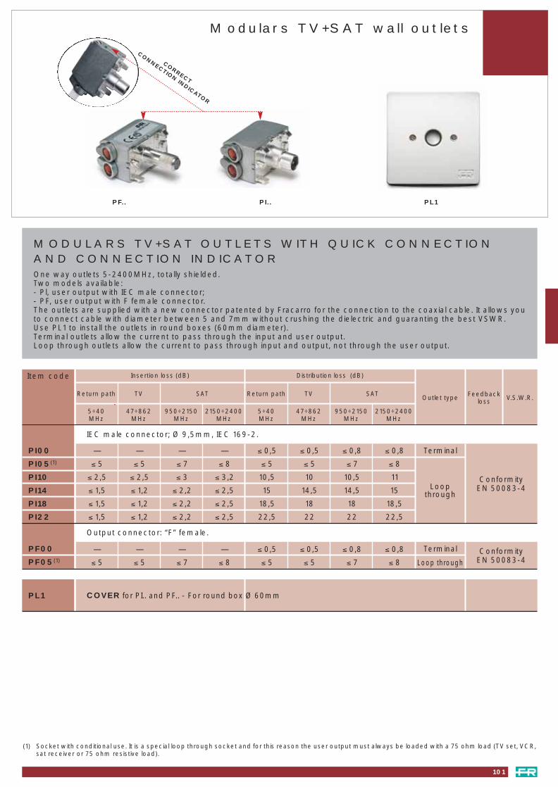
Insertion loss (dB) Distribution loss (dB)
MODULARS TV+SAT OUTLETS WITH QUICK CONNECTION AND CONNECTION INDICATOROne way outlets 5-2400MHz, totally shielded.Two models available:- Pl, user output with IEC male connector;- PF, user output with F female connector.The outlets are supplied with a new connector patented by Fracarro for the connection to the coaxial cable. It allows youto connect cable with diameter between 5 and 7mm without crushing the dielectric and guaranting the best VSWR.Use PL1 to install the outlets in round boxes (60mm diameter). Terminal outlets allow the current to pass through the input and user output.Loop through outlets allow the current to pass through input and output, not through the user output.
Item code
101
Modulars TV+SAT wall outlets
PL1PF.. PI..
(1) Socket with conditional use. It is a special loop through socket and for this reason the user output must always be loaded with a 75 ohm load (TV set, VCR,sat receiver or 75 ohm resistive load).
Terminal— — — — ≤ 0,5 ≤ 0,5 ≤ 0,8 ≤ 0,8
≤ 5 ≤ 5 ≤ 7 ≤ 8 ≤ 5 ≤ 5 ≤ 7 ≤ 8
≤ 2,5 ≤ 2,5 ≤ 3 ≤ 3,2 10,5 10 10,5 11
≤ 1,5 ≤ 1,2 ≤ 2,2 ≤ 2,5 15 14,5 14,5 15
≤ 1,5 ≤ 1,2 ≤ 2,2 ≤ 2,5 18,5 18 18 18,5
≤ 1,5 ≤ 1,2 ≤ 2,2 ≤ 2,5 22,5 22 22 22,5
ConformityEN 50083-4
V.S.W.R.Feedbackloss
Return path TV SAT Return path TV SAT
5÷40MHz
47÷862MHz
950÷2150 MHz
2150÷2400MHz
5÷40MHz
47÷862MHz
950÷2150 MHz
2150÷2400MHz
PI00
PI05(1)
PI10
PI14
PI18
PI22
IEC male connector; Ø 9,5mm, IEC 169-2.
Outlet type
Loopthrough
Terminal— — — — ≤ 0,5 ≤ 0,5 ≤ 0,8 ≤ 0,8
≤ 5 ≤ 5 ≤ 7 ≤ 8 ≤ 5 ≤ 5 ≤ 7 ≤ 8Conformity
EN 50083-4PF00
PF05(1)
Output connector: “F” female.
Loop through
PL1 COVER for PI.. and PF.. - For round box Ø 60mm
CORRECT
CONNECTION INDICATOR
087_114 distribution e service 23-09-2004 16:57 Pagina 101

102
Modulars TV+SAT outlets accessories
PLASTIC ADAPTERS FOR OUTLETS PI.., PF..
Item code
BT-TT
AVSNO
AV-SGR
AV-SBA
AV-SBL
LG-CR
VI-IDB
VI-ID
VI-80
VI-PL
BT-LIG
BT-LIV
BT-INT
BT-MA
BT-LU
BT-MAT
Type Packaging
Ticino Magic TT®
Ave Sis. 45 Noir®
Ave Sis. 45 Grigio®
Ave Sis. 45 Banquise®
Ave Sis. 45 Blanc®
Legrand Cross®
Viamar Idea Bianca®
Vimar Idea®
Vimar 8000®
Vimar Plana®
Ticino Light®
Ticino Living®
Ticino International®
Ticino Magic®
Ticino Luna®
Ticino Matix®
20
20
20
20
20
20
20
20
20
20
20
20
20
20
20
20
Plastic bag.
Plastic bag.
Plastic bag.
Plastic bag.
Plastic bag.
Plastic bag.
Plastic bag.
Plastic bag.
Plastic bag.
Plastic bag.
Plastic bag.
Plastic bag.
Plastic bag.
Plastic bag.
Plastic bag.
Plastic bag.
pcs
(®)All registered trademarks, are the property of their respective owners.
087_114 distribution e service 23-09-2004 16:57 Pagina 102

103
PR11
Connectors and accessories
SA..
ATTENUATORS - For attenuating signals that are too high. Input and output: 75ohm. Suitable for all TV bands.
FIXED - No d.c. through-line. I.E.C. coaxial connectors ∅ 9.5mm.
Attenuation 6dB - Packaging 10pcs
Attenuation 12dB - Packaging 10pcs
Attenuation 20dB - Packaging 10pcs
SA6
SA12
SA20
I.E.C. MALE COAXIAL CONNECTORS
SP1-SP3-SP4 AC5-AC6
SPV
PR1-PR3
GC1 CR75 CR75N
PR6 SP5 PR5
SP11
∅ mm
13 9,5
Packaging
pcs
Copper plated
screw clip shielded
x
x
x
x
x
x
x
x
x
x
x
x
x
x
x
x
100
100
100
100
10
100
10
1
SP1
SP3
SP4
SP5
SPV
AC5
AC6
SP11
Cable connector - straight
Cable connector - straight
Cable connector - straight
Cable connector - straight
Cable connector - with screw
For wall outlets - L-shaped
For wall outlets - L-shaped
For wall outlets - L-shaped
Item code
I.E.C. FEMALE COAXIAL CONNECTORSx
x
x
x
x
x
x
x
100
100
100
1
Cable connector - straight
Cable connector - straight
Cable connector - straight
Cable connector - with screw
For wall outlets - L-shaped
FA24
CR75N
GC1
Adjustable plastic strap for mast amplifiers: Es, EM, JS and JK series. For all weather.For mast mounting ∅ 60mm max. Packaging 100pcs
Resistive load 75ohm. Coaxial for TV - V.S.W.R. < 1.05 - for unused terminals. Packaging 100pcs
Resistive load 75ohm. Coaxial for TV - V.S.W.R. < 1.05 - for unused terminals. Packaging 100pcs
Cable connector - Packaging 100pcs
CR75
PLUG with 75ohm RESISTIVE LOAD - Insolated
SPI75 Coaxial - V.S.W.R. < 1.10 - for closing R.F. lines at 75ohm, can be used with D.C. Packaging 100pcs
EARTH TERMINAL BOARD
PRT1For earth connection of 6 coaxial cables of the TV distribution network. Best fitted close to the amplifier unit.Packaging 25pcs
Item code
ACCESSORIES
PR1
PR3
PR4
PR5
PR11
087_114 distribution e service 23-09-2004 16:57 Pagina 103
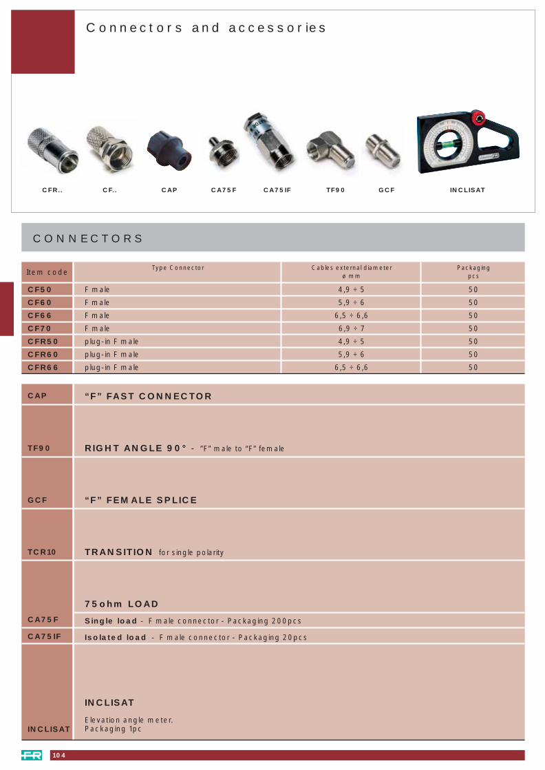
CONNECTORS
Item code
Connectors and accessories
INCLISATCFR.. CF.. CAP TF90 GCFCA75F CA75IF
Type Connector Cables external diameter Packagingø mm pcs
CF50
CF60
CF66
CF70
CFR50
CFR60
CFR66
F male 4,9 ÷ 5 50
F male 5,9 ÷ 6 50
F male 6,5 ÷ 6,6 50
F male 6,9 ÷ 7 50
plug-in F male 4,9 ÷ 5 50
plug-in F male 5,9 ÷ 6 50
plug-in F male 6,5 ÷ 6,6 50
TRANSITION for single polarity
75ohm LOAD
Single load - F male connector - Packaging 200pcs
Isolated load - F male connector - Packaging 20pcs
INCLISAT
Elevation angle meter.Packaging 1pcINCLISAT
CA75F
TF90
CA75IF
GCF
TCR10
RIGHT ANGLE 90° - ”F” male to “F” female
CAP “F” FAST CONNECTOR
“F” FEMALE SPLICE
104
087_114 distribution e service 23-09-2004 16:57 Pagina 104

Connectors and accessories
• SCREW IN CONNECTORS
PAS3212002 For cable with diel. ∅ of 4.8
external ∅ 6.8
• CONNECTORS WITH SEPARATE FERRULE
PAS3214001 Crimping hexagon:
11.5 for cable with ext. ∅ of 10.25
PAS3214012 Crimping hexagon:
11.5 for cable with diel. ∅ of 6.9
external ∅ 10.25 - Central contact
• CONNECTORS WITH INTEGRAL FERRULE
PAS3212012 Crimping hexagon:
8.2 For cable with diel. ∅ of 4.8
external ∅ 6.8
PAS3211401 Crimping hexagon:
6.8 for 4 in 1 cable
.. diel. ∅ 3.2 ext. ∅ 5
• WATERTIGHT CONNECTORS
PAS3212029 For cable with diel. ∅ of 4.7
ext. ∅ 7.2 max.
PAS3214039 For cable with diel. ∅ of 6.9
external ∅ 10.4 - Central contact
*(1)
• MISCELLANEOUS
PAS3230009 Angled connection male/female
PAS3230019 Straight connection female/female
PAS3231001 Straight connection male/male
PAS3213001 Current stop male/female
PAS3240009 75 ohms charge male
PAS6106001 6 dB ULB attenuator male /female
PAS6112001 12 dB ULB attenuator
(tilt 12 - 9 dB) male/female
• WATERTIGHT MALE CONNECTORS0475211 For cable with diel. ∅ of 7.5,
ext. ∅ of 11.1PAS3514002 For cable with diel. ∅ of 6.9
ext. ∅ 10.4PAS3512002 Crimping hexagon:
8.3 for cable with diel. ∅ of 4.7 external diam. 7.1
PAS3515002 For cable with diel. ∅ of 14.9 external ∅ 19.8
• MISCELLANEOUSPAS3530001 “3.5/12” transition female -
F male0475100 Female/ female connector0475200 75ohms charge male
insulated
• MALE CONNECTORS WITH FLOATING NUTAND BOLT AND SEPARATE FERRULE
PAS3312002 Crimping hexagon:8.3 for cable with diel. ∅ of 4.8 external ∅ 6.8
PAS3314002 Crimping hexagon:11.5 for cable with diel. ∅ of 6.9external ∅ 10.4
• PLASTIC JACK PLUGSPAS3112032 Blue male jack plugPAS3122032 Blue female jack plug
• MISCELLANEOUSPAS3170001 Current stop female/malePAS3123002 T-shaped co-axial suitable for
female input/ 2 male outputsPAS3113002 T-shaped co-axial suitable for
male input/ 2 female outputsPAS3111001 Angled blue male connection0275307 Co-axial connection
• PLASTIC JACK PLUGS0575107 Cream female jack plug
0575207 Cream male jack plug
• MISCELLANEOUSPAS3623002 T-shaped co-axial suitable for
female input / 2 male outputs
PAS3666001 Crimping pliers, hexagonal impressions
for cables with ext. ∅ of 5 / 6.8/ 10.4mm.
7188293 Flaring tool handle with adapter
7188295 Flaring tool for cable with diel. ∅ of 4.8
PAS3664001 Flaring tool for cable with diel. ∅ of 6.9
7188297 Flaring tool for cable with diel. ∅ of 14.9
F CONNECTORS 9.52mm diam CO-AXIAL JACKPLUGS AND CONNECTIONS
TOOLS
9 mm diam CO-AXIAL JACKPLUGS AND CONNECTIONS
“E” CONNECTORS
3.5/12 CONNECTORS**(2)
*(1) Connectors - compression
PAS3212 B for cables Ø diel. 4.8 Ø ext. 6,8
PAS3214 B for cables Ø diel. 7.1 Ø ext. 10
**(2) PAS3364 B tool for compression fit connector PAS3212 B
PAS3364 D tool for compression fit connector PAS3214 B
105
087_114 distribution e service 23-09-2004 16:57 Pagina 105

Cellular co-axial cables
Don’t take any risks. Using these cables in all your installation.
You can be sure:
• that you are installing cables that comply with the new EN-50117 standard
• that your installations will be guaranteed for many years.
• all the cables have insulation that complies whith the safety standard’s ageing tests
• your installation will be protected against rodents
• cables are:
Class B : screening efficiency > 75dB or Class A: screening efficiency > 85dB
Class B cables recommendedfor single installations
Class A cables recommendedfor installations in flats
and offices
ALL OUR CELLULAR CO-AXIAL CABLES ARE MANUFACTURED IN ACCORDANCEWITH THE PHYSICAL PROCESS
Cla
ss B
Cla
ss A
Cla
ss A
Cla
ss A
Cla
ss A
Cla
ss A
EXTERNAL DIAMETER 5mm 6,7mm 6,6 mm 6,7mm 6,8mmTYPE PVC white 23VAtC 19VAtC 17VAtC 19VAtC 19VAtC 17VAtC 19VAtC 17VAtC100m PAS4036104 PAS4037104 PAS4016112 PAS4016102 PAS4017101 PAS4006101 PAS4007111200 / 250m PAS4005201 PAS4016252 PAS4017251 PAS4007251500m PAS4036504 PAS4016502 PAS4006501TYPE PE black 19PAtC 17PAtC 19PAtC 17PAtC100m PAS4136104 PAS4037504 PAS4116102 PAS4117101 PAS4106101 PAS4107111250m PAS4117251 PAS4107251500m PAS4136504 PAS4116502 PAS41065011000m PAS4036004COREDiameter (mm) 0,8 1,0 1,13 1,0 1,0 1,13 1,0 1,13Composition Copper Copper Copper Copper Copper Copper Copper CopperDIELECTRIC Bleu BleuDiameter (mm) 3,2 4,6 4,6 4,7 4,6 4,8 4,6 4,8METAL STRIP Double metal strip: Double metal strip:Composition Triplex Alu Triplex Alu Triplex Alu Triplex Alu Triplex Alu Triplex Alu Triplex Alu Triplex+Duplex AluRecouvrement 100 % 100 % 100 % 100 % 100 % 100 % 100 % 100 %TRESSEComposition Tin plated copper Tin plated copper Aluminium Tin plated copper Tin plated copper Tin plated copper Tin plated copper Tin plated copperCovering 46 % 36 % 36 % 40 % 40 % 40 % 40 % 40 %ATTENUATIONnominal (dB/100m) at47MHz 5,6 4,7 4,1 4,6 4,5 4,1 4,5 4,1470MHz 17,8 14,1 13,1 13,5 13,6 13,1 13,6 13,1800MHz 23,3 18,7 17,0 19,0 18,5 17 18,5 17860MHz 24,6 19,4 17,7 19,8 19,1 17,7 19,1 17,7950MHz 25,9 20,5 18,6 20,9 20,2 18,6 20,2 18,62150MHz 40,5 32,2 29,1 33,3 31,9 29,1 31,9 29,12400MHz 42,8 36,1 30,7 35,5 33,7 30,7 33,7 30,7Screening efficiency Class A Class B Class B Class A Class A Class A Class A Class A
> 85dB > 75dB > 75dB > 85dB > 85dB > 85dB > 90dB > 90dBComplies with EN 50-117 and NF 90-131
TWIN Special DTT
106
087_114 distribution e service 23-09-2004 16:57 Pagina 106

Cellular co-axial cables
(*) External gain, black PVC anti UV treated, internal cables coloured PE
Cla
ss A
Cla
ss A
Cla
ss A
Cla
ss A
Cla
ss A
Cla
ss A
Cla
ss A
Cable operatorapproved
ALL OUR CELLULAR CO-AXIAL CABLES ARE MANUFACTURED IN ACCORDANCEWITH THE PHYSICAL PROCESS
EXTERNAL DIAMETER Copper cables 10,25mm 20 mm Multiple cablesTYPE white PVC 18VREC 11VAtC 11VRtC 4 in 1 5 in 1 9 in 150m PAS4004059100m PAS4009101 PAS4004112 PAS4004102 PAS4004109250m PAS4066251 PAS4009251500m PAS4009501 PAS4000511TYPE PE black 18PREC 11PAtC 11PRtC 6PRtC100m PAS4109101 PAS4304102*250m PAS4166251 PAS4109251500m PAS4109501 PAS4110511700m or cut PAS4102001Autopate PAS4159501
/ 500mCORE Diameter (mm) 1,02 1,7 1,7 3,4 1,0 1,0 1,13
Composition Copper Copper Copper Copper CopperDIELECTRIC diameter (mm) 4,5 7,35 6,9 14,9 4,6 4,6 4,6METAL STRIP Composition Copper Triplex Alu Copper Copper Triplex Alu Triplex Alu Triplex Alu
Covering 100 % 100 % 100 % 100 % 100 % 100 % 100 %BRAIDING Composition Copper Tin plate copper Copper Copper Tin plate copper Tin plate copper Tin plate copper
Covering 65% 56 % 56 % 60 % 40 % 40 % 40 %NOMINAL ATTENUATION(dB/100m) at: 47MHz 4,1 2,5 2,5 1,2 4,6 4,6 4,1470MHz 13,3 8,4 8,3 4,3 14,0 14,0 13,1800MHz 17,8 11 11 5,7 18,8 18,8 17860MHz 18,5 11,5 11,5 6 19,5 19,5 17,7950MHz 19,4 12,2 12,1 6,3 20,6 20,6 18,62150MHz 30,9 19,5 19 10 32,6 32,6 29,12400MHz 32,6 20,7 20,4 10,6 34,6 34,6 30,7
Screening efficiency Class A Class A Class A Class A Class A Class A Class A> 90dB > 85dB > 85dB > 85dB > 85dB > 85dB > 90dB
107
087_114 distribution e service 23-09-2004 16:57 Pagina 107

105 - 0275307105 - 475100105 - 475200105 - 475211105 - 575107105 - 575207105 - 7188293105 - 7188295105 - 718829710 219535 10/3539R10 219540 10/4046R10 219547 10/4753R10 219554 10/5461R10 219562 10/6269R10 219486 10/86096010 219521 10ALFA/R10 219524 10BETA/R11 219404 10BL411 219445 10BL4511 219405 10BL510 219531 10DELTA/R10 219527 10GAMMA/R11 219506 10RD4F11 219546 10RD45F11 219506 10RD5F10 219640 20/404610 219631 20DELTA11 219604 20BL411 219645 20BL4511 219605 20BL511 219704 20RD411 219745 20RD4511 219706 20RD4F11 219746 20RD45F11 219705 20RD511 219707 20RD5F6 212273 2A6 212204 2B6 212271 2FM6 212373 3A6 212304 3B6 212370 3C6 212404 4B7 218701 4D_F7 218702 4E_F7 218706 4E512_F7 218703 4F_F7 218704 4G_F7 218705 4H_F7 218711 6D_F7 218712 6E_F7 218717 6E12_F7 218718 6E512_F7 218713 6F_F7 218714 6G_F7 218715 6H_F7 218716 6H1_F38 227310 ABLA10138 227312 ABLA10238 227314 ABLA3RT103 290305 AC5103 290306 AC640 289100 AL50S40 289112 AM50N40 289113 AM100N40 289119 AM102N86 AMP2620000 AMP262000086 AMP2630026 AMP263002682 289605 AMP512AL82 289606 AMP512AM83 289602 AMP522AL83 289604 AMP522AM83 289601 AMP522PL83 289603 AMP522PM73 AMP8331 AMP833173 AMP8331A AMP8331A39 AMP9200 AMP920039 AMP9201 AMP920161 AMP9202U AMP9202U61 AMP9202W AMP9202W
73 AMP9244A AMP9244A72 271031 AMP925472 271033 AMP9254A73 AMP9284A AMP9284A72 271032 AMP929439 AMP9300 AMP930039 AMP9301 AMP930139 AMP9311 AMP931164 AMP9404A AMP9404A64 AMP9404B AMP9404B73 AMP9444 AMP944473 AMP9444A AMP9444A86 AMP9501 AMP950186 AMP9501S AMP9501S80 AMP9602 AMP960286 AMP9603 AMP960374 AMP9724 AMP972480 235051 AMP976286 235052 AMP976364 235053 AMP976473 AMP9853 AMP985373 AMP9893 AMP989321 293301 AN16 213001 ANT1200A8 213002 ANT30305078 213003 ANT30308108 213004 ANT30605108 213005 ANT30705078 213006 ANT30708108 213007 ANT310051012 - ANT410001212 - ANT411381212 - ANT411691215 ANT41538 ANT4153815 ANT41569 ANT4156915 ANT41600 ANT4160015 ANT42200 ANT4220012 ANT4220012 ANT422001215 ANT42238 ANT4223812 - ANT422381212 - ANT422691217 ANT5093802 ANT509380217 ANT5094702 ANT509470217 ANT5096902 ANT509690217 ANT5143802 ANT514380217 ANT5144702 ANT514470217 ANT5146902 ANT514690288 289253 AS1088 284013 AS2063 288011 AVM163 288012 AVM363 288010 AVM45102 280745 AV-SBA102 280746 AV-SBL102 280744 AV-SGR102 - AVSNO21 293400 BA621 280674 BA91478 289349 BFO-SC-APC14 217850 BLU220F14 217857 BLU220PLUS14 217851 BLU224F14 217852 BLU225F14 217853 BLU420F14 217854 BLU424F14 217855 BLU425F14 217856 BLU920F9 218038 BLV4F9 218058 BLV6F78 289360 BR2-AA78 289359 BR2-PA78 289362 BR4-AA78 289361 BR4-PA29 289409 BSTE429 289378 BSTE529 289247 BSTE829 289408 BSTE9102 280754 BT-INT102 280752 BT-LIG102 280753 BT-LIV
102 280755 BT-MA102 280756 BT-LU102 280757 BT-MAT102 280742 BT-TT10 219600 CA154 289085 CA75F104 289085 CA75F104 289089 CA75IF81 223050 CAA0832C4090 220401 CAD10190 220402 CAD10290 220644 CAD10490 220451 CAD1190 220452 CAD1290 220453 CAD1390 220454 CAD14104 280347 CAP100 280741 CAPL90 220660 CD1190 220670 CD1290 220651 CD14190 220652 CD14290 220654 CD14490 220671 CD20190 220672 CD20290 220674 CD20490 220681 CD26190 220682 CD26290 220684 CD26429 289243 CDPU4Z29 289249 CDPU8Z29 289143 CDPUTZ29 289191 CDPUZ29 289192 CDPUZP104 280340 CF50104 280341 CF60104 280342 CF66104 280346 CF70104 280343 CFR50104 280344 CFR60104 280345 CFR6629 289144 CHVU4Z29 289339 CQ0329 289340 CQ03-F29 289338 CQ0529 289337 CQD0329 289335 CQD03-F29 289336 CQD05103 290010 CR75103 289536 CR75N54 289549 CROSS-RJ4529 289345 CSU0329 289344 CSU03-F29 289342 CT0329 289343 CT03-F29 289341 CT0554 280376 CVDC506 213010 DAB92 280710 DE1-1092 280711 DE1-1492 280712 DE1-1892 280713 DE1-2292 280714 DE2-1092 280715 DE2-1492 280716 DE2-1892 280717 DE2-2293 280718 DE4-1293 280719 DE4-1493 280720 DE4-1893 280721 DE4-2293 280722 DE6-1693 280723 DE6-2093 280724 DE6-2593 280725 DE8-1693 280726 DE8-2093 280727 DE8-2516 213017 DELTA50016 213018 DELTA80026 289035 DFA26 289295 DFO80C
page code item codepage code item code page code item code page code item code
26 289294 DFO100C26 289199 DFO120N24 211001 DFP8524 211002 DFP85R24 211003 DFPDIGIT25 211111 DGTX1025 211112 DGTX10-A25 211116 DGTX10-GA25 211115 DGTX10-RA25 211101 DIGIT25 211104 DIGIT-A28 211108 DIGIT-AK25 211109 DIGIT-ASKY25 211102 DIGIT-G25 211105 DIGIT-GA28 211107 DIGITK25 211103 DIGIT-R25 211106 DIGIT-RA23 289560 DOMUS88 289203 DSQ288 289246 DSQF37 227160 EK6/Q-34537 227101 EK6R1345U37 227102 EK6R1345UO37 227104 EK6R1345US37 227103 EK6RP4537 227105 EK6RP45S37 227106 EK6RPUU37 227108 EK6RPUUO34 226905 ES1/Q34 226909 ES1/RVU34 226913 ES2/Q34 226917 ES2/RU34 226912 ES2RT32 226820 ES345/4332 226805 ES54V32 226803 ESP232 226804 ESV4532 226807 ESV45S32 226801 ESVU32 226806 ESVUU32 226802 ESVU232 226811 ESVU22103 293404 FA2433 257900 FE5U62 FIL132200 FIL13220062 FIL132201 FIL13220162 FIL141200 FIL14120062 FIL151200 FIL15120062 FIL161200 FIL16120062 FIL171200 FIL17120062 FIL181200 FIL18120062 FIL191200 FIL19120062 FIL191201 FIL191201103 - FIXED33 226745 FUS45103 290030 GC1104 289544 GCF88 289147 INBS2104 280690 INCLISAT89 220322 IP233 290018 IZ280 223020 J11A80 223021 J22B38 223032 JA21R38 223049 JAX13DC59 223070 JB8R1345U59 223075 JB8RL345U59 223073 JB8RPUU59 223071 JBR1345US59 223054 JH7QR34559 223051 JH7R1345U59 223056 JH7R1345US59 223051 JH7RL345U59 223052 JH7RP4559 223053 JH7RPUU37 223254 JK6QR34537 223251 JK6R1345U37 223256 JK6R1345US37 223252 JK6RP45
Index of products
108
087_114 distribution e service 23-09-2004 16:57 Pagina 108

109
37 223258 JK6RP45S37 223253 JK6RPUU37 223259 JK6RPUUO34 223101 JS2RT33 223109 JSVU352 288001 K1150-157053 282102 K1-246 - K120/..47 - K120/…DT47 - K120A/..52 288002 K1720-215052 288004 K1940-215052 288003 K2015-215053 282101 K2-853 293433 KA60053 293434 KA80050 282351 KCMU50 282353 KCMU/M50 282352 KCMU/S50 282354 KCMV50 282356 KCMV/M50 282355 KCMV/S45 282618 KCP53 289539 KD10048 282641 KDFAV48 282639 KDFU48 282640 KDFV49 270615 KDRTT/UH-CD49 270614 KDRTT/VH-CD49 270602 KDTS/VL-C246 270193 KF/..47 - KF/…DT46 270058 KF/DAB47 270054 KFB447 270055 KFB552 - KFT/…52 282599 KIF52 282598 KIF-1051 270510 KK1-U51 270534 KK3-451 270543 KK4-351 270553 KK5-351 270563 KK6-353 270018 KP1553 270017 KP3553 270016 KP6054 289334 KPN37R54 289245 KPN4254 289244 KPN5154 289537 KRF1554 289538 KRF4577 289365 KRX215077 270676 KRX2150L77 270672 KRX-RC77 270679 KSP1_277 270680 KSP1_453 282103 KSST45 282619 KTLC54 282735 KTP77 289366 KTX215077 270675 KTX2150L77 270671 KTX-RC51 270050 KW33B51 270053 KW33C51 270059 KW35E51 270051 KW44C51 270056 KW53051 270057 KW54052 282104 KX12552 282106 KX125E52 282105 KX125NT102 280747 LG-CR18 216134 LP34HV18 216168 LP345HV18 216167 LP345MHV18 216147 LP45HV18 216148 LP45N18 216107 LP5HV18 217349 LPV345HV36 223121 MAP102
36 223123 MAP10335 223111 MAP10435 223120 MAP10535 223122 MAP10635 223110 MAP10735 223112 MAP10835 223160 MAP10936 223162 MAP20136 223151 MAP20235 223148 MAP20435 223125 MAP20535 223150 MAP20635 223147 MAP20735 223161 MAP20836 223149 MAP20935 223124 MAP21036 223164 MAP30035 223130 MAP30335 223131 MAP30436 223155 MAP30635 223146 MAP31135 223142 MAP31235 223152 MAP31336 223153 MAP31435 223163 MAP31535 223141 MAP40036 223166 MAP40235 223133 MAP50035 223137 MAP50135 223134 MAP50235 223138 MAP50382 289607 MAV302382 289608 MAV552382 289609 MAV652382 289610 MAX302382 289611 MAX552382 289612 MAX652329 289306 MBU4Z29 289307 MBUTZ29 289129 MBUZ60 235000 MBX000160 235002 MBX554160 235004 MBX555060 235017 MBX5550S60 235015 MBX555160 235001 MBX574160 235003 MBX575060 235007 MBX5750S60 235014 MBX575260 235016 MBX585160 235006 MBX774160 235005 MBX775060 235018 MBX7750S30 289410 MC1-TV30 289411 MC3-SAT30 289413 MC7-TVSAT84 - MCS0484 - MCS0884 289613 MDA304784 289614 MDA425484 289615 MDA557384 289616 MDA608084 289617 MDA658732 225982 MEF/..85 289619 MEX800/0685 289620 MEX800/0885 289621 MEX802/0685 289622 MEX802/0885 289623 MEX804/0685 289624 MEX804/0885 289625 MEX806/0685 289626 MEX806/0884 289627 ML0184 289628 ML0254 236505 MP04AF54 236506 MP05AF54 236504 MP13AF84 289629 MP2054 236507 MP45AF54 236508 MPCCF
85 289630 MPG00 85 289631 MPG01 85 289632 MPG02 85 289633 MPG03 85 289634 MPG0485 289635 MPG05 85 289636 MPG0685 289637 MPG0785 289638 MPG0885 289639 MPG09 85 289640 MPG10 85 289641 MPG1285 289642 MPG1485 289643 MPG16 85 289644 MPG1885 289645 MPG2085 289646 MPG22 82 289647 MPX3082 289648 MPX5582 289649 MPX6584 289650 MS10084 289651 MS10184 289652 MS11084 289653 MS11484 289654 MS11884 289655 MS20684 289656 MS40463 289332 MU9063 289331 MV9033 226400 MXST78 289403 OPB24I78 289404 OPB24IR78 289405 OPB8I78 289398 OPC4IM78 289397 OPC4OM78 289400 OPC4OMA78 289396 OPC8IM78 289401 OPC8OM78 289399 OPC8OMA78 289402 OPO12P23 289598 ORION28 211308 P80APK28 211313 P80RCIK28 211314 P80RCIK-DF28 211309 P80RFK28 211310 P80RFK-DF28 211220 P85AK28 211221 P85AKSKY25 211213 P85ASKYX1025 211217 P85GX10-A25 211212 P85GX10-B28 211219 P85K25 211216 P85RX10-A25 211211 P85RX10-B25 211209 P85X1025 211210 P85X10-A91 280701 PA291 280703 PA391 280702 PA491 280704 PA691 280705 PA885 289661 PAD-BOX99 PAS0021411 PAS002141199 PAS0021511 PAS002151199 PAS0021D PAS0021D99 PAS0025D PAS0025D99 PAS0032 PAS003299 PAS0032101 PAS003210199 PAS0032111 PAS00321199 PAS0032D PAS0032D99 PAS0032Q PAS0032Q99 PAS0042 PAS004286 PAS0227533 PAS022753386 PAS0227555 PAS022755586 PAS0227565 PAS022756533 PAS0302 PAS030233 PAS0303 PAS030333 PAS0303011 PAS030301133 PAS0311 PAS031133 PAS0312 PAS0312
43 PAS0322001 PAS032200143 PAS0322011 PAS032201162 PAS0436301 PAS043630162 PAS0437301 PAS043730162 PAS0449401 PAS044940194 PAS1222011 PAS122201197 PAS1223001 PAS122300196 PAS1224 PAS122495 PAS1226023 PAS122602394 PAS1232011 PAS123201197 PAS1233001 PAS123300195 PAS1236023 PAS123602394 PAS1242011 PAS124201197 PAS1243001 PAS124300196 PAS1244 PAS124496 PAS1244A PAS1244A95 PAS1246023 PAS124602397 PAS1263001 PAS126300197 PAS1283001 PAS128300196 PAS1284001 PAS128400195 PAS1286023 PAS128602396 PAS1323 PAS132396 PAS1323A PAS1323A106 PAS136104 PAS13610474 PAS1623 PAS162374 PAS1623D PAS1623D74 PAS1923 PAS192374 PAS1923D PAS1923D94 PAS2212111 PAS221211194 PAS2212211 PAS221221194 PAS2212311 PAS221231194 PAS2212411 PAS221241194 PAS2212511 PAS221251197 PAS2213211 PAS221321197 PAS2213311 PAS221331197 PAS2213411 PAS221341195 PAS2216053 PAS221605395 PAS2216083 PAS221608395 PAS2216113 PAS221611395 PAS2216143 PAS221614395 PAS2216173 PAS221617395 PAS2216203 PAS221620395 PAS2216233 PAS221623395 PAS2216263 PAS221626395 PAS2216293 PAS221629394 PAS2222111 PAS222211194 PAS2222211 PAS222221194 PAS2222311 PAS222231194 PAS2222411 PAS222241194 PAS2222511 PAS222251194 PAS2222611 PAS222261197 PAS2223211 PAS222321197 PAS2223311 PAS222331197 PAS2223411 PAS222341197 PAS2223511 PAS222351197 PAS2223611 PAS222361195 PAS2226083 PAS222608395 PAS2226113 PAS222611395 PAS2226143 PAS222614395 PAS2226173 PAS222617395 PAS2226203 PAS222620395 PAS2226233 PAS222623395 PAS2226263 PAS222626395 PAS2226293 PAS222629394 PAS2242211 PAS224221194 PAS2242311 PAS224231194 PAS2242411 PAS224241194 PAS2242511 PAS224251194 PAS2242811 PAS224281198 PAS2243211 PAS224321198 PAS2243311 PAS224331198 PAS2243411 PAS224341198 PAS2243511 PAS224351198 PAS2243611 PAS224361195 PAS2246113 PAS224611395 PAS2246143 PAS224614395 PAS2246173 PAS224617395 PAS2246203 PAS224620395 PAS2246233 PAS224623395 PAS2246263 PAS2246263
Index of products
page code item codepage code item code page code item code page code item code
087_114 distribution e service 23-09-2004 16:58 Pagina 109

95 PAS2246293 PAS224629394 PAS2262811 PAS226281198 PAS2263211 PAS226321198 PAS2263311 PAS226331198 PAS2263411 PAS226341194 PAS2282811 PAS228281198 PAS2283211 PAS228321198 PAS2283311 PAS228331198 PAS2283411 PAS228341195 PAS2286143 PAS228614395 PAS2286173 PAS228617395 PAS2286203 PAS228620395 PAS2286233 PAS228623395 PAS2286263 PAS228626395 PAS2286293 PAS228629374 PAS2613 PAS261374 PAS2623 PAS262374 PAS2713 PAS271374 PAS2813 PAS281374 PAS2913 PAS2913105 PAS3111001 PAS3111001105 PAS3112032 PAS3112032105 PAS3113002 PAS3113002105 PAS3122032 PAS3122032105 PAS3123002 PAS3123002105 PAS3170001 PAS3170001105 PAS3211401 PAS3211401105 PAS3212002 PAS3212002105 PAS3212012 PAS3212012105 PAS3212029 PAS3212029105 PAS3213001 PAS3213001105 PAS3214001 PAS3214001105 PAS3214012 PAS3214012105 PAS3214039 PAS3214039105 PAS3230009 PAS3230009105 PAS3230019 PAS3230019105 PAS3231001 PAS3231001105 PAS3240009 PAS3240009105 PAS3312002 PAS3312002105 PAS3314002 PAS3314002105 PAS3512002 PAS3512002105 PAS3514002 PAS3514002105 PAS3515002 PAS3515002105 PAS3530001 PAS3530001105 PAS3623002 PAS3623002105 PAS3664001 PAS3664001105 PAS3666001 PAS3666001107 PAS4000511 PAS4000511107 PAS4004059 PAS4004059107 PAS4004102 PAS4004102107 PAS4004109 PAS4004109107 PAS4004112 PAS4004112106 PAS4005201 PAS4005201106 PAS4006101 PAS4006101106 PAS4006501 PAS4006501106 PAS4007111 PAS4007111106 PAS4007251 PAS4007251107 PAS4009101 PAS4009101107 PAS4009251 PAS4009251107 PAS4009501 PAS4009501106 PAS4016102 PAS4016102106 PAS4016112 PAS4016112106 PAS4016252 PAS4016252106 PAS4016502 PAS4016502106 PAS4017101 PAS4017101106 PAS4017251 PAS4017251106 PAS4036004 PAS4036004106 PAS4036104 PAS4036104106 PAS4036504 PAS4036504106 PAS4037104 PAS4037104106 PAS4037504 PAS4037504107 PAS4066251 PAS4066251107 PAS4102001 PAS4102001106 PAS4106101 PAS4106101106 PAS4106501 PAS4106501106 PAS4107111 PAS4107111106 PAS4107251 PAS4107251107 PAS4109101 PAS4109101107 PAS4109251 PAS4109251107 PAS4109501 PAS4109501
107 PAS4110511 PAS4110511106 PAS4116102 PAS4116102106 PAS4116502 PAS4116502106 PAS4117101 PAS4117101106 PAS4117251 PAS4117251106 PAS4136504 PAS4136504107 PAS4159501 PAS4159501107 PAS4166251 PAS4166251107 PAS4304102 PAS430410299 PAS5321 PAS5321105 PAS6106001 PAS6106001105 PAS6112001 PAS611200158 PAS6420001 PAS642000158 PAS6480001 PAS648000158 PAS9168001 PAS916800154 289548 PATCH-RJ4524 211201 PENTA8525 211205 PENTA85-A25 211203 PENTA85G25 211206 PENTA85G-A25 211204 PENTA85R25 211207 PENTA85R-A101 220761 PF00101 PFO5 PFO585 289658 PG11-3,5/1285 289659 PG11-5/885 289657 PG11-CP85 289660 PG11-F20 289540 PG20101 220751 PI00101 220752 PI05101 220753 PI10101 220754 PI14101 220755 PI18101 220756 PI22101 280736 PL1100 280737 PL289 220375 PP1289 220375 PP12DC89 220376 PP1389 220392 PP1489 220392 PP14DC103 290451 PR1103 290365 PR11103 290453 PR3103 290452 PR4103 290454 PR5100 280730 PRI00100 280731 PRI06100 280732 PRI10100 280733 PRI14100 280734 PRI18100 280735 PRI22103 210095 PRT140 289563 PSU34140 289564 PSU34240 289561 PSU41140 289562 PSU41226 289293 PT100AC26 289291 PT100C26 289297 PT100CRX1022 293104 PT422 293106 PT622 293108 PT828 211305 PT80ACK26 289190 PT85N19 217416 PU1619 217403 PU4A19 217404 PU419 217405 P5419 217408 PU819 217409 PU8V20 210050 PV520 210011 PV1020 210022 PV2020 210064 PVF-6020 210002 PVP20 210065 PVZ-6026 289299 RO100ACX626 289289 RO100ACX25
26 289286 RO100CGX626 289287 RO100CRX626 289298 RO100CX626 289288 RO100CX2526 289197 RO120N26 289138 RO120NX526 289139 RO15026 280610 RO60AX1026 211307 RO80ACX1026 289277 RO80ACX5026 289276 RO80APX3026 289270 RO80APX10026 289283 RO80APX20026 289272 RO85GX5026 289273 RO85RX5026 289211 RO85X5021 289182 RPP60103 220113 SA12103 220121 SA20103 220107 SA627 SAT12121M SAT12121A27 SAT12181A SAT12181A27 SAT12901 SAT1290130 289258 SAT-BUSTER27 SCC1590 SCC159033 226707 SF433 226708 SF558 SIG125001 SIG12500156 SIG8123001 SIG812300157 SIG8165001 SIG816500157 SIG8166001 SIG816600157 SIG8167001 SIG816700157 SIG8168001 SIG816800157 SIG8600001 SIG860000157 SIG8613101 SIG861310157 SIG8614101 SIG861410157 SIG8622201 SIG862220157 SIG8623201 SIG862320157 SIG86242201 SIG8624220155 SIG8690001 SIG869000157-58 SIG8690001 SIG869000158 SIG9112001 SIG911200158 SIG9113001 SIG911300158 SIG9122001 SIG912200158 SIG9124001 SIG912400156 SIG9151001 SIG915100156 SIG9152001 SIG915200156 SIG9153001 SIG915300156-58 SIG9167001 SIG916700155 SIG9190 SIG919042 SIG9306UN SIG9306UN43 SIG9306VN SIG9306VN103 290351 SP1103 290361 SP11103 290353 SP3103 290352 SP4103 290354 SP5103 256076 SPI7572 289087 SPS1750103 289530 SPV21 289280 ST25M21 289281 ST45M21 289173 ST50C21 289282 STF21 289174 STK21 289204 STM.74 SWI1201A SWI1201A70 271071 SWI1201B70 271073 SWI1301B70 271072 SWI1401B70 271074 SWI1501B70 271011 SWI3504A70 271008 SWI3504A1070 271013 SWI3504P70 271012 SWI3506A70 271009 SWI3506A1070 271014 SWI3506P70 271016 SWI3506T70 271017 SWI3508A 70 271010 SWI3508A10
70 271018 SWI3508P70 271019 SWI3508T71 271021 SWI3904A71 271022 SWI3904P71 271023 SWI3904T71 271024 SWI3906A71 271025 SWI3906P71 271026 SWI3906T71 271027 SWI3908A71 271028 SWI3908P71 271029 SWI3908T69 SWI4404-00 SWI4404-0069 SWI4404-08 SWI4404-0869 271022 SWI4404-1769 SWI4406-00 SWI4406-0069 SWI4406-08 SWI4406-0869 SWI4406-17 SWI4406-1766 271041 SWI5506A66 271042 SWI5508A66 271043 SWI5512A66 SWI5516A SWI5516A66 271052 SWI5908A66 271053 SWI5912A66 SWI5916A SWI5916A73 SWI6504 SWI650473 SWI6506 SWI650673 SWI6508 SWI650873 SWI6512 SWI651273 SWI6516 SWI651673 SWI6904 SWI690473 SWI6906 SWI690673 SWI6908 SWI690873 SWI6912 SWI691267 SWI7504 SWI750467 SWI7504E SWI7504E67 SWI7506 SWI750667 SWI7506E SWI7506E67 SWI7508 SWI750867 SWI7508E SWI7508E67 SWI7512 SWI751267 SWI7512E SWI7512E67 SWI7516 SWI751667 SWI7516E SWI7516E68 SWI7904 SWI790468 SWI7904F SWI7904F68 SWI7906 SWI790668 SWI7908 SWI790868 SWI7908F SWI7908F68 SWI7912 SWI791268 SWI7912F SWI7912F70 271000 SWM1305A104 281031 TCR10104 289543 TF9054 289550 TF-RCA54 289551 TIEC-F22 293140 TK422 293150 TK532 210150 TM522 293115 TN1522 293125 TN2522 293132 TN3254 289545 TRDIN-RJ54 289542 TRF54 289546 TRRJ-DIN54 289547 TWIN-RJ4523 289597 VENUS23 289593 VENUS-3823 289596 VENUS-B23 289594 VENUS-P23 289595 VENUS-S102 280750 VI-80102 280749 VI-ID102 280748 VI-IDB102 280751 VI-PL21 293302 ZC221 293320 ZC2021 293330 ZC321 289541 ZM20
110
Index of products
page code item codepage code item code page code item code page code item code
087_114 distribution e service 23-09-2004 16:58 Pagina 110
Fracarro customer service
Customer services - Catalogues and brochures
FRNews - Web
Software
Page 112113114
087_114 distribution e service 23-09-2004 16:58 Pagina 111

Since 1933 Gruppo Fracarro has been offering its customers high quality products andsolutions renowned for its innovation and technology. To expand into the internationalmarket, along with Fracarro Iberica S.A., Philips SMATV was acquired and FracarroFrance, Fracarro (UK) Ltd and Fracarro Portugal were established. With a Fracarro agency in Thailand, a representative office in Moscow and a network ofdistributors worldwide, Fracarro isnow even closer to the market.
As a market leader in the receptionand distribution of audio-video-data signals and security, Fracarrois able to provide comprehensiveinformation and assistance world-wide. It also offers professionalassistance for pre/post sales,technical training and manuals tocontinually update information andprofessional growth, as well ascreating software for projectdesigns.
Ufficio di RappresentanzaMosca
Catalogues and brochures
In the “SMATV CATALOGUE” you can find the whole range of Fracarro solutions forsignals reception and distribution both for individual and collective systems.Specific brochures provide technical information for each product range, focusing on theadvantages of Fracarro systems.
Fracarro customer service
112
HEADEND AMPLIFIER MBX SERIE
MULTIBAND AMPLIFIER
087_114 distribution e service 23-09-2004 16:58 Pagina 112

113
Fracarro customer service
WEB
Through our web site we provide technicalassistance and specific information about ourproducts and services. In the download areayou can find completed projects designedwith our exclusive software, as well as productmanuals and catalogues that can be viewedon line.
www.fracarro.comwww.fracarro.com
www.fracarro.com
FRNews
Group news, product updatings anduseful information can be received
directly at home through ourmagazine FRNews.
Enter our web site to require yourcopy and be always up to date
with the latest news.
087_114 distribution e service 23-09-2004 16:58 Pagina 113

Software
Fracarro has recently developed FRDesigner, a new software systemwhich enables you to easily design a complete system for thereception and distribution of audio-video-data signals. All theinformation you need will be included in your project, fromsignal values to product costs and estimated manpower.Combining technical calculation and currency valueswith the highest accuracy, FRDesigner will edit a defini-tive and complete offer which you can simply submit toyour customer.
Fracarro customer service
087_114 distribution e service 23-09-2004 16:58 Pagina 114