Embed Size (px)
Citation preview

SMD COILS / 贴片线圈
SMD Common Mode Choke Coils / 共模线圈电感
EMI Filters Common Mode Choke - A CPWC Series / 共模EMI滤波电感 --------- 1
A CB4F Series ------------------------------------------------------------------------------------- 4
A CB4FL Series ------------------------------------------------------------------------------------ 6
A CB5F Series --------------------------------------------------------------------------------------- 8
A CB5FL Series ------------------------------------------------------------------------------------ 10
RFID Transponder Coils - A C43081 Series / 无线辨别感应线圈 --- 12
Tape and Reel Specifi cations / 贴片电感线圈磁珠包装方式 ---------- 13
Notice: Specifi cation Changed or Version Updated will be posted at irregular intervals. All Updated and Final Specifi cations, Please Confi rm with AMG LIMITED
AMG COILS AND TRANSFORMERhttp://www.ascotpower.com http:www.amg-core.com

01 of 16
SMD EMI Filter Common Mode Choke FeaturesSmall Chip Inductor with Ferrite Core and Two Line Types Wire wound.Highly Effective in Noise Suppression, High Common-mode Impedance at Noise Band and Low Differential-Mode Impedance at Signal Band. Low Differential-Mode Impedance with High Coupling Factor,There is Almost No Distortion on High Speed Signal.
SMD EMI Filter Common Mode Choke pplicationsEMI Radiation Noise Suppression for Any Electronic Device.USB Line for Personal Computers and Peripheral.IEEE 1394 Line for Personal Computers ,DVC,STB; LCD Panels, Low-Voltage Differential Signal (LVDS).
SMD EMI Filters Common Mode Choke - A CPWC Series
SMD EMI Filter Common Mode Choke Confi gurations & Dimensions (unit: mm)
SMD EMI Filter Common Mode Choke Dimensions (Unit: mm)
TYPE A B C E F G H I J K
ACPWCA05 2.1±0.2 1.2±0.2 1.0±0.2 0.45 1.2 0.4 0.8 0.4 0.4 0.90
ACPWCH05 2.0±0.2 1.2±0.2 1.2±0.2 0.45 1.2 0.4 0.8 0.4 0.4 0.90
ACPWCH06 3.2±0.2 1.6±0.2 1.8±0.2 0.60 2.0 0.6 1.6 0.6 0.4 1.05
SMD EMI Filter Common Mode Choke Electrical Characteristics for ACPWC Series
Part NumberImpedance
(Ω) @100MHz
DCR(Ω)
(max)
Rated Current
(mA)(max)
Rated Voltage (V)(DC)
Withstanding Voltage (V)(DC)
Insulation Resistance (MΩ)(min)
ACPWCA05MT670 67 0.35 330 50 125 10ACPWCA05MT900 90 0.35 330 50 125 10ACPWCA05MT121 120 0.45 280 50 125 10ACPWCA05MT181 180 0.50 250 50 125 10
ACPWCH05MT670 67 0.25 400 50 125 10ACPWCH05MT900 90 0.35 330 50 125 10ACPWCH05MT121 120 0.30 370 50 125 10ACPWCH05MT181 180 0.35 330 50 125 10ACPWCH05MT201 200 0.35 330 50 125 10ACPWCH05MT261 260 0.40 300 50 125 10ACPWCH05MT371 370 0.40 280 50 125 10
ACPWCH06MT900 90 0.30 370 50 125 10ACPWCH06MT161 160 0.40 340 50 125 10ACPWCH06MT261 260 0.50 310 50 125 10ACPWCH06MT601 600 0.80 260 50 125 10ACPWCH06MT102 1000 1.00 230 50 125 10ACPWCH06MT222 2200 1.20 200 50 125 10
Note: Operating Temp.: -40°C+85°C.
C
A F
E
E
B
G
H K
I
J
I
K
Epoxy
Enamel-insulated wire
Terminal
Ferrite
ACPWCAEnamel-insulated wire
ACPWCH
Terminal
Ferrite
AMGhttp://www.ascotpower.com
SMD CO ILSAMG

SMD EMI Filter Common Mode Choke Packaging Quantity & Reel Specifi cations (Unit: mm)
02 of 16
Type Emboss PlasticTape (PCS)
ACPWCA05 2000ACPWCH05 2000ACPWCH06 2000
SMD EMI Filter Common Mode Choke Emboss Plastic Tape Specifi cations (Unit: mm)
SMD EMI Filter Common Mode Choke Leader / Tape
Codes A±0.10
B±0.05
W±0.20
E±0.10
F±0.10
P0±0.10
P1±0.10
P2±0.10
ΦD0+0.10
t±0.10
ACPWCA05 1.40 2.55 8.0 1.75 3.5 4.00 4.00 2.00 1.50 1.35ACPWCH05 1.40 2.55 8.0 1.75 3.5 4.00 4.00 2.00 1.50 1.35ACPWCH06 1.90 3.50 8.0 1.75 3.5 4.00 4.00 2.00 1.50 2.10
SMD EMI Filter Common Mode Choke Peel-off Force
The force for tearing off cover tape is 0.05 ~ 0.69(N) in the arrow direction at the following conditions:Temperature: 5 ~ 35°C.Humidity: 45 ~ 85%.Atmospheric pressure: 860 ~ 1060 hpa.
LabelD:21.8±0.8
D:13.0±0.3
2.0±0.5Reel Specifi cations
1.2±0.2
11.4±1.0
9.5±0.50
60+1-0180+0
-3
Trailer End
Trailer(80mm min) Empty Compartments withCover Tape (80mm min)
Cover Tape Only450mm min
Leader
160~180° Top cover tape
Base tape
Φ D0Top Tape
A
B
P1 P2 P0Resistor
Emboss Tape
E
WF
direction of unreelingΦ D1 1.5min
T
AMG http://www.ascotpower.com
SMD CO ILSAMG
03 of 16
SMD EMI Filter Common Mode Choke Environmental CharacteristicsTest Items Specifi cations Test Conditions / Test Methods
Electrical Performance TestImpedance Refer to standard
electrical characteristic spec.LCR Meter HP 4291B
DC Resistance (RDC) Micro-Ohm meter (GOM-801G)Withstand Voltage (VDC)
Component should not be damaged
Test Voltage: 2.5 Times Rated Voltage; Testing Time: 60 sec. Charge Current: 0.5mA
Rated Voltage (VDC)
Test Voltage: Rated Voltage; Testing Time: 1 to 5 sec;Charge Current: 1mA
Insulation Resistance (I.R.)
Charge Current: 1 minute 10M ohm min
Mechanical Performance Test
Component Adhesion (push Test)
Base: 0805 ≥ 2 LbsCover: 0805 ≥ 1 LbsBase: 1206 ≥ 4 LbsCover: 1206 ≥ 2 Lbs
The component should be soldered (232°C±5°C for 10 sec.) totinned copper substrate. Applied force gauge to the side of component It must withstand force of 2 or 4 pounds without failure of the component.
Drop Test Component should not be damaged
Dropping chip by each side and corner; Drop 10 times in total Drop height:100cm; Drop weight:125g
Solderability Test The terminal should at least be 90% covered with solder
The component shall be dipped in a melted solder bath at 235°C±5°C for 5 seconds.
Vibration Test (Low Frequency)
Component should not be damaged
1. Amplitude: 1.5 m/m; 2. Frequency: 10-55-10 Hz(1min); 3. Direction: X, Y, Z; 4. Duration: 2 Hrs/X, Y, Z.
Climatic TestLow Temperature Storage Test
Impedance change:Within±20%Without distinct damage in ppearance.
1. Temp: -40°C±C2°C; 2. Time: 1000±48 Hours; 3. Component should be tested after 1 hour at room temperature.
Thermal Shock Test
Total: 5 CyclesHigh Temperature Storage Test
1. Temp: 85°C±2°C; 2. Time: 1000±48 Hours; 3. Component should be tested after 1 hour at room temperature.
Humidity Test 1. Temp: 40°C±2°C; 2. R.H.: 90%~95%; 3. Time: 48±2 HoursHigh Temperature Load Life Test There should be no evidence of
short or open circuit
1. Temp: 85°C±2°C; 2. Time: 96±12 Hours; 3. Load: Allowed DC Current
Low Temperature Load Life Test
1. Temp: -40°C±2°C; 2. Time: 96±12 Hours; 3. Load: Allowed DC Current
Note: Storage Temperature: 25±3°C; Humidity:<80%RH
How to Order
ACPWC
SMD EMI Filters Common Mode Choke
H 05 M T 900
Code Shielding TypeA Non Shielding H Shielding
Shielding Type
Dimensions (L×W) (mm)Code Dimensions(L×W) EIA
05 2.10×1.20 080506 3.20×1.60 1206
Impedance Tolerance: M (±20%)
Code PackagingT Taping ReelB Bulk
Packaging
ImpedanceCode Impedance900 90Ω 121 120Ω102 1000Ω222 2200Ω
ROOM TEMP15MINS
-25±2°C30MINS
ROOM TEMP15MINS 30MINS
-85±2°C
AMGhttp://www.ascotpower.com
SMD CO ILSAMG

04 of 16
SMD Choke Coil Common Mode FeaturesPair wire coil for high stability.
SMD Choke Coil Commom Mode ApplicationsDouble balance mixers, broad-band transformers ;Impedance transformers, balun transformers, etc..
SMD Choke Coils Common Mode - A CB4F Series
Type A±0.3 B(max) C(max) D±0.3 E(max) F±0.05 G±0.5 H±0.3 I J K LACB4F 3.8 4.4 3.5 2.0 5.5 0.7 3.0 2.7 4.4 1.3 3.0 1.0
Note: Design as Customer’s Requested Specifi cations.
Part Number Winding Turns Operating Freq. Ranges (MHz) Insertion Loss (dB) Figure
Double balanced mixerACB4F - 617DB1007 2 25 ~ 2000 3 1ACB4F - 617DB1009 3 6 ~ 2000 3 1ACB4F - 617DB1006 3 150 ~ 2300 3 1ACB4F - 617DB1010 4 3.5 ~ 2000 3 1ACB4F - 617DB1018 5 2 ~ 2000 3 1
Frequency mixerACB4F - 617PT1025 1 - - 2ACB4F - 617PT1019 2 8 ~ 750 3 2ACB4F - 617PT1026 3 3.5 ~ 700 3 2
Balun transformerACB4F - 617DB1021 1.5 20 ~ 750 3 3ACB4F - 617DB1022 2.5 4.5 ~ 3300 3 3ACB4F - 617DB1023 3.5 2.3 ~ 2700 3 3ACB4F - 617DB1024 4.5 1.5 ~ 2400 3 3
DistributorACB4F - 617DS1079 2 1300 ~ 1700 In to Out-1,2
4.5dB(max)4
ACB4F - 617DS1076 3 800 ~ 1000 Out-1 to Out-2 (Isolation) 15dB(min)
4
SMD Choke Coil Commom Mode Electrical Characteristics for ACB4F Series
SMD Choke Coil Commom Mode Confi gurations & Dimensions (unit: mm)
DA
B
JI
L
Land Pattern
C
G
F
HE
AMG http://www.ascotpower.com
SMD CO ILSAMG
05 of 16
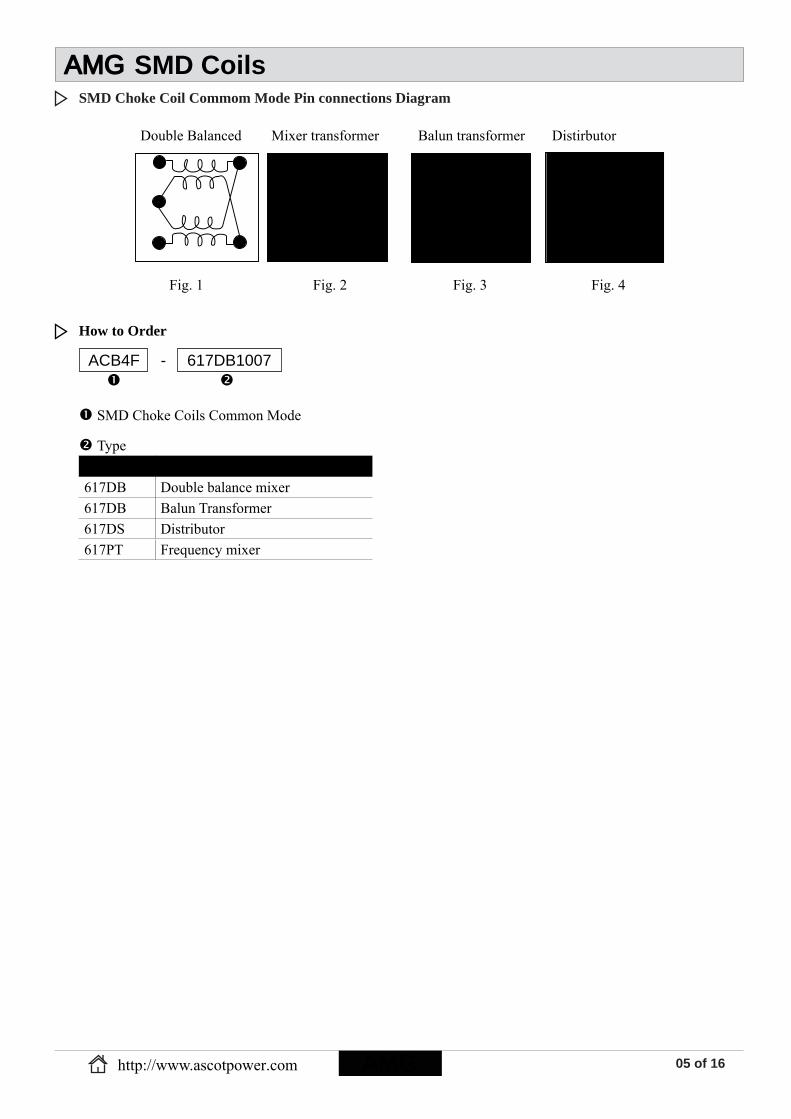
SMD Choke Coil Commom Mode Pin connections Diagram
Double Balanced Mixer transformer Balun transformer Distirbutor
4
61
2
34
6
3
2
1
4
6
3
2
11
2
3 4
6
Fig. 1 Fig. 2 Fig. 3 Fig. 4
Code Type617DB Double balance mixer617DB Balun Transformer617DS Distributor617PT Frequency mixer
How to Order
ACB4F - 617DB1007
SMD Choke Coils Common Mode
Type
AMGhttp://www.ascotpower.com
SMD CoilsAMG

06 of 16
Common Mode SMD Choke Coil FeaturesPair and triple wire coil for high stability high balance.
ApplicationsCommon mode fi lter, broad-band transformers;Impedance transformers, balun transformers, etc..
Common Mode SMD Choke Coil Confi g urations & Dimensions (unit: mm)
Common Mode SMD Choke Coils - A CB4FL Series
Type A±0.3 B(max) C(max) D±0.3 E(max) F±0.05 G±0.5 H±0.3 I J K LACB4FL 3.8 4.4 3.0 2.0 5.5 0.7 3.0 2.7 4.4 1.3 3.0 1.0
Note: Design as Customer’s Requested Specifi cations.
Common Mode SMD Choke Coil Electrical Characteristics for ACB4FL Series
Part Number Rated D.C. Current (Amp) (40°C) Figure For Two Lines
ACB4FL - 844CM1009 0.71 (Typ.) 1ACB4FL - 844CM1010 0.71 (Typ.) 1ACB4FL - 844CM1011 0.71 (Typ.) 1ACB4FL - 844CM1012 0.71 (Typ.) 1
For Three LinesACB4FL - 844CM1013 0.71 (Typ.) 2ACB4FL - 844CM1014 0.71 (Typ.) 2ACB4FL - 844CM1015 0.71 (Typ.) 2ACB4FL - 844CM1016 0.71 (Typ.) 2
J L
K
Land Pattern
C
G
HE
DA
B
F
Common Mode SMD Choke Coil Pin connections Diagram
3 Lines
0Ω
4 3
6 1
Fig. 150Ω
50ΩFig. 2
50Ω
4 3
6 125
2 Lines
http://www.ascotpower.comAMG
SMD CoilsAMG

07 of 16
Code Type844CM Two Lines844CM Three Lines
ACB4FL - 844CM1010
SMD Choke Coils Common Mode
Type
How to Order
AMGhttp://www.ascotpower.com
SMD CoilsAMG

08 of 16
Common Mode Choke Coil FeaturesPair wire coil for high stability.
ApplicationsDouble balance mixers, broad-band transformers;Impedance transformers, balun transformers, etc..
Common Mode Choke Coil Confi gurations & Dimensions (unit: mm)
Common Mode Choke Coil Electrical Characteristics for ACB5F Series
Common Mode Choke Coils - A CB5F Series
Continued on the following page.
Type A(max) B(max) C(max) D±0.5 E±0.05 F G H IACB5F 6.9 6.9 4.7 4.0 0.6 5.5 1.3 4.0 1.0
Note: Design as Customer’s Requested Specifi cations.
Part Number Winding Turns Operating Freq. Ranges (MHz) Insertion Loss (dB) Figure
Double balanced mixerACB5F - 458DB1012 1 50 ~ 400 10(max) 1ACB5F - 458DB1013 2 10 ~ 1.0GHz 6(max) 1ACB5F - 458DB1003 3 8 ~ 800 3.5(max) 1ACB5F - 458DB1008 4 6 ~ 600 2.5(max) 1ACB5F - 458DB1011 5 5 ~ 500 2(max) 1ACB5F - 458DB1005 2 400 ~ 1.3GHz 4(max) 1
DistributorACB5F - 458DS1014 - 20 ~ 600 In to Out-1,2
4.5dB(max) Out-1 to Out-2 (Isolation)
10dB(min)
3
Directional couplerACB5F - 458PS1015 4 6 ~ 600 In to Out-1 1.3dB(max)
In to Out-2 11dB-14dB4
ACB5F - 458PS1006 5 6 ~ 600 In to Out-1 0.9dB(max) In to Out-2 13dB-16dB
4
ACB5F - 458PS1007 6 6 ~ 600 In to Out-1 0.8dB(max) In to Out-2 15dB-17dB
4
A
B
C
D
EG
F
Land Pattern
I
H
http://www.ascotpower.comAMGAMG
SMD CoilsAMG
09 of 16
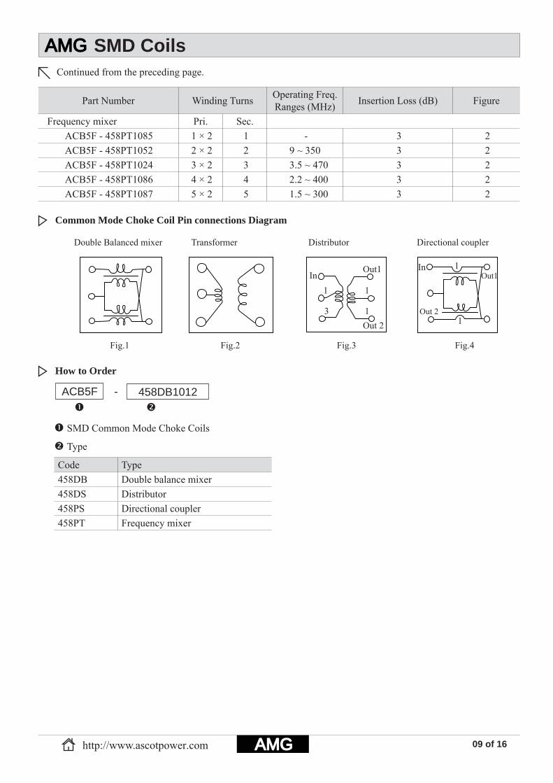
Common Mode Choke Coil Pin connections Diagram
Continued from the preceding page.
Code Type458DB Double balance mixer458DS Distributor458PS Directional coupler458PT Frequency mixer
How to Order
ACB5F -
SMD Common Mode Choke Coils
458DB1012
Type
Part Number Winding Turns Operating Freq. Ranges (MHz) Insertion Loss (dB) Figure
Frequency mixer Pri. Sec. ACB5F - 458PT1085 1 × 2 1 - 3 2ACB5F - 458PT1052 2 × 2 2 9 ~ 350 3 2ACB5F - 458PT1024 3 × 2 3 3.5 ~ 470 3 2ACB5F - 458PT1086 4 × 2 4 2.2 ~ 400 3 2ACB5F - 458PT1087 5 × 2 5 1.5 ~ 300 3 2
Double Balanced mixer Transformer Distributor Directional coupler
Fig.1 Fig.2 Fig.3 Fig.4
InOut1
Out 2
1
3
1
1
In
Out 2
Out11
1
http://www.ascotpower.com AMG
SMD CoilsAMG

10 of 16
SMD Common Mode Choke Coil FeaturesPair wire coil for high stability.
ApplicationsDouble balance mixers, broad-band transformers;Impedance transformers, balun transformers, etc..
SMD Common Mode Choke Coil Electrical Characteristics for ACB5FL Series
SMD Common Mode Choke Coils - A CB5FL Series
Continued on the following page.
Type A±0.3 B(max) C(max) D±0.5 E(max) F±0.05 G H I JACB5FL 3.8 6.9 3.9 4.0 6.9 0.6 5.5 1.3 4.0 1.0
Note: Design as Customer’s Requested Specifi cations.
A
B
C
D
FH
G
Land Pattern
J
I
E
Part Number Winding Turns Operating Freq. Ranges (MHz)
Insertion Loss (dB) Figure
Double balanced mixerACB5FL - 616DB1003 2 30 ~ 850 3 1ACB5FL - 616DB1004 3 6.5 ~ 1000 3 1ACB5FL - 616DB1007 4 3.5 ~ 1600 3 1ACB5FL - 616DB1008 5 2.5 ~ 1500 3 1
Frequency mixerACB5FL - 616PT1027 1 - 3 2ACB5FL - 616PT1028 2 8 ~ 550 3 2ACB5FL - 616PT1029 3 3.5 ~ 500 3 2ACB5FL - 616PT1030 4 2 ~ 370 3 2ACB5FL - 616PT1037 1 - 3 2ACB5FL - 616PT1038 2 500 ~ 850 3 2ACB5FL - 616PT1039 3 240 ~ 500 3 2ACB5FL - 616PT1040 4 85 ~ 380 3 2
Balun transformerACB5FL - 616DB1048 1.5 5.5 ~ 850 3 3ACB5FL - 616DB1049 2.5 2.5 ~ 2000 3 3ACB5FL - 616DB1050 3.5 1.2 ~ 1700 3 3
SMD Common Mode Choke Coil Confi gurations & Dimensions (unit: mm)
http://www.ascotpower.comAMG
SMD CoilsAMG
11 of 16
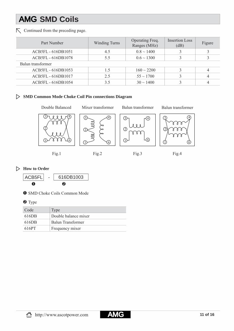
SMD Common Mode Choke Coil Pin connections Diagram
Continued from the preceding page.
Code Type616DB Double balance mixer616DB Balun Transformer616PT Frequency mixer
How to Order
ACB5FL -
SMD Choke Coils Common Mode
616DB1003
Type
Part Number Winding Turns Operating Freq. Ranges (MHz)
Insertion Loss (dB) Figure
ACB5FL - 616DB1051 4.5 0.8 ~ 1400 3 3ACB5FL - 616DB1078 5.5 0.6 ~ 1300 3 3
Balun transformerACB5FL - 616DB1053 1.5 160 ~ 2200 3 4ACB5FL - 616DB1017 2.5 55 ~ 1700 3 4ACB5FL - 616DB1054 3.5 30 ~ 1400 3 4
3
2
1 6
443
2
61
2
1
3 4
61
2
3 4
6
Double Balanced Mixer transformer Balun transformer Balun transformer
Fig.1 Fig.2 Fig.3 Fig.4
http://www.ascotpower.com AMG
SMD CoilsAMG

12 of 16
RFID Transponder Coil Features High Q value. Low profi le with an extended length.RFID Transponder Coil Applications
Car remote control key.
RFID Transponder Coil Electrical Characteristics for AC4380I Series
RFID Transponder Coils -A C4308I Series
Type A B C D E F G HAC4308I 11.43 3.15 2.74 1.01 0.51 2.79 1.78 8.46
Note: Design as Customer’s Requested Specifi cations.
RFID Transponder Coil Confi gurations & Dimensions (unit: mm)
Part Number Inductance (mH) Q (min) Test Freq.
(KHz) SRF (KHz)(min) DCR (Ω)(max)
AC4308I - 401J 0.40 15 125 4500 7.4AC4308I - 901J 0.90 15 125 4000 22AC4308I - 112J 1.08 15 125 4000 25AC4308I - 202J 1.97 17 125 2400 34AC4308I - 242J 2.38 17 125 2200 39AC4308I - 332J 3.30 17 125 1800 51AC4308I - 412J 4.15 17 125 1700 74AC4308I - 492J 4.90 17 125 1300 96AC4308I - 682J 6.80 17 125 1000 112AC4308I - 712J 7.10 17 125 1000 115AC4308I - 812J 8.10 17 125 960 123
Note: Test Freq.: 125KHz / 0.25V. Operating Temp.: -40°C+85°C.
B
A
AC
-XX
X
Top View E D
CF
Land Pattern
G
H
AC4308I - 401
Coils RFID Transponder
Inductance
J
ToleranceCode ToleranceJ 5% K 10%M 20%
How to Order
http://www.ascotpower.comAMG
SMD CoilsAMG

13 of 16
Tape and Reel Specifi cations for Surface Mount (Unit: mm)
Tape and Reel Specifi cations for Surface Mount
AMG Part No.Piece / Reel Reel Dimensions Tape Dimensions178 330 A B C W A0 B0 K0 P P0 P2 W t
Multilayer Chip InductorsACMF100505 10,000 - 178 62 13 8.5 0.65 1.15 0.80 2 4 2 8 0.23ACMF/I160808 4,000 - 178 62 13 8.5 1.01 1.80 1.05 4 4 2 8 0.23ACMF/I201209 4,000 - 178 62 13 8.5 1.42 2.24 1.04 4 4 2 8 0.23ACMI201212 2,000 - 178 62 13 8.5 1.50 2.30 1.60 4 4 2 8 0.23ACMI321611 3,000 - 178 62 13 8.5 1.88 3.50 1.27 4 4 2 8 0.23
Multilayer Chip Beads for Large CurrentACMB100505 10,000 - 178 62 13 8.5 0.65 1.15 0.80 2 4 2 8 0.23ACMA/B160808 4,000 - 178 62 13 8.5 1.01 1.80 1.05 4 4 2 8 0.23ACMA/B201209 4,000 - 178 62 13 8.5 1.42 2.24 1.04 4 4 2 8 0.23ACMA/B321611 3,000 - 178 62 13 8.5 1.88 3.50 1.27 4 4 2 8 0.23ACMB321616 2,000 - 178 62 13 8.5 1.88 3.61 1.78 4 4 2 8 0.23ACMA/B322513 2,000 - 178 62 13 8.5 2.69 3.48 1.43 4 4 2 8 0.23ACMA/B451616 2,000 - 178 62 13 12.5 1.93 4.95 1.93 4 4 2 12 0.23ACMA/B453215 1,000 - 178 62 13 12.5 3.66 4.95 1.83 8 4 2 12 0.23
RFID Transponder CoilsAC4308I - 3,000 330 100 13 24.5 3.30 11.55 2.70 8 4 2 24 0.35
Common Mode Choke CoilsACB4F - 2,000 330 100 13 12.5 4.40 5.40 3.50 8 4 2 12 0.4ACB4FL - 2,000 330 100 13 12.5 4.40 5.40 3.20 8 4 2 12 0.4ACB5F - 1,000 330 100 13 16.5 6.40 6.90 4.60 12 4 2 16 0.4ACB5FL - 1,500 330 100 13 16.5 6.40 6.90 3.95 12 4 2 16 0.4
Air Core Inductors (Flat Top Air Core Inductors)ACAM0603 - 4,000 330 100 13 12.5 1.55 2.00 2.00 8 4 2 12 0.3ACAM0805 - 4,000 330 100 13 12.5 1.55 2.50 2.00 8 4 2 12 0.3ACAM1008 - 4,000 330 100 13 12.5 1.55 3.20 2.00 8 4 2 12 0.3ACAM2215 - 4,000 330 100 13 12.5 1.60 2.40 1.50 8 4 2 12 0.3ACAM4015 - 4,000 330 100 13 12.5 1.60 4.20 1.50 8 4 2 12 0.3ACAM3730 - 2,500 330 100 13 12.5 3.50 4.00 3.20 8 4 2 12 0.3ACAM7030 - 2,000 330 100 13 16.5 3.50 7.00 3.20 8 4 2 16 0.3ACAM1812 - 2,000 330 100 13 16.5 5.45 6.80 4.00 8 4 2 16 0.3ACAM132 - 1,000 330 100 13 16.5 4.70 9.10 4.90 8 4 2 16 0.3
+
+ + + + + + + + + + +
1.Reel Dimensions
C w
AB
2.Tape Dimensions
t P0 P2
B0
K0A0
P
W
Feed direction
http://www.ascotpower.com AMG
AMG Tape and Reel Specifi cations

14 of 16
+
+ + + + + + + + + + +
1.Reel Dimensions
C w
AB
2.Tape Dimensions
t P0 P2
B0
K0A0
P
W
Feed direction
AMG Part No.
Piece / Reel Reel Dimensions Tape Dimensions178 330 A B C W A0 B0 K0 P P0 P2 W t
Shielded Power Inductors - TCD seriesACD62LCB - 2,000 330 100 13 12.5 6.20 6.20 2.10 8 4 2 12 0.3ACD62CB - 2,000 330 100 13 12.5 6.30 6.30 2.60 8 4 2 12 0.3ACD63LCB - 2,000 330 100 13 12.5 6.20 6.20 3.10 8 4 2 12 0.4ACD63CB - 1,500 330 100 13 12.5 6.35 6.35 3.55 12 4 2 12 0.4ACD73C - 1,000 330 100 13 16.5 7.60 7.60 4.00 12 4 2 16 0.3ACD75C - 1,000 330 100 13 16.5 7.60 7.60 5.40 12 4 2 16 0.4ACD1014C - 2,000 330 100 13 24.5 10.50 10.50 2.00 16 4 2 24 0.4ACD4009C - 5,000 330 100 13 12.5 5.15 5.15 1.5 8 4 2 12 0.4ACD4011C - 5,000 330 100 13 12.5 5.15 5.15 1.5 8 4 2 12 0.4ACD4014C - 5,000 330 100 13 12.5 5.15 5.15 1.5 8 4 2 12 0.4ACD7014C - 2,500 330 100 13 16.5 7.40 7.40 2.00 12 4 2 16 0.4ACD7026C - 1,500 330 100 13 16.5 7.40 7.40 3.00 12 4 2 16 0.4
Shielded Power Inductors - RB seriesACR63B - 2,000 330 100 13 12.5 5.70 6.30 3.60 8 4 2 12 0.3ACR74B - 1,000 330 100 13 16.5 7.20 8.00 5.60 12 4 2 16 0.35ACR105B - 500 330 100 13 24.5 9.20 10.20 5.90 12 4 2 24 0.4
Shielded Power Inductors - RH seriesACRH62B - 1,500 330 100 13 16.5 6.55 7.00 3.20 12 4 2 16 0.4ACRH64B - 1,000 330 100 13 16.5 6.55 7.00 5.20 12 4 2 16 0.4ACRH73 - 1,000 330 100 13 16.5 7.60 7.60 4.00 12 4 2 16 0.3ACRH74 - 1,000 330 100 13 16.5 7.60 7.60 5.40 12 4 2 16 0.4
ACRH124 - 500 330 100 13 24.5 12.55 12.55 5.05 16 4 2 24 0.35ACRH125 - 500 330 100 13 24.5 12.55 12.55 6.40 16 4 2 24 0.35ACRH127 - 500 330 100 13 24.5 12.55 12.55 8.10 16 4 2 24 0.35ACRH124B - 500 330 100 13 24.5 12.55 12.55 5.05 16 4 2 24 0.35ACRH125B - 500 330 100 13 24.5 12.55 12.55 6.40 16 4 2 24 0.35ACRH127B - 500 330 100 13 24.5 12.55 12.55 8.10 16 4 2 24 0.35ACRH103R - 1,000 330 100 13 24.5 10.30 10.50 3.10 16 4 2 24 0.35ACRH104R - 1,000 330 100 13 24.5 10.30 10.50 4.10 16 4 2 24 0.35ACRH105R - 500 330 100 13 24.5 10.30 10.50 5.10 16 4 2 24 0.35ACRH8D43 - 500 330 100 13 16.5 9.90 8.30 4.50 16 4 2 16 0.4
http://www.ascotpower.comAMG
AMG Tape and Reel Specifi cations

15 of 16
AMG Part No.Piece / Reel Reel Dimensions Tape Dimensions
178 330 A B C W A0 B0 K0 P P0 P2 W tShielded Power Inductors - RH series
ACRH2D18A - 3,000 330 100 13 12.5 3.40 3.40 2.10 8 4 2 12 0.35ACRH3D16A - 3,000 330 100 13 12.5 4.10 4.10 2.10 8 4 2 12 0.35ACRH4D18 - 2,000 330 100 13 12.5 5.10 5.10 2.10 8 4 2 12 0.3ACRH4D28 - 2,000 330 100 13 12.5 5.10 5.10 3.10 8 4 2 12 0.3ACRH5D18 - 2,000 330 100 13 12.5 6.10 6.10 2.10 8 4 2 12 0.3ACRH5D28 - 2,000 330 100 13 12.5 6.10 6.10 3.10 8 4 2 12 0.3ACRH6D28 - 1,000 330 100 13 16.5 7.60 7.60 3.10 12 4 2 16 0.35ACRH6D38 - 1,000 330 100 13 16.5 7.60 7.60 4.10 12 4 2 16 0.35ACRH8D28 - 1,000 330 100 13 16.5 9.90 8.30 3.00 16 4 2 16 0.4ACRH8D43 - 500 330 100 13 16.5 9.90 8.30 4.50 16 4 2 16 0.4
Shielded Power Inductors - DS seriesACDS104C2 - 500 330 100 13 24.5 10.30 10.50 5.10 16 4 2 24 0.35ACDS106C2 - 500 330 100 13 24.5 10.60 10.70 7.00 16 4 2 24 0.5ACDS126C2 - 500 330 100 13 24.5 12.55 12.55 8.10 16 4 2 24 0.35
Shielded Power Inductors - SLF seriesACSLF6028 - 1,500 330 100 13 12.5 6.35 6.35 3.55 12 4 2 12 0.4ACSLF10145 - 500 330 100 13 24.5 10.30 10.50 5.10 16 4 2 24 0.4ACSLF12555 - 500 330 100 13 24.5 13.05 13.05 6.20 16 4 2 24 0.4ACSLF12565 - 500 330 100 13 24.5 13.05 13.05 7.20 16 4 2 24 0.4ACSLF12575 - 500 330 100 13 24.5 13.05 13.05 8.20 16 4 2 24 0.4
Shielded Power Inductors - DC seriesAC1608DC - 2,500 330 100 13 16.5 4.25 6.50 3.00 8 4 2 16 0.35AC3316DC - 1,000 330 100 13 24.5 9.55 13.10 5.40 12 4 2 24 0.35AC5022DC - 250 330 100 13 32.5 15.40 18.80 7.50 20 4 2 32 0.4
SMT Unshielded Power Inductors - UD SeriesACD4006 1,000 - 178 62 13 12.5 5.80 6.30 1.30 8 4 2 12 0.4ACD4008 1,000 - 178 100 13 12.5 5.80 6.30 1.30 8 4 2 12 0.4ACD4011 1,000 - 178 100 13 12.5 4.50 5.60 1.55 8 4 2 12 0.4ACD4013 1,000 - 178 100 13 12.5 4.50 5.60 1.55 8 4 2 12 0.4ACD5011 - 4,500 330 100 13 12.5 5.90 7.50 1.70 8 4 2 12 0.4ACD5013 - 4,500 330 100 13 12.5 5.90 7.50 1.70 8 4 2 12 0.4
+
+ + + + + + + + + + +
1.Reel Dimensions
C w
AB
2.Tape Dimensions
t P0 P2
B0
K0A0
P
W
Feed direction
http://www.ascotpower.com AMGAMG
AMG Tape and Reel Specifi cations

AMG Part No.Piece / Reel Reel Dimensions Tape Dimensions178 330 A B C W A0 B0 K0 P P0 P2 W t
SMT Unshielded Power Inductors - UTC seriesAC32 2,000 - 178 62 13 8.5 3.12 3.84 2.24 4 4 2 8 0.3AC43 - 1,500 330 100 13 12.5 4.20 4.60 3.60 8 4 2 12 0.3AC52 - 2,500 330 100 13 12.5 5.50 6.00 2.70 8 4 2 12 0.3AC53 - 1,500 330 100 13 12.5 5.60 6.20 3.30 8 4 2 12 0.4AC54 - 1,500 330 100 13 12.5 5.60 6.20 4.70 8 4 2 12 0.3AC73 - 1,000 330 100 13 16.5 7.30 8.00 3.80 12 4 2 16 0.3AC75 - 1,000 330 100 13 16.5 7.20 8.00 5.60 12 4 2 16 0.35AC104 - 500 330 100 13 24.5 9.60 10.30 4.20 12 4 2 24 0.35AC105 - 500 330 100 13 24.5 9.60 10.30 5.80 12 4 2 24 0.4
ACD73F - 1,000 330 100 13 16.5 7.60 7.60 4.00 12 4 2 16 0.3ACD75F - 1,000 330 100 13 16.5 7.60 7.60 5.40 12 4 2 16 0.4AC1608DF - 2,500 330 100 13 16.5 4.25 6.50 3.00 8 4 2 16 0.35AC3308DF - 1,000 330 100 13 24.5 9.70 13.25 3.30 12 4 2 24 0.35AC3316DF - 1,000 330 100 13 24.5 9.55 13.10 5.40 12 4 2 24 0.35AC3340DF - 225 330 100 13 32.5 9.70 13.40 11.50 20 4 2 32 0.5AC5022DF - 250 330 100 13 32.5 15.40 18.80 7.50 20 4 2 32 0.4AC1813DHP - 1,000 330 100 13 16.5 6.30 9.15 4.90 12 4 2 16 0.4AC3316DHP - 1,000 330 100 13 24.5 9.55 13.10 5.40 12 4 2 24 0.35AC5022DHP - 250 330 100 13 32.5 16.00 21.90 7.65 20 4 2 32 0.5Backlight Power InductorsAC1608DBL - 2,500 330 100 13 16.5 4.25 6.50 3.00 8 4 2 16 0.35Toroidal Power InductorsACTX-2P - 500 330 100 13 24.5 10.25 10.25 5.50 16 4 2 24 0.4ACTX-4P - 500 330 100 13 24.5 12.70 12.70 7.00 16 4 2 24 0.4AC302 - 500 330 100 13 24.5 8.95 10.25 6.90 16 4 2 24 0.4AC502 - 250 330 100 13 32.5 13.80 16.50 10.20 24 4 2 32 0.4AC302A - 500 330 100 13 24.5 8.95 10.25 6.90 16 4 2 24 0.4AC502A - 250 330 100 13 32.5 13.80 16.50 10.20 24 4 2 32 0.4AC0718 - 3,000 330 100 13 16.5 5.30 7.90 2.20 8 4 2 16 0.4
16 of 16
+
+ + + + + + + + + + +
1.Reel Dimensions
C w
AB
2.Tape Dimensions
t P0 P2
B0
K0A0
P
W
Feed direction
http://www.ascotpower.comAMG
AMG Tape and Reel Specifi cations