Embed Size (px)
Citation preview
Teknisk chef Ledn Marktele 100 017307 2010-03-01 Sida 1 (10)
Rohde&Schwarz M3SR (XT4410A)
FÖRSVARETS MATERIELVERK TEKNISK ORDER ALLMÄN AF SAMBAND
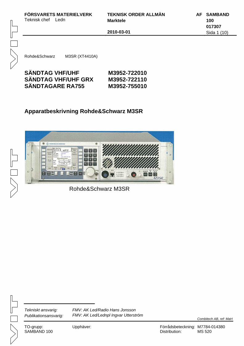
SÄNDTAG VHF/UHF M3952-722010 SÄNDTAG VHF/UHF GRX M3952-722110 SÄNDTAGARE RA755 M3952-755010 Apparatbeskrivning Rohde&Schwarz M3SR
Rohde&Schwarz M3SR
Tekniskt ansvarig: FMV: AK Led/Radio Hans Jonsson Publikationsansvarig: FMV: AK Led/Lednpl Ingvar Utterström
Combitech AB, ref: MaH
TO-grupp: Upphäver: Förrådsbeteckning: M7784-014380 SAMBAND 100 Distribution: MS 520
FÖRSVARETS MATERIELVERK TEKNISK ORDER ALLMÄN AF SAMBAND Marktele 100 017307 2010-03-01 Sida 2
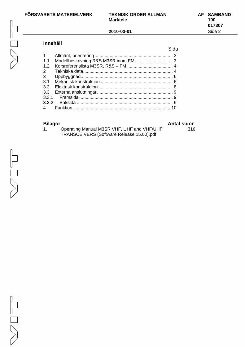
Innehåll Sida 1 Allmänt, orientering .............................................................. 3 1.1 Modellbeskrivning R&S M3SR inom FM.............................. 3 1.2 Korsreferenslista M3SR, R&S – FM .................................... 4 2 Tekniska data....................................................................... 4 3 Uppbyggnad......................................................................... 6 3.1 Mekanisk konstruktion ......................................................... 6 3.2 Elektrisk konstruktion ........................................................... 8 3.3 Externa anslutningar ............................................................ 9 3.3.1 Framsida .......................................................................... 9 3.3.2 Baksida ............................................................................ 9 4 Funktion ............................................................................. 10
Bilagor Antal sidor 1. Operating Manual M3SR VHF, UHF and VHF/UHF
TRANSCEIVERS (Software Release 15.00).pdf 316
FÖRSVARETS MATERIELVERK TEKNISK ORDER ALLMÄN AF SAMBAND Marktele 100 017307 2010-03-01 Sida 3
1 Allmänt, orientering
Rohde & Schwarz M3SR (Multiband, Multimode and Multirole Surface Radio) är en flexible sändtagare för militära likväl som för civila tillämpningar.
Sändtagaren är designad som en avancerad, pålitlig och dynamisk kommunikationsplattform för att möta kraven för fasta som mobila kommunikationslösningar.
Sändtagaren kan användas för sändning och mottagning av analogt tal, digitalt tal och data för de mest vanliga modulationstyperna (AM, FM) konfigurerat antigen som narrowband eller wideband. Sändningen kan ske, med fasta frekvenser, på VHF- och/eller UHF-bandet beroende på modell.
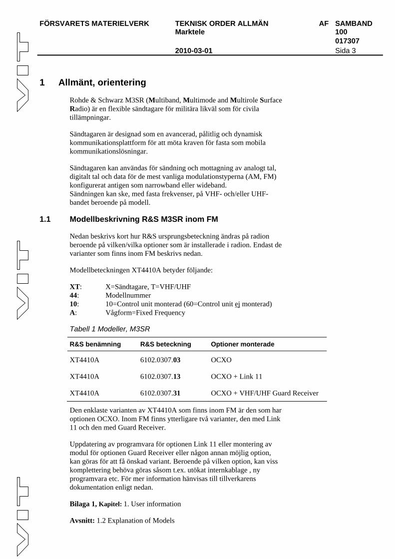
1.1 Modellbeskrivning R&S M3SR inom FM
Nedan beskrivs kort hur R&S ursprungsbeteckning ändras på radion beroende på vilken/vilka optioner som är installerade i radion. Endast de varianter som finns inom FM beskrivs nedan.
Modellbeteckningen XT4410A betyder följande:
XT: X=Sändtagare, T=VHF/UHF 44: Modellnummer 10: 10=Control unit monterad (60=Control unit ej monterad) A: Vågform=Fixed Frequency
Tabell 1 Modeller, M3SR
R&S benämning R&S beteckning Optioner monterade
XT4410A 6102.0307.03 OCXO
XT4410A 6102.0307.13 OCXO + Link 11
XT4410A 6102.0307.31 OCXO + VHF/UHF Guard Receiver
Den enklaste varianten av XT4410A som finns inom FM är den som har optionen OCXO. Inom FM finns ytterligare två varianter, den med Link 11 och den med Guard Receiver.
Uppdatering av programvara för optionen Link 11 eller montering av modul för optionen Guard Receiver eller någon annan möjlig option, kan göras för att få önskad variant. Beroende på vilken option, kan viss komplettering behöva göras såsom t.ex. utökat internkablage , ny programvara etc. För mer information hänvisas till tillverkarens dokumentation enligt nedan.
Bilaga 1, Kapitel: 1. User information
Avsnitt: 1.2 Explanation of Models
FÖRSVARETS MATERIELVERK TEKNISK ORDER ALLMÄN AF SAMBAND Marktele 100 017307 2010-03-01 Sida 4
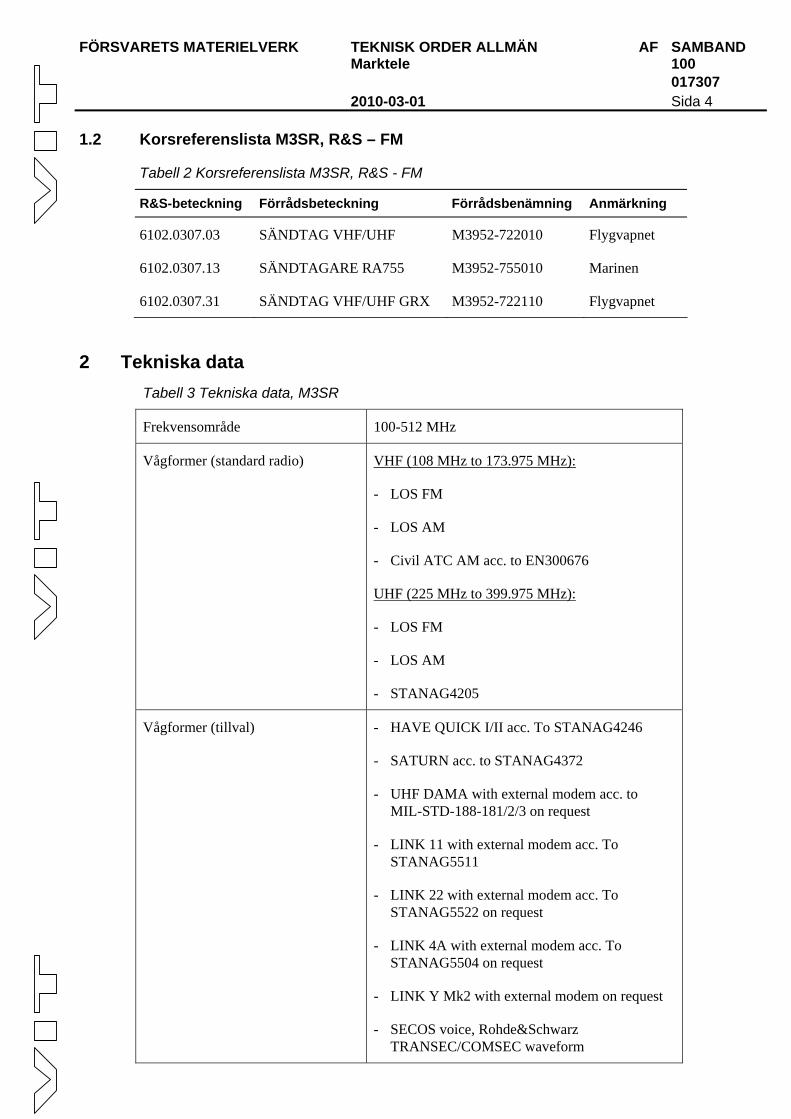
1.2 Korsreferenslista M3SR, R&S – FM
Tabell 2 Korsreferenslista M3SR, R&S - FM
R&S-beteckning Förrådsbeteckning Förrådsbenämning Anmärkning
6102.0307.03 SÄNDTAG VHF/UHF M3952-722010 Flygvapnet
6102.0307.13 SÄNDTAGARE RA755 M3952-755010 Marinen
6102.0307.31 SÄNDTAG VHF/UHF GRX M3952-722110 Flygvapnet
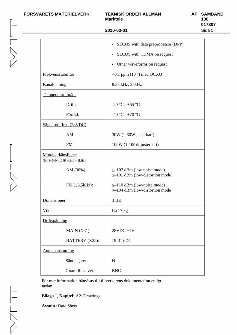
2 Tekniska data Tabell 3 Tekniska data, M3SR
Frekvensområde 100-512 MHz
Vågformer (standard radio) VHF (108 MHz to 173.975 MHz):
- LOS FM
- LOS AM
- Civil ATC AM acc. to EN300676
UHF (225 MHz to 399.975 MHz):
- LOS FM
- LOS AM
- STANAG4205
Vågformer (tillval) - HAVE QUICK I/II acc. To STANAG4246
- SATURN acc. to STANAG4372
- UHF DAMA with external modem acc. to MIL-STD-188-181/2/3 on request
- LINK 11 with external modem acc. To STANAG5511
- LINK 22 with external modem acc. To STANAG5522 on request
- LINK 4A with external modem acc. To STANAG5504 on request
- LINK Y Mk2 with external modem on request
- SECOS voice, Rohde&Schwarz TRANSEC/COMSEC waveform
FÖRSVARETS MATERIELVERK TEKNISK ORDER ALLMÄN AF SAMBAND Marktele 100 017307 2010-03-01 Sida 5
- SECOS with data preprocessor (DPP)
- SECOS with TDMA on request
- Other waveforms on request
Frekvensstabilitet <0.1 ppm (10–7) med OCXO
Kanaldelning 8.33 kHz, 25kHz
Temperaturområde
Drift:
Förråd:
-20 °C - +55 °C
-40 °C - +70 °C
Sändaruteffekt (28VDC)
AM:
FM:
30W (1-30W justerbart)
100W (1-100W justerbart)
Mottagarkänslighet (för S+N/N=10dB och fm= 1kHz)
AM (30%):
≤–107 dBm (low-noise mode) ≤–101 dBm (low-distortion mode)
FM (±3,5kHz): ≤–110 dBm (low-noise mode) ≤–104 dBm (low-distortion mode)
Dimensioner 3 HE
Vikt Ca 17 kg
Driftspänning
MAIN (X31):
BATTERY (X32):
28VDC ±1V
19-31VDC
Antennanslutning
Sändtagare:
Guard Receiver:
N
BNC
För mer information hänvisas till tillverkarens dokumentation enligt nedan.
Bilaga 1, Kapitel: A2. Drawings
Avsnitt: Data Sheet
FÖRSVARETS MATERIELVERK TEKNISK ORDER ALLMÄN AF SAMBAND Marktele 100 017307 2010-03-01 Sida 6
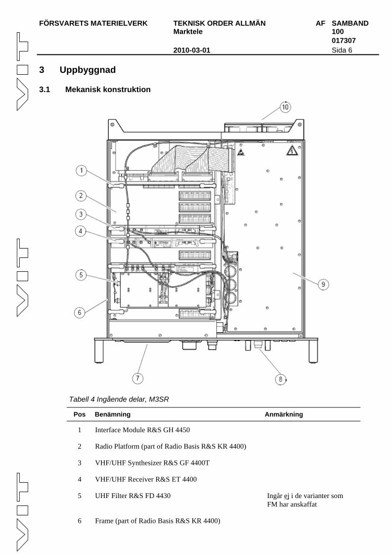
3 Uppbyggnad
3.1 Mekanisk konstruktion
Tabell 4 Ingående delar, M3SR
Pos Benämning Anmärkning
1 Interface Module R&S GH 4450
2 Radio Platform (part of Radio Basis R&S KR 4400)
3 VHF/UHF Synthesizer R&S GF 4400T
4 VHF/UHF Receiver R&S ET 4400
5 UHF Filter R&S FD 4430 Ingår ej i de varianter som FM har anskaffat
6 Frame (part of Radio Basis R&S KR 4400)
FÖRSVARETS MATERIELVERK TEKNISK ORDER ALLMÄN AF SAMBAND Marktele 100 017307 2010-03-01 Sida 7
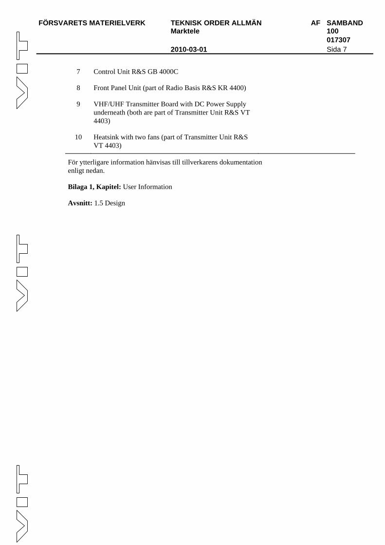
7 Control Unit R&S GB 4000C
8 Front Panel Unit (part of Radio Basis R&S KR 4400)
9 VHF/UHF Transmitter Board with DC Power Supply underneath (both are part of Transmitter Unit R&S VT 4403)
10 Heatsink with two fans (part of Transmitter Unit R&S VT 4403)
För ytterligare information hänvisas till tillverkarens dokumentation enligt nedan.
Bilaga 1, Kapitel: User Information
Avsnitt: 1.5 Design
FÖRSVARETS MATERIELVERK TEKNISK ORDER ALLMÄN AF SAMBAND Marktele 100 017307 2010-03-01 Sida 8
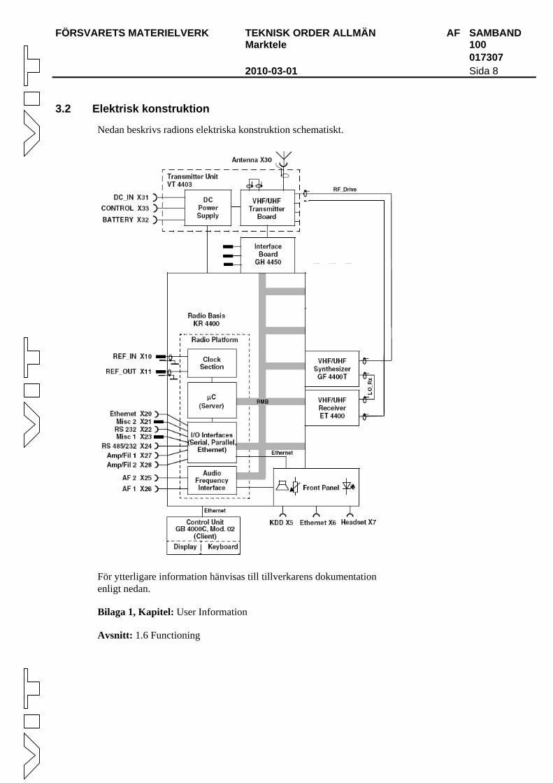
3.2 Elektrisk konstruktion
Nedan beskrivs radions elektriska konstruktion schematiskt.
För ytterligare information hänvisas till tillverkarens dokumentation enligt nedan.
Bilaga 1, Kapitel: User Information
Avsnitt: 1.6 Functioning
FÖRSVARETS MATERIELVERK TEKNISK ORDER ALLMÄN AF SAMBAND Marktele 100 017307 2010-03-01 Sida 9
3.3 Externa anslutningar
Nedan listas de externa anslutningar som finns på radion.
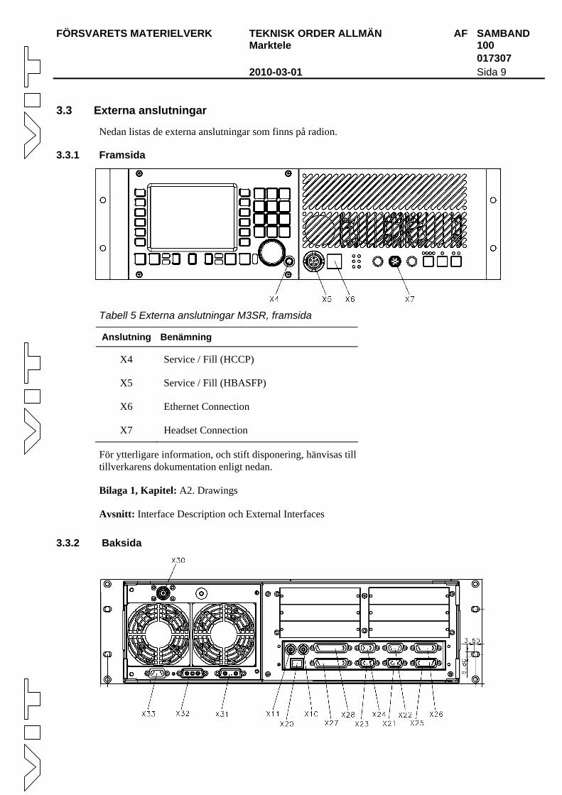
3.3.1 Framsida
Tabell 5 Externa anslutningar M3SR, framsida
Anslutning Benämning
X4 Service / Fill (HCCP)
X5 Service / Fill (HBASFP)
X6 Ethernet Connection
X7 Headset Connection
För ytterligare information, och stift disponering, hänvisas till tillverkarens dokumentation enligt nedan.
Bilaga 1, Kapitel: A2. Drawings
Avsnitt: Interface Description och External Interfaces
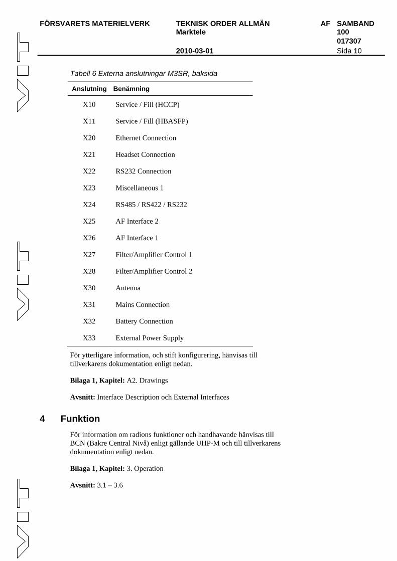
3.3.2 Baksida
FÖRSVARETS MATERIELVERK TEKNISK ORDER ALLMÄN AF SAMBAND Marktele 100 017307 2010-03-01 Sida 10
Tabell 6 Externa anslutningar M3SR, baksida
Anslutning Benämning
X10 Service / Fill (HCCP)
X11 Service / Fill (HBASFP)
X20 Ethernet Connection
X21 Headset Connection
X22 RS232 Connection
X23 Miscellaneous 1
X24 RS485 / RS422 / RS232
X25 AF Interface 2
X26 AF Interface 1
X27 Filter/Amplifier Control 1
X28 Filter/Amplifier Control 2
X30 Antenna
X31 Mains Connection
X32 Battery Connection
X33 External Power Supply
För ytterligare information, och stift konfigurering, hänvisas till tillverkarens dokumentation enligt nedan.
Bilaga 1, Kapitel: A2. Drawings
Avsnitt: Interface Description och External Interfaces
4 Funktion För information om radions funktioner och handhavande hänvisas till BCN (Bakre Central Nivå) enligt gällande UHP-M och till tillverkarens dokumentation enligt nedan.
Bilaga 1, Kapitel: 3. Operation
Avsnitt: 3.1 – 3.6
Bilaga 1 till TO AF SAMBAND 100 017307
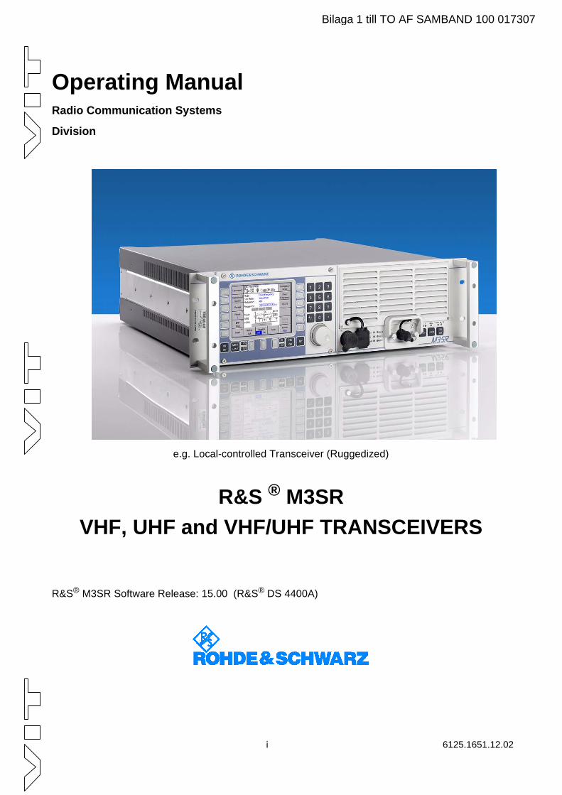
Operating ManualRadio Communication Systems
Division
e.g. Local-controlled Transceiver (Ruggedized)
R&S ® M3SRVHF, UHF and VHF/UHF TRANSCEIVERS
R&S® M3SR Software Release: 15.00 (R&S® DS 4400A)
i 6125.1651.12.02
Bilaga 1 till TO AF SAMBAND 100 017307
©2008
Copying of this document as well as any other utilization and communication of its content are only admissible with the permission of the originator or other authorized persons.
Any disregard will be prosecuted and is subject to restitution (UrhG, UWG, BGB). For the case a patent is issued or the design is officially registered all rights are reserved.
R&S® is a registered trademark of Rohde & Schwarz GmbH & Co. KG.
All other product names are trademarks of their respective owners.
ROHDE & SCHWARZ GmbH & Co. KG
Mühldorfstr. 15
D-81671 München
www.rohde-schwarz.com
Printed in the Federal Republic of Germany
Subject to change
Data without tolerances: order of magnitude only
0708
6125.1651.12.02 ii
1171.0200.11-02.00
DIN EN ISO 9001 : 2000DIN EN 9100 : 2003DIN EN ISO 14001 : 2004
DQS REG. NO 001954 QM UM
Certified Quality System
Sehr geehrter Kunde,Sie haben sich für den Kauf eines Rohde & Schwarz-Produktes entschie-den. Hiermit erhalten Sie ein nach modernsten Fertigungsmethoden hergestelltes Produkt. Es wurde nach den Regeln unseres Management-systems entwickelt, gefertigt und geprüft. Das Rohde & Schwarz Management-system ist zertifiziert nach:
DIN EN ISO 9001:2000DIN EN 9100:2003DIN EN ISO 14001:2004
Dear Customer,you have decided to buy a Rohde &Schwarz product. You are thus as-sured of receiving a product that is manufactured using the most modern methods available. This product was developed, manufactured and tested in compliance with our quality manage-ment system standards. The Rohde & Schwarz quality manage-ment system is certified according to:
DIN EN ISO 9001:2000DIN EN 9100:2003DIN EN ISO 14001:2004
Cher Client,vous avez choisi d‘acheter un produitRohde & Schwarz. Vous disposez donc d‘un produit fabriqué d‘après les méthodes les plus avancées. Le développement, la fabrication et les tests respectent nos normes de ges-tion qualité. Le système de gestion qualité de Rohde & Schwarz a été homologué conformément aux normes:
DIN EN ISO 9001:2000DIN EN 9100:2003DIN EN ISO 14001:2004
QUALITÄTSZERTIFIKAT CERTIFICATE OF QUALITY CERTIFICAT DE QUALITÉ
Bilaga 1 till TO AF SAMBAND 100 017307
1171.0200.42-02.00
12
12Address List
Headquarters, Plants and Subsidiaries
HeadquartersROHDE&SCHWARZ GmbH & Co. KGMühldorfstraße 15 · D-81671 MünchenP.O.Box 80 14 69 · D-81614 München
PlantsROHDE&SCHWARZ Messgerätebau GmbHRiedbachstraße 58 · D-87700 MemmingenP.O.Box 16 52 · D-87686 Memmingen
ROHDE&SCHWARZ GmbH & Co. KGWerk TeisnachKaikenrieder Straße 27 · D-94244 TeisnachP.O.Box 11 49 · D-94240 Teisnach
ROHDE&SCHWARZ závodVimperk, s.r.o.Location Spidrova 49CZ-38501 Vimperk
ROHDE&SCHWARZ GmbH & Co. KGDienstleistungszentrum KölnGraf-Zeppelin-Straße 18 · D-51147 KölnP.O.Box 98 02 60 · D-51130 Köln
SubsidiariesR&S BICK Mobilfunk GmbH Fritz-Hahne-Str. 7 · D-31848 Bad Münder P.O.Box 20 02 · D-31844 Bad Münder
ROHDE&SCHWARZ FTK GmbH Wendenschloßstraße 168, Haus 28 D-12557 Berlin
ROHDE&SCHWARZ SIT GmbHAm Studio 3D-12489 Berlin
R&S Systems GmbHGraf-Zeppelin-Straße 18D-51147 Köln
GEDIS GmbHSophienblatt 100D-24114 Kiel
HAMEG Instruments GmbHIndustriestraße 6D-63533 Mainhausen
Locations Worldwide
Please refer to our homepage: www.rohde-schwarz.com
Sales Locations Service Locations National Websites
Phone +49 (89) 41 29-0Fax +49 (89) 41 29-121 64
Phone +49 (83 31) 1 08-0+49 (83 31) 1 08-1124
Phone +49 (99 23) 8 50-0Fax +49 (99 23) 8 50-174
Phone +420 (388) 45 21 09Fax +420 (388) 45 21 13
Phone +49 (22 03) 49-0Fax +49 (22 03) 49 51-229
[email protected]@rohde-schwarz.com
Phone +49 (50 42) 9 98-0Fax +49 (50 42) 9 98-105
Phone +49 (30) 658 91-122Fax +49 (30) 655 50-221
Phone +49 (30) 658 84-0Fax +49 (30) 658 84-183
Phone +49 (22 03) 49-5 23 25Fax +49 (22 03) 49-5 23 36
Phone +49 (431) 600 51-0Fax +49 (431) 600 [email protected]
Phone +49 (61 82) 800-0Fax +49 (61 82) 800-100
Bilaga 1 till TO AF SAMBAND 100 017307

1171.0200.22-02.00
Customer Support Technical support where and when you need it For quick, expert help with any Rohde & Schwarz equipment, contact one of our Customer Support Centers. A team of highly qualified engineers provides telephone support and will work with you to find a solution to your query on any aspect of the operation, programming or applications of Rohde & Schwarz equipment. Up-to-date information and upgrades To keep your instrument up-to-date and to be informed about new application notes related to your instrument, please send an e-mail to the Customer Support Center stating your instrument and your wish. We will take care that you will get the right information. USA & Canada Monday to Friday (except US public holidays)
8:00 AM 8:00 PM Eastern Standard Time (EST) Tel. from USA 888-test-rsa (888-837-8772) (opt 2)
From outside USA +1 410 910 7800 (opt 2) Fax +1 410 910 7801
E-mail [email protected] East Asia Monday to Friday (except Singaporean public holidays)
8:30 AM 6:00 PM Singapore Time (SGT) Tel. +65 6 513 0488
Fax +65 6 846 1090
E-mail [email protected] Rest of the World Monday to Friday (except German public holidays)
08:00 17:00 Central European Time (CET) Tel. from Europe +49 (0) 180 512 42 42*
From outside Europe +49 89 4129 13776 Fax +49 (0) 89 41 29 637 78
E-mail [email protected] * 0.14 /Min within the German fixed-line telephone network, varying prices for the mobile telephone network and in different countries.
Bilaga 1 till TO AF SAMBAND 100 017307

Grouped Safety Messages Make sure to read through and observe the following safety instructions!
All plants and locations of the Rohde & Schwarz group of companies make every effort to keep the safety standard of our products up to date and to offer our customers the highest possible degree of safety. Our products and the auxiliary equipment required for them are designed and tested in accordance with the relevant safety standards. Compliance with these standards is continuously monitored by our quality assurance system. The product described here has been designed and tested in accordance with the EC Certificate of Conformity and has left the manufacturer’s plant in a condition fully complying with safety standards. To maintain this condition and to ensure safe operation, observe all instructions and warnings provided in this manual. If you have any questions regarding these safety instructions, the Rohde & Schwarz group of companies will be happy to answer them.
Furthermore, it is your responsibility to use the product in an appropriate manner. This product is designed for use solely in industrial and laboratory environments or, if expressly permitted, also in the field and must not be used in any way that may cause personal injury or property damage. You are responsible if the product is used for an intention other than its designated purpose or in disregard of the manufacturer's instructions. The manufacturer shall assume no responsibility for such use of the product.
The product is used for its designated purpose if it is used in accordance with its product documentation and within its performance limits (see data sheet, documentation, the following safety instructions). Using the product requires technical skills and a basic knowledge of English. It is therefore essential that only skilled and specialized staff or thoroughly trained personnel with the required skills be allowed to use the product. If personal safety gear is required for using Rohde & Schwarz products, this will be indicated at the appropriate place in the product documentation. Keep the basic safety instructions and the product documentation in a safe place and pass them on to the subsequent users.
Symbols and safety labels
Observe product
documentation
Weight indication for units >18 kg
Danger of electric shock
Warning! Hot
surface PE terminal Ground Ground
terminal
Attention! Electrostatic
sensitive devices
Supply voltage ON/OFF
Standby indication
Direct current (DC)
Alternating current (AC)
Direct/alternating current (DC/AC)
Device fully protected by double/reinforced
insulation
Observing the safety instructions will help prevent personal injury or damage of any kind caused by dangerous situations. Therefore, carefully read through and adhere to the following safety instructions before putting the product into operation. It is also absolutely essential to observe the additional safety instructions on personal safety that appear in relevant parts of the product documentation. In these safety instructions, the word "product" refers to all merchandise sold and distributed by the Rohde & Schwarz group of companies, including instruments, systems and all accessories.
1171.0000.42-04.00 Sheet 1
Bilaga 1 till TO AF SAMBAND 100 017307
Grouped Safety Messages
Tags and their meaning DANGER DANGER indicates a hazardous situation which, if not avoided, will result in death or
serious injury.
WARNING WARNING indicates a hazardous situation which, if not avoided, could result in death or serious injury.
CAUTION CAUTION indicates a hazardous situation which, if not avoided, may result in minor or moderate injury.
NOTICE NOTICE indicates a property damage message.
In the product documentation, the word ATTENTION is used synonymously.
These tags are in accordance with the standard definition for civil applications in the European Economic Area. Definitions that deviate from the standard definition may also exist in other economic areas or military applications. It is therefore essential to make sure that the tags described here are always used only in connection with the related product documentation and the related product. The use of tags in connection with unrelated products or documentation can result in misinterpretation and thus contribute to personal injury or material damage.
Basic safety instructions 1. The product may be operated only under the
operating conditions and in the positions specified by the manufacturer. Its ventilation must not be obstructed during operation. Unless otherwise specified, the following requirements apply to Rohde & Schwarz products: prescribed operating position is always with the housing floor facing down, IP protection 2X, pollution severity 2, overvoltage category 2, use only in enclosed spaces, max. operation altitude 2000 m above sea level, max. transport altitude 4500 m above sea level. A tolerance of ±10% shall apply to the nominal voltage and of ±5% to the nominal frequency.
Rohde & Schwarz. Only original parts may be used for replacing parts relevant to safety (e.g. power switches, power transformers, fuses). A safety test must always be performed after parts relevant to safety have been replaced (visual inspection, PE conductor test, insulation resistance measurement, leakage current measurement, functional test).
3. As with all industrially manufactured goods, the use of substances that induce an allergic reaction (allergens, e.g. nickel) such as aluminum cannot be generally excluded. If you develop an allergic reaction (such as a skin rash, frequent sneezing, red eyes or respiratory difficulties), consult a physician immediately to determine the cause.
2. Applicable local or national safety regulations and rules for the prevention of accidents must be observed in all work performed. The product may be opened only by authorized, specially trained personnel. Prior to performing any work on the product or opening the product, the product must be disconnected from the supply network. Any adjustments, replacements of parts, maintenance or repair must be carried out only by technical personnel authorized by
4. If products/components are mechanically and/or thermically processed in a manner that goes beyond their intended use, hazardous substances (heavy-metal dust such as lead, beryllium, nickel) may be released. For this reason, the product may only be disassembled, e.g. for disposal purposes, by specially trained personnel. Improper disassembly may be hazardous to your health. National waste disposal regulations must be observed.
1171.0000.42-04.00 Sheet 2
Bilaga 1 till TO AF SAMBAND 100 017307
Grouped Safety Messages
of the connecting cable is regarded as the disconnecting device. In such cases, it must be ensured that the power plug is easily reachable and accessible at all times (corresponding to the length of connecting cable, approx. 2 m). Functional or electronic switches are not suitable for providing disconnection from the AC supply. If products without power switches are integrated in racks or systems, a disconnecting device must be provided at the system level.
5. If handling the product yields hazardous substances or fuels that must be disposed of in a special way, e.g. coolants or engine oils that must be replenished regularly, the safety instructions of the manufacturer of the hazardous substances or fuels and the applicable regional waste disposal regulations must be observed. Also observe the relevant safety instructions in the product documentation.
6. Depending on the function, certain products such as RF radio equipment can produce an elevated level of electromagnetic radiation. Considering that unborn life requires increased protection, pregnant women should be protected by appropriate measures. Persons with pacemakers may also be endangered by electromagnetic radiation. The employer/operator is required to assess workplaces where there is a special risk of exposure to radiation and, if necessary, take measures to avert the danger.
12. Never use the product if the power cable is damaged. Check the power cable on a regular basis to ensure that it is in proper operating condition. By taking appropriate safety measures and carefully laying the power cable, ensure that the cable cannot be damaged and that no one can be hurt by e.g. tripping over the cable or suffering an electric shock.
13. The product may be operated only from TN/TT supply networks fused with max. 16 A (higher fuse only after consulting with the Rohde & Schwarz group of companies).
7. Operating the products requires special training and intense concentration. Make certain that persons who use the products are physically, mentally and emotionally fit enough to handle operating the products; otherwise injuries or material damage may occur. It is the responsibility of the employer to select suitable personnel for operating the products.
14. Do not insert the plug into sockets that are dusty or dirty. Insert the plug firmly and all the way into the socket. Otherwise, this can result in sparks, fire and/or injuries.
15. Do not overload any sockets, extension cords or connector strips; doing so can cause fire or electric shocks.
8. Prior to switching on the product, it must be ensured that the nominal voltage setting on the product matches the nominal voltage of the AC supply network. If a different voltage is to be set, the power fuse of the product may have to be changed accordingly.
16. For measurements in circuits with voltages Vrms > 30 V, suitable measures (e.g. appropriate measuring equipment, fusing, current limiting, electrical separation, insulation) should be taken to avoid any hazards.
9. In the case of products of safety class I with movable power cord and connector, operation is permitted only on sockets with earthing contact and protective earth connection.
17. Ensure that the connections with information technology equipment comply with IEC 950/EN 60950.
18. Unless expressly permitted, never remove the cover or any part of the housing while the product is in operation. Doing so will expose circuits and components and can lead to injuries, fire or damage to the product.
10. Intentionally breaking the protective earth connection either in the feed line or in the product itself is not permitted. Doing so can result in the danger of an electric shock from the product. If extension cords or connector strips are implemented, they must be checked on a regular basis to ensure that they are safe to use.
19. If a product is to be permanently installed, the connection between the PE terminal on site and the product's PE conductor must be made first before any other connection is made. The product may be installed and connected only by a license electrician. 11. If the product has no power switch for
disconnection from the AC supply, the plug
1171.0000.42-04.00 Sheet 3
Bilaga 1 till TO AF SAMBAND 100 017307
Grouped Safety Messages
20. For permanently installed equipment without built-in fuses, circuit breakers or similar protective devices, the supply circuit must be fused in such a way that suitable protection is provided for users and products.
21. Do not insert any objects into the openings in the housing that are not designed for this purpose. Never pour any liquids onto or into the housing. This can cause short circuits inside the product and/or electric shocks, fire or injuries.
22. Use suitable overvoltage protection to ensure that no overvoltage (such as that caused by a thunderstorm) can reach the product. Otherwise the operating personnel will be endangered by electric shocks.
23. Rohde & Schwarz products are not protected against penetration of liquids, unless otherwise specified (see also safety instruction 1.). If this is not taken into account, there exists the danger of electric shock for the user or damage to the product, which can also lead to personal injury.
24. Never use the product under conditions in which condensation has formed or can form in or on the product, e.g. if the product was moved from a cold to a warm environment.
25. Do not close any slots or openings on the product, since they are necessary for ventilation and prevent the product from overheating. Do not place the product on soft surfaces such as sofas or rugs or inside a closed housing, unless this is well ventilated.
26. Do not place the product on heat-generating devices such as radiators or fan heaters. The temperature of the environment must not exceed the maximum temperature specified in the data sheet.
27. Batteries and storage batteries must not be exposed to high temperatures or fire. Keep batteries and storage batteries away from children. Do not short-circuit batteries and storage batteries. If batteries or storage batteries are improperly replaced, this can cause an explosion (warning: lithium cells). Replace the battery or storage battery only with the matching Rohde & Schwarz type (see spare parts list). Batteries and storage batteries must be recycled and kept separate from residual waste. Batteries and storage batteries that contain lead, mercury or cadmium are hazardous waste. Observe the
national regulations regarding waste disposal and recycling.
28. Please be aware that in the event of a fire, toxic substances (gases, liquids etc.) that may be hazardous to your health may escape from the product.
29. The product can be very heavy. Be careful when moving it to avoid back or other physical injuries.
30. Do not place the product on surfaces, vehicles, cabinets or tables that for reasons of weight or stability are unsuitable for this purpose. Always follow the manufacturer's installation instructions when installing the product and fastening it to objects or structures (e.g. walls and shelves).
31. Handles on the products are designed exclusively for personnel to hold or carry the product. It is therefore not permissible to use handles for fastening the product to or on means of transport such as cranes, fork lifts, wagons, etc. The user is responsible for securely fastening the products to or on the means of transport and for observing the safety regulations of the manufacturer of the means of transport. Noncompliance can result in personal injury or material damage.
32. If you use the product in a vehicle, it is the sole responsibility of the driver to drive the vehicle safely. Adequately secure the product in the vehicle to prevent injuries or other damage in the event of an accident. Never use the product in a moving vehicle if doing so could distract the driver of the vehicle. The driver is always responsible for the safety of the vehicle. The manufacturer assumes no responsibility for accidents or collisions.
33. If a laser product (e.g. a CD/DVD drive) is integrated in a Rohde & Schwarz product, do not use any other settings or functions than those described in the product documen-tation. Otherwise this may be hazardous to your health, since the laser beam can cause irreversible damage to your eyes. Never try to take such products apart, and never look into the laser beam.
34. Prior to cleaning, disconnect the product from the AC supply. Use a soft, non-linting cloth to clean the product. Never use chemical cleaning agents such as alcohol, acetone or diluent for cellulose lacquers.
1171.0000.42-04.00 Sheet 4
Bilaga 1 till TO AF SAMBAND 100 017307
Informaciones elementales de seguridad ¡Es imprescindible leer y observar las siguientes instrucciones e informaciones
de seguridad!
El principio del grupo de empresas Rohde & Schwarz consiste en tener nuestros productos siempre al día con los estándares de seguridad y de ofrecer a nuestros clientes el máximo grado de seguridad. Nuestros productos y todos los equipos adicionales son siempre fabricados y examinados según las normas de seguridad vigentes. Nuestra sección de gestión de la seguridad de calidad controla constantemente que sean cumplidas estas normas. El presente producto ha sido fabricado y examinado según el comprobante de conformidad adjunto según las normas de la CE y ha salido de nuestra planta en estado impecable según los estándares técnicos de seguridad. Para poder preservar este estado y garantizar un funcionamiento libre de peligros, el usuario deberá atenerse a todas las indicaciones, informaciones de seguridad y notas de alerta. El grupo de empresas Rohde & Schwarz está siempre a su disposición en caso de que tengan preguntas referentes a estas informaciones de seguridad.
Además queda en la responsabilidad del usuario utilizar el producto en la forma debida. Este producto está destinado exclusivamente al uso en la industria y el laboratorio o, si ha sido expresamente autorizado, para aplicaciones de campo y de ninguna manera deberá ser utilizado de modo que alguna persona/cosa pueda sufrir daño. El uso del producto fuera de sus fines definidos o despreciando las informaciones de seguridad del fabricante queda en la responsabilidad del usuario. El fabricante no se hace en ninguna forma responsable de consecuencias a causa del mal uso del producto.
Se parte del uso correcto del producto para los fines definidos si el producto es utilizado dentro de las instrucciones de la correspondiente documentación de producto y dentro del margen de rendimiento definido (ver hoja de datos, documentación, informaciones de seguridad que siguen). El uso del producto hace necesarios conocimientos profundos y conocimientos básicas del idioma inglés. Por eso se debe tener en cuenta que el producto sólo pueda ser operado por personal especializado o personas minuciosamente instruidas con las capacidades correspondientes. Si fuera necesaria indumentaria de seguridad para el uso de productos de R&S, encontrará la información debida en la documentación del producto en el capítulo correspondiente. Guarde bien las informaciones de seguridad elementales, así como la documentación del producto y entréguela a usuarios posteriores.
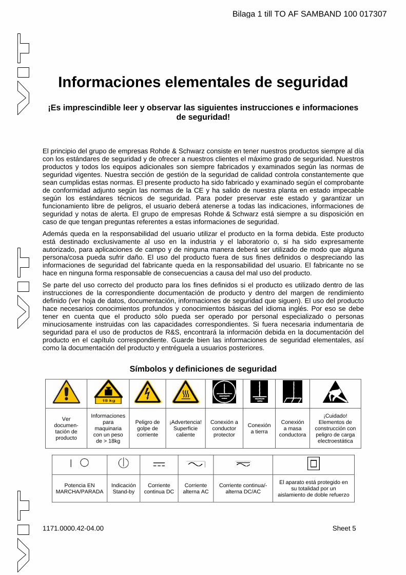
Símbolos y definiciones de seguridad
Ver documen-tación de producto
Informaciones para
maquinaria con un peso de > 18kg
Peligro de golpe de corriente
¡Advertencia! Superficie caliente
Conexión a conductor protector
Conexión a tierra
Conexión a masa
conductora
¡Cuidado! Elementos de
construcción con peligro de carga electroestática
Potencia EN MARCHA/PARADA
Indicación Stand-by
Corriente continua DC
Corriente alterna AC
Corriente continua/-alterna DC/AC
El aparato está protegido en su totalidad por un
aislamiento de doble refuerzo
1171.0000.42-04.00 Sheet 5
Bilaga 1 till TO AF SAMBAND 100 017307
Informaciones elementales de seguridad
Tener en cuenta las informaciones de seguridad sirve para tratar de evitar daños y peligros de toda clase. Es necesario de que se lean las siguientes informaciones de seguridad concienzudamente y se tengan en cuenta debidamente antes de la puesta en funcionamiento del producto. También deberán ser tenidas en cuenta las informaciones para la protección de personas que encontrarán en el capítulo correspondiente de la documentación de producto y que también son obligatorias de seguir. En las informaciones de seguridad actuales hemos juntado todos los objetos vendidos por el grupo de empresas Rohde & Schwarz bajo la denominación de „producto“, entre ellos también aparatos, instalaciones así como toda clase de accesorios.
Palabras de señal y su significado PELIGRO Identifica un peligro directo con riesgo elevado de provocar muerte o
lesiones de gravedad si no se toman las medidas oportunas.
ADVERTENCIA Identifica un posible peligro con riesgo medio de provocar muerte o lesiones (de gravedad) si no se toman las medidas oportunas.
ATENCIÓN Identifica un peligro con riesgo reducido de provocar lesiones de gravedad media o leve si no se toman las medidas oportunas.
AVISO Indica la posibilidad de utilizar mal el producto y a consecuencia dañarlo.
En la documentación del producto se emplea de forma sinónima el término CUIDADO.
Las palabras de señal corresponden a la definición habitual para aplicaciones civiles en el área económica europea. Pueden existir definiciones diferentes a esta definición en otras áreas económicas o en aplicaciones militares. Por eso se deberá tener en cuenta que las palabras de señal aquí descritas sean utilizadas siempre solamente en combinación con la correspondiente documentación de producto y solamente en combinación con el producto correspondiente. La utilización de las palabras de señal en combinación con productos o documentaciones que no les correspondan puede llevar a malinterpretaciones y tener por consecuencia daños en personas u objetos.
Informaciones de seguridad elementales trabajo y de prevención de accidentes. El producto solamente debe de ser abierto por personal especializado autorizado. Antes de efectuar trabajos en el producto o abrirlo deberá este ser desconectado de la corriente. El ajuste, el cambio de partes, la manutención y la reparación deberán ser solamente efectuadas por electricistas autorizados por R&S. Si se reponen partes con importancia para los aspectos de seguridad (por ejemplo el enchufe, los transformadores o los fusibles), solamente podrán ser sustituidos por partes originales. Después de cada recambio de partes elementales para la seguridad deberá ser efectuado un control de seguridad (control a primera vista, control de conductor protector, medición de resistencia de aislamiento, medición de la corriente conductora, control de funcionamiento).
1. El producto solamente debe ser utilizado según lo indicado por el fabricante referente a la situación y posición de funcionamiento sin que se obstruya la ventilación. Si no se convino de otra manera, es para los productos R&S válido lo que sigue: como posición de funcionamiento se define por principio la posición con el suelo de la caja para abajo, modo de protección IP 2X, grado de suciedad 2, categoría de sobrecarga eléctrica 2, utilizar solamente en estancias interiores, utilización hasta 2000 m sobre el nivel del mar, transporte hasta 4.500 m sobre el nivel del mar. Se aplicará una tolerancia de ±10% sobre el voltaje nominal y de ±5% sobre la frecuencia nominal.
2. En todos los trabajos deberán ser tenidas en cuenta las normas locales de seguridad de
1171.0000.42-04.00 Sheet 6
Bilaga 1 till TO AF SAMBAND 100 017307
Informaciones elementales de seguridad
3. Como en todo producto de fabricación industrial no puede ser excluido en general de que se produzcan al usarlo elementos que puedan generar alergias, los llamados elementos alergénicos (por ejemplo el níquel). Si se producieran en el trato con productos R&S reacciones alérgicas, como por ejemplo urticaria, estornudos frecuentes, irritación de la conjuntiva o dificultades al respirar, se deberá consultar inmediatamente a un médico para averiguar los motivos de estas reacciones.
4. Si productos / elementos de construcción son tratados fuera del funcionamiento definido de forma mecánica o térmica, pueden generarse elementos peligrosos (polvos de sustancia de metales pesados como por ejemplo plomo, berilio, níquel). La partición elemental del producto, como por ejemplo sucede en el tratamiento de materias residuales, debe de ser efectuada solamente por personal especializado para estos tratamientos. La partición elemental efectuada inadecuadamente puede generar daños para la salud. Se deben tener en cuenta las directivas nacionales referentes al tratamiento de materias residuales.
5. En el caso de que se produjeran agentes de peligro o combustibles en la aplicación del producto que debieran de ser transferidos a un tratamiento de materias residuales, como por ejemplo agentes refrigerantes que deben ser repuestos en periodos definidos, o aceites para motores, deberán ser tenidas en cuenta las prescripciones de seguridad del fabricante de estos agentes de peligro o combustibles y las regulaciones regionales para el tratamiento de materias residuales. Cuiden también de tener en cuenta en caso dado las prescripciones de seguridad especiales en la descripción del producto.
6. Ciertos productos, como por ejemplo las instalaciones de radiocomunicación RF, pueden a causa de su función natural, emitir una radiación electromagnética aumentada. En vista a la protección de la vida en desarrollo deberían ser protegidas personas embarazadas debidamente. También las personas con un bypass pueden correr peligro a causa de la radiación electromagnética.
El empresario/usuario está comprometido a valorar y señalar áreas de trabajo en las que se corra un riesgo aumentado de exposición a radiaciones para evitar riesgos.
7. La utilización de los productos requiere instrucciones especiales y una alta concentración en el manejo. Debe de ponerse por seguro de que las personas que manejen los productos estén a la altura de los requerimientos necesarios referente a sus aptitudes físicas, psíquicas y emocionales, ya que de otra manera no se pueden excluir lesiones o daños de objetos. El empresario lleva la responsabilidad de seleccionar el personal usuario apto para el manejo de los productos.
8. Antes de la puesta en marcha del producto se deberá tener por seguro de que la tensión preseleccionada en el producto equivalga a la del la red de distribución. Si es necesario cambiar la preselección de la tensión también se deberán en caso dabo cambiar los fusibles correspondientes del producto.
9. Productos de la clase de seguridad I con alimentación móvil y enchufe individual de producto solamente deberán ser conectados para el funcionamiento a tomas de corriente de contacto de seguridad y con conductor protector conectado.
10. Queda prohibida toda clase de interrupción intencionada del conductor protector, tanto en la toma de corriente como en el mismo producto. Puede tener como consecuencia el peligro de golpe de corriente por el producto. Si se utilizaran cables o enchufes de extensión se deberá poner al seguro que es controlado su estado técnico de seguridad.
11. Si el producto no está equipado con un interruptor para desconectarlo de la red, se deberá considerar el enchufe del cable de distribución como interruptor. En estos casos deberá asegurar de que el enchufe sea de fácil acceso y nabejo (según la medida del cable de distribución, aproximadamente 2 m). Los interruptores de función o electrónicos no son aptos para el corte de la red eléctrica. Si los productos sin interruptor están integrados en bastidores o instalaciones, se deberá instalar el interruptor al nivel de la instalación.
1171.0000.42-04.00 Sheet 7
Bilaga 1 till TO AF SAMBAND 100 017307
Informaciones elementales de seguridad
20. En caso de que los productos que son instalados fijamente en un lugar sean sin protector implementado, autointerruptor o similares objetos de protección, el circuito de suministro de corriente deberá estar protegido de manera que usuarios y productos estén suficientemente protegidos.
12. No utilice nunca el producto si está dañado el cable eléctrico. Compruebe regularmente el correcto estado de los cables de conexión a red. Asegure a través de las medidas de protección y de instalación adecuadas de que el cable de eléctrico no pueda ser dañado o de que nadie pueda ser dañado por él, por ejemplo al tropezar o por un golpe de corriente.
21. Por favor, no introduzca ningún objeto que no esté destinado a ello en los orificios de la caja del aparato. No vierta nunca ninguna clase de líquidos sobre o en la caja. Esto puede producir cortocircuitos en el producto y/o puede causar golpes de corriente, fuego o heridas.
13. Solamente está permitido el funcionamiento en redes de distribución TN/TT aseguradas con fusibles de como máximo 16 A (utilización de fusibles de mayor amperaje sólo previa consulta con el grupo de empresas Rohde & Schwarz). 22. Asegúrese con la protección adecuada de que
no pueda originarse en el producto una sobrecarga por ejemplo a causa de una tormenta. Si no se verá el personal que lo utilice expuesto al peligro de un golpe de corriente.
14. Nunca conecte el enchufe en tomas de corriente sucias o llenas de polvo. Introduzca el enchufe por completo y fuertemente en la toma de corriente. Si no tiene en consideración estas indicaciones se arriesga a que se originen chispas, fuego y/o heridas. 23. Los productos R&S no están protegidos contra
líquidos si no es que exista otra indicación, ver también punto 1. Si no se tiene en cuenta esto se arriesga el peligro de golpe de corriente para el usuario o de daños en el producto lo cual también puede llevar al peligro de personas.
15. No sobrecargue las tomas de corriente, los cables de extensión o los enchufes de extensión ya que esto pudiera causar fuego o golpes de corriente.
16. En las mediciones en circuitos de corriente con una tensión de entrada de Ueff > 30 V se deberá tomar las precauciones debidas para impedir cualquier peligro (por ejemplo medios de medición adecuados, seguros, limitación de tensión, corte protector, aislamiento etc.).
24. No utilice el producto bajo condiciones en las que pueda producirse y se hayan producido líquidos de condensación en o dentro del producto como por ejemplo cuando se desplaza el producto de un lugar frío a un lugar caliente.
17. En caso de conexión con aparatos de la técnica informática se deberá tener en cuenta que estos cumplan los requisitos del estándar IEC950/EN60950.
25. Por favor no cierre ninguna ranura u orificio del producto, ya que estas son necesarias para la ventilación e impiden que el producto se caliente demasiado. No pongan el producto encima de materiales blandos como por ejemplo sofás o alfombras o dentro de una caja cerrada, si esta no está suficientemente ventilada.
18. A menos que esté permitido expresamente, no retire nunca la tapa ni componentes de la carcasa mientras el producto esté en servicio. Esto pone a descubierto los cables y componentes eléctricos y puede causar heridas, fuego o daños en el producto.
26. No ponga el producto sobre aparatos que produzcan calor, como por ejemplo radiadores o calentadores. La temperatura ambiental no debe superar la temperatura máxima especificada en la hoja de datos.
19. Si un producto es instalado fijamente en un lugar, se deberá primero conectar el conductor protector fijo con el conductor protector del aparato antes de hacer cualquier otra conexión. La instalación y la conexión deberán ser efectuadas por un electricista especializado.
1171.0000.42-04.00 Sheet 8
Bilaga 1 till TO AF SAMBAND 100 017307
Informaciones elementales de seguridad
1171.0000.42-04.00 Sheet 9
27. Baterías y acumuladores no deben de ser expuestos a temperaturas altas o al fuego. Guardar baterías y acumuladores fuera del alcance de los niños. No cortocircuitar baterías ni acumuladores. Si las baterías o los acumuladores no son cambiados con la debida atención existirá peligro de explosión (atención células de litio). Cambiar las baterías o los acumuladores solamente por los del tipo R&S correspondiente (ver lista de piezas de recambio). Las baterías y acumuladores deben reutilizarse y no deben acceder a los vertederos. Las baterías y acumuladores que contienen plomo, mercurio o cadmio deben tratarse como residuos especiales. Respete en esta relación las normas nacionales de evacuación y reciclaje.
28. Por favor tengan en cuenta que en caso de un incendio pueden desprenderse del producto agentes venenosos (gases, líquidos etc.) que pueden generar daños a la salud.
29. El producto puede poseer un peso elevado. Muévalo con cuidado para evitar lesiones en la espalda u otras partes corporales.
30. No sitúe el producto encima de superficies, vehículos, estantes o mesas, que por sus características de peso o de estabilidad no sean aptas para él. Siga siempre las instrucciones de instalación del fabricante cuando instale y asegure el producto en objetos o estructuras (por ejemplo paredes y estantes).
31. Las asas instaladas en los productos sirven solamente de ayuda para el manejo que solamente está previsto para personas. Por eso no está permitido utilizar las asas para la sujeción en o sobre medios de transporte como por ejemplo grúas, carretillas elevadoras
de horquilla, carros etc. El usuario es responsable de que los productos sean sujetados de forma segura a los medios de transporte y de que las prescripciones de seguridad del fabricante de los medios de transporte sean observadas. En caso de que no se tengan en cuenta pueden causarse daños en personas y objetos.
32. Si llega a utilizar el producto dentro de un vehículo, queda en la responsabilidad absoluta del conductor que conducir el vehículo de manera segura. Asegure el producto dentro del vehículo debidamente para evitar en caso de un accidente las lesiones u otra clase de daños. No utilice nunca el producto dentro de un vehículo en movimiento si esto pudiera distraer al conductor. Siempre queda en la responsabilidad absoluta del conductor la seguridad del vehículo. El fabricante no asumirá ninguna clase de responsabilidad por accidentes o colisiones.
33. Dado el caso de que esté integrado un producto de láser en un producto R&S (por ejemplo CD/DVD-ROM) no utilice otras instalaciones o funciones que las descritas en la documentación de producto. De otra manera pondrá en peligro su salud, ya que el rayo láser puede dañar irreversiblemente sus ojos. Nunca trate de descomponer estos productos. Nunca mire dentro del rayo láser.
34. Antes de proceder a la limpieza, desconecte el producto de la red. Realice la limpieza con un paño suave, que no se deshilache. No utilice de ninguna manera agentes limpiadores químicos como, por ejemplo, alcohol, acetona o nitrodiluyente.
Bilaga 1 till TO AF SAMBAND 100 017307
6102.0307.01 CE D/E-3
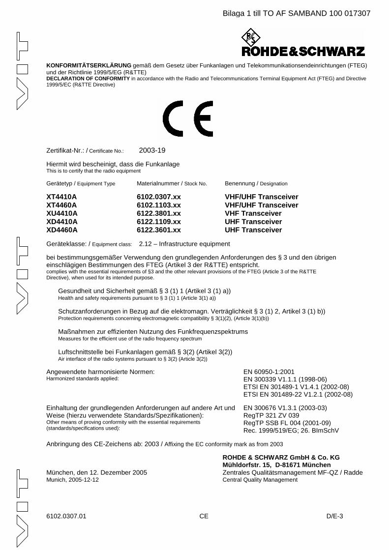
KONFORMITÄTSERKLÄRUNG gemäß dem Gesetz über Funkanlagen und Telekommunikationsendeinrichtungen (FTEG) und der Richtlinie 1999/5/EG (R&TTE) DECLARATION OF CONFORMITY in accordance with the Radio and Telecommunications Terminal Equipment Act (FTEG) and Directive 1999/5/EC (R&TTE Directive)
Zertifikat-Nr.: / Certificate No.: 2003-19
Hiermit wird bescheinigt, dass die Funkanlage This is to certify that the radio equipment Gerätetyp / Equipment Type Materialnummer / Stock No. Benennung / Designation
XT4410A 6102.0307.xx VHF/UHF Transceiver XT4460A 6102.1103.xx VHF/UHF Transceiver XU4410A 6122.3801.xx VHF Transceiver XD4410A 6122.1109.xx UHF Transceiver XD4460A 6122.3601.xx UHF Transceiver Geräteklasse: / Equipment class: 2.12 – Infrastructure equipment
bei bestimmungsgemäßer Verwendung den grundlegenden Anforderungen des § 3 und den übrigen einschlägigen Bestimmungen des FTEG (Artikel 3 der R&TTE) entspricht. complies with the essential requirements of §3 and the other relevant provisions of the FTEG (Article 3 of the R&TTE Directive), when used for its intended purpose. • Gesundheit und Sicherheit gemäß § 3 (1) 1 (Artikel 3 (1) a)) • Health and safety requirements pursuant to § 3 (1) 1 (Article 3(1) a)) • Schutzanforderungen in Bezug auf die elektromagn. Verträglichkeit § 3 (1) 2, Artikel 3 (1) b)) • Protection requirements concerning electromagnetic compatibility § 3(1)(2), (Article 3(1)(b)) • Maßnahmen zur effizienten Nutzung des Funkfrequenzspektrums • Measures for the efficient use of the radio frequency spectrum • Luftschnittstelle bei Funkanlagen gemäß § 3(2) (Artikel 3(2)) • Air interface of the radio systems pursuant to § 3(2) (Article 3(2)) Angewendete harmonisierte Normen: Harmonized standards applied:
EN 60950-1:2001 EN 300339 V1.1.1 (1998-06) ETSI EN 301489-1 V1.4.1 (2002-08) ETSI EN 301489-22 V1.2.1 (2002-08)
Einhaltung der grundlegenden Anforderungen auf andere Art und Weise (hierzu verwendete Standards/Spezifikationen): Other means of proving conformity with the essential requirements (standards/specifications used):
EN 300676 V1.3.1 (2003-03) RegTP 321 ZV 039 RegTP SSB FL 004 (2001-09) Rec. 1999/519/EG; 26. BImSchV
Anbringung des CE-Zeichens ab: 2003 / Affixing the EC conformity mark as from 2003
ROHDE & SCHWARZ GmbH & Co. KG Mühldorfstr. 15, D-81671 München
München, den 12. Dezember 2005 Zentrales Qualitätsmanagement MF-QZ / Radde Munich, 2005-12-12 Central Quality Management
Bilaga 1 till TO AF SAMBAND 100 017307

Bilaga 1 till TO AF SAMBAND 100 017307
Bilaga 1 till TO AF SAMBAND 100 017307

Bilaga 1 till TO AF SAMBAND 100 017307
Radio Communication Systems DivisionDocumentation Dept.Mühldorfstr. 15
D-81671 MünchenFax +49 89 4129 12690
0708 6125.1651.12.02 - 001 please turn over
E V A L U A T I O N O F M A N U A L Shere: Operating Manual, Id. No. 6125.1651.12.02, R&S M3SR Transceivers
Dear Sirs,
we constantly try to improve our technical manuals, so that you, our customer gets thebest possible benefit from them.
In order to become better, we need your help and your opinion on the manuals. There-fore, we would like you to evaluate the accompanying manual and tell us your opinionabout it. In order to make the job easy for you, we have designed the following matrix.Please tick where appropriate.
1. What is your general impression of the manual?
lousy not so good quite ok good excellent
2. How do you assess the detail and depth of information in general?
far too too much all information not enough important itemsdetailed information contained information missing
3. How do you assess the size of the manual in general?
far too a bit too appropriate to easy to very clearlybulky thick the equipment handle presented
4. How do you assess the structure of the manual?
opaque difficult to quite ok easy to find very user-understand information friendly
5. How do you assess the understandability (language) of manual?
very difficult complicated normal to easy to very user-to follow language understand understand friendly
Bilaga 1 till TO AF SAMBAND 100 017307

0708 6125.1651.12.02 - 002
E V A L U A T I O N O F M A N U A L SOperating Manual, Id. No. 6125.1651.12.02, R&S M3SR Transceivers
6. How do you rate the number of illustrations?
far too a bit too just about could be not enoughmany many right more illustrations
7. How do you rate the quality of illustrations?
lousy not so good quite ok good excellent
8. How do you assess the balance of text to illustrations?
lousy not so good quite ok good excellent
Further Comments and Suggestions for Improvement:
Date / Signature / Department
Bilaga 1 till TO AF SAMBAND 100 017307
Notices R&S M3SR Transceivers
N.1 6125.1651.12.01
Definitions
Check In appropriate measurements by means of the specified test equipment, proper functioning of a unit or module is estab-lished.
Discolouration Components such as connectors and printed circuit boards are examined if they have changed colour due to temperature ef-fects and thus differ widely from their normal condition.
Disconnect Pull off connector.Examine In case of trouble the unit / module or components such as e.g.
connectors, are to be thoroughly checked for obvious mechani-cal damage.
Functional check This means that components / modules / units are checked for proper functioning while installed.
Hazardous voltages Voltages > 30 Vrms or 50 Vpp (AC) or 50 V (DC) Make sure Ascertain whether all mentioned requirements are met or all
measures are taken to establish the required condition. Open Access is to be gained to the unit / module by observing the
given instructions and safety precautions. Perfect condition This means that a component / module / unit has to be in a
state which does not give cause to complaints. Replacement In case of trouble the replacement of modules is carried out in
order to localize and eliminate the fault.Replace Components / modules / units which - due to damage and / or
other defects - no longer meet the respective requirements or components / modules / units which during troubleshooting were identified as the cause of fault, are to be replaced.
Visual examination This is a visual inspection of the outer appearance and com- pleteness of a component / module / unit without manual inter-ference by the examiner. This does not include the necessary preparations and finishing work such as opening and closing of covers or similar.
Bilaga 1 till TO AF SAMBAND 100 017307
R&S M3SR Transceivers Notices
6125.1651.12.01 N.2
Notices
The three different notices used in this documentation have the following meaning:
W A R N I N G
This heading is used to indicate that inaccurate observance or nonobservance of in-structions or methods can cause injury or even fatal accidents or during an operation
described hazardous material can be set free in the unit or system.
C A U T I O N
This heading is used to indicate that inaccurate observance or nonobservance of instructions or methods can cause damage to the unit.
Note:This heading is used to draw the reader’s attention to a particular fact.
Bilaga 1 till TO AF SAMBAND 100 017307
Notices R&S M3SR Transceivers
N.3 6125.1651.12.01
User Information
Purpose of the Manual
This Manual provides all information the operators and service staff need to maintain level 1 of repairs.
lt contains all necessary information and instructions concerning the installation, putting into operationand control of the unit, plus troubleshooting instructions down to unit level. In case of trouble this allowsstraightforward error localization as well as easy replacement of the unit.
Measuring Units
In this Manual the basic SI measuring units and units coherently derived from them are used by pref-erence. In exceptional cases units legally derived from the SI units acc. to DIN1301 may also be used.
We recommend to keep complete spare units in store.
Bilaga 1 till TO AF SAMBAND 100 017307
R&S M3SR Transceivers Notices
6125.1651.12.01 N.4
Bilaga 1 till TO AF SAMBAND 100 017307
List of Abbreviations R&S M3SR Transceivers
Bilaga 1 till TO AF SAMBAND 100 017307
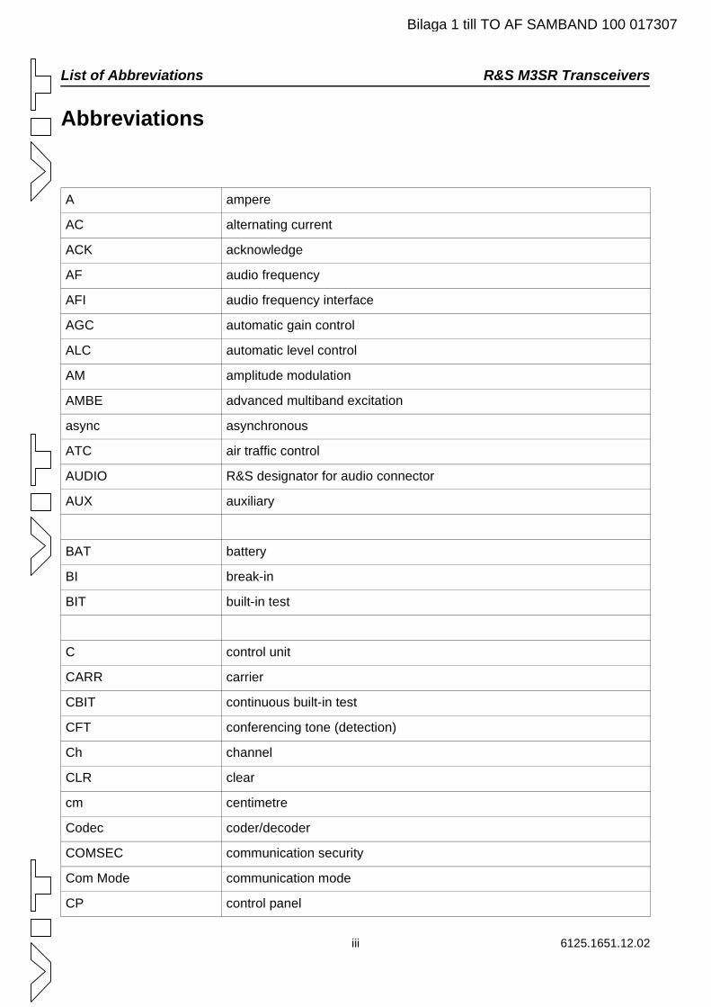
Abbreviations
A ampere
AC alternating current
ACK acknowledge
AF audio frequency
AFI audio frequency interface
AGC automatic gain control
ALC automatic level control
AM amplitude modulation
AMBE advanced multiband excitation
async asynchronous
ATC air traffic control
AUDIO R&S designator for audio connector
AUX auxiliary
BAT battery
BI break-in
BIT built-in test
C control unit
CARR carrier
CBIT continuous built-in test
CFT conferencing tone (detection)
Ch channel
CLR clear
cm centimetre
Codec coder/decoder
COMSEC communication security
Com Mode communication mode
CP control panel
iii 6125.1651.12.02
R&S M3SR Transceivers List of Abbreviations
Bilaga 1 till TO AF SAMBAND 100 017307
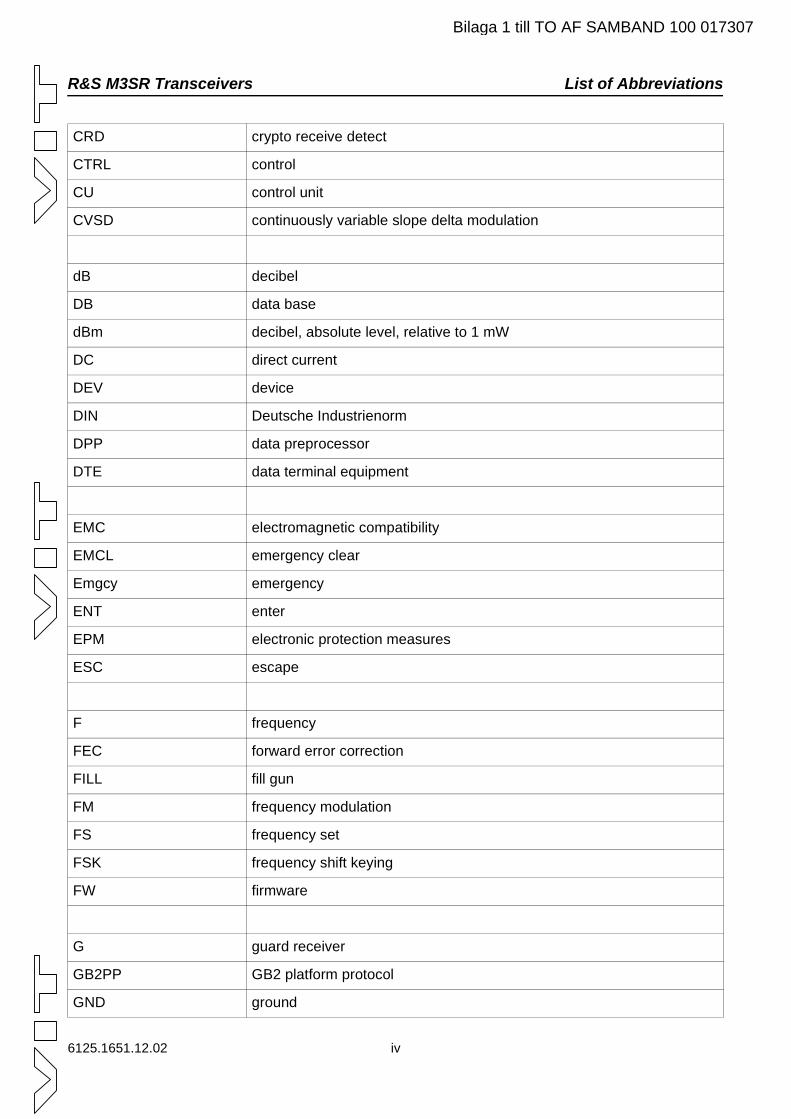
CRD crypto receive detect
CTRL control
CU control unit
CVSD continuously variable slope delta modulation
dB decibel
DB data base
dBm decibel, absolute level, relative to 1 mW
DC direct current
DEV device
DIN Deutsche Industrienorm
DPP data preprocessor
DTE data terminal equipment
EMC electromagnetic compatibility
EMCL emergency clear
Emgcy emergency
ENT enter
EPM electronic protection measures
ESC escape
F frequency
FEC forward error correction
FILL fill gun
FM frequency modulation
FS frequency set
FSK frequency shift keying
FW firmware
G guard receiver
GB2PP GB2 platform protocol
GND ground
6125.1651.12.02 iv
List of Abbreviations R&S M3SR Transceivers
Bilaga 1 till TO AF SAMBAND 100 017307
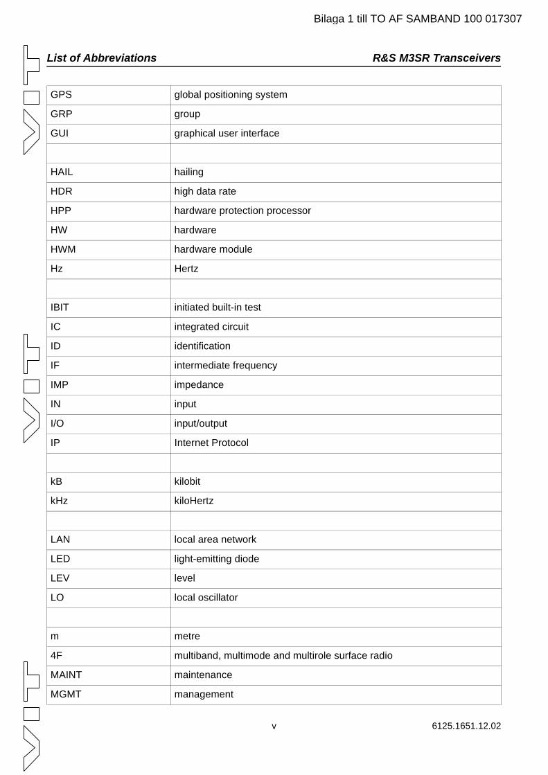
GPS global positioning system
GRP group
GUI graphical user interface
HAIL hailing
HDR high data rate
HPP hardware protection processor
HW hardware
HWM hardware module
Hz Hertz
IBIT initiated built-in test
IC integrated circuit
ID identification
IF intermediate frequency
IMP impedance
IN input
I/O input/output
IP Internet Protocol
kB kilobit
kHz kiloHertz
LAN local area network
LED light-emitting diode
LEV level
LO local oscillator
m metre
4F multiband, multimode and multirole surface radio
MAINT maintenance
MGMT management
v 6125.1651.12.02
R&S M3SR Transceivers List of Abbreviations
Bilaga 1 till TO AF SAMBAND 100 017307
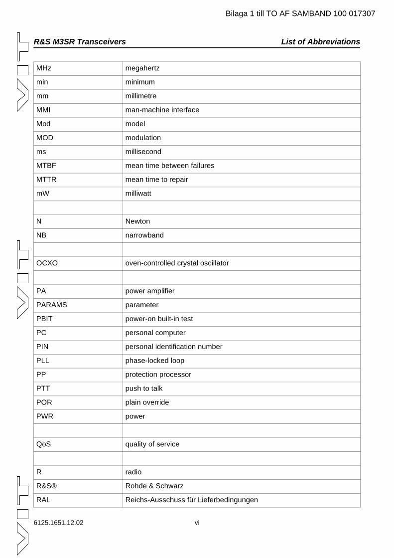
MHz megahertz
min minimum
mm millimetre
MMI man-machine interface
Mod model
MOD modulation
ms millisecond
MTBF mean time between failures
MTTR mean time to repair
mW milliwatt
N Newton
NB narrowband
OCXO oven-controlled crystal oscillator
PA power amplifier
PARAMS parameter
PBIT power-on built-in test
PC personal computer
PIN personal identification number
PLL phase-locked loop
PP protection processor
PTT push to talk
POR plain override
PWR power
QoS quality of service
R radio
R&S® Rohde & Schwarz
RAL Reichs-Ausschuss für Lieferbedingungen
6125.1651.12.02 vi
List of Abbreviations R&S M3SR Transceivers
Bilaga 1 till TO AF SAMBAND 100 017307
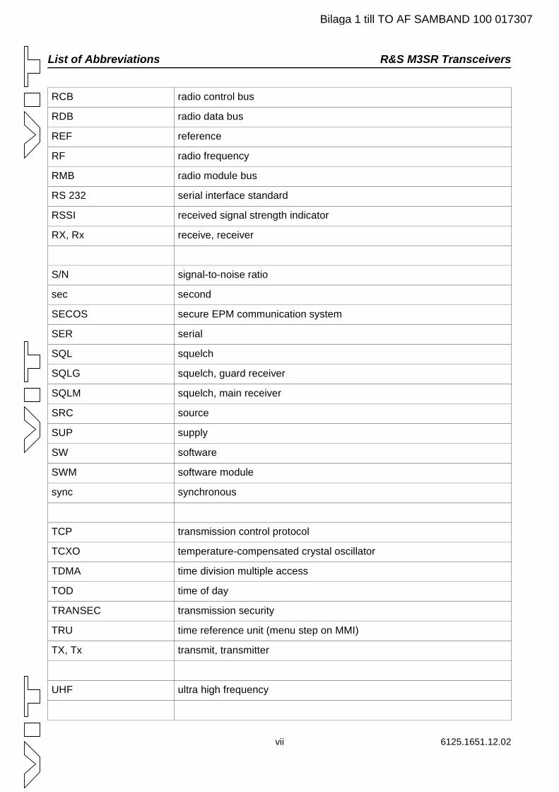
RCB radio control bus
RDB radio data bus
REF reference
RF radio frequency
RMB radio module bus
RS 232 serial interface standard
RSSI received signal strength indicator
RX, Rx receive, receiver
S/N signal-to-noise ratio
sec second
SECOS secure EPM communication system
SER serial
SQL squelch
SQLG squelch, guard receiver
SQLM squelch, main receiver
SRC source
SUP supply
SW software
SWM software module
sync synchronous
TCP transmission control protocol
TCXO temperature-compensated crystal oscillator
TDMA time division multiple access
TOD time of day
TRANSEC transmission security
TRU time reference unit (menu step on MMI)
TX, Tx transmit, transmitter
UHF ultra high frequency
vii 6125.1651.12.02
R&S M3SR Transceivers List of Abbreviations
Bilaga 1 till TO AF SAMBAND 100 017307
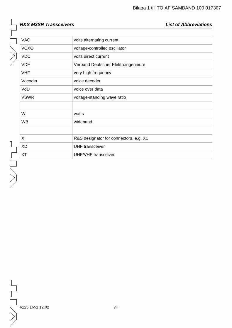
VAC volts alternating current
VCXO voltage-controlled oscillator
VDC volts direct current
VDE Verband Deutscher Elektroingenieure
VHF very high frequency
Vocoder voice decoder
VoD voice over data
VSWR voltage-standing wave ratio
W watts
WB wideband
X R&S designator for connectors, e.g. X1
XD UHF transceiver
XT UHF/VHF transceiver
6125.1651.12.02 viii
Overview R&S M3SR Transceivers
ix 6125.1651.12.02
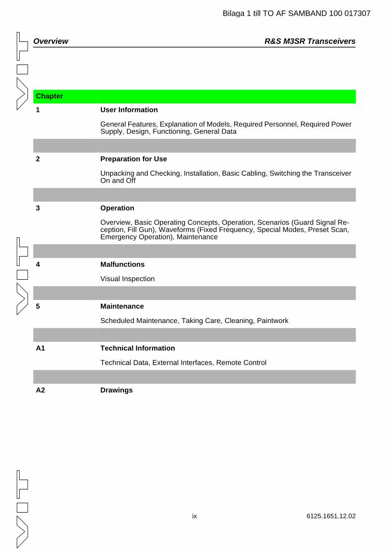
Chapter
1 User Information
General Features, Explanation of Models, Required Personnel, Required Power Supply, Design, Functioning, General Data
2 Preparation for Use
Unpacking and Checking, Installation, Basic Cabling, Switching the Transceiver On and Off
3 Operation
Overview, Basic Operating Concepts, Operation, Scenarios (Guard Signal Re-ception, Fill Gun), Waveforms (Fixed Frequency, Special Modes, Preset Scan, Emergency Operation), Maintenance
4 Malfunctions
Visual Inspection
5 Maintenance
Scheduled Maintenance, Taking Care, Cleaning, Paintwork
A1 Technical Information
Technical Data, External Interfaces, Remote Control
A2 Drawings
Bilaga 1 till TO AF SAMBAND 100 017307
R&S M3SR Transceivers Overview
6125.1651.12.02 x
Bilaga 1 till TO AF SAMBAND 100 017307
R&S M3SR Transceivers
Contents
Bilaga 1 till TO AF SAMBAND 100 017307
1 User Information...............................................................................................1.11.1 General Features ...........................................................................................................1.21.2 Explanation of Models ....................................................................................................1.41.3 Required Personnel........................................................................................................1.51.4 Required Power Supply..................................................................................................1.51.5 Design, e.g. R&S XT 4410A, Mod. 22............................................................................1.61.6 Functioning, e.g. R&S XT 4410A, Mod. 22 ....................................................................1.81.7 General Data ................................................................................................................1.101.8 Recommended Accessories.........................................................................................1.102 Preparation for Use ..........................................................................................2.12.1 R&S M3SR - Unpacking.................................................................................................2.12.2 R&S M3SR - Installation.................................................................................................2.22.3 R&S M3SR - Connect Procedures .................................................................................2.42.3.1 Basic Connection ...........................................................................................................2.52.3.2 Connection of Peripheral Equipment..............................................................................2.72.3.2.1 Filters..............................................................................................................................2.72.3.2.2 Power Amplifiers ..........................................................................................................2.122.4 R&S M3SR - Power Up ................................................................................................2.182.5 R&S M3SR - Power Down ...........................................................................................2.203 Operation...........................................................................................................3.13.1 Overview ........................................................................................................................3.13.2 Basic Operating Concepts..............................................................................................3.43.2.1 Radio Settings/Displays via Front Panel ........................................................................3.43.2.2 Operation via Control Unit ..............................................................................................3.73.2.2.1 Graphical User Interface Design ....................................................................................3.83.2.2.2 Softkeys........................................................................................................................3.103.2.2.3 Control Unit LEDs.........................................................................................................3.113.2.2.4 Menu Page Design.......................................................................................................3.113.2.2.4.1 Header..........................................................................................................................3.123.2.2.4.2 Central Area .................................................................................................................3.153.2.2.5 Control Elements..........................................................................................................3.183.2.2.5.1 Navigation ....................................................................................................................3.183.2.2.5.2 Settings ........................................................................................................................3.183.2.2.5.3 Greyed-out Softkey Labels...........................................................................................3.193.2.2.5.4 Inactive Data Elements ................................................................................................3.193.2.2.5.5 Context Menu ...............................................................................................................3.203.2.2.6 Screen Saver................................................................................................................3.223.2.2.7 Suspend Mode .............................................................................................................3.223.3 Operation......................................................................................................................3.233.3.1 Operating / Maintenance Mode ....................................................................................3.233.3.1.1 Operating Mode............................................................................................................3.233.3.1.2 Maintenance Mode.......................................................................................................3.293.3.2 Manual Mode / Preset Mode ........................................................................................3.323.3.2.1 Manual Mode................................................................................................................3.323.3.3 Preset Mode .................................................................................................................3.343.3.4 Local / Remote Mode ...................................................................................................3.383.3.4.1 Local Mode...................................................................................................................3.393.3.4.2 Remote Mode...............................................................................................................3.41
1 6125.1651.12.02
Contents R&S M3SR Transceivers
Bilaga 1 till TO AF SAMBAND 100 017307
3.3.4.3 Control Unit / Radio Connection...................................................................................3.423.4 Scenarios .....................................................................................................................3.453.4.1 Guard Signal Reception ...............................................................................................3.453.4.2 Fill Gun (Fixed Frequency)...........................................................................................3.463.5 Waveforms ...................................................................................................................3.483.5.1 Fixed Frequency...........................................................................................................3.483.5.1.1 Functions......................................................................................................................3.483.5.1.2 Manual Mode................................................................................................................3.513.5.1.3 Preset Mode .................................................................................................................3.533.5.2 Special Modes..............................................................................................................3.543.5.2.1 Link11 / LinkY...............................................................................................................3.573.5.2.1.1 Introduction...................................................................................................................3.573.5.2.1.2 Manual Mode................................................................................................................3.593.5.2.1.3 Preset Mode .................................................................................................................3.593.5.2.2 High Data Rate.............................................................................................................3.603.5.2.2.1 Introduction...................................................................................................................3.603.5.2.2.2 Manual Mode................................................................................................................3.623.5.2.2.3 Preset Mode .................................................................................................................3.623.5.3 Emergency Operation ..................................................................................................3.633.5.4 Preset Scan Mode........................................................................................................3.653.5.4.1 Introduction...................................................................................................................3.653.5.4.2 Activating Preset Scan .................................................................................................3.673.5.4.3 Limitations of Preset Scan............................................................................................3.713.6 Maintenance.................................................................................................................3.723.6.1 Control Unit and Radio .................................................................................................3.723.6.1.1 Troubleshooting............................................................................................................3.723.6.1.1.1 PBIT .............................................................................................................................3.723.6.1.1.2 CBIT .............................................................................................................................3.723.6.1.1.3 IBIT...............................................................................................................................3.743.6.1.2 Error List.......................................................................................................................3.763.6.2 Configuration and Status..............................................................................................3.783.6.2.1 Inventory.......................................................................................................................3.783.6.2.2 Address Configuration..................................................................................................3.803.6.3 Radio ............................................................................................................................3.843.6.3.1 Radio Time and Date ...................................................................................................3.843.6.3.2 Default Setting..............................................................................................................3.853.6.3.3 Radio Modules .............................................................................................................3.913.6.3.3.1 Synthesizer...................................................................................................................3.913.6.3.3.2 Receiver .......................................................................................................................3.923.6.3.3.3 Guard Receiver ............................................................................................................3.933.6.3.3.4 Protection Processor (if installed).................................................................................3.943.6.3.3.5 Power Amplifier ............................................................................................................3.953.6.3.3.5.1 Configuration of Power Amplifier..................................................................................3.953.6.3.3.5.2 Configuration of Filter ...................................................................................................3.983.6.3.3.6 Platform ........................................................................................................................3.993.6.3.3.7 Audio Interface ...........................................................................................................3.1003.6.3.3.8 Up/Down Converter R&S UX 4401 ............................................................................3.1023.6.3.4 Option Management...................................................................................................3.1033.6.3.5 Resource Management ..............................................................................................3.1043.6.3.6 Audio Monitoring ........................................................................................................3.1093.6.3.7 I/O Mapping................................................................................................................3.110
2 6125.1651.12.02
R&S M3SR Transceivers Contents
Bilaga 1 till TO AF SAMBAND 100 017307
3.6.3.8 Protocol Configuration................................................................................................3.1123.6.3.9 PTT Timeout Configuration ........................................................................................3.1133.6.3.10 Preset Configuration...................................................................................................3.1153.6.3.10.1 Preset Settings ...........................................................................................................3.1153.6.4 Control Unit ................................................................................................................3.1203.6.4.1 MMI Parameters.........................................................................................................3.1203.6.4.2 Default Settings ..........................................................................................................3.1223.6.4.3 Test of Key Functions.................................................................................................3.1234 Malfunctions .....................................................................................................4.14.1 Visual Inspection ............................................................................................................4.15 Maintenance......................................................................................................5.15.1 Scheduled Maintenance.................................................................................................5.15.1.1 Calibration ......................................................................................................................5.45.2 Care, Cleaning ...............................................................................................................5.75.2.1 Care................................................................................................................................5.75.2.2 Cleaning .........................................................................................................................5.85.3 Retouching the Paint Work.............................................................................................5.9A1 Technical Information ................................................................................... A1.1A1.1 Technical Data ............................................................................................................ A1.1A1.2 External Interfaces ...................................................................................................... A1.2A1.3 Remote Control ........................................................................................................... A1.3A2 Drawings ........................................................................................................ A2.1
6125.1651.12.02 3
R&S M3SR Transceivers
Figures
Bilaga 1 till TO AF SAMBAND 100 017307
Fig. 1.1 R&S M3SR Transceiver, Front View . . . . . . . . . . . . . . . . . . . . . . . . . . . . . . . . . . . . . . .1.2Fig. 1.2 Power Supply R&S IN 4000A. . . . . . . . . . . . . . . . . . . . . . . . . . . . . . . . . . . . . . . . . . . . .1.5Fig. 1.3 Top View of e.g. R&S XT 4410A, Mod. 22 (without Cover) . . . . . . . . . . . . . . . . . . . . . .1.7Fig. 1.4 Block Diagram of e.g. R&S XT 4410A, Mod. 22. . . . . . . . . . . . . . . . . . . . . . . . . . . . . . .1.9Fig. 2.1 Installation into a 19" Rack. . . . . . . . . . . . . . . . . . . . . . . . . . . . . . . . . . . . . . . . . . . . . . .2.3Fig. 2.2 Rear Cabling . . . . . . . . . . . . . . . . . . . . . . . . . . . . . . . . . . . . . . . . . . . . . . . . . . . . . . . . .2.5Fig. 2.3 Front Cabling, e.g. R&S XT 4410A (Ruggedized) . . . . . . . . . . . . . . . . . . . . . . . . . . . . .2.6Fig. 2.4 Wiring Diagram R&S M3SR Transceiver - e.g. R&S FD 221 . . . . . . . . . . . . . . . . . . . .2.10Fig. 2.5 Wiring Diagram R&S M3SR Transceiver - e.g. R&S FD 213A. . . . . . . . . . . . . . . . . . .2.11Fig. 2.6 Wiring Diagram R&S M3SR Transceiver - R&S VD 480L . . . . . . . . . . . . . . . . . . . . . .2.14Fig. 2.7 Wiring Diagram R&S M3SR Transceiver - R&S VU 220L . . . . . . . . . . . . . . . . . . . . . .2.15Fig. 2.8 Wiring Diagram R&S M3SR Transceiver - e.g. R&S FD 430 . . . . . . . . . . . . . . . . . . . .2.17Fig. 2.9 Switching the Transceiver On . . . . . . . . . . . . . . . . . . . . . . . . . . . . . . . . . . . . . . . . . . .2.18Fig. 2.10 Switching the Transceiver Off . . . . . . . . . . . . . . . . . . . . . . . . . . . . . . . . . . . . . . . . . . .2.20Fig. 3.1 R&S M3SR Radios. . . . . . . . . . . . . . . . . . . . . . . . . . . . . . . . . . . . . . . . . . . . . . . . . . . . .3.2Fig. 3.2 Example of a Network Topology . . . . . . . . . . . . . . . . . . . . . . . . . . . . . . . . . . . . . . . . . .3.3Fig. 3.3 Radio Front Panel . . . . . . . . . . . . . . . . . . . . . . . . . . . . . . . . . . . . . . . . . . . . . . . . . . . . .3.4Fig. 3.4 Control Unit Front Panel. . . . . . . . . . . . . . . . . . . . . . . . . . . . . . . . . . . . . . . . . . . . . . . . .3.7Fig. 3.5 Extract of Menu Structure, Example. . . . . . . . . . . . . . . . . . . . . . . . . . . . . . . . . . . . . . . .3.9Fig. 3.6 Location of Softkeys . . . . . . . . . . . . . . . . . . . . . . . . . . . . . . . . . . . . . . . . . . . . . . . . . . .3.10Fig. 3.7 Menu Page Design with Indicators. . . . . . . . . . . . . . . . . . . . . . . . . . . . . . . . . . . . . . . .3.11Fig. 3.8 Header Design . . . . . . . . . . . . . . . . . . . . . . . . . . . . . . . . . . . . . . . . . . . . . . . . . . . . . . .3.12Fig. 3.9 Example: Fixed Frequency Central Area . . . . . . . . . . . . . . . . . . . . . . . . . . . . . . . . . . .3.15Fig. 3.10 Example: Fixed Frequency Central Area - CBIT Error Message . . . . . . . . . . . . . . . . .3.16Fig. 3.11 Example - Folder View of Radio Modules . . . . . . . . . . . . . . . . . . . . . . . . . . . . . . . . . .3.17Fig. 3.12 Context Menu . . . . . . . . . . . . . . . . . . . . . . . . . . . . . . . . . . . . . . . . . . . . . . . . . . . . . . . .3.20Fig. 3.13 Context Menu - Fixed Frequency Preset Mode . . . . . . . . . . . . . . . . . . . . . . . . . . . . . .3.21Fig. 3.14 Example of Remote Access with Fixed Frequency . . . . . . . . . . . . . . . . . . . . . . . . . . .3.23Fig. 3.15 Access Rights - All Control Units in Monitoring Mode . . . . . . . . . . . . . . . . . . . . . . . . .3.25Fig. 3.16 Access Rights - Concurrent Access Rights . . . . . . . . . . . . . . . . . . . . . . . . . . . . . . . . .3.26Fig. 3.17 Access Rights - Fixed Access Rights. . . . . . . . . . . . . . . . . . . . . . . . . . . . . . . . . . . . . .3.27Fig. 3.18 Access Rights - Rejected Access Requests . . . . . . . . . . . . . . . . . . . . . . . . . . . . . . . .3.28Fig. 3.19 Maintenance - Overview. . . . . . . . . . . . . . . . . . . . . . . . . . . . . . . . . . . . . . . . . . . . . . . .3.29Fig. 3.20 Radio Maintenance Menu . . . . . . . . . . . . . . . . . . . . . . . . . . . . . . . . . . . . . . . . . . . . . .3.30Fig. 3.21 Maintenance - Supervisor Access . . . . . . . . . . . . . . . . . . . . . . . . . . . . . . . . . . . . . . . .3.31Fig. 3.22 Main Menu - Example of Manual Mode . . . . . . . . . . . . . . . . . . . . . . . . . . . . . . . . . . . .3.32Fig. 3.23 Preset Organisation . . . . . . . . . . . . . . . . . . . . . . . . . . . . . . . . . . . . . . . . . . . . . . . . . . .3.35Fig. 3.24 Main Menu - Loading a Preset Page . . . . . . . . . . . . . . . . . . . . . . . . . . . . . . . . . . . . . .3.36Fig. 3.25 Main Menu - Preset Mode . . . . . . . . . . . . . . . . . . . . . . . . . . . . . . . . . . . . . . . . . . . . . .3.37Fig. 3.26 Overview - Local and Remote Mode . . . . . . . . . . . . . . . . . . . . . . . . . . . . . . . . . . . . . .3.38Fig. 3.27 Access Rights in Local Mode . . . . . . . . . . . . . . . . . . . . . . . . . . . . . . . . . . . . . . . . . . . .3.39Fig. 3.28 Remote Control Unit - Lost Connection because of Local Mode . . . . . . . . . . . . . . . . .3.40Fig. 3.29 Example of a Remote Access . . . . . . . . . . . . . . . . . . . . . . . . . . . . . . . . . . . . . . . . . . .3.41Fig. 3.30 Selecting a Radio to be Connected . . . . . . . . . . . . . . . . . . . . . . . . . . . . . . . . . . . . . . .3.42Fig. 3.31 Successful Connection to a Radio . . . . . . . . . . . . . . . . . . . . . . . . . . . . . . . . . . . . . . . .3.44Fig. 3.32 Example of Emergency Mode . . . . . . . . . . . . . . . . . . . . . . . . . . . . . . . . . . . . . . . . . . .3.45Fig. 3.33 Radio - Front View . . . . . . . . . . . . . . . . . . . . . . . . . . . . . . . . . . . . . . . . . . . . . . . . . . . .3.46Fig. 3.34 Example of Radio in Load Mode . . . . . . . . . . . . . . . . . . . . . . . . . . . . . . . . . . . . . . . . .3.47
4 6125.1651.12.02
R&S M3SR Transceivers Figures
Bilaga 1 till TO AF SAMBAND 100 017307
Fig. 3.35 Example - Selecting a Communication Mode in Fixed Frequency. . . . . . . . . . . . . . . .3.49Fig. 3.36 Fixed Frequency, Main Menu, page 1 . . . . . . . . . . . . . . . . . . . . . . . . . . . . . . . . . . . . .3.51Fig. 3.37 Fixed Frequency, Main Menu, page 2 . . . . . . . . . . . . . . . . . . . . . . . . . . . . . . . . . . . . .3.52Fig. 3.38 Example - Fixed Frequency in Preset Mode . . . . . . . . . . . . . . . . . . . . . . . . . . . . . . . .3.53Fig. 3.39 Selection of Special Modes Menu from the Main Menu (Manual Mode) . . . . . . . . . . .3.54Fig. 3.40 Special Mode Menu (Manual Mode) . . . . . . . . . . . . . . . . . . . . . . . . . . . . . . . . . . . . . .3.55Fig. 3.41 Selection of a Special Mode from the Main Menu (Preset Mode) . . . . . . . . . . . . . . . .3.56Fig. 3.42 Connection of Link11 / LinkY Terminal to R&S M3SR Radio. . . . . . . . . . . . . . . . . . . .3.58Fig. 3.43 Link11 / LinkY Menu. . . . . . . . . . . . . . . . . . . . . . . . . . . . . . . . . . . . . . . . . . . . . . . . . . .3.59Fig. 3.44 Connection of an External HDR Modem . . . . . . . . . . . . . . . . . . . . . . . . . . . . . . . . . . .3.61Fig. 3.45 High Data Rate Menu. . . . . . . . . . . . . . . . . . . . . . . . . . . . . . . . . . . . . . . . . . . . . . . . . .3.62Fig. 3.46 Example - Emergency Mode in Preset Mode. . . . . . . . . . . . . . . . . . . . . . . . . . . . . . . .3.63Fig. 3.47 Example - Emergency Mode in Manual Mode . . . . . . . . . . . . . . . . . . . . . . . . . . . . . . .3.64Fig. 3.48 Main Menu - Example of Manual Mode . . . . . . . . . . . . . . . . . . . . . . . . . . . . . . . . . . . .3.67Fig. 3.49 Context Menu . . . . . . . . . . . . . . . . . . . . . . . . . . . . . . . . . . . . . . . . . . . . . . . . . . . . . . . .3.68Fig. 3.50 Preset Scan Menu . . . . . . . . . . . . . . . . . . . . . . . . . . . . . . . . . . . . . . . . . . . . . . . . . . . .3.69Fig. 3.51 Running Scan. . . . . . . . . . . . . . . . . . . . . . . . . . . . . . . . . . . . . . . . . . . . . . . . . . . . . . . .3.70Fig. 3.52 Stopped Scan. . . . . . . . . . . . . . . . . . . . . . . . . . . . . . . . . . . . . . . . . . . . . . . . . . . . . . . .3.70Fig. 3.53 Examples of CBIT Error List. . . . . . . . . . . . . . . . . . . . . . . . . . . . . . . . . . . . . . . . . . . . .3.73Fig. 3.54 Examples of IBIT Test . . . . . . . . . . . . . . . . . . . . . . . . . . . . . . . . . . . . . . . . . . . . . . . . .3.75Fig. 3.55 Example of Radio Error List . . . . . . . . . . . . . . . . . . . . . . . . . . . . . . . . . . . . . . . . . . . . .3.76Fig. 3.56 Example of Radio Error Details . . . . . . . . . . . . . . . . . . . . . . . . . . . . . . . . . . . . . . . . . .3.77Fig. 3.57 Example of Radio Inventory . . . . . . . . . . . . . . . . . . . . . . . . . . . . . . . . . . . . . . . . . . . . .3.78Fig. 3.58 Example of Radio Inventory Details . . . . . . . . . . . . . . . . . . . . . . . . . . . . . . . . . . . . . . .3.79Fig. 3.59 Example of IP Network Configuration for a Control Unit . . . . . . . . . . . . . . . . . . . . . . .3.80Fig. 3.60 Example of IP Address list of a Control Unit . . . . . . . . . . . . . . . . . . . . . . . . . . . . . . . .3.81Fig. 3.61 Example of 2 Connected Networks . . . . . . . . . . . . . . . . . . . . . . . . . . . . . . . . . . . . . . .3.82Fig. 3.62 Setting the Radio Time and Date . . . . . . . . . . . . . . . . . . . . . . . . . . . . . . . . . . . . . . . . .3.84Fig. 3.63 Restoring the Factory Settings . . . . . . . . . . . . . . . . . . . . . . . . . . . . . . . . . . . . . . . . . . .3.85Fig. 3.64 Example of Module Synthesizer. . . . . . . . . . . . . . . . . . . . . . . . . . . . . . . . . . . . . . . . . .3.91Fig. 3.65 Example of Module Receiver . . . . . . . . . . . . . . . . . . . . . . . . . . . . . . . . . . . . . . . . . . . .3.92Fig. 3.66 Example of Module Guard Receiver . . . . . . . . . . . . . . . . . . . . . . . . . . . . . . . . . . . . . .3.93Fig. 3.67 Example of Module Protection Processor . . . . . . . . . . . . . . . . . . . . . . . . . . . . . . . . . .3.94Fig. 3.68 Example of Module Power Amplifier . . . . . . . . . . . . . . . . . . . . . . . . . . . . . . . . . . . . . .3.96Fig. 3.69 Example of Module Power Amplifier Configuration . . . . . . . . . . . . . . . . . . . . . . . . . . .3.97Fig. 3.70 Example of Module Platform . . . . . . . . . . . . . . . . . . . . . . . . . . . . . . . . . . . . . . . . . . . .3.99Fig. 3.71 Example of Module Audio Interface . . . . . . . . . . . . . . . . . . . . . . . . . . . . . . . . . . . . . .3.100Fig. 3.72 Example of Radio Modules CODEC Calibration . . . . . . . . . . . . . . . . . . . . . . . . . . . .3.101Fig. 3.73 Example of Radio Modules ALC Configuration . . . . . . . . . . . . . . . . . . . . . . . . . . . . .3.101Fig. 3.74 Example of Up/Down Converter R&S UX 4401 . . . . . . . . . . . . . . . . . . . . . . . . . . . . .3.102Fig. 3.75 Example of Installed Options . . . . . . . . . . . . . . . . . . . . . . . . . . . . . . . . . . . . . . . . . . .3.103Fig. 3.76 Example of Resource Management for Wideband Analog . . . . . . . . . . . . . . . . . . . .3.105Fig. 3.77 Resource Management - Configuring the Serial Interface . . . . . . . . . . . . . . . . . . . . .3.107Fig. 3.78 Resource Management - Audio Configuration . . . . . . . . . . . . . . . . . . . . . . . . . . . . . .3.108Fig. 3.79 Audio Monitoring . . . . . . . . . . . . . . . . . . . . . . . . . . . . . . . . . . . . . . . . . . . . . . . . . . . .3.109Fig. 3.80 I/O Mapping Menu . . . . . . . . . . . . . . . . . . . . . . . . . . . . . . . . . . . . . . . . . . . . . . . . . . .3.110Fig. 3.81 Protocol Configuration Menu . . . . . . . . . . . . . . . . . . . . . . . . . . . . . . . . . . . . . . . . . . .3.112Fig. 3.82 PTT Timeout Configuration Menu . . . . . . . . . . . . . . . . . . . . . . . . . . . . . . . . . . . . . . .3.113Fig. 3.83 Example of Preset Configuration . . . . . . . . . . . . . . . . . . . . . . . . . . . . . . . . . . . . . . . .3.115Fig. 3.84 Preset Page - General Parameters . . . . . . . . . . . . . . . . . . . . . . . . . . . . . . . . . . . . . .3.116Fig. 3.85 Preset Page - Fixed Frequency Parameters . . . . . . . . . . . . . . . . . . . . . . . . . . . . . . .3.117
6125.1651.12.02 5
Figures R&S M3SR Transceivers
Bilaga 1 till TO AF SAMBAND 100 017307
Fig. 3.86 Preset Page - Link 11/Y Parameters . . . . . . . . . . . . . . . . . . . . . . . . . . . . . . . . . . . . .3.118Fig. 3.87 Preset Page - High Data Rate Parameters . . . . . . . . . . . . . . . . . . . . . . . . . . . . . . . .3.119Fig. 3.88 Setting the Date Format . . . . . . . . . . . . . . . . . . . . . . . . . . . . . . . . . . . . . . . . . . . . . . .3.120Fig. 3.89 Setting the MMI Parameters. . . . . . . . . . . . . . . . . . . . . . . . . . . . . . . . . . . . . . . . . . . .3.121Fig. 3.90 Test of Key Functions. . . . . . . . . . . . . . . . . . . . . . . . . . . . . . . . . . . . . . . . . . . . . . . . .3.123Fig. 5.1 Label: Date of Battery Installation . . . . . . . . . . . . . . . . . . . . . . . . . . . . . . . . . . . . . . . . .5.1Fig. 5.2 Removing the Cover of the Front Panel . . . . . . . . . . . . . . . . . . . . . . . . . . . . . . . . . . . . .5.2Fig. 5.3 Removing the Cover of the Front Panel, Ruggedized Version. . . . . . . . . . . . . . . . . . . .5.2Fig. 5.4 Test Setup for Calibration. . . . . . . . . . . . . . . . . . . . . . . . . . . . . . . . . . . . . . . . . . . . . . . .5.6
6 6125.1651.12.02
Tables R&S M3SR Transceivers
Tables
7 6125.1651.12.02
Tab. 2.1 Overview: Filter. . . . . . . . . . . . . . . . . . . . . . . . . . . . . . . . . . . . . . . . . . . . . . . . . . . . . . . . . . . . . . 2.7Tab. 2.2 Valid Radio Operation and Communication Modes for Filters . . . . . . . . . . . . . . . . . . . . . . . . . . 2.8Tab. 2.3 Overview: Power Amplifiers . . . . . . . . . . . . . . . . . . . . . . . . . . . . . . . . . . . . . . . . . . . . . . . . . . . 2.12Tab. 2.4 Valid Radio Operation and Communication Modes for Power Amplifiers. . . . . . . . . . . . . . . . . 2.12Tab. 3.1 Dependency between LEDs (1 to 4) and the Audible AF Signal . . . . . . . . . . . . . . . . . . . . . . . . 3.5Tab. 3.2 Fixed Frequency Manual Mode — Settings . . . . . . . . . . . . . . . . . . . . . . . . . . . . . . . . . . . . . . . 3.52Tab. 3.3 Fixed Frequency Preset Mode — Settings. . . . . . . . . . . . . . . . . . . . . . . . . . . . . . . . . . . . . . . . 3.53Tab. 3.4 Default Settings . . . . . . . . . . . . . . . . . . . . . . . . . . . . . . . . . . . . . . . . . . . . . . . . . . . . . . . . . . . . 3.85Tab. 3.5 Assignments in Resource Management . . . . . . . . . . . . . . . . . . . . . . . . . . . . . . . . . . . . . . . . . 3.104Tab. 3.6 Functions Related to the Application (Rx, RxTx, Tx) . . . . . . . . . . . . . . . . . . . . . . . . . . . . . . . 3.106Tab. 3.7 Fixed Frequency Mode — Preset Settings. . . . . . . . . . . . . . . . . . . . . . . . . . . . . . . . . . . . . . . 3.117Tab. 3.8 Default Settings . . . . . . . . . . . . . . . . . . . . . . . . . . . . . . . . . . . . . . . . . . . . . . . . . . . . . . . . . . . 3.122Tab. 5.1 List of Test Equipment . . . . . . . . . . . . . . . . . . . . . . . . . . . . . . . . . . . . . . . . . . . . . . . . . . . . . . . . 5.4Tab. 5.2 Values for TCXO/OCXO Adjustment . . . . . . . . . . . . . . . . . . . . . . . . . . . . . . . . . . . . . . . . . . . . . 5.5Tab. 5.3 List of Materials. . . . . . . . . . . . . . . . . . . . . . . . . . . . . . . . . . . . . . . . . . . . . . . . . . . . . . . . . . . . . . 5.7
Bilaga 1 till TO AF SAMBAND 100 017307
8 6125.1651.12.02
Tables R&S M3SR Transceivers
Bilaga 1 till TO AF SAMBAND 100 017307
Index R&S M3SR Transceivers
Index
I.1 6125.1651.12.02
AAccess Rights ........................................................................................... 3.13, 3.29Access Rights in Operating Mode ...................................................................... 3.23Activate Button ................................................................................................... 3.19Activating Preset Scan ....................................................................................... 3.67Add Preset ....................................................................................................... 3.116Additional Options and Modules .......................................................................... 3.1Address Configuration ....................................................................................... 3.80Advanced Access .............................................................................................. 3.24Assignments in the Resource Management .................................................... 3.104Audio Interface ................................................................................................... 3.98Audio Monitoring .............................................................................................. 3.109Automatic Gain Control ...................................................................................... 3.50
BBackup Battery ..................................................................................................... 5.1Basic Connection - Front Side ............................................................................. 2.7Basic Connection - Rear Side .............................................................................. 2.6Basic Operation Concepts ................................................................................... 3.4Basic Settings ...................................................................................................... 2.1Block Diagram ...................................................................................................... 1.9
CCare ..................................................................................................................... 5.7CBIT ................................................................................................................... 3.72CBIT Message for PTT Timeout ...................................................................... 3.114Central Area ....................................................................................................... 3.15Channel Spacing ................................................................................................ 3.50Check ................................................................................................................... 4.1Cleaning ............................................................................................................... 5.8Clipper ................................................................................................................ 3.50Communication Modes ...................................................................................... 3.48Compatibility .................................................................................................... 3.112Configuration (Filters) ........................................................................................ 2.10Configuration (Power Amplifiers) ....................................................................... 2.14Configuration and Status ................................................................................... 3.78Configuration Menus .......................................................................................... 3.17Connected .......................................................................................................... 3.42Connecting ......................................................................................................... 3.42Connection of Filters ............................................................................................ 2.7Connection of Peripheral Equipment ................................................................... 2.7Connection of Power Amplifiers ......................................................................... 2.12Connection Procedures ....................................................................................... 2.4Connection Status .............................................................................................. 3.13Context Menu ..................................................................................................... 3.20Control Elements ............................................................................................... 3.18
Bilaga 1 till TO AF SAMBAND 100 017307
6125.1651.12.02 I.2
R&S M3SR Transceivers Index
Control Unit .......................................................................................................... 1.6Control Unit / Radio Connection ........................................................................ 3.42Control Unit LEDs .............................................................................................. 3.11
DData Sheet .........................................................................................................A2.1Default Setting ................................................................................................... 3.85
AFI .................................................................................................................. 3.89Emergency ........................................................................................................ 3.86Fixed Frequency ................................................................................................ 3.85Guard Receiver .................................................................................................. 3.90High Data Rate .................................................................................................. 3.86HPP ................................................................................................................. 3.90I/O Mapping ...................................................................................................... 3.90Link11/Y ........................................................................................................... 3.86Protocol Configuration ......................................................................................... 3.90Radio Modes ..................................................................................................... 3.85Radio Platform ................................................................................................... 3.89Receiver ........................................................................................................... 3.87Resource Management ........................................................................................ 3.86Transmitter ........................................................................................................ 3.88UP/Down Converter ............................................................................................ 3.90
Delete Preset or Delete All Presets ................................................................. 3.116Dependency between LEDs (1 to 4) and the Audible AF Signal ......................... 3.5Design .................................................................................................................. 1.6Disconnected ..................................................................................................... 3.43Display and Control Elements ............................................................................A2.1Domain Selector .............................................................................................. 3.116DS 4400A ............................................................................................................. 1.8Dust Protection Filter Mats ................................................................................... 5.2
EEdit Preset Parameters .................................................................................... 3.116Editor .................................................................................................................. 3.19Elapsed Time ..................................................................................................... 3.84Emergency Operation ........................................................................................ 3.63Error List ...................................................................................................3.73, A2.1ET 4400 ............................................................................................................... 1.6Explanation of Models .......................................................................................... 1.4External Interfaces .............................................................................................A2.1
FFD 4430 ............................................................................................................... 1.6Fill Gun ............................................................................................................... 3.46Filter ................................................................................................................... 3.98Filters (Overview) ................................................................................................. 2.7Fixed Access ...................................................................................................... 3.24Fixed Frequency ................................................................................................ 3.48Fixed Frequency in Preset Mode ....................................................................... 3.53Fixed Frequency Main Menu, page 1 ................................................................ 3.51Fixed Frequency Main Menu, page 2 ................................................................ 3.52Fixed Frequency Manual Mode - Settings ......................................................... 3.52
Bilaga 1 till TO AF SAMBAND 100 017307
I.3 6125.1651.12.02
Index R&S M3SR Transceivers
Fixed Frequency Preset Mode - Settings ........................................................... 3.53Fixed Frequency Preset Parameters ............................................................... 3.117Folder FIXED FREQUENCY ............................................................................ 3.117Folder GENERAL ............................................................................................. 3.116Folder HIGH DATA RATE ................................................................................ 3.119Folder LINK11/Y .............................................................................................. 3.118Frequency .......................................................................................................... 3.49Frequency Ranges of Basic Units ........................................................................ 3.1Front Cabling ....................................................................................................... 2.5Front View ............................................................................................................ 1.2Functioning .......................................................................................................... 1.8
GGateway Address ............................................................................................... 3.80GB 4000C ............................................................................................................ 1.6General Benefits .................................................................................................. 1.3General Features ................................................................................................. 1.2GF 4400T ............................................................................................................. 1.6GH 4450 ............................................................................................................... 1.6Graphical User Interface Design .......................................................................... 3.8Greyed-out Softkey Labels ................................................................................ 3.19Guard Receiver .................................................................................................. 3.93Guard Signal Reception ..................................................................................... 3.45
HHalf Duplex Mode .............................................................................................. 3.50Header ............................................................................................................... 3.12High Data Rate .................................................................................................. 3.60
II/O Mapping ..................................................................................................... 3.110IBIT .................................................................................................................... 3.74Indication of Different Menu Icons ..................................................................... 3.14Indication of Manual or Preset Mode ................................................................. 3.13Installation ............................................................................................................ 2.2Installation into 19" Rack ...................................................................................... 2.2Installation into a 19" Rack ................................................................................... 2.3Interface Description ..........................................................................................A2.1Interface Module .................................................................................................. 1.6Inventory ............................................................................................................ 3.78
KKR 4000 ............................................................................................................... 1.6
LLimitations of Preset Scan ................................................................................. 3.71Link11 / LinkY .................................................................................................... 3.57List of Materials .................................................................................................... 5.7Listbox Softkey ................................................................................................... 3.18Local / Remote Application .................................................................................. 3.1local / remote mode ........................................................................................... 3.32
Bilaga 1 till TO AF SAMBAND 100 017307
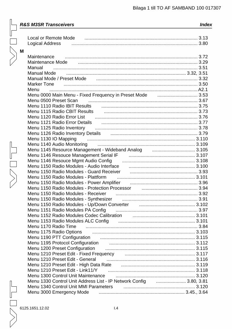
6125.1651.12.02 I.4
R&S M3SR Transceivers Index
Local or Remote Mode ....................................................................................... 3.13Logical Address ................................................................................................. 3.80
MMaintenance ...................................................................................................... 3.72Maintenance Mode ............................................................................................ 3.29Manual ............................................................................................................... 3.51Manual Mode ............................................................................................ 3.32, 3.51Manual Mode / Preset Mode .............................................................................. 3.32Marker Tone ....................................................................................................... 3.50Menu ..................................................................................................................A2.1Menu 0000 Main Menu - Fixed Frequency in Preset Mode ............................... 3.53Menu 0500 Preset Scan .................................................................................... 3.67Menu 1110 Radio IBIT Results .......................................................................... 3.75Menu 1115 Radio CBIT Results ........................................................................ 3.73Menu 1120 Radio Error List ............................................................................... 3.76Menu 1121 Radio Error Details .......................................................................... 3.77Menu 1125 Radio Inventory ............................................................................... 3.78Menu 1126 Radio Inventory Details ................................................................... 3.79Menu 1130 IO Mapping ................................................................................... 3.110Menu 1140 Audio Monitoring ........................................................................... 3.109Menu 1145 Resource Management - Wideband Analog ................................. 3.105Menu 1146 Resouce Management Serial IF ................................................... 3.107Menu 1146 Resouce Mgmt Audio Config ........................................................ 3.108Menu 1150 Radio Modules - Audio Interface ................................................... 3.100Menu 1150 Radio Modules - Guard Receiver .................................................... 3.93Menu 1150 Radio Modules - Plattform ............................................................ 3.101Menu 1150 Radio Modules - Power Amplifier .................................................... 3.96Menu 1150 Radio Modules - Protection Processor ........................................... 3.94Menu 1150 Radio Modules - Receiver ............................................................... 3.92Menu 1150 Radio Modules - Synthesizer .......................................................... 3.91Menu 1150 Radio Modules - Up/Down Converter ........................................... 3.102Menu 1151 Radio Modules PA Config ............................................................... 3.97Menu 1152 Radio Modules Codec Calibration ................................................ 3.101Menu 1153 Radio Modules ALC Config ........................................................... 3.101Menu 1170 Radio Time ...................................................................................... 3.84Menu 1175 Radio Options ............................................................................... 3.103Menu 1190 PTT Configuration ......................................................................... 3.115Menu 1195 Protocol Configuration .................................................................. 3.112Menu 1200 Preset Configuration ..................................................................... 3.115Menu 1210 Preset Edit - Fixed Frequency ...................................................... 3.117Menu 1210 Preset Edit - General .................................................................... 3.116Menu 1210 Preset Edit - High Data Rate ......................................................... 3.119Menu 1210 Preset Edit - Link11/Y ................................................................... 3.118Menu 1300 Control Unit Maintenance ............................................................. 3.120Menu 1330 Control Unit Address List - IP Network Config ....................... 3.80, 3.81Menu 1340 Control Unit MMI Parameters ....................................................... 3.120Menu 3000 Emergency Mode .................................................................. 3.45., 3.64
Bilaga 1 till TO AF SAMBAND 100 017307
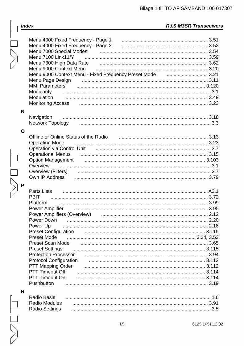
I.5 6125.1651.12.02
Index R&S M3SR Transceivers
Menu 4000 Fixed Frequency - Page 1 ............................................................... 3.51Menu 4000 Fixed Frequency - Page 2 ............................................................... 3.52Menu 7000 Special Modes ................................................................................ 3.54Menu 7100 Link11/Y .......................................................................................... 3.59Menu 7300 High Data Rate ............................................................................... 3.62Menu 9000 Context Menu .................................................................................. 3.20Menu 9000 Context Menu - Fixed Frequency Preset Mode .............................. 3.21Menu Page Design ............................................................................................ 3.11MMI Parameters .............................................................................................. 3.120Modularity ............................................................................................................ 3.1Modulation ......................................................................................................... 3.49Monitoring Access .............................................................................................. 3.23
NNavigation .......................................................................................................... 3.18Network Topology ................................................................................................ 3.3
OOffline or Online Status of the Radio ................................................................. 3.13Operating Mode ................................................................................................. 3.23Operation via Control Unit .................................................................................... 3.7Operational Menus ............................................................................................. 3.15Option Management ........................................................................................ 3.103Overview .............................................................................................................. 3.1Overview (Filters) ................................................................................................. 2.7Own IP Address ................................................................................................. 3.79
PParts Lists ..........................................................................................................A2.1PBIT ................................................................................................................... 3.72Platform .............................................................................................................. 3.99Power Amplifier .................................................................................................. 3.95Power Amplifiers (Overview) .............................................................................. 2.12Power Down ....................................................................................................... 2.20Power Up ........................................................................................................... 2.18Preset Configuration ........................................................................................ 3.115Preset Mode .............................................................................................. 3.34, 3.53Preset Scan Mode ............................................................................................. 3.65Preset Settings ................................................................................................. 3.115Protection Processor .......................................................................................... 3.94Protocol Configuration ..................................................................................... 3.112PTT Mapping Order ......................................................................................... 3.112PTT Timeout Off .............................................................................................. 3.114PTT Timeout On .............................................................................................. 3.114Pushbutton ......................................................................................................... 3.19
RRadio Basis .......................................................................................................... 1.6Radio Modules ................................................................................................... 3.91Radio Settings ...................................................................................................... 3.5
Bilaga 1 till TO AF SAMBAND 100 017307
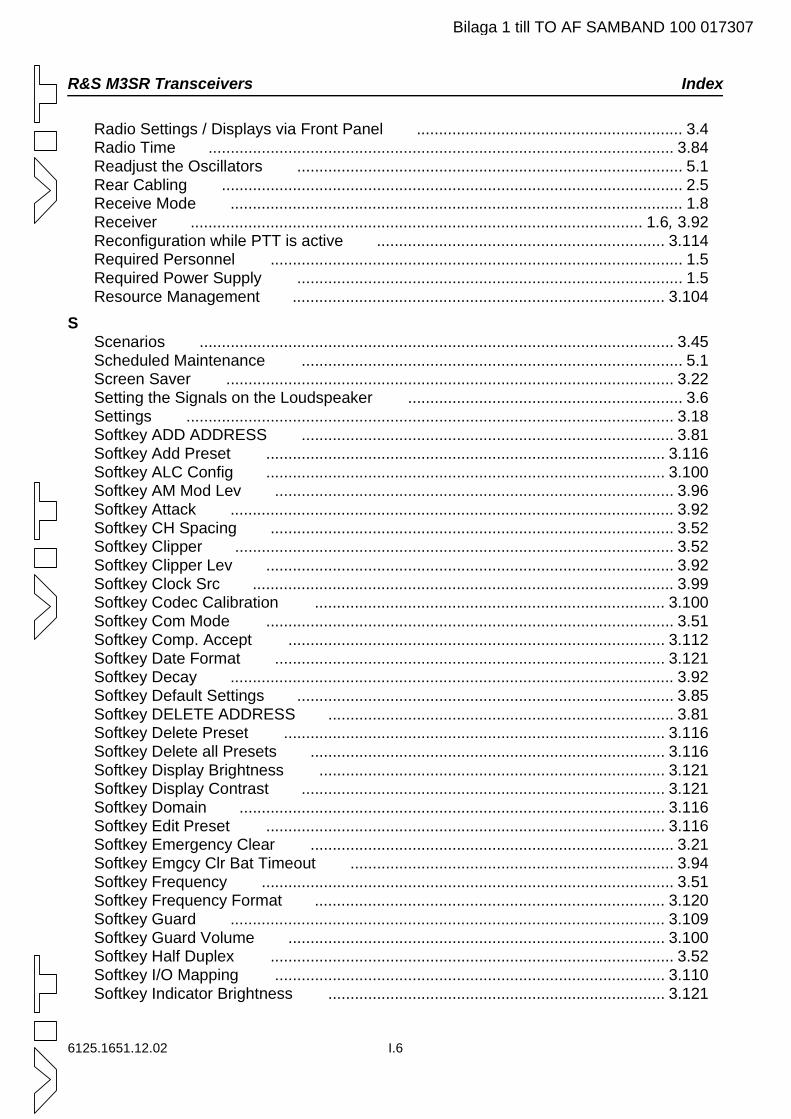
6125.1651.12.02 I.6
R&S M3SR Transceivers Index
Radio Settings / Displays via Front Panel ............................................................ 3.4Radio Time ......................................................................................................... 3.84Readjust the Oscillators ....................................................................................... 5.1Rear Cabling ........................................................................................................ 2.5Receive Mode ...................................................................................................... 1.8Receiver ...................................................................................................... 1.6, 3.92Reconfiguration while PTT is active ................................................................. 3.114Required Personnel ............................................................................................. 1.5Required Power Supply ....................................................................................... 1.5Resource Management .................................................................................... 3.104
SScenarios ........................................................................................................... 3.45Scheduled Maintenance ...................................................................................... 5.1Screen Saver ..................................................................................................... 3.22Setting the Signals on the Loudspeaker .............................................................. 3.6Settings .............................................................................................................. 3.18Softkey ADD ADDRESS .................................................................................... 3.81Softkey Add Preset .......................................................................................... 3.116Softkey ALC Config .......................................................................................... 3.100Softkey AM Mod Lev .......................................................................................... 3.96Softkey Attack .................................................................................................... 3.92Softkey CH Spacing ........................................................................................... 3.52Softkey Clipper ................................................................................................... 3.52Softkey Clipper Lev ............................................................................................ 3.92Softkey Clock Src ............................................................................................... 3.99Softkey Codec Calibration ............................................................................... 3.100Softkey Com Mode ............................................................................................ 3.51Softkey Comp. Accept ..................................................................................... 3.112Softkey Date Format ........................................................................................ 3.121Softkey Decay .................................................................................................... 3.92Softkey Default Settings ..................................................................................... 3.85Softkey DELETE ADDRESS .............................................................................. 3.81Softkey Delete Preset ...................................................................................... 3.116Softkey Delete all Presets ................................................................................ 3.116Softkey Display Brightness .............................................................................. 3.121Softkey Display Contrast .................................................................................. 3.121Softkey Domain ................................................................................................ 3.116Softkey Edit Preset .......................................................................................... 3.116Softkey Emergency Clear .................................................................................. 3.21Softkey Emgcy Clr Bat Timeout ......................................................................... 3.94Softkey Frequency ............................................................................................. 3.51Softkey Frequency Format ............................................................................... 3.120Softkey Guard .................................................................................................. 3.109Softkey Guard Volume ..................................................................................... 3.100Softkey Half Duplex ........................................................................................... 3.52Softkey I/O Mapping ........................................................................................ 3.110Softkey Indicator Brightness ............................................................................ 3.121
Bilaga 1 till TO AF SAMBAND 100 017307
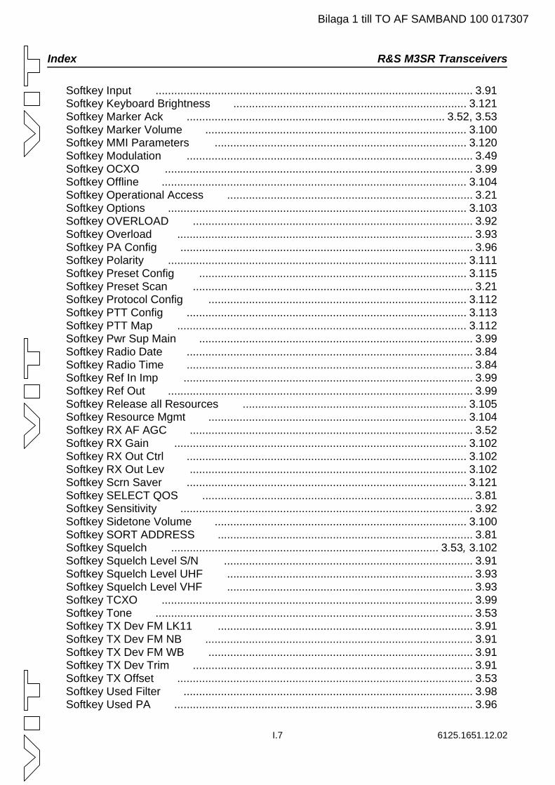
I.7 6125.1651.12.02
Index R&S M3SR Transceivers
Softkey Input ...................................................................................................... 3.91Softkey Keyboard Brightness ........................................................................... 3.121Softkey Marker Ack ................................................................................... 3.52, 3.53Softkey Marker Volume .................................................................................... 3.100Softkey MMI Parameters ................................................................................. 3.120Softkey Modulation ............................................................................................ 3.49Softkey OCXO ................................................................................................... 3.99Softkey Offline .................................................................................................. 3.104Softkey Operational Access ............................................................................... 3.21Softkey Options ................................................................................................ 3.103Softkey OVERLOAD .......................................................................................... 3.92Softkey Overload ............................................................................................... 3.93Softkey PA Config .............................................................................................. 3.96Softkey Polarity ................................................................................................ 3.111Softkey Preset Config ...................................................................................... 3.115Softkey Preset Scan .......................................................................................... 3.21Softkey Protocol Config ................................................................................... 3.112Softkey PTT Config .......................................................................................... 3.113Softkey PTT Map ............................................................................................. 3.112Softkey Pwr Sup Main ........................................................................................ 3.99Softkey Radio Date ............................................................................................ 3.84Softkey Radio Time ............................................................................................ 3.84Softkey Ref In Imp ............................................................................................. 3.99Softkey Ref Out .................................................................................................. 3.99Softkey Release all Resources ........................................................................ 3.105Softkey Resource Mgmt ................................................................................... 3.104Softkey RX AF AGC ........................................................................................... 3.52Softkey RX Gain .............................................................................................. 3.102Softkey RX Out Ctrl .......................................................................................... 3.102Softkey RX Out Lev ......................................................................................... 3.102Softkey Scrn Saver .......................................................................................... 3.121Softkey SELECT QOS ....................................................................................... 3.81Softkey Sensitivity .............................................................................................. 3.92Softkey Sidetone Volume ................................................................................. 3.100Softkey SORT ADDRESS .................................................................................. 3.81Softkey Squelch ...................................................................................... 3.53, 3.102Softkey Squelch Level S/N ................................................................................ 3.91Softkey Squelch Level UHF ............................................................................... 3.93Softkey Squelch Level VHF ............................................................................... 3.93Softkey TCXO .................................................................................................... 3.99Softkey Tone ...................................................................................................... 3.53Softkey TX Dev FM LK11 .................................................................................. 3.91Softkey TX Dev FM NB ...................................................................................... 3.91Softkey TX Dev FM WB ..................................................................................... 3.91Softkey TX Dev Trim .......................................................................................... 3.91Softkey TX Offset ............................................................................................... 3.53Softkey Used Filter ............................................................................................. 3.98Softkey Used PA ................................................................................................ 3.96
Bilaga 1 till TO AF SAMBAND 100 017307
6125.1651.12.02 I.8
R&S M3SR Transceivers Index
Softkey VCXO .................................................................................................... 3.99Softkeys ............................................................................................................. 3.10Software Package ................................................................................................ 1.8Special Key Combinations ................................................................................... 3.6Squelch .............................................................................................................. 3.49Status of Optional Access Rights ....................................................................... 3.13Subnet Mask ...................................................................................................... 3.80Supervisor Pin .................................................................................................... 3.31Suspend Mode ................................................................................................... 3.22Switching the Transceiver Off ............................................................................ 2.20Switching the Transceiver On ............................................................................ 2.18Synthesizer ................................................................................................. 1.6, 3.91
TTest Tone ........................................................................................................... 3.50Toggle Softkey ................................................................................................... 3.18Top View without Cover ....................................................................................... 1.7Touch up .............................................................................................................. 5.9Transmit Mode ..................................................................................................... 1.8Transmitter Unit ................................................................................................... 1.6Troubleshooting ................................................................................................. 3.72TX Offset ............................................................................................................ 3.49
UUHF Filter ............................................................................................................. 1.6Unpacking ............................................................................................................ 2.1Up/Down Converter ......................................................................................... 3.102User Information .................................................................................................. 1.1UX 4401 ........................................................................................................... 3.102
VValid Radio Operation and Communication Modes for Filters ............................. 2.8Valid Radio Operation and Communication Modes for Power Amplifiers .......... 2.12Voice Communication Mode .............................................................................. 3.48VT 4403 ............................................................................................................... 1.6
WWaveforms ......................................................................................................... 3.48Wideband Analog Communication Mode ........................................................... 3.48Wideband Digital Baseband Communication Mode ........................................... 3.48Wideband Digital Diphase Communication Mode .............................................. 3.48Wiring Diagram - e.g. FD 221 ............................................................................ 2.10Wiring Diagram - e.g. FD 430 ............................................................................ 2.17Wiring Diagram - e.g. VD 480L .......................................................................... 2.14Wiring Diagram - e.g. VU 220L .......................................................................... 2.15
Bilaga 1 till TO AF SAMBAND 100 017307
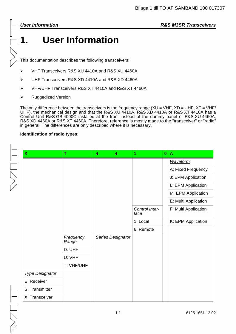
User Information R&S M3SR Transceivers
Bilaga 1 till TO AF SAMBAND 100 017307
1. User Information
This documentation describes the following transceivers:
VHF Transceivers R&S XU 4410A and R&S XU 4460A
UHF Transceivers R&S XD 4410A and R&S XD 4460A
VHF/UHF Transceivers R&S XT 4410A and R&S XT 4460A
Ruggedized Version
The only difference between the transceivers is the frequency range (XU = VHF, XD = UHF, XT = VHF/UHF), the mechanical design and that the R&S XU 4410A, R&S XD 4410A or R&S XT 4410A has a Control Unit R&S GB 4000C installed at the front instead of the dummy panel of R&S XU 4460A, R&S XD 4460A or R&S XT 4460A. Therefore, reference is mostly made to the "transceiver" or "radio" in general. The differences are only described where it is necessary.
Identification of radio types:
X T 4 4 1 0 A
Waveform
A: Fixed Frequency
J: EPM Application
L: EPM Application
M: EPM Application
E: Multi Application
Control Inter-face
F: Multi Application
1: Local K: EPM Application
6: Remote
Series DesignatorFrequency Range
D: UHF
U: VHF
T: VHF/UHF
Type Designator
E: Receiver
S: Transmitter
X: Transceiver
1.1 6125.1651.12.02
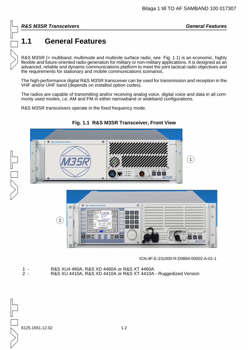
R&S M3SR Transceivers General Features
Bilaga 1 till TO AF SAMBAND 100 017307
1.1 General Features
R&S M3SR (= multiband, multimode and multirole surface radio, see Fig. 1.1) is an economic, highly flexible and future-oriented radio generation for military or non-military applications. It is designed as an advanced, reliable and dynamic communications platform to meet the joint tactical radio objectives and the requirements for stationary and mobile communications scenarios.
The high-performance digital R&S M3SR transceiver can be used for transmission and reception in the VHF and/or UHF band (depends on installed option codes).
The radios are capable of transmitting and/or receiving analog voice, digital voice and data in all com-monly used modes, i.e. AM and FM in either narrowband or wideband configurations.
R&S M3SR transceivers operate in the fixed frequency mode.
Fig. 1.1 R&S M3SR Transceiver, Front View
1 - R&S XU4 460A, R&S XD 4460A or R&S XT 4460A 2 - R&S XU 4410A, R&S XD 4410A or R&S XT 4410A - Ruggedized Version
ICN-4F-E-231000-R-D0894-00002-A-01-1
1
2
6125.1651.12.02 1.2
General benefits of the transceiver are: R&S M3SR Transceivers
Bilaga 1 till TO AF SAMBAND 100 017307
General benefits of the transceiver are:
Open-system architecture to customize for individual, initial or future needs.
Digital software programming of multiband, multifunction and multimode technology platform for advanced data waveforms, allowing flexible use and fast upgrading.
High modularity ("sliced radio") with a variety of internal modules and rear interfaces to meet the customer's operational and system requirements.
Flexible man-machine interface due to various local control panels and remote control units.
Simple data handling in networks compatible with standard interfaces (RS 232, LAN-Network).
High reliability (MTBF), short MTTR and efficient testability together with optimum maintaina-bility.
1.3 6125.1651.12.02
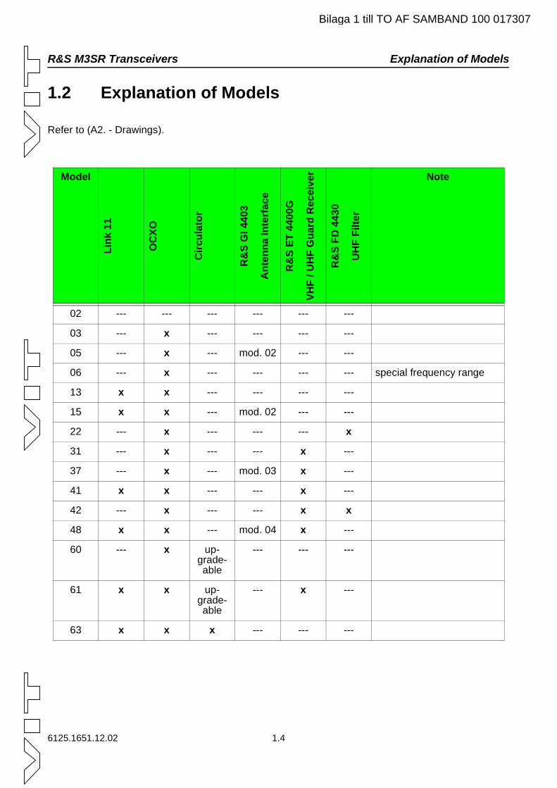
R&S M3SR Transceivers Explanation of Models
Bilaga 1 till TO AF SAMBAND 100 017307
1.2 Explanation of Models
Refer to (A2. - Drawings).
Model
Link
11
OC
XO
Circ
ulat
or
R&
SG
I440
3
Ant
enna
Inte
rfac
e
R&
SET
4400
G
VHF
/UH
FG
uard
Rec
eive
r
R&
SFD
4430
UH
FFi
lter
Note
02 --- --- --- --- --- ---
03 --- x --- --- --- ---
05 --- x --- mod. 02 --- ---
06 --- x --- --- --- --- special frequency range
13 x x --- --- --- ---
15 x x --- mod. 02 --- ---
22 --- x --- --- --- x
31 --- x --- --- x ---
37 --- x --- mod. 03 x ---
41 x x --- --- x ---
42 --- x --- --- x x
48 x x --- mod. 04 x ---
60 --- x up-grade-able
--- --- ---
61 x x up-grade-able
--- x ---
63 x x x --- --- ---
6125.1651.12.02 1.4
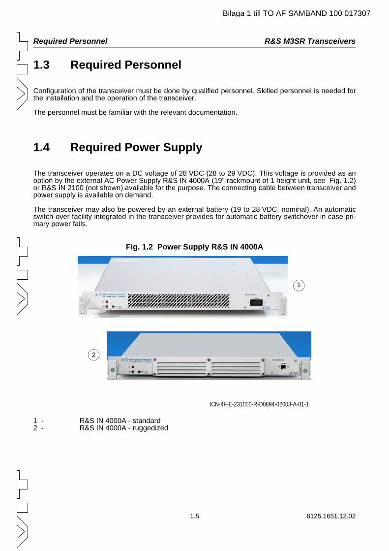
Required Personnel R&S M3SR Transceivers
1.5 6125.1651.12.02
1.3 Required Personnel
Configuration of the transceiver must be done by qualified personnel. Skilled personnel is needed forthe installation and the operation of the transceiver.
The personnel must be familiar with the relevant documentation.
1.4 Required Power Supply
The transceiver operates on a DC voltage of 28 VDC (28 to 29 VDC). This voltage is provided as anoption by the external AC Power Supply R&S IN 4000A (19" rackmount of 1 height unit, see Fig. 1.2)or R&S IN 2100 (not shown) available for the purpose. The connecting cable between transceiver andpower supply is available on demand.
The transceiver may also be powered by an external battery (19 to 28 VDC, nominal). An automaticswitch-over facility integrated in the transceiver provides for automatic battery switchover in case pri-mary power fails.
Fig. 1.2 Power Supply R&S IN 4000A
1 - R&S IN 4000A - standard2 - R&S IN 4000A - ruggedized
ICN-4F-E-231000-R-D0894-02003-A-01-1
1
2
Bilaga 1 till TO AF SAMBAND 100 017307
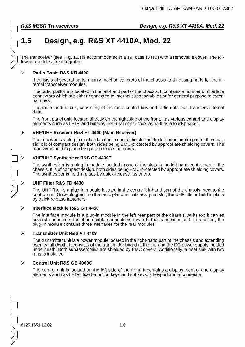
R&S M3SR Transceivers Design, e.g. R&S XT 4410A, Mod. 22
Bilaga 1 till TO AF SAMBAND 100 017307
1.5 Design, e.g. R&S XT 4410A, Mod. 22
The transceiver (see Fig. 1.3) is accommodated in a 19" case (3 HU) with a removable cover. The fol-lowing modules are integrated:
Radio Basis R&S KR 4400It consists of several parts, mainly mechanical parts of the chassis and housing parts for the in-ternal transceiver modules.The radio platform is located in the left-hand part of the chassis. It contains a number of interface connectors which are either connected to internal subassemblies or for general purpose to exter-nal ones.The radio module bus, consisting of the radio control bus and radio data bus, transfers internal data.The front panel unit, located directly on the right side of the front, has various control and display elements such as LEDs and buttons, external connectors as well as a loudspeaker.
VHF/UHF Receiver R&S ET 4400 (Main Receiver)The receiver is a plug-in module located in one of the slots in the left-hand centre part of the chas-sis. It is of compact design, both sides being EMC-protected by appropriate shielding covers. The receiver is held in place by quick-release fasteners.
VHF/UHF Synthesizer R&S GF 4400TThe synthesizer is a plug-in module located in one of the slots in the left-hand centre part of the chassis. It is of compact design, both sides being EMC-protected by appropriate shielding covers. The synthesizer is held in place by quick-release fasteners.
UHF Filter R&S FD 4430The UHF filter is a plug-in module located in the centre left-hand part of the chassis, next to the control unit. Once plugged into the radio platform in its assigned slot, the UHF filter is held in place by quick-release fasteners.
Interface Module R&S GH 4450The interface module is a plug-in module in the left rear part of the chassis. At its top it carries several connectors for ribbon-cable connections towards the transmitter unit. In addition, the plug-in module contains three interfaces for the rear modules.
Transmitter Unit R&S VT 4403The transmitter unit is a power module located in the right-hand part of the chassis and extending over its full depth. It consists of the transmitter board at the top and the DC power supply located underneath. Both subassemblies are shielded by EMC covers. Additionally, a heat sink with two fans is installed.
Control Unit R&S GB 4000CThe control unit is located on the left side of the front. It contains a display, control and display elements such as LEDs, fixed-function keys and softkeys, a keypad and a connector.
6125.1651.12.02 1.6
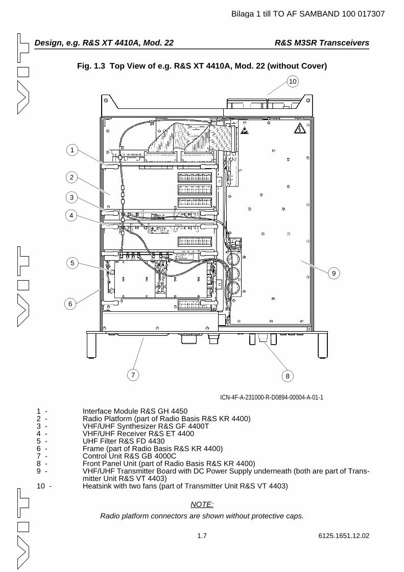
Design, e.g. R&S XT 4410A, Mod. 22 R&S M3SR Transceivers
Bilaga 1 till TO AF SAMBAND 100 017307
Fig. 1.3 Top View of e.g. R&S XT 4410A, Mod. 22 (without Cover)
1 - Interface Module R&S GH 4450 2 - Radio Platform (part of Radio Basis R&S KR 4400) 3 - VHF/UHF Synthesizer R&S GF 4400T 4 - VHF/UHF Receiver R&S ET 4400 5 - UHF Filter R&S FD 4430 6 - Frame (part of Radio Basis R&S KR 4400) 7 - Control Unit R&S GB 4000C 8 - Front Panel Unit (part of Radio Basis R&S KR 4400) 9 - VHF/UHF Transmitter Board with DC Power Supply underneath (both are part of Trans-
mitter Unit R&S VT 4403) 10 - Heatsink with two fans (part of Transmitter Unit R&S VT 4403)
NOTE:Radio platform connectors are shown without protective caps.
1
2
3
4
5
6
7 8
9
10
ICN-4F-A-231000-R-D0894-00004-A-01-1
1.7 6125.1651.12.02
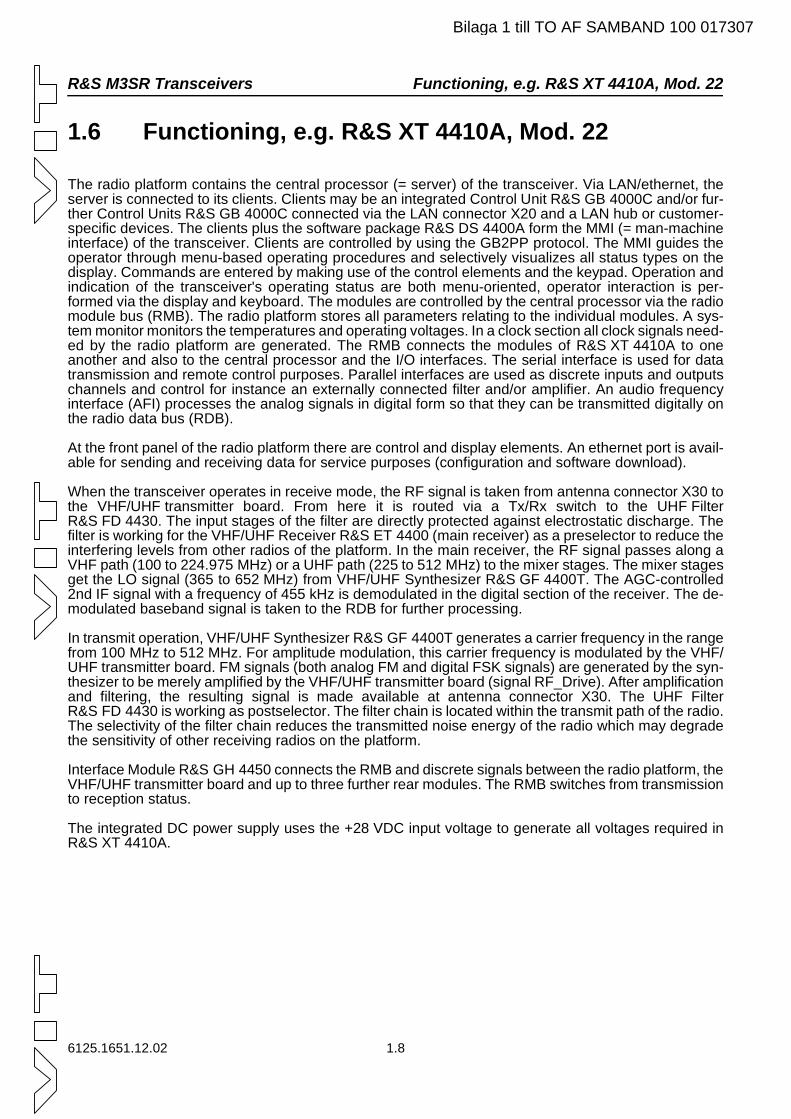
R&S M3SR Transceivers Functioning, e.g. R&S XT 4410A, Mod. 22
Bilaga 1 till TO AF SAMBAND 100 017307
1.6 Functioning, e.g. R&S XT 4410A, Mod. 22
The radio platform contains the central processor (= server) of the transceiver. Via LAN/ethernet, the server is connected to its clients. Clients may be an integrated Control Unit R&S GB 4000C and/or fur-ther Control Units R&S GB 4000C connected via the LAN connector X20 and a LAN hub or customer-specific devices. The clients plus the software package R&S DS 4400A form the MMI (= man-machine interface) of the transceiver. Clients are controlled by using the GB2PP protocol. The MMI guides the operator through menu-based operating procedures and selectively visualizes all status types on the display. Commands are entered by making use of the control elements and the keypad. Operation and indication of the transceiver's operating status are both menu-oriented, operator interaction is per-formed via the display and keyboard. The modules are controlled by the central processor via the radio module bus (RMB). The radio platform stores all parameters relating to the individual modules. A sys-tem monitor monitors the temperatures and operating voltages. In a clock section all clock signals need-ed by the radio platform are generated. The RMB connects the modules of R&S XT 4410A to one another and also to the central processor and the I/O interfaces. The serial interface is used for data transmission and remote control purposes. Parallel interfaces are used as discrete inputs and outputs channels and control for instance an externally connected filter and/or amplifier. An audio frequency interface (AFI) processes the analog signals in digital form so that they can be transmitted digitally on the radio data bus (RDB).
At the front panel of the radio platform there are control and display elements. An ethernet port is avail-able for sending and receiving data for service purposes (configuration and software download).
When the transceiver operates in receive mode, the RF signal is taken from antenna connector X30 to the VHF/UHF transmitter board. From here it is routed via a Tx/Rx switch to the UHF Filter R&S FD 4430. The input stages of the filter are directly protected against electrostatic discharge. The filter is working for the VHF/UHF Receiver R&S ET 4400 (main receiver) as a preselector to reduce the interfering levels from other radios of the platform. In the main receiver, the RF signal passes along a VHF path (100 to 224.975 MHz) or a UHF path (225 to 512 MHz) to the mixer stages. The mixer stages get the LO signal (365 to 652 MHz) from VHF/UHF Synthesizer R&S GF 4400T. The AGC-controlled 2nd IF signal with a frequency of 455 kHz is demodulated in the digital section of the receiver. The de-modulated baseband signal is taken to the RDB for further processing.
In transmit operation, VHF/UHF Synthesizer R&S GF 4400T generates a carrier frequency in the range from 100 MHz to 512 MHz. For amplitude modulation, this carrier frequency is modulated by the VHF/UHF transmitter board. FM signals (both analog FM and digital FSK signals) are generated by the syn-thesizer to be merely amplified by the VHF/UHF transmitter board (signal RF_Drive). After amplification and filtering, the resulting signal is made available at antenna connector X30. The UHF Filter R&S FD 4430 is working as postselector. The filter chain is located within the transmit path of the radio. The selectivity of the filter chain reduces the transmitted noise energy of the radio which may degrade the sensitivity of other receiving radios on the platform.
Interface Module R&S GH 4450 connects the RMB and discrete signals between the radio platform, the VHF/UHF transmitter board and up to three further rear modules. The RMB switches from transmission to reception status.
The integrated DC power supply uses the +28 VDC input voltage to generate all voltages required in R&S XT 4410A.
6125.1651.12.02 1.8
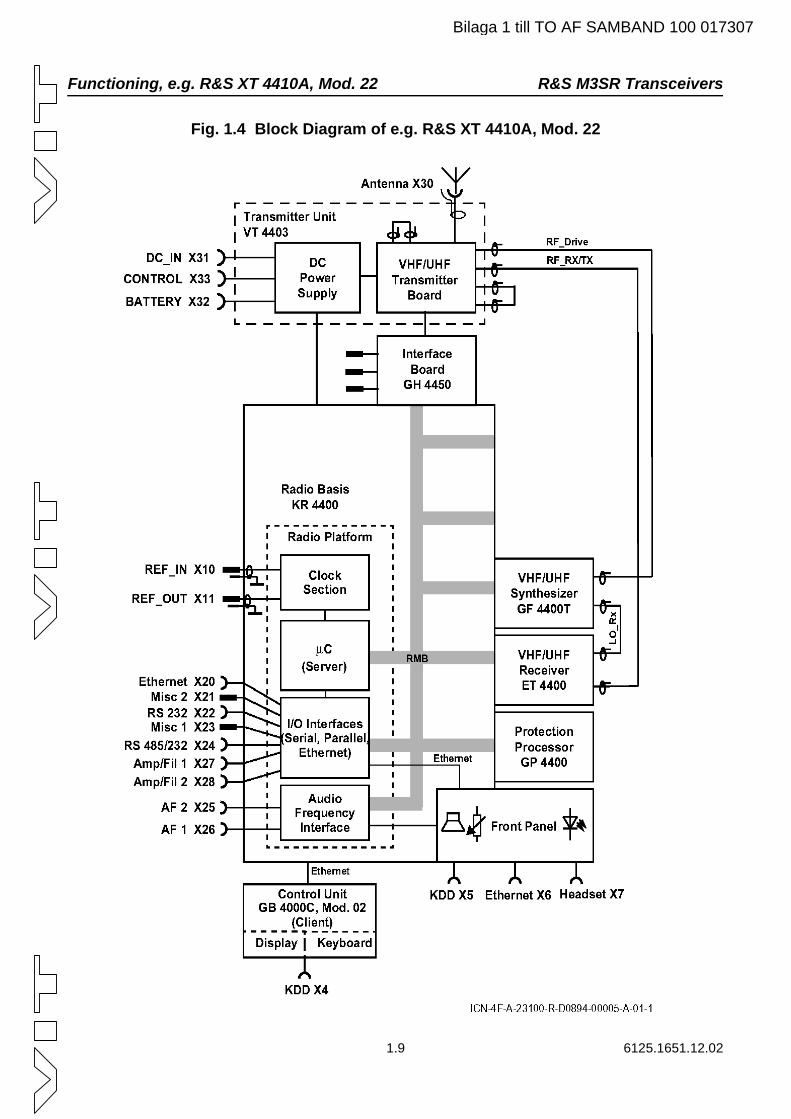
Functioning, e.g. R&S XT 4410A, Mod. 22 R&S M3SR Transceivers
Bilaga 1 till TO AF SAMBAND 100 017307
Fig. 1.4 Block Diagram of e.g. R&S XT 4410A, Mod. 22
1.9 6125.1651.12.02
R&S M3SR Transceivers General Data
Bilaga 1 till TO AF SAMBAND 100 017307
1.7 General Data
Refer to A2. - Drawings
1.8 Recommended Accessories
Refer to A2. - Drawings.
6125.1651.12.02 1.10
Preparation for Use R&S M3SR Transceivers
2.1 6125.1651.12.02
2. Preparation for Use
2.1 R&S M3SR - Unpacking
After delivery, perform the following steps:
1 Unpack the transceiver.
2 Check if the delivery (transceiver and accessories) is complete by comparing it to the delivery note.
3 Check the delivery for transport damage.
4 If you find any damage, contact the shipping agent immediately.
5 Keep the package for later use, in case the tranceiver must be sent to a Rohde & Schwarz rep-resentative for servicing.
Bilaga 1 till TO AF SAMBAND 100 017307
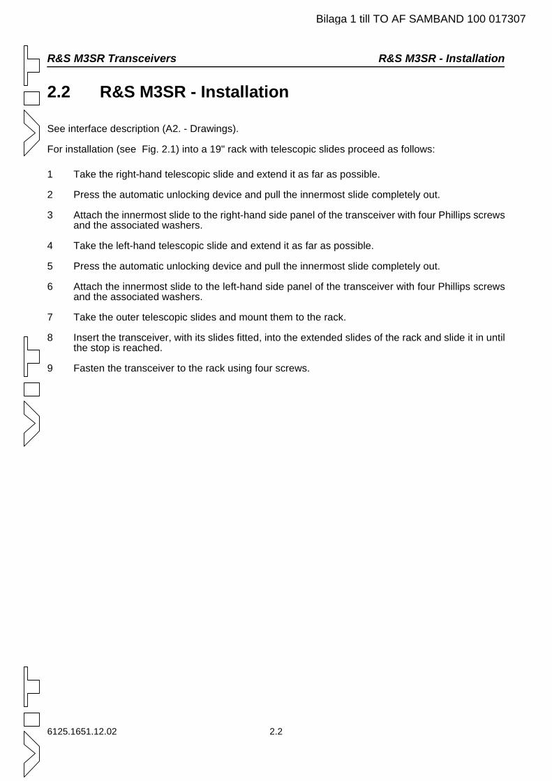
R&S M3SR Transceivers R&S M3SR - Installation
Bilaga 1 till TO AF SAMBAND 100 017307
2.2 R&S M3SR - Installation
See interface description (A2. - Drawings).
For installation (see Fig. 2.1) into a 19" rack with telescopic slides proceed as follows:
1 Take the right-hand telescopic slide and extend it as far as possible.
2 Press the automatic unlocking device and pull the innermost slide completely out.
3 Attach the innermost slide to the right-hand side panel of the transceiver with four Phillips screws and the associated washers.
4 Take the left-hand telescopic slide and extend it as far as possible.
5 Press the automatic unlocking device and pull the innermost slide completely out.
6 Attach the innermost slide to the left-hand side panel of the transceiver with four Phillips screws and the associated washers.
7 Take the outer telescopic slides and mount them to the rack.
8 Insert the transceiver, with its slides fitted, into the extended slides of the rack and slide it in until the stop is reached.
9 Fasten the transceiver to the rack using four screws.
6125.1651.12.02 2.2
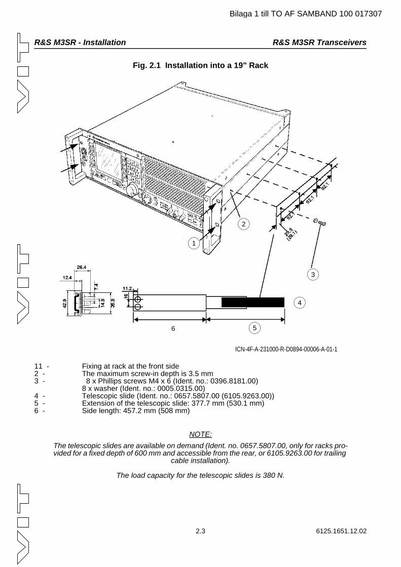
R&S M3SR - Installation R&S M3SR Transceivers
Bilaga 1 till TO AF SAMBAND 100 017307
Fig. 2.1 Installation into a 19" Rack
11 - Fixing at rack at the front side2 - The maximum screw-in depth is 3.5 mm3 - 8 x Phillips screws M4 x 6 (Ident. no.: 0396.8181.00)
8 x washer (Ident. no.: 0005.0315.00)4 - Telescopic slide (Ident. no.: 0657.5807.00 (6105.9263.00))5 - Extension of the telescopic slide: 377.7 mm (530.1 mm)6 - Side length: 457.2 mm (508 mm)
NOTE:The telescopic slides are available on demand (Ident. no. 0657.5807.00, only for racks pro-vided for a fixed depth of 600 mm and accessible from the rear, or 6105.9263.00 for trailing
cable installation).
The load capacity for the telescopic slides is 380 N.
1
2
3
4
56
ICN-4F-A-231000-R-D0894-00006-A-01-1
2.3 6125.1651.12.02
R&S M3SR Transceivers R&S M3SR - Connect Procedures
Bilaga 1 till TO AF SAMBAND 100 017307
2.3 R&S M3SR - Connect Procedures
C A U T I O N
Connect the mains cable only after all other wiring has been made.
Keep off the antenna while transmission is in progress. During transmission danger-ous high voltages and electromagnetic fields are produced. Respect the instructions of DIN VDE 0848-2 and the ICNIRP (International Commission on Non-Ionizing Radi-
ation Protection) Guidelines for non-ionizing emission (see www.icnirp.org).
NOTE:For detailed information on connectors and contact assignment see the interface descrip-
tion (A2. - Drawings).
6125.1651.12.02 2.4

R&S M3SR - Connect Procedures R&S M3SR Transceivers
Bilaga 1 till TO AF SAMBAND 100 017307
2.3.1 Basic Connection
Rear Side
Necessary cabling at the rear side:
Fig. 2.2 Rear Cabling
11 - Connector X30 to antenna2 - Connector Ground3 - LAN connector X20 to remote control unit (required for radios without built-in control unit)4 - Connector X31 to external power supply (e.g. R&S IN 4000A or R&S IN 2100)5 - Connector X32 to external battery
NOTE:The cable between connector X31 DC IN (part of radio) and the relevant connector of the
power supply is available on demand.
R&S IN 4000A: 6105.5639.xx (xx = 05: 0.5 m, 10: 1.0 m, 25: 2.5 m)
R&S IN 2100: 6120.3956.02
The connector X32 is an optional battery connection (19 to 28 VDC, ≤ 25 A). In case of a power supply failure the system switches automatically to this battery supply.
ICN-4F-C-231000-R-D0894-00007-A-02-1
1 2
345
2.5 6125.1651.12.02
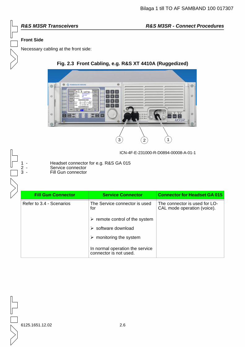
R&S M3SR Transceivers R&S M3SR - Connect Procedures
Bilaga 1 till TO AF SAMBAND 100 017307
Front Side
Necessary cabling at the front side:
Fig. 2.3 Front Cabling, e.g. R&S XT 4410A (Ruggedized)
1 - Headset connector for e.g. R&S GA 0152 - Service connector3 - Fill Gun connector
Fill Gun Connector Service Connector Connector for Headset GA 015
Refer to 3.4 - Scenarios The Service connector is used for
remote control of the system
software download
monitoring the system
In normal operation the service connector is not used.
The connector is used for LO-CAL mode operation (voice).
ICN-4F-E-231000-R-D0894-00008-A-01-1
123
6125.1651.12.02 2.6
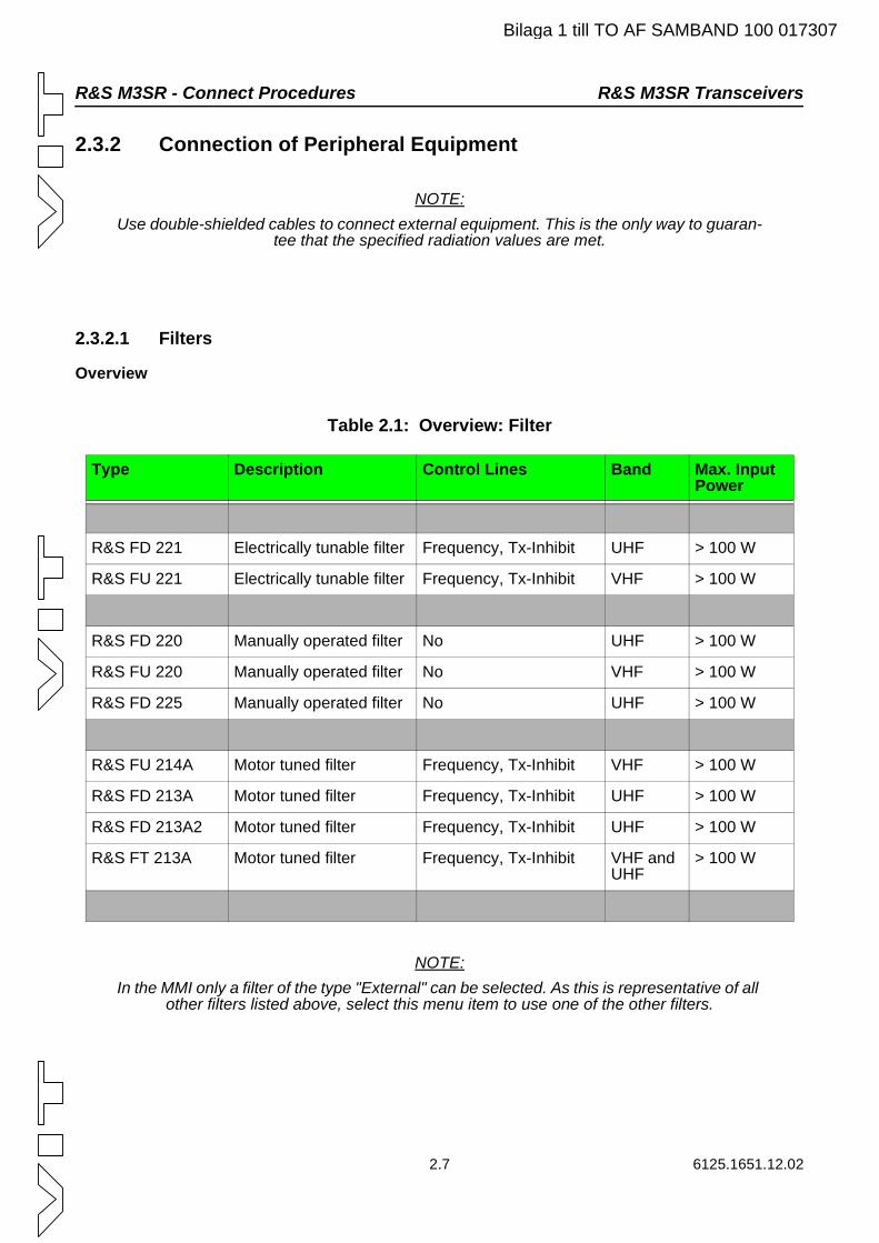
R&S M3SR - Connect Procedures R&S M3SR Transceivers
Bilaga 1 till TO AF SAMBAND 100 017307
2.3.2 Connection of Peripheral Equipment
NOTE:Use double-shielded cables to connect external equipment. This is the only way to guaran-
tee that the specified radiation values are met.
2.3.2.1 Filters
Overview
Table 2.1: Overview: Filter
NOTE:In the MMI only a filter of the type "External" can be selected. As this is representative of all
other filters listed above, select this menu item to use one of the other filters.
Type Description Control Lines Band Max. Input Power
R&S FD 221 Electrically tunable filter Frequency, Tx-Inhibit UHF > 100 W
R&S FU 221 Electrically tunable filter Frequency, Tx-Inhibit VHF > 100 W
R&S FD 220 Manually operated filter No UHF > 100 W
R&S FU 220 Manually operated filter No VHF > 100 W
R&S FD 225 Manually operated filter No UHF > 100 W
R&S FU 214A Motor tuned filter Frequency, Tx-Inhibit VHF > 100 W
R&S FD 213A Motor tuned filter Frequency, Tx-Inhibit UHF > 100 W
R&S FD 213A2 Motor tuned filter Frequency, Tx-Inhibit UHF > 100 W
R&S FT 213A Motor tuned filter Frequency, Tx-Inhibit VHF and UHF
> 100 W
2.7 6125.1651.12.02
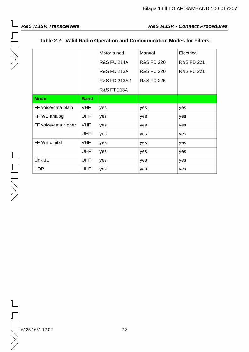
R&S M3SR Transceivers R&S M3SR - Connect Procedures
Bilaga 1 till TO AF SAMBAND 100 017307
Table 2.2: Valid Radio Operation and Communication Modes for Filters
Motor tuned
R&S FU 214A
R&S FD 213A
R&S FD 213A2
R&S FT 213A
Manual
R&S FD 220
R&S FU 220
R&S FD 225
Electrical
R&S FD 221
R&S FU 221
Mode Band
FF voice/data plain VHF yes yes yes
FF WB analog UHF yes yes yes
FF voice/data cipher VHF yes yes yes
UHF yes yes yes
FF WB digital VHF yes yes yes
UHF yes yes yes
Link 11 UHF yes yes yes
HDR UHF yes yes yes
6125.1651.12.02 2.8
R&S M3SR - Connect Procedures R&S M3SR Transceivers
Bilaga 1 till TO AF SAMBAND 100 017307
Configuration
No configuration of the R&S M3SR transceiver is necessary because frequency control is done auto-matically.
No protection is built in against wrong frequency commands to the filter.
A filter has 20 seconds to perform a commanded frequency change. Otherwise, the R&S M3SR soft-ware generates an error message.
For further system aspects with frequency hopping applications, please use the R&S M3SR control pin 'Relay_1' = '~ECCM' = default on X21.1 (and e.g. R&S ZS 402 for external RF bypass), if necessary.
The transceiver controls the output 'Relay_1' like this:
In FF = High
In Link 11 = High
HDR = High
2.9 6125.1651.12.02
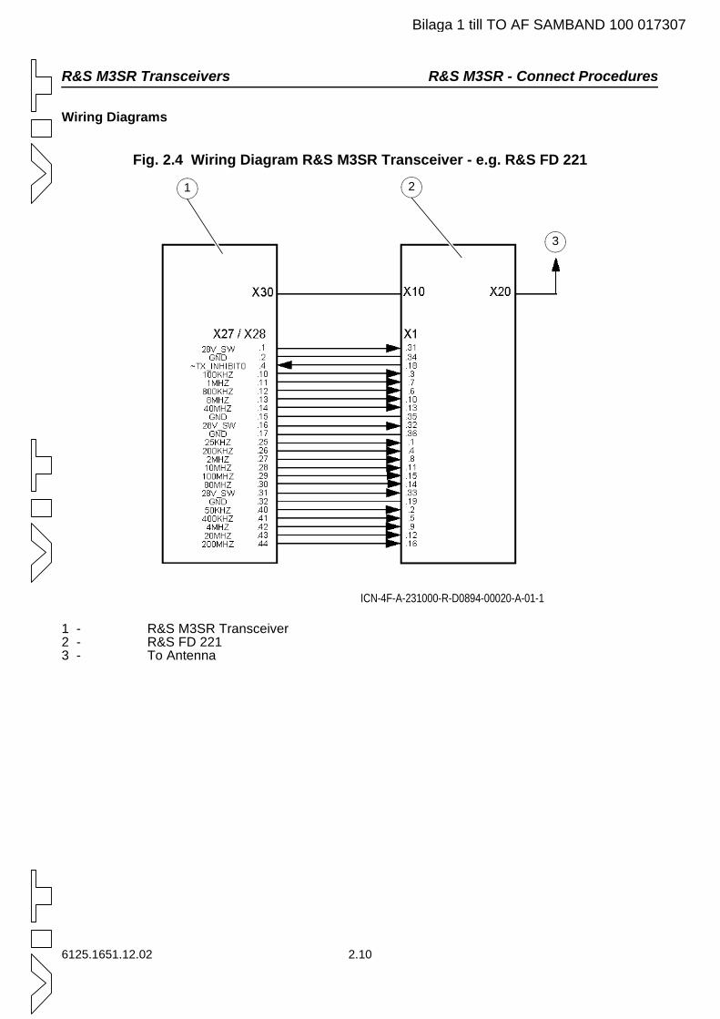
R&S M3SR Transceivers R&S M3SR - Connect Procedures
Bilaga 1 till TO AF SAMBAND 100 017307
Wiring Diagrams
Fig. 2.4 Wiring Diagram R&S M3SR Transceiver - e.g. R&S FD 221
1 - R&S M3SR Transceiver2 - R&S FD 2213 - To Antenna
ICN-4F-A-231000-R-D0894-00020-A-01-1
1 2
3
6125.1651.12.02 2.10
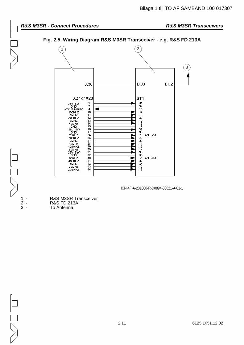
R&S M3SR - Connect Procedures R&S M3SR Transceivers
Bilaga 1 till TO AF SAMBAND 100 017307
Fig. 2.5 Wiring Diagram R&S M3SR Transceiver - e.g. R&S FD 213A
1 - R&S M3SR Transceiver2 - R&S FD 213A3 - To Antenna
ICN-4F-A-231000-R-D0894-00021-A-01-1
1 2
3
2.11 6125.1651.12.02
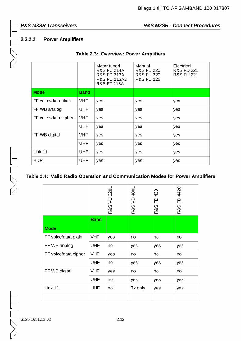
R&S M3SR Transceivers R&S M3SR - Connect Procedures
Bilaga 1 till TO AF SAMBAND 100 017307
2.3.2.2 Power Amplifiers
Table 2.3: Overview: Power Amplifiers
Table 2.4: Valid Radio Operation and Communication Modes for Power Amplifiers
Motor tunedR&S FU 214AR&S FD 213AR&S FD 213A2R&S FT 213A
ManualR&S FD 220R&S FU 220R&S FD 225
ElectricalR&S FD 221R&S FU 221
Mode Band
FF voice/data plain VHF yes yes yes
FF WB analog UHF yes yes yes
FF voice/data cipher VHF yes yes yes
UHF yes yes yes
FF WB digital VHF yes yes yes
UHF yes yes yes
Link 11 UHF yes yes yes
HDR UHF yes yes yes
R&
SV
U22
0L
R&
SV
D48
0L
R&
SFD
430
R&
SFD
4420
Mode
Band
FF voice/data plain VHF yes no no no
FF WB analog UHF no yes yes yes
FF voice/data cipher VHF yes no no no
UHF no yes yes yes
FF WB digital VHF yes no no no
UHF no yes yes yes
Link 11 UHF no Tx only yes yes
6125.1651.12.02 2.12
R&S M3SR - Connect Procedures R&S M3SR Transceivers
Bilaga 1 till TO AF SAMBAND 100 017307
Additional information for R&S VD 480L:
In Link 11 mode the amplifier is permanently set to transmission (= Tx only), so no reception is possible. If, however, the amplifier needs to be operated in Link 11, connect a separate Rx antenna to the trans-ceiver.
Configuration
C A U T I O N
The R&S M3SR transceiver cannot automatically detect a connected amplifier. Therefore the transceiver must be configured before putting it into operation. Pro-
ceed with extreme care when configuring the transceiver.
Wrong transceiver configuration may damage the used peripheral amplifier!
1 Press softkey MAINT (part of menu 0000 Main Menu).
2 Press softkey RADIO MAINT (part of menu 1000 Maintenance).
3 Press softkey RADIO MODULES (part of menu 1100 Radio Maintenance).
4 Select the folder POWER AMPLIFIER (part of menu 1150 Radio Modules).
5 Press softkey USED PA.
6 Enter the Maint PIN via the numerical keypad.
7 Press ENT key.
8 Select the desired power amplifier.
Here the amplifier to be operated with the transceiver is selected. Only one amplifier can be con-nected at a time. If no amplifier is connected, select INTERNAL.
9 Press ENT key.
10 Press softkey PA CONFIG.
11 Select the folder of the amplifier selected in step 8. Here the driving power for the power levels Low, Med, High for AM and FM is defined. The driving power indirectly determines the output power of the amplifier (for gain refer to data sheet of relevant amplifier) and thus the transmission coverage with this amplifier type. Only R&S VD 480L/R&S VU 220L:
By means of the On/Off switch the user determines at which power level the external amplifier is to be connected into line or whether it is bypassed.
2.13 6125.1651.12.02
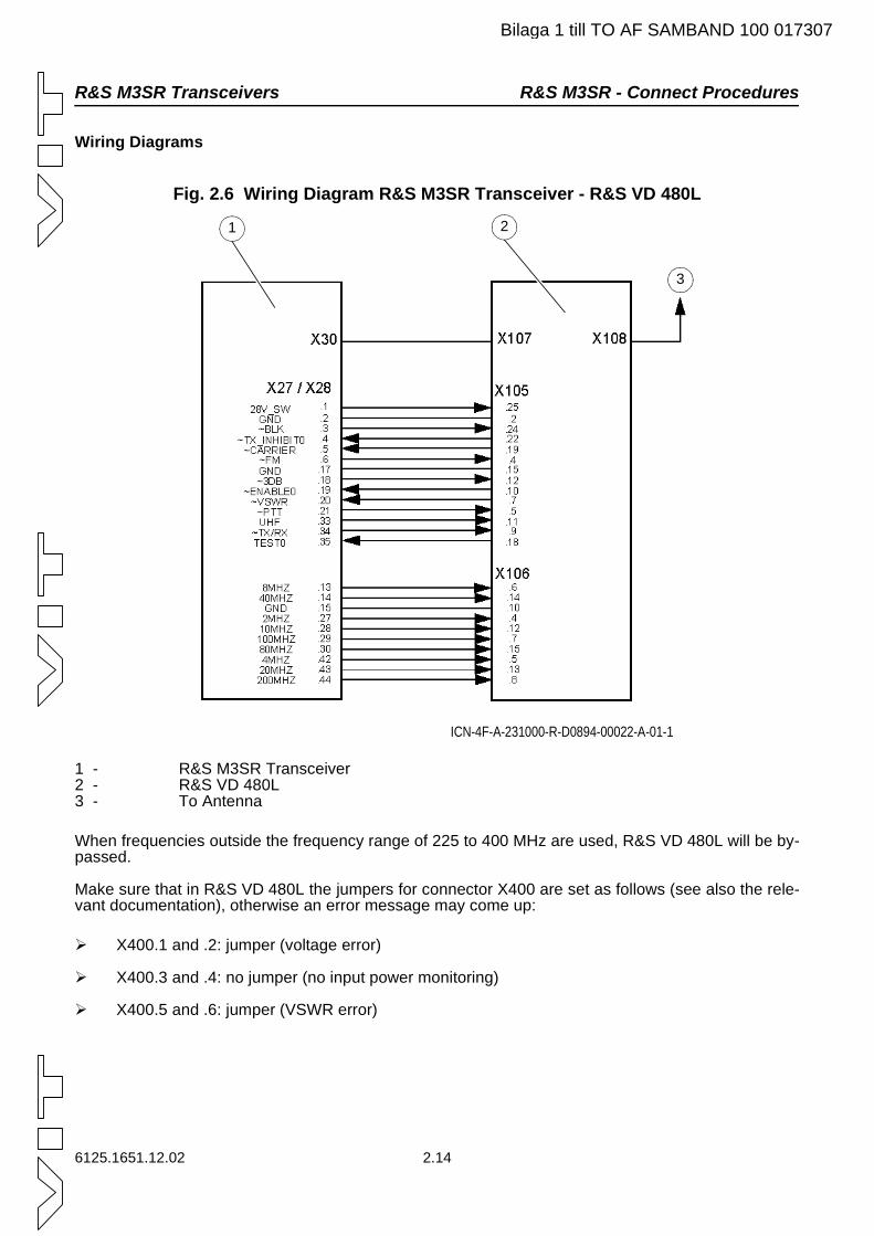
R&S M3SR Transceivers R&S M3SR - Connect Procedures
Bilaga 1 till TO AF SAMBAND 100 017307
Wiring Diagrams
Fig. 2.6 Wiring Diagram R&S M3SR Transceiver - R&S VD 480L
1 - R&S M3SR Transceiver2 - R&S VD 480L3 - To Antenna
When frequencies outside the frequency range of 225 to 400 MHz are used, R&S VD 480L will be by-passed.
Make sure that in R&S VD 480L the jumpers for connector X400 are set as follows (see also the rele-vant documentation), otherwise an error message may come up:
X400.1 and .2: jumper (voltage error)
X400.3 and .4: no jumper (no input power monitoring)
X400.5 and .6: jumper (VSWR error)
ICN-4F-A-231000-R-D0894-00022-A-01-1
1 2
3
6125.1651.12.02 2.14
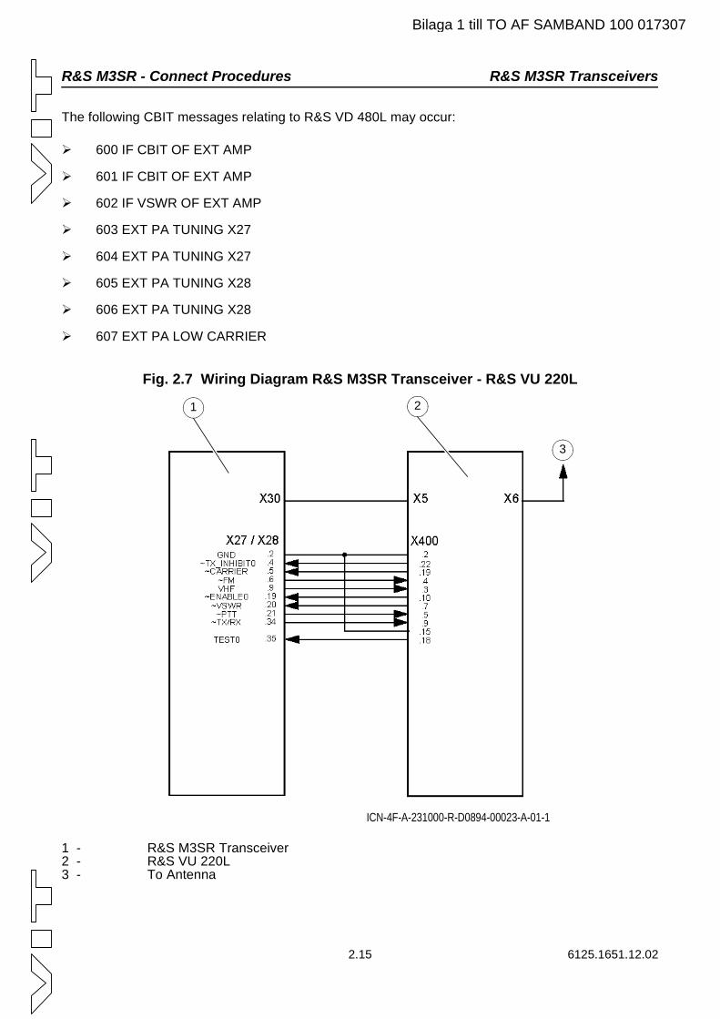
R&S M3SR - Connect Procedures R&S M3SR Transceivers
Bilaga 1 till TO AF SAMBAND 100 017307
The following CBIT messages relating to R&S VD 480L may occur:
600 IF CBIT OF EXT AMP
601 IF CBIT OF EXT AMP
602 IF VSWR OF EXT AMP
603 EXT PA TUNING X27
604 EXT PA TUNING X27
605 EXT PA TUNING X28
606 EXT PA TUNING X28
607 EXT PA LOW CARRIER
Fig. 2.7 Wiring Diagram R&S M3SR Transceiver - R&S VU 220L
1 - R&S M3SR Transceiver2 - R&S VU 220L3 - To Antenna
ICN-4F-A-231000-R-D0894-00023-A-01-1
1 2
3
2.15 6125.1651.12.02
R&S M3SR Transceivers R&S M3SR - Connect Procedures
Bilaga 1 till TO AF SAMBAND 100 017307
When frequencies outside the band of 118 to 144 MHz are used, a protection circuit prevents the trans-mitter from being activated. That is, when an amplifier is connected, transmission outside this frequency
band is impossible. When the protection is active, the central area shows the symbol in the 'Pow-er' line.
To transmit outside this frequency band the following measure must be taken:
Disconnect transceiver from power amplifier.
In menu 1150 Radio Modules press softkey USED PA and select INTERNAL.
The following CBIT messages relating to R&S VU 220L may occur:
600 IF CBIT OF EXT AMP
601 IF CBIT OF EXT AMP
602 IF VSWR OF EXT AMP
603 EXT PA TUNING X27
604 EXT PA TUNING X27
605 EXT PA TUNING X28
606 EXT PA TUNING X28
607 EXT PA LOW CARRIER
6125.1651.12.02 2.16
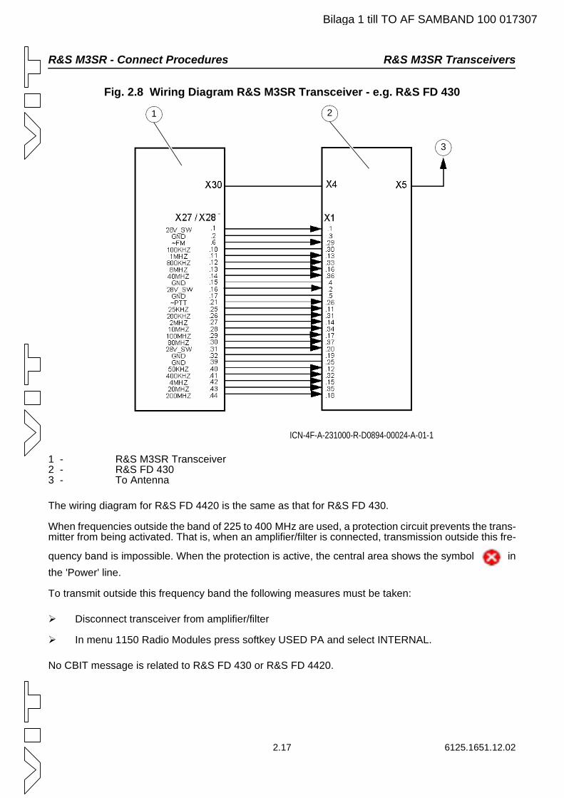
R&S M3SR - Connect Procedures R&S M3SR Transceivers
Bilaga 1 till TO AF SAMBAND 100 017307
Fig. 2.8 Wiring Diagram R&S M3SR Transceiver - e.g. R&S FD 430
1 - R&S M3SR Transceiver2 - R&S FD 4303 - To Antenna
The wiring diagram for R&S FD 4420 is the same as that for R&S FD 430.
When frequencies outside the band of 225 to 400 MHz are used, a protection circuit prevents the trans-mitter from being activated. That is, when an amplifier/filter is connected, transmission outside this fre-
quency band is impossible. When the protection is active, the central area shows the symbol in the 'Power' line.
To transmit outside this frequency band the following measures must be taken:
Disconnect transceiver from amplifier/filter
In menu 1150 Radio Modules press softkey USED PA and select INTERNAL.
No CBIT message is related to R&S FD 430 or R&S FD 4420.
ICN-4F-A-231000-R-D0894-00024-A-01-1
1 2
3
2.17 6125.1651.12.02
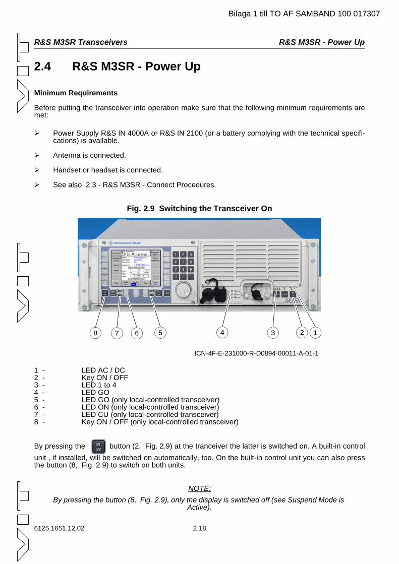
R&S M3SR Transceivers R&S M3SR - Power Up
Bilaga 1 till TO AF SAMBAND 100 017307
2.4 R&S M3SR - Power Up
Minimum Requirements
Before putting the transceiver into operation make sure that the following minimum requirements are met:
Power Supply R&S IN 4000A or R&S IN 2100 (or a battery complying with the technical specifi-cations) is available.
Antenna is connected.
Handset or headset is connected.
See also 2.3 - R&S M3SR - Connect Procedures.
Fig. 2.9 Switching the Transceiver On
1 - LED AC / DC2 - Key ON / OFF3 - LED 1 to 44 - LED GO5 - LED GO (only local-controlled transceiver)6 - LED ON (only local-controlled transceiver)7 - LED CU (only local-controlled transceiver)8 - Key ON / OFF (only local-controlled transceiver)
By pressing the button (2, Fig. 2.9) at the tranceiver the latter is switched on. A built-in control unit , if installed, will be switched on automatically, too. On the built-in control unit you can also press the button (8, Fig. 2.9) to switch on both units.
NOTE:By pressing the button (8, Fig. 2.9), only the display is switched off (see Suspend Mode is
Active).
ICN-4F-E-231000-R-D0894-00011-A-01-1
1234578 6
6125.1651.12.02 2.18
R&S M3SR - Power Up R&S M3SR Transceivers
Bilaga 1 till TO AF SAMBAND 100 017307
The following LEDs are illuminated to indicate readiness for operation:
CU (7, Fig. 2.9): control unit ok
ON (6, Fig. 2.9): control unit ready for operation
GO (4 and 5, Fig. 2.9): transceiver ok
1 (3, Fig. 2.9): indicates which signal is being output via the loudspeaker
AC/DC (1, Fig. 2.9): power available
The last displayed menu is shown again (only local-controlled transceiver).
NOTE:If the PBIT (automatic power-on built-in test) during the startup of the system dectects an
error, perform an IBIT to get more information.
If the LED 1 remains dark, press the SELECT button.
2.19 6125.1651.12.02
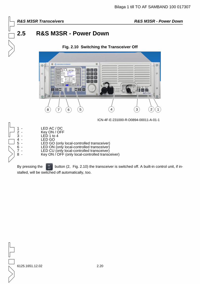
R&S M3SR Transceivers R&S M3SR - Power Down
6125.1651.12.02 2.20
2.5 R&S M3SR - Power Down
Fig. 2.10 Switching the Transceiver Off
1 - LED AC / DC2 - Key ON / OFF3 - LED 1 to 44 - LED GO5 - LED GO (only local-controlled transceiver)6 - LED ON (only local-controlled transceiver)7 - LED CU (only local-controlled transceiver)8 - Key ON / OFF (only local-controlled transceiver)
By pressing the button (2, Fig. 2.10) the transceiver is switched off. A built-in control unit, if in-stalled, will be switched off automatically, too.
ICN-4F-E-231000-R-D0894-00011-A-01-1
1234578 6
Bilaga 1 till TO AF SAMBAND 100 017307
Operation R&S M3SR Transceivers
Bilaga 1 till TO AF SAMBAND 100 017307
3. Operation
3.1 Overview
R&S M3SR (multiband, multimode, multirole surface radio) is a new software radio generation. The pa-rameters of the radio are set via the man-machine interface (MMI). This means that the radios can be reprogrammed regarding waveforms and external interfaces. Modules like a guard receiver as well as a protection processor module can be integrated. Each module has an integrated firmware. Therefore the radio has an open system architecture that allows future updates.
Additional Options and Modules
The possibility of this radio generation to enhance functionality by loading new application software is an outstanding new feature. This requires a certain expansion stage regarding the hardware. If it is nec-essary, new hardware modules can be integrated.
Device settings can be made locally via the menus of the local control panel (CP) or via a remote control unit (CU) or via remote control commands (GB2PP protocol) via LAN. Software and hardware options are available to provide the radio units with additional EPM waveforms.
Frequency Ranges of Basic Units
The frequency ranges depend on installed option codes.
Modularity
All R&S M3SR units are based on the uniform Radio Basis R&S KR 4400, which consists of a mechan-ical frame, the radio platform and the audio front panel. The radio platform itself processes the AF sig-nals, independently of the transmitter and the receiver modules. Depending on the desired radio equipment configuration, radio modules such as main receiver, synthesizer or guard receiver are in-serted. A transmitter module with an integrated DC/DC power supply is built in. Six free slots for user-specific plug-in cards are integrated in the rear part of the unit.
Local / Remote Application
The radio is delivered by default without an integrated control unit. The local Control Unit R&S GB 4000C is available as an option.
The radio can be completely remote-configured and controlled for example with the R&S GB 4000C. There is no limitation for remote control. In local mode the radio can be used as a tabletop unit as a voice radio. Then it is controlled by the integrated control unit.
3.1 6125.1651.12.02
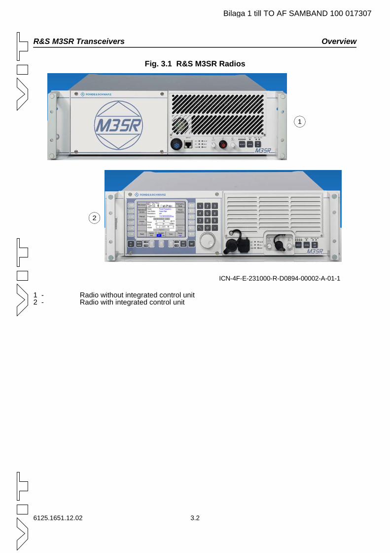
R&S M3SR Transceivers Overview
Bilaga 1 till TO AF SAMBAND 100 017307
Fig. 3.1 R&S M3SR Radios
1 - Radio without integrated control unit2 - Radio with integrated control unit
ICN-4F-E-231000-R-D0894-00002-A-01-1
1
2
6125.1651.12.02 3.2
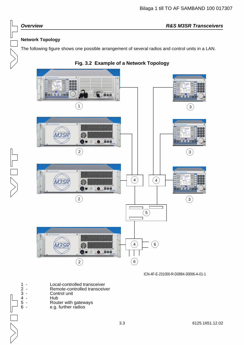
Overview R&S M3SR Transceivers
Bilaga 1 till TO AF SAMBAND 100 017307
Network Topology
The following figure shows one possible arrangement of several radios and control units in a LAN.
Fig. 3.2 Example of a Network Topology
1 - Local-controlled transceiver2 - Remote-controlled transceiver3 - Control unit4 - Hub5 - Router with gateways6 - e.g. further radios
ICN-4F-E-231000-R-D0894-30006-A-01-1
1
2
2
2
3
3
3
4 4
4
5
6
6
3.3 6125.1651.12.02

R&S M3SR Transceivers Basic Operating Concepts
Bilaga 1 till TO AF SAMBAND 100 017307
3.2 Basic Operating Concepts
This part of the documentation gives an overview of how to operate the radio via the front panel and/or a control unit. For operation via control unit, details are provided relating to the menu page structure and the possibilities to navigate within the menu tree or to change settings.
3.2.1 Radio Settings/Displays via Front Panel
The front panel contains several keys, volume controls and a RESET button, which are used to make a limited number of radio settings. LEDs are available to indicate the status of the radio.
Fig. 3.3 Radio Front Panel
1 - Indicators for selected AF signal source2 - Indicator for local mode3 - Indicators for used power supply (battery, AC/DC)4 - ON/OFF button5 - Button for local mode/special function mode6 - SELECT button for setting the AF signal for the loudspeaker/special function selector7 - Volume control for the headset8 - Connector for the headset9 - Volume control for the loudspeaker10 - Radio status indicators and RESET button11 - LAN Service connector12 - Connector for Fill Gun
ICN-4F-A-231000-R-D0894-00173-A-01-19911 10
1
2
3
4
5
6781112
6125.1651.12.02 3.4
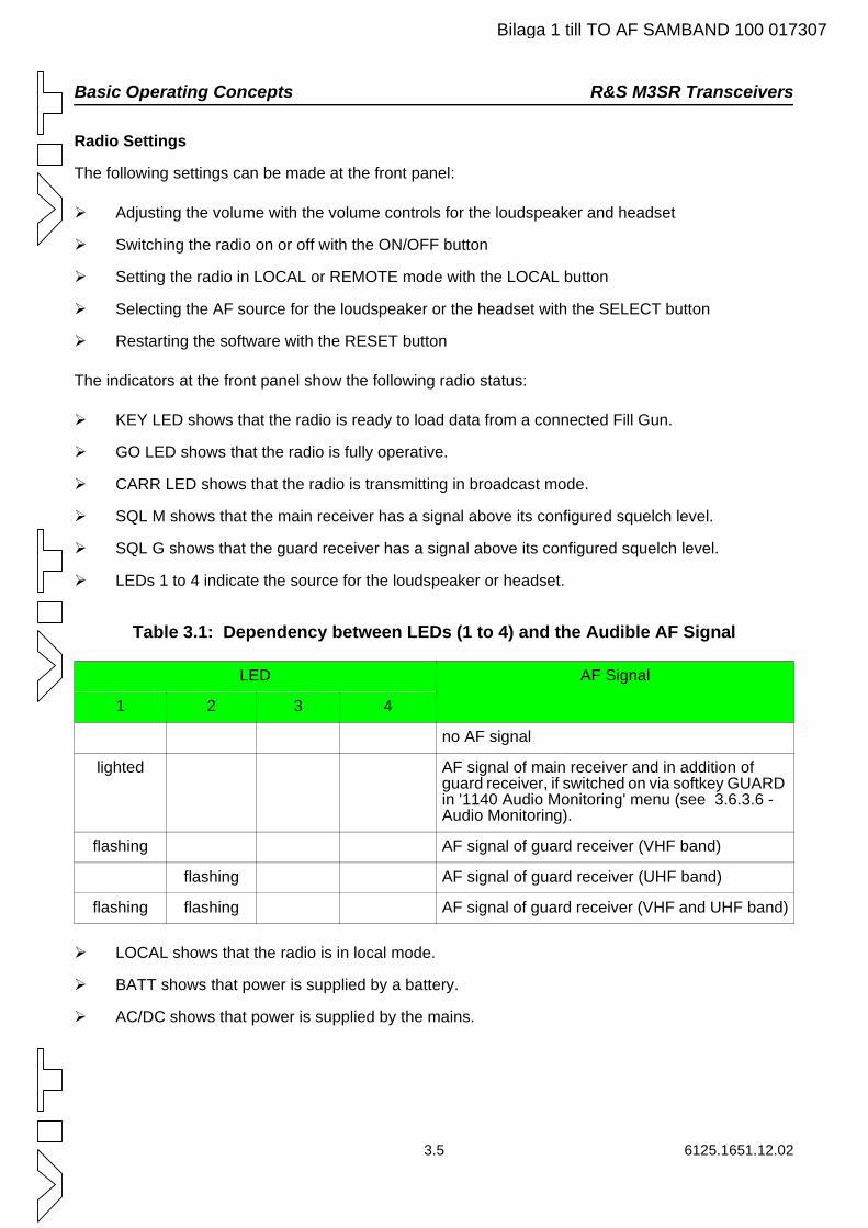
Basic Operating Concepts R&S M3SR Transceivers
Bilaga 1 till TO AF SAMBAND 100 017307
Radio Settings
The following settings can be made at the front panel:
Adjusting the volume with the volume controls for the loudspeaker and headset
Switching the radio on or off with the ON/OFF button
Setting the radio in LOCAL or REMOTE mode with the LOCAL button
Selecting the AF source for the loudspeaker or the headset with the SELECT button
Restarting the software with the RESET button
The indicators at the front panel show the following radio status:
KEY LED shows that the radio is ready to load data from a connected Fill Gun.
GO LED shows that the radio is fully operative.
CARR LED shows that the radio is transmitting in broadcast mode.
SQL M shows that the main receiver has a signal above its configured squelch level.
SQL G shows that the guard receiver has a signal above its configured squelch level.
LEDs 1 to 4 indicate the source for the loudspeaker or headset.
Table 3.1: Dependency between LEDs (1 to 4) and the Audible AF Signal
LOCAL shows that the radio is in local mode.
BATT shows that power is supplied by a battery.
AC/DC shows that power is supplied by the mains.
LED AF Signal
1 2 3 4
no AF signal
lighted AF signal of main receiver and in addition of guard receiver, if switched on via softkey GUARD in '1140 Audio Monitoring' menu (see 3.6.3.6 - Audio Monitoring).
flashing AF signal of guard receiver (VHF band)
flashing AF signal of guard receiver (UHF band)
flashing flashing AF signal of guard receiver (VHF and UHF band)
3.5 6125.1651.12.02
R&S M3SR Transceivers Basic Operating Concepts
Bilaga 1 till TO AF SAMBAND 100 017307
Setting the Signals on the Loudspeaker
By pressing the SELECT button repeatedly the settings can be changed according to Table 3.1.
Special Key Combinations
The radio has special key combinations to set the default address management and the default config-uration.
Combinations of the LOCAL and SELECT button allow the following actions:
Reset the parameters of the address mangement toIP address = 192.168.52.46subnet mask = 255.255.240.0
Reset the radio to the default configuration
For setting the default address management proceed as follows:
1 Press the LOCAL button until the LOCAL LED starts flashing (approximately 5 sec.).
2 Press the SELECT button once so that LED 1 flashes, too.
3 Press the LOCAL button again until the LOCAL LED flashes faster (approximately 5 sec.). If the default address management has been set, the LOCAL LED stops flashing and the radio restarts.
For setting the radio to the default configuration proceed as follows:
1 Press the LOCAL button until the LOCAL LED starts flashing (approximately 5 sec.).
2 Press the SELECT button twice so that LED 2 flashes, too.
3 Press the LOCAL button again until the LOCAL LED flashes faster (approximately 5 sec.) If the default configuration has been set, the LOCAL LED stops flashing and the radio restarts.
NOTE:The special key combinations of LOCAL and SELECT (3 x or 4 x) are reserved for future
use.
Change of Parameters
Changed parameters may be lost if the radio is switched off immediately after entering the new setting.
Therefore allow at least 5 seconds for the radio to store the changed parameters correctly before switching it off.
6125.1651.12.02 3.6
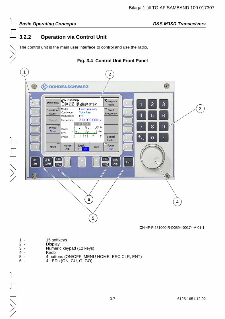
Basic Operating Concepts R&S M3SR Transceivers
Bilaga 1 till TO AF SAMBAND 100 017307
3.2.2 Operation via Control Unit
The control unit is the main user interface to control and use the radio.
Fig. 3.4 Control Unit Front Panel
1 - 15 softkeys 2 - Display3 - Numeric keypad (12 keys)4 - Knob5 - 4 buttons (ON/OFF, MENU HOME, ESC CLR, ENT)6 - 4 LEDs (ON, CU, G, GO)
ICN-4F-F-231000-R-D0894-00174-A-01-1
2
3
466
55
1
3.7 6125.1651.12.02
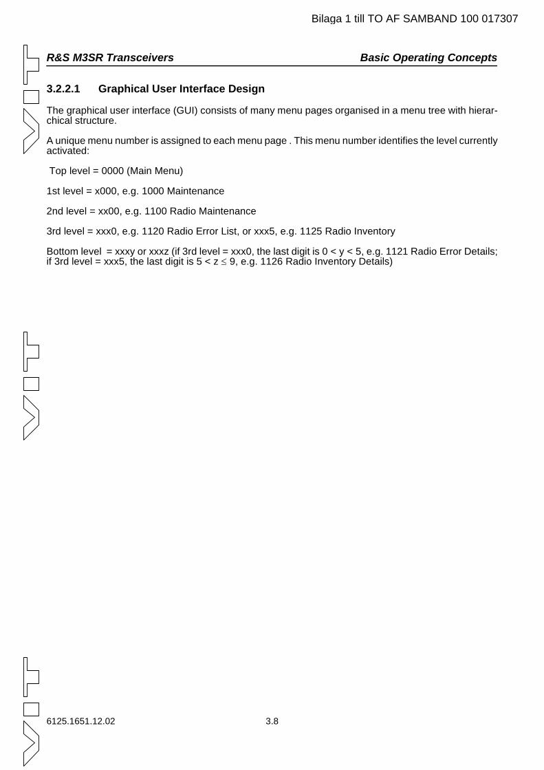
R&S M3SR Transceivers Basic Operating Concepts
Bilaga 1 till TO AF SAMBAND 100 017307
3.2.2.1 Graphical User Interface Design
The graphical user interface (GUI) consists of many menu pages organised in a menu tree with hierar-chical structure.
A unique menu number is assigned to each menu page . This menu number identifies the level currently activated:
Top level = 0000 (Main Menu)
1st level = x000, e.g. 1000 Maintenance
2nd level = xx00, e.g. 1100 Radio Maintenance
3rd level = xxx0, e.g. 1120 Radio Error List, or xxx5, e.g. 1125 Radio Inventory
Bottom level = xxxy or xxxz (if 3rd level = xxx0, the last digit is 0 < y < 5, e.g. 1121 Radio Error Details; if 3rd level = xxx5, the last digit is 5 < z ≤ 9, e.g. 1126 Radio Inventory Details)
6125.1651.12.02 3.8
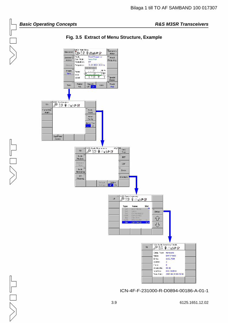
Basic Operating Concepts R&S M3SR Transceivers
Bilaga 1 till TO AF SAMBAND 100 017307
Fig. 3.5 Extract of Menu Structure, Example
ICN-4F-F-231000-R-D0894-00186-A-01-1
3.9 6125.1651.12.02
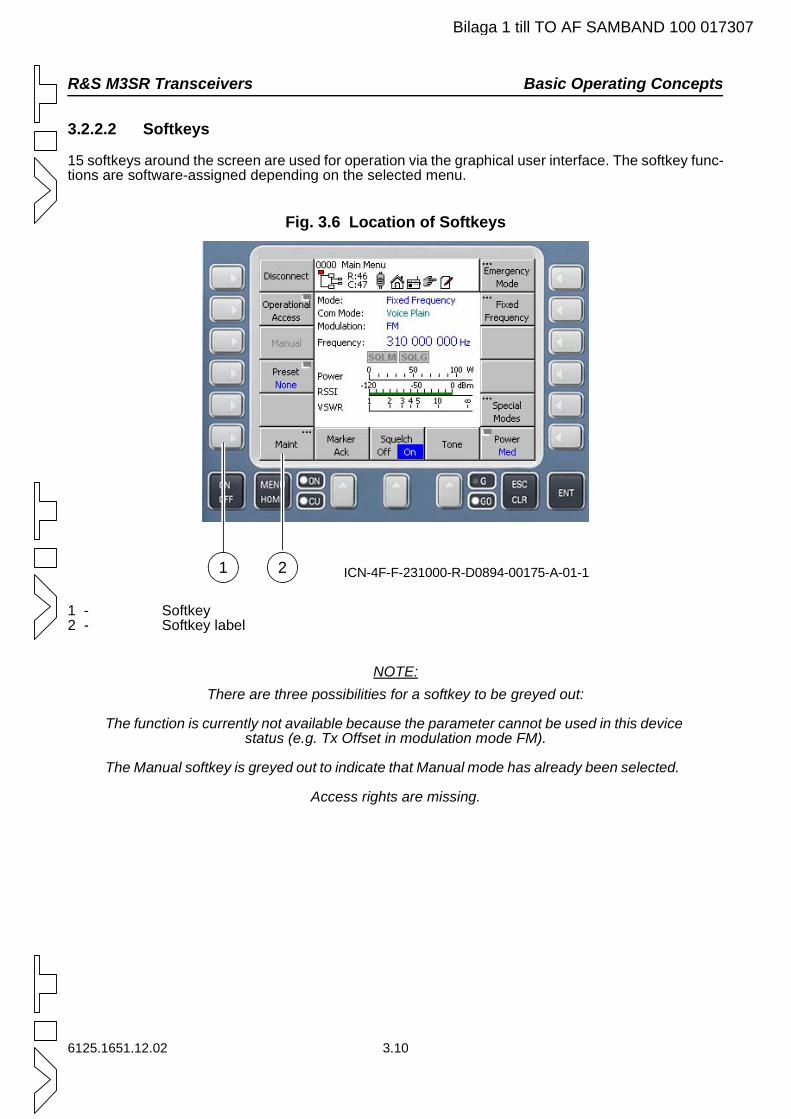
R&S M3SR Transceivers Basic Operating Concepts
Bilaga 1 till TO AF SAMBAND 100 017307
3.2.2.2 Softkeys
15 softkeys around the screen are used for operation via the graphical user interface. The softkey func-tions are software-assigned depending on the selected menu.
Fig. 3.6 Location of Softkeys
1 - Softkey2 - Softkey label
NOTE:There are three possibilities for a softkey to be greyed out:
The function is currently not available because the parameter cannot be used in this device status (e.g. Tx Offset in modulation mode FM).
The Manual softkey is greyed out to indicate that Manual mode has already been selected.
Access rights are missing.
ICN-4F-F-231000-R-D0894-00175-A-01-11 2
6125.1651.12.02 3.10
Basic Operating Concepts R&S M3SR Transceivers
Bilaga 1 till TO AF SAMBAND 100 017307
3.2.2.3 Control Unit LEDs
The control unit has the following LEDs to indicate the status:
LED ON The LED is on if the control unit is on.
The LED flashes if the control unit is off.
LED CU
The LED is on if the control unit is fully operative.
LED GO
The LED is on if the connected radio is fully operative.
LED G
The LED is on if a guard signal above the configured level is received.
3.2.2.4 Menu Page Design
Each menu page consists of a header and a central area.
Fig. 3.7 Menu Page Design with Indicators
1 - Header2 - Status indicators3 - Central area
ICN-4F-F-231000-R-D0894-00176-A-01-1
2
1
2
3
3.11 6125.1651.12.02
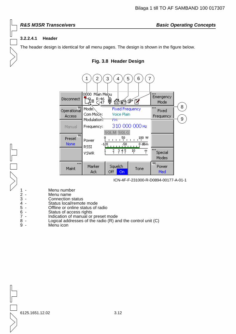
R&S M3SR Transceivers Basic Operating Concepts
Bilaga 1 till TO AF SAMBAND 100 017307
3.2.2.4.1 Header
The header design is identical for all menu pages. The design is shown in the figure below.
Fig. 3.8 Header Design
1 - Menu number2 - Menu name3 - Connection status4 - Status local/remote mode5 - Offline or online status of radio6 - Status of access rights7 - Indication of manual or preset mode8 - Logical addresses of the radio (R) and the control unit (C)9 - Menu icon
ICN-4F-F-231000-R-D0894-00177-A-01-1
1 2 3 4 5 6 7
8
9
6125.1651.12.02 3.12
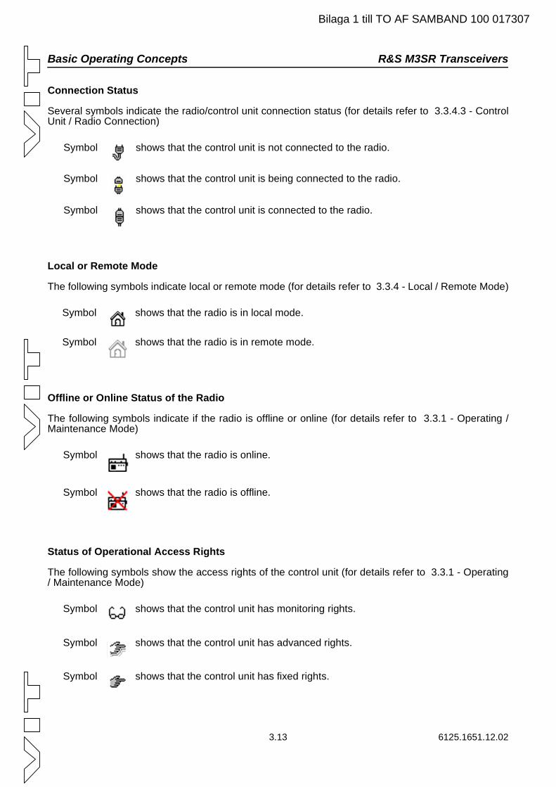
Basic Operating Concepts R&S M3SR Transceivers
Bilaga 1 till TO AF SAMBAND 100 017307
Connection Status
Several symbols indicate the radio/control unit connection status (for details refer to 3.3.4.3 - Control Unit / Radio Connection)
Local or Remote Mode
The following symbols indicate local or remote mode (for details refer to 3.3.4 - Local / Remote Mode)
Offline or Online Status of the Radio
The following symbols indicate if the radio is offline or online (for details refer to 3.3.1 - Operating / Maintenance Mode)
Status of Operational Access Rights
The following symbols show the access rights of the control unit (for details refer to 3.3.1 - Operating / Maintenance Mode)
Symbol shows that the control unit is not connected to the radio.
Symbol shows that the control unit is being connected to the radio.
Symbol shows that the control unit is connected to the radio.
Symbol shows that the radio is in local mode.
Symbol shows that the radio is in remote mode.
Symbol shows that the radio is online.
Symbol shows that the radio is offline.
Symbol shows that the control unit has monitoring rights.
Symbol shows that the control unit has advanced rights.
Symbol shows that the control unit has fixed rights.
3.13 6125.1651.12.02
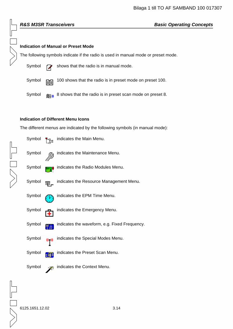
R&S M3SR Transceivers Basic Operating Concepts
Bilaga 1 till TO AF SAMBAND 100 017307
Indication of Manual or Preset Mode
The following symbols indicate if the radio is used in manual mode or preset mode.
Indication of Different Menu Icons
The different menus are indicated by the following symbols (in manual mode):
Symbol shows that the radio is in manual mode.
Symbol 100 shows that the radio is in preset mode on preset 100.
Symbol 8 shows that the radio is in preset scan mode on preset 8.
Symbol indicates the Main Menu.
Symbol indicates the Maintenance Menu.
Symbol indicates the Radio Modules Menu.
Symbol indicates the Resource Management Menu.
Symbol indicates the EPM Time Menu.
Symbol indicates the Emergency Menu.
Symbol indicates the waveform, e.g. Fixed Frequency.
Symbol indicates the Special Modes Menu.
Symbol indicates the Preset Scan Menu.
Symbol indicates the Context Menu.
6125.1651.12.02 3.14
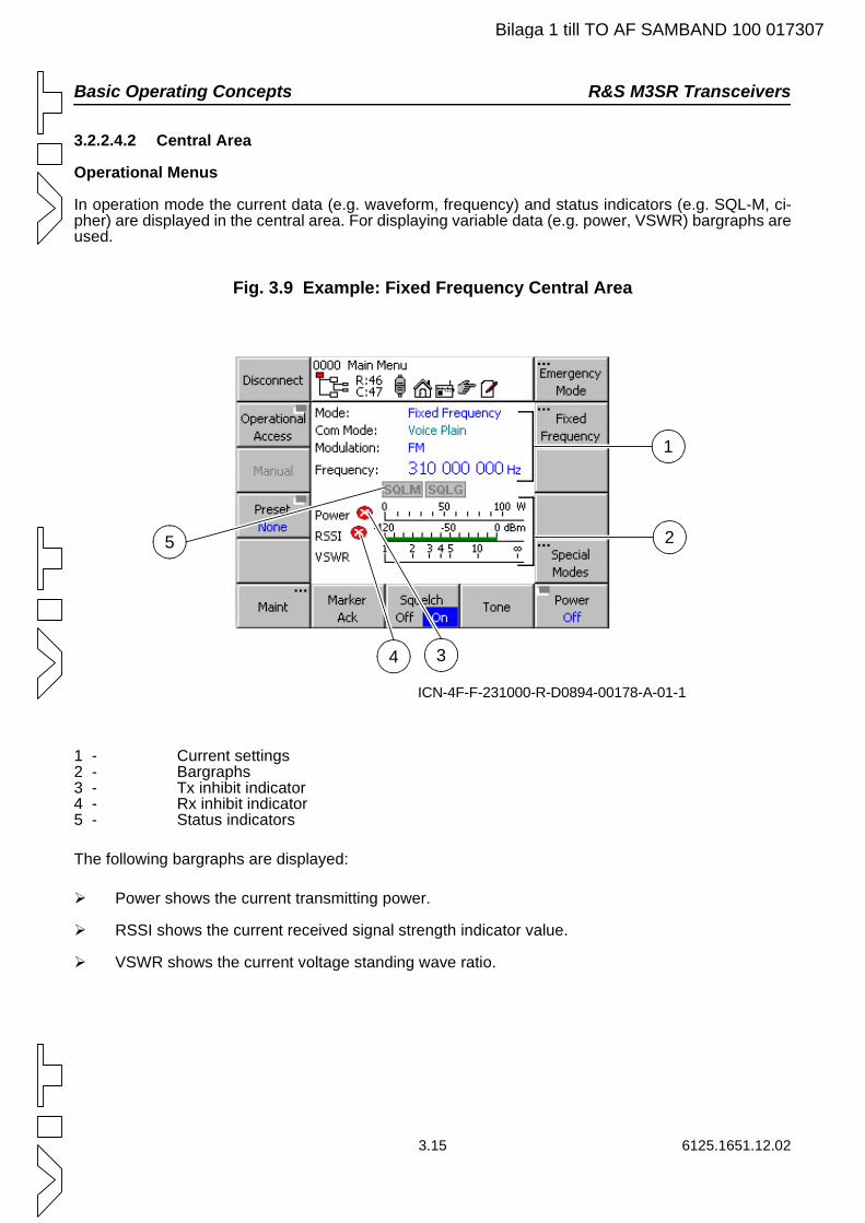
Basic Operating Concepts R&S M3SR Transceivers
Bilaga 1 till TO AF SAMBAND 100 017307
3.2.2.4.2 Central Area
Operational Menus
In operation mode the current data (e.g. waveform, frequency) and status indicators (e.g. SQL-M, ci-pher) are displayed in the central area. For displaying variable data (e.g. power, VSWR) bargraphs are used.
Fig. 3.9 Example: Fixed Frequency Central Area
1 - Current settings2 - Bargraphs3 - Tx inhibit indicator4 - Rx inhibit indicator5 - Status indicators
The following bargraphs are displayed:
Power shows the current transmitting power.
RSSI shows the current received signal strength indicator value.
VSWR shows the current voltage standing wave ratio.
ICN-4F-F-231000-R-D0894-00178-A-01-1
34
1
5 2
3.15 6125.1651.12.02
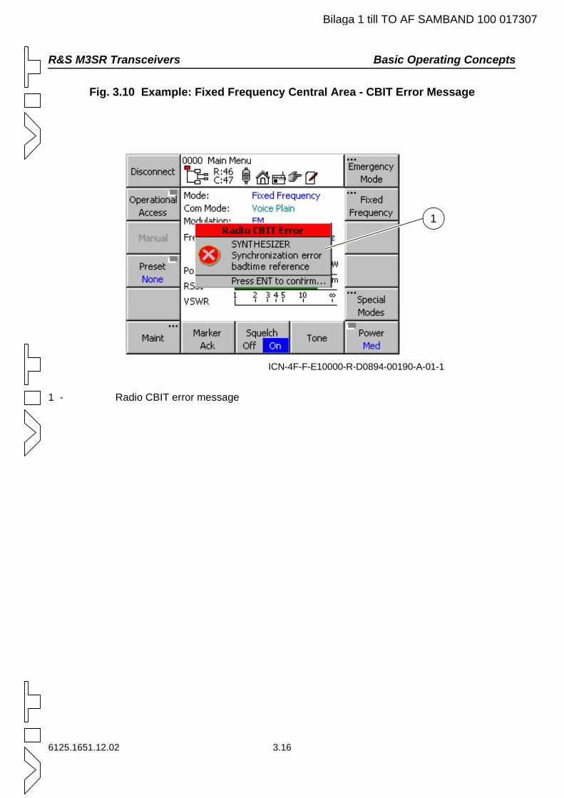
R&S M3SR Transceivers Basic Operating Concepts
Bilaga 1 till TO AF SAMBAND 100 017307
Fig. 3.10 Example: Fixed Frequency Central Area - CBIT Error Message
1 - Radio CBIT error message
ICN-4F-F-E10000-R-D0894-00190-A-01-1
1
6125.1651.12.02 3.16
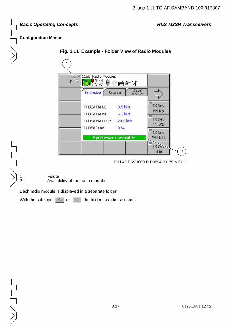
Basic Operating Concepts R&S M3SR Transceivers
Bilaga 1 till TO AF SAMBAND 100 017307
Configuration Menus
Fig. 3.11 Example - Folder View of Radio Modules
1 - Folder2 - Availability of the radio module
Each radio module is displayed in a separate folder.
With the softkeys or the folders can be selected.
ICN-4F-E-231000-R-D0894-00179-A-01-1
2
1
3.17 6125.1651.12.02
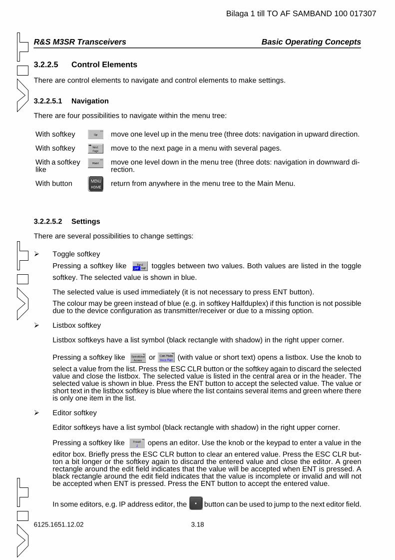
R&S M3SR Transceivers Basic Operating Concepts
Bilaga 1 till TO AF SAMBAND 100 017307
3.2.2.5 Control Elements
There are control elements to navigate and control elements to make settings.
3.2.2.5.1 Navigation
There are four possibilities to navigate within the menu tree:
3.2.2.5.2 Settings
There are several possibilities to change settings:
Toggle softkey Pressing a softkey like toggles between two values. Both values are listed in the toggle softkey. The selected value is shown in blue.
The selected value is used immediately (it is not necessary to press ENT button).The colour may be green instead of blue (e.g. in softkey Halfduplex) if this function is not possible due to the device configuration as transmitter/receiver or due to a missing option.
Listbox softkey
Listbox softkeys have a list symbol (black rectangle with shadow) in the right upper corner.
Pressing a softkey like or (with value or short text) opens a listbox. Use the knob to select a value from the list. Press the ESC CLR button or the softkey again to discard the selected value and close the listbox. The selected value is listed in the central area or in the header. The selected value is shown in blue. Press the ENT button to accept the selected value. The value or short text in the listbox softkey is blue where the list contains several items and green where there is only one item in the list.
Editor softkey
Editor softkeys have a list symbol (black rectangle with shadow) in the right upper corner.
Pressing a softkey like opens an editor. Use the knob or the keypad to enter a value in the editor box. Briefly press the ESC CLR button to clear an entered value. Press the ESC CLR but-ton a bit longer or the softkey again to discard the entered value and close the editor. A green rectangle around the edit field indicates that the value will be accepted when ENT is pressed. A black rectangle around the edit field indicates that the value is incomplete or invalid and will not be accepted when ENT is pressed. Press the ENT button to accept the entered value.
In some editors, e.g. IP address editor, the button can be used to jump to the next editor field.
With softkey move one level up in the menu tree (three dots: navigation in upward direction.
With softkey move to the next page in a menu with several pages.
With a softkey like
move one level down in the menu tree (three dots: navigation in downward di-rection.
With button return from anywhere in the menu tree to the Main Menu.
6125.1651.12.02 3.18
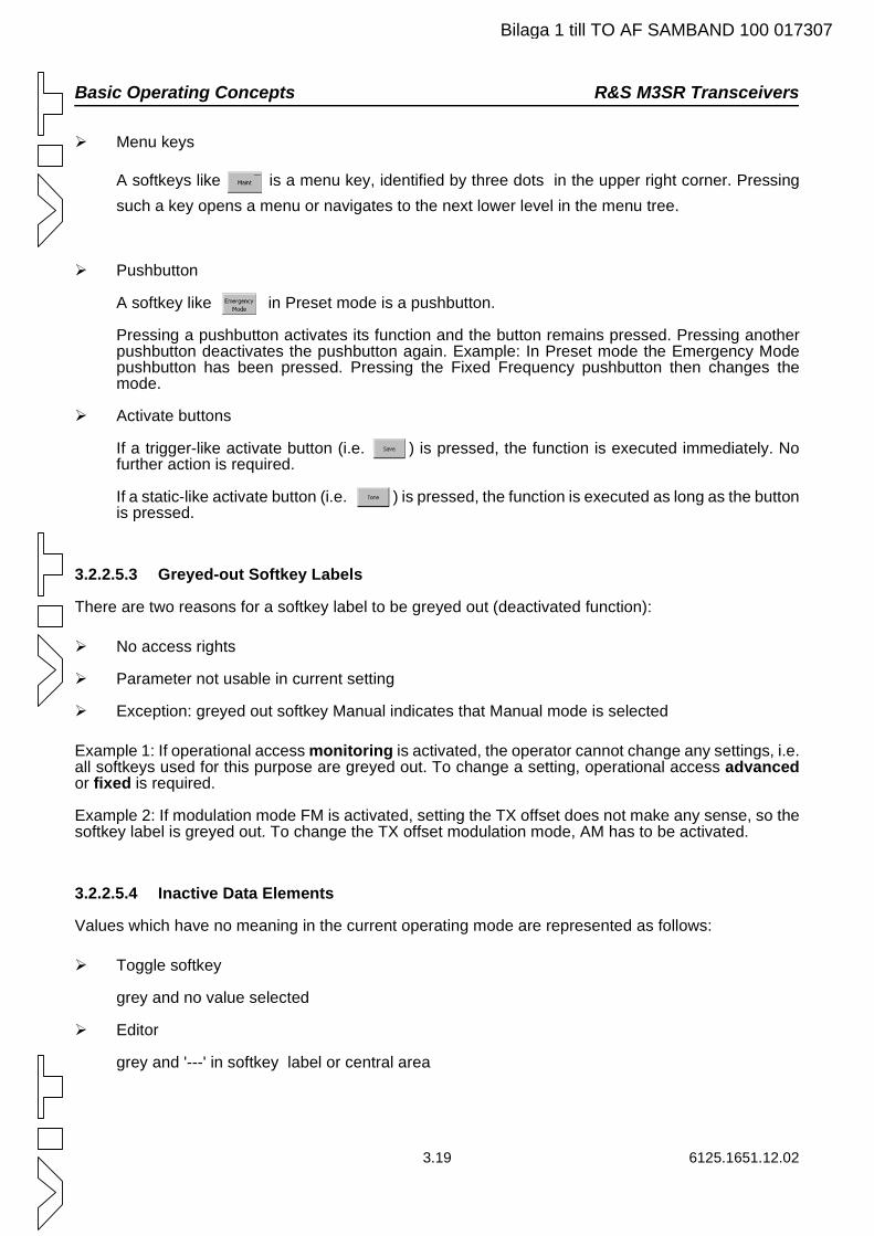
Basic Operating Concepts R&S M3SR Transceivers
Bilaga 1 till TO AF SAMBAND 100 017307
Menu keys
A softkeys like is a menu key, identified by three dots in the upper right corner. Pressing such a key opens a menu or navigates to the next lower level in the menu tree.
Pushbutton
A softkey like in Preset mode is a pushbutton.
Pressing a pushbutton activates its function and the button remains pressed. Pressing another pushbutton deactivates the pushbutton again. Example: In Preset mode the Emergency Mode pushbutton has been pressed. Pressing the Fixed Frequency pushbutton then changes the mode.
Activate buttons
If a trigger-like activate button (i.e. ) is pressed, the function is executed immediately. No further action is required.
If a static-like activate button (i.e. ) is pressed, the function is executed as long as the button is pressed.
3.2.2.5.3 Greyed-out Softkey Labels
There are two reasons for a softkey label to be greyed out (deactivated function):
No access rights
Parameter not usable in current setting
Exception: greyed out softkey Manual indicates that Manual mode is selected
Example 1: If operational access monitoring is activated, the operator cannot change any settings, i.e. all softkeys used for this purpose are greyed out. To change a setting, operational access advancedor fixed is required.
Example 2: If modulation mode FM is activated, setting the TX offset does not make any sense, so the softkey label is greyed out. To change the TX offset modulation mode, AM has to be activated.
3.2.2.5.4 Inactive Data Elements
Values which have no meaning in the current operating mode are represented as follows:
Toggle softkey
grey and no value selected
Editor
grey and '---' in softkey label or central area
3.19 6125.1651.12.02
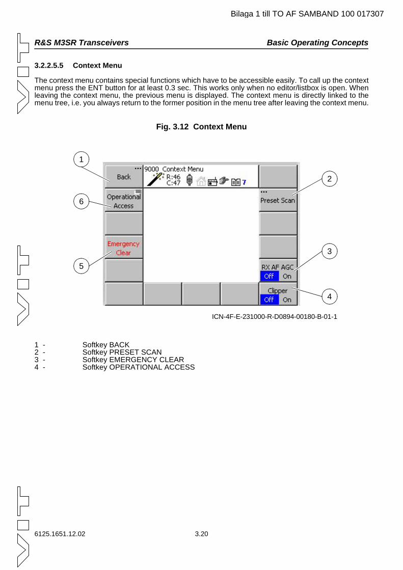
R&S M3SR Transceivers Basic Operating Concepts
Bilaga 1 till TO AF SAMBAND 100 017307
3.2.2.5.5 Context Menu
The context menu contains special functions which have to be accessible easily. To call up the context menu press the ENT button for at least 0.3 sec. This works only when no editor/listbox is open. When leaving the context menu, the previous menu is displayed. The context menu is directly linked to the menu tree, i.e. you always return to the former position in the menu tree after leaving the context menu.
Fig. 3.12 Context Menu
1 - Softkey BACK2 - Softkey PRESET SCAN3 - Softkey EMERGENCY CLEAR4 - Softkey OPERATIONAL ACCESS
ICN-4F-E-231000-R-D0894-00180-B-01-1
2
3
4
5
6
1
6125.1651.12.02 3.20
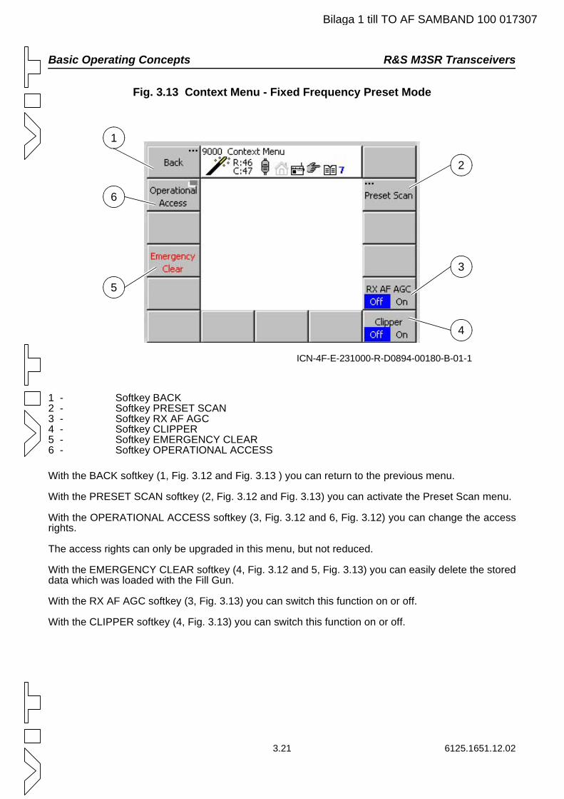
Basic Operating Concepts R&S M3SR Transceivers
Bilaga 1 till TO AF SAMBAND 100 017307
Fig. 3.13 Context Menu - Fixed Frequency Preset Mode
1 - Softkey BACK2 - Softkey PRESET SCAN3 - Softkey RX AF AGC4 - Softkey CLIPPER5 - Softkey EMERGENCY CLEAR6 - Softkey OPERATIONAL ACCESS
With the BACK softkey (1, Fig. 3.12 and Fig. 3.13 ) you can return to the previous menu.
With the PRESET SCAN softkey (2, Fig. 3.12 and Fig. 3.13) you can activate the Preset Scan menu.
With the OPERATIONAL ACCESS softkey (3, Fig. 3.12 and 6, Fig. 3.12) you can change the access rights.
The access rights can only be upgraded in this menu, but not reduced.
With the EMERGENCY CLEAR softkey (4, Fig. 3.12 and 5, Fig. 3.13) you can easily delete the stored data which was loaded with the Fill Gun.
With the RX AF AGC softkey (3, Fig. 3.13) you can switch this function on or off.
With the CLIPPER softkey (4, Fig. 3.13) you can switch this function on or off.
ICN-4F-E-231000-R-D0894-00180-B-01-1
2
3
4
5
6
1
3.21 6125.1651.12.02
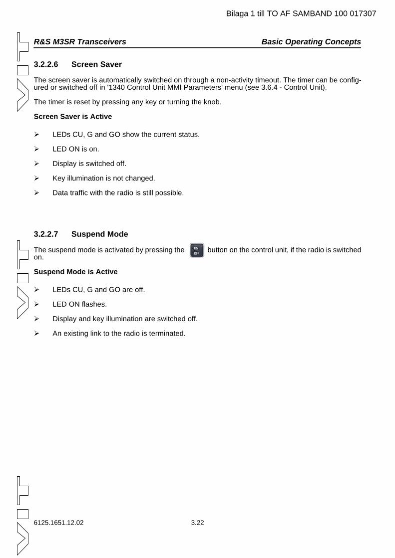
R&S M3SR Transceivers Basic Operating Concepts
Bilaga 1 till TO AF SAMBAND 100 017307
3.2.2.6 Screen Saver
The screen saver is automatically switched on through a non-activity timeout. The timer can be config-ured or switched off in '1340 Control Unit MMI Parameters' menu (see 3.6.4 - Control Unit).
The timer is reset by pressing any key or turning the knob.
Screen Saver is Active
LEDs CU, G and GO show the current status.
LED ON is on.
Display is switched off.
Key illumination is not changed.
Data traffic with the radio is still possible.
3.2.2.7 Suspend Mode
The suspend mode is activated by pressing the button on the control unit, if the radio is switched on.
Suspend Mode is Active
LEDs CU, G and GO are off.
LED ON flashes.
Display and key illumination are switched off.
An existing link to the radio is terminated.
6125.1651.12.02 3.22
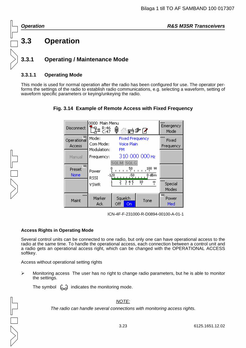
Operation R&S M3SR Transceivers
Bilaga 1 till TO AF SAMBAND 100 017307
3.3 Operation
3.3.1 Operating / Maintenance Mode
3.3.1.1 Operating Mode
This mode is used for normal operation after the radio has been configured for use. The operator per-forms the settings of the radio to establish radio communications, e.g. selecting a waveform, setting of waveform specific parameters or keying/unkeying the radio.
Fig. 3.14 Example of Remote Access with Fixed Frequency
Access Rights in Operating Mode
Several control units can be connected to one radio, but only one can have operational access to the radio at the same time. To handle the operational access, each connection between a control unit and a radio gets an operational access right, which can be changed with the OPERATIONAL ACCESS softkey.
Access without operational setting rights
Monitoring access The user has no right to change radio parameters, but he is able to monitor the settings.
The symbol indicates the monitoring mode.
NOTE:The radio can handle several connections with monitoring access rights.
ICN-4F-F-231000-R-D0894-00100-A-01-1
3.23 6125.1651.12.02
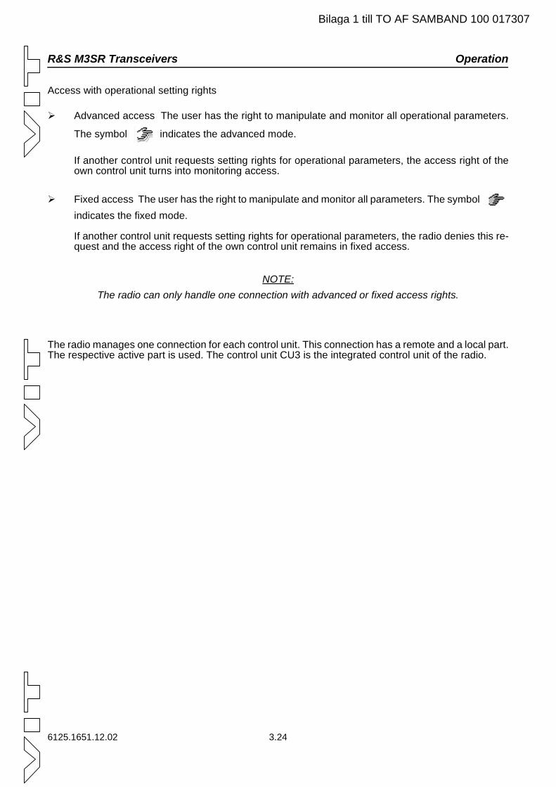
R&S M3SR Transceivers Operation
Bilaga 1 till TO AF SAMBAND 100 017307
Access with operational setting rights
Advanced access The user has the right to manipulate and monitor all operational parameters.
The symbol indicates the advanced mode.
If another control unit requests setting rights for operational parameters, the access right of the own control unit turns into monitoring access.
Fixed access The user has the right to manipulate and monitor all parameters. The symbol indicates the fixed mode.
If another control unit requests setting rights for operational parameters, the radio denies this re-quest and the access right of the own control unit remains in fixed access.
NOTE:The radio can only handle one connection with advanced or fixed access rights.
The radio manages one connection for each control unit. This connection has a remote and a local part. The respective active part is used. The control unit CU3 is the integrated control unit of the radio.
6125.1651.12.02 3.24
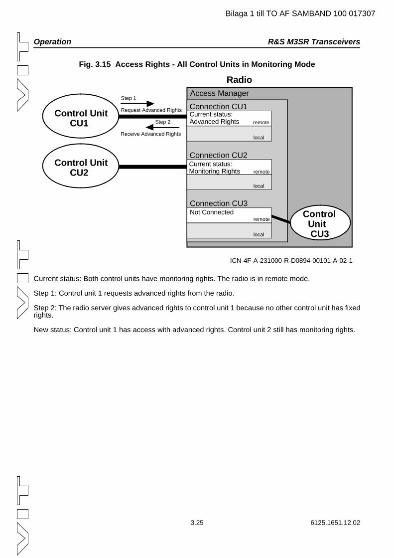
Operation R&S M3SR Transceivers
Bilaga 1 till TO AF SAMBAND 100 017307
Fig. 3.15 Access Rights - All Control Units in Monitoring Mode
Current status: Both control units have monitoring rights. The radio is in remote mode.
Step 1: Control unit 1 requests advanced rights from the radio.
Step 2: The radio server gives advanced rights to control unit 1 because no other control unit has fixed rights.
New status: Control unit 1 has access with advanced rights. Control unit 2 still has monitoring rights.
ICN-4F-A-231000-R-D0894-00101-A-02-1
Step 1
Request Advanced Rights
Step 2Control Unit CU1
Control Unit CU2
Receive Advanced Rights
Access Manager
Connection CU1
Radio
local
local
local
Current status:Advanced Rights remote
remote
remote
Connection CU2
Connection CU3
Current status:Monitoring Rights
Not Connected Control Unit CU3
3.25 6125.1651.12.02

R&S M3SR Transceivers Operation
Bilaga 1 till TO AF SAMBAND 100 017307
Fig. 3.16 Access Rights - Concurrent Access Rights
Current status: Control unit 1 has advanced rights, control unit 2 has monitoring rights. The radio is in remote mode.
Step 1: Control unit 2 requests advanced rights from the radio.
Step 2: The radio server gives advanced rights to the control unit 2 because no other control unit has fixed rights.
Step 3: The access rights of control unit 1 are set back from advanced rights to monitoring rights.
New status: Control unit 1 has access with monitoring rights. Control unit 2 has access with advanced rights.
ICN-4F-A-231000-R-D0894-00102-A-02-1
Step 3Control Unit CU1
Control Unit CU2
Receive Monitoring Rights
Step 1
Request Advanced Rights
Step 2
Receive Advanced Rights
Access Manager
Connection CU1
Radio
local
local
local
Current status:Monitoring Rights remote
remote
remote
Connection CU2
Connection CU3
Current status:Advanced Rights
Not Connected Control Unit CU3
6125.1651.12.02 3.26
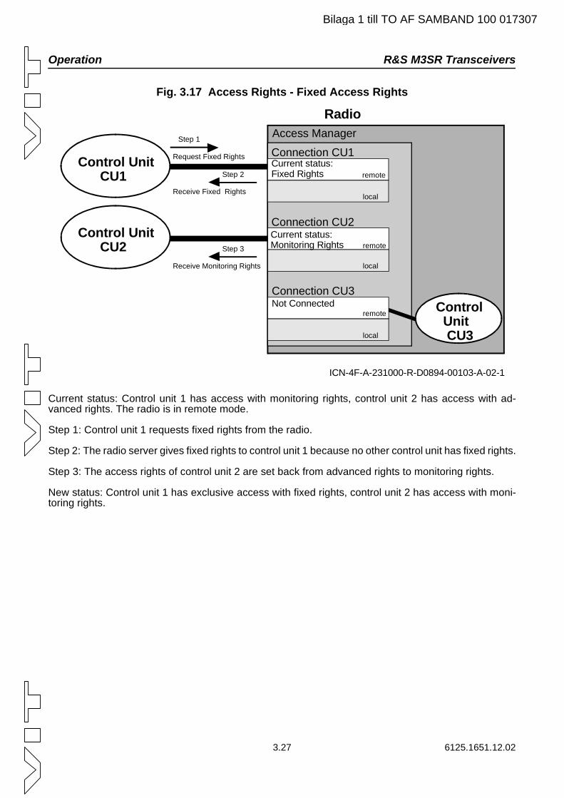
Operation R&S M3SR Transceivers
Bilaga 1 till TO AF SAMBAND 100 017307
Fig. 3.17 Access Rights - Fixed Access Rights
Current status: Control unit 1 has access with monitoring rights, control unit 2 has access with ad-vanced rights. The radio is in remote mode.
Step 1: Control unit 1 requests fixed rights from the radio.
Step 2: The radio server gives fixed rights to control unit 1 because no other control unit has fixed rights.
Step 3: The access rights of control unit 2 are set back from advanced rights to monitoring rights.
New status: Control unit 1 has exclusive access with fixed rights, control unit 2 has access with moni-toring rights.
ICN-4F-A-231000-R-D0894-00103-A-02-1
Step 2Control Unit CU1
Control Unit CU2
Control Unit CU3
Receive Fixed Rights
Step 3
Receive Monitoring Rights
Request Fixed Rights
Step 1 Access Manager
Connection CU1
Radio
local
local
local
Current status:Fixed Rights remote
remote
remote
Connection CU2
Connection CU3
Current status:Monitoring Rights
Not Connected
3.27 6125.1651.12.02
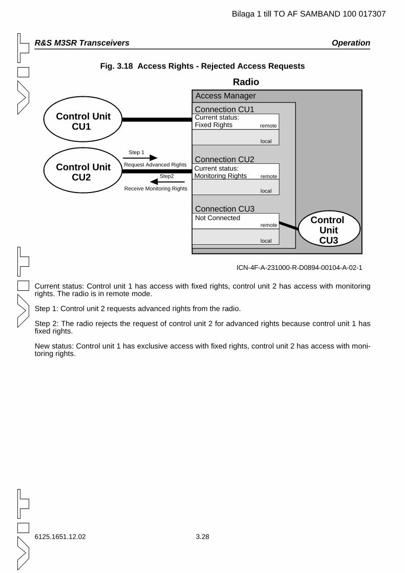
R&S M3SR Transceivers Operation
Bilaga 1 till TO AF SAMBAND 100 017307
Fig. 3.18 Access Rights - Rejected Access Requests
Current status: Control unit 1 has access with fixed rights, control unit 2 has access with monitoring rights. The radio is in remote mode.
Step 1: Control unit 2 requests advanced rights from the radio.
Step 2: The radio rejects the request of control unit 2 for advanced rights because control unit 1 has fixed rights.
New status: Control unit 1 has exclusive access with fixed rights, control unit 2 has access with moni-toring rights.
ICN-4F-A-231000-R-D0894-00104-A-02-1
Control Unit CU1
Control Unit CU2
Control UnitCU3
Step2
Receive Monitoring Rights
Step 1
Request Advanced Rights
Access Manager
Connection CU1
Radio
local
local
local
Current status:Fixed Rights remote
remote
remote
Connection CU2
Connection CU3
Current status:Monitoring Rights
Not Connected
6125.1651.12.02 3.28
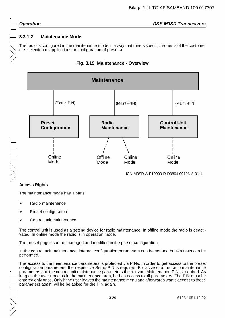
Operation R&S M3SR Transceivers
Bilaga 1 till TO AF SAMBAND 100 017307
3.3.1.2 Maintenance Mode
The radio is configured in the maintenance mode in a way that meets specific requests of the customer (i.e. selection of applications or configuration of presets).
Fig. 3.19 Maintenance - Overview
Access Rights
The maintenance mode has 3 parts
Radio maintenance
Preset configuration
Control unit maintenance
The control unit is used as a setting device for radio maintenance. In offline mode the radio is deacti-vated. In online mode the radio is in operation mode.
The preset pages can be managed and modified in the preset configuration.
In the control unit maintenance, internal configuration parameters can be set and built-in tests can be performed.
The access to the maintenance parameters is protected via PINs. In order to get access to the preset configuration parameters, the respective Setup-PIN is required. For access to the radio maintenance parameters and the control unit maintenance parameters the relevant Maintenance-PIN is required. As long as the user remains in the maintenance area, he has access to all parameters. The PIN must be entered only once. Only if the user leaves the maintenance menu and afterwards wants access to these parameters again, wil he be asked for the PIN again.
ICN-M3SR-A-E10000-R-D0894-00106-A-01-1
Maintenance
PresetConfiguration
RadioMaintenance
Control UnitMaintenance
(Setup-PIN) (Maint.-PIN) (Maint.-PIN)
Online Mode
Offline Mode
Online Mode
Online Mode
3.29 6125.1651.12.02
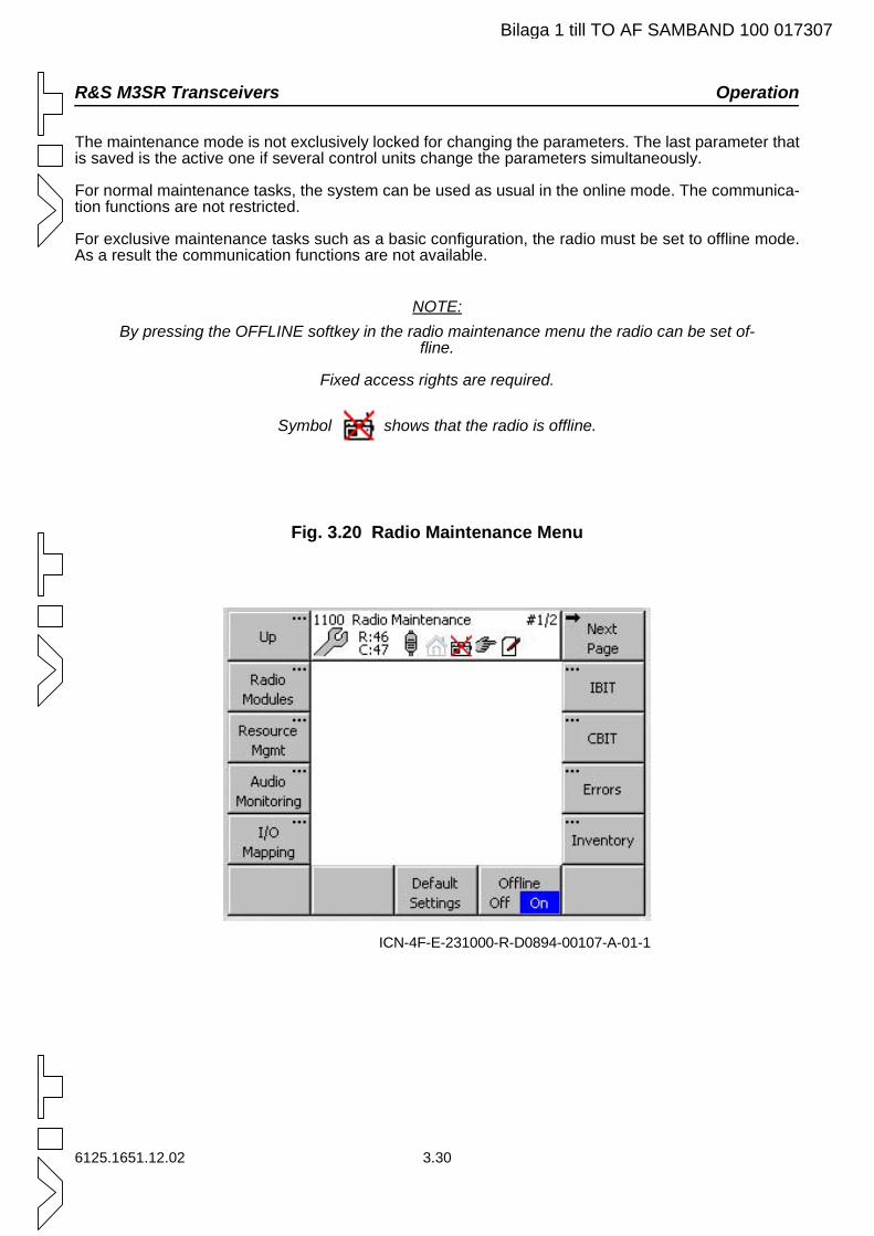
R&S M3SR Transceivers Operation
Bilaga 1 till TO AF SAMBAND 100 017307
The maintenance mode is not exclusively locked for changing the parameters. The last parameter that is saved is the active one if several control units change the parameters simultaneously.
For normal maintenance tasks, the system can be used as usual in the online mode. The communica-tion functions are not restricted.
For exclusive maintenance tasks such as a basic configuration, the radio must be set to offline mode. As a result the communication functions are not available.
NOTE:By pressing the OFFLINE softkey in the radio maintenance menu the radio can be set of-
fline.
Fixed access rights are required.
Symbol shows that the radio is offline.
Fig. 3.20 Radio Maintenance Menu
ICN-4F-E-231000-R-D0894-00107-A-01-1
6125.1651.12.02 3.30
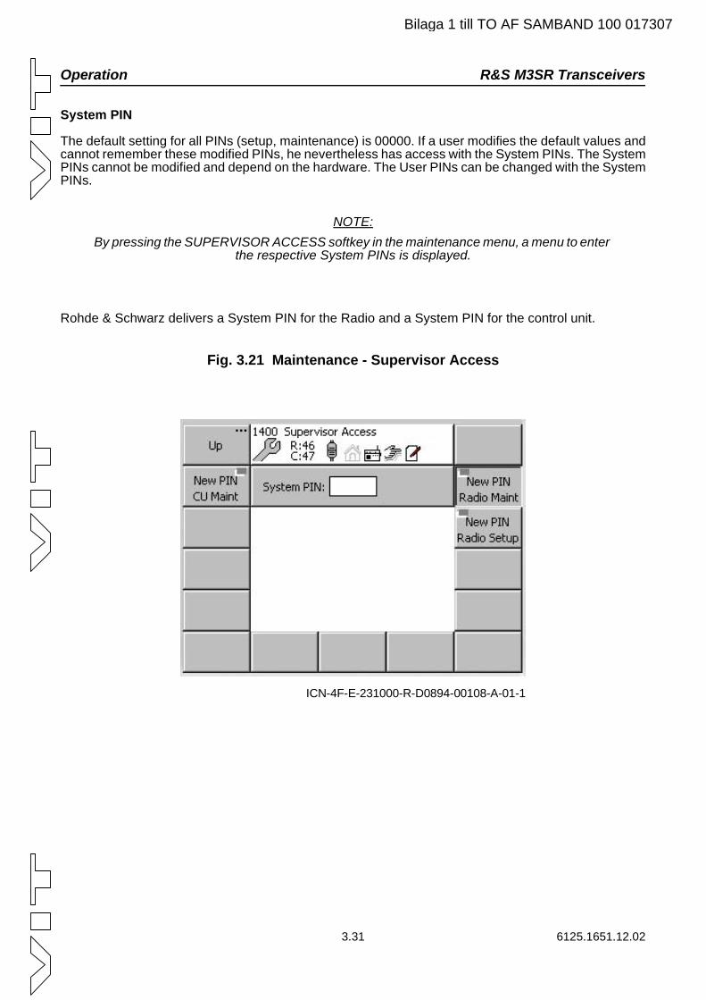
Operation R&S M3SR Transceivers
Bilaga 1 till TO AF SAMBAND 100 017307
System PIN
The default setting for all PINs (setup, maintenance) is 00000. If a user modifies the default values and cannot remember these modified PINs, he nevertheless has access with the System PINs. The System PINs cannot be modified and depend on the hardware. The User PINs can be changed with the System PINs.
NOTE:By pressing the SUPERVISOR ACCESS softkey in the maintenance menu, a menu to enter
the respective System PINs is displayed.
Rohde & Schwarz delivers a System PIN for the Radio and a System PIN for the control unit.
Fig. 3.21 Maintenance - Supervisor Access
ICN-4F-E-231000-R-D0894-00108-A-01-1
3.31 6125.1651.12.02
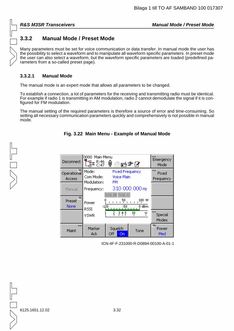
R&S M3SR Transceivers Manual Mode / Preset Mode
Bilaga 1 till TO AF SAMBAND 100 017307
3.3.2 Manual Mode / Preset Mode
Many parameters must be set for voice communication or data transfer. In manual mode the user has the possibility to select a waveform and to manipulate all waveform specific parameters. In preset mode the user can also select a waveform, but the waveform specific parameters are loaded (predefined pa-rameters from a so-called preset page).
3.3.2.1 Manual Mode
The manual mode is an expert mode that allows all parameters to be changed.
To establish a connection, a lot of parameters for the receiving and transmitting radio must be identical. For example if radio 1 is transmitting in AM modulation, radio 2 cannot demodulate the signal if it is con-figured for FM modulation.
The manual setting of the required parameters is therefore a source of error and time-consuming. So setting all necessary communication parameters quickly and comprehensively is not possible in manual mode.
Fig. 3.22 Main Menu - Example of Manual Mode
ICN-4F-F-231000-R-D0894-00100-A-01-1
6125.1651.12.02 3.32
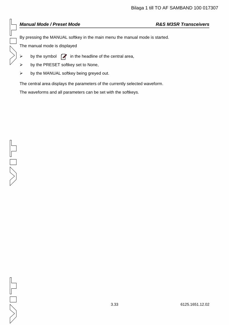
Manual Mode / Preset Mode R&S M3SR Transceivers
Bilaga 1 till TO AF SAMBAND 100 017307
By pressing the MANUAL softkey in the main menu the manual mode is started.
The manual mode is displayed
by the symbol in the headline of the central area,
by the PRESET softkey set to None,
by the MANUAL softkey being greyed out.
The central area displays the parameters of the currently selected waveform.
The waveforms and all parameters can be set with the softkeys.
3.33 6125.1651.12.02
R&S M3SR Transceivers Preset Mode
Bilaga 1 till TO AF SAMBAND 100 017307
3.3.3 Preset Mode
The preset mode is a non expert mode that allows only a few parameters to be changed. There are preset parameters that can be loaded easily. The user must only load a preset, which already has all parameters that were defined by an expert before. These preset parameters are organised in 2 do-mains (1, 2), each with 200 presets (0 to 199). The organisation of the presets is shown below. For each waveform the parameters can be set on the preset pages.
6125.1651.12.02 3.34
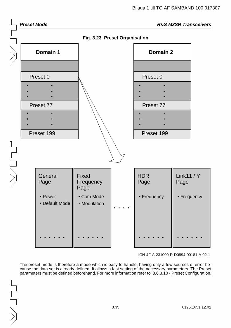
Preset Mode R&S M3SR Transceivers
Bilaga 1 till TO AF SAMBAND 100 017307
Fig. 3.23 Preset Organisation
The preset mode is therefore a mode which is easy to handle, having only a few sources of error be-cause the data set is already defined. It allows a fast setting of the necessary parameters. The Preset parameters must be defined beforehand. For more information refer to 3.6.3.10 - Preset Configuration.
ICN-4F-A-231000-R-D0894-00181-A-02-1
Domain 1
Preset 0
Preset 77
Preset 199
Domain 2
Preset 0
Preset 77
Preset 199
GeneralPage
PowerDefault Mode
FixedFrequency Page
Com ModeModulation
HDRPage
Frequency
Link11 / YPage
Frequency
3.35 6125.1651.12.02
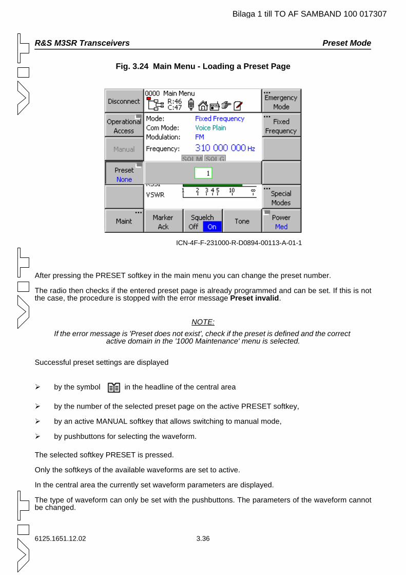
R&S M3SR Transceivers Preset Mode
Bilaga 1 till TO AF SAMBAND 100 017307
Fig. 3.24 Main Menu - Loading a Preset Page
After pressing the PRESET softkey in the main menu you can change the preset number.
The radio then checks if the entered preset page is already programmed and can be set. If this is not the case, the procedure is stopped with the error message Preset invalid.
NOTE:If the error message is 'Preset does not exist', check if the preset is defined and the correct
active domain in the '1000 Maintenance' menu is selected.
Successful preset settings are displayed
by the symbol in the headline of the central area
by the number of the selected preset page on the active PRESET softkey,
by an active MANUAL softkey that allows switching to manual mode,
by pushbuttons for selecting the waveform.
The selected softkey PRESET is pressed.
Only the softkeys of the available waveforms are set to active.
In the central area the currently set waveform parameters are displayed.
The type of waveform can only be set with the pushbuttons. The parameters of the waveform cannot be changed.
ICN-4F-F-231000-R-D0894-00113-A-01-1
6125.1651.12.02 3.36
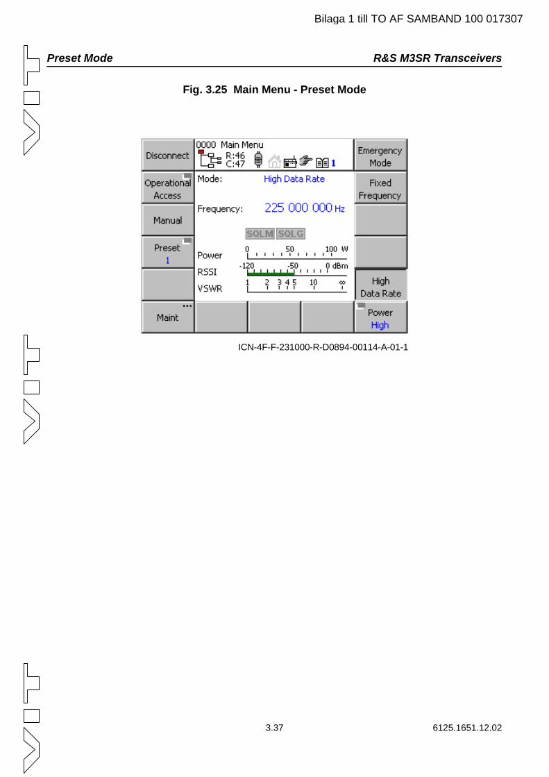
Preset Mode R&S M3SR Transceivers
Bilaga 1 till TO AF SAMBAND 100 017307
Fig. 3.25 Main Menu - Preset Mode
ICN-4F-F-231000-R-D0894-00114-A-01-1
3.37 6125.1651.12.02
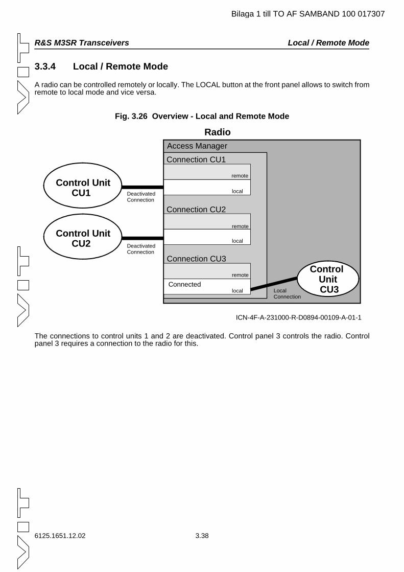
R&S M3SR Transceivers Local / Remote Mode
Bilaga 1 till TO AF SAMBAND 100 017307
3.3.4 Local / Remote Mode
A radio can be controlled remotely or locally. The LOCAL button at the front panel allows to switch from remote to local mode and vice versa.
Fig. 3.26 Overview - Local and Remote Mode
The connections to control units 1 and 2 are deactivated. Control panel 3 controls the radio. Control panel 3 requires a connection to the radio for this.
ICN-4F-A-231000-R-D0894-00109-A-01-1
Control Unit CU1
Control Unit CU2
Control Unit CU3
DeactivatedConnection
Local Connection
Access Manager
Connection CU1
Radio
local
local
local
remote
remote
remote
Connection CU2
Connection CU3
Connected
DeactivatedConnection
6125.1651.12.02 3.38
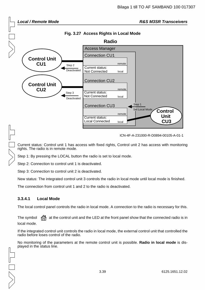
Local / Remote Mode R&S M3SR Transceivers
Bilaga 1 till TO AF SAMBAND 100 017307
Fig. 3.27 Access Rights in Local Mode
Current status: Control unit 1 has access with fixed rights, Control unit 2 has access with monitoring rights. The radio is in remote mode.
Step 1: By pressing the LOCAL button the radio is set to local mode.
Step 2: Connection to control unit 1 is deactivated.
Step 3: Connection to control unit 2 is deactivated.
New status: The integrated control unit 3 controls the radio in local mode until local mode is finished.
The connection from control unit 1 and 2 to the radio is deactivated.
3.3.4.1 Local Mode
The local control panel controls the radio in local mode. A connection to the radio is necessary for this.
The symbol at the control unit and the LED at the front panel show that the connected radio is in local mode.
If the integrated control unit controls the radio in local mode, the external control unit that controlled the radio before loses control of the radio.
No monitoring of the parameters at the remote control unit is possible. Radio in local mode is dis-played in the status line.
ICN-4F-A-231000-R-D0894-00105-A-01-1
Control Unit CU1
Control Unit CU2
Control Unit CU3
Step 3
Step 2
Deactivated
Step 1
Set Local Mode
Current status:Not Connected
Access Manager
Connection CU1
Radio
local
local
local
Current status:Not Connected
remote
remote
remote
Connection CU2
Connection CU3
Current status:Local Connected
Deactivated
3.39 6125.1651.12.02
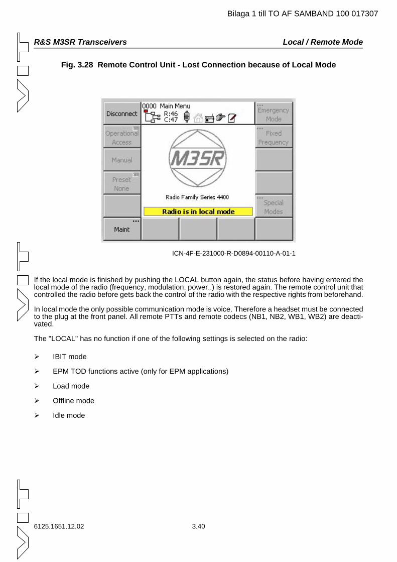
R&S M3SR Transceivers Local / Remote Mode
Bilaga 1 till TO AF SAMBAND 100 017307
Fig. 3.28 Remote Control Unit - Lost Connection because of Local Mode
If the local mode is finished by pushing the LOCAL button again, the status before having entered the local mode of the radio (frequency, modulation, power..) is restored again. The remote control unit that controlled the radio before gets back the control of the radio with the respective rights from beforehand.
In local mode the only possible communication mode is voice. Therefore a headset must be connected to the plug at the front panel. All remote PTTs and remote codecs (NB1, NB2, WB1, WB2) are deacti-vated.
The "LOCAL" has no function if one of the following settings is selected on the radio:
IBIT mode
EPM TOD functions active (only for EPM applications)
Load mode
Offline mode
Idle mode
ICN-4F-E-231000-R-D0894-00110-A-01-1
6125.1651.12.02 3.40
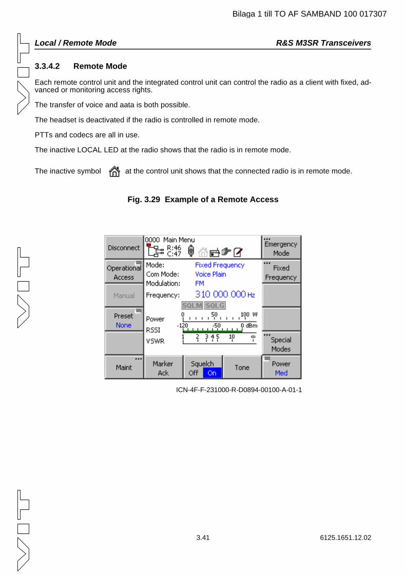
Local / Remote Mode R&S M3SR Transceivers
Bilaga 1 till TO AF SAMBAND 100 017307
3.3.4.2 Remote Mode
Each remote control unit and the integrated control unit can control the radio as a client with fixed, ad-vanced or monitoring access rights.
The transfer of voice and aata is both possible.
The headset is deactivated if the radio is controlled in remote mode.
PTTs and codecs are all in use.
The inactive LOCAL LED at the radio shows that the radio is in remote mode.
The inactive symbol at the control unit shows that the connected radio is in remote mode.
Fig. 3.29 Example of a Remote Access
ICN-4F-F-231000-R-D0894-00100-A-01-1
3.41 6125.1651.12.02
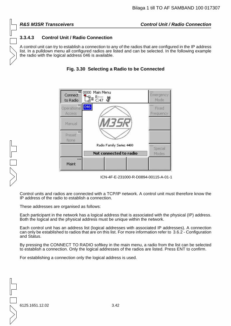
R&S M3SR Transceivers Control Unit / Radio Connection
Bilaga 1 till TO AF SAMBAND 100 017307
3.3.4.3 Control Unit / Radio Connection
A control unit can try to establish a connection to any of the radios that are configured in the IP address list. In a pulldown menu all configured radios are listed and can be selected. In the following example the radio with the logical address 046 is available.
Fig. 3.30 Selecting a Radio to be Connected
Control units and radios are connected with a TCP/IP network. A control unit must therefore know the IP address of the radio to establish a connection.
These addresses are organised as follows:
Each participant in the network has a logical address that is associated with the physical (IP) address. Both the logical and the physical address must be unique within the network.
Each control unit has an address list (logical addresses with associated IP addresses). A connection can only be established to radios that are on this list. For more information refer to 3.6.2 - Configuration and Status.
By pressing the CONNECT TO RADIO softkey in the main menu, a radio from the list can be selected to establish a connection. Only the logical addresses of the radios are listed. Press ENT to confirm.
For establishing a connection only the logical address is used.
ICN-4F-E-231000-R-D0894-00115-A-01-1
6125.1651.12.02 3.42
Control Unit / Radio Connection R&S M3SR Transceivers
3.43 6125.1651.12.02
A connection can have 3 status types:
Disconnected
There is no connection to the radio.
The symbol in the headline shows that the control unit is not connected. The message Not connected to radio is displayed in the status line. Radio specific softkeys arenot active. By pressing the CONNECT TO RADIO softkey a list of logical addresses of radioswhich are configured in the control unit is displayed. If the list is empty or the desired Radio is notlisted, the address list must first be modified. Each control unit has an address list (logical ad-dresses with associated IP addresses). A connection can only be established to radios that arelisted on this list. For more information refer to 3.6.2 - Configuration and Status.
If a logical address is selected, the control unit tries to establish a connection. This correspondsto the connecting status.In order to disconnect press the Disconnect button at least half a second. This delay has beenimplemented to prevent inadvertent disconnection.
Connecting
The control unit tries to establish a connection to the selected radio with the respective logicaladdress. This is done as long as the connection is being established or the user interrupts theprocedure.
The symbol at the control unit shows that the control unit is trying to establish a connectionto the selected Radio.
Connecting to radio is displayed in the status line. Radio specific softkeys are not active.
The connecting status can be very short if the radio is powered on, so that the user does not no-tice this status.
Connected
In this status the control unit can communicate with the radio.
The symbol at the control unit shows that the control unit has established a connection tothe selected radio.
If the connection is broken, the control unit changes to the connecting status.
Bilaga 1 till TO AF SAMBAND 100 017307
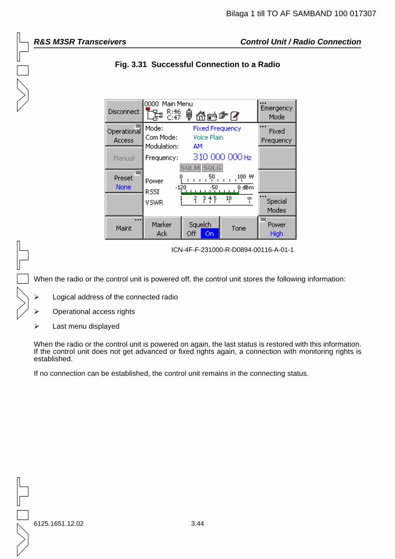
R&S M3SR Transceivers Control Unit / Radio Connection
Bilaga 1 till TO AF SAMBAND 100 017307
Fig. 3.31 Successful Connection to a Radio
When the radio or the control unit is powered off, the control unit stores the following information:
Logical address of the connected radio
Operational access rights
Last menu displayed
When the radio or the control unit is powered on again, the last status is restored with this information. If the control unit does not get advanced or fixed rights again, a connection with monitoring rights is established.
If no connection can be established, the control unit remains in the connecting status.
ICN-4F-F-231000-R-D0894-00116-A-01-1
6125.1651.12.02 3.44
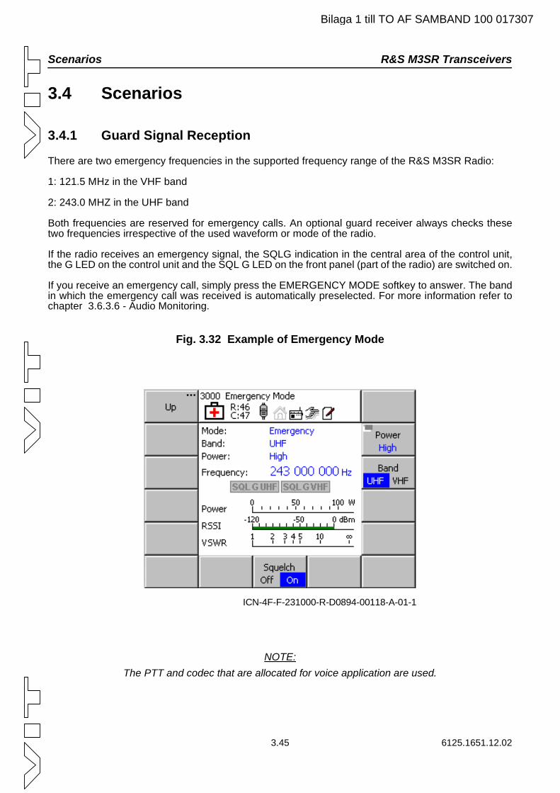
Scenarios R&S M3SR Transceivers
Bilaga 1 till TO AF SAMBAND 100 017307
3.4 Scenarios
3.4.1 Guard Signal Reception
There are two emergency frequencies in the supported frequency range of the R&S M3SR Radio:
1: 121.5 MHz in the VHF band
2: 243.0 MHZ in the UHF band
Both frequencies are reserved for emergency calls. An optional guard receiver always checks these two frequencies irrespective of the used waveform or mode of the radio.
If the radio receives an emergency signal, the SQLG indication in the central area of the control unit, the G LED on the control unit and the SQL G LED on the front panel (part of the radio) are switched on.
If you receive an emergency call, simply press the EMERGENCY MODE softkey to answer. The band in which the emergency call was received is automatically preselected. For more information refer to chapter 3.6.3.6 - Audio Monitoring.
Fig. 3.32 Example of Emergency Mode
NOTE:The PTT and codec that are allocated for voice application are used.
ICN-4F-F-231000-R-D0894-00118-A-01-1
3.45 6125.1651.12.02
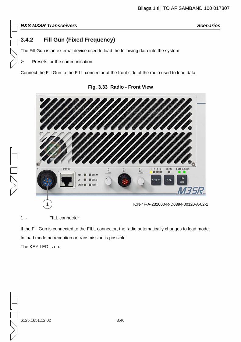
R&S M3SR Transceivers Scenarios
Bilaga 1 till TO AF SAMBAND 100 017307
3.4.2 Fill Gun (Fixed Frequency)
The Fill Gun is an external device used to load the following data into the system:
Presets for the communication
Connect the Fill Gun to the FILL connector at the front side of the radio used to load data.
Fig. 3.33 Radio - Front View
1 - FILL connector
If the Fill Gun is connected to the FILL connector, the radio automatically changes to load mode.
In load mode no reception or transmission is possible.
The KEY LED is on.
ICN-4F-A-231000-R-D0894-00120-A-02-11
6125.1651.12.02 3.46
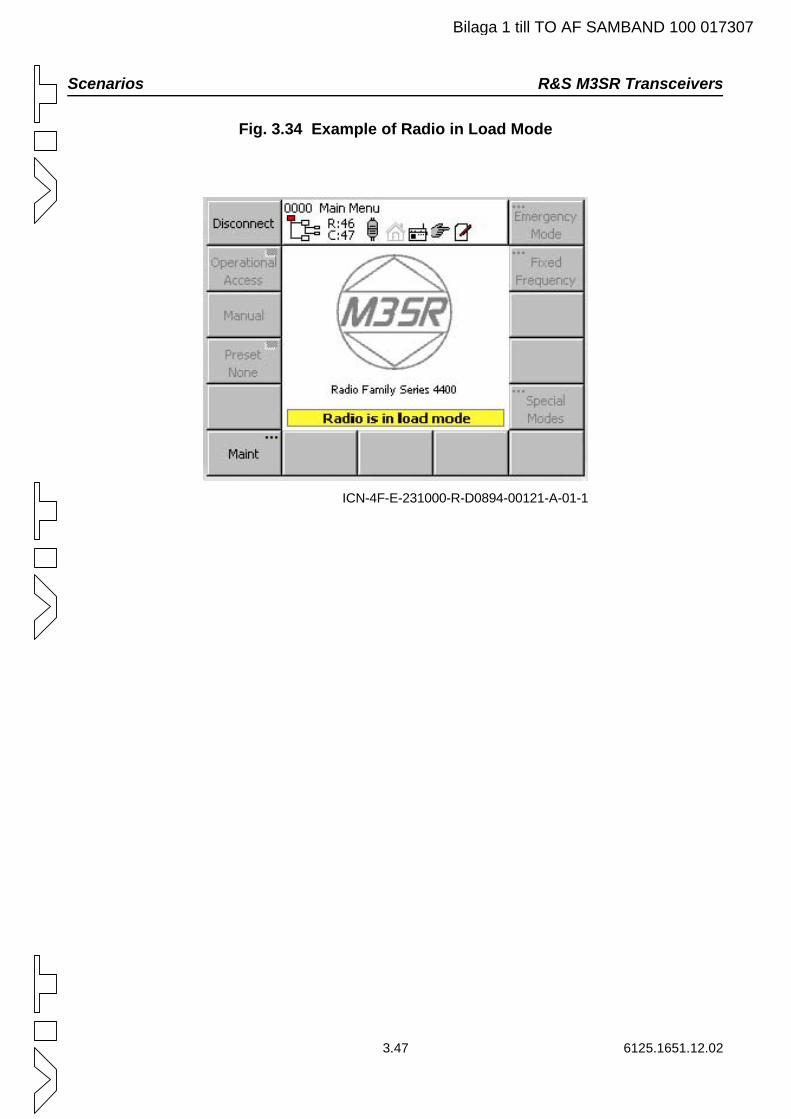
Scenarios R&S M3SR Transceivers
Bilaga 1 till TO AF SAMBAND 100 017307
Fig. 3.34 Example of Radio in Load Mode
ICN-4F-E-231000-R-D0894-00121-A-01-1
3.47 6125.1651.12.02
R&S M3SR Transceivers Waveforms
Bilaga 1 till TO AF SAMBAND 100 017307
3.5 Waveforms
3.5.1 Fixed Frequency
Different waveforms can be integrated in the system. Fixed frequency is the only waveform that is al-ways available. In fixed frequency, only a fix frequency is used for voice and data transfer.
3.5.1.1 Functions
Communication Modes
NOTE:Make sure that for all other communication modes other than voice plain the radio is in re-
mote mode!
The following communication modes are available:
Voice Plain
Voice Ciphered (external cipher unit required, option)
Wideband Analog
Wideband Digital Baseband
Wideband Digital Diphase
Voice Communication Mode
The voice plain communication mode is always available without configuration.
The voice cipher communication mode is available after it has been configured in '1145 Resource Man-agement' menu (see Resource Management) and when an external cipher unit is connected.
Wideband Analog Communication Mode
The wideband analog communication mode must first be configured in the resource management.
This mode is used for wideband AM and FM communication with analog data terminals. Wideband au-dio lines (WB1, WB2) are configurable.
Wideband Digital Baseband and Wideband Digital Diphase Communication Modes
The wideband digital baseband and wideband digital diphase communication modes must first be con-figured in the resource management.
These modes are used for data communication with digital data terminals (baseband and diphase).
6125.1651.12.02 3.48
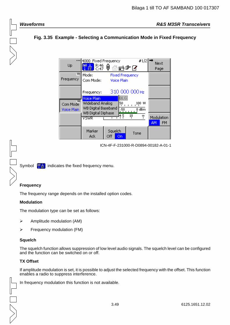
Waveforms R&S M3SR Transceivers
Bilaga 1 till TO AF SAMBAND 100 017307
Fig. 3.35 Example - Selecting a Communication Mode in Fixed Frequency
Symbol indicates the fixed frequency menu.
Frequency
The frequency range depends on the installed option codes.
Modulation
The modulation type can be set as follows:
Amplitude modulation (AM)
Frequency modulation (FM)
Squelch
The squelch function allows suppression of low level audio signals. The squelch level can be configured and the function can be switched on or off.
TX Offset
If amplitude modulation is set, it is possible to adjust the selected frequency with the offset. This function enables a radio to suppress interference.
In frequency modulation this function is not available.
ICN-4F-F-231000-R-D0894-00182-A-01-1
3.49 6125.1651.12.02
R&S M3SR Transceivers Waveforms
Bilaga 1 till TO AF SAMBAND 100 017307
Channel Spacing
The channel spacing can be set to the following values:
8.33 kHz
12.50 kHz
25.00 kHz
25.00 kHz is standard in the UHF band.
Half Duplex Mode
With the half duplex function different frequencies for receiving and transmitting data can be set. This function can be switched on and off.
Clipper
The clipper function enables noise reduction during reception in AM mode. This function can be switched on and off.
Automatic Gain Control
The automatic gain control (AGC) function controls the volume of the loudspeaker and headphone. With this function the volume is set to a constant value. This function can be switched on and off.
NOTE:Only available in AM.
Marker Tone
With the MARKER ACK softkey a generated marker tone can be confirmed. After pressing this softkey the marker tone is suppressed.
Test Tone
With the TONE softkey a test tone (1 kHz) is produced for keying test and monitoring purposes. A tone is generated as long as the softkey is being pressed.
6125.1651.12.02 3.50
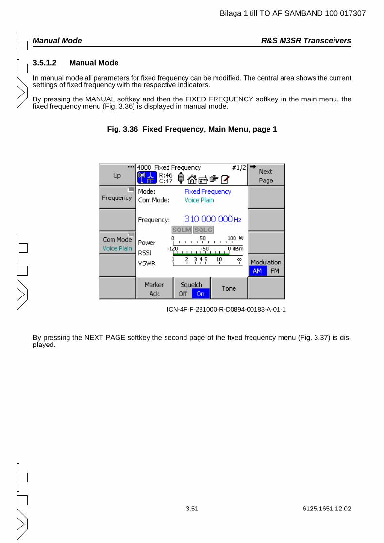
Manual Mode R&S M3SR Transceivers
Bilaga 1 till TO AF SAMBAND 100 017307
3.5.1.2 Manual Mode
In manual mode all parameters for fixed frequency can be modified. The central area shows the current settings of fixed frequency with the respective indicators.
By pressing the MANUAL softkey and then the FIXED FREQUENCY softkey in the main menu, the fixed frequency menu (Fig. 3.36) is displayed in manual mode.
Fig. 3.36 Fixed Frequency, Main Menu, page 1
By pressing the NEXT PAGE softkey the second page of the fixed frequency menu (Fig. 3.37) is dis-played.
ICN-4F-F-231000-R-D0894-00183-A-01-1
3.51 6125.1651.12.02
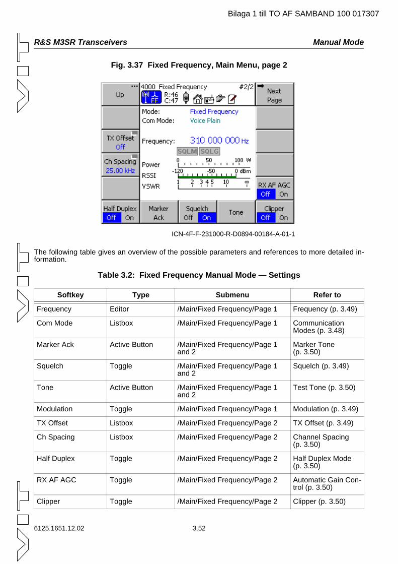
R&S M3SR Transceivers Manual Mode
Bilaga 1 till TO AF SAMBAND 100 017307
Fig. 3.37 Fixed Frequency, Main Menu, page 2
The following table gives an overview of the possible parameters and references to more detailed in-formation.
Table 3.2: Fixed Frequency Manual Mode — Settings
Softkey Type Submenu Refer to
Frequency Editor /Main/Fixed Frequency/Page 1 Frequency (p. 3.49)
Com Mode Listbox /Main/Fixed Frequency/Page 1 Communication Modes (p. 3.48)
Marker Ack Active Button /Main/Fixed Frequency/Page 1 and 2
Marker Tone (p. 3.50)
Squelch Toggle /Main/Fixed Frequency/Page 1 and 2
Squelch (p. 3.49)
Tone Active Button /Main/Fixed Frequency/Page 1 and 2
Test Tone (p. 3.50)
Modulation Toggle /Main/Fixed Frequency/Page 1 Modulation (p. 3.49)
TX Offset Listbox /Main/Fixed Frequency/Page 2 TX Offset (p. 3.49)
Ch Spacing Listbox /Main/Fixed Frequency/Page 2 Channel Spacing (p. 3.50)
Half Duplex Toggle /Main/Fixed Frequency/Page 2 Half Duplex Mode (p. 3.50)
RX AF AGC Toggle /Main/Fixed Frequency/Page 2 Automatic Gain Con-trol (p. 3.50)
Clipper Toggle /Main/Fixed Frequency/Page 2 Clipper (p. 3.50)
ICN-4F-F-231000-R-D0894-00184-A-01-1
6125.1651.12.02 3.52
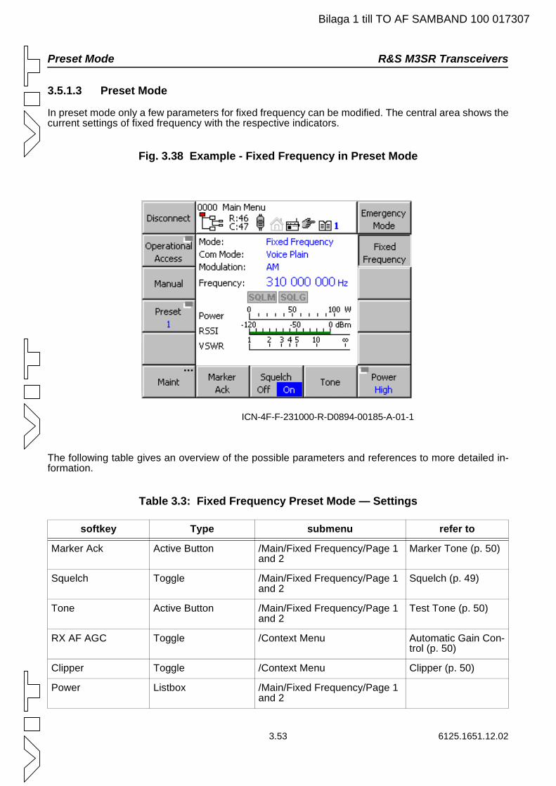
Preset Mode R&S M3SR Transceivers
3.53 6125.1651.12.02
3.5.1.3 Preset Mode
In preset mode only a few parameters for fixed frequency can be modified. The central area shows the current settings of fixed frequency with the respective indicators.
Fig. 3.38 Example - Fixed Frequency in Preset Mode
The following table gives an overview of the possible parameters and references to more detailed in-formation.
Table 3.3: Fixed Frequency Preset Mode — Settings
softkey Type submenu refer to
Marker Ack Active Button /Main/Fixed Frequency/Page 1 and 2
Marker Tone (p. 50)
Squelch Toggle /Main/Fixed Frequency/Page 1 and 2
Squelch (p. 49)
Tone Active Button /Main/Fixed Frequency/Page 1 and 2
Test Tone (p. 50)
RX AF AGC Toggle /Context Menu Automatic Gain Con-trol (p. 50)
Clipper Toggle /Context Menu Clipper (p. 50)
Power Listbox /Main/Fixed Frequency/Page 1 and 2
ICN-4F-F-231000-R-D0894-00185-A-01-1
Bilaga 1 till TO AF SAMBAND 100 017307
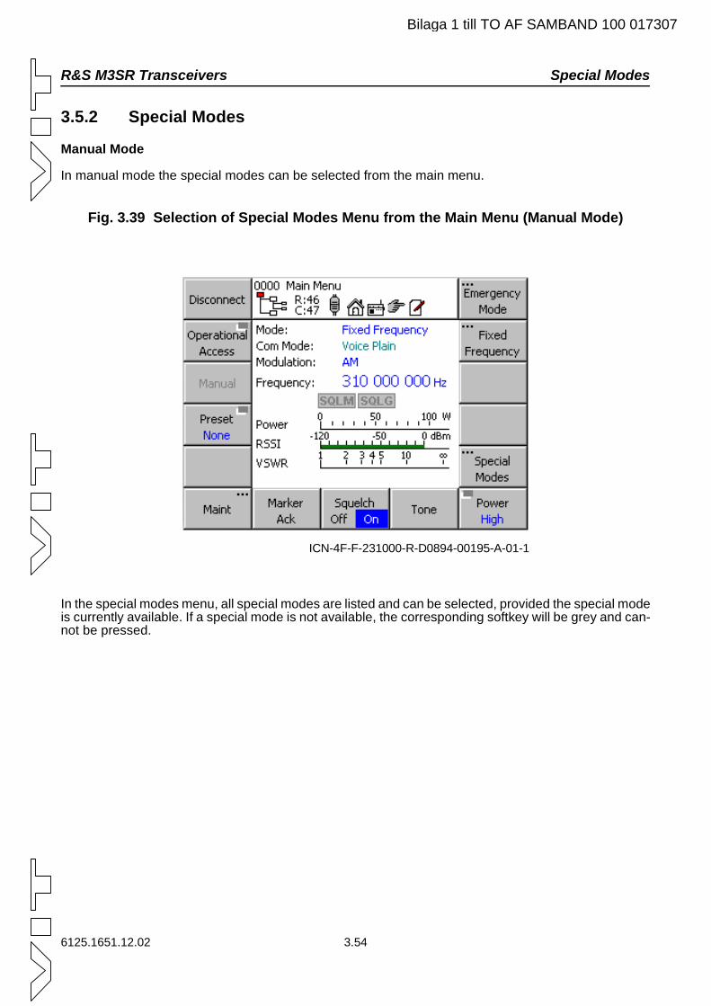
R&S M3SR Transceivers Special Modes
Bilaga 1 till TO AF SAMBAND 100 017307
3.5.2 Special Modes
Manual Mode
In manual mode the special modes can be selected from the main menu.
Fig. 3.39 Selection of Special Modes Menu from the Main Menu (Manual Mode)
In the special modes menu, all special modes are listed and can be selected, provided the special mode is currently available. If a special mode is not available, the corresponding softkey will be grey and can-not be pressed.
ICN-4F-F-231000-R-D0894-00195-A-01-1
6125.1651.12.02 3.54
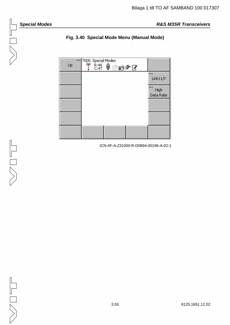
Special Modes R&S M3SR Transceivers
Bilaga 1 till TO AF SAMBAND 100 017307
Fig. 3.40 Special Mode Menu (Manual Mode)
ICN-4F-A-231000-R-D0894-00196-A-02-1
3.55 6125.1651.12.02
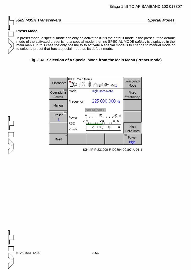
R&S M3SR Transceivers Special Modes
Bilaga 1 till TO AF SAMBAND 100 017307
Preset Mode
In preset mode, a special mode can only be activated if it is the default mode in the preset. If the default mode of the activated preset is not a special mode, then no SPECIAL MODE softkey is displayed in the main menu. In this case the only possibility to activate a special mode is to change to manual mode or to select a preset that has a special mode as its default mode.
Fig. 3.41 Selection of a Special Mode from the Main Menu (Preset Mode)
ICN-4F-F-231000-R-D0894-00197-A-01-1
6125.1651.12.02 3.56
Link11 / LinkY R&S M3SR Transceivers
Bilaga 1 till TO AF SAMBAND 100 017307
3.5.2.1 Link11 / LinkY
NOTE:Make sure that the radio is in remote mode!
3.5.2.1.1 Introduction
Modern transceivers must be able to play a variety of roles in a communication scenario (multirole ra-dio). Therefore a variety of operating modes can be selected and activated depending on the task at hand.
Mode Link11/ LinkY is designed for operation on high-frequency (HF) ground wave and can also oper-ate in the UHF band. The UHF range (225 to 399.975 MHz) is used for LOS (line of sight) connections between stations on the ground, ships and aircrafts.
The Link11 / LinkY data terminal set (DTS) interfaces a tactical data system (TDS) via an optional en-cryption device. Formatted data for the DTS is generated in the TDS computer to transfer data in Link11 / LinkY data format to a UHF transceiver. The transceiver receives the data signal via the narrow band interface, processes the signal and radiates it in the UHF band. The DTS, TDS and the encryption de-vice are third-party equipment.
The Link11 / LinkY waveform is a non-hopping waveform. R&S M3SR radios with activated Link11 / LinkY mode comply with the applicable standard STANAG 5511.
The following preconditions must be fulfilled for Link11 / LinkY operation of R&S M3SR radios:
The radio employed must be a transceiver capable of the UHF or full frequency range.
The Link11 / LinkY option must be installed.
To configure the transceiver accordingly, Link11 / LinkY must be selected in the resource man-agement.
The radio must be connected to the DTS according to Fig. 3.42.
3.57 6125.1651.12.02
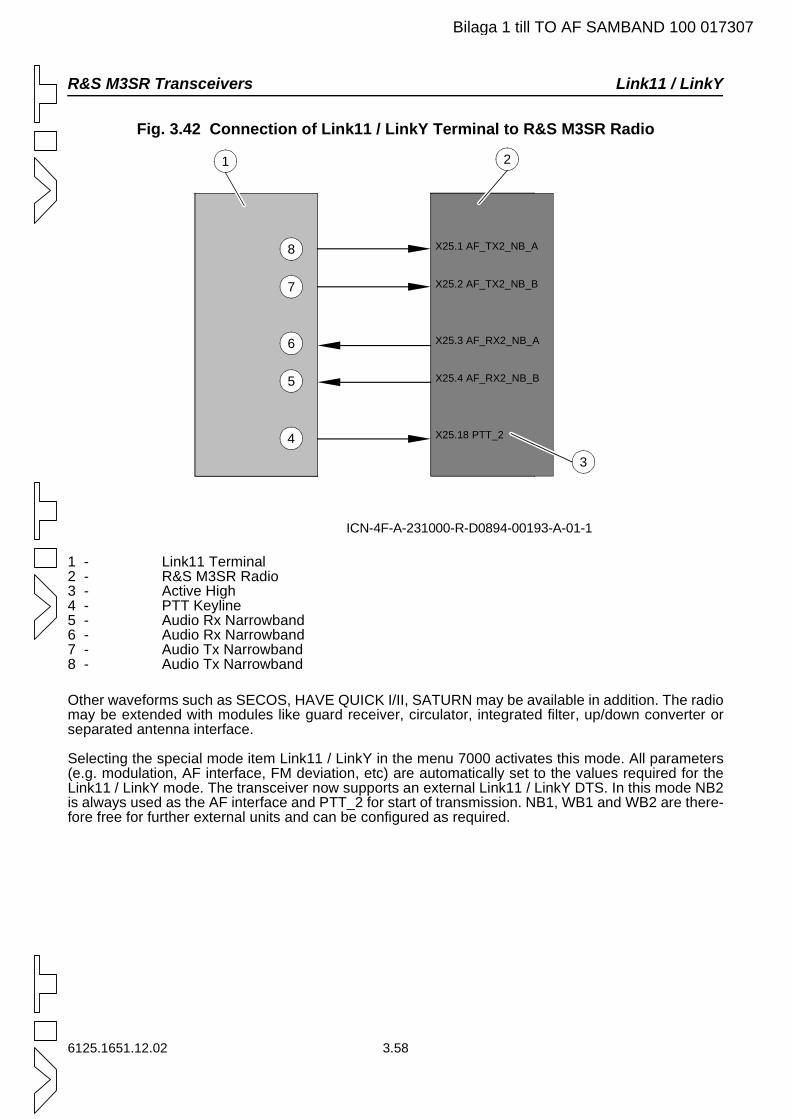
R&S M3SR Transceivers Link11 / LinkY
Bilaga 1 till TO AF SAMBAND 100 017307
Fig. 3.42 Connection of Link11 / LinkY Terminal to R&S M3SR Radio
1 - Link11 Terminal2 - R&S M3SR Radio3 - Active High4 - PTT Keyline5 - Audio Rx Narrowband6 - Audio Rx Narrowband7 - Audio Tx Narrowband8 - Audio Tx Narrowband
Other waveforms such as SECOS, HAVE QUICK I/II, SATURN may be available in addition. The radio may be extended with modules like guard receiver, circulator, integrated filter, up/down converter or separated antenna interface.
Selecting the special mode item Link11 / LinkY in the menu 7000 activates this mode. All parameters (e.g. modulation, AF interface, FM deviation, etc) are automatically set to the values required for the Link11 / LinkY mode. The transceiver now supports an external Link11 / LinkY DTS. In this mode NB2 is always used as the AF interface and PTT_2 for start of transmission. NB1, WB1 and WB2 are there-fore free for further external units and can be configured as required.
ICN-4F-A-231000-R-D0894-00193-A-01-1
1 2
X25.1 AF_TX2_NB_A
X25.2 AF_TX2_NB_B
X25.3 AF_RX2_NB_A
X25.4 AF_RX2_NB_B
X25.18 PTT_2
3
6
7
8
4
5
6125.1651.12.02 3.58
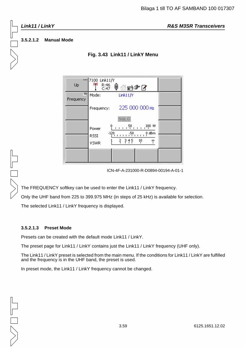
Link11 / LinkY R&S M3SR Transceivers
Bilaga 1 till TO AF SAMBAND 100 017307
3.5.2.1.2 Manual Mode
Fig. 3.43 Link11 / LinkY Menu
The FREQUENCY softkey can be used to enter the Link11 / LinkY frequency.
Only the UHF band from 225 to 399.975 MHz (in steps of 25 kHz) is available for selection.
The selected Link11 / LinkY frequency is displayed.
3.5.2.1.3 Preset Mode
Presets can be created with the default mode Link11 / LinkY.
The preset page for Link11 / LinkY contains just the Link11 / LinkY frequency (UHF only).
The Link11 / LinkY preset is selected from the main menu. If the conditions for Link11 / LinkY are fulfilled and the frequency is in the UHF band, the preset is used.
In preset mode, the Link11 / LinkY frequency cannot be changed.
ICN-4F-A-231000-R-D0894-00194-A-01-1
3.59 6125.1651.12.02
R&S M3SR Transceivers High Data Rate
Bilaga 1 till TO AF SAMBAND 100 017307
3.5.2.2 High Data Rate
NOTE:Make sure that the radio is in remote mode!
3.5.2.2.1 Introduction
With the special mode high data rate (= HDR) the R&S M3SR radio can be used for high speed data communication of several hundred kbit/s over the UHF band.
The functions of modulation, channel coding, FEC and transmit control (Tx/Rx) are performed within suitable external modems, which provide an IF signal interface of 70 MHz. The occupied bandwidth may be up to 300 kHz, depending on the hardware model.
The functions of up/down conversion of the IF signal to the UHF band (225 MHz to 399.975 MHz) with control of transmitter power and receiver gain are performed within the R&S M3SR radio, which has to be equipped with the module Up/Down Converter R&S UX 4401. This special mode is provided only in simplex, fixed frequency (FF) operation. The converter is designed for stationary or maritime applica-tions and burst transmissions (TDMA channel access), enabling interoperability with several proprietary external modems.
The R&S UX 4401 may be integrated in the factory or added by installing the HDR Upgrade Kit R&S UX 4401-U. The converter can be combined with other radio modules such as Guard Receiver R&S ET 4400G, separate Antenna Interface R&S GI 4403, circulator, integrated filter R&S FD 4430 or hop-ping processor. Therefore it can be added to all R&S M3SR transceiver versions with or without Link11/LinkY option. In contrast to the special mode Link11 / LinkY, the HDR mode does not require an option code.
HDR cannot be used in VHF only radios (VHF option installed) or receiver/transmitter only configura-tions (ET.. / ST..).
When the radio is operated in the HDR mode, then the power is fixed for the power levels high/medium/low to ensure a high quality transmit signal with waveforms requesting a high crest factor. If an external amplifier is connected, this amplifier is set to bypass to avoid degradation of linearity caused by the ex-ternal amplifier.
External filters like R&S FT 213A or R&S FD 430 are supported as in fixed frequency mode.
In the case that the radio is operated in modes other than HDR, the Converter R&S UX 4401 is switched to bypass and the other modules are processing the waveform.
Requirements for using HDR:
The radio is a transceiver (XT.. / XD..).
The UHF frequency band can be used (option UHF or full frequency).
The Up/Down Converter R&S UX 4401 is installed.
The following preparations have to be made to use HDR:
The external modem has to be connected according to Fig. 3.44.
R&S UX 4401 has to be configured according to the modem/waveform requirements.
PTT resource has to be selected and HDR has to be activated.
Radio has to be set to remote mode.
6125.1651.12.02 3.60
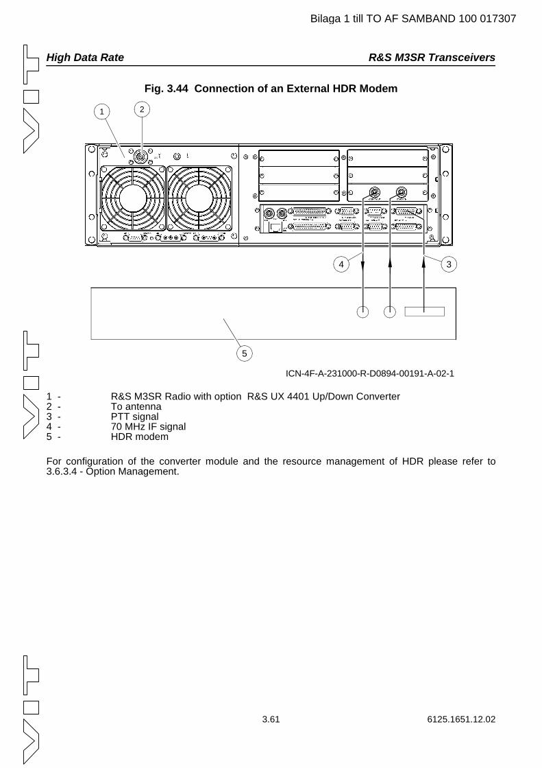
High Data Rate R&S M3SR Transceivers
Bilaga 1 till TO AF SAMBAND 100 017307
Fig. 3.44 Connection of an External HDR Modem
1 - R&S M3SR Radio with option R&S UX 4401 Up/Down Converter2 - To antenna3 - PTT signal4 - 70 MHz IF signal5 - HDR modem
For configuration of the converter module and the resource management of HDR please refer to 3.6.3.4 - Option Management.
ICN-4F-A-231000-R-D0894-00191-A-02-1
1
34
5
2
3.61 6125.1651.12.02
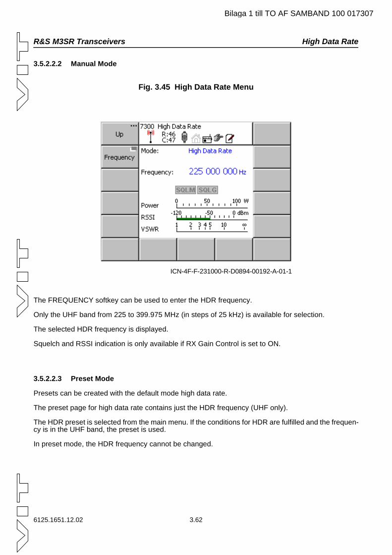
R&S M3SR Transceivers High Data Rate
Bilaga 1 till TO AF SAMBAND 100 017307
3.5.2.2.2 Manual Mode
Fig. 3.45 High Data Rate Menu
The FREQUENCY softkey can be used to enter the HDR frequency.
Only the UHF band from 225 to 399.975 MHz (in steps of 25 kHz) is available for selection.
The selected HDR frequency is displayed.
Squelch and RSSI indication is only available if RX Gain Control is set to ON.
3.5.2.2.3 Preset Mode
Presets can be created with the default mode high data rate.
The preset page for high data rate contains just the HDR frequency (UHF only).
The HDR preset is selected from the main menu. If the conditions for HDR are fulfilled and the frequen-cy is in the UHF band, the preset is used.
In preset mode, the HDR frequency cannot be changed.
ICN-4F-F-231000-R-D0894-00192-A-01-1
6125.1651.12.02 3.62
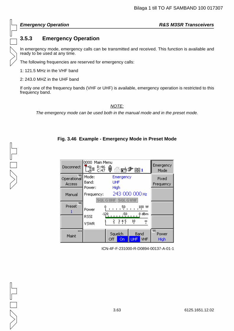
Emergency Operation R&S M3SR Transceivers
Bilaga 1 till TO AF SAMBAND 100 017307
3.5.3 Emergency Operation
In emergency mode, emergency calls can be transmitted and received. This function is available and ready to be used at any time.
The following frequencies are reserved for emergency calls:
1: 121.5 MHz in the VHF band
2: 243.0 MHZ in the UHF band
If only one of the frequency bands (VHF or UHF) is available, emergency operation is restricted to this frequency band.
NOTE:The emergency mode can be used both in the manual mode and in the preset mode.
Fig. 3.46 Example - Emergency Mode in Preset Mode
ICN-4F-F-231000-R-D0894-00137-A-01-1
3.63 6125.1651.12.02
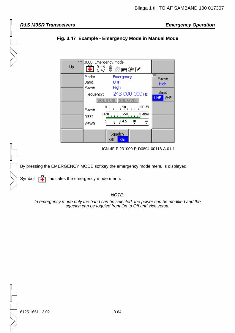
R&S M3SR Transceivers Emergency Operation
Bilaga 1 till TO AF SAMBAND 100 017307
Fig. 3.47 Example - Emergency Mode in Manual Mode
By pressing the EMERGENCY MODE softkey the emergency mode menu is displayed.
Symbol indicates the emergency mode menu.
NOTE:In emergency mode only the band can be selected, the power can be modified and the
squelch can be toggled from On to Off and vice versa.
ICN-4F-F-231000-R-D0894-00118-A-01-1
6125.1651.12.02 3.64
Preset Scan Mode R&S M3SR Transceivers
Bilaga 1 till TO AF SAMBAND 100 017307
3.5.4 Preset Scan Mode
3.5.4.1 Introduction
Preset Scan is used to check if traffic is going on in selected radio channels (including EPM channels). As a result only a limited number of radios is necessary to monitor several channels. The user can enter a start and an end preset number (softkeys BEGIN SCAN and END SCAN) to define a range of preset numbers between 0 and 199, which are successively and cyclically activated when preset scan is start-ed. The Search Time parameter (softkey SEARCH) defines how long the radio shall remain on the se-lected preset and wait for a signal until the next preset in the list is activated if no signal is detected. Any search time in the range between 1 s and 60 s can be set. The preset scan stops and the radio remains on the currently active preset when a signal above the squelch threshold (or synchronisation sequence in EPM modes) is detected or when the user deliberately deactivates the preset scan by pressing STOP SCAN or leaving the menu. As for manual preset activation, preset scan uses the currently selected preset domain. Selecting the domain for preset scanning is not possible in the PRESET SCAN menu, for this enter the MAINTENANCE menu (softkey ACTIVE DOM).
When preset scan has stopped because a busy channel was detected, the parameter Auto Continue (softkey AUTO CONT) determines if and after what time the radio shall automatically continue scanning after the squelch (or synchronisation) has become inactive. The Auto Continue function can be switched off or adjusted between 10 and 60 seconds in 10-s increments. When Auto Continue is off, the radio always remains on the busy preset channel, even if the signal is no longer present.
In addition, the preset scan menu shows the last found busy preset channel. This preset can be acti-vated by softkey. If this is done while scanning is in progress, scanning automatically stops and the pre-set where the squelch (or synchronisation) was detected is activated.
For scanning only those presets are considered which are contained in the list of active presets. The radio attempts to activate the preset with its default page. If this fails, it moves on to the next preset. Only the default pages of the presets are activated, switching to another page is not possible. Error messages to indicate that there are no presets in the defined range (gaps) or that a preset could not be activated (e.g. due to invalid parameters in the preset) are not produced in preset scan mode. The radio simply tries to activate the next preset.
When preset scan is stopped the currently selected preset remains active. To resume scanning there are two possibilities: Continue Scan or Start Scan. After power-up only Start Scan is possible. If preset scan has already been active since the radio was last powered up, scanning may be resumed with CONTINUE SCAN. For Start Scan and Continue Scan the set parameters are used. If due to a param-eter change the next preset to be activated is out of the range defined with BEGIN SCAN and END SCAN, scanning resumes with the preset that was set with BEGIN SCAN, so this is equivalent to Start Scan.
When PTT is set while scan is running, the scan process is stopped.
Reception of a guard receiver signal during preset scan is indicated by the SQL G LED on the front panel of the radio, by the G LED on the control unit and by the SQLG indicator in the preset scan menu. When a guard receiver signal is detected, key Menu/Home can be used to change to the main menu and from there to emergency mode to answer the emergency call.
Conditions where an ongoing preset scan is stopped:
Detection of a busy channel (squelch or sync)
Use of softkey STOP SCAN or GP2PP command
Leaving the menu
Loss of connection to control unit or remote client which started the scan process
3.65 6125.1651.12.02
R&S M3SR Transceivers Preset Scan Mode
Bilaga 1 till TO AF SAMBAND 100 017307
Loss of operational access rights of control unit or remote client which started the scan process
Change of local/remote status of the radio
Change of presets (adding, removing, editing, manually activating a preset or selecting manual operation, changing the preset page, changing the domain)
Use of signal LAST SIGNAL or GB2PP command
Activation of PTT
All preset scan parameters are stored, so when the radio is powered down and up again, scanning can be started with the stored parameters.
Initial values of scan parameters when the radio is started up the very first time or when the memory is reset:
Begin Scan: first preset in the list, 0 and deactivated if list is empty
End Scan: last preset in the list, 199 and deactivated if list is empty
Search Time: 1 s
Auto Continue: Off
6125.1651.12.02 3.66
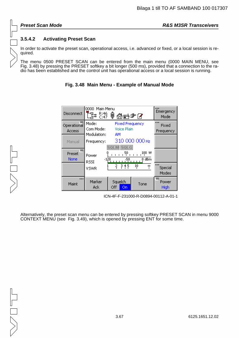
Preset Scan Mode R&S M3SR Transceivers
Bilaga 1 till TO AF SAMBAND 100 017307
3.5.4.2 Activating Preset Scan
In order to activate the preset scan, operational access, i.e. advanced or fixed, or a local session is re-quired.
The menu 0500 PRESET SCAN can be entered from the main menu (0000 MAIN MENU, see Fig. 3.48) by pressing the PRESET softkey a bit longer (500 ms), provided that a connection to the ra-dio has been established and the control unit has operational access or a local session is running.
Fig. 3.48 Main Menu - Example of Manual Mode
Alternatively, the preset scan menu can be entered by pressing softkey PRESET SCAN in menu 9000 CONTEXT MENU (see Fig. 3.49), which is opened by pressing ENT for some time.
ICN-4F-F-231000-R-D0894-00112-A-01-1
3.67 6125.1651.12.02
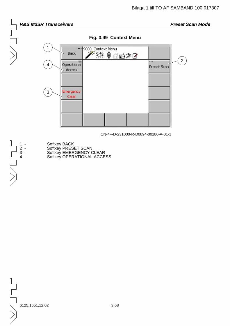
R&S M3SR Transceivers Preset Scan Mode
Bilaga 1 till TO AF SAMBAND 100 017307
Fig. 3.49 Context Menu
1 - Softkey BACK2 - Softkey PRESET SCAN3 - Softkey EMERGENCY CLEAR4 - Softkey OPERATIONAL ACCESS
ICN-4F-D-231000-R-D0894-00180-A-01-1
1
2
3
4
6125.1651.12.02 3.68
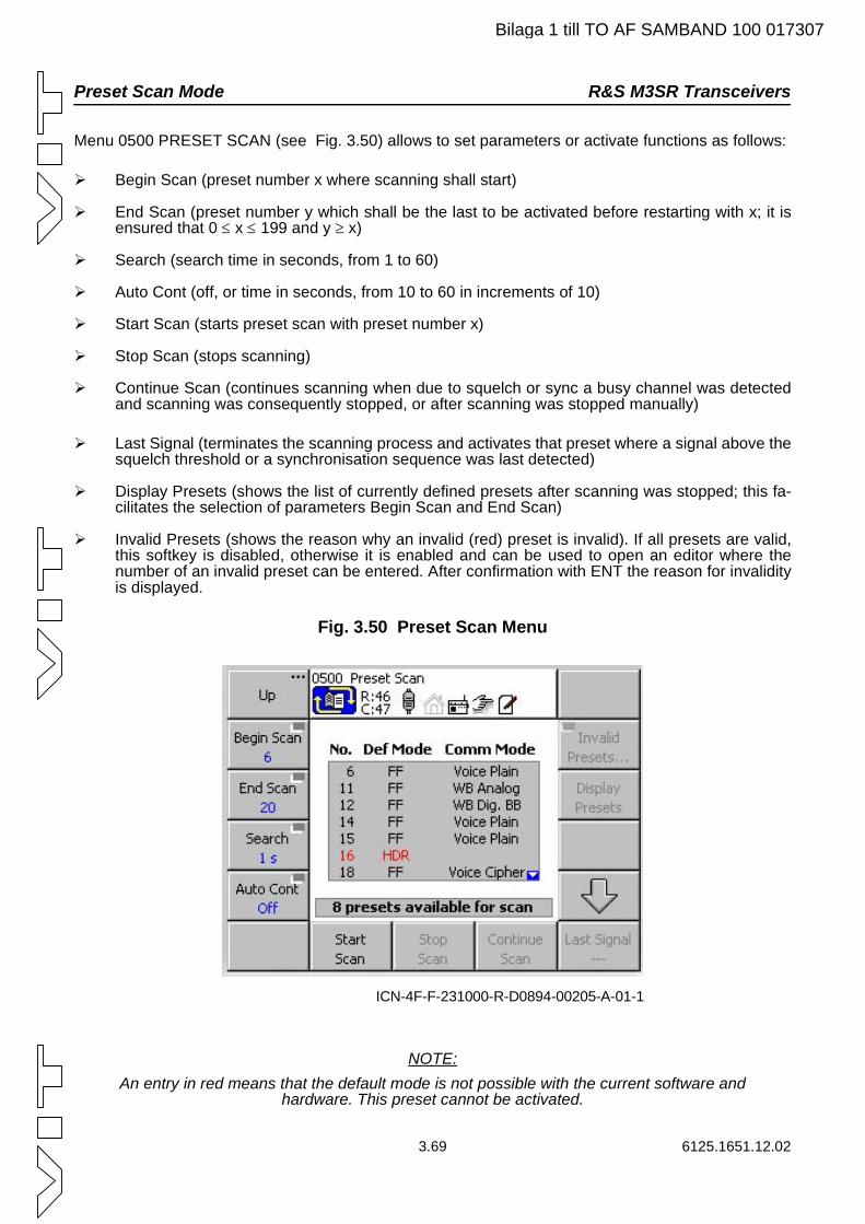
Preset Scan Mode R&S M3SR Transceivers
Bilaga 1 till TO AF SAMBAND 100 017307
Menu 0500 PRESET SCAN (see Fig. 3.50) allows to set parameters or activate functions as follows:
Begin Scan (preset number x where scanning shall start)
End Scan (preset number y which shall be the last to be activated before restarting with x; it is ensured that 0 ≤ x ≤ 199 and y ≥ x)
Search (search time in seconds, from 1 to 60)
Auto Cont (off, or time in seconds, from 10 to 60 in increments of 10)
Start Scan (starts preset scan with preset number x)
Stop Scan (stops scanning)
Continue Scan (continues scanning when due to squelch or sync a busy channel was detected and scanning was consequently stopped, or after scanning was stopped manually)
Last Signal (terminates the scanning process and activates that preset where a signal above the squelch threshold or a synchronisation sequence was last detected)
Display Presets (shows the list of currently defined presets after scanning was stopped; this fa-cilitates the selection of parameters Begin Scan and End Scan)
Invalid Presets (shows the reason why an invalid (red) preset is invalid). If all presets are valid, this softkey is disabled, otherwise it is enabled and can be used to open an editor where the number of an invalid preset can be entered. After confirmation with ENT the reason for invalidity is displayed.
Fig. 3.50 Preset Scan Menu
NOTE:An entry in red means that the default mode is not possible with the current software and
hardware. This preset cannot be activated.
ICN-4F-F-231000-R-D0894-00205-A-01-1
3.69 6125.1651.12.02
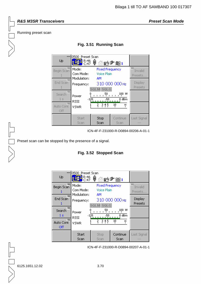
R&S M3SR Transceivers Preset Scan Mode
Bilaga 1 till TO AF SAMBAND 100 017307
Running preset scan
Fig. 3.51 Running Scan
Preset scan can be stopped by the presence of a signal.
Fig. 3.52 Stopped Scan
ICN-4F-F-231000-R-D0894-00206-A-01-1
ICN-4F-F-231000-R-D0894-00207-A-01-1
6125.1651.12.02 3.70
Preset Scan Mode R&S M3SR Transceivers
Bilaga 1 till TO AF SAMBAND 100 017307
3.5.4.3 Limitations of Preset Scan
With multi-application devices delays will occur due to hardware design when switching over e.g. be-tween two EPM applications, since for each change the other application must be loaded to the protec-tion processor. The real time needed to completely scan a selected preset range therefore is composed of the loading time plus the set search time. Where scanning is to be performed on several presets con-taining both EPM application X and EPM application Y, the user can minimise the overall loading time by arranging the presets in such a way that e.g. first all presets of EPM application X are scanned, fol-lowed by all presets of EPM application Y. In this way only two loading processes per scan cycle are required altogether. Loading typically takes approximately 3 seconds before operation can continue.
When the radio is set to local mode, only those presets are included in the scan process which have a voice mode as communication mode, since local mode only supports voice communication. So it may occur that less presets are scanned than in remote mode. No warnings are produced.
When a fill device is connected and load mode becomes active as a result, a running preset scan is stopped. While load mode is active preset scan cannot be started.
Scanning is performed with the parameters defined in the preset. Preset parameters which can be tem-porarily overwritten cannot be changed while scanning is in progress. One possibility, however, is to go to the main menu, thus terminating the preset scan, and to change the modifiable parameters here.
3.71 6125.1651.12.02
R&S M3SR Transceivers Maintenance
Bilaga 1 till TO AF SAMBAND 100 017307
3.6 Maintenance
This chapter describes the maintenance tasks for the radio and for the control unit. Built-in tests allow a comfortable error search in case of malfunction. The radio and the control unit can be adapted to cus-tomer-specific requirements concerning the waveforms and preset values as well as user-specific ad-aptations for daily use. The option management for additional features is also explained.
3.6.1 Control Unit and Radio
All described built-in tests and all configuration procedures can be executed with an internal as well as an external control unit if the radio does not have an integrated control unit. The following description of maintenance tasks does not distinguish between an internal and an external control unit.
3.6.1.1 Troubleshooting
In order to detect device and system errors, built-in tests are implemented in the system. These built-in test functions allow an exact analysis of the system. The results support the service team to make a decision of how to proceed in order to solve the problem. All tests are implemented for both radio and control unit, therefore the information given below generally applies to both units.
3.6.1.1.1 PBIT
The power-on built-in test is performed automatically after the system has been switched on.
3.6.1.1.2 CBIT
Specific parameters of the system are tested continuously. Any errors that have occurred are listed in the error list. The CBIT is started by pressing softkey "CBIT" in menu "1110 Radio Maintenance" (radio) or "1300 Control Unit Maintenance" (control unit).
6125.1651.12.02 3.72
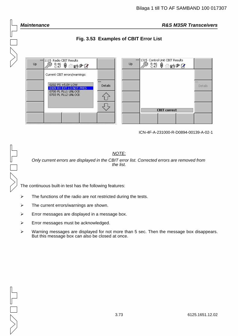
Maintenance R&S M3SR Transceivers
Bilaga 1 till TO AF SAMBAND 100 017307
Fig. 3.53 Examples of CBIT Error List
NOTE:Only current errors are displayed in the CBIT error list. Corrected errors are removed from
the list.
The continuous built-in test has the following features:
The functions of the radio are not restricted during the tests.
The current errors/warnings are shown.
Error messages are displayed in a message box.
Error messages must be acknowledged.
Warning messages are displayed for not more than 5 sec. Then the message box disappears. But this message box can also be closed at once.
ICN-4F-A-231000-R-D0894-00139-A-02-1
3.73 6125.1651.12.02
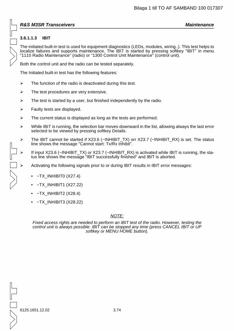
R&S M3SR Transceivers Maintenance
Bilaga 1 till TO AF SAMBAND 100 017307
3.6.1.1.3 IBIT
The initiated built-in test is used for equipment diagnostics (LEDs, modules, wiring..). This test helps to localize failures and supports maintenance. The IBIT is started by pressing softkey "IBIT" in menu "1110 Radio Maintenance" (radio) or "1300 Control Unit Maintenance" (control unit).
Both the control unit and the radio can be tested separately.
The Initiated built-in test has the following features:
The function of the radio is deactivated during this test.
The test procedures are very extensive.
The test is started by a user, but finished independently by the radio.
Faulty tests are displayed.
The current status is displayed as long as the tests are performed.
While IBIT is running, the selection bar moves downward in the list, allowing always the last error selected to be viewed by pressing softkey Details.
The IBIT cannot be started if X23.6 (~INHIBIT_TX) orr X23.7 (~INHIBIT_RX) is set. The status line shows the message "Cannot start: Tx/Rx Inhibit".
If input X23.6 (~INHIBIT_TX) or X23.7 (~INHIBIT_RX) is activated while IBIT is running, the sta-tus line shows the message "IBIT successfully finished" and IBIT is aborted.
Activating the following signals prior to or during IBIT results in IBIT error messages:
• ~TX_INHIBIT0 (X27.4)
• ~TX_INHIBIT1 (X27.22)
• ~TX_INHIBIT2 (X28.4)
• ~TX_INHIBIT3 (X28.22)
NOTE:Fixed access rights are needed to perform an IBIT test of the radio. However, testing the control unit is always possible. IBIT can be stopped any time (press CANCEL IBIT or UP
softkey or MENU HOME button).
6125.1651.12.02 3.74
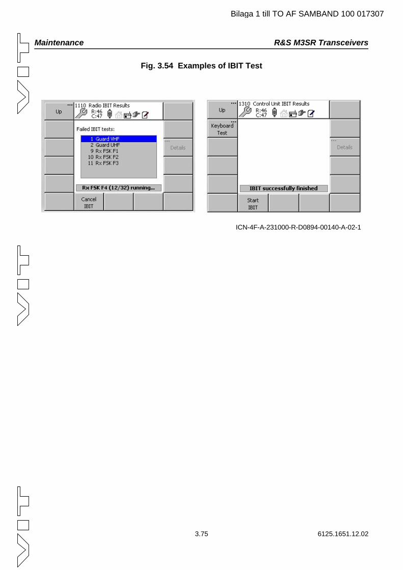
Maintenance R&S M3SR Transceivers
Bilaga 1 till TO AF SAMBAND 100 017307
Fig. 3.54 Examples of IBIT Test
ICN-4F-A-231000-R-D0894-00140-A-02-1
3.75 6125.1651.12.02
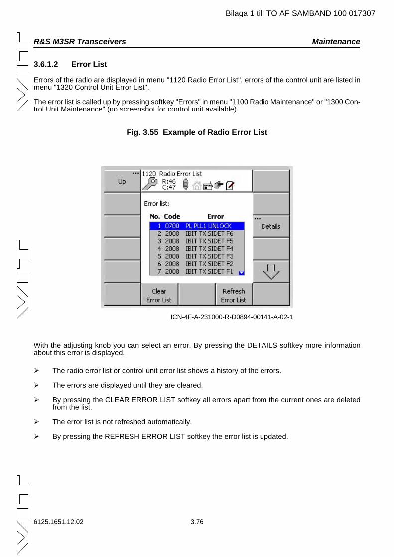
R&S M3SR Transceivers Maintenance
Bilaga 1 till TO AF SAMBAND 100 017307
3.6.1.2 Error List
Errors of the radio are displayed in menu "1120 Radio Error List", errors of the control unit are listed in menu "1320 Control Unit Error List".
The error list is called up by pressing softkey "Errors" in menu "1100 Radio Maintenance" or "1300 Con-trol Unit Maintenance" (no screenshot for control unit available).
Fig. 3.55 Example of Radio Error List
With the adjusting knob you can select an error. By pressing the DETAILS softkey more information about this error is displayed.
The radio error list or control unit error list shows a history of the errors.
The errors are displayed until they are cleared.
By pressing the CLEAR ERROR LIST softkey all errors apart from the current ones are deleted from the list.
The error list is not refreshed automatically.
By pressing the REFRESH ERROR LIST softkey the error list is updated.
ICN-4F-A-231000-R-D0894-00141-A-02-1
6125.1651.12.02 3.76
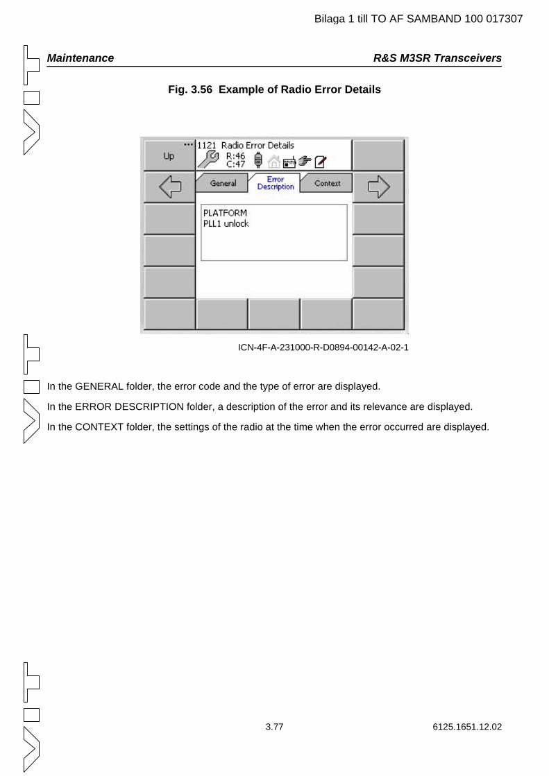
Maintenance R&S M3SR Transceivers
Bilaga 1 till TO AF SAMBAND 100 017307
Fig. 3.56 Example of Radio Error Details
In the GENERAL folder, the error code and the type of error are displayed.
In the ERROR DESCRIPTION folder, a description of the error and its relevance are displayed.
In the CONTEXT folder, the settings of the radio at the time when the error occurred are displayed.
ICN-4F-A-231000-R-D0894-00142-A-02-1
3.77 6125.1651.12.02
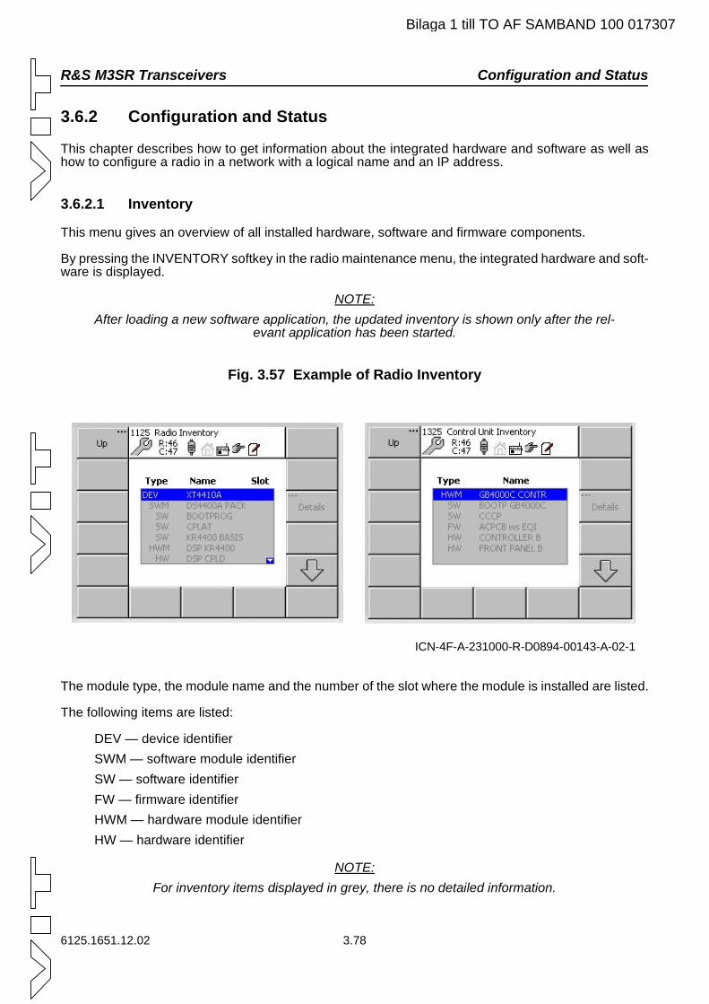
R&S M3SR Transceivers Configuration and Status
Bilaga 1 till TO AF SAMBAND 100 017307
3.6.2 Configuration and Status
This chapter describes how to get information about the integrated hardware and software as well as how to configure a radio in a network with a logical name and an IP address.
3.6.2.1 Inventory
This menu gives an overview of all installed hardware, software and firmware components.
By pressing the INVENTORY softkey in the radio maintenance menu, the integrated hardware and soft-ware is displayed.
NOTE:After loading a new software application, the updated inventory is shown only after the rel-
evant application has been started.
Fig. 3.57 Example of Radio Inventory
The module type, the module name and the number of the slot where the module is installed are listed.
The following items are listed:
DEV — device identifierSWM — software module identifierSW — software identifierFW — firmware identifierHWM — hardware module identifierHW — hardware identifier
NOTE:For inventory items displayed in grey, there is no detailed information.
ICN-4F-A-231000-R-D0894-00143-A-02-1
6125.1651.12.02 3.78
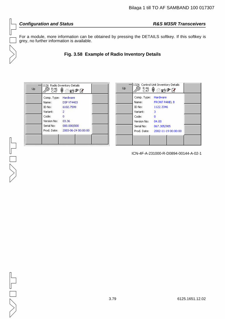
Configuration and Status R&S M3SR Transceivers
Bilaga 1 till TO AF SAMBAND 100 017307
For a module, more information can be obtained by pressing the DETAILS softkey. If this softkey is grey, no further information is available.
Fig. 3.58 Example of Radio Inventory Details
ICN-4F-A-231000-R-D0894-00144-A-02-1
3.79 6125.1651.12.02
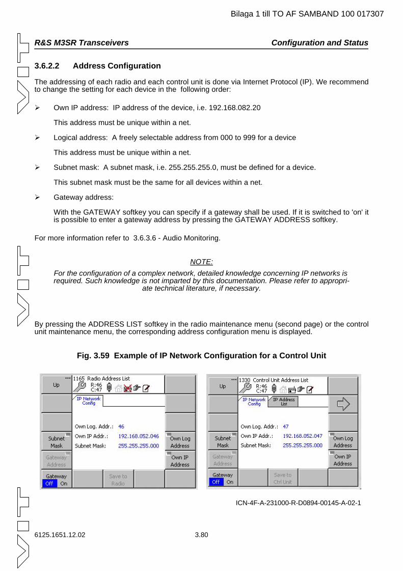
R&S M3SR Transceivers Configuration and Status
Bilaga 1 till TO AF SAMBAND 100 017307
3.6.2.2 Address Configuration
The addressing of each radio and each control unit is done via Internet Protocol (IP). We recommend to change the setting for each device in the following order:
Own IP address: IP address of the device, i.e. 192.168.082.20
This address must be unique within a net.
Logical address: A freely selectable address from 000 to 999 for a device
This address must be unique within a net.
Subnet mask: A subnet mask, i.e. 255.255.255.0, must be defined for a device.
This subnet mask must be the same for all devices within a net.
Gateway address:
With the GATEWAY softkey you can specify if a gateway shall be used. If it is switched to 'on' it is possible to enter a gateway address by pressing the GATEWAY ADDRESS softkey.
For more information refer to 3.6.3.6 - Audio Monitoring.
NOTE:For the configuration of a complex network, detailed knowledge concerning IP networks is required. Such knowledge is not imparted by this documentation. Please refer to appropri-
ate technical literature, if necessary.
By pressing the ADDRESS LIST softkey in the radio maintenance menu (second page) or the control unit maintenance menu, the corresponding address configuration menu is displayed.
Fig. 3.59 Example of IP Network Configuration for a Control Unit
ICN-4F-A-231000-R-D0894-00145-A-02-1
6125.1651.12.02 3.80
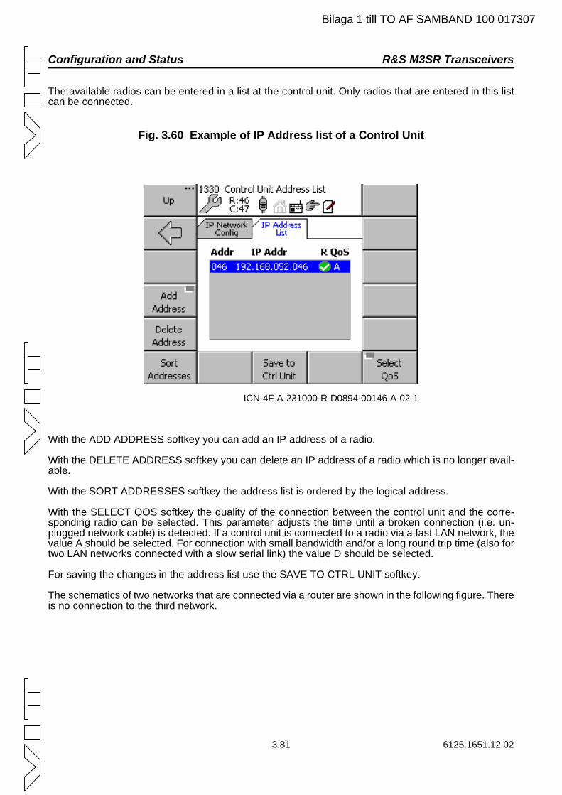
Configuration and Status R&S M3SR Transceivers
Bilaga 1 till TO AF SAMBAND 100 017307
The available radios can be entered in a list at the control unit. Only radios that are entered in this list can be connected.
Fig. 3.60 Example of IP Address list of a Control Unit
With the ADD ADDRESS softkey you can add an IP address of a radio.
With the DELETE ADDRESS softkey you can delete an IP address of a radio which is no longer avail-able.
With the SORT ADDRESSES softkey the address list is ordered by the logical address.
With the SELECT QOS softkey the quality of the connection between the control unit and the corre-sponding radio can be selected. This parameter adjusts the time until a broken connection (i.e. un-plugged network cable) is detected. If a control unit is connected to a radio via a fast LAN network, the value A should be selected. For connection with small bandwidth and/or a long round trip time (also for two LAN networks connected with a slow serial link) the value D should be selected.
For saving the changes in the address list use the SAVE TO CTRL UNIT softkey.
The schematics of two networks that are connected via a router are shown in the following figure. There is no connection to the third network.
ICN-4F-A-231000-R-D0894-00146-A-02-1
3.81 6125.1651.12.02
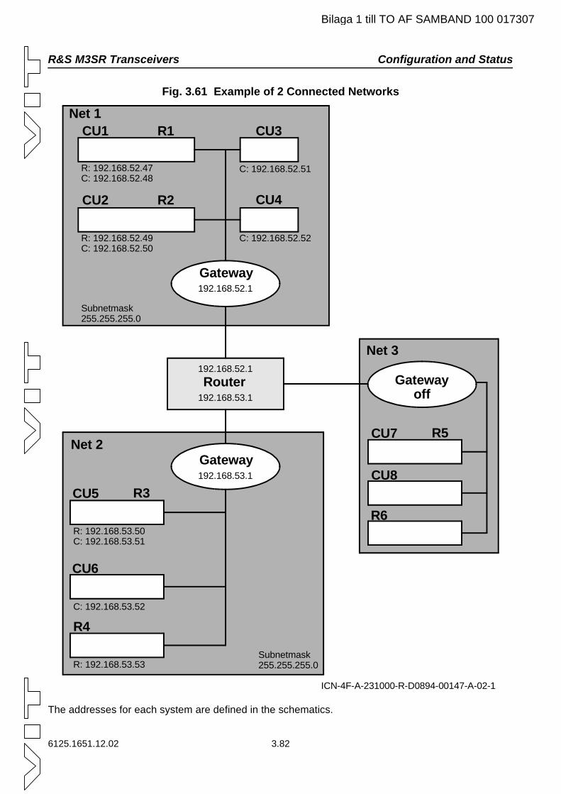
R&S M3SR Transceivers Configuration and Status
Bilaga 1 till TO AF SAMBAND 100 017307
Fig. 3.61 Example of 2 Connected Networks
The addresses for each system are defined in the schematics.
ICN-4F-A-231000-R-D0894-00147-A-02-1
CU1 R1 CU3
CU4
R: 192.168.52.47C: 192.168.52.48
CU2 R2
R: 192.168.52.49C: 192.168.52.50
192.168.52.1
C: 192.168.52.52
C: 192.168.52.51
Subnetmask255.255.255.0
Gateway
192.168.52.1
192.168.53.1
Net 2
CU5
R: 192.168.53.50C: 192.168.53.51
R3192.168.53.1Gateway
CU6
R4C: 192.168.53.52
R: 192.168.53.53Subnetmask255.255.255.0
Net 1
Router Gatewayoff
CU7 R5
CU8
R6
Net 3
6125.1651.12.02 3.82
Configuration and Status R&S M3SR Transceivers
Bilaga 1 till TO AF SAMBAND 100 017307
Some possible connections are:
The control unit CU1 (net 1) is connected to radio R2 (net 1) within net 1.
The control unit CU4 (net 1) is connected to radio R1 (net 1) within net 1.
The control unit CU2 (net 1) is connected to radio R4 (net 2) via a router.
The control unit CU6 (net 2) is connected to radio R1 (net 1) via a router.
A connection to net 3 is not possible because the gateway is not set in this net.
3.83 6125.1651.12.02
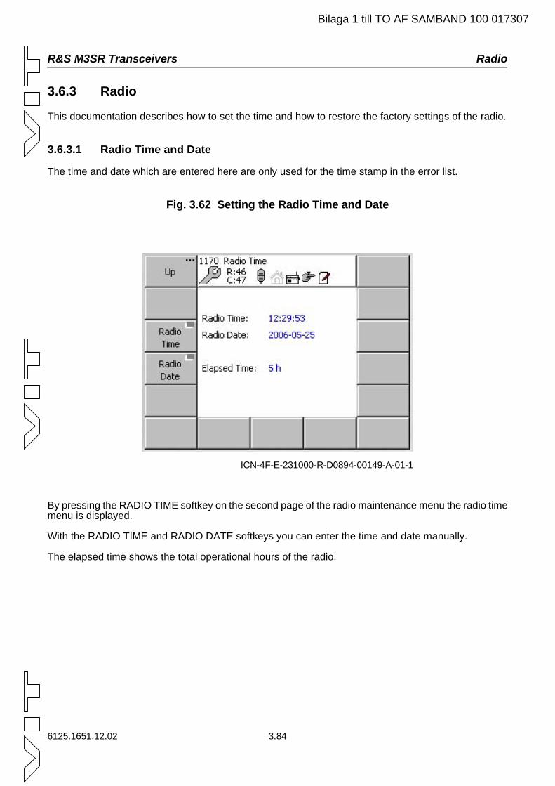
R&S M3SR Transceivers Radio
6125.1651.12.02 3.84
3.6.3 Radio
This documentation describes how to set the time and how to restore the factory settings of the radio.
3.6.3.1 Radio Time and Date
The time and date which are entered here are only used for the time stamp in the error list.
Fig. 3.62 Setting the Radio Time and Date
By pressing the RADIO TIME softkey on the second page of the radio maintenance menu the radio time menu is displayed.
With the RADIO TIME and RADIO DATE softkeys you can enter the time and date manually.
The elapsed time shows the total operational hours of the radio.
ICN-4F-E-231000-R-D0894-00149-A-01-1
Bilaga 1 till TO AF SAMBAND 100 017307
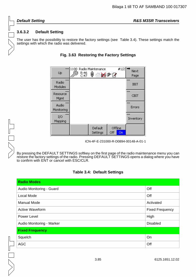
Default Setting R&S M3SR Transceivers
Bilaga 1 till TO AF SAMBAND 100 017307
3.6.3.2 Default Setting
The user has the possibility to restore the factory settings (see Table 3.4). These settings match the settings with which the radio was delivered.
Fig. 3.63 Restoring the Factory Settings
By pressing the DEFAULT SETTINGS softkey on the first page of the radio maintenance menu you can restore the factory settings of the radio. Pressing DEFAULT SETTINGS opens a dialog where you have to confirm with ENT or cancel with ESC/CLR.
Table 3.4: Default Settings
Radio Modes
Audio Monitoring - Guard Off
Local Mode Off
Manual Mode Activated
Active Waveform Fixed Frequency
Power Level High
Audio Monitoring - Marker Disabled
Fixed Frequency
Squelch On
AGC Off
ICN-4F-E-231000-R-D0894-00148-A-01-1
3.85 6125.1651.12.02
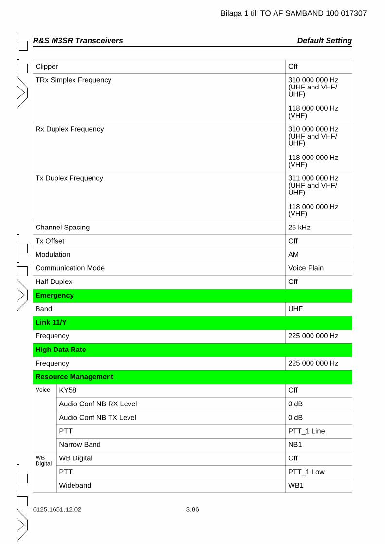
R&S M3SR Transceivers Default Setting
Bilaga 1 till TO AF SAMBAND 100 017307
Clipper Off
TRx Simplex Frequency 310 000 000 Hz (UHF and VHF/UHF)
118 000 000 Hz (VHF)
Rx Duplex Frequency 310 000 000 Hz (UHF and VHF/UHF)
118 000 000 Hz (VHF)
Tx Duplex Frequency 311 000 000 Hz (UHF and VHF/UHF)
118 000 000 Hz (VHF)
Channel Spacing 25 kHz
Tx Offset Off
Modulation AM
Communication Mode Voice Plain
Half Duplex Off
Emergency
Band UHF
Link 11/Y
Frequency 225 000 000 Hz
High Data Rate
Frequency 225 000 000 Hz
Resource Management
Voice KY58 Off
Audio Conf NB RX Level 0 dB
Audio Conf NB TX Level 0 dB
PTT PTT_1 Line
Narrow Band NB1
WB Digital
WB Digital Off
PTT PTT_1 Low
Wideband WB1
6125.1651.12.02 3.86
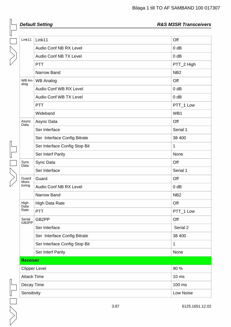
Default Setting R&S M3SR Transceivers
Bilaga 1 till TO AF SAMBAND 100 017307
Link11 Link11 Off
Audio Conf NB RX Level 0 dB
Audio Conf NB TX Level 0 dB
PTT PTT_2 High
Narrow Band NB2
WB An-alog
WB Analog Off
Audio Conf WB RX Level 0 dB
Audio Conf WB TX Level 0 dB
PTT PTT_1 Low
Wideband WB1
Async Data
Async Data Off
Ser Interface Serial 1
Ser Interface Config Bitrate 38 400
Ser Interface Config Stop Bit 1
Ser Interf Parity None
Sync Data
Sync Data Off
Ser Interface Serial 1
Guard Moni-toring
Guard Off
Audio Conf NB RX Level 0 dB
Narrow Band NB2
High Data Rate
High Data Rate Off
PTT PTT_1 Low
Serial GB2PP
GB2PP Off
Ser Interface Serial 2
Ser Interface Config Bitrate 38 400
Ser Interface Config Stop Bit 1
Ser Interf Parity None
Receiver
Clipper Level 90 %
Attack Time 10 ms
Decay Time 100 ms
Sensitivity Low Noise
3.87 6125.1651.12.02
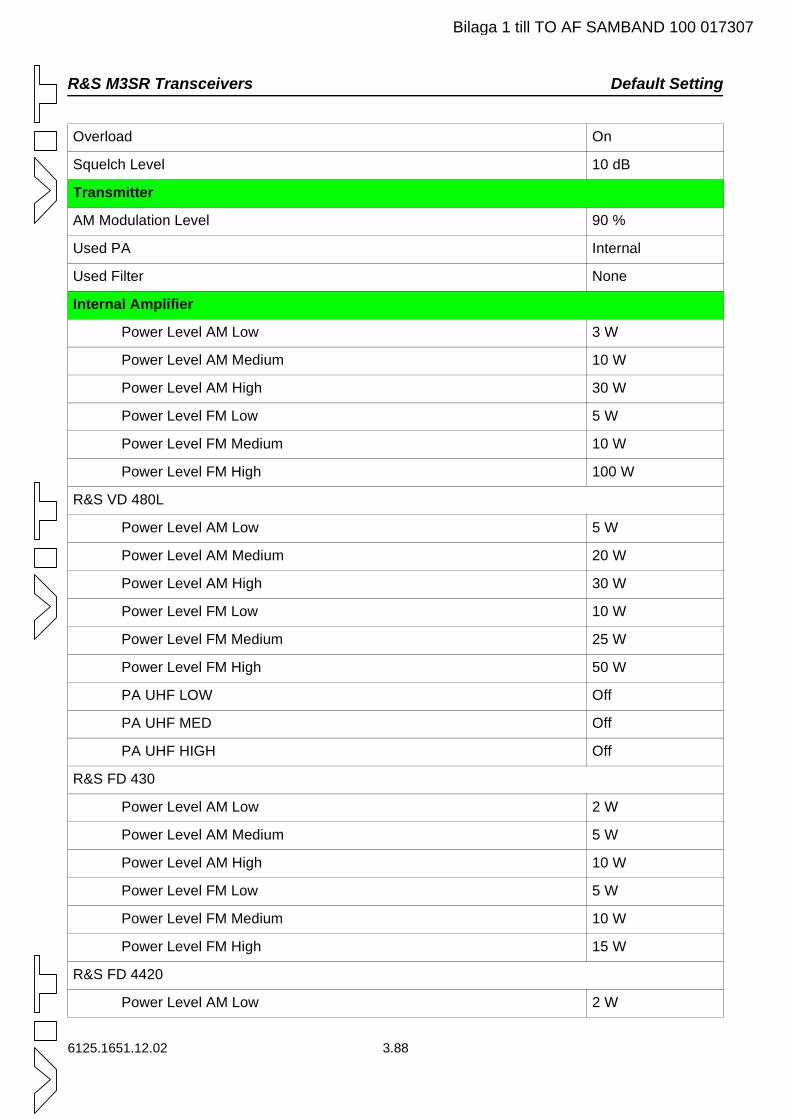
R&S M3SR Transceivers Default Setting
Bilaga 1 till TO AF SAMBAND 100 017307
Overload On
Squelch Level 10 dB
Transmitter
AM Modulation Level 90 %
Used PA Internal
Used Filter None
Internal Amplifier
Power Level AM Low 3 W
Power Level AM Medium 10 W
Power Level AM High 30 W
Power Level FM Low 5 W
Power Level FM Medium 10 W
Power Level FM High 100 W
R&S VD 480L
Power Level AM Low 5 W
Power Level AM Medium 20 W
Power Level AM High 30 W
Power Level FM Low 10 W
Power Level FM Medium 25 W
Power Level FM High 50 W
PA UHF LOW Off
PA UHF MED Off
PA UHF HIGH Off
R&S FD 430
Power Level AM Low 2 W
Power Level AM Medium 5 W
Power Level AM High 10 W
Power Level FM Low 5 W
Power Level FM Medium 10 W
Power Level FM High 15 W
R&S FD 4420
Power Level AM Low 2 W
6125.1651.12.02 3.88
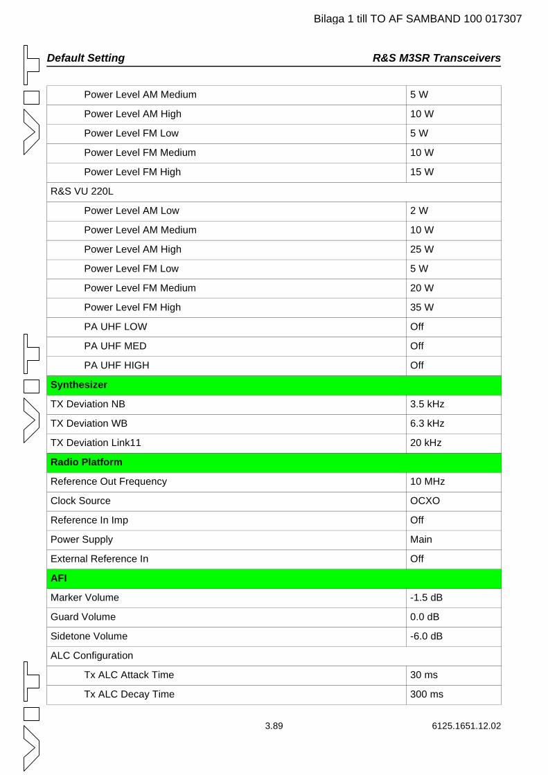
Default Setting R&S M3SR Transceivers
Bilaga 1 till TO AF SAMBAND 100 017307
Power Level AM Medium 5 W
Power Level AM High 10 W
Power Level FM Low 5 W
Power Level FM Medium 10 W
Power Level FM High 15 W
R&S VU 220L
Power Level AM Low 2 W
Power Level AM Medium 10 W
Power Level AM High 25 W
Power Level FM Low 5 W
Power Level FM Medium 20 W
Power Level FM High 35 W
PA UHF LOW Off
PA UHF MED Off
PA UHF HIGH Off
Synthesizer
TX Deviation NB 3.5 kHz
TX Deviation WB 6.3 kHz
TX Deviation Link11 20 kHz
Radio Platform
Reference Out Frequency 10 MHz
Clock Source OCXO
Reference In Imp Off
Power Supply Main
External Reference In Off
AFI
Marker Volume -1.5 dB
Guard Volume 0.0 dB
Sidetone Volume -6.0 dB
ALC Configuration
Tx ALC Attack Time 30 ms
Tx ALC Decay Time 300 ms
3.89 6125.1651.12.02
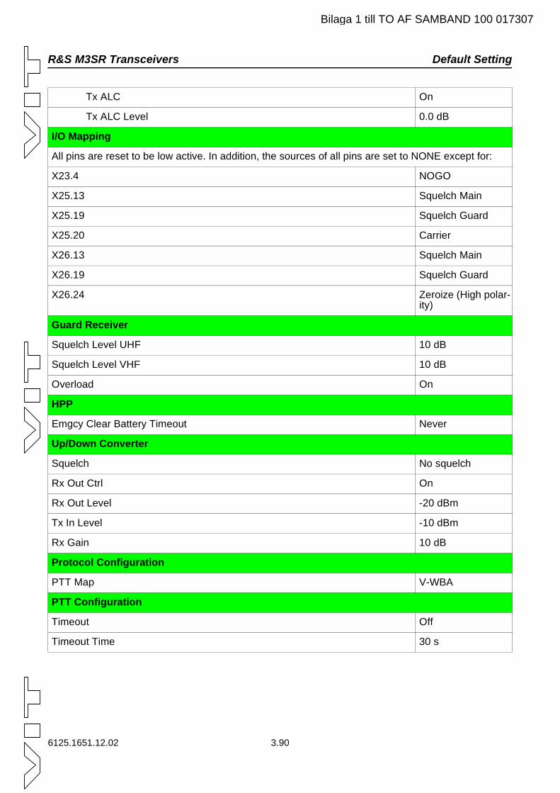
R&S M3SR Transceivers Default Setting
Bilaga 1 till TO AF SAMBAND 100 017307
Tx ALC On
Tx ALC Level 0.0 dB
I/O Mapping
All pins are reset to be low active. In addition, the sources of all pins are set to NONE except for:
X23.4 NOGO
X25.13 Squelch Main
X25.19 Squelch Guard
X25.20 Carrier
X26.13 Squelch Main
X26.19 Squelch Guard
X26.24 Zeroize (High polar-ity)
Guard Receiver
Squelch Level UHF 10 dB
Squelch Level VHF 10 dB
Overload On
HPP
Emgcy Clear Battery Timeout Never
Up/Down Converter
Squelch No squelch
Rx Out Ctrl On
Rx Out Level -20 dBm
Tx In Level -10 dBm
Rx Gain 10 dB
Protocol Configuration
PTT Map V-WBA
PTT Configuration
Timeout Off
Timeout Time 30 s
6125.1651.12.02 3.90
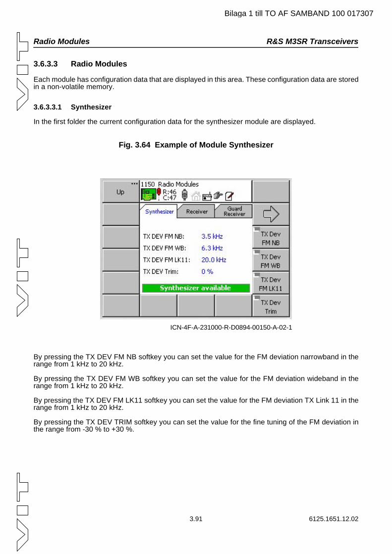
Radio Modules R&S M3SR Transceivers
Bilaga 1 till TO AF SAMBAND 100 017307
3.6.3.3 Radio Modules
Each module has configuration data that are displayed in this area. These configuration data are stored in a non-volatile memory.
3.6.3.3.1 Synthesizer
In the first folder the current configuration data for the synthesizer module are displayed.
Fig. 3.64 Example of Module Synthesizer
By pressing the TX DEV FM NB softkey you can set the value for the FM deviation narrowband in the range from 1 kHz to 20 kHz.
By pressing the TX DEV FM WB softkey you can set the value for the FM deviation wideband in the range from 1 kHz to 20 kHz.
By pressing the TX DEV FM LK11 softkey you can set the value for the FM deviation TX Link 11 in the range from 1 kHz to 20 kHz.
By pressing the TX DEV TRIM softkey you can set the value for the fine tuning of the FM deviation in the range from -30 % to +30 %.
ICN-4F-A-231000-R-D0894-00150-A-02-1
3.91 6125.1651.12.02
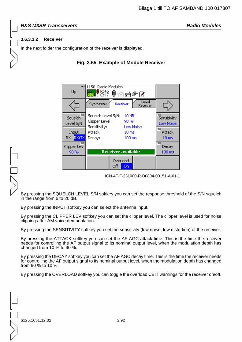
R&S M3SR Transceivers Radio Modules
Bilaga 1 till TO AF SAMBAND 100 017307
3.6.3.3.2 Receiver
In the next folder the configuration of the receiver is displayed.
Fig. 3.65 Example of Module Receiver
By pressing the SQUELCH LEVEL S/N softkey you can set the response threshold of the S/N squelch in the range from 6 to 20 dB.
By pressing the INPUT softkey you can select the antenna input.
By pressing the CLIPPER LEV softkey you can set the clipper level. The clipper level is used for noise clipping after AM voice demodulation.
By pressing the SENSITIVITY softkey you set the sensitivity (low noise, low distortion) of the receiver.
By pressing the ATTACK softkey you can set the AF AGC attack time. This is the time the receiver needs for controlling the AF output signal to its nominal output level, when the modulation depth has changed from 10 % to 90 %.
By pressing the DECAY softkey you can set the AF AGC decay time. This is the time the receiver needs for controlling the AF output signal to its nominal output level, when the modulation depth has changed from 90 % to 10 %.
By pressing the OVERLOAD softkey you can toggle the overload CBIT warnings for the receiver on/off.
ICN-4F-F-231000-R-D0894-00151-A-01-1
6125.1651.12.02 3.92
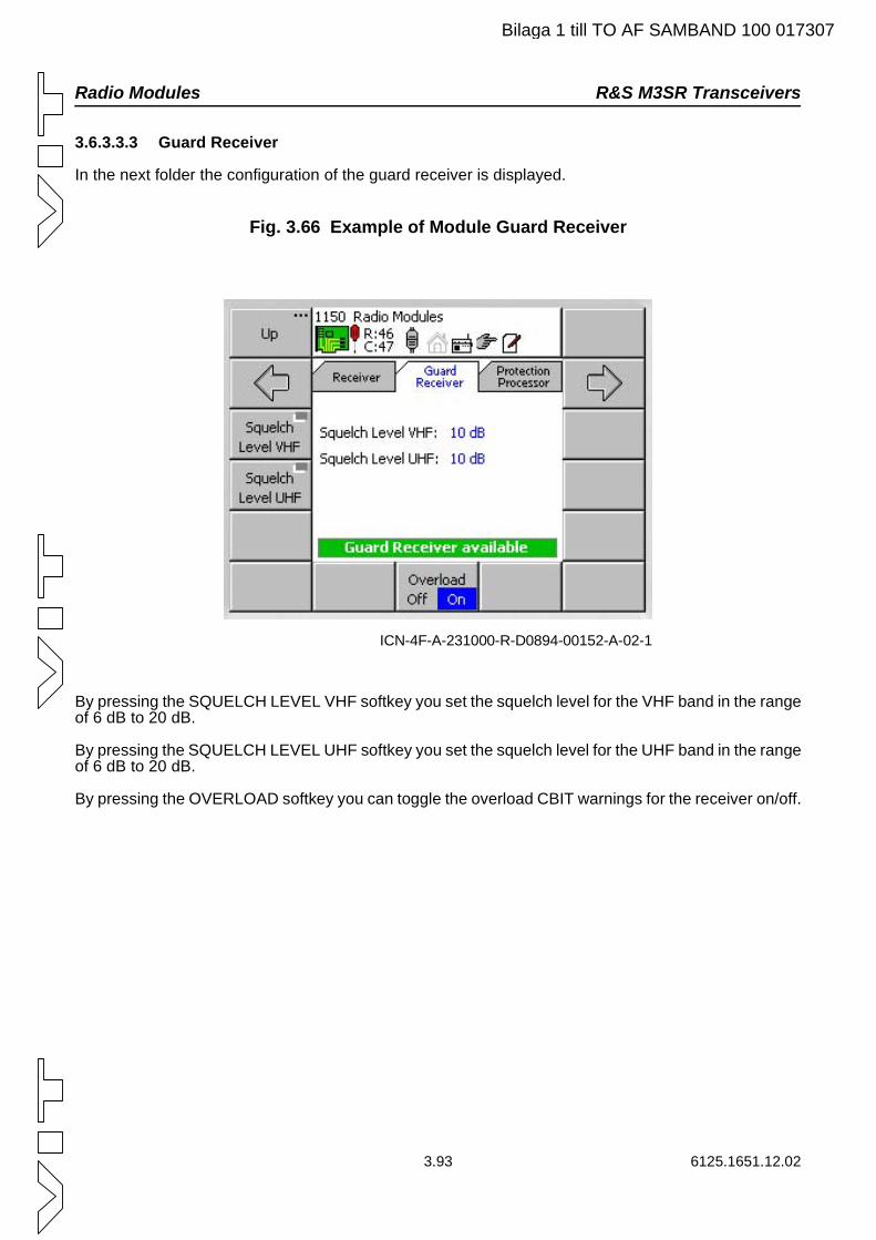
Radio Modules R&S M3SR Transceivers
Bilaga 1 till TO AF SAMBAND 100 017307
3.6.3.3.3 Guard Receiver
In the next folder the configuration of the guard receiver is displayed.
Fig. 3.66 Example of Module Guard Receiver
By pressing the SQUELCH LEVEL VHF softkey you set the squelch level for the VHF band in the range of 6 dB to 20 dB.
By pressing the SQUELCH LEVEL UHF softkey you set the squelch level for the UHF band in the range of 6 dB to 20 dB.
By pressing the OVERLOAD softkey you can toggle the overload CBIT warnings for the receiver on/off.
ICN-4F-A-231000-R-D0894-00152-A-02-1
3.93 6125.1651.12.02
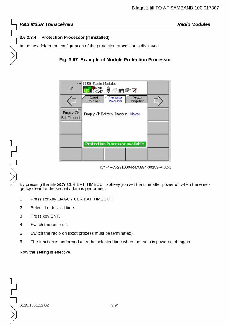
R&S M3SR Transceivers Radio Modules
Bilaga 1 till TO AF SAMBAND 100 017307
3.6.3.3.4 Protection Processor (if installed)
In the next folder the configuration of the protection processor is displayed.
Fig. 3.67 Example of Module Protection Processor
By pressing the EMGCY CLR BAT TIMEOUT softkey you set the time after power off when the emer-gency clear for the security data is performed.
1 Press softkey EMGCY CLR BAT TIMEOUT.
2 Select the desired time.
3 Press key ENT.
4 Switch the radio off.
5 Switch the radio on (boot process must be terminated).
6 The function is performed after the selected time when the radio is powered off again.
Now the setting is effective.
ICN-4F-A-231000-R-D0894-00153-A-02-1
6125.1651.12.02 3.94
Radio Modules R&S M3SR Transceivers
Bilaga 1 till TO AF SAMBAND 100 017307
3.6.3.3.5 Power Amplifier
3.6.3.3.5.1 Configuration of Power Amplifier
C A U T I O N
If the following instructions are disregarded or a power amplifier / filter different from the selected one is connected, the power amplifier / filter can be seriously damaged.
1 If required, switch the radio off.
2 If required, disconnect the external power amplifier / filter.
3 If required, the switch radio on.
4 Press the USED PA softkey (see Fig. 3.68) to select the desired power amplifier / filter.
5 Press the PA CONFIG softkey (see Fig. 3.69) to configure the power levels for the selected pow-er amplifier / filter.
6 If required, switch the radio off.
7 If required, connect the selected power amplifier / filter.
In the next folder the configuration of the power amplifier is displayed.
3.95 6125.1651.12.02
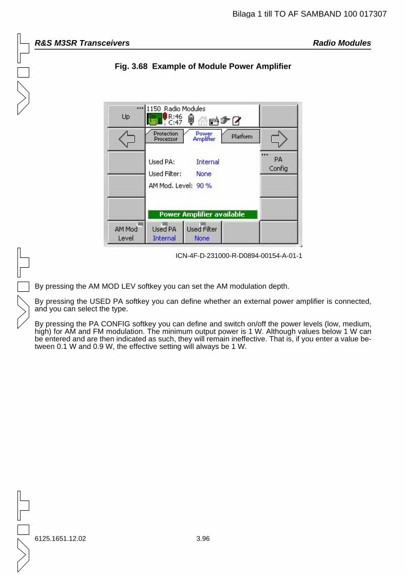
R&S M3SR Transceivers Radio Modules
Bilaga 1 till TO AF SAMBAND 100 017307
Fig. 3.68 Example of Module Power Amplifier
By pressing the AM MOD LEV softkey you can set the AM modulation depth.
By pressing the USED PA softkey you can define whether an external power amplifier is connected, and you can select the type.
By pressing the PA CONFIG softkey you can define and switch on/off the power levels (low, medium, high) for AM and FM modulation. The minimum output power is 1 W. Although values below 1 W can be entered and are then indicated as such, they will remain ineffective. That is, if you enter a value be-tween 0.1 W and 0.9 W, the effective setting will always be 1 W.
ICN-4F-D-231000-R-D0894-00154-A-01-1
6125.1651.12.02 3.96
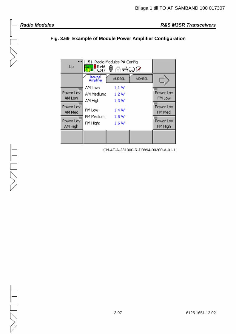
Radio Modules R&S M3SR Transceivers
Bilaga 1 till TO AF SAMBAND 100 017307
Fig. 3.69 Example of Module Power Amplifier Configuration
ICN-4F-A-231000-R-D0894-00200-A-01-1
3.97 6125.1651.12.02
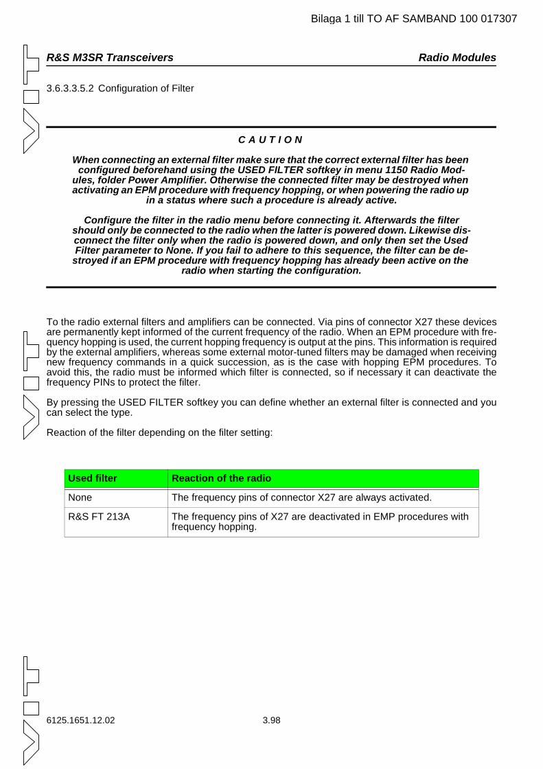
R&S M3SR Transceivers Radio Modules
Bilaga 1 till TO AF SAMBAND 100 017307
3.6.3.3.5.2 Configuration of Filter
C A U T I O N
When connecting an external filter make sure that the correct external filter has been configured beforehand using the USED FILTER softkey in menu 1150 Radio Mod-
ules, folder Power Amplifier. Otherwise the connected filter may be destroyed when activating an EPM procedure with frequency hopping, or when powering the radio up
in a status where such a procedure is already active.
Configure the filter in the radio menu before connecting it. Afterwards the filter should only be connected to the radio when the latter is powered down. Likewise dis-connect the filter only when the radio is powered down, and only then set the Used Filter parameter to None. If you fail to adhere to this sequence, the filter can be de-
stroyed if an EPM procedure with frequency hopping has already been active on the radio when starting the configuration.
To the radio external filters and amplifiers can be connected. Via pins of connector X27 these devices are permanently kept informed of the current frequency of the radio. When an EPM procedure with fre-quency hopping is used, the current hopping frequency is output at the pins. This information is required by the external amplifiers, whereas some external motor-tuned filters may be damaged when receiving new frequency commands in a quick succession, as is the case with hopping EPM procedures. To avoid this, the radio must be informed which filter is connected, so if necessary it can deactivate the frequency PINs to protect the filter.
By pressing the USED FILTER softkey you can define whether an external filter is connected and you can select the type.
Reaction of the filter depending on the filter setting:
Used filter Reaction of the radio
None The frequency pins of connector X27 are always activated.
R&S FT 213A The frequency pins of X27 are deactivated in EMP procedures with frequency hopping.
6125.1651.12.02 3.98
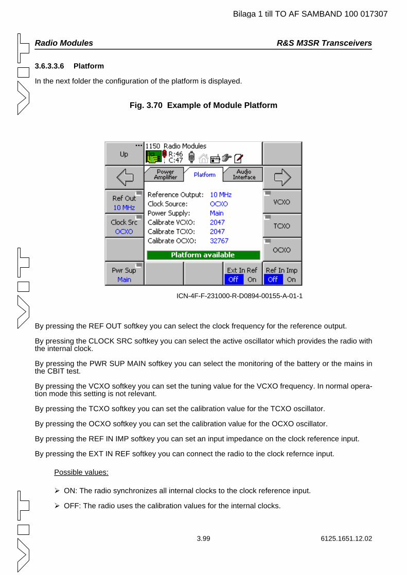
Radio Modules R&S M3SR Transceivers
Bilaga 1 till TO AF SAMBAND 100 017307
3.6.3.3.6 Platform
In the next folder the configuration of the platform is displayed.
Fig. 3.70 Example of Module Platform
By pressing the REF OUT softkey you can select the clock frequency for the reference output.
By pressing the CLOCK SRC softkey you can select the active oscillator which provides the radio with the internal clock.
By pressing the PWR SUP MAIN softkey you can select the monitoring of the battery or the mains in the CBIT test.
By pressing the VCXO softkey you can set the tuning value for the VCXO frequency. In normal opera-tion mode this setting is not relevant.
By pressing the TCXO softkey you can set the calibration value for the TCXO oscillator.
By pressing the OCXO softkey you can set the calibration value for the OCXO oscillator.
By pressing the REF IN IMP softkey you can set an input impedance on the clock reference input.
By pressing the EXT IN REF softkey you can connect the radio to the clock refernce input.
Possible values:
ON: The radio synchronizes all internal clocks to the clock reference input.
OFF: The radio uses the calibration values for the internal clocks.
ICN-4F-F-231000-R-D0894-00155-A-01-1
3.99 6125.1651.12.02
R&S M3SR Transceivers Radio Modules
Bilaga 1 till TO AF SAMBAND 100 017307
3.6.3.3.7 Audio Interface
In the next folder the configuration of the audio interface is displayed.
Fig. 3.71 Example of Module Audio Interface
By pressing the MARKER VOLUME softkey you can set the volume of the marker signal.
By pressing the GUARD VOLUME softkey you can set the volume of the guard signal.
By pressing the SIDETONE VOLUME softkey you can set the volume of the narrowband sidetone.
By pressing the ALC CONFIG softkey you can set the values for the automatic level control.
By pressing the CODEC CALIBRATION softkey you can set the values for the audio lines (NB1, NB2, WB1, WB2).
C A U T I O N
Codec calibration values are radio-specific. Do not change these values!
Exception: After changing the battery on the platform the codecs need to be calibrated. For instructions see service documentation.
ICN-4F-A-231000-R-D0894-00156-A-02-1
6125.1651.12.02 3.100
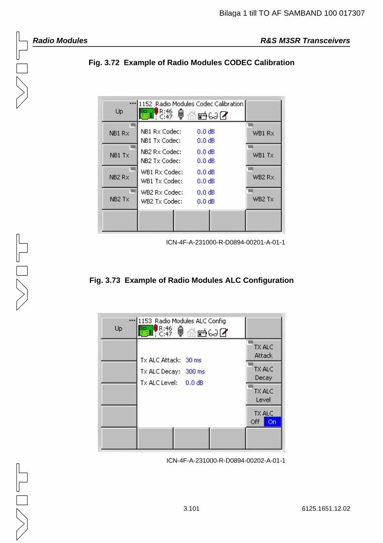
Radio Modules R&S M3SR Transceivers
Bilaga 1 till TO AF SAMBAND 100 017307
Fig. 3.72 Example of Radio Modules CODEC Calibration
Fig. 3.73 Example of Radio Modules ALC Configuration
ICN-4F-A-231000-R-D0894-00201-A-01-1
ICN-4F-A-231000-R-D0894-00202-A-01-1
3.101 6125.1651.12.02
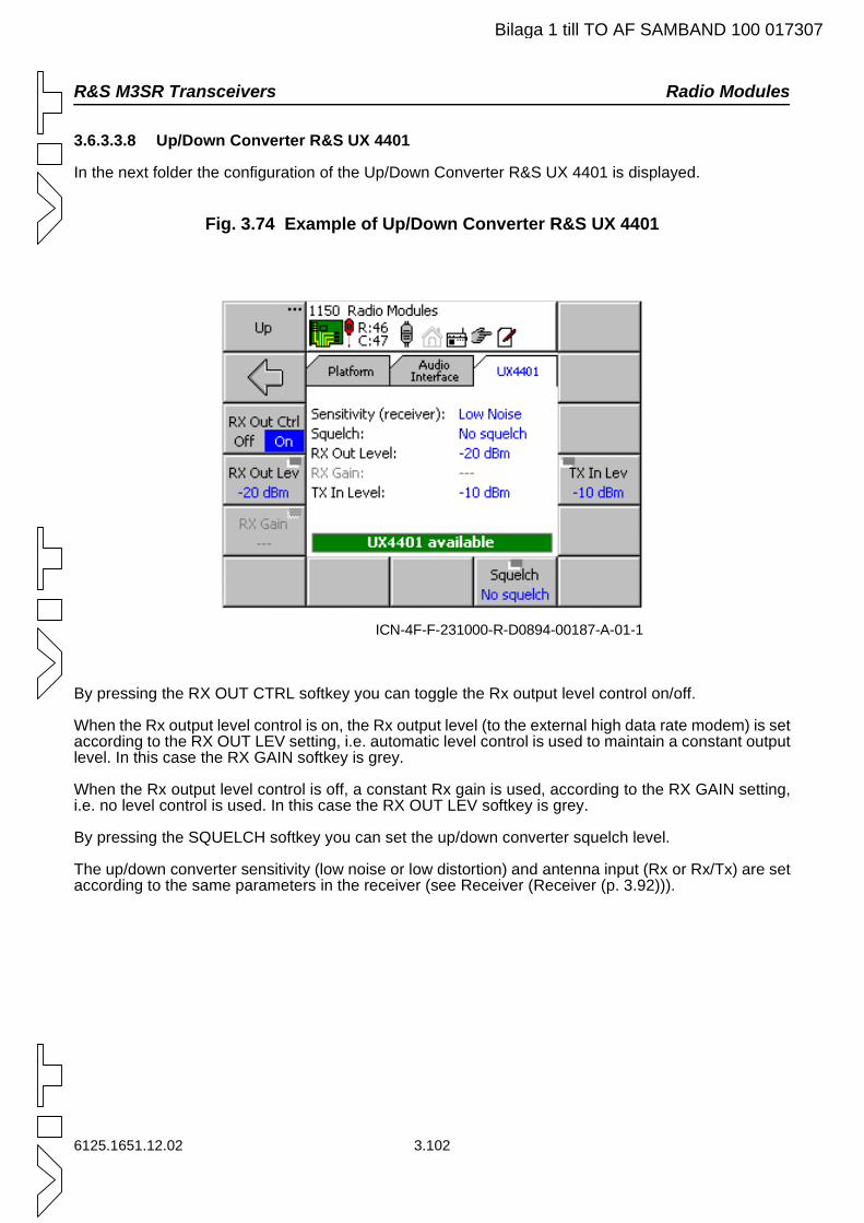
R&S M3SR Transceivers Radio Modules
Bilaga 1 till TO AF SAMBAND 100 017307
3.6.3.3.8 Up/Down Converter R&S UX 4401
In the next folder the configuration of the Up/Down Converter R&S UX 4401 is displayed.
Fig. 3.74 Example of Up/Down Converter R&S UX 4401
By pressing the RX OUT CTRL softkey you can toggle the Rx output level control on/off.
When the Rx output level control is on, the Rx output level (to the external high data rate modem) is set according to the RX OUT LEV setting, i.e. automatic level control is used to maintain a constant output level. In this case the RX GAIN softkey is grey.
When the Rx output level control is off, a constant Rx gain is used, according to the RX GAIN setting, i.e. no level control is used. In this case the RX OUT LEV softkey is grey.
By pressing the SQUELCH softkey you can set the up/down converter squelch level.
The up/down converter sensitivity (low noise or low distortion) and antenna input (Rx or Rx/Tx) are set according to the same parameters in the receiver (see Receiver (Receiver (p. 3.92))).
ICN-4F-F-231000-R-D0894-00187-A-01-1
6125.1651.12.02 3.102
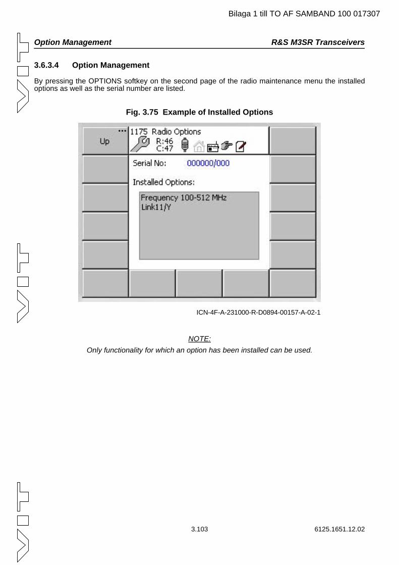
Option Management R&S M3SR Transceivers
Bilaga 1 till TO AF SAMBAND 100 017307
3.6.3.4 Option Management
By pressing the OPTIONS softkey on the second page of the radio maintenance menu the installed options as well as the serial number are listed.
Fig. 3.75 Example of Installed Options
NOTE:Only functionality for which an option has been installed can be used.
ICN-4F-A-231000-R-D0894-00157-A-02-1
3.103 6125.1651.12.02
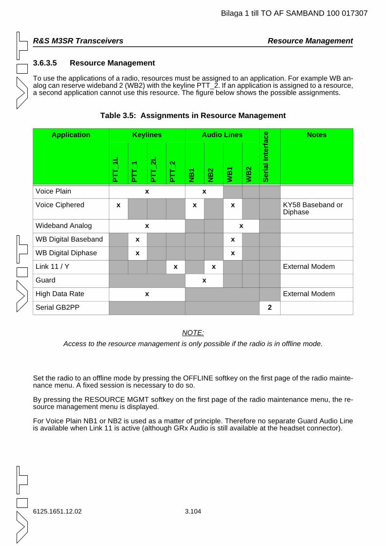
R&S M3SR Transceivers Resource Management
Bilaga 1 till TO AF SAMBAND 100 017307
3.6.3.5 Resource Management
To use the applications of a radio, resources must be assigned to an application. For example WB an-alog can reserve wideband 2 (WB2) with the keyline PTT_2. If an application is assigned to a resource, a second application cannot use this resource. The figure below shows the possible assignments.
Table 3.5: Assignments in Resource Management
NOTE:Access to the resource management is only possible if the radio is in offline mode.
Set the radio to an offline mode by pressing the OFFLINE softkey on the first page of the radio mainte-nance menu. A fixed session is necessary to do so.
By pressing the RESOURCE MGMT softkey on the first page of the radio maintenance menu, the re-source management menu is displayed.
For Voice Plain NB1 or NB2 is used as a matter of principle. Therefore no separate Guard Audio Line is available when Link 11 is active (although GRx Audio is still available at the headset connector).
Application Keylines Audio Lines
Seria
lInt
erfa
ce Notes
PTT_
1L
PTT_
1
PTT_
2L
PTT_
2
NB
1
NB
2
WB
1
WB
2
Voice Plain x x
Voice Ciphered x x x KY58 Baseband or Diphase
Wideband Analog x x
WB Digital Baseband x x
WB Digital Diphase x x
Link 11 / Y x x External Modem
Guard x
High Data Rate x External Modem
Serial GB2PP 2
6125.1651.12.02 3.104
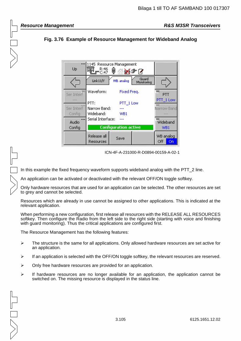
Resource Management R&S M3SR Transceivers
Bilaga 1 till TO AF SAMBAND 100 017307
Fig. 3.76 Example of Resource Management for Wideband Analog
In this example the fixed frequency waveform supports wideband analog with the PTT_2 line.
An application can be activated or deactivated with the relevant OFF/ON toggle softkey.
Only hardware resources that are used for an application can be selected. The other resources are set to grey and cannot be selected.
Resources which are already in use cannot be assigned to other applications. This is indicated at the relevant application.
When performing a new configuration, first release all resources with the RELEASE ALL RESOURCES softkey. Then configure the Radio from the left side to the right side (starting with voice and finishing with guard monitoring). Thus the critical applications are configured first.
The Resource Management has the following features:
The structure is the same for all applications. Only allowed hardware resources are set active for an application.
If an application is selected with the OFF/ON toggle softkey, the relevant resources are reserved.
Only free hardware resources are provided for an application.
If hardware resources are no longer available for an application, the application cannot be switched on. The missing resource is displayed in the status line.
ICN-4F-A-231000-R-D0894-00159-A-02-1
3.105 6125.1651.12.02
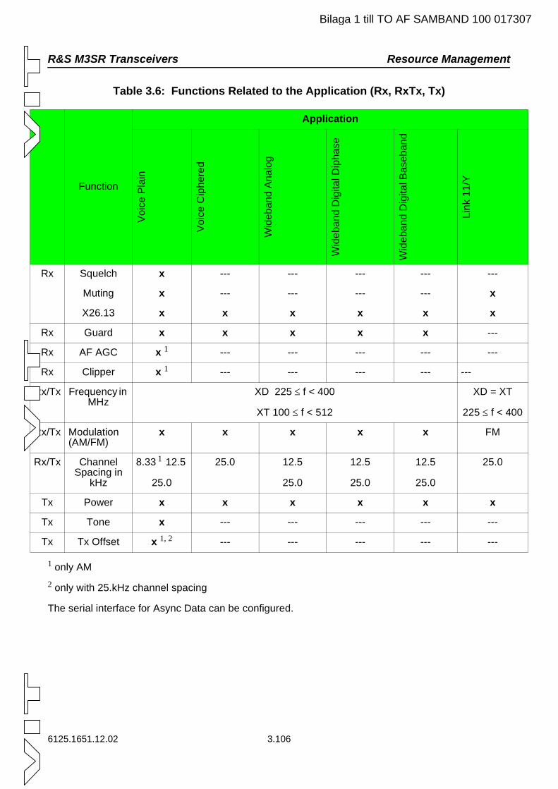
R&S M3SR Transceivers Resource Management
R
R
R
Bilaga 1 till TO AF SAMBAND 100 017307
Table 3.6: Functions Related to the Application (Rx, RxTx, Tx)
1 only AM2 only with 25.kHz channel spacing
The serial interface for Async Data can be configured.
Function
Application
Voi
ceP
lain
Voi
ceC
iphe
red
Wid
eban
dA
nalo
g
Wid
eban
dD
igita
lDip
hase
Wid
eban
dD
igita
lBas
eban
d
Link
11/Y
Rx Squelch x --- --- --- --- ---
Muting x --- --- --- --- x
X26.13 x x x x x x
Rx Guard x x x x x ---
Rx AF AGC x 1 --- --- --- --- ---
Rx Clipper x 1 --- --- --- --- ---
x/Tx Frequency in MHz
XD 225 ≤ f < 400
XT 100 ≤ f < 512
XD = XT
225 ≤ f < 400
x/Tx Modulation (AM/FM)
x x x x x FM
x/Tx Channel Spacing in
kHz
8.33 1 12.5
25.0
25.0 12.5
25.0
12.5
25.0
12.5
25.0
25.0
Tx Power x x x x x x
Tx Tone x --- --- --- --- ---
Tx Tx Offset x 1, 2 --- --- --- --- ---
6125.1651.12.02 3.106
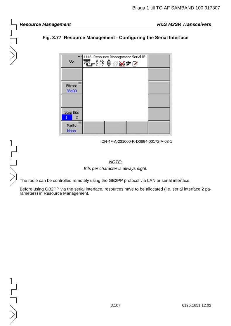
Resource Management R&S M3SR Transceivers
Bilaga 1 till TO AF SAMBAND 100 017307
Fig. 3.77 Resource Management - Configuring the Serial Interface
NOTE:Bits per character is always eight.
The radio can be controlled remotely using the GB2PP protocol via LAN or serial interface.
Before using GB2PP via the serial interface, resources have to be allocated (i.e. serial interface 2 pa-rameters) in Resource Management.
ICN-4F-A-231000-R-D0894-00172-A-03-1
3.107 6125.1651.12.02
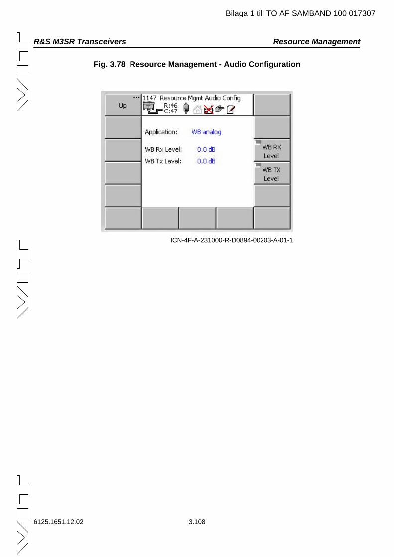
R&S M3SR Transceivers Resource Management
Bilaga 1 till TO AF SAMBAND 100 017307
Fig. 3.78 Resource Management - Audio Configuration
ICN-4F-A-231000-R-D0894-00203-A-01-1
6125.1651.12.02 3.108
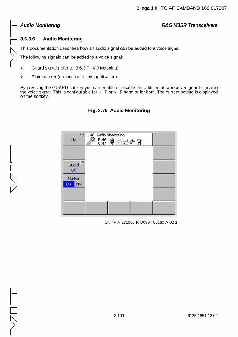
Audio Monitoring R&S M3SR Transceivers
3.109 6125.1651.12.02
3.6.3.6 Audio Monitoring
This documentation describes how an audio signal can be added to a voice signal.
The following signals can be added to a voice signal:
Guard signal (refer to 3.6.3.7 - I/O Mapping)
Plain marker (no function in this application)
By pressing the GUARD softkey you can enable or disable the addition of a received guard signal to the voice signal. This is configurable for UHF or VHF band or for both. The current setting is displayed on the softkey.
Fig. 3.79 Audio Monitoring
ICN-4F-A-231000-R-D0894-00160-A-02-1
Bilaga 1 till TO AF SAMBAND 100 017307
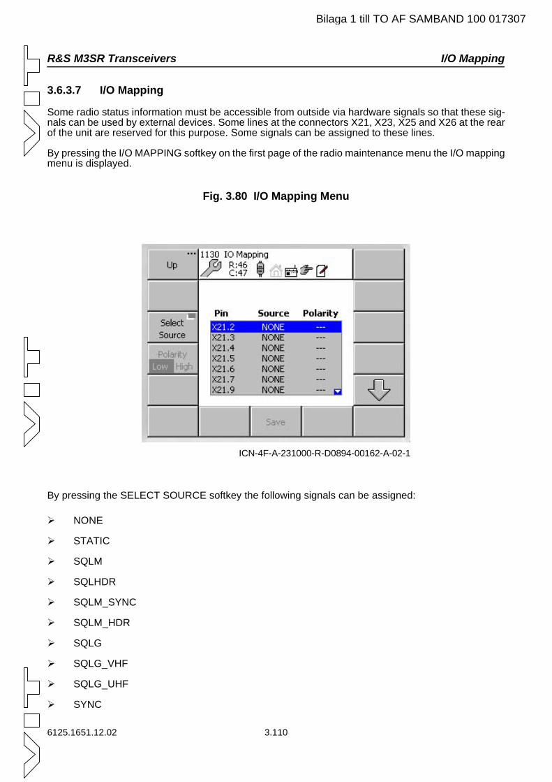
R&S M3SR Transceivers I/O Mapping
Bilaga 1 till TO AF SAMBAND 100 017307
3.6.3.7 I/O Mapping
Some radio status information must be accessible from outside via hardware signals so that these sig-nals can be used by external devices. Some lines at the connectors X21, X23, X25 and X26 at the rear of the unit are reserved for this purpose. Some signals can be assigned to these lines.
By pressing the I/O MAPPING softkey on the first page of the radio maintenance menu the I/O mapping menu is displayed.
Fig. 3.80 I/O Mapping Menu
By pressing the SELECT SOURCE softkey the following signals can be assigned:
NONE
STATIC
SQLM
SQLHDR
SQLM_SYNC
SQLM_HDR
SQLG
SQLG_VHF
SQLG_UHF
SYNC
ICN-4F-A-231000-R-D0894-00162-A-02-1
6125.1651.12.02 3.110
I/O Mapping R&S M3SR Transceivers
Bilaga 1 till TO AF SAMBAND 100 017307
ZEROIZE
CARR
NOGO
DPP_CONFIG
MODE_HDR
COMSEC
TRANSEC
COM_TRANSEC
After a signal has been assigned to a connector line, the polarity can be changed with the POLARITY softkey.
3.111 6125.1651.12.02
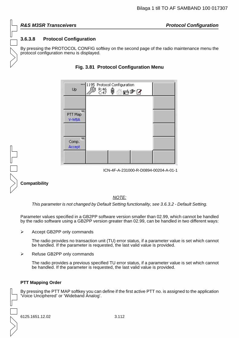
R&S M3SR Transceivers Protocol Configuration
6125.1651.12.02 3.112
3.6.3.8 Protocol Configuration
By pressing the PROTOCOL CONFIG softkey on the second page of the radio maintenance menu the protocol configuration menu is displayed.
Fig. 3.81 Protocol Configuration Menu
Compatibility
NOTE:This parameter is not changed by Default Setting functionality, see 3.6.3.2 - Default Setting.
Parameter values specified in a GB2PP software version smaller than 02.99, which cannot be handled by the radio software using a GB2PP version greater than 02.99, can be handled in two different ways:
Accept GB2PP only commands
The radio provides no transaction unit (TU) error status, if a parameter value is set which cannot be handled. If the parameter is requested, the last valid value is provided.
Refuse GB2PP only commands
The radio provides a previous specified TU error status, if a parameter value is set which cannot be handled. If the parameter is requested, the last valid value is provided.
PTT Mapping Order
By pressing the PTT MAP softkey you can define if the first active PTT no. is assigned to the application ’Voice Unciphered’ or ’Wideband Analog’.
ICN-4F-A-231000-R-D0894-00204-A-01-1
Bilaga 1 till TO AF SAMBAND 100 017307
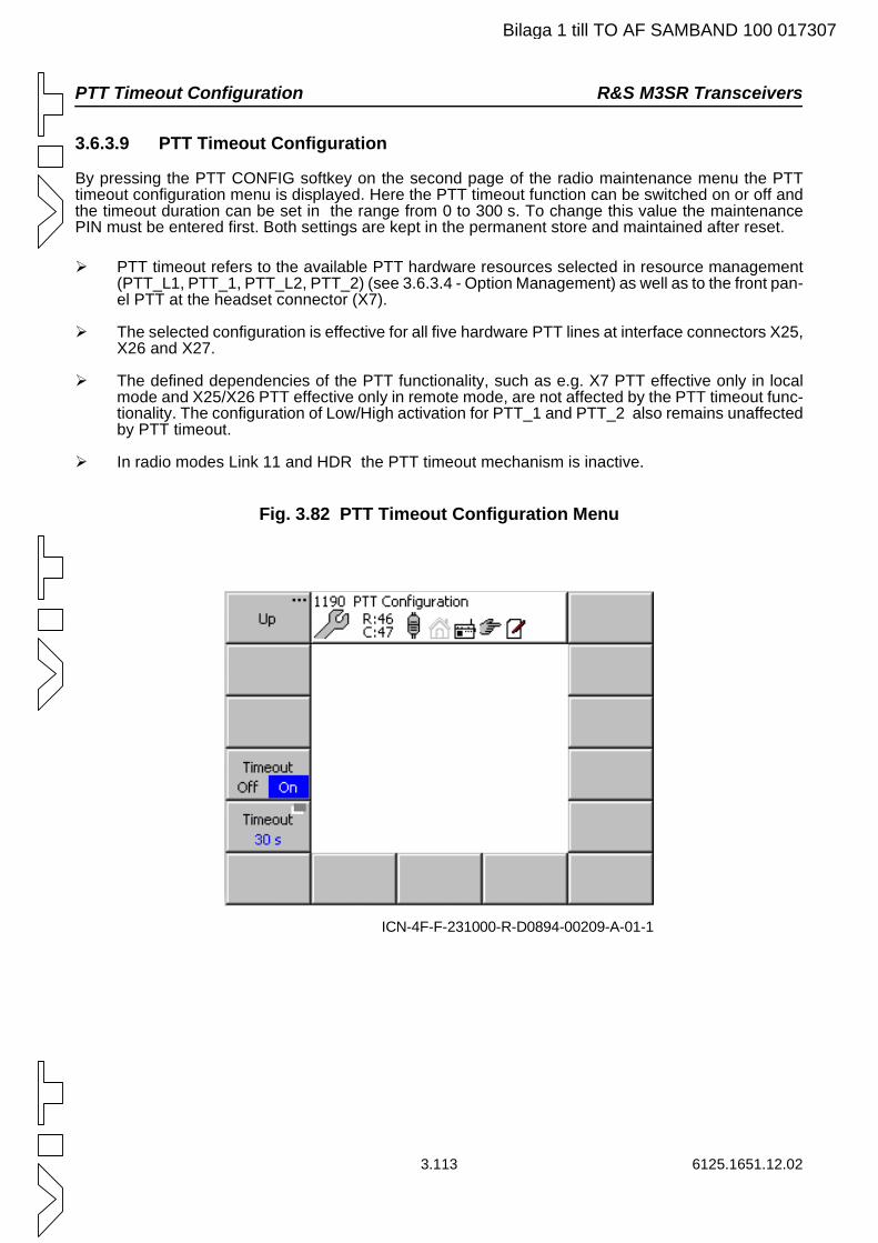
PTT Timeout Configuration R&S M3SR Transceivers
Bilaga 1 till TO AF SAMBAND 100 017307
3.6.3.9 PTT Timeout Configuration
By pressing the PTT CONFIG softkey on the second page of the radio maintenance menu the PTT timeout configuration menu is displayed. Here the PTT timeout function can be switched on or off and the timeout duration can be set in the range from 0 to 300 s. To change this value the maintenance PIN must be entered first. Both settings are kept in the permanent store and maintained after reset.
PTT timeout refers to the available PTT hardware resources selected in resource management (PTT_L1, PTT_1, PTT_L2, PTT_2) (see 3.6.3.4 - Option Management) as well as to the front pan-el PTT at the headset connector (X7).
The selected configuration is effective for all five hardware PTT lines at interface connectors X25, X26 and X27.
The defined dependencies of the PTT functionality, such as e.g. X7 PTT effective only in local mode and X25/X26 PTT effective only in remote mode, are not affected by the PTT timeout func-tionality. The configuration of Low/High activation for PTT_1 and PTT_2 also remains unaffected by PTT timeout.
In radio modes Link 11 and HDR the PTT timeout mechanism is inactive.
Fig. 3.82 PTT Timeout Configuration Menu
ICN-4F-F-231000-R-D0894-00209-A-01-1
3.113 6125.1651.12.02
R&S M3SR Transceivers PTT Timeout Configuration
Bilaga 1 till TO AF SAMBAND 100 017307
PTT Timeout OffThe five PTT hardware lines are treated as before. Continuous transmission via PTT is possible. PTT-related functions such as TX Inhibit are still possible.
PTT Timeout OnWhen the PTT hardware line for the currently active radio mode is activated, a timer is started which ensures that the radio stops transmitting once the configured timeout has elapsed. When this PTT hardware line is retriggered, the radio returns to transmit mode and the timer is reset.Activating another PTT hardware line, which is not configured for the currently active radio mode, has no effect on the PTT timeout functionality.In parallel to the PTT timeout, an active TX Inhibit ensures that the radio stops transmitting. When TX Inhibit is then deactivated, the currently used PTT hardware line is handled as if retriggered.Changing the mode while PTT is set has the same effect as retriggering PTT, where the timer is started anew.
CBIT Message for PTT Timeout
The moment the timer monitoring the PTT hardware lines runs into the configured timeout, a CBIT message is created. It is displayed in the MMI, signalled via GB2PP and recorded in the error log.
Reconfiguration while PTT is activeIf the radio is reconfigured while PTT is active, the currently used PTT hardware line is handled as if retriggered, i.e. the timer is started anew with the new values.
6125.1651.12.02 3.114
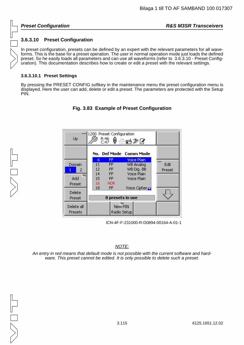
Preset Configuration R&S M3SR Transceivers
Bilaga 1 till TO AF SAMBAND 100 017307
3.6.3.10 Preset Configuration
In preset configuration, presets can be defined by an expert with the relevant parameters for all wave-forms. This is the base for a preset operation. The user in normal operation mode just loads the defined preset. So he easily loads all parameters and can use all waveforms (refer to 3.6.3.10 - Preset Config-uration). This documentation describes how to create or edit a preset with the relevant settings.
3.6.3.10.1 Preset Settings
By pressing the PRESET CONFIG softkey in the maintenance menu the preset configuration menu is displayed. Here the user can add, delete or edit a preset. The parameters are protected with the Setup PIN.
Fig. 3.83 Example of Preset Configuration
NOTE:An entry in red means that default mode is not possible with the current software and hard-
ware. This preset cannot be edited. It is only possible to delete such a preset.
ICN-4F-F-231000-R-D0894-00164-A-01-1
3.115 6125.1651.12.02
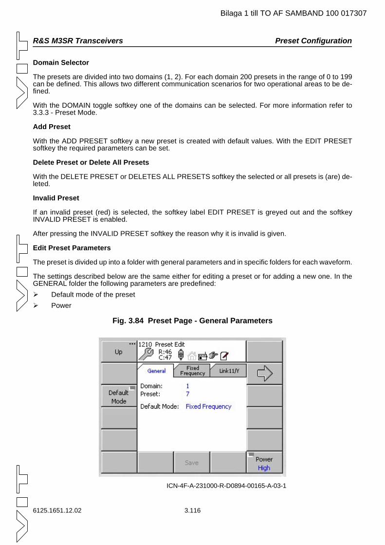
R&S M3SR Transceivers Preset Configuration
Bilaga 1 till TO AF SAMBAND 100 017307
Domain Selector
The presets are divided into two domains (1, 2). For each domain 200 presets in the range of 0 to 199 can be defined. This allows two different communication scenarios for two operational areas to be de-fined.
With the DOMAIN toggle softkey one of the domains can be selected. For more information refer to 3.3.3 - Preset Mode.
Add Preset
With the ADD PRESET softkey a new preset is created with default values. With the EDIT PRESET softkey the required parameters can be set.
Delete Preset or Delete All Presets
With the DELETE PRESET or DELETES ALL PRESETS softkey the selected or all presets is (are) de-leted.
Invalid Preset
If an invalid preset (red) is selected, the softkey label EDIT PRESET is greyed out and the softkey INVALID PRESET is enabled.
After pressing the INVALID PRESET softkey the reason why it is invalid is given.
Edit Preset Parameters
The preset is divided up into a folder with general parameters and in specific folders for each waveform.
The settings described below are the same either for editing a preset or for adding a new one. In the GENERAL folder the following parameters are predefined: Default mode of the preset Power
Fig. 3.84 Preset Page - General Parameters
ICN-4F-A-231000-R-D0894-00165-A-03-1
6125.1651.12.02 3.116
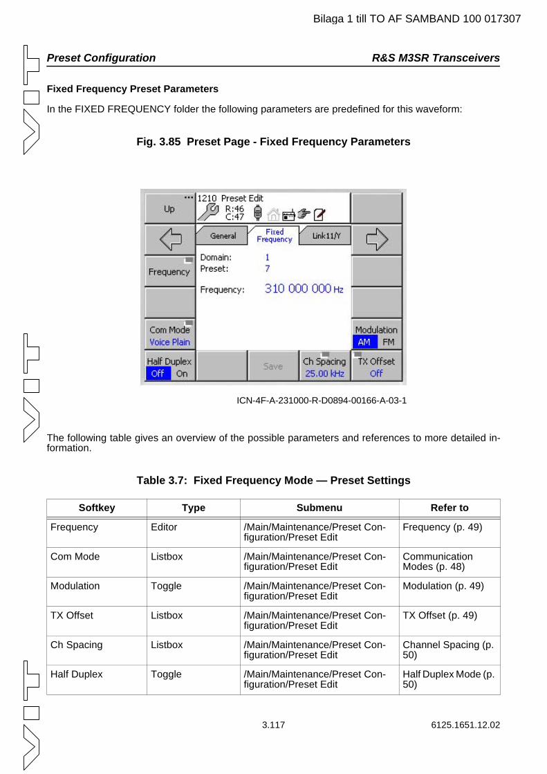
Preset Configuration R&S M3SR Transceivers
Bilaga 1 till TO AF SAMBAND 100 017307
Fixed Frequency Preset Parameters
In the FIXED FREQUENCY folder the following parameters are predefined for this waveform:
Fig. 3.85 Preset Page - Fixed Frequency Parameters
The following table gives an overview of the possible parameters and references to more detailed in-formation.
Table 3.7: Fixed Frequency Mode — Preset Settings
Softkey Type Submenu Refer to
Frequency Editor /Main/Maintenance/Preset Con-figuration/Preset Edit
Frequency (p. 49)
Com Mode Listbox /Main/Maintenance/Preset Con-figuration/Preset Edit
Communication Modes (p. 48)
Modulation Toggle /Main/Maintenance/Preset Con-figuration/Preset Edit
Modulation (p. 49)
TX Offset Listbox /Main/Maintenance/Preset Con-figuration/Preset Edit
TX Offset (p. 49)
Ch Spacing Listbox /Main/Maintenance/Preset Con-figuration/Preset Edit
Channel Spacing (p. 50)
Half Duplex Toggle /Main/Maintenance/Preset Con-figuration/Preset Edit
Half Duplex Mode (p. 50)
ICN-4F-A-231000-R-D0894-00166-A-03-1
3.117 6125.1651.12.02
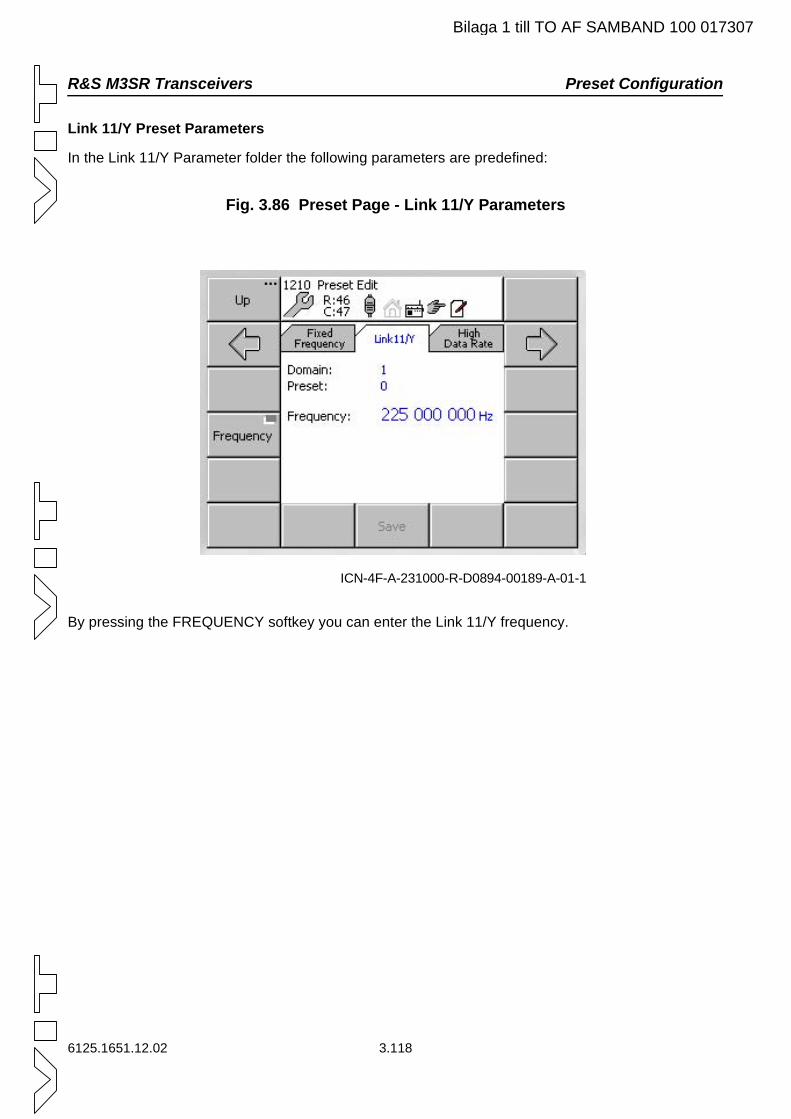
R&S M3SR Transceivers Preset Configuration
Bilaga 1 till TO AF SAMBAND 100 017307
Link 11/Y Preset Parameters
In the Link 11/Y Parameter folder the following parameters are predefined:
Fig. 3.86 Preset Page - Link 11/Y Parameters
By pressing the FREQUENCY softkey you can enter the Link 11/Y frequency.
ICN-4F-A-231000-R-D0894-00189-A-01-1
6125.1651.12.02 3.118
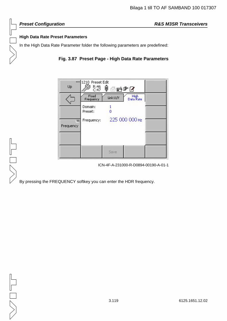
Preset Configuration R&S M3SR Transceivers
Bilaga 1 till TO AF SAMBAND 100 017307
High Data Rate Preset Parameters
In the High Data Rate Parameter folder the following parameters are predefined:
Fig. 3.87 Preset Page - High Data Rate Parameters
By pressing the FREQUENCY softkey you can enter the HDR frequency.
ICN-4F-A-231000-R-D0894-00190-A-01-1
3.119 6125.1651.12.02
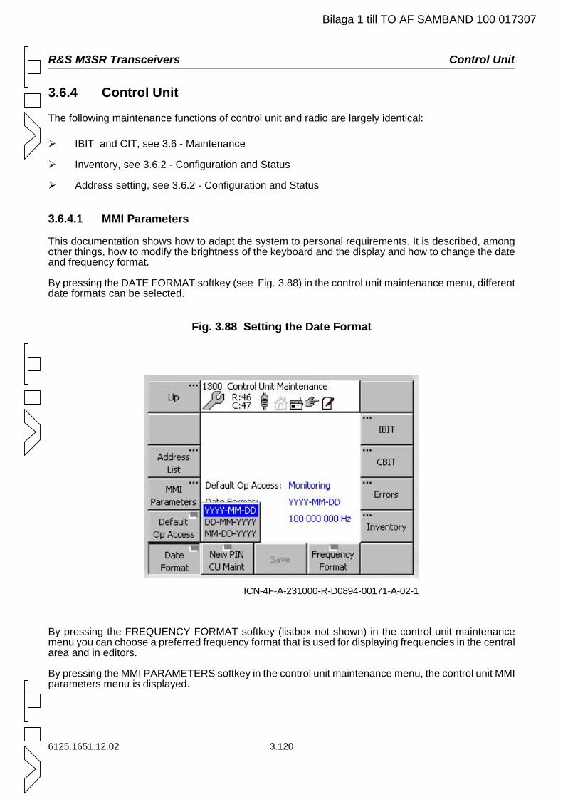
R&S M3SR Transceivers Control Unit
Bilaga 1 till TO AF SAMBAND 100 017307
3.6.4 Control Unit
The following maintenance functions of control unit and radio are largely identical:
IBIT and CIT, see 3.6 - Maintenance
Inventory, see 3.6.2 - Configuration and Status
Address setting, see 3.6.2 - Configuration and Status
3.6.4.1 MMI Parameters
This documentation shows how to adapt the system to personal requirements. It is described, among other things, how to modify the brightness of the keyboard and the display and how to change the date and frequency format.
By pressing the DATE FORMAT softkey (see Fig. 3.88) in the control unit maintenance menu, different date formats can be selected.
Fig. 3.88 Setting the Date Format
By pressing the FREQUENCY FORMAT softkey (listbox not shown) in the control unit maintenance menu you can choose a preferred frequency format that is used for displaying frequencies in the central area and in editors.
By pressing the MMI PARAMETERS softkey in the control unit maintenance menu, the control unit MMI parameters menu is displayed.
ICN-4F-A-231000-R-D0894-00171-A-02-1
6125.1651.12.02 3.120
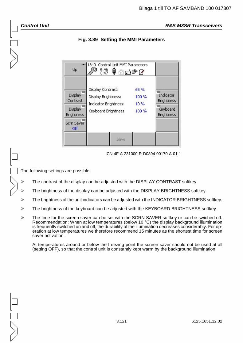
Control Unit R&S M3SR Transceivers
Bilaga 1 till TO AF SAMBAND 100 017307
Fig. 3.89 Setting the MMI Parameters
The following settings are possible:
The contrast of the display can be adjusted with the DISPLAY CONTRAST softkey.
The brightness of the display can be adjusted with the DISPLAY BRIGHTNESS softkey.
The brightness of the unit indicators can be adjusted with the INDICATOR BRIGHTNESS softkey.
The brightness of the keyboard can be adjusted with the KEYBOARD BRIGHTNESS softkey.
The time for the screen saver can be set with the SCRN SAVER softkey or can be swiched off. Recommendation: When at low temperatures (below 10 °C) the display background illumination is frequently switched on and off, the durability of the illumination decreases considerably. For op-eration at low temperatures we therefore recommend 15 minutes as the shortest time for screen saver activation.
At temperatures around or below the freezing point the screen saver should not be used at all (setting OFF), so that the control unit is constantly kept warm by the background illumination.
ICN-4F-A-231000-R-D0894-00170-A-01-1
3.121 6125.1651.12.02
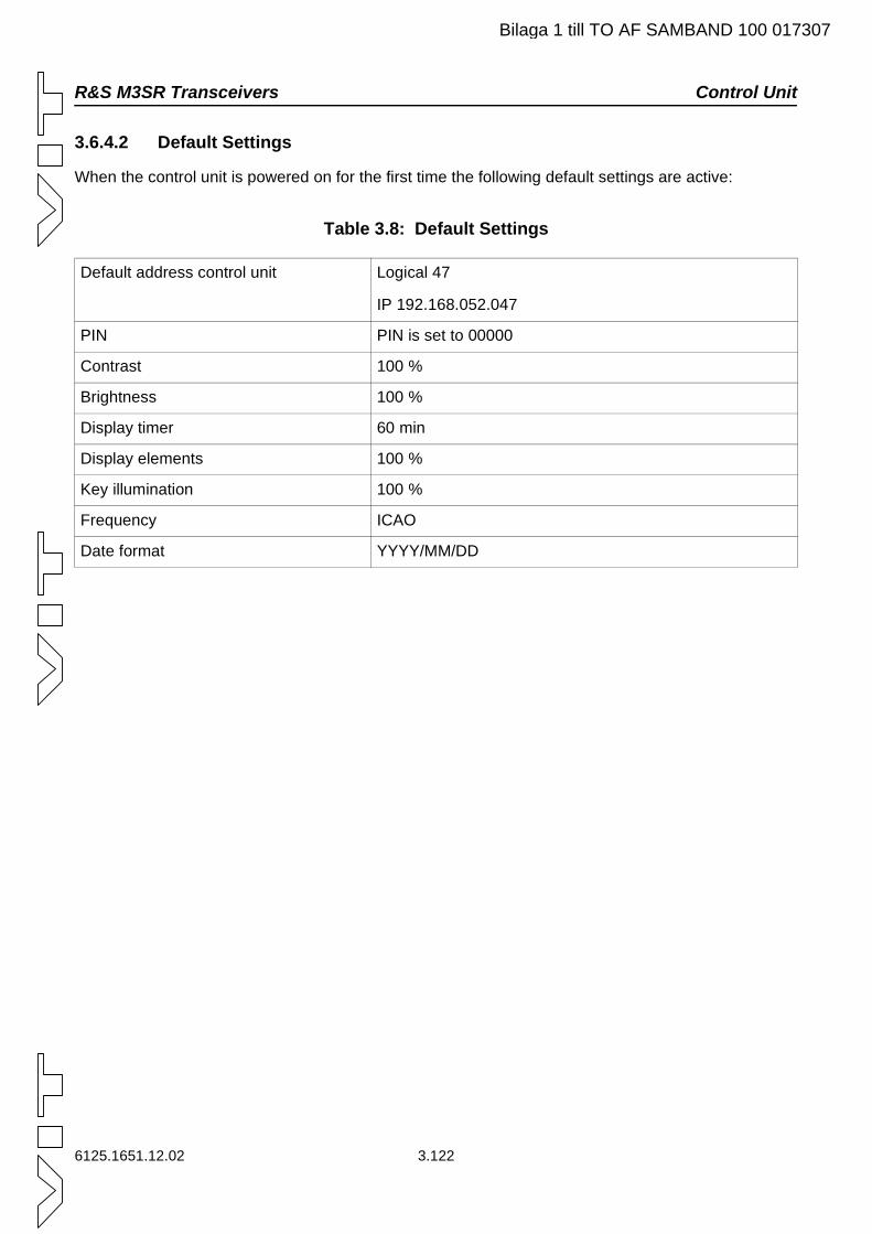
R&S M3SR Transceivers Control Unit
Bilaga 1 till TO AF SAMBAND 100 017307
3.6.4.2 Default Settings
When the control unit is powered on for the first time the following default settings are active:
Table 3.8: Default Settings
Default address control unit Logical 47
IP 192.168.052.047
PIN PIN is set to 00000
Contrast 100 %
Brightness 100 %
Display timer 60 min
Display elements 100 %
Key illumination 100 %
Frequency ICAO
Date format YYYY/MM/DD
6125.1651.12.02 3.122
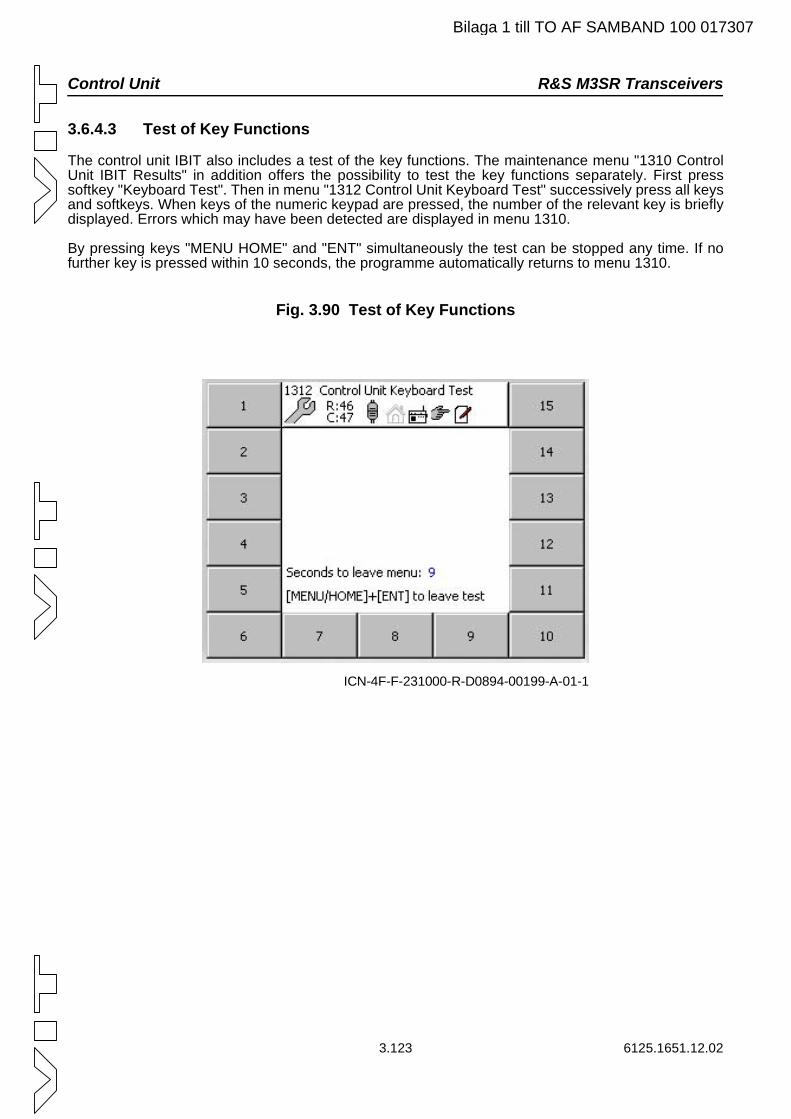
Control Unit R&S M3SR Transceivers
Bilaga 1 till TO AF SAMBAND 100 017307
3.6.4.3 Test of Key Functions
The control unit IBIT also includes a test of the key functions. The maintenance menu "1310 Control Unit IBIT Results" in addition offers the possibility to test the key functions separately. First press softkey "Keyboard Test". Then in menu "1312 Control Unit Keyboard Test" successively press all keys and softkeys. When keys of the numeric keypad are pressed, the number of the relevant key is briefly displayed. Errors which may have been detected are displayed in menu 1310.
By pressing keys "MENU HOME" and "ENT" simultaneously the test can be stopped any time. If no further key is pressed within 10 seconds, the programme automatically returns to menu 1310.
Fig. 3.90 Test of Key Functions
ICN-4F-F-231000-R-D0894-00199-A-01-1
3.123 6125.1651.12.02

R&S M3SR Transceivers Control Unit
Bilaga 1 till TO AF SAMBAND 100 017307
6125.1651.12.02 3.124
Malfunctions R&S M3SR Transceivers
4.1 6125.1651.12.02
4. Malfunctions
4.1 Visual Inspection
C A U T I O N
If a connector shows any discoloration caused by heat, its mating connector is also defective and must also be replaced.
Check the following:
1 Check the external wiring between the radio with or without the control unit and the external equipment.
2 Check if all connectors are plugged in firmly.
3 Check the power supply cable and the RF coaxial cables at the rear for mechanical damage.
If necessary, replace cables by new ones one by one until the defective connection has been found.
Obvious damage of minor importance can be corrected at once, assuming that the appropriate equip-ment is available. In case of severe damage, the transceiver must be sent to the nearest repair facility.
Bilaga 1 till TO AF SAMBAND 100 017307
R&S M3SR Transceivers Malfunctions
6125.1651.12.02 4.2
Bilaga 1 till TO AF SAMBAND 100 017307
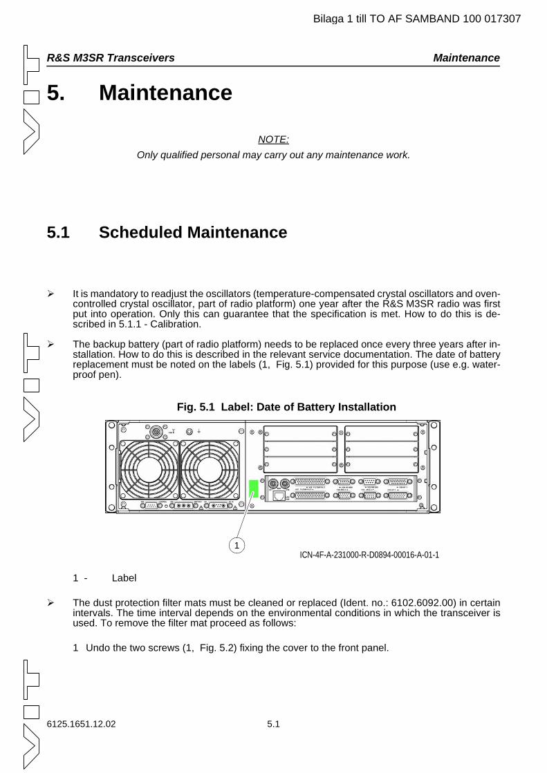
R&S M3SR Transceivers Maintenance
Bilaga 1 till TO AF SAMBAND 100 017307
5. Maintenance
NOTE:Only qualified personal may carry out any maintenance work.
5.1 Scheduled Maintenance
It is mandatory to readjust the oscillators (temperature-compensated crystal oscillators and oven-controlled crystal oscillator, part of radio platform) one year after the R&S M3SR radio was first put into operation. Only this can guarantee that the specification is met. How to do this is de-scribed in 5.1.1 - Calibration.
The backup battery (part of radio platform) needs to be replaced once every three years after in-stallation. How to do this is described in the relevant service documentation. The date of battery replacement must be noted on the labels (1, Fig. 5.1) provided for this purpose (use e.g. water-proof pen).
Fig. 5.1 Label: Date of Battery Installation
1 - Label
The dust protection filter mats must be cleaned or replaced (Ident. no.: 6102.6092.00) in certain intervals. The time interval depends on the environmental conditions in which the transceiver is used. To remove the filter mat proceed as follows:
1 Undo the two screws (1, Fig. 5.2) fixing the cover to the front panel.
ICN-4F-A-231000-R-D0894-00016-A-01-11
6125.1651.12.02 5.1
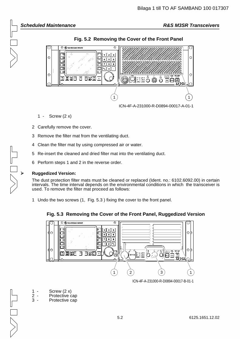
Scheduled Maintenance R&S M3SR Transceivers
Bilaga 1 till TO AF SAMBAND 100 017307
Fig. 5.2 Removing the Cover of the Front Panel
1 - Screw (2 x)
2 Carefully remove the cover.
3 Remove the filter mat from the ventilating duct.
4 Clean the filter mat by using compressed air or water.
5 Re-insert the cleaned and dried filter mat into the ventilating duct.
6 Perform steps 1 and 2 in the reverse order.
Ruggedized Version:The dust protection filter mats must be cleaned or replaced (Ident. no.: 6102.6092.00) in certain intervals. The time interval depends on the environmental conditions in which the transceiver is used. To remove the filter mat proceed as follows:
1 Undo the two screws (1, Fig. 5.3 ) fixing the cover to the front panel.
Fig. 5.3 Removing the Cover of the Front Panel, Ruggedized Version
1 - Screw (2 x)2 - Protective cap3 - Protective cap
ICN-4F-A-231000-R-D0894-00017-A-01-1
1 1
3 1
ICN-4F-A-231000-R-D0894-00017-B-01-1
1 2
5.2 6125.1651.12.02
R&S M3SR Transceivers Scheduled Maintenance
Bilaga 1 till TO AF SAMBAND 100 017307
2 Remove the protective caps of the connectors (2 and 3).
3 Carefully remove the cover.
4 Remove the filter mat from the ventilating duct.
5 Clean the filter mat by using compressed air or water.
6 Re-insert the cleaned and dried filter mat into the ventilating duct.
7 Perform steps a and b in the reverse order.
Otherwise the transceiver is free from scheduled maintenance.
6125.1651.12.02 5.3
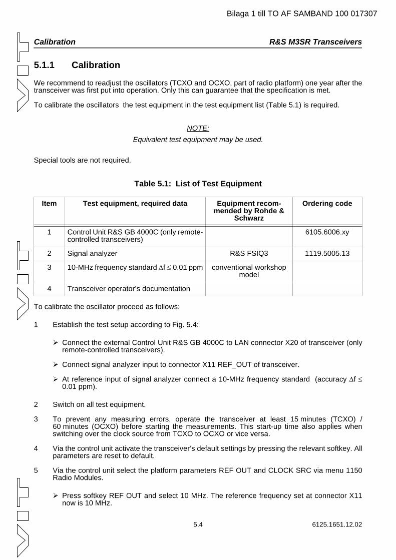
Calibration R&S M3SR Transceivers
Bilaga 1 till TO AF SAMBAND 100 017307
5.1.1 Calibration
We recommend to readjust the oscillators (TCXO and OCXO, part of radio platform) one year after the transceiver was first put into operation. Only this can guarantee that the specification is met.
To calibrate the oscillators the test equipment in the test equipment list (Table 5.1) is required.
NOTE:Equivalent test equipment may be used.
Special tools are not required.
Table 5.1: List of Test Equipment
To calibrate the oscillator proceed as follows:
1 Establish the test setup according to Fig. 5.4:
Connect the external Control Unit R&S GB 4000C to LAN connector X20 of transceiver (only remote-controlled transceivers).
Connect signal analyzer input to connector X11 REF_OUT of transceiver.
At reference input of signal analyzer connect a 10-MHz frequency standard (accuracy ∆f ≤0.01 ppm).
2 Switch on all test equipment.
3 To prevent any measuring errors, operate the transceiver at least 15 minutes (TCXO) / 60 minutes (OCXO) before starting the measurements. This start-up time also applies when switching over the clock source from TCXO to OCXO or vice versa.
4 Via the control unit activate the transceiver’s default settings by pressing the relevant softkey. All parameters are reset to default.
5 Via the control unit select the platform parameters REF OUT and CLOCK SRC via menu 1150 Radio Modules.
Press softkey REF OUT and select 10 MHz. The reference frequency set at connector X11 now is 10 MHz.
Item Test equipment, required data Equipment recom-mended by Rohde &
Schwarz
Ordering code
1 Control Unit R&S GB 4000C (only remote-controlled transceivers)
6105.6006.xy
2 Signal analyzer R&S FSIQ3 1119.5005.13
3 10-MHz frequency standard ∆f ≤ 0.01 ppm conventional workshop model
4 Transceiver operator’s documentation
5.4 6125.1651.12.02
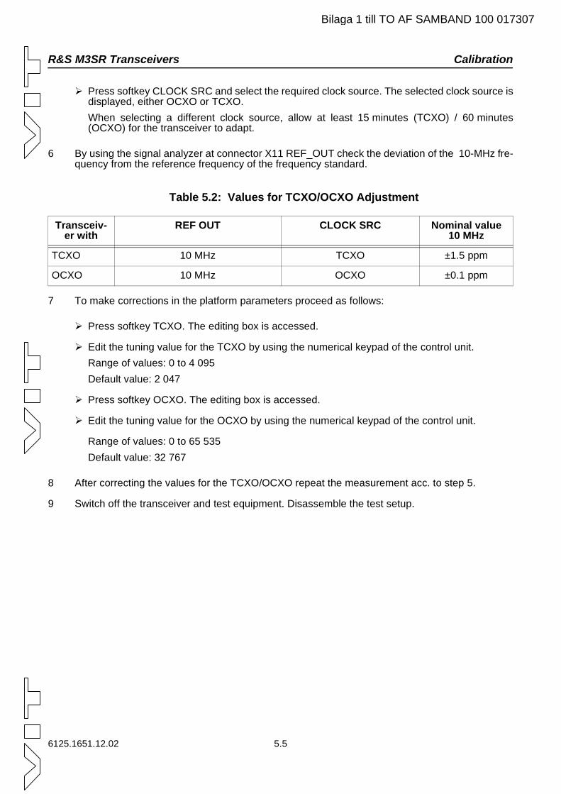
R&S M3SR Transceivers Calibration
Bilaga 1 till TO AF SAMBAND 100 017307
Press softkey CLOCK SRC and select the required clock source. The selected clock source is displayed, either OCXO or TCXO. When selecting a different clock source, allow at least 15 minutes (TCXO) / 60 minutes (OCXO) for the transceiver to adapt.
6 By using the signal analyzer at connector X11 REF_OUT check the deviation of the 10-MHz fre-quency from the reference frequency of the frequency standard.
Table 5.2: Values for TCXO/OCXO Adjustment
7 To make corrections in the platform parameters proceed as follows:
Press softkey TCXO. The editing box is accessed.
Edit the tuning value for the TCXO by using the numerical keypad of the control unit.Range of values: 0 to 4 095Default value: 2 047
Press softkey OCXO. The editing box is accessed.
Edit the tuning value for the OCXO by using the numerical keypad of the control unit.
Range of values: 0 to 65 535Default value: 32 767
8 After correcting the values for the TCXO/OCXO repeat the measurement acc. to step 5.
9 Switch off the transceiver and test equipment. Disassemble the test setup.
Transceiv-er with
REF OUT CLOCK SRC Nominal value 10 MHz
TCXO 10 MHz TCXO ±1.5 ppm
OCXO 10 MHz OCXO ±0.1 ppm
6125.1651.12.02 5.5
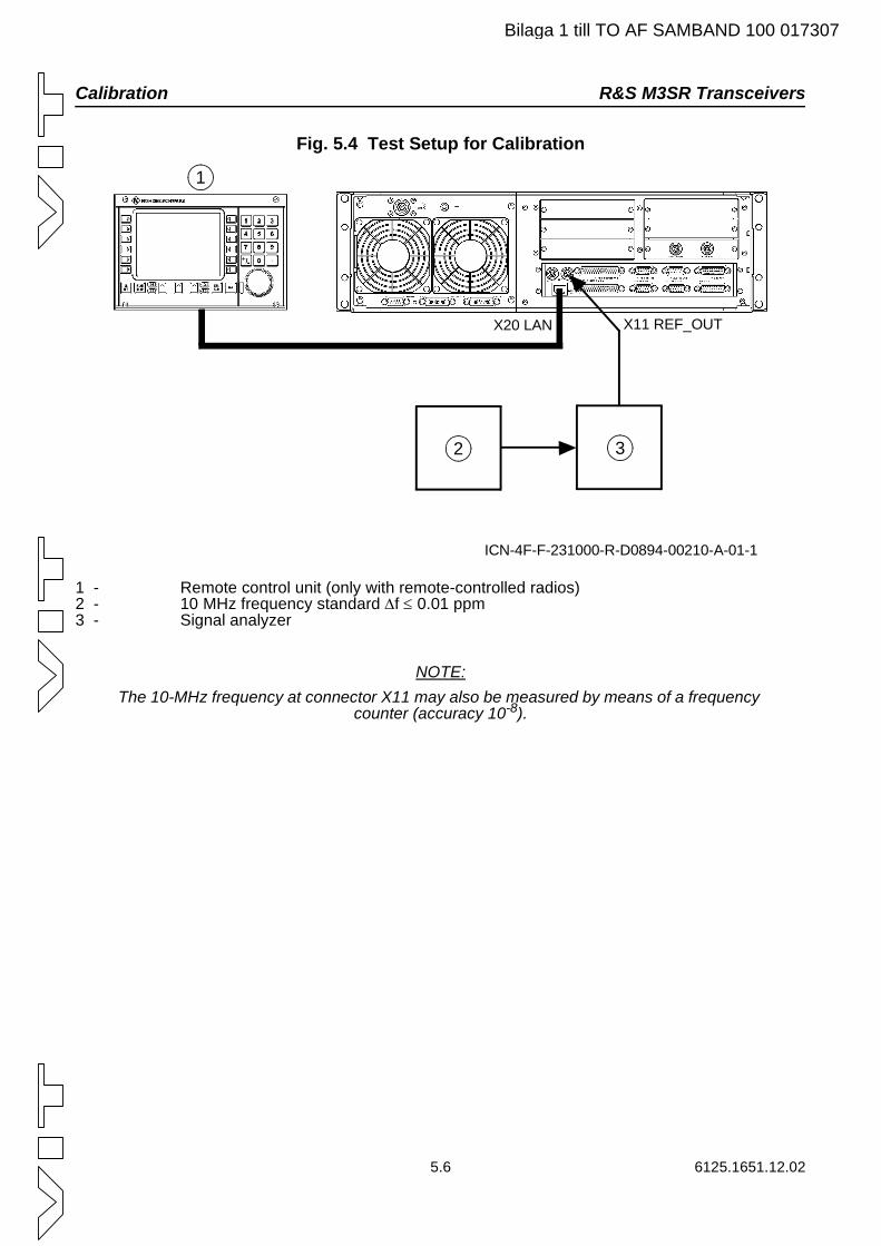
Calibration R&S M3SR Transceivers
Bilaga 1 till TO AF SAMBAND 100 017307
Fig. 5.4 Test Setup for Calibration
1 - Remote control unit (only with remote-controlled radios)2 - 10 MHz frequency standard ∆f ≤ 0.01 ppm3 - Signal analyzer
NOTE:The 10-MHz frequency at connector X11 may also be measured by means of a frequency
counter (accuracy 10-8).
ICN-4F-F-231000-R-D0894-00210-A-01-1
X20 LAN X11 REF_OUT
1
2 3
5.6 6125.1651.12.02
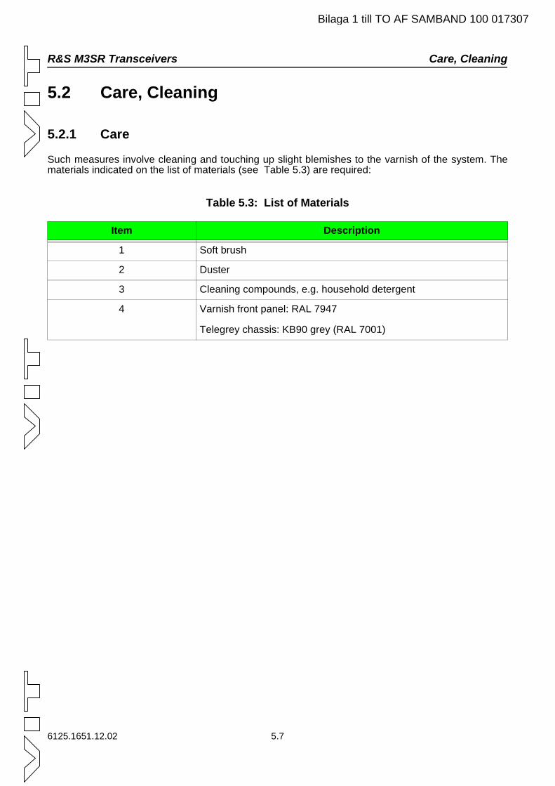
R&S M3SR Transceivers Care, Cleaning
Bilaga 1 till TO AF SAMBAND 100 017307
5.2 Care, Cleaning
5.2.1 Care
Such measures involve cleaning and touching up slight blemishes to the varnish of the system. The materials indicated on the list of materials (see Table 5.3) are required:
Table 5.3: List of Materials
Item Description
1 Soft brush
2 Duster
3 Cleaning compounds, e.g. household detergent
4 Varnish front panel: RAL 7947
Telegrey chassis: KB90 grey (RAL 7001)
6125.1651.12.02 5.7
Care, Cleaning R&S M3SR Transceivers
Bilaga 1 till TO AF SAMBAND 100 017307
5.2.2 Cleaning
W A R N I N G
Wear protective goggles to protect your eyes if you are working with com-pressed air.
C A U T I O N
Ensure that the compressed air is free of condensed water by first blowing the com-pressed air towards the ground.
Keep a minimum distance of 20 cm between compressed air and the system.
Do for cleaning not use solvents (thinners etc.), petroleum ether or alcohol.
Such substances will irreversibly damage the varnish coat.
1 First clean the surface of the system with compressed air.
2 Continue cleaning with a soft brush or a duster.
3 Clean heavily contaminated surfaces, especially grease stains, with a soft, lint-free cloth mois-tened with detergent.
5.8 6125.1651.12.02
R&S M3SR Transceivers Retouching the Paint Work
6125.1651.12.02 5.9
5.3 Retouching the Paint Work
Touch up the paint work of the unit as follows:
1 Remove any loose paint particles from the area of repair.
2 Clean the areas which have to be retouched with a soft, lint-free cloth and a cleaning detergent.
3 Wait until the unit is dry again.
4 Retouch the unit carefully and afterwards ensure that the paint has dried completely.
Bilaga 1 till TO AF SAMBAND 100 017307
Retouching the Paint Work R&S M3SR Transceivers
5.10 6125.1651.12.02
Bilaga 1 till TO AF SAMBAND 100 017307
Technical Information R&S M3SR Transceivers
A1.1 6125.1651.12.02
A1. Technical Information
A1.1 Technical Data
See Data Sheet (A2. - Drawings)
Bilaga 1 till TO AF SAMBAND 100 017307
R&S M3SR Transceivers External Interfaces
6125.1651.12.02 A1.2
A1.2 External Interfaces
See
Interface Description (A2. - Drawings)
External Interfaces (A2. - Drawings)
Bilaga 1 till TO AF SAMBAND 100 017307
Remote Control R&S M3SR Transceivers
Bilaga 1 till TO AF SAMBAND 100 017307
A1.3 Remote Control
Detailed information is provided by the document GB2 Platform Protocol - M3SR Specific Part - Basic Radio, available on demand from Rohde & Schwarz (order no.: 6102.4760.01SB).
A1.3 6125.1651.12.02
R&S M3SR Transceivers Remote Control
Bilaga 1 till TO AF SAMBAND 100 017307
6125.1651.12.02 A1.4
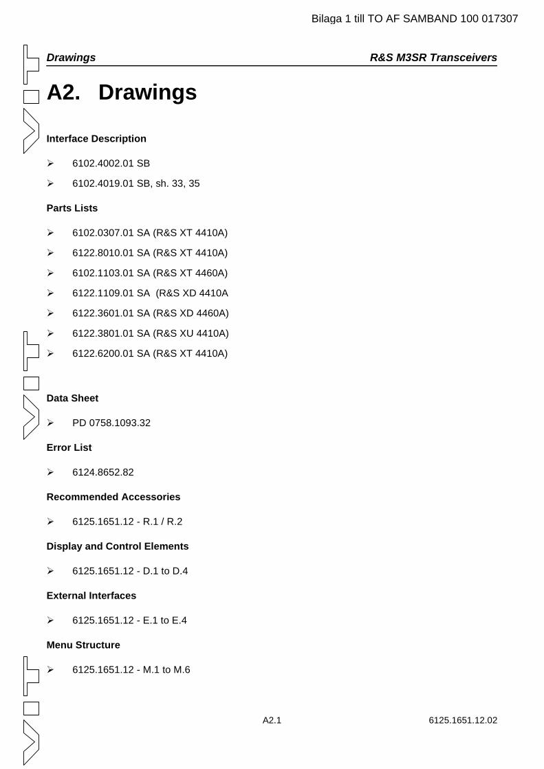
Drawings R&S M3SR Transceivers
A2.1 6125.1651.12.02
A2. Drawings
Interface Description
6102.4002.01 SB
6102.4019.01 SB, sh. 33, 35
Parts Lists
6102.0307.01 SA (R&S XT 4410A)
6122.8010.01 SA (R&S XT 4410A)
6102.1103.01 SA (R&S XT 4460A)
6122.1109.01 SA (R&S XD 4410A
6122.3601.01 SA (R&S XD 4460A)
6122.3801.01 SA (R&S XU 4410A)
6122.6200.01 SA (R&S XT 4410A)
Data Sheet
PD 0758.1093.32
Error List
6124.8652.82
Recommended Accessories
6125.1651.12 - R.1 / R.2
Display and Control Elements
6125.1651.12 - D.1 to D.4
External Interfaces
6125.1651.12 - E.1 to E.4
Menu Structure
6125.1651.12 - M.1 to M.6
Bilaga 1 till TO AF SAMBAND 100 017307
R&S M3SR Transceivers Drawings
Bilaga 1 till TO AF SAMBAND 100 017307
6125.1651.12.02 A2.2
Abt. / Dpt.: 2GE3 Name: Fl Datum / Date: 13.11.2007 Ä.I. / C.I.: 05.06
Benennung: M3SR ANLAGEN-DOKU Bl. / Sh. 1
ROHDE & SCHWARZ Designation: M3SR SYSTEM DOCU von / of 50
Typ / Type: M3SR Sprache / Language: en Materialnummer / material No.: 6102.4002.01 SBFür diese Unterlage behalten wir uns alle Rechte vor. Diese Unterlage ist ein Rechnerausdruck, Änderungen können nur durch Ändern des Datensatzes erfolgen. For this document all rights are reserved. This document is a computer printout, modifications can only be made in the data record.
Schnittstellenbeschreibung Interface Description
zu: M3SR ANLAGEN-DOKU Material-Nr.: 6102.4002.01 for: M3SR SYSTEM DOCU Material No.:
subject to change without notice due to technical improvements!
erstellt von: Friedl/2GEG Datum: 14.03.2003 issued by: Date:
Bilaga 1 till TO AF SAMBAND 100 017307
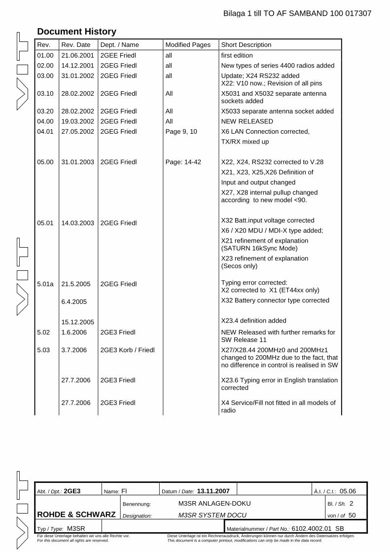
Abt. / Dpt.: 2GE3 Name: Fl Datum / Date: 13.11.2007 Ä.I. / C.I.: 05.06
Benennung: M3SR ANLAGEN-DOKU Bl. / Sh. 2
ROHDE & SCHWARZ Designation: M3SR SYSTEM DOCU von / of 50
Typ / Type: M3SR Materialnummer / Part No.: 6102.4002.01 SB Für diese Unterlage behalten wir uns alle Rechte vor. Diese Unterlage ist ein Rechnerausdruck, Änderungen können nur durch Ändern des Datensatzes erfolgen. For this document all rights are reserved. This document is a computer printout, modifications can only be made in the data record.
Document History Rev. Rev. Date Dept. / Name Modified Pages Short Description 01.00 21.06.2001 2GEE Friedl all first edition 02.00 14.12.2001 2GEG Friedl all New types of series 4400 radios added 03.00 31.01.2002 2GEG Friedl all Update; X24 RS232 added
X22: V10 now.; Revision of all pins 03.10 28.02.2002 2GEG Friedl All X5031 and X5032 separate antenna
sockets added 03.20 28.02.2002 2GEG Friedl All X5033 separate antenna socket added 04.00 19.03.2002 2GEG Friedl All NEW RELEASED 04.01
05.00
05.01
5.01a
27.05.2002
31.01.2003
14.03.2003
21.5.2005 6.4.2005 15.12.2005
2GEG Friedl
2GEG Friedl
2GEG Friedl
2GEG Friedl
Page 9, 10
Page: 14-42
X6 LAN Connection corrected, TX/RX mixed up X22, X24, RS232 corrected to V.28 X21, X23, X25,X26 Definition of Input and output changed X27, X28 internal pullup changed according to new model <90. X32 Batt.input voltage corrected X6 / X20 MDU / MDI-X type added; X21 refinement of explanation (SATURN 16kSync Mode) X23 refinement of explanation (Secos only)
Typing error corrected: X2 corrected to X1 (ET44xx only) X32 Battery connector type corrected X23.4 definition added
5.02 1.6.2006 2GE3 Friedl NEW Released with further remarks for SW Release 11
5.03 3.7.2006
27.7.2006
27.7.2006
2GE3 Korb / Friedl
2GE3 Friedl
2GE3 Friedl
X27/X28.44 200MHz0 and 200MHz1 changed to 200MHz due to the fact, that no difference in control is realised in SW
X23.6 Typing error in English translation corrected X4 Service/Fill not fitted in all models of radio
Bilaga 1 till TO AF SAMBAND 100 017307
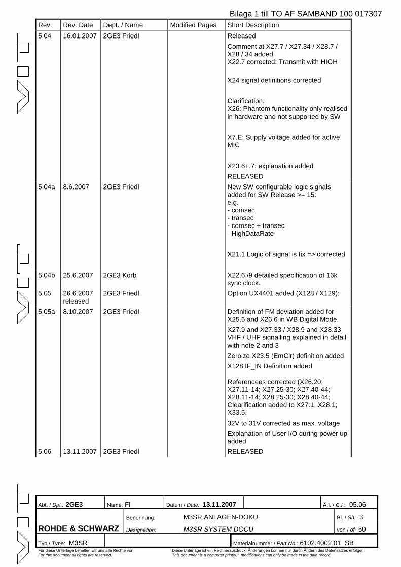
Abt. / Dpt.: 2GE3 Name: Fl Datum / Date: 13.11.2007 Ä.I. / C.I.: 05.06
Benennung: M3SR ANLAGEN-DOKU Bl. / Sh. 3
ROHDE & SCHWARZ Designation: M3SR SYSTEM DOCU von / of 50
Typ / Type: M3SR Materialnummer / Part No.: 6102.4002.01 SB Für diese Unterlage behalten wir uns alle Rechte vor. Diese Unterlage ist ein Rechnerausdruck, Änderungen können nur durch Ändern des Datensatzes erfolgen. For this document all rights are reserved. This document is a computer printout, modifications can only be made in the data record.
Rev. Rev. Date Dept. / Name Modified Pages Short Description 5.04 16.01.2007 2GE3 Friedl Released
Comment at X27.7 / X27.34 / X28.7 / X28 / 34 added. X22.7 corrected: Transmit with HIGH X24 signal definitions corrected Clarification: X26: Phantom functionality only realised in hardware and not supported by SW X7.E: Supply voltage added for active MIC X23.6+.7: explanation added RELEASED
5.04a 8.6.2007 2GE3 Friedl New SW configurable logic signals added for SW Release >= 15: e.g. - comsec - transec - comsec + transec - HighDataRate X21.1 Logic of signal is fix => corrected
5.04b 25.6.2007 2GE3 Korb X22.6./9 detailed specification of 16k sync clock.
5.05 26.6.2007 released
2GE3 Friedl Option UX4401 added (X128 / X129):
5.05a 8.10.2007 2GE3 Friedl Definition of FM deviation added for X25.6 and X26.6 in WB Digital Mode. X27.9 and X27.33 / X28.9 and X28.33 VHF / UHF signalling explained in detail with note 2 and 3 Zeroize X23.5 (EmClr) definition added X128 IF_IN Definition added Referencees corrected (X26.20; X27.11-14; X27.25-30; X27.40-44; X28.11-14; X28.25-30; X28.40-44; Clearification added to X27.1, X28.1; X33.5. 32V to 31V corrected as max. voltage Explanation of User I/O during power up added
5.06 13.11.2007 2GE3 Friedl RELEASED
Bilaga 1 till TO AF SAMBAND 100 017307
Abt. / Dpt.: 2GE3 Name: Fl Datum / Date: 13.11.2007 Ä.I. / C.I.: 05.06
Benennung: M3SR ANLAGEN-DOKU Bl. / Sh. 4
ROHDE & SCHWARZ Designation: M3SR SYSTEM DOCU von / of 50
Typ / Type: M3SR Materialnummer / Part No.: 6102.4002.01 SB Für diese Unterlage behalten wir uns alle Rechte vor. Diese Unterlage ist ein Rechnerausdruck, Änderungen können nur durch Ändern des Datensatzes erfolgen. For this document all rights are reserved. This document is a computer printout, modifications can only be made in the data record.
Inhalt / Contents Allgemeine Bemerkungen / General Remarks.................................................................................................................. 4 Konfigurierbarkeit ab SW Release 11 (Juni 2006) / SW-Configuration of HW Pins with SW >= Release 11/15: ......... 5 X1: Netzanschluß (nur ET 44xx) / Mains Connection (ET 44XX only) ................................................................... 6 X4: Service / Fill (HCCP).......................................................................................................................................... 6 X5: Service / Fill (HBASFP)..................................................................................................................................... 9 X6: Ethernet-Anschluß / Ethernet Connection .......................................................................................................... 11 X7: Anschluß Kopfsprechgarnitur / Headset Connection.......................................................................................... 12 X10: Referenzfrequenz-Eingang / Reference Frequency Input ................................................................................... 13 X11: Referenzfrequenz-Ausgang / Reference Frequency Output ............................................................................... 13 X20: Ethernet-Anschluß / Ethernet Connection .......................................................................................................... 13 X21: Verschiedenes 2 / Miscellaneous 2 ..................................................................................................................... 14 X22: RS232-Anschluß/ RS232 Connection................................................................................................................. 16 X23: Verschiedenes 1 / Miscellaneous 1 ..................................................................................................................... 17 X24: RS485 / RS422 / RS232 ..................................................................................................................................... 21 X25: NF-Schnittstelle 2 / AF Interface 2..................................................................................................................... 25 X26: NF-Schnittstelle 1 / AF Interface 1..................................................................................................................... 30 X27: Filter/Verstärkersteuerung 1 / Filter/Amplifier Control 1................................................................................... 37 X28: Filter/Verstärkersteuerung 2 / Filter/Amplifier Control 2................................................................................... 41 X30: Antenne/ RX / Antenna/RX................................................................................................................................ 45 X31: Netzanschluß (nur ST 44xx und XT 44xx) / Mains Connection (ST 44xx and XT 44xx only) ........................ 45 X32: Batterieanschluß / Battery Connection ............................................................................................................... 46 X33: Externe Stromversorgung / External Power Supply ........................................................................................... 47 X128: ZF Eingang 70MHz / IF Input 70MHz for special types only (option) .............................................................. 49 X129: ZF Ausgang 70MHz / IF Output 70MHz for special types only (option)........................................................... 49 X5031: Antenne RX / Antenna RX for special types only (option) ............................................................................... 50 X5032: Antenne GRX / Antenna GRX for special types only (option) .......................................................................... 50 X5033: Antenne RX/GRX / Antenna RX/GRX for special types only (option) ............................................................. 50
Allgemeine Bemerkungen / General Remarks · Signalnamen, denen das Zeichen ˜ vorangestellt ist, sind low-aktiv (z. B. ˜PTT_LINE_1). · ÜSS: Überspannungsschutz (Ein-/Ausgang ist gegen Spannungsspitzen geschützt) · Note 1) Phantom – PTT und Phantom-Squelch werden von der SW nicht unterstützt, sind aber in der HW realisiert.
· Signal names with leading ˜ are low-active (e. g. ˜PTT_LINE_1). · OVP: Over Voltage Protection – in-/output is protected against transient overvoltage. · Note 1) Phantom – PTT and Phantom-Squelch is (realized only by hardware and) not supported by software ! · Note 2) X27.9 VHF Signalling is High, if:
- PA VU220L is configured - PA VHF output pwr is configured (max. 25W @ AM; 35W@FM) - used frequency is between 118 and 143,975MHz in fixed frequency mode
· Note 3) X27.33 UHF Signalling is High, if: - PA VD480L is configured - PA UHF output pwr is configured (max. 35W @ AM; 50W@FM) - used frequency is between 225 and 399,975MHz in fixed frequency mode and SECOS
Bilaga 1 till TO AF SAMBAND 100 017307
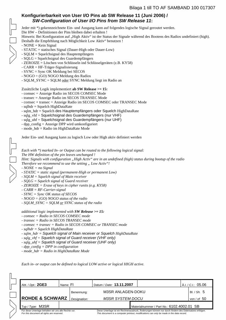
Abt. / Dpt.: 2GE3 Name: Fl Datum / Date: 13.11.2007 Ä.I. / C.I.: 05.06
Benennung: M3SR ANLAGEN-DOKU Bl. / Sh. 5
ROHDE & SCHWARZ Designation: M3SR SYSTEM DOCU von / of 50
Typ / Type: M3SR Materialnummer / Part No.: 6102.4002.01 SB Für diese Unterlage behalten wir uns alle Rechte vor. Diese Unterlage ist ein Rechnerausdruck, Änderungen können nur durch Ändern des Datensatzes erfolgen. For this document all rights are reserved. This document is a computer printout, modifications can only be made in the data record.
Konfigurierbarkeit von User I/O Pins ab SW Release 11 (Juni 2006) / SW-Configuration of User I/O Pins from SW Release 11:
Jeder mit *) gekennzeichnete Ein- und Ausgang kann auf folgendes logische Signal geroutet werden. Die HW – Definitionen der Pins bleiben dabei erhalten ! Hinweis: Bei Konfiguration auf „High Aktiv“ ist der Status der Signale während des Bootens des Radios undefiniert (high). Deshalb die Empfehlung nach Möglichkeit Low Aktiv“ benutzen ! - NONE = Kein Signal - STATIC = statisches Signal (Dauer-High oder Dauer-Low) - SQLM = Squelchsignal des Hauptempfängers - SQLG = Squelchsignal des Guardempfängers - ZEROIZE = Löschen von Schlüsseln ind Schlüsselgeräten (z.B. KY58) - CARR = HF-Träger-Signalisierung - SYNC = Sync OK Meldung bei SECOS - NOGO = (GO) NOGO Meldung des Radios - SQLM_SYNC = SQLM oder SYNC Meldung liegt im Radio an Zusätzliche Logik implementiert ab SW Release >= 15: - comsec = Anzeige Radio im SECOS COMSEC Mode - transec = Anzeige Radio im SECOS TRANSEC Mode - comsec + transec = Anzeige Radio im SECOS COMSEC oder TRANSEC Mode - sqlhdr = Squelch HighDataRate - sqlm_hdr = Squelch des Hauptempfängers oder Squelch HighDataRate - sqlg_vhf = Squelchsignal des Guardempfängers (nur VHF) - sqlg_uhf = Squelchsignal des Guardempfängers (nur UHF) - dpp_config = Anzeige DPP wird umkonfiguriert - mode_hdr = Radio im HighDataRate Mode Jeder Ein- und Ausgang kann zu logisch Low oder High aktiv definiert werden
Each with *) marked In- or Output can be routed to the following logical signal: The HW definition of the pin leaves unchanged ! Hint: Signals with configuration „High Activ“ are in an undefined (high) status during bootup of the radio Therefore we recommend to use the setting „ Low Activ“! - NONE = no Signal - STATIC = static signal (permanent-High or permanent Low) - SQLM = Squelch signal of Main receiver - SQLG = Squelch signal of Guard receiver - ZEROIZE = Erase of keys in cipher runits (e.g. KY58) - CARR = RF-Carrier-signal - SYNC = Sync OK status of SECOS - NOGO = (GO) NOGO status of the radio - SQLM_SYNC = SQLM or SYNC status of the radio additional logic implemented with SW Release >= 15: - comsec = Radio in SECOS COMSEC mode - transec = Radio in SECOS TRANSEC mode - comsec + transec = Radio in SECOS COMSEC or TRANSEC mode - sqlhdr = Squelch HighDataRate - sqlm_hdr = Squelch signal of Main receiver or Squelch HighDataRate - sqlg_vhf = Squelch signal of Guard receiver (VHF only) - sqlg_uhf = Squelch signal of Guard receiver (UHF only) - dpp_config = DPP in configuration - mode_hdr = Radio in HighDataRate Mode
Each in- or output can be defined to logical LOW active or logical HIGH active.
Bilaga 1 till TO AF SAMBAND 100 017307
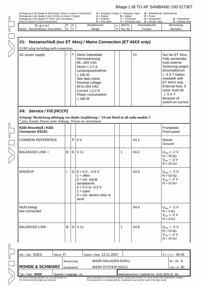
Eintragung in der Spalte R (Richtung) / Entry in column D (direction): O = Ausgang / Output I = Eingang / Input B = Bidirektional / Bidirectional Eintragung in der Spalte A (Art) / Entry in column T (type): A = Analog D = Digital P = Power Eintragung in der Spalte PT (Prüf- und Trimmplan) / P = Prüfwert T = Trimmwert D = Designwert E = Einstellwert Entry in column TI (test instructions): P = Test value T = Trimming value D = Design value E = Setting value
S i g n a l R A Wertebereich PT Bild Nr. Anschlußpunkt Bemerkung Name Beschreibung / Description D T Range TI Fig. No. Contact Remarks
Abt. / Dpt.: 2GE3 Name: Fl Datum / Date: 13.11.2007 Ä.I. / C.I.: 05.06
Benennung: M3SR ANLAGEN-DOKU Bl. / Sh. 6
ROHDE & SCHWARZ Designation: M3SR SYSTEM DOCU von / of 50
Typ / Type: M3SR Sprache / Language: en Materialnummer / material No.: 6102.4002.01 SBFür diese Unterlage behalten wir uns alle Rechte vor. Diese Unterlage ist ein Rechnerausdruck, Änderungen können nur durch Ändern des Datensatzes erfolgen. For this document all rights are reserved. This document is a computer printout, modifications can only be made in the data record.
X1: Netzanschluß (nur ET 44xx) / Mains Connection (ET 44XX only) EURO plug including earth connection.
AC power supply I P Siehe Datenblatt Nennspannung: 85...264 VAC Strom £ 2,2 A Leistungsaufnahme £ 190 W See data sheet Nominal voltage: 85 to 264 VAC Current £ 2.2 A Power consumption £ 190 W
X1 Nur bei ET 44xx.Falls verwendet, muß externe Sicherung wegen Einschaltstrom ³ 5 A T haben Available with ET 44XX only. External fuse, if used, must be ³ 5 A Tbecause of switch-on current
X4: Service / Fill (HCCP) Achtung! Bestückung abhängig von Radio-Ausführung ! X4 not fitted in all radio models !! 7 pins, female; Pinout siehe Anhang / Pinout see attachment
KDD-Anschluß / KDD Connector DS101
Frontplatte Front panel
COMMON REFERENCE P 0 V X4.1 Masse Ground
BALANCED LINE + B D V.11 1 X4.2 Uaus = -2 V Ri = 20 kWVout = -2 V Ri = 20 kW
WAKEUP I D 0 = 0 V...-0,5 V 1 = offen 0 = ext. Gerät sendebereit 0 = 0 V to -0.5 V 1 = open 0 = ext. device clear to send
X4.3 Uaus = -2 V Ri = 52 kWVout = -2 V Ri = 52 kW
Nicht belegt Not connected
X4.4 Uaus = -2 V Ri = 4 kWVout = -2 V Ri = 4 kW
BALANCED LINE - B D V.11 1 X4.5 Uaus = -2 V Ri = 20 kWVout = -2 V Ri = 20 kW
Bilaga 1 till TO AF SAMBAND 100 017307
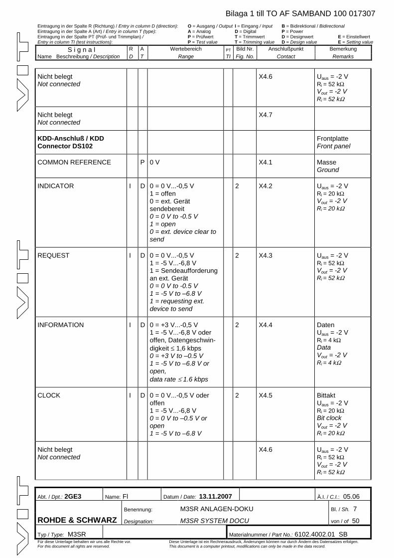
Eintragung in der Spalte R (Richtung) / Entry in column D (direction): O = Ausgang / Output I = Eingang / Input B = Bidirektional / Bidirectional Eintragung in der Spalte A (Art) / Entry in column T (type): A = Analog D = Digital P = Power Eintragung in der Spalte PT (Prüf- und Trimmplan) / P = Prüfwert T = Trimmwert D = Designwert E = Einstellwert Entry in column TI (test instructions): P = Test value T = Trimming value D = Design value E = Setting value
S i g n a l R A Wertebereich PT Bild Nr. Anschlußpunkt Bemerkung Name Beschreibung / Description D T Range TI Fig. No. Contact Remarks
Abt. / Dpt.: 2GE3 Name: Fl Datum / Date: 13.11.2007 Ä.I. / C.I.: 05.06
Benennung: M3SR ANLAGEN-DOKU Bl. / Sh. 7
ROHDE & SCHWARZ Designation: M3SR SYSTEM DOCU von / of 50
Typ / Type: M3SR Materialnummer / Part No.: 6102.4002.01 SB Für diese Unterlage behalten wir uns alle Rechte vor. Diese Unterlage ist ein Rechnerausdruck, Änderungen können nur durch Ändern des Datensatzes erfolgen. For this document all rights are reserved. This document is a computer printout, modifications can only be made in the data record.
Nicht belegt Not connected
X4.6 Uaus = -2 V Ri = 52 kWVout = -2 V Ri = 52 kW
Nicht belegt Not connected
X4.7
KDD-Anschluß / KDD Connector DS102
Frontplatte Front panel
COMMON REFERENCE P 0 V X4.1 Masse Ground
INDICATOR I D 0 = 0 V...-0,5 V 1 = offen 0 = ext. Gerät sendebereit 0 = 0 V to -0.5 V 1 = open 0 = ext. device clear to send
2 X4.2 Uaus = -2 V Ri = 20 kWVout = -2 V Ri = 20 kW
REQUEST I D 0 = 0 V...-0,5 V 1 = -5 V...-6,8 V 1 = Sendeaufforderung an ext. Gerät 0 = 0 V to -0.5 V 1 = -5 V to –6.8 V 1 = requesting ext. device to send
2 X4.3 Uaus = -2 V Ri = 52 kWVout = -2 V Ri = 52 kW
INFORMATION
I D 0 = +3 V...-0,5 V 1 = -5 V...-6,8 V oder offen, Datengeschwin-digkeit £ 1,6 kbps 0 = +3 V to –0.5 V 1 = -5 V to –6.8 V or open, data rate £ 1.6 kbps
2 X4.4 Daten Uaus = -2 V Ri = 4 kWData Vout = -2 V Ri = 4 kW
CLOCK I D 0 = 0 V...-0,5 V oder offen 1 = -5 V...-6,8 V 0 = 0 V to –0.5 V or open 1 = -5 V to –6.8 V
2 X4.5 Bittakt Uaus = -2 V Ri = 20 kWBit clock Vout = -2 V Ri = 20 kW
Nicht belegt Not connected
X4.6 Uaus = -2 V Ri = 52 kWVout = -2 V Ri = 52 kW
Bilaga 1 till TO AF SAMBAND 100 017307
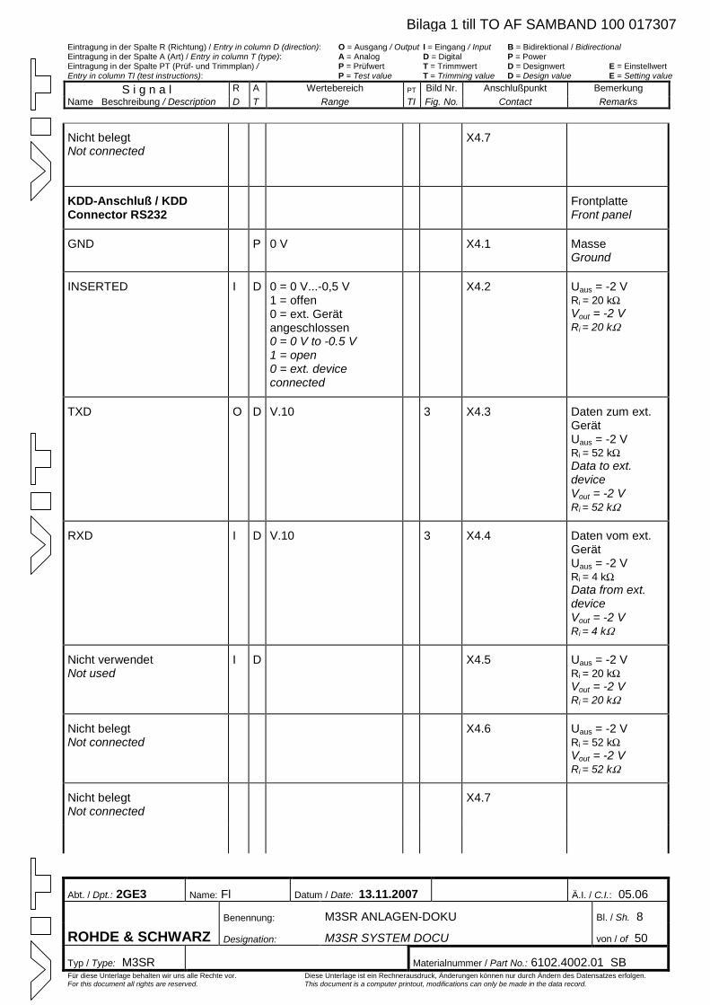
Eintragung in der Spalte R (Richtung) / Entry in column D (direction): O = Ausgang / Output I = Eingang / Input B = Bidirektional / Bidirectional Eintragung in der Spalte A (Art) / Entry in column T (type): A = Analog D = Digital P = Power Eintragung in der Spalte PT (Prüf- und Trimmplan) / P = Prüfwert T = Trimmwert D = Designwert E = Einstellwert Entry in column TI (test instructions): P = Test value T = Trimming value D = Design value E = Setting value
S i g n a l R A Wertebereich PT Bild Nr. Anschlußpunkt Bemerkung Name Beschreibung / Description D T Range TI Fig. No. Contact Remarks
Abt. / Dpt.: 2GE3 Name: Fl Datum / Date: 13.11.2007 Ä.I. / C.I.: 05.06
Benennung: M3SR ANLAGEN-DOKU Bl. / Sh. 8
ROHDE & SCHWARZ Designation: M3SR SYSTEM DOCU von / of 50
Typ / Type: M3SR Materialnummer / Part No.: 6102.4002.01 SB Für diese Unterlage behalten wir uns alle Rechte vor. Diese Unterlage ist ein Rechnerausdruck, Änderungen können nur durch Ändern des Datensatzes erfolgen. For this document all rights are reserved. This document is a computer printout, modifications can only be made in the data record.
Nicht belegt Not connected
X4.7
KDD-Anschluß / KDD Connector RS232
Frontplatte Front panel
GND P 0 V X4.1 Masse Ground
INSERTED I D 0 = 0 V...-0,5 V 1 = offen 0 = ext. Gerät angeschlossen 0 = 0 V to -0.5 V 1 = open 0 = ext. device connected
X4.2 Uaus = -2 V Ri = 20 kWVout = -2 V Ri = 20 kW
TXD O D V.10 3 X4.3 Daten zum ext. Gerät Uaus = -2 V Ri = 52 kWData to ext. device Vout = -2 V Ri = 52 kW
RXD
I D V.10 3 X4.4 Daten vom ext. Gerät Uaus = -2 V Ri = 4 kWData from ext. device Vout = -2 V Ri = 4 kW
Nicht verwendet Not used
I D X4.5 Uaus = -2 V Ri = 20 kWVout = -2 V Ri = 20 kW
Nicht belegt Not connected
X4.6 Uaus = -2 V Ri = 52 kWVout = -2 V Ri = 52 kW
Nicht belegt Not connected
X4.7
Bilaga 1 till TO AF SAMBAND 100 017307
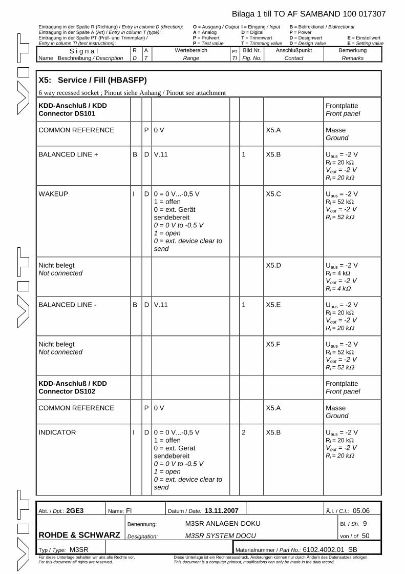
Eintragung in der Spalte R (Richtung) / Entry in column D (direction): O = Ausgang / Output I = Eingang / Input B = Bidirektional / Bidirectional Eintragung in der Spalte A (Art) / Entry in column T (type): A = Analog D = Digital P = Power Eintragung in der Spalte PT (Prüf- und Trimmplan) / P = Prüfwert T = Trimmwert D = Designwert E = Einstellwert Entry in column TI (test instructions): P = Test value T = Trimming value D = Design value E = Setting value
S i g n a l R A Wertebereich PT Bild Nr. Anschlußpunkt Bemerkung Name Beschreibung / Description D T Range TI Fig. No. Contact Remarks
Abt. / Dpt.: 2GE3 Name: Fl Datum / Date: 13.11.2007 Ä.I. / C.I.: 05.06
Benennung: M3SR ANLAGEN-DOKU Bl. / Sh. 9
ROHDE & SCHWARZ Designation: M3SR SYSTEM DOCU von / of 50
Typ / Type: M3SR Materialnummer / Part No.: 6102.4002.01 SB Für diese Unterlage behalten wir uns alle Rechte vor. Diese Unterlage ist ein Rechnerausdruck, Änderungen können nur durch Ändern des Datensatzes erfolgen. For this document all rights are reserved. This document is a computer printout, modifications can only be made in the data record.
X5: Service / Fill (HBASFP) 6 way recessed socket ; Pinout siehe Anhang / Pinout see attachment
KDD-Anschluß / KDD Connector DS101
Frontplatte Front panel
COMMON REFERENCE P 0 V X5.A Masse Ground
BALANCED LINE + B D V.11 1 X5.B Uaus = -2 V Ri = 20 kWVout = -2 V Ri = 20 kW
WAKEUP I D 0 = 0 V...-0,5 V 1 = offen 0 = ext. Gerät sendebereit 0 = 0 V to -0.5 V 1 = open 0 = ext. device clear to send
X5.C Uaus = -2 V Ri = 52 kWVout = -2 V Ri = 52 kW
Nicht belegt Not connected
X5.D Uaus = -2 V Ri = 4 kWVout = -2 V Ri = 4 kW
BALANCED LINE - B D V.11 1 X5.E Uaus = -2 V Ri = 20 kWVout = -2 V Ri = 20 kW
Nicht belegt Not connected
X5.F Uaus = -2 V Ri = 52 kWVout = -2 V Ri = 52 kW
KDD-Anschluß / KDD Connector DS102
Frontplatte Front panel
COMMON REFERENCE P 0 V X5.A Masse Ground
INDICATOR I D 0 = 0 V...-0,5 V 1 = offen 0 = ext. Gerät sendebereit 0 = 0 V to -0.5 V 1 = open 0 = ext. device clear to send
2 X5.B Uaus = -2 V Ri = 20 kWVout = -2 V Ri = 20 kW
Bilaga 1 till TO AF SAMBAND 100 017307
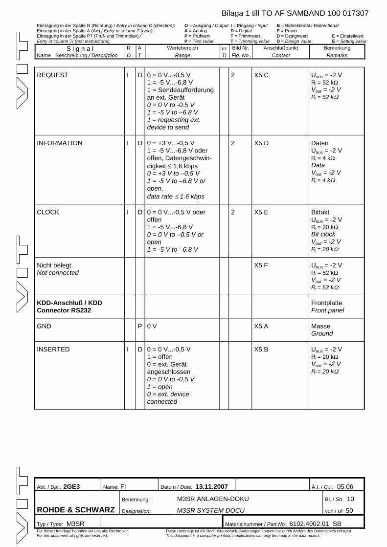
Eintragung in der Spalte R (Richtung) / Entry in column D (direction): O = Ausgang / Output I = Eingang / Input B = Bidirektional / Bidirectional Eintragung in der Spalte A (Art) / Entry in column T (type): A = Analog D = Digital P = Power Eintragung in der Spalte PT (Prüf- und Trimmplan) / P = Prüfwert T = Trimmwert D = Designwert E = Einstellwert Entry in column TI (test instructions): P = Test value T = Trimming value D = Design value E = Setting value
S i g n a l R A Wertebereich PT Bild Nr. Anschlußpunkt Bemerkung Name Beschreibung / Description D T Range TI Fig. No. Contact Remarks
Abt. / Dpt.: 2GE3 Name: Fl Datum / Date: 13.11.2007 Ä.I. / C.I.: 05.06
Benennung: M3SR ANLAGEN-DOKU Bl. / Sh. 10
ROHDE & SCHWARZ Designation: M3SR SYSTEM DOCU von / of 50
Typ / Type: M3SR Materialnummer / Part No.: 6102.4002.01 SB Für diese Unterlage behalten wir uns alle Rechte vor. Diese Unterlage ist ein Rechnerausdruck, Änderungen können nur durch Ändern des Datensatzes erfolgen. For this document all rights are reserved. This document is a computer printout, modifications can only be made in the data record.
REQUEST I D 0 = 0 V...-0,5 V 1 = -5 V...-6,8 V 1 = Sendeaufforderung an ext. Gerät 0 = 0 V to -0.5 V 1 = -5 V to –6.8 V 1 = requesting ext. device to send
2 X5.C Uaus = -2 V Ri = 52 kWVout = -2 V Ri = 52 kW
INFORMATION
I D 0 = +3 V...-0,5 V 1 = -5 V...-6,8 V oder offen, Datengeschwin-digkeit £ 1,6 kbps 0 = +3 V to –0.5 V 1 = -5 V to –6.8 V or open, data rate £ 1.6 kbps
2 X5.D Daten Uaus = -2 V Ri = 4 kWData Vout = -2 V Ri = 4 kW
CLOCK I D 0 = 0 V...-0,5 V oder offen 1 = -5 V...-6,8 V 0 = 0 V to –0.5 V or open 1 = -5 V to –6.8 V
2 X5.E Bittakt Uaus = -2 V Ri = 20 kWBit clock Vout = -2 V Ri = 20 kW
Nicht belegt Not connected
X5.F Uaus = -2 V Ri = 52 kWVout = -2 V Ri = 52 kW
KDD-Anschluß / KDD Connector RS232
Frontplatte Front panel
GND P 0 V X5.A Masse Ground
INSERTED I D 0 = 0 V...-0,5 V 1 = offen 0 = ext. Gerät angeschlossen 0 = 0 V to -0.5 V 1 = open 0 = ext. device connected
X5.B Uaus = -2 V Ri = 20 kWVout = -2 V Ri = 20 kW
Bilaga 1 till TO AF SAMBAND 100 017307
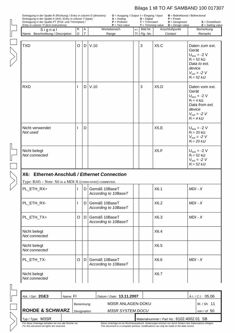
Eintragung in der Spalte R (Richtung) / Entry in column D (direction): O = Ausgang / Output I = Eingang / Input B = Bidirektional / Bidirectional Eintragung in der Spalte A (Art) / Entry in column T (type): A = Analog D = Digital P = Power Eintragung in der Spalte PT (Prüf- und Trimmplan) / P = Prüfwert T = Trimmwert D = Designwert E = Einstellwert Entry in column TI (test instructions): P = Test value T = Trimming value D = Design value E = Setting value
S i g n a l R A Wertebereich PT Bild Nr. Anschlußpunkt Bemerkung Name Beschreibung / Description D T Range TI Fig. No. Contact Remarks
Abt. / Dpt.: 2GE3 Name: Fl Datum / Date: 13.11.2007 Ä.I. / C.I.: 05.06
Benennung: M3SR ANLAGEN-DOKU Bl. / Sh. 11
ROHDE & SCHWARZ Designation: M3SR SYSTEM DOCU von / of 50
Typ / Type: M3SR Materialnummer / Part No.: 6102.4002.01 SB Für diese Unterlage behalten wir uns alle Rechte vor. Diese Unterlage ist ein Rechnerausdruck, Änderungen können nur durch Ändern des Datensatzes erfolgen. For this document all rights are reserved. This document is a computer printout, modifications can only be made in the data record.
TXD O D V.10 3 X5.C Daten zum ext. Gerät Uaus = -2 V Ri = 52 kWData to ext. device Vout = -2 V Ri = 52 kW
RXD
I D V.10 3 X5.D Daten vom ext. Gerät Uaus = -2 V Ri = 4 kWData from ext. device Vout = -2 V Ri = 4 kW
Nicht verwendet Not used
I D X5.E Uaus = -2 V Ri = 20 kWVout = -2 V Ri = 20 kW
Nicht belegt Not connected
X5.F Uaus = -2 V Ri = 52 kWVout = -2 V Ri = 52 kW
X6: Ethernet-Anschluß / Ethernet Connection Type: RJ45 – Note: X6 is a MDI-X (cross-over) connector.
PL_ETH_RX+ I D Gemäß 10BaseT According to 10BaseT
X6.1 MDI - X
PL_ETH_RX- I D Gemäß 10BaseT According to 10BaseT
X6.2 MDI - X
PL_ETH_TX+ O D Gemäß 10BaseT According to 10BaseT
X6.3 MDI - X
Nicht belegt Not connected
X6.4
Nicht belegt Not connected
X6.5
PL_ETH_TX- O D Gemäß 10BaseT According to 10BaseT
X6.6 MDI - X
Nicht belegt Not connected
X6.7
Bilaga 1 till TO AF SAMBAND 100 017307
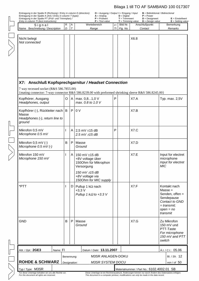
Eintragung in der Spalte R (Richtung) / Entry in column D (direction): O = Ausgang / Output I = Eingang / Input B = Bidirektional / Bidirectional Eintragung in der Spalte A (Art) / Entry in column T (type): A = Analog D = Digital P = Power Eintragung in der Spalte PT (Prüf- und Trimmplan) / P = Prüfwert T = Trimmwert D = Designwert E = Einstellwert Entry in column TI (test instructions): P = Test value T = Trimming value D = Design value E = Setting value
S i g n a l R A Wertebereich PT Bild Nr. Anschlußpunkt Bemerkung Name Beschreibung / Description D T Range TI Fig. No. Contact Remarks
Abt. / Dpt.: 2GE3 Name: Fl Datum / Date: 13.11.2007 Ä.I. / C.I.: 05.06
Benennung: M3SR ANLAGEN-DOKU Bl. / Sh. 12
ROHDE & SCHWARZ Designation: M3SR SYSTEM DOCU von / of 50
Typ / Type: M3SR Materialnummer / Part No.: 6102.4002.01 SB Für diese Unterlage behalten wir uns alle Rechte vor. Diese Unterlage ist ein Rechnerausdruck, Änderungen können nur durch Ändern des Datensatzes erfolgen. For this document all rights are reserved. This document is a computer printout, modifications can only be made in the data record.
Nicht belegt Not connected
X6.8
X7: Anschluß Kopfsprechgarnitur / Headset Connection 7 way recessed socket (R&S 586.7855.00) mating connector: 7-way connector R&S 586.8239.00 with preformed shrinking sleeve R&S 586.8245.00
Kopfhörer, Ausgang Headphones, output
O A max. 0,8...1,0 V max. 0.8 to 1.0 V
P X7.A Typ. max. 2,5V
Kopfhörer (-), Rückleiter nach Masse Headphones (-), return line to ground
B P 0 V X7.B
Mikrofon 0,5 mV Microphone 0.5 mV
I A 2,5 mV ±15 dB 2.5 mV ±15 dB
P X7.C
Mikrofon 0,5 mV (-) Microphone 0.5 mV (-)
B P Masse Ground
X7.D
Mikrofon 150 mV Microphone 150 mV
I A 150 mV ±15 dB +8V voltage über 150Ohm für Mikrophon Versorgung
150 mV ±15 dB +8V voltage via 150Ohm for MIC supply
X7.E Input for electret microphone Input for electret MIC
*PTT I D Pullup 1 kW nach +3,3 V Pullup 1 kW to +3.3 V
X7.F Kontakt nach Masse = Senden, offen = Sendepause Contact to GND = transmit; open = no transmit
GND B P Masse Ground
X7.G Zu Mikrofon 150 mV und PTT-Taste For microphone 150 mV and PTT switch
Bilaga 1 till TO AF SAMBAND 100 017307
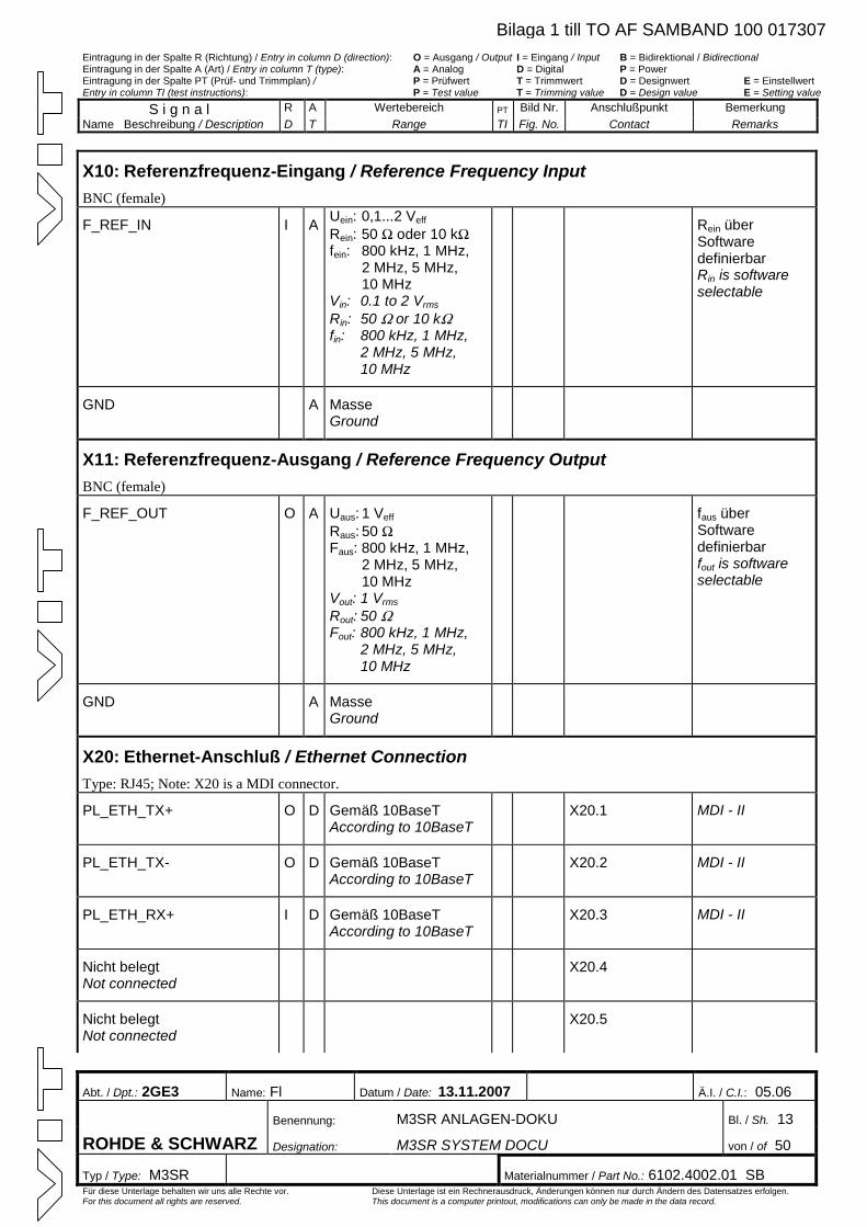
Eintragung in der Spalte R (Richtung) / Entry in column D (direction): O = Ausgang / Output I = Eingang / Input B = Bidirektional / Bidirectional Eintragung in der Spalte A (Art) / Entry in column T (type): A = Analog D = Digital P = Power Eintragung in der Spalte PT (Prüf- und Trimmplan) / P = Prüfwert T = Trimmwert D = Designwert E = Einstellwert Entry in column TI (test instructions): P = Test value T = Trimming value D = Design value E = Setting value
S i g n a l R A Wertebereich PT Bild Nr. Anschlußpunkt Bemerkung Name Beschreibung / Description D T Range TI Fig. No. Contact Remarks
Abt. / Dpt.: 2GE3 Name: Fl Datum / Date: 13.11.2007 Ä.I. / C.I.: 05.06
Benennung: M3SR ANLAGEN-DOKU Bl. / Sh. 13
ROHDE & SCHWARZ Designation: M3SR SYSTEM DOCU von / of 50
Typ / Type: M3SR Materialnummer / Part No.: 6102.4002.01 SB Für diese Unterlage behalten wir uns alle Rechte vor. Diese Unterlage ist ein Rechnerausdruck, Änderungen können nur durch Ändern des Datensatzes erfolgen. For this document all rights are reserved. This document is a computer printout, modifications can only be made in the data record.
X10: Referenzfrequenz-Eingang / Reference Frequency Input BNC (female)
F_REF_IN I A Uein: 0,1...2 Veff Rein: 50 W oder 10 kWfein: 800 kHz, 1 MHz,
2 MHz, 5 MHz, 10 MHz
Vin: 0.1 to 2 Vrms Rin: 50 W or 10 kWfin: 800 kHz, 1 MHz,
2 MHz, 5 MHz, 10 MHz
Rein über Software definierbar Rin is software selectable
GND A Masse Ground
X11: Referenzfrequenz-Ausgang / Reference Frequency Output BNC (female)
F_REF_OUT O A Uaus: 1 Veff
Raus: 50 WFaus: 800 kHz, 1 MHz,
2 MHz, 5 MHz, 10 MHz
Vout: 1 Vrms Rout: 50 WFout: 800 kHz, 1 MHz,
2 MHz, 5 MHz, 10 MHz
faus über Software definierbar fout is software selectable
GND A Masse Ground
X20: Ethernet-Anschluß / Ethernet Connection Type: RJ45; Note: X20 is a MDI connector.
PL_ETH_TX+ O D Gemäß 10BaseT According to 10BaseT
X20.1 MDI - II
PL_ETH_TX- O D Gemäß 10BaseT According to 10BaseT
X20.2 MDI - II
PL_ETH_RX+ I D Gemäß 10BaseT According to 10BaseT
X20.3 MDI - II
Nicht belegt Not connected
X20.4
Nicht belegt Not connected
X20.5
Bilaga 1 till TO AF SAMBAND 100 017307
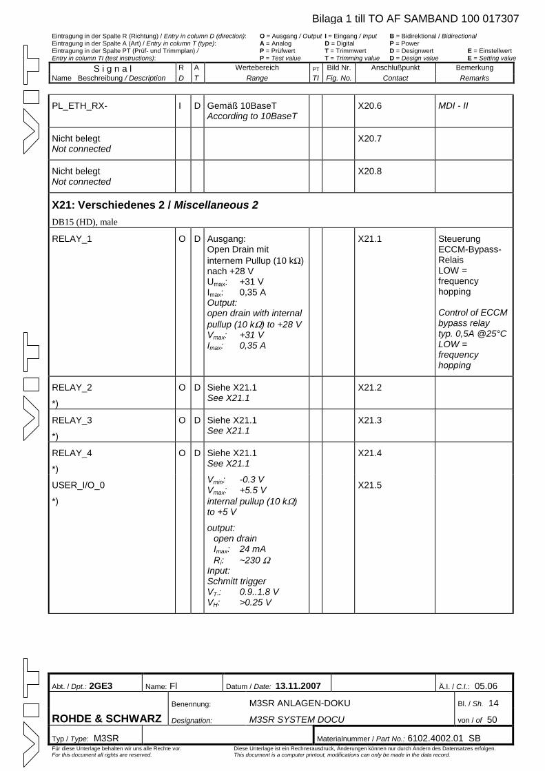
Eintragung in der Spalte R (Richtung) / Entry in column D (direction): O = Ausgang / Output I = Eingang / Input B = Bidirektional / Bidirectional Eintragung in der Spalte A (Art) / Entry in column T (type): A = Analog D = Digital P = Power Eintragung in der Spalte PT (Prüf- und Trimmplan) / P = Prüfwert T = Trimmwert D = Designwert E = Einstellwert Entry in column TI (test instructions): P = Test value T = Trimming value D = Design value E = Setting value
S i g n a l R A Wertebereich PT Bild Nr. Anschlußpunkt Bemerkung Name Beschreibung / Description D T Range TI Fig. No. Contact Remarks
Abt. / Dpt.: 2GE3 Name: Fl Datum / Date: 13.11.2007 Ä.I. / C.I.: 05.06
Benennung: M3SR ANLAGEN-DOKU Bl. / Sh. 14
ROHDE & SCHWARZ Designation: M3SR SYSTEM DOCU von / of 50
Typ / Type: M3SR Materialnummer / Part No.: 6102.4002.01 SB Für diese Unterlage behalten wir uns alle Rechte vor. Diese Unterlage ist ein Rechnerausdruck, Änderungen können nur durch Ändern des Datensatzes erfolgen. For this document all rights are reserved. This document is a computer printout, modifications can only be made in the data record.
PL_ETH_RX- I D Gemäß 10BaseT According to 10BaseT
X20.6 MDI - II
Nicht belegt Not connected
X20.7
Nicht belegt Not connected
X20.8
X21: Verschiedenes 2 / Miscellaneous 2 DB15 (HD), male
RELAY_1
O D Ausgang: Open Drain mit internem Pullup (10 kW)nach +28 V Umax: +31 V Imax: 0,35 A Output: open drain with internal pullup (10 kW) to +28 VVmax: +31 V Imax: 0,35 A
X21.1 Steuerung ECCM-Bypass-Relais LOW = frequency hopping Control of ECCM bypass relay typ. 0,5A @25°CLOW = frequency hopping
RELAY_2
*)
O D Siehe X21.1 See X21.1
X21.2
RELAY_3
*)
O D Siehe X21.1 See X21.1
X21.3
RELAY_4
*)
O D Siehe X21.1 See X21.1
X21.4
USER_I/O_0
*)
Vmin: -0.3 V Vmax: +5.5 V internal pullup (10 kW)to +5 V
output: open drain Imax: 24 mA Ri: ~230 W
Input: Schmitt trigger VT-: 0.9..1.8 V VH: >0.25 V
X21.5
Bilaga 1 till TO AF SAMBAND 100 017307
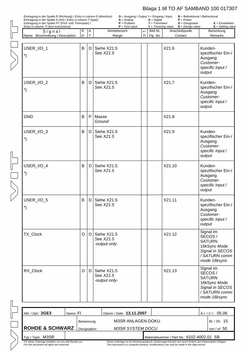
Eintragung in der Spalte R (Richtung) / Entry in column D (direction): O = Ausgang / Output I = Eingang / Input B = Bidirektional / Bidirectional Eintragung in der Spalte A (Art) / Entry in column T (type): A = Analog D = Digital P = Power Eintragung in der Spalte PT (Prüf- und Trimmplan) / P = Prüfwert T = Trimmwert D = Designwert E = Einstellwert Entry in column TI (test instructions): P = Test value T = Trimming value D = Design value E = Setting value
S i g n a l R A Wertebereich PT Bild Nr. Anschlußpunkt Bemerkung Name Beschreibung / Description D T Range TI Fig. No. Contact Remarks
Abt. / Dpt.: 2GE3 Name: Fl Datum / Date: 13.11.2007 Ä.I. / C.I.: 05.06
Benennung: M3SR ANLAGEN-DOKU Bl. / Sh. 15
ROHDE & SCHWARZ Designation: M3SR SYSTEM DOCU von / of 50
Typ / Type: M3SR Materialnummer / Part No.: 6102.4002.01 SB Für diese Unterlage behalten wir uns alle Rechte vor. Diese Unterlage ist ein Rechnerausdruck, Änderungen können nur durch Ändern des Datensatzes erfolgen. For this document all rights are reserved. This document is a computer printout, modifications can only be made in the data record.
USER_I/O_1
*)
B D Siehe X21.5 See X21.5
X21.6 Kunden-spezifischer Ein-/ Ausgang Customer-specific input / output
USER_I/O_2
*)
B D Siehe X21.5 See X21.5
X21.7 Kunden-spezifischer Ein-/ Ausgang Customer-specific input / output
GND B P Masse Ground
X21.8
USER_I/O_3
*)
B D Siehe X21.5 See X21.5
X21.9 Kunden-spezifischer Ein-/ Ausgang Customer-specific input / output
USER_I/O_4
*)
B D Siehe X21.5 See X21.5
X21.10 Kunden-spezifischer Ein-/ Ausgang Customer-specific input / output
USER_I/O_5
*)
B D Siehe X21.5 See X21.5
X21.11 Kunden-spezifischer Ein-/ Ausgang Customer-specific input / output
TX_Clock O D Siehe X21.5 See X21.5 -output only-
X21.12 Signal im SECOS / SATURN 16kSync Mode Signal in SECOS / SATURN comm mode 16ksync
RX_Clock O D Siehe X21.5 See X21.5 -output only-
X21.13 Signal im SECOS / SATURN 16kSync Mode Signal in SECOS / SATURN comm mode 16ksync
Bilaga 1 till TO AF SAMBAND 100 017307
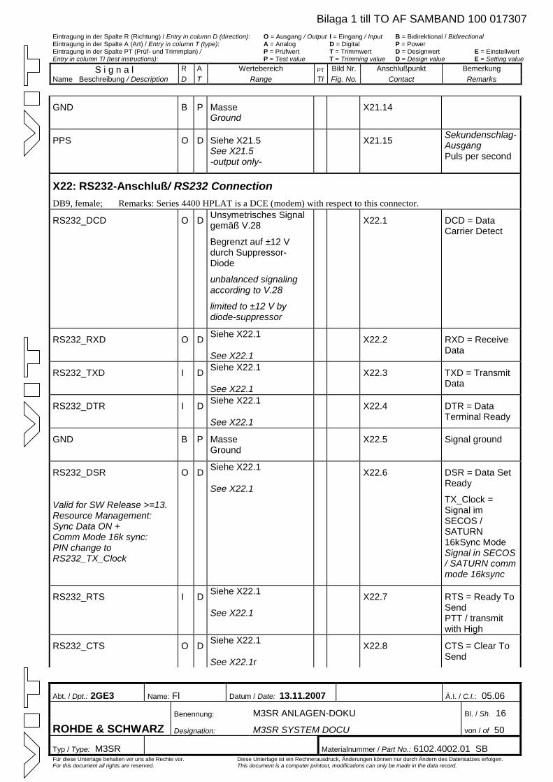
Eintragung in der Spalte R (Richtung) / Entry in column D (direction): O = Ausgang / Output I = Eingang / Input B = Bidirektional / Bidirectional Eintragung in der Spalte A (Art) / Entry in column T (type): A = Analog D = Digital P = Power Eintragung in der Spalte PT (Prüf- und Trimmplan) / P = Prüfwert T = Trimmwert D = Designwert E = Einstellwert Entry in column TI (test instructions): P = Test value T = Trimming value D = Design value E = Setting value
S i g n a l R A Wertebereich PT Bild Nr. Anschlußpunkt Bemerkung Name Beschreibung / Description D T Range TI Fig. No. Contact Remarks
Abt. / Dpt.: 2GE3 Name: Fl Datum / Date: 13.11.2007 Ä.I. / C.I.: 05.06
Benennung: M3SR ANLAGEN-DOKU Bl. / Sh. 16
ROHDE & SCHWARZ Designation: M3SR SYSTEM DOCU von / of 50
Typ / Type: M3SR Materialnummer / Part No.: 6102.4002.01 SB Für diese Unterlage behalten wir uns alle Rechte vor. Diese Unterlage ist ein Rechnerausdruck, Änderungen können nur durch Ändern des Datensatzes erfolgen. For this document all rights are reserved. This document is a computer printout, modifications can only be made in the data record.
GND B P Masse Ground
X21.14
PPS O D Siehe X21.5 See X21.5 -output only-
X21.15 Sekundenschlag-Ausgang Puls per second
X22: RS232-Anschluß/ RS232 Connection DB9, female; Remarks: Series 4400 HPLAT is a DCE (modem) with respect to this connector.
RS232_DCD O D Unsymetrisches Signal gemäß V.28
Begrenzt auf ±12 V durch Suppressor-Diode
unbalanced signaling according to V.28
limited to ±12 V by diode-suppressor
X22.1 DCD = Data Carrier Detect
RS232_RXD O D Siehe X22.1
See X22.1
X22.2 RXD = Receive Data
RS232_TXD I D Siehe X22.1
See X22.1
X22.3 TXD = Transmit Data
RS232_DTR I D Siehe X22.1
See X22.1
X22.4 DTR = Data Terminal Ready
GND B P Masse Ground
X22.5 Signal ground
RS232_DSR
Valid for SW Release >=13. Resource Management: Sync Data ON + Comm Mode 16k sync: PIN change to RS232_TX_Clock
O D Siehe X22.1
See X22.1
X22.6 DSR = Data Set Ready
TX_Clock = Signal im SECOS / SATURN 16kSync Mode Signal in SECOS / SATURN comm mode 16ksync
RS232_RTS I D Siehe X22.1
See X22.1
X22.7 RTS = Ready To Send PTT / transmit with High
RS232_CTS O D Siehe X22.1
See X22.1r
X22.8 CTS = Clear To Send
Bilaga 1 till TO AF SAMBAND 100 017307
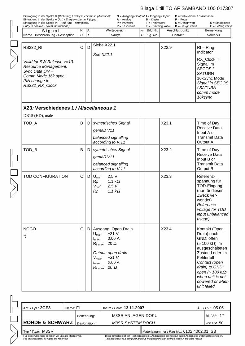
Eintragung in der Spalte R (Richtung) / Entry in column D (direction): O = Ausgang / Output I = Eingang / Input B = Bidirektional / Bidirectional Eintragung in der Spalte A (Art) / Entry in column T (type): A = Analog D = Digital P = Power Eintragung in der Spalte PT (Prüf- und Trimmplan) / P = Prüfwert T = Trimmwert D = Designwert E = Einstellwert Entry in column TI (test instructions): P = Test value T = Trimming value D = Design value E = Setting value
S i g n a l R A Wertebereich PT Bild Nr. Anschlußpunkt Bemerkung Name Beschreibung / Description D T Range TI Fig. No. Contact Remarks
Abt. / Dpt.: 2GE3 Name: Fl Datum / Date: 13.11.2007 Ä.I. / C.I.: 05.06
Benennung: M3SR ANLAGEN-DOKU Bl. / Sh. 17
ROHDE & SCHWARZ Designation: M3SR SYSTEM DOCU von / of 50
Typ / Type: M3SR Materialnummer / Part No.: 6102.4002.01 SB Für diese Unterlage behalten wir uns alle Rechte vor. Diese Unterlage ist ein Rechnerausdruck, Änderungen können nur durch Ändern des Datensatzes erfolgen. For this document all rights are reserved. This document is a computer printout, modifications can only be made in the data record.
RS232_RI
Valid for SW Release >=13. Resource Management: Sync Data ON + Comm Mode 16k sync: PIN change to RS232_RX_Clock
O D Siehe X22.1
See X22.1
X22.9 RI – Ring Indicator
RX_Clock = Signal im SECOS / SATURN 16kSync Mode Signal in SECOS / SATURN comm mode 16ksync
X23: Verschiedenes 1 / Miscellaneous 1 DB15 (HD), male
TOD_A B D symetrisches Signal
gemäß V11
balanced signalling according to V.11
X23.1 Time of Day Receive Data Input A or Transmit Data Output A
TOD_B B D symetrisches Signal
gemäß V11
balanced signalling according to V.11
X23.2 Time of Day Receive Data Input B or Transmit Data Output B
TOD CONFIGURATION O D Uaus: 2,5 V RI: 1,1 kWVout: 2.5 V RI: 1.1 kW
X23.3 Referenz-spannung für TOD-Eingang (nur für diesen Zweck ver-wendet) Reference voltage for TOD input unbalanced usage)
NOGO
*)
O D Ausgang: Open Drain Umax: +31 V Imax: 0,06 A Ri, max: 20 W
Output: open drain Vmax: +31 V Imax: 0.06 A Ri, max: 20 W
X23.4 Kontakt (Open Drain) nach GND; offen (> 100 kW) im ausgeschalteten Zustand oder im Fehlerfall Contact (open drain) to GND; open (> 100 kW)when unit is not powered or when unit failed
Bilaga 1 till TO AF SAMBAND 100 017307
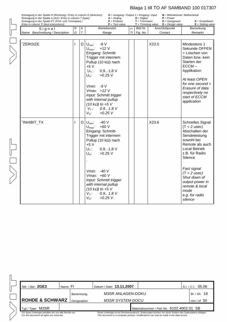
Eintragung in der Spalte R (Richtung) / Entry in column D (direction): O = Ausgang / Output I = Eingang / Input B = Bidirektional / Bidirectional Eintragung in der Spalte A (Art) / Entry in column T (type): A = Analog D = Digital P = Power Eintragung in der Spalte PT (Prüf- und Trimmplan) / P = Prüfwert T = Trimmwert D = Designwert E = Einstellwert Entry in column TI (test instructions): P = Test value T = Trimming value D = Design value E = Setting value
S i g n a l R A Wertebereich PT Bild Nr. Anschlußpunkt Bemerkung Name Beschreibung / Description D T Range TI Fig. No. Contact Remarks
Abt. / Dpt.: 2GE3 Name: Fl Datum / Date: 13.11.2007 Ä.I. / C.I.: 05.06
Benennung: M3SR ANLAGEN-DOKU Bl. / Sh. 18
ROHDE & SCHWARZ Designation: M3SR SYSTEM DOCU von / of 50
Typ / Type: M3SR Materialnummer / Part No.: 6102.4002.01 SB Für diese Unterlage behalten wir uns alle Rechte vor. Diese Unterlage ist ein Rechnerausdruck, Änderungen können nur durch Ändern des Datensatzes erfolgen. For this document all rights are reserved. This document is a computer printout, modifications can only be made in the data record.
˜ZEROIZE I D Umin: -9 V Umax: +12 V Eingang: Schmitt-Trigger mit internem Pullup (10 kW) nach +5 VUT-: 0,9...1,8 V UH: >0.25 V
Vmin: -9 V Vmax: +12 V Input: Schmitt trigger with internal pullup (10 kW) to +5 V VT-: 0.9.. 1.8 V VH: >0.25 V
X23.5 Mindestens 1 Sekunde OFFEN = Löschen von Daten bzw. kein Starten der ECCM – Applikation At least OPEN for one second = Erasure of data respectively no start of ECCM application
˜INHIBIT_TX I D Umin: -40 V Umax: +60 V Eingang: Schmitt-Trigger mit internem Pullup (10 kW) nach +5 V UT-: 0,9...1,8 V UH: >0.25 V
.
Vmin: -40 V Vmax: +60 V Input: Schmitt trigger with internal pullup (10 kW) to +5 V VT-: 0.9.. 1.8 V VH: >0.25 V.
X23.6 Schnelles Signal (T < 2 usec) Abschalten der Sendeleistung sowohl bei Remote als auch Local Betrieb z.B. für Radio Silence
Fast signal (T < 2 usec) Shut down of output power in remote & local mode e.g. for radio silence
Bilaga 1 till TO AF SAMBAND 100 017307
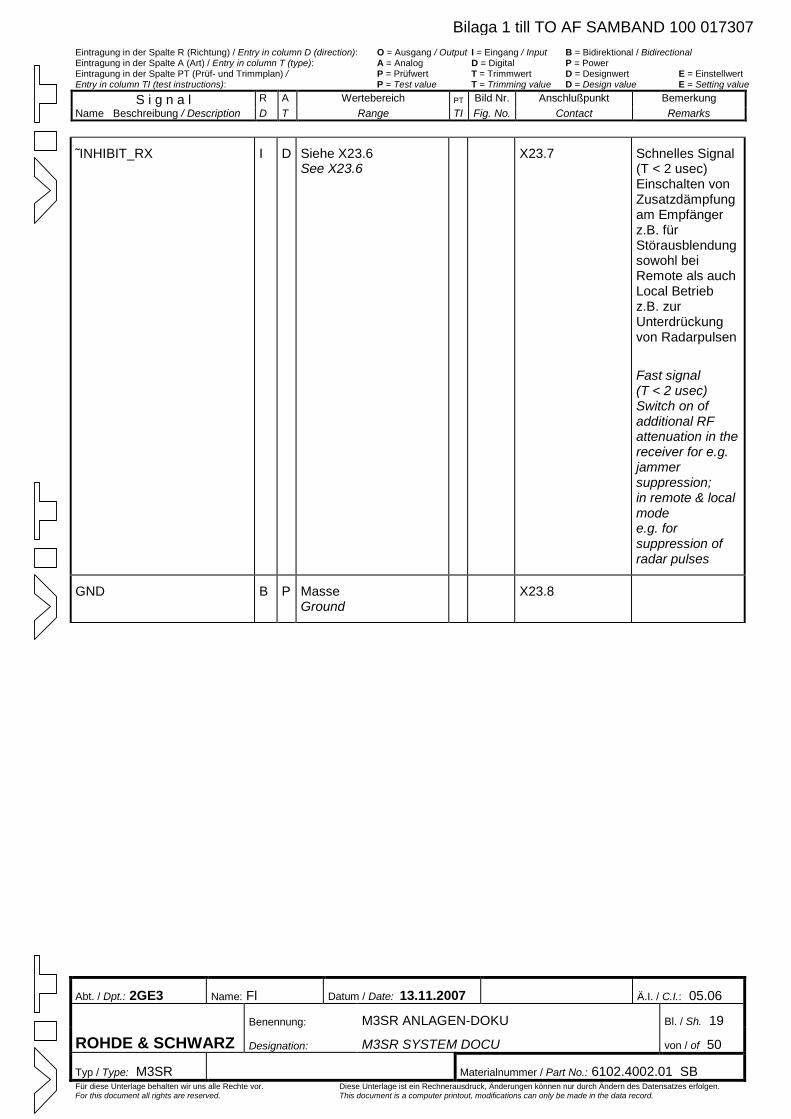
Eintragung in der Spalte R (Richtung) / Entry in column D (direction): O = Ausgang / Output I = Eingang / Input B = Bidirektional / Bidirectional Eintragung in der Spalte A (Art) / Entry in column T (type): A = Analog D = Digital P = Power Eintragung in der Spalte PT (Prüf- und Trimmplan) / P = Prüfwert T = Trimmwert D = Designwert E = Einstellwert Entry in column TI (test instructions): P = Test value T = Trimming value D = Design value E = Setting value
S i g n a l R A Wertebereich PT Bild Nr. Anschlußpunkt Bemerkung Name Beschreibung / Description D T Range TI Fig. No. Contact Remarks
Abt. / Dpt.: 2GE3 Name: Fl Datum / Date: 13.11.2007 Ä.I. / C.I.: 05.06
Benennung: M3SR ANLAGEN-DOKU Bl. / Sh. 19
ROHDE & SCHWARZ Designation: M3SR SYSTEM DOCU von / of 50
Typ / Type: M3SR Materialnummer / Part No.: 6102.4002.01 SB Für diese Unterlage behalten wir uns alle Rechte vor. Diese Unterlage ist ein Rechnerausdruck, Änderungen können nur durch Ändern des Datensatzes erfolgen. For this document all rights are reserved. This document is a computer printout, modifications can only be made in the data record.
˜INHIBIT_RX I D Siehe X23.6 See X23.6
X23.7 Schnelles Signal (T < 2 usec) Einschalten von Zusatzdämpfung am Empfänger z.B. für Störausblendungsowohl bei Remote als auch Local Betrieb z.B. zur Unterdrückung von Radarpulsen
Fast signal (T < 2 usec) Switch on of additional RF attenuation in the receiver for e.g. jammer suppression; in remote & local mode e.g. for suppression of radar pulses
GND B P Masse Ground
X23.8
Bilaga 1 till TO AF SAMBAND 100 017307
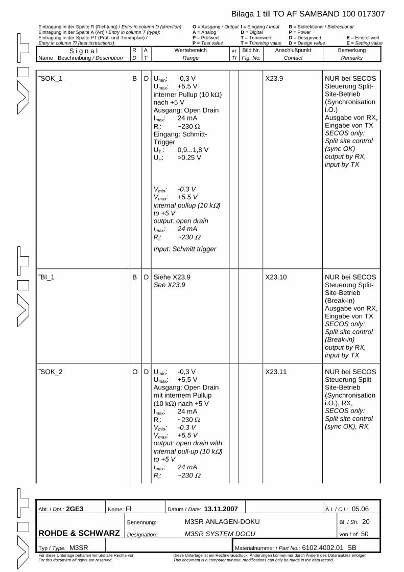
Eintragung in der Spalte R (Richtung) / Entry in column D (direction): O = Ausgang / Output I = Eingang / Input B = Bidirektional / Bidirectional Eintragung in der Spalte A (Art) / Entry in column T (type): A = Analog D = Digital P = Power Eintragung in der Spalte PT (Prüf- und Trimmplan) / P = Prüfwert T = Trimmwert D = Designwert E = Einstellwert Entry in column TI (test instructions): P = Test value T = Trimming value D = Design value E = Setting value
S i g n a l R A Wertebereich PT Bild Nr. Anschlußpunkt Bemerkung Name Beschreibung / Description D T Range TI Fig. No. Contact Remarks
Abt. / Dpt.: 2GE3 Name: Fl Datum / Date: 13.11.2007 Ä.I. / C.I.: 05.06
Benennung: M3SR ANLAGEN-DOKU Bl. / Sh. 20
ROHDE & SCHWARZ Designation: M3SR SYSTEM DOCU von / of 50
Typ / Type: M3SR Materialnummer / Part No.: 6102.4002.01 SB Für diese Unterlage behalten wir uns alle Rechte vor. Diese Unterlage ist ein Rechnerausdruck, Änderungen können nur durch Ändern des Datensatzes erfolgen. For this document all rights are reserved. This document is a computer printout, modifications can only be made in the data record.
˜SOK_1 B D Umin: -0,3 V Umax: +5,5 V interner Pullup (10 kW)nach +5 V Ausgang: Open Drain Imax: 24 mA Ri: ~230 WEingang: Schmitt-Trigger UT-: 0,9...1,8 V UH: >0.25 V
Vmin: -0.3 V Vmax: +5.5 V internal pullup (10 kW)to +5 V output: open drain Imax: 24 mA Ri: ~230 W
Input: Schmitt trigger
X23.9 NUR bei SECOSSteuerung Split-Site-Betrieb (Synchronisation i.O.) Ausgabe von RX, Eingabe von TX SECOS only: Split site control (sync OK) output by RX, input by TX
˜BI_1 B D Siehe X23.9 See X23.9
X23.10 NUR bei SECOS Steuerung Split-Site-Betrieb (Break-in) Ausgabe von RX, Eingabe von TX SECOS only: Split site control (Break-in) output by RX, input by TX
˜SOK_2 O D Umin: -0,3 V Umax: +5,5 V Ausgang: Open Drain mit internem Pullup (10 kW) nach +5 V Imax: 24 mA Ri: ~230 WVmin: -0.3 V Vmax: +5.5 V output: open drain with internal pull-up (10 kW)to +5 V Imax: 24 mA Ri: ~230 W
X23.11 NUR bei SECOS Steuerung Split-Site-Betrieb (Synchronisation i.O.), RX, SECOS only: Split site control (sync OK), RX,
Bilaga 1 till TO AF SAMBAND 100 017307
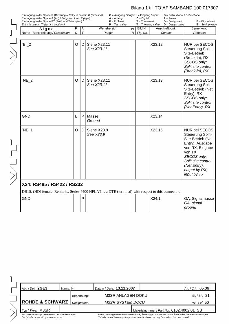
Eintragung in der Spalte R (Richtung) / Entry in column D (direction): O = Ausgang / Output I = Eingang / Input B = Bidirektional / Bidirectional Eintragung in der Spalte A (Art) / Entry in column T (type): A = Analog D = Digital P = Power Eintragung in der Spalte PT (Prüf- und Trimmplan) / P = Prüfwert T = Trimmwert D = Designwert E = Einstellwert Entry in column TI (test instructions): P = Test value T = Trimming value D = Design value E = Setting value
S i g n a l R A Wertebereich PT Bild Nr. Anschlußpunkt Bemerkung Name Beschreibung / Description D T Range TI Fig. No. Contact Remarks
Abt. / Dpt.: 2GE3 Name: Fl Datum / Date: 13.11.2007 Ä.I. / C.I.: 05.06
Benennung: M3SR ANLAGEN-DOKU Bl. / Sh. 21
ROHDE & SCHWARZ Designation: M3SR SYSTEM DOCU von / of 50
Typ / Type: M3SR Materialnummer / Part No.: 6102.4002.01 SB Für diese Unterlage behalten wir uns alle Rechte vor. Diese Unterlage ist ein Rechnerausdruck, Änderungen können nur durch Ändern des Datensatzes erfolgen. For this document all rights are reserved. This document is a computer printout, modifications can only be made in the data record.
˜BI_2 O D Siehe X23.11 See X23.11
X23.12 NUR bei SECOS Steuerung Split-Site-Betrieb (Break-in), RX SECOS only: Split site control (Break-in), RX
˜NE_2 O D Siehe X23.11 See X23.11
X23.13 NUR bei SECOS Steuerung Split-Site-Betrieb (Net Entry), RX SECOS only: Split site control (Net Entry), RX
GND B P Masse Ground
X23.14
˜NE_1 O D Siehe X23.9 See X23.9
X23.15 NUR bei SECOS Steuerung Split-Site-Betrieb (Net Entry), Ausgabe von RX, Eingabe von TX SECOS only: Split site control (Net Entry), output by RX, input by TX
X24: RS485 / RS422 / RS232 DB15, (HD) female Remarks. Series 4400 HPLAT is a DTE (terminal) with respect to this connector.
GND P X24.1 GA, SignalmasseGA, signal ground
Bilaga 1 till TO AF SAMBAND 100 017307
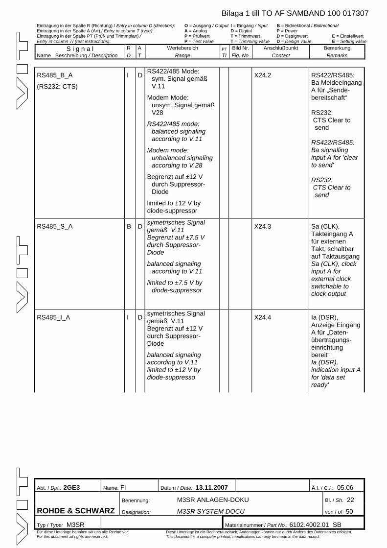
Eintragung in der Spalte R (Richtung) / Entry in column D (direction): O = Ausgang / Output I = Eingang / Input B = Bidirektional / Bidirectional Eintragung in der Spalte A (Art) / Entry in column T (type): A = Analog D = Digital P = Power Eintragung in der Spalte PT (Prüf- und Trimmplan) / P = Prüfwert T = Trimmwert D = Designwert E = Einstellwert Entry in column TI (test instructions): P = Test value T = Trimming value D = Design value E = Setting value
S i g n a l R A Wertebereich PT Bild Nr. Anschlußpunkt Bemerkung Name Beschreibung / Description D T Range TI Fig. No. Contact Remarks
Abt. / Dpt.: 2GE3 Name: Fl Datum / Date: 13.11.2007 Ä.I. / C.I.: 05.06
Benennung: M3SR ANLAGEN-DOKU Bl. / Sh. 22
ROHDE & SCHWARZ Designation: M3SR SYSTEM DOCU von / of 50
Typ / Type: M3SR Materialnummer / Part No.: 6102.4002.01 SB Für diese Unterlage behalten wir uns alle Rechte vor. Diese Unterlage ist ein Rechnerausdruck, Änderungen können nur durch Ändern des Datensatzes erfolgen. For this document all rights are reserved. This document is a computer printout, modifications can only be made in the data record.
RS485_B_A
(RS232: CTS)
I D RS422/485 Mode: sym. Signal gemäß V.11
Modem Mode: unsym, Signal gemäß V28
RS422/485 mode: balanced signaling according to V.11
Modem mode: unbalanced signaling according to V.28
Begrenzt auf ±12 V durch Suppressor-Diode
limited to ±12 V by diode-suppressor
X24.2 RS422/RS485: Ba Meldeeingang A für „Sende-bereitschaft“ RS232: CTS Clear to send RS422/RS485: Ba signalling input A for 'clear to send' RS232: CTS Clear to send
RS485_S_A B D symetrisches Signal gemäß V.11 Begrenzt auf ±7.5 V durch Suppressor-Diode
balanced signaling according to V.11
limited to ±7.5 V by diode-suppressor
X24.3 Sa (CLK), Takteingang A für externen Takt, schaltbar auf Taktausgang Sa (CLK), clock input A for external clock switchable to clock output
RS485_I_A I D symetrisches Signal gemäß V.11 Begrenzt auf ±12 V durch Suppressor-Diode
balanced signaling according to V.11 limited to ±12 V by diode-suppresso
X24.4 Ia (DSR), Anzeige Eingang A für „Daten-übertragungs-einrichtung bereit“ Ia (DSR), indication input A for 'data set ready'
Bilaga 1 till TO AF SAMBAND 100 017307
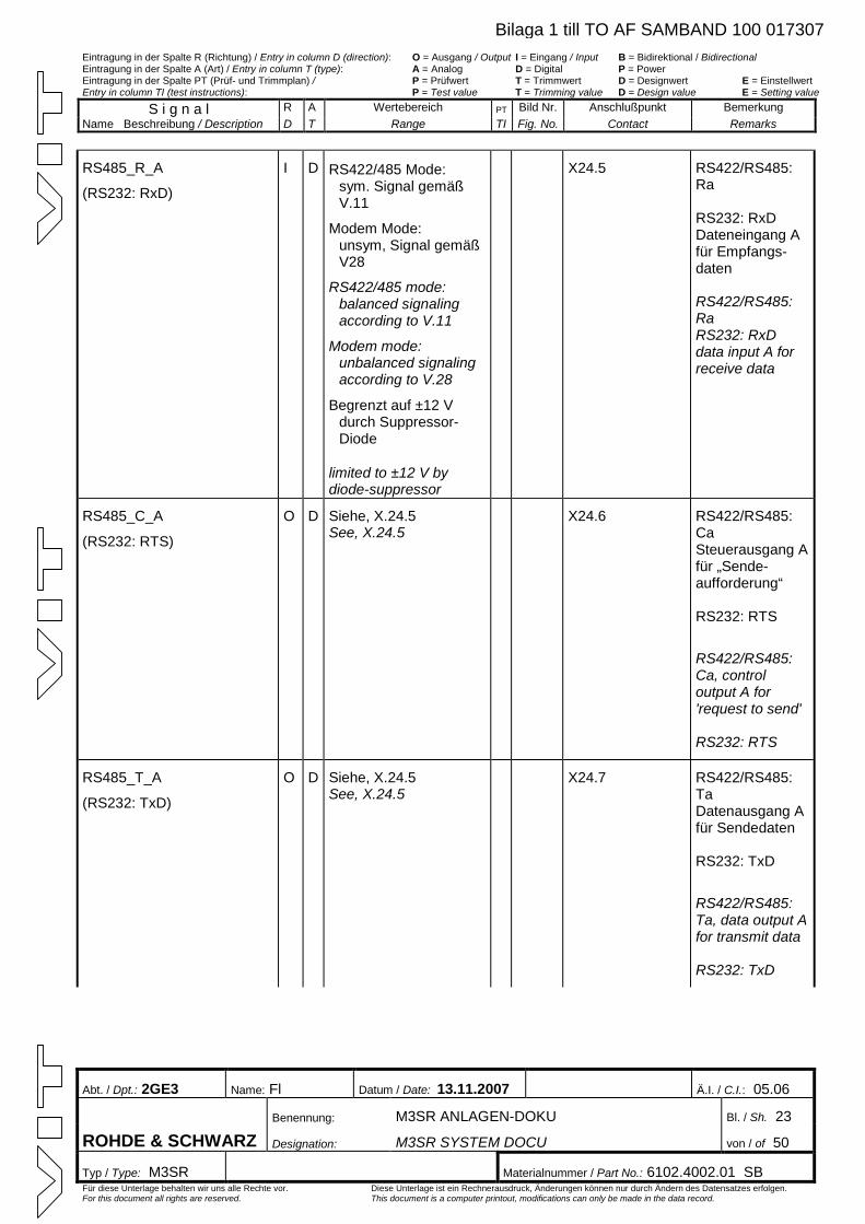
Eintragung in der Spalte R (Richtung) / Entry in column D (direction): O = Ausgang / Output I = Eingang / Input B = Bidirektional / Bidirectional Eintragung in der Spalte A (Art) / Entry in column T (type): A = Analog D = Digital P = Power Eintragung in der Spalte PT (Prüf- und Trimmplan) / P = Prüfwert T = Trimmwert D = Designwert E = Einstellwert Entry in column TI (test instructions): P = Test value T = Trimming value D = Design value E = Setting value
S i g n a l R A Wertebereich PT Bild Nr. Anschlußpunkt Bemerkung Name Beschreibung / Description D T Range TI Fig. No. Contact Remarks
Abt. / Dpt.: 2GE3 Name: Fl Datum / Date: 13.11.2007 Ä.I. / C.I.: 05.06
Benennung: M3SR ANLAGEN-DOKU Bl. / Sh. 23
ROHDE & SCHWARZ Designation: M3SR SYSTEM DOCU von / of 50
Typ / Type: M3SR Materialnummer / Part No.: 6102.4002.01 SB Für diese Unterlage behalten wir uns alle Rechte vor. Diese Unterlage ist ein Rechnerausdruck, Änderungen können nur durch Ändern des Datensatzes erfolgen. For this document all rights are reserved. This document is a computer printout, modifications can only be made in the data record.
RS485_R_A
(RS232: RxD)
I D RS422/485 Mode: sym. Signal gemäß V.11
Modem Mode: unsym, Signal gemäß V28
RS422/485 mode: balanced signaling according to V.11
Modem mode: unbalanced signaling according to V.28
Begrenzt auf ±12 V durch Suppressor-Diode
limited to ±12 V by diode-suppressor
X24.5 RS422/RS485: Ra RS232: RxD Dateneingang A für Empfangs-daten RS422/RS485: Ra RS232: RxD data input A for receive data
RS485_C_A
(RS232: RTS)
O D Siehe, X.24.5 See, X.24.5
X24.6 RS422/RS485: Ca Steuerausgang A für „Sende-aufforderung“ RS232: RTS
RS422/RS485: Ca, control output A for 'request to send'
RS232: RTS
RS485_T_A
(RS232: TxD)
O D Siehe, X.24.5 See, X.24.5
X24.7 RS422/RS485: Ta Datenausgang A für Sendedaten RS232: TxD
RS422/RS485: Ta, data output A for transmit data
RS232: TxD
Bilaga 1 till TO AF SAMBAND 100 017307
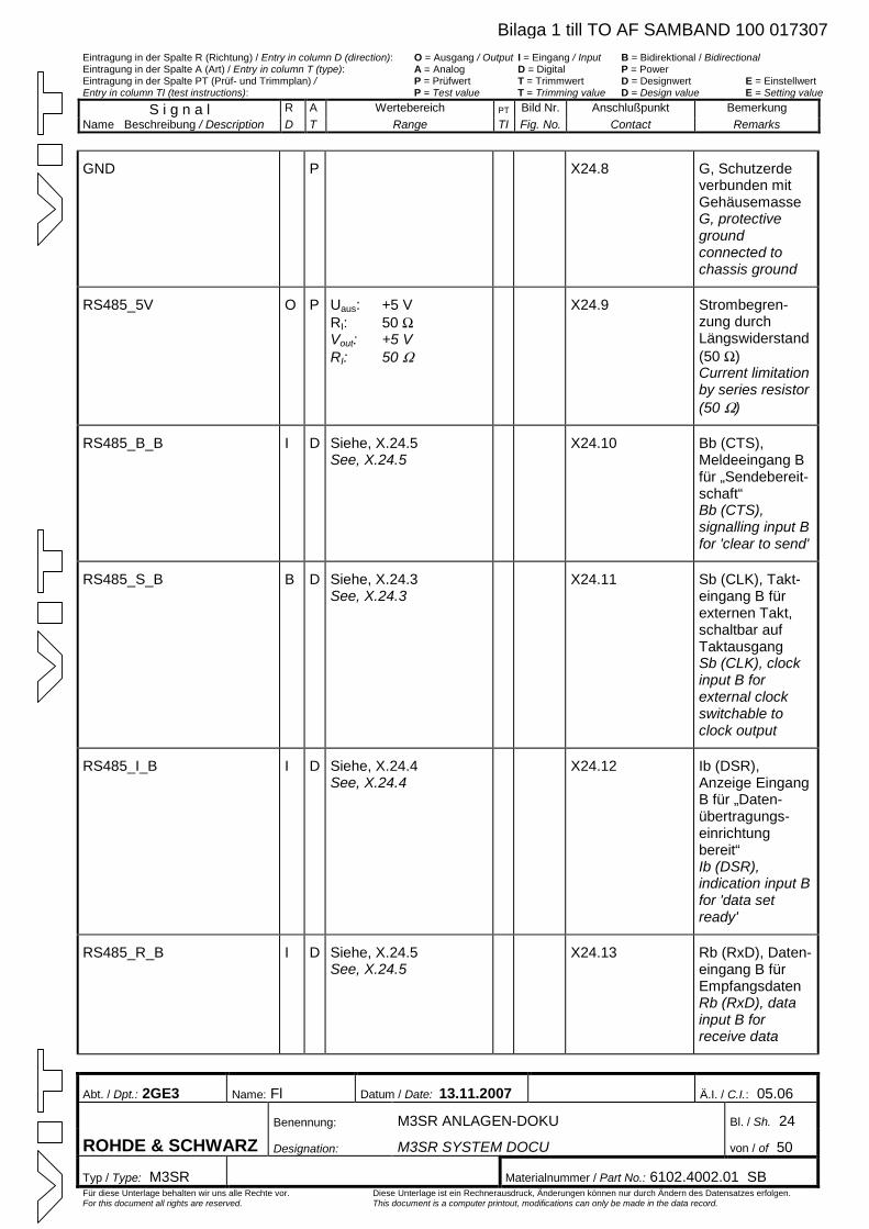
Eintragung in der Spalte R (Richtung) / Entry in column D (direction): O = Ausgang / Output I = Eingang / Input B = Bidirektional / Bidirectional Eintragung in der Spalte A (Art) / Entry in column T (type): A = Analog D = Digital P = Power Eintragung in der Spalte PT (Prüf- und Trimmplan) / P = Prüfwert T = Trimmwert D = Designwert E = Einstellwert Entry in column TI (test instructions): P = Test value T = Trimming value D = Design value E = Setting value
S i g n a l R A Wertebereich PT Bild Nr. Anschlußpunkt Bemerkung Name Beschreibung / Description D T Range TI Fig. No. Contact Remarks
Abt. / Dpt.: 2GE3 Name: Fl Datum / Date: 13.11.2007 Ä.I. / C.I.: 05.06
Benennung: M3SR ANLAGEN-DOKU Bl. / Sh. 24
ROHDE & SCHWARZ Designation: M3SR SYSTEM DOCU von / of 50
Typ / Type: M3SR Materialnummer / Part No.: 6102.4002.01 SB Für diese Unterlage behalten wir uns alle Rechte vor. Diese Unterlage ist ein Rechnerausdruck, Änderungen können nur durch Ändern des Datensatzes erfolgen. For this document all rights are reserved. This document is a computer printout, modifications can only be made in the data record.
GND P X24.8 G, Schutzerde verbunden mit Gehäusemasse G, protective ground connected to chassis ground
RS485_5V O P Uaus: +5 V RI: 50 WVout: +5 V RI: 50 W
X24.9 Strombegren-zung durch Längswiderstand (50 W)Current limitation by series resistor (50 W)
RS485_B_B I D Siehe, X.24.5 See, X.24.5
X24.10 Bb (CTS), Meldeeingang B für „Sendebereit-schaft“ Bb (CTS), signalling input B for 'clear to send'
RS485_S_B B D Siehe, X.24.3 See, X.24.3
X24.11 Sb (CLK), Takt-eingang B für externen Takt, schaltbar auf Taktausgang Sb (CLK), clock input B for external clock switchable to clock output
RS485_I_B I D Siehe, X.24.4 See, X.24.4
X24.12 Ib (DSR), Anzeige Eingang B für „Daten-übertragungs-einrichtung bereit“ Ib (DSR), indication input B for 'data set ready'
RS485_R_B I D Siehe, X.24.5 See, X.24.5
X24.13 Rb (RxD), Daten-eingang B für Empfangsdaten Rb (RxD), data input B for receive data
Bilaga 1 till TO AF SAMBAND 100 017307
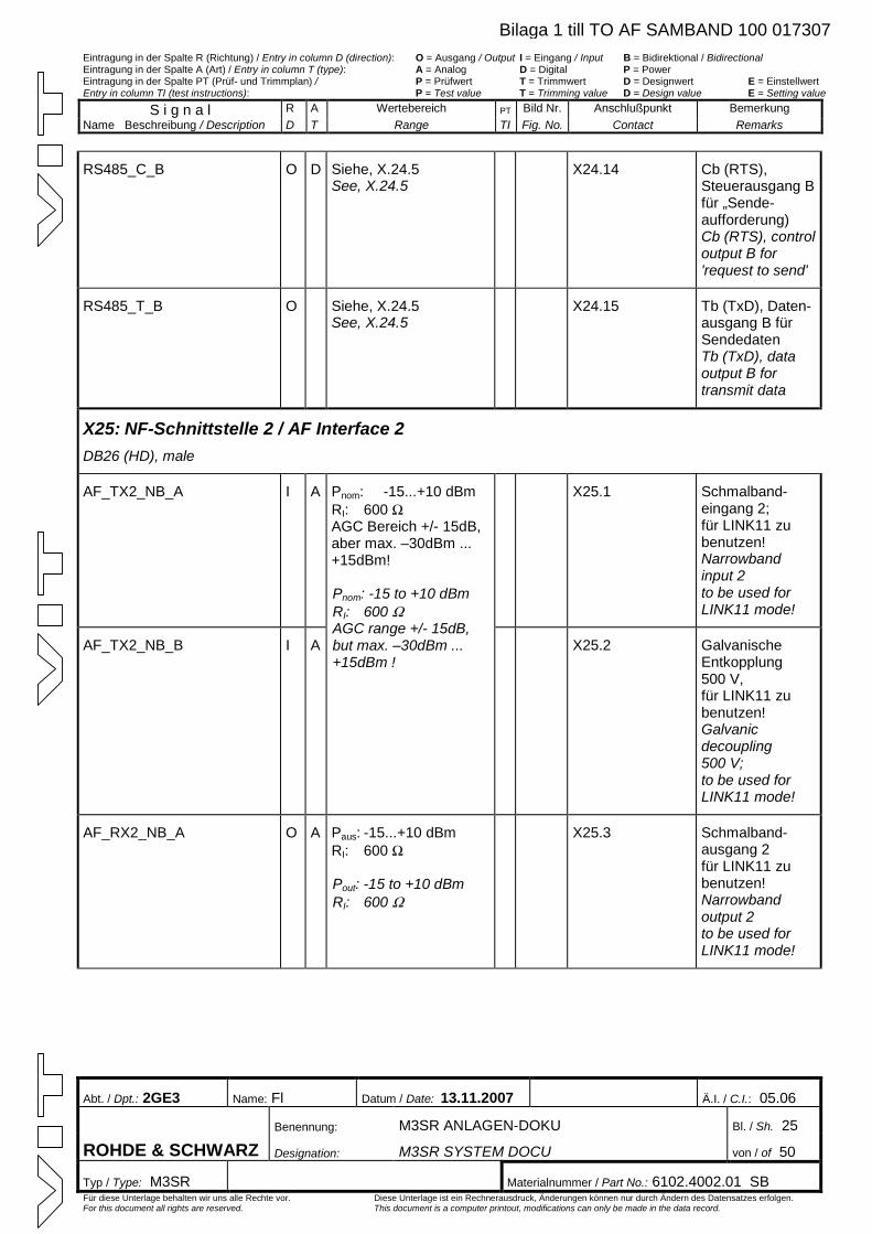
Eintragung in der Spalte R (Richtung) / Entry in column D (direction): O = Ausgang / Output I = Eingang / Input B = Bidirektional / Bidirectional Eintragung in der Spalte A (Art) / Entry in column T (type): A = Analog D = Digital P = Power Eintragung in der Spalte PT (Prüf- und Trimmplan) / P = Prüfwert T = Trimmwert D = Designwert E = Einstellwert Entry in column TI (test instructions): P = Test value T = Trimming value D = Design value E = Setting value
S i g n a l R A Wertebereich PT Bild Nr. Anschlußpunkt Bemerkung Name Beschreibung / Description D T Range TI Fig. No. Contact Remarks
Abt. / Dpt.: 2GE3 Name: Fl Datum / Date: 13.11.2007 Ä.I. / C.I.: 05.06
Benennung: M3SR ANLAGEN-DOKU Bl. / Sh. 25
ROHDE & SCHWARZ Designation: M3SR SYSTEM DOCU von / of 50
Typ / Type: M3SR Materialnummer / Part No.: 6102.4002.01 SB Für diese Unterlage behalten wir uns alle Rechte vor. Diese Unterlage ist ein Rechnerausdruck, Änderungen können nur durch Ändern des Datensatzes erfolgen. For this document all rights are reserved. This document is a computer printout, modifications can only be made in the data record.
RS485_C_B O D Siehe, X.24.5 See, X.24.5
X24.14 Cb (RTS), Steuerausgang B für „Sende-aufforderung) Cb (RTS), control output B for 'request to send'
RS485_T_B O Siehe, X.24.5 See, X.24.5
X24.15 Tb (TxD), Daten-ausgang B für Sendedaten Tb (TxD), data output B for transmit data
X25: NF-Schnittstelle 2 / AF Interface 2 DB26 (HD), male
AF_TX2_NB_A I A X25.1 Schmalband-eingang 2; für LINK11 zu benutzen! Narrowband input 2 to be used for LINK11 mode!
AF_TX2_NB_B I A
Pnom: -15...+10 dBm RI: 600 WAGC Bereich +/- 15dB, aber max. –30dBm ... +15dBm! Pnom: -15 to +10 dBm RI: 600 WAGC range +/- 15dB, but max. –30dBm ... +15dBm !
X25.2 Galvanische Entkopplung 500 V, für LINK11 zu benutzen! Galvanic decoupling 500 V; to be used for LINK11 mode!
AF_RX2_NB_A O A Paus: -15...+10 dBm RI: 600 W
Pout: -15 to +10 dBm RI: 600 W
X25.3 Schmalband-ausgang 2 für LINK11 zu benutzen! Narrowband output 2 to be used for LINK11 mode!
Bilaga 1 till TO AF SAMBAND 100 017307
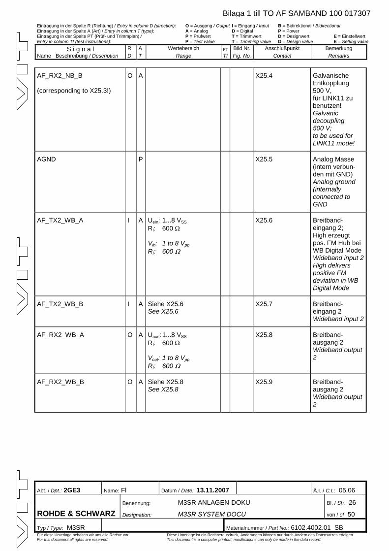
Eintragung in der Spalte R (Richtung) / Entry in column D (direction): O = Ausgang / Output I = Eingang / Input B = Bidirektional / Bidirectional Eintragung in der Spalte A (Art) / Entry in column T (type): A = Analog D = Digital P = Power Eintragung in der Spalte PT (Prüf- und Trimmplan) / P = Prüfwert T = Trimmwert D = Designwert E = Einstellwert Entry in column TI (test instructions): P = Test value T = Trimming value D = Design value E = Setting value
S i g n a l R A Wertebereich PT Bild Nr. Anschlußpunkt Bemerkung Name Beschreibung / Description D T Range TI Fig. No. Contact Remarks
Abt. / Dpt.: 2GE3 Name: Fl Datum / Date: 13.11.2007 Ä.I. / C.I.: 05.06
Benennung: M3SR ANLAGEN-DOKU Bl. / Sh. 26
ROHDE & SCHWARZ Designation: M3SR SYSTEM DOCU von / of 50
Typ / Type: M3SR Materialnummer / Part No.: 6102.4002.01 SB Für diese Unterlage behalten wir uns alle Rechte vor. Diese Unterlage ist ein Rechnerausdruck, Änderungen können nur durch Ändern des Datensatzes erfolgen. For this document all rights are reserved. This document is a computer printout, modifications can only be made in the data record.
AF_RX2_NB_B (corresponding to X25.3!)
O A X25.4 Galvanische Entkopplung 500 V, für LINK11 zu benutzen! Galvanic decoupling 500 V; to be used for LINK11 mode!
AGND P X25.5 Analog Masse (intern verbun-den mit GND) Analog ground (internally connected to GND
AF_TX2_WB_A I A Uein: 1...8 VSS
RI: 600 W
Vin: 1 to 8 Vpp
RI: 600 W
X25.6 Breitband-eingang 2; High erzeugt pos. FM Hub bei WB Digital Mode Wideband input 2High delivers positive FM deviation in WB Digital Mode
AF_TX2_WB_B I A Siehe X25.6 See X25.6
X25.7 Breitband-eingang 2 Wideband input 2
AF_RX2_WB_A O A Uaus: 1...8 VSS
RI: 600 W
Vout: 1 to 8 Vpp
RI: 600 W
X25.8 Breitband-ausgang 2 Wideband output 2
AF_RX2_WB_B O A Siehe X25.8 See X25.8
X25.9 Breitband-ausgang 2 Wideband output 2
Bilaga 1 till TO AF SAMBAND 100 017307
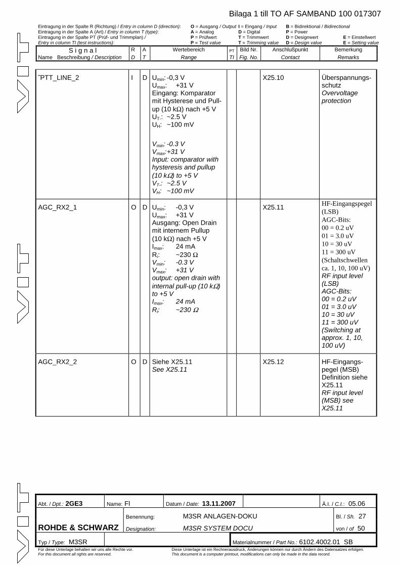
Eintragung in der Spalte R (Richtung) / Entry in column D (direction): O = Ausgang / Output I = Eingang / Input B = Bidirektional / Bidirectional Eintragung in der Spalte A (Art) / Entry in column T (type): A = Analog D = Digital P = Power Eintragung in der Spalte PT (Prüf- und Trimmplan) / P = Prüfwert T = Trimmwert D = Designwert E = Einstellwert Entry in column TI (test instructions): P = Test value T = Trimming value D = Design value E = Setting value
S i g n a l R A Wertebereich PT Bild Nr. Anschlußpunkt Bemerkung Name Beschreibung / Description D T Range TI Fig. No. Contact Remarks
Abt. / Dpt.: 2GE3 Name: Fl Datum / Date: 13.11.2007 Ä.I. / C.I.: 05.06
Benennung: M3SR ANLAGEN-DOKU Bl. / Sh. 27
ROHDE & SCHWARZ Designation: M3SR SYSTEM DOCU von / of 50
Typ / Type: M3SR Materialnummer / Part No.: 6102.4002.01 SB Für diese Unterlage behalten wir uns alle Rechte vor. Diese Unterlage ist ein Rechnerausdruck, Änderungen können nur durch Ändern des Datensatzes erfolgen. For this document all rights are reserved. This document is a computer printout, modifications can only be made in the data record.
˜PTT_LINE_2 I D Umin: -0,3 V Umax: +31 V Eingang: Komparator mit Hysterese und Pull-up (10 kW) nach +5 V UT-: ~2.5 V UH: ~100 mV
Vmin: -0.3 V Vmax:+31 V Input: comparator with hysteresis and pullup (10 kW) to +5 V VT-: ~2.5 V VH: ~100 mV
X25.10 Überspannungs-schutz Overvoltage protection
AGC_RX2_1 O D Umin: -0,3 V Umax: +31 V Ausgang: Open Drain mit internem Pullup (10 kW) nach +5 V Imax: 24 mA Ri: ~230 WVmin: -0.3 V Vmax: +31 V output: open drain with internal pull-up (10 kW)to +5 V Imax: 24 mA Ri: ~230 W
X25.11 HF-Eingangspegel (LSB) AGC-Bits: 00 = 0.2 uV 01 = 3.0 uV 10 = 30 uV 11 = 300 uV (Schaltschwellen ca. 1, 10, 100 uV) RF input level (LSB) AGC-Bits: 00 = 0.2 uV 01 = 3.0 uV 10 = 30 uV 11 = 300 uV (Swítching at approx. 1, 10, 100 uV)
AGC_RX2_2 O D Siehe X25.11 See X25.11
X25.12 HF-Eingangs-pegel (MSB) Definition siehe X25.11 RF input level (MSB) see X25.11
Bilaga 1 till TO AF SAMBAND 100 017307
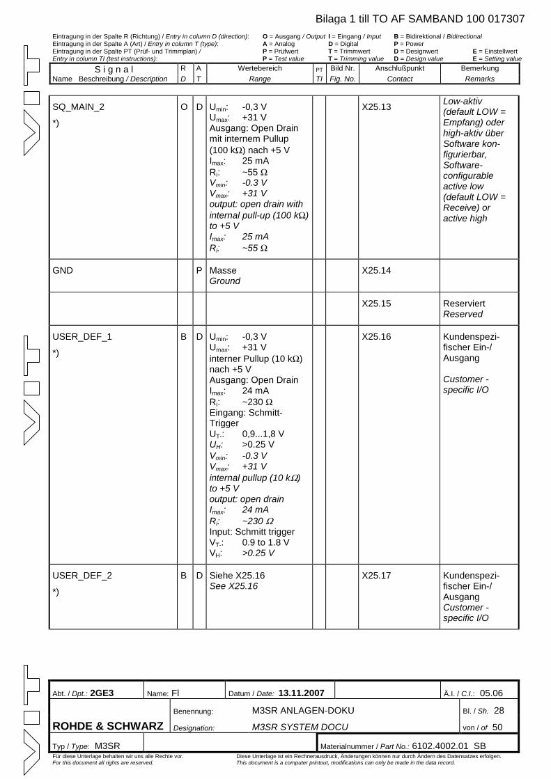
Eintragung in der Spalte R (Richtung) / Entry in column D (direction): O = Ausgang / Output I = Eingang / Input B = Bidirektional / Bidirectional Eintragung in der Spalte A (Art) / Entry in column T (type): A = Analog D = Digital P = Power Eintragung in der Spalte PT (Prüf- und Trimmplan) / P = Prüfwert T = Trimmwert D = Designwert E = Einstellwert Entry in column TI (test instructions): P = Test value T = Trimming value D = Design value E = Setting value
S i g n a l R A Wertebereich PT Bild Nr. Anschlußpunkt Bemerkung Name Beschreibung / Description D T Range TI Fig. No. Contact Remarks
Abt. / Dpt.: 2GE3 Name: Fl Datum / Date: 13.11.2007 Ä.I. / C.I.: 05.06
Benennung: M3SR ANLAGEN-DOKU Bl. / Sh. 28
ROHDE & SCHWARZ Designation: M3SR SYSTEM DOCU von / of 50
Typ / Type: M3SR Materialnummer / Part No.: 6102.4002.01 SB Für diese Unterlage behalten wir uns alle Rechte vor. Diese Unterlage ist ein Rechnerausdruck, Änderungen können nur durch Ändern des Datensatzes erfolgen. For this document all rights are reserved. This document is a computer printout, modifications can only be made in the data record.
SQ_MAIN_2
*)
O D Umin: -0,3 V Umax: +31 V Ausgang: Open Drain mit internem Pullup (100 kW) nach +5 V Imax: 25 mA Ri: ~55 WVmin: -0.3 V Vmax: +31 V output: open drain with internal pull-up (100 kW)to +5 V Imax: 25 mA Ri: ~55 W
X25.13 Low-aktiv (default LOW = Empfang) oder high-aktiv über Software kon-figurierbar, Software-configurable active low (default LOW = Receive) or active high
GND P Masse Ground
X25.14
X25.15 Reserviert Reserved
Umin: -0,3 V Umax: +31 V interner Pullup (10 kW)nach +5 V Ausgang: Open Drain Imax: 24 mA Ri: ~230 WEingang: Schmitt-Trigger UT-: 0,9...1,8 V UH: >0.25 V
X25.16 Kundenspezi-fischer Ein-/ Ausgang Customer -specific I/O
USER_DEF_1
*)
B D
Vmin: -0.3 V Vmax: +31 V internal pullup (10 kW)to +5 V output: open drain Imax: 24 mA Ri: ~230 WInput: Schmitt trigger VT-: 0.9 to 1.8 V VH: >0.25 V
USER_DEF_2
*)
B D Siehe X25.16 See X25.16
X25.17 Kundenspezi-fischer Ein-/ Ausgang Customer -specific I/O
Bilaga 1 till TO AF SAMBAND 100 017307
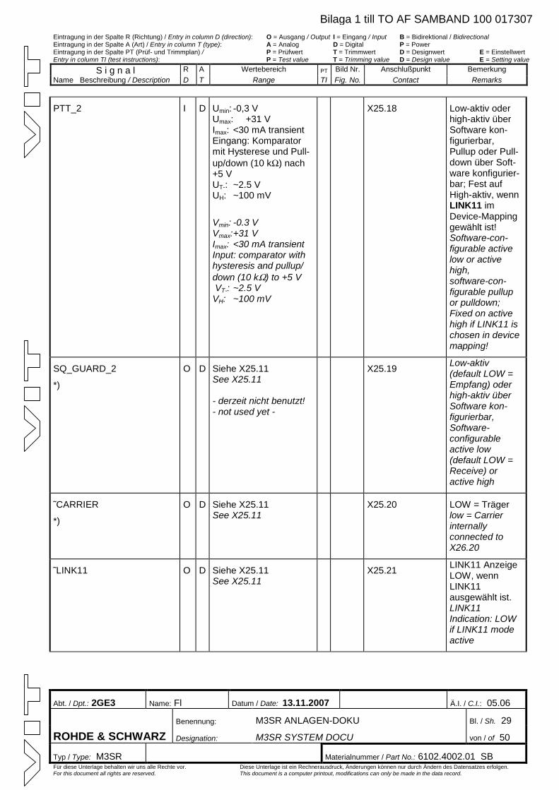
Eintragung in der Spalte R (Richtung) / Entry in column D (direction): O = Ausgang / Output I = Eingang / Input B = Bidirektional / Bidirectional Eintragung in der Spalte A (Art) / Entry in column T (type): A = Analog D = Digital P = Power Eintragung in der Spalte PT (Prüf- und Trimmplan) / P = Prüfwert T = Trimmwert D = Designwert E = Einstellwert Entry in column TI (test instructions): P = Test value T = Trimming value D = Design value E = Setting value
S i g n a l R A Wertebereich PT Bild Nr. Anschlußpunkt Bemerkung Name Beschreibung / Description D T Range TI Fig. No. Contact Remarks
Abt. / Dpt.: 2GE3 Name: Fl Datum / Date: 13.11.2007 Ä.I. / C.I.: 05.06
Benennung: M3SR ANLAGEN-DOKU Bl. / Sh. 29
ROHDE & SCHWARZ Designation: M3SR SYSTEM DOCU von / of 50
Typ / Type: M3SR Materialnummer / Part No.: 6102.4002.01 SB Für diese Unterlage behalten wir uns alle Rechte vor. Diese Unterlage ist ein Rechnerausdruck, Änderungen können nur durch Ändern des Datensatzes erfolgen. For this document all rights are reserved. This document is a computer printout, modifications can only be made in the data record.
PTT_2 I D Umin: -0,3 V Umax: +31 V Imax: <30 mA transient Eingang: Komparator mit Hysterese und Pull-up/down (10 kW) nach +5 V UT-: ~2.5 V UH: ~100 mV
Vmin: -0.3 V Vmax:+31 V Imax: <30 mA transient Input: comparator with hysteresis and pullup/ down (10 kW) to +5 V VT-: ~2.5 V VH: ~100 mV
X25.18 Low-aktiv oder high-aktiv über Software kon-figurierbar, Pullup oder Pull-down über Soft-ware konfigurier-bar; Fest auf High-aktiv, wenn LINK11 im Device-Mapping gewählt ist! Software-con-figurable active low or active high, software-con-figurable pullup or pulldown; Fixed on active high if LINK11 is chosen in device mapping!
SQ_GUARD_2
*)
O D Siehe X25.11 See X25.11 - derzeit nicht benutzt! - not used yet -
X25.19 Low-aktiv (default LOW = Empfang) oder high-aktiv über Software kon-figurierbar, Software-configurable active low (default LOW = Receive) or active high
˜CARRIER
*)
O D Siehe X25.11 See X25.11
X25.20 LOW = Träger low = Carrier internally connected to X26.20
˜LINK11 O D Siehe X25.11 See X25.11
X25.21 LINK11 AnzeigeLOW, wenn LINK11 ausgewählt ist. LINK11 Indication: LOW if LINK11 mode active
Bilaga 1 till TO AF SAMBAND 100 017307
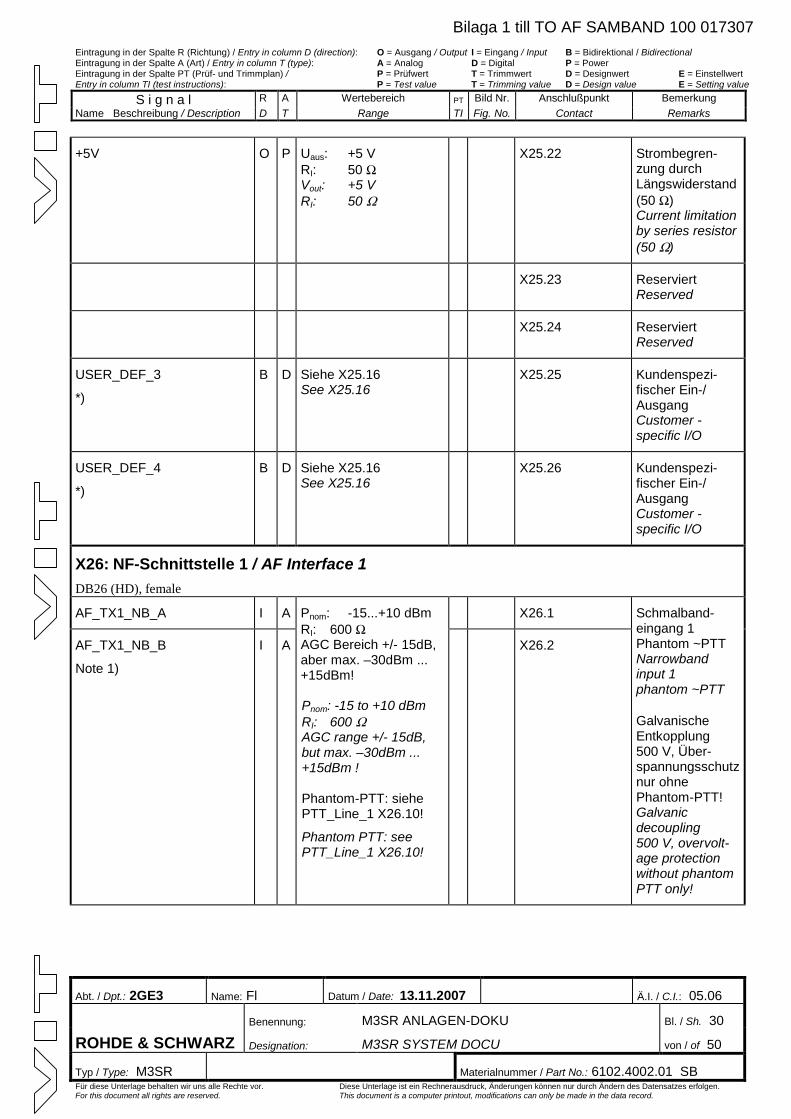
Eintragung in der Spalte R (Richtung) / Entry in column D (direction): O = Ausgang / Output I = Eingang / Input B = Bidirektional / Bidirectional Eintragung in der Spalte A (Art) / Entry in column T (type): A = Analog D = Digital P = Power Eintragung in der Spalte PT (Prüf- und Trimmplan) / P = Prüfwert T = Trimmwert D = Designwert E = Einstellwert Entry in column TI (test instructions): P = Test value T = Trimming value D = Design value E = Setting value
S i g n a l R A Wertebereich PT Bild Nr. Anschlußpunkt Bemerkung Name Beschreibung / Description D T Range TI Fig. No. Contact Remarks
Abt. / Dpt.: 2GE3 Name: Fl Datum / Date: 13.11.2007 Ä.I. / C.I.: 05.06
Benennung: M3SR ANLAGEN-DOKU Bl. / Sh. 30
ROHDE & SCHWARZ Designation: M3SR SYSTEM DOCU von / of 50
Typ / Type: M3SR Materialnummer / Part No.: 6102.4002.01 SB Für diese Unterlage behalten wir uns alle Rechte vor. Diese Unterlage ist ein Rechnerausdruck, Änderungen können nur durch Ändern des Datensatzes erfolgen. For this document all rights are reserved. This document is a computer printout, modifications can only be made in the data record.
+5V O P Uaus: +5 V RI: 50 WVout: +5 V RI: 50 W
X25.22 Strombegren-zung durch Längswiderstand (50 W)Current limitation by series resistor (50 W)
X25.23 Reserviert Reserved
X25.24 Reserviert Reserved
USER_DEF_3
*)
B D Siehe X25.16 See X25.16
X25.25 Kundenspezi-fischer Ein-/ Ausgang Customer -specific I/O
USER_DEF_4
*)
B D Siehe X25.16 See X25.16
X25.26 Kundenspezi-fischer Ein-/ Ausgang Customer -specific I/O
X26: NF-Schnittstelle 1 / AF Interface 1 DB26 (HD), female
AF_TX1_NB_A I A X26.1
AF_TX1_NB_B
Note 1)
I A
Pnom: -15...+10 dBm RI: 600 WAGC Bereich +/- 15dB, aber max. –30dBm ... +15dBm! Pnom: -15 to +10 dBm RI: 600 WAGC range +/- 15dB, but max. –30dBm ... +15dBm ! Phantom-PTT: siehe PTT_Line_1 X26.10!
Phantom PTT: see PTT_Line_1 X26.10!
X26.2
Schmalband-eingang 1 Phantom ~PTT Narrowband input 1 phantom ~PTT
Galvanische Entkopplung 500 V, Über-spannungsschutz nur ohne Phantom-PTT! Galvanic decoupling 500 V, overvolt-age protection without phantom PTT only!
Bilaga 1 till TO AF SAMBAND 100 017307
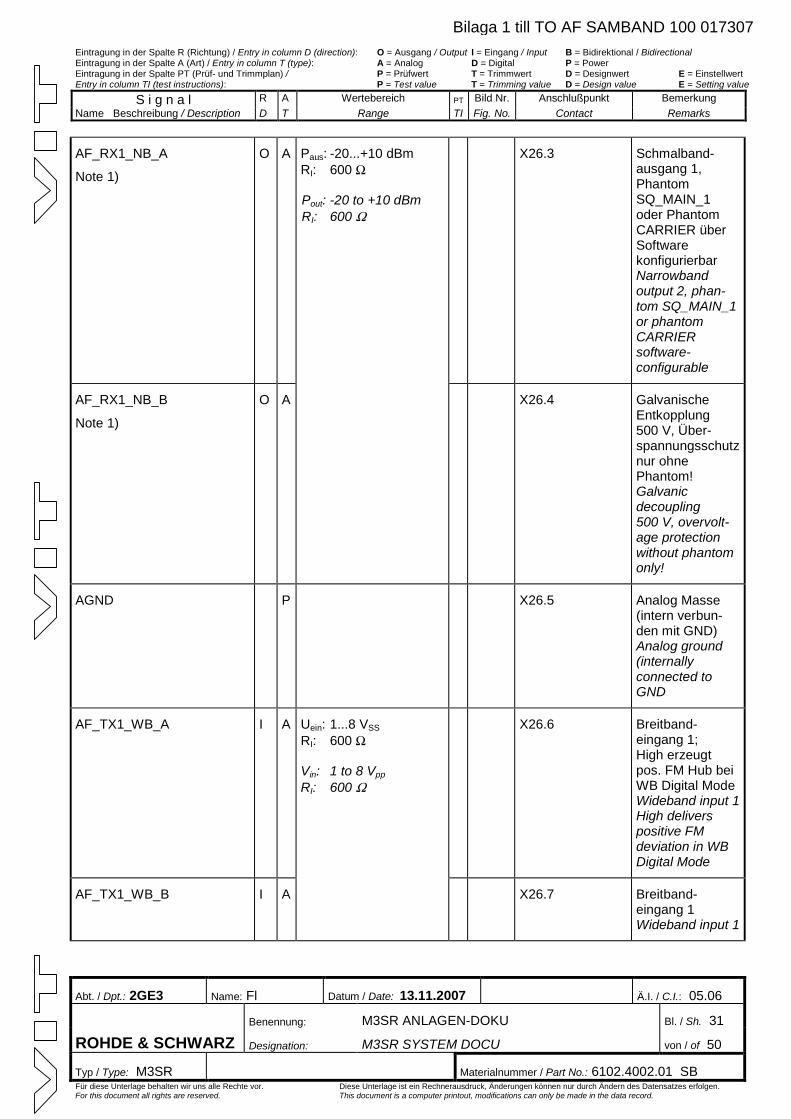
Eintragung in der Spalte R (Richtung) / Entry in column D (direction): O = Ausgang / Output I = Eingang / Input B = Bidirektional / Bidirectional Eintragung in der Spalte A (Art) / Entry in column T (type): A = Analog D = Digital P = Power Eintragung in der Spalte PT (Prüf- und Trimmplan) / P = Prüfwert T = Trimmwert D = Designwert E = Einstellwert Entry in column TI (test instructions): P = Test value T = Trimming value D = Design value E = Setting value
S i g n a l R A Wertebereich PT Bild Nr. Anschlußpunkt Bemerkung Name Beschreibung / Description D T Range TI Fig. No. Contact Remarks
Abt. / Dpt.: 2GE3 Name: Fl Datum / Date: 13.11.2007 Ä.I. / C.I.: 05.06
Benennung: M3SR ANLAGEN-DOKU Bl. / Sh. 31
ROHDE & SCHWARZ Designation: M3SR SYSTEM DOCU von / of 50
Typ / Type: M3SR Materialnummer / Part No.: 6102.4002.01 SB Für diese Unterlage behalten wir uns alle Rechte vor. Diese Unterlage ist ein Rechnerausdruck, Änderungen können nur durch Ändern des Datensatzes erfolgen. For this document all rights are reserved. This document is a computer printout, modifications can only be made in the data record.
AF_RX1_NB_A
Note 1)
O A X26.3 Schmalband-ausgang 1, Phantom SQ_MAIN_1 oder Phantom CARRIER über Software konfigurierbar Narrowband output 2, phan-tom SQ_MAIN_1 or phantom CARRIER software-configurable
AF_RX1_NB_B
Note 1)
O A
Paus: -20...+10 dBm RI: 600 W
Pout: -20 to +10 dBm RI: 600 W
X26.4 Galvanische Entkopplung 500 V, Über-spannungsschutz nur ohne Phantom! Galvanic decoupling 500 V, overvolt-age protection without phantom only!
AGND P X26.5 Analog Masse (intern verbun-den mit GND) Analog ground (internally connected to GND
AF_TX1_WB_A
I A X26.6 Breitband-eingang 1; High erzeugt pos. FM Hub bei WB Digital Mode Wideband input 1High delivers positive FM deviation in WB Digital Mode
AF_TX1_WB_B I A
Uein: 1...8 VSS
RI: 600 W
Vin: 1 to 8 Vpp
RI: 600 W
X26.7 Breitband-eingang 1 Wideband input 1
Bilaga 1 till TO AF SAMBAND 100 017307
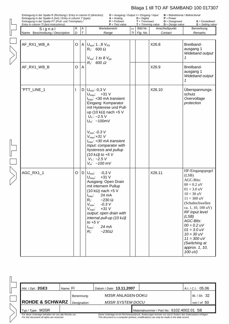
Eintragung in der Spalte R (Richtung) / Entry in column D (direction): O = Ausgang / Output I = Eingang / Input B = Bidirektional / Bidirectional Eintragung in der Spalte A (Art) / Entry in column T (type): A = Analog D = Digital P = Power Eintragung in der Spalte PT (Prüf- und Trimmplan) / P = Prüfwert T = Trimmwert D = Designwert E = Einstellwert Entry in column TI (test instructions): P = Test value T = Trimming value D = Design value E = Setting value
S i g n a l R A Wertebereich PT Bild Nr. Anschlußpunkt Bemerkung Name Beschreibung / Description D T Range TI Fig. No. Contact Remarks
Abt. / Dpt.: 2GE3 Name: Fl Datum / Date: 13.11.2007 Ä.I. / C.I.: 05.06
Benennung: M3SR ANLAGEN-DOKU Bl. / Sh. 32
ROHDE & SCHWARZ Designation: M3SR SYSTEM DOCU von / of 50
Typ / Type: M3SR Materialnummer / Part No.: 6102.4002.01 SB Für diese Unterlage behalten wir uns alle Rechte vor. Diese Unterlage ist ein Rechnerausdruck, Änderungen können nur durch Ändern des Datensatzes erfolgen. For this document all rights are reserved. This document is a computer printout, modifications can only be made in the data record.
AF_RX1_WB_A O A X26.8 Breitband-ausgang 1 Wideband output 1
AF_RX1_WB_B O A
Uaus: 1...8 VSS RI: 600 W
Vout: 1 to 8 Vpp
RI: 600 WX26.9 Breitband-
ausgang 1 Wideband output 1
˜PTT_LINE_1 I D Umin: -0,3 V Umax: +31 V Imax: <30 mA transient Eingang: Komparator mit Hysterese und Pull-up (10 kW) nach +5 V UT-: ~2.5 V UH: ~100mV
Vmin: -0.3 V Vmax:+31 V Imax: <30 mA transient Input: comparator with hysteresis and pullup (10 kW) to +5 V VT-: ~2.5 V VH: ~100 mV
X26.10 Überspannungs-schutz Overvoltage protection
AGC_RX1_1 O D Umin: -0,3 V Umax: +31 V Ausgang: Open Drain mit internem Pullup (10 kW) nach +5 V Imax: 24 mA Ri: ~230 WVmin: -0.3 V Vmax: +31 V output: open drain with internal pull-up (10 kW)to +5 V Imax: 24 mA Ri: ~230W
X26.11 HF-Eingangspegel (LSB) AGC-Bits: 00 = 0.2 uV 01 = 3.0 uV 10 = 30 uV 11 = 300 uV (Schaltschwellen ca. 1, 10, 100 uV) RF input level (LSB) AGC-Bits: 00 = 0.2 uV 01 = 3.0 uV 10 = 30 uV 11 = 300 uV (Swítching at approx. 1, 10, 100 uV)
Bilaga 1 till TO AF SAMBAND 100 017307
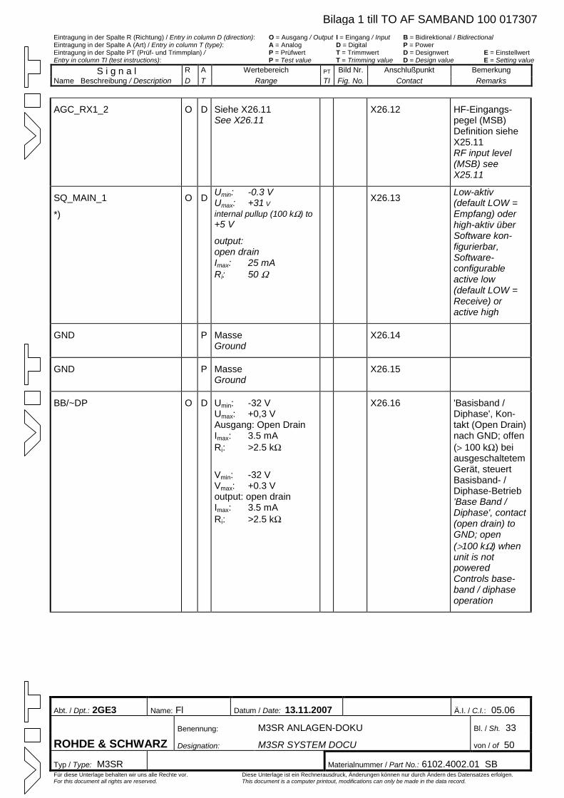
Eintragung in der Spalte R (Richtung) / Entry in column D (direction): O = Ausgang / Output I = Eingang / Input B = Bidirektional / Bidirectional Eintragung in der Spalte A (Art) / Entry in column T (type): A = Analog D = Digital P = Power Eintragung in der Spalte PT (Prüf- und Trimmplan) / P = Prüfwert T = Trimmwert D = Designwert E = Einstellwert Entry in column TI (test instructions): P = Test value T = Trimming value D = Design value E = Setting value
S i g n a l R A Wertebereich PT Bild Nr. Anschlußpunkt Bemerkung Name Beschreibung / Description D T Range TI Fig. No. Contact Remarks
Abt. / Dpt.: 2GE3 Name: Fl Datum / Date: 13.11.2007 Ä.I. / C.I.: 05.06
Benennung: M3SR ANLAGEN-DOKU Bl. / Sh. 33
ROHDE & SCHWARZ Designation: M3SR SYSTEM DOCU von / of 50
Typ / Type: M3SR Materialnummer / Part No.: 6102.4002.01 SB Für diese Unterlage behalten wir uns alle Rechte vor. Diese Unterlage ist ein Rechnerausdruck, Änderungen können nur durch Ändern des Datensatzes erfolgen. For this document all rights are reserved. This document is a computer printout, modifications can only be made in the data record.
AGC_RX1_2 O D Siehe X26.11 See X26.11
X26.12 HF-Eingangs-pegel (MSB) Definition siehe X25.11 RF input level (MSB) see X25.11
SQ_MAIN_1
*)
O D Umin: -0.3 V Umax: +31 Vinternal pullup (100 kW) to +5 V
output: open drain Imax: 25 mA Ri: 50 W
X26.13 Low-aktiv (default LOW = Empfang) oder high-aktiv über Software kon-figurierbar, Software-configurable active low (default LOW = Receive) or active high
GND P Masse Ground
X26.14
GND P Masse Ground
X26.15
BB/~DP O D Umin: -32 V Umax: +0,3 V Ausgang: Open Drain Imax: 3.5 mA Ri: >2.5 kW
Vmin: -32 V Vmax: +0.3 V output: open drain Imax: 3.5 mA Ri: >2.5 kW
X26.16 'Basisband / Diphase', Kon-takt (Open Drain) nach GND; offen (> 100 kW) bei ausgeschaltetem Gerät, steuert Basisband- / Diphase-Betrieb 'Base Band / Diphase', contact (open drain) to GND; open (>100 kW) when unit is not powered Controls base-band / diphase operation
Bilaga 1 till TO AF SAMBAND 100 017307
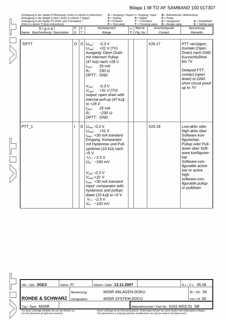
Eintragung in der Spalte R (Richtung) / Entry in column D (direction): O = Ausgang / Output I = Eingang / Input B = Bidirektional / Bidirectional Eintragung in der Spalte A (Art) / Entry in column T (type): A = Analog D = Digital P = Power Eintragung in der Spalte PT (Prüf- und Trimmplan) / P = Prüfwert T = Trimmwert D = Designwert E = Einstellwert Entry in column TI (test instructions): P = Test value T = Trimming value D = Design value E = Setting value
S i g n a l R A Wertebereich PT Bild Nr. Anschlußpunkt Bemerkung Name Beschreibung / Description D T Range TI Fig. No. Contact Remarks
Abt. / Dpt.: 2GE3 Name: Fl Datum / Date: 13.11.2007 Ä.I. / C.I.: 05.06
Benennung: M3SR ANLAGEN-DOKU Bl. / Sh. 34
ROHDE & SCHWARZ Designation: M3SR SYSTEM DOCU von / of 50
Typ / Type: M3SR Materialnummer / Part No.: 6102.4002.01 SB Für diese Unterlage behalten wir uns alle Rechte vor. Diese Unterlage ist ein Rechnerausdruck, Änderungen können nur durch Ändern des Datensatzes erfolgen. For this document all rights are reserved. This document is a computer printout, modifications can only be made in the data record.
˜DPTT O D Umin: -0,3 V Umax: +31 V (7V) Ausgang: Open Drain mit internem Pullup (47 kW) nach +28 V Imax: 25 mA Ri: 230 WDPTT: GND
Vmin: -0.3 V Vmax: +31 V (7V) output: open drain with internal pull-up (47 kW)to +28 V Imax: 25 mA Ri: ~230 WDPTT: GND
X26.17 PTT verzögert, Kontakt (Open Drain) nach GNDKurzschlußfest bis 7V Delayed PTT, contact (open drain) to GND short circuit proof up to 7V
PTT_1 I D Umin: -0,3 V Umax: +31 V Imax: <30 mA transient Eingang: Komparator mit Hysterese und Pull-up/down (10 kW) nach +5 V UT-: ~2.5 V UH: ~100 mV
Vmin: -0.3 V Vmax:+31 V Imax: <30 mA transient Input: comparator with. hysteresis and pullup/ down (10 kW) to +5 V VT-: ~2.5 V VH: ~100 mV
X26.18 Low-aktiv oder high-aktiv über Software kon-figurierbar, Pullup oder Pull-down über Soft-ware konfigurier-bar Software-con-figurable active low or active high, software-con-figurable pullup or pulldown
Bilaga 1 till TO AF SAMBAND 100 017307
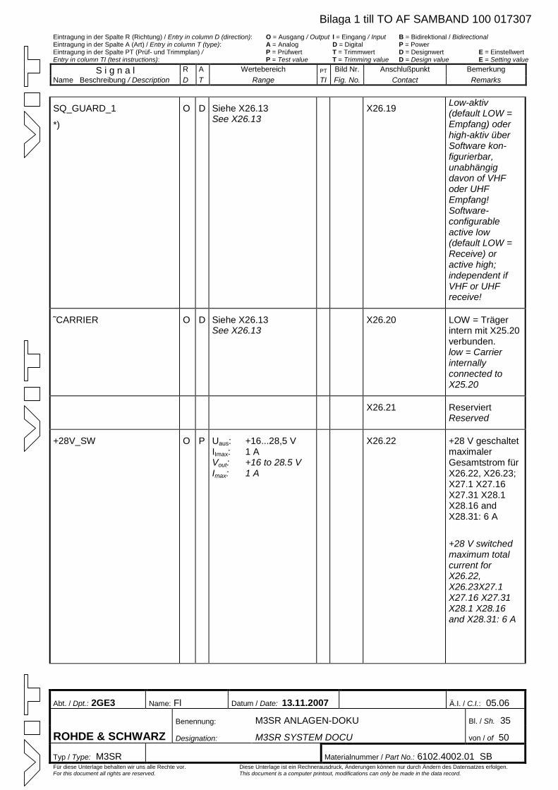
Eintragung in der Spalte R (Richtung) / Entry in column D (direction): O = Ausgang / Output I = Eingang / Input B = Bidirektional / Bidirectional Eintragung in der Spalte A (Art) / Entry in column T (type): A = Analog D = Digital P = Power Eintragung in der Spalte PT (Prüf- und Trimmplan) / P = Prüfwert T = Trimmwert D = Designwert E = Einstellwert Entry in column TI (test instructions): P = Test value T = Trimming value D = Design value E = Setting value
S i g n a l R A Wertebereich PT Bild Nr. Anschlußpunkt Bemerkung Name Beschreibung / Description D T Range TI Fig. No. Contact Remarks
Abt. / Dpt.: 2GE3 Name: Fl Datum / Date: 13.11.2007 Ä.I. / C.I.: 05.06
Benennung: M3SR ANLAGEN-DOKU Bl. / Sh. 35
ROHDE & SCHWARZ Designation: M3SR SYSTEM DOCU von / of 50
Typ / Type: M3SR Materialnummer / Part No.: 6102.4002.01 SB Für diese Unterlage behalten wir uns alle Rechte vor. Diese Unterlage ist ein Rechnerausdruck, Änderungen können nur durch Ändern des Datensatzes erfolgen. For this document all rights are reserved. This document is a computer printout, modifications can only be made in the data record.
SQ_GUARD_1
*)
O D Siehe X26.13 See X26.13
X26.19 Low-aktiv (default LOW = Empfang) oder high-aktiv über Software kon-figurierbar, unabhängig davon of VHF oder UHF Empfang! Software-configurable active low (default LOW = Receive) or active high; independent if VHF or UHF receive!
˜CARRIER O D Siehe X26.13 See X26.13
X26.20 LOW = Träger intern mit X25.20 verbunden. low = Carrier internally connected to X25.20
X26.21 Reserviert Reserved
+28V_SW O P Uaus: +16...28,5 V IImax: 1 AVout: +16 to 28.5 V Imax: 1 A
X26.22 +28 V geschaltet maximaler Gesamtstrom für X26.22, X26.23; X27.1 X27.16 X27.31 X28.1 X28.16 and X28.31: 6 A
+28 V switched maximum total current for X26.22, X26.23X27.1 X27.16 X27.31 X28.1 X28.16 and X28.31: 6 A
Bilaga 1 till TO AF SAMBAND 100 017307
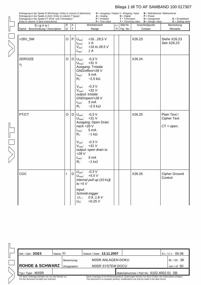
Eintragung in der Spalte R (Richtung) / Entry in column D (direction): O = Ausgang / Output I = Eingang / Input B = Bidirektional / Bidirectional Eintragung in der Spalte A (Art) / Entry in column T (type): A = Analog D = Digital P = Power Eintragung in der Spalte PT (Prüf- und Trimmplan) / P = Prüfwert T = Trimmwert D = Designwert E = Einstellwert Entry in column TI (test instructions): P = Test value T = Trimming value D = Design value E = Setting value
S i g n a l R A Wertebereich PT Bild Nr. Anschlußpunkt Bemerkung Name Beschreibung / Description D T Range TI Fig. No. Contact Remarks
Abt. / Dpt.: 2GE3 Name: Fl Datum / Date: 13.11.2007 Ä.I. / C.I.: 05.06
Benennung: M3SR ANLAGEN-DOKU Bl. / Sh. 36
ROHDE & SCHWARZ Designation: M3SR SYSTEM DOCU von / of 50
Typ / Type: M3SR Materialnummer / Part No.: 6102.4002.01 SB Für diese Unterlage behalten wir uns alle Rechte vor. Diese Unterlage ist ein Rechnerausdruck, Änderungen können nur durch Ändern des Datensatzes erfolgen. For this document all rights are reserved. This document is a computer printout, modifications can only be made in the data record.
+28V_SW O P Uaus: +16...28,5 V IImax: 1 AVout: +16 to 28.5 V Imax: 1 A
X26.23 Siehe X26.23 See X26.23
ZEROIZE
*)
O D Umin: -0,3 V Umax: +31 V Ausgang: Tristate GND/offen/+28 V Imax: 5 mA Ri: ~2.5 kW
Vmin: -0.3 V Vmax: +31 V output: tristate GND/open/+28 V Imax: 5 mA Ri: ~2.5 kW
X26.24
PT/CT O D Umin: -0,3 V Umax: +31 V Ausgang: Open Drain nach +28 V Imax: 5 mA Ri: ~1 kW
Vmin: -0.3 V Vmax: +31 V output: open drain to +28 V Imax: 5 mA Ri: ~1 kW
X26.25 Plain Text / Cipher Text CT = open.
CGC I D Umin: -0.3 V Umax: +5.5 V internal pull up (10 kW)to +5 V
Input: Schmitt-trigger UT-: 0.9..1.8 V UH: >0.25 V
X26.26 Cipher Ground Control
Bilaga 1 till TO AF SAMBAND 100 017307
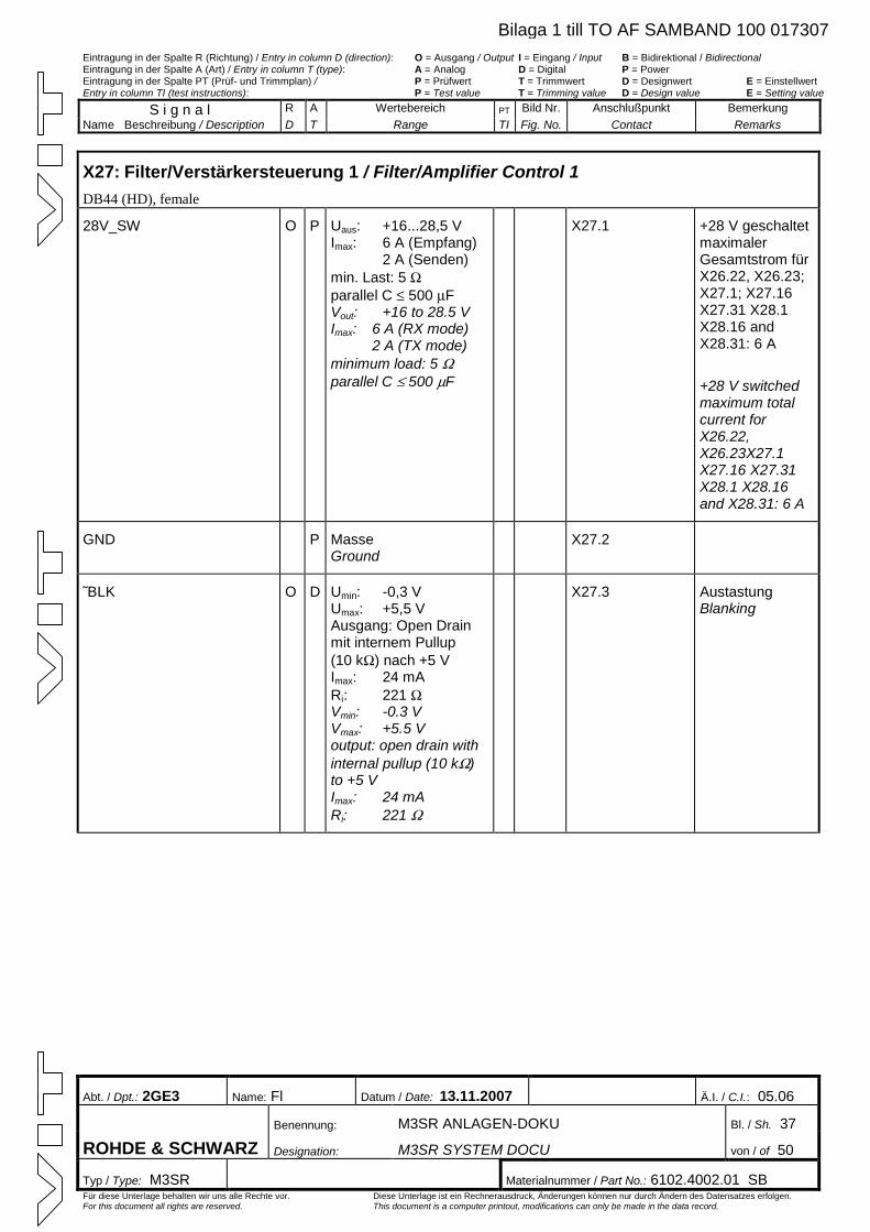
Eintragung in der Spalte R (Richtung) / Entry in column D (direction): O = Ausgang / Output I = Eingang / Input B = Bidirektional / Bidirectional Eintragung in der Spalte A (Art) / Entry in column T (type): A = Analog D = Digital P = Power Eintragung in der Spalte PT (Prüf- und Trimmplan) / P = Prüfwert T = Trimmwert D = Designwert E = Einstellwert Entry in column TI (test instructions): P = Test value T = Trimming value D = Design value E = Setting value
S i g n a l R A Wertebereich PT Bild Nr. Anschlußpunkt Bemerkung Name Beschreibung / Description D T Range TI Fig. No. Contact Remarks
Abt. / Dpt.: 2GE3 Name: Fl Datum / Date: 13.11.2007 Ä.I. / C.I.: 05.06
Benennung: M3SR ANLAGEN-DOKU Bl. / Sh. 37
ROHDE & SCHWARZ Designation: M3SR SYSTEM DOCU von / of 50
Typ / Type: M3SR Materialnummer / Part No.: 6102.4002.01 SB Für diese Unterlage behalten wir uns alle Rechte vor. Diese Unterlage ist ein Rechnerausdruck, Änderungen können nur durch Ändern des Datensatzes erfolgen. For this document all rights are reserved. This document is a computer printout, modifications can only be made in the data record.
X27: Filter/Verstärkersteuerung 1 / Filter/Amplifier Control 1 DB44 (HD), female
28V_SW O P Uaus: +16...28,5 V Imax: 6 A (Empfang) 2 A (Senden) min. Last: 5 Wparallel C £ 500 mFVout: +16 to 28.5 V Imax: 6 A (RX mode)
2 A (TX mode) minimum load: 5 Wparallel C £ 500 mF
X27.1 +28 V geschaltet maximaler Gesamtstrom für X26.22, X26.23; X27.1; X27.16 X27.31 X28.1 X28.16 and X28.31: 6 A
+28 V switched maximum total current for X26.22, X26.23X27.1 X27.16 X27.31 X28.1 X28.16 and X28.31: 6 A
GND P Masse Ground
X27.2
˜BLK O D Umin: -0,3 V Umax: +5,5 V Ausgang: Open Drain mit internem Pullup (10 kW) nach +5 V Imax: 24 mA Ri: 221 WVmin: -0.3 V Vmax: +5.5 V output: open drain with internal pullup (10 kW)to +5 V Imax: 24 mA Ri: 221 W
X27.3 Austastung Blanking
Bilaga 1 till TO AF SAMBAND 100 017307
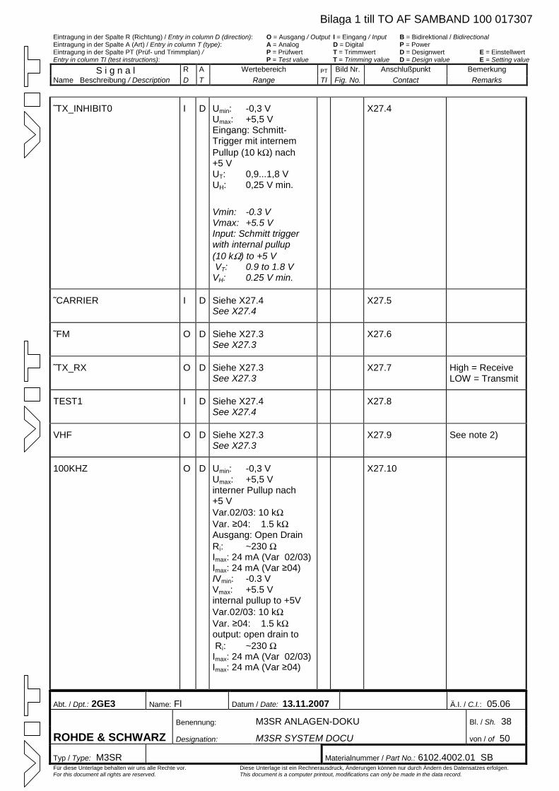
Eintragung in der Spalte R (Richtung) / Entry in column D (direction): O = Ausgang / Output I = Eingang / Input B = Bidirektional / Bidirectional Eintragung in der Spalte A (Art) / Entry in column T (type): A = Analog D = Digital P = Power Eintragung in der Spalte PT (Prüf- und Trimmplan) / P = Prüfwert T = Trimmwert D = Designwert E = Einstellwert Entry in column TI (test instructions): P = Test value T = Trimming value D = Design value E = Setting value
S i g n a l R A Wertebereich PT Bild Nr. Anschlußpunkt Bemerkung Name Beschreibung / Description D T Range TI Fig. No. Contact Remarks
Abt. / Dpt.: 2GE3 Name: Fl Datum / Date: 13.11.2007 Ä.I. / C.I.: 05.06
Benennung: M3SR ANLAGEN-DOKU Bl. / Sh. 38
ROHDE & SCHWARZ Designation: M3SR SYSTEM DOCU von / of 50
Typ / Type: M3SR Materialnummer / Part No.: 6102.4002.01 SB Für diese Unterlage behalten wir uns alle Rechte vor. Diese Unterlage ist ein Rechnerausdruck, Änderungen können nur durch Ändern des Datensatzes erfolgen. For this document all rights are reserved. This document is a computer printout, modifications can only be made in the data record.
˜TX_INHIBIT0 I D Umin: -0,3 V Umax: +5,5 V Eingang: Schmitt-Trigger mit internem Pullup (10 kW) nach +5 VUT: 0,9...1,8 V UH: 0,25 V min.
Vmin: -0.3 V Vmax: +5.5 V Input: Schmitt trigger with internal pullup (10 kW) to +5 V VT: 0.9 to 1.8 V VH: 0.25 V min.
X27.4
˜CARRIER I D Siehe X27.4 See X27.4
X27.5
˜FM O D Siehe X27.3 See X27.3
X27.6
˜TX_RX O D Siehe X27.3 See X27.3
X27.7 High = Receive LOW = Transmit
TEST1 I D Siehe X27.4 See X27.4
X27.8
VHF O D Siehe X27.3 See X27.3
X27.9 See note 2)
100KHZ O D Umin: -0,3 V Umax: +5,5 V interner Pullup nach +5 V Var.02/03: 10 kWVar. ≥04: 1.5 kWAusgang: Open Drain Ri: ~230 WImax: 24 mA (Var 02/03) Imax: 24 mA (Var ≥04) IVmin: -0.3 V Vmax: +5.5 Vinternal pullup to +5V Var.02/03: 10 kWVar. ≥04: 1.5 kWoutput: open drain to Ri: ~230 WImax: 24 mA (Var 02/03) Imax: 24 mA (Var ≥04)
X27.10
Bilaga 1 till TO AF SAMBAND 100 017307
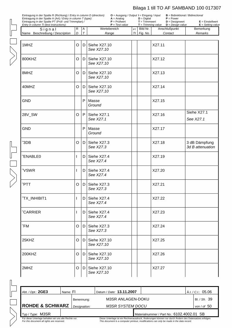
Eintragung in der Spalte R (Richtung) / Entry in column D (direction): O = Ausgang / Output I = Eingang / Input B = Bidirektional / Bidirectional Eintragung in der Spalte A (Art) / Entry in column T (type): A = Analog D = Digital P = Power Eintragung in der Spalte PT (Prüf- und Trimmplan) / P = Prüfwert T = Trimmwert D = Designwert E = Einstellwert Entry in column TI (test instructions): P = Test value T = Trimming value D = Design value E = Setting value
S i g n a l R A Wertebereich PT Bild Nr. Anschlußpunkt Bemerkung Name Beschreibung / Description D T Range TI Fig. No. Contact Remarks
Abt. / Dpt.: 2GE3 Name: Fl Datum / Date: 13.11.2007 Ä.I. / C.I.: 05.06
Benennung: M3SR ANLAGEN-DOKU Bl. / Sh. 39
ROHDE & SCHWARZ Designation: M3SR SYSTEM DOCU von / of 50
Typ / Type: M3SR Materialnummer / Part No.: 6102.4002.01 SB Für diese Unterlage behalten wir uns alle Rechte vor. Diese Unterlage ist ein Rechnerausdruck, Änderungen können nur durch Ändern des Datensatzes erfolgen. For this document all rights are reserved. This document is a computer printout, modifications can only be made in the data record.
1MHZ O D Siehe X27.10 See X27.10
X27.11
800KHZ O D Siehe X27.10 See X27.10
X27.12
8MHZ O D Siehe X27.10 See X27.10
X27.13
40MHZ O D Siehe X27.10 See X27.10
X27.14
GND P Masse Ground
X27.15
28V_SW O P Siehe X27.1 See X27.1
X27.16 Siehe X27.1
See X27.1
GND P Masse Ground
X27.17
˜3DB O D Siehe X27.3 See X27.3
X27.18 3 dB Dämpfung 3d B attenuation
˜ENABLE0 I D Siehe X27.4 See X27.4
X27.19
˜VSWR I D Siehe X27.4 See X27.4
X27.20
˜PTT O D Siehe X27.3 See X27.3
X27.21
˜TX_INHIBIT1 I D Siehe X27.4 See X27.4
X27.22
˜CARRIER I D Siehe X27.4 See X27.4
X27.23
˜FM O D Siehe X27.3 See X27.3
X27.24
25KHZ O D Siehe X27.10 See X27.10
X27.25
200KHZ O D Siehe X27.10 See X27.10
X27.26
2MHZ O D Siehe X27.10 See X27.10
X27.27
Bilaga 1 till TO AF SAMBAND 100 017307
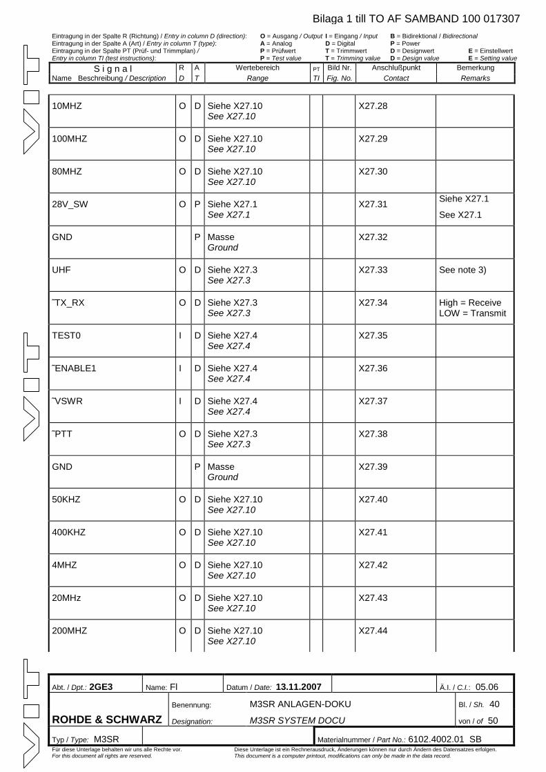
Eintragung in der Spalte R (Richtung) / Entry in column D (direction): O = Ausgang / Output I = Eingang / Input B = Bidirektional / Bidirectional Eintragung in der Spalte A (Art) / Entry in column T (type): A = Analog D = Digital P = Power Eintragung in der Spalte PT (Prüf- und Trimmplan) / P = Prüfwert T = Trimmwert D = Designwert E = Einstellwert Entry in column TI (test instructions): P = Test value T = Trimming value D = Design value E = Setting value
S i g n a l R A Wertebereich PT Bild Nr. Anschlußpunkt Bemerkung Name Beschreibung / Description D T Range TI Fig. No. Contact Remarks
Abt. / Dpt.: 2GE3 Name: Fl Datum / Date: 13.11.2007 Ä.I. / C.I.: 05.06
Benennung: M3SR ANLAGEN-DOKU Bl. / Sh. 40
ROHDE & SCHWARZ Designation: M3SR SYSTEM DOCU von / of 50
Typ / Type: M3SR Materialnummer / Part No.: 6102.4002.01 SB Für diese Unterlage behalten wir uns alle Rechte vor. Diese Unterlage ist ein Rechnerausdruck, Änderungen können nur durch Ändern des Datensatzes erfolgen. For this document all rights are reserved. This document is a computer printout, modifications can only be made in the data record.
10MHZ O D Siehe X27.10 See X27.10
X27.28
100MHZ O D Siehe X27.10 See X27.10
X27.29
80MHZ O D Siehe X27.10 See X27.10
X27.30
28V_SW O P Siehe X27.1 See X27.1
X27.31 Siehe X27.1
See X27.1
GND P Masse Ground
X27.32
UHF O D Siehe X27.3 See X27.3
X27.33 See note 3)
˜TX_RX O D Siehe X27.3 See X27.3
X27.34 High = Receive LOW = Transmit
TEST0 I D Siehe X27.4 See X27.4
X27.35
˜ENABLE1 I D Siehe X27.4 See X27.4
X27.36
˜VSWR I D Siehe X27.4 See X27.4
X27.37
˜PTT O D Siehe X27.3 See X27.3
X27.38
GND P Masse Ground
X27.39
50KHZ O D Siehe X27.10 See X27.10
X27.40
400KHZ O D Siehe X27.10 See X27.10
X27.41
4MHZ O D Siehe X27.10 See X27.10
X27.42
20MHz O D Siehe X27.10 See X27.10
X27.43
200MHZ O D Siehe X27.10 See X27.10
X27.44
Bilaga 1 till TO AF SAMBAND 100 017307
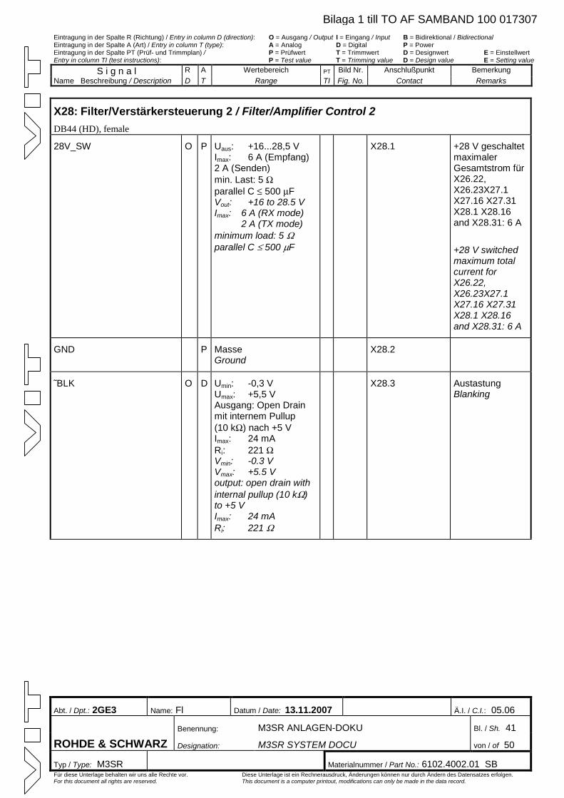
Eintragung in der Spalte R (Richtung) / Entry in column D (direction): O = Ausgang / Output I = Eingang / Input B = Bidirektional / Bidirectional Eintragung in der Spalte A (Art) / Entry in column T (type): A = Analog D = Digital P = Power Eintragung in der Spalte PT (Prüf- und Trimmplan) / P = Prüfwert T = Trimmwert D = Designwert E = Einstellwert Entry in column TI (test instructions): P = Test value T = Trimming value D = Design value E = Setting value
S i g n a l R A Wertebereich PT Bild Nr. Anschlußpunkt Bemerkung Name Beschreibung / Description D T Range TI Fig. No. Contact Remarks
Abt. / Dpt.: 2GE3 Name: Fl Datum / Date: 13.11.2007 Ä.I. / C.I.: 05.06
Benennung: M3SR ANLAGEN-DOKU Bl. / Sh. 41
ROHDE & SCHWARZ Designation: M3SR SYSTEM DOCU von / of 50
Typ / Type: M3SR Materialnummer / Part No.: 6102.4002.01 SB Für diese Unterlage behalten wir uns alle Rechte vor. Diese Unterlage ist ein Rechnerausdruck, Änderungen können nur durch Ändern des Datensatzes erfolgen. For this document all rights are reserved. This document is a computer printout, modifications can only be made in the data record.
X28: Filter/Verstärkersteuerung 2 / Filter/Amplifier Control 2 DB44 (HD), female
28V_SW O P Uaus: +16...28,5 V Imax: 6 A (Empfang) 2 A (Senden) min. Last: 5 Wparallel C £ 500 mFVout: +16 to 28.5 V Imax: 6 A (RX mode)
2 A (TX mode) minimum load: 5 Wparallel C £ 500 mF
X28.1 +28 V geschaltet maximaler Gesamtstrom für X26.22, X26.23X27.1 X27.16 X27.31 X28.1 X28.16 and X28.31: 6 A
+28 V switched maximum total current for X26.22, X26.23X27.1 X27.16 X27.31 X28.1 X28.16 and X28.31: 6 A
GND P Masse Ground
X28.2
˜BLK O D Umin: -0,3 V Umax: +5,5 V Ausgang: Open Drain mit internem Pullup (10 kW) nach +5 V Imax: 24 mA Ri: 221 WVmin: -0.3 V Vmax: +5.5 V output: open drain with internal pullup (10 kW)to +5 V Imax: 24 mA Ri: 221 W
X28.3 Austastung Blanking
Bilaga 1 till TO AF SAMBAND 100 017307
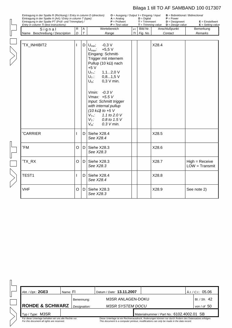
Eintragung in der Spalte R (Richtung) / Entry in column D (direction): O = Ausgang / Output I = Eingang / Input B = Bidirektional / Bidirectional Eintragung in der Spalte A (Art) / Entry in column T (type): A = Analog D = Digital P = Power Eintragung in der Spalte PT (Prüf- und Trimmplan) / P = Prüfwert T = Trimmwert D = Designwert E = Einstellwert Entry in column TI (test instructions): P = Test value T = Trimming value D = Design value E = Setting value
S i g n a l R A Wertebereich PT Bild Nr. Anschlußpunkt Bemerkung Name Beschreibung / Description D T Range TI Fig. No. Contact Remarks
Abt. / Dpt.: 2GE3 Name: Fl Datum / Date: 13.11.2007 Ä.I. / C.I.: 05.06
Benennung: M3SR ANLAGEN-DOKU Bl. / Sh. 42
ROHDE & SCHWARZ Designation: M3SR SYSTEM DOCU von / of 50
Typ / Type: M3SR Materialnummer / Part No.: 6102.4002.01 SB Für diese Unterlage behalten wir uns alle Rechte vor. Diese Unterlage ist ein Rechnerausdruck, Änderungen können nur durch Ändern des Datensatzes erfolgen. For this document all rights are reserved. This document is a computer printout, modifications can only be made in the data record.
˜TX_INHIBIT2 I D Umin: -0,3 V Umax: +5,5 V Eingang: Schmitt-Trigger mit internem Pullup (10 kW) nach +5 VUT+: 1,1...2,0 V UT-: 0,8...1,5 V UH: 0,3 V min.
Vmin: -0.3 V Vmax: +5.5 V Input: Schmitt trigger with internal pullup (10 kW) to +5 V VT+: 1.1 to 2.0 V VT-: 0.8 to 1.5 V VH: 0.3 V min.
X28.4
˜CARRIER I D Siehe X28.4 See X28.4
X28.5
˜FM O D Siehe X28.3 See X28.3
X28.6
˜TX_RX O D Siehe X28.3 See X28.3
X28.7 High = Receive LOW = Transmit
TEST1 I D Siehe X28.4 See X28.4
X28.8
VHF O D Siehe X28.3 See X28.3
X28.9 See note 2)
Bilaga 1 till TO AF SAMBAND 100 017307
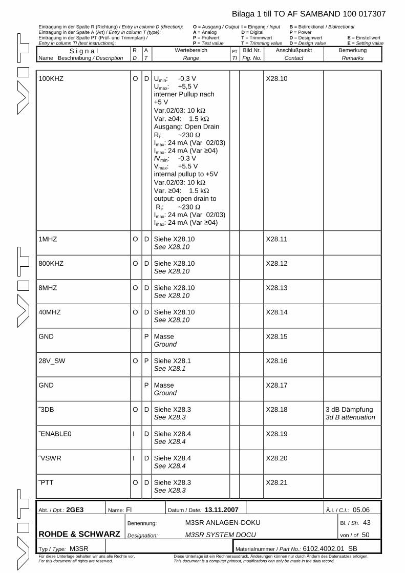
Eintragung in der Spalte R (Richtung) / Entry in column D (direction): O = Ausgang / Output I = Eingang / Input B = Bidirektional / Bidirectional Eintragung in der Spalte A (Art) / Entry in column T (type): A = Analog D = Digital P = Power Eintragung in der Spalte PT (Prüf- und Trimmplan) / P = Prüfwert T = Trimmwert D = Designwert E = Einstellwert Entry in column TI (test instructions): P = Test value T = Trimming value D = Design value E = Setting value
S i g n a l R A Wertebereich PT Bild Nr. Anschlußpunkt Bemerkung Name Beschreibung / Description D T Range TI Fig. No. Contact Remarks
Abt. / Dpt.: 2GE3 Name: Fl Datum / Date: 13.11.2007 Ä.I. / C.I.: 05.06
Benennung: M3SR ANLAGEN-DOKU Bl. / Sh. 43
ROHDE & SCHWARZ Designation: M3SR SYSTEM DOCU von / of 50
Typ / Type: M3SR Materialnummer / Part No.: 6102.4002.01 SB Für diese Unterlage behalten wir uns alle Rechte vor. Diese Unterlage ist ein Rechnerausdruck, Änderungen können nur durch Ändern des Datensatzes erfolgen. For this document all rights are reserved. This document is a computer printout, modifications can only be made in the data record.
100KHZ O D Umin: -0,3 V Umax: +5,5 V interner Pullup nach +5 V Var.02/03: 10 kWVar. ≥04: 1.5 kWAusgang: Open Drain Ri: ~230 WImax: 24 mA (Var 02/03) Imax: 24 mA (Var ≥04) IVmin: -0.3 V Vmax: +5.5 Vinternal pullup to +5V Var.02/03: 10 kWVar. ≥04: 1.5 kWoutput: open drain to Ri: ~230 WImax: 24 mA (Var 02/03) Imax: 24 mA (Var ≥04)
X28.10
1MHZ O D Siehe X28.10 See X28.10
X28.11
800KHZ O D Siehe X28.10 See X28.10
X28.12
8MHZ O D Siehe X28.10 See X28.10
X28.13
40MHZ O D Siehe X28.10 See X28.10
X28.14
GND P Masse Ground
X28.15
28V_SW O P Siehe X28.1 See X28.1
X28.16
GND P Masse Ground
X28.17
˜3DB O D Siehe X28.3 See X28.3
X28.18 3 dB Dämpfung 3d B attenuation
˜ENABLE0 I D Siehe X28.4 See X28.4
X28.19
˜VSWR I D Siehe X28.4 See X28.4
X28.20
˜PTT O D Siehe X28.3 See X28.3
X28.21
Bilaga 1 till TO AF SAMBAND 100 017307
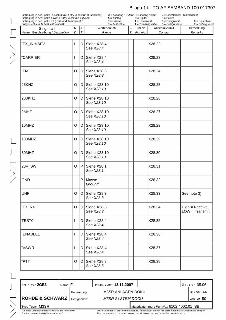
Eintragung in der Spalte R (Richtung) / Entry in column D (direction): O = Ausgang / Output I = Eingang / Input B = Bidirektional / Bidirectional Eintragung in der Spalte A (Art) / Entry in column T (type): A = Analog D = Digital P = Power Eintragung in der Spalte PT (Prüf- und Trimmplan) / P = Prüfwert T = Trimmwert D = Designwert E = Einstellwert Entry in column TI (test instructions): P = Test value T = Trimming value D = Design value E = Setting value
S i g n a l R A Wertebereich PT Bild Nr. Anschlußpunkt Bemerkung Name Beschreibung / Description D T Range TI Fig. No. Contact Remarks
Abt. / Dpt.: 2GE3 Name: Fl Datum / Date: 13.11.2007 Ä.I. / C.I.: 05.06
Benennung: M3SR ANLAGEN-DOKU Bl. / Sh. 44
ROHDE & SCHWARZ Designation: M3SR SYSTEM DOCU von / of 50
Typ / Type: M3SR Materialnummer / Part No.: 6102.4002.01 SB Für diese Unterlage behalten wir uns alle Rechte vor. Diese Unterlage ist ein Rechnerausdruck, Änderungen können nur durch Ändern des Datensatzes erfolgen. For this document all rights are reserved. This document is a computer printout, modifications can only be made in the data record.
˜TX_INHIBIT3 I D Siehe X28.4 See X28.4
X28.22
˜CARRIER I D Siehe X28.4 See X28.4
X28.23
˜FM O D Siehe X28.3 See X28.3
X28.24
25KHZ O D Siehe X28.10 See X28.10
X28.25
200KHZ O D Siehe X28.10 See X28.10
X28.26
2MHZ O D Siehe X28.10 See X28.10
X28.27
10MHZ O D Siehe X28.10 See X28.10
X28.28
100MHZ O D Siehe X28.10 See X28.10
X28.29
80MHZ O D Siehe X28.10 See X28.10
X28.30
28V_SW O P Siehe X28.1 See X28.1
X28.31
GND P Masse Ground
X28.32
UHF O D Siehe X28.3 See X28.3
X28.33 See note 3)
˜TX_RX O D Siehe X28.3 See X28.3
X28.34 High = Receive LOW = Transmit
TEST0 I D Siehe X28.4 See X28.4
X28.35
˜ENABLE1 I D Siehe X28.4 See X28.4
X28.36
˜VSWR I D Siehe X28.4 See X28.4
X28.37
˜PTT O D Siehe X28.3 See X28.3
X28.38
Bilaga 1 till TO AF SAMBAND 100 017307
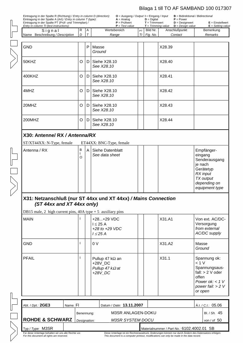
Eintragung in der Spalte R (Richtung) / Entry in column D (direction): O = Ausgang / Output I = Eingang / Input B = Bidirektional / Bidirectional Eintragung in der Spalte A (Art) / Entry in column T (type): A = Analog D = Digital P = Power Eintragung in der Spalte PT (Prüf- und Trimmplan) / P = Prüfwert T = Trimmwert D = Designwert E = Einstellwert Entry in column TI (test instructions): P = Test value T = Trimming value D = Design value E = Setting value
S i g n a l R A Wertebereich PT Bild Nr. Anschlußpunkt Bemerkung Name Beschreibung / Description D T Range TI Fig. No. Contact Remarks
Abt. / Dpt.: 2GE3 Name: Fl Datum / Date: 13.11.2007 Ä.I. / C.I.: 05.06
Benennung: M3SR ANLAGEN-DOKU Bl. / Sh. 45
ROHDE & SCHWARZ Designation: M3SR SYSTEM DOCU von / of 50
Typ / Type: M3SR Materialnummer / Part No.: 6102.4002.01 SB Für diese Unterlage behalten wir uns alle Rechte vor. Diese Unterlage ist ein Rechnerausdruck, Änderungen können nur durch Ändern des Datensatzes erfolgen. For this document all rights are reserved. This document is a computer printout, modifications can only be made in the data record.
GND P Masse Ground
X28.39
50KHZ O D Siehe X28.10 See X28.10
X28.40
400KHZ O D Siehe X28.10 See X28.10
X28.41
4MHZ O D Siehe X28.10 See X28.10
X28.42
20MHZ O D Siehe X28.10 See X28.10
X28.43
200MHZ O D Siehe X28.10 See X28.10
X28.44
X30: Antenne/ RX / Antenna/RX ST/XT44XX: N-Type, female ET44XX: BNC-Type, female
Antenna / RX BIO
A Siehe Datenblatt See data sheet
Empfänger-eingang Senderausgang je nach Gerätetyp RX input TX output depending on equipment type
X31: Netzanschluß (nur ST 44xx und XT 44xx) / Mains Connection (ST 44xx and XT 44xx only)
DB15 male, 2 high current pins, 40A type + 5 auxiliary pins
MAIN I +28...+29 VDC I £ 25 A +28 to +29 VDC I £ 25 A
X31.A1 Von ext. AC/DC-Versorgung from external AC/DC supply
GND I 0 V X31.A2 Masse Ground
PFAIL I Pullup 47 kW an +28V_DC Pullup 47 kW at +28V_DC
X31.1 Spannung ok: < 1 VSpannungsaus-fall: > 2 V oder offen Power ok: < 1 V power fail: > 2 V or open
Bilaga 1 till TO AF SAMBAND 100 017307
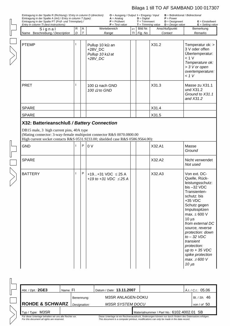
Eintragung in der Spalte R (Richtung) / Entry in column D (direction): O = Ausgang / Output I = Eingang / Input B = Bidirektional / Bidirectional Eintragung in der Spalte A (Art) / Entry in column T (type): A = Analog D = Digital P = Power Eintragung in der Spalte PT (Prüf- und Trimmplan) / P = Prüfwert T = Trimmwert D = Designwert E = Einstellwert Entry in column TI (test instructions): P = Test value T = Trimming value D = Design value E = Setting value
S i g n a l R A Wertebereich PT Bild Nr. Anschlußpunkt Bemerkung Name Beschreibung / Description D T Range TI Fig. No. Contact Remarks
Abt. / Dpt.: 2GE3 Name: Fl Datum / Date: 13.11.2007 Ä.I. / C.I.: 05.06
Benennung: M3SR ANLAGEN-DOKU Bl. / Sh. 46
ROHDE & SCHWARZ Designation: M3SR SYSTEM DOCU von / of 50
Typ / Type: M3SR Materialnummer / Part No.: 6102.4002.01 SB Für diese Unterlage behalten wir uns alle Rechte vor. Diese Unterlage ist ein Rechnerausdruck, Änderungen können nur durch Ändern des Datensatzes erfolgen. For this document all rights are reserved. This document is a computer printout, modifications can only be made in the data record.
PTEMP I Pullup 10 kW an +28V_DC Pullup 10 kW at +28V_DC
X31.2 Temperatur ok: > 3 V oder offen Übertemperatur: < 1 VTemperature ok: > 3 V or open overtemperature: < 1 V
PRET I 100 W nach GND 100 W to GND
X31.3 Masse zu X31.1 und X31.2 Ground to X31.1 and X31.2
SPARE X31.4
SPARE X31.5
X32: Batterieanschluß / Battery Connection DB15 male, 3 high current pins, 40A type (Mating connector: 3-way-female multipoint connector R&S 0070.0800.00 High current socket contacts R&S 0531.9233.00; shielded case R&S 0586.9564.00):
GND I P 0 V X32.A1 Masse Ground
SPARE X32.A2 Nicht verwendet Not used
BATTERY I P +19...+31 VDC £ 25 A +19 to +31 VDC £ 25 A
X32.A3 Von ext. DC-Quelle, Rück-leistungsschutz: bis –32 VDC Transienten-schutz: bis +35 VDC Schutz gegen Impulsspitzen max. ± 600 V 10 msfrom external DC source, reverse protection: down to – 32 VDC transient protection: up to + 35 VDC spike protection max. ± 600 V 10 ms
Bilaga 1 till TO AF SAMBAND 100 017307
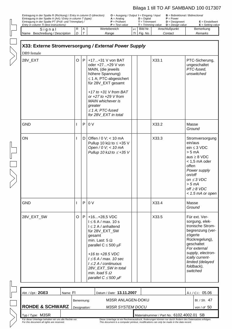
Eintragung in der Spalte R (Richtung) / Entry in column D (direction): O = Ausgang / Output I = Eingang / Input B = Bidirektional / Bidirectional Eintragung in der Spalte A (Art) / Entry in column T (type): A = Analog D = Digital P = Power Eintragung in der Spalte PT (Prüf- und Trimmplan) / P = Prüfwert T = Trimmwert D = Designwert E = Einstellwert Entry in column TI (test instructions): P = Test value T = Trimming value D = Design value E = Setting value
S i g n a l R A Wertebereich PT Bild Nr. Anschlußpunkt Bemerkung Name Beschreibung / Description D T Range TI Fig. No. Contact Remarks
Abt. / Dpt.: 2GE3 Name: Fl Datum / Date: 13.11.2007 Ä.I. / C.I.: 05.06
Benennung: M3SR ANLAGEN-DOKU Bl. / Sh. 47
ROHDE & SCHWARZ Designation: M3SR SYSTEM DOCU von / of 50
Typ / Type: M3SR Materialnummer / Part No.: 6102.4002.01 SB Für diese Unterlage behalten wir uns alle Rechte vor. Diese Unterlage ist ein Rechnerausdruck, Änderungen können nur durch Ändern des Datensatzes erfolgen. For this document all rights are reserved. This document is a computer printout, modifications can only be made in the data record.
X33: Externe Stromversorgung / External Power Supply DB9 female
28V_EXT O P +17...+31 V von BAT oder +27...+29 V von MAIN, (die jeweils höhere Spannung) £ 1 A; PTC-abgesichertfür 28V_EXT gesamt +17 to +31 V from BAT or +27 to +29 V from MAIN whichever is greater £ 1 A; PTC-fused for 28V_EXT in total
X33.1 PTC-Sicherung, ungeschaltet PTC-fused, unswitched
GND I P 0 V X33.2 Masse Ground
ON I D Offen / 0 V; < 10 mA Pullup 10 kW to £ +35 VOpen / 0 V; < 10 mA Pullup 10 kW to £ +35 V
X33.3 Stromversorgung ein/aus ein £ 3 VDC > 5 mA aus ³ 8 VDC < 1,5 mA oder offen Power supply on/off on £ 3 VDC > 5 mA off ³ 8 VDC < 1.5 mA or open
GND I P 0 V X33.4 Masse Ground
28V_EXT_SW O P +16...+28,5 VDC I £ 6 A / max. 10 s I £ 2 A / anhaltend für 28V_EXT_SW gesamt min. Last: 5 Wparallel C £ 500 mF
+16 to +28.5 VDC I £ 6 A / max. 10 sec I £ 2 A / continuous 28V_EXT_SW in total min. load 5 Wparallel C £ 500 mF
X33.5 Für ext. Ver-sorgung, elek-tronische Strom-begrenzung (ver-zögerte Rückregelung), geschaltet For external supply, electron-ically current-limited (delayed foldback), switched
Bilaga 1 till TO AF SAMBAND 100 017307
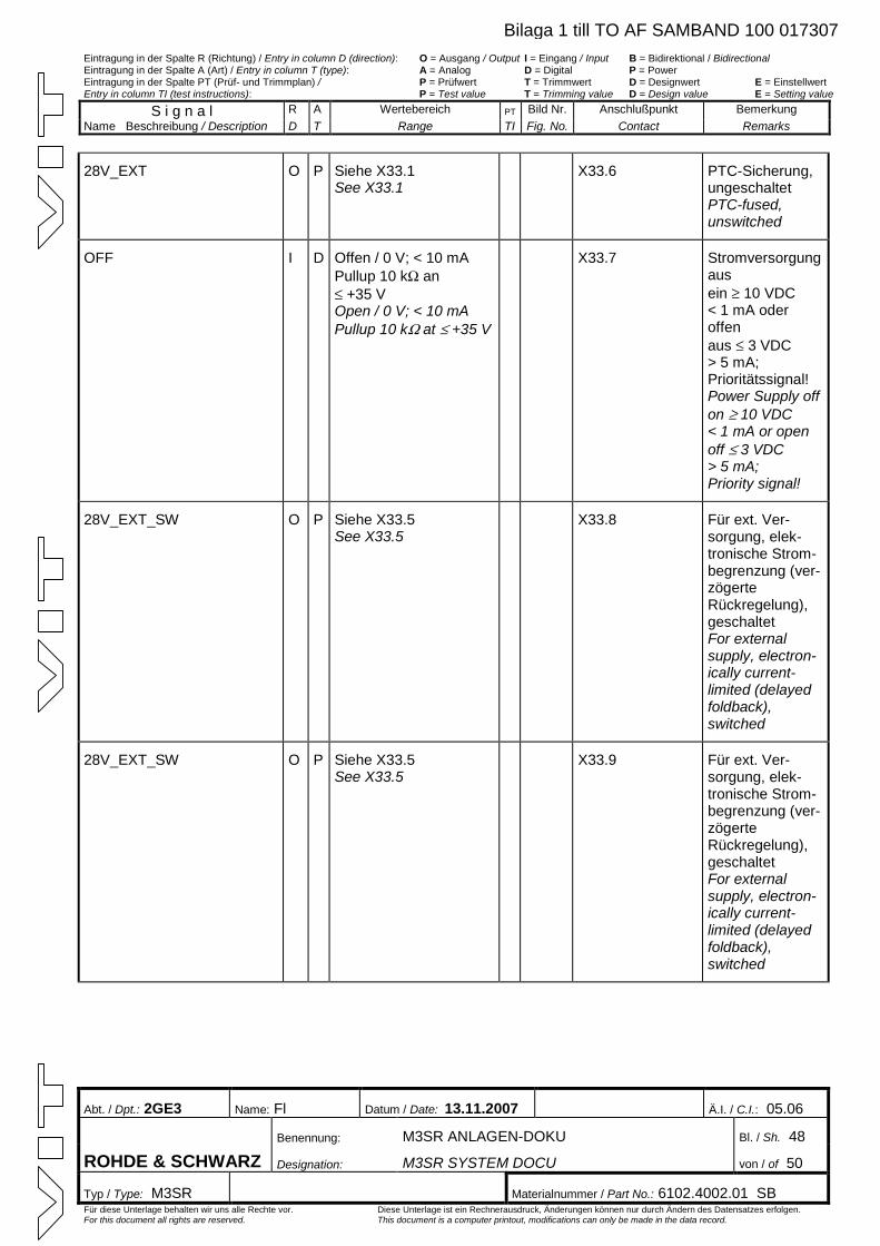
Eintragung in der Spalte R (Richtung) / Entry in column D (direction): O = Ausgang / Output I = Eingang / Input B = Bidirektional / Bidirectional Eintragung in der Spalte A (Art) / Entry in column T (type): A = Analog D = Digital P = Power Eintragung in der Spalte PT (Prüf- und Trimmplan) / P = Prüfwert T = Trimmwert D = Designwert E = Einstellwert Entry in column TI (test instructions): P = Test value T = Trimming value D = Design value E = Setting value
S i g n a l R A Wertebereich PT Bild Nr. Anschlußpunkt Bemerkung Name Beschreibung / Description D T Range TI Fig. No. Contact Remarks
Abt. / Dpt.: 2GE3 Name: Fl Datum / Date: 13.11.2007 Ä.I. / C.I.: 05.06
Benennung: M3SR ANLAGEN-DOKU Bl. / Sh. 48
ROHDE & SCHWARZ Designation: M3SR SYSTEM DOCU von / of 50
Typ / Type: M3SR Materialnummer / Part No.: 6102.4002.01 SB Für diese Unterlage behalten wir uns alle Rechte vor. Diese Unterlage ist ein Rechnerausdruck, Änderungen können nur durch Ändern des Datensatzes erfolgen. For this document all rights are reserved. This document is a computer printout, modifications can only be made in the data record.
28V_EXT O P Siehe X33.1 See X33.1
X33.6 PTC-Sicherung, ungeschaltet PTC-fused, unswitched
OFF I D Offen / 0 V; < 10 mA Pullup 10 kW an £ +35 V Open / 0 V; < 10 mA Pullup 10 kW at £ +35 V
X33.7 Stromversorgung aus ein ³ 10 VDC < 1 mA oder offen aus £ 3 VDC > 5 mA; Prioritätssignal! Power Supply offon ³ 10 VDC < 1 mA or open off £ 3 VDC > 5 mA; Priority signal!
28V_EXT_SW O P Siehe X33.5 See X33.5
X33.8 Für ext. Ver-sorgung, elek-tronische Strom-begrenzung (ver-zögerte Rückregelung), geschaltet For external supply, electron-ically current-limited (delayed foldback), switched
28V_EXT_SW O P Siehe X33.5 See X33.5
X33.9 Für ext. Ver-sorgung, elek-tronische Strom-begrenzung (ver-zögerte Rückregelung), geschaltet For external supply, electron-ically current-limited (delayed foldback), switched
Bilaga 1 till TO AF SAMBAND 100 017307
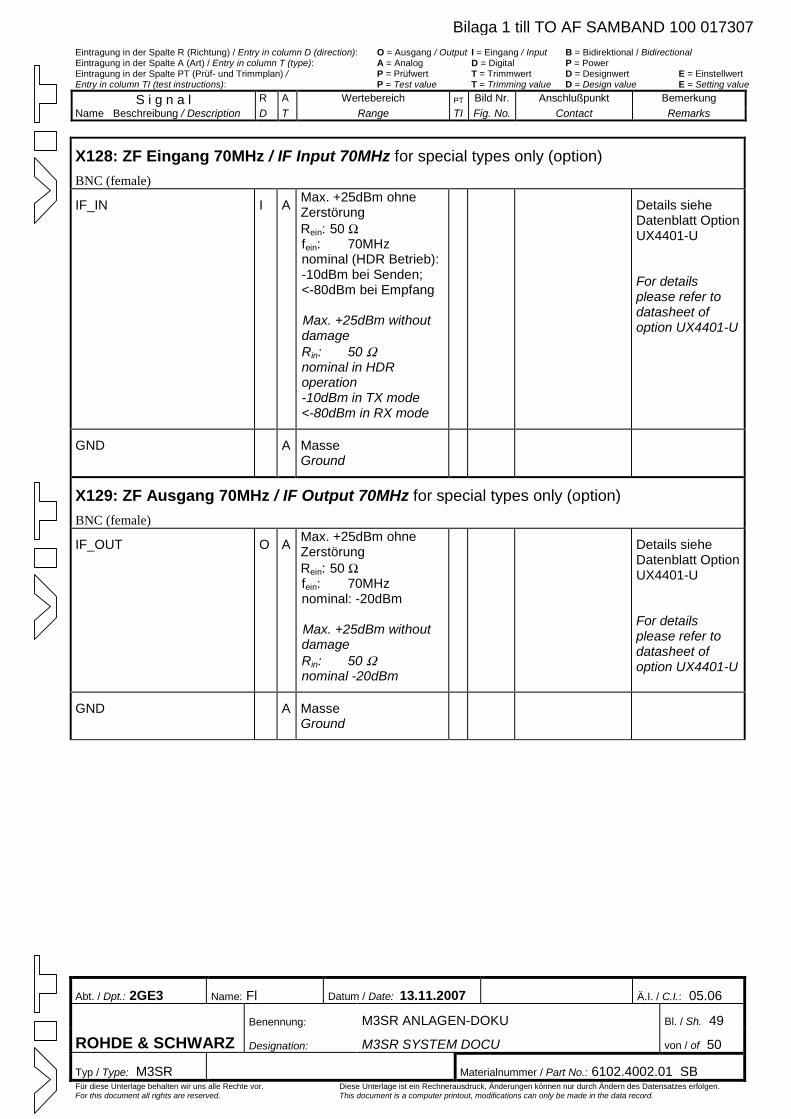
Eintragung in der Spalte R (Richtung) / Entry in column D (direction): O = Ausgang / Output I = Eingang / Input B = Bidirektional / Bidirectional Eintragung in der Spalte A (Art) / Entry in column T (type): A = Analog D = Digital P = Power Eintragung in der Spalte PT (Prüf- und Trimmplan) / P = Prüfwert T = Trimmwert D = Designwert E = Einstellwert Entry in column TI (test instructions): P = Test value T = Trimming value D = Design value E = Setting value
S i g n a l R A Wertebereich PT Bild Nr. Anschlußpunkt Bemerkung Name Beschreibung / Description D T Range TI Fig. No. Contact Remarks
Abt. / Dpt.: 2GE3 Name: Fl Datum / Date: 13.11.2007 Ä.I. / C.I.: 05.06
Benennung: M3SR ANLAGEN-DOKU Bl. / Sh. 49
ROHDE & SCHWARZ Designation: M3SR SYSTEM DOCU von / of 50
Typ / Type: M3SR Materialnummer / Part No.: 6102.4002.01 SB Für diese Unterlage behalten wir uns alle Rechte vor. Diese Unterlage ist ein Rechnerausdruck, Änderungen können nur durch Ändern des Datensatzes erfolgen. For this document all rights are reserved. This document is a computer printout, modifications can only be made in the data record.
X128: ZF Eingang 70MHz / IF Input 70MHz for special types only (option) BNC (female)
IF_IN I A Max. +25dBm ohne Zerstörung Rein: 50 Wfein: 70MHz nominal (HDR Betrieb): -10dBm bei Senden; <-80dBm bei Empfang Max. +25dBm without damage Rin: 50 Wnominal in HDR operation -10dBm in TX mode <-80dBm in RX mode
Details siehe Datenblatt Option UX4401-U
For details please refer to datasheet of option UX4401-U
GND A Masse Ground
X129: ZF Ausgang 70MHz / IF Output 70MHz for special types only (option) BNC (female)
IF_OUT O A Max. +25dBm ohne Zerstörung Rein: 50 Wfein: 70MHz nominal: -20dBm Max. +25dBm without damage Rin: 50 Wnominal -20dBm
Details siehe Datenblatt Option UX4401-U
For details please refer to datasheet of option UX4401-U
GND A Masse Ground
Bilaga 1 till TO AF SAMBAND 100 017307
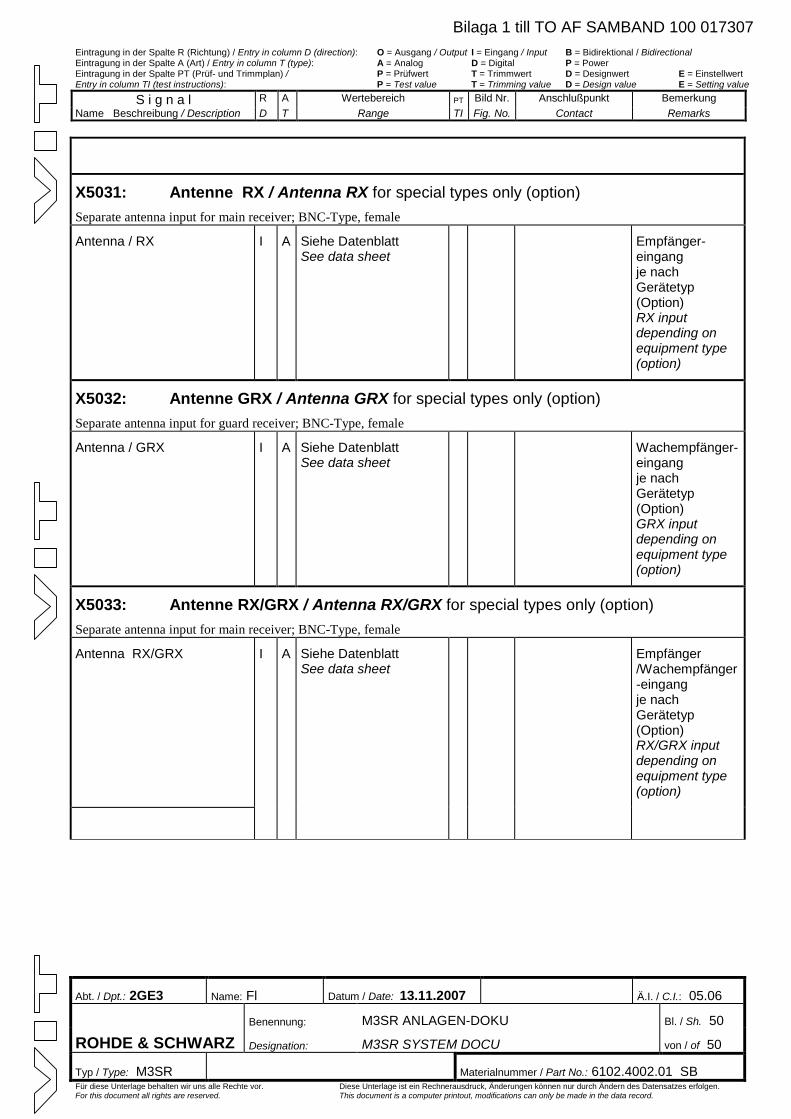
Eintragung in der Spalte R (Richtung) / Entry in column D (direction): O = Ausgang / Output I = Eingang / Input B = Bidirektional / Bidirectional Eintragung in der Spalte A (Art) / Entry in column T (type): A = Analog D = Digital P = Power Eintragung in der Spalte PT (Prüf- und Trimmplan) / P = Prüfwert T = Trimmwert D = Designwert E = Einstellwert Entry in column TI (test instructions): P = Test value T = Trimming value D = Design value E = Setting value
S i g n a l R A Wertebereich PT Bild Nr. Anschlußpunkt Bemerkung Name Beschreibung / Description D T Range TI Fig. No. Contact Remarks
Abt. / Dpt.: 2GE3 Name: Fl Datum / Date: 13.11.2007 Ä.I. / C.I.: 05.06
Benennung: M3SR ANLAGEN-DOKU Bl. / Sh. 50
ROHDE & SCHWARZ Designation: M3SR SYSTEM DOCU von / of 50
Typ / Type: M3SR Materialnummer / Part No.: 6102.4002.01 SB Für diese Unterlage behalten wir uns alle Rechte vor. Diese Unterlage ist ein Rechnerausdruck, Änderungen können nur durch Ändern des Datensatzes erfolgen. For this document all rights are reserved. This document is a computer printout, modifications can only be made in the data record.
X5031: Antenne RX / Antenna RX for special types only (option) Separate antenna input for main receiver; BNC-Type, female
Antenna / RX I A Siehe Datenblatt See data sheet
Empfänger-eingang je nach Gerätetyp (Option) RX input depending on equipment type (option)
X5032: Antenne GRX / Antenna GRX for special types only (option) Separate antenna input for guard receiver; BNC-Type, female
Antenna / GRX I A Siehe Datenblatt See data sheet
Wachempfänger-eingang je nach Gerätetyp (Option) GRX input depending on equipment type (option)
X5033: Antenne RX/GRX / Antenna RX/GRX for special types only (option) Separate antenna input for main receiver; BNC-Type, female
Antenna RX/GRX I A Siehe Datenblatt See data sheet
Empfänger /Wachempfänger-eingang je nach Gerätetyp (Option) RX/GRX input depending on equipment type (option)
Bilaga 1 till TO AF SAMBAND 100 017307
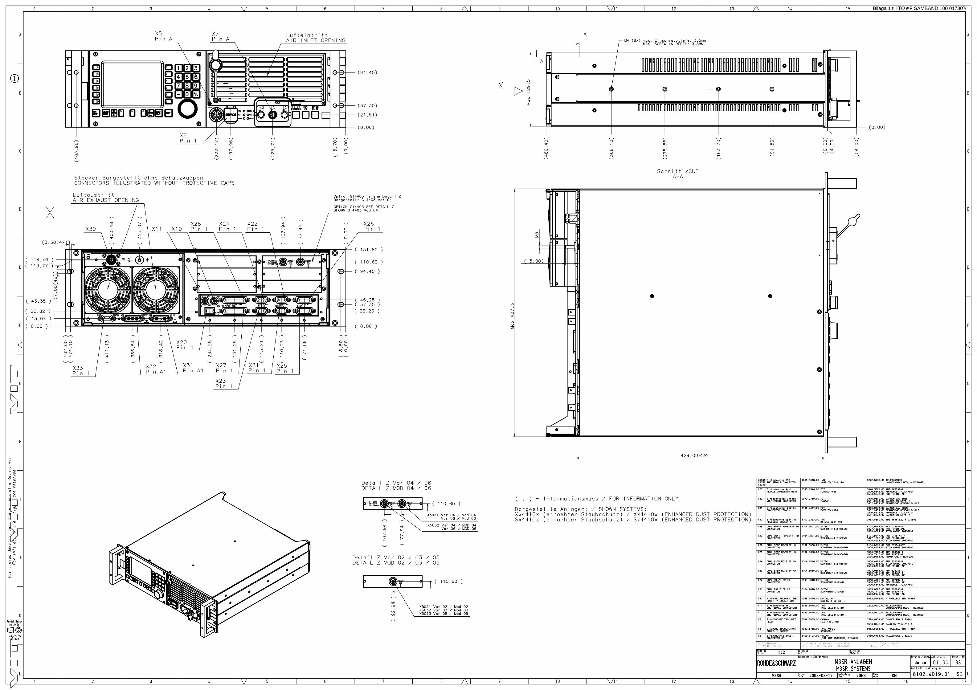
Bilaga 1 till TO AF SAMBAND 100 017307
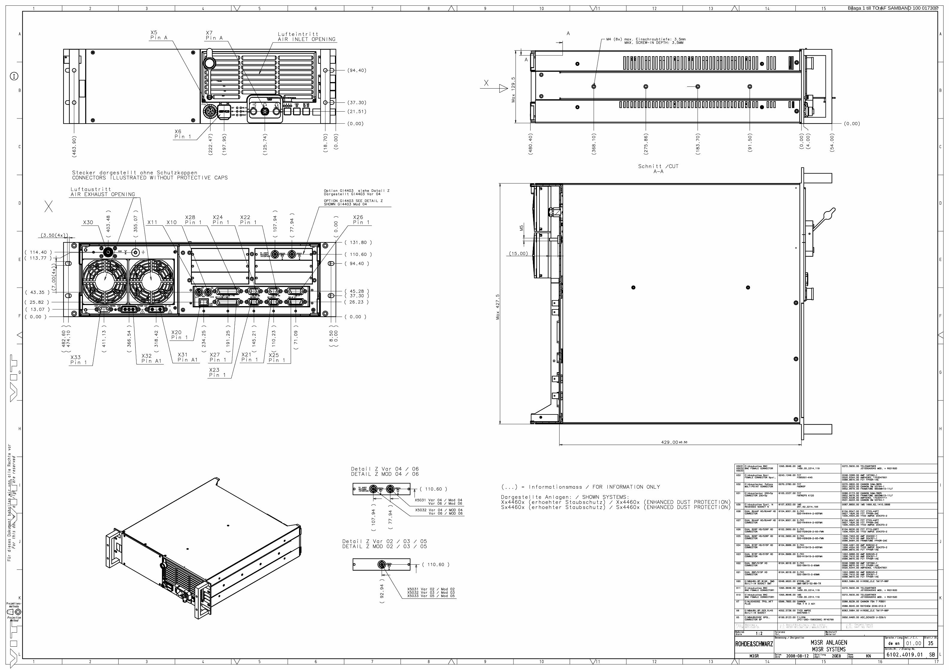
Bilaga 1 till TO AF SAMBAND 100 017307
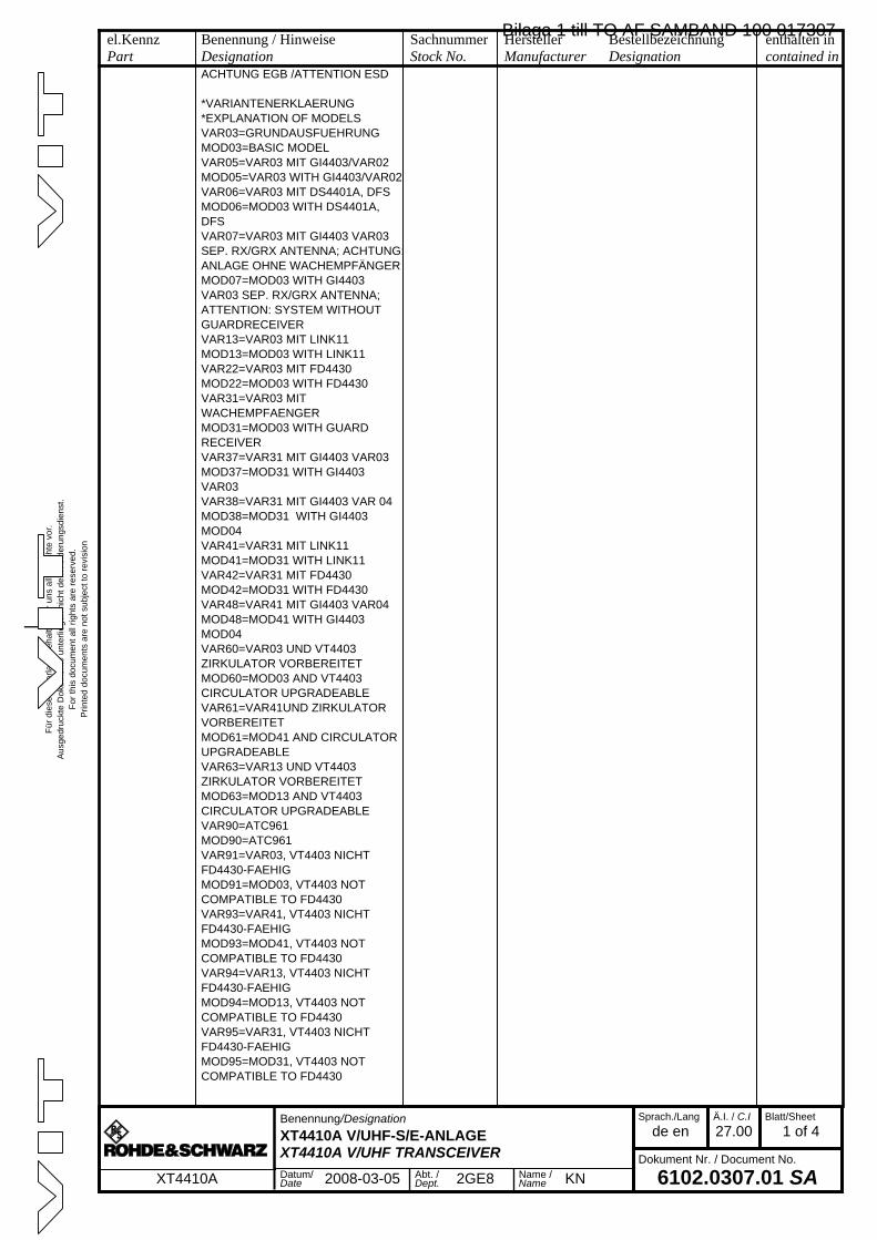
Für
die
se U
nter
lage
beh
alte
n w
ir un
s al
le R
echt
e vo
r.A
usge
druc
kte
Dok
umen
te u
nter
liege
n ni
cht d
em Ä
nder
ungs
dien
st.
For
this
doc
umen
t all
right
s ar
e re
serv
ed.
Prin
ted
docu
men
ts a
re n
ot s
ubje
ct to
rev
isio
n
_
el.KennzPart
Benennung / HinweiseDesignation
SachnummerStock No.
HerstellerManufacturer
BestellbezeichnungDesignation
enthalten incontained in
a
Benennung/Designation
XT4410A V/UHF-S/E-ANLAGEXT4410A V/UHF TRANSCEIVER
Sprach./Lang
de enÄ.I. / C.I
27.00Blatt/Sheet
1 of 4
Dokument Nr. / Document No.
6102.0307.01 SAXT4410A Datum/Date 2008-03-05 Abt. /
Dept. 2GE8 Name /Name KN
ACHTUNG EGB /ATTENTION ESD
*VARIANTENERKLAERUNG*EXPLANATION OF MODELSVAR03=GRUNDAUSFUEHRUNGMOD03=BASIC MODELVAR05=VAR03 MIT GI4403/VAR02MOD05=VAR03 WITH GI4403/VAR02VAR06=VAR03 MIT DS4401A, DFSMOD06=MOD03 WITH DS4401A, DFSVAR07=VAR03 MIT GI4403 VAR03 SEP. RX/GRX ANTENNA; ACHTUNG: ANLAGE OHNE WACHEMPFÄNGERMOD07=MOD03 WITH GI4403 VAR03 SEP. RX/GRX ANTENNA; ATTENTION: SYSTEM WITHOUT GUARDRECEIVERVAR13=VAR03 MIT LINK11MOD13=MOD03 WITH LINK11VAR22=VAR03 MIT FD4430MOD22=MOD03 WITH FD4430VAR31=VAR03 MIT WACHEMPFAENGERMOD31=MOD03 WITH GUARD RECEIVERVAR37=VAR31 MIT GI4403 VAR03MOD37=MOD31 WITH GI4403 VAR03VAR38=VAR31 MIT GI4403 VAR 04MOD38=MOD31 WITH GI4403 MOD04VAR41=VAR31 MIT LINK11MOD41=MOD31 WITH LINK11VAR42=VAR31 MIT FD4430MOD42=MOD31 WITH FD4430VAR48=VAR41 MIT GI4403 VAR04MOD48=MOD41 WITH GI4403 MOD04VAR60=VAR03 UND VT4403 ZIRKULATOR VORBEREITETMOD60=MOD03 AND VT4403 CIRCULATOR UPGRADEABLEVAR61=VAR41UND ZIRKULATOR VORBEREITETMOD61=MOD41 AND CIRCULATOR UPGRADEABLEVAR63=VAR13 UND VT4403 ZIRKULATOR VORBEREITETMOD63=MOD13 AND VT4403 CIRCULATOR UPGRADEABLEVAR90=ATC961MOD90=ATC961VAR91=VAR03, VT4403 NICHT FD4430-FAEHIGMOD91=MOD03, VT4403 NOT COMPATIBLE TO FD4430VAR93=VAR41, VT4403 NICHT FD4430-FAEHIGMOD93=MOD41, VT4403 NOT COMPATIBLE TO FD4430VAR94=VAR13, VT4403 NICHT FD4430-FAEHIGMOD94=MOD13, VT4403 NOT COMPATIBLE TO FD4430VAR95=VAR31, VT4403 NICHT FD4430-FAEHIGMOD95=MOD31, VT4403 NOT COMPATIBLE TO FD4430
Bilaga 1 till TO AF SAMBAND 100 017307
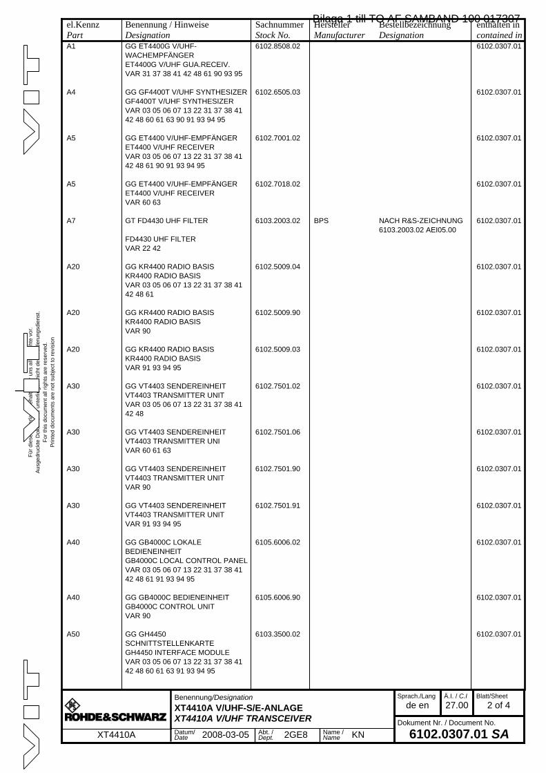
Für
die
se U
nter
lage
beh
alte
n w
ir un
s al
le R
echt
e vo
r.A
usge
druc
kte
Dok
umen
te u
nter
liege
n ni
cht d
em Ä
nder
ungs
dien
st.
For
this
doc
umen
t all
right
s ar
e re
serv
ed.
Prin
ted
docu
men
ts a
re n
ot s
ubje
ct to
rev
isio
n
_
el.KennzPart
Benennung / HinweiseDesignation
SachnummerStock No.
HerstellerManufacturer
BestellbezeichnungDesignation
enthalten incontained in
a
Benennung/Designation
XT4410A V/UHF-S/E-ANLAGEXT4410A V/UHF TRANSCEIVER
Sprach./Lang
de enÄ.I. / C.I
27.00Blatt/Sheet
2 of 4
Dokument Nr. / Document No.
6102.0307.01 SAXT4410A Datum/Date 2008-03-05 Abt. /
Dept. 2GE8 Name /Name KN
A1 GG ET4400G V/UHF-WACHEMPFÄNGER
6102.8508.02 6102.0307.01
ET4400G V/UHF GUA.RECEIV.VAR 31 37 38 41 42 48 61 90 93 95
A4 GG GF4400T V/UHF SYNTHESIZER 6102.6505.03 6102.0307.01GF4400T V/UHF SYNTHESIZERVAR 03 05 06 07 13 22 31 37 38 41 42 48 60 61 63 90 91 93 94 95
A5 GG ET4400 V/UHF-EMPFÄNGER 6102.7001.02 6102.0307.01ET4400 V/UHF RECEIVERVAR 03 05 06 07 13 22 31 37 38 41 42 48 61 90 91 93 94 95
A5 GG ET4400 V/UHF-EMPFÄNGER 6102.7018.02 6102.0307.01ET4400 V/UHF RECEIVERVAR 60 63
A7 GT FD4430 UHF FILTER 6103.2003.02 BPS NACH R&S-ZEICHNUNG 6103.2003.02 AEI05.00
6102.0307.01
FD4430 UHF FILTERVAR 22 42
A20 GG KR4400 RADIO BASIS 6102.5009.04 6102.0307.01KR4400 RADIO BASISVAR 03 05 06 07 13 22 31 37 38 41 42 48 61
A20 GG KR4400 RADIO BASIS 6102.5009.90 6102.0307.01KR4400 RADIO BASISVAR 90
A20 GG KR4400 RADIO BASIS 6102.5009.03 6102.0307.01KR4400 RADIO BASISVAR 91 93 94 95
A30 GG VT4403 SENDEREINHEIT 6102.7501.02 6102.0307.01VT4403 TRANSMITTER UNITVAR 03 05 06 07 13 22 31 37 38 41 42 48
A30 GG VT4403 SENDEREINHEIT 6102.7501.06 6102.0307.01VT4403 TRANSMITTER UNIVAR 60 61 63
A30 GG VT4403 SENDEREINHEIT 6102.7501.90 6102.0307.01VT4403 TRANSMITTER UNITVAR 90
A30 GG VT4403 SENDEREINHEIT 6102.7501.91 6102.0307.01VT4403 TRANSMITTER UNITVAR 91 93 94 95
A40 GG GB4000C LOKALE BEDIENEINHEIT
6105.6006.02 6102.0307.01
GB4000C LOCAL CONTROL PANELVAR 03 05 06 07 13 22 31 37 38 41 42 48 61 91 93 94 95
A40 GG GB4000C BEDIENEINHEIT 6105.6006.90 6102.0307.01GB4000C CONTROL UNITVAR 90
A50 GG GH4450 SCHNITTSTELLENKARTE
6103.3500.02 6102.0307.01
GH4450 INTERFACE MODULEVAR 03 05 06 07 13 22 31 37 38 41 42 48 60 61 63 91 93 94 95
Bilaga 1 till TO AF SAMBAND 100 017307
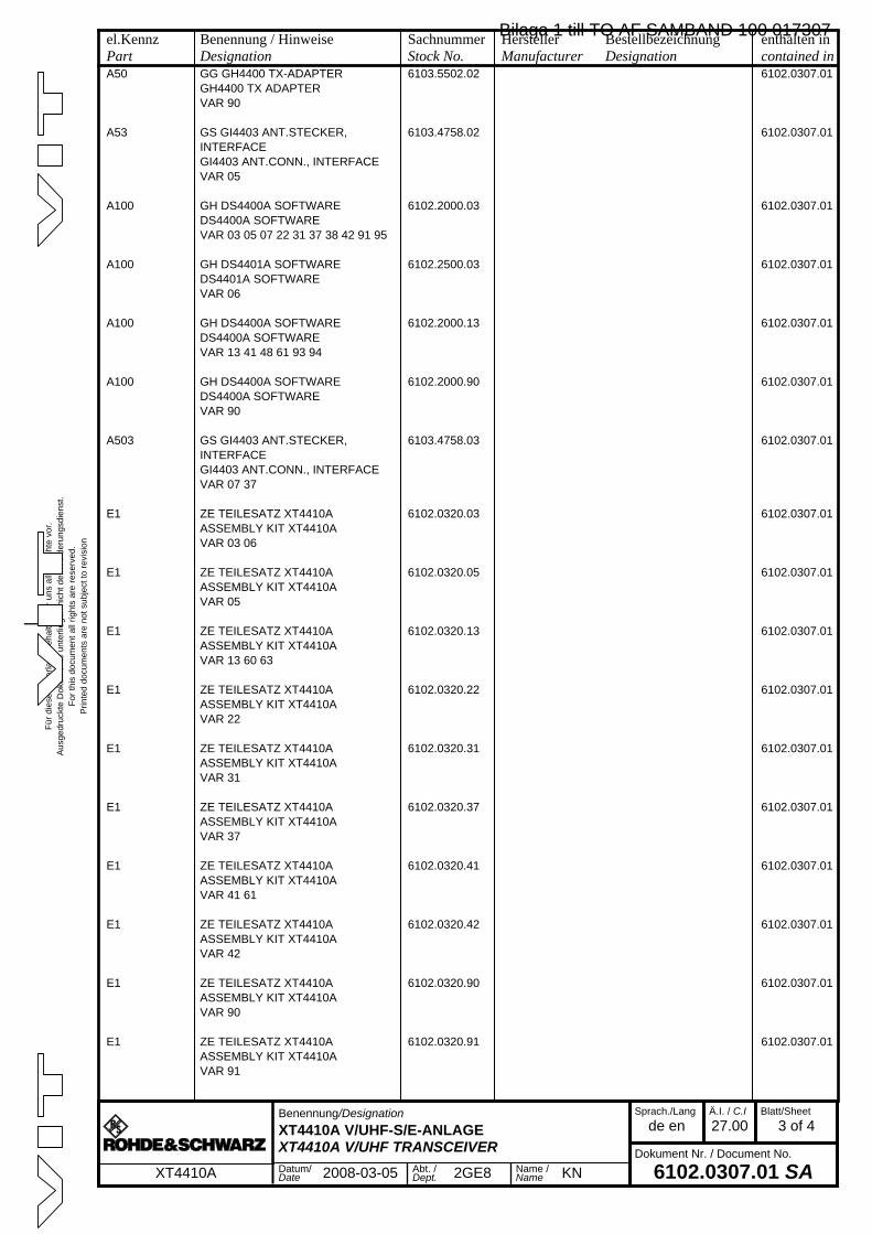
Für
die
se U
nter
lage
beh
alte
n w
ir un
s al
le R
echt
e vo
r.A
usge
druc
kte
Dok
umen
te u
nter
liege
n ni
cht d
em Ä
nder
ungs
dien
st.
For
this
doc
umen
t all
right
s ar
e re
serv
ed.
Prin
ted
docu
men
ts a
re n
ot s
ubje
ct to
rev
isio
n
_
el.KennzPart
Benennung / HinweiseDesignation
SachnummerStock No.
HerstellerManufacturer
BestellbezeichnungDesignation
enthalten incontained in
a
Benennung/Designation
XT4410A V/UHF-S/E-ANLAGEXT4410A V/UHF TRANSCEIVER
Sprach./Lang
de enÄ.I. / C.I
27.00Blatt/Sheet
3 of 4
Dokument Nr. / Document No.
6102.0307.01 SAXT4410A Datum/Date 2008-03-05 Abt. /
Dept. 2GE8 Name /Name KN
A50 GG GH4400 TX-ADAPTER 6103.5502.02 6102.0307.01GH4400 TX ADAPTERVAR 90
A53 GS GI4403 ANT.STECKER, INTERFACE
6103.4758.02 6102.0307.01
GI4403 ANT.CONN., INTERFACEVAR 05
A100 GH DS4400A SOFTWARE 6102.2000.03 6102.0307.01DS4400A SOFTWAREVAR 03 05 07 22 31 37 38 42 91 95
A100 GH DS4401A SOFTWARE 6102.2500.03 6102.0307.01DS4401A SOFTWAREVAR 06
A100 GH DS4400A SOFTWARE 6102.2000.13 6102.0307.01DS4400A SOFTWAREVAR 13 41 48 61 93 94
A100 GH DS4400A SOFTWARE 6102.2000.90 6102.0307.01DS4400A SOFTWAREVAR 90
A503 GS GI4403 ANT.STECKER, INTERFACE
6103.4758.03 6102.0307.01
GI4403 ANT.CONN., INTERFACEVAR 07 37
E1 ZE TEILESATZ XT4410A 6102.0320.03 6102.0307.01ASSEMBLY KIT XT4410AVAR 03 06
E1 ZE TEILESATZ XT4410A 6102.0320.05 6102.0307.01ASSEMBLY KIT XT4410AVAR 05
E1 ZE TEILESATZ XT4410A 6102.0320.13 6102.0307.01ASSEMBLY KIT XT4410AVAR 13 60 63
E1 ZE TEILESATZ XT4410A 6102.0320.22 6102.0307.01ASSEMBLY KIT XT4410AVAR 22
E1 ZE TEILESATZ XT4410A 6102.0320.31 6102.0307.01ASSEMBLY KIT XT4410AVAR 31
E1 ZE TEILESATZ XT4410A 6102.0320.37 6102.0307.01ASSEMBLY KIT XT4410AVAR 37
E1 ZE TEILESATZ XT4410A 6102.0320.41 6102.0307.01ASSEMBLY KIT XT4410AVAR 41 61
E1 ZE TEILESATZ XT4410A 6102.0320.42 6102.0307.01ASSEMBLY KIT XT4410AVAR 42
E1 ZE TEILESATZ XT4410A 6102.0320.90 6102.0307.01ASSEMBLY KIT XT4410AVAR 90
E1 ZE TEILESATZ XT4410A 6102.0320.91 6102.0307.01ASSEMBLY KIT XT4410AVAR 91
Bilaga 1 till TO AF SAMBAND 100 017307
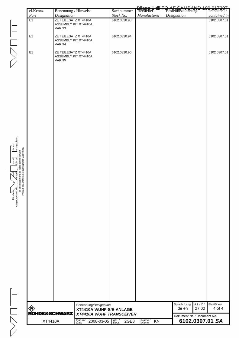
Für
die
se U
nter
lage
beh
alte
n w
ir un
s al
le R
echt
e vo
r.A
usge
druc
kte
Dok
umen
te u
nter
liege
n ni
cht d
em Ä
nder
ungs
dien
st.
For
this
doc
umen
t all
right
s ar
e re
serv
ed.
Prin
ted
docu
men
ts a
re n
ot s
ubje
ct to
rev
isio
n
_
el.KennzPart
Benennung / HinweiseDesignation
SachnummerStock No.
HerstellerManufacturer
BestellbezeichnungDesignation
enthalten incontained in
a
Benennung/Designation
XT4410A V/UHF-S/E-ANLAGEXT4410A V/UHF TRANSCEIVER
Sprach./Lang
de enÄ.I. / C.I
27.00Blatt/Sheet
4 of 4
Dokument Nr. / Document No.
6102.0307.01 SAXT4410A Datum/Date 2008-03-05 Abt. /
Dept. 2GE8 Name /Name KN
E1 ZE TEILESATZ XT4410A 6102.0320.93 6102.0307.01ASSEMBLY KIT XT4410AVAR 93
E1 ZE TEILESATZ XT4410A 6102.0320.94 6102.0307.01ASSEMBLY KIT XT4410AVAR 94
E1 ZE TEILESATZ XT4410A 6102.0320.95 6102.0307.01ASSEMBLY KIT XT4410AVAR 95
Bilaga 1 till TO AF SAMBAND 100 017307
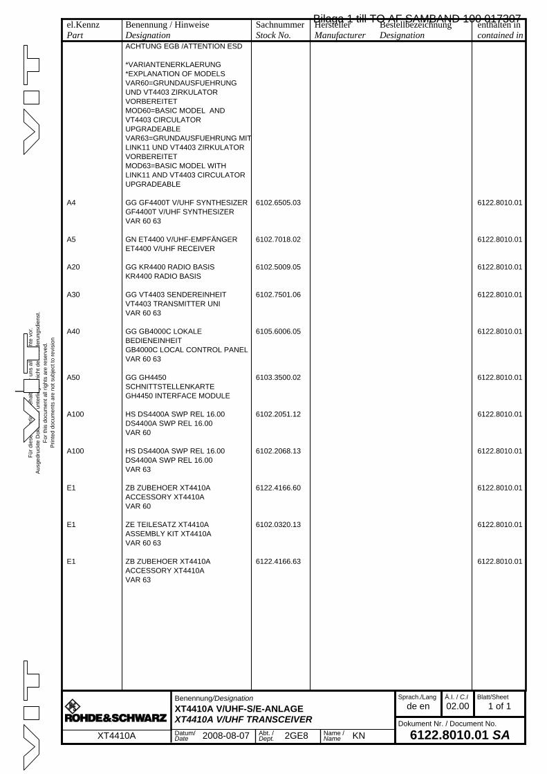
Für
die
se U
nter
lage
beh
alte
n w
ir un
s al
le R
echt
e vo
r.A
usge
druc
kte
Dok
umen
te u
nter
liege
n ni
cht d
em Ä
nder
ungs
dien
st.
For
this
doc
umen
t all
right
s ar
e re
serv
ed.
Prin
ted
docu
men
ts a
re n
ot s
ubje
ct to
rev
isio
n
_
el.KennzPart
Benennung / HinweiseDesignation
SachnummerStock No.
HerstellerManufacturer
BestellbezeichnungDesignation
enthalten incontained in
a
Benennung/Designation
XT4410A V/UHF-S/E-ANLAGEXT4410A V/UHF TRANSCEIVER
Sprach./Lang
de enÄ.I. / C.I
02.00Blatt/Sheet
1 of 1
Dokument Nr. / Document No.
6122.8010.01 SAXT4410A Datum/Date 2008-08-07 Abt. /
Dept. 2GE8 Name /Name KN
ACHTUNG EGB /ATTENTION ESD
*VARIANTENERKLAERUNG*EXPLANATION OF MODELSVAR60=GRUNDAUSFUEHRUNG UND VT4403 ZIRKULATOR VORBEREITETMOD60=BASIC MODEL AND VT4403 CIRCULATOR UPGRADEABLEVAR63=GRUNDAUSFUEHRUNG MIT LINK11 UND VT4403 ZIRKULATOR VORBEREITETMOD63=BASIC MODEL WITH LINK11 AND VT4403 CIRCULATOR UPGRADEABLE
A4 GG GF4400T V/UHF SYNTHESIZER 6102.6505.03 6122.8010.01GF4400T V/UHF SYNTHESIZERVAR 60 63
A5 GN ET4400 V/UHF-EMPFÄNGER 6102.7018.02 6122.8010.01ET4400 V/UHF RECEIVER
A20 GG KR4400 RADIO BASIS 6102.5009.05 6122.8010.01KR4400 RADIO BASIS
A30 GG VT4403 SENDEREINHEIT 6102.7501.06 6122.8010.01VT4403 TRANSMITTER UNIVAR 60 63
A40 GG GB4000C LOKALE BEDIENEINHEIT
6105.6006.05 6122.8010.01
GB4000C LOCAL CONTROL PANELVAR 60 63
A50 GG GH4450 SCHNITTSTELLENKARTE
6103.3500.02 6122.8010.01
GH4450 INTERFACE MODULE
A100 HS DS4400A SWP REL 16.00 6102.2051.12 6122.8010.01DS4400A SWP REL 16.00VAR 60
A100 HS DS4400A SWP REL 16.00 6102.2068.13 6122.8010.01DS4400A SWP REL 16.00VAR 63
E1 ZB ZUBEHOER XT4410A 6122.4166.60 6122.8010.01ACCESSORY XT4410AVAR 60
E1 ZE TEILESATZ XT4410A 6102.0320.13 6122.8010.01ASSEMBLY KIT XT4410AVAR 60 63
E1 ZB ZUBEHOER XT4410A 6122.4166.63 6122.8010.01ACCESSORY XT4410AVAR 63
Bilaga 1 till TO AF SAMBAND 100 017307

Bilaga 1 till TO AF SAMBAND 100 017307
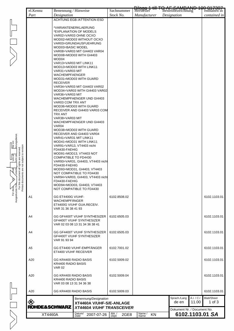
Für
die
se U
nter
lage
beh
alte
n w
ir un
s al
le R
echt
e vo
r.A
usge
druc
kte
Dok
umen
te u
nter
liege
n ni
cht d
em Ä
nder
ungs
dien
st.
For
this
doc
umen
t all
right
s ar
e re
serv
ed.
Prin
ted
docu
men
ts a
re n
ot s
ubje
ct to
rev
isio
n
_
el.KennzPart
Benennung / HinweiseDesignation
SachnummerStock No.
HerstellerManufacturer
BestellbezeichnungDesignation
enthalten incontained in
a
Benennung/Designation
XT4460A V/UHF-S/E-ANLAGEXT4460A V/UHF TRANSCEIVER
Sprach./Lang
de enÄ.I. / C.I
11.00Blatt/Sheet
1 of 3
Dokument Nr. / Document No.
6102.1103.01 SAXT4460A Datum/Date 2007-07-26 Abt. /
Dept. 2GE8 Name /Name KN
ACHTUNG EGB /ATTENTION ESD
*VARIANTENERKLAERUNG*EXPLANATION OF MODELSVAR02=VAR03 OHNE OCXOMOD02=MOD03 WITHOUT OCXOVAR03=GRUNDAUSFUEHRUNGMOD03=BASIC MODELVAR08=VAR03 MIT GI4403 VAR04MOD08=MOD03 WITH GI4403 MOD04VAR13=VAR03 MIT LINK11MOD13=MOD03 WITH LINK11VAR31=VAR03 MIT WACHEMPFAENGERMOD31=MOD03 WITH GUARD RECEIVERVAR34=VAR03 MIT GI4403 VAR02MOD34=VAR03 WITH GI4403 VAR02VAR36=VAR03 MIT WACHEMPFAENGER UND GI4403 VAR03 COM TRX ANTMOD36=MOD03 WITH GUARD RECEIVER AND GI4403 VAR03 COM TRX ANTVAR38=VAR03 MIT WACHEMPFAENGER UND GI4403 VAR04MOD38=MOD03 WITH GUARD RECEIVER AND GI4403 VAR04VAR41=VAR31 MIT LINK11MOD41=MOD31 WITH LINK11VAR91=VAR13, VT4403 nicht FD4430-FAEHIGMOD91=MOD13, VT4403 NOT COMPATIBLE TO FD4430VAR93=VAR31, GI4403, VT4403 nicht FD4430-FAEHIGMOD93=MOD31, GI4403, VT4403 NOT COMPATIBLE TO FD4430VAR94=VAR03, GI4403, VT4403 nicht FD4430-FAEHIGMOD94=MOD03, GI4403, VT4403 NOT COMPATIBLE TO FD4430
A1 GG ET4400G V/UHF-WACHEMPFÄNGER
6102.8508.02 6102.1103.01
ET4400G V/UHF GUA.RECEIV.VAR 31 36 38 41 93
A4 GG GF4400T V/UHF SYNTHESIZER 6102.6505.03 6102.1103.01GF4400T V/UHF SYNTHESIZERVAR 02 03 08 13 31 34 36 38 41
A4 GG GF4400T V/UHF SYNTHESIZER 6102.6505.03 6102.1103.01GF4400T V/UHF SYNTHESIZERVAR 91 93 94
A5 GG ET4400 V/UHF-EMPFÄNGER 6102.7001.02 6102.1103.01ET4400 V/UHF RECEIVER
A20 GG KR4400 RADIO BASIS 6102.5009.02 6102.1103.01KR4400 RADIO BASISVAR 02
A20 GG KR4400 RADIO BASIS 6102.5009.04 6102.1103.01KR4400 RADIO BASISVAR 03 08 13 31 34 36 38
A20 GG KR4400 RADIO BASIS 6102.5009.03 6102.1103.01
Bilaga 1 till TO AF SAMBAND 100 017307
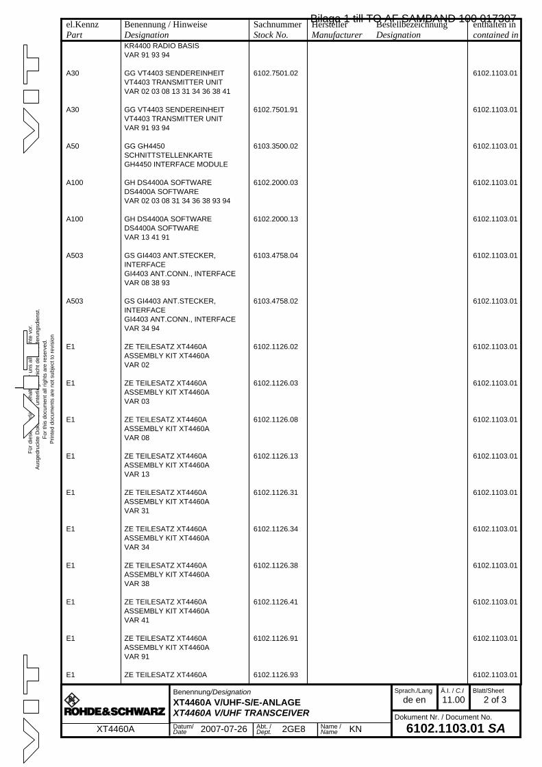
Für
die
se U
nter
lage
beh
alte
n w
ir un
s al
le R
echt
e vo
r.A
usge
druc
kte
Dok
umen
te u
nter
liege
n ni
cht d
em Ä
nder
ungs
dien
st.
For
this
doc
umen
t all
right
s ar
e re
serv
ed.
Prin
ted
docu
men
ts a
re n
ot s
ubje
ct to
rev
isio
n
_
el.KennzPart
Benennung / HinweiseDesignation
SachnummerStock No.
HerstellerManufacturer
BestellbezeichnungDesignation
enthalten incontained in
a
Benennung/Designation
XT4460A V/UHF-S/E-ANLAGEXT4460A V/UHF TRANSCEIVER
Sprach./Lang
de enÄ.I. / C.I
11.00Blatt/Sheet
2 of 3
Dokument Nr. / Document No.
6102.1103.01 SAXT4460A Datum/Date 2007-07-26 Abt. /
Dept. 2GE8 Name /Name KN
KR4400 RADIO BASISVAR 91 93 94
A30 GG VT4403 SENDEREINHEIT 6102.7501.02 6102.1103.01VT4403 TRANSMITTER UNITVAR 02 03 08 13 31 34 36 38 41
A30 GG VT4403 SENDEREINHEIT 6102.7501.91 6102.1103.01VT4403 TRANSMITTER UNITVAR 91 93 94
A50 GG GH4450 SCHNITTSTELLENKARTE
6103.3500.02 6102.1103.01
GH4450 INTERFACE MODULE
A100 GH DS4400A SOFTWARE 6102.2000.03 6102.1103.01DS4400A SOFTWAREVAR 02 03 08 31 34 36 38 93 94
A100 GH DS4400A SOFTWARE 6102.2000.13 6102.1103.01DS4400A SOFTWAREVAR 13 41 91
A503 GS GI4403 ANT.STECKER, INTERFACE
6103.4758.04 6102.1103.01
GI4403 ANT.CONN., INTERFACEVAR 08 38 93
A503 GS GI4403 ANT.STECKER, INTERFACE
6103.4758.02 6102.1103.01
GI4403 ANT.CONN., INTERFACEVAR 34 94
E1 ZE TEILESATZ XT4460A 6102.1126.02 6102.1103.01ASSEMBLY KIT XT4460AVAR 02
E1 ZE TEILESATZ XT4460A 6102.1126.03 6102.1103.01ASSEMBLY KIT XT4460AVAR 03
E1 ZE TEILESATZ XT4460A 6102.1126.08 6102.1103.01ASSEMBLY KIT XT4460AVAR 08
E1 ZE TEILESATZ XT4460A 6102.1126.13 6102.1103.01ASSEMBLY KIT XT4460AVAR 13
E1 ZE TEILESATZ XT4460A 6102.1126.31 6102.1103.01ASSEMBLY KIT XT4460AVAR 31
E1 ZE TEILESATZ XT4460A 6102.1126.34 6102.1103.01ASSEMBLY KIT XT4460AVAR 34
E1 ZE TEILESATZ XT4460A 6102.1126.38 6102.1103.01ASSEMBLY KIT XT4460AVAR 38
E1 ZE TEILESATZ XT4460A 6102.1126.41 6102.1103.01ASSEMBLY KIT XT4460AVAR 41
E1 ZE TEILESATZ XT4460A 6102.1126.91 6102.1103.01ASSEMBLY KIT XT4460AVAR 91
E1 ZE TEILESATZ XT4460A 6102.1126.93 6102.1103.01
Bilaga 1 till TO AF SAMBAND 100 017307
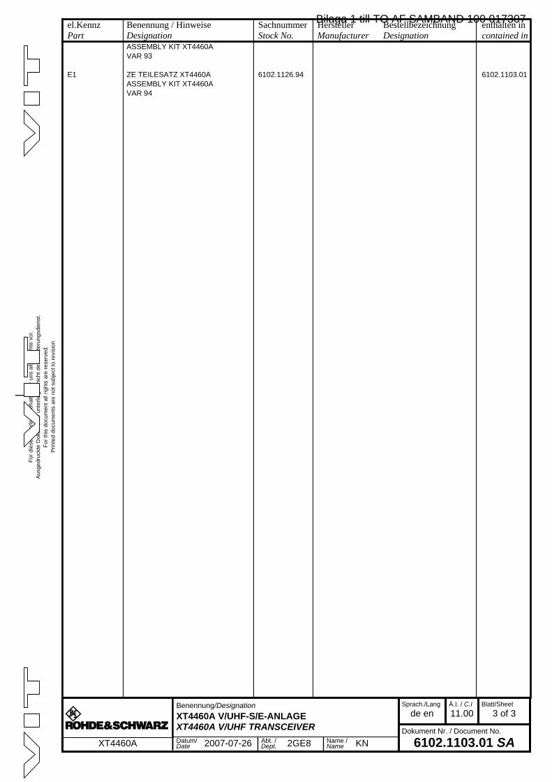
Für
die
se U
nter
lage
beh
alte
n w
ir un
s al
le R
echt
e vo
r.A
usge
druc
kte
Dok
umen
te u
nter
liege
n ni
cht d
em Ä
nder
ungs
dien
st.
For
this
doc
umen
t all
right
s ar
e re
serv
ed.
Prin
ted
docu
men
ts a
re n
ot s
ubje
ct to
rev
isio
n
_
el.KennzPart
Benennung / HinweiseDesignation
SachnummerStock No.
HerstellerManufacturer
BestellbezeichnungDesignation
enthalten incontained in
a
Benennung/Designation
XT4460A V/UHF-S/E-ANLAGEXT4460A V/UHF TRANSCEIVER
Sprach./Lang
de enÄ.I. / C.I
11.00Blatt/Sheet
3 of 3
Dokument Nr. / Document No.
6102.1103.01 SAXT4460A Datum/Date 2007-07-26 Abt. /
Dept. 2GE8 Name /Name KN
ASSEMBLY KIT XT4460AVAR 93
E1 ZE TEILESATZ XT4460A 6102.1126.94 6102.1103.01ASSEMBLY KIT XT4460AVAR 94
Bilaga 1 till TO AF SAMBAND 100 017307

Bilaga 1 till TO AF SAMBAND 100 017307
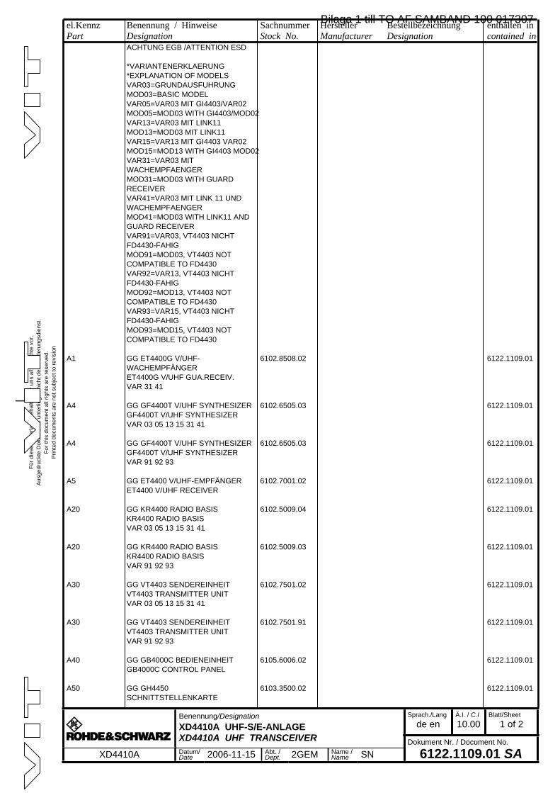
Für d
iese
Unt
erla
ge b
ehal
ten
wir
uns
alle
Rec
hte
vor.
Aus
gedr
uckt
e D
okum
ente
unt
erlie
gen
nich
t dem
Änd
erun
gsdi
enst
.Fo
r thi
s do
cum
ent a
ll rig
hts
are
rese
rved
.P
rinte
d do
cum
ents
are
not
sub
ject
to re
visi
on
_
el.KennzPart
Benennung / HinweiseDesignation
SachnummerStock No.
HerstellerManufacturer
BestellbezeichnungDesignation
enthalten incontained in
a
Benennung/DesignationXD4410A UHF-S/E-ANLAGEXD4410A UHF TRANSCEIVER
Sprach./Langde en
Ä.I. / C.I10.00
Blatt/Sheet1 of 2
Dokument Nr. / Document No.
6122.1109.01 SAXD4410A Datum/Date 2006-11-15 Abt. /
Dept. 2GEM Name /Name SN
ACHTUNG EGB /ATTENTION ESD
*VARIANTENERKLAERUNG*EXPLANATION OF MODELSVAR03=GRUNDAUSFUHRUNGMOD03=BASIC MODELVAR05=VAR03 MIT GI4403/VAR02MOD05=MOD03 WITH GI4403/MOD02VAR13=VAR03 MIT LINK11MOD13=MOD03 MIT LINK11VAR15=VAR13 MIT GI4403 VAR02MOD15=MOD13 WITH GI4403 MOD02VAR31=VAR03 MIT WACHEMPFAENGERMOD31=MOD03 WITH GUARD RECEIVERVAR41=VAR03 MIT LINK 11 UND WACHEMPFAENGERMOD41=MOD03 WITH LINK11 AND GUARD RECEIVERVAR91=VAR03, VT4403 NICHT FD4430-FAHIGMOD91=MOD03, VT4403 NOT COMPATIBLE TO FD4430VAR92=VAR13, VT4403 NICHT FD4430-FAHIGMOD92=MOD13, VT4403 NOT COMPATIBLE TO FD4430VAR93=VAR15, VT4403 NICHT FD4430-FAHIGMOD93=MOD15, VT4403 NOT COMPATIBLE TO FD4430
A1 GG ET4400G V/UHF-WACHEMPFÄNGER
6102.8508.02 6122.1109.01
ET4400G V/UHF GUA.RECEIV.VAR 31 41
A4 GG GF4400T V/UHF SYNTHESIZER 6102.6505.03 6122.1109.01GF4400T V/UHF SYNTHESIZERVAR 03 05 13 15 31 41
A4 GG GF4400T V/UHF SYNTHESIZER 6102.6505.03 6122.1109.01GF4400T V/UHF SYNTHESIZERVAR 91 92 93
A5 GG ET4400 V/UHF-EMPFÄNGER 6102.7001.02 6122.1109.01ET4400 V/UHF RECEIVER
A20 GG KR4400 RADIO BASIS 6102.5009.04 6122.1109.01KR4400 RADIO BASISVAR 03 05 13 15 31 41
A20 GG KR4400 RADIO BASIS 6102.5009.03 6122.1109.01KR4400 RADIO BASISVAR 91 92 93
A30 GG VT4403 SENDEREINHEIT 6102.7501.02 6122.1109.01VT4403 TRANSMITTER UNITVAR 03 05 13 15 31 41
A30 GG VT4403 SENDEREINHEIT 6102.7501.91 6122.1109.01VT4403 TRANSMITTER UNITVAR 91 92 93
A40 GG GB4000C BEDIENEINHEIT 6105.6006.02 6122.1109.01GB4000C CONTROL PANEL
A50 GG GH4450 SCHNITTSTELLENKARTE
6103.3500.02 6122.1109.01
Bilaga 1 till TO AF SAMBAND 100 017307
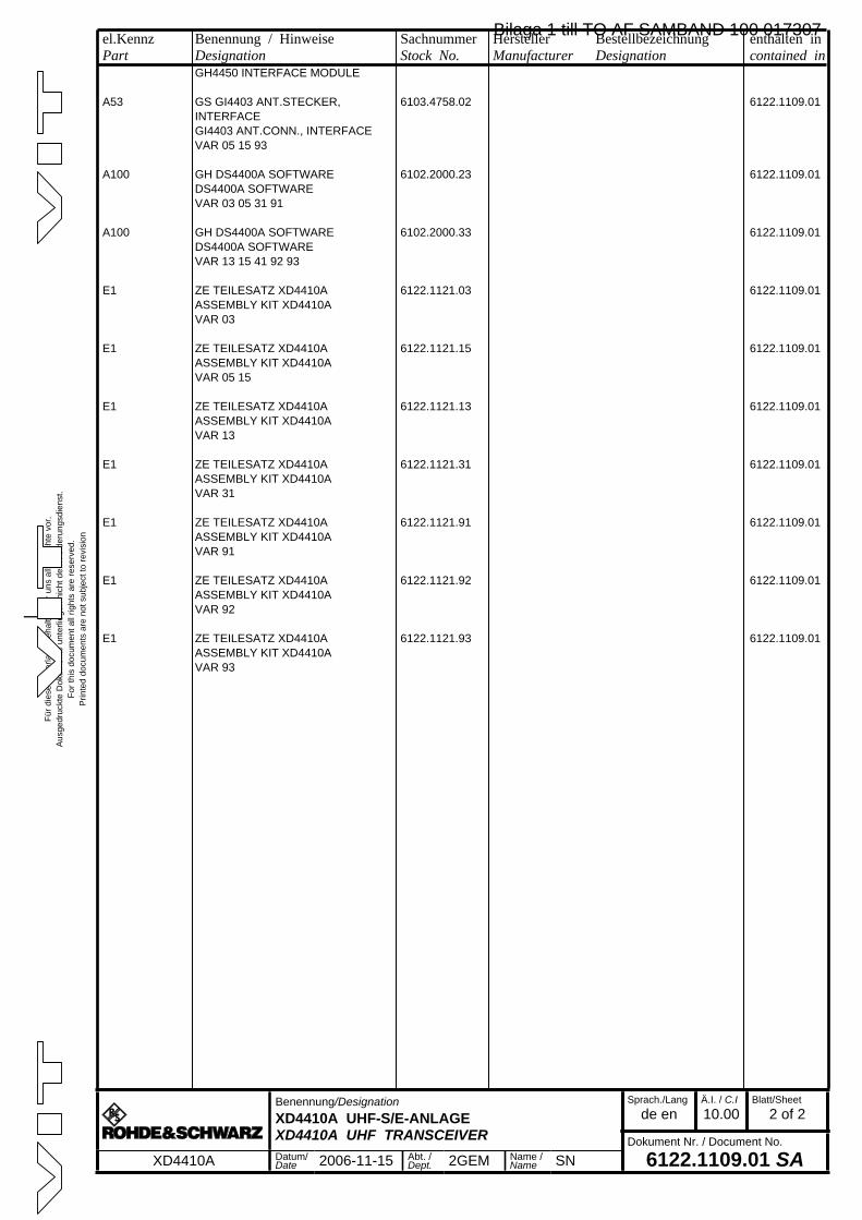
Für d
iese
Unt
erla
ge b
ehal
ten
wir
uns
alle
Rec
hte
vor.
Aus
gedr
uckt
e D
okum
ente
unt
erlie
gen
nich
t dem
Änd
erun
gsdi
enst
.Fo
r thi
s do
cum
ent a
ll rig
hts
are
rese
rved
.P
rinte
d do
cum
ents
are
not
sub
ject
to re
visi
on
_
el.KennzPart
Benennung / HinweiseDesignation
SachnummerStock No.
HerstellerManufacturer
BestellbezeichnungDesignation
enthalten incontained in
a
Benennung/DesignationXD4410A UHF-S/E-ANLAGEXD4410A UHF TRANSCEIVER
Sprach./Langde en
Ä.I. / C.I10.00
Blatt/Sheet2 of 2
Dokument Nr. / Document No.
6122.1109.01 SAXD4410A Datum/Date 2006-11-15 Abt. /
Dept. 2GEM Name /Name SN
GH4450 INTERFACE MODULE
A53 GS GI4403 ANT.STECKER, INTERFACE
6103.4758.02 6122.1109.01
GI4403 ANT.CONN., INTERFACEVAR 05 15 93
A100 GH DS4400A SOFTWARE 6102.2000.23 6122.1109.01DS4400A SOFTWAREVAR 03 05 31 91
A100 GH DS4400A SOFTWARE 6102.2000.33 6122.1109.01DS4400A SOFTWAREVAR 13 15 41 92 93
E1 ZE TEILESATZ XD4410A 6122.1121.03 6122.1109.01ASSEMBLY KIT XD4410AVAR 03
E1 ZE TEILESATZ XD4410A 6122.1121.15 6122.1109.01ASSEMBLY KIT XD4410AVAR 05 15
E1 ZE TEILESATZ XD4410A 6122.1121.13 6122.1109.01ASSEMBLY KIT XD4410AVAR 13
E1 ZE TEILESATZ XD4410A 6122.1121.31 6122.1109.01ASSEMBLY KIT XD4410AVAR 31
E1 ZE TEILESATZ XD4410A 6122.1121.91 6122.1109.01ASSEMBLY KIT XD4410AVAR 91
E1 ZE TEILESATZ XD4410A 6122.1121.92 6122.1109.01ASSEMBLY KIT XD4410AVAR 92
E1 ZE TEILESATZ XD4410A 6122.1121.93 6122.1109.01ASSEMBLY KIT XD4410AVAR 93
Bilaga 1 till TO AF SAMBAND 100 017307
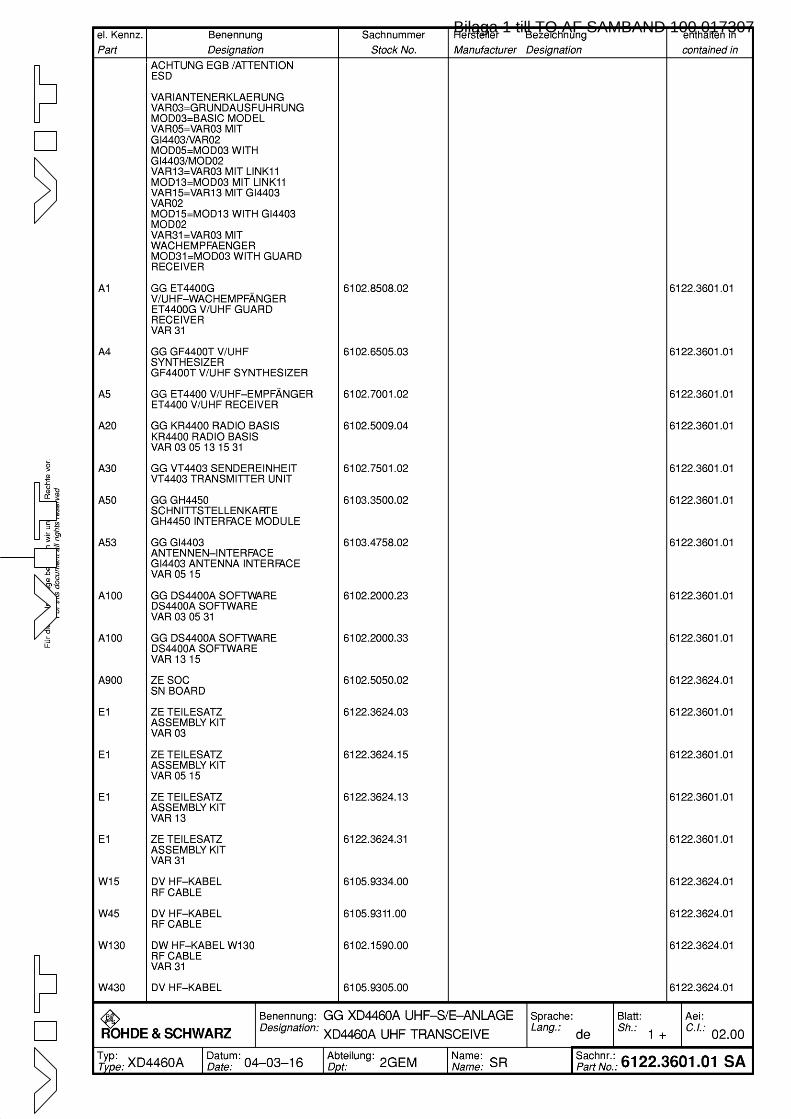
Bilaga 1 till TO AF SAMBAND 100 017307
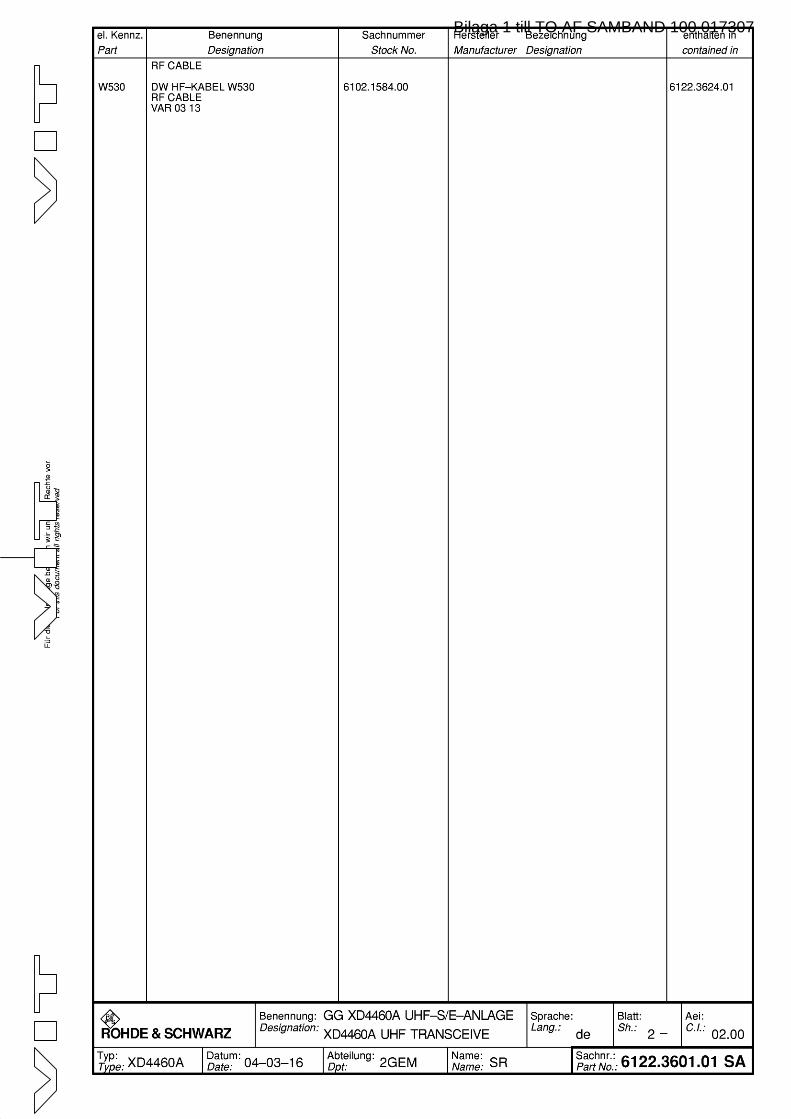
Bilaga 1 till TO AF SAMBAND 100 017307
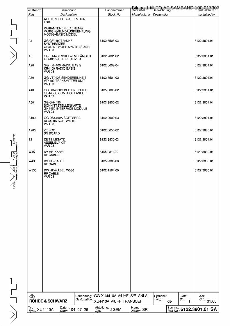
Bilaga 1 till TO AF SAMBAND 100 017307

Bilaga 1 till TO AF SAMBAND 100 017307
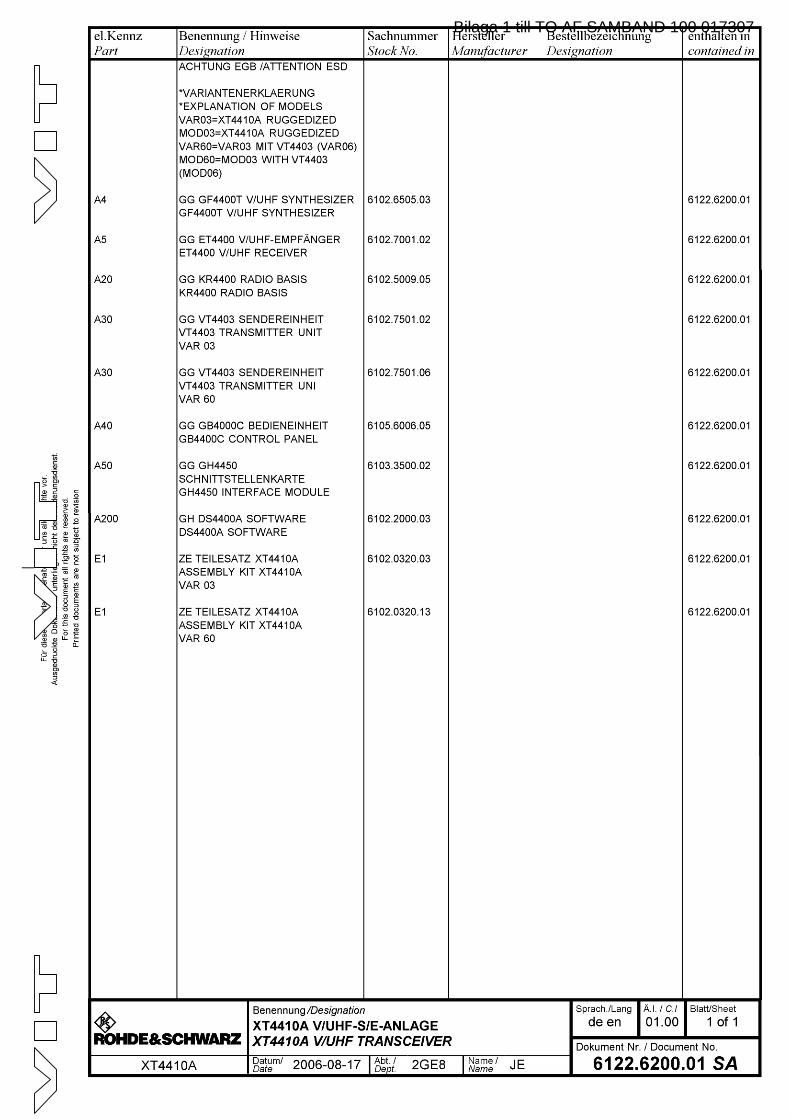
Bilaga 1 till TO AF SAMBAND 100 017307

Bilaga 1 till TO AF SAMBAND 100 017307

Digital Reprogrammable Software Radios ¸M3SRYour key to interoperability
Software download of new waveforms
High growth potential through P3I (preplanned product improvement)
Embedded hopping filter optionally available
High operational flexibility while on mission
Interoperability with existing radios according to international standards
Easy system integration Low life cycle costs
Dat
a sh
eet
Bilaga 1 till TO AF SAMBAND 100 017307
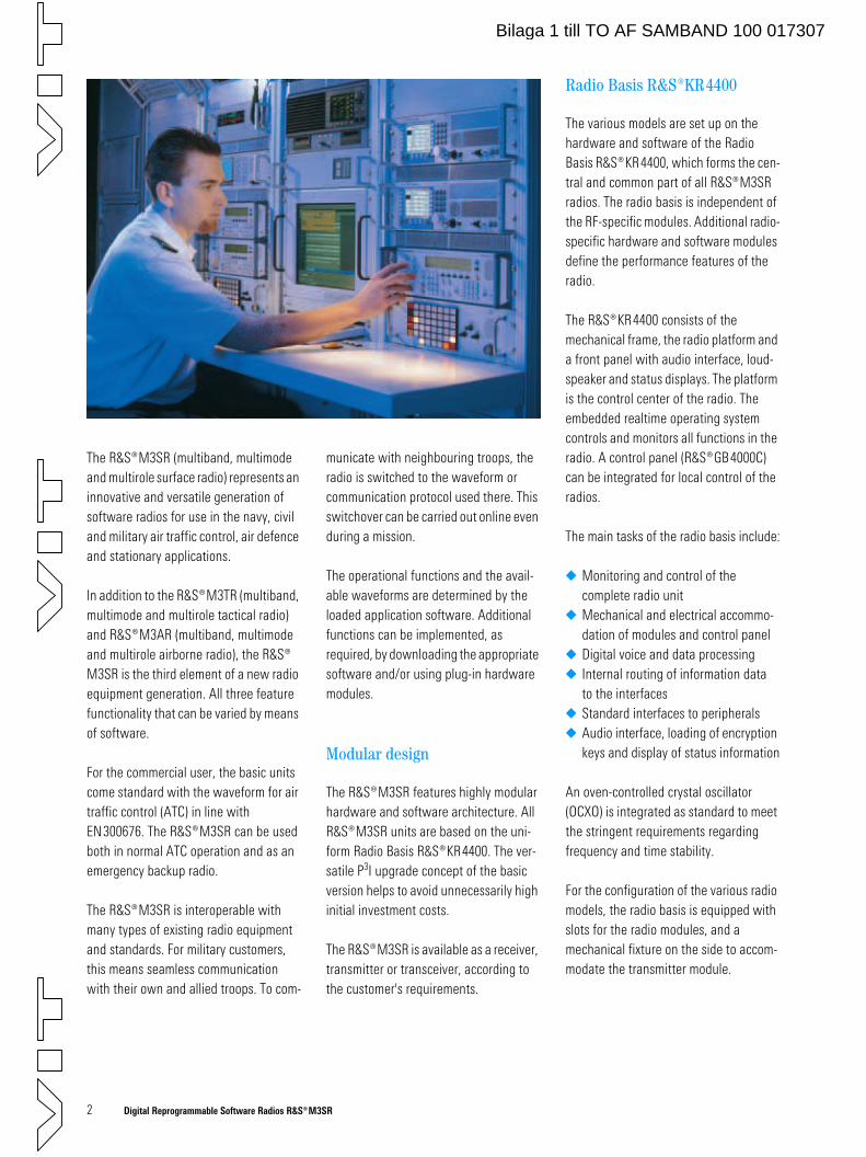
2 Digital Reprogrammable Software Radios ¸M3SR
The ¸M3SR (multiband, multimode and multirole surface radio) represents an innovative and versatile generation of software radios for use in the navy, civil and military air traffic control, air defence and stationary applications.
In addition to the M3TR (multiband, multimode and multirole tactical radio) and ¸M3AR (multiband, multimode and multirole airborne radio), the ¸ M3SR is the third element of a new radio equipment generation. All three feature functionality that can be varied by means of software.
For the commercial user, the basic units come standard with the waveform for air traffic control (ATC) in line with EN300676. The ¸M3SR can be used both in normal ATC operation and as an emergency backup radio.
The ¸M3SR is interoperable with many types of existing radio equipment and standards. For military customers, this means seamless communication with their own and allied troops. To com-
municate with neighbouring troops, the radio is switched to the waveform or communication protocol used there. This switchover can be carried out online even during a mission.
The operational functions and the avail-able waveforms are determined by the loaded application software. Additional functions can be implemented, as required, by downloading the appropriate software and/or using plug-in hardware modules.
Modular design
The ¸M3SR features highly modular hardware and software architecture. All ¸M3SR units are based on the uni-form Radio Basis ¸KR4400. The ver-satile P3I upgrade concept of the basic version helps to avoid unnecessarily high initial investment costs.
The M3SR is available as a receiver, transmitter or transceiver, according to the customer's requirements.
Radio Basis ¸KR4400
The various models are set up on the hardware and software of the Radio Basis KR4400, which forms the cen-tral and common part of all ¸M3SR radios. The radio basis is independent of the RF-specific modules. Additional radio-specific hardware and software modules define the performance features of the radio.
The ¸KR4400 consists of the mechanical frame, the radio platform and a front panel with audio interface, loud-speaker and status displays. The platform is the control center of the radio. The embedded realtime operating system controls and monitors all functions in the radio. A control panel (¸GB4000C) can be integrated for local control of the radios.
The main tasks of the radio basis include:
Monitoring and control of the complete radio unit
Mechanical and electrical accommo-dation of modules and control panel
Digital voice and data processing Internal routing of information data
to the interfaces Standard interfaces to peripherals Audio interface, loading of encryption
keys and display of status information
An oven-controlled crystal oscillator (OCXO) is integrated as standard to meet the stringent requirements regarding frequency and time stability.
For the configuration of the various radio models, the radio basis is equipped with slots for the radio modules, and a mechanical fixture on the side to accom-modate the transmitter module.
Bilaga 1 till TO AF SAMBAND 100 017307
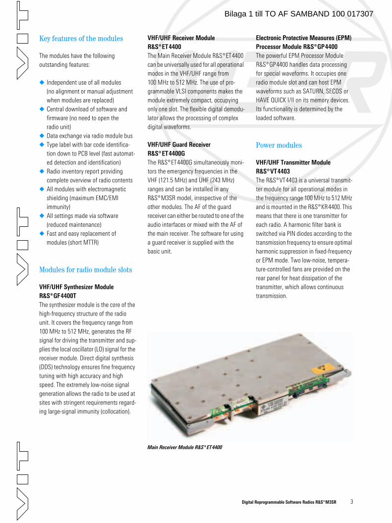
Digital Reprogrammable Software Radios ¸M3SR 3
Key features of the modules
The modules have the following outstanding features:
Independent use of all modules (no alignment or manual adjustment when modules are replaced)
Central download of software and firmware (no need to open the radio unit)
Data exchange via radio module bus Type label with bar code identifica-
tion down to PCB level (fast automat-ed detection and identification)
Radio inventory report providing complete overview of radio contents
All modules with electromagnetic shielding (maximum EMC/EMI immunity)
All settings made via software (reduced maintenance)
Fast and easy replacement of modules (short MTTR)
Modules for radio module slots
VHF/UHF Synthesizer Module
¸GF4400T
The synthesizer module is the core of the high-frequency structure of the radio unit. It covers the frequency range from 100 MHz to 512 MHz, generates the RF signal for driving the transmitter and sup-plies the local oscillator (LO) signal for the receiver module. Direct digital synthesis (DDS) technology ensures fine frequency tuning with high accuracy and high speed. The extremely low-noise signal generation allows the radio to be used at sites with stringent requirements regard-ing large-signal immunity (collocation).
VHF/UHF Receiver Module
¸ET4400
The Main Receiver Module ¸ET4400 can be universally used for all operational modes in the VHF/UHF range from 100 MHz to 512 MHz. The use of pro-grammable VLSI components makes the module extremely compact, occupying only one slot. The flexible digital demodu-lator allows the processing of complex digital waveforms.
VHF/UHF Guard Receiver
¸ET4400G
The ¸ET4400G simultaneously moni-tors the emergency frequencies in the VHF (121.5 MHz) and UHF (243 MHz) ranges and can be installed in any ¸M3SR model, irrespective of the other modules. The AF of the guard receiver can either be routed to one of the audio interfaces or mixed with the AF of the main receiver. The software for using a guard receiver is supplied with the basic unit.
Electronic Protective Measures (EPM)
Processor Module ¸GP4400
The powerful EPM Processor Module ¸GP4400 handles data processing for special waveforms. It occupies one radio module slot and can host EPM waveforms such as SATURN, SECOS or HAVE QUICK I/II on its memory devices. Its functionality is determined by the loaded software.
Power modules
VHF/UHF Transmitter Module
¸VT4403
The ¸VT4403 is a universal transmit-ter module for all operational modes in the frequency range 100 MHz to 512 MHz and is mounted in the KR4400. This means that there is one transmitter for each radio. A harmonic filter bank is switched via PIN diodes according to the transmission frequency to ensure optimal harmonic suppression in fixed-frequency or EPM mode. Two low-noise, tempera-ture-controlled fans are provided on the rear panel for heat dissipation of the transmitter, which allows continuous transmission.
Main Receiver Module ¸ET4400
Bilaga 1 till TO AF SAMBAND 100 017307
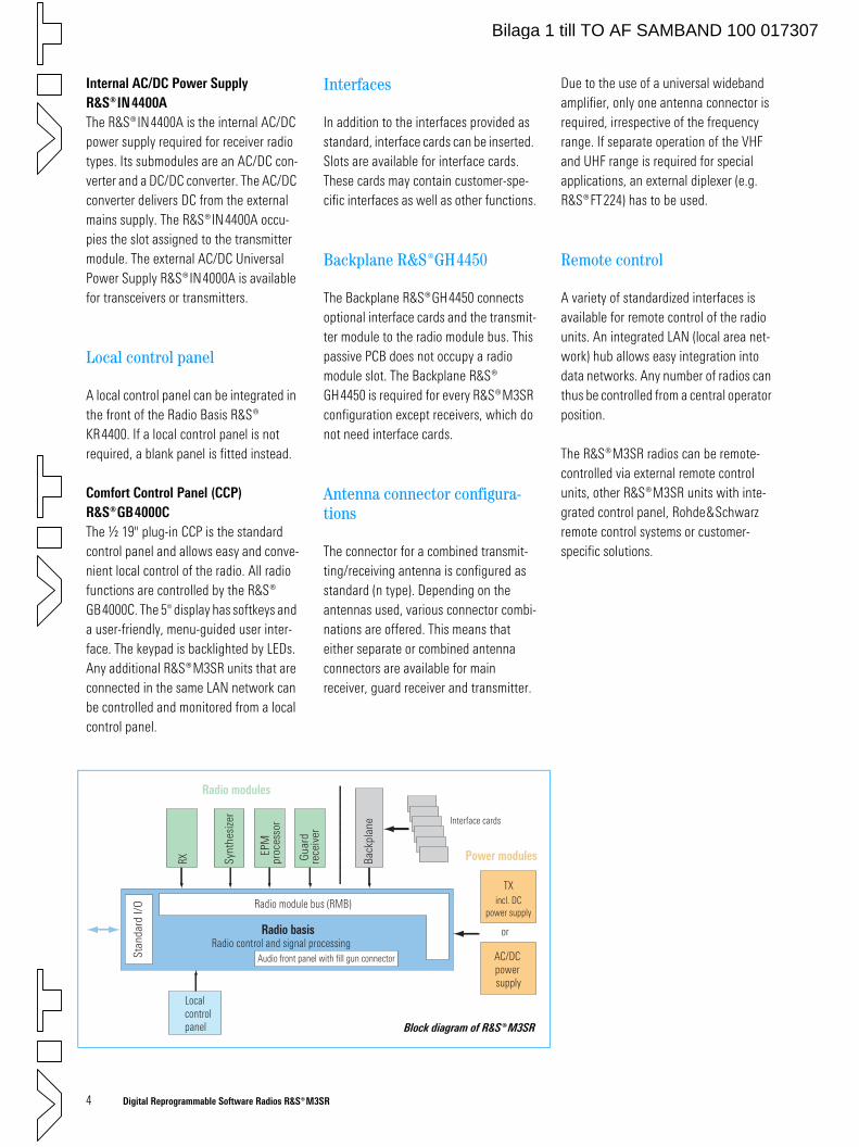
4 Digital Reprogrammable Software Radios ¸M3SR
or
Radio modules
Power modulesRX Synt
hesi
zer
EPM
pr
oces
sor
Radio basis
Radio module bus (RMB)
Stan
dard
I/O
Guar
dre
ceiv
er
incl. DCpower supply
AC/DC power supply
Radio control and signal processing
Localcontrolpanel
Back
plan
e
Audio front panel with fill gun connector
Interface cards
TX
Block diagram of ¸M3SR
Internal AC/DC Power Supply
¸IN4400A
The ¸IN4400A is the internal AC/DC power supply required for receiver radio types. Its submodules are an AC/DC con-verter and a DC/DC converter. The AC/DC converter delivers DC from the external mains supply. The ¸IN4400A occu-pies the slot assigned to the transmitter module. The external AC/DC Universal Power Supply ¸IN4000A is available for transceivers or transmitters.
Local control panel
A local control panel can be integrated in the front of the Radio Basis ¸ KR4400. If a local control panel is not required, a blank panel is fitted instead.
Comfort Control Panel (CCP)
¸GB4000C
The ½ 19" plug-in CCP is the standard control panel and allows easy and conve-nient local control of the radio. All radio functions are controlled by the ¸ GB4000C. The 5" display has softkeys and a user-friendly, menu-guided user inter-face. The keypad is backlighted by LEDs. Any additional ¸M3SR units that are connected in the same LAN network can be controlled and monitored from a local control panel.
Interfaces
In addition to the interfaces provided as standard, interface cards can be inserted. Slots are available for interface cards. These cards may contain customer-spe-cific interfaces as well as other functions.
Backplane ¸GH4450
The Backplane ¸GH4450 connects optional interface cards and the transmit-ter module to the radio module bus. This passive PCB does not occupy a radio module slot. The Backplane ¸ GH4450 is required for every M3SR configuration except receivers, which do not need interface cards.
Antenna connector configura-tions
The connector for a combined transmit-ting/receiving antenna is configured as standard (n type). Depending on the antennas used, various connector combi-nations are offered. This means that either separate or combined antenna connectors are available for main receiver, guard receiver and transmitter.
Due to the use of a universal wideband amplifier, only one antenna connector is required, irrespective of the frequency range. If separate operation of the VHF and UHF range is required for special applications, an external diplexer (e.g. ¸FT224) has to be used.
Remote control
A variety of standardized interfaces is available for remote control of the radio units. An integrated LAN (local area net-work) hub allows easy integration into data networks. Any number of radios can thus be controlled from a central operator position.
The ¸M3SR radios can be remote-controlled via external remote control units, other ¸M3SR units with inte-grated control panel, Rohde&Schwarz remote control systems or customer-specific solutions.
Bilaga 1 till TO AF SAMBAND 100 017307
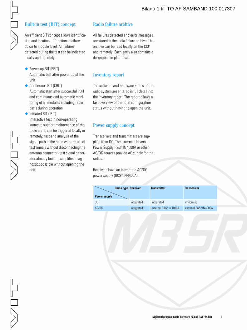
Digital Reprogrammable Software Radios ¸M3SR 5
Built-in test (BIT) concept
An efficient BIT concept allows identifica-tion and location of functional failures down to module level. All failures detected during the test can be indicated locally and remotely.
Power-up BIT (PBIT)Automatic test after power-up of the unit
Continuous BIT (CBIT)Automatic start after successful PBIT and continuous and automatic moni-toring of all modules including radio basis during operation
Initiated BIT (IBIT)Interactive test in non-operating status to support maintenance of the radio units; can be triggered locally or remotely; test and analysis of the signal path in the radio with the aid of test signals without disconnecting the antenna connector (test signal gener-ator already built in; simplified diag-nostics possible without opening the unit)
Radio failure archive
All failures detected and error messages are stored in the radio failure archive. The archive can be read locally on the CCP and remotely. Each entry also contains a description in plain text.
Inventory report
The software and hardware states of the radio system are entered in full detail into the inventory report. The report allows a fast overview of the total configuration status without having to open the unit.
Power supply concept
Transceivers and transmitters are sup-plied from DC. The external Universal Power Supply ¸IN4000A or other AC/DC sources provide AC supply for the radios.
Receivers have an integrated AC/DC power supply (¸IN4400A).
Radio type
Power supply
Receiver Transmitter Transceiver
DC integrated integrated integrated
AC/DC integrated external ¸IN4000A external ¸IN4000A
Bilaga 1 till TO AF SAMBAND 100 017307
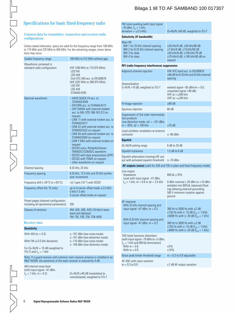
6 Digital Reprogrammable Software Radios ¸M3SR
Specifications for basic fixed-frequency radio
Common data for transmitter, transceiver and receiver radio configurations
Unless stated otherwise, specs are valid for the frequency range from 108 MHz to 174 MHz and 225 MHz to 400 MHz. For the remaining ranges, minor devia-tions may occur.
Usable frequency range 100 MHz to 512 MHz without gap
Waveforms contained instandard radio configuration VHF (108 MHz to 173.975 MHz):
LOS FM LOS AMCivil ATC AM acc. to EN300676
UHF (225 MHz to 399.975 MHz):LOS FM LOS AMSTANAG4205
Optional waveforms – HAVE QUICK I/II acc. toSTANAG4246
– SATURN acc. to STANAG4372– UHF DAMA with external modem
acc. to MIL-STD-188-181/2/3 on request
– LINK 11 with external modem acc. toSTANAG5511
– LINK 22 with external modem acc. toSTANAG5522 on request
– LINK 4A with external modem acc. toSTANAG5504 on request
– LINK Y Mk2 with external modem onrequest
– SECOS voice, Rohde&SchwarzTRANSEC/COMSEC waveform
– SECOS with data preprocessor (DPP)– SECOS with TDMA on request– other waveforms on request
Channel spacing 8.33 kHz, 25 kHz
Frequency spacing 8.33 kHz, 12.5 kHz and 25 kHz synthe-sizer increments
Frequency drift (–20°C to +55°C) <0.1 ppm (10–7) with OCXO
Frequency offset (for TX only) up to 4-carrier offset mode ±2.5 kHz/5 kHz/7.5 kHz5-carrier offset mode on request
Preset pages (channel configuration, including all operational parameters) 200
Classes of emission AM: A3E, A9E, AXX (16 kbit/s base-band and diphase)FM: F3E, F9E, FSK, FSK-MSK
Receiver data
Sensitivity
With AM (m = 0.3)
With FM (±3.5 kHz deviation)
For (S+N)/N = 10 dB (weighted to ITU-T) and fm = 1 kHz
≤–107 dBm (low-noise mode)≤–101 dBm (low-distortion mode)≤–110 dBm (low-noise mode)≤–104 dBm (low-distortion mode)
Note: If a guard receiver with common main receiver antenna is installed in an ¸M3SR, the sensitivity of the main receiver is reduced by 4 dB.
AM internal noise level (with input signal –47 dBm, fm = 1 kHz, m = 0.3) (S+N)/N ≥40 dB (modulated-to-
unmodulated), weighted to ITU-T
FM noise quieting (with input signal –70 dBm, fm = 1 kHz; deviation = ±3.5 kHz) (S+N)/N ≥40 dB, weighted to ITU-T
Selectivity (IF bandwidth)
Main RXBW 1 for 25 kHz channel spacingBW 2 for 8.33 kHz channel spacingBW 3 for dataBW 4 for data
≥26 kHz/6 dB, ≤50 kHz/80 dB≥7 kHz/6 dB, ≤13 kHz/60 dB≥50 kHz/6 dB, ≤150 kHz/70 dB≥70 kHz/6 dB, ≤140 kHz/60 dB on request
RFI (radio frequency interference) suppression
Adjacent-channel rejection VHF ATC band acc. to EN300676≥60 dB for 8.33 kHz and 25 kHz channel spacing
DesensitizationS+N/N >10 dB, weighted to ITU-T wanted signal –95 dBm/m = 0.6,
unwanted signal +80 dBcVHF at >±200 kHzUHF at >±200 kHz
IF/image rejection ≥80 dB
Spurious rejection 80 dB
Suppression of 3rd order intermodula-tion productsLow-distortion mode, ref = –101 dBm, m = 30%, ∆f = 100 kHz ≥70 dB
Local oscillator reradiation at antenna connector ≤–90 dBm
Squelch
(S+N)/N setting range 6 dB to 20 dB
Squelch hysteresis 1.5 dB to 6 dB
Squelch attenuation (muting) (AF out-put with activated squelch threshold) ≤–70 dBm
AF outputs (voice) (valid for A3E and F3E in plain and fixed-frequency mode)
Line outputImpedanceLevel with input signal –47 dBm, fm = 1 kHz, m = 0.6 or ∆f = 3.5 kHz
600 Ω ±10%
0 dBm nominal (–20 dBm to +10 dBm settable) into 600 Ω, balanced (float-ing) allowing external grounding;500 V minimum isolation against ground
AF responseWith 25 kHz channel spacing andinput signal –47 dBm, m = 0.3
With 8.33 kHz channel spacing andinput signal –47 dBm, m = 0.3
300 Hz to 3500 Hz with ±2 dB ≤150 Hz with ≤–15 dB (fref = 1 kHz) ≥5000 Hz with ≤–20 dB (fref = 1 kHz)
300 Hz to 3000 Hz with ±2 dB ≤150 Hz with ≤–15 dB (fref = 1 kHz) ≥4000 Hz with ≤–20 dB (fref = 1 kHz)
THD (total harmonic distortion) (with input signal –79 dBm to +3 dBm, fm = 1 kHz and 600 Ω termination)
With m = 0.6With m = 0.9
≤5%≤10%
Noise peak limiter threshold range m = 0.3 to 0.9 adjustable
AF AGC with input variation m = 0.3 to 0.9 ≤1 dB AF output variation
Bilaga 1 till TO AF SAMBAND 100 017307
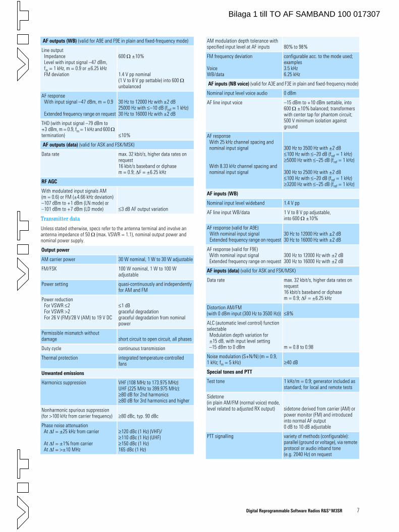
Digital Reprogrammable Software Radios ¸M3SR 7
AF outputs (WB) (valid for A9E and F9E in plain and fixed-frequency mode)
Line outputImpedanceLevel with input signal –47 dBm, fm = 1 kHz, m = 0.9 or ±6.25 kHz FM deviation
600 Ω ±10%
1.4 V pp nominal (1 V to 8 V pp settable) into 600 Ω unbalanced
AF responseWith input signal –47 dBm, m = 0.9
Extended frequency range on request
30 Hz to 12000 Hz with ±2 dB 25000 Hz with ≤–10 dB (fref = 1 kHz) 30 Hz to 16000 Hz with ±2 dB
THD (with input signal –79 dBm to +3 dBm, m = 0.9, fm = 1 kHz and 600 Ω termination) ≤10%
AF outputs (data) (valid for ASK and FSK/MSK)
Data rate max. 32 kbit/s, higher data rates on request16 kbit/s baseband or diphasem = 0.9; ∆F = ±6.25 kHz
RF AGC
With modulated input signals AM (m = 0.6) or FM (±4.66 kHz deviation)–107 dBm to +1 dBm (LN mode) or–101 dBm to +7 dBm (LD mode) ≤3 dB AF output variation
Transmitter data
Unless stated otherwise, specs refer to the antenna terminal and involve an antenna impedance of 50 Ω (max. VSWR = 1.1), nominal output power and nominal power supply.
Output power
AM carrier power 30 W nominal, 1 W to 30 W adjustable
FM/FSK 100 W nominal, 1 W to 100 W adjustable
Power setting quasi-continuously and independently for AM and FM
Power reductionFor VSWR ≤2For VSWR >2For 26 V (FM)/28 V (AM) to 19 V DC
≤1 dBgraceful degradationgraceful degradation from nominal power
Permissible mismatch without damage short circuit to open circuit, all phases
Duty cycle continuous transmission
Thermal protection integrated temperature-controlled fans
Unwanted emissions
Harmonics suppression VHF (108 MHz to 173.975 MHz)UHF (225 MHz to 399.975 MHz): ≥80 dB for 2nd harmonics≥80 dB for 3rd harmonics and higher
Nonharmonic spurious suppression (for >100 kHz from carrier frequency) ≥80 dBc, typ. 90 dBc
Phase noise attenuationAt ∆f = ±25 kHz from carrier
At ∆f = ±1% from carrierAt ∆f = >±10 MHz
≥120 dBc (1 Hz) (VHF)/≥110 dBc (1 Hz) (UHF)≥150 dBc (1 Hz)165 dBc (1 Hz)
AM modulation depth tolerance with specified input level at AF inputs 80% to 98%
FM frequency deviation
VoiceWB/data
configurable acc. to the mode used; examples3.5 kHz6.25 kHz
AF inputs (NB voice) (valid for A3E and F3E in plain and fixed-frequency mode)
Nominal input level voice audio 0 dBm
AF line input voice –15 dBm to +10 dBm settable, into 600 Ω ±10% balanced; transformers with center tap for phantom circuit;500 V minimum isolation against ground
AF responseWith 25 kHz channel spacing and nominal input signal
With 8.33 kHz channel spacing and nominal input signal
300 Hz to 3500 Hz with ±2 dB ≤100 Hz with ≤–20 dB (fref = 1 kHz) ≥5000 Hz with ≤–25 dB (fref = 1 kHz)
300 Hz to 2500 Hz with ±2 dB ≤100 Hz with ≤–20 dB (fref = 1 kHz) ≥3200 Hz with ≤–25 dB (fref = 1 kHz)
AF inputs (WB)
Nominal input level wideband 1.4 V pp
AF line input WB/data 1 V to 8 V pp adjustable, into 600 Ω ±10%
AF response (valid for A9E)With nominal input signalExtended frequency range on request
30 Hz to 12000 Hz with ±2 dB 30 Hz to 16000 Hz with ±2 dB
AF response (valid for F9E)With nominal input signalExtended frequency range on request
300 Hz to 12000 Hz with ±2 dB 300 Hz to 16000 Hz with ±2 dB
AF inputs (data) (valid for ASK and FSK/MSK)
Data rate max. 32 kbit/s, higher data rates on request16 kbit/s baseband or diphasem = 0.9; ∆F = ±6.25 kHz
Distortion AM/FM (with 0 dBm input (300 Hz to 3500 Hz)) ≤8%
ALC (automatic level control) function selectable
Modulation depth variation for ±15 dB, with input level setting –15 dBm to 0 dBm m = 0.8 to 0.98
Noise modulation (S+N/N) (m = 0.9, 1 kHz; fm = 5 kHz) ≥40 dB
Special tones and PTT
Test tone 1 kHz/m = 0.9; generator included as standard; for local and remote tests
Sidetone (in plain AM/FM (normal voice) mode, level related to adjusted RX output) sidetone derived from carrier (AM) or
power monitor (FM) and introduced into normal AF output0 dB to 10 dB adjustable
PTT signalling variety of methods (configurable): parallel (ground or voltage), via remote protocol or audio inband tone (e.g. 2040 Hz) on request
Bilaga 1 till TO AF SAMBAND 100 017307
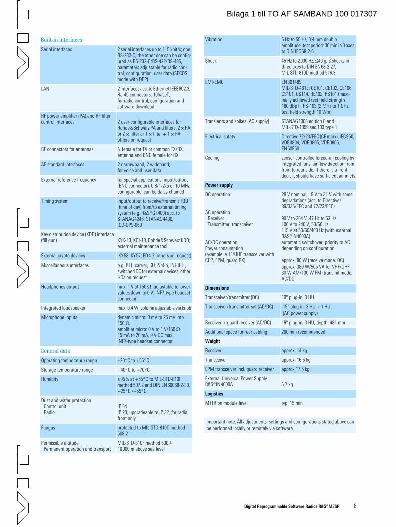
Digital Reprogrammable Software Radios ¸M3SR 8
Built-in interfaces
Serial interfaces 2 serial interfaces up to 115 kbit/s; one RS-232-C, the other one can be config-ured as RS-232-C/RS-422/RS-485, parameters adjustable for radio con-trol, configuration, user data (SECOS mode with DPP)
LAN 2 interfaces acc. to Ethernet IEEE802.3, RJ-45 connectors, 10baseT;for radio control, configuration and software download
RF power amplifier (PA) and RF filter control interfaces 2 user-configurable interfaces for
Rohde&Schwarz PA and filters: 2 × PA or 2 × filter or 1 × filter + 1 × PA; others on request
RF connectors for antennas N female for TX or common TX/RX antenna and BNC female for RX
AF standard interfaces 2 narrowband, 2 wideband;for voice and user data
External reference frequency for special applications; input/output (BNC connector): 0.8/1/2/5 or 10 MHz configurable, can be daisy-chained
Timing system input/output to receive/transmit TOD (time of day) from/to external timing system (e.g. ¸GT400) acc. to STANAG4246, STANAG4430, ICD-GPS-060
Key distribution device (KDD) interface (fill gun) KYK-13, KOI-18, Rohde&Schwarz KDD;
external maintenance tool
External crypto devices KY58, KY57, ED4-2 (others on request)
Miscellaneous interfaces e.g. PTT, carrier, SQ, NoGo, INHIBIT, switched DC for external devices; other I/Os on request
Headphones output max. 1 V at 150 Ω (adjustable to lower values down to 0 V), NF7-type headset connector
Integrated loudspeaker max. 0.4 W, volume adjustable via knob
Microphone inputs dynamic micro: 0 mV to 25 mV into 150 Ωamplifier micro: 0 V to 1 V/150 Ω, 15 mA to 20 mA, 9 V DC max., NF7-type headset connector
General data
Operating temperature range –20°C to +55°C
Storage temperature range –40°C to +70°C
Humidity ≤95% at +55°C to MIL-STD-810F method 507.2 and DIN EN60068-2-30, +25°C /+55°C
Dust and water protectionControl unitRadio
IP 54IP 20, upgradeable to IP 32, for radio front only
Fungus protected to MIL-STD-810C method 508.2
Permissible altitudePermanent operation and transport
MIL-STD-810F method 500.410000 m above sea level
Vibration 5 Hz to 55 Hz, 0.4 mm double amplitude, test period: 30 min in 3 axes to DIN IEC68-2-6
Shock 45 Hz to 2000 Hz, ≤40 g, 3 shocks in three axes to DIN EN68-2-27, MIL-STD-810D method 516.3
EMI/EMC EN301489MIL-STD-461E: CE101, CE102, CE106, CS101, CS114, RE102, RS101 (maxi-mally achieved test field strength 160 dBpT), RS-103 (2 MHz to 1 GHz, test field strength 10 V/m)
Transients and spikes (AC supply) STANAG1008 edition 8 and MIL-STD-1399 sec.103 type 1
Electrical safety Directive 72/23/EEC (CE mark), IEC950, VDE0804, VDE0805, VDE0866, EN60950
Cooling sensor-controlled forced-air cooling by integrated fans, air flow direction from front to rear side; if there is a front door, it should have sufficient air inlets
Power supply
DC operation
AC operationReceiverTransmitter, transceiver
AC/DC operationPower consumption (example: VHF/UHF transceiver with CCP, EPM, guard RX)
28 V nominal, 19 V to 31 V with some degradations (acc. to Directives 89/336/EEC and 72/23/EEC)
90 V to 264 V, 47 Hz to 63 Hz100 V to 240 V, 50/60 Hz115 V at 50/60/400 Hz (with external ¸IN4000A)automatic switchover; priority to ACdepending on configuration
approx. 80 W (receive mode, DC)approx. 380 W/505 VA for VHF/UHF 30 W AM/100 W FM (transmit mode, AC/DC)
Dimensions
Transceiver/transmitter (DC) 19" plug-in, 3 HU
Transceiver/transmitter set (AC/DC) 19" plug-in, 3 HU + 1 HU (AC power supply)
Receiver + guard receiver (AC/DC) 19" plug-in, 3 HU, depth: 481 mm
Additional space for rear cabling 200 mm recommended
Weight
Receiver approx. 14 kg
Transceiver approx. 16.5 kg
EPM transceiver incl. guard receiver approx.17.5 kg
External Universal Power Supply ¸IN4000A 5.7 kg
Logistics
MTTR on module level typ. 15 min
Important note: All adjustments, settings and configurations stated above can be performed locally or remotely via software.
Bilaga 1 till TO AF SAMBAND 100 017307
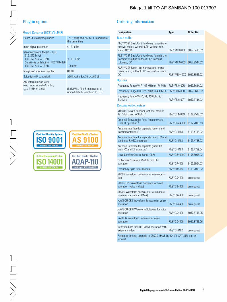
Digital Reprogrammable Software Radios ¸M3SR 9
Plug-in option
Guard Receiver ¸ET4400G
Guard (distress) frequencies 121.5 MHz and 243 MHz in parallel at the same time
Input signal protection ≤+21 dBm
Sensitivity (with AM (m = 0.3), 121.5/243 MHz)
ITU-T S+N/N = 10 dBSensitivity with built-in ¸FD4430ITU-T S+N/N = 12 dB
≤–101 dBm
–99 dBm
Image and spurious rejection 80 dB
Selectivity (IF bandwidth) ≥30 kHz/6 dB, ≤75 kHz/60 dB
AM internal noise level (with input signal –47 dBm, fm = 1 kHz, m = 0.8) (S+N)/N = 40 dB (modulated-to-
unmodulated), weighted to ITU-T
Ordering information
Designation Type Order No.
Basic radio
¸M3SR Basic Unit Hardware for split-site receiver radios, without CCP, without soft-ware, AC/DC ¸MR4400E 6057.8496.02
¸M3SR Basic Unit Hardware for split-site transmitter radios; without CCP, without software, DC ¸MR4400S 6057.8544.02
¸M3SR Basic Unit Hardware for trans-ceiver radios, without CCP, without software, DC ¸MR4400X 6057.8596.02
Options
Frequency Range VHF, 108 MHz to 174 MHz ¸FR4400U 6057.8644.02
Frequency Range UHF, 225 MHz to 400 MHz ¸FR4400D 6057.8696.02
Frequency Range VHF/UHF, 100 MHz to 512 MHz ¸FR4400T 6057.8744.02
Recommended extras
VHF/UHF Guard Receiver, optional module, 121.5 MHz and 243 MHz1) ¸ET4400G 6102.8508.02
Optional Software for fixed frequency and LINK 11 operation1) ¸DS4400A 6102.2000.13
Antenna Interface for separate receive and transmit antennas1) ¸GI4403 6103.4758.02
Antenna Interface for separate guard RX and combined RX/TX antennas1) ¸GI4403 6103.4758.03
Antenna Interface for separate guard RX, main RX and TX antennas1) ¸GI4403 6103.4758.04
Local Comfort Control Panel (CCP) ¸GB4000C 6105.6006.02
Protection Processor Module for EPM operation ¸GP4400 6102.9504.03
Frequency Agile Filter Module ¸FD4430 6103.2003.02
SECOS Waveform Software for voice opera-tion ¸GS4400 on request
SECOS DPP Waveform Software for voice operation (voice + data) ¸GS4400 on request
SECOS Waveform Software for voice opera-tion (voice + data + TDMA) ¸GS4400 on request
HAVE QUICK I Waveform Software for voice operation ¸GS4400 on request
HAVE QUICK II Waveform Software for voice operation ¸GS4400 6057.8796.05
SATURN Waveform Software for voice operation ¸GS4400 6057.8796.06
Interface Card for UHF DAMA operation with external modem ¸GI4402 on request
Packages for later upgrade to SECOS, HAVE QUICK I/II, SATURN, etc, on request.
Certified Quality System
ISO 9001DQS REG. NO 1954 QM
Certified Environmental System
ISO 14001DQS REG. NO 1954 UM
AQAP-110Audit report GP Q2-NO 96.07
Certified Quality System
AS 9100DQS REG. NO 1954 AS
Certified Quality System
Bilaga 1 till TO AF SAMBAND 100 017307
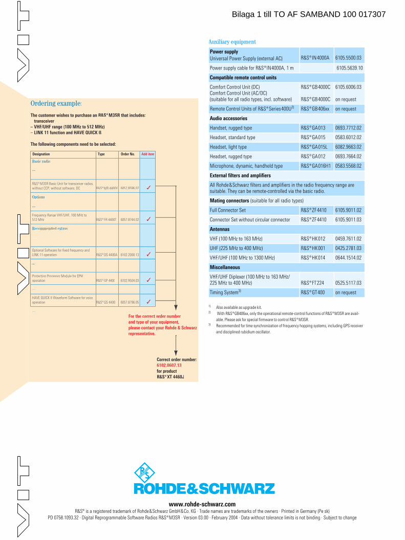
www.rohde-schwarz.com R&S® is a registered trademark of Rohde&Schwarz GmbH&Co. KG · Trade names are trademarks of the owners · Printed in Germany (Pe sk)
PD 0758.1093.32 · Digital Reprogrammable Software Radios ¸M3SR · Version 03.00 · February 2004 · Data without tolerance limits is not binding · Subject to change
Correct order number:
6102.0607.13
for product
¸XT 4460J
For the correct order number
and type of your equipment,
please contact your Rohde & Schwarz
representative.
Basic radio
...
¸MR 4400X
Options
...
Recommended extras
...
6102.2000.13
...
6102.9504.03
...
6057.8796.05
...
¸M3SR Basic Unit for transceiver radios,without CCP, without software, DC
¸FR 4400TFrequency Range VHF/UHF, 100 MHz to512 MHz
¸DS 4400AOptional Software for fixed frequency andLINK 11 operation
¸GP 4400Protection Processor Module for EPMoperation
¸GS 4400HAVE QUICK II Waveform Software for voiceoperation
Designation Type Order No. Add item
Ordering example:
The customer wishes to purchase an ¸M3SR that includes:
– transceiver
– VHF/UHF range (100 MHz to 512 MHz)
– LINK 11 function and HAVE QUICK II.
The following components need to be selected:
6057.8596.02
6057.8744.02
Auxiliary equipment
Power supply
Universal Power Supply (external AC) ¸IN4000A 6105.5500.03
Power supply cable for ¸IN4000A, 1 m 6105.5639.10
Compatible remote control units
Comfort Control Unit (DC)Comfort Control Unit (AC/DC) (suitable for all radio types, incl. software)
¸GB4000C
¸GB4000C
6105.6006.03
on request
Remote Control Units of ¸Series400U2) ¸GB406xx on request
Audio accessories
Handset, rugged type ¸GA013 0693.7712.02
Headset, standard type ¸GA015 0583.6012.02
Headset, light type ¸GA015L 6082.9663.02
Headset, rugged type ¸GA012 0693.7664.02
Microphone, dynamic, handheld type ¸GA016H1 0583.5568.02
External filters and amplifiers
All Rohde&Schwarz filters and amplifiers in the radio frequency range are suitable. They can be remote-controlled via the basic radio.
Mating connectors (suitable for all radio types)
Full Connector Set ¸ZF4410 6105.9011.02
Connector Set without circular connector ¸ZF4410 6105.9011.03
Antennas
VHF (100 MHz to 163 MHz) ¸HK012 0459.7611.02
UHF (225 MHz to 400 MHz) ¸HK001 0425.2781.03
VHF/UHF (100 MHz to 1300 MHz) ¸HK014 0644.1514.02
Miscellaneous
VHF/UHF Diplexer (100 MHz to 163 MHz/225 MHz to 400 MHz) ¸FT224 0525.5117.03
Timing System3) ¸GT400 on request
1) Also available as upgrade kit.2) With GB406xx, only the operational remote-control functions of M3SR are avail-
able. Please ask for special firmware to control M3SR.3) Recommended for time synchronization of frequency hopping systems, including GPS receiver
and disciplined rubidium oscillator.
Bilaga 1 till TO AF SAMBAND 100 017307
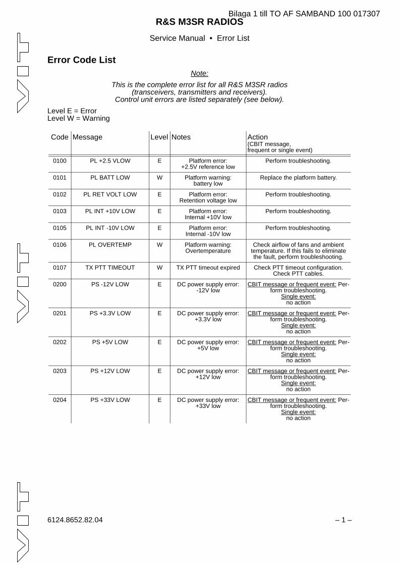
R&S M3SR RADIOSService Manual • Error List
6124.8652.82.04 – 1 –
Error Code ListNote:
This is the complete error list for all R&S M3SR radios(transceivers, transmitters and receivers).
Control unit errors are listed separately (see below).Level E = ErrorLevel W = Warning
Code Message Level Notes Action(CBIT message,frequent or single event)
0100 PL +2.5 VLOW E Platform error:+2.5V reference low
Perform troubleshooting.
0101 PL BATT LOW W Platform warning:battery low
Replace the platform battery.
0102 PL RET VOLT LOW E Platform error:Retention voltage low
Perform troubleshooting.
0103 PL INT +10V LOW E Platform error:Internal +10V low
Perform troubleshooting.
0105 PL INT -10V LOW E Platform error:Internal -10V low
Perform troubleshooting.
0106 PL OVERTEMP W Platform warning:Overtemperature
Check airflow of fans and ambient temperature. If this fails to eliminate the fault, perform troubleshooting.
0107 TX PTT TIMEOUT W TX PTT timeout expired Check PTT timeout configuration. Check PTT cables.
0200 PS -12V LOW E DC power supply error:-12V low
CBIT message or frequent event: Per-form troubleshooting.
Single event:no action
0201 PS +3.3V LOW E DC power supply error:+3.3V low
CBIT message or frequent event: Per-form troubleshooting.
Single event:no action
0202 PS +5V LOW E DC power supply error:+5V low
CBIT message or frequent event: Per-form troubleshooting.
Single event:no action
0203 PS +12V LOW E DC power supply error:+12V low
CBIT message or frequent event: Per-form troubleshooting.
Single event:no action
0204 PS +33V LOW E DC power supply error:+33V low
CBIT message or frequent event: Per-form troubleshooting.
Single event:no action
Bilaga 1 till TO AF SAMBAND 100 017307
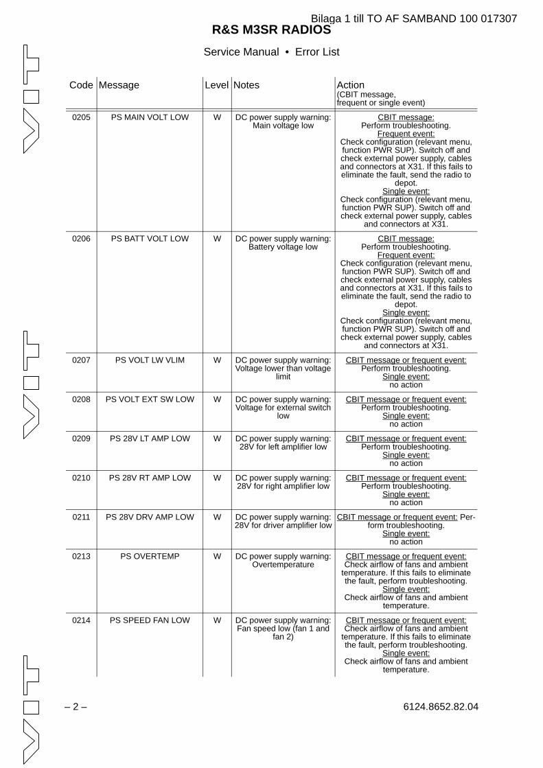
R&S M3SR RADIOSService Manual • Error List
– 2 – 6124.8652.82.04
0205 PS MAIN VOLT LOW W DC power supply warning:Main voltage low
CBIT message:Perform troubleshooting.
Frequent event:Check configuration (relevant menu, function PWR SUP). Switch off and check external power supply, cables and connectors at X31. If this fails to eliminate the fault, send the radio to
depot.Single event:
Check configuration (relevant menu, function PWR SUP). Switch off and check external power supply, cables
and connectors at X31.
0206 PS BATT VOLT LOW W DC power supply warning:Battery voltage low
CBIT message:Perform troubleshooting.
Frequent event:Check configuration (relevant menu, function PWR SUP). Switch off and check external power supply, cables and connectors at X31. If this fails to eliminate the fault, send the radio to
depot.Single event:
Check configuration (relevant menu, function PWR SUP). Switch off and check external power supply, cables
and connectors at X31.
0207 PS VOLT LW VLIM W DC power supply warning:Voltage lower than voltage
limit
CBIT message or frequent event:Perform troubleshooting.
Single event:no action
0208 PS VOLT EXT SW LOW W DC power supply warning:Voltage for external switch
low
CBIT message or frequent event:Perform troubleshooting.
Single event:no action
0209 PS 28V LT AMP LOW W DC power supply warning:28V for left amplifier low
CBIT message or frequent event:Perform troubleshooting.
Single event:no action
0210 PS 28V RT AMP LOW W DC power supply warning:28V for right amplifier low
CBIT message or frequent event:Perform troubleshooting.
Single event:no action
0211 PS 28V DRV AMP LOW W DC power supply warning:28V for driver amplifier low
CBIT message or frequent event: Per-form troubleshooting.
Single event:no action
0213 PS OVERTEMP W DC power supply warning:Overtemperature
CBIT message or frequent event:Check airflow of fans and ambient
temperature. If this fails to eliminate the fault, perform troubleshooting.
Single event:Check airflow of fans and ambient
temperature.
0214 PS SPEED FAN LOW W DC power supply warning:Fan speed low (fan 1 and
fan 2)
CBIT message or frequent event:Check airflow of fans and ambient
temperature. If this fails to eliminate the fault, perform troubleshooting.
Single event:Check airflow of fans and ambient
temperature.
Code Message Level Notes Action(CBIT message,frequent or single event)
Bilaga 1 till TO AF SAMBAND 100 017307
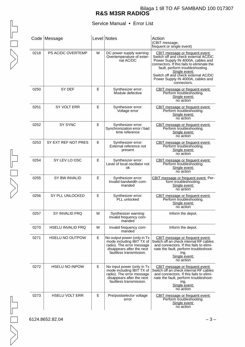
R&S M3SR RADIOSService Manual • Error List
6124.8652.82.04 – 3 –
0218 PS AC/DC OVERTEMP W DC power supply warning:Overtemperature of exter-
nal AC/DC
CBIT message or frequent event:Switch off and check external AC/DC Power Supply IN 4000A, cables and
connectors. If this fails to eliminate the fault, perform troubleshooting.
Single event:Switch off and check external AC/DC Power Supply IN 4000A, cables and
connectors.
0250 SY DEF E Synthesizer error:Module defective
CBIT message or frequent event:Perform troubleshooting.
Single event:no action
0251 SY VOLT ERR E Synthesizer error:Voltage error
CBIT message or frequent event:Perform troubleshooting.
Single event:no action
0252 SY SYNC E Synthesizer error:Synchronization error / bad
time reference
CBIT message or frequent event:Perform troubleshooting.
Single event:no action
0253 SY EXT REF NOT PRES E Synthesizer error:External reference not
present
CBIT message or frequent event:Perform troubleshooting.
Single event:no action
0254 SY LEV LO OSC E Synthesizer error:Level of local oscillator not
ok
CBIT message or frequent event:Perform troubleshooting.
Single event:no action
0255 SY BW INVALID E Synthesizer error:Invalid bandwidth com-
manded
CBIT message or frequent event: Per-form troubleshooting.
Single event:no action
0256 SY PLL UNLOCKED E Synthesizer error:PLL unlocked
CBIT message or frequent event:Perform troubleshooting.
Single event:no action
0257 SY INVALID FRQ W Synthesizer warning:Invalid frequency com-
manded
Inform the depot.
0270 HSELU INVALID FRQ W Invalid frequency com-manded
Inform the depot.
0271 HSELU NO OUTPOW E No output power (only in Tx mode including IBIT TX of radio). The error message disappears after the next
faultless transmission.
CBIT message or frequent event:Switch off an check internal RF cables
and connectors. If this fails to elimi-nate the fault, perform troubleshoot-
ing.Single event:
no action
0272 HSELU NO INPOW E No input power (only in Tx mode including IBIT TX of radio). The error message disappears after the next
faultless transmission.
CBIT message or frequent event:Switch off an check internal RF cables
and connectors. If this fails to elimi-nate the fault, perform troubleshoot-
ing.Single event:
no action
0273 HSELU VOLT ERR E Pre/postselector voltage error
CBIT message or frequent event:Perform troubleshooting.
Single event:no action
Code Message Level Notes Action(CBIT message,frequent or single event)
Bilaga 1 till TO AF SAMBAND 100 017307
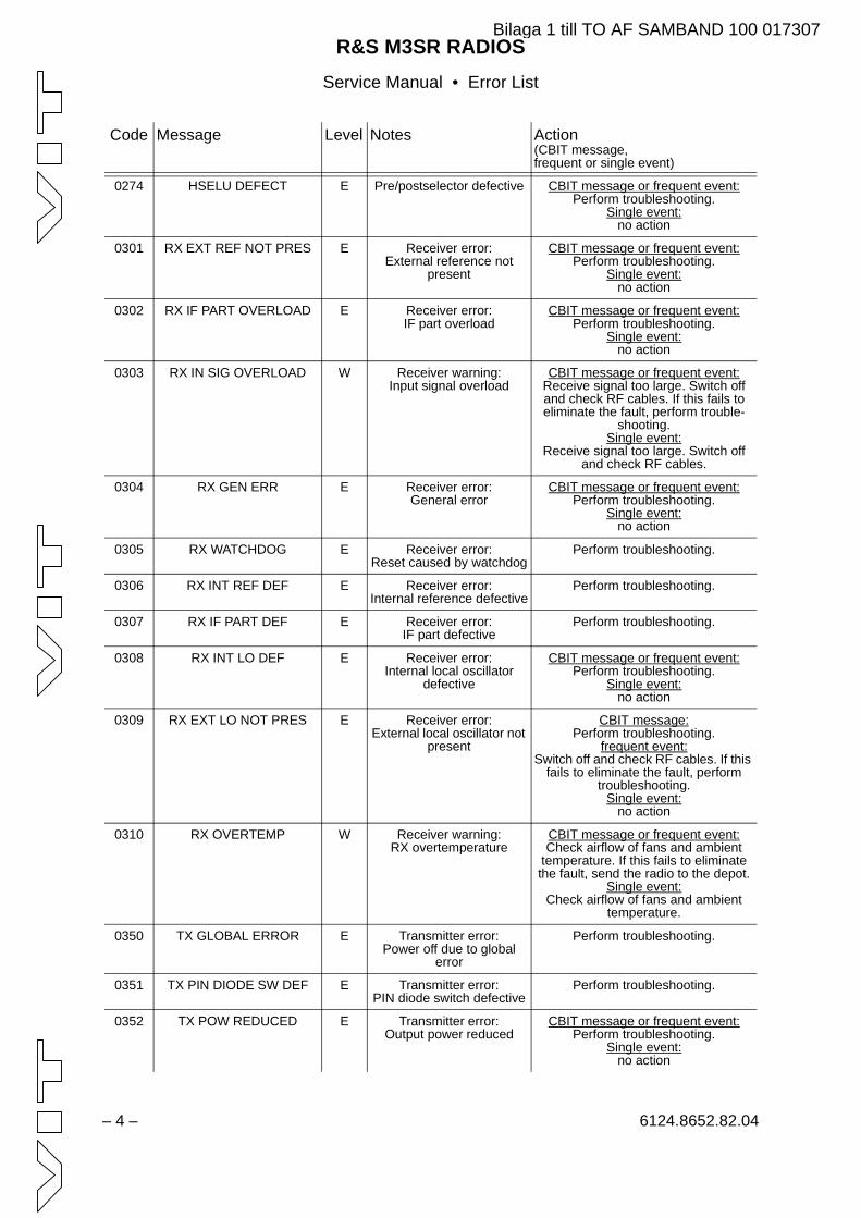
R&S M3SR RADIOSService Manual • Error List
– 4 – 6124.8652.82.04
0274 HSELU DEFECT E Pre/postselector defective CBIT message or frequent event:Perform troubleshooting.
Single event:no action
0301 RX EXT REF NOT PRES E Receiver error:External reference not
present
CBIT message or frequent event:Perform troubleshooting.
Single event:no action
0302 RX IF PART OVERLOAD E Receiver error:IF part overload
CBIT message or frequent event:Perform troubleshooting.
Single event:no action
0303 RX IN SIG OVERLOAD W Receiver warning:Input signal overload
CBIT message or frequent event:Receive signal too large. Switch off and check RF cables. If this fails to eliminate the fault, perform trouble-
shooting.Single event:
Receive signal too large. Switch off and check RF cables.
0304 RX GEN ERR E Receiver error:General error
CBIT message or frequent event:Perform troubleshooting.
Single event:no action
0305 RX WATCHDOG E Receiver error:Reset caused by watchdog
Perform troubleshooting.
0306 RX INT REF DEF E Receiver error:Internal reference defective
Perform troubleshooting.
0307 RX IF PART DEF E Receiver error:IF part defective
Perform troubleshooting.
0308 RX INT LO DEF E Receiver error:Internal local oscillator
defective
CBIT message or frequent event:Perform troubleshooting.
Single event:no action
0309 RX EXT LO NOT PRES E Receiver error:External local oscillator not
present
CBIT message:Perform troubleshooting.
frequent event:Switch off and check RF cables. If this
fails to eliminate the fault, perform troubleshooting.
Single event:no action
0310 RX OVERTEMP W Receiver warning:RX overtemperature
CBIT message or frequent event:Check airflow of fans and ambient
temperature. If this fails to eliminate the fault, send the radio to the depot.
Single event:Check airflow of fans and ambient
temperature.
0350 TX GLOBAL ERROR E Transmitter error:Power off due to global
error
Perform troubleshooting.
0351 TX PIN DIODE SW DEF E Transmitter error:PIN diode switch defective
Perform troubleshooting.
0352 TX POW REDUCED E Transmitter error:Output power reduced
CBIT message or frequent event:Perform troubleshooting.
Single event:no action
Code Message Level Notes Action(CBIT message,frequent or single event)
Bilaga 1 till TO AF SAMBAND 100 017307
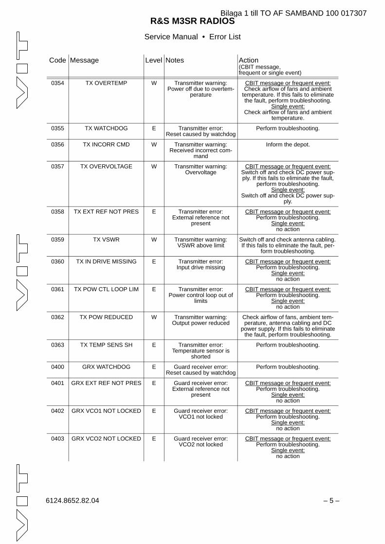
R&S M3SR RADIOSService Manual • Error List
6124.8652.82.04 – 5 –
0354 TX OVERTEMP W Transmitter warning:Power off due to overtem-
perature
CBIT message or frequent event:Check airflow of fans and ambient
temperature. If this fails to eliminate the fault, perform troubleshooting.
Single event:Check airflow of fans and ambient
temperature.
0355 TX WATCHDOG E Transmitter error:Reset caused by watchdog
Perform troubleshooting.
0356 TX INCORR CMD W Transmitter warning:Received incorrect com-
mand
Inform the depot.
0357 TX OVERVOLTAGE W Transmitter warning:Overvoltage
CBIT message or frequent event:Switch off and check DC power sup-ply. If this fails to eliminate the fault,
perform troubleshooting.Single event:
Switch off and check DC power sup-ply.
0358 TX EXT REF NOT PRES E Transmitter error:External reference not
present
CBIT message or frequent event:Perform troubleshooting.
Single event:no action
0359 TX VSWR W Transmitter warning:VSWR above limit
Switch off and check antenna cabling. If this fails to eliminate the fault, per-
form troubleshooting.
0360 TX IN DRIVE MISSING E Transmitter error:Input drive missing
CBIT message or frequent event:Perform troubleshooting.
Single event:no action
0361 TX POW CTL LOOP LIM E Transmitter error:Power control loop out of
limits
CBIT message or frequent event:Perform troubleshooting.
Single event:no action
0362 TX POW REDUCED W Transmitter warning:Output power reduced
Check airflow of fans, ambient tem-perature, antenna cabling and DC
power supply. If this fails to eliminate the fault, perform troubleshooting.
0363 TX TEMP SENS SH E Transmitter error:Temperature sensor is
shorted
Perform troubleshooting.
0400 GRX WATCHDOG E Guard receiver error:Reset caused by watchdog
Perform troubleshooting.
0401 GRX EXT REF NOT PRES E Guard receiver error:External reference not
present
CBIT message or frequent event:Perform troubleshooting.
Single event:no action
0402 GRX VCO1 NOT LOCKED E Guard receiver error:VCO1 not locked
CBIT message or frequent event:Perform troubleshooting.
Single event:no action
0403 GRX VCO2 NOT LOCKED E Guard receiver error:VCO2 not locked
CBIT message or frequent event:Perform troubleshooting.
Single event:no action
Code Message Level Notes Action(CBIT message,frequent or single event)
Bilaga 1 till TO AF SAMBAND 100 017307
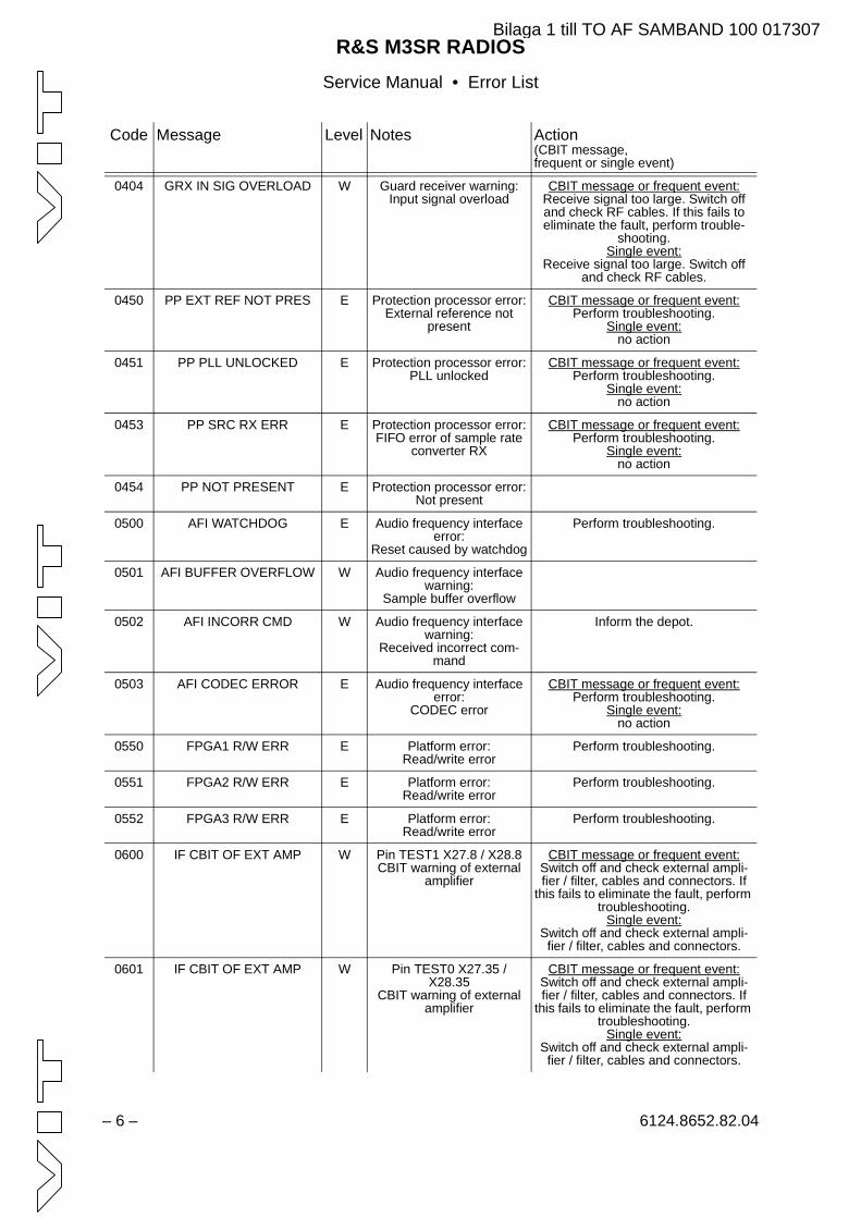
R&S M3SR RADIOSService Manual • Error List
– 6 – 6124.8652.82.04
0404 GRX IN SIG OVERLOAD W Guard receiver warning:Input signal overload
CBIT message or frequent event:Receive signal too large. Switch off and check RF cables. If this fails to eliminate the fault, perform trouble-
shooting.Single event:
Receive signal too large. Switch off and check RF cables.
0450 PP EXT REF NOT PRES E Protection processor error:External reference not
present
CBIT message or frequent event:Perform troubleshooting.
Single event:no action
0451 PP PLL UNLOCKED E Protection processor error:PLL unlocked
CBIT message or frequent event:Perform troubleshooting.
Single event:no action
0453 PP SRC RX ERR E Protection processor error:FIFO error of sample rate
converter RX
CBIT message or frequent event:Perform troubleshooting.
Single event:no action
0454 PP NOT PRESENT E Protection processor error:Not present
0500 AFI WATCHDOG E Audio frequency interface error:
Reset caused by watchdog
Perform troubleshooting.
0501 AFI BUFFER OVERFLOW W Audio frequency interface warning:
Sample buffer overflow
0502 AFI INCORR CMD W Audio frequency interface warning:
Received incorrect com-mand
Inform the depot.
0503 AFI CODEC ERROR E Audio frequency interface error:
CODEC error
CBIT message or frequent event:Perform troubleshooting.
Single event:no action
0550 FPGA1 R/W ERR E Platform error:Read/write error
Perform troubleshooting.
0551 FPGA2 R/W ERR E Platform error:Read/write error
Perform troubleshooting.
0552 FPGA3 R/W ERR E Platform error:Read/write error
Perform troubleshooting.
0600 IF CBIT OF EXT AMP W Pin TEST1 X27.8 / X28.8CBIT warning of external
amplifier
CBIT message or frequent event:Switch off and check external ampli-fier / filter, cables and connectors. If
this fails to eliminate the fault, perform troubleshooting.
Single event:Switch off and check external ampli-fier / filter, cables and connectors.
0601 IF CBIT OF EXT AMP W Pin TEST0 X27.35 / X28.35
CBIT warning of external amplifier
CBIT message or frequent event:Switch off and check external ampli-fier / filter, cables and connectors. If
this fails to eliminate the fault, perform troubleshooting.
Single event:Switch off and check external ampli-fier / filter, cables and connectors.
Code Message Level Notes Action(CBIT message,frequent or single event)
Bilaga 1 till TO AF SAMBAND 100 017307
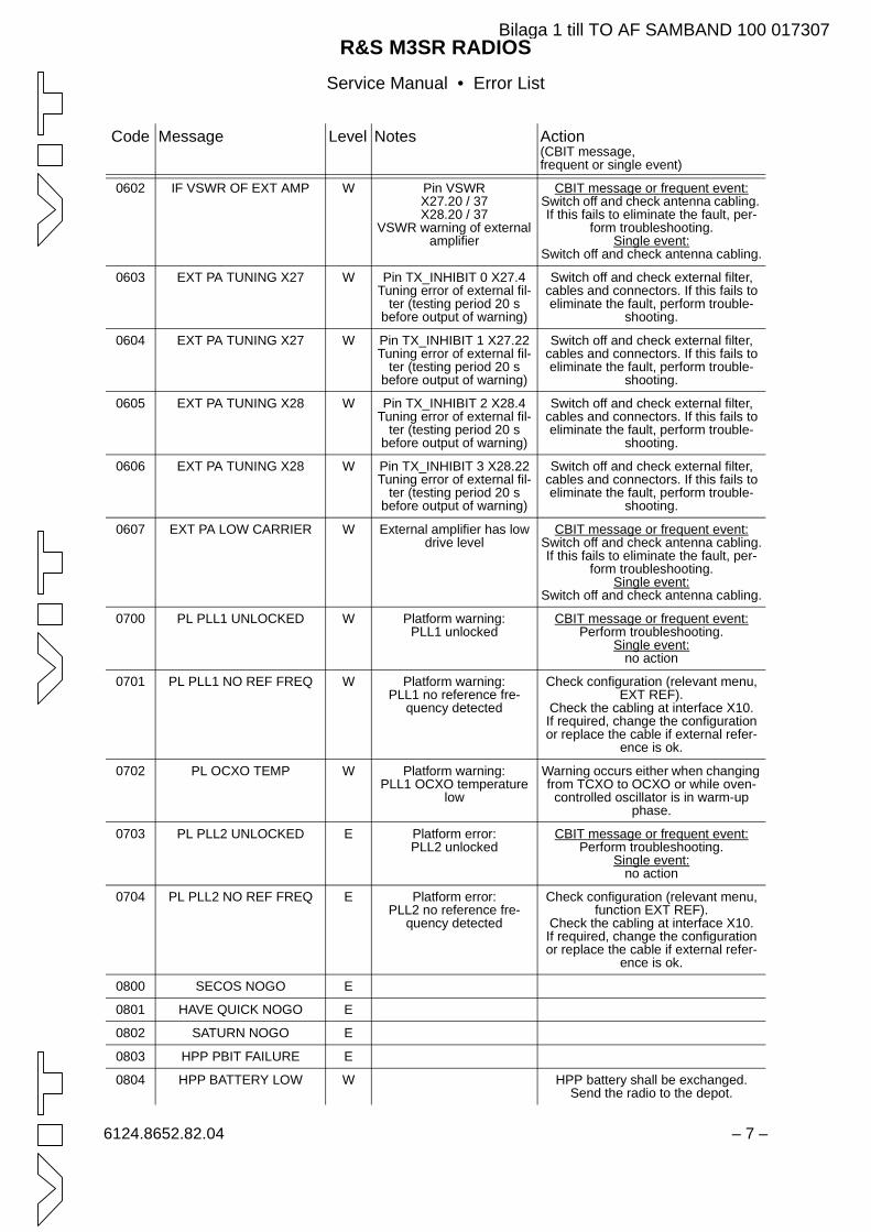
R&S M3SR RADIOSService Manual • Error List
6124.8652.82.04 – 7 –
0602 IF VSWR OF EXT AMP W Pin VSWR X27.20 / 37 X28.20 / 37
VSWR warning of external amplifier
CBIT message or frequent event:Switch off and check antenna cabling. If this fails to eliminate the fault, per-
form troubleshooting.Single event:
Switch off and check antenna cabling.
0603 EXT PA TUNING X27 W Pin TX_INHIBIT 0 X27.4Tuning error of external fil-
ter (testing period 20 s before output of warning)
Switch off and check external filter, cables and connectors. If this fails to eliminate the fault, perform trouble-
shooting.
0604 EXT PA TUNING X27 W Pin TX_INHIBIT 1 X27.22Tuning error of external fil-
ter (testing period 20 s before output of warning)
Switch off and check external filter, cables and connectors. If this fails to eliminate the fault, perform trouble-
shooting.
0605 EXT PA TUNING X28 W Pin TX_INHIBIT 2 X28.4Tuning error of external fil-
ter (testing period 20 s before output of warning)
Switch off and check external filter, cables and connectors. If this fails to eliminate the fault, perform trouble-
shooting.
0606 EXT PA TUNING X28 W Pin TX_INHIBIT 3 X28.22Tuning error of external fil-
ter (testing period 20 s before output of warning)
Switch off and check external filter, cables and connectors. If this fails to eliminate the fault, perform trouble-
shooting.
0607 EXT PA LOW CARRIER W External amplifier has low drive level
CBIT message or frequent event:Switch off and check antenna cabling.If this fails to eliminate the fault, per-
form troubleshooting.Single event:
Switch off and check antenna cabling.
0700 PL PLL1 UNLOCKED W Platform warning:PLL1 unlocked
CBIT message or frequent event:Perform troubleshooting.
Single event:no action
0701 PL PLL1 NO REF FREQ W Platform warning:PLL1 no reference fre-
quency detected
Check configuration (relevant menu, EXT REF).
Check the cabling at interface X10.If required, change the configuration or replace the cable if external refer-
ence is ok.
0702 PL OCXO TEMP W Platform warning:PLL1 OCXO temperature
low
Warning occurs either when changing from TCXO to OCXO or while oven-
controlled oscillator is in warm-up phase.
0703 PL PLL2 UNLOCKED E Platform error:PLL2 unlocked
CBIT message or frequent event:Perform troubleshooting.
Single event:no action
0704 PL PLL2 NO REF FREQ E Platform error:PLL2 no reference fre-
quency detected
Check configuration (relevant menu, function EXT REF).
Check the cabling at interface X10.If required, change the configuration or replace the cable if external refer-
ence is ok.
0800 SECOS NOGO E
0801 HAVE QUICK NOGO E
0802 SATURN NOGO E
0803 HPP PBIT FAILURE E
0804 HPP BATTERY LOW W HPP battery shall be exchanged. Send the radio to the depot.
Code Message Level Notes Action(CBIT message,frequent or single event)
Bilaga 1 till TO AF SAMBAND 100 017307
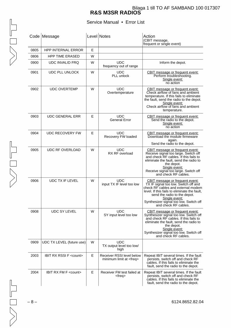
R&S M3SR RADIOSService Manual • Error List
– 8 – 6124.8652.82.04
0805 HPP INTERNAL ERROR E
0806 HPP TIME ERASED W
0900 UDC INVALID FRQ W UDCfrequency out of range
Inform the depot.
0901 UDC PLL UNLOCK W UDCPLL unlock
CBIT message or frequent event:Perform troubleshooting.
Single event:no action
0902 UDC OVERTEMP W UDCOvertemperature
CBIT message or frequent event:Check airflow of fans and ambient
temperature. If this fails to eliminatethe fault, send the radio to the depot.
Single event:Check airflow of fans and ambient
temperature.
0903 UDC GENERAL ERR E UDCGeneral Error
CBIT message or frequent event:Send the radio to the depot.
Single event:no action
0904 UDC RECOVERY FW E UDCRecovery FW loaded
CBIT message or frequent event:Download the module firmeware
again.Send the radio to the depot.
0905 UDC RF OVERLOAD W UDCRX RF overload
CBIT message or frequent event:Receive signal too large. Switch offand check RF cables. If this fails toeliminate the fault, send the radio to
the depot.Single event:
Receive signal too large. Switch offand check RF cables.
0906 UDC TX IF LEVEL W UDCinput TX IF level too low
CBIT message or frequent event:TX IF signal too low. Switch off and
check RF cables and external modemlevel. If this fails to eliminate the fault,
send the radio to the depot.Single event:
Synthesizer signal too low. Switch offand check RF cables.
0908 UDC SY LEVEL W UDCSY input level too low
CBIT message or frequent event:Synthesizer signal too low. Switch offand check RF cables. If this fails toeliminate the fault, send the radio to
the depot.Single event:
Synthesizer signal too low. Switch offand check RF cables.
0909 UDC TX LEVEL (future use) W UDCTX output level too low/
high
2003 IBIT RX RSSI F <count> E Receiver RSSI level below minimum limit at <freq>
Repeat IBIT several times. If the fault persists, switch off and check RF cables. If this fails to eliminate the fault, send the radio to the depot.
2004 IBIT RX FM F <count> E Receiver FM test failed at <freq>
Repeat IBIT several times. If the fault persists, switch off and check RF cables. If this fails to eliminate the fault, send the radio to the depot.
Code Message Level Notes Action(CBIT message,frequent or single event)
Bilaga 1 till TO AF SAMBAND 100 017307
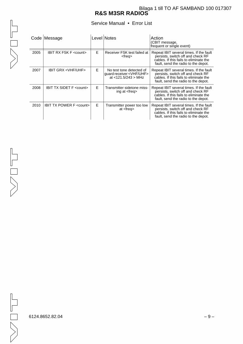
R&S M3SR RADIOSService Manual • Error List
6124.8652.82.04 – 9 –
2005 IBIT RX FSK F <count> E Receiver FSK test failed at <freq>
Repeat IBIT several times. If the fault persists, switch off and check RF cables. If this fails to eliminate the fault, send the radio to the depot.
2007 IBIT GRX <VHF/UHF> E No test tone detected of guard receiver <VHF/UHF>
at <121.5/243 > MHz
Repeat IBIT several times. If the fault persists, switch off and check RF cables. If this fails to eliminate the fault, send the radio to the depot.
2008 IBIT TX SIDET F <count> E Transmitter sidetone miss-ing at <freq>
Repeat IBIT several times. If the fault persists, switch off and check RF cables. If this fails to eliminate the fault, send the radio to the depot.
2010 IBIT TX POWER F <count> E Transmitter power too low at <freq>
Repeat IBIT several times. If the fault persists, switch off and check RF cables. If this fails to eliminate the fault, send the radio to the depot.
Code Message Level Notes Action(CBIT message,frequent or single event)
Bilaga 1 till TO AF SAMBAND 100 017307
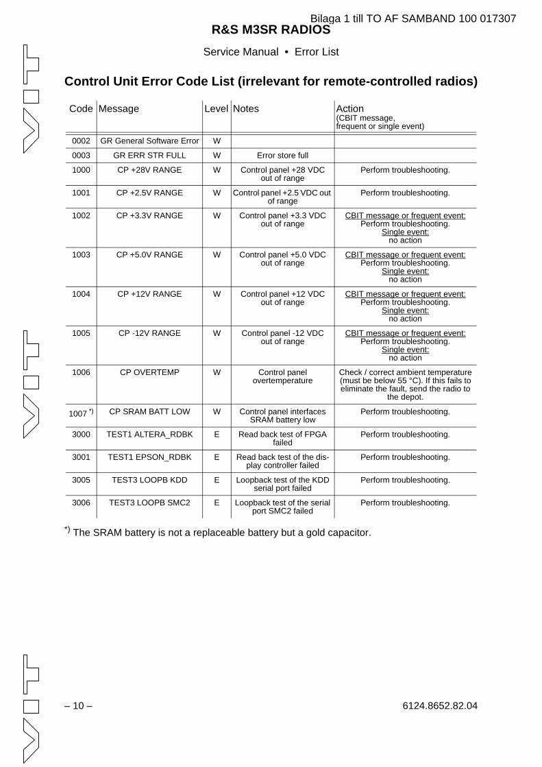
R&S M3SR RADIOSService Manual • Error List
– 10 – 6124.8652.82.04
Control Unit Error Code List (irrelevant for remote-controlled radios)
*) The SRAM battery is not a replaceable battery but a gold capacitor.
Code Message Level Notes Action(CBIT message,frequent or single event)
0002 GR General Software Error W
0003 GR ERR STR FULL W Error store full
1000 CP +28V RANGE W Control panel +28 VDCout of range
Perform troubleshooting.
1001 CP +2.5V RANGE W Control panel +2.5 VDC out of range
Perform troubleshooting.
1002 CP +3.3V RANGE W Control panel +3.3 VDCout of range
CBIT message or frequent event:Perform troubleshooting.
Single event:no action
1003 CP +5.0V RANGE W Control panel +5.0 VDCout of range
CBIT message or frequent event:Perform troubleshooting.
Single event:no action
1004 CP +12V RANGE W Control panel +12 VDCout of range
CBIT message or frequent event:Perform troubleshooting.
Single event:no action
1005 CP -12V RANGE W Control panel -12 VDCout of range
CBIT message or frequent event:Perform troubleshooting.
Single event:no action
1006 CP OVERTEMP W Control panelovertemperature
Check / correct ambient temperature (must be below 55 °C). If this fails to eliminate the fault, send the radio to
the depot.
1007 *) CP SRAM BATT LOW W Control panel interfaces SRAM battery low
Perform troubleshooting.
3000 TEST1 ALTERA_RDBK E Read back test of FPGA failed
Perform troubleshooting.
3001 TEST1 EPSON_RDBK E Read back test of the dis-play controller failed
Perform troubleshooting.
3005 TEST3 LOOPB KDD E Loopback test of the KDD serial port failed
Perform troubleshooting.
3006 TEST3 LOOPB SMC2 E Loopback test of the serial port SMC2 failed
Perform troubleshooting.
Bilaga 1 till TO AF SAMBAND 100 017307

Recommended Accessories
6125.1651.12.02 – R.1 / R.2 –
Power Supply
R&S IN 4000A
Antennas
R&S HK 014
not shown:R&S HK 012R&S HK 001
Control Units
R&S GB 4000C(remote version)
not shown:R&S GB 406.. on request
Filter and Amplifiers
R&S FD 430
not shown:R&S VU 210LR&S VU 220LR&S VD 480L
Handsets and Headsets
R&S GA 015
not shown:R&S GA 012R&S GA 013R&S GA 016H1
Mating Connectornot shown:R&S ZF 4410
Bilaga 1 till TO AF SAMBAND 100 017307

Bilaga 1 till TO AF SAMBAND 100 017307
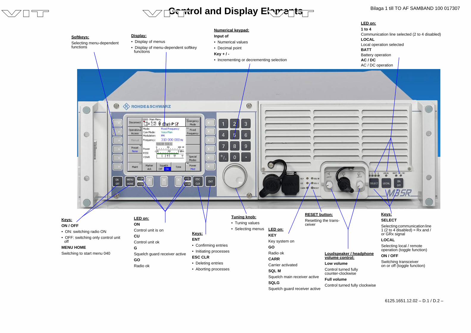
Control and Display Elements
6125.1651.12.02 – D.1 / D.2 –
LED on:1 to 4Communication line selected (2 to 4 disabled)LOCALLocal operation selectedBATTBattery operationAC / DCAC / DC operation
Tuning knob:• Tuning values• Selecting menus
Loudspeaker / headphonevolume control:Low volumeControl turned fullycounter-clockwiseFull volumeControl turned fully clockwise
Keys:ENT• Confirming entries• Initiating processesESC CLR• Deleting entries• Aborting processes
Keys:SELECTSelecting communication line1 (2 to 4 disabled) = Rx and /or GRx signalLOCALSelecting local / remoteoperation (toggle function)ON / OFFSwitching transceiveron or off (toggle function)
LED on:KEYKey system onGORadio okCARRCarrier activatedSQL MSquelch main receiver activeSQLGSquelch guard receiver active
LED on:ONControl unit is onCUControl unit okGSquelch guard receiver activeGORadio ok
Keys:ON / OFF• ON: switching radio ON• OFF: switching only control unit
offMENU HOMESwitching to start menu 040
RESET button:Resetting the trans-ceiver
Numerical keypad:Input of• Numerical values• Decimal pointKey + / -• Incrementing or decrementing selection
Display:• Display of menus• Display of menu-dependent softkey
functions
Softkeys:Selecting menu-dependentfunctions
Bilaga 1 till TO AF SAMBAND 100 017307

Bilaga 1 till TO AF SAMBAND 100 017307
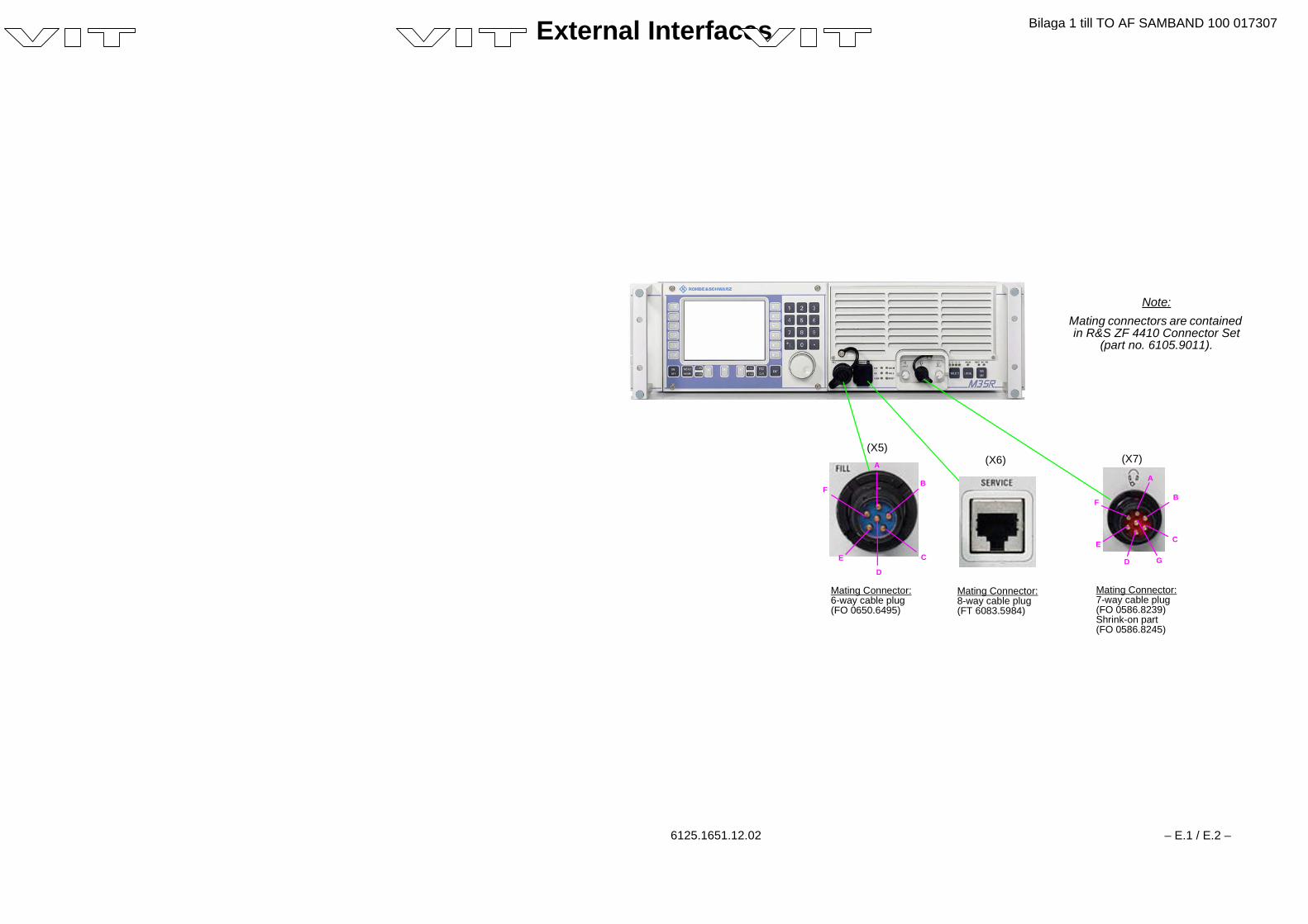
External Interfaces
6125.1651.12.02 – E.1 / E.2 –
Mating Connector:8-way cable plug(FT 6083.5984)
Mating Connector:7-way cable plug(FO 0586.8239)Shrink-on part(FO 0586.8245)
A
B
C
D
E
F
(X5)(X6) (X7)
B
C
GD
E
F
Note:Mating connectors are containedin R&S ZF 4410 Connector Set
(part no. 6105.9011).
Mating Connector:6-way cable plug(FO 0650.6495)
A
Bilaga 1 till TO AF SAMBAND 100 017307

Bilaga 1 till TO AF SAMBAND 100 017307
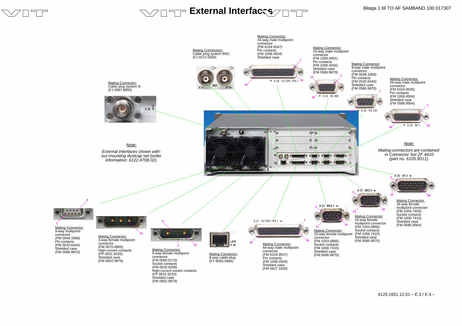
External Interfaces
6125.1651.12.01 – E.3 / E.4 –
Mating Connector:44-way male multipointconnector(FM 6104.9547)Pin contacts(FM 1006.4504)Shielded case(FM 0627.1826)
1
4416
Mating Connector:44-way male multipointconnector(FM 6104.9547)Pin contacts(FM 1006.4504)Shielded case
Mating Connector:15-way female multipointconnector(FM 1003.0866)Socket contacts(FM 1006.7410)Shielded case(FM 0586.9870)
Mating Connector:15-way femalemultipoint connector(FM 1003.0866)Socket contacts(FM 1006.7410)Shielded case(FM 0586.9870)
1
1011
1
1011
Mating Connector:26-way femalemultipoint connector(FM 1006.7403)Socket contacts(FM 1006.7410)Shielded case(FM 0586.9564)
1
10 26
Mating Connector:26-way male multipointconnector(FM 6104.9530)Pin contacts(FM 1006.4504)Shielded case(FM 0586.9564) 1
1026
Mating Connector:9-way male multipointconnector(FM 0048.3368)Pin contacts(FM 0520.6344)Shielded case(FM 0586.9870)
1
9
Mating Connector:15-way male multipointconnector(FM 1006.4491)Pin contacts(FM 1006.4504)Shielded case(FM 0586.9870)
1
15
10
1
44
Mating Connectors:Cable plug system BNC(FJ 0272.5930)
Mating Connector:5-way female multipointconnector(FM 0066.0173)Socket contacts(FM 0520.6338)High-current socket contacts(FP 0531.9233)Shielded case(FM 0652.9979)
A11
5
A1Mating Connector:3-way female multipointconnector(FM 0070.0800)High-current contacts(FP 0531.9233)Shielded case(FM 0652.9979)
Mating Connector:9-way multipointconnector(FM 0048.3368)Pin contacts(FM 0520.6344)Shielded case(FM 0586.9870)
9
1
Mating Connector:Cable plug system N(FJ 0087.8850)
Mating Connector:8-way cable plug(FT 6083.5984)
Note:Mating connectors are contained
in Connector Set ZF 4410(part no. 6105.9011).
Note:External interfaces shown with-out mounting dustcap set (order
information: 6122.4708.02).
16
Bilaga 1 till TO AF SAMBAND 100 017307

Bilaga 1 till TO AF SAMBAND 100 017307
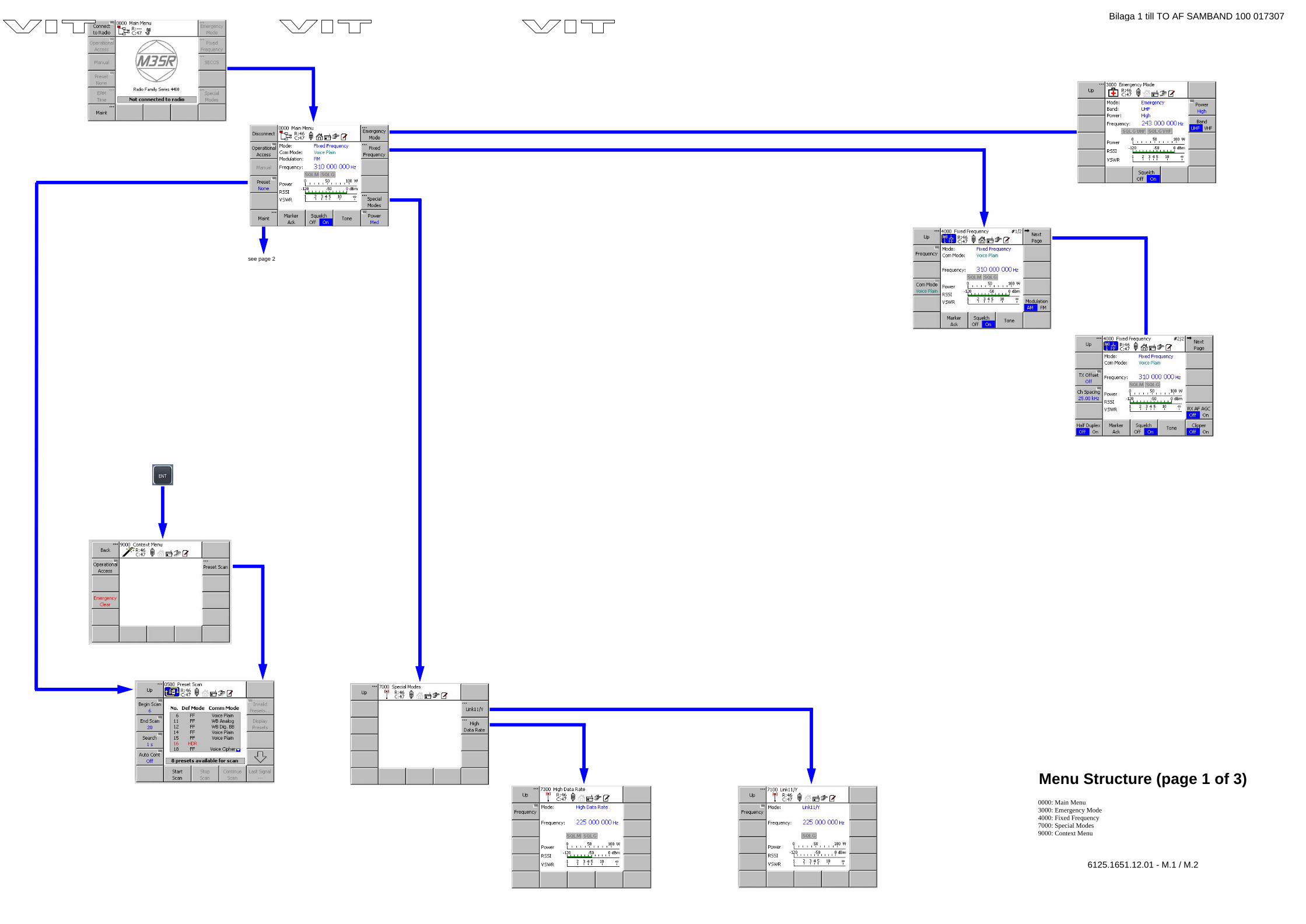
see page 2
Menu Structure (page 1 of 3)0000: Main Menu3000: Emergency Mode4000: Fixed Frequency7000: Special Modes9000: Context Menu
6125.1651.12.01 - M.1 / M.2
Bilaga 1 till TO AF SAMBAND 100 017307

Bilaga 1 till TO AF SAMBAND 100 017307
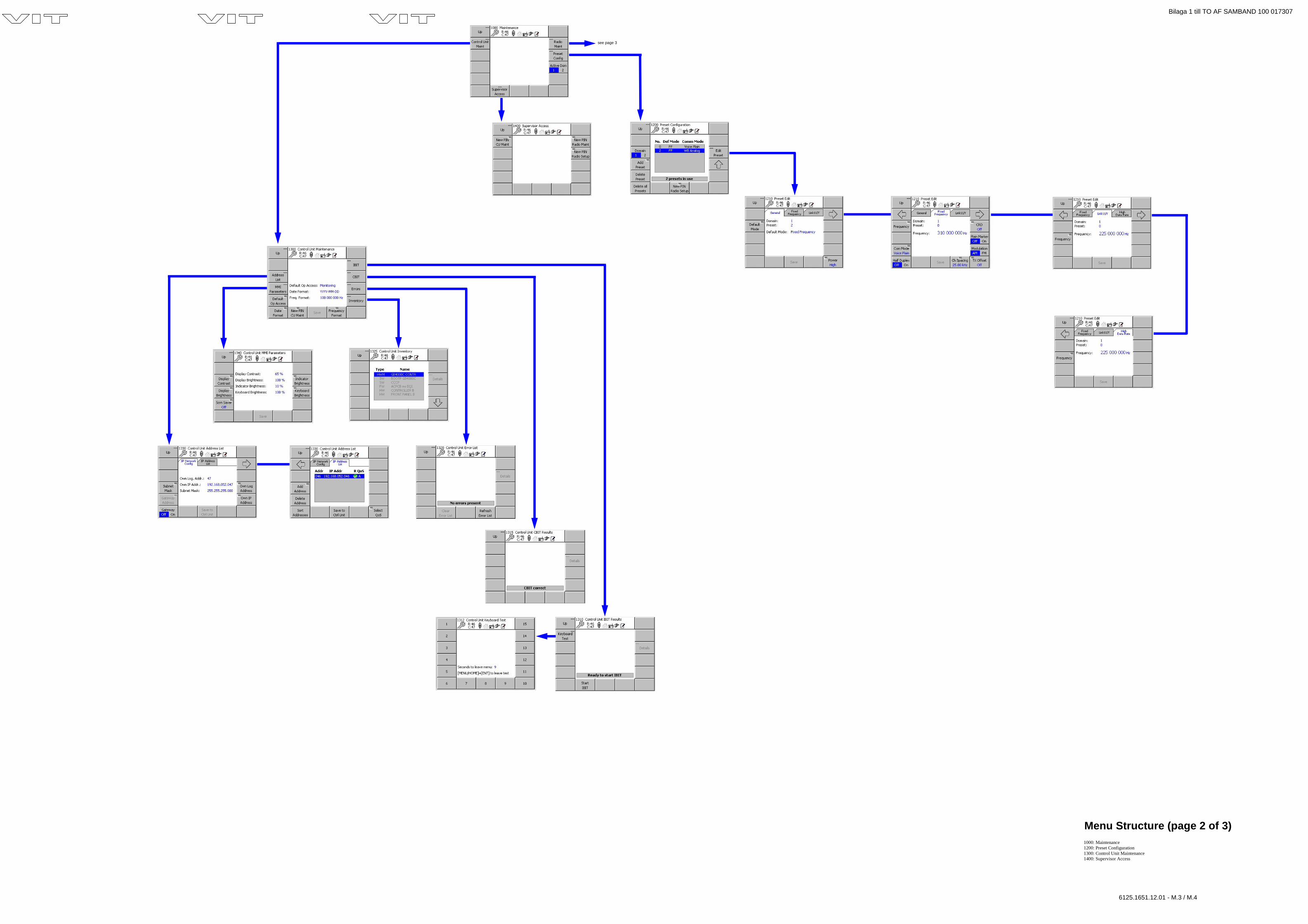
see page 3
Menu Structure (page 2 of 3)1000: Maintenance1200: Preset Configuration1300: Control Unit Maintenance1400: Supervisor Access
6125.1651.12.01 - M.3 / M.4
Bilaga 1 till TO AF SAMBAND 100 017307

Bilaga 1 till TO AF SAMBAND 100 017307
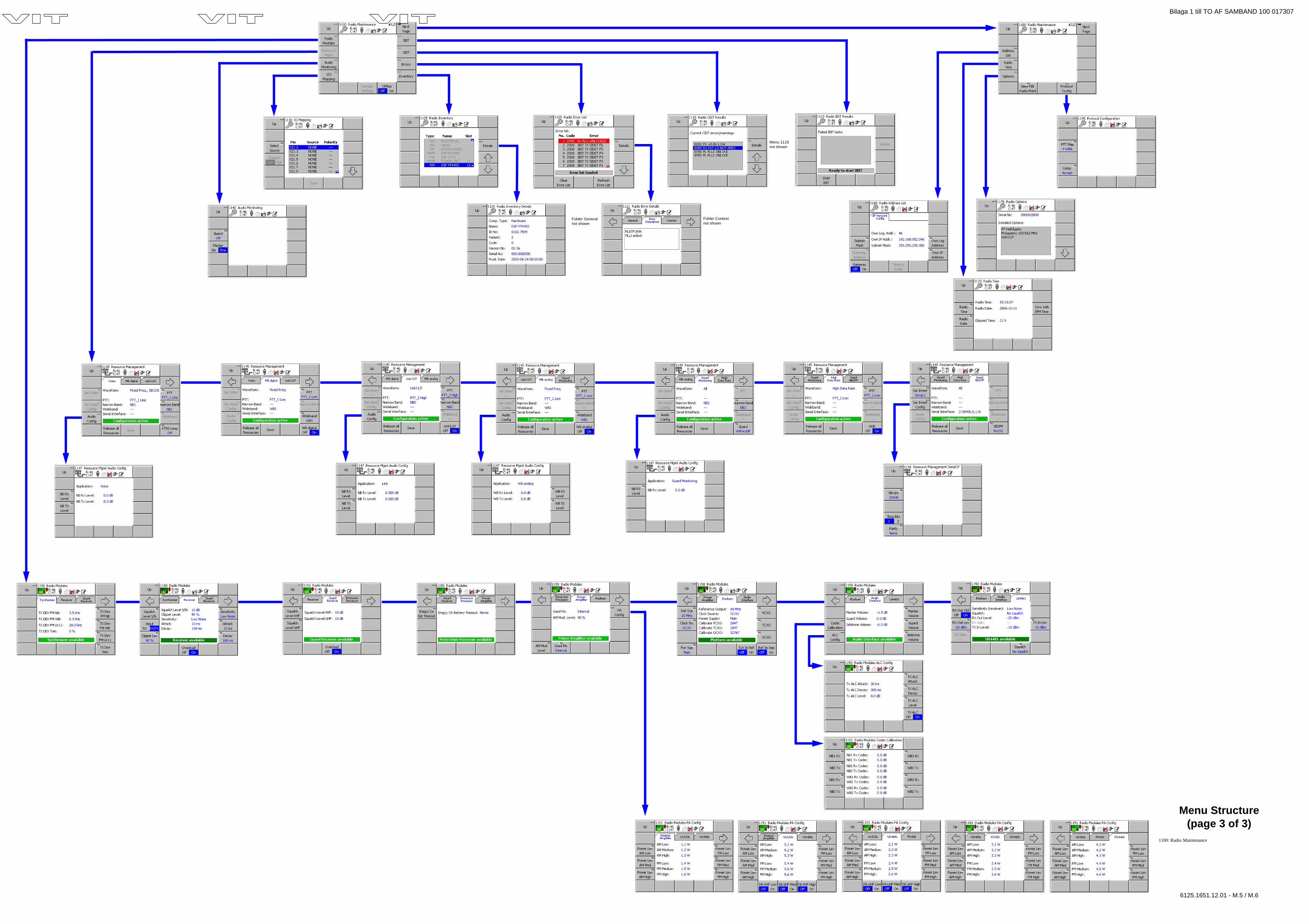
Folder Generalnot shown
Folder Contextnot shown
Menu 1116not shown
Menu Structure(page 3 of 3)
1100: Radio Maintenance
6125.1651.12.01 - M.5 / M.6
Bilaga 1 till TO AF SAMBAND 100 017307

Bilaga 1 till TO AF SAMBAND 100 017307