Embed Size (px)
DESCRIPTION
cxzcxzczxczxcz
Citation preview

Sustaining infrastructure is now a world priority. We need high performance infrastructure that can meet the demands of a
global population while preserving a vital and healthy environment for generations to come.
Bentley’s mission is to provide the software and services that support the enterprises and professionals who design, build, and operate the world’s infrastructure–sustaining the global economy and environment, for improved quality of life.
Find out more at www.bentley.com/STI
© 2011 Bentley Systems, Incorporated. Bentley and the “B” Bentley logo are either registered or unregistered trademarks or service marks of Bentley Systems, Incorporated or one of its direct or indirect wholly-owned subsidiaries. Other brands and product names are trademarks of their respective owners.
Bentley is Sustaining Infrastructure
Projects shown here include works by Bentley users Arup, Buro Happold, Foster + Partners, HDR, Laboratorio de Engenharia e Consultoria, Land Transport Authority, Populus, and T. Y. Lin.

5
Software for Road Infrastructure 3
CONTENTS
EditorMike Woof
Email: [email protected] Contributing Editor
Adrian GreemanSales Director
Manuel BattistaEmail: [email protected]
Tel: +44 1322 612069Sales ManagerYvonne Tindall
Email: [email protected]: +44 1622 844027Production Manager
Nick BondEmail: [email protected]
Tel: +44 1322 612065Marketing Director
Sarah O’BrienEmail: [email protected]
Tel: +44 1322 612080Offi ce Manager
Kelly ThompsonCirculation Manager
Preeti LalliDesigners
Simon Ward, Andy TaylderDavid Morley
Publisher/Managing DirectorAndrew Barriball
Email: [email protected]: +44 1322 612057
CEORoger Adshead
Email: [email protected]
Contact London Offi ce
Route One Publishing LtdHorizon House, Azalea Drive, Swanley, Kent, BR8 8JR, UK
Tel +44 1322 612055 Fax +44 161 603 0891
E-mail:[initialsurname]@ropl.com (eg:[email protected])
Nottingham Offi ceRoute One Publishing Ltd
Huntingdon House, 278-280 Huntingdon Street,
Nottingham NG1 3LY, United KingdomTel: +44 115 950 8098 Fax +44 161 603 0891
E-mail: [initialsurname]@ropl.com (eg: [email protected])
Reader Enquiry Service: [email protected]
Published by
© Route One Publishing Ltd 2011
No part of this publication may be reproduced in any form whatsoever without the express written
permission of the publisher. Contributors are encouraged to express their personal and
professional opinions in this publication, and accordingly views expressed herein are not
necessarily the views of Route One Publishing Ltd, or the International Road Federation.
From time to time statements and claims are made by the manufacturers and their
representatives in respect of their products and services. Whilst reasonable steps are taken
to check their accuracy at the time of going to press, the publisher cannot be
held liable for their validity and accuracy.
Printed by: Headley BrothersISSN 1463-6344
Informed Authority
4 INTRODUCTION Construction software offers users multiple benefi ts
5 ROAD ASSESSMENT & ENVIRONMENTAL PLANNING Mapping ice roads, sustainable planning
8 ROAD DESIGN Smart road design tools
10 GIS Using GIS for advanced survey techniques
12 ASSET MANAGEMENT Managing highways using GIS technology
17 BRIEFS New software innovations in brief
18 PLANNING Polish road corridor
19 INTEROPERABILITY Bentley’s moves towards data sharing
21 NEW SOFTWARE New software innovations from Autodesk and Bentley
26 CAD Suite of CAD tools
28 VISUALISATION/ SIMULATION 3D visualisation and simulation tools
34 BIM Explaining the BIM process
40 TRAFFIC CONTROL Using microsimulation for effective traffi c control
43 PROJECT REPORT Designing an interchange in Brisbane
45 LASER SCANNING/ POINT CLOUDS Using lasers to scan bridges
46 CLOUD COMPUTING Local authorities using the cloud
CoverIndra’s road assessment and planning program is being used for a road project in Argentina
34
8
26

the latest software taking full advantage of the increased data handling capabilities that result. Faster GPS systems combined with laser generated point cloud data and more comprehensive GIS information have had a huge effect. These have improved both the quality and quantity of information available, allowing engineers and designers a more comprehensive and accurate view of each project, even as work progresses on-site. The sheer quantity of data being generated has created its own issues, although the latest software tools are better able to cope with this more efficiently than before. By using the latest sophisticated scanning technologies, designers and engineers can source accurate data for use in design and visualisation processes. At the same time, some suppliers even allow their software tools to be rented, rather than bought, by users who may need certain
capabilities for a pre-determined period.
The Internet continues to play a vital role by allowing data to be transmitted and meaning that users can access information remotely. Even the software itself can be running on a far distant server and operated and used remotely through Internet-enabled technology. Visualisation tools have become more comprehensive, allowing engineers and the public to better understand a project prior to its construction. Feedback from the public or engineers can be received early on in a project, with the latest software automatically adding any changes made to the model. The digital model of a project can play a far more important role than before, being programmed into on-site equipment to guide machines, updated with recovered data and then becoming the document of record for the entire project. ■
The benefits to the user have multiplied and by employing the latest software, users can boost efficiency, speeding the design process, reducing the need for reworking, cutting project time and slashing overall costs. These latest innovations allow engineers to accurately simulate and evaluate complex projects in minute detail, prior to any physical construction activity taking place.
There is an industry trend towards better integration between software products from different providers. Interoperability is a key strategy between suppliers, in some cases even amongst direct rivals. Various firms have joined forces to ensure their products are compatible and even direct competitors have agreed common protocols. Data flow between software packages from different suppliers can be seamless, without the need for repackaging information to cope with a different format. This has been an important development as it boosts efficiency by reducing processing needs and reduces the risk of errors.
Meanwhile each passing week gives hardware suppliers time to provide greater processing power that is also cheaper, with
Software is a fast moving market
Fast moving technology and innovations has meant that construction software has come a long way since the 1980s when the first purpose-developed programs were devised
“Visualisation tools have become more comprehensive, allowing engineers and the public to better understand a project prior to its construction
”
INTRO
4 Software for Road Infrastructure

Software for Road Infrastructure 5
ROAD ASSESSMENT & ENVIRONMENTAL PLANNING
a large number of stakeholders have an interest in where the roads go. For the oil and mineral companies who want them for exploration a critical issue is choosing the shortest possible route. For the communities there are objections to the roads passing particular areas, or they may want them to come closer.
“Some 23 different criteria have to be satisfied from federal and state authorities to local towns and communities,” said consultant Atkins senior project manager Stephen Bourne. The international multidisciplinary firm has been part of a three year study to find a way to build, plan and route the roads.
“Then there are issues like polar bear habitat which you need to avoid for environmental and for obvious human safety reasons,” said Bourne. “Other natural flora and fauna has to be assessed too. On top there are practical engineering issues too,
such as the amount of water in the lakes along the route,” he added.
Unlike the Canadian roads, those in Alaska are in less hilly territory and usually do not need to pass across the lake surfaces. But the raw material for the roads is pumped from the watercourses and lakes and so just how much water is used is a critical issue. “Roads are formed with about a metre or more thickness of ice built up by spraying repeated layers,” he said. “In some places ‘ice bridges’ must be formed too, across stream valleys and other declivities so there is a lot of water needed.”
The road construction usually takes about two months and has to wait for the ground to freeze sufficiently. A hardness test using a simple penetrometer is done, measuring how far a rod will go into the ground after 25 measured blows. Seasonal water
In recent years one of the odder reality type TV programmes has been the series Ice Road Truckers. This gritty documentary series follows the fortunes and tribulations of long distance drivers taking heavy equipment loads hundreds of kilometres to remote mining and oil drilling camps in the sub-zero conditions of the Canadian north.
The huge trucks travel in winter on temporary roads formed by freezing water to make a load bearing track through snow, forest and, hair-raisingly, across lakes frozen solid in Arctic conditions. The trails melt quickly in the spring thaw, which is dangerous, and they have to be reformed again each winter by spraying water once the temperatures drop sufficiently.
A question the programmes rarely consider is how these roads are planned, engineered and routed. In fact the process is tightly controlled and not least the routes taken by the roads which can be highly sensitive for various engineering and environmental reasons.
In the adjacent US state of Alaska the same issues prevail and
GIS maps for ice roadsA web based mapping system is helping mineral companies plan the winter “ice roads” used in the freezing Alaskan wilderness
Careful analysis is made of the various parameters to ensure that the road can be constructed on time and to the necessary specifications
▲

changes and possible climate change variations also have to be borne in mind and so both meteorological and climate data has to be considered too. Planning the best route is a complex business therefore and to aid all the different stakeholders a web based map and calculation system is being developed.
The consultant, together with the local university of Fairbanks’ environmental and water resources centre, directed by Professor William Schnabel, and researchers from further away at the University of Texas led by Professor Kelly Rumbelow, have been putting together a route planning program. It used route calculation algorithms being developed at Texas and other data. “It is built up on an ESRI GIS mapping software,” said Bourne “…and information from a lot of disparate databases has to be brought together to feed into that.” An ARC-GIS server is used for the mapping process and display.
“But we use Microsoft Silverlight for the service layer that integrates and calculates everything. That is an advantage because Silverlight uses Visual Basic as its code which is well known and does not involve learning another language.”
One of the functions of the central program is to plot the shortest route, which it does using an “anthill” algorithm he explained, “…which means a process similar to the way dispersed ants will settle on a short route to a piece of food once it is discovered.” The algorithm tries hundreds of routes, looking at the impact of dozens of factors, and settles on a top listing; 10 of these are offered up as choices on the Internet for various stakeholders to comment.
All this has taken some three years of development and the system has successfully been trialled internally. “But federal grants for the research have been hit by the economic troubles and there is still a bit more to do for it to go public,” said Bourne.
Once in place the mineral companies will be able to select a route and can get on with a design and as the freeze settles in. There may be scope to develop the system for other purposes too, perhaps using it for routeing light railways or service roads through awkward urban areas. ■
ESRIwww.esri.com
6 Software for Road Infrastructure
ROAD ASSESSMENT & ENVIRONMENTAL PLANNING
The lakes along the route provide additional challenges to the construction of the road
Heavy duty equipment is carried along the ice road
The road has to carry heavy trucks and is engineered to carry their weight
The tundra itself presents a challenging environment that is difficult to traverse except by air
The harsh Actic conditions are tough for humans but provide a habitat for wildlife, a factor the road designers have to accommodate
▲

Software for Road Infrastructure 7
ROAD ASSESSMENT & ENVIRONMENTAL PLANNING
“”
A “serious games” approach is being used for the project said Indra, which will have an “artificial intelligence” engine to calculate the effects of projects
Sustainability is the watchword for projects and developments in the 21st century and that applies to highways and roads as much as anything else. The benefits of schemes have to weighed against the impact they have in economic and environmental terms.
Early stage alignment planning for roads and highways with tools like Autodesk’s Infrastructure Modeller 2012 or Eagle Point’s earlier Landsketch for Highways, described last year, can give an idea of the road impact. But they do not calculate in detail its effect on a region in economic, social and ecological terms.
A new complex assessment system is being developed in Spain that should do just that. The Estrateco project aims to simulate the regional environment through which a project will pass and calculate just how it will impinge on various natural resources, communities and local activities. It can determine what overall cost a highway will have in reducing forest for example, but stimulating other developments.
The program, being developed by major IT house Indra in Spain, is part of a joint cooperative research project with Argentina under the Iberoeka umbrella. Joint work is being done by Indra’s Software Lab network and environmental services company Ambiental Argentina.
The project aims to create a simulation of a region with all its natural resources and assets represented. Aerial photography,
ground scans, ground photography, maps and text data will be combined to identify natural resources such as forests, water, wildlife, and minerals, and more importantly their values both economically and ecologically.
A “serious games” approach is being used for the project said Indra, which will have an “artificial intelligence” engine to calculate the effects of projects. It takes into account a global vision of an area, said Indra manager of accessible technologies Alicia Fernández del Viso.
“Existing environmental management systems help companies assess the impact they make on an area, and can help identify significant factors for enhancing control of raw materials, optimising waste and emission costs, reducing accidents, and diminishing the deleterious effects of a project on the environment,” he said. The information can help maximise the chances of planning approval and perhaps approvals for subsidies or loans.
“But they work at single project level whereas our system will give a global view of all the companies, factories, parklands, natural resources and transport in the area,” he said. The complex interactions between these elements and the way they are affected by new projects are assessed.
“That includes a causal model that shows the connections between all these things and
how changes in one feedback and change again the values for others.” The calculated system is displayed visually and can be operated in the same kind of way as modern video games to allow ease of use.
In the software “natural assets are managed through a simulator connected to the Estrateco ‘knowledge system’,” he explained further. There is also a social network in the project to facilitate interactions and to both inform and receive information from the local community.
Dashboards display factors such as pollution, noise levels, erosion impacts, water levels, micro-climate and biodiversity, and the level of industrialisation, parkland, residences and infrastructure is all displayed.
The system works along principles established in the “Economics of ecosystems and biodiversity” TEEB report said Fernández. The report set principles for calculating ecosystem values in the overall GDP output of countries.
The project has so far completed the analysis and definition of requirements and is well into the development of the interface and the logical core processes. Pilots are underway in Argentina in the Tucuman area at Las Yungas and Valles Calchiquíes. The software should be ready next spring. ■
Indrawww.indracompany.com
Sustainable planningA complex new program aims to assess accurately the economic and environmental impact of new projects
alternatively has the basic capacities but is then orientated towards pipe network design. “And there is a comprehensive package which incorporates all of these,” said Bar.
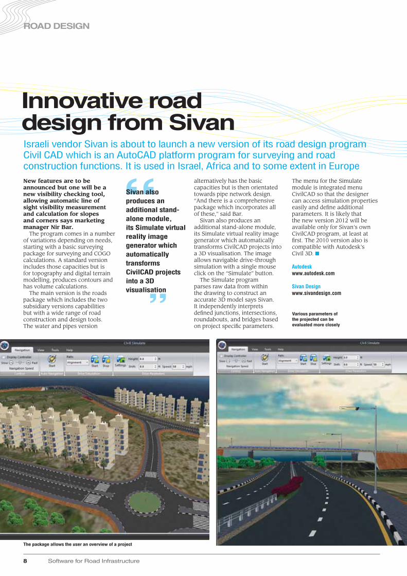
Sivan also produces an additional stand-alone module, its Simulate virtual reality image generator which automatically transforms CivilCAD projects into a 3D visualisation. The image allows navigable drive-through simulation with a single mouse click on the “Simulate” button.
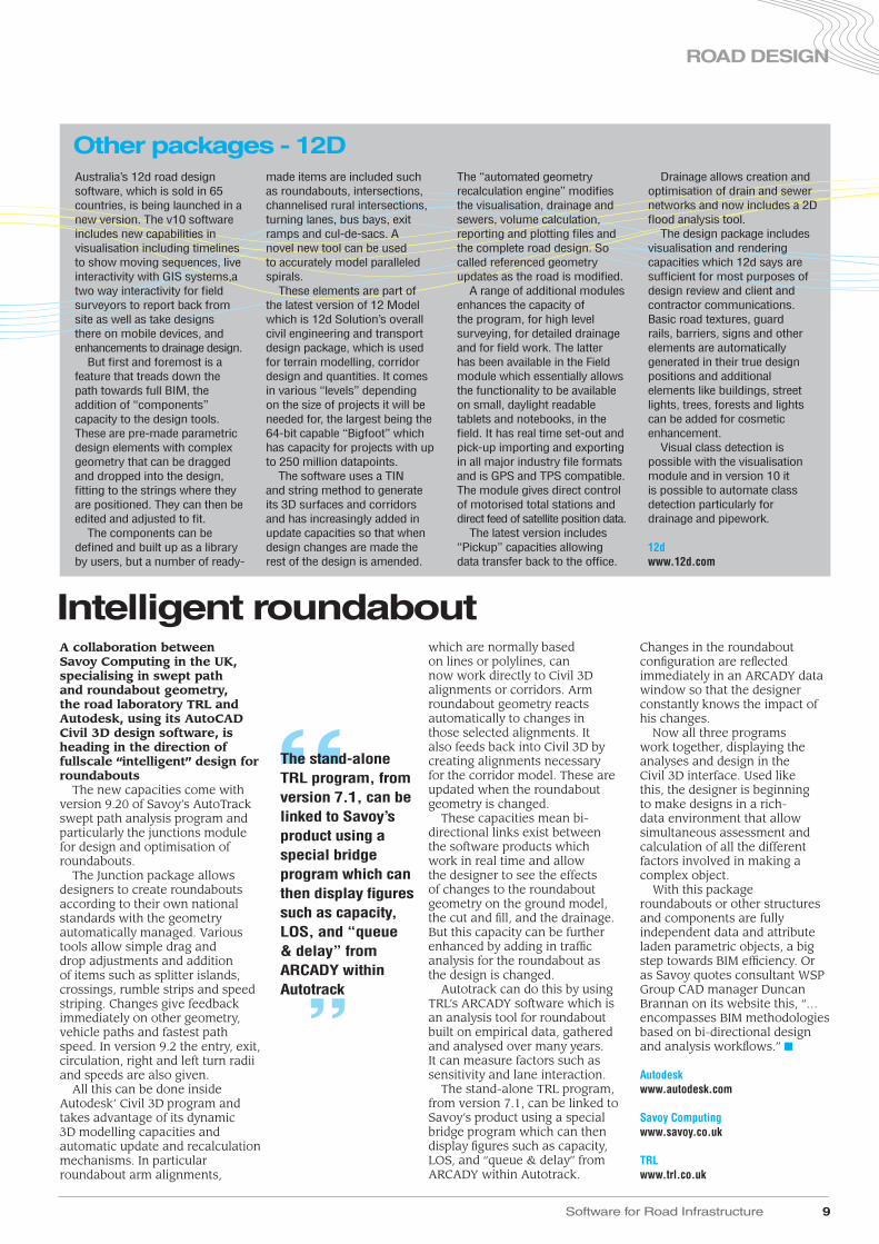
The Simulate program parses raw data from within the drawing to construct an accurate 3D model says Sivan. It independently interprets defined junctions, intersections, roundabouts, and bridges based on project specific parameters.
The menu for the Simulate module is integrated menu CivilCAD so that the designer can access simulation properties easily and define additional parameters. It is likely that the new version 2012 will be available only for Sivan’s own CivilCAD program, at least at first. The 2010 version also is compatible with Autodesk’s Civil 3D. ■
Autodeskwww.autodesk.com
Sivan Designwww.sivandesign.com
New features are to be announced but one will be a new visibility checking tool, allowing automatic line of sight visibility measurement and calculation for slopes and corners says marketing manager Nir Bar.
The program comes in a number of variations depending on needs, starting with a basic surveying package for surveying and COGO calculations. A standard version includes those capacities but is for topography and digital terrain modelling, produces contours and has volume calculations.
The main version is the roads package which includes the two subsidiary versions capabilities but with a wide range of road construction and design tools. The water and pipes version
Innovative road design from SivanIsraeli vendor Sivan is about to launch a new version of its road design program Civil CAD which is an AutoCAD platform program for surveying and road construction functions. It is used in Israel, Africa and to some extent in Europe
8 Software for Road Infrastructure
ROAD DESIGN
“Sivan also produces an additional stand-alone module, its Simulate virtual reality image generator which automatically transforms CivilCAD projects into a 3D visualisation
”
The package allows the user an overview of a project
Various parameters of the projected can be evaluated more closely
Software for Road Infrastructure 9
ROAD DESIGN
which are normally based on lines or polylines, can now work directly to Civil 3D alignments or corridors. Arm roundabout geometry reacts automatically to changes in those selected alignments. It also feeds back into Civil 3D by creating alignments necessary for the corridor model. These are updated when the roundabout geometry is changed.
These capacities mean bi-directional links exist between the software products which work in real time and allow the designer to see the effects of changes to the roundabout geometry on the ground model, the cut and fill, and the drainage. But this capacity can be further enhanced by adding in traffic analysis for the roundabout as the design is changed.
Autotrack can do this by using TRL’s ARCADY software which is an analysis tool for roundabout built on empirical data, gathered and analysed over many years. It can measure factors such as sensitivity and lane interaction.
The stand-alone TRL program, from version 7.1, can be linked to Savoy’s product using a special bridge program which can then display figures such as capacity, LOS, and “queue & delay” from ARCADY within Autotrack.
Changes in the roundabout configuration are reflected immediately in an ARCADY data window so that the designer constantly knows the impact of his changes.
Now all three programs work together, displaying the analyses and design in the Civil 3D interface. Used like this, the designer is beginning to make designs in a rich-data environment that allow simultaneous assessment and calculation of all the different factors involved in making a complex object.
With this package roundabouts or other structures and components are fully independent data and attribute laden parametric objects, a big step towards BIM efficiency. Or as Savoy quotes consultant WSP Group CAD manager Duncan Brannan on its website this, “…encompasses BIM methodologies based on bi-directional design and analysis workflows.” ■
Autodeskwww.autodesk.com
Savoy Computingwww.savoy.co.uk
TRLwww.trl.co.uk
A collaboration between Savoy Computing in the UK, specialising in swept path and roundabout geometry, the road laboratory TRL and Autodesk, using its AutoCAD Civil 3D design software, is heading in the direction of fullscale “intelligent” design for roundabouts
The new capacities come with version 9.20 of Savoy’s AutoTrack swept path analysis program and particularly the junctions module for design and optimisation of roundabouts.
The Junction package allows designers to create roundabouts according to their own national standards with the geometry automatically managed. Various tools allow simple drag and drop adjustments and addition of items such as splitter islands, crossings, rumble strips and speed striping. Changes give feedback immediately on other geometry, vehicle paths and fastest path speed. In version 9.2 the entry, exit, circulation, right and left turn radii and speeds are also given.
All this can be done inside Autodesk’ Civil 3D program and takes advantage of its dynamic 3D modelling capacities and automatic update and recalculation mechanisms. In particular roundabout arm alignments,
Intelligent roundabout
“The stand-alone TRL program, from version 7.1, can be linked to Savoy’s product using a special bridge program which can then display figures such as capacity, LOS, and “queue & delay” from ARCADY within Autotrack
”
Australia’s 12d road design software, which is sold in 65 countries, is being launched in a new version. The v10 software includes new capabilities in visualisation including timelines to show moving sequences, live interactivity with GIS systems,a two way interactivity for field surveyors to report back from site as well as take designs there on mobile devices, and enhancements to drainage design.
But first and foremost is a feature that treads down the path towards full BIM, the addition of “components” capacity to the design tools. These are pre-made parametric design elements with complex geometry that can be dragged and dropped into the design, fitting to the strings where they are positioned. They can then be edited and adjusted to fit.
The components can be defined and built up as a library by users, but a number of ready-
made items are included such as roundabouts, intersections, channelised rural intersections, turning lanes, bus bays, exit ramps and cul-de-sacs. A novel new tool can be used to accurately model paralleled spirals.
These elements are part of the latest version of 12 Model which is 12d Solution’s overall civil engineering and transport design package, which is used for terrain modelling, corridor design and quantities. It comes in various “levels” depending on the size of projects it will be needed for, the largest being the 64-bit capable “Bigfoot” which has capacity for projects with up to 250 million datapoints.
The software uses a TIN and string method to generate its 3D surfaces and corridors and has increasingly added in update capacities so that when design changes are made the rest of the design is amended.
The “automated geometry recalculation engine” modifies the visualisation, drainage and sewers, volume calculation, reporting and plotting files and the complete road design. So called referenced geometry updates as the road is modified.
A range of additional modules enhances the capacity of the program, for high level surveying, for detailed drainage and for field work. The latter has been available in the Field module which essentially allows the functionality to be available on small, daylight readable tablets and notebooks, in the field. It has real time set-out and pick-up importing and exporting in all major industry file formats and is GPS and TPS compatible. The module gives direct control of motorised total stations and direct feed of satellite position data.
The latest version includes “Pickup” capacities allowing data transfer back to the office.
Drainage allows creation and optimisation of drain and sewer networks and now includes a 2D flood analysis tool.
The design package includes visualisation and rendering capacities which 12d says are sufficient for most purposes of design review and client and contractor communications. Basic road textures, guard rails, barriers, signs and other elements are automatically generated in their true design positions and additional elements like buildings, street lights, trees, forests and lights can be added for cosmetic enhancement.
Visual class detection is possible with the visualisation module and in version 10 it is possible to automate class detection particularly for drainage and pipework.
12dwww.12d.com
Other packages - 12D

This package allows processing of integrated survey projects in Trimble Business Center and then moving survey, scan and image data to Trimble RealWorks to complete point-cloud and image processing. Media fi les, such as digital photos captured with the Trimble TSC3 controller and Trimble Tablet can be displayed, edited, and exported to GIS and Google Earth. The new Data Processing Service is available from the Trimble Business Center 2.50 software and Trimble Connected Community portal. The service means a user can send raw GNSS observation fi les to an Internet processing service, such as AUSPOS and Online Positioning User Service (OPUS), which returns a corrected co-ordinate for the observed control point. OPUS returns an XML fi le that can be imported to Trimble Business Center to incorporate processed points with other survey data. The Data Processing Service can also automatically convert Trimble-format fi les to RINEX, and read antenna information for verifi cation and editing.
Meanwhile Trimble’s updated RealWorks Software package is designed to broaden applications in 3D scanning duties, a signifi cant step for the construction design sector. The RealWorks version 7.0 incorporates the newly approved ASTM International E57 E2807 data exchange standard for 3D imaging systems. By providing full interoperability for 3D scanning data, this allows users more choices for design software, depending on their applications and workfl ow. Trimble RealWorks is a stand-alone solution for the interpretation and 3D rendering of scan point cloud data. “The ASTM Committee E57 E2807 standard is a major enhancement for 3D scanning customers across a variety of applications,” said David Fitzpatrick, general manager of Trimble’s Power, Process
and Plant Division. “It gives the users a standard way to utilise 3D scanning data in their offi ce software of choice. Support of the new standard demonstrates Trimble’s continued commitment to enhance the productivity of our customers by supporting their common workfl ows and represents the next step in Trimble’s long line of innovation for the 3D scanning industry.”
Trimble claims to have been the fi rst supplier to introduce standard surveying workfl ows in 3D scanning instruments and the fi rst to make a hybrid scanner/total station commercially available with the Trimble VX spatial station. ■
Trimblewww trimble com
The version 2.50 of the Business Center software allows survey managers to combine GNSS and optical surveying data as well as digital image information from surveying instruments into a single fi le.
This data can then be supplied to a range of applications such as GIS, photogrammetry and CAD. Using this package with Trimble Access Services allows clients to collaborate through the Trimble Connected Community portal throughout the phases of the project. The software advance allows effi cient integrated surveying, with its associated benefi ts of productivity, performance and convenience. Trimble Business Center integrates common survey offi ce processing tasks for GNSS and optical terrestrial surveying data into a single package. Trimble Access Services provides a suite of web-based applications that improve survey effi ciency by allowing sharing of information. This provides a fast information fl ow from the fi eld and allows last-minute changes from the offi ce. Trimble Business Center 2.50 includes new features that give offi ce staff the ability to use the integrated survey workfl ow. The program allows users to export or import reduced-point and observed-point information to and from other applications.
Smarter surveyingTrimble is now offering improved software for the surveying sector as well as a new data processing service and upgraded scanning capabilities
10 Software for Road Infrastructure
GIS
The sophisticated scanning solution from Trimble can be integrated with its software suite
A multi-layered GIS system is being used by the UK’s Luton Borough Council for its highways maintenance and asset management.
It uses more than 190 individual layers of mapped information ranging from addresses to parking zones, gritting routes, potholes and street lights.
Over 3,000 staff access the data held in the system using an Intranet or internal Internet system run by the council. Members of the public can also access the data via the council’s website where it can be used to report a range of defects and service delivery reports.
The system has been developed for the council by Croydon company GGP. According to the council GIS offi cer Peter Gell it currently has 192 individual layers of geographically referenced
GIS asset system

Software for Road Infrastructure 11
information. “We started using their
GIS system back in 1998 when the initial map layers were compiled from old hand drawn highways maps,” said Gell. “Over the years we have seen a rise in the number of requests from other departments to have their data added to the system and that is how we have arrived at this point with nearly seventy day to day users of the system and with access to the data from every desktop PC. The geographically referenced data is also used to power our online mapping system that provides members of the public with a ‘do it online’ option.”
“Visitors to the Council’s website can identify the location of an abandoned car, highway defect or
missed bin, for example, and when they click on the map it automatically tells them who is responsible for the issue and displays contact details,” he said.
Data in the system is stored in an international standard format defined by the Open Geospatial Consortium OGC. The capacity to read from and write to spatial databases directly means information can be effectively shared between departments and other organisations.
It is part of eliminating isolated data silos, reducing data duplicity and improving system interoperability. By joining diverse datasets there is a richer information resource overall. ■
GGPwww.ggpsystems.co.uk
FREE subscription to ITS Internationalwhen you register online @ www.roplreg.com
● 12 months supply of ITS International magazine (6 issues per year) in print
● The ITS International eNewsletter – emailed twice a month to over 36,000 qualified individuals
● Unlimited access to the ITS Internationalwebsite – with over 9 years of archived industry information in a fully searchable format
● Specials and supplements that focus on specific areas
A subscription to ITS International gives you:
Register for FREE online @ www.roplreg.com
Vol.1
7 Issu
e N
o.6
Nove
mber/D
ece
mber 2
011 w
ww
.itsinte
rnatio
nal.co
m

become familiar with new mobile technology and learn how to work with the cultural change which automatically follows when you introduce mobile working.”
“The new mobile solution enables our neighbourhood workers to go straight out to their daily inspections without coming anywhere near the office. As fully remote workers they can perform all their tasks in the field using their mobile devices, including handling emails, and go straight back home at the end of the day. We have also found that the solution improves the timeliness and quality of the information collected. Inspectors can log the coordinates of defects on a graphical map interface, take photographs, perform risk assessments, raise works orders, update customer service requests and complete a range of different types of inspections and condition surveys. All the data becomes available in the central system in near real time. It also integrates fully with Symology’s Street Works module, ensuring full compliance with the Traffic Management Act. Street works
notices are created automatically upon import, for the Council’s own works raised on the mobile. The way it works is very impressive,” said Carter and he continued, “You can tap in all the details, press the send button and, within a second, it appears in the back office core system. The ability is just amazing. If it’s cold, for example, the inspectors can just look up the MET office website and call out gritters for the following morning if necessary. It’s also important to emphasise that having more complete, timely data in the central system enables faster - and therefore cheaper - settlement of insurance liability claims where appropriate, and further ensures that the Traffic Manager is always completely up-to-date.”
Starting a project of this nature requires solid project management and Solihull established a project group that included representatives from all the stakeholders. The mobile software project was kicked off with a 6 month development phase that included monitoring four different mobile devices on
In 2008, Solihull Metropolitan Borough Council (Solihull) approved a project to introduce a software solution using handheld devices, making its network teams fully mobile. Today, Solihull is using mobile technology to improve service levels and change the way that inspectors carry out their roles while achieving multiple efficiency savings in the process. In August 2010, their innovative solution won the Communicator Telecoms Innovation Award established to recognise excellence in Public Sector Communications.
Potholes, smashed kerbs and raised flagstones are all everyday problems that need to be tackled, preferably very quickly. This was the background for a project introducing Personal Digital Assistant (PDA) technology in Solihull based on Symology’s Insight Mobile Solution. The solution has just been awarded the Communicator Telecoms Innovation Award with the following motivation from the judges
“.. An innovative mobile application that has the potential to deliver huge benefits both for council inspectors and for the environment of residents...”
Directorate performance manager, David Carter, who project managed the mobile software project explained, “We used to have a process which required the neighbourhood coordinators to rely on a manual paper based system. This meant they had to be office based for a proportion of their work time to initiate service requests and gather customer requests and this took away valuable time from the core functions they need to perform within the community. The main drivers behind the mobile solution were requirements to improve the overall efficiency, improve the NRSWA recording and to help implement changes in the Highways Act which required an increase in inspections. At the same time, we also wanted to
In our hands Novel mobile software solution for highways and street lighting inspections
12 Software for Road Infrastructure
ASSET MANAGEMENT
The hand-held device is helping speeding speed maintenance and repair operations in Solihull
Software for Road Infrastructure 13
ASSET MANAGEMENT
we worked with before the system became operational. The expectation levels are however roughly as follows: 10% increase in community engagement activity; 10% increase in NRSWA Inspections; 25% increase in Asset Management Capture; 20% decrease in the amount of office space needed; and 10% decrease in mileage. I would think that by the end of next year we should be able to measure the actual outcome.”
Today, the solution is deployed to 15 Highways inspectors who use the system every day. They are using Vodaphone v1520 (Asus P550) devices running Windows mobile 6.0, equipped with a 3.5” screen, 3G GPRS and GPS. The next group of users are12 Street Lighting engineers, who will begin using the system shortly and, because of the nature of their work, will use the more rugged Trimble Juno devices running Windows 6.1 Classic.
According to Carter, “2010 would appear to be the year of tablet devices – spearheaded by the Apple iPad. We have purchased a rugged PC and we’re in the process of testing its functionality. We’re also considering netbook type devices as well as reviewing Windows 7. We have one tablet device on test currently within a Highways Inspection environment and we have another device being used in our highway planning environment – with the aim to reduce the need to print large
plans for site visits. There are, however, some downsides to tablet PC’s in comparison to PDA’s. They’re more expensive, they have lower battery life, they are heavier and we also have to bear in mind that a PDA is easy to conceal and hence protect from potential theft whereas a tablet is more visible and ‘tempting’. The upside to introducing tablets is that they allow direct access to the core back office system; they facilitate a single infrastructure both in terms of Audio Visual appearance and security and therefore require less training. I am confident that the tablet technology will come down in price and that they will come with a mainstream operating system which will eventually replace the need for the PDA’s. Using tablets will no doubt further improve the inspectors’ experience of agile working especially because the functionality is similar to the core system where the PDA has its own sub-infrastructure. Our plans for the next five years include looking at the new Symology handheld software - which has been re-developed to enable operation on tablet PC’s, an enhanced mobile mapping system, and new “quick-click” recording facilities - and looking at a replacement device either new PDA’s or tablets.” ■
Symologywww.symology.co.uk
a test system. It took some time to integrate the mobile solution with the existing Street Works Module and Symology’s technicians helped Solihull with this process. One of the issues that needed to be focused on when using a mobile solution is the security aspect. Solihull found that the security software could not keep up with the windows mobile operating systems and had to upgrade.
Carter explained, “In order to succeed with a software project which so massively changes the way we work, you need to establish a critical path and make sure that you have the relevant milestones and check points to incorporate feedback from the users. Therefore, we made sure that we had regular input from the user group throughout the process, from specification and development through to implementation and testing. Likewise, the technology providers – Vodaphone for the mobile devices and Symology for the software - worked closely with us throughout the entire process. The support we have had has been tremendous and our account manager from Symology feels like part of the team. It really is a good example of a partnership that works - and that includes Vodaphone.”
The system went operational in January 2009 with the mapping functionality added in August. Training was provided jointly by Solihull and Symology, with a follow-up drop-in session two months later to address any problems experienced. A training video was produced and made available on officers’ office desk tops. The council now plans to put the video directly on the hand-held devices, so if an inspector in the field is unsure about something, the video is available.
Carter said, “We wanted to ensure that 100% of our highways inspections were completed on time despite an increase in the numbers of inspections required and by maintaining the current staff levels. We also wanted to reduce the amount of travel and reduce the amount of paper work. We have set some targets which roughly indicate the efficiency improvements we expect to gain – but thus far the solution has not been fully in operation long enough for us to measure the benchmarks against the baselines
“
”
In order to succeed with a software project which so massively changes the way we work, you need to establish a critical path and make sure that you have the relevant milestones and check points to incorporate feedback from the users
● Modular mobile solution, fully integrated with the core back office Symology Insight Suite
● Standardised for Microsoft Windows handheld devices and 3G or GPRS mobile networks
● Traffic Management Act compliance through full integration with Symology’s Street Works Module
● GPS, Camera and 3G communications all integrated in semi-rugged Trimble Juno SC device
● Greater number of inspections, with more complete, better quality data
● Operating efficiencies from better utilised inspectors, improved handling of insurance liability claims, plus expected saving in fuel, travel time and paper work
● Minimal investment and maximum functionality through modular approach
● Future proof solution with regular free software updates catering for changes in requirements
Solihull Mobile Solution @ a Glance

road network every year and the result is a comprehensive overview of the state of Dutch roads. During a single survey, the ARAN provides data on pavement quality including rutting, surface texture and ride quality. The ARAN also captures HD-resolution Right-of-way imagery every 2m and the sensor data is then analysed by Rijkswaterstaat to estimate the pavement maintenance need of the upcoming year.
Over a period of years, the data captured by the ARAN accumulated at Rijkswaterstaat’s offices, but was rarely being used after analysis for pavement management. In parallel, Rijkswaterstaat employees in
the country developed a need to view the environment along a highway without having to leave the office. Extensive image capturing programs were considered, but deemed too expensive, specifically because a lot of visual data was already collected with the ARAN system. Instead this needed to be disseminated to Rijkswaterstaat’s 9,000 employees, spread across dozens of regional offices. Carrying out this proved to be a challenge, since the imagery alone measured over 1.5 Terabyte of data/year. Quickly providing access to this data over the existing corporate intranet infrastructure proved to be challenging.
In The Netherlands, one of the most densely populated countries of Europe, an extensive highway network is available to the public. The Dutch highway network is of vital importance to the country’s economy, which relies for a large part on international logistics with the Rotterdam sea port and Amsterdam airport as major hubs.
The Dutch highways are generally well maintained and of high quality, but this comes at a cost. To simplify road maintenance and save costs by using existing data sources, specialist firm Fugro was contracted by the executive body of the Dutch Ministry of Infrastructure and the Environment, the Rijkswaterstaat, to develop the Dutch Visual Road Database.
The Dutch highway system is maintained by Rijkswaterstaat, which ensures the safe and smooth flow of traffic on roads and waterways, protects against flooding, provides sufficient, clean water and supplies reliable and useful information. In total, its responsibility stretches a length of 3,042km of highways, mostly dual carriageways with two or more lanes/direction. In addition, Rijkswaterstaat is responsible for maintaining the national waterway network, including canals and rivers.
Dutch roads handle heavy traffic volumes on a daily basis and every kilometre of traffic jam is considered to bring significant economic damage. As a result it is crucial that the roads are of high quality and that their maintenance is performed without impeding traffic flow. To do so, Rijkswaterstaat has been a long time user of Fugro’s ARAN technology. This vehicle, the Automatic Road ANalyzer, provides full details of pavement quality while driving at regular traffic speeds.
The Rijkswaterstaat is using the ARAN vehicle to survey the entire
Going DutchThe Dutch Visual Road Database: a simple idea proves effective - Martin Kodde, Pim Voogd
14 Software for Road Infrastructure
ASSET MANAGEMENT
Using Fugro’s servers to host road data gathered by the ARAN vehicle from the Dutch road network has allowed a vast increase in network maintenance and management efficiency for Rijkswaterstaat
“ ”The Rijkswaterstaat is using the ARAN vehicle to survey the entire road network every year and the result is a comprehensive overview of the state of Dutch roads

Software for Road Infrastructure 15
ASSET MANAGEMENT
of operations, the number of users increased substantially. Some reported uses of the Visual Road Database included the investigation of a traffic sign plan at a dense highway junction. Before, Rijkswaterstaat employees would have to go out and check the current situation but they could now review the situations of the last two years from their office desk.
Another reported application of the Visual Road Database is the investigation of traffic barrier types and condition. This helps the local road maintainer to assess the replacement needs. Rijkswaterstaat expects that using the Visual Road Database will reduce costs and increase traffic safety since these investigations can for a large part be done from the office instead of
going out and drive slowly along the trajectory.
The Visual Road Database will be hosted by Fugro for the coming two years. Then, the use and features of this application will be assessed by Rijkswaterstaat and Fugro. So far, the Visual Road Database proved to be a viable tool for daily road maintenance, reducing maintenance costs and increasing safety. Since Fugro provides both the hosting as well as the application, Rijkswaterstaat is relieved over the next two years from the task of hosting a large amount of data and providing support to this service. ■
Fugrowww.fugro.co.uk
Besides the hosting itself, an ICT problem, tight integration of the data with the existing intranet WebGIS infrastructure was needed. This would allow easy entrance to the data for all employees and a familiar interface to the users. Since Rijkswaterstaat aims the re-use of data for reasons of cost efficiency, Rijkswaterstaat ordered Fugro to make the imagery available in a centralised fashion.
The solution was to implement an existing application for distributing ARAN data over the Internet. Fugro’s VisiWeb product is a fully web based application to access the imagery captured by ARAN and featured exactly the needs of Rijkswaterstaat. The application allows users to quickly drive through the data at high speed to quickly find spots of interest. The application also provides access to the full resolution of the image and all the administrative data that is attached to the imaged road segments. A simple map view displays the location of these road segments. Users can find a road segment by selecting properties from a database search window, or by clicking on a point in Rijkswaterstaat’s Map viewer application.
Since VisiWeb is an out-of-the-box application, the amount of development work was limited. Fugro converted all of Rijkswaterstaat’s last two years of data to a new, more efficient, database format. The VisiWeb application was fully adapted to match the corporate identity of Rijkswaterstaat and efficiently integrate into the existing intranet web map application. All of the 3TB of data is hosted on Fugro’s servers, shielded by firewalls that make sure only authorised employees have access to the data set.
Users of the Visual Road Database do not notice that they are accessing an externally hosted program, as the system is available through a single button in their Map viewer application. After clicking the button, the user clicks on a location in the map and is then brought directly to Fugro’s server where Visiweb will show up the corresponding image.
Soon after the introduction of the hosted ARAN imagery in the Visual Road Database, users started exploring the use of imagery in daily practice. Within two months
A GIS based road asset management system is being launched by the specialist highway survey company Yotta in the UK. It will be one of the first purely built on a GIS location foundation rather than starting with traditional linear reference systems.
Traditional systems store road data in a large database and then analyse that before displaying the results. GIS map modules are added to the systems for visual display as well as text and report display. But the new Yotta system stores all its data and analyse it via maps and map layers.
Called “Horizons” the new system is also one of the first “cloud based” asset management systems. That means it is being offered as a web based system, hosted and managed by Yotta itself, and accessed by users through an ordinary browser, such as Internet Explorer or Firefox.
“As a result firstly it is very simple to use,” said Simon Topp, Yotta sales and services manager. “Most asset management systems are quite complex and very intensive to learn and use with a variety of complex dashboards and
interactions to get used to.”He said a lot of systems were
used only by a few trained staff, “And if they leave sometimes no one knows what to do with it. We wanted to provide an interface that was easy to use and accessible so that the software can be used by anyone fairly quickly.”
The Horizons system is therefore very visual he said, starting from maps and building up layers of disparate information which can be matched and compared for analysis. “As long as you are familiar with browsers and Google Maps it is quite simple.”
Manish Jethwa, Yotta’s chief technology officer explained that Yotta has come to the development of asset management from a different direction because it is a survey company, providing asset inventories and road condition surveys from GPS synchronised video and laser scan vehicles, and sometimes traditional detailed walked surveys.
The aim initially was to allow clients to make much more use of the data that they have collected for them he said. But using GIS and geo-referenced
Effective asset management
▲

16 Software for Road Infrastructure
visual mapping allows all sorts of analysis such as plotting accident data against road geometry and surface condition. “But of course that is not limited to highways data; all kinds of asset data can be included.”
Survey data, asset data and other third party data can be easily combined he says and they then all become accessible from a browser so that engineers and managers can log on wherever they are to do analysis and make decisions about maintenance and replacement. For the moment he says the focus is on road and condition management. Yotta has its own pavement management system which can be used with Horizons.
At present the Yotta system will not displace the much greater functionality of other asset management systems said Jethwa, particularly in areas like job management and works control but it is not ruled out for the future. Street lighting, or structures management may well be possible as the software develops he says “and it has been moving quite fast in development.”
But the aim is to give authorities an easy and fl exible system with a strong emphasis on visualisation for working and examining the data. Jethwa said, “…which is where Horizons begins rather than it being an interface option on top of a big even clunky database. Remember we
originate with the Oxford Metric Group and a strong background in image analysis.”
Part of the philosophy of the system has been to focus on achieving a very clear interface he said. But the hosted system has advantages too for local authorities particularly in times of economic stringency. “Costs for a big database system are very much upfront, whereas this will be used on a licensed basis. Agencies do not have to install any software so it can be got up and running very quickly.”
Costs will vary depending on the size of an organisation but could be between £15,000 for a small network owner to £100,000 for larger agencies. The new Horizons system has been undergoing trials with a number of bodies during the last year and a fi rst operational system is likely to be installed this autumn. Topp says the response has been good and the interface impresses those who see it.
For the moment the Horizons asset management system is for the UK but there is no reason to stop it being tailored to local reference systems says Jethwa. He added that the UK government’s pavement management requirements have set a high standard in world terms which open up various possibilities for future development. ■
Yottawww.yotta.co.uk
“At present the Yotta system will not displace the much greater functionality of other asset management systems said Jethwa, particularly in areas like job management and works control but it is not ruled out for the futureUsing effective maintenance
strategies allows road surface issues to be tackled quickly, before they develop into greater problems ”
ASSET MANAGEMENT
▲

Software for Road Infrastructure 17
BRIEFS
A new entry to the road sign software market is Sign Design Pro from the UK firm Design Pro Software. As it says on the can, the program aims to automate and simplify the complex business of signage which is always surrounded by numerous rules, standards and requirements for specific typefaces, colours and visibility.
According to developer Martin Quigley the program has originated from specialist CAD technicians who have worked in the sector and know the specific problems
faced. It allows them to drastically reduce time taken on signage, from as much a day for each, checking and altering to a short period where the constraints and standards are automatically applied.
For the moment the program uses the latest AutoCAD platform, though Quigley hopes a Microstation version can appear soon. It is also suitable for British standards but a wider range of international standards are to be developed. ■
Design Pro Softwarewww.designprooftware.co.uk
Design innovation
TRL has launched a software product to help keep the UK’s roads moving when an incident or planned event threatens to create significant congestion. TEST, the Tool for Evaluating Strategies for Traffic, has been developed for operators of Traffic Control Centres to predict the consequences of actions they undertake on their network, in response to an incident.
Incidents, events and road works all have the potential to impact traffic patterns and flows and can often cause significant congestion and delay to the public. New regulations mean that local highway authorities (LHAs) are required to expand their existing planning beyond managing traffic on their own road network, to assessing the potential impact of any traffic management plans on neighbouring networks as well.
TEST uses traffic PTV’s VISSIM micro-simulation package integrated with
real time signal control mechanisms such as Split Cycle and Offset Optimisation Technique (SCOOT) and Microprocessor Optimised Vehicle Actuation (MOVA) to evaluate signal strategies. This enables operators to plan for events by presenting the software with different scenarios. A user can evaluate what would happen should a vehicle break down in a stretch of one-way road and how changing signals to allow more green time would affect tailbacks for example. The software allows different signal settings to be trialled and comparison of the results of different strategies to be viewed. This allows operators to decide upon effective strategies for events and implement them should they occur.
Operational efficiencies can be gained by testing offline multiple options for routes, lane closures and traffic signal plans prior to a planned event; or through the testing of new signalised junctions prior to their installation. This ensures
optimum operation of the junction at the implementation phase, reducing bedding in times and allowing road users to benefit.
Integrating TEST into the operator environment can also bring significant improvements to road user perception and satisfaction, by providing a smoother and more consistent experience to drivers through applying the most appropriate traffic signals and plans for a given scenario. TEST also delivers economic benefits by reducing congestion and delay by maximising the capacity of the existing road space, while maintaining shorter and more reliable journey times. The package has been designed based on open architecture standards, is user friendly, with users needing no previous micro-simulation experience to work with the tool. ■
PTVwww.ptv.de
TRLwww.trl.co.uk
Faster sign design can be achieved using a new package from Design Pro Software
Improving traffic flow
New technology from TRL could help keep the UK’s traffic moving more effectively and efficiently
18 Software for Road Infrastructure
PLANNING
A major road study by consultant Scott Wilson’s Polish office has led to changes in the planned alignment of a major highway over 300km long that will help protect and preserve significant wildlife zones and pristine forest.
The road in question is a much needed link between the Polish capital Warsaw and the three Baltic states of Latvia, Lithuania and Estonia lying to the north east. Trade has been growing with these countries and substantially since they and Poland acceded to the European Union a few years ago.
“The existing two way road to Budziska in Lithuania is carrying a high load of freight traffic
and passengers,” said senior transportation analyst Wacław Jastrz bski, “…and is the only land connection to those three countries.”
Even more significantly it is their only route out into the European market. Since the EU principle is one of interconnectedness it is also a key part of the trans-European Network (TEN) developments.
Plans for a dual two lane expressway connection were considered in the 1990s but have attracted significant political and “green” hostility because of important plant and animal species such as rare swans and forest animals. These objections gained further weight by the designation of Nature 2000 zones in the region and requirements of the EU concerning environmental protection before funds can be awarded for projects.
“The road administration asked us to look again at possible alignments,” said Jastrz bski.
Some 40 options, drawn from the government, green groups and the consultant itself have been assessed using primarily INRO’s Emme 2 program combined with input from Esri Arcview GIS data for community information, land use and protected zones.
Jastrz bski said that he likes the interface and methodology for Emme and found it comfortable to use. The consultant developed its own small program to link in GIS data although Emme 3 includes Esri import and display as part of its basic functionality.
The Scott Wilson study has led to a revised route for the project being accepted by the government. It is likely to be built piecemeal as and when funding becomes available, particularly from Brussels.
Esriwww.esri.com
IINROwww.inro.ca
Polish road corridor
“Plans for a dual two lane expressway connection were considered in the 1990s but have attracted significant political and “green” hostility because of important plant and animal species such as rare swans and forest animals”
A special publication from the publisher of World Highways and ITS International
● Barriers
● Surface materials and treatments
● Tunnel management systems
● Developments in variable message signs
● Emergency telephone systems
● Frangibles
● Vulnerable road users
● Delineation
● CCTV / Automated Incident Detection
● Access Control / ANPR
A supplement to
www.worldhighways.com www.itsinternational.com
For further information please contact Daniel Emmerson, Sales Manageremail: [email protected] or Tel: +44 1322 612068
PUBLISHEDMARCH &OCTOBER2012
TOTAL CIRCULATION:
65,000 COPIESWORLDWIDE

Software for Road Infrastructure 19
INTEROPERABILITY
reap rewards for the future. This business will be integrated into the Bentley portfolio and will further develop its capabilities in this technology area. Bentley Systems first started a partnership with Pointools some years ago but has opted to acquire the firm as part of its long-term strategy to broaden its offering in key fields. With the acquisition of Pointools, Bentley says it will be able to move beyond embedding the Vortex engine in MicroStation and will now be able to assimilate point cloud processing and data management through its own ProjectWise and AssetWise software platforms. The move further enables users of Bentley software products to use large datasets from point cloud scans
and incorporate them into 3D models. At this stage the size of the acquisition has not been released however.
The deal is a significant one and CEO Greg Bentley said, ”Laser scanning can be used to create a useful 3D model of assets.”
The value of point cloud technologies for construction is one that Bentley identified early on and the firm has had a relationship with Pointools for some time. However Bentley said that this acquisition allows the firm to further integrate point cloud processing throughout its product portfolio. The firm says its move ahead from embedding the Vortex engine within the MicroStation package with point cloud processing and
Software specialist Bentley Systems continues to expand its operations by developing its product portfolio, as well as buying up other smaller companies, making key agreements with other firms and broadening its base for interoperability.
One of the most significant deals is for the firm’s acquisition of Pointools, the UK-based point cloud technology specialist with which Bentley has had a partnership for some time. Several other key partnership deals have also been struck with companies including giants Microsoft and Adobe, as well as the smaller firm Bluebeam Software.
Bentley’s acquisition of point cloud specialist Pointools is another strategic move that will
Data sharingBentley Systems is making strategic moves to develop partnerships and boost interoperability - Mike Woof reports
Bentley Systems is continuing with its strategy of boosting interoperability that allowed GIS data to be gathered using Topcon hardware, used in its own design software and then downloaded onto Trimble machine control equipment for the A46 road project
▲

recognises some clients may favour certain products from one or the other and no longer locks these users out from data sharing.
The deal with Microsoft is for its Azure cloud-based services, which will sustain infrastructure to architecture, engineering, construction and operations (AECO). The new Bentley Transmittal Services package will allow AECO businesses to package, receive and track their transmittals using a dashboard portal. These shared services are said to be of benefit to users of the ProjectWise and AssetWise platforms, reducing risk and time needed for working as well as allowing greater visibility of the status of a project. The firm says that this new capability allows users to access and include in the transmittal the correct versions of design content, with improved flow across an organisation and any firewalls through the Azure cloud. Scott Guthrie, corporate vice president at Microsoft said, “You can store and use data from anywhere on the desktop.”
Another crucial move for Bentley Systems comes through the agreements made with Adobe, the developer of the widely used PDF file, and Bluebeam Software. This strategic deal will allow PDF files to be used more efficiently in construction design processes, navigating 3D models and drawings within PDF documents. Bluebeam is a small specialist software firm that has concentrated on developing tools around PDF creation, mark-up and editing for AECO workflows. According to Bentley Systems, this agreement will allow greater mobility for AECO content.
Bentley said that this will ensure the integrity of data being sent to field workers, “PDFs have been an instrument of information mobility.” He added that 3D PDFs can be viewed by engineers, providing an effective tool for fast visualisation.
Singh commented, “No matter where the mark-ups originated, they will get integrated into ProjectWise. The mark-up goes back to the source file and we also audit all the source trails so you can prove you have done the work.” He added that a ‘watermark’ system for policy management also ensures that the user can receive the original PDF file without subsequent changes and that this system works on PC, Tablet and the iPad. The system uses the source trail to identify changes as well as who has added them.
John Landwehr is senior director for enterprise solutions at Adobe and he said, “Integrated projects require data mobility. We go all the way from basic file sharing.” He continued, “Bentley will extend PDF to include AECO-specific functionality through its i-model plug-ins for Adobe Acrobat and Adobe Reader.”
The move is of significance for users of Bluebeam’s PDF Revu mark-up and collaboration package, which enables digital workflows for users of Bentley software products. Richard Lee, president and CEO of Bluebeam commented, “Revu users will soon be able to synchronise their redlines through ProjectWise directly back to the information source, such as MicroStation, OpenPlant or AECOsim applications.” ■
Bentley Systemswww.bentley.com
data management capabilities being available throughout the ProjectWise and AssetWise platforms. Eliminating point cloud distribution and adoption obstacles through i-models and ProjectWise will allow a more efficient and effective flow of data in both directions between the designers and the construction operations. Design changes or on-site changes can be accommodated more quickly and efficiently as a result. To prevent the user being buried in data, a new capability within ProjectWise provides only the point cloud information required. The system can give a low resolution overview of a project for which high resolution point cloud data is available, only providing the high resolution data as the user zooms in on a specific area. The capability is being increased further with the addition of a point cloud management and streaming service also being introduced. The company says that its latest Descartes V8i program is offering advanced point cloud processing and management capabilities, to speed workflows and reduce costs.
Bentley said that point cloud scanning technologies have become ever more efficient and provide greater quantities of data. However this has generated its own problem and he said, “The data files have been intractable due to their size.”
The sheer quantity of data that is generated poses issues for handling and storage. Bhupinder Singh, senior vice president at Bentley Systems said, “The problem you have with point clouds is that the hardware is getting cheaper and you’re having to integrate more and more of those huge data files.”
Pointools is also a supplier of point cloud technology to various other technology firms, including Bentley Systems’ closest rival Autodesk. However Bentley said that this should not be an issue, “We’re a leading developer for Autodesk products.”
And another highly strategic move is the agreement on interoperability between Bentley Systems and Autodesk. This arrangement will allow compatibility so that data libraries from either firm’s products will be accessible to the other. This mature agreement between two close competitors will strengthen both in the long term, as it
20 Software for Road Infrastructure
INTEROPERABILITY
“No matter where the mark-ups originated, they will get integrated into ProjectWise. The mark-up goes back to the source file and we also audit all the source trails so you can prove you have done the work
”
▲

Software for Road Infrastructure 21
NEW SOFTWARE
own 3D designs into a common space.
But collaborative working and need to control and check design work to ensure it all fits together has meanwhile been developing on a separate path. The difficulties of doing it properly and without mistakes arose before 3D models in fact, as more and more separate components were needed for schemes, such as services, drainage, lighting and so forth on roads alongside structures, the road and paving work itself and other elements. The rise of the managed contract with many subcontractors has added complexity.
Alongside this the capacity of computers to generate multiple copies of data and design as work is done and changes made, has added to complexity. “This has added to potential confusion and the generation of errors,” said Phil Jackson a consultant on BIM to Bentley Systems. He told a recent conference on the issue
that the proliferation of drawings in mulitiple versions was in itself a growing problem as the ease of emailing design changes has increased.
“Deciding, or knowing which is the latest version, and what changes stand or not, is a major waste of time and money,” he said.
On top of that drawings can be ambiguous or improperly finished, inaccurate, to the wrong style, or simply not fit for purpose at different stages of construction. They may work at a level of accuracy suitable for one task but require greater precision when other work has to be done. Sometimes drawings are not even geo-referenced to the same base.
Many tens of millions of dollars can be wasted by incomplete information in drawings or documents, and the time and resource consuming need to go to and fro to confirm dimensions, figures, and lines, or even to redo
Alongside the development of the Building Information Model (or BIM) produced by modern three dimensional design softwares, a host of other developments are now feeding into the growing concept of “BIM construction”.
One of these is collaborative working on projects by large teams of engineers, both within single construction companies, across joint ventures and into the design team, and more and more all the way back along the supply chain. The concept also extends this way of working in time, from early conceptual design to maintenance and even eventual decommissioning.
The BIM, or what some prefer more generally to call just “the information model” which covers all sectors including heavy civil engineering, helps draw teams together for these ever more complex and extended life-cycle projects, integrating their work via the model, each feeding in their
Improved collaborationBentley Systems has produced a specially tailored version of its ProjectWise coordination software to match new rigorous collaboration standards created for the UK industry
Greater levels of collaboration across major road projects can be achieved using new tools available from Bentley Systems
▲

is prescribed right down to the naming conventions for files, the style, and the definitions of what the information is fit for and equally important what it is not fit for.”
Design drawings go through a sequence in which they are first live for working on by whoever is the owner, be it a consultant engineer, or a utility company. These are named in a certain way. Once signed off as ready for use, itself a specified procedure, the drawing is put into a public space but crucially with a different numbering.
This version is locked but can be accessed by others for their needs, for example a heating and ventilation designer can use it as a framework in which to work out his own design. But crucially this designer cannot amend the published document.
The designer then “publishes” his or her own document, again following strict conventional procedure, and this too can be used in the same way.
Changes and amendments needed also have a procedure, and so does textual and other information which needs to go alongside the drawings. All this mechanism can apply to conventional CAD 2D drawings or to 3D models and is in itself not an automated system.
But the standard lends itself to automation, particularly through something like Bentley System’s increasingly widely used version tracking, collaboration and control server software ProjectWise.
A modified version of ProjectWise has been produced precisely for this purpose in conjunction with the huge multi-
work on site where “things don’t fit”.It can all be made worse by “not
my problem” attitudes or even sometimes antagonisms on site and some of these questions began to be tackled two decades ago in studies such as the Latham Report in the UK. At the same time a way of disciplining the processes was addressed via a British Standard called BS1192. This was revised in 2007 to take account of modern software and procedures. It sets out a rigorous framework for a construction project which governs how drawing and design information is produced, how it is signed off and how it is made available to others.
“It is actually a very simple idea,” said Mervyn Richards from MRI Consulting who has been involved in the development of the standard, “though the detail takes a long time to set out. Everything
22 Software for Road Infrastructure
NEW SOFTWARE
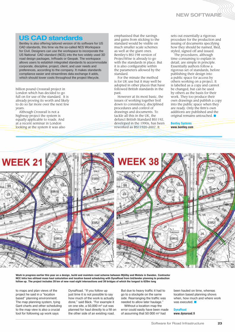
Finnish software specialist DynaRoad says that its latest civil engineering site planning software allows users to better tie site earthmoving activities to location.
“For civil and heavy construction being able to connect location to
the activity plays a central role of achieving the expected results,” said the DynaRoad software house’s business development manager Marcus Bäck.
All contractors particularly need to understand how different
activities in the same location affect each other, where most efficiently to send work teams once they have finished in a particular location, and for most road schemes how existing traffic will affect work flow.
“And there is also a need to communicate plans to all involved such as consultants, clients, and subcontractors,” he said.
Dynaroad as a planning tool for earthmoving in particular allows contractors to tie their schedules
Finnish expertise
▲
Software for Road Infrastructure 23
NEW SOFTWARE
emphasised that the savings and gains from sticking to the standard would be visible on much smaller scale schemes as well at the giant ones. Bentley’s BS1198 version of ProjectWise is already to go with the standards in place. But it is also configurable within the parameters allowed by the standard.
For the minute the method is for UK use but it may well be adopted in other places that have followed British standards in the past.
However at its most basic, the issues of working together boil down to consistency, disciplined procedures and control of drawings and documents. To tackle all this in the UK, the defunct British Standard BS1192, developed in the 1990s, has been reworked as BS11920-2007. It
sets out essentially a rigorous procedure for the production and issuing of documents specifying how they should be named, filed, styled, signed off and issued.
The procedures, although time-consuming to explain in detail, are simple in principle. Essentially authors follow a rigorous set of standards, before publishing their design into a public space for access by others working on a project. It is labelled as a copy and cannot be changed, but can be used by others as the basis for their work. They too produce their own drawings and publish a copy into the public space when they are ready. Only the firm’s own additions are published and the original remains untouched. ■
Bentley Systemswww.bentley.com
billion pound Crossrail project in London which has decided to go full on for use of the standard. It is already proving its worth and likely to do so far more over the next few years.
Although Crossrail is not a highway project the system is equally applicable to roads. And at a recent seminar in London looking at the system it was also
to maps and plan views of the project he said in a “location based” planning environment. The map planning system, tying Gant charts and other scheduling to the map view is also a crucial tool for following up work says
DynaRoad. “If you follow up just time it is not possible to say how much of the work is actually done,” said Bäck. “For example it on one site, a 50,000 m3 cut was planned for haul directly to a fill on the other side of an existing road.
But due to heavy traffic it had to go to a stockpile on the same side. Rearranging the traffic was needed to allow later haulage.”
Without a location map the error could easily have been made of assuming that 50 000 m3 had
been hauled on time, whereas location based planning shows when, how much and where work was executed. ■
DynaRoadwww.dynaroad.fi
Bentley is also offering tailored version of its software for US CAD standards, this time via the so-called NCS Workspace for Civil. Designers can use the workspace to incorporate the US National CAD standard (NCS) into the two widely used 3D road design packages, InRoads or Geopak. The workspace allows users to establish integrated standards to accommodate corporate, discipline, project, client, and user needs and preferences, according to the company. It makes standards compliance easier and streamlines data exchange it adds, which should lower costs throughout the project lifecycle.
US CAD standards
Work in progress earlier this year on a design, build and maintain road scheme between Mjölby and Motala in Sweden. Contractor NCC Infra has utilised mass haul calculation and location based scheduling with DynaRoad from bid/tender planning to production follow up. The project includes 28 km of new road eight intersections and 39 bridges of which the longest is 620m long

more formally a sketch pad with a more rigorous tool. Autodesk tool tackles that by providing a means to both work up concepts on an accurate canvas of the proposed development area, and then to provide them with a landscaped and rendered context.
The program can import a variety of background and contextual information drawn from the whole range of sources now available from map and digital terrain models from the Internet, Lidar surveys, rasterised aerial photography, GIS data and CAD. It has been developed from the company’s old Land XML package and allows users to bring together a fairly wide range of data and information in a variety formats to form the foundation for exploring design options. From these typical starting points the program can fuse the date to build up an environment into which data on buildings, street patterns and can also be integrated.
With this material a basic 3D model is created on which it is
then possible to draw a variety of alignments and specified areas with some fairly quick and easy point, drag and click tools. With a cabinet of styles these can be transformed into various types and widths of roads or railways, easily changeable as required.
These road lines “fit themselves” into the landscape, making cuttings and embankments, inserting bridges where needed to cross valleys and giving a quick indication of what a road will look like in that position. They can be dragged and moved around for adjustments. Below ground infrastructure can also be added such as drainage or other pipelines and power lines can be placed above the road, by drawing lines in the model or by importing information from CAD and GIS systems.
Alongside the road buildings can be positioned either as drawn outlines or as fully designed structures imported from programs such as Autodesk’s Revit or other programs and positioned by dragging and dropping into position. A series of tools allows road lines, or railways, to be sketched and perhaps moved around on the environment, automatically forming cuttings and bridge crossings if the terrain drops away or rises. The alignments can be modified with a variety of styles such as single track or dual lane road with or without pavements, or street lights.
It is also possible to move the model out into a more detailed tool like Civil-3D to allow fine adjustments to be made on some of the elements, such as the underground pipes, if required explained UK Autodesk civil engineering product specialist Jack Strongitharm.”All the 3D data for the program is stored in an SQLLite database which is embedded part of the program,” he said. The result is a fairly rapidly responsive program.
Other features like
The new Infrastructure Modeller from Autodesk is a new tool which aims to fill the gap in the design sequence when ideas are being explored and alignments tried out.
Before anyone sits down with the powerful design tools now available, be they BIM capable or not, there is an early process in design when these concepts and alternatives need to be explored, what-if’s worked through and broad “in principle” decisions taken. This is sometimes done purely as a “back of the envelope” exercise or with pencil on plans and maps. Or it might be done with general sketching tools which have become available on the Internet. But for infrastructure like roads getting a realistic and detailed impression of proposals has still meant working them up in the mainstream design packages to produce models that can be rendered and presented to clients or other designers. It can use up time on expensive systems and needs detailed work. The program is intended for the sketching and conceptualisation replacing as it were, the back of the envelope or
Modelling toolA new tool just launched by Autodesk gives designers a precision sketching tool for early concept and planning and then realistic visualisations
24 Software for Road Infrastructure
NEW SOFTWARE
Data from an array of sources can be used in Autodesk’s new Infrastructure Modeller design sketching package
Software for Road Infrastructure 25
NEW SOFTWARE
angle including below ground. “This makes it a very useful tool for showing clients and others the prospective design,” suggested Strongitharm.
But the quickness and ease of the program is also highly suitable for working through multiple scenarios and what-ifs and for functions beyond normal road and highway planning. “You can use this for working out temporary road patterns and site layouts for rock festivals and such events,” he said.
If required the stored model, which is held within an SQLite database which is part of the software, can be accessed from a more complex program such as Civil 3D where detailed elements can be added or the sketchy beginnings can be refined and developed. Northern European technical sales manager for Autodesk John Allen said, “It is highly scalable and can deal with very big datasets.”
It is a tool that architects and
others can use to sketch in road layouts around their projects to set context and generate initial thoughts. Beyond initial thoughts, the compatibility of the output with 3D modelling tools like Civil 3D allows the initial sketch to be imported along with its background data. A much more precise and detailed design can then be worked up from the initial idea. The program costs substantially less than the mainstream programs and will undoubtedly find a place. For the moment the program is available in English though other language versions will follow. Likely developments include a “sharing” option via the Internet which will allow remote users to modify or discuss and comment on ideas. ■
Autodeskwww.autodesk.com
watercourses, vegetation, and buildings can be placed into the developing model which is displayed as a 3D image. The tools allow the sketching in of lakes and water bodies, or perhaps forested areas and these can be populated with images of trees and other objects to increase realism. The program also allows underground objects like pipelines to be placed and has a transparency option to let them be seen. The program is aimed at those who either are not concerned with, or are not yet ready for detailed design and allows fairly easy modification, iteration and changes so that various options can be explored, assessed or explained to others. From the opposite point of view, areas which are protected by environmental rulings for example, can be imported in GIS form to ensure they remain undamaged.
As with many other 3D programs, the model when being worked on or complete, can be viewed by a fly through from any
“
”
The program is aimed at those who either are not concerned with, or are not yet ready for detailed design and allows fairly easy modification, iteration and changes so that various options can be explored, assessed or explained to others
Celebrating 25 Years as the worldleader in noise mapping software.
KEEP A LID ON NOISE!
Learn more SoundPLAN advantages. Call or click today. +1 360 432 9840www.SoundPLAN.com
SoundPLAN noise modeling software’s detailed graphics and comprehensive report capabilities help you:
One model for all sizes eliminates hidden costs and expensive upgrades. Now featuring Google Earth interface and full 3-D solid model view.
FREE subscription to ITS International
Guarantee your copies of ITS Internationalby registering for FREE online @
l V
ol.1
7 Issu
e N
o.6
Nove
mber/D
ece
mber 2
011 w
ww
.itsinte
rnatio
nal.co
m
www.roplreg.com
ITSIn
ternatio
nal
Vol.1
7Issue
No.5
Septem
ber/
Octo
ber
2011

The initial tool was developed further by an independent house and then bought some years ago by Causeway, “…which has put about four years of development into it,” said marketing manager Barry Blake.
At the heart is the Volumetrics module for inputting survey and map data and outputting data, in a variety of sources. PDS Volumetrics is an open system supporting all of the common survey data formats including 2D co-ordinates with textual level data and digital models produced by other software.
On top of that can be added two modules for road alignment design, which as well as the original cut and fill capacities include many features of modern road design such as DTM production contouring, interactive horizontal and vertical alignment, violation checks against user defined criteria, varying width single or dual carriage ways and surface analysis. “This was intended to be a more budget orientated alternative to the well-known MX,” said Blake. It works with user defined design and
parameter files.The program also has some
parametric capacity he says. It will also have dynamic alignment editing and will carry out automated updating response to design changes. By adding a second specifically highway design module to the basic alignment design module, complex roundabouts, slip roads and split carriage ways can be created. Transition curve design also becomes possible.
A final module, Layout Design, allows sketching of developments, carparks, local road networks.
But drainage network capabilities can also be added in, via an agreement with Micro Drainage WinDes, for which Causeway is both seller and reseller. The Micro Drainage product itself is modular adding additional capacities as needed with a core module handling storm, foulwater and combined drainage, network development and schedules for pipelines, manholes and setting out data.
The road marking, sign and swept path modules are combined as Causeway Traffic but are also separately available. Just developed for the software in version 18.1 is a virtual reality drive through representation of the design model which runs in AutoCAD or as a stand-alone. “This can be used for site meetings, design explanation and collaboration, client representations, and clash detection,” said Blake. “It will take in accurately information from the sign module and show you a physical representation of the sign allowing you to check its physical impact on other road features for example” he says.
For the moment the Causeway software is marketed primarily in the UK and areas used to British based standards. ■
Causeway Technologieswww.causeway.com
The software modules are designed to work in AutoCAD but are also complementary to the company’s Professional Design Suite (PDS) aimed at highway and infrastructure designers and finding increasing use in small and medium size firms. It is a parametric string based design tool for road corridor creation and now with a number of other modules associated with it.
The software is a modular package based on software originally developed for UK contractor Laing for cut and fill calculations on road alignments.
PDS suite expands in UKA suite of tools for road lining work, sign creation to national standards and vehicle swept path analysis has been launched recently by the Causeway Technologies software group which also makes collaboration software
26 Software for Road Infrastructure
CAD
Causeway Technologies offers an array of road marking, sign and swept path modules in its new Causeway Traffic package
Highway layout is placed in context with geographic contours

Software for Road Infrastructure 27
CAD
“”
We currently have 220 third party applications listed on our web site and are in contact with 600 providers altogether
Alternative CAD optionsA number of alternatives exist, at various levels, to the best known mainstream design and drawing packages. Some compete across the board and some are aimed particularly at smaller firms and those concerned about resources in tough economic times. World Highways rounded up a few.
The Bricsys software house in Belgium has been making headway in recent years with its Bricscad and a new version v12 just released should help it move forwards.
“The major advantage we have is that we work in a .dwg file format environment,” said creative developer Sander Shearis, “…which means that people using the software do not have to swap file formats when they move a drawing on to do other work.”
The software has the capacity to create a 3D model from a 2D layout directly without needing to change programs he said, and is a novel feature of the software. The 3D model remains in .dwg format.
Drawing in 2D in the basic edition and 3D modelling in the higher end Platinum edition can be done with constraints, an important new addition to the latest v12 version of the software launched in October.
It is a software add-in made possible by the recent acquisition of intellectual property rights for a variety of software components from Russian company LEDAS. Among other things the Belgian firm’s parent company Menhirs bought LGS 2D, LGS 3D, Driving Dimensions, RhinoWorks, and
other programs used by the computer-aided design industry. The 3D constraint solver allows users to parametric 3D constraints to edges, faces, and to several types of 3D solids. These are added to a constraint control panel in a manner similar to 2D constraints. Users can view constraints in the model simply by selecting them in the panel.
The new v12 also has a special cursor tool that automatically highlights lines, faces and other features and which reduces the number of clicks required for 3D manipulation, he said. Additionally the capacity of the program to handle large raster files has been greatly improved said Shearis, “And we have a new pdf engine to allow a drawing to be built up from an imported pdf used as a background.”
These features will improve the Bricscad base program as a platform for numerous third party programs which Bricsys has made a point of building up, including a variety of road focussed tools and additions.
These include among others Autoterrain, DTM Software, Sivan Design’s CivilCAD road design program and Swedish Simtra’s swept path program PathPlanner R4.
Two other swept path programs come from Germany’s RZI Software offering EasyTrack, and from Below software, the latter also offers a variety of other packages including street layout planning using kerb constraints. From the UK there is Key TerraFirma with ground
Engineers using CAD and other design technologies now have many packages to choose between
modelling, land survey and road and 3D design.
And there is even a point cloud plug-in which Indian software publisher Sycode declared will, “…give Bricscad the ability to reconstruct the geometry of an object from a point cloud.”
“We currently have 220 third party applications listed on our web site and are in contact with 600 providers altogether,” said Shearis. “Very often these are applications used internally by a company for some specialised purpose.”
He said Bricsys tries to encourage the add-ins and provides a free API and development kit, “…and a copy of Bricscad too for free so that they can test out their application.”
A lot of users are trying to encourage smaller software houses to port their applications to Bricscad as well as the more well-known platforms he says. “The cost of a Bricscad seat is only €500 or so (€750 for Platinum) which is much less than the mainstream programs and so it allows smaller plug-ins and add-ons to be run economically – whereas a mainstream CAD program might be three times the price of the plug-in itself.” ■
Bricsyswww.bricycs.com
DTM Softwarewww.dtmsoftware.com
Key TerraFirmawww.keycivil.com
RZI Softwarewww.rzi.de
Simtrawww.simtra.com
Sivan Designwww.sivandesign.com
Sycodewww.sycode.com

it was something to avoid on further schemes.
To try and ensure a perfect result on the latest scheme Atkins is deploying a 3D visualisation tool it has been developing in-house for some years. Based on widely available gaming type software, it allows the multiple components of the design to be brought together in a well-rendered three-dimensional model.
The software then allows an operator to drive anywhere within the model to check on sight lines, visibility and legibility of signs and signals, all of which are developed in software packages to the appropriate British standards and display the correct lettering, colours and so forth.
Importantly, the model allows the field of view of camera positions to be checked out, for road curvature, and for obstacles including trees perhaps, and particularly through the additional road furniture being added to the scheme.
The model is built from various components, both 2D drawings and 3D surface models brought in from AutoCAD and Microstation, Bentley MX and drawings of services and communications. “We get all
kinds of input including PDFs and historic data and convert all that to 3D and match the various elements in the model,” explained Phil Bromilow, a technician with Atkins on the project. Lighting is added too and signage generated by AutoSign.
The model was developed by Atkins inhouse team led by IT specialist Hugh Woods, using VRML, which is an easily available virtual reality language.
Other types of software can do this too and it is a rapidly growing use of BIM technology. But a key feature of the Atkins model is that elements can be adjusted “on-the-fly” so that major features can be moved and adjusted to clear sight lines, or perhaps camera positions can be altered.
“The virtual versions of the gantries or cameras can be clicked on and moved up and down, or along the chainage,” said Bromilow.
This is highly useful in meetings and discussions said Dalley. “There are plenty of potential clashes. We have 25 new superspan gantries for signs and equipment going across the road, and another six long span cantilever gantries for example.”
Another dozen existing concrete gantries and six existing
Work by joint venture contractor BAM Nuttall and Morgan Sindall will upgrade the hard shoulders of the dual three lane road to carry full traffic loads, allowing them to act as additional lanes at peak traffic hours.
The conversion is the third such scheme in England which has elected to increase capacity on particularly congested highways by “managed” motorway installations rather than widening the roads, or building new parallel routes. The solution avoids the expense of full-scale reconstruction schemes, needing costly new land take and major works.
Managed motorways use a complex of road instrumentation, traffic flow measurement and camera surveillance to monitor the road use constantly and then bring additional lanes into use and back out as required by peak traffic loads and speeds. To do so there is an equally dense array of traffic signalling, lane control and adjustable speed limits, variable message signs, and police and road agency intervention.
A series of intermittent emergency lay-by areas are added to the road at 500m intervals, to provide for breakdowns, and surveillance for stopped vehicles or obstacles is stepped up.
Fitting all this equipment into the road and ensuring that it can provide full visual coverage, and that signs can be seen clearly, is a major challenge for such schemes. For a first project on the M42 around Birmingham, the success of which has led to further projects, there were some difficulties with visibility and sight lines.
“Particularly on curves it was found there were a few gaps in the visibility of the CCTV cameras,” said consultant Atkins senior project manager for the M62 work, Alan Dalley. Though not critical,
Interactive visuals for CCTVA tailor made 3D visualisation system is being used by Atkins for a controlled motorway scheme in the UK. A major contract began in October to convert the M62 motorway in the UK to controlled traffic operation and will run until 2013. The highway links the two large northern cities of Leeds and Manchester, and is jammed solid at peak times with both long distance and commuter traffic
28 Software for Road Infrastructure
VISUALISATION & SIMULATION
Traffic flow and road maintenance issues can be assessed
Details such as roadside structures can be included

Software for Road Infrastructure 29
VISUALISATION & SIMULATION
said. “We can also help out the contractor with some temporary road layouts and the camera positions for those,” said Dalley.
The model is also capable of being taken in to Navisworks he said, which allows for automated clash detection in a physical sense, where components might be overlapping. The Atkins software is constantly evolving
says Bromilow who says the language for it is relatively easy to grasp, “…and works like Visual Basic.”
The €173 million (£150 million) upgrade scheme continues until 2013, in five phases along a 25km section of the motorway, beginning at Leeds and cascading the works westwards. Phases will overlap. ■
superspan gantries are being refurbished.
Cameras have to be placed in enough locations to give an overlapping field of view so that any problems or breakdowns can be spotted before switching to hard shoulder running for example.
The software is “operated” in meetings by Bromilow, though he said it is fairly simple to alter positions of items. It is serving multiple purposes. Firstly it aids the designers especially with line-of-sight issues, because previously this would have to be done with 2D plans. “Any changes would be painstaking and require altering things and then going back to examine how they worked,” he said. Repeated iterations could add to time substantially.
But it is also very useful for interactions with various stakeholders he says, particularly the police, road operations team and emergency services who worry about how the system will feel and what obstacles it might create for them. It is also good for public consultation and especially concerns about the impact of the road changes, and even individual concerns can be addressed he
“
”The program provides an effective visualisation tool for underground utilities
An overview of the project gives designers and engineers greater understanding of the scale of the work
A series of intermittent emergency lay-by areas are added to the road at 500m intervals, to provide for breakdowns, and surveillance for stopped vehicles or obstacles is stepped up
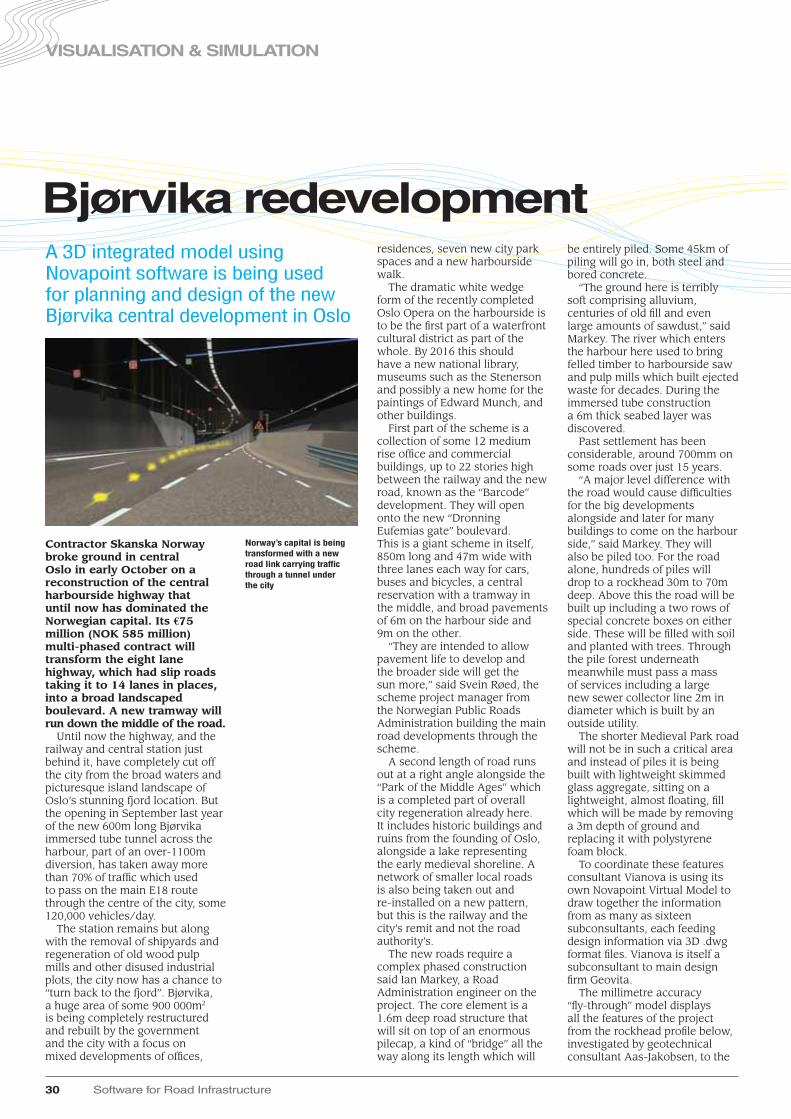
residences, seven new city park spaces and a new harbourside walk.
The dramatic white wedge form of the recently completed Oslo Opera on the harbourside is to be the first part of a waterfront cultural district as part of the whole. By 2016 this should have a new national library, museums such as the Stenerson and possibly a new home for the paintings of Edward Munch, and other buildings.
First part of the scheme is a collection of some 12 medium rise office and commercial buildings, up to 22 stories high between the railway and the new road, known as the “Barcode” development. They will open onto the new “Dronning Eufemias gate” boulevard. This is a giant scheme in itself, 850m long and 47m wide with three lanes each way for cars, buses and bicycles, a central reservation with a tramway in the middle, and broad pavements of 6m on the harbour side and 9m on the other.
“They are intended to allow pavement life to develop and the broader side will get the sun more,” said Svein Røed, the scheme project manager from the Norwegian Public Roads Administration building the main road developments through the scheme.
A second length of road runs out at a right angle alongside the “Park of the Middle Ages” which is a completed part of overall city regeneration already here. It includes historic buildings and ruins from the founding of Oslo, alongside a lake representing the early medieval shoreline. A network of smaller local roads is also being taken out and re-installed on a new pattern, but this is the railway and the city’s remit and not the road authority’s.
The new roads require a complex phased construction said Ian Markey, a Road Administration engineer on the project. The core element is a 1.6m deep road structure that will sit on top of an enormous pilecap, a kind of “bridge” all the way along its length which will
be entirely piled. Some 45km of piling will go in, both steel and bored concrete.
“The ground here is terribly soft comprising alluvium, centuries of old fill and even large amounts of sawdust,” said Markey. The river which enters the harbour here used to bring felled timber to harbourside saw and pulp mills which built ejected waste for decades. During the immersed tube construction a 6m thick seabed layer was discovered.
Past settlement has been considerable, around 700mm on some roads over just 15 years.
“A major level difference with the road would cause difficulties for the big developments alongside and later for many buildings to come on the harbour side,” said Markey. They will also be piled too. For the road alone, hundreds of piles will drop to a rockhead 30m to 70m deep. Above this the road will be built up including a two rows of special concrete boxes on either side. These will be filled with soil and planted with trees. Through the pile forest underneath meanwhile must pass a mass of services including a large new sewer collector line 2m in diameter which is built by an outside utility.
The shorter Medieval Park road will not be in such a critical area and instead of piles it is being built with lightweight skimmed glass aggregate, sitting on a lightweight, almost floating, fill which will be made by removing a 3m depth of ground and replacing it with polystyrene foam block.
To coordinate these features consultant Vianova is using its own Novapoint Virtual Model to draw together the information from as many as sixteen subconsultants, each feeding design information via 3D .dwg format files. Vianova is itself a subconsultant to main design firm Geovita.
The millimetre accuracy “fly-through” model displays all the features of the project from the rockhead profile below, investigated by geotechnical consultant Aas-Jakobsen, to the
Contractor Skanska Norway broke ground in central Oslo in early October on a reconstruction of the central harbourside highway that until now has dominated the Norwegian capital. Its €75 million (NOK 585 million) multi-phased contract will transform the eight lane highway, which had slip roads taking it to 14 lanes in places, into a broad landscaped boulevard. A new tramway will run down the middle of the road.
Until now the highway, and the railway and central station just behind it, have completely cut off the city from the broad waters and picturesque island landscape of Oslo’s stunning fjord location. But the opening in September last year of the new 600m long Bjørvika immersed tube tunnel across the harbour, part of an over-1100m diversion, has taken away more than 70% of traffic which used to pass on the main E18 route through the centre of the city, some 120,000 vehicles/day.
The station remains but along with the removal of shipyards and regeneration of old wood pulp mills and other disused industrial plots, the city now has a chance to “turn back to the fjord”. Bjørvika, a huge area of some 900 000m2 is being completely restructured and rebuilt by the government and the city with a focus on mixed developments of offices,
Bjørvika redevelopment
30 Software for Road Infrastructure
VISUALISATION & SIMULATION
A 3D integrated model using Novapoint software is being used for planning and design of the new Bjørvika central development in Oslo
Norway’s capital is being transformed with a new road link carrying traffic through a tunnel under the city

“”
Software for Road Infrastructure 31
VISUALISATION & SIMULATION
The various elements are georeferenced and follow a component naming convention that allows the model to automatically recognise new design features as they are added he says. Once entered, “…it rebuilds in about 20 minutes.”
The update work is still necessary in version 18 of Novapoint’s road software suite, though when the new version 19 based on a 3D database model begins to mature, it will be possible to use the Virtual Model directly from the database, rather than import and marry up the data.
The model has been very useful for planning and design modification said Røed. It gets passed on to the contractor with all the geometric details “and he can extract what he needs,” he said, though specific information on reinforcement materials specifications and the like is still extracted from drawings.
The next stage using the model is to build representations showing the various phases of
the construction and temporary works. Keeping the traffic flowing during the rebuilding of the road is a crucial element and it will help with that and other logistical aspects. There is the impact of archaeology ahead of construction to phase in as well. The area has already proved rich in medieval finds during tunnel construction.
The phase models are being done separately because there are so many layers in the model that to include all the information in the main model would create a gigantic visual clutter said Fremnesvik. Currently he is working on phase one and expects to do other critical phases from the 10. “But those can be built by copying the first phase and then altering it,” he said.
The €75 million road project will continue until 2015 when the tram lines are due to go in and the whole area will have been regenerated by 2016. ■
Novapointwww.novapoint.no
best starting point allowing a visualisation to be created with, “…millimetre accuracy,” he said.
His current project has been a simulation of a station in Hong Kong for the mass transit system, but he says the same principles apply to highway structures.
In the test program users are presented with a three dimensional view of a station which can be navigated using a joystick, so that they can walk through it, and “see” it exactly as it will be. To make the experience as immersive as possible, a three screen display is used.
These tools are just an extension of visualisation. But the advance with this package is apparent when the user is asked to do tasks within the virtual model, such as finding their way to platform 3, or the ticket office. They begin from a fixed point and can be timed, their hesitations and errors in finding their way all recorded.
Because the signage in the model and the line of sight to it, the spaces, the obstacles such as ticket barriers, are all
represented accurately, they can be modified and adjusted, and the impact measured. The designers get feedback from the design output which can be used to modify the input.
“In this way visualisation is not merely looking to mitigate the worst effects, such as light spillage on a highway, but to tune a design for the best possible experience,” said Simondetti.
To make this work well, a large number of users have to be measured and perhaps re-measured when adjustment are made. That requires that the system is easily accessible for many measurements.
“The software we are using allows this to be done on an ordinary portable laptop computer,” said Simondetti. “Effectively we are simply ‘publishing’ the BIM model in the same way as a PDF publishes documents. There is a variety of software available to do that,” he said. The target is to put the model onto the web so that thousands of users, or more, can provide input. ■
terrain surface and various parts of the road structure.
Buildings and vegetation are displayed, lighting and signs and under road services. The sewer line is there, buildings – either in detail or as outline for as yet unbuilt structures on the harbourside, and structures like an existing bridge crossing of the railway. A new road crossing at the end of the project is also included which will allow partial closure of the old one, which is being dropped down to ground level for half of its length. All these different components can be switched on and off for viewing and understanding the design, in progress meetings or for clash detection.
“There are 20 or so design models that are brought together and another dozen or so for defining the scenery,” said Vianova road engineer Morten Fremnesvik, who is tasked with coordinating and updating the Virtual Model from its various components, as designs develop. He does this alongside his main road design work.
The use of interactive visualisations built on 3D design models has been under development for some time. They provide a way to demonstrate projects and their impact to the public, clients and other parts of the construction team and have been used in public information displays for major projects like the M1.
Multidisciplinary consultant Arup has been taking the concepts further using the kind of software used in video games and combining it with data collection mechanisms. The aim is to measure precisely how a design works by seeing how users respond to it. “There is a big difference between simulating behaviour in a situation and measuring real behavior,” said Alvise Simondetti who is visualisation project leader at the consultant’s London headquarters.
If you build an accurate enough model with all the features of a design within it, you can get users to “walk” through it, or perhaps drive through it, he explained. Obviously the BIM model is the
There are 20 or so design models that are brought together and another dozen or so for defining the scenery
Morten Fremnesvik:Vianova road engineer
Visualisation as design feedbackA portable visualisation tool developed by Arup is helping designers get quantitative feedback into their designs
New technology has been used in public information displays for major projects like the UK’s busy M1 motorway

supported by visual cues such as signs and road markings. An interactive 3D virtual reality simulation was seen as the most efficient way to assess and incorporate driver behaviour into the design process.
The simulation needed to test what type of signage would give drivers an awareness of their location and speed, as well as a sense of the vertical gradient.
In addition, the highway signs had to indicate clearly what lane drivers had to be in to leave at their desired exit.
The range of ‘what-if’ driving scenarios required a full 3D visual interactive computer simulation rather than simpler animation. UC-win/Road software was able to provide a platform for real-time simulation.
Visualisation software has become widely used as a technology for explaining and publicising major road and highway schemes both to clients and to the public in consultations and planning inquiries. It has grown increasingly realistic. But increasingly visualisation is finding practical application to feedback into the design process.
One major project has recently been carried out in Tokyo for example, using the increasingly widely used 3D visualisation software produced by Forum 8. Its UC-win/Road software has been extended into driving simulation and this capacity made it highly useful for an extremely complex road junction in the Japanese capital.
The extraordinary Ohashi junction is a three way junction for the greater Shuto Expressway and it is configured as a multi-storeyed spiral tunnel in the middle of the urban landscape. The structure allows designers to minimise the space required for the complex interchange but its highly unusual configuration raised major concerns about driver responses.
The junction comprises a 4-tiered spiral that drops in elevation by about 70m and drivers coming into it will drop or climb a steep curve. While doing that they have to decide rather quickly the direction they will go to access the highway. Designers were concerned drivers would find locating the right exit to be too difficult and this might be a hazard to themselves and others. Signage and road markings would be critical to give visual cues.
To test out the options the team turned to the consultancy side of Forum 8 to run virtual driving trials in realistic conditions using 3D visual interactive drive simulation. This difficult tunnel driving environment was the impetus for examining how drivers can be best
32 Software for Road Infrastructure
VISUALISATION & SIMULATION
Driving simulation for road designAn extraordinary junction in Tokyo has used 3D driving simulation to help its design
A new junction in Japan’s capital Tokyo has benefited from the use of novel visualisation technology during its design
Designers were able to evaluate the behavior of drivers navigating a visualisation of how the junction would look to determine layout
The emergency exit provisions were thoroughly evaluated
Using the visualisation, the designers investigated how drivers would interpret roadmarkings

Software for Road Infrastructure 33
VISUALISATION & SIMULATION
The software originally was used to visualise alternative road designs but over a decade has developed to include: 3D CAD and digital terrain models; environmental conditions; time of day and season effects; and global location.
Combined with traffic simulators like S-Paramics and pedestrian simulation it can show animated traffic and human characters.
The visualisation has been combined with driving simulator hardware and software to mirror vehicle dynamics of individual cars, which allows not only training but assessment of driver behaviour.
For this project driving trials were held in two series separated by a period of six months. Subjects were first acclimatised to the simulator with a sample road and then pre-programmed scenarios were used to expose subjects to various stretches of the junction.
A variety of road markings, signs and wall designs were used. These included sidewall signs in blue and red, triangular wall surface markings, overhead signs relaying exit distances and overhead warning signs. The blue and red road markings were used to represent different exits off the junction.
Logs of the drivers’ responses as well as surveys were kept. Each car’s instantaneous position, lane centre offset, speed, and acceleration were extracted from the simulator system. Surveys asked participants about sign visibility, clarity of exit directions, and preferences for colour and design.
Adjustments were made and then tested in the second series of trials. The outcome was positive and designs have been incorporated into the actual junction a few months ago. ■
Forum 8www.forum8.euwww.forum8.com
A series of overviews allowed the design team to look at the entire project in detail

and what software tools might be needed by contractors, designers and the supply chain is even more complex. As one expert in the field, UK consultant to software producer Bentley Systems Phil Jackson said, there is a kind of “fog” around the subject and a host of competing definitions. “At present what BIM is really depends who you are in the construction chain and what you want to do with the software tools,” he said.
So, variously, it can be seen as a 3D design tool; a tool for multi-disciplinary collaboration in design; a tool for collaboration in construction, bringing various subcontract disciplines together to coordinate work; a planning and sequencing tool; a clash detection tool for both spotting overlaps in physical space and in project sequencing; a communication tool for engineers to speak to each other and also to the client; a publicity tool using visualisations; an information transfer tool, which is possibly one of the most important aspects; a life cycle information tool where the greatest benefits could be achieved; a design costing tool and construction financing tool, and importantly too, a health safety tool allowing site works to be run through and organised with reduced risks.
Such a wide range of functions, and others, is inevitably hard to get a grip on. It draws on and uses all kinds of software from structural and road design packages and data federation tolls like Navisworks to relational databases. But as speakers at the Institution of Civil Engineers conference in London recently, were keen to emphasise, it is not focussed around particular kinds of software or even the output from software. One speaker, Rachel Arulraj, the director of virtual construction at US consultant Parsons Brinckerhoff said that the firm uses over 45 different
software tools to enable BIM.Instead it is really about the
process of design, construction, and maintenance. “Building in BIM is a verb, not an object,” was a point repeatedly made at the ICE conference and that means building roads as much as it does office blocks. But despite that, to grasp what BIM is, it is helpful to focus on one type of software to start with, which emerged in the building and architectural sector. This is the object-based 3D “intelligent” model.
Such models started as computers exponentially grew more powerful, and the increased sophistication of CAD allowed 3D models of a structure to be drawn. “Pretty rapidly people realised that this was not enough and they needed software that worked in object-based terms,” said Nick Nesbit, from AEC3, an Anglo-German consultancy specialising in BIM. He is also a leading figure in the development of international data standards for BIM.
“What that means is that a 3D design is not just adding a Z coordinate to drawn lines, but that there is a complete reorganisation of the software to use a set of parametric objects. Such objects have all kinds of properties and attributes. Most of all they can ‘relate’ to each other,” he said.
The archetypal programs of this type are those like Revit, now owned and developed by AutoDesk in two flavours: for architecture and for civil structures, or the equivalent Bentley Architect, ArchiCAD and others. In these, designers use objects they set up and define themselves, or draw in from a library, or as the market develops even from outside sources like manufacturers.
To a greater or lesser extent these will automatically, or with changes to the dimensions, “self-fit” into a structure. A “window” for example will have adjustable dimensions and information
After half a decade of slow development in road engineering, everyone suddenly wants to talk about Building Information Modelling: the use of electronic models in construction. Consultants have got “BIM champions”, software sellers are branding their products upfront as crucial “BIM tools,” and clients are beginning to insist on BIM “deliverables”. These include some governments, notably in Scandinavia, Australia, and lately the UK, and various states and federal bodies in the US such as the US Corp of Engineers. Others are working on it too.
The reason for this according to numerous experts in the field is partially technological and partially economic. BIM offers major efficiencies in the construction process at a time when the economic crisis is making that vital, competition is growing and clients becoming ever more demanding. “And meanwhile the maturing of the software products has reached a critical mass point,” said Adam Mathews, European and Middle East business development manager for AutoDesk, one of the sector’s leading vendors.
But pinning down just what BIM is, and is not, is more complex than it might appear. Understanding what is required
BIM takes offInformation modelling for roads and highways is taking off. But why now, and what is it anyway? Adrian Greeman
34 Software for Road Infrastructure
BIM
Using BIM effectively offers major efficiencies in the construction process at a time when the economic crisis is making that vital

Software for Road Infrastructure 35
BIM
designing overhangs on bus or train platforms. But they might indicate future development.
Novapoint in Norway is making more head-on progress towards full BIM with a new version of its road design suite being built around object-based principles and a full 3D model held in a database rather than as design files (see box). It could be the first civil engineering “Revit”.
Even in the structural sector there are advances to be made in object-based software before the full concept is realised.
But attaining this level does exhaust what BIM is by any means, far from it. Many other elements of what a full 3D model will allow can be done now, and by different means. Some of these have taken on a life of their own which is now almost more important than the original design function of the models. As a result BIM has expanded away from the design sector into the complete construction chain. “It is no longer ‘lonely BIM’ but ‘collaborative BIM,” said AutoDesk’s Mathews. A final stage will be, “…whole life BIM,” he said, when the model data is seamlessly passed on into the asset management stage.
First of the additional aspects is the use of a single model as a repository for the design work of others to be added to. It becomes a “single source of truth” for data and measurements and the location where all the elements of a design gradually build up, which allows different designers to coordinate and work together collaboratively. Using the ability
of a three dimensional model to be represented on screen, visualisations can be made which are millimetre accurate and allow clashes to be spotted, and the design outcome to be rethought after walking or driving a “virtual construction”.
The cumulative appending of design data to the model objects – which are defined to allow such additions, - also becomes one of the most important new capacities of BIM, because the “design intent” can be carried over to the construction phase said Richard Shannon, BIM “Champion” for UK international consultant Mott MacDonald. By querying the model, information can be provided to reduce site errors, and reduce RFIs.
Even more importantly, the data is carried on to the eventual commissioning and operations phase of a project. Not just design data is added; during construction further details are added in, such as reinforcement, and perhaps for the first time even completely accurate “as built” data. It all constantly feeds back into the design model as well perhaps allowing adjustments to reflect the FM team’s requirements better.
Other information is easily added as well such as specific details about components like drains or lampposts, beyond simply their alignments and dimensions. Each item can have its own particular serial number recorded and with that a host of information about what it is, where it was made and which batch, what maintenance it
about properties such as thermal insulation capacity.
It will also be moveable and as it is dragged and dropped, a walls and corners will “heal” themselves”, with a space made elsewhere to accommodate the object. Offsets and clearances will be seen too.
An equivalent program in civil engineering would see perhaps the capacity to select a “roundabout” from a pallet of junctions which could be dropped into position, said Mark Bew, technical director at consultant URS-Scott Wilson in the UK and a leading figure in the British government’s BIM working party. It would automatically connect onto the road and all necessary cut and fill would be done.
Object based design is the “Holy Grail,” he said and others agree. Arulraj for example said, “Full BIM will mean programs where objects will have attributes”.
That is some years off. Major problems have to be sorted out, not least in international setting of standards for what objects are, what information they should contain and so on. Software has to develop.
The international “Building Smart” groups have done major work producing such specifications which are known as Industry Foundation Classes, or IFCs, which are not proprietary software specific. But they are not well defined in the infrastructure sector. “Most vendors do not yet include them,” said Nesbit.
Road design programs like Inroads or Bentley MX, have long had three-dimensional surfaces and can cut through these and calculate road cuts and embankments. They are data based and volumes and quantities can be produced. But the objects within them do not “know what they are”. Even Autodesk’s Civil 3D which is partly constructed along object lines, and can quickly readjust and rebuild alignments and all the elements attached to them when they are dragged and moved, is not an object-based program in the full sense.
“But pay attention,” said UK Autodesk civils expert Jack Srongitharm, “We have recently introduced a new category of items to its design libraries called ‘solids’ which are a bit more than lines and surfaces. Currently solids deal with a specific design problem such as
“
”
Road design programs like Inroads or Bentley MX, have long had three-dimensional surfaces and can cut through these and calculate road cuts and embankments. They are data based and volumes and quantities can be produced
Causeway says that its latest software package offers intelligent 3D modelling capabilities and powerful integration functionality for civil engineers. Called the Professional Design Suite (PDS), the package is said to cover all aspects of earthworks design and quantification, development site infrastructure design and highway design. Modules are available for digital modelling, alignment design and drainage design. The latest generation also features a visual reality module that generates walk-throughs and fly-throughs
within just a few minutes of finishing a design.
The digital modelling BIM capabilities of PDS include borehole modelling, calculations from multiple models, automatic generation of formation models and quantities, storage pond modelling, dynamic cut and fill analysis and surface design tools. These are combined with horizontal and vertical route alignments, intelligent 3D junction design and dynamic integration with micro drainage.
When the design is complete the visual reality module uses gaming technology to
generate designs faster than with conventional methods. Causeway has also made a free viewer available to help clients view the designs.
PDS is said to be intuitive to use and can be learned with minimal training and with no requirement for specialist CAD skills. PDS users, who include the majority of the UK’s top 100 consulting engineers, typically report time-savings of 50% compared to traditional methods.
Causewaywww.causeway.com
Innovative BIM package
▲

being carried out more and more by software. One thread of this development is the consistent naming and organisation of documentation to rules of military precision, which is particularly represented by the UK standard, BS1192(2007). A tailored version of Bentley Systems’ ProjectWise works to this.
Another major aspect of BIM models is that they incorporate design work and information from a host of different disciplines in the one place, all coordinated with each other and
again BS1192 2 procedures help achieve this.
But perhaps the “killer app” for this is Autodesk Navisworks, and to some extent equivalent tools like Bentley Navigator which all bring together disparate designs in one place for virtual model display, matching files or in Bentley’s case holding them in a single “container”. Novapoint has its Virtual View module which draws road surface, lighting, signage, drains, cabling and lighting all into one model.
By “federating” data, matching up assorted 3D models and
requires, and so forth, all sitting in the model. Delivering this accumulating information in the BIM model to the client, means that projects will arrive with their own very specific electronic “user manual”. Data can then be fed directly into maintenance and facilities management, beginning to realise the dream of “whole life cycle” design and construction.
Many of the experts spoken to by World Highways put this aspect of BIM development at the top of the list. It is being driven especially by the rise of design-build-operate and perhaps own, contracts.
“The point of BIM in the end is outcomes,” said Shannon. “The client is interested in a better product and saving money.”
Part of that is better understanding of the design, which can be created in virtual form for discussion and modification, so that client-designer misunderstandings and misdirected expectations can be eliminated, and with them the need to change or re-do projects later.
But the biggest savings come in the use and maintenance lifespan of the project. Building up facilities management or road pavement maintenance information and data is expensive and if much of it is present at the start, including manuals, serials and place of manufacture for components, substantial effort could be saved. Rescans and resurveys which are routine now, could be ruled out.
“At present,” said Shannon, “by the end of a project everyone is tired or looking to move on. So the data, if it is passed on at all, comes as a great pile of photocopies and scraps.”
But the rigorous accumulation of electronic data which an object model facilitates, can also be done now with existing design and other software tools, even without the object-based model.
Developing a system to collect data and its attachment to design drawings and models is already in train. In the United States a protocol called COBie, the Construction Operations Building information exchange has been originated by the US Corp of Engineers which sets out how and what information should be gathered and presented in a text based form and it is gathering momentum. The UK government is building part of its own BIM strategy on COBie for example.
Early stages of BIM see this information collection running in parallel with 3D design work, with the capacity to automate it
36 Software for Road Infrastructure
BIM
The two lane Crussell Bridge in Helsinki, opened in June this year was a complete BIM project by design consultant WSP’s Finnish operation. The complex 175m long dual span assymetric cable stay structure, which links Ruohalahti and Jätkäsaari on the western shore of the city centre and carries vehicle traffic as well as having facilities for cyclists and pedestrians will also feature a tramway in the future. The City of Helsinki was the client and it was built by the contractor Skanska Civil.
WSP used a BIM set up for both concrete and steel design of longitudinally pre-stressed concrete beams including time and management dimensions. It was the consultant’s first experience of modelling concrete with reinforcement. The bridge was a pilot for both WSP and the client, and also software provider Tekla Corporation via its bridge design software, which has been further refined as a result of the scheme.
Tekla’s software is one of the few true BIM products around, believes WSP infrastructure BIM leader David Stone, “…in as much as it uses a full data-object methodology”.
Client, designers, contractor and major subcontractors all used the same primary BIM tool and the construction model was published on the WSP server. Extensive use was made of the BIM model for the fabrication of steel girders and concrete reinforcement, for monitoring and management of the supply chain of
fabricated components, for formwork and temporary support structure design, for quality control using laser scanning and for construction planning using 4D animation.
Tekla Softwarewww.tekla.com
Twin lane structureThe new Crussell Bridge in Finnish capital Helsinki was a complete BIM project by WSP and was built by Skanska, while the structure improves connectivity to the western shore area of the city - image courtesy of WSP’s Nicola Evans
▲

Software for Road Infrastructure 37
BIM
Atkins, have been using it on the huge widening and upgrade to London’s M25 ring motorway in advance of the Olympic Games.
“This is only partly down to the software,” Philp underlined. “A lot more of BIM is through the procedures and methods that the software facilitates.”
For this physical side of construction these site coordination aspects are more or less what they mean by BIM at present, highlighting Phil Jackson’s point that BIM has multiple meanings for different participants.
A further element that feeds into BIM at present is the general coordination of design work construction management and project managements, again around BS1192. Stuart Spencer, Bridge Information Model manager for Bentley Systems says the importance of that can be overlooked.
But others underline the fact that BIM has grown to embrace a lot more than software and object-based design models.
It is a transformation in ways of working, believe many in the industry. “It is very challenging,” said Jeff Stephens, a technology manager at the UK construction division of French firm Vinci, “and will be a disruptive change”.
So important is it that the UK government has set up a five year programme to introduce BIM working, drawing on these elements. The aim is to draw all firms, including the “trailing edge” of smaller supply firms and subcontractors, into using the technology.
Bew, who chaired the working party which advised the British Government, said that the aim is to achieve the use of assorted types of existing 3D modelling softwares, along with electronically managed file based collaboration, by 2016. The so-called Level 2 BIM in a hierarchy defined by the working group which ends with the “Holy Grail” level 3, of object-based systems in which all the data, both spatial and textual is held in one place.
The way that has to be achieved is left open in the British strategy to avoid plumping for any particular types of software. But a key element is the interoperability of data transfer, probably around IFC standards, and the development of COBie.
“Level 3” itself is still a future vision and there are some in the field who argue it can be achieved without producing the
all-encompassing single model, which could become so large it is unwieldy. Federating the data may be all that is needed say some, with advances in the kinds of programs that bring in disparate data. Others are more certain the way to go is the object-based model, including Bew. Norway and Finland are both already well advanced on that path, and Norway’s government already requires delivery of models built around IFC standards.
Software producer Novapoint has been working on the development of a database mediated 3D model software for about six years and is about to launch a first version. This will tie in with a giant model held by the Road Administration itself, to which future projects will be added, gradually building up a single representation of the country’s entire road network and the terrain around it.
The Norwegians say this is not unwieldy because any particular designer will only check out as much of the database as he needs for his project. But he will have access to all the past data on the road system, saving huge amounts of survey and other work.
Finland too is heading in this direction. For buildings, the government property agency has been requiring the submission of BIM models since 2007, again with inter-operability achieved through using IFC, said Jaakko Jauhainen, sales director for Solibri which makes software to verify BIM models and their rich information content before submission.
“The standards for infrastructure are less well developed but are on the way too,” he said.
One of Solibri’s big markets is the US which is pushing ahead with BIM usage. Several DoTs are now passing 3D models on directly to contractors for use in machine guidance systems, another major area of BIM development.
BIM is an idea whose time has come, a speaker told the London ICE conference. It seems so. ■
Autodeskwww.autodesk.com
Bentley Systemswww.bentley.com
Novapointwww.novapoint.no
sometimes 2D drawings as well, into a single view around a common reference, these programs replicate elements of what a full object BIM model will do and allow several key aspects of BIM working to be carried out.
Top of the list is clash detection and it is no surprise that the automated detector for overlaps and spatial intrusions in Navisworks, which alone can save tens of thousands of dollars, if not millions, in avoiding later physical conflicts, comes only in the premium version of the program.
But Navisworks in its viewing capacities has particularly taken off for contractors and on-site construction. Its ability to show the various elements of the design in a single walk through visualisation has been proving invaluable for site meetings, design exploration, subcontractor coordination, construction sequence run-throughs, and spatial planning for detailed site operations.
“It helps that although federating all the data requires the full program the result can be displayed in a free viewer,” said major UK and international contractor Balfour Beatty’s technical manager, David Philp.
Using the virtual views, drainage installers can make clear that they do not have sufficient working space, or concreters that the skip will not be able to lift over nearby falsework.
Extending Navisworks’ value for on-site work is the capacity to create sequence simulations and attach them to a timeline which can be run through with a slider. Further dimensions of financial costings such as payments received against outgoings, and lately the carbon usage of a project, are growing in importance too.
Other programs can add to these capacities too. Synchro for example can link a 3D visualisation to Gant charts, and to Primavera or Microsoft project manager timelines and calendars, and can allow quick resequencing of operations by dragging out critical path elements and so forth, with the result reflected in the 3D view. Some major contractors worldwide are taking to this.
One important aspect of this type of program is emphasised by Balfour Beatty and that is safety. Philp says that pre-visualisation has a major impact on safety for complex sites, allowing virtual construction to be carried out and obstacles to be identified before anyone can get hurt. The contractor, and partner consultant
“
”
Software producer Novapoint has been working on the development of a database mediated 3D model software for about six years and is about to launch a first version

38 Software for Road Infrastructure
BIM
Estonian company Nordecon, founded in the transition to a market economy in 1989 has been a major user of Autodesk software as it has gone from a small early start into one of the country’s major civil engineering contractors.
European money has helped it grow particularly as investment in modern infrastructure has been made, but like everywhere else the credit crunch of 2008 has seen competition grow tougher.
As part of its strategy to compete and keep up, the company has been making good use of modern software and particularly the AutoCAD Civil 3D package with its core 3D parametric design model, which Autodesk claims as the, “…building information modelling solution for civil engineering”.
According to Marek Suviste, head of the company’s design and geodesy division, this together with AutoCAD Map 3D has helped his team optimise designs quickly, saving time in coordinating and re-coordinating subsequent changes. Suviste added that a benefit of the software is that design data is kept in one file with the documentation. “Each is linked to the other. This is far simpler than using other software where the design elements and documentation are kept separately, often causing coordination problems and bottlenecks,” he said.
The company also has one licence of Novapoint software which the team use on top of AutoCAD.
The Autodesk software was at the centre of work on a recent road project, sections of the E263. It is Estonia’s longest road running from the capital Tallinn to Tartu and eventually onto Riga in Latvia.
The three-year project, completed last year, includes the Mäo intersection, a 6.2km section of two-way road with two lanes both ways, a 4.5km section of light traffic road, four overpasses and a
For contractors a large part of the interest in BIM is in planning and managing site operations and sequences of tasks, using the 3D model to visualise and coordinate site operations, placing and use of equipment and so on.
Time lining a gradually developing site can be done in Navisworks bringing in a matching various 3D design element models. But a tool designed specifically for this aspect has been increasingly taken up, namely Synchro’s Project Constructor.
It is described on its website
specifically as a “4D construction visualisation, project scheduling, advanced risk management tool which can synchronise with 3D design changes, supply chain management and cost allocation for comprehensive virtual construction simulation”.
The software, developed in the UK originally by a project management company is a kind of hybrid between scheduling software such as Primavera, now part of Oracle, or Microsoft’s project manager, and a 3D display program.
Its interface shows users three or more displays, one a listing of
Scheduling advance
Estonian road projectEast European contractor Nordecon has been moving towards BIM methodology to improve efficiency, such as a recent road project in Estonia according to software specialist Autodesk
bridge over the Vodja River.Few projects come without
their own challenges and this one was no exception. As Suviste explained, “Nordecon wasn’t the first to take on this work – it had been attempted before, but because of the low-lying nature of the road, it was permanently covered with water.”
Consequently the team first had to design a dewatering system before they started. To do this they used a proprietary Estonian program together with AutoCAD Civil 3D. “Because the local software was designed to sit on the AutoCAD platform, this was straightforward,” he added.
The road itself was modelled in AutoCAD Civil 3D. Via its capacity to automatically readjust the team could visualise their designs and then test and analyse them as if they were the real thing.
The software easily manages and coordinates changes, allowing experimentation with various iterations of the design without the huge amount of
work this would once have entailed. For example, during this project, engineers were able to compare the impact of different road surfaces on the design and analyse their durability.
They were also able to calculate accurately all volumes of materials needed from the model. The software recalculates these every time a revision is made, so there is always an accurate figure available. In this way “cut and fill” can be balanced as closely as possible to avoid unnecessary labour and resources.
Despite the economic squeeze Suviste said that there is still a lot of work needed for infrastructure in the region and he hopes that EU money will help maintain the momentum. But competition for work is bound to be strong. “However, with the software we are confident that we have the competitive edge,” he concluded. ■
Autodeskwww.autodesk.com

Software for Road Infrastructure 39
BIM
tasks and sequences, one a Gant like timelining and the third a 3D window in which a stylised design model is displayed.
The schedule is either created in Project Constructor itself or can be imported from a scheduling program such as Primavera; the 3D model is built up by importing a wide range of formats such as dwg. Like Navisworks, Synchro can spatially coordinate various files to show a complete image built up from a variety of matched design files.
A navigation cube allows this model to be rotated and viewed from assorted angles above and below.
By making sure that proper naming conventions have been followed for the model the elements of construction in the time chart above can be tied to the model so that as the construction schedule is run through, the 3D model below displays the various stages of construction.
These stages can be easily changed in the timeline by dragging the schedule blocks to and fro or expanding and contracting them. According to Synchro marketing manager John Razzle, this is a simple and quick way of rescheduling without having to build the timeline all over. If the schedule is changed then the new path through the project can be saved as a variant on the original schedule which is saved initially as a “baseline” schedule. “In this way you can adjust the schedule and what differences have been made,” he said, “…which either allows you to see the actual schedule against the planned schedule, to modify according to “as on site” realities, or to carry through “what if” changes very quickly, on the fly almost.”
Two versions of the 3D model and their associated timelines are displayed at once. More “baseline” variants can be saved too and brought up for comparisons.
The model allows a very visual display of scheduling that can be used in site and project management discussions to explore options or quickly measure the impact of delays. Using a free downloadable viewer the models and schedules can also be looked at elsewhere, perhaps to keep a client in touch, or for bidding purposes when clients are interested to know how things are
going to be done.By adding on construction
equipment components, the impact of where hoists and cranes are placed, or asphalting equipment or concreting crews, can be more easily grasped. A new feature of the software is the so-called Pathfinder that will describe the route of some equipment through the site and importantly the timing of its passage.
“The software allows you to pick up clashes between elements on site but it has an additionally important capacity to find time-related clashes” explained Razzle. “So it will tell you for example that moving a mobile crane into position might be impossible at a particular moment or only before or after particular operations.”
The software for the moment could be described as part of Level Two BIM but has enormous potential to pick up on the development of softwares using full object descriptions and the potential world of object based modelling. It will import from Revit currently for structures and recognises IFC formats.
Synchro’s CEO Tom Dengennis, emphasised that although the tool overlaps to some extent with Navisworks it is complementary rather than doing the same design review job “and there are moments when the schedule is sufficiently stable that a timeline built in Navisworks is the right thing.”
The design review could also be done with Bentley’s Navigator he added, and Synchro has a relationship with Bentley as well as with Autodesk. “But for flexibility and changes to sequences on site this is much more the right tool, focused on the delivery process. It can divide up a concrete or asphalting area into smaller sections for scheduling quite easily for example.”
Equally he says that the timelining does not replace the full scheduling and programming of Primavera, but works with it.
Synchro will also display a graphical view of cost information on site and value earned; it can also create user defined windows to graphically display other data. One such was used to display volume of storage space used at any one moment in a site laydown area which had a very limited capacity.
The program is being used on some very large projects including airport development in Los Angeles, the Shard high rise in London and others. Razzle added that it is equally suitable for highway work. ■
Autodeskwww.autodesk.com
Bentley Systemswww.bentley.com
Synchrowww.synchroltd.com
“”
The model allows a very visual display of scheduling that can be used in site and project management discussions to explore options or quickly measure the impact of delays. Using a free downloadable viewer the models and schedules can also be looked at elsewhere, perhaps to keep a client in touch, or for bidding purposes when clients are interested to know how things are going to be done

A demonstrator using traffic simulators to predict traffic volumes just a short time ahead is being used in southern California to try and deal with the growing complexities of highway management on a network system. By predicting possible snarl ups, and then allowing different mitigation strategies to be run through simulations very quickly, the right actions can be selected to ease the impact, it is hoped.
Even that ultimate of car countries the US recognises that it cannot simply expand its infrastructure forever in order to deal with congestion and growing demand. Better ways of using highways are important and the more so as funds for new roads dry up in the current economic conditions.
The trial system which currently covers a 35km long stretch of the I-15 interstate highway into San Diego, is part of both a California state initiative and a wide federal
program to investigate and develop concepts of Integrated Corridor Management. The San Diego project is one of two full-scale ICM system trials selected by the US Government along with one in Dallas, Texas.
The experiments aim to deal with two interrelated problems. The first is bringing together the sometimes competing interests of different transportation authorities, highway control authorities such as the state police, and modes of transport, with an overall aim of transferring demand to public and mass transit.
“We have at least seven bodies involved here,” said the technical manager for the project Peter Thompson. He works for a unifying authority which in itself is part of bringing together the disparate parties, the San Diego Association of Governments or SANDAG. It includes the large San Diego city authority and two smaller cities, each with their own local networks to control and feed into the
Microsimulation highway control
40 Software for Road Infrastructure
TRAFFIC CONTROL
The Aimsun Online system from TSS-Transport Simulation Systems is helping develop coordinated traffic management on a major highway in southern California
Above: Aimsun Online is on trial over a 35km section of I-15 in California – image courtesy of Josefredo Soto
Left: Aimsun Online allows traffic operators to access the outputs of server-based simulations

”
”
Disaster modelling for tunnels
Software for Road Infrastructure 41
TRAFFIC CONTROL
quick judgement to deal with an emergency. The task is to assess what overall effect various traffic factors have on the whole system and to take judgements that are best for the entire network, said Thompson.
“But there are so many interacting factors to assess that they can rapidly get out of hand. The complexities are too much for the human brain,” pointed out the president of TSS’s US subsidiary Alex Gerodimos. On the I-15 alone there are 137 junctions, exits and on ramps to control.
It means that responses are nearly always reactive, dealing with congestion and peaks as they happen.
The overall project aims to come up with a so-called “decision support system” (DSS) which can draw together the information from the various electronic and human systems, and devise the best solution for the overall system. It would also be proactive.
A critical component of that is a traffic simulation for the system that takes in data from the multiple elements of the highways control and monitoring systems. “It then gives us a view 15 minutes ahead,” said Thompson, “a time span that has been selected as the minimum in which reasonable response can
be made.”This running microsimulation
can warn of difficulties building up. A second use of microsimulation then comes into play to run various preset sets of strategies for dealing with known patterns of traffic. With multiple instances running, various options can be explored in a few minutes.
This use of simulation builds on experience TSS has developed up in earlier projects, starting with one around Madrid.
For the San Diego work said Gerodimos, the Aimsun Online product is being used, with traffic operators querying a server based simulation via a simplified browser-based interface. This is currently being configured and calibrated against the specific inputs from the I-15.
The standard package of Aimsun’s microsimulator, its macroscopic traffic flow tool and the intermediate mesoscopic tool, remains one that is used at desktop or workstation level by traffic engineers, according to Gerodimos.
The whole San Diego project will go live for an 18 month trial run at the end of next year. If successful the aim is to extend it to cover much bigger networks. ■
TSS-Transport Simulation Systemswww.aimsun.com
and pedestrian simulation program with other data about an environment. In particular it has been looking at tunnels and bridges in the event of a disaster.
“The problem for existing software is that the individuals being simulated are not really aware of the effects of a disaster such as heat and smoke,” said PTV traffic engineer and project manager Dr Georg Mayer.
“Although the software can indicate that they have to evacuate an area and the way they do it can be programmed, such factors as reduced visibility of exit signs, or the rise in temperature caused by fire, are ignored,” he said, adding that the individual simulation units simply carry on through thick smoke or fire, “always looking
for the shortest path”.“And there is another
problem,” he said. “People are of different types psychologically – some will panic, some will flee and others try to behave calmly.”
“But that may cause the wrong response. In tunnel fires for example some people thought it rational not to run and get lost but wait to be rescued. But it is the wrong thing and they have been killed that way,” he said quoting research from the German Federal Highway Research Institute. Some 42% of people in surveys thought they would have more time to escape than they had in reality, he added.
A two year German government research programme in conjunction with universities like Stuttgart and Würzburg
highway, the state administration for the main highway, the police highway patrols, and mass transit authorities.
Each may want to take decisions to optimise their own local traffic flows or conditions, but what might be good for the town of Escondido further north might have an adverse impact on the highway, or the way flows surge as they exit into San Diego’s system.
“On top of that decisions are still reactive, dealing with incidents as they occur,” said Thompson. “The aim is to try and get to proactive management.”
But this brings in the second issue. Complex technical interactions of different control systems themselves can create new problems. California, unsurprisingly, has been well advanced in using monitoring cameras, ramp metering, VMS, traffic signals, high occupancy vehicle lanes, toll lanes, and dedicated transit or bus lanes as ways to influence and control traffic patterns and densities.
Nearly all of these are present on the I-15, and on the feeder roads around, which is one reason why it makes a good test bed project. But while these and other technologies are all partial solutions they each impinge one on the other. Interactions are difficult to sort out, especially when trying to make a
Car and pedestrian simulation software is now well advanced. But trying to model the real world more accurately remains a constant issue.
One approach being explored by consultant and software house PTV in Germany is to combine the working of its Vissim car
“
“
The task is to assess what overall effect various traffic factors have on the whole system and to take judgements that are best for the entire network
The German consultant PTV, maker of Vissim microsimulation software, has been exploring ways to model disasters and fires in tunnels
The problem for existing software is that the individuals being simulated are not really aware of the effects of a disaster such as heat and smoke
Dr Georg Mayer:PTV traffic engineer and project manager
▼

”“
department is added in. “The team of Professor Dr Paul Pauli and Professor Dr Andreas Mühlberger at the University of Würzburg has developed a psychological model showing how people react to the specific conditions in case of a tunnel fire,” said Dr Tobias Kretz, VISSIM Product Manager at PTV Germany and pedestrian simulation expert.
The Schutz kritischer Brücken und Tunnel im Zuge von Straßen (SKRIBT) project is aimed at better risk assessment for major road projects and particularly tunnels and major bridges. The point is to understand what happens in emergencies much better and allow engineers to design and layout the schemes more effectively to account for the risks.
Factors like switching on VMS signs and the messages they carry can be studied for their impact for example.
Setting up the system has been a two year exercise said Mayer, and quite difficult, to ensue interfaces between the complex pieces of software and to model in the psychological decision factors.
“It produces a fairly complex computer interface,” he admitted with a laugh, “and there are probably only half a dozen people who can use it easily at present.”
A second phase of the work just starting now is to try and refine the model and to make the set-up much easier, the visual interface more simplified and intuitive and the whole more operable by ordinary traffic or road civil engineers.
SKRIBT+ as it is designated will also incorporate more complex scenarios with secondary and overlapping events such as flooding of a bridge along with a storm.
The Vissim microsimulator is part of the PTV Vision suite of traffic analysis tools that also includes the Visum macro-analysis too. The latest version is now suitable for many situations where pedestrians and cars interact says PTV. It already focusses on individual behaviour using the so-called “social force” model developed by Professor Helbing. ■
PTV Vissimwww.ptv.de
has been carried out to find ways to better model and simulate such disasters. Some ten bodies have made inputs coordinated by the VDI Technologiezentrum all feeding into a Vissim car and pedestrian microsimulation model at the heart, to assess how people will respond.
“The model is tied to complex computational fluid dynamics software which models the way smoke, water, temperature and other physical factors spread through the tunnel, affecting visibility and how bearable conditions are,” explained Dr Mayer. According to what happens, the behaviour of the simulated pedestrian escapees must be altered both to reflect physical changes and by psychological factors.
“The tunnel might change because escape routes are blocked and maybe direction signs become less visible or completely invisible,” said Mayer. Smoke might prevent breathing or heat cause difficulties. More subtle perceptual difficulties can also occur.
But people do not always respond intuitively and this must also be modelled, which is where input from Wurzburg’s psychology
42 Software for Road Infrastructure
TRAFFIC CONTROL
Tunnel safety is being evaluated using programs initially developed to model behaviour in surface applications
The latest version is now suitable for many situations where pedestrians and cars interact
▼
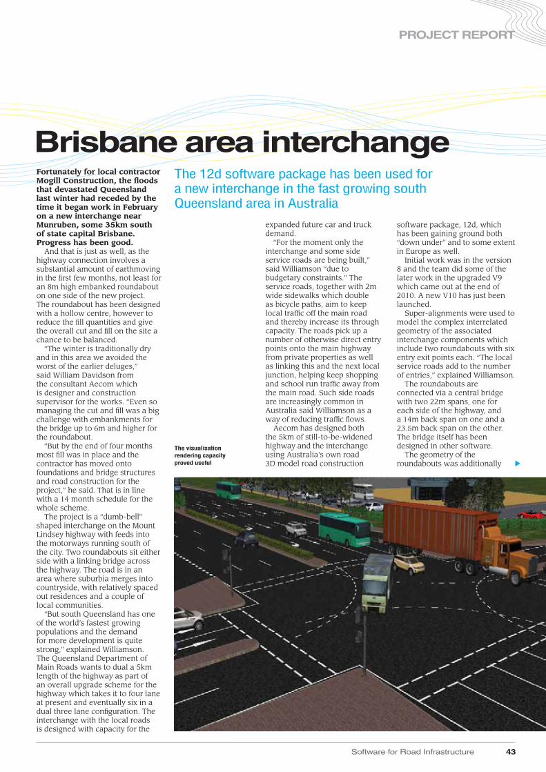
Software for Road Infrastructure 43
PROJECT REPORT
expanded future car and truck demand.
“For the moment only the interchange and some side service roads are being built,” said Williamson “due to budgetary constraints.” The service roads, together with 2m wide sidewalks which double as bicycle paths, aim to keep local traffic off the main road and thereby increase its through capacity. The roads pick up a number of otherwise direct entry points onto the main highway from private properties as well as linking this and the next local junction, helping keep shopping and school run traffic away from the main road. Such side roads are increasingly common in Australia said Williamson as a way of reducing traffic flows.
Aecom has designed both the 5km of still-to-be-widened highway and the interchange using Australia’s own road 3D model road construction
software package, 12d, which has been gaining ground both “down under” and to some extent in Europe as well.
Initial work was in the version 8 and the team did some of the later work in the upgraded V9 which came out at the end of 2010. A new V10 has just been launched.
Super-alignments were used to model the complex interrelated geometry of the associated interchange components which include two roundabouts with six entry exit points each. “The local service roads add to the number of entries,” explained Williamson.
The roundabouts are connected via a central bridge with two 22m spans, one for each side of the highway, and a 14m back span on one and a 23.5m back span on the other. The bridge itself has been designed in other software.
The geometry of the roundabouts was additionally
Fortunately for local contractor Mogill Construction, the floods that devastated Queensland last winter had receded by the time it began work in February on a new interchange near Munruben, some 35km south of state capital Brisbane. Progress has been good.
And that is just as well, as the highway connection involves a substantial amount of earthmoving in the first few months, not least for an 8m high embanked roundabout on one side of the new project. The roundabout has been designed with a hollow centre, however to reduce the fill quantities and give the overall cut and fill on the site a chance to be balanced.
“The winter is traditionally dry and in this area we avoided the worst of the earlier deluges,” said William Davidson from the consultant Aecom which is designer and construction supervisor for the works. “Even so managing the cut and fill was a big challenge with embankments for the bridge up to 6m and higher for the roundabout.
“But by the end of four months most fill was in place and the contractor has moved onto foundations and bridge structures and road construction for the project,” he said. That is in line with a 14 month schedule for the whole scheme.
The project is a “dumb-bell” shaped interchange on the Mount Lindsey highway with feeds into the motorways running south of the city. Two roundabouts sit either side with a linking bridge across the highway. The road is in an area where suburbia merges into countryside, with relatively spaced out residences and a couple of local communities.
“But south Queensland has one of the world’s fastest growing populations and the demand for more development is quite strong,” explained Williamson. The Queensland Department of Main Roads wants to dual a 5km length of the highway as part of an overall upgrade scheme for the highway which takes it to four lane at present and eventually six in a dual three lane configuration. The interchange with the local roads is designed with capacity for the
Brisbane area interchangeThe 12d software package has been used for a new interchange in the fast growing south Queensland area in Australia
The visualisation rendering capacity proved useful
▲

complicated by the height on one side of 8m. The decision to reduce fill with a hollow centre added complexity. The team took advantage of this central circular tapered void however by installing a water run-off treatment facility with settling areas. The water does not build up however into a pond and he said, “There is an outlet.”
This and other drainage was done using a separate module in the 12d package which is built up from a base module for digital terrain modelling, with a road alignment and elevation module, a cut and fill earthwork calculation module and others.
In the road module, chains were used to control all design processes including the export of drawing data used in generating more than 500 drawings which document the project. The road and alignment capacities allowed the use of speed tables on the primary control alignments which simplified the application of super-elevation and provided the basis of the road surface which was then modified as required by the designer. The drainage design module allowed direct integration via model and tin sharing to ensure the drainage designers were always working with the most up to date road design data says Williamson.
The 12d package includes a visualisation rendering capacity and this proved useful said Williamson, “It’s not as realistic as some complex packages but it is good enough and very quick to prepare a rendered view,” he commented. “That is highly useful for explaining things to the client, or for setting up an eyeline view to show someone how things will look from their property for example.”
He said that a useful visual can be created in just 20 minutes or so.
With 25m deep piled bridge foundations now complete the project is beginning to take shape. Work continues until the (Australian) autumn next year. ■
12dwww.12d.com
44 Software for Road Infrastructure
PROJECT REPORT
“In the road module chains were used to control all design processes including the export of drawing data used in generating more than 500 drawings which document the project
”
Site conditions at the project did prove challenging
The project called for the construction of a complex interchange
Using the software allowed the project team to analyse an array of factors during the design phase
▲

StreetMapper is a joint development between UK based 3D Laser Mapping and German based guidance and navigation specialist IGI and offers vehicle-mounted laser scans with a 360° field of view. The company claims a range of 300m and a capacity of 300,000 measurements per
second per sensor. Depending on the set-up used, accuracies can be as good as 10mm. ■
3D Laser Mappingwww.3dlasermapping.com
Allpoint Systemswww.allpointsystems.com
StreetMapper Bridges uses software from American firm Allpoint Systems which can process entire directories of 3D laser scanned data. The complex algorithms in the Allpoint Perception Engine can simplify aspects of the hundreds of millions or even billions of points contained in scans and extract usable data for specific purposes.
The software, which has already found applications in tunnel and underground spaces, has a hybrid of software tools that mix automation for time consuming repetitive tasks with user interaction to make more complex decisions. StreetMapper is a vehicle-based laser mapping system which uses GPS and inertial systems to give a positional reference to data picked up during a mobile laser scan, rapidly and quickly providing a huge number of measurements along roads.
But handling laser cloud data is still difficult. By providing the tools for automatic calculation of bridge heights and other measurements the new service simplifies the processing of the billions of individual laser scanned measurements recorded. It is well suited for tasks like road construction and maintenance and abnormal route calculations. The new application extracts cross sections from the data and calculates clearances and other user defined measurements. This automation enables large-scale use of laser mapping by eliminating manual inefficiencies.
StreetMapper is offering the processing as a service (Software as a Service) for which customers buy an annual licence and data storage, or as an on project basis. In that case the company’s developers take on the data processing to agreed deliverables. “This is a great addition and a must for anyone in road surveying,” said Michael Frecks, president of Terrametrix, a professional survey company which is using the system. “It eliminates time consuming and repetitive tasks.”
Laser surveys calculate bridges
Software for Road Infrastructure 45
LASER SCANNING & POINT CLOUDS
An exciting development in the use of laser scan point clouds is shown in the latest service from British survey company StreetMapper which offers automatic measurement of bridge heights, measurement of road surfaces and identification of lane markings
Faster and more efficient analysis of bridge dimensions can be achieved by using the latest technology, speeding construction processes

Software for Road Infrastructure 46
CLOUD COMPUTING
real time system monitoring by Mayrise which is able to anticipate potential problems and can use server support from one of the UK’s biggest Internet hosting companies. “Another advantage will be the reduction of office time entering information from paper field reports,” said Elliot who commented that there is a continual backlog. That will be addressed using wireless data services for remote working; highways inspectors, engineers, surveyors and other mobile workers will be using smart phones or PDA’s allowing a productivity gain and better service.
The web hosted service will include access to digital street maps and overlays such as the council’s terrier and overlays showing street light locations, defects, faults, and highways
assets. Potentially any mapped highways related data can be added he explained. Mayrise has mobile applications for highways maintenance, street lighting and street works such as mobile MapNow for locating assets, faults or defects in the field. They use forms designed for real time updates and improvements in the mapped overlays can then be exported to a Geographic Information System. Elliot believes the web managed will make automation possible for other functions too, which would not have been cost effective previously. “The street café culture in this seaside town suggests trader placement and highway enforcement would be obvious extensions,” he said. ■
Mayrise Systemswww.mayrise.co.uk
Brighton & Hove City Council has become one of the first local authorities in Britain to operate its highways management system with an Internet hosted service.
For the moment the street works function alone will benefit from the service which is being offered by system provider Mayrise Systems. But other functions such as street lighting and highways will follow. The changeover from the user point of view will be seamless as they will simply access the same functions as before but with secure access online.
The decision to move the Street Works system externally was two-fold says council highways services IT manager Jeff Elliot. Firstly, the council needed to meet new government requirements and secondly, the existing system needed updating. The latest statutory obligations under the UK’s Traffic Management Act require frequent interchange of data between external organisations and the council to keep the council informed of works and to monitor and enforce controls. But this conflicts with an increasingly important need for data security.
Hosted services option offered an ideal solution he said, “Restrictions and firewalls around the council’s data are becoming more secure and effective.” Elliot continued, “But it can make internally hosted systems more complex.”
By externalising street works it is possible to communicate directly with utility companies, contractors and others as needed under the TMA. Mayrise Systems and the council devised a secure, resilient solution that encrypts data transfers from within the council to the remote system. Authorised external users will also be able to gain access from different locations anytime they need to. “Software systems and data are managed externally by Mayrise Systems and that reduces the burden on the council IT department,” said Elliot.
Highways will also benefit from
Cloud computing for Brighton
The development of cloud computing – hosted services on the Internet – is becoming more commonplace for local authorities in the UK
Using the Mayrise package is allowing the authorities in Brighton to improve road repair efficiency and reduce costs

BarriersDelays to better
barrier safety for
Europe’s powered two
wheeler riders. p41
SoftwareInnovative GIS and
software solutions are
coming to market
from the three key
market players. p37
EarthmovingManufacturers are rolling
out sophisticated
machines for the European,
North American and
Japanese markets. p31
Effi cient bridge
constructionHarsco rises to tall order p51
NOVEMBER/DECEMBER 2011www.worldhighways.com
INTERNATIONAL ROAD FEDERATION
O F F I C I A L
J O U R N A L
EUROFILEEDITION
CO
N/A
GG
2011
ww
w.w
orldhighways.com
ww
w.A
ggBusiness.com
AP
RIL 2011
FREE SUBSCRIPTION
FREE subscription to World Highways
www.worldhighways.com
● 12 months supply of World Highways magazine (9 issues per year) in print● The World Highways eNewsletter – emailed twice a month to over 50,000 qualified individuals ● Unlimited access to the World Highways website – with over 8 years of archived industry
information in a fully searchable format● Specials and supplements that focus on specific areas
A subscription to World Highways gives you:
Register for FREE online @ www.roplreg.com
Guarantee your copies of World Highways by registering today @ www.roplreg.com
Route One Publishing Ltd. Horizon House, Azalea Drive, Swanley, Kent, BR8 8JR. UK. Tel: +44 1322 612055 Fax: +44 161 603 0891Informed Authority