Embed Size (px)
Citation preview


SOLID MATERIAL SPECIFIC GRAVITY
Aluminium 2,70Laminated Aluminium 2,55 - 2,80Antimony 6,68Asbestos 2,10 - 2,80Arsenic (Crystalline) 5,72Barium 3,59Barytes 4,50Basalt 2,72 - 3,20Beryllium 1,82Bismuth 9,80Brick - Common 1,40 - 2,30Brass - Cast 8,40Brass - Laminated 8,50Cadmium 8,65Calcium 1,55Carbon (Diamond) 3,51Cement - Portland 3,10 - 3,20Chalk 1,80 - 2,80Charcoal 0,30 - 0,60Chromium 7,10Chromium oxyde 5,21Clay 1,28 - 2,60Coal - Bitum - Broken 1,20 - 1,50Coal - Anthr - Broken 1,40 - 1,80Cobalt 8,90Coke - Loose 1,00 - 1,40Concrete Masonry 2,20 - 2,40(Cement, Stone, Sand,...)
Copper - Pure 8,92Copper - Laminated 8,80 - 8,95Copper - Cast 8,80 - 8,95Corundum 3,90 - 4,00Diamond 3,51Dolomite 2,90Earth - Dry - Loose 1,20Earth - Moist - Loose 1,30Feldspar 2,50 - 2,70
Flint 3,20 - 4,70Glass 2,40 - 2,80Gold 19,29Granite 2,60 - 2,70Graphite 2,26Grease 0,93Gypsum 2,28 - 2,80Hornblende 3,00Ice 0,88 - 0,92Iridium 22,40Iron - Raw 7,0 - 7,80Iron - Pure 7,86Iron - Wrought 7,60 - 7,90Iron - Cast 7,40 - 7,80Iron - Oxyde 5,10Lead 11,33Lime 0,85 - 1,0Limestone - Solid 2,10 - 2,95Lithium 0,53Magnesia 3,04Magnesium 1,74Manganese 7,20Marble 2,30 - 2,70Mica 2,80 - 2,93Molybdenum 10,20Mud - River 1,44 - 1,84Nickel 8,90Palladium 12,00Paper 0,75 - 1,15Paraffin 0,87 - 0,91Platinum 21,45Pitch 1,07 - 1,25Potassium 0,86Quartz 2,50 - 2,80Radium 5,00Rhodium 12,50Rubber 0,92 - 0,96
Sand - Dry 1,40 - 1,70Sand - Wet 1,89 - 2,16Sandstone 1,90 - 2,50Schist - Slate 2,60 - 2,90Selenium 4,26 - 4,80Silicon - Amorphous 2,00Silver 10,50Sodium 0,97Soil 1,12Soapstone 2,60 - 2,80Snow 0,12Snow - Compact 0,80Sulphur -
Amorphous -Monoclinic -Rhombic 1,93 - 2,07
Steel - Cast 7,80Talc 2,60 - 2,80Tallow 0,90 - 1,00Tar 1,00 - 1,20Thorium 11,20Tungsten 19,30Uranium 11,28Tin - Cast 7,20 - 7,50Tin - Laminated 7,20 - 7,50Vanadium 5,96Zinc 7,14Zinc - Cast 6,86Zinc - Laminated 7,15Wood - Oak 0,60 - 0,90Wood - Birch - Tree 0,71 - 0,72Wood - Alden 0,55Wood - Charm 0,72Wood - Maple - Tree 0,75Wood - Pine - Tree 0,43 - 0,67Wood - Larch - Tree 0,75
MATERIAL SPECIFIC GRAVITY(kg/dm3) MATERIAL SPECIFIC GRAVITY
(kg/dm3) MATERIAL SPECIFIC GRAVITY(kg/dm3)
© Magotteaux 10.02
The information and data are accurate to the best of our knowledge and belief,but are intended for general information only. Applications suggested for thematerials are described only to help readers make their own evaluations and areneither guarantees nor to be construed as express or implied warranties of suit-ability for these or other applications.
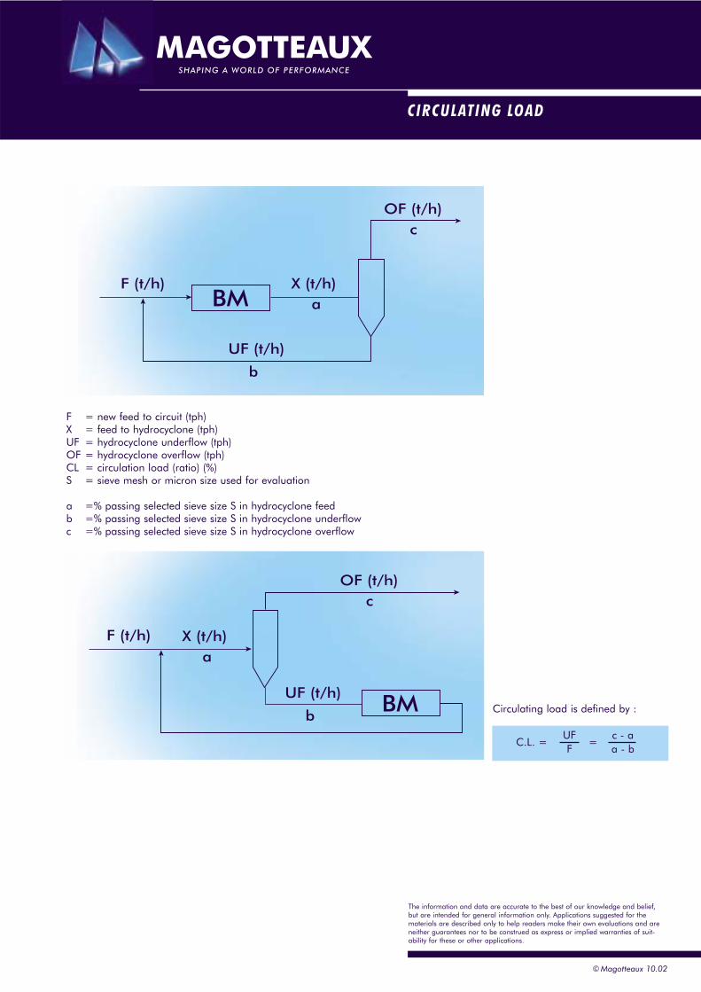
CIRCULATING LOAD
© Magotteaux 10.02
F = new feed to circuit (tph)X = feed to hydrocyclone (tph)UF = hydrocyclone underflow (tph)OF = hydrocyclone overflow (tph)CL = circulation load (ratio) (%)S = sieve mesh or micron size used for evaluation
a =% passing selected sieve size S in hydrocyclone feedb =% passing selected sieve size S in hydrocyclone underflowc =% passing selected sieve size S in hydrocyclone overflow
Circulating load is defined by :
C.L. =UF c - aF a - b
=
F (t/h) X (t/h)
UF (t/h)
OF (t/h)
a
b
c
BM
F (t/h) X (t/h)
UF (t/h)
OF (t/h)
a
b
c
BM
The information and data are accurate to the best of our knowledge and belief,but are intended for general information only. Applications suggested for thematerials are described only to help readers make their own evaluations and areneither guarantees nor to be construed as express or implied warranties of suit-ability for these or other applications.

SIEVE
© Magotteaux 10.02
Mesh Microns
3,5 5.6004 4.7505 4.0006 3.3507 2.8008 2.360
12 1.700
16 1.18018 1.00020 85025 710
35 500
45 35550 30060 25070 212
100 150
140 106170 90200 75230 63270 53
325 45
400 38500 25
Microns2,5 8.000
3,5 5.600
5 4.000
7 2.800
9 2.000
12 1.400
18 1.000
25 710
35 500
45 355
60 25070 21280 180
120 125140 106170 90200 75230 63270 53
325 45
400 38
Microns
3 5.600
4 4.0005 3.3506 2.800
8 2.000
10 1.700
14 1.18016 1.00018 850
25 60030 500
36 42544 355
60 25072 212
100 150
150 106170 90200 75240 63
300 53
350 45
400 38
SIEVE
TYLER BRITISH STANDARDUSA - A.S.T.M.E. 11.70
The information and data are accurate to the best of our knowledge and belief,but are intended for general information only. Applications suggested for thematerials are described only to help readers make their own evaluations and areneither guarantees nor to be construed as express or implied warranties of suit-ability for these or other applications.
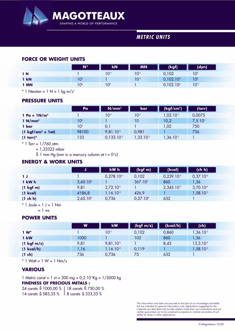
METRIC UNITS
FORCE OR WEIGHT UNITS
* 1 Newton = 1 N = 1 kg m/s2
1 N 1 10-3 10-6 0,102 105
1 kN 103 1 10-3 0,102.103 108
1 MN 106 103 1 0,102.106 1011
(dyn)(kgf)MNkNN*
PRESSURE UNITS
* 1 Torr = 1/760 atm= 1,33322 mbar
1 mm Hg (mm in a mercury column at t = 0°c)
1 Pa = 1N/m2 1 10-6 10-5 1,02.10-5 0,00751 N/mm2 106 1 10 10,2 7,5.103
1 bar 105 0,1 1 1,02 750(1 kgf/am2 = 1at) 98100 9,81.10-2 0,981 1 736(1 torr)* 133 0,133.10-3 1,33.10-3 1,36.10-3 1
(torr)(kgf/cm2)barN/mm2Pa
=>
ENERGY & WORK UNITS
* 1 Joule = 1 J = 1 Nm= 1 ws
1 J 1 0,278.10-6 0,102 0,239.10-3 0,37.10-6
1 kW h 3,60.106 1 367.103 860 1,36(1 kgf m) 9,81 2,72.10-6 1 2,345.10-3 3,70.10-6
(1 kcal) 4186,8 1,16.10-3 426,9 1 1,58.10-3
(1 ch h) 2,65.106 0,736 0,27.106 632 1
(ch h)(kcal)(kgf m)kW hJ
POWER UNITS
1 W* 1 10-3 0,102 0,860 1,36.10-3
1 kW 1000 1 102 860 1,36(1 kgf m/s) 9,81 9,81.10-3 1 8,43 13,3.10-3
(1 kcal/h) 1,16 1,16.10-3 0,119 1 1,58.10-3
(1 ch) 736 0,736 75 632 1
(ch)(kcal/h)(kgf m/s)kWW
* 1 Watt = 1 W = 1 Nm/s
VARIOUS
1 Metric carat = 1 ct = 200 mg = 0,2.10-3Kg = 1/5000 kgFINENESS OF PRECIOUS METALS :24 carats 1000,00 % 18 carats 750,00 %14 carats 583,33 % 8 carats 333,33 %
=>
=>
=>
=>
© Magotteaux 10.02
The information and data are accurate to the best of our knowledge and belief,but are intended for general information only. Applications suggested for thematerials are described only to help readers make their own evaluations and areneither guarantees nor to be construed as express or implied warranties of suit-ability for these or other applications.
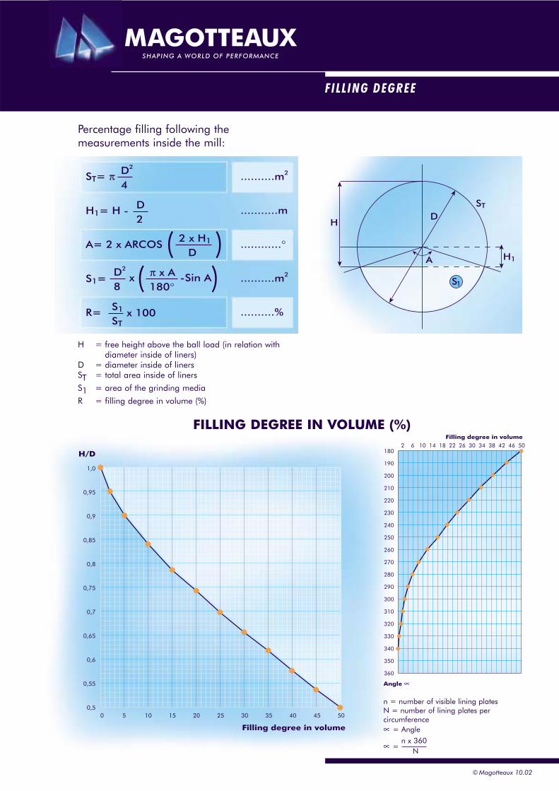
FILLING DEGREE
Percentage filling following the measurements inside the mill:
H = free height above the ball load (in relation withdiameter inside of liners)
D = diameter inside of linersST = total area inside of liners
S1 = area of the grinding media
R = filling degree in volume (%)
HD
A
ST
S1
H1
00,5
0,55
0,6
0,65
0,7
0,75
0,8
0,85
0,9
0,95
1,0
H/D
5 10 15 20 25 30 35 40 45 50
Filling degree in volume
360
350
340
330
320
310
300
290
280
270
260
250
240
230
220
210
200
190
1802 6 10 14 18 22 26 30 34 38 42 46 50
Angle ∝
Filling degree in volume
ST= π ..........m2
...........m
............°
..........m2
..........%
D2
4
R= S1
ST
D2
8
2 x H1
D
H1= H - D2
A= 2 x ARCOS ( )π x A180°
S1= ( )x
x 100
-Sin A
FILLING DEGREE IN VOLUME (%)
n = number of visible lining platesN = number of lining plates per circumference∝ = Angle
∝ =n x 360
N
© Magotteaux 10.02
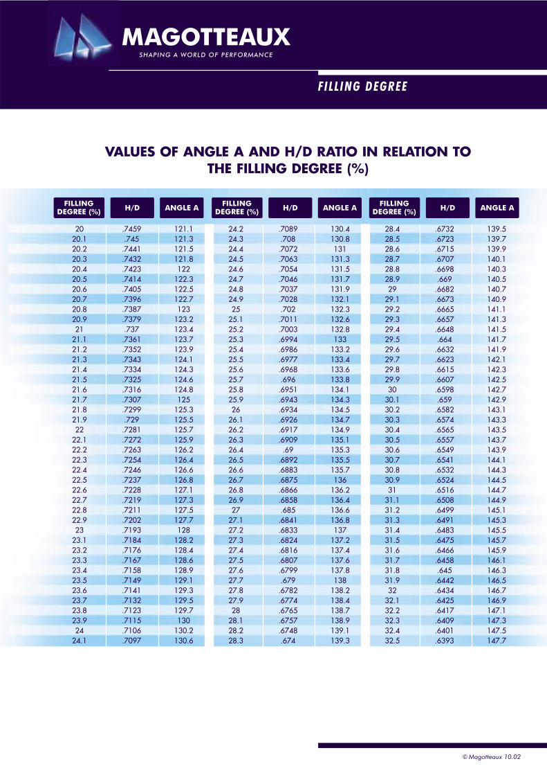
FILLING DEGREE
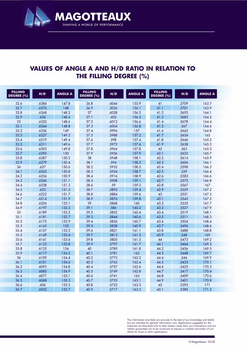
VALUES OF ANGLE A AND H/D RATIO IN RELATION TO THE FILLING DEGREE (%)
20 .7459 121.120.1 .745 121.320.2 .7441 121.520.3 .7432 121.820.4 .7423 12220.5 .7414 122.320.6 .7405 122.520.7 .7396 122.720.8 .7387 12320.9 .7379 123.221 .737 123.4
21.1 .7361 123.721.2 .7352 123.921.3 .7343 124.121.4 .7334 124.321.5 .7325 124.621.6 .7316 124.821.7 .7307 12521.8 .7299 125.321.9 .729 125.522 .7281 125.7
22.1 .7272 125.922.2 .7263 126.222.3 .7254 126.422.4 .7246 126.622.5 .7237 126.822.6 .7228 127.122.7 .7219 127.322.8 .7211 127.522.9 .7202 127.723 .7193 128
23.1 .7184 128.223.2 .7176 128.423.3 .7167 128.623.4 .7158 128.923.5 .7149 129.123.6 .7141 129.323.7 .7132 129.523.8 .7123 129.723.9 .7115 13024 .7106 130.2
24.1 .7097 130.6
24.2 .7089 130.424.3 .708 130.824.4 .7072 13124.5 .7063 131.324.6 .7054 131.524.7 .7046 131.724.8 .7037 131.924.9 .7028 132.125 .702 132.3
25.1 .7011 132.625.2 .7003 132.825.3 .6994 13325.4 .6986 133.225.5 .6977 133.425.6 .6968 133.625.7 .696 133.825.8 .6951 134.125.9 .6943 134.326 .6934 134.5
26.1 .6926 134.726.2 .6917 134.926.3 .6909 135.126.4 .69 135.326.5 .6892 135.526.6 .6883 135.726.7 .6875 13626.8 .6866 136.226.9 .6858 136.427 .685 136.6
27.1 .6841 136.827.2 .6833 13727.3 .6824 137.227.4 .6816 137.427.5 .6807 137.627.6 .6799 137.827.7 .679 13827.8 .6782 138.227.9 .6774 138.428 .6765 138.7
28.1 .6757 138.928.2 .6748 139.128.3 .674 139.3
28.4 .6732 139.528.5 .6723 139.728.6 .6715 139.928.7 .6707 140.128.8 .6698 140.328.9 .669 140.529 .6682 140.7
29.1 .6673 140.929.2 .6665 141.129.3 .6657 141.329.4 .6648 141.529.5 .664 141.729.6 .6632 141.929.7 .6623 142.129.8 .6615 142.329.9 .6607 142.530 .6598 142.7
30.1 .659 142.930.2 .6582 143.130.3 .6574 143.330.4 .6565 143.530.5 .6557 143.730.6 .6549 143.930.7 .6541 144.130.8 .6532 144.330.9 .6524 144.531 .6516 144.7
31.1 .6508 144.931.2 .6499 145.131.3 .6491 145.331.4 .6483 145.531.5 .6475 145.731.6 .6466 145.931.7 .6458 146.131.8 .645 146.331.9 .6442 146.532 .6434 146.7
32.1 .6425 146.932.2 .6417 147.132.3 .6409 147.332.4 .6401 147.532.5 .6393 147.7
FILLINGDEGREE (%) ANGLE AH/D FILLING
DEGREE (%) ANGLE AH/D FILLINGDEGREE (%) ANGLE AH/D
© Magotteaux 10.02
© Magotteaux 10.02
36.8 .6044 155.936.9 .3036 156.137 .6028 156.3
37.1 .602 156.537.2 .6012 156.637.3 .6004 156.837.4 .5996 15737.5 .5988 157.237.6 .598 157.437.7 .5972 157.637.8 .5964 157.837.9 .5956 157.938 .5948 158.1
38.1 .594 158.338.2 .5932 158.538.3 .5924 158.738.4 .5916 158.938.5 .5908 159.138.6 .59 159.338.7 .5892 159.438.8 .5884 159.638.9 .5876 159.839 .5868 160
39.1 .586 160.239.2 .5852 160.439.3 .5844 160.639.4 .5836 160.739.5 .5828 160.939.6 .5821 161.139.7 .5813 161.339.8 .5805 161.539.9 .5797 161.740 .5789 161.8
40.1 .5781 16240.2 .5773 162.240.3 .5765 162.440.4 .5757 162.640.5 .5749 162.840.6 .5741 16340.7 .5733 163.140.8 .5725 163.340.9 .5717 163.5
41 .5709 163.741.1 .5701 163.941.2 .5693 164.141.3 .5685 164.241.4 .5678 164.441.5 .567 164.641.6 .5662 164.841.7 .5654 16541.8 .5646 165.241.9 .5638 165.342 .563 165.5
42.1 .5622 165.742.2 .5614 165.942.3 .5606 166.142.4 .5598 166.342.5 .559 166.442.6 .5583 166.642.7 .5575 166.842.8 .5567 16742.9 .5559 167.243 .5551 167.3
43.1 .5543 167.543.2 .5535 167.743.3 .5527 167.943.4 .5519 168.143.5 .5511 168.343.6 .5504 168.443.7 .5496 168.643.8 .5488 168.843.9 .548 16944 .5472 169.2
44.1 .5464 169.344.2 .5456 169.544.3 .5448 169.744.4 .544 169.944.5 .5433 170.144.6 .5425 170.344.7 .5417 170.444.8 .5409 170.644.9 .5401 170.845 .5393 171
45.1 .5385 171.2
32.6 .6384 147.832.7 .6376 14832.8 .6368 148.232.9 .636 148.433 .6352 148.6
33.1 .6344 148.833.2 .6336 14933.3 .6327 149.233.4 .6319 149.433.5 .6311 149.633.6 .6303 149.833.7 .6295 15033.8 .6287 150.233.9 .6279 150.434 .627 150.6
34.1 .6262 150.834.2 .6254 150.934.3 .6246 151.134.4 .6238 151.334.5 .623 151.534.6 .6222 151.734.7 .6214 151.934.8 .6206 152.134.9 .6197 152.335 .6189 152.5
35.1 .6181 152.735.2 .6173 152.935.3 .6165 15335.4 .6157 153.235.5 .6149 153.435.6 .6141 153.635.7 .6133 153.835.8 .6125 15435.9 .6117 154.236 .6109 154.4
36.1 .6101 154.636.2 .6093 154.836.3 .6085 154.936.4 .6077 155.136.5 .6068 155.336.6 .606 155.536.7 .6052 155.7
VALUES OF ANGLE A AND H/D RATIO IN RELATION TO THE FILLING DEGREE (%)
FILLINGDEGREE (%) ANGLE AH/D FILLING
DEGREE (%) ANGLE AH/D FILLINGDEGREE (%) ANGLE AH/D
The information and data are accurate to the best of our knowledge and belief,but are intended for general information only. Applications suggested for thematerials are described only to help readers make their own evaluations and areneither guarantees nor to be construed as express or implied warranties of suit-ability for these or other applications.
HB HRcHB HRc HB HRc HB HRc HB HRc
HARDNESS & IMPACT ENERGY
164 8.20169 9.10174 10.00179 11.00184 11.90189 12.80194 13.60199 14.50204 15.40209 16.20214 17.10219 17.90224 18.70229 19.50234 20.40239 21.20244 22.00249 22.70254 23.50259 24.30264 25.00269 25.70274 26.50279 27.20284 27.90289 28.60294 29.30299 30.00304 30.70309 31.30314 32.00319 32.50324 33.30329 33.90334 34.50339 35.10344 35.70349 36.30354 36.90359 37.40364 38.00369 38.50374 39.10379 39.60384 40.10389 40.60394 41.10399 41.60404 42.10409 42.60414 43.00419 43.50424 43.90429 44.40434 44.80439 45.20444 45.60449 46.00
163 8.00168 8.90173 9.90178 10.80183 11.70188 12.60193 13.50198 14.30203 15.20208 16.10213 16.90218 17.80223 18.60228 19.40233 20.20238 21.00243 21.80248 22.50253 23.30258 24.10263 24.90268 25.60273 26.30278 27.10283 27.80288 28.50293 29.20298 29.90303 30.50308 31.20313 31.80318 32.50323 33.10328 33.80333 34.40338 35.00343 35.60348 36.20353 36.70358 37.30363 37.90368 38.40373 39.00378 39.50383 40.00388 40.50393 41.00398 41.50403 42.00408 42.50413 42.90418 43.40423 43.80428 44.30433 44.70438 45.10443 45.50448 45.90
162 7.80167 8.70172 9.70177 10.60182 11.50187 12.40192 13.30197 14.20202 15.00207 15.90212 16.70217 17.60222 18.40227 19.20232 20.00237 20.80242 21.60247 22.40252 23.20257 24.00262 24.70267 25.50272 26.20277 26.90282 27.60287 28.30292 29.00297 29.70302 30.40307 31.10312 31.70317 32.40322 33.00327 33.60332 34.20337 34.90342 35.50347 36.00352 36.60357 37.20362 37.80367 38.30372 38.90377 39.40382 39.90387 40.40392 40.90397 41.40402 41.90407 42.40412 42.80417 43.30422 43.70427 44.20432 44.60437 45.00442 45.40447 45.80
161 7.60166 8.60171 9.50176 10.40181 11.30186 12.20191 13.10196 14.00201 14.90206 15.70211 16.60216 17.40221 18.20226 19.10231 19.90236 20.70241 21.50246 22.30251 23.00256 23.80261 24.50266 25.30271 26.00276 26.80281 27.50286 28.20291 28.90296 29.60301 30.30306 30.90311 31.60316 32.20321 32.90326 33.50331 34.10336 34.70341 35.30346 35.90351 36.50356 37.10361 37.60366 38.20371 38.70376 39.30381 39.80386 40.30391 40.80396 41.30401 41.80406 42.30411 42.70416 43.20421 43.70426 44.10431 44.50436 44.90441 45.30446 45.70
160 7.40165 8.40170 9.30175 10.20180 11.10185 12.00190 12.90195 13.80200 14.70205 15.60210 16.40215 17.20220 18.10225 18.90230 19.70235 20.50240 21.30245 22.10250 22.90255 23.70260 24.40265 25.20270 25.90275 26.60280 27.30285 28.10290 28.80295 29.40300 30.10305 30.80310 31.50315 32.10320 32.70325 33.40330 34.00335 34.60340 35.20345 35.80350 36.40355 37.00360 37.50365 38.10370 38.60375 39.20380 39.70385 40.20390 40.70395 41.20400 41.70405 42.20410 42.70415 43.10420 43.60425 44.00430 44.40435 44.90440 45.30445 45.70450 46.10
720 64.60725 65.00730 -735 -740 65.70745 -750 -755 66.40760 -765 -770 67.00
650 -655 61.00660 -665 -670 62.00675 -680 62.50685 -690 63.00695 -700 -705 63.80710 -
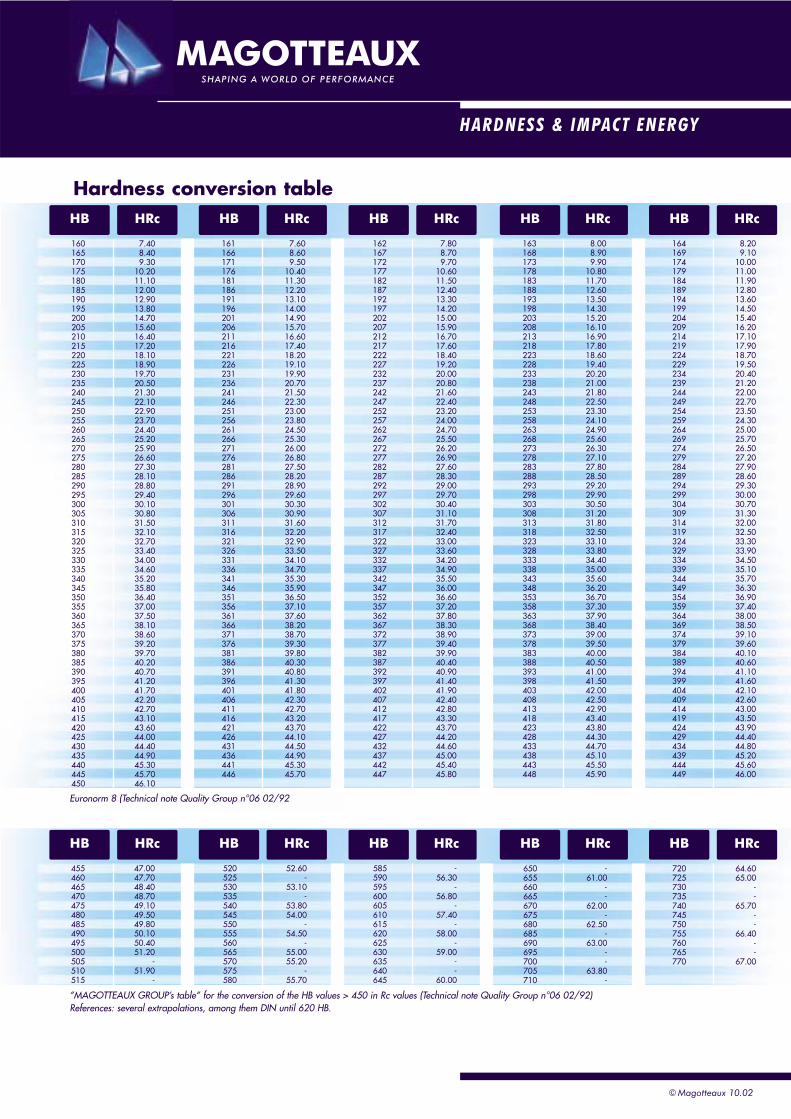
Euronorm 8 (Technical note Quality Group n°06 02/92
585 -590 56.30595 -600 56.80605 -610 57.40615 -620 58.00625 -630 59.00635 -640 -645 60.00
520 52.60525 -530 53.10535 -540 53.80545 54.00550 -555 54.50560 -565 55.00570 55.20575 -580 55.70
455 47.00460 47.70465 48.40470 48.70475 49.10480 49.50485 49.80490 50.10495 50.40500 51.20505 -510 51.90515 -
HB HRcHB HRc HB HRc HB HRc HB HRc
Hardness conversion table
”MAGOTTEAUX GROUP’s table” for the conversion of the HB values > 450 in Rc values (Technical note Quality Group n°06 02/92)References: several extrapolations, among them DIN until 620 HB.
© Magotteaux 10.02
© Magotteaux 10.02
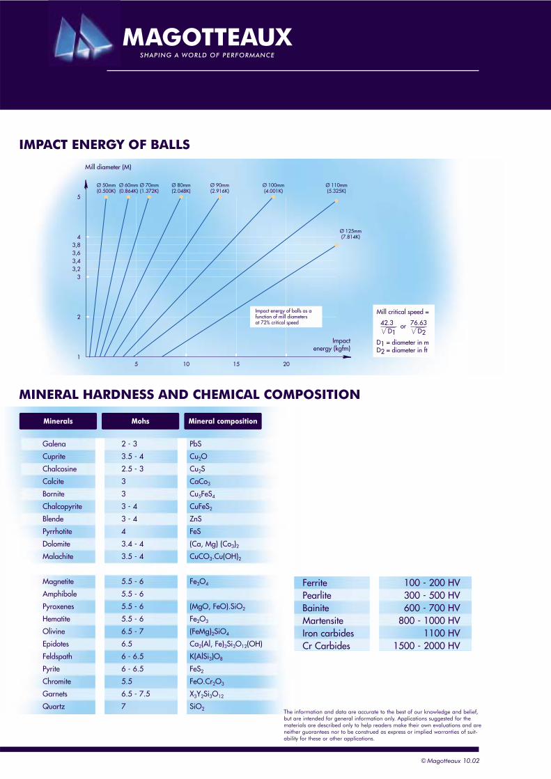
IMPACT ENERGY OF BALLS
MINERAL HARDNESS AND CHEMICAL COMPOSITION
Galena 2 - 3 PbS
Cuprite 3.5 - 4 Cu2O
Chalcosine 2.5 - 3 Cu2S
Calcite 3 CaCo3
Bornite 3 Cu5FeS4
Chalcopyrite 3 - 4 CuFeS2
Blende 3 - 4 ZnS
Pyrrhotite 4 FeS
Dolomite 3.4 - 4 (Ca, Mg) (Co3)2Malachite 3.5 - 4 CuCO3.Cu(OH)2
Magnetite 5.5 - 6 Fe3O4
Amphibole 5.5 - 6
Pyroxenes 5.5 - 6 (MgO, FeO).SiO2
Hematite 5.5 - 6 Fe2O3
Olivine 6.5 - 7 (FeMg)2SiO4
Epidotes 6.5 Ca2(Al, Fe)3Si3O12(OH)
Feldspath 6 - 6.5 K(AlSi3)O8
Pyrite 6 - 6.5 FeS2
Chromite 5.5 FeO.Cr2O3
Garnets 6.5 - 7.5 X3Y2Si3O12
Quartz 7 SiO2
Ferrite 100 - 200 HVPearlite 300 - 500 HVBainite 600 - 700 HVMartensite 800 - 1000 HVIron carbides 1100 HVCr Carbides 1500 - 2000 HV
51
2
33,23,43,63,8
4
5
10 15 20
Ø 50mm(0.500K)
Ø 60mm(0.864K)
Ø 70mm(1.372K)
Ø 80mm(2.048K)
Ø 90mm(2.916K)
Ø 100mm(4.001K)
Ø 110mm(5.325K)
Ø 125mm(7.814K)
Impact energy of balls as afunction of mill diametersat 72% critical speed
Mill diameter (M)
Impactenergy (kgfm)
Mill critical speed =
D1 = diameter in mD2 = diameter in ft
42.3D1
or 76.63D2
Mineral compositionMohsMinerals
The information and data are accurate to the best of our knowledge and belief,but are intended for general information only. Applications suggested for thematerials are described only to help readers make their own evaluations and areneither guarantees nor to be construed as express or implied warranties of suit-ability for these or other applications.

UNITS CONVERSION
HANDY MULTIPLIERS
Acres 43,560 Square feetAcres 4047 Square metersAcres 1.562x10⁻³ Square milesAtmospheres 76.0 Cms. of mercuryAtmospheres 29.92 Inches of mercuryAtmospheres 33.90 Feet of waterAtmospheres 10,333 Kgs./sq. meterAtmospheres 14.70 Lbs./sq. InchAtmospheres 1.058 Tons/sq. ft.British Thermal Units 0.2520 Kilogram-caloriesBritish Thermal Units 3.927x10⁻⁴ Horsepower-hrsBritish Thermal Units 107.5 Kilogram-metersBritish Thermal Units 2.928x10⁻⁴ Kilowatt-hrsB.T.U. 1.055056 KilojouleB.T.U./min 0.02356 HorsepowerB.T.U./min 0.01757 KilowattsB.T.U./min 17.57 WattsCentares (Centiares) 1 Square metersCentigrams 0.01 GramsCentiliters 0.01 LitersCentimeters 0.3937 InchesCentimeters 0.1 MetersCentimeters 10 MilimetersCentimeters of mercury 0.01316 AtmospheresCentimeters of mercury 0.4461 Feet of waterCentimeters of mercury 136.0 Kgs./sq. meterCentimeters of mercury 27.85 Lbs./sq. ft.Centimeters of mercury 0.1934 Lbs./sq. inchCentimeters/sec. 1.969 Feet/min.Centimeters/sec. 0.03281 Feet/sec.Centimeters/sec. 0.036 Kilometers/hr.Centimeters/sec. 0.6 Meters/min.Centimeters/sec. 0.02237 Miles/hr.Centimeters/sec. 3.728x10⁻⁴ Miles/min.Cubic centimeters 3.531x10⁻⁵ Cubic feetCubic centimeters 6.102x10⁻² Cubic inchesCubic centimeters 10-6 Cubic metersCubic centimeters 2.642x10⁻⁴ GallonsCubic centimeters 10-3 LitersCubic feet 2.832x10⁴ Cubic cms.Cubic feet 1728 Cubic inchesCubic feet 0.02832 Cubic metersCubic feet 7.48052 GallonsCubic feet 28.32 LitersCubic feet/min. 472.0 Cubic cms./sec.Cubic feet/min. 0.1247 Gallons/sec.Cubic feet/min. 0.4720 Liters/sec.Cubic feet/sec. 448.831 Gallons/min.Cubic inches 16.39 Cubic centimetersCubic inches 5.787x10⁻⁴ Cubic feetCubic inches 1.639x10⁻⁵ Cubic metersCubic inches 4.329x10⁻³ GallonsCubic inches 1.639x10⁻² LitersCubic meters 106 Cubic centimetersCubic meters 35.31 Cubic feetCubic meters 61.023 Cubic inchesCubic meters 264.2 GallonsCubic meters 103 LitersDecigrams 0.1 GramsDeciliters 0.1 LitersDecimeters 0.1 MetersDegrees (angle) 60 MinutesDegrees (angle) 0.01745 RadiansDegrees (angle) 3600 SecondsDegrees/sec. 0.01745 Radians/sec.Degrees/sec. 0.1667 Revolutions/min.Degrees/sec. 0.002778 Revolutions/sec.Dekagrams 10 GramsDekaliters 10 LitersDekameters 10 Meters
Feet 30.48 CentimetersFeet 12 InchesFeet 0.3048 MetersFeet of water 0.02950 AtmospheresFeet of water 0.8826 Inches of mercuryFeet of water 304.8 Kgs./sq. meterFeet of water 62.43 Lbs./sq. ft.Feet of water 0.4335 Lbs./sq. inchGallons 3785 Cubic centimetersGallons 0.1337 Cubis feetGallons 231 Cubic inchesGallons 3.785x10⁻³ Cubic metersGallons 3.785 LitersGallons-Imperial 1.20095 U.S. GallonsGallons-U.S. 0.83267 Imperial GallonsGrams 980.7 DynesGrams 103 MilligramsGrams 0.03527 OuncesGrams 0.03215 Ounces (troy)Grams 2.205x10⁻³ PoundsGrams/liter 1000 Parts/millionHectares 2.471 AcresHectares 1.076x10⁵ Square feetHectograms 100 GramsHectoliters 100 LitersHectometers 100 MetersHectowatts 100 WattsHorsepower 42.44 B.T.U./min.Horsepower 1.014 Horsepower (metric)Horsepower 10.70 Kg-calories/min.Horsepower 0.7457 KilowattsHorsepower 745.7 WattsHorsepower-hours 2547 B.T.U.Horsepower-hours 641.7 Kilogram-caloriesHorsepower-hours 2.737x10⁵ Kilogram-metersHorsepower-hours 0.7457 Kilowatt-hoursInches 2.540 CentimetersInches of mercury 0.03342 AtmospheresInches of mercury 1.133 Feet of waterInches of water 0.07355 Inches of mercuryInches of water 25.40 Kgs./sq. meterInches of water 5.202 Lbs./sq. footInches of water 0.03613 Lbs./sq. inchKilograms 980.665 DynesKilograms 2.205 Lbs.Kilograms 1.102x10⁻³ Tons (short)Kilograms 103 GramsKilograms-calories 3.968 B.T.U.Kilograms-calories 3086 Foot-poundsKilograms-calories 1.558x10⁻³ Horsepower-hrs.Kilograms-calories 1.162x10⁻³ Kilowatt-hoursKilograms-calories 4.1868 KilojouleKilograms-cal./min. 0.09351 HorsepowerKilograms-cal./min. 0.06972 KilowattsKgs./sq. meter 9.678x10⁻⁵ AtmospheresKgs./sq. meter 3.281x10⁻³ Feet of waterKgs./sq. meter 2.896x10⁻³ Inches of mercuryKiloliters 103 LitersKilometers 105 CentimetersKilometers 3281 FeetKilometers 103 MetersKilometers 0.6214 MilesKilometers 1094 YardsKilometers/hr. 27.78 Cms./sec.Kilometers/hr. 54.68 Feet/min.Kilometers/hr. 0.9113 Feet/sec.Kilometers/hr. 0.6214 Miles/hr.Kilowatts 56.92 B.T.U./min.Kilowatts 1.341 HorsepowerKilowatts 14.34 Kg-calories/min.
By To obtainMultiplyBy To obtainMultiply
© Magotteaux 10.02

Kilowatts 103 WattsKilowatt-hours 3415 B.T.U.Kilowatt-hours 1.341 Horsepower-hrs.Kilowatt-hours 860.5 Kilogram-caloriesKilowatt-hours 3.671x10⁵ Kilogram-metersLiters 103 Cubic centimetersLiters 0.03531 Cubic feetLiters 61.02 Cubic inchesLiters 10-3 Cubic metersLiters 0.2642 GallonsMeters 100 CentimetersMeters 3.281 FeetMeters 39.37 InchesMeters 10-3 KilometersMeters 103 MillimetersMeters 1.094 YardsMeters/min. 1.667 Centimeters/sec.Meters/min. 3.281 Feet/min.Meters/min. 0.05468 Feet/sec.Meters/min. 0.06 Kilometers/hr.Meters/min. 0.03728 Miles/hr.Meters/sec. 196.8 feet/min.Meters/sec. 3.281 Feet/sec.Meters/sec. 3.6 Kilometers/hr.Meters/sec. 0.06 Kilometers/min.Meters/sec. 2.237 Miles/hr.Meters/sec. 0.03728 Miles/min.Microns 10-6 MetersMiles 1.609x10⁵ CentimetersMiles 5280 FeetMiles 1.609 KilometersMiles 1760 YardsMiles/hr. 1.609 Kilometers/hr.Milliers 103 KilogramsMilligrams 10-3 GramsMilliliters 10-3 LitersMillimeters 0.1 CentimetersMillimeters 0.03937 InchesMilligrams/liter 1 Parts/millionMinutes (angle) 2.909x10⁻⁴ RadiansOunces 0.0625 PoundsOunces 28.349527 GramsOunces 0.9115 Ounces (troy)Ounces 2.790x10⁻⁵ Tons (long)Ounces 2.835x10⁻⁵ Tons (metric)Ounces (troy) 0.08333 Pounds (troy)Ounces (troy) 31.103481 GramsParts/millions (by weight) 8.345 Lbs./million gal.Pounds 16 OuncesPounds 0.0005 Tons (short)Pounds 453.5924 GramsPounds 1.21528 Pounds (troy)Pounds 14.5833 Ounces (troy)Pounds (troy) 12 Ounces (troy)Pounds (troy) 373.24177 GramsPounds (troy) 3.6735x10⁻⁴ Tons (long)Pounds (troy) 4.1143x10⁻⁴ Tons (short)Pounds (troy) 3.7324x10⁻⁴ Tons (metric)Quadrants (angle) 90 DegreesQuadrants (angle) 5400 MinutesQuadrants (angle) 1.571 RadiansRadians 57.30 DegreesRadians 3438 MinutesRadians 0.637 QuadrantsRadians/sec. 57.30 Degrees/sec.Radians/sec. 0.1592 Revolutions/sec.Radians/sec. 9.549 Revolutions/min.
Radians/sec./sec. 573.0 Revs./min./min.Radians/sec./sec. 0.1592 Revs./sec./sec.Revolutions 360 DegreesRevolutions 4 QuadrantsRevolutions 6.283 RadiansRevolutions/min. 6 Degrees/sec.Revolutions/min. 0.1047 Radians/sec.Revolutions/min. 0.01667 Revolutions/sec.Revolutions/min./min. 1.745x10⁻³ Rads/sec./sec.Revolutions/min./min. 2.778x10⁻⁴ Revs/sec./sec.Revolutions/sec. 360 Degress/sec.Revolutions/sec. 6.283 Radians/sec.Revolutions/sec. 60 Revolution/min.Revolutions/sec./sec. 6.283 Radians/sec./sec.Revolutions/sec./sec. 3600 Revs./min./min.Seconds (angle) 4.848x10⁻⁶ RadiansSquare centimeters 1.076x10⁻⁴ Square feetSquare centimeters 0.1550 Square inchesSquare centimeters 10-4 Square metersSquare centimeters 100 Square millimetersSquare feet 2.296x10⁻⁵ AcresSquare feet 929.0 Square centimetersSquare feet 144 Square inchesSquare feet 0.09290 Square metersSquare inches 6.452 Square centimetersSquare inches 6.944x10⁻³ Square feetSquare inches 645.2 Square millimetersSquare kilometers 247.1 AcresSquare kilometers 10.76x10⁶ Square feetSquare kilometers 106 Square metersSquare kilometers 0.3861 Square milesSquare meters 2.471x10⁻⁴ AcresSquare meters 10.76 Square feetSquare meters 3.861x10⁻⁷ Square milesSquare miles 640 AcresSquare miles 27.88x10⁶ Square feetSquare miles 2.590 Square kilometersSquare millimeters 0.01 Square centimetersSquare millimeters 1.550x10⁻³ Square inchesTemp.(°C.) + 273 1 Abs. Temp. (°C.)Temp.(°C.) + 17.78 1.8 Temp. (°F.)Temp.(°F.) + 460 1 Abs. Temp. (°F.)Temp.(°F.) - 32 5/9 Temp. (°C.)Tons (long) 1016 KilogramsTons (long) 2240 PoundsTons (long) 1.12000 Tons (short)Tons (metric) 103 KilogramsTons (metric) 2205 PoundsTons (short) 2000 PoundsTons (short) 32,000 OuncesTons (short) 907.18486 KilogramsTons (short) 2430.56 Pounds (troy)Tons (short) 0.89287 Tons (long)Tons (short) 29166.66 Ounces (troy)Tons (short) 0.90718 Tons (metric)Watts 0.05692 B.T.U./min.Watts 1.341x10⁻³ HorsepowerWatts 0.01434 Kg.-calories/min.Watts 10-3 KilowattsWatt-hours 3.415 B.T.U.Watt-hours 1.341x10⁻³ Horsepower-hrs.Watt-hours 0.8605 Kilogram-caloriesWatt-hours 367.1 Kilogram-metersWatt-hours 10-3 Kilowatt-hoursYards 91.44 CentimetersYards 3 FeetYards 36 InchesYards 0.9144 Meters
By To obtainMultiplyBy To obtainMultiply
Remarks:-English Measures-are those used in the U.S.A., unless otherwise designated.-Properties of water - the calculations in the multipliers are based on water at39,2°F. in a Vacuum, Weighing 1000,08 grams/Cu.Cm. The water freezes at32°F (0°), and is at its maximum density at 39.2°F (4°C).
© Magotteaux 10.02
The information and data are accurate to the best of our knowledge and belief,but are intended for general information only. Applications suggested for thematerials are described only to help readers make their own evaluations and areneither guarantees nor to be construed as express or implied warranties of suit-ability for these or other applications.
mgkggibozdram
m3dm3cm3cu ydcu ftcu in
m2dm2cm2sq ydsq ftsq in
UNITS CONVERSION
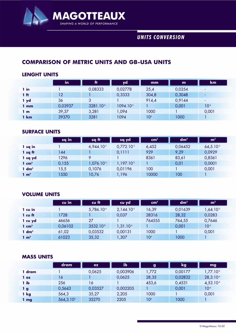
COMPARISON OF METRIC UNITS AND GB-USA UNITS
LENGHT UNITS
1 in 1 0,08333 0,02778 25,4 0,0254 -1 ft 12 1 0,3333 304,8 0,3048 -1 yd 36 3 1 914,4 0,9144 -1 mm 0,03937 3281.10-6 1094.10-6 1 0,001 10-6
1 m 39,37 3,281 1,094 1000 1 0,0011 km 39370 3281 1094 106 1000 1
SURFACE UNITS
1 sq in 1 6,944.10-3 0,772.10-3 6,452 0,06452 64,5.10-5
1 sq ft 144 1 0,1111 929 9,29 0,09291 sq yd 1296 9 1 8361 83,61 0,83611 cm2 0,155 1,076.10-3 1,197.10-3 1 0,01 0,00011 dm2 15,5 0,1076 0,01196 100 1 0,0011 m2 1550 10,76 1,196 10000 100 1
VOLUME UNITS
1 cu in 1 5,786.10-4 2,144.10-5 16,39 0,01639 1,64.10-5
1 cu ft 1728 1 0,037 28316 28,32 0,02831 cu yd 46656 27 1 764555 764,55 0,76461 cm3 0,06102 3532.10-8 1,31.10-6 1 0,001 10-6
1 dm3 61,02 0,03532 0,00131 1000 1 0,0011 m3 61023 35,32 1,307 106 1000 1
MASS UNITS
1 dram 1 0,0625 0,003906 1,772 0,00177 1,77.10-6
1 oz 16 1 0,0625 28,35 0,02832 28,3.10-6
1 ib 256 16 1 453,6 0,4531 4,53.10-4
1 g 0,5643 0,03527 0,002205 1 0,001 10-6
1 kg 564,3 35,27 2,205 1000 1 0,0011 mg 564,3.103 35270 2205 106 1000 1
kmmmmydftin
© Magotteaux 10.02
© Magotteaux 10.02
OTHER UNITS
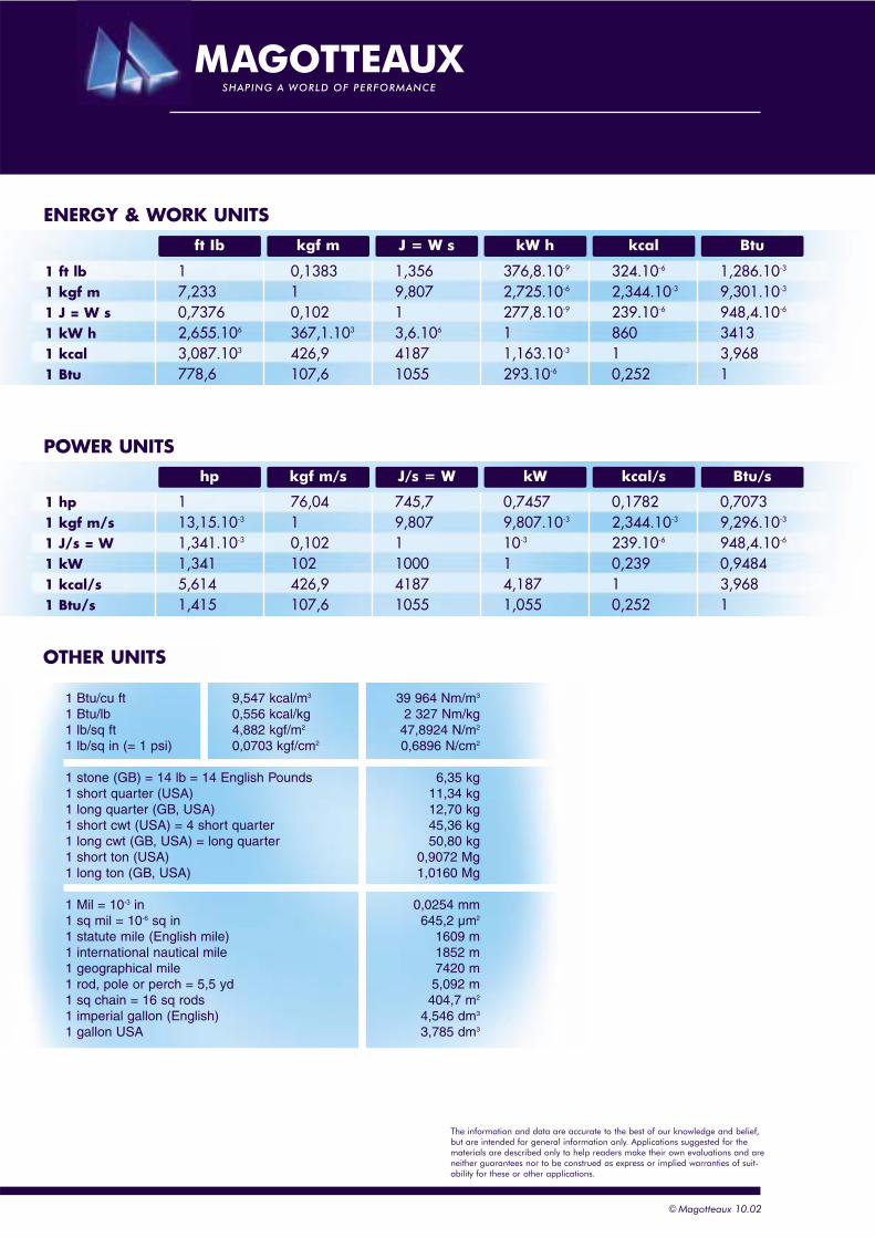
1 Btu/cu ft 9,547 kcal/m3 39 964 Nm/m3
1 Btu/lb 0,556 kcal/kg 2 327 Nm/kg1 lb/sq ft 4,882 kgf/m2 47,8924 N/m2
1 lb/sq in (= 1 psi) 0,0703 kgf/cm2 0,6896 N/cm2
1 stone (GB) = 14 lb = 14 English Pounds 6,35 kg1 short quarter (USA) 11,34 kg1 long quarter (GB, USA) 12,70 kg1 short cwt (USA) = 4 short quarter 45,36 kg1 long cwt (GB, USA) = long quarter 50,80 kg1 short ton (USA) 0,9072 Mg1 long ton (GB, USA) 1,0160 Mg
1 Mil = 10-3 in 0,0254 mm1 sq mil = 10-6 sq in 645,2 µm2
1 statute mile (English mile) 1609 m1 international nautical mile 1852 m1 geographical mile 7420 m1 rod, pole or perch = 5,5 yd 5,092 m1 sq chain = 16 sq rods 404,7 m2
1 imperial gallon (English) 4,546 dm3
1 gallon USA 3,785 dm3
Btu/skcal/skWJ/s = Wkgf m/shp
BtukcalkW hJ = W skgf mft Ib
ENERGY & WORK UNITS
1 ft lb 1 0,1383 1,356 376,8.10-9 324.10-6 1,286.10-3
1 kgf m 7,233 1 9,807 2,725.10-6 2,344.10-3 9,301.10-3
1 J = W s 0,7376 0,102 1 277,8.10-9 239.10-6 948,4.10-6
1 kW h 2,655.106 367,1.103 3,6.106 1 860 34131 kcal 3,087.103 426,9 4187 1,163.10-3 1 3,9681 Btu 778,6 107,6 1055 293.10-6 0,252 1
POWER UNITS
1 hp 1 76,04 745,7 0,7457 0,1782 0,70731 kgf m/s 13,15.10-3 1 9,807 9,807.10-3 2,344.10-3 9,296.10-3
1 J/s = W 1,341.10-3 0,102 1 10-3 239.10-6 948,4.10-6
1 kW 1,341 102 1000 1 0,239 0,94841 kcal/s 5,614 426,9 4187 4,187 1 3,9681 Btu/s 1,415 107,6 1055 1,055 0,252 1
The information and data are accurate to the best of our knowledge and belief,but are intended for general information only. Applications suggested for thematerials are described only to help readers make their own evaluations and areneither guarantees nor to be construed as express or implied warranties of suit-ability for these or other applications.
GRINDING MEDIA CHARACTERISTICS
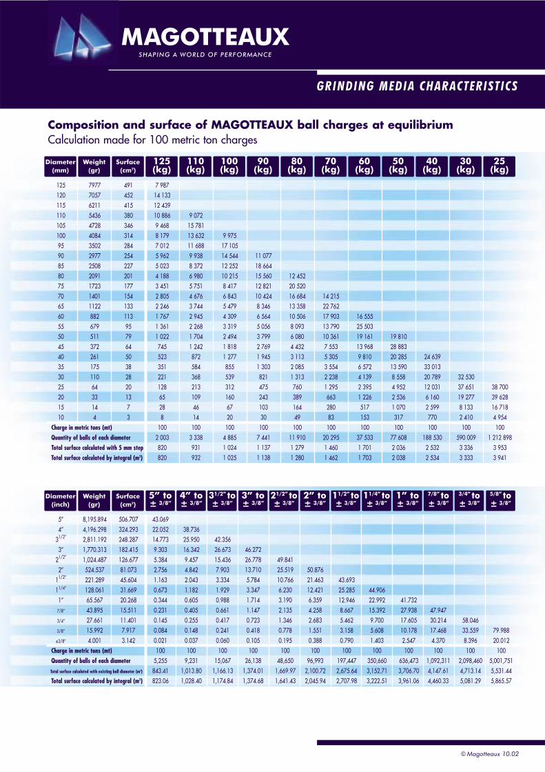
125 7977 491 7 987120 7057 452 14 133115 6211 415 12 439110 5436 380 10 886 9 072105 4728 346 9 468 15 781100 4084 314 8 179 13 632 9 97595 3502 284 7 012 11 688 17 10590 2977 254 5 962 9 938 14 544 11 07785 2508 227 5 023 8 372 12 252 18 66480 2091 201 4 188 6 980 10 215 15 560 12 45275 1723 177 3 451 5 751 8 417 12 821 20 52070 1401 154 2 805 4 676 6 843 10 424 16 684 14 21565 1122 133 2 246 3 744 5 479 8 346 13 358 22 76260 882 113 1 767 2 945 4 309 6 564 10 506 17 903 16 55555 679 95 1 361 2 268 3 319 5 056 8 093 13 790 25 50350 511 79 1 022 1 704 2 494 3 799 6 080 10 361 19 161 19 81045 372 64 745 1 242 1 818 2 769 4 432 7 553 13 968 28 88340 261 50 523 872 1 277 1 945 3 113 5 305 9 810 20 285 24 63935 175 38 351 584 855 1 303 2 085 3 554 6 572 13 590 33 01330 110 28 221 368 539 821 1 313 2 238 4 139 8 558 20 789 32 53025 64 20 128 213 312 475 760 1 295 2 395 4 952 12 031 37 651 38 70020 33 13 65 109 160 243 389 663 1 226 2 536 6 160 19 277 39 62815 14 7 28 46 67 103 164 280 517 1 070 2 599 8 133 16 71810 4 3 8 14 20 30 49 83 153 317 770 2 410 4 954
Charge in metric tons (mt) 100 100 100 100 100 100 100 100 100 100 100Quantity of balls of each diameter 2 003 3 338 4 885 7 441 11 910 20 295 37 533 77 608 188 530 590 009 1 212 898Total surface calculated with 5 mm step 820 931 1 024 1 137 1 279 1 460 1 701 2 036 2 532 3 336 3 953Total surface calculated by integral (m2) 820 932 1 025 1 138 1 280 1 462 1 703 2 038 2 534 3 333 3 941
Composition and surface of MAGOTTEAUX ball charges at equilibriumCalculation made for 100 metric ton charges
Diameter(mm)
Weight(gr)
Surface(cm2)
125(kg)
110(kg)
100(kg)
90(kg)
80(kg)
70(kg)
60(kg)
50(kg)
40(kg)
30(kg)
25(kg)
5” 8,195.894 506.707 43.0694” 4,196.298 324.293 22.052 38.736
31/2” 2,811.192 248.287 14.773 25.950 42.3563” 1,770.313 182.415 9.303 16.342 26.673 46.272
21/2” 1,024.487 126.677 5.384 9.457 15.436 26.778 49.8412” 524.537 81.073 2.756 4.842 7.903 13.710 25.519 50.876
11/2” 221.289 45.604 1.163 2.043 3.334 5.784 10.766 21.463 43.69311/4” 128.061 31.669 0.673 1.182 1.929 3.347 6.230 12.421 25.285 44.9061” 65.567 20.268 0.344 0.605 0.988 1.714 3.190 6.359 12.946 22.992 41.732
7/8” 43.895 15.511 0.231 0.405 0.661 1.147 2.135 4.258 8.667 15.392 27.938 47.9473/4” 27.661 11.401 0.145 0.255 0.417 0.723 1.346 2.683 5.462 9.700 17.605 30.214 58.0465/8” 15.992 7.917 0.084 0.148 0.241 0.418 0.778 1.551 3.158 5.608 10.178 17.468 33.559 79.988±3/8” 4.001 3.142 0.021 0.037 0.060 0.105 0.195 0.388 0.790 1.403 2.547 4.370 8.396 20.012
Charge in metric tons (mt) 100 100 100 100 100 100 100 100 100 100 100 100Quantity of balls of each diameter 5,255 9,231 15,067 26,138 48,650 96,993 197,447 350,660 636,473 1,092,311 2,098,460 5,001,751Total surface calculated with existing ball diameter (m2) 843.41 1,013.80 1,166.13 1,374.01 1,669.97 2,100.72 2,675.64 3,152.71 3,706.70 4,147.61 4,713.14 5,531.44Total surface calculated by integral (m2) 823.06 1,028.40 1,174.84 1,374.68 1,641.43 2,045.94 2,707.98 3,222.51 3,961.06 4,460.33 5,081.29 5,865.57
Diameter(inch)
Weight(gr)
Surface(cm2)
5” to± 3/8”
4” to± 3/8”
31/2” to± 3/8”
3” to± 3/8”
21/2” to± 3/8”
2” to± 3/8”
11/2” to± 3/8”
11/4” to± 3/8”
1” to± 3/8”
7/8” to± 3/8”
3/4” to± 3/8”
5/8” to± 3/8”
© Magotteaux 10.02
© Magotteaux 10.02
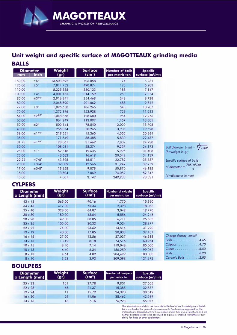
Unit weight and specific surface of MAGOTTEAUX grinding media
BALLS
CYLPEBS
150.00 ±6” 13,503.892 706.858 74 5.231125.00 ±5” 7,814.752 490.874 128 6.283110.00 5,325.535 380.133 188 7.147100.00 ±4” 4,001.153 314.159 250 7.854
90.00 ±31/2” 2,916.841 254.469 343 8.72880.00 2,048.590 201.062 488 9.81277.00 ±3” 1,826.658 186.265 548 10.20770.00 1,372.396 153.938 729 11.22264.00 ±21/2” 1,048.878 128.680 954 12.27660.00 864.249 113.097 1,157 13.08550.00 ±2” 500.144 78.540 2,000 15.70840.00 256.074 50.265 3,905 19.62838.00 ±11/2” 219.551 45.365 4,555 20.66435.00 171.549 38.485 5,830 22.43731.75 =11/4” 128.061 31.669 7,809 24.73030.00 108.031 28.274 9,257 26.17325.00 ±1” 62.518 19.635 15,996 31.40823.00 48.682 16.619 20,542 34.13922.22 =7/8” 43.895 15.511 22,782 35.33720.00 ±3/4” 32.009 12.566 31,242 39.25917.00 ±5/8” 19.658 9.079 50,870 46.18515.00 13.504 7.069 74,052 52.34710.00 4.001 3.142 249,938 78.531
Surface(cm2)
Number of ballsper metric ton
Specificsurface (m2/mt)
Diametermm inch
Weight(gr)
43 x 43 565.00 90.16 1,770 15.96034 x 43 417.00 75.34 2,398 18.06635 x 40 328.00 64.87 3,049 19.77030 x 30 180.00 43.64 5,556 24.24628 x 28 149.00 38.05 6,711 25.53525 x 25 105.00 30.32 9,524 28.87722 x 22 74.00 23.62 13,514 31.92019 x 19 48.00 17.85 20,833 37.18716 x 16 27.00 12.56 37,037 46.51813 x 13 13.42 8.18 74,516 60.95410 x 15 8.40 7.14 119,048 85.00010 x 13 6.40 6.34 156,250 99.062
8 x 13 4.64 4.89 204,499 100.0008 x 10 3.23 3.93 309,598 121.672
Ball diameter (mm) = (P=weight in gr)
Specific surface of balls
of diameter =
(d=diameter in mm)
Charge density: mt/M3
Balls . . . . . . . . . . . . . .4.65Cylpebs . . . . . . . . . . .4.70Cubes . . . . . . . . . . . . .5.50Rods . . . . . . . . . . . . . .6.20Ceramic Balls . . . . . . .2.05
Surface(cm2)
Number of cylpebsper metric ton
Specificsurface (m2/mt)
Diameterx Length (mm)
Weight(gr)
BOULPEBS
25 x 32 101 27.78 9,901 27.50522 x 28 65 21.37 15,385 32.87719 x 24 41 15.79 24,390 38.51216 x 20 26 11.06 38,462 42.53913 x 16 13 7.16 76,923 55.077
Surface(cm2)
Number of boulpebsper metric ton
Specificsurface (m2/mt)
Diameterx Length (mm)
Weight(gr)
The information and data are accurate to the best of our knowledge and belief,but are intended for general information only. Applications suggested for thematerials are described only to help readers make their own evaluations and areneither guarantees nor to be construed as express or implied warranties of suit-ability for these or other applications.
d785 m2/mt
3250P
WATER SLURRY PROPERTIES
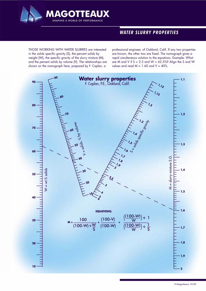
THOSE WORKING WITH WATER SLURRIES are interestedin the solids specific gravity (S), the percent solids byweight (W), the specific gravity of the slurry mixture (M),and the percent solids by volume (V). The relationships areshown on the nomograph here, prepared by F. Caplan, a
professional engineer, of Oakland, Calif. If any two propertiesare known, the other two are fixed. The nomograph gives arapid simultaneous solution to the equations. Example: Whatare M and V if S = 2.5 and W = 62.5%? Align the S and Wvalues and read M = 1.60 and V = 40%.
1,1
1,12
90
80
70
60
50
40
30
20
W =
wt.%
sol
ids
V =
solid
s, %
by
volu
me
S =
solid
s spe
cific
grav
ity
M =
slu
rry
mix
ture
S.G
.
10
90
80
70
60
50
40
30
20
10
1,15
1,2
1,3
1,4
1,5
1,6
1,71,8
1,92
2,5
3
45
6
1,2
1,3
1,4
1,5
1,6
1,7
1,8
1,9
2
( )100
EQUATIONS:
Water slurry propertiesF. Caplan, P.E., Oakland, Calif.
M = = =(100-W)+
+
+
(100-V)
(100-W)
(100-W)W
( )(100-W)W
WS
1S
1
© Magotteaux 10.02
© Magotteaux 10.02
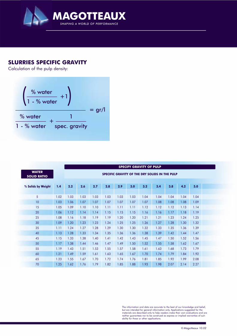
SLURRIES SPECIFIC GRAVITYCalculation of the pulp density:
( )% water
1 - % water+1
+1
spec. gravity
% water
1 - % water
= gr/l
% Solids by Weight 1.4 2.2 2.6 2.7 2.8 2.9 3.0 3.2 3.4 3.8 4.2 5.0
5 1.02 1.03 1.03 1.03 1.03 1.03 1.03 1.04 1.04 1.04 1.04 1.04
10 1.03 1.06 1.07 1.07 1.07 1.07 1.07 1.07 1.08 1.08 1.08 1.09
15 1.05 1.09 1.10 1.10 1.11 1.11 1.11 1.12 1.12 1.12 1.13 1.14
20 1.06 1.12 1.14 1.14 1.15 1.15 1.15 1.16 1.16 1.17 1.18 1.19
25 1.08 1.16 1.18 1.19 1.19 1.20 1.20 1.21 1.21 1.23 1.24 1.25
30 1.09 1.20 1.23 1.23 1.24 1.25 1.25 1.26 1.27 1.28 1.30 1.32
35 1.11 1.24 1.27 1.28 1.29 1.30 1.30 1.32 1.33 1.35 1.36 1.39
40 1.13 1.28 1.33 1.34 1.35 1.36 1.36 1.38 1.39 1.42 1.44 1.47
45 1.15 1.33 1.38 1.40 1.41 1.42 1.43 1.45 1.47 1.50 1.52 1.56
50 1.17 1.38 1.44 1.46 1.47 1.49 1.50 1.52 1.55 1.58 1.62 1.67
55 1.19 1.43 1.51 1.53 1.55 1.57 1.58 1.61 1.63 1.68 1.73 1.79
60 1.21 1.49 1.59 1.61 1.63 1.65 1.67 1.70 1.74 1.79 1.84 1.92
65 1.23 1.55 1.67 1.70 1.72 1.74 1.76 1.81 1.85 1.92 1.99 2.08
70 1.25 1.62 1.76 1.79 1.82 1.85 1.88 1.93 1.98 2.07 2.14 2.27
WATERSOLID RATIO
SPECIFY GRAVITY OF PULP
SPECIFIC GRAVITY OF THE DRY SOLIDS IN THE PULP
The information and data are accurate to the best of our knowledge and belief,but are intended for general information only. Applications suggested for thematerials are described only to help readers make their own evaluations and areneither guarantees nor to be construed as express or implied warranties of suit-ability for these or other applications.
1:1
Introduction
Intr
oduc
tion
BASICS IN MINERAL PROCESSING
“The practice of minerals processing is as old as human civilisation. Minerals andproducts derived from minerals have formed our development cultures from theflints of the Stone Age man to the uranium ores of Atomic Age”.
The ambition with this handbook, “Basics in Mineral Processing Equipment”, is notto give a full coverage of the subject above.
The intention is to give technicians involved in mineral operations practical anduseful information about the process equipment used, their systems and operationalenvironment.
The technical data given are basic, but will increase the understanding of theindividual machines, their functions and performances.
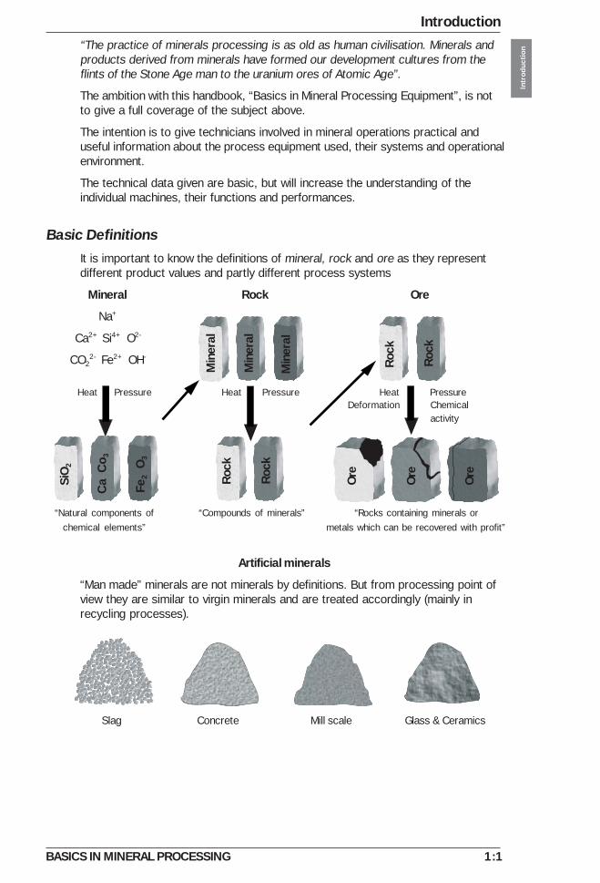
Basic DefinitionsIt is important to know the definitions of mineral, rock and ore as they representdifferent product values and partly different process systems
Mineral Rock Ore
Na+
Ca2+ Si4+ O2-
CO22- Fe2+ OH-
Heat Pressure Heat Pressure Heat PressureDeformation Chemical
activity
“Natural components of “Compounds of minerals” “Rocks containing minerals orchemical elements” metals which can be recovered with profit”
Artificial minerals
“Man made” minerals are not minerals by definitions. But from processing point ofview they are similar to virgin minerals and are treated accordingly (mainly inrecycling processes).
Slag Concrete Mill scale Glass & Ceramics
Min
eral
Min
eral
Min
eral
Rock
Rock
Rock
Rock
Ore
Ore
Ore
SiO
2
Ca
Co 3
Fe2
O3
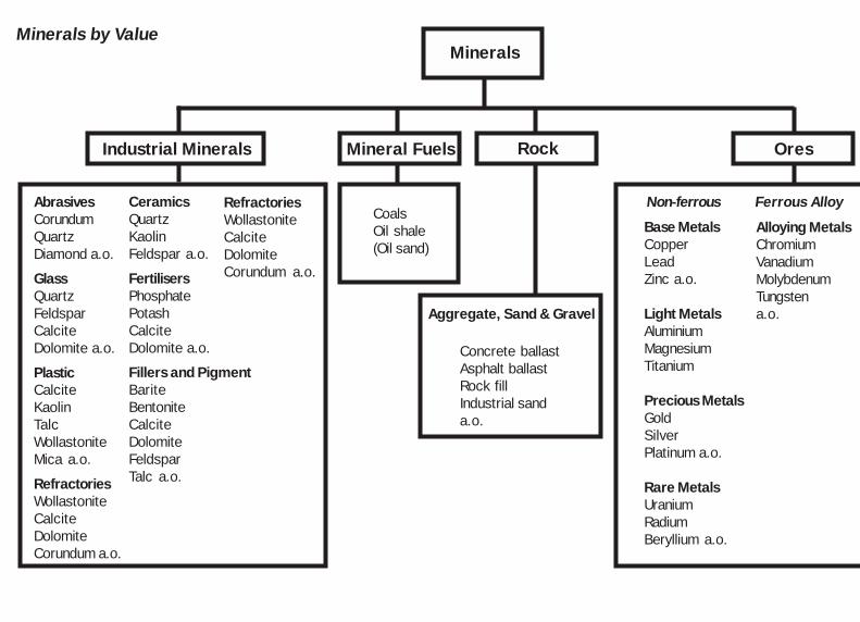
AbrasivesCorundumQuartzDiamond a.o.
GlassQuartzFeldsparCalciteDolomite a.o.
PlasticCalciteKaolinTalcWollastoniteMica a.o.
RefractoriesWollastoniteCalciteDolomiteCorundum a.o.
CeramicsQuartzKaolinFeldspar a.o.
FertilisersPhosphatePotashCalciteDolomite a.o.
Fillers and PigmentBariteBentoniteCalciteDolomiteFeldsparTalc a.o.
RefractoriesWollastoniteCalciteDolomiteCorundum a.o.
Base MetalsCopperLeadZinc a.o.
Light MetalsAluminiumMagnesiumTitanium
Precious MetalsGoldSilverPlatinum a.o.
Rare MetalsUraniumRadiumBeryllium a.o.
Alloying MetalsChromiumVanadiumMolybdenumTungstena.o.
Minerals by Value
CoalsOil shale(Oil sand)
Concrete ballastAsphalt ballastRock fillIndustrial sanda.o.
Aggregate, Sand & Gravel
Non-ferrous Ferrous Alloy
Industrial Minerals Mineral Fuels
Minerals
Rock Ores

1:3
Introduction
Intr
oduc
tion
BASICS IN MINERAL PROCESSING
The Process Frame of MineralsThe goal in mineral processing is to produce maximum value from a given rawmaterial. This goal can be a crushed product with certain size and shape ormaximum recovery of metals out of a complex ore.The technologies to achieve these goals are classical, complementary and welldefined.Below they are presented in the Process Frame of Minerals, classified accordingto their interrelations in product size and process environment (dry or wet).
Drilling (and blasting) is the technology of achieving primary fragmentation of“in situ” minerals. This is the starting point for most mineral processes with theexception of natural minerals in the form of sand and gravel.
Crushing and screening is the first controlled size reduction stage in theprocess. This is the main process in aggregate production and a preparationprocess for further size reduction.
Grinding is the stage of size reduction (wet or dry) where the liberation size forindividual minerals can be reached. By further size reduction filler (mineralpowder) is produced.
Slurry processing includes the technologies for wet processing of mineralfractions.
Pyro processing includes the technologies for upgrading of the mineral fractionsby drying, calcining or sintering.
Materials handling includes the technologies for moving the process flow (dry)forward by loading, transportation, storage and feeding.
Compaction of minerals includes the technologies for moving and densifyingminerals by vibration, impaction and pressure, mainly used in constructionapplications.
Size 1m 100 mm 10 mm 1 mm 100 micron 10 micron 1 micron8
1:4
IntroductionIn
trod
uctio
n
BASICS IN MINERAL PROCESSING
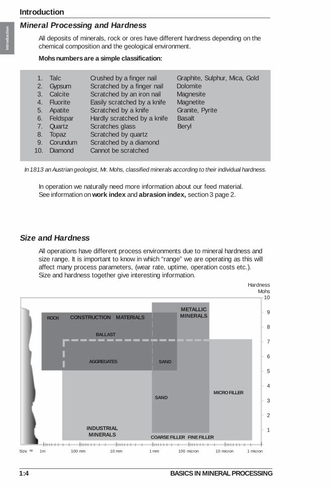
In 1813 an Austrian geologist, Mr. Mohs, classified minerals according to their individual hardness.
Crushed by a finger nailScratched by a finger nailScratched by an iron nailEasily scratched by a knifeScratched by a knifeHardly scratched by a knifeScratches glassScratched by quartzScratched by a diamondCannot be scratched
Graphite, Sulphur, Mica, Gold Dolomite Magnesite Magnetite Granite, Pyrite Basalt Beryl
Mineral Processing and HardnessAll deposits of minerals, rock or ores have different hardness depending on thechemical composition and the geological environment.
Mohs numbers are a simple classification:
Size and HardnessAll operations have different process environments due to mineral hardness andsize range. It is important to know in which “range” we are operating as this willaffect many process parameters, (wear rate, uptime, operation costs etc.).Size and hardness together give interesting information.
In operation we naturally need more information about our feed material.See information on work index and abrasion index, section 3 page 2.
1. Talc2. Gypsum3. Calcite4. Fluorite5. Apatite6. Feldspar7. Quartz8. Topaz9. Corundum
10. Diamond
10
9
8
7
6
5
4
3
2
1
HardnessMohs
INDUSTRIALMINERALS
ROCK
BALLAST
SAND
METALLICMINERALSCONSTRUCTION MATERIALS
AGGREGATES
COARSE FILLER FINE FILLER
SAND
MICRO FILLER
Size 1m 100 mm 10 mm 1 mm 100 micron 10 micron 1 micron8

1:5
Introduction
Intr
oduc
tion
BASICS IN MINERAL PROCESSING
The Stress Forces of Rock MechanicsBeside size and hardness, the classical stress forces of rock mechanics are thefundamentals in most of what we do in mineral processing. They guide us inequipment design, in systems layout, in wear protection etc. They are alwaysaround and they always have to be considered.
Tensile Compression
Impaction Shearing
Attrition
Product Handbook 2:1
Minerals in Operation
BASICS IN MINERAL PROCESSING
Min
eral
s in
Ope
rati
on
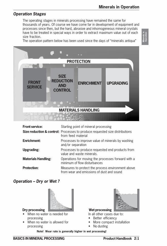
Operation StagesThe operating stages in minerals processing have remained the same forthousands of years. Of course we have come far in development of equipment andprocesses since then, but the hard, abrasive and inhomogeneous mineral crystalshave to be treated in special ways in order to extract maximum value out of eachsize fraction.The operation pattern below has been used since the days of “mineralis antiqua”
Front service: Starting point of mineral processingSize reduction & control: Processes to produce requested size distributions
from feed materialEnrichment: Processes to improve value of minerals by washing
and/or separationUpgrading: Processes to produce requested end products from
value and waste minerals.Materials Handling: Operations for moving the processes forward with a
minimum of flow disturbancesProtection: Measures to protect the process environment above
from wear and emissions of dust and sound
Operation – Dry or Wet ?
FRONTSERVICE
SIZEREDUCTION
ANDCONTROL
ENRICHMENT UPGRADING
MATERIALS HANDLING
PROTECTION
Note! Wear rate is generally higher in wet processing!
In all other cases due to:• Better efficiency• More compact installation• No dusting
• When no water is needed forprocessing
• When no water is allowed forprocessing
Dry processing Wet processing

2:2 Product Handbook
Minerals in Operation
BASICS IN MINERAL PROCESSING
Min
eral
s in
Ope
rati
on
Mining and Quarry FrontsThe mining and quarry fronts are the starting points for recovery of rock andmineral values from surface and underground deposits.
Operations are drilling (blasting), primary crushing (optional) and materialshandling, dry and wet.
UndergroundNatural Fronts
In the glacial, alluvial and marine fronts nature has done most of the primary sizereduction work.
Raw material such as gravel, sand and clay are important for processing ofconstruction ballast, metals and industrial mineral fillers.
Operations are materials handling (wet and dry) and front crushing (optional).
Glacial
Glacial sand and gravel occur in areas which are – or have been – covered byice. The material is rounded and completely unsorted with an heterogeneous sizedistribution which ranges from boulders larger than 1 m (3 ft) down to silt (2-20microns). Clay contamination is concentrated in well defined layers.
Open pit
Mining and quarrying

Product Handbook 2:3
Minerals in Operation
BASICS IN MINERAL PROCESSING
Min
eral
s in
Ope
rati
on
Marine
Marine sand and gravel often have a more limited size distribution than othertypes of sand and gravel. The minerals in marine sand and gravel have survivedthousands – or even millions of years – of natural attrition, from erosion in themountain ranges and grinding during transport down to the sea. The particles havebecome well rounded and the clay content is extremely low. Marine fronts are incertain areas hosting heavy minerals like hematite, magnetite, rutile a.o.
Alluvial
The size of alluvial sand and gravel depends on the flow velocity of the water,among other things. Normally the maximum size is around 100 mm (4”). Alluvialsand and gravel have a homogeneous size distribution and larger particles oftenhave high silica content. The clay content is often high, normally in the range of5 to 15 %. Alluvial fronts are in certain areas hosting gold, tin and preciousstones.
2:4 Product Handbook
Minerals in Operation
BASICS IN MINERAL PROCESSING
Min
eral
s in
Ope
rati
on
Size Reduction
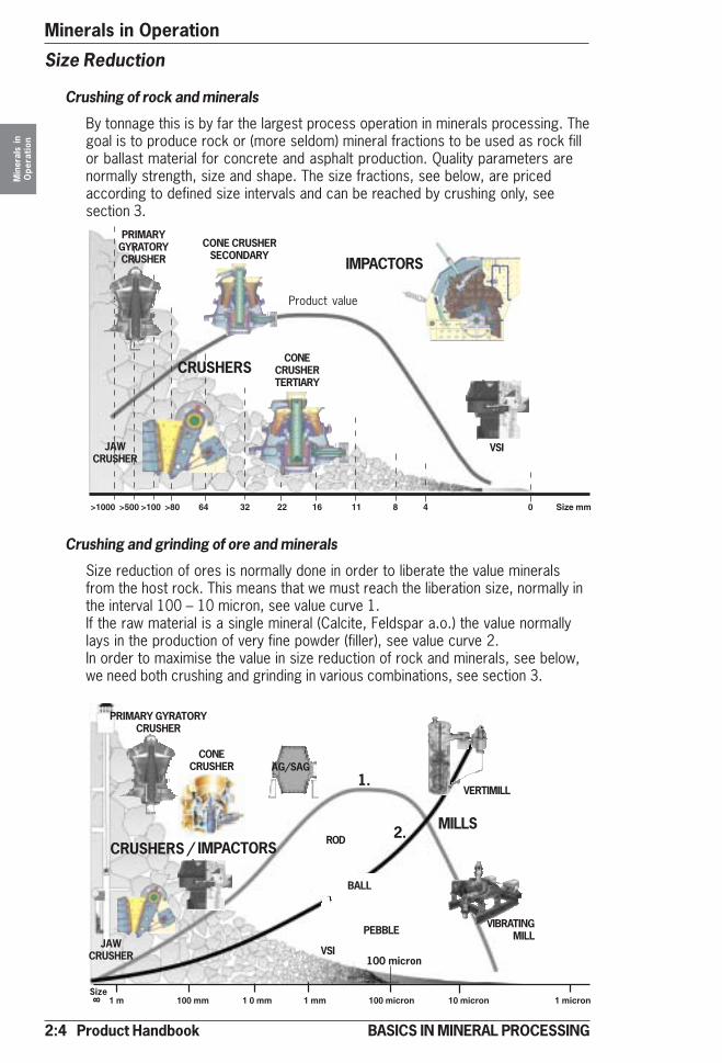
Crushing of rock and minerals
By tonnage this is by far the largest process operation in minerals processing. Thegoal is to produce rock or (more seldom) mineral fractions to be used as rock fillor ballast material for concrete and asphalt production. Quality parameters arenormally strength, size and shape. The size fractions, see below, are pricedaccording to defined size intervals and can be reached by crushing only, seesection 3.
>1000 >500 >100 >80 64 32 22 16 11 8 4 0 Size mm
PRIMARYGYRATORYCRUSHER
JAWCRUSHER
CRUSHERS
CONE CRUSHERSECONDARY
VSI
CONECRUSHERTERTIARY
Product value
1 m 100 mm 1 0 mm 1 mm 100 micron 10 micron 1 micron
100 micron
PRIMARY GYRATORYCRUSHER
JAWCRUSHER VSI
CONECRUSHER
CRUSHERS / IMPACTORS
MILLS
VIBRATINGMILL
VERTIMILL
Crushing and grinding of ore and minerals
Size reduction of ores is normally done in order to liberate the value mineralsfrom the host rock. This means that we must reach the liberation size, normally inthe interval 100 – 10 micron, see value curve 1.If the raw material is a single mineral (Calcite, Feldspar a.o.) the value normallylays in the production of very fine powder (filler), see value curve 2.In order to maximise the value in size reduction of rock and minerals, see below,we need both crushing and grinding in various combinations, see section 3.
AG/SAG
PEBBLE
BALL
ROD
1.
2.
Size
8
IMPACTORS
Product Handbook 2:5
Minerals in Operation
BASICS IN MINERAL PROCESSING
Min
eral
s in
Ope
rati
on
1 m 10 mm 10 mm 1 mm 100 micron 10 micron 1 micron
100 micron
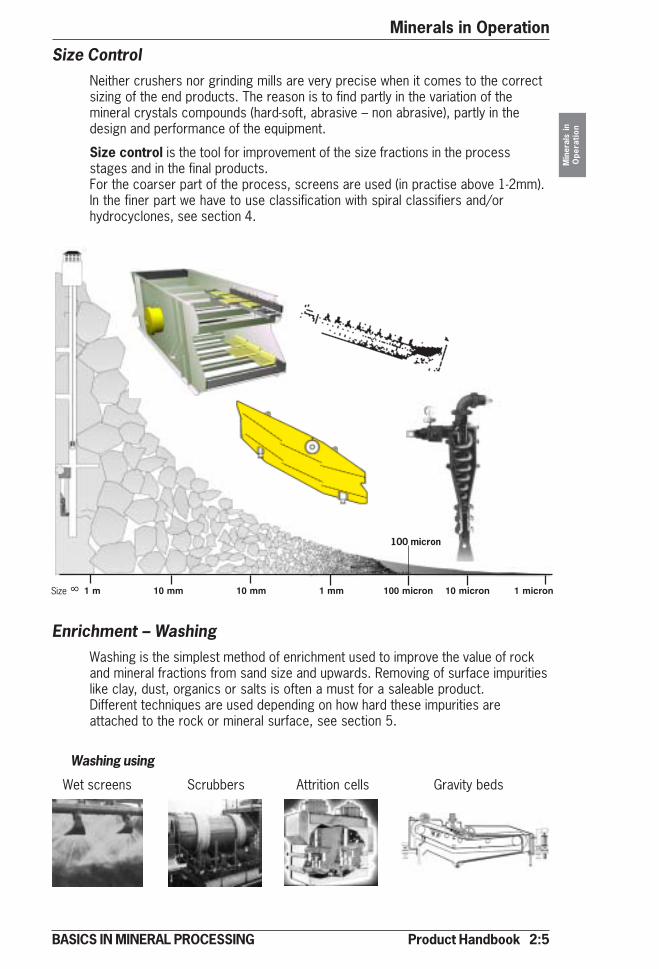
Size ControlNeither crushers nor grinding mills are very precise when it comes to the correctsizing of the end products. The reason is to find partly in the variation of themineral crystals compounds (hard-soft, abrasive – non abrasive), partly in thedesign and performance of the equipment.
Size control is the tool for improvement of the size fractions in the processstages and in the final products.For the coarser part of the process, screens are used (in practise above 1-2mm).In the finer part we have to use classification with spiral classifiers and/orhydrocyclones, see section 4.
Enrichment – WashingWashing is the simplest method of enrichment used to improve the value of rockand mineral fractions from sand size and upwards. Removing of surface impuritieslike clay, dust, organics or salts is often a must for a saleable product.Different techniques are used depending on how hard these impurities areattached to the rock or mineral surface, see section 5.
Washing using
Wet screens Scrubbers Attrition cells Gravity beds
Size 8
2:6 Product Handbook
Minerals in Operation
BASICS IN MINERAL PROCESSING
Min
eral
s in
Ope
rati
on
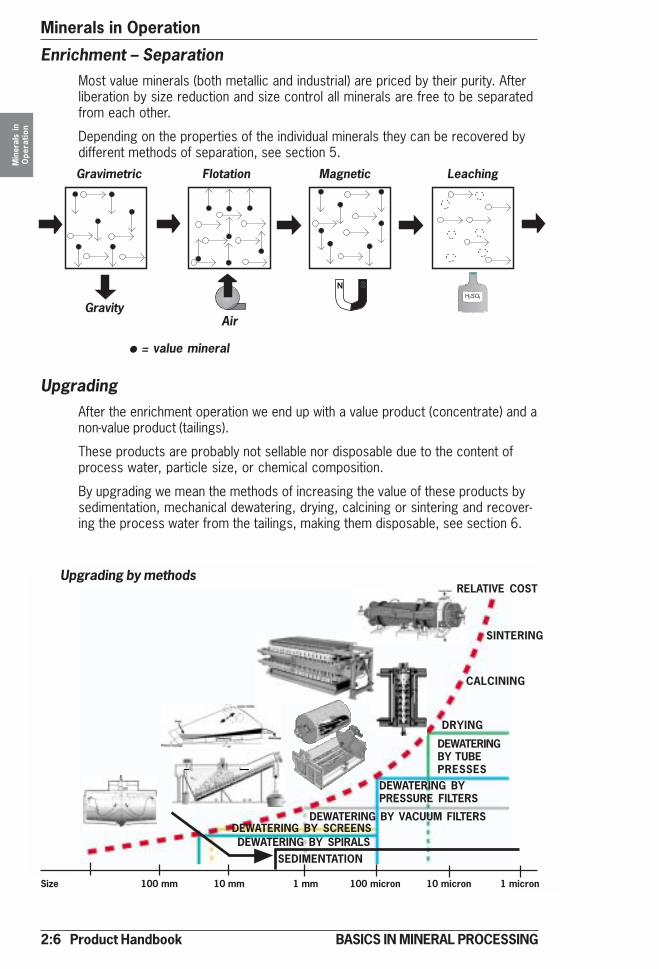
Enrichment – SeparationMost value minerals (both metallic and industrial) are priced by their purity. Afterliberation by size reduction and size control all minerals are free to be separatedfrom each other.
Depending on the properties of the individual minerals they can be recovered bydifferent methods of separation, see section 5.
DEWATERING BYPRESSURE FILTERS
DEWATERING BY VACUUM FILTERS
SEDIMENTATION
SINTERING
DEWATERINGBY TUBEPRESSES
DEWATERING BY SCREENSDEWATERING BY SPIRALS
Size 100 mm 10 mm 1 mm 100 micron 10 micron 1 micron
UpgradingAfter the enrichment operation we end up with a value product (concentrate) and anon-value product (tailings).
These products are probably not sellable nor disposable due to the content ofprocess water, particle size, or chemical composition.
By upgrading we mean the methods of increasing the value of these products bysedimentation, mechanical dewatering, drying, calcining or sintering and recover-ing the process water from the tailings, making them disposable, see section 6.
Gravimetric Flotation Magnetic Leaching
� ������ �
Upgrading by methods
DRYING
GravityAir
• = value mineral
CALCINING
RELATIVE COST

Product Handbook 2:7
Minerals in Operation
BASICS IN MINERAL PROCESSING
Min
eral
s in
Ope
rati
on
Materials HandlingWithout a proper set up for materials handling no processing system willperform. Different process stages may be in various locations, may havevarious feed conditions, are on different shift cycles etc.
Materials handling of dry material is based on the operations of loadíng,unloading, transportation, storing and feeding, see section 7.
Materials handling of wet material, called slurry handling is also based on theoperations of transportation (by slurry pumps and hoses), feeding (by slurrypumps) and storage (by slurry agitation), see section 8.
�����
����
���
����
��� �
�
������
�
�
������� �����
�������
�����
���������� �
Dry handling
Slurry handling
2:8 Product Handbook
Minerals in Operation
BASICS IN MINERAL PROCESSING
Min
eral
s in
Ope
rati
on
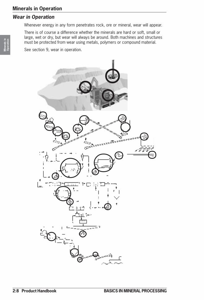
Wear in OperationWhenever energy in any form penetrates rock, ore or mineral, wear will appear.
There is of course a difference whether the minerals are hard or soft, small orlarge, wet or dry, but wear will always be around. Both machines and structuresmust be protected from wear using metals, polymers or compound material.
See section 9, wear in operation.
Product Handbook 2:9
Minerals in Operation
BASICS IN MINERAL PROCESSING
Min
eral
s in
Ope
rati
on
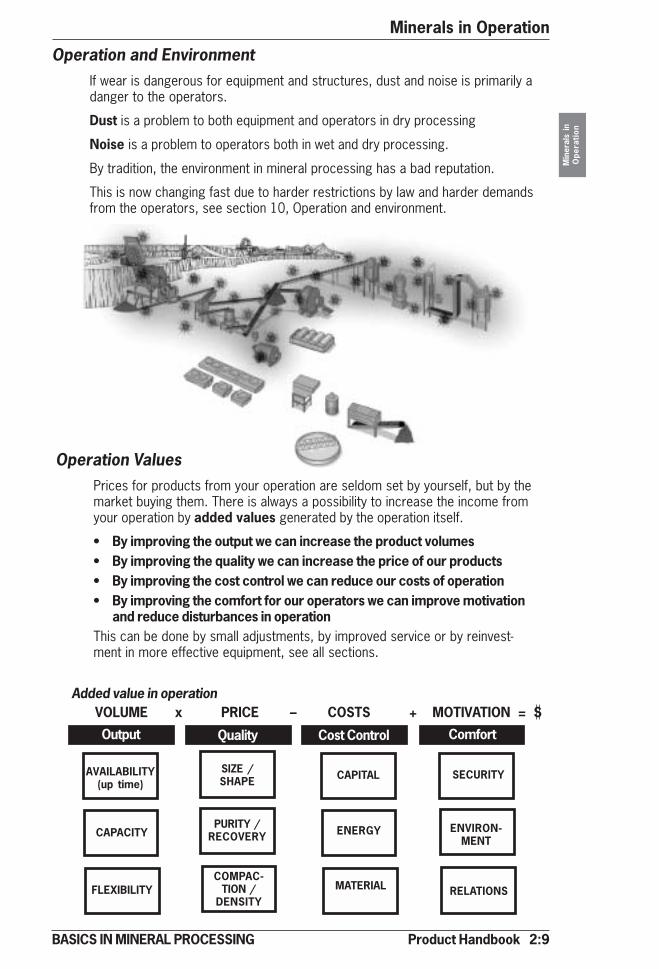
Operation and EnvironmentIf wear is dangerous for equipment and structures, dust and noise is primarily adanger to the operators.
Dust is a problem to both equipment and operators in dry processing
Noise is a problem to operators both in wet and dry processing.
By tradition, the environment in mineral processing has a bad reputation.
This is now changing fast due to harder restrictions by law and harder demandsfrom the operators, see section 10, Operation and environment.
VOLUME x PRICE – COSTS + MOTIVATION = S
Operation ValuesPrices for products from your operation are seldom set by yourself, but by themarket buying them. There is always a possibility to increase the income fromyour operation by added values generated by the operation itself.
• By improving the output we can increase the product volumes• By improving the quality we can increase the price of our products• By improving the cost control we can reduce our costs of operation• By improving the comfort for our operators we can improve motivation
and reduce disturbances in operationThis can be done by small adjustments, by improved service or by reinvest-ment in more effective equipment, see all sections.
Added value in operation
Output Quality Cost Control Comfort
AVAILABILITY(up time)
SIZE /SHAPE CAPITAL SECURITY
CAPACITYPURITY /
RECOVERY ENERGY ENVIRON-MENT
FLEXIBILITYCOMPAC-
TION /DENSITY
MATERIAL RELATIONS
Product Handbook 3:1
Size Reduction
Size
Red
uctio
n
BASICS IN MINERAL PROCESSING
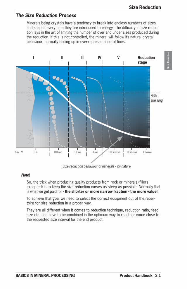
The Size Reduction ProcessMinerals being crystals have a tendency to break into endless numbers of sizesand shapes every time they are introduced to energy. The difficulty in size reduc-tion lays in the art of limiting the number of over and under sizes produced duringthe reduction. If this is not controlled, the mineral will follow its natural crystalbehaviour, normally ending up in over-representation of fines.
Size reduction behaviour of minerals - by nature
Note!
So, the trick when producing quality products from rock or minerals (fillersexcepted) is to keep the size reduction curves as steep as possible. Normally thatis what we get paid for - the shorter or more narrow fraction - the more value!
To achieve that goal we need to select the correct equipment out of the reper-toire for size reduction in a proper way.
They are all different when it comes to reduction technique, reduction ratio, feedsize etc. and have to be combined in the optimum way to reach or come close tothe requested size interval for the end product.
I II III IV V Reductionstage
80%passing
Size 1m 100 mm 10 mm 1 mm 100 micron 10 micron 1 micron8

3:2 Product Handbook
Size ReductionSi
ze R
educ
tion
BASICS IN MINERAL PROCESSING
Impact Work Index Wi Abrasion index = Ai
Material Wi value
Basalt 20 ± 4Diabase 19 ± 4Dolomite 12 ± 3Iron-ore, Hematite 11 ± 3Iron-ore, Magnetite 8 ± 3Gabbro 20 ± 3Gneiss 16 ± 4Granite 16 ± 6Greywacke 18 ± 3Limestone 12 ± 3Quartzite 16 ± 3Porphyry 18 ± 3Sandstone 10 ± 3Syenite 19 ± 4
Material Ai value
Basalt 0,200 ± 0,20Diabase 0,300 ± 0,10Dolomite 0,010 ± 0,05Iron-ore, Hematite 0,500 ± 0,30Iron-ore, Magnetite 0,200 ± 0,10Gabbro 0,400 ± 0,10Gneiss 0,500 ± 0,10Granite 0,550 ± 0,10Greywacke 0,300 ± 0,10Limestone 0,001 – 0,03Quartzite 0,750 ± 0,10Porphyry 0,100 – 0,90Sandstone 0,600 ± 0,20Syenite 0,400 ± 0,10
INFLUENCING
• Size reduction • Energy requirement• Machine status
INFLUENCING
• Wear rate
Feed MaterialAll operations in size reduction, both crushing and grinding are of course deter-mined by the feed characteristics of the minerals (rock/ore) moving into thecircuit. The key parameters we need are the “crushability or grindability”, alsocalled work index and the “wear profile”, called abrasion index. Values for sometypical feed materials from crushing of rocks, minerals and ore are tabulatedbelow.
Reduction RatioAs seen above all size reduction operations are performed in stages. All equip-ment involved, crushers or grinding mills have different relation between feed anddischarge sizes. This is called reduction ratio. Typical values below.
10-15
Compression crushers Impactors (horizontal type)
Jaw 3-4
Gyratory 3-4
Cone 4-5
3-8
Grinding mills (tumbling type)
Rod 100
Ball 1000
AG & SAG 5000
Impactors (vertical type)
Regarding Work Index (Bond) for grinding, see 3:24.
Size Reduction
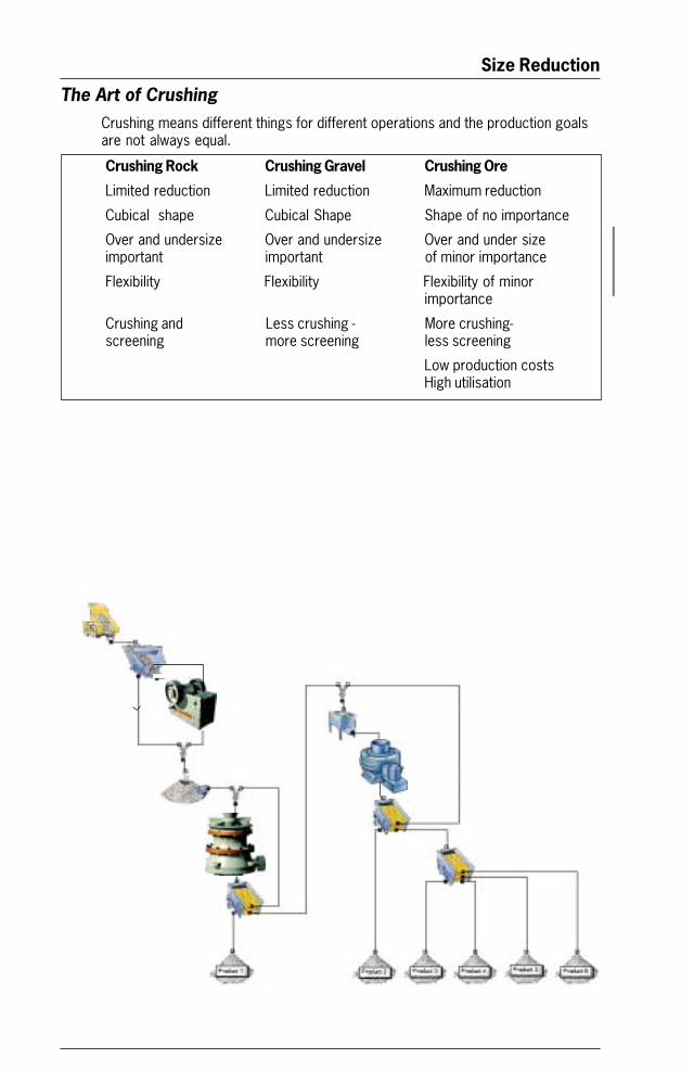
The Art of CrushingCrushing means different things for different operations and the production goalsare not always equal.
Crushing Rock Crushing Gravel Crushing Ore
Limited reduction Limited reduction Maximum reduction
Cubical shape Cubical Shape Shape of no importance
Over and undersize Over and undersize Over and under sizeimportant important of minor importance
Flexibility Flexibility Flexibility of minorimportance
Crushing and Less crushing - More crushing-screening more screening less screening
Low production costsHigh utilisation
Size Reduction
Size
Red
uctio
n
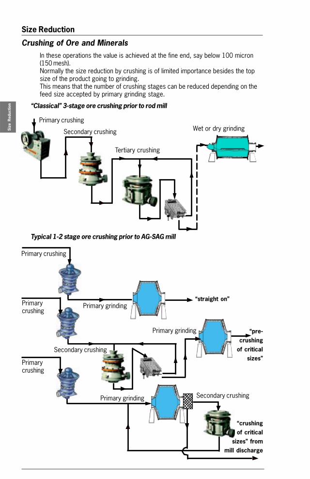
Crushing of Ore and MineralsIn these operations the value is achieved at the fine end, say below 100 micron(150 mesh).Normally the size reduction by crushing is of limited importance besides the topsize of the product going to grinding.This means that the number of crushing stages can be reduced depending on thefeed size accepted by primary grinding stage.
“Classical” 3-stage ore crushing prior to rod mill
Typical 1-2 stage ore crushing prior to AG-SAG mill
Primary grinding
Primary grinding
Primary grinding Secondary crushing
“straight on”
“pre-crushing
of criticalsizes”
Primary crushing
Primarycrushing
Secondary crushing
Primarycrushing
“crushingof critical
sizes” frommill discharge
Tertiary crushing
Wet or dry grindingPrimary crushing
Secondary crushing
Size Reduction
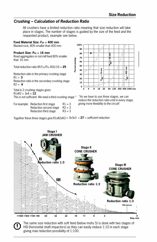
Feed Material Size: F80 = 400 mmBlasted rock, 80% smaller than 400 mm
Product Size: P80 = 16 mmRoad aggregates or rod mill feed 80% smallerthan 16 mm
Total reduction ratio (R) F80/P80 400/16 = 25
Reduction ratio in the primary crushing stageR1 = 3Reduction ratio in the secondary crushing stageR2 = 4
Total in 2 crushing stages givesR1xR2 = 3x4 = 12This is not sufficient. We need a third crushing stage.*
For example: Reduction first stage R1 = 3Reduction second stage R2 = 3Reduction third stage R3 = 3
Together these three stages give R1xR2xR3 = 3x3x3 = 27 = sufficient reduction
Crushing – Calculation of Reduction RatioAll crushers have a limited reduction ratio meaning that size reduction will takeplace in stages. The number of stages is guided by the size of the feed and therequested product, example see below.
The same size reduction with soft feed (below mohs 5) is done with two stages ofHSI (horizontal shaft impactors) as they can easily reduce 1:10 in each stagegiving max reduction possibility of 1:100.
100 micron
JAW CRUSHER
CONE CRUSHER
CONE CRUSHER
Reduction ratio 1:3
Reduction ratio 1:3
Stage I
Stage II
Stage III
I
II
III
Reduction ratio 1:3
>1000 >500 >100 >80 64 32 22 16 11 8 4 0 Size mm
*As we have to use three stages, we canreduce the reduction ratio a bit in every stage,giving more flexibility to the circuit!
����
��
��
��
��
��
�
�
��
��
���������������������������������������������������������
���
����
����
����
�����
����
�����
����
� ����
����
Size Reduction
Size
Red
uctio
n
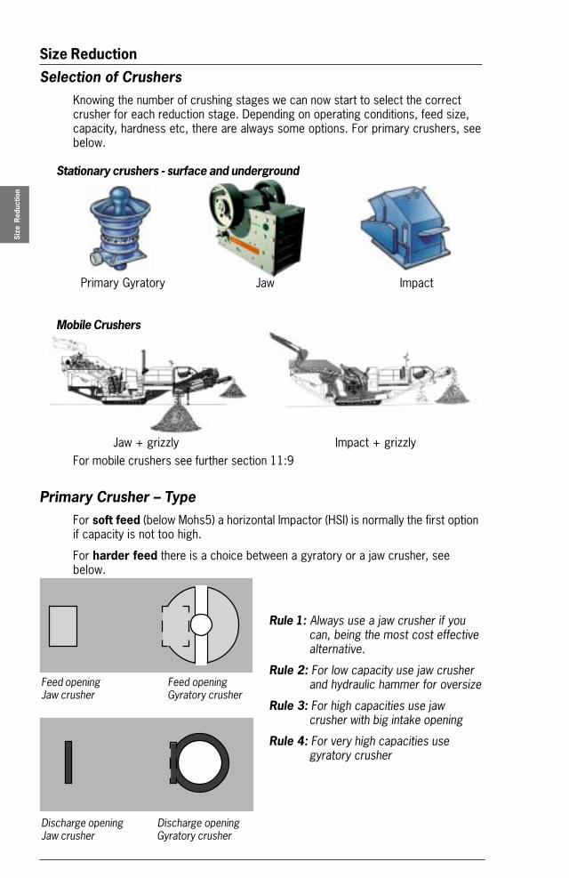
Selection of CrushersKnowing the number of crushing stages we can now start to select the correctcrusher for each reduction stage. Depending on operating conditions, feed size,capacity, hardness etc, there are always some options. For primary crushers, seebelow.
Stationary crushers - surface and underground
Mobile Crushers
For mobile crushers see further section 11:9
Primary Crusher – TypeFor soft feed (below Mohs5) a horizontal Impactor (HSI) is normally the first optionif capacity is not too high.
For harder feed there is a choice between a gyratory or a jaw crusher, seebelow.
Primary Gyratory
Feed opening Feed openingJaw crusher Gyratory crusher
Discharge opening Discharge openingJaw crusher Gyratory crusher
Rule 1: Always use a jaw crusher if youcan, being the most cost effectivealternative.
Rule 2: For low capacity use jaw crusherand hydraulic hammer for oversize
Rule 3: For high capacities use jawcrusher with big intake opening
Rule 4: For very high capacities usegyratory crusher
Jaw Impact
Jaw + grizzly Impact + grizzly
Size Reduction
200 400 600 800 1000 1200 1400 1600 1800 2000
S 42 - 65S 48 - 74
S 54 - 75S 60 - 89 S 60 -
100
Capacity t/h
Feed top size mm (inch: divide by 25)
1500
1000
500
1000 2000 3000 4000
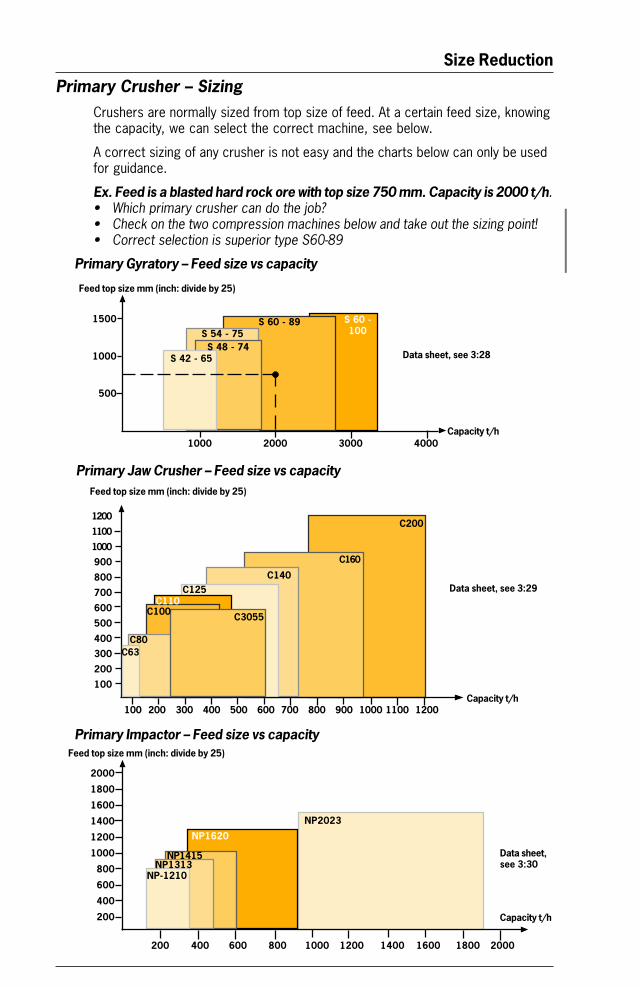
Primary Crusher – SizingCrushers are normally sized from top size of feed. At a certain feed size, knowingthe capacity, we can select the correct machine, see below.
A correct sizing of any crusher is not easy and the charts below can only be usedfor guidance.
Ex. Feed is a blasted hard rock ore with top size 750 mm. Capacity is 2000 t/h.• Which primary crusher can do the job?• Check on the two compression machines below and take out the sizing point!• Correct selection is superior type S60-89
Primary Gyratory – Feed size vs capacity
Primary Jaw Crusher – Feed size vs capacity
Primary Impactor – Feed size vs capacity
Capacity t/h
Feed top size mm (inch: divide by 25)
1200
1100
1000
900
800
700
600
500
400
300
200
100
100 200 300 400 500 600 700 800 900 1000 1100 1200
Feed top size mm (inch: divide by 25)
C110C125
C140
C160
C200
C80
2000
1800
1600
1400
1200
1000
800
600
400
200 Capacity t/h
NP2023
NP1415NP1313
NP1620
NP-1210
C3055
C63
Data sheet, see 3:28
Data sheet, see 3:29
Data sheet,see 3:30
C100
Size Reduction
Size
Red
uctio
n
Yesterday Today Demands
Jaw Crusher
• Big feed opening• High capacity• Controlled feed• Shape
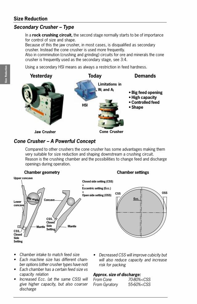
Secondary Crusher – TypeIn a rock crushing circuit, the second stage normally starts to be of importancefor control of size and shape.Because of this the jaw crusher, in most cases, is disqualified as secondarycrusher. Instead the cone crusher is used more frequently.Also in comminution (crushing and grinding) circuits for ore and minerals the conecrusher is frequently used as the secondary stage, see 3:4.
Using a secondary HSI means as always a restriction in feed hardness.
HSI
Cone Crusher
Cone Crusher – A Powerful ConceptCompared to other crushers the cone crusher has some advantages making themvery suitable for size reduction and shaping downstream a crushing circuit.Reason is the crushing chamber and the possibilities to change feed and dischargeopenings during operation.
Chamber geometry Chamber settings
Nip angle
Mantle
Upper concave
CSS,ClosedSideSetting
OSSCSS
Closed side setting (CSS)+Eccentric setting (Ecc.)=Open side setting (OSS)
• Chamber intake to match feed size• Each machine size has different cham-
ber options (other crusher types have not)• Each chamber has a certain feed size vs
capacity relation• Increased Ecc. (at the same CSS) will
give higher capacity, but also coarserdischarge
• Decreased CSS will improve cubicity butwill also reduce capacity and increaserisk for packing
Approx. size of discharge:From Cone 70-80%<CSSFrom Gyratory 55-60%<CSS
Ecc.
Limitations inWi and Ai
Mantle
Concave
CSS,ClosedSideSetting
Lowerconcave
Size Reduction
Capacity t/h
Feed top size mm (inch: divide by 25)
250 500 750 1000
400
300
200
100
GP500S
GP300SGP200S
GP100S
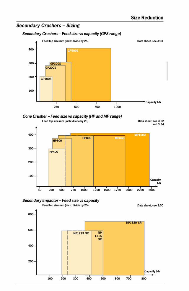
Cone Crusher – Feed size vs capacity (HP and MP range)
Secondary Crushers – Feed size vs capacity (GPS range)
Feed top size mm (inch: divide by 25)
Capacityt/h
HP400
50 250 500 750 1000 1250 1500 1750 2000 2250 5000
MP800HP800HP500
Feed top size mm (inch: divide by 25)
800
600
400
200
100 200 300 400 500 600 700 800
Secondary Impactor – Feed size vs capacity
NP1315
SR
NP1520 SR
Capacity t/h
Secondary Crushers – Sizing
Data sheet, see 3:31
Data sheet, see 3:32and 3:34
Data sheet, see 3:30
MP1000400
300
200
100
NP1213 SR
Size Reduction
Size
Red
uctio
n
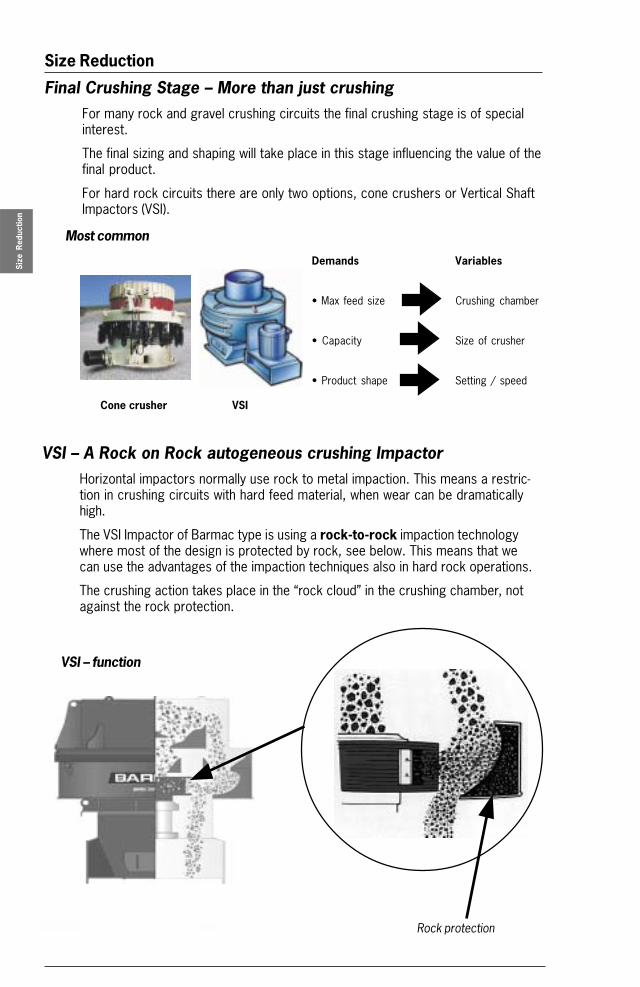
Final Crushing Stage – More than just crushingFor many rock and gravel crushing circuits the final crushing stage is of specialinterest.
The final sizing and shaping will take place in this stage influencing the value of thefinal product.
For hard rock circuits there are only two options, cone crushers or Vertical ShaftImpactors (VSI).
VSI – A Rock on Rock autogeneous crushing ImpactorHorizontal impactors normally use rock to metal impaction. This means a restric-tion in crushing circuits with hard feed material, when wear can be dramaticallyhigh.
The VSI Impactor of Barmac type is using a rock-to-rock impaction technologywhere most of the design is protected by rock, see below. This means that wecan use the advantages of the impaction techniques also in hard rock operations.
The crushing action takes place in the “rock cloud” in the crushing chamber, notagainst the rock protection.
VSI – function
Most common
Demands Variables
• Max feed size Crushing chamber
• Capacity Size of crusher
• Product shape Setting / speed
Cone crusher VSI
Rock protection
Size Reduction
MP1000
25 125 250 375 500 625 750 900
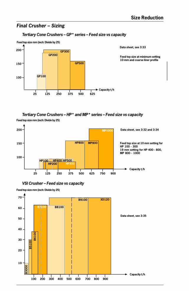
Tertiary Cone Crushers – GP* series – Feed size vs capacity
Feed top size at 10 mm setting forHP 100 - 30019 mm setting for HP 400 - 800,MP 800 - 1000
Final Crusher – Sizing
VSI Crusher – Feed size vs capacity
Data sheet, see 3:33
Tertiary Cone Crushers – HP* and MP* series – Feed size vs capacity
Feed top size at minimum setting10 mm and coarse liner profile
200
150
100
Capacity t/h
Data sheet, see 3:32 and 3:34
MP800
GP500
GP300
25 125 250 375 500 625
GP200
Capacity t/h
GP100
HP800
HP500HP400HP300HP200
HP100
Feed top size mm (inch: Divide by 25)
Data sheet, see 3:35
100 200 300 400 500 600 700 800 900
70
60
50
40
30
20
10
XD120B9100
B8100
B51
00
B61
00
B30
00
B7100
Capacity t/h
200
150
100
Feed top size mm (inch: Divide by 25)
Feed top size mm (inch: Divide by 25)
Size Reduction
Size
Red
uctio
n
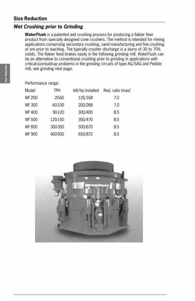
Wet Crushing prior to GrindingWaterFlush is a patented wet crushing process for producing a flakier finerproduct from specially designed cone crushers. The method is intended for miningapplications comprising secondary crushing, sand manufacturing and fine crushingof ore prior to leaching. The typically crusher discharge is a slurry of 30 to 70%solids. The flakier feed brakes easily in the following grinding mill. WaterFlush canbe an alternative to conventional crushing prior to grinding in applications withcritical-size-build-up problems in the grinding circuits of type AG/SAG and Pebblemill, see grinding next page.
Performance range:
Model TPH kW/hp installed Red. ratio (max)
WF 200 20-60 125/168 7.0
WF 300 60-100 200/268 7.0
WF 400 90-120 300/400 8.5
WF 500 120-150 350/470 8.5
WF 800 300-350 500/670 8.5
WF 900 400-500 650/872 8.5
Product Handbook 3:13
Size Reduction
Size
Red
uctio
n
BASICS IN MINERAL PROCESSING
Grinding – IntroductionSize reduction by crushing has a size limitation for the final products. If we requirefurther reduction, say below 5-20mm, we have to use the processes of grindingGrinding is a powdering or pulverizing process using the rock mechanical forcesof impaction, compression, shearing and attrition.The two main purposes for a grinding process are:
• To liberate individual minerals trapped in rock crystals (ores) and thereby openup for a subsequent enrichment in the form of separation.
• To produce fines (or filler) from mineral fractions by increasing the specificsurface.
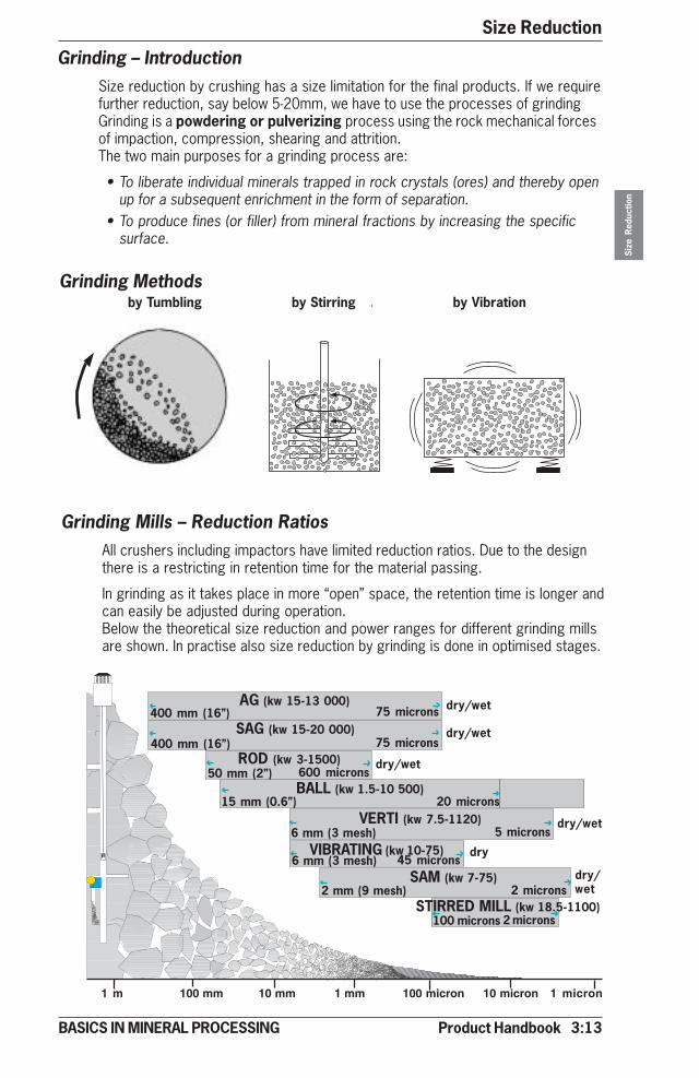
Grinding Methods
Grinding Mills – Reduction RatiosAll crushers including impactors have limited reduction ratios. Due to the designthere is a restricting in retention time for the material passing.
In grinding as it takes place in more “open” space, the retention time is longer andcan easily be adjusted during operation.Below the theoretical size reduction and power ranges for different grinding millsare shown. In practise also size reduction by grinding is done in optimised stages.
1 m 100 mm 10 mm 1 mm 100 micron 10 micron 1 micron
AG (kw 15-13 000)
ROD (kw 3-1500)50 mm (2”) 600 microns
BALL (kw 1.5-10 500)15 mm (0.6”)
VERTI (kw 7.5-1120)6 mm (3 mesh)
VIBRATING (kw 10-75)6 mm (3 mesh) 45 microns
SAM (kw 7-75)2 mm (9 mesh) 2 microns
STIRRED MILL (kw 18.5-1100)100 microns 2 microns
dry/wet
dry/wet
Dry/wet
dry
SAG (kw 15-20 000)400 mm (16”)
400 mm (16”) 75 microns
dry/wet
dry/wet
dry/wet75 microns
20 microns
5 microns
by Tumbling by Stirring by Vibration

3:14 Product Handbook
Size ReductionSi
ze R
educ
tion
BASICS IN MINERAL PROCESSING
Grinding – Tumbling Mills
Autogenous (AG) mill
• Wet or dry• Primary, coarse grinding (up to 400 mm feed size)• Grinding media is grinding feed• High capacity (short retention time)• Sensitive to feed composition (critical size material),
see data sheet 3:34
Semi – Autogenous (SAG) mill
• Wet or dry• Higher capacity than A-G mill grinding• Primary, coarse grinding (up to 400 mm feed size)• Grinding media is grinding feed plus 4-12% ball charge (ball dia.100-125 mm)• High capacity (short retention time)• Less sensitive to feed composition (critical size material), see data sheet 3:34
Rod mill
• Wet only• Coarse grind• Primary mill at plant capacities
of less than 200t/h• Coarse grinding with top size
control without classification• Narrow particle size distribution
• Mostly dry• Coarse grind and high capacity• Special applications• End discharge: finer product• Centre discharge: rapid flow,
less fines• Narrow particle distribution
Overflow End peripheral discharge Center peripheral discharge
Cascade type US European type
Cascade type US European type
Note! No grate discharge
Product Handbook 3:15
Size Reduction
Size
Red
uctio
n
BASICS IN MINERAL PROCESSING
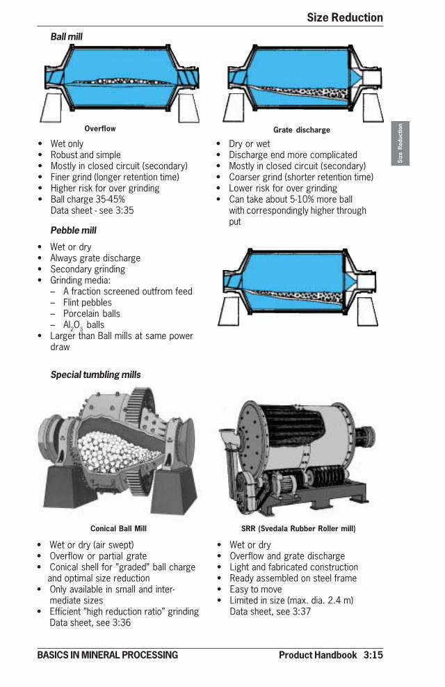
Ball mill
Pebble mill
• Wet or dry• Always grate discharge• Secondary grinding• Grinding media:
– A fraction screened outfrom feed– Flint pebbles– Porcelain balls– Al2O3 balls
• Larger than Ball mills at same powerdraw
Special tumbling mills
Overflow Grate discharge
• Wet only • Dry or wet• Robust and simple • Discharge end more complicated• Mostly in closed circuit (secondary) • Mostly in closed circuit (secondary)• Finer grind (longer retention time) • Coarser grind (shorter retention time)• Higher risk for over grinding • Lower risk for over grinding• Ball charge 35-45% • Can take about 5-10% more ball
Data sheet - see 3:35 with correspondingly higher throughput
• Wet or dry• Overflow and grate discharge• Light and fabricated construction• Ready assembled on steel frame• Easy to move• Limited in size (max. dia. 2.4 m)
Data sheet, see 3:37
• Wet or dry (air swept)• Overflow or partial grate• Conical shell for ”graded” ball charge and optimal size reduction• Only available in small and inter-
mediate sizes• Efficient ”high reduction ratio” grinding
Data sheet, see 3:36
Conical Ball Mill SRR (Svedala Rubber Roller mill)
3:16 Product Handbook
Size ReductionSi
ze R
educ
tion
BASICS IN MINERAL PROCESSING
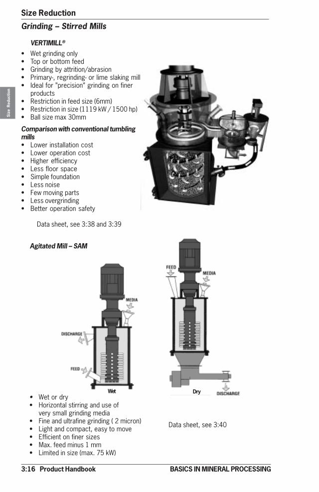
Grinding – Stirred Mills
VERTIMILL®
• Wet grinding only• Top or bottom feed• Grinding by attrition/abrasion• Primary-, regrinding- or lime slaking mill• Ideal for ”precision” grinding on finer
products• Restriction in feed size (6mm)• Restriction in size (1119 kW / 1500 hp)• Ball size max 30mm
Comparison with conventional tumblingmills• Lower installation cost• Lower operation cost• Higher efficiency• Less floor space• Simple foundation• Less noise• Few moving parts• Less overgrinding• Better operation safety
Agitated Mill – SAM
• Wet or dry• Horizontal stirring and use of
very small grinding media• Fine and ultrafine grinding ( 2 micron)• Light and compact, easy to move• Efficient on finer sizes• Max. feed minus 1 mm• Limited in size (max. 75 kW)
Data sheet, see 3:38 and 3:39
Data sheet, see 3:40
Wet Dry

Product Handbook 3:17
Size Reduction
Size
Red
uctio
n
BASICS IN MINERAL PROCESSING
Stirred Media Grinding Mills
Grinding – Vibrating Mills
Vibrating ball mill
• Wet or dry
• Impact, shearing and attrition
• Open or closed circuit
• Short retention time - lessovergrinding
• Feed size, minus 5 mm
• Limited in size
(2x37 kW, 2x50 hp)
• High noise level
• Low cost, simple installations
Data sheet, see 3:44
Wet Grinding Only
• Open or closed circuit
• Feed size 100 micron and below
• Product size down to 2 micron
• Grinding media:
Silica pebbles and sand, 1 to 9 mm,for coarser grinds down to 10micron
Silica sand, 0.5 to 1 mm, for finergrinds below 10 micron
Synthetic media with above sizeranges can be used in place ofsilica sand
Three machine sizes available, withinstalled powers of 185 kW, 355 kW,and 1100 kW
Data sheet, see 3:43
3:18 Product Handbook
Size ReductionSi
ze R
educ
tion
BASICS IN MINERAL PROCESSING
Secondary Ball Mills Secondary Pebble Mills
Primary Ball Mills
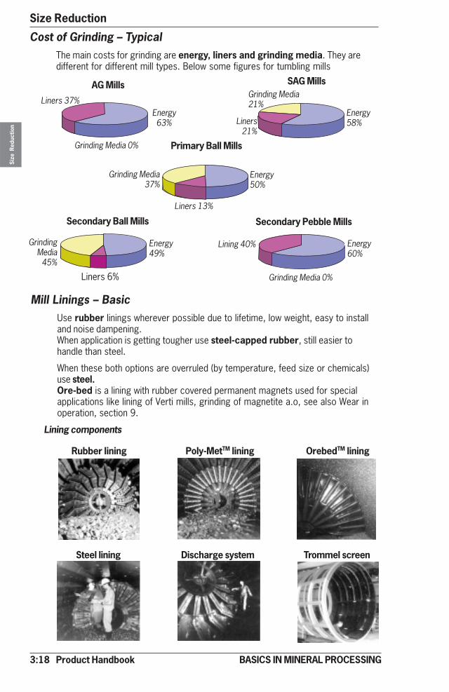
SAG MillsAG Mills
Liners 37%
Grinding Media 0%
Liners21%
Energy58%
Grinding Media21%
Liners 13%
Energy50%
Grinding Media37%
Liners 6%
Energy49%
GrindingMedia45%
Lining 40% Energy60%
Grinding Media 0%
Energy63%
Cost of Grinding – TypicalThe main costs for grinding are energy, liners and grinding media. They aredifferent for different mill types. Below some figures for tumbling mills
Mill Linings – BasicUse rubber linings wherever possible due to lifetime, low weight, easy to installand noise dampening.When application is getting tougher use steel-capped rubber, still easier tohandle than steel.
When these both options are overruled (by temperature, feed size or chemicals)use steel.Ore-bed is a lining with rubber covered permanent magnets used for specialapplications like lining of Verti mills, grinding of magnetite a.o, see also Wear inoperation, section 9.
Lining components
Rubber lining Poly-MetTM lining OrebedTM lining
Steel lining Discharge system Trommel screen
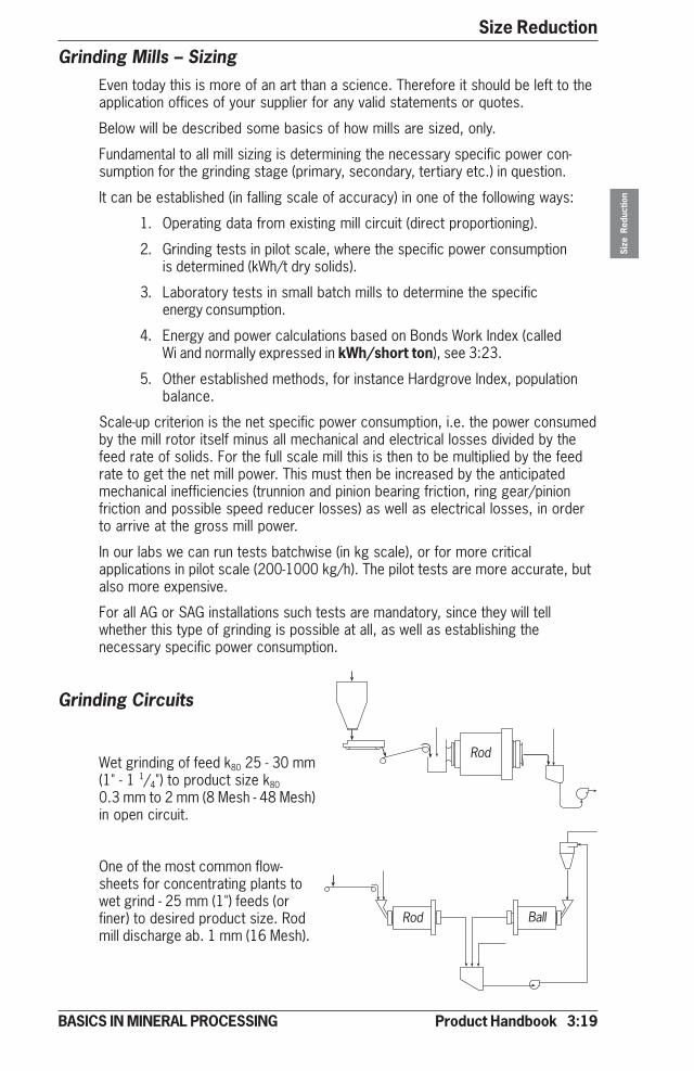
Product Handbook 3:19
Size Reduction
Size
Red
uctio
n
BASICS IN MINERAL PROCESSING
Grinding Mills – SizingEven today this is more of an art than a science. Therefore it should be left to theapplication offices of your supplier for any valid statements or quotes.
Below will be described some basics of how mills are sized, only.
Fundamental to all mill sizing is determining the necessary specific power con-sumption for the grinding stage (primary, secondary, tertiary etc.) in question.
It can be established (in falling scale of accuracy) in one of the following ways:
1. Operating data from existing mill circuit (direct proportioning).
2. Grinding tests in pilot scale, where the specific power consumptionis determined (kWh/t dry solids).
3. Laboratory tests in small batch mills to determine the specificenergy consumption.
4. Energy and power calculations based on Bonds Work Index (calledWi and normally expressed in kWh/short ton), see 3:23.
5. Other established methods, for instance Hardgrove Index, populationbalance.
Scale-up criterion is the net specific power consumption, i.e. the power consumedby the mill rotor itself minus all mechanical and electrical losses divided by thefeed rate of solids. For the full scale mill this is then to be multiplied by the feedrate to get the net mill power. This must then be increased by the anticipatedmechanical inefficiencies (trunnion and pinion bearing friction, ring gear/pinionfriction and possible speed reducer losses) as well as electrical losses, in orderto arrive at the gross mill power.
In our labs we can run tests batchwise (in kg scale), or for more criticalapplications in pilot scale (200-1000 kg/h). The pilot tests are more accurate, butalso more expensive.
For all AG or SAG installations such tests are mandatory, since they will tellwhether this type of grinding is possible at all, as well as establishing thenecessary specific power consumption.
Grinding Circuits
Wet grinding of feed k80 25 - 30 mm(1" - 1 1/4") to product size k80
0.3 mm to 2 mm (8 Mesh - 48 Mesh)in open circuit.
One of the most common flow-sheets for concentrating plants towet grind - 25 mm (1") feeds (orfiner) to desired product size. Rodmill discharge ab. 1 mm (16 Mesh).
Rod
Rod Ball
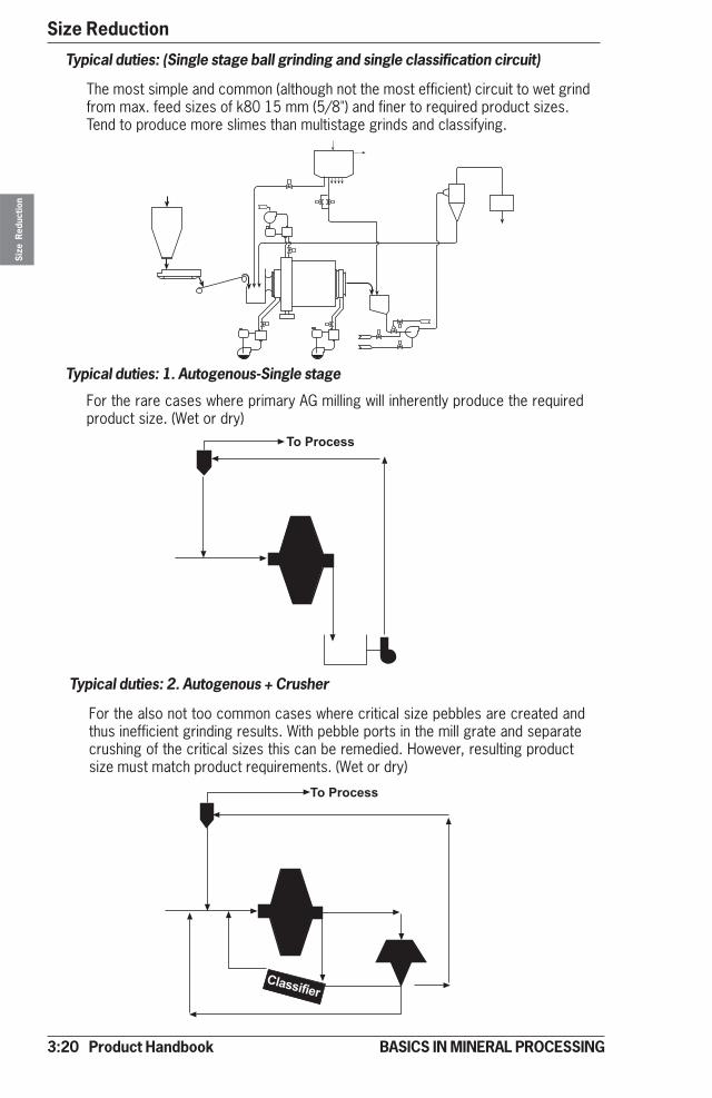
3:20 Product Handbook
Size ReductionSi
ze R
educ
tion
BASICS IN MINERAL PROCESSING
����������
Typical duties: (Single stage ball grinding and single classification circuit)
The most simple and common (although not the most efficient) circuit to wet grindfrom max. feed sizes of k80 15 mm (5/8") and finer to required product sizes.Tend to produce more slimes than multistage grinds and classifying.
Typical duties: 1. Autogenous-Single stage
For the rare cases where primary AG milling will inherently produce the requiredproduct size. (Wet or dry)
Typical duties: 2. Autogenous + Crusher
For the also not too common cases where critical size pebbles are created andthus inefficient grinding results. With pebble ports in the mill grate and separatecrushing of the critical sizes this can be remedied. However, resulting productsize must match product requirements. (Wet or dry)
���� ���
����������
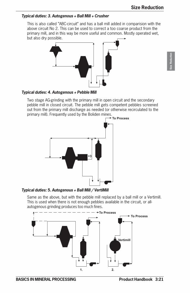
Product Handbook 3:21
Size Reduction
Size
Red
uctio
n
BASICS IN MINERAL PROCESSING
����������
��
Typical duties: 3. Autogenous + Ball Mill + Crusher
This is also called ”ABC-circuit” and has a ball mill added in comparision with theabove circuit No 2. This can be used to correct a too coarse product from theprimary mill, and in this way be more useful and common. Mostly operated wet,but also dry possible.
Typical duties: 4. Autogenous + Pebble Mill
Two stage AG-grinding with the primary mill in open circuit and the secondarypebble mill in closed circuit. The pebble mill gets competent pebbles screenedout from the primary mill discharge as needed (or otherwise recirculated to theprimary mill). Frequently used by the Boliden mines.
Typical duties: 5. Autogenous + Ball Mill / VertiMill
Same as the above, but with the pebble mill replaced by a ball mill or a Vertimill.This is used when there is not enough pebbles available in the circuit, or all-autogenous grinding produces too much fines.
��������������������
�������
�� ��
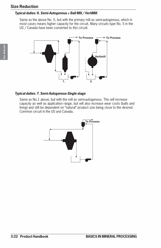
3:22 Product Handbook
Size ReductionSi
ze R
educ
tion
BASICS IN MINERAL PROCESSING
����������
Typical duties: 7. Semi-Autogenous-Single stage
Same as No.1 above, but with the mill as semi-autogenous. This will increasecapacity as well as application range, but will also increase wear costs (balls andlining) and still be dependent on ”natural” product size being close to the desired.Common circuit in the US and Canada.
Typical duties: 6. Semi-Autogenous + Ball Mill / VertiMill
Same as the above No. 5, but with the primary mill as semi-autogenous, which inmost cases means higher capacity for the circuit. Many circuits type No. 5 in theUS / Canada have been converted to this circuit.
���������� ����������
�������
�� ��

Product Handbook 3:23
Size Reduction
Size
Red
uctio
n
BASICS IN MINERAL PROCESSING
Typical duties: 9. Closed circuit with Cyclone
For wet circuits with fine or veryfine product size and more stringentlimits for product top size.
VERTIMILL® Circuits
Typical duties: 8. Closed circuit with Integral Classifier
For wet circuits with not too fine desired product and/or not stringent limits oncoarse end oversize of the product. Max. feed size - 6 mm (1/4")
������������
�����
���������
�� ������
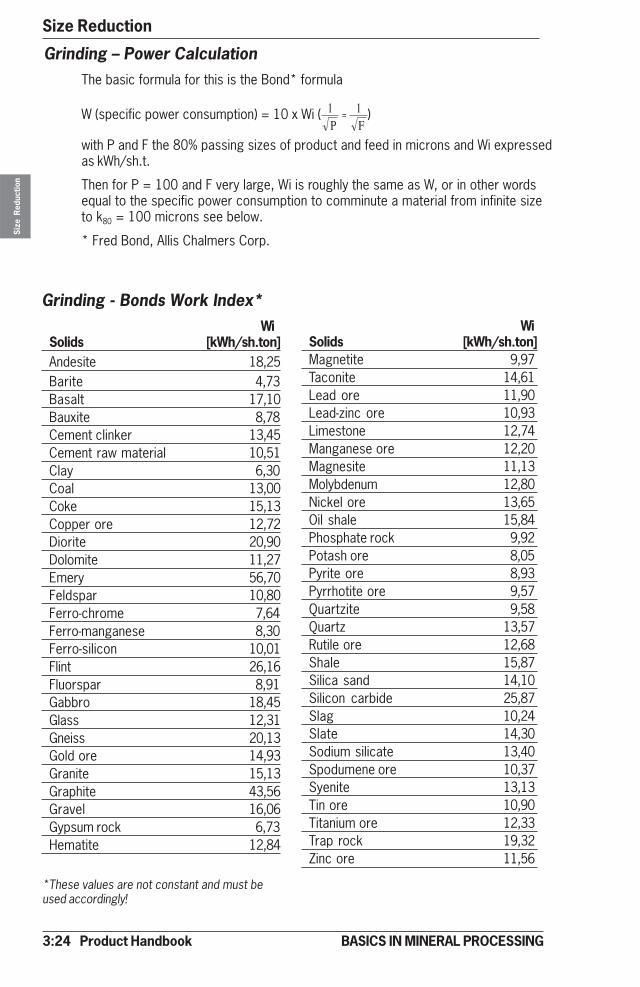
3:24 Product Handbook
Size ReductionSi
ze R
educ
tion
BASICS IN MINERAL PROCESSING
Grinding – Power CalculationThe basic formula for this is the Bond* formula
W (specific power consumption) = 10 x Wi ( )
with P and F the 80% passing sizes of product and feed in microns and Wi expressedas kWh/sh.t.
Then for P = 100 and F very large, Wi is roughly the same as W, or in other wordsequal to the specific power consumption to comminute a material from infinite sizeto k80 = 100 microns see below.
* Fred Bond, Allis Chalmers Corp.
Grinding - Bonds Work Index*Wi
Solids [kWh/sh.ton]Andesite 18,25Barite 4,73Basalt 17,10Bauxite 8,78Cement clinker 13,45Cement raw material 10,51Clay 6,30Coal 13,00Coke 15,13Copper ore 12,72Diorite 20,90Dolomite 11,27Emery 56,70Feldspar 10,80Ferro-chrome 7,64Ferro-manganese 8,30Ferro-silicon 10,01Flint 26,16Fluorspar 8,91Gabbro 18,45Glass 12,31Gneiss 20,13Gold ore 14,93Granite 15,13Graphite 43,56Gravel 16,06Gypsum rock 6,73Hematite 12,84
WiSolids [kWh/sh.ton]Magnetite 9,97Taconite 14,61Lead ore 11,90Lead-zinc ore 10,93Limestone 12,74Manganese ore 12,20Magnesite 11,13Molybdenum 12,80Nickel ore 13,65Oil shale 15,84Phosphate rock 9,92Potash ore 8,05Pyrite ore 8,93Pyrrhotite ore 9,57Quartzite 9,58Quartz 13,57Rutile ore 12,68Shale 15,87Silica sand 14,10Silicon carbide 25,87Slag 10,24Slate 14,30Sodium silicate 13,40Spodumene ore 10,37Syenite 13,13Tin ore 10,90Titanium ore 12,33Trap rock 19,32Zinc ore 11,56
*These values are not constant and must beused accordingly!
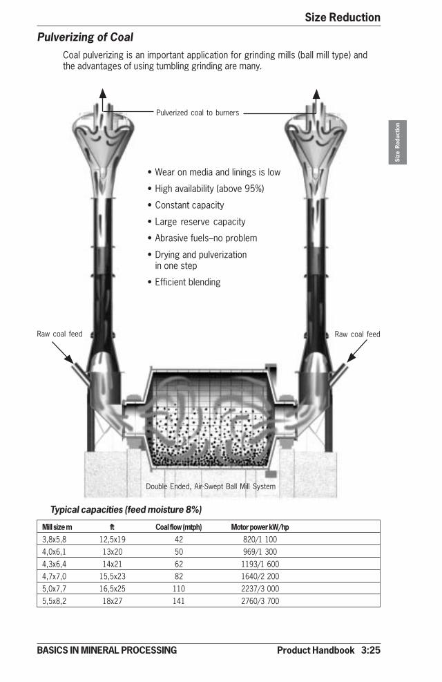
Product Handbook 3:25
Size Reduction
Size
Red
uctio
n
BASICS IN MINERAL PROCESSING
Pulverizing of CoalCoal pulverizing is an important application for grinding mills (ball mill type) andthe advantages of using tumbling grinding are many.
Pulverized coal to burners
• Wear on media and linings is low
• High availability (above 95%)
• Constant capacity
• Large reserve capacity
• Abrasive fuels–no problem
• Drying and pulverizationin one step
• Efficient blending
Raw coal feedRaw coal feed
Typical capacities (feed moisture 8%)
Mill size m ft Coal flow (mtph) Motor power kW/hp3,8x5,8 12,5x19 42 820/1 1004,0x6,1 13x20 50 969/1 3004,3x6,4 14x21 62 1193/1 6004,7x7,0 15,5x23 82 1640/2 2005,0x7,7 16,5x25 110 2237/3 0005,5x8,2 18x27 141 2760/3 700
Double Ended, Air-Swept Ball Mill System
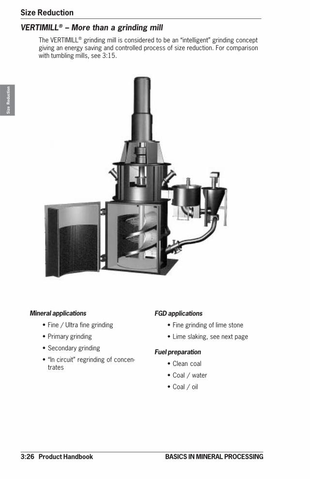
3:26 Product Handbook
Size ReductionSi
ze R
educ
tion
BASICS IN MINERAL PROCESSING
VERTIMILL® – More than a grinding millThe VERTIMILL® grinding mill is considered to be an “intelligent” grinding conceptgiving an energy saving and controlled process of size reduction. For comparisonwith tumbling mills, see 3:15.
Mineral applications
• Fine / Ultra fine grinding
• Primary grinding
• Secondary grinding
• “In circuit” regrinding of concen-trates
FGD applications
• Fine grinding of lime stone
• Lime slaking, see next page
Fuel preparation
• Clean coal
• Coal / water
• Coal / oil

Product Handbook 3:27
Size Reduction
Size
Red
uctio
n
BASICS IN MINERAL PROCESSING
� � �
�
�
� � �
Grinding vs Enrichment and UpgradingIn the size reduction stages of grinding we are also creating the conditions for thefollowing process stages of enrichment and upgrading.
From the picture below we can see the effect of “under- and over grinding”.
The lost performance in separation, sedimentation and dewatering due to “mis-grinding” represents a major problem for many operations, eroding the processeconomy.
“un-liberated”particles reportingto concentrate
“un-liberated”particles reportingto tailings
higher settling velocity lower “capillary forces”
“total liberation”slime losses to tailings lower settling velocity higher “capillary forces”
“under grinding”(too coarse grind)
“optimal grinding”(normal grind)
“over grinding”(too fine grind)
Separation
Concentrate Tailings Sedimentation Dewatering
VERTIMILL® as Lime SlakerThe VERTIMILL® is an excellent lime slaker producing an optimal product in asimple one-step operation.
Typical operation conditions:
Material Pebble lime with approximately 5 % grit
Feed size minus 25mm (1”)
Product size 90-95% passing 45 micron (325 Mesh)
Percent solids (product) 20-26%
Temperature inside mill (product) 50-70 °C (130-160°F)
Capacities vs Mill sizesMtph CaO Stph CaO Mill unit Motor kW Motorhp
1,4 1,5 VTM-10-LS 7,5 10
2,7 3,0 VTM-20-LS 14,9 20
3,7 4,1 VTM-30-LS 22,4 30
5,3 5,8 VTM-50-LS 37,3 50
6,6 7,3 VTM-100-LS 44,7 60
12,0 13,2 VTM-150-LS 74,6 100
13,9 15,3 VTM-200-LS 111,9 150
18,7 20,6 VTM-300-LS 149,1 200
30,0 33,0 VTM-400-LS 223,7 300
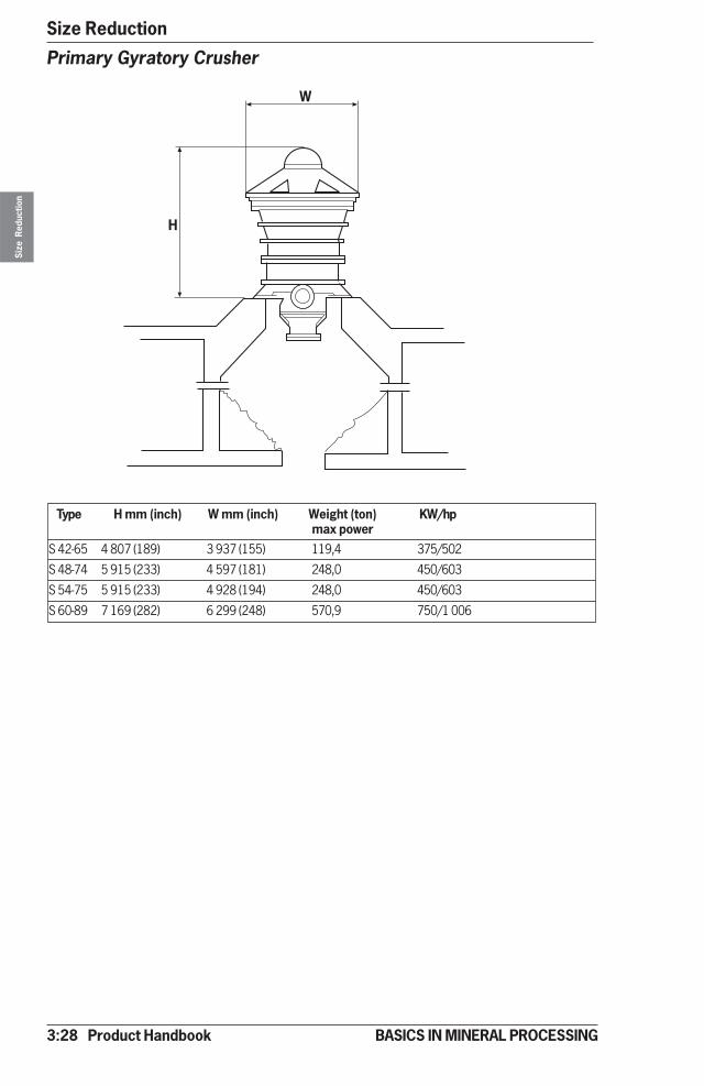
3:28 Product Handbook
Size ReductionSi
ze R
educ
tion
BASICS IN MINERAL PROCESSING
Type H mm (inch) W mm (inch) Weight (ton) KW/hpmax power
S 42-65 4 807 (189) 3 937 (155) 119,4 375/502
S 48-74 5 915 (233) 4 597 (181) 248,0 450/603
S 54-75 5 915 (233) 4 928 (194) 248,0 450/603
S 60-89 7 169 (282) 6 299 (248) 570,9 750/1 006
Primary Gyratory Crusher
�
�
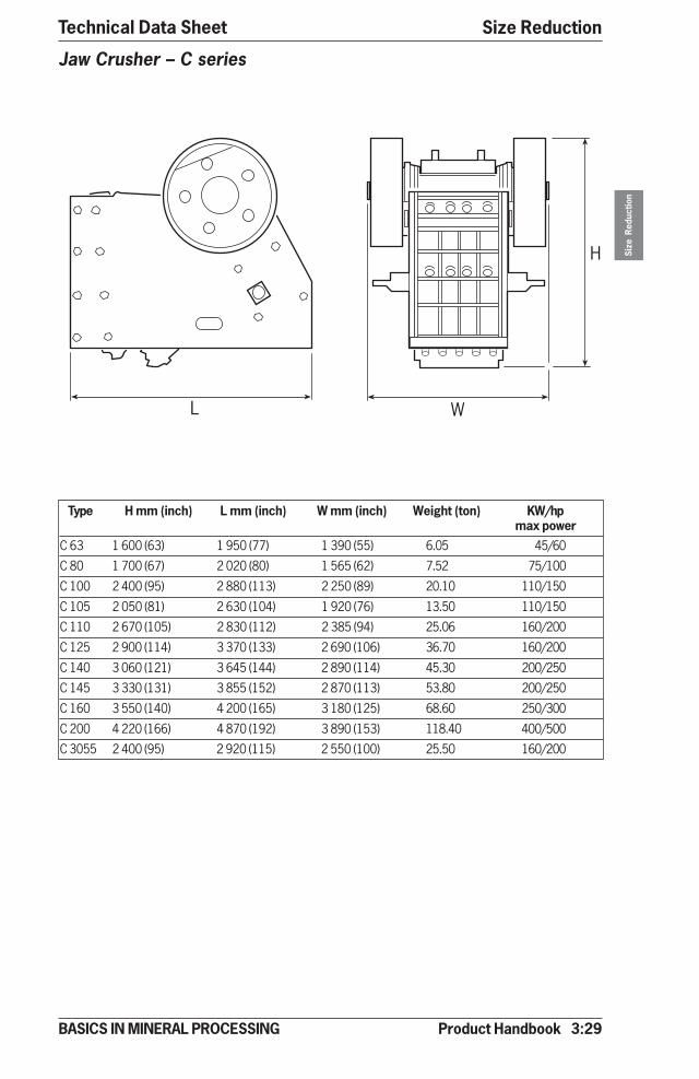
Product Handbook 3:29
Size Reduction
Size
Red
uctio
n
BASICS IN MINERAL PROCESSING
Technical Data Sheet
Type H mm (inch) L mm (inch) W mm (inch) Weight (ton) KW/hpmax power
C 63 1 600 (63) 1 950 (77) 1 390 (55) 6.05 45/60
C 80 1 700 (67) 2 020 (80) 1 565 (62) 7.52 75/100
C 100 2 400 (95) 2 880 (113) 2 250 (89) 20.10 110/150
C 105 2 050 (81) 2 630 (104) 1 920 (76) 13.50 110/150
C 110 2 670 (105) 2 830 (112) 2 385 (94) 25.06 160/200
C 125 2 900 (114) 3 370 (133) 2 690 (106) 36.70 160/200
C 140 3 060 (121) 3 645 (144) 2 890 (114) 45.30 200/250
C 145 3 330 (131) 3 855 (152) 2 870 (113) 53.80 200/250
C 160 3 550 (140) 4 200 (165) 3 180 (125) 68.60 250/300
C 200 4 220 (166) 4 870 (192) 3 890 (153) 118.40 400/500
C 3055 2 400 (95) 2 920 (115) 2 550 (100) 25.50 160/200
Jaw Crusher – C series
� �
�
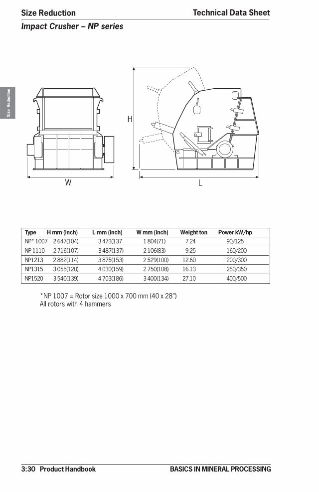
3:30 Product Handbook
Size ReductionSi
ze R
educ
tion
BASICS IN MINERAL PROCESSING
Type H mm (inch) L mm (inch) W mm (inch) Weight ton Power kW/hpNP* 1007 2 647(104) 3 473(137 1 804(71) 7.24 90/125
NP 1110 2 716(107) 3 487(137) 2 106(83) 9.25 160/200
NP1213 2 882(114) 3 875(153) 2 529(100) 12.60 200/300
NP1315 3 055(120) 4 030(159) 2 750(108) 16.13 250/350
NP1520 3 540(139) 4 703(186) 3 400(134) 27.10 400/500
Impact Crusher – NP series
�
�
�
Technical Data Sheet
*NP 1007 = Rotor size 1000 x 700 mm (40 x 28”)All rotors with 4 hammers

Product Handbook 3:31
Size Reduction
Size
Red
uctio
n
BASICS IN MINERAL PROCESSING
Technical Data Sheet
Type H mm (inch) W/L mm (inch) Weight ton Max. power kW/hpGP100S 2 328 (92) 1 300 (51) 7.5 90/125
GP200S 2 461 (97) 1 745 (69) 10.6 160/250
GP300S 2 546 (100) 1 858 (73) 16.0 250/350
GP500S 3 227 (127) 2 300 (91) 32.0 315/400
Cone Crusher – GPS series
�
�
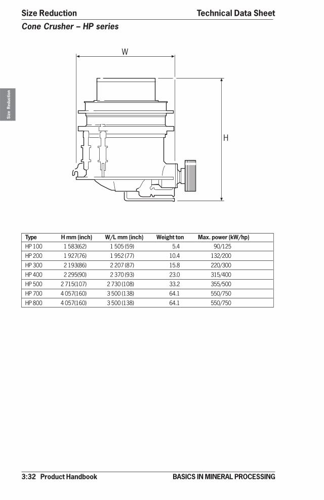
3:32 Product Handbook
Size ReductionSi
ze R
educ
tion
BASICS IN MINERAL PROCESSING
Cone Crusher – HP series
Type H mm (inch) W/L mm (inch) Weight ton Max. power (kW/hp)HP 100 1 583(62) 1 505 (59) 5.4 90/125
HP 200 1 927(76) 1 952 (77) 10.4 132/200
HP 300 2 193(86) 2 207 (87) 15.8 220/300
HP 400 2 295(90) 2 370 (93) 23.0 315/400
HP 500 2 715(107) 2 730 (108) 33.2 355/500
HP 700 4 057(160) 3 500 (138) 64.1 550/750
HP 800 4 057(160) 3 500 (138) 64.1 550/750
Technical Data Sheet
�
�
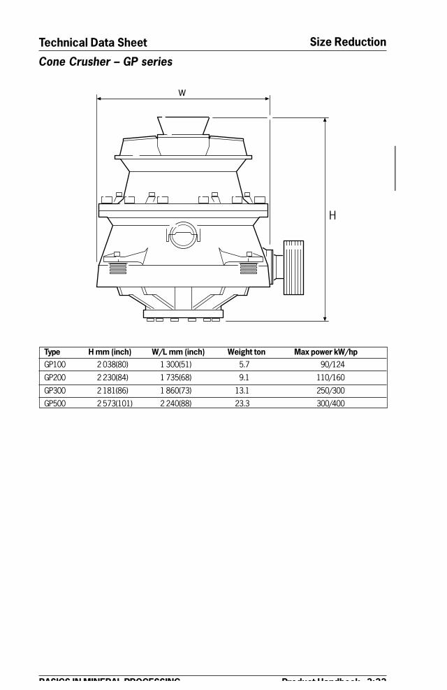
Product Handbook 3:33
Size Reduction
BASICS IN MINERAL PROCESSING
Technical Data Sheet
Type H mm (inch) W/L mm (inch) Weight ton Max power kW/hpGP100 2 038(80) 1 300(51) 5.7 90/124
GP200 2 230(84) 1 735(68) 9.1 110/160
GP300 2 181(86) 1 860(73) 13.1 250/300
GP500 2 573(101) 2 240(88) 23.3 300/400
Cone Crusher – GP series
�
�

3:34 Product Handbook
Size ReductionSi
ze R
educ
tion
BASICS IN MINERAL PROCESSING
Type H mm (inch) W/L mm (inch) Weight ton Max.power kW/hpMP800 4 622 (182) 3 500 (138) 120 600/800
MP1000 4 540 (179) 3 950 (156) 150 745/1000
Cone Crusher – MP seriesTechnical Data Sheet
�
�

Product Handbook 3:35
Size Reduction
Size
Red
uctio
n
BASICS IN MINERAL PROCESSING
Technical Data Sheet
Type H mm (inch) W/L mm (inch) Weight ton Max power kW/hpB 5100 1 705 (67) 1 435 (57) 2,5 55/75
B 6100 2 211 (56) 1 770 (45) 4,8 110/150
B 7100 2 549 (100) 2 004 (79) 6,5 185/250
B 8100 2 713 (107) 2 220 (87) 9,0 300/400
B 9100 2 813 (111) 2 434 (96) 9,3 600/800
XD 120 4 211 (166) 3 110 (122) 23,3 800/1075
Vertical Shaft Impactor (VSI)
�
�
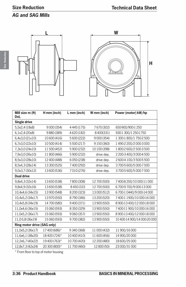
3:36 Product Handbook
Size ReductionSi
ze R
educ
tion
BASICS IN MINERAL PROCESSING
AG and SAG Mills
Mill size m (ft) H mm (inch) L mm (inch) W mm (inch) Power (motor) kW/hpDxLSingle drive
5,5x2,4 (18x8) 9 000 (354) 4 445 (175) 7 670 (302) 650-900/900-1 250
6,1x2,4 (20x8) 9 880 (389) 4 620 (182) 8 400(331) 930-1 300/1 250-1750
6,4x3,0 (21x10) 10 600 (416) 5 600 (222) 9 000 (354) 1 300-1 800/1 750-2 500
6,7x3,0 (22x10) 10 500 (414) 5 500 (217) 9 150 (360) 1 490-2 200/2 000-3 000
7,3x3,0 (24x10) 11 500 (452) 5 900 (232) 10 100 (398) 1 800-2 600/2 500-3 500
7,9x3,0 (26x10) 11 800 (466) 5 900 (232) drive dep. 2 200-3 400/3 000-4 500
8,5x3,0 (28x10) 12 400 (488) 6 050 (238) drive dep. 2 600-4 100/3 500-5 500
8,5x4,3 (28x14) 13 300 (525) 7 400 (292) drive dep. 3 700-5 600/5 000-7 500
9,0x3,7 (30x12) 13 600 (536) 7 010 (276) drive dep. 3 700-5 600/5 000-7 500
Dual drive
9,8x4,3 (32x14) 13 650 (538) 7 800 (308) 12 700 (500) 7 400-8 200/10 000-11 000
9,8x4,9 (32x16) 13 650 (538) 8 450 (333 12 700 (500) 6 700-9 700/9 000-13 000
10,4x4,6 (34x15) 13 900 (548) 8 200 (323) 13 000 (512) 6 700-1 0440/9 000-14 000
10,4x5,2 (34x17) 13 970 (550) 8 790 (346) 13 200 (520) 7 400-1 1900/10 000-16 000
10,4x5,8 (34x19) 14 700 (580) 9 400 (371) 13 900 (550) 8 900-13 400/12 000-18 000
11,0x4,6 (36x15) 15 060 (593) 8 350 (329) 13 900 (550) 7 400-11 900/10 000-16 000
11,0x5,2 (36x17) 15 060 (593) 9 060 (357) 13 900 (550) 8 900-13 400/12 000-18 000
11,0-5,8 (36x19) 15 060 (593) 9 700 (382) 13 900 (550) 10 400-14 900/14 000-20 000
Ring motor drive (SAG only)
11,0x5,2 (36x17) 17 400 (686)* 9 340 (368) 11 000 (432) 11 900/16 000
11,6x6,1 (38x20) 18 400 (724)* 10 400 (410) 11 600 (456) 14 900/20 000
12,2x6,7 (40x22) 19 400 (763)* 10 700 (420) 12 200 (480) 18 600/25 000
12,8x7,3 (42x24) 20 300 (800)* 11 700 (460) 12 800 (50) 23 000/31 000
* From floor to top of motor housing
� �
�
Technical Data Sheet

Product Handbook 3:37
Size Reduction
Size
Red
uctio
n
BASICS IN MINERAL PROCESSING
Technical Data Sheet
Ball Mill
Mill size m (ft) H mm (inch) L mm (inch) W mm (inch) Power motorDxL kW/hp
2,4x3,0 (8x10) 4 670 (184) 4 480 (176) 3 860 (152) 224/300
2,4x 3,7 (8x12) 4 670 (184) 5 050 (199) 3 860 (152) 260/350
2,4x4,3 (8x14) 4 670 (184) 5 660 (223) 3 960 (156) 298/400
2,7x3,7 (9x12) 5 180 (204) 5 050 (199) 3 960 (156) 336/450
2,7x 4,3 (9x14) 5 330 (210) 5 660 (223) 4 270 (168) 373/500
2,9x4,6 (9,5x15) 5 530 (218) 6 170 (243) 4 370 (172) 447/600
3,0x4,6 (10x15) 6 170 (243) 6 240 (246) 5 020 (198) 522/700
3,2x4,6 (10,5x15) 6 500 (256) 6 320 (249) 5 390 (212) 597/800
3,2x 5,2 (10,5x17) 6 500 (256) 6 930 (273) 5 390 (212) 671/900
3,4x5,2 (11x17) 6 190 (244) 6 830 (269) 5 200 (205) 746/1 000
3,5x5,5 (11,5x1) 6 380 (251) 7 140 (281) 5 360 (211) 983/1 250
4,0x5,2 (13x17) 7 160 (282) 7 030 (277) 6 200 (244) 1 119/1 500
4,0x5,8 (13x19) 7 160 (282) 7 600 (299) 6 200 (244) 1 305/1 750
4,3x5,5 (14x18) 7 620 (300) 7 510 (296) 6 600 (260) 1 491/2 000
4,3x 6,0 (14x20) 7 620 (300) 8 120 (320) 6 600 (260) 1 529/2 250
4,6x5,8 (15x19) 8 180 (322) 7 950 (313) 7 110 (280) 1 864/2 500
4,6x6,4 (15,5x21) 8 690 (342) 8 560 (337) 7 650 (301) 2 237/3 000
5,0x6,4 (16,5x21) 8 840 (348) 8 890 (350) 7 820 (308) 2 610/3 500
5,0x7,3 (16,5x24) 8 840 (348) 9 800 (386) 7 820 (308) 2 983/4 000
5,0x8,2 (16,5x27) 9 530 (375) 10 500(414) 8 480 (334) 3 356/4 500
5,0x9,1 (16,5x30) 9 600 (378) 11 650(459) 8 560 (337) 3 728/5 000
5,0x10,0 (16,5x33) 9 600 (378) 12 570(495) 8 560 (337) 4 101/5 500
5,5x8,8 (18x29) 1 010 (398) 11 600(457) 9 040 (356) 4 474/6 000
5,5x9,6 (18x31,5) 1 090 (430) 12 570(495) 9 980 (389) 4 847/6 500
5,5x10,2 (18x33) 1 160 (456) 13 180(519) 10 440(411) 5 220/7 000
6,0x9,6 (20x31,5) 1 230 (484) 12 700(500) 10 800(425) 5 966/8 000
6,0x10,2 (20x33,5) 1 230 (484) 13 300(524) 10 800(425) 6711/9 000
� �
�
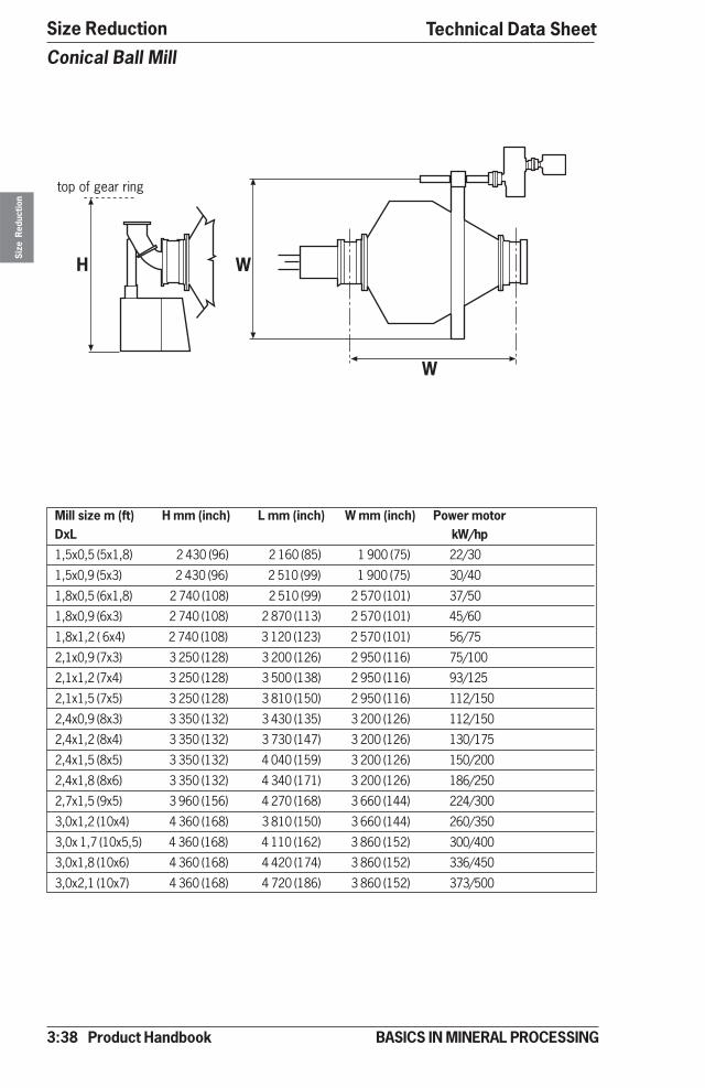
3:38 Product Handbook
Size ReductionSi
ze R
educ
tion
BASICS IN MINERAL PROCESSING
Conical Ball Mill
Mill size m (ft) H mm (inch) L mm (inch) W mm (inch) Power motorDxL kW/hp
1,5x0,5 (5x1,8) 2 430 (96) 2 160 (85) 1 900 (75) 22/30
1,5x0,9 (5x3) 2 430 (96) 2 510 (99) 1 900 (75) 30/40
1,8x0,5 (6x1,8) 2 740 (108) 2 510 (99) 2 570 (101) 37/50
1,8x0,9 (6x3) 2 740 (108) 2 870 (113) 2 570 (101) 45/60
1,8x1,2 ( 6x4) 2 740 (108) 3 120 (123) 2 570 (101) 56/75
2,1x0,9 (7x3) 3 250 (128) 3 200 (126) 2 950 (116) 75/100
2,1x1,2 (7x4) 3 250 (128) 3 500 (138) 2 950 (116) 93/125
2,1x1,5 (7x5) 3 250 (128) 3 810 (150) 2 950 (116) 112/150
2,4x0,9 (8x3) 3 350 (132) 3 430 (135) 3 200 (126) 112/150
2,4x1,2 (8x4) 3 350 (132) 3 730 (147) 3 200 (126) 130/175
2,4x1,5 (8x5) 3 350 (132) 4 040 (159) 3 200 (126) 150/200
2,4x1,8 (8x6) 3 350 (132) 4 340 (171) 3 200 (126) 186/250
2,7x1,5 (9x5) 3 960 (156) 4 270 (168) 3 660 (144) 224/300
3,0x1,2 (10x4) 4 360 (168) 3 810 (150) 3 660 (144) 260/350
3,0x 1,7 (10x5,5) 4 360 (168) 4 110 (162) 3 860 (152) 300/400
3,0x1,8 (10x6) 4 360 (168) 4 420 (174) 3 860 (152) 336/450
3,0x2,1 (10x7) 4 360 (168) 4 720 (186) 3 860 (152) 373/500
� �
�
�������� � ��
Technical Data Sheet
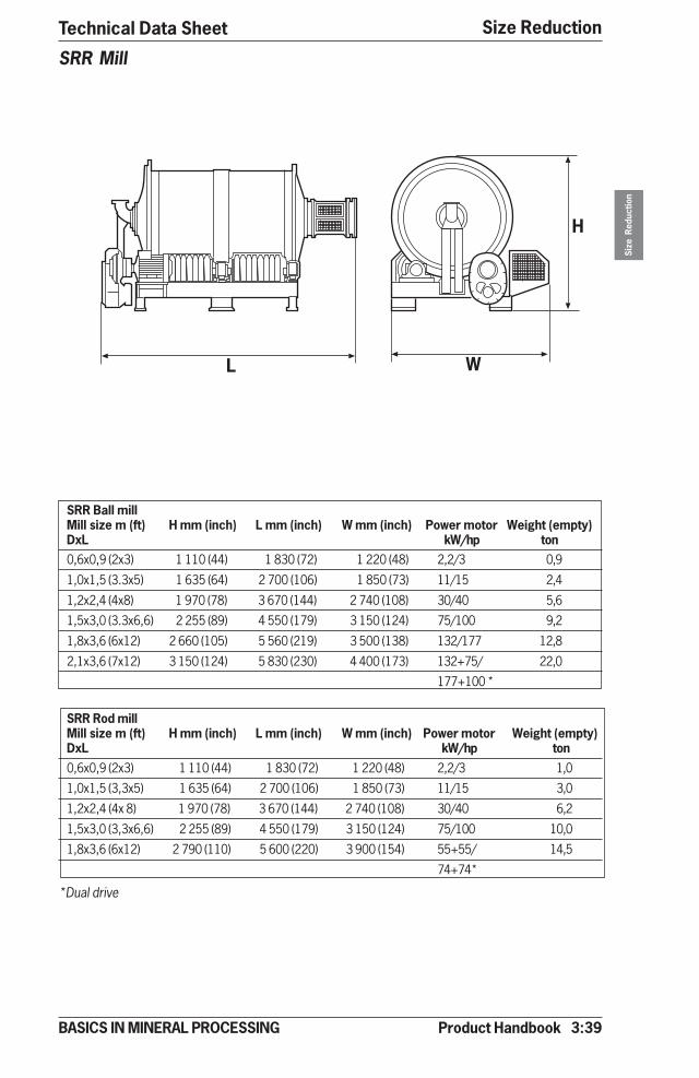
Product Handbook 3:39
Size Reduction
Size
Red
uctio
n
BASICS IN MINERAL PROCESSING
Technical Data Sheet
SRR Mill
SRR Ball millMill size m (ft) H mm (inch) L mm (inch) W mm (inch) Power motor Weight (empty)DxL kW/hp ton0,6x0,9 (2x3) 1 110 (44) 1 830 (72) 1 220 (48) 2,2/3 0,9
1,0x1,5 (3.3x5) 1 635 (64) 2 700 (106) 1 850 (73) 11/15 2,4
1,2x2,4 (4x8) 1 970 (78) 3 670 (144) 2 740 (108) 30/40 5,6
1,5x3,0 (3.3x6,6) 2 255 (89) 4 550 (179) 3 150 (124) 75/100 9,2
1,8x3,6 (6x12) 2 660 (105) 5 560 (219) 3 500 (138) 132/177 12,8
2,1x3,6 (7x12) 3 150 (124) 5 830 (230) 4 400 (173) 132+75/ 22,0
177+100 *
SRR Rod millMill size m (ft) H mm (inch) L mm (inch) W mm (inch) Power motor Weight (empty)DxL kW/hp ton0,6x0,9 (2x3) 1 110 (44) 1 830 (72) 1 220 (48) 2,2/3 1,0
1,0x1,5 (3,3x5) 1 635 (64) 2 700 (106) 1 850 (73) 11/15 3,0
1,2x2,4 (4x 8) 1 970 (78) 3 670 (144) 2 740 (108) 30/40 6,2
1,5x3,0 (3,3x6,6) 2 255 (89) 4 550 (179) 3 150 (124) 75/100 10,0
1,8x3,6 (6x12) 2 790 (110) 5 600 (220) 3 900 (154) 55+55/ 14,5
74+74*
�
�
�
*Dual drive
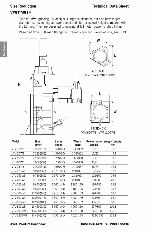
3:40 Product Handbook
Size ReductionSi
ze R
educ
tion
BASICS IN MINERAL PROCESSING
� �
�
�������������������������������������
�
�
�
�
���������������� ����������������!�����
Model H mm L mm W mm Power motor Weight (empty)(inch) (inch) (inch) kW/hp ton
VTM-15-WB 7 060 (278) 1 520 (60) 1 320 (52) 11/15 5,5
VTM-20-WB 7 180 (283) 1 520 (60) 1 320 (52) 15/20 5,9
VTM-40-WB 7 460 (294) 1 780 (70) 1 520 (60) 3040 8,2
VTM-60-WB 7 600 (299) 1 780 (70) 1 520 (60) 45/60 8,8
VTM-75-WB 7 900 (311) 1 960 (77) 1 700 (67) 56/75 12,5
VTM-125-WB 9 270 (365) 2 670 (105) 2 310 (91) 93/125 17,9
VTM-150-WB 9 780 (385) 2 670 (105) 2 310 (91) 112/150 19,6
VTM-200-WB 9 780 (385) 2 670 (105) 2 310 (91) 150/200 20,5
VTM-250-WB 9 650 (380) 3 660 (144) 3 180 (125) 186/250 33,8
VTM-300-WB 9 650 (380) 3 660 (144) 3 180 (125) 224/300 35,7
VTM-400-WB 11 320 (446) 3 910 (154) 3 380 (133) 298/400 52,7
VTM-500-WB 12 070 (475) 3 860 (152) 3 780 (149) 373/500 66,1
VTM-650-WB 12 270 (483) 3 250 (128) 3 860 (152) 485/650 82,6
VTM-800-WB 13 460 (530) 3 560 (140) 4 060 (160) 597/800 100,4
VTM-1000-WB 13 460 (530) 3 660 (144) 4 270 (168) 746/1 000 116,1
VTM-1250-WB 13 460 (530) 4 090 (161) 4 520 (178) 932/1 250 125,4
VERTIMILL®
Type WB (Wet grinding – B design) is larger in diameter, but also have largerdiameter, screw turning at lower speed and shorter overall height compared withthe LS type. They are designed to operate at full motor power. Orebed lining.
Regarding type LS (Lime Slaking) for size reduction and slaking of lime, see 3:39
SECTION C-CVTM-15-WB – VTM-500-WB
SECTION C-CVTM-650-WB – VTM-1250-WB
Technical Data Sheet

Product Handbook 3:41
Size Reduction
Size
Red
uctio
n
BASICS IN MINERAL PROCESSING
Technical Data Sheet
Model H mm (inch) L mm (inch) W mm (inch) Power motor Weight (empty)kW/hp ton
VTM-20-LS 7 060 (278) 1 520 (60) 1 320 (52) 15/20 5,5
VTM-30-LS 7 180 (283) 1 520 (60) 1 320 (52) 22/30 5,9
VTM-50-LS 7 460 (294) 1 780 (70) 1 520 (60) 37/50 8,2
VTM-100-LS 7 900 (311) 1 960 (77) 1 700 (67) 45/60 8,8
VTM-150-LS 8 740 (344) 2 670 (105) 2 310 (91) 75/100 12,5
VTM-200-LS 9 780 (385) 2 670 (105) 2 310 (91) 112/150 17,9
VTM-300-LS 10 160 (400) 3 660 (144) 3 180 (125) 150/200 19,6
VTM-400-LS 11 320 (446) 3 910 (154) 3 380 (133) 224/300 50,0
VERTIMILL®
Type LS (Lime Slaking) for size reduction and slaking of limeRegarding type WB (Wide body) for grinding operations only, see: 3:38
�
��
������������
� �
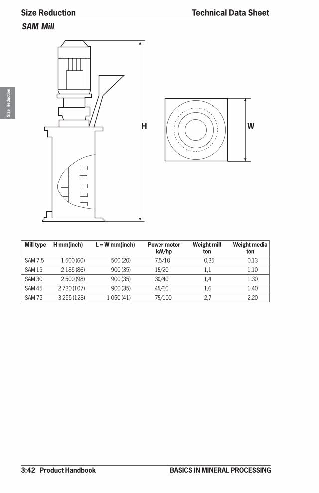
3:42 Product Handbook
Size ReductionSi
ze R
educ
tion
BASICS IN MINERAL PROCESSING
Mill type H mm(inch) L = W mm(inch) Power motor Weight mill Weight mediakW/hp ton ton
SAM 7.5 1 500 (60) 500 (20) 7.5/10 0,35 0,13
SAM 15 2 185 (86) 900 (35) 15/20 1,1 1,10
SAM 30 2 500 (98) 900 (35) 30/40 1,4 1,30
SAM 45 2 730 (107) 900 (35) 45/60 1,6 1,40
SAM 75 3 255 (128) 1 050 (41) 75/100 2,7 2,20
SAM Mill
��
Technical Data Sheet
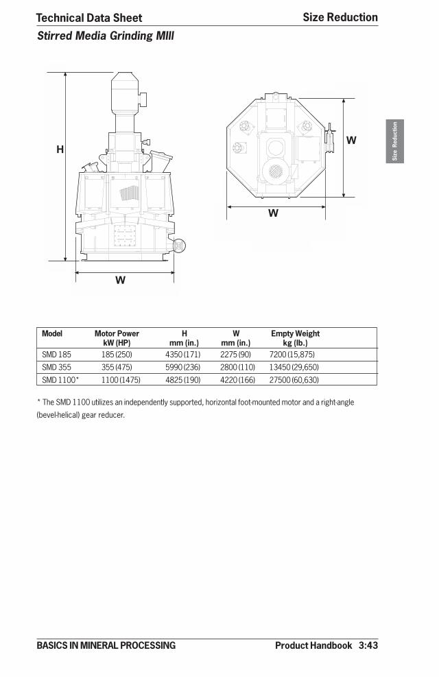
Product Handbook 3:43
Size Reduction
Size
Red
uctio
n
BASICS IN MINERAL PROCESSING
Stirred Media Grinding MIll
Model Motor Power H W Empty WeightkW (HP) mm (in.) mm (in.) kg (lb.)
SMD 185 185 (250) 4350 (171) 2275 (90) 7200 (15,875)
SMD 355 355 (475) 5990 (236) 2800 (110) 13450 (29,650)
SMD 1100* 1100 (1475) 4825 (190) 4220 (166) 27500 (60,630)
* The SMD 1100 utilizes an independently supported, horizontal foot-mounted motor and a right-angle
(bevel-helical) gear reducer.
�
�
�
��
�
Technical Data Sheet
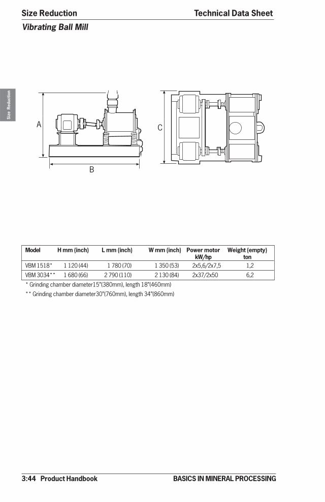
3:44 Product Handbook
Size ReductionSi
ze R
educ
tion
BASICS IN MINERAL PROCESSING
Model H mm (inch) L mm (inch) W mm (inch) Power motor Weight (empty)kW/hp ton
VBM 1518* 1 120 (44) 1 780 (70) 1 350 (53) 2x5,6/2x7,5 1,2
VBM 3034** 1 680 (66) 2 790 (110) 2 130 (84) 2x37/2x50 6,2
* Grinding chamber diameter15”(380mm), length 18”(460mm)
** Grinding chamber diameter30”(760mm), length 34”(860mm)
Vibrating Ball Mill
"
�
�
Technical Data Sheet
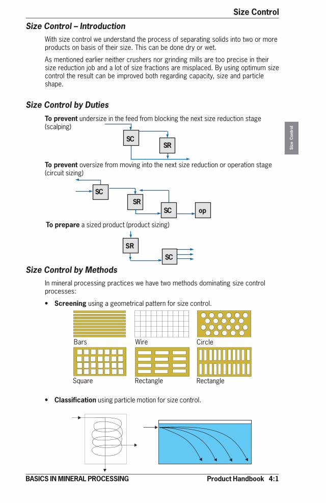
Product Handbook 4:1
Size Control
Size
Con
trol
BASICS IN MINERAL PROCESSING
Size Control – IntroductionWith size control we understand the process of separating solids into two or moreproducts on basis of their size. This can be done dry or wet.
As mentioned earlier neither crushers nor grinding mills are too precise in theirsize reduction job and a lot of size fractions are misplaced. By using optimum sizecontrol the result can be improved both regarding capacity, size and particleshape.
Size Control by Duties
• Classification using particle motion for size control.
Size Control by MethodsIn mineral processing practices we have two methods dominating size controlprocesses:
• Screening using a geometrical pattern for size control.
To prevent undersize in the feed from blocking the next size reduction stage(scalping)
To prevent oversize from moving into the next size reduction or operation stage(circuit sizing)
To prepare a sized product (product sizing)
SCSR
SC op
SCSR
SR
SC
Bars Wire Circle
Square Rectangle Rectangle
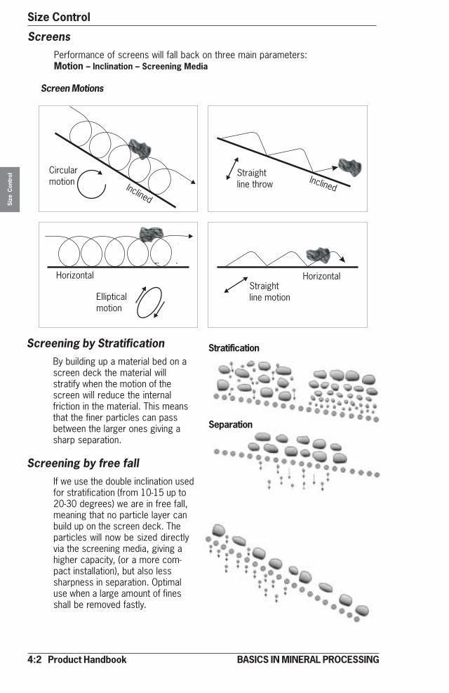
4:2 Product Handbook
Size ControlSi
ze C
ontr
ol
BASICS IN MINERAL PROCESSING
ScreensPerformance of screens will fall back on three main parameters:Motion – Inclination – Screening Media
Screen Motions
Screening by StratificationBy building up a material bed on ascreen deck the material willstratify when the motion of thescreen will reduce the internalfriction in the material. This meansthat the finer particles can passbetween the larger ones giving asharp separation.
Screening by free fallIf we use the double inclination usedfor stratification (from 10-15 up to20-30 degrees) we are in free fall,meaning that no particle layer canbuild up on the screen deck. Theparticles will now be sized directlyvia the screening media, giving ahigher capacity, (or a more com-pact installation), but also lesssharpness in separation. Optimaluse when a large amount of finesshall be removed fastly.
Stratification
Separation
Inclined
Circularmotion
Horizontal
Ellipticalmotion
Straightline motion
Horizontal
Straightline throw Inclined
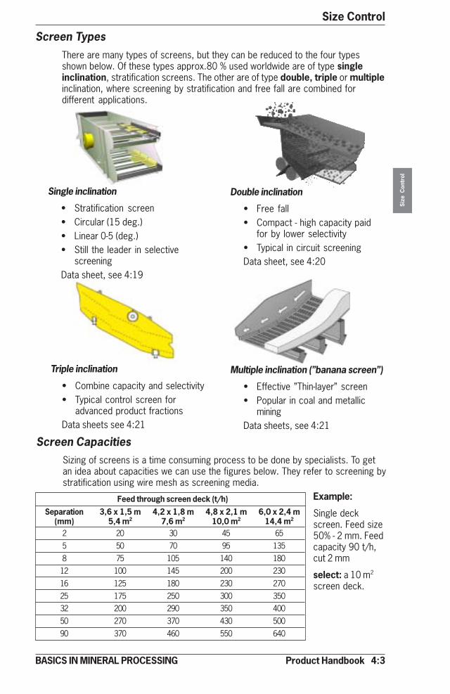
Product Handbook 4:3
Size Control
Size
Con
trol
BASICS IN MINERAL PROCESSING
Single inclination
• Stratification screen• Circular (15 deg.)• Linear 0-5 (deg.)• Still the leader in selective
screeningData sheet, see 4:19
Triple inclination
• Combine capacity and selectivity• Typical control screen for
advanced product fractionsData sheets see 4:21
Multiple inclination (’’banana screen’’)
• Effective ”Thin-layer” screen• Popular in coal and metallic
miningData sheets, see 4:21
Double inclination
• Free fall• Compact - high capacity paid
for by lower selectivity• Typical in circuit screeningData sheet, see 4:20
Screen TypesThere are many types of screens, but they can be reduced to the four typesshown below. Of these types approx.80 % used worldwide are of type singleinclination, stratification screens. The other are of type double, triple or multipleinclination, where screening by stratification and free fall are combined fordifferent applications.
Screen CapacitiesSizing of screens is a time consuming process to be done by specialists. To getan idea about capacities we can use the figures below. They refer to screening bystratification using wire mesh as screening media.
Feed through screen deck (t/h)Separation 3,6 x 1,5 m 4,2 x 1,8 m 4,8 x 2,1 m 6,0 x 2,4 m
(mm) 5,4 m2 7,6 m2 10,0 m2 14,4 m2
2 20 30 45 655 50 70 95 1358 75 105 140 18012 100 145 200 23016 125 180 230 27025 175 250 300 35032 200 290 350 40050 270 370 430 50090 370 460 550 640
Example:
Single deckscreen. Feed size50% - 2 mm. Feedcapacity 90 t/h,cut 2 mm
select: a 10 m2
screen deck.
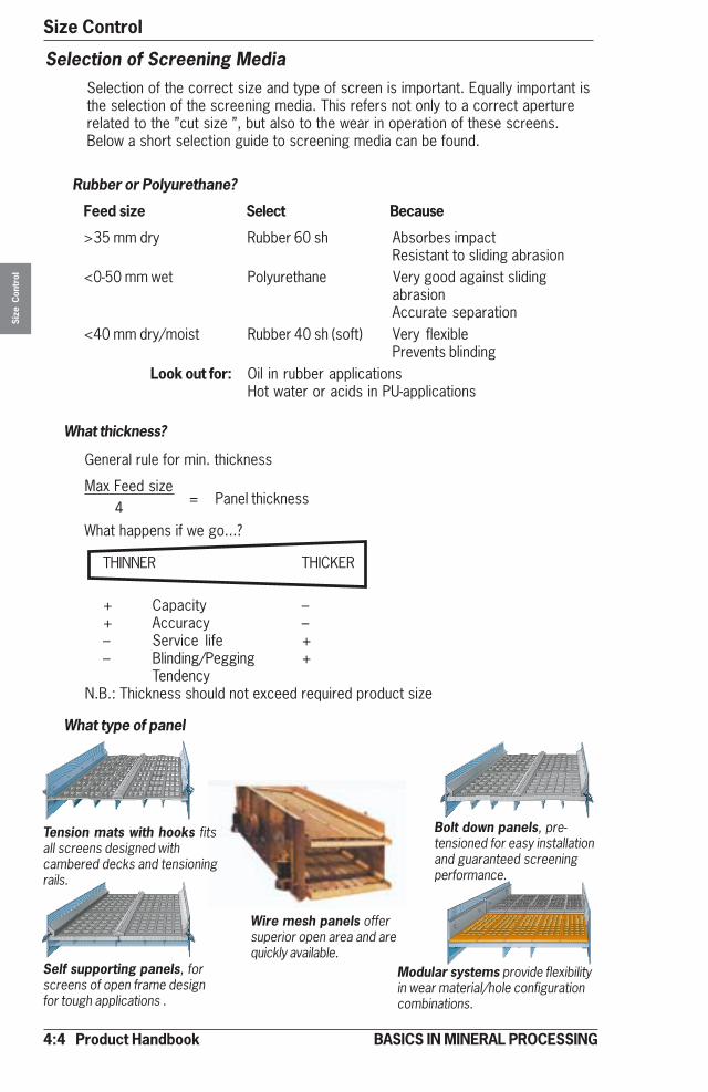
4:4 Product Handbook
Size ControlSi
ze C
ontr
ol
BASICS IN MINERAL PROCESSING
Rubber or Polyurethane?
Feed size Select Because
>35 mm dry Rubber 60 sh Absorbes impactResistant to sliding abrasion
<0-50 mm wet Polyurethane Very good against slidingabrasionAccurate separation
<40 mm dry/moist Rubber 40 sh (soft) Very flexiblePrevents blinding
Look out for: Oil in rubber applicationsHot water or acids in PU-applications
Selection of Screening MediaSelection of the correct size and type of screen is important. Equally important isthe selection of the screening media. This refers not only to a correct aperturerelated to the ”cut size ”, but also to the wear in operation of these screens.Below a short selection guide to screening media can be found.
THINNER THICKER
+ Capacity –+ Accuracy –– Service life +– Blinding/Pegging +
TendencyN.B.: Thickness should not exceed required product size
What happens if we go...?
General rule for min. thickness
Max Feed size= Panel thickness
4
What thickness?
What type of panel
Tension mats with hooks fitsall screens designed withcambered decks and tensioningrails.
Bolt down panels, pre-tensioned for easy installationand guaranteed screeningperformance.
Self supporting panels, forscreens of open frame designfor tough applications .
Modular systems provide flexibilityin wear material/hole configurationcombinations.
Wire mesh panels offersuperior open area and arequickly available.
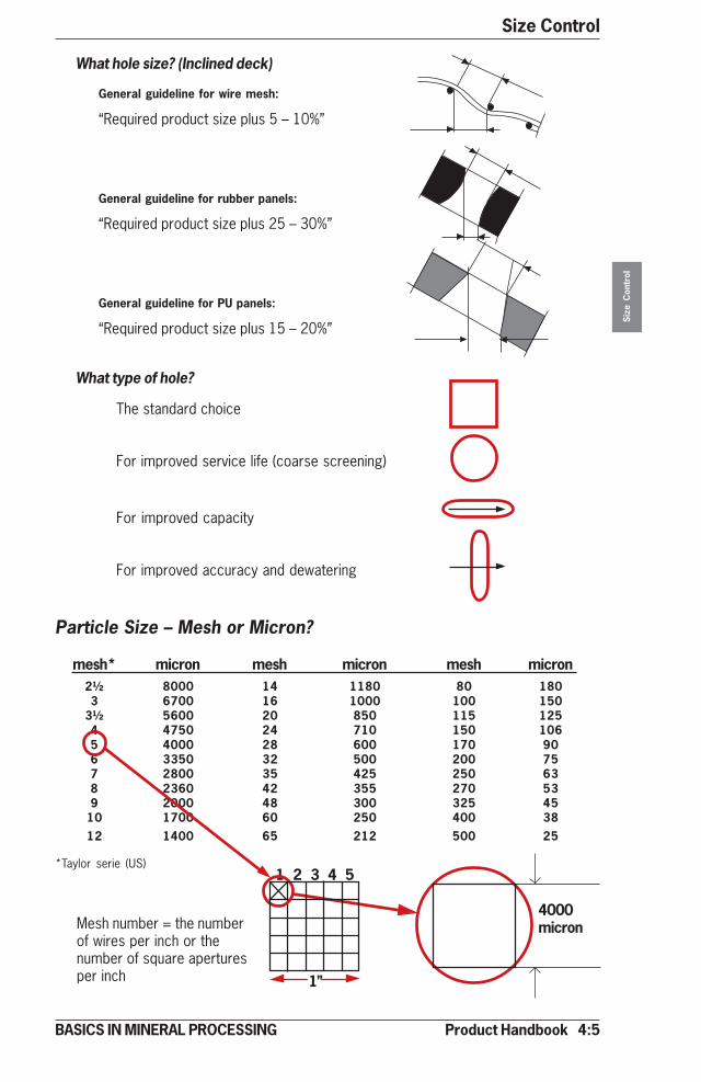
Product Handbook 4:5
Size Control
Size
Con
trol
BASICS IN MINERAL PROCESSING
General guideline for wire mesh:
“Required product size plus 5 – 10%”
General guideline for rubber panels:
“Required product size plus 25 – 30%”
General guideline for PU panels:
“Required product size plus 15 – 20%”
What hole size? (Inclined deck)
The standard choice
For improved service life (coarse screening)
For improved capacity
For improved accuracy and dewatering
What type of hole?
mesh* micron mesh micron mesh micron2½ 8000 14 1180 80 1803 6700 16 1000 100 150
3½ 5600 20 850 115 1254 4750 24 710 150 1065 4000 28 600 170 906 3350 32 500 200 757 2800 35 425 250 638 2360 42 355 270 539 2000 48 300 325 45
10 1700 60 250 400 3812 1400 65 212 500 25
*Taylor serie (US)
Mesh number = the numberof wires per inch or thenumber of square aperturesper inch
4000micron
1 2 3 4 5
1”
Particle Size – Mesh or Micron?

4:6 Product Handbook
Size ControlSi
ze C
ontr
ol
BASICS IN MINERAL PROCESSING
Classification – IntroductionFor size control of particles finer than 1 mm, we are moving out of the practicalrange of conventional screens.
Classification is the process of separating particles by size into two or moreproducts according to their behaviour in air or water (liquids).
Classification methods
• Wet classification with Hydrocyclones using separation by centrifugal forcecovering the size range of 100 –10 micron (typical)
• Wet classification with Spiral classifiers using separation by gravity coveringthe size range of 100- 1000 micron (typical)
• Dry classification using separation by centrifugal force covering the range of150 –5 micron (typical).
Wet classification – fundamentals
If a particle has no interference from other particles it moves faster than aparticle surrounded by other particles due to increased density and viscosity ofthe slurry.This is called free and hindered movement and is valid both for gravity andcentrifugal classification.
��
��
Coarse particles movefaster than fine particles atequal density
High density particles movefaster than low density parti-cles at equal size
�
Free movement Hindered movement
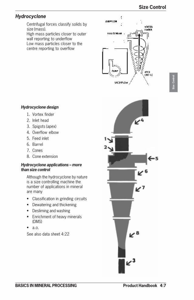
Product Handbook 4:7
Size Control
Size
Con
trol
BASICS IN MINERAL PROCESSING
HydrocycloneCentrifugal forces classify solids bysize (mass).High mass particles closer to outerwall reporting to underflowLow mass particles closer to thecentre reporting to overflow
Hydrocyclone design
1. Vortex finder2. Inlet head3. Spigots (apex)4. Overflow elbow5. Feed inlet6. Barrel7. Cones8. Cone extension
Hydrocyclone applications – morethan size control
Although the hydrocyclone by natureis a size controlling machine thenumber of applications in mineralare many
• Classification in grinding circuits• Dewatering and thickening• Desliming and washing• Enrichment of heavy minerals
(DMS)• a.o.
See also data sheet 4:22
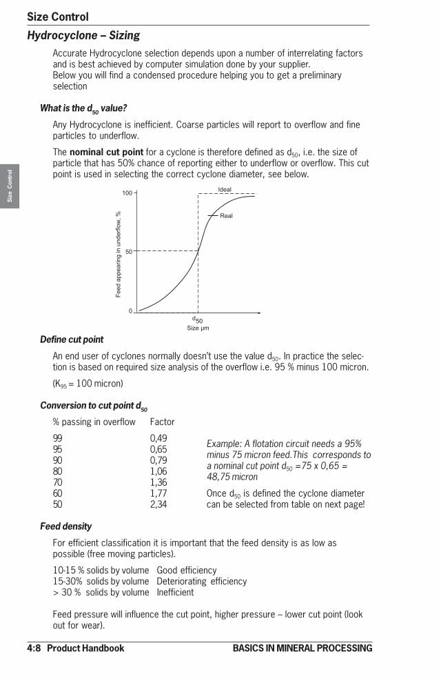
4:8 Product Handbook
Size ControlSi
ze C
ontr
ol
BASICS IN MINERAL PROCESSING
���
��
����
����
���
�� �
�� ����������
�����
����
��� �
�� �
Hydrocyclone – SizingAccurate Hydrocyclone selection depends upon a number of interrelating factorsand is best achieved by computer simulation done by your supplier.Below you will find a condensed procedure helping you to get a preliminaryselection
What is the d50 value?
Any Hydrocyclone is inefficient. Coarse particles will report to overflow and fineparticles to underflow.
The nominal cut point for a cyclone is therefore defined as d50, i.e. the size ofparticle that has 50% chance of reporting either to underflow or overflow. This cutpoint is used in selecting the correct cyclone diameter, see below.
Define cut point
An end user of cyclones normally doesn’t use the value d50. In practice the selec-tion is based on required size analysis of the overflow i.e. 95 % minus 100 micron.
(K95 = 100 micron)
Conversion to cut point d50
% passing in overflow Factor
99 0,4995 0,6590 0,7980 1,0670 1,3660 1,7750 2,34
Feed density
For efficient classification it is important that the feed density is as low aspossible (free moving particles).
10-15 % solids by volume Good efficiency15-30% solids by volume Deteriorating efficiency> 30 % solids by volume Inefficient
Feed pressure will influence the cut point, higher pressure – lower cut point (lookout for wear).
Example: A flotation circuit needs a 95%minus 75 micron feed.This corresponds toa nominal cut point d50 =75 x 0,65 =48,75 micron
Once d50 is defined the cyclone diametercan be selected from table on next page!

Product Handbook 4:9
Size Control
Size
Con
trol
BASICS IN MINERAL PROCESSING
����
���
��
�
���������� �������
�����
�����
�
!� "� ���
�#�
$��
%��
!$�
���
#��
"��
&��
����
�$��
�!
�& %$%'
�$"! '% &� &� ��� ��& ��� �$�
�"
& ���%
$� $% $� $# $& %� %% %'
�����
����
���
��
�
!� "� ���
�#�
$��
%��
!$�
���
#��
"��
&��
����
�$��
�!��
���������� �������
�(�)*+�
������ ���%,-
Select hydrocyclone diameter
Once d50 is defined the hydrocyclone diameter can be selected from the followingtable: Example above = 48 micron = cyclone dia 250 mm (10”).
Select quantity of hydrocyclones
The volumetric capacity of a cyclone depends upon its diameter. A larger cyclonewill handle a larger capacity. Once the required diameter has been defined thenthe number of units needed to handle the given feed flow can be determined fromthe following table. Example above: 250 mm dia. cyclone = flow rate 100 m3/h/unit.
1.6 3 4 6.5 10 14 16.5 20 24 30 36 40 48 dia inch
48
1.6 3 4 6.5 10 14 16.5 20 24 30 36 40 48 55 dia inch
(44 000)
(4 400)
(440)
(44)
d 50 (
mic
rons
)

4:10 Product Handbook
Size ControlSi
ze C
ontr
ol
BASICS IN MINERAL PROCESSING
Spiral ClassifierBy combining a gravity settler of rectangular section with a sloped transportspiral for the sediment - we have got a spiral classifier.
Spiral Classifier – Nomenclature
SC 90 ST-2 means 90 cm spiral diameter, straight tank, two pitches.
Spiral Classifier – Design
The design of a spiral classifier is simple and robust with few moving parts. Areliable machine for tough classification duties in the 100-1000 micron range.
1. Sedimentation pool2. Transportation spiral3. Drive for spiral4. Overflow weir5. Spiral lift mechanism
Spiral Classifier design features:
• Replaceable wear shoes,
• Submerged bearing for spiral
• Tank options and adjustable weir for full flexibility in pool area and classifica-tion cut point (cp)
Straight Modified Full flarecp 1000-200�m cp 400- 100 �m cp 200-75 �m
Spiral Classifier-applications
As for the hydrocyclone this size control machine has many practical applicationsin mineral processing• Closed circuit grinding (primary classification with cyclone as secondary)• Dewatering• Sand recovery• De-sliming• Heavy media densifying
1. 4.
5.
3.
2.
Adjustable weir
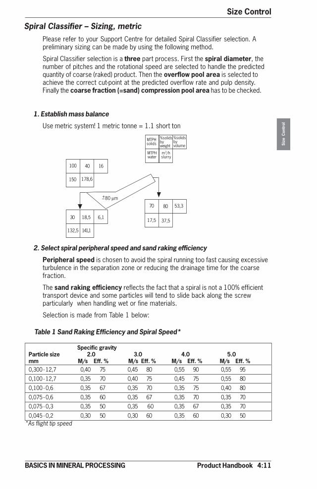
Product Handbook 4:11
Size Control
Size
Con
trol
BASICS IN MINERAL PROCESSING
Spiral Classifier – Sizing, metricPlease refer to your Support Centre for detailed Spiral Classifier selection. Apreliminary sizing can be made by using the following method.
Spiral Classifier selection is a three part process. First the spiral diameter, thenumber of pitches and the rotational speed are selected to handle the predictedquantity of coarse (raked) product. Then the overflow pool area is selected toachieve the correct cut-point at the predicted overflow rate and pulp density.Finally the coarse fraction (=sand) compression pool area has to be checked.
1. Establish mass balance
Use metric system! 1 metric tonne = 1.1 short ton
2. Select spiral peripheral speed and sand raking efficiency
Peripheral speed is chosen to avoid the spiral running too fast causing excessiveturbulence in the separation zone or reducing the drainage time for the coarsefraction.
The sand raking efficiency reflects the fact that a spiral is not a 100% efficienttransport device and some particles will tend to slide back along the screwparticularly when handling wet or fine materials.
Selection is made from Table 1 below:
+80 µm–
100 40 16
150 178,6
30 18,5 6,1
132,5 141,1
70 80 53,3
17,5 37,5
MTPHsolids
%solidsbyweight
MTPHwater
m3/hslurry
%solidsbyvolume
Specific gravityParticle size 2.0 3.0 4.0 5.0mm M/s Eff. % M/s Eff. % M/s Eff. % M/s Eff. %0,300 - 12,7 0,40 75 0,45 80 0,55 90 0,55 95
0,100 - 12,7 0,35 70 0,40 75 0,45 75 0,55 80
0,100 - 0,6 0,35 67 0,35 70 0,35 75 0,40 80
0,075 - 0,6 0,35 60 0,35 67 0,35 70 0,35 70
0,075 - 0,3 0,35 50 0,35 60 0,35 67 0,35 70
0,045 - 0,2 0,30 50 0,30 60 0,35 60 0,30 50*As flight tip speed
Table 1 Sand Raking Efficiency and Spiral Speed*

4:12 Product Handbook
Size ControlSi
ze C
ontr
ol
BASICS IN MINERAL PROCESSING
Spiral speed, rpm
Ø cm 3 4 5 6 7 8 9 10 11 12 13 15 16 2030 SP 0,6 0,6
DP SP=Single Pitch 1,2 1,940 SP DP= Double Pitch 0,6 1,2
DP 1,2 1,960 SP 4,3 5,0 5,6 5,6 6,8 7,4 8,1 8,7
DP 8,3 9,4 10,6 10,6 13,0 14,1 15,5 16,775 SP 5,6 6,8 7,4 8,1 8,7 9,3 9,9 10,5
DP 10,6 13,0 14,1 15,3 16,5 17,7 18,9 20,090 SP 9,3 11,2 13,0 14,9 15,5 17,4 19,2
DP 17,7 21,2 24,8 28,3 29,5 33,0 36,5120 SP 18,6 22,3 27,3 31,0 34,1
DP 35,4 42,4 51,9 58,9 64,8150 SP 27,3 35,4 43,4 50,9
DP 51,9 67,2 82,5 96,7200 SP 52,1 68,9 81,9
DP 99,0 130,8 156,6
Table 3 Peripheral Speed (m/s)
Spiral speed, RPM
Ø cm 3 4 5 6 7 8 9 10 11 12 13 14 15 16 200 0,24 0,3240 0,21 0,3260 0,25 0,28 0,32 0,35 0,38 0,42 0,48 0,5175 0,24 0,28 0,32 0,36 0,40 0,44 0,48 0,52 0,2490 0,24 0,28 0,34 0,38 0,43 0,48 0,53120 0,25 0,32 0,38 0,45 0,51150 0,24 0,32 0,40 0,48200 0,31 0,43 0,53
5. Equivalent Particle Size
Pool areas are calculated assuming a particle SG of 2.65. If the actual figure issomething different a correction has to be made. Multiply with the factor√ (SG - 1 / 1.65 (Stokes Law).
For example an 80 µm particle of SG 3.2 has a correction factor of √ (3.2 - 1) / 1.65 = 1.15 so the equivalent particle size is 80 x 1.15=92 µm.
PITCH
3. Calculate ‘corrected’ Rake Capacity
Corrected rake Capacity = Rake Capacity (m3/h)
Spiral Efficiency
Table 2 Rake Capacity (m³/h)
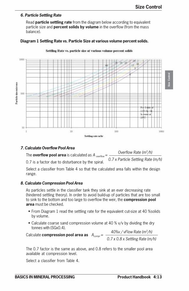
Product Handbook 4:13
Size Control
Size
Con
trol
BASICS IN MINERAL PROCESSING
6. Particle Settling Rate
Read particle settling rate from the diagram below according to equivalentparticle size and percent solids by volume in the overflow (from the massbalance).
Diagram 1 Settling Rate vs. Particle Size at various volume percent solids.
7. Calculate Overflow Pool Area
The overflow pool area is calculated as A overflow =
0.7 is a factor due to disturbance by the spiral.
Select a classifier from Table 4 so that the calculated area falls within the designrange.
8. Calculate Compression Pool Area
As particles settle in the classifier tank they sink at an ever decreasing rate(hindered settling theory). In order to avoid build-up of particles that are too smallto sink to the bottom and too large to overflow the weir, the compression poolarea must be checked.
• From Diagram 1 read the settling rate for the equivalent cut-size at 40 %solidsby volume.
• Calculate coarse sand compression volume at 40 % v/v by dividing the drytonnes with (SGx0.4).
Calculate compression pool area as Acompr =
The 0.7 factor is the same as above, and 0.8 refers to the smaller pool areaavailable at compression level.
Select a classifier from Table 4.
Overflow Rate (m3/h)
0.7 x Particle Settling Rate (m/h)
40%v / vFlow Rate (m3/h)
0.7 x 0.8 x Settling Rate (m/h)
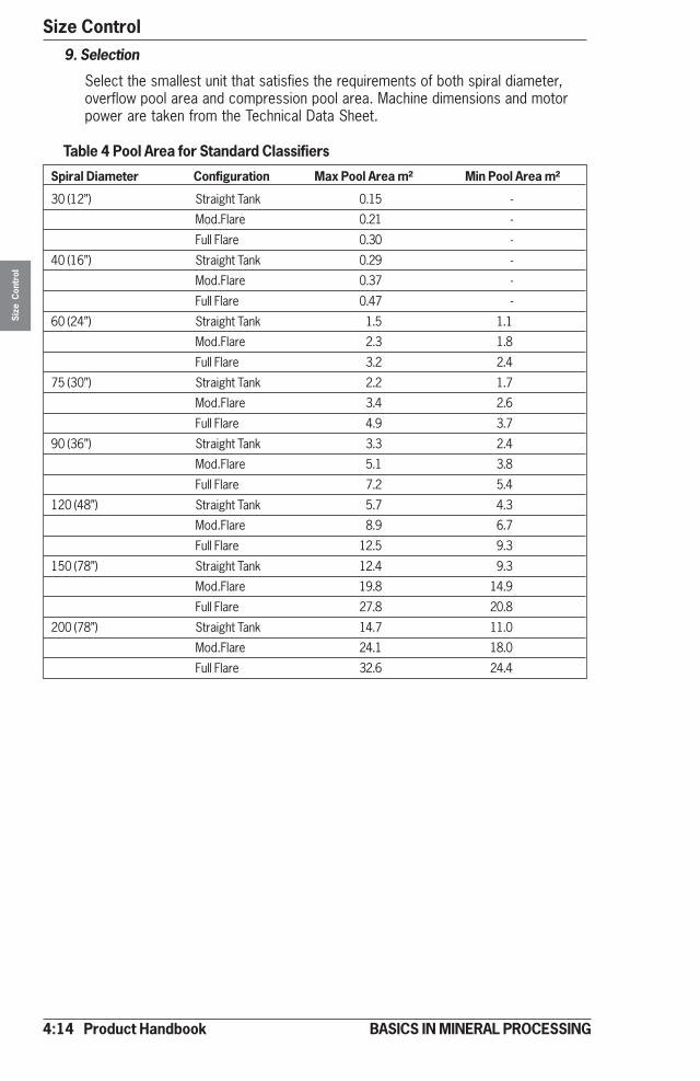
4:14 Product Handbook
Size ControlSi
ze C
ontr
ol
BASICS IN MINERAL PROCESSING
9. Selection
Select the smallest unit that satisfies the requirements of both spiral diameter,overflow pool area and compression pool area. Machine dimensions and motorpower are taken from the Technical Data Sheet.
Table 4 Pool Area for Standard Classifiers
Spiral Diameter Configuration Max Pool Area m² Min Pool Area m²
30 (12”) Straight Tank 0.15 -
Mod.Flare 0.21 -
Full Flare 0.30 -
40 (16”) Straight Tank 0.29 -
Mod.Flare 0.37 -
Full Flare 0.47 -
60 (24”) Straight Tank 1.5 1.1
Mod.Flare 2.3 1.8
Full Flare 3.2 2.4
75 (30”) Straight Tank 2.2 1.7
Mod.Flare 3.4 2.6
Full Flare 4.9 3.7
90 (36”) Straight Tank 3.3 2.4
Mod.Flare 5.1 3.8
Full Flare 7.2 5.4
120 (48”) Straight Tank 5.7 4.3
Mod.Flare 8.9 6.7
Full Flare 12.5 9.3
150 (78”) Straight Tank 12.4 9.3
Mod.Flare 19.8 14.9
Full Flare 27.8 20.8
200 (78”) Straight Tank 14.7 11.0
Mod.Flare 24.1 18.0
Full Flare 32.6 24.4

Product Handbook 4:15
Size Control
Size
Con
trol
BASICS IN MINERAL PROCESSING
Selection example data
Mineral: Sulphide oreCapacity: 20 mtph (or t/h)Percent Solids: 35 w/wSG Solids: 3.2Feed Size: 80 % -250 µmDuty: De-sliming at 100 µm
1. Mass Balance
2. Peripheral speed and sand raking efficiency
From Table 1 interpolate a peripheral speed of 0.35 m/s and efficiency of 68% for the stated SG solids 3.2 and size 80 % -250 µm.
3. “Corrected” rake capacity = 2.8 = 4.1 corrected m3/h 0.68
4. From Table 2 the smallest spiral with enough transport capacity:
60 cm diameter, single pitch and 8 r/min
5. Calculate the Equivalent Particle Size = 100 x √ (3.2 - 1) / 1.65 = 115 µm
6. Read the settling rate in Diagram 1 of a 115 µm particle at 12 % solids v/v.The settling rate is about 19 m/h.
7. Calculate Overflow Pool Area = 39.7/(0.7x19) = 3.0 m²
8. Read settling rate in Diagram 1 of a 115 µm particle at 40 %v/v: 2.2 m/h
9. Calculate Compression Pool Area [5 /(3.2 x 0.4)] / (0.7 x 0.8 x 2.2)= 3.2 m2
10. The smallest classifier with large enough pool area (3.2 m² required) is SC 60FF-1 (Table 4). With single pitch and 8 r/min (Table 2) required raking capacityis obtained.
+100 µm–
20 35 15
36 42
15 30 11.8
35 40
5 80 56
1.25 2.8
MTPHsolids
%solidsbyweight
MTPHwater
m3/hslurry
%solidsbyvolume
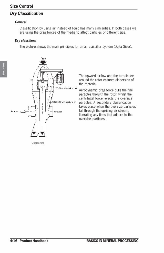
4:16 Product Handbook
Size ControlSi
ze C
ontr
ol
BASICS IN MINERAL PROCESSING
Dry Classification
General
Classification by using air instead of liquid has many similarities. In both cases weare using the drag forces of the media to affect particles of different size.
Dry classifiers
The picture shows the main principles for an air classifier system (Delta Sizer).
The upward airflow and the turbulencearound the rotor ensures dispersion ofthe material.
Aerodynamic drag force pulls the fineparticles through the rotor, whilst thecentrifugal force rejects the oversizeparticles. A secondary classificationtakes place when the oversize particlesfall through the uprising air stream,liberating any fines that adhere to theoversize particles.
Coarse fine
Air outlet

Product Handbook 4:17
Size Control
Size
Con
trol
BASICS IN MINERAL PROCESSING
Size Control in Crushing and Grinding Circuits
Crushing circuits - open screening
• Screening ahead of a crusher avoids packing• Less wear in the crusher• Higher total capacity• The screening media is “controlling” the product
in two dimensions. No “flaky shortcuts”.
Crushing circuits - closed screening
• The screens are lowering the capacity• Calibration of the product is improved• Better cubical shape• Higher reduction ratio
Grinding circuits – screening
• Used for “trapping critical sizes” in AG - SAG circuits (1)• Used for taking out size fractions from AG circuits for pebble grinding (1)• Used in circuits with heavy minerals – avoiding over grinding (fine screening) (2)• Screens being static (fixed cut point) are not too tolerant to changes in product
size, causing variations in circulating loads.• Mechanical damage or clogging of screening media can disturb operation.
Grinding circuits – classification
• Classifiers being dynamic (floating cut point) are more tolerant to changes inproduct size as the cut point is moving with the changes
• Cyclones, being most common, are effective as classifiers at cut points below200 microns (1)
• Spiral classifiers are effective as classifiers at cut points up to 800 microns.For the coarse fraction solids up to 50mm (2”) can be removed by the spiral.
• Spiral classifiers and cyclones can be used complementary if cut point iscoarser than 200 microns. (2)
1 2
1 2

4:18 Product Handbook
Size ControlSi
ze C
ontr
ol
BASICS IN MINERAL PROCESSING
FEEDHOPPER
CLASSIFIER DUSTCOLLECTOR
CYCLONE
MILL
FAN
PRODUCT
OPTION B
OPTION A
OPTION:“IN CIRCUIT DRYING” AIR HEATER
1. Grinding mill2. Classifier3. Cyclone for product recovery4. Main fan for circuit air flow5. Dust collector for cleaning of
exhaust air6. ”In circuit heater” for moistures
feed
Dry classifier system
A typical dry classifier system is shown below. Due to the difference in viscositybetween water and air the installation volume is quite different, see page 4:24
• Normally used for mineral fillerproduction
• Voluminous installation due to lowsolids content per m3 of air
• Dust collector needed for bleed -off air
• Sensitive to moisture• Low wear rate• Products down to 99% below 10
micron
1
2 3
4
5
6
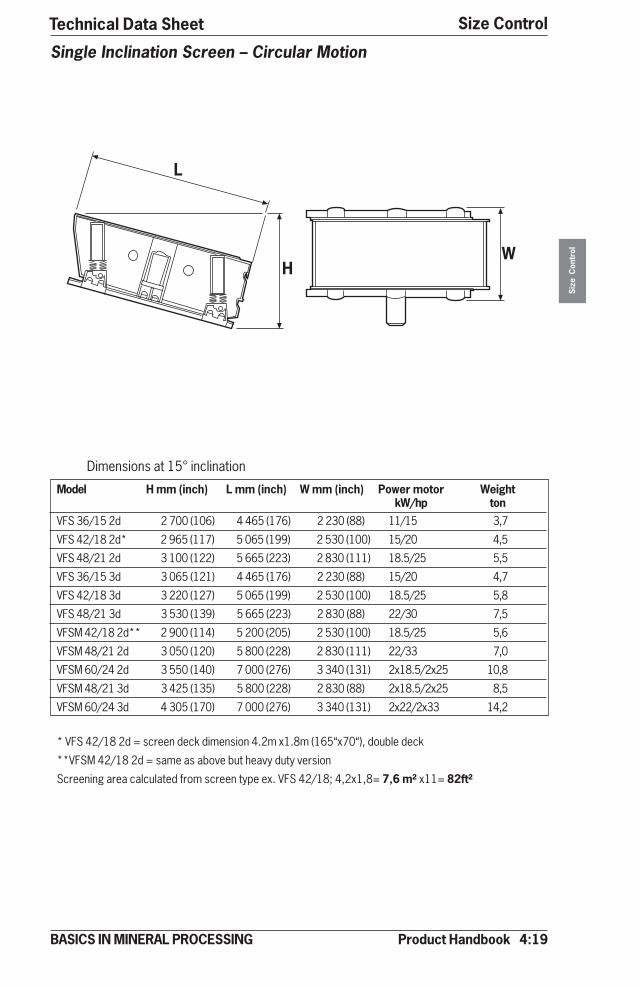
Product Handbook 4:19
Size Control
Size
Con
trol
BASICS IN MINERAL PROCESSING
Technical Data Sheet
Dimensions at 15° inclination
Model H mm (inch) L mm (inch) W mm (inch) Power motor WeightkW/hp ton
VFS 36/15 2d 2 700 (106) 4 465 (176) 2 230 (88) 11/15 3,7
VFS 42/18 2d* 2 965 (117) 5 065 (199) 2 530 (100) 15/20 4,5
VFS 48/21 2d 3 100 (122) 5 665 (223) 2 830 (111) 18.5/25 5,5
VFS 36/15 3d 3 065 (121) 4 465 (176) 2 230 (88) 15/20 4,7
VFS 42/18 3d 3 220 (127) 5 065 (199) 2 530 (100) 18.5/25 5,8
VFS 48/21 3d 3 530 (139) 5 665 (223) 2 830 (88) 22/30 7,5
VFSM 42/18 2d** 2 900 (114) 5 200 (205) 2 530 (100) 18.5/25 5,6
VFSM 48/21 2d 3 050 (120) 5 800 (228) 2 830 (111) 22/33 7,0
VFSM 60/24 2d 3 550 (140) 7 000 (276) 3 340 (131) 2x18.5/2x25 10,8
VFSM 48/21 3d 3 425 (135) 5 800 (228) 2 830 (88) 2x18.5/2x25 8,5
VFSM 60/24 3d 4 305 (170) 7 000 (276) 3 340 (131) 2x22/2x33 14,2
* VFS 42/18 2d = screen deck dimension 4.2m x1.8m (165“x70“), double deck
**VFSM 42/18 2d = same as above but heavy duty version
Screening area calculated from screen type ex. VFS 42/18; 4,2x1,8= 7,6 m² x11= 82ft²
Single Inclination Screen – Circular Motion
�
��

4:20 Product Handbook
Size ControlSi
ze C
ontr
ol
BASICS IN MINERAL PROCESSING
Technical Data Sheet
Model H mm (inch) L mm (inch) W mm (inch) Power motor Weight Max feedkW/hp ton mm/inch
VFO 12/10 2d 1 450 (57) 1 330 (52) 435 (17) 2x1.3/2x1,7 1,0 120/5
VFO 20/12 2d 1 515 (60) 2 380 (94) 1 700 (67) 2x2.3/2x3,1 1,6 150/6
VFO 20/12 3d 1 515 (60) 2 380 (94) 1 700 (67) 2x2.3/2x3,1 1,7 150/6
VFOM 12/10 3d* 1 390 (55) 1 460 (579 1 426 (56) 2x2.3/2x3,1 1,3 300/12
VFOM 20/12 3d 1 915 (75) 2 980 (117) 1 720 (68) 2x4.0/2x5,4 2,7 300/12
* VFOM, heavy-duty version with dual springs at feed and discharge ends
Double Inclination Screen – Linear Motion
�
�
�
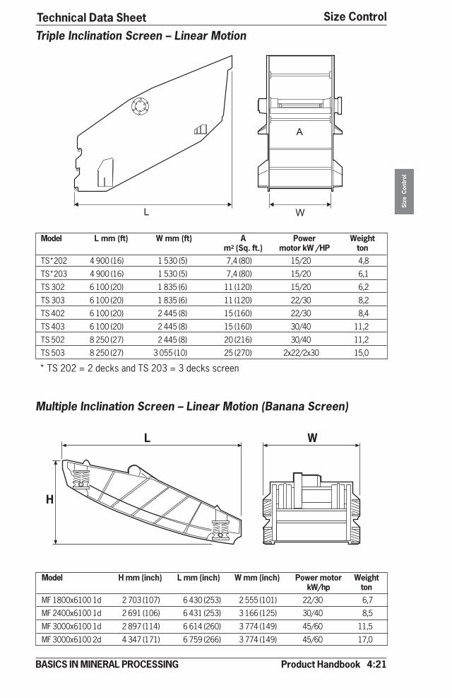
Product Handbook 4:21
Size Control
Size
Con
trol
BASICS IN MINERAL PROCESSING
Technical Data Sheet
Model L mm (ft) W mm (ft) A Power Weightm2 (Sq. ft.) motor kW /HP ton
TS*202 4 900 (16) 1 530 (5) 7,4 (80) 15/20 4,8
TS*203 4 900 (16) 1 530 (5) 7,4 (80) 15/20 6,1
TS 302 6 100 (20) 1 835 (6) 11 (120) 15/20 6,2
TS 303 6 100 (20) 1 835 (6) 11 (120) 22/30 8,2
TS 402 6 100 (20) 2 445 (8) 15 (160) 22/30 8,4
TS 403 6 100 (20) 2 445 (8) 15 (160) 30/40 11,2
TS 502 8 250 (27) 2 445 (8) 20 (216) 30/40 11,2
TS 503 8 250 (27) 3 055 (10) 25 (270) 2x22/2x30 15,0
Triple Inclination Screen – Linear Motion
Multiple Inclination Screen – Linear Motion (Banana Screen)
Model H mm (inch) L mm (inch) W mm (inch) Power motor WeightkW/hp ton
MF 1800x6100 1d 2 703 (107) 6 430 (253) 2 555 (101) 22/30 6,7
MF 2400x6100 1d 2 691 (106) 6 431 (253) 3 166 (125) 30/40 8,5
MF 3000x6100 1d 2 897 (114) 6 614 (260) 3 774 (149) 45/60 11,5
MF 3000x6100 2d 4 347 (171) 6 759 (266) 3 774 (149) 45/60 17,0
� �
�
L W
A
* TS 202 = 2 decks and TS 203 = 3 decks screen
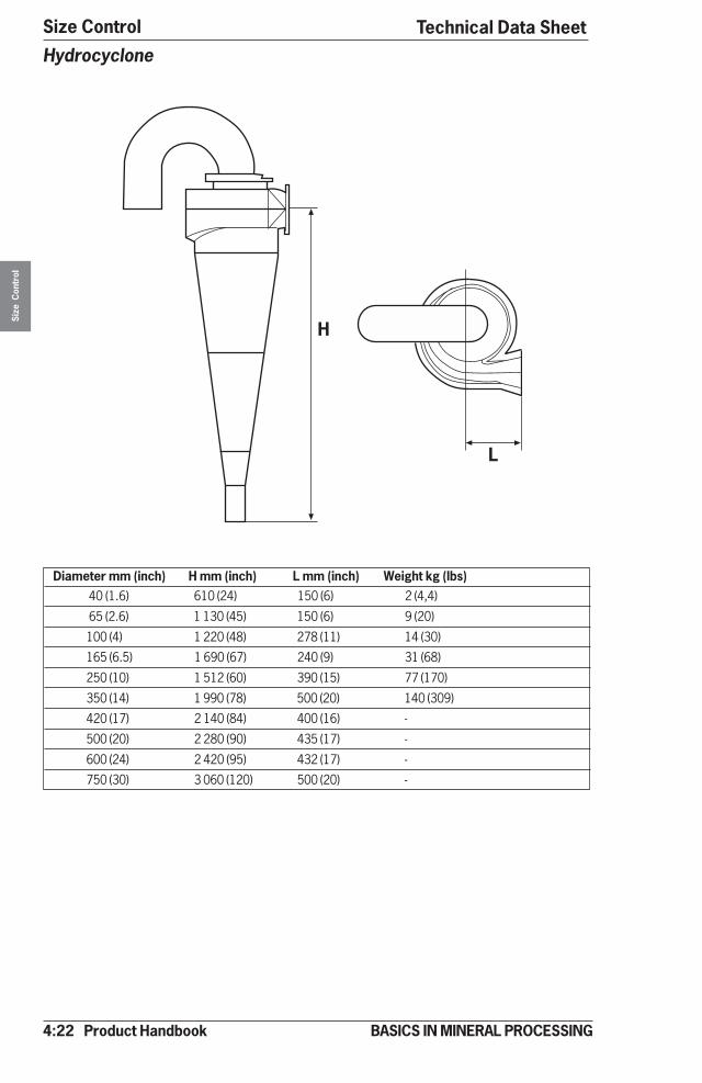
4:22 Product Handbook
Size ControlSi
ze C
ontr
ol
BASICS IN MINERAL PROCESSING
Technical Data SheetHydrocyclone
Diameter mm (inch) H mm (inch) L mm (inch) Weight kg (lbs) 40 (1.6) 610 (24) 150 (6) 2 (4,4)
65 (2.6) 1 130 (45) 150 (6) 9 (20)
100 (4) 1 220 (48) 278 (11) 14 (30)
165 (6.5) 1 690 (67) 240 (9) 31 (68)
250 (10) 1 512 (60) 390 (15) 77 (170)
350 (14) 1 990 (78) 500 (20) 140 (309)
420 (17) 2 140 (84) 400 (16) -
500 (20) 2 280 (90) 435 (17) -
600 (24) 2 420 (95) 432 (17) -
750 (30) 3 060 (120) 500 (20) -
�
�
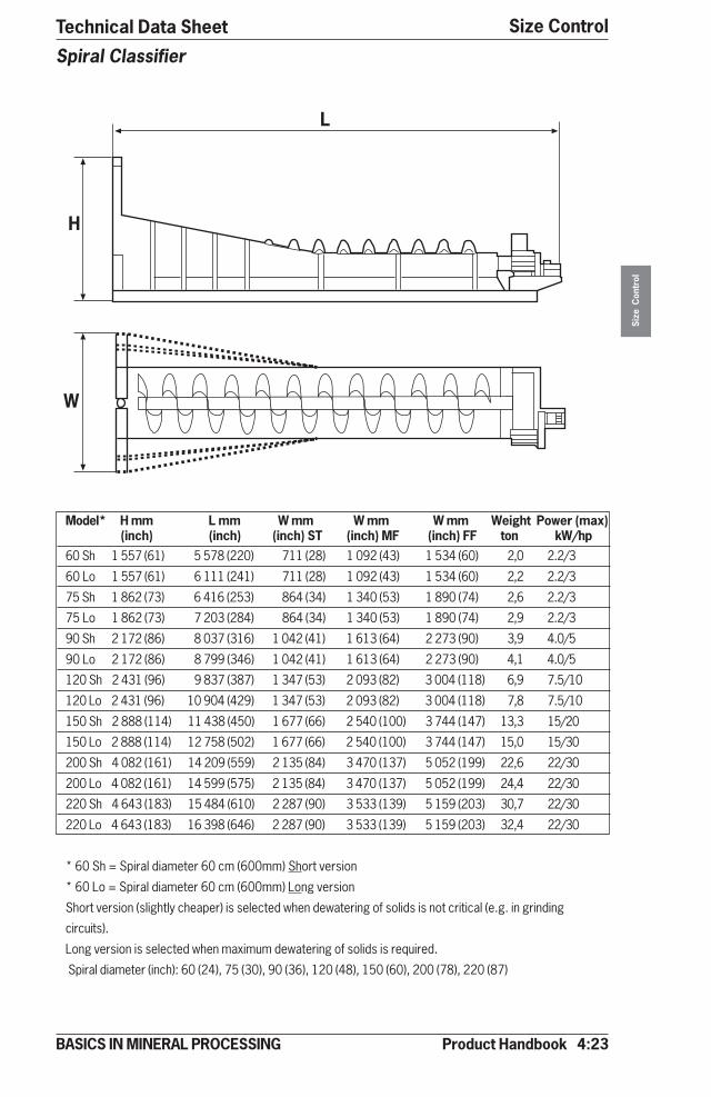
Product Handbook 4:23
Size Control
Size
Con
trol
BASICS IN MINERAL PROCESSING
Spiral Classifier
Model* H mm L mm W mm W mm W mm Weight Power (max)(inch) (inch) (inch) ST (inch) MF (inch) FF ton kW/hp
60 Sh 1 557 (61) 5 578 (220) 711 (28) 1 092 (43) 1 534 (60) 2,0 2.2/3
60 Lo 1 557 (61) 6 111 (241) 711 (28) 1 092 (43) 1 534 (60) 2,2 2.2/3
75 Sh 1 862 (73) 6 416 (253) 864 (34) 1 340 (53) 1 890 (74) 2,6 2.2/3
75 Lo 1 862 (73) 7 203 (284) 864 (34) 1 340 (53) 1 890 (74) 2,9 2.2/3
90 Sh 2 172 (86) 8 037 (316) 1 042 (41) 1 613 (64) 2 273 (90) 3,9 4.0/5
90 Lo 2 172 (86) 8 799 (346) 1 042 (41) 1 613 (64) 2 273 (90) 4,1 4.0/5
120 Sh 2 431 (96) 9 837 (387) 1 347 (53) 2 093 (82) 3 004 (118) 6,9 7.5/10
120 Lo 2 431 (96) 10 904 (429) 1 347 (53) 2 093 (82) 3 004 (118) 7,8 7.5/10
150 Sh 2 888 (114) 11 438 (450) 1 677 (66) 2 540 (100) 3 744 (147) 13,3 15/20
150 Lo 2 888 (114) 12 758 (502) 1 677 (66) 2 540 (100) 3 744 (147) 15,0 15/30
200 Sh 4 082 (161) 14 209 (559) 2 135 (84) 3 470 (137) 5 052 (199) 22,6 22/30
200 Lo 4 082 (161) 14 599 (575) 2 135 (84) 3 470 (137) 5 052 (199) 24,4 22/30
220 Sh 4 643 (183) 15 484 (610) 2 287 (90) 3 533 (139) 5 159 (203) 30,7 22/30
220 Lo 4 643 (183) 16 398 (646) 2 287 (90) 3 533 (139) 5 159 (203) 32,4 22/30
* 60 Sh = Spiral diameter 60 cm (600mm) Short version
* 60 Lo = Spiral diameter 60 cm (600mm) Long version
Short version (slightly cheaper) is selected when dewatering of solids is not critical (e.g. in grinding
circuits).
Long version is selected when maximum dewatering of solids is required.
Spiral diameter (inch): 60 (24), 75 (30), 90 (36), 120 (48), 150 (60), 200 (78), 220 (87)
�
�
�
Technical Data Sheet
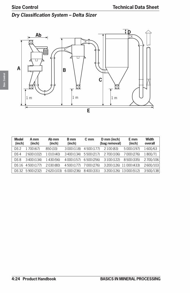
4:24 Product Handbook
Size ControlSi
ze C
ontr
ol
BASICS IN MINERAL PROCESSING
Dry Classification System – Delta Sizer
Model A mm Ab mm B mm C mm D mm (inch) E mm Width (inch) (inch) (inch) (inch) (bag removal) (inch) overallDS 2 1 700 (67) 850 (33) 3 000 (118) 4 500 (177) 2 100 (83) 5 000 (197) 1 600/63
DS 4 2 600 (102) 1 010 (40) 3 400 (134) 5 500 (217) 2 700 (106) 7 000 (276) 1 800/71
DS 8 3 400 (134) 1 430 (56) 4 000 (157) 6 500 (256) 3 100 (122) 8 500 (335) 2 700/106
DS 16 4 500 (177) 2 030 (80) 4 500 (177) 7 000 (276) 3 200 (126) 11 000 (433) 2 600/103
DS 32 5 900 (232) 2 620 (103) 6 000 (236) 8 400 (331) 3 200 (126) 13 000 (512) 3 500/138
��
� �
�
���������
Technical Data Sheet
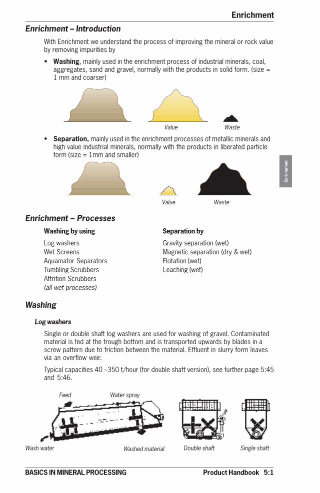
Product Handbook 5:1
Enrichment
Enri
chm
ent
BASICS IN MINERAL PROCESSING
Enrichment – IntroductionWith Enrichment we understand the process of improving the mineral or rock valueby removing impurities by
• Washing, mainly used in the enrichment process of industrial minerals, coal,aggregates, sand and gravel, normally with the products in solid form. (size =1 mm and coarser)
Value Waste
• Separation, mainly used in the enrichment processes of metallic minerals andhigh value industrial minerals, normally with the products in liberated particleform (size = 1mm and smaller)
Value Waste
Enrichment – ProcessesWashing by using Separation by
Log washers Gravity separation (wet)Wet Screens Magnetic separation (dry & wet)Aquamator Separators Flotation (wet)Tumbling Scrubbers Leaching (wet)Attrition Scrubbers(all wet processes)
Washing
Log washers
Single or double shaft log washers are used for washing of gravel. Contaminatedmaterial is fed at the trough bottom and is transported upwards by blades in ascrew pattern due to friction between the material. Effluent in slurry form leavesvia an overflow weir.
Typical capacities 40 –350 t/hour (for double shaft version), see further page 5:45and 5:46.
Feed
Wash water
Water spray
Washed material Double shaft Single shaft
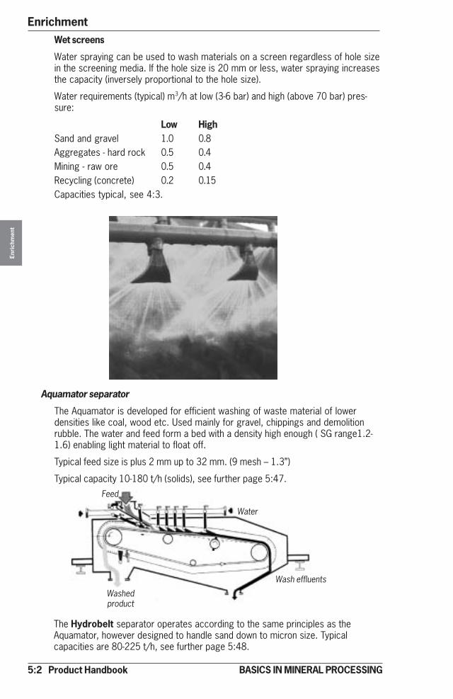
5:2 Product Handbook
EnrichmentEn
rich
men
t
BASICS IN MINERAL PROCESSING
Wet screens
Water spraying can be used to wash materials on a screen regardless of hole sizein the screening media. If the hole size is 20 mm or less, water spraying increasesthe capacity (inversely proportional to the hole size).
Water requirements (typical) m3/h at low (3-6 bar) and high (above 70 bar) pres-sure:
Low HighSand and gravel 1.0 0.8Aggregates - hard rock 0.5 0.4Mining - raw ore 0.5 0.4Recycling (concrete) 0.2 0.15Capacities typical, see 4:3.
Aquamator separator
The Aquamator is developed for efficient washing of waste material of lowerdensities like coal, wood etc. Used mainly for gravel, chippings and demolitionrubble. The water and feed form a bed with a density high enough ( SG range1.2-1.6) enabling light material to float off.
Typical feed size is plus 2 mm up to 32 mm. (9 mesh – 1.3”)
Typical capacity 10-180 t/h (solids), see further page 5:47.
The Hydrobelt separator operates according to the same principles as theAquamator, however designed to handle sand down to micron size. Typicalcapacities are 80-225 t/h, see further page 5:48.
Washedproduct
Feed
Water
Wash effluents
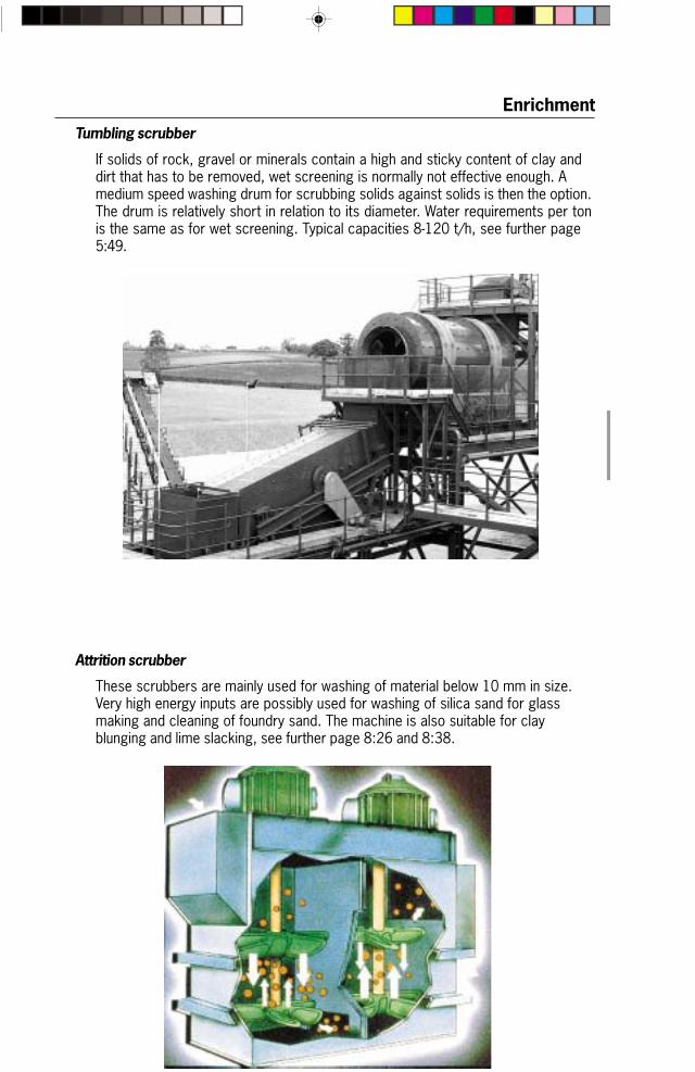
Product Handbook 5:3
Enrichment
BASICS IN MINERAL PROCESSING
Tumbling scrubber
If solids of rock, gravel or minerals contain a high and sticky content of clay anddirt that has to be removed, wet screening is normally not effective enough. Amedium speed washing drum for scrubbing solids against solids is then the option.The drum is relatively short in relation to its diameter. Water requirements per tonis the same as for wet screening. Typical capacities 8-120 t/h, see further page5:49.
Attrition scrubber
These scrubbers are mainly used for washing of material below 10 mm in size.Very high energy inputs are possibly used for washing of silica sand for glassmaking and cleaning of foundry sand. The machine is also suitable for clayblunging and lime slacking, see further page 8:26 and 8:38.

5:4 Product Handbook
EnrichmentEn
rich
men
t
BASICS IN MINERAL PROCESSING
PRIMARY TREATMENT SECONDARY TREATMENT FINAL TREATMENT
Alternativedisposal
Finaldisposal
Slurry feed
1. Hydrocyclone2. Dewatering spiral3. Dewatering screen
6. Simple Pressure filter*7. Belt press**Not covered in this handbook
Wash Water Treatment
General
All washing operations are normally consuming a lot of expensive water. Not onlycostly, but also containing a lot of washing effluents both coarse and fine. Waterand effluents that have to be processed partly to recover some value (coarsematerial and water), partly to protect the environment from damage (sludgefractions).Most washing operations today must have systems for this treatment.
Wash water treatment stages
Depending on local conditions and restrictions, one, two or three treatment stagesmay be required, see below.
•••••
‚‚‚‚‚
ƒƒƒƒƒ
„„„„„
……………
†††††
‡‡‡‡‡
Wash water treatment – closed system
After recovery of coarser material the fines can be treated in a closed systemrecovering all process water and bringing the fine solids into a transportableform.
4. Conventional clarifier5. Compact clarifier
For more information see section 6!
Recovered water
Recovered water
Feed
Sedimentation
Dewatering
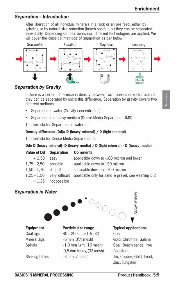
Product Handbook 5:5
Enrichment
Enri
chm
ent
BASICS IN MINERAL PROCESSING
Separation – IntroductionAfter liberation of all individual minerals in a rock or an ore feed, either bygrinding or by natural size reduction (beach sands a.o.) they can be separatedindividually. Depending on their behaviour, different technologies are applied. Wewill cover the classical methods of separation as per below.
Separation by GravityIf there is a certain difference in density between two minerals or rock fractionsthey can be separated by using this difference. Separation by gravity covers twodifferent methods.
• Separation in water (Gravity concentration)
• Separation in a heavy medium (Dense Media Separation, DMS)
The formula for Separation in water is:
Density difference (Dd)= D (heavy mineral) / D (light mineral)
The formula for Dense Media Separation is:
Dd= D (heavy mineral)- D (heavy media) / D (light mineral) - D (heavy media)
Value of Dd Separation Comments + 2,50 easy applicable down to -100 micron and lower1,75 – 2,50 possible applicable down to 150 micron1,50 – 1,75 difficult applicable down to 1700 micron1,25 – 1,50 very difficult applicable only for sand & gravel, see washing 5:2 < 1,25 not possible
Separation in Water
Equipment Particle size range Typical applicationsCoal Jigs 40 – 200 mm (1,6 - 8”) CoalMineral Jigs - 6 mm (31/2 mesh) Gold, Chromite, GalenaSpirals - 1,0 mm light, (16 mesh) Coal, Beach sands, Iron
-0,5 mm heavy, (32 mesh) CassiteritShaking tables - 3 mm (7 mesh) Tin, Copper, Gold, Lead,
Zinc, Tungsten
� �
����� ����
Realtive velocityGravimetric Flotation Magnetic Leaching
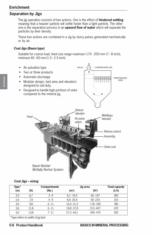
5:6 Product Handbook
EnrichmentEn
rich
men
t
BASICS IN MINERAL PROCESSING
Separation by JigsThe jig operation consists of two actions. One is the effect of hindered settlingmeaning that a heavier particle will settle faster than a light particle. The otherone is the separation process in an upward flow of water which will separate theparticles by their density.
These two actions are combined in a Jig by slurry pulses generated mechanicallyor by air.
Coal Jigs (Baum type)
Suitable for coarse load, feed size range maximum 175 - 200 mm (7 - 8 inch),minimum 40 - 60 mm (1.5 - 2.5 inch).
• Air pulsation type• Two or three products• Automatic discharge• Modular design, bed area and elevators
designed to suit duty.• Designed to handle high portions of sinks
compared to the mineral jig.
Coal Jigs – sizing
Type* Compartments Jig area Feed capacity(m) (ft) (No.) (m2) (ft2) (t/h)
2,0 6,7 3 - 9 6,1 - 18,3 66 - 197 2602,4 7,9 4 - 9 8,4 - 20,4 90 - 219 3153,0 9,8 6 - 11 16,5 - 31,5 178 - 339 3903,6 11,8 6 - 11 19,8 - 37,8 213 - 407 4704,2 13,8 7 - 11 27,3 - 44,1 294 - 474 550
Feed
Refuseelevator
Middlingselevator
Refuse control
Assembly
Clean coal
Air pulsevalves
Baum WasherMcNally Norton System
*Type refers to width of jig bed.
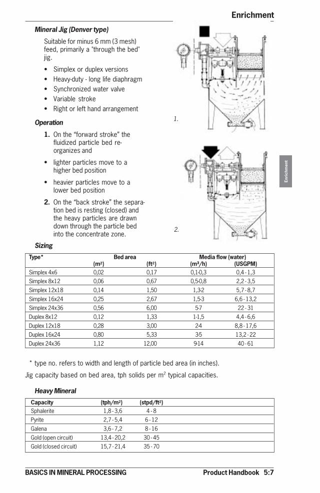
Product Handbook 5:7
Enrichment
Enri
chm
ent
BASICS IN MINERAL PROCESSING
Mineral Jig (Denver type)
Suitable for minus 6 mm (3 mesh)feed, primarily a "through the bed"jig.
• Simplex or duplex versions• Heavy-duty - long life diaphragm• Synchronized water valve• Variable stroke• Right or left hand arrangement
Operation
1. On the “forward stroke” thefluidized particle bed re-organizes and
• lighter particles move to ahigher bed position
• heavier particles move to alower bed position
2. On the “back stroke” the separa-tion bed is resting (closed) andthe heavy particles are drawndown through the particle bedinto the concentrate zone.
Sizing
Type* Bed area Media flow (water)(m2) (ft2) (m³/h) (USGPM)
Simplex 4x6 0,02 0,17 0,1-0,3 0,4 - 1,3Simplex 8x12 0,06 0,67 0,5-0,8 2,2 - 3,5Simplex 12x18 0,14 1,50 1,3-2 5,7 - 8,7Simplex 16x24 0,25 2,67 1,5-3 6,6 - 13,2Simplex 24x36 0,56 6,00 5-7 22 - 31Duplex 8x12 0,12 1,33 1-1,5 4,4 - 6,6Duplex 12x18 0,28 3,00 2-4 8,8 - 17,6Duplex 16x24 0,80 5,33 3-5 13,2 - 22Duplex 24x36 1,12 12,00 9-14 40 - 61
* type no. refers to width and length of particle bed area (in inches).
Jig capacity based on bed area, tph solids per m2 typical capacities.
Heavy Mineral
Capacity (tph/m2) (stpd/ft2)Sphalerite 1,8 - 3,6 4 - 8Pyrite 2,7 - 5,4 6 - 12Galena 3,6 - 7,2 8 - 16Gold (open circuit) 13,4 - 20,2 30 - 45Gold (closed circuit) 15,7 - 21,4 35 - 70
1.
2.
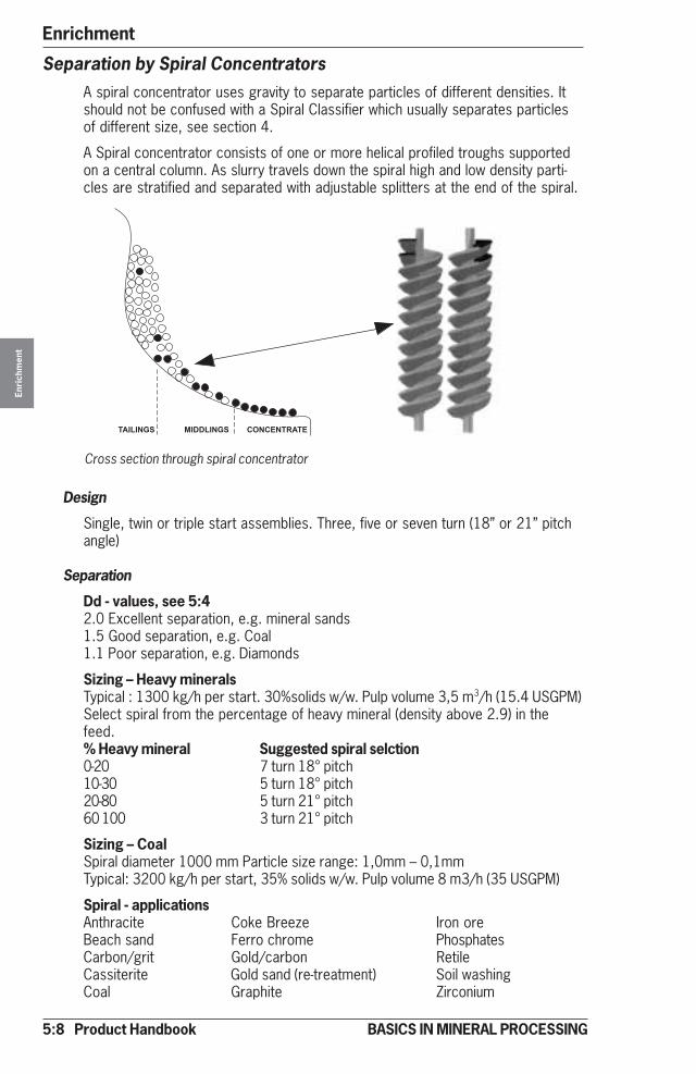
5:8 Product Handbook
EnrichmentEn
rich
men
t
BASICS IN MINERAL PROCESSING
Separation by Spiral ConcentratorsA spiral concentrator uses gravity to separate particles of different densities. Itshould not be confused with a Spiral Classifier which usually separates particlesof different size, see section 4.
A Spiral concentrator consists of one or more helical profiled troughs supportedon a central column. As slurry travels down the spiral high and low density parti-cles are stratified and separated with adjustable splitters at the end of the spiral.
������ ������� �� �������
Cross section through spiral concentrator
Design
Single, twin or triple start assemblies. Three, five or seven turn (18” or 21” pitchangle)
Separation
Dd - values, see 5:42.0 Excellent separation, e.g. mineral sands1.5 Good separation, e.g. Coal1.1 Poor separation, e.g. Diamonds
Sizing – Heavy mineralsTypical : 1300 kg/h per start. 30%solids w/w. Pulp volume 3,5 m3/h (15.4 USGPM)Select spiral from the percentage of heavy mineral (density above 2.9) in thefeed.% Heavy mineral Suggested spiral selction0-20 7 turn 18° pitch10-30 5 turn 18° pitch20-80 5 turn 21° pitch60 100 3 turn 21° pitch
Sizing – CoalSpiral diameter 1000 mm Particle size range: 1,0mm – 0,1mmTypical: 3200 kg/h per start, 35% solids w/w. Pulp volume 8 m3/h (35 USGPM)
Spiral - applicationsAnthracite Coke Breeze Iron oreBeach sand Ferro chrome PhosphatesCarbon/grit Gold/carbon RetileCassiterite Gold sand (re-treatment) Soil washingCoal Graphite Zirconium
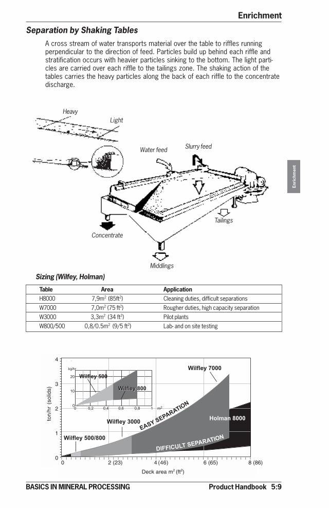
Product Handbook 5:9
Enrichment
Enri
chm
ent
BASICS IN MINERAL PROCESSING
Separation by Shaking TablesA cross stream of water transports material over the table to riffles runningperpendicular to the direction of feed. Particles build up behind each riffle andstratification occurs with heavier particles sinking to the bottom. The light parti-cles are carried over each riffle to the tailings zone. The shaking action of thetables carries the heavy particles along the back of each riffle to the concentratedischarge.
Sizing (Wilfey, Holman)
Table Area ApplicationH8000 7,9m2 (85ft2) Cleaning duties, difficult separationsW7000 7,0m2 (75 ft2) Rougher duties, high capacity separationW3000 3,3m2 (34 ft2) Pilot plantsW800/500 0,8/0.5m2 (9/5 ft2) Lab- and on site testing
Water feed Slurry feed
Concentrate
Middlings
Tailings
�
�
�
�
� � � � � � � � � � � � � � � � � � � � � � � � � � � � � � � � � � � � � � � � �
� �� �� ��� ���� ����� ����� ������
�����������
����� �������
�����
���� ��
����
����
����� !�"���
����� !�#���
����� !�$��%���
����
�
�
����������������������������������������������������������������
����� !�$��
����� !�$������� !����
�������������
���� ��������
kg/hr
0 2 (23) 4 (46) 6 (65) 8 (86)
Deck area m2 (ft2)
4
3
2
1
0
ton/
hr (
solid
s)
LightHeavy
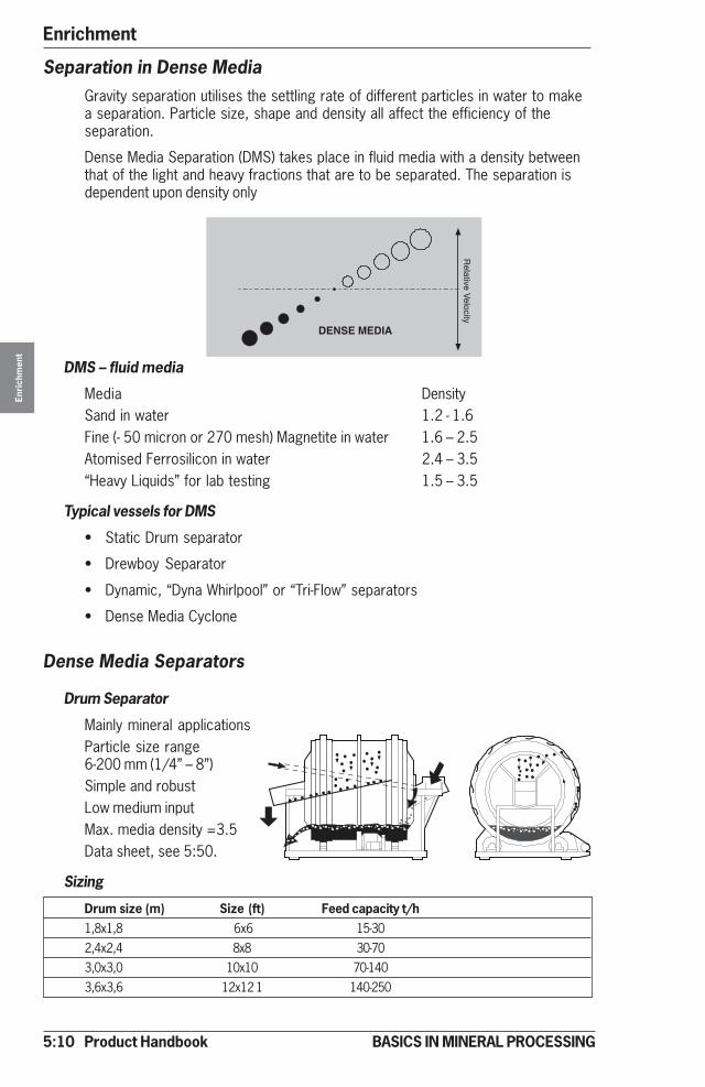
5:10 Product Handbook
EnrichmentEn
rich
men
t
BASICS IN MINERAL PROCESSING
Separation in Dense MediaGravity separation utilises the settling rate of different particles in water to makea separation. Particle size, shape and density all affect the efficiency of theseparation.
Dense Media Separation (DMS) takes place in fluid media with a density betweenthat of the light and heavy fractions that are to be separated. The separation isdependent upon density only
DMS – fluid media
Media DensitySand in water 1.2 - 1.6Fine (- 50 micron or 270 mesh) Magnetite in water 1.6 – 2.5Atomised Ferrosilicon in water 2.4 – 3.5“Heavy Liquids” for lab testing 1.5 – 3.5
Typical vessels for DMS
• Static Drum separator
• Drewboy Separator
• Dynamic, “Dyna Whirlpool” or “Tri-Flow” separators
• Dense Media Cyclone
Dense Media Separators
Drum Separator
Mainly mineral applicationsParticle size range6-200 mm (1/4” – 8”)Simple and robustLow medium inputMax. media density =3.5Data sheet, see 5:50.
Sizing
Drum size (m) Size (ft) Feed capacity t/h1,8x1,8 6x6 15-302,4x2,4 8x8 30-703,0x3,0 10x10 70-1403,6x3,6 12x12 1 140-250

Product Handbook 5:11
Enrichment
Enri
chm
ent
BASICS IN MINERAL PROCESSING
Sizing
Drewboy Dyna Whirlpool
Size*m (ft) Feed capacity t/h Model ** Feed capacity t/h1,2 (4,0) 200-350 DWP9 10-201,6 (5,0) 210-385 DWP12 20-352,0 (6,5) 225-425 DWP15 35-552,6 (8,5) 305-565 DWP18 55-753,2 (10,5) 405-6654,0 (13,0) 500-820
*Refers to inside width of bath **Refers inside diameter in inch
Drewboy
• Mainly coal applications• Particle size range 6-1200 mm (1/4"-48")• High sinks capacity up to 300 t/h• Low medium input• Max media S.G. 3.5
Data sheet, see 5:51.
Dyna Whirlpool
• For all types of DMS• Slope angle for mineral separation 25
degrees• Slope angle for coal separation 15
degrees• Particle size range 0.3-30 mm
(50 mesh - 11/4")• Capacities 10-75 t/h and unit• Can be built in series with different
separation densities• Max media S.G. 3.5• Feed pressure
100-150 kPa(14 - 22 PSI)
1. Feed preparation screens(removal of fines)
2. DMS separator (see below)
3. DMS screen (drain and washingstages)
4. Dense media circuit
5. Dilute media circuit
Dense Media Circuit
Data sheet, see 5:52.
5:12 Product Handbook
EnrichmentEn
rich
men
t
BASICS IN MINERAL PROCESSING
DMS – ApplicationsCoal TinDiamonds ManganeseIron Ore PhosphateChromite Scrap metalsFluorsparIn many cases Dense Media Separation is used for “Pre- concentration” e.g.rejecting waste material prior to further processing (typical between crushing andgrinding).
Dense Media Circuits – SizingThese systems have to be adapted to each particular case. For rough estimationsthe following figures can be used.
1. Feed preparation screens
Screens to be of horizontal vibrating type (“Low Head”) with width determined by particlesize, solids density and amount of fines.
Use the following guide-lines for screens.
Particle size Capacity/Screen widthmm (inch) t/h x m t/h x ft
6 - 100 (1/4 - 4) 90 306 - 30 (1/4 - 11/4) 50 17
0.5 - 10 (35 mesh - 3/8") 20 7
Screen lengths should be approx. 4 m (13 ft) for coarse feeds (> 6 mm) (1/4"), and 4.5 - 6 m (15 - 20 ft) forfiner feeds (< 6 mm) (1/4") all related to smaller plants (capacity 15-35 t/h).
2. Medium feed rate
1.7 m³/t (450 USG/t) dry solids for drumseparator systems4.0 m³/t (1050 USG/t) dry solids for DWPsystem
3. Medium loss
For coarse feeds (> 6 mm, 1/4") 100 g/tonsolidsFor fine feeds (< 6 mm, 1/4") 150-300 g/ton solidsdepending on material porosity.
4. Magnetic separator
Magnetic separator can be roughly sizedfrom a figure of 3.5 m³ (900 USG) dilutedmedium per ton feed solids. For magneticseparator capacities see MagneticSeparation, 5:25-26.
5. Spray screens
The width of the screens depends on theamount of spray water used (= feed to themagnetic separator) and the sink/floatdistribution.
For capacity 15-35 t/h use 4,5 m. (15 ft)For capacity 35-100 t/h use 6,0 m. (20 ft)Screen length varies with capacity andparticle size.Use 4,8 m for particle size + 6 mm (16 ftfor +1/4")Use 6,0 m for particle size + 1 mm (20 ftfor + 15 mesh)

Product Handbook 5:13
Enrichment
Enri
chm
ent
BASICS IN MINERAL PROCESSING
Separation by FlotationFlotation is a mineral separation process, which takes place in a water-mineralslurry.The surfaces of selected minerals are made hydrophobic (water-repellent) byconditioning with selective reagents. The hydrophobic particles become attachedto air bubbles that are introduced into the pulp and are carried to a froth layerabove the slurry thereby being separated from the hydrophilic (wetted) particles.
In addition to the reagents added, the flotation process depends on two mainparameters.
• Retention time needed for the separation process to occur determines thevolume and number of flotation cells required.
• Agitation and aeration needed for optimum flotation conditions, determine thetype of flotation mechanism and the power input required.
Size of cells – lengths of banks
As flotation is based on retention time we have two alternative approaches:
• Small cells and longer banks• Fewer large cells and shorter banks
The first alternative is a more conservative approach and is applicable to smalland medium tonnage operations. Using more smaller cells in flotation means
• Reduced short circuiting• Better metallurgical control• Higher recovery
The second alternative is becoming more accepted for high tonnage operationsusing large unit volume flotation machines. Modern flotation equipment givesopportunities to use larger cells and shorter circuits.
• Effective flow pattern minimizes shortcircuiting• Improved on line analyzers will maintain good metallurgical control• Less mechanical maintenance• Less energy input per volume pulp• Lower total cost
Selection of cell size is made on the basis of the largest individual cell volume thatwill give the required total flotation volume with an acceptable number of cells perbank. Typical figures for different minerals are given later in this section.
Air bubble
Particlesurface
Particle
Air bubble
Hydrofobingreagents
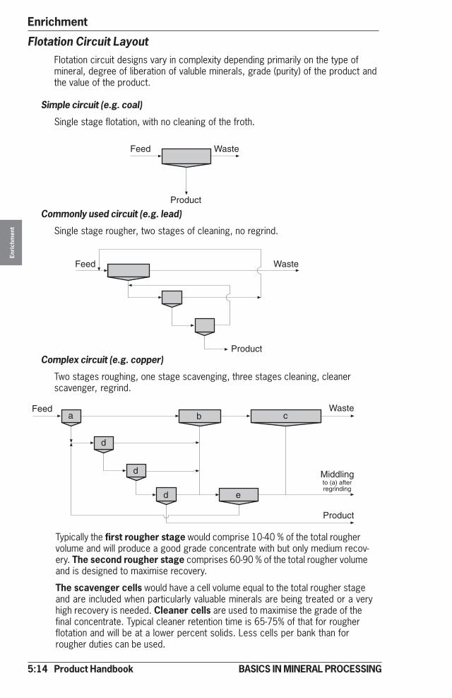
5:14 Product Handbook
EnrichmentEn
rich
men
t
BASICS IN MINERAL PROCESSING
Typically the first rougher stage would comprise 10-40 % of the total roughervolume and will produce a good grade concentrate with but only medium recov-ery. The second rougher stage comprises 60-90 % of the total rougher volumeand is designed to maximise recovery.
The scavenger cells would have a cell volume equal to the total rougher stageand are included when particularly valuable minerals are being treated or a veryhigh recovery is needed. Cleaner cells are used to maximise the grade of thefinal concentrate. Typical cleaner retention time is 65-75% of that for rougherflotation and will be at a lower percent solids. Less cells per bank than forrougher duties can be used.
Complex circuit (e.g. copper)
Two stages roughing, one stage scavenging, three stages cleaning, cleanerscavenger, regrind.
Commonly used circuit (e.g. lead)
Single stage rougher, two stages of cleaning, no regrind.
Flotation Circuit LayoutFlotation circuit designs vary in complexity depending primarily on the type ofmineral, degree of liberation of valuble minerals, grade (purity) of the product andthe value of the product.
Simple circuit (e.g. coal)
Single stage flotation, with no cleaning of the froth.
Waste
Product
Feed
Waste
Product
Feed
Waste
Product
Feed
Middling
a
d
d
d e
b c
to (a) afterregrinding

Product Handbook 5:15
Enrichment
Enri
chm
ent
BASICS IN MINERAL PROCESSING
Reactor Cell Flotation System (RCS)The RCSTM (Reactor Cell System) flotation machine utilises the patent protectedDVTM (Deep Vane) Mechanism. Flow pattern characteristics are:
• Powerful radial slurry flow patterns to tank wall (1).
• Primary return flow to underside of impeller (2).
• Secondary top recirculation (3).
Flotation enhanced due to:
• Maximum particle-bubble contacts within the mechanism and tank.
• Effective solids suspension during operation and re-suspension after shutdown.
• Effective air dispersion throughout the complete cell volume.
Features of the RCSTM (Reactor Cell System):
• Active lower zone for optimum solid suspension and particle – bubble contact.
• Upper zone with reduced turbulence to prevent particle – bubble separation.
• Quiescent cell surface to minimise particle re-entrainment.
• Circular tank with low level slurry entry and exit to minimise slurry shortcircuiting.
• Cell size 5 – 200 m3 (177 - 7063 ft3)
• V-V drive up to 50 m3. Gearbox drive above 50 m3. (V-V drives to larger volumecells optional.)
• Automatic level control by dart valves.
• Separate source of low pressure air.
• Double internal cross-flow froth launders.
• Application : The majority of mineral flotation duties.
See data sheet 5:53.
31
2
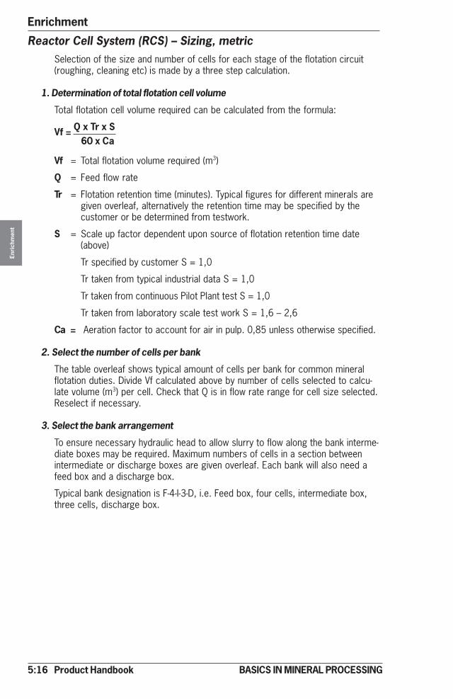
5:16 Product Handbook
EnrichmentEn
rich
men
t
BASICS IN MINERAL PROCESSING
Reactor Cell System (RCS) – Sizing, metricSelection of the size and number of cells for each stage of the flotation circuit(roughing, cleaning etc) is made by a three step calculation.
1. Determination of total flotation cell volume
Total flotation cell volume required can be calculated from the formula:
Vf = Q x Tr x S60 x Ca
Vf = Total flotation volume required (m3)
Q = Feed flow rate
Tr = Flotation retention time (minutes). Typical figures for different minerals aregiven overleaf, alternatively the retention time may be specified by thecustomer or be determined from testwork.
S = Scale up factor dependent upon source of flotation retention time date(above)
Tr specified by customer S = 1,0
Tr taken from typical industrial data S = 1,0
Tr taken from continuous Pilot Plant test S = 1,0
Tr taken from laboratory scale test work S = 1,6 – 2,6
Ca = Aeration factor to account for air in pulp. 0,85 unless otherwise specified.
2. Select the number of cells per bank
The table overleaf shows typical amount of cells per bank for common mineralflotation duties. Divide Vf calculated above by number of cells selected to calcu-late volume (m3) per cell. Check that Q is in flow rate range for cell size selected.Reselect if necessary.
3. Select the bank arrangement
To ensure necessary hydraulic head to allow slurry to flow along the bank interme-diate boxes may be required. Maximum numbers of cells in a section betweenintermediate or discharge boxes are given overleaf. Each bank will also need afeed box and a discharge box.
Typical bank designation is F-4-I-3-D, i.e. Feed box, four cells, intermediate box,three cells, discharge box.
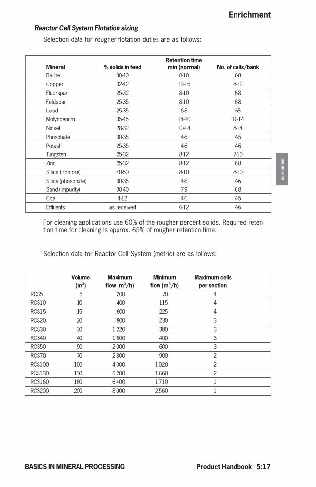
Product Handbook 5:17
Enrichment
Enri
chm
ent
BASICS IN MINERAL PROCESSING
Retention timeMineral % solids in feed min (normal) No. of cells/bankBarite 30-40 8-10 6-8Copper 32-42 13-16 8-12Fluorspar 25-32 8-10 6-8Feldspar 25-35 8-10 6-8Lead 25-35 6-8 68Molybdenum 35-45 14-20 10-14Nickel 28-32 10-14 8-14Phosphate 30-35 4-6 4-5Potash 25-35 4-6 4-6Tungsten 25-32 8-12 7-10Zinc 25-32 8-12 6-8Silica (iron ore) 40-50 8-10 8-10Silica (phosphate) 30-35 4-6 4-6Sand (impurity) 30-40 7-9 6-8Coal 4-12 4-6 4-5Effluents as received 6-12 4-6
Reactor Cell System Flotation sizing
Selection data for rougher flotation duties are as follows:
For cleaning applications use 60% of the rougher percent solids. Required reten-tion time for cleaning is approx. 65% of rougher retention time.
Selection data for Reactor Cell System (metric) are as follows:
Volume Maximum Minimum Maximum cells(m3) flow (m3/h) flow (m3/h) per section
RCS5 5 200 70 4RCS10 10 400 115 4RCS15 15 600 225 4RCS20 20 800 230 3RCS30 30 1 220 380 3RCS40 40 1 600 400 3RCS50 50 2 000 600 3RCS70 70 2 800 900 2RCS100 100 4 000 1 020 2RCS130 130 5 200 1 660 2RCS160 160 6 400 1 710 1RCS200 200 8 000 2 560 1
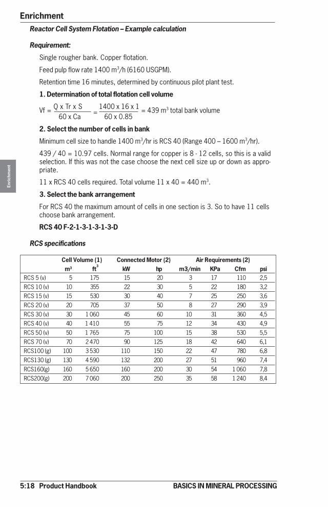
5:18 Product Handbook
EnrichmentEn
rich
men
t
BASICS IN MINERAL PROCESSING
Reactor Cell System Flotation – Example calculation
Requirement:
Single rougher bank. Copper flotation.
Feed pulp flow rate 1400 m3/h (6160 USGPM).
Retention time 16 minutes, determined by continuous pilot plant test.
1. Determination of total flotation cell volume
Vf = Q x Tr x S 1400 x 16 x 1 = 439 m3 total bank volume60 x Ca 60 x 0.85
2. Select the number of cells in bank
Minimum cell size to handle 1400 m3/hr is RCS 40 (Range 400 – 1600 m3/hr).
439 / 40 = 10.97 cells. Normal range for copper is 8 - 12 cells, so this is a validselection. If this was not the case choose the next cell size up or down as appro-priate.
11 x RCS 40 cells required. Total volume 11 x 40 = 440 m3.
3. Select the bank arrangement
For RCS 40 the maximum amount of cells in one section is 3. So to have 11 cellschoose bank arrangement.
RCS 40 F-2-1-3-1-3-1-3-D
RCS specifications
Cell Volume (1) Connected Motor (2) Air Requirements (2)m3 ft
3kW hp m3/min KPa Cfm psi
RCS 5 (v) 5 175 15 20 3 17 110 2,5RCS 10 (v) 10 355 22 30 5 22 180 3,2RCS 15 (v) 15 530 30 40 7 25 250 3,6RCS 20 (v) 20 705 37 50 8 27 290 3,9RCS 30 (v) 30 1 060 45 60 10 31 360 4,5RCS 40 (v) 40 1 410 55 75 12 34 430 4,9RCS 50 (v) 50 1 765 75 100 15 38 530 5,5RCS 70 (v) 70 2 470 90 125 18 42 640 6,1RCS100 (g) 100 3 530 110 150 22 47 780 6,8RCS130 (g) 130 4 590 132 200 27 51 960 7,4RCS160(g) 160 5 650 160 200 30 54 1 060 7,8RCS200(g) 200 7 060 200 250 35 58 1 240 8,4
=
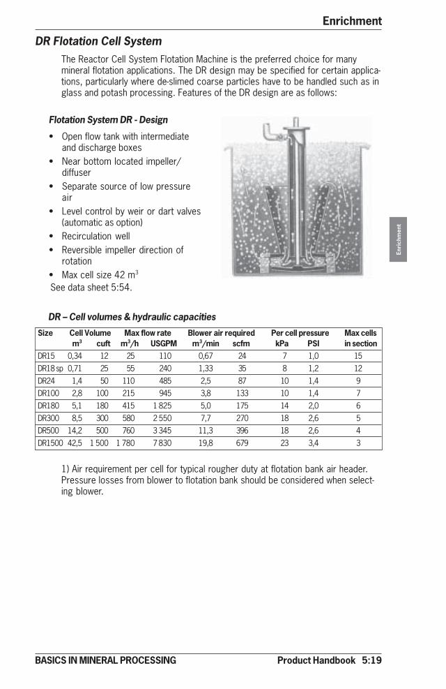
Product Handbook 5:19
Enrichment
Enri
chm
ent
BASICS IN MINERAL PROCESSING
DR Flotation Cell SystemThe Reactor Cell System Flotation Machine is the preferred choice for manymineral flotation applications. The DR design may be specified for certain applica-tions, particularly where de-slimed coarse particles have to be handled such as inglass and potash processing. Features of the DR design are as follows:
Flotation System DR - Design
• Open flow tank with intermediateand discharge boxes
• Near bottom located impeller/diffuser
• Separate source of low pressureair
• Level control by weir or dart valves(automatic as option)
• Recirculation well• Reversible impeller direction of
rotation• Max cell size 42 m3
DR – Cell volumes & hydraulic capacities
Size Cell Volume Max flow rate Blower air required Per cell pressure Max cellsm3 cuft m3/h USGPM m3/min scfm kPa PSI in section
DR15 0,34 12 25 110 0,67 24 7 1,0 15DR18 sp 0,71 25 55 240 1,33 35 8 1,2 12DR24 1,4 50 110 485 2,5 87 10 1,4 9DR100 2,8 100 215 945 3,8 133 10 1,4 7DR180 5,1 180 415 1 825 5,0 175 14 2,0 6DR300 8,5 300 580 2 550 7,7 270 18 2,6 5DR500 14,2 500 760 3 345 11,3 396 18 2,6 4DR1500 42,5 1 500 1 780 7 830 19,8 679 23 3,4 3
1) Air requirement per cell for typical rougher duty at flotation bank air header.Pressure losses from blower to flotation bank should be considered when select-ing blower.
See data sheet 5:54.
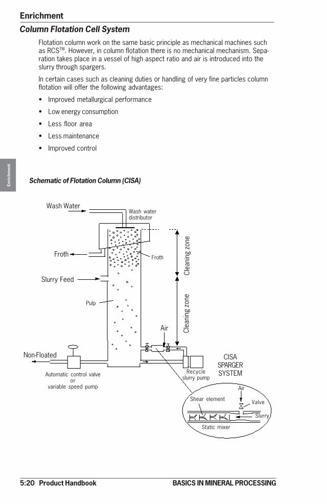
5:20 Product Handbook
EnrichmentEn
rich
men
t
BASICS IN MINERAL PROCESSING
Column Flotation Cell SystemFlotation column work on the same basic principle as mechanical machines suchas RCSTM. However, in column flotation there is no mechanical mechanism. Sepa-ration takes place in a vessel of high aspect ratio and air is introduced into theslurry through spargers.
In certain cases such as cleaning duties or handling of very fine particles columnflotation will offer the following advantages:
• Improved metallurgical performance
• Low energy consumption
• Less floor area
• Less maintenance
• Improved control
Schematic of Flotation Column (CISA)
Wash Water
Froth
Non-Floated CISASPARGERSYSTEM
Air
Slurry Feed
Clea
ning
zon
eCl
eani
ng z
one
Slurry
Pulp
Automatic control valveor
variable speed pump Air
Valve
Wash waterdistributor
Froth
Static mixer
Recycleslurry pump
Shear element
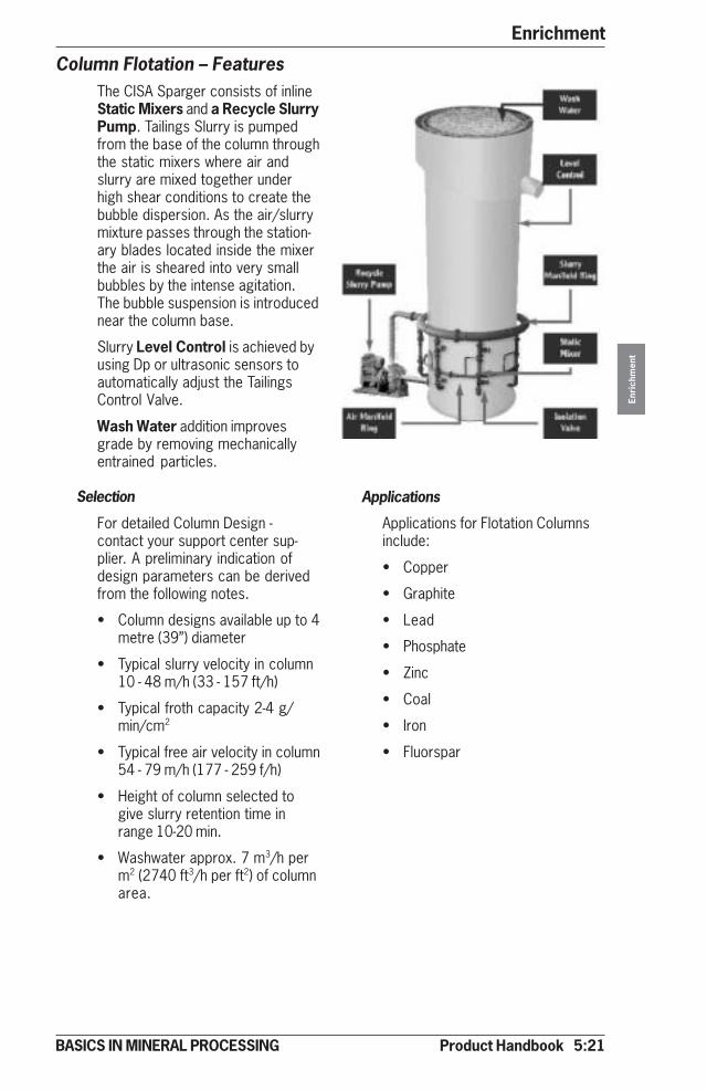
Product Handbook 5:21
Enrichment
Enri
chm
ent
BASICS IN MINERAL PROCESSING
Column Flotation – FeaturesThe CISA Sparger consists of inlineStatic Mixers and a Recycle SlurryPump. Tailings Slurry is pumpedfrom the base of the column throughthe static mixers where air andslurry are mixed together underhigh shear conditions to create thebubble dispersion. As the air/slurrymixture passes through the station-ary blades located inside the mixerthe air is sheared into very smallbubbles by the intense agitation.The bubble suspension is introducednear the column base.
Slurry Level Control is achieved byusing Dp or ultrasonic sensors toautomatically adjust the TailingsControl Valve.
Wash Water addition improvesgrade by removing mechanicallyentrained particles.
Selection
For detailed Column Design -contact your support center sup-plier. A preliminary indication ofdesign parameters can be derivedfrom the following notes.
• Column designs available up to 4metre (39”) diameter
• Typical slurry velocity in column10 - 48 m/h (33 - 157 ft/h)
• Typical froth capacity 2-4 g/min/cm2
• Typical free air velocity in column54 - 79 m/h (177 - 259 f/h)
• Height of column selected togive slurry retention time inrange 10-20 min.
• Washwater approx. 7 m3/h perm2 (2740 ft3/h per ft2) of columnarea.
Applications
Applications for Flotation Columnsinclude:
• Copper
• Graphite
• Lead
• Phosphate
• Zinc
• Coal
• Iron
• Fluorspar

5:22 Product Handbook
EnrichmentEn
rich
men
t
BASICS IN MINERAL PROCESSING
Magnetic Separation – IntroductionBy creating an environment comprimising a magnetic force (Fm), a gravitionalforce (Fg) and a drag force (Fd) magnetic particles can be separated from non-magnetic particles by Magnetic Separation.
Magnetic Separation - Magnetic attraction force (Fm)
Fm = V x X x H x grad HV = particle volume (determined by process)X = magnetic susceptibility (see table below)H = magnetic field (created by the magnet system design) in mT
(milliTesla) or kGauss (kiloGauss) 1 kGauss = 100 mT = 0.1 Tgrade H = Magnetic field gradient (created by the magnet system design) in mT/m
Magnetic field and magnetic gradient are equally important factors for creat-ing the magnet attraction force.
Mineral Magnetic susceptibility (Xm x 106 emu/g)
Magnetite 20 000-80 000 Ferromagnetic (strong magnetic)Pyrrhotite 1 500-6 100
Hematite 172-290 Paramagnetic (weakly magnetic)Ilmenite 113-271
Siderite 56-64
Chromite 53-125
Biotite 23-80
Goethite 21-25
Monazite 18,9
Malachite 8,5-15,0
Bornite 8,0-14,0
Rutile 2,0
Pyrite 0,21
Cassiterite - 0,08 Diamagnetic (repelling)Fluorite - 0,285
Galena - 0,35
Calcite - 0,377
Quartz - 0,46
Gypsum -1,0
Sphalerite -1,2
Apatite - 2,64
Fd
Fg
Fd
Fg
Fm
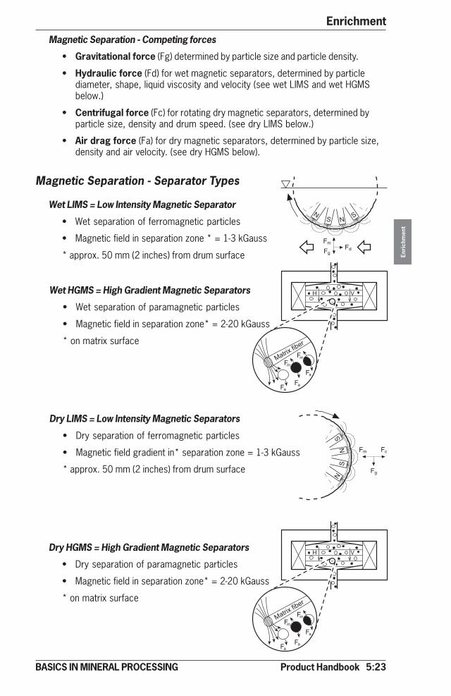
Product Handbook 5:23
Enrichment
Enri
chm
ent
BASICS IN MINERAL PROCESSING
� �
�!��"�#�$��
�%�%
%�%�
%�
� �
�!��"�#�$��
�%�%
%�%�
%�
NS
NS
FcFm
Fg
Wet HGMS = High Gradient Magnetic Separators
• Wet separation of paramagnetic particles
• Magnetic field in separation zone* = 2-20 kGauss
* on matrix surface
Magnetic Separation - Competing forces
• Gravitational force (Fg) determined by particle size and particle density.
• Hydraulic force (Fd) for wet magnetic separators, determined by particlediameter, shape, liquid viscosity and velocity (see wet LIMS and wet HGMSbelow.)
• Centrifugal force (Fc) for rotating dry magnetic separators, determined byparticle size, density and drum speed. (see dry LIMS below.)
• Air drag force (Fa) for dry magnetic separators, determined by particle size,density and air velocity. (see dry HGMS below).
Magnetic Separation - Separator Types
Wet LIMS = Low Intensity Magnetic Separator
• Wet separation of ferromagnetic particles
• Magnetic field in separation zone * = 1-3 kGauss
* approx. 50 mm (2 inches) from drum surface
Dry LIMS = Low Intensity Magnetic Separators
• Dry separation of ferromagnetic particles
• Magnetic field gradient in* separation zone = 1-3 kGauss
* approx. 50 mm (2 inches) from drum surface
NS N
S
Fd
Fm
Fg
Dry HGMS = High Gradient Magnetic Separators
• Dry separation of paramagnetic particles
• Magnetic field in separation zone* = 2-20 kGauss
* on matrix surface
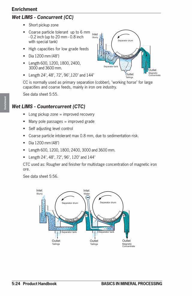
5:24 Product Handbook
EnrichmentEn
rich
men
t
BASICS IN MINERAL PROCESSING
��&���!�����'�
()*+,�
��&���!���!�-
,����-���'!��!
��'��./-��!
0�-��-!��!�
�'!��! ��-�!��
Wet LIMS - Concurrent (CC)• Short pickup zone
• Coarse particle tolerant up to 6 mm- 0.2 inch (up to 20 mm - 0.8 inchwith special tank)
• High capacities for low grade feeds
• Dia 1200 mm (48")
• Length 600, 1200, 1800, 2400,3000 and 3600 mm.
• Length 24", 48", 72", 96",120" and 144"
CC is normally used as primary separation (cobber), "working horse" for largecapacities and coarse feeds, mainly in iron ore industry.
See data sheet 5:55.
Wet LIMS - Countercurrent (CTC)• Long pickup zone = improved recovery
• Many pole passages = improved grade
• Self adjusting level control
• Coarse particle intolerant max 0.8 mm, due to sedimentation risk.
• Dia 1200 mm (48")
• Length 600, 1200, 1800, 2400, 3000 and 3600 mm.
• Length 24", 48", 72", 96", 120" and 144"
CTC used as: Rougher and finisher for multistage concentration of magnetic ironore.
See data sheet 5:56.
,����-���'!��!
��'��./-��!
()*+,� ()*+,�
��&���!���!�-
��&���!�����'�
,����-���'!��!
��&���!���!�-
��&���!�����'�
0�-��-!��!�
�'!��! ��-�!��
1�!��/-��!
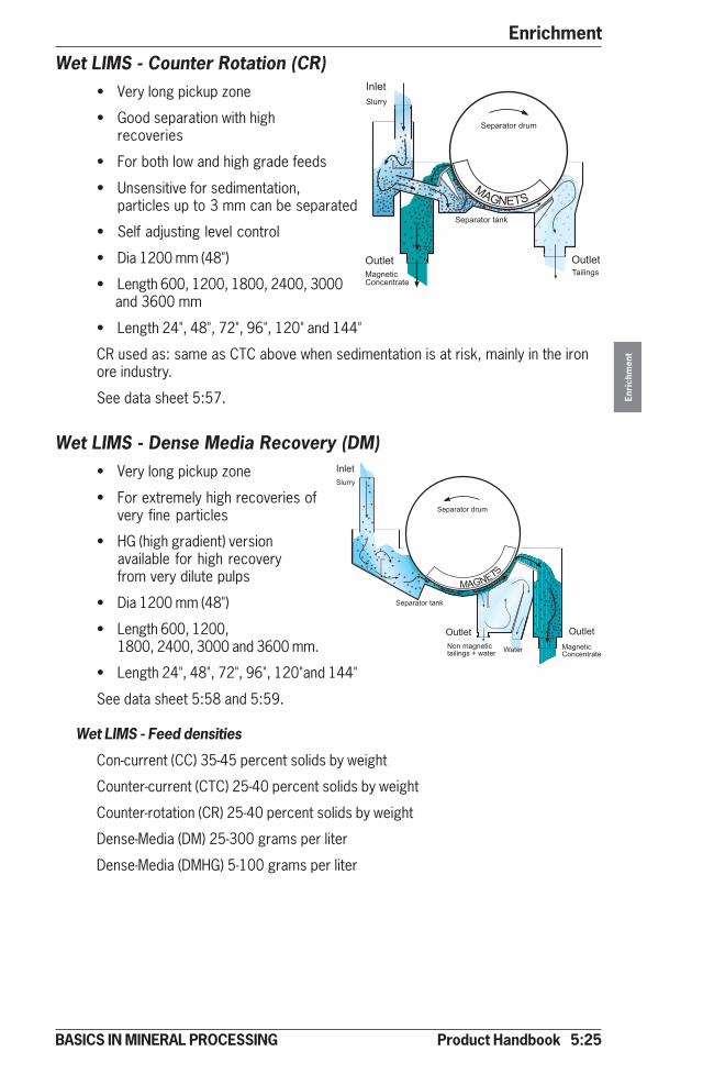
Product Handbook 5:25
Enrichment
Enri
chm
ent
BASICS IN MINERAL PROCESSING
��&���!���!�-
��'��.
��-�!��0�-��-!��!�
�'!��!
��&���!�����'�
/-��!
,����-���'!��!
()*+,�
()*+,
�
�'!��!
��&���!�����'�
��&���!���!�-
*�-����-�!��!����-���2�3�!�� 1�!�� ��-�!��
0�-��-!��!�
�'!��!
/-��!��'��.
Wet LIMS - Counter Rotation (CR)• Very long pickup zone
• Good separation with highrecoveries
• For both low and high grade feeds
• Unsensitive for sedimentation,particles up to 3 mm can be separated
• Self adjusting level control
• Dia 1200 mm (48")
• Length 600, 1200, 1800, 2400, 3000 and 3600 mm
• Length 24", 48", 72", 96", 120" and 144"
CR used as: same as CTC above when sedimentation is at risk, mainly in the ironore industry.
See data sheet 5:57.
Wet LIMS - Dense Media Recovery (DM)• Very long pickup zone
• For extremely high recoveries ofvery fine particles
• HG (high gradient) versionavailable for high recoveryfrom very dilute pulps
• Dia 1200 mm (48")
• Length 600, 1200,1800, 2400, 3000 and 3600 mm.
• Length 24", 48", 72", 96", 120"and 144"
See data sheet 5:58 and 5:59.
Wet LIMS - Feed densities
Con-current (CC) 35-45 percent solids by weight
Counter-current (CTC) 25-40 percent solids by weight
Counter-rotation (CR) 25-40 percent solids by weight
Dense-Media (DM) 25-300 grams per liter
Dense-Media (DMHG) 5-100 grams per liter
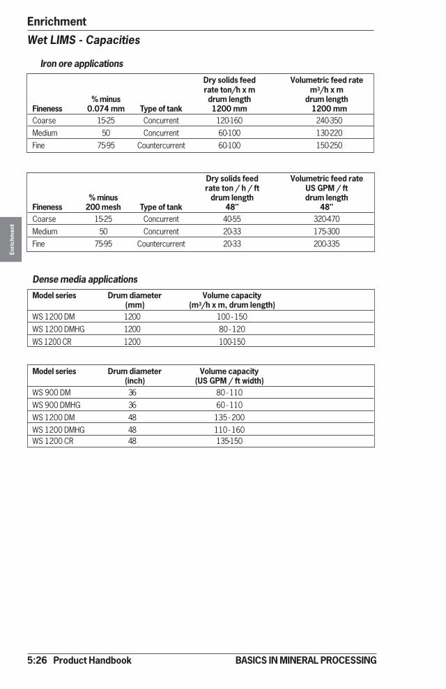
5:26 Product Handbook
EnrichmentEn
rich
men
t
BASICS IN MINERAL PROCESSING
Wet LIMS - Capacities
Iron ore applications
Dry solids feed Volumetric feed raterate ton/h x m m3/h x m
% minus drum length drum lengthFineness 0.074 mm Type of tank 1200 mm 1200 mmCoarse 15-25 Concurrent 120-160 240-350Medium 50 Concurrent 60-100 130-220Fine 75-95 Countercurrent 60-100 150-250
Dry solids feed Volumetric feed raterate ton / h / ft US GPM / ft
% minus drum length drum lengthFineness 200 mesh Type of tank 48" 48"Coarse 15-25 Concurrent 40-55 320-470Medium 50 Concurrent 20-33 175-300Fine 75-95 Countercurrent 20-33 200-335
Dense media applications
Model series Drum diameter Volume capacity(mm) (m3/h x m, drum length)
WS 1200 DM 1200 100 - 150WS 1200 DMHG 1200 80 - 120
WS 1200 CR 1200 100-150
Model series Drum diameter Volume capacity(inch) (US GPM / ft width)
WS 900 DM 36 80 - 110WS 900 DMHG 36 60 - 110WS 1200 DM 48 135 - 200WS 1200 DMHG 48 110 - 160WS 1200 CR 48 135-150
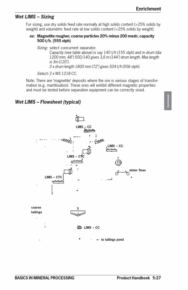
Product Handbook 5:27
Enrichment
Enri
chm
ent
BASICS IN MINERAL PROCESSING
Wet LIMS – SizingFor sizing, use dry solids feed rate normally at high solids content (>25% solids byweight) and volumetric feed rate at low solids content (<25% solids by weight)
ex: Magnetite rougher, coarse particles 20% minus 200 mesh, capacity500 t/h. (555 stph)
Sizing: select concurrent separator.Capacity (see table above) is say 140 t/h (155 stph) and m drum (dia1200 mm, 48") 500/140 gives 3,6 m (144") drum length. Max lengthis 3m (120").2 x drum length 1800 mm (72") gives 504 t/h (556 stph).
Select: 2 x WS 1218 CC.
Note: There are ‘magnetite’ deposits where the ore is various stages of transfor-mation (e.g. martitisation). These ores will exhibit different magnetic propertiesand must be tested before separation equipment can be correctly sized.
Wet LIMS – Flowsheet (typical)
LIMS – CC
LIMS – CC
LIMS – CTC
LIMS – CTC
sinter fines
LIMS – CC
to tailings pond
coarsetailings
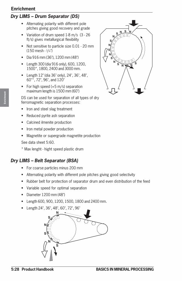
5:28 Product Handbook
EnrichmentEn
rich
men
t
BASICS IN MINERAL PROCESSING
NS
N
S
NS
NSN
N
N
N
NN N
S
S
S
S
S SS
Dry LIMS – Drum Separator (DS)• Alternating polarity with different pole
pitches giving good recovery and grade
• Variation of drum speed 1-8 m/s (3 - 26ft/s) gives metallurgical flexibility
• Not sensitive to particle size 0.01 - 20 mm(150 mesh - 3/4")
• Dia 916 mm (36"), 1200 mm (48")
• Length 300 (dia 916 only), 600, 1200,1500*, 1800, 2400 and 3000 mm.
• Length 12" (dia 36" only), 24", 36", 48",60"*, 72", 96", and 120"
• For high speed (+5 m/s) separationmaximum length is 1500 mm (60")
DS can be used for separation of all types of dryferromagnetic separation processes:
• Iron and steel slag treatment
• Reduced pyrite ash separation
• Calcined ilmenite production
• Iron metal powder production
• Magnetite or supergrade magnetite production
See data sheet 5:60.
* Max lenght - hight speed plastic drum
Dry LIMS – Belt Separator (BSA)• For coarse particles minus 200 mm
• Alternating polarity with different pole pitches giving good selectivity
• Rubber belt for protection of separator drum and even distribution of the feed
• Variable speed for optimal separation
• Diameter 1200 mm (48")
• Length 600, 900, 1200, 1500, 1800 and 2400 mm.
• Length 24", 36", 48", 60", 72", 96"

Product Handbook 5:29
Enrichment
Enri
chm
ent
BASICS IN MINERAL PROCESSING
Dry LIMS - Belt Separator (BSS)• Extremely strong separation force
for - 300 mm lump sizes
• Disc type magnets with no particle rotationgiving lower selectivity
• Rubber belt protection
• Variable speed
• Dia 1200 mm (48")
• Length 600, 1200, 1800 and 2400 mm.
• Length 24", 48", 72", 96"
BSA and BSS mainly used for separation ofcoarse ferromagnetic ores and slags
See data sheet 5:61.
Dry LIMS - Particle size in feed
DS 0-20 mm (0 - 3/4") Selectivity drops under 30 microns
BSA 5-200 mm (3/16" - 8") Selectivity drops under 5 mm (3/16")
BSS 5-300 mm (3/16" - 12") Selectivity drops under 5 mm (3/16")
Dry LIMS - Max. moisture in feed
Feed size max % H2O in feedDS - 6 mm (1/4") 5
- 1 mm (16 mesh) 0,5- 0,1 mm (150 mesh) 0,1
Dry LIMS - Recommended pole pitch (pole distance)
Feed size (mm) Pole pitch (mm) Feed size (inch) Pole pitch (inch)DS 0 - 5 25 0 - 3/16" 1"
0 - 10 45 0 - 3/8" 13/4"0 - 15 65 0 - 9/16" 25/8"0 - 20 100 0 - 3/4" 4"
BSA 5-75 105 3/16" - 3" 4"5-100 165 3/16" - 4" 65/8"5-200 250 3/16" - 8" 10"

5:30 Product Handbook
EnrichmentEn
rich
men
t
BASICS IN MINERAL PROCESSING
Dry LIMS – CapacitiesType Dia (mm) t/h and m drum lengthx) Dia (inch) st / h / ft lengthDS 916 100-150 36" 35 - 50
1 200 100-200 48" 35 - 70BSA 1 200 150-200 48 50 - 70BSS 1 200 250-400 48 85 - 135
x) Typical capacities. Individual ores subject to larger variations.
Dry LIMS - Flowsheets (typical)
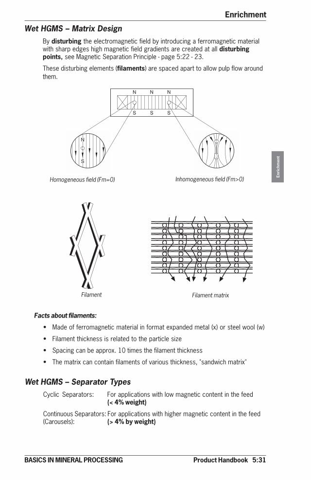
Product Handbook 5:31
Enrichment
Enri
chm
ent
BASICS IN MINERAL PROCESSING
Wet HGMS – Matrix DesignBy disturbing the electromagnetic field by introducing a ferromagnetic materialwith sharp edges high magnetic field gradients are created at all disturbingpoints, see Magnetic Separation Principle - page 5:22 - 23.
These disturbing elements (filaments) are spaced apart to allow pulp flow around
Facts about filaments:
• Made of ferromagnetic material in format expanded metal (x) or steel wool (w)
• Filament thickness is related to the particle size
• Spacing can be approx. 10 times the filament thickness
• The matrix can contain filaments of various thickness, "sandwich matrix"
Wet HGMS – Separator TypesCyclic Separators: For applications with low magnetic content in the feed
(< 4% weight)
Continuous Separators: For applications with higher magnetic content in the feed(Carousels): (> 4% by weight)
Homogeneous field (Fm=0) Inhomogeneous field (Fm>0)
Filament Filament matrix
them.
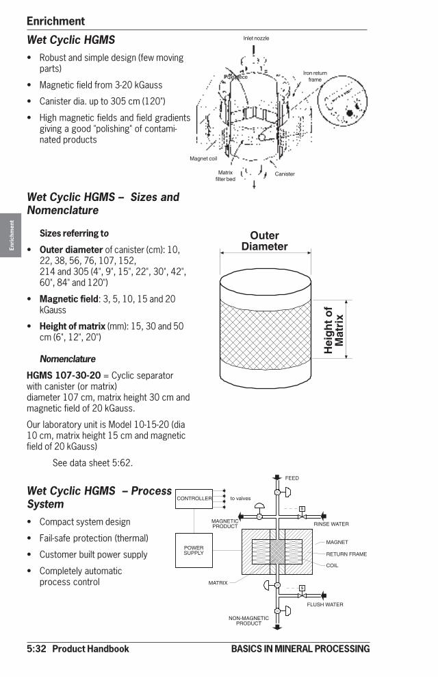
5:32 Product Handbook
EnrichmentEn
rich
men
t
BASICS IN MINERAL PROCESSING
CONTROLLER
POWERSUPPLY
FLUSH WATER
RINSE WATER
MAGNET
FEED
NON-MAGNETICPRODUCT
MATRIX
MAGNETICPRODUCT
to valves
s
s
RETURN FRAME
COIL
Wet Cyclic HGMS• Robust and simple design (few moving
parts)
• Magnetic field from 3-20 kGauss
• Canister dia. up to 305 cm (120")
• High magnetic fields and field gradientsgiving a good "polishing" of contami-nated products
Wet Cyclic HGMS – Sizes andNomenclature
Sizes referring to
• Outer diameter of canister (cm): 10,22, 38, 56, 76, 107, 152,214 and 305 (4", 9", 15", 22", 30", 42",60", 84" and 120")
• Magnetic field: 3, 5, 10, 15 and 20kGauss
• Height of matrix (mm): 15, 30 and 50cm (6", 12", 20")
Nomenclature
HGMS 107-30-20 = Cyclic separatorwith canister (or matrix)diameter 107 cm, matrix height 30 cm andmagnetic field of 20 kGauss.
Our laboratory unit is Model 10-15-20 (dia10 cm, matrix height 15 cm and magneticfield of 20 kGauss)
See data sheet 5:62.
Wet Cyclic HGMS – ProcessSystem• Compact system design
• Fail-safe protection (thermal)
• Customer built power supply
• Completely automaticprocess control
Hei
gh
t o
fM
atri
x
OuterDiameter
Inlet nozzle
Pole pieceIron return
frame
CanisterMatrixfilter bed
Magnet coil
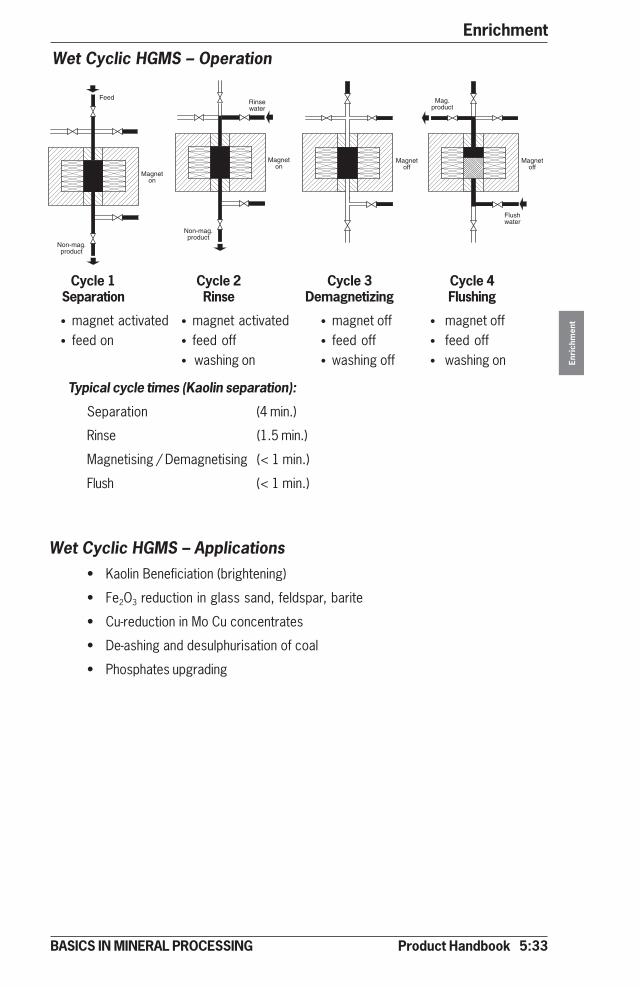
Product Handbook 5:33
Enrichment
Enri
chm
ent
BASICS IN MINERAL PROCESSING
Cycle 1 Cycle 2 Cycle 3 Cycle 4Separation Rinse Demagnetizing Flushing
• magnet activated • magnet activated • magnet off • magnet off• feed on • feed off • feed off • feed off
• washing on • washing off • washing on
Typical cycle times (Kaolin separation):
Separation (4 min.)
Rinse (1.5 min.)
Magnetising / Demagnetising (< 1 min.)
Flush (< 1 min.)
Wet Cyclic HGMS – Applications• Kaolin Beneficiation (brightening)
• Fe2O3 reduction in glass sand, feldspar, barite
• Cu-reduction in Mo Cu concentrates
• De-ashing and desulphurisation of coal
• Phosphates upgrading
Magneton
Feed
Non-mag.product
Magneton
Non-mag.product
Rinsewater
Magnetoff
Magnetoff
Mag.product
Flushwater
Wet Cyclic HGMS – Operation
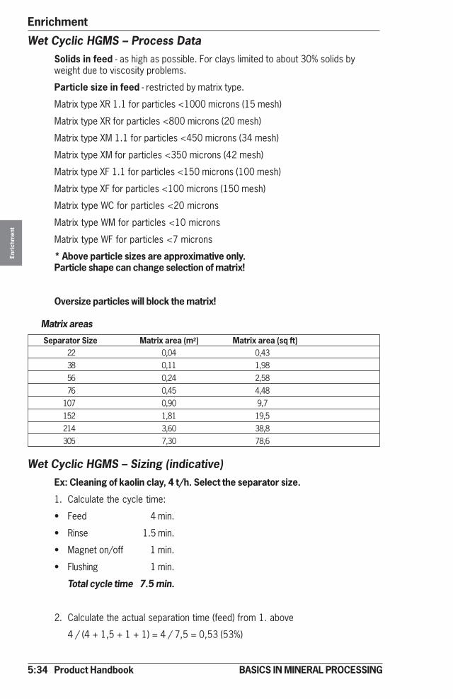
5:34 Product Handbook
EnrichmentEn
rich
men
t
BASICS IN MINERAL PROCESSING
Wet Cyclic HGMS – Process DataSolids in feed - as high as possible. For clays limited to about 30% solids byweight due to viscosity problems.
Particle size in feed - restricted by matrix type.
Matrix type XR 1.1 for particles <1000 microns (15 mesh)
Matrix type XR for particles <800 microns (20 mesh)
Matrix type XM 1.1 for particles <450 microns (34 mesh)
Matrix type XM for particles <350 microns (42 mesh)
Matrix type XF 1.1 for particles <150 microns (100 mesh)
Matrix type XF for particles <100 microns (150 mesh)
Matrix type WC for particles <20 microns
Matrix type WM for particles <10 microns
Matrix type WF for particles <7 microns
* Above particle sizes are approximative only.Particle shape can change selection of matrix!
Oversize particles will block the matrix!
Matrix areas
Separator Size Matrix area (m2) Matrix area (sq ft)22 0,04 0,4338 0,11 1,9856 0,24 2,5876 0,45 4,48
107 0,90 9,7152 1,81 19,5214 3,60 38,8305 7,30 78,6
Wet Cyclic HGMS – Sizing (indicative)Ex: Cleaning of kaolin clay, 4 t/h. Select the separator size.
1. Calculate the cycle time:
• Feed 4 min.
• Rinse 1.5 min.
• Magnet on/off 1 min.
• Flushing 1 min.
Total cycle time 7.5 min.
2. Calculate the actual separation time (feed) from 1. above
4 / (4 + 1,5 + 1 + 1) = 4 / 7,5 = 0,53 (53%)
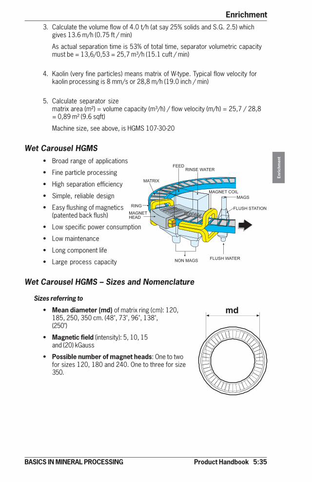
Product Handbook 5:35
Enrichment
Enri
chm
ent
BASICS IN MINERAL PROCESSING
(,4/5
%++�4/*�+�1(,+4
4/*)
()*+,�+(�
*�*� ()�
()� ()*+,�0�/6
%67����,(,/�*
%67���1(,+4
3. Calculate the volume flow of 4.0 t/h (at say 25% solids and S.G. 2.5) whichgives 13.6 m/h (0.75 ft / min)
As actual separation time is 53% of total time, separator volumetric capacitymust be = 13,6/0,53 = 25,7 m³/h (15.1 cuft / min)
4. Kaolin (very fine particles) means matrix of W-type. Typical flow velocity forkaolin processing is 8 mm/s or 28,8 m/h (19.0 inch / min)
5. Calculate separator sizematrix area (m²) = volume capacity (m³/h) / flow velocity (m/h) = 25,7 / 28,8= 0,89 m² (9.6 sqft)
Machine size, see above, is HGMS 107-30-20
Wet Carousel HGMS• Broad range of applications
• Fine particle processing
• High separation efficiency
• Simple, reliable design
• Easy flushing of magnetics(patented back flush)
• Low specific power consumption
• Low maintenance
• Long component life
• Large process capacity
Wet Carousel HGMS – Sizes and Nomenclature
Sizes referring to
• Mean diameter (md) of matrix ring (cm): 120,185, 250, 350 cm. (48", 73", 96", 138",(250")
• Magnetic field (intensity): 5, 10, 15and (20) kGauss
• Possible number of magnet heads: One to twofor sizes 120, 180 and 240. One to three for size350.
md
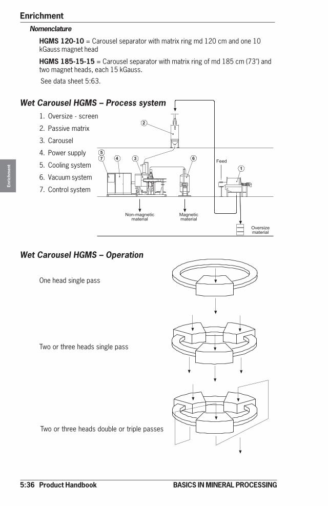
5:36 Product Handbook
EnrichmentEn
rich
men
t
BASICS IN MINERAL PROCESSING
*�-���-�!����!�����
&
#'"$
(
)
��-�!����!�����
�8����9���!�����
%���
Nomenclature
HGMS 120-10 = Carousel separator with matrix ring md 120 cm and one 10kGauss magnet head
HGMS 185-15-15 = Carousel separator with matrix ring of md 185 cm (73") andtwo magnet heads, each 15 kGauss.
Wet Carousel HGMS – Process system1. Oversize - screen
2. Passive matrix
3. Carousel
4. Power supply
5. Cooling system
6. Vacuum system
7. Control system
Wet Carousel HGMS – Operation
One head single pass
Two or three heads single pass
Two or three heads double or triple passes
See data sheet 5:63.
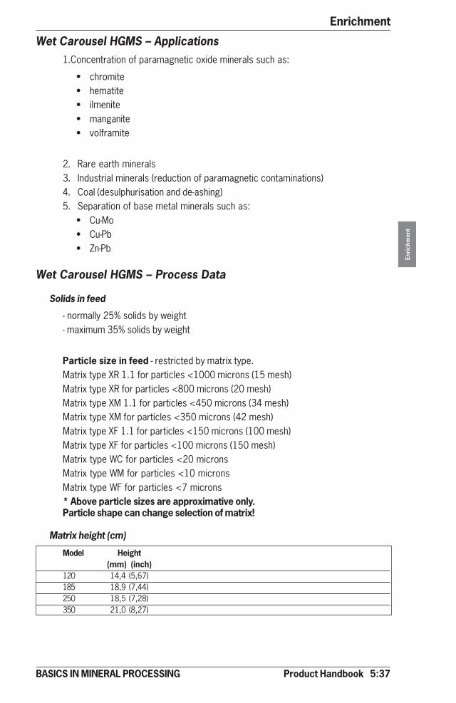
Product Handbook 5:37
Enrichment
Enri
chm
ent
BASICS IN MINERAL PROCESSING
Wet Carousel HGMS – Applications1.Concentration of paramagnetic oxide minerals such as:
• chromite• hematite• ilmenite• manganite• volframite
2. Rare earth minerals3. Industrial minerals (reduction of paramagnetic contaminations)4. Coal (desulphurisation and de-ashing)5. Separation of base metal minerals such as:
• Cu-Mo• Cu-Pb• Zn-Pb
Wet Carousel HGMS – Process Data
Solids in feed
- normally 25% solids by weight- maximum 35% solids by weight
Particle size in feed - restricted by matrix type.Matrix type XR 1.1 for particles <1000 microns (15 mesh)Matrix type XR for particles <800 microns (20 mesh)Matrix type XM 1.1 for particles <450 microns (34 mesh)Matrix type XM for particles <350 microns (42 mesh)Matrix type XF 1.1 for particles <150 microns (100 mesh)Matrix type XF for particles <100 microns (150 mesh)Matrix type WC for particles <20 micronsMatrix type WM for particles <10 micronsMatrix type WF for particles <7 microns* Above particle sizes are approximative only.Particle shape can change selection of matrix!
Matrix height (cm)
Model Height(mm) (inch)
120 14,4 (5,67)185 18,9 (7,44)250 18,5 (7,28)350 21,0 (8,27)
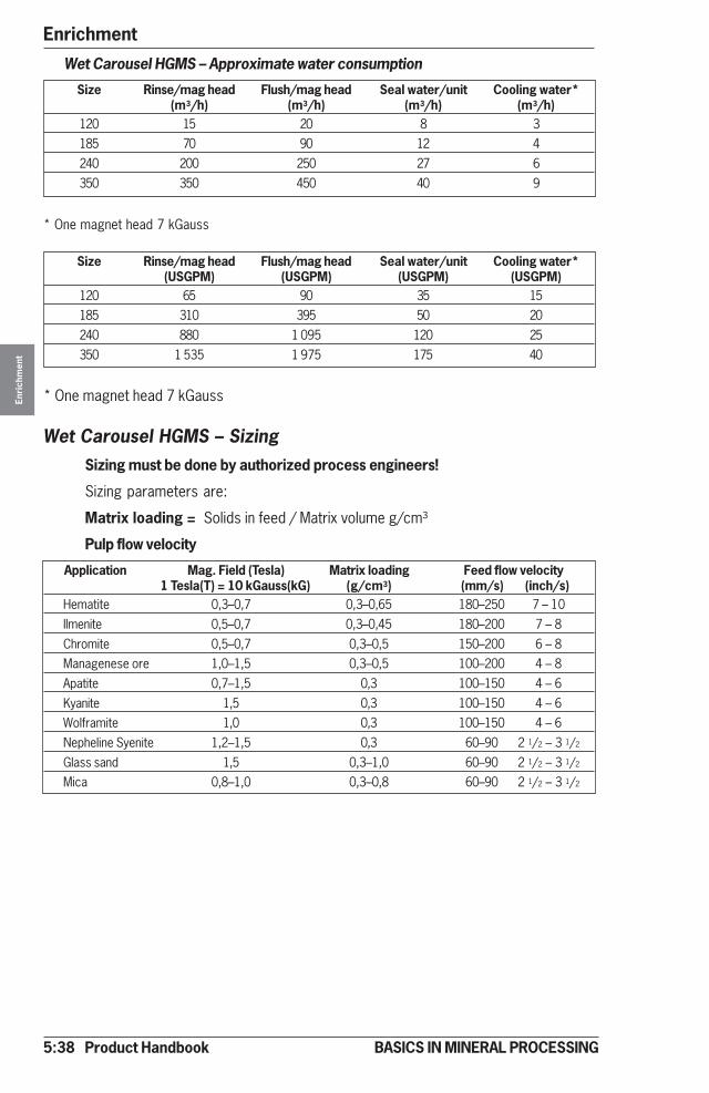
5:38 Product Handbook
EnrichmentEn
rich
men
t
BASICS IN MINERAL PROCESSING
Wet Carousel HGMS – Approximate water consumption
Size Rinse/mag head Flush/mag head Seal water/unit Cooling water*(m3/h) (m3/h) (m3/h) (m3/h)
120 15 20 8 3185 70 90 12 4240 200 250 27 6350 350 450 40 9
* One magnet head 7 kGauss
Size Rinse/mag head Flush/mag head Seal water/unit Cooling water*(USGPM) (USGPM) (USGPM) (USGPM)
120 65 90 35 15185 310 395 50 20240 880 1 095 120 25350 1 535 1 975 175 40
* One magnet head 7 kGauss
Wet Carousel HGMS – SizingSizing must be done by authorized process engineers!
Sizing parameters are:
Matrix loading = Solids in feed / Matrix volume g/cm³
Pulp flow velocity
Application Mag. Field (Tesla) Matrix loading Feed flow velocity1 Tesla(T) = 10 kGauss(kG) (g/cm3) (mm/s) (inch/s)
Hematite 0,3–0,7 0,3–0,65 180–250 7 – 10Ilmenite 0,5–0,7 0,3–0,45 180–200 7 – 8Chromite 0,5–0,7 0,3–0,5 150–200 6 – 8Managenese ore 1,0–1,5 0,3–0,5 100–200 4 – 8Apatite 0,7–1,5 0,3 100–150 4 – 6Kyanite 1,5 0,3 100–150 4 – 6Wolframite 1,0 0,3 100–150 4 – 6Nepheline Syenite 1,2–1,5 0,3 60–90 2 1/2 – 3 1/2
Glass sand 1,5 0,3–1,0 60–90 2 1/2 – 3 1/2
Mica 0,8–1,0 0,3–0,8 60–90 2 1/2 – 3 1/2

Product Handbook 5:39
Enrichment
Enri
chm
ent
BASICS IN MINERAL PROCESSING
High Gradient Magnetic Filter - HGMFA special version of the cyclic HGMS technique, is used to remove magnetic orweakly magnetic particles from liquids.
HGMF – design
The design is very similar to the cyclic HGMS machine however with some specialfeatures
• Robust and compact design• Magnetic gradients up to 20 kG• Canister dia up to 2140 mm (84")• Maximum pressure drop 100 bar (1450 psi)• Allowing high pressure and high temperatures• Large holding capacity in matrix
HGMF - Sizes and Nomenclature
Sizes
7 sizes (industrial units) named from outer diameter (cm) of canister:
Type: 38, 46, 56, 76, 107, 152, 214
Magnetic field intensity available for each size: 3, 5, 10 and 15 kG.
Matrix height: 15, 30 and 50 cm. (0.6", 1.2" and 2") (for water clarification)
Nomenclature
HGMF 56-15-3 = magnetic filter with canister diameter 56 cm, matrix height15 cm and magnetic field intensity 3 kG. See data sheet 5:64.
HGMF - ApplicationsGenerally: For high pressure, high temperature and “lack of space” applications
• Removal of iron and copper particles from boiler circuits• Cleaning of district heating systems• Removal of weakly magnetic particles from process water (mill scale, metal-
lurgical dust etc.)

5:40 Product Handbook
EnrichmentEn
rich
men
t
BASICS IN MINERAL PROCESSING
HGMF – Process DataSolids in feed Normally very low ppm levels
Particle size in feed Restricted by matrix typeMatrix type KF will allow particles - 100 microns
Size Matrix area ft2 Matrix area m2
38 0,8 0,0756 2,0 0,1976 4,6 0,43
107 9,1 0,85152 18,8 1,75214 36,8 3,42
HGMF – SizingSizing similar to conventional clarification sizing, see section 6:3.
Surface load (m3/h and m2) is the flow velocity through the matrix for optimalclarification.
Surface load Surface loadApplication * (m3/ m2, h) (ft3/ft2, min) Flush intervalCondensate polishing 500–1 500 27 - 81 7–21 daysDistrict heating systems 500–1 500 27 - 81 24 hoursSteel mill cooling water 200–800 11 - 44 0.3–1 hours
* Magnetic field 3 kg
Ex 1:
Steel mill cooling water can be treated with a surface load of
500 m3/m2 x h at 3 kG. The flow is 800 m3/h.
Required area 800 / 500 = 1.6 m2
Select HGMF 152 - 15 - 3
Ex 2:
Paper mill Condensate water can be treated with a surface load ofapprox. 500 GPMPSF (Gallon per minute per squarefoot)
Flow is 3000 GPM
HGMF model 107 has an area = 9.1 ft2
3000 / 9.1 = 330 GPMPSF (OK!)

Product Handbook 5:41
Enrichment
Enri
chm
ent
BASICS IN MINERAL PROCESSING
2�:;
2�:
2:;
2:
:;
�:; �� ��< ��� ��= ���
Separation by LeachingWhen mechanical methods of separation cannot secure optimal metal value of anore, leaching is an alternative, either as a complement or as an overall process.Most of the leaching process is feed preparation by crushing, grinding and insome cases pre-concentration and roasting.The separation is normally done by creating retention time for the chemicals topenetrate the feed.
Leaching by methods Typical feed size Typical retention time
Waste dumps leaching -1500 mm (60 inch) 10 yearsHeaps leaching -150 mm (6 inch) 1 yearAgitation leaching (coarse) -200 micron (65 mesh) 2–24 hoursAgitation leaching (fine) - 10 micron 5–10 min
The waste and heap leaching operations are typically low in investment but high incost of chemicals. Recovery is normally low (below 60%).The agitation methods (con current or counter current) are high in investment butare paid back in higher recovery.
Leaching by size
In leaching there is always an optimum in the relation feed size versus recovery.This balance between cost for size reduction and value recovery is important toestablish for high value ores, see below.
-75 micron (200mesh) in feed %
LeachantsType of ore Leachant Typical particle size Typical retention time
Cu ore (oxide) H2SO4 (5.00%) - 9 mm, (3/8 inch) 5 days
Au ore NaCN (0.05%) - 200 micron, 65 mesh 4-24 h
Au conc. (sulphide) NaCN (0.10%) -45 micron, 325 mesh 10-72h
Ilmenite H2SO4 (90.0%) -75 micron, 200 mesh 0.5h
Ni ore (laterite) H2SO4 (3.00%) -150 micron, 100 mesh 2h
Ag ore NaCN (0.20%) -200 micron, 65 mesh 72h
Uranium ore H2SO4 (0.5-5%) -150 micron, 100 mesh 16-48 h
Uranium ore Na2CO3 (5.00%) -150 micron, 100 mesh 90h
Loss
or g
ain
$ pe
r ton

5:42 Product Handbook
EnrichmentEn
rich
men
t
BASICS IN MINERAL PROCESSING
� � � � �
Leaching of MetalsBelow find the flow sheets for classical leaching circuits, heap leaching forcoarse fractions (crushing only) of low grade ores and agitation leaching for finerfraction of high value ores.
In the Heap leaching process the ground is protected by a sealed surface,collecting the leaching chemicals, re- circulated by pumping. When the solution is“pregnant” its clarified by sedimentation or sand filtration and taken to metalrecovery by electrowinning.
In the Agitation leaching circuit the feed is finer (typical –200 microns) and theslurry moves in the same direction as the chemicals (con current flow). In thiscase, the pregnant solution has to be recovered from the solids by mechanicaldewatering due to particle size, see section 6.
minus 20 mmACIDS
LEACHINGSOLUTION
METAL RECOVERYELECTROWINNING
SAND FILTER
minus 0.2 mm
ACIDS
TRASH
METAL RECOVERYELECTROWINNING TAILINGS
AIR PRESSURE FILTER(SOLID/LIQUID SEPARATION)
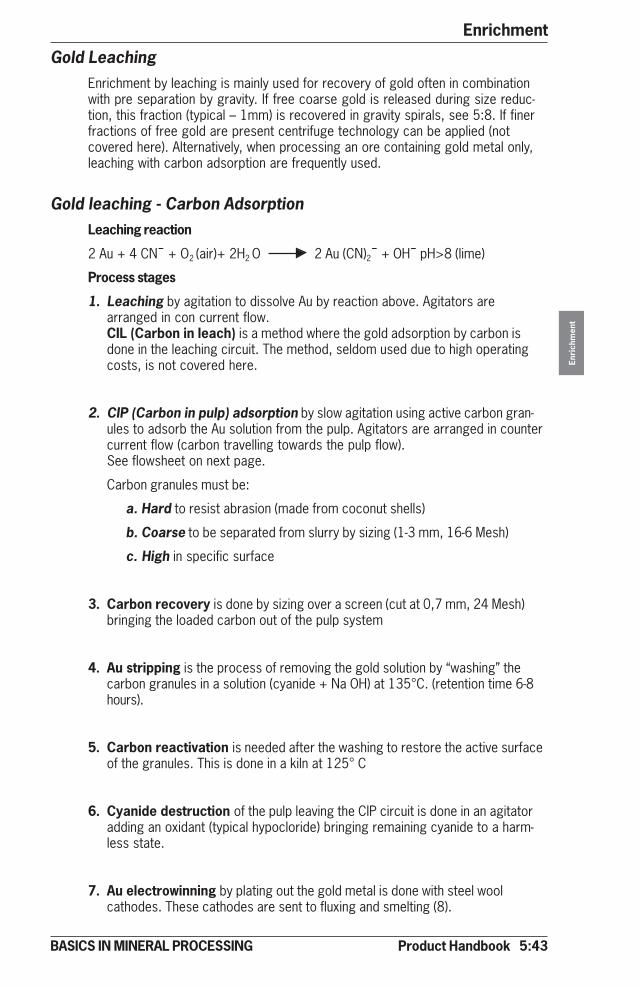
Product Handbook 5:43
Enrichment
Enri
chm
ent
BASICS IN MINERAL PROCESSING
Gold LeachingEnrichment by leaching is mainly used for recovery of gold often in combinationwith pre separation by gravity. If free coarse gold is released during size reduc-tion, this fraction (typical – 1mm) is recovered in gravity spirals, see 5:8. If finerfractions of free gold are present centrifuge technology can be applied (notcovered here). Alternatively, when processing an ore containing gold metal only,leaching with carbon adsorption are frequently used.
Gold leaching - Carbon AdsorptionLeaching reaction
2 Au + 4 CN¯ + O2 (air)+ 2H2 O 2 Au (CN)2¯ + OH¯ pH>8 (lime)
Process stages
1. Leaching by agitation to dissolve Au by reaction above. Agitators arearranged in con current flow.CIL (Carbon in leach) is a method where the gold adsorption by carbon isdone in the leaching circuit. The method, seldom used due to high operatingcosts, is not covered here.
2. CIP (Carbon in pulp) adsorption by slow agitation using active carbon gran-ules to adsorb the Au solution from the pulp. Agitators are arranged in countercurrent flow (carbon travelling towards the pulp flow).See flowsheet on next page.
Carbon granules must be:
a. Hard to resist abrasion (made from coconut shells)
b. Coarse to be separated from slurry by sizing (1-3 mm, 16-6 Mesh)
c. High in specific surface
3. Carbon recovery is done by sizing over a screen (cut at 0,7 mm, 24 Mesh)bringing the loaded carbon out of the pulp system
4. Au stripping is the process of removing the gold solution by “washing” thecarbon granules in a solution (cyanide + Na OH) at 135°C. (retention time 6-8hours).
5. Carbon reactivation is needed after the washing to restore the active surfaceof the granules. This is done in a kiln at 125° C
6. Cyanide destruction of the pulp leaving the CIP circuit is done in an agitatoradding an oxidant (typical hypocloride) bringing remaining cyanide to a harm-less state.
7. Au electrowinning by plating out the gold metal is done with steel woolcathodes. These cathodes are sent to fluxing and smelting (8).
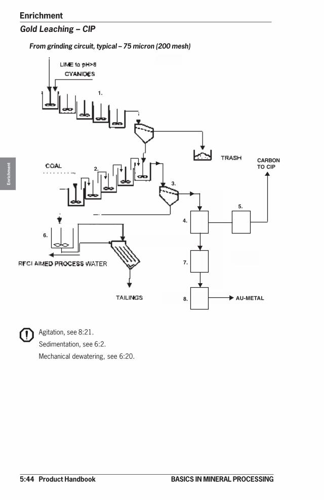
5:44 Product Handbook
EnrichmentEn
rich
men
t
BASICS IN MINERAL PROCESSING
1.
2.
3.
6.
CARBONTO CIP
AU-METAL
4.
5.
7.
8.
Gold Leaching – CIP
From grinding circuit, typical – 75 micron (200 mesh)
Agitation, see 8:21.
Sedimentation, see 6:2.
Mechanical dewatering, see 6:20.
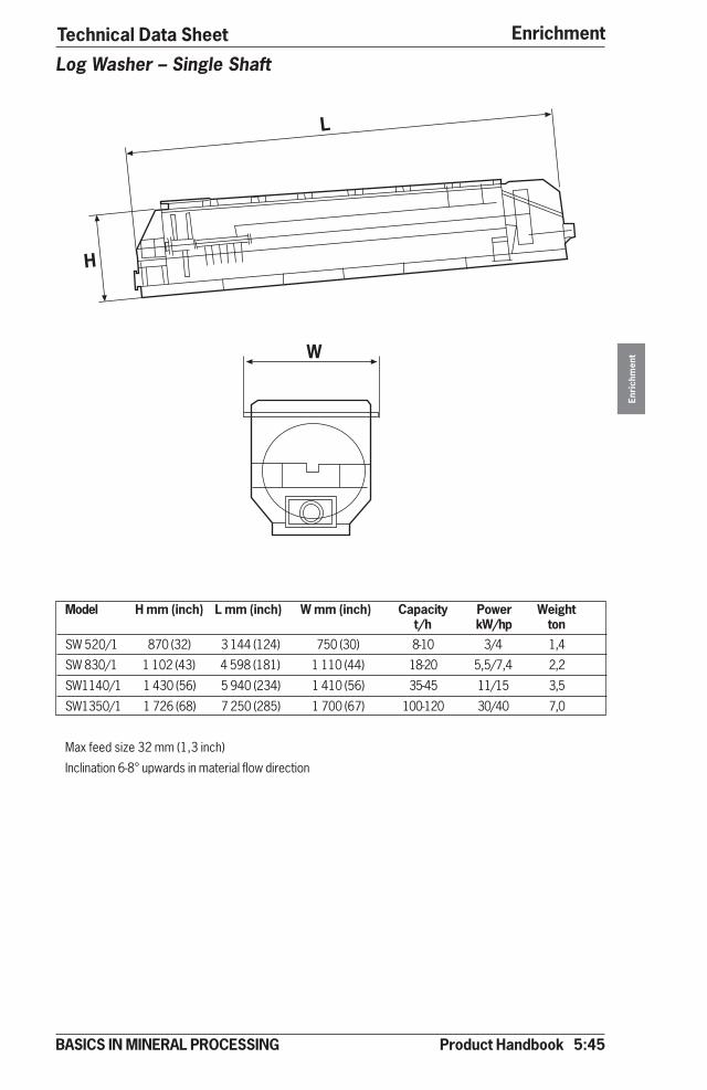
Product Handbook 5:45
Enrichment
Enri
chm
ent
BASICS IN MINERAL PROCESSING
Technical Data Sheet
Model H mm (inch) L mm (inch) W mm (inch) Capacity Power Weightt/h kW/hp ton
SW 520/1 870 (32) 3 144 (124) 750 (30) 8-10 3/4 1,4
SW 830/1 1 102 (43) 4 598 (181) 1 110 (44) 18-20 5,5/7,4 2,2
SW1140/1 1 430 (56) 5 940 (234) 1 410 (56) 35-45 11/15 3,5
SW1350/1 1 726 (68) 7 250 (285) 1 700 (67) 100-120 30/40 7,0
Max feed size 32 mm (1,3 inch)
Inclination 6-8° upwards in material flow direction
Log Washer – Single Shaft
�
�
�
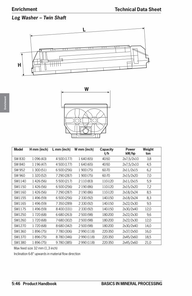
5:46 Product Handbook
EnrichmentEn
rich
men
t
BASICS IN MINERAL PROCESSING
Technical Data Sheet
Model H mm (inch) L mm (inch) W mm (inch) Capacity Power Weightt/h kW/hp ton
SW 830 1 096 (43) 4 500 (177) 1 640 (65) 40-50 2x7,5/2x10 3,8
SW 840 1 196 (47) 4 500 (177) 1 640 (65) 40-50 2x7,5/2x10 4,5
SW 952 1 300 (51) 6 500 (256) 1 900 (75) 60-70 2x11/2x15 6,2
SW 960 1 320 (52) 7 290 (287) 1 900 (75) 60-70 2x15/2x20 7,0
SW1140 1 426 (56) 5 500 (217) 2 110 (83) 110-120 2x11/2x15 5,9
SW1150 1 426 (56) 6 500 (256) 2 190 (86) 110-120 2x15/2x20 7,2
SW1160 1 426 (56) 7 290 (287) 2 190 (86) 110-120 2x18/2x24 8,5
SW1155 1 496 (59) 6 500 (256) 2 330 (92) 140-150 2x18/2x24 8,3
SW1165 1 496 (59) 7 350 (289) 2 330 (92) 140-150 2x22/2x30 9,5
SW1175 1 496 (59) 8 400 (331) 2 330 (92) 140-150 2x30/2x40 12,0
SW1250 1 720 (68) 6 680 (263) 2 500 (98) 180-200 2x22/2x30 9,6
SW1260 1 720 (68) 7 680 (302) 2 500 (98) 180-200 2x22/2x30 12,0
SW1270 1 720 (68) 8 680 (342) 2 500 (98) 180-200 2x30/2x40 14,0
SW1360 1 896 (75) 7 780 (306) 2 990 (118) 220-350 2x37/2x50 16,0
SW1370 1 896 (75) 8 780 (346) 2 990 (118) 220-350 2x45/2x60 18,5
SW1380 1 896 (75) 9 780 (385) 2 990 (118) 220-350 2x45/2x60 21,0
Max feed size 32 mm (1,3 inch)
Inclination 6-8° upwards in material flow direction
Log Washer – Twin Shaft
�
�
�
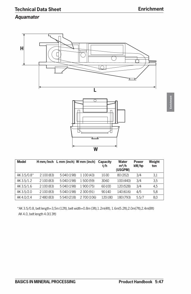
Product Handbook 5:47
Enrichment
Enri
chm
ent
BASICS IN MINERAL PROCESSING
Technical Data SheetAquamator
Model H mm/inch L mm (inch) W mm (inch) Capacity Water Power Weightt/h m³/h kW/hp ton
(USGPM)AK 3.5/0.8* 2 100 (83) 5 040 (198) 1 100 (43) 10-30 80 (352) 3/4 3,1
AK 3.5/1.2 2 100 (83) 5 040 (198) 1 500 (59) 30-60 100 (440) 3/4 3,5
AK 3.5/1.6 2 100 (83) 5 040 (198) 1 900 (75) 60-100 120 (528) 3/4 4,5
AK 3.5/2.0 2 100 (83) 5 040 (198) 2 300 (91) 90-140 140 (616) 4/5 5,8
AK 4.0/2.4 2 480 (83) 5 540 (218) 2 700 (106) 120-180 180 (793) 5.5/7 8,0
*AK 3.5/0.8, belt length=3,5m (12ft), belt width=0.8m (3ft),1.2m(4ft), 1.6m(5.2ft),2.0m(7ft),2.4m(8ft)
AK 4.0, belt length 4.0(13ft)
�
�
�

5:48 Product Handbook
EnrichmentEn
rich
men
t
BASICS IN MINERAL PROCESSING
Technical Data Sheet
Model H mm (inch) L mm (inch) W mm (inch) Capacity Water Power Weightt/h m³/h kW/hp ton
(USGPM)AS 4.0/1.2* 2 230 (88) 5 540 (218) 1 700 (67) 40-80 160 (705) 4/5 3,9
AS 4.0/1.6 2 230 (88) 5 540 (218) 2 100 (83) 80-120 220 (970) 4/5 5,4
AS 4.0/2.0 2 230 (88) 5 540 (218) 2 500 (98) 120-150 300 (1 320) 4/5 6,9
AS 5.0/2.4 3 250 (1289 6 540 (257) 2 900 (114) 150-180 450 (1 981) 7.5/10 11,9
*AS 4.0/1.2, belt length =4.0m(13ft), belt width=1.2m(4ft), 1.6m(5.2ft), 2.0m(7ft), 2.4m (8ft)
AS 5.0, belt length= 5.0m(16ft)
Hydrobelt
�
�
�
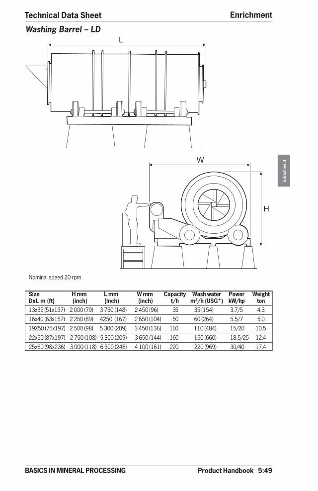
Product Handbook 5:49
Enrichment
Enri
chm
ent
BASICS IN MINERAL PROCESSING
6
1
�
Technical Data Sheet
Washing Barrel – LD
Nominal speed 20 rpm
Size H mm L mm W mm Capacity Wash water Power WeightDxL m (ft) (inch) (inch) (inch) t/h m³/h (USG*) kW/hp ton13x35 (51x137) 2 000 (79) 3 750 (148) 2 450 (96) 35 35 (154) 3.7/5 4.3
16x40 (63x157) 2 250 (89) 4250 (167) 2 650 (104) 50 60 (264) 5.5/7 5.0
19X50 (75x197) 2 500 (98) 5 300 (209) 3 450 (136) 110 110 (484) 15/20 10.5
22x50 (87x197) 2 750 (108) 5 300 (209) 3 650 (144) 160 150 (660) 18.5/25 12.4
25x60 (98x236) 3 000 (118) 6 300 (248) 4 100 (161) 220 220 (969) 30/40 17.4
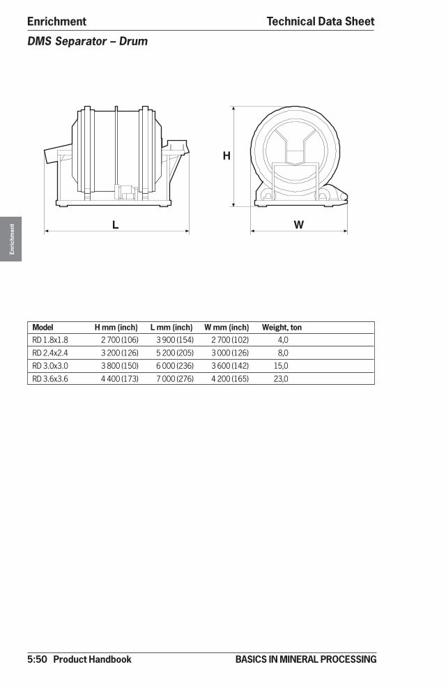
5:50 Product Handbook
EnrichmentEn
rich
men
t
BASICS IN MINERAL PROCESSING
Technical Data Sheet
DMS Separator – Drum
Model H mm (inch) L mm (inch) W mm (inch) Weight, tonRD 1.8x1.8 2 700 (106) 3 900 (154) 2 700 (102) 4,0
RD 2.4x2.4 3 200 (126) 5 200 (205) 3 000 (126) 8,0
RD 3.0x3.0 3 800 (150) 6 000 (236) 3 600 (142) 15,0
RD 3.6x3.6 4 400 (173) 7 000 (276) 4 200 (165) 23,0
WL
H
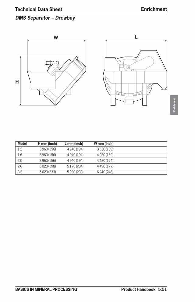
Product Handbook 5:51
Enrichment
Enri
chm
ent
BASICS IN MINERAL PROCESSING
Technical Data Sheet
DMS Separator – Drewboy
Model H mm (inch) L mm (inch) W mm (inch)1.2 3 960 (156) 4 940 (194) 3 530 (139)
1.6 3 960 (156) 4 940 (194) 4 030 (159)
2.0 3 960 (156) 4 940 (194) 4 430 (174)
2.6 5 020 (198) 5 170 (204) 4 490 (177)
3.2 5 620 (233) 5 930 (233) 6 240 (246)
W L
H
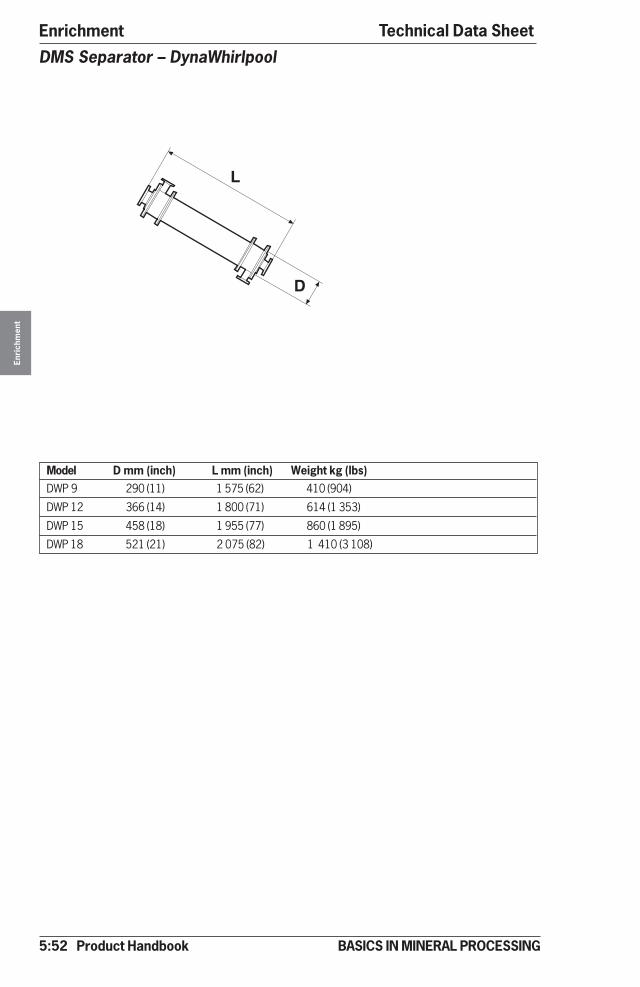
5:52 Product Handbook
EnrichmentEn
rich
men
t
BASICS IN MINERAL PROCESSING
DMS Separator – DynaWhirlpool
Model D mm (inch) L mm (inch) Weight kg (lbs)DWP 9 290 (11) 1 575 (62) 410 (904)
DWP 12 366 (14) 1 800 (71) 614 (1 353)
DWP 15 458 (18) 1 955 (77) 860 (1 895)
DWP 18 521 (21) 2 075 (82) 1 410 (3 108)
Technical Data Sheet
L
D
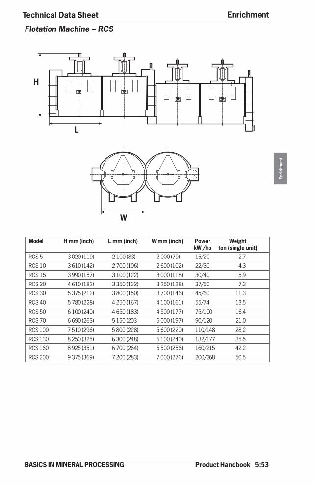
Product Handbook 5:53
Enrichment
Enri
chm
ent
BASICS IN MINERAL PROCESSING
Model H mm (inch) L mm (inch) W mm (inch) Power WeightkW /hp ton (single unit)
RCS 5 3 020 (119) 2 100 (83) 2 000 (79) 15/20 2,7
RCS 10 3 610 (142) 2 700 (106) 2 600 (102) 22/30 4,3
RCS 15 3 990 (157) 3 100 (122) 3 000 (118) 30/40 5,9
RCS 20 4 610 (182) 3 350 (132) 3 250 (128) 37/50 7,3
RCS 30 5 375 (212) 3 800 (150) 3 700 (146) 45/60 11,3
RCS 40 5 780 (228) 4 250 (167) 4 100 (161) 55/74 13,5
RCS 50 6 100 (240) 4 650 (183) 4 500 (177) 75/100 16,4
RCS 70 6 690 (263) 5 150 (203 5 000 (197) 90/120 21,0
RCS 100 7 510 (296) 5 800 (228) 5 600 (220) 110/148 28,2
RCS 130 8 250 (325) 6 300 (248) 6 100 (240) 132/177 35,5
RCS 160 8 925 (351) 6 700 (264) 6 500 (256) 160/215 42,2
RCS 200 9 375 (369) 7 200 (283) 7 000 (276) 200/268 50,5
Flotation Machine – RCS
Technical Data Sheet
�
�
�
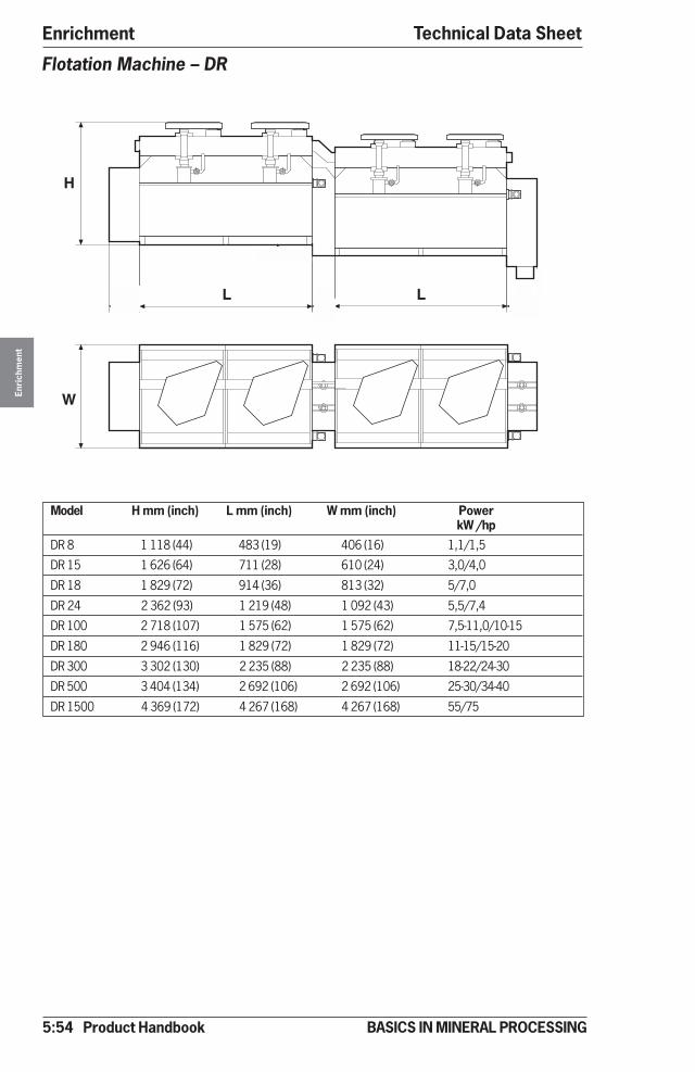
5:54 Product Handbook
EnrichmentEn
rich
men
t
BASICS IN MINERAL PROCESSING
Flotation Machine – DR
Technical Data Sheet
Model H mm (inch) L mm (inch) W mm (inch) PowerkW /hp
DR 8 1 118 (44) 483 (19) 406 (16) 1,1/1,5
DR 15 1 626 (64) 711 (28) 610 (24) 3,0/4,0
DR 18 1 829 (72) 914 (36) 813 (32) 5/7,0
DR 24 2 362 (93) 1 219 (48) 1 092 (43) 5,5/7,4
DR 100 2 718 (107) 1 575 (62) 1 575 (62) 7,5-11,0/10-15
DR 180 2 946 (116) 1 829 (72) 1 829 (72) 11-15/15-20
DR 300 3 302 (130) 2 235 (88) 2 235 (88) 18-22/24-30
DR 500 3 404 (134) 2 692 (106) 2 692 (106) 25-30/34-40
DR 1500 4 369 (172) 4 267 (168) 4 267 (168) 55/75
W
L
H
A B L C
D
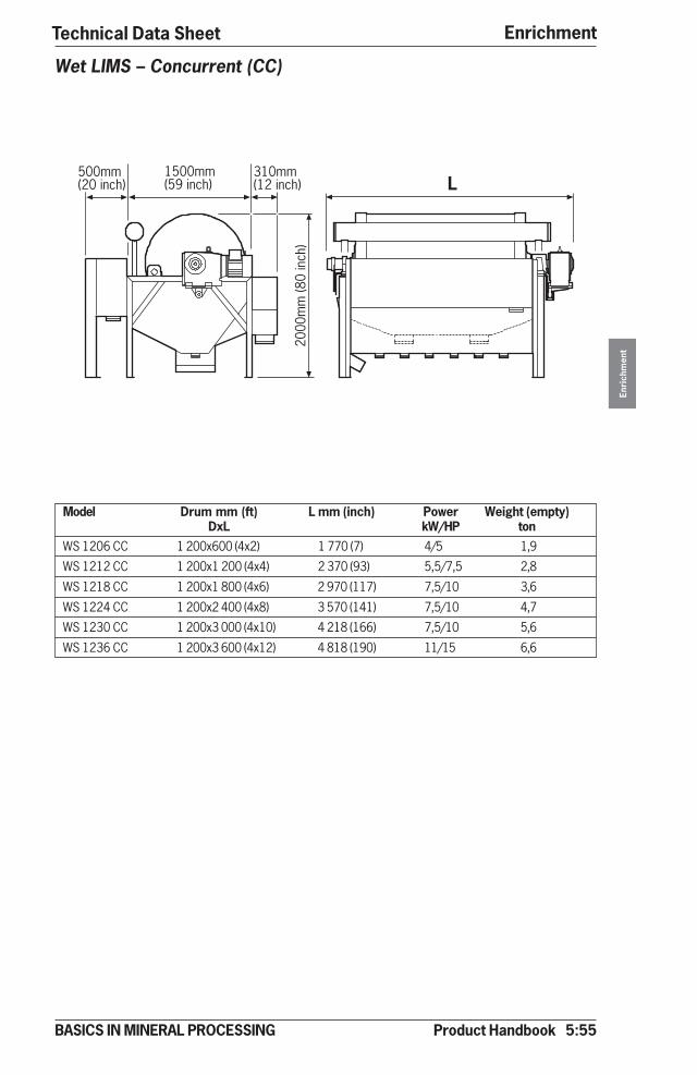
Product Handbook 5:55
Enrichment
Enri
chm
ent
BASICS IN MINERAL PROCESSING
Technical Data Sheet
Wet LIMS – Concurrent (CC)
Model Drum mm (ft) L mm (inch) Power Weight (empty)DxL kW/HP ton
WS 1206 CC 1 200x600 (4x2) 1 770 (7) 4/5 1,9
WS 1212 CC 1 200x1 200 (4x4) 2 370 (93) 5,5/7,5 2,8
WS 1218 CC 1 200x1 800 (4x6) 2 970 (117) 7,5/10 3,6
WS 1224 CC 1 200x2 400 (4x8) 3 570 (141) 7,5/10 4,7
WS 1230 CC 1 200x3 000 (4x10) 4 218 (166) 7,5/10 5,6
WS 1236 CC 1 200x3 600 (4x12) 4 818 (190) 11/15 6,6
������������
�������� ����
������������
����
�����
����
�
�
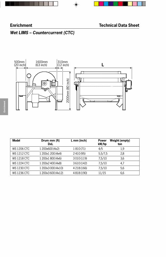
5:56 Product Handbook
Enrichment
Enri
chm
ent
BASICS IN MINERAL PROCESSING
Technical Data Sheet
Model Drum mm (ft) L mm (inch) Power Weight (empty)DxL kW/hp ton
WS 1206 CTC 1 200x600 (4x2) 1 810 (71) 4/5 1,9
WS 1212 CTC 1 200x1 200 (4x4) 2 410 (95) 5,5/7,5 2,8
WS 1218 CTC 1 200x1 800 (4x6) 3 010 (119) 7,5/10 3,6
WS 1224 CTC 1 200x2 400 (4x8) 3 610 (142) 7,5/10 4,7
WS 1230 CTC 1 200x3 000 (4x10) 4 218 (166) 7,5/10 5,6
WS 1236 CTC 1 200x3 600 (4x12) 4 818 (190) 11/15 6,6
Wet LIMS – Countercurrent (CTC)
������������
�������������
������������ �
����
�����
����
�
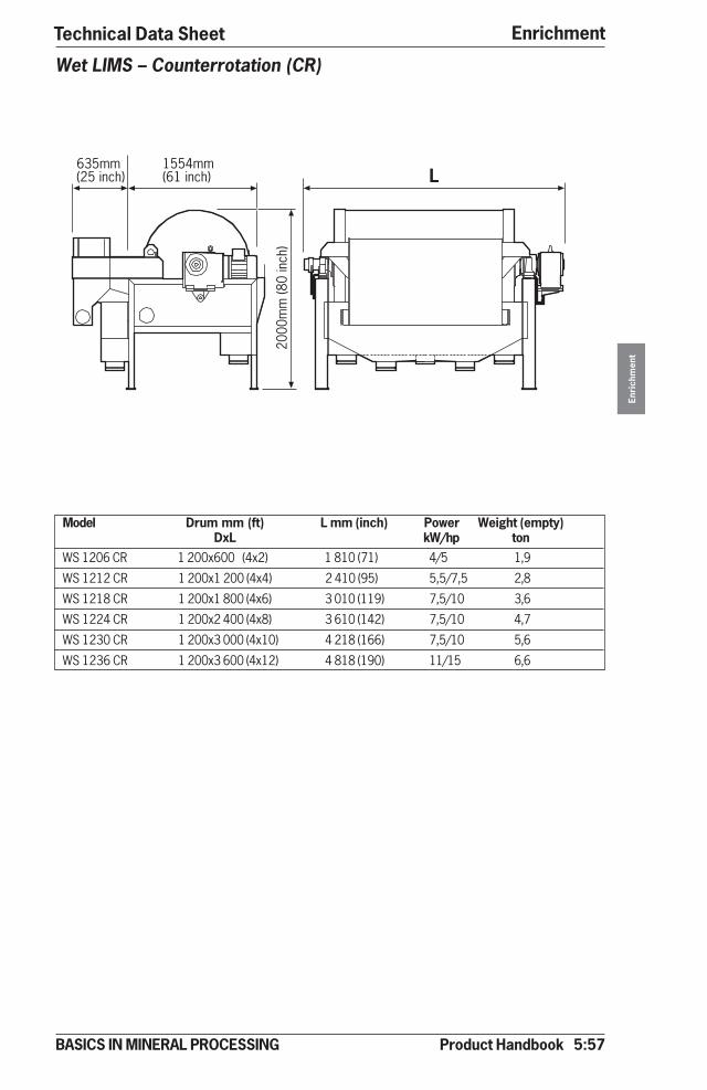
Product Handbook 5:57
Enrichment
Enri
chm
ent
BASICS IN MINERAL PROCESSING
Technical Data Sheet
Wet LIMS – Counterrotation (CR)
Model Drum mm (ft) L mm (inch) Power Weight (empty)DxL kW/hp ton
WS 1206 CR 1 200x600 (4x2) 1 810 (71) 4/5 1,9
WS 1212 CR 1 200x1 200 (4x4) 2 410 (95) 5,5/7,5 2,8
WS 1218 CR 1 200x1 800 (4x6) 3 010 (119) 7,5/10 3,6
WS 1224 CR 1 200x2 400 (4x8) 3 610 (142) 7,5/10 4,7
WS 1230 CR 1 200x3 000 (4x10) 4 218 (166) 7,5/10 5,6
WS 1236 CR 1 200x3 600 (4x12) 4 818 (190) 11/15 6,6
������������
�������������
����
�����
����
�
�
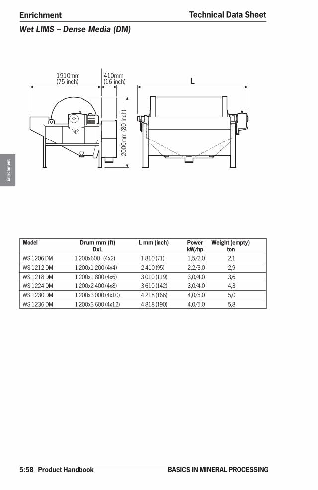
5:58 Product Handbook
EnrichmentEn
rich
men
t
BASICS IN MINERAL PROCESSING
Technical Data Sheet
Model Drum mm (ft) L mm (inch) Power Weight (empty)DxL kW/hp ton
WS 1206 DM 1 200x600 (4x2) 1 810 (71) 1,5/2,0 2,1
WS 1212 DM 1 200x1 200 (4x4) 2 410 (95) 2,2/3,0 2,9
WS 1218 DM 1 200x1 800 (4x6) 3 010 (119) 3,0/4,0 3,6
WS 1224 DM 1 200x2 400 (4x8) 3 610 (142) 3,0/4,0 4,3
WS 1230 DM 1 200x3 000 (4x10) 4 218 (166) 4,0/5,0 5,0
WS 1236 DM 1 200x3 600 (4x12) 4 818 (190) 4,0/5,0 5,8
Wet LIMS – Dense Media (DM)
� �����������
������������
����
�����
����
�
�

Product Handbook 5:59
Enrichment
Enri
chm
ent
BASICS IN MINERAL PROCESSING
Technical Data Sheet
Wet LIMS – Dense Media (DMHG)
Model Drum mm (ft) L mm (inch) Power Weight (empty)DxL kW/hp ton
WS1206 DM 1 200x600 (4x2) 1 810 (71) 1,5/2,0 2,1
WS1212 DM 1 200x1 200 (4x4) 2 410 (95) 2,2/3,0 2,9
WS1218 DM 1 200x1 800 (4x6) 3 010 (119) 3,0/4,0 3,6
WS1224 DM 1 200x2 400 (4x8) 3 610 (142) 3,0/4,0 4,3
WS1230 DM 1 200x3 000 (4x10) 4 218 (166) 4,0/5,0 5,0
WS1236 DM 1 200x3 600 (4x12) 4 818 (190) 4,0/5,0 5,8
� �����������
������������
����
�����
����
�
�
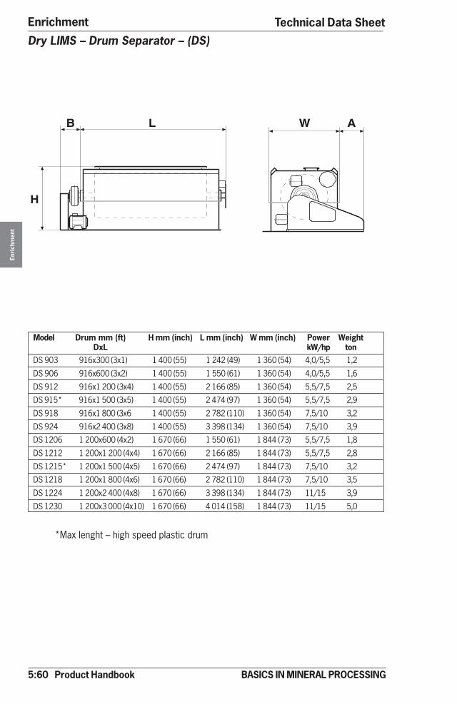
5:60 Product Handbook
EnrichmentEn
rich
men
t
BASICS IN MINERAL PROCESSING
Dry LIMS – Drum Separator – (DS)
Model Drum mm (ft) H mm (inch) L mm (inch) W mm (inch) Power WeightDxL kW/hp ton
DS 903 916x300 (3x1) 1 400 (55) 1 242 (49) 1 360 (54) 4,0/5,5 1,2
DS 906 916x600 (3x2) 1 400 (55) 1 550 (61) 1 360 (54) 4,0/5,5 1,6
DS 912 916x1 200 (3x4) 1 400 (55) 2 166 (85) 1 360 (54) 5,5/7,5 2,5
DS 915* 916x1 500 (3x5) 1 400 (55) 2 474 (97) 1 360 (54) 5,5/7,5 2,9
DS 918 916x1 800 (3x6 1 400 (55) 2 782 (110) 1 360 (54) 7,5/10 3,2
DS 924 916x2 400 (3x8) 1 400 (55) 3 398 (134) 1 360 (54) 7,5/10 3,9
DS 1206 1 200x600 (4x2) 1 670 (66) 1 550 (61) 1 844 (73) 5,5/7,5 1,8
DS 1212 1 200x1 200 (4x4) 1 670 (66) 2 166 (85) 1 844 (73) 5,5/7,5 2,8
DS 1215* 1 200x1 500 (4x5) 1 670 (66) 2 474 (97) 1 844 (73) 7,5/10 3,2
DS 1218 1 200x1 800 (4x6) 1 670 (66) 2 782 (110) 1 844 (73) 7,5/10 3,5
DS 1224 1 200x2 400 (4x8) 1 670 (66) 3 398 (134) 1 844 (73) 11/15 3,9
DS 1230 1 200x3 000 (4x10) 1 670 (66) 4 014 (158) 1 844 (73) 11/15 5,0
*Max lenght – high speed plastic drum
Technical Data Sheet
H
L AB W
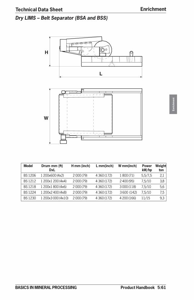
Product Handbook 5:61
Enrichment
Enri
chm
ent
BASICS IN MINERAL PROCESSING
Model Drum mm (ft) H mm (inch) L mm(inch) W mm(inch) Power WeightDxL kW/hp ton
BS 1206 1 200x600 (4x2) 2 000 (79) 4 360 (172) 1 800 (71) 5,5/7,5 2,1
BS 1212 1 200x1 200 (4x4) 2 000 (79) 4 360 (172) 2 400 (95) 7,5/10 3,8
BS 1218 1 200x1 800 (4x6) 2 000 (79) 4 360 (172) 3 000 (118) 7,5/10 5,6
BS 1224 1 200x2 400 (4x8) 2 000 (79) 4 360 (172) 3 600 (142) 7,5/10 7,5
BS 1230 1 200x3 000 (4x10) 2 000 (79) 4 360 (172) 4 200 (166) 11/15 9,3
Dry LIMS – Belt Separator (BSA and BSS)
Technical Data Sheet
H
W
L

5:62 Product Handbook
EnrichmentEn
rich
men
t
BASICS IN MINERAL PROCESSING
Wet Cyclic HGMS
Model H mm (ft) L mm (ft) W mm (ft) Power Weight Matrix area(magnet) (empty)
kW ton m² (ft²)38-15-10* 4 000 (13) 3 800 (12) 2 450 (8) 40 10 0,11 (1,18)
56-15-10 4 100 (13) 4 000 (13) 2 450 (8) 46 13 0,19 (2,05)
76-15-10 4 100 (13) 4 200 (14) 2 450 (8) 53 14 0,43 (4,63)
107-15-10 4 380 (14) 5 150 (17) 2 900 (10) 63 26 0,85 (9,15)
152-15-10 ** ** ** 80 46 1,75 (18,84)
214-15-10 ** ** ** 103 ** 3,42 (36,81)
305-15-10 ** ** ** - ** 7,30 (78,58)
*38-15-10= 38(Outer diameter in cm)-15(matrix height in cm)-10 (field rating in kGauss)
Magnetic field available 5,10,15 and 20 kGauss
** Site specific
Technical Data Sheet
H
W
L
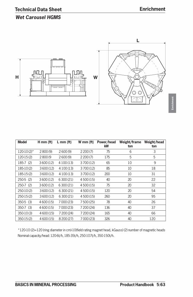
Product Handbook 5:63
Enrichment
Enri
chm
ent
BASICS IN MINERAL PROCESSING
Wet Carousel HGMS
Model H mm (ft) L mm (ft) W mm (ft) Power/head Weight/frame Weight/headkW ton ton
120-10 (2)* 2 800 (9) 2 600 (9) 2 200 (7) 75 6 3
120-15 (2) 2 800 (9 2 600 (9) 2 200 (7) 175 5 5
185-7 (2) 3 600 (12) 4 100 (13) 3 700 (12) 65 10 9
185-10 (2) 3 600 (12) 4 100 (13) 3 700 (12) 85 10 18
185-15 (2) 3 600 (12) 4 100 (13) 3 700 (12) 200 10 31
250-5 (2) 3 600 (12) 6 300 (21) 4 500 (15) 40 20 22
250-7 (2) 3 600 (12) 6 300 (21) 4 500 (15) 75 20 32
250-10 (2) 3 600 (12) 6 300 (21) 4 500 (15) 120 20 54
250-15 (2) 3 600 (12) 6 300 (21) 4 500 (15) 260 20 95
350-5 (3) 4 600 (15) 7 000 (23) 7 500 (25) 78 40 26
350-7 (3) 4 600 (15) 7 000 (23) 7 200 (24) 136 40 37
350-10 (3) 4 600 (15) 7 200 (24) 7 200 (24) 165 40 66
350-15 (2) 4 600 (15) 8 200 (27) 7 000 (23) 326 40 120
*120-10 (2)=120 (ring diameter in cm)-10(field rating magnet head, kGauss) (2) number of magnetic heads
Nominal capacity/head: 120-6t/h, 185-35t/h, 250-107t/h, 350-150t/h.
Technical Data Sheet
W
L
H
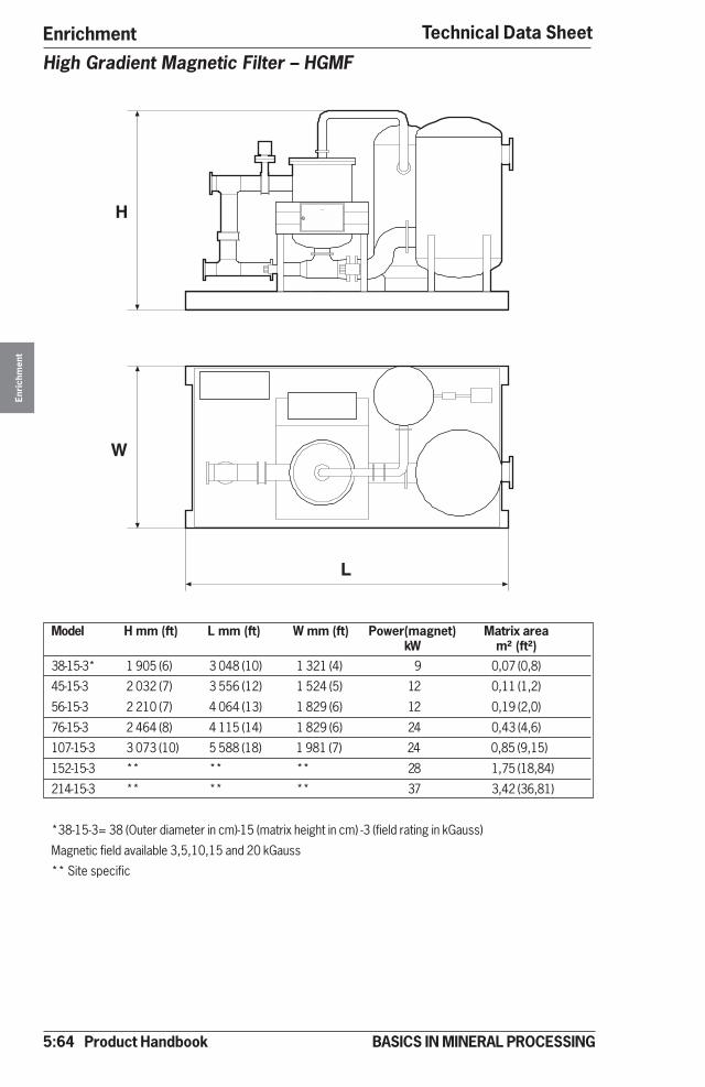
5:64 Product Handbook
EnrichmentEn
rich
men
t
BASICS IN MINERAL PROCESSING
High Gradient Magnetic Filter – HGMF
Technical Data Sheet
Model H mm (ft) L mm (ft) W mm (ft) Power(magnet) Matrix areakW m² (ft²)
38-15-3* 1 905 (6) 3 048 (10) 1 321 (4) 9 0,07 (0,8)
45-15-3 2 032 (7) 3 556 (12) 1 524 (5) 12 0,11 (1,2)
56-15-3 2 210 (7) 4 064 (13) 1 829 (6) 12 0,19 (2,0)
76-15-3 2 464 (8) 4 115 (14) 1 829 (6) 24 0,43 (4,6)
107-15-3 3 073 (10) 5 588 (18) 1 981 (7) 24 0,85 (9,15)
152-15-3 ** ** ** 28 1,75 (18,84)
214-15-3 ** ** ** 37 3,42 (36,81)
*38-15-3= 38 (Outer diameter in cm)-15 (matrix height in cm) -3 (field rating in kGauss)
Magnetic field available 3,5,10,15 and 20 kGauss
** Site specific
W
L
H

Product Handbook 6:1
Upgrading
Upg
radi
ng
BASICS IN MINERAL PROCESSING
Upgrading – IntroductionWith upgrading we understand, the further processing of the final products fromthe enrichment stages in a process.This is valid both concerning the valuable minerals (the concentrate) and the wasteminerals (the tailings).
In the first case upgrading means improving the product value by bringing theconcentrate to transportability or into a completely dry form. Processing can alsogo further to calcining and sintering.On the tailing side upgrading means that waste material (wash water, processeffluents etc.) is properly taken care of in order to protect the environment, torecover process water and to turn certain portions into valueables.
Upgrading by methodsSedimentation Mechanical DewateringClarification/Thickening (Conventional) GravityClarification/Thickening (Compact) Low Pressure
Medium PressureHigh Pressure
Thermal drying Thermal processingDirect CalciningIndirect Sintering (pelletizing)
Upgrading by operation costsUpgrading has its price, increasing with the energy input for removal of theprocess water (or process liquid).
The curves above must always be considered when we are selecting equipmentfor an upgrading circuit for concentrate drying or disposal of a washing effluent.The rules are simple!
1. Can we do the job with sedimentation only? If not - how far can we reach bysedimentation thereby saving money in the following dewatering stage?
2. How far can we reach with mechanical dewatering? Can we save a thermalstage by increasing the dewatering pressure?
3. If the particles are coarse, can gravity dewatering do the job? The cost isclose to the same as for sedimentation.
4. If thermal dewatering is needed, can energy be saved in drying by improvedmechanical dewatering?
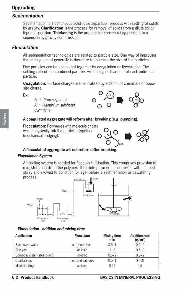
6:2 Product Handbook
UpgradingU
pgra
ding
BASICS IN MINERAL PROCESSING
FlocculationAll sedimentation technologies are related to particle size. One way of improvingthe settling speed generally is therefore to increase the size of the particles.
Fine particles can be connected together by coagulation or flocculation. Thesettling rate of the combined particles will be higher than that of each individualparticle.
Coagulation: Surface charges are neutralized by addition of chemicals of oppo-site charge.
Ex:Fe+++ (iron sulphate)Al+++ (aluminium sulphate)Ca++ (lime)
A coagulated aggregate will reform after breaking (e.g. pumping).
Flocculation: Polymeres with molecule chainswhich physically link the particles together(mechanical bridging).
A flocculated aggregate will not reform after breaking.Flocculation System
A handling system is needed for flocculant utilisation. This comprises provision tomix, store and dilute the polymer. The dilute polymer is then mixed with the feedslurry and allowed to condition (or age) before a sedimentation or dewateringprocess.
Flocculation - addition and mixing time
Application Flocculant Mixing time Addition ratemin (g/m3)
Sand wash water an- or non-ionic 0,5 - 1 0,5 - 5Flue gas an-ionic 1 - 3 0,5 - 2Scrubber water (steel plant) an-ionic 0,5 - 2 0,5 - 2Coal tailings non- and cat.ionic 0,5 - 1 2 - 10Mineral tailings an-ionic 0,5-1 1-5
SedimentationSedimentation is a continuous solid-liquid separation process with settling of solidsby gravity. Clarification is the process for removal of solids from a dilute solid/liquid suspension. Thickening is the process for concentrating particles in asupension by gravity compression

Product Handbook 6:3
Upgrading
Upg
radi
ng
BASICS IN MINERAL PROCESSING
Conventional ClarifierClarification is achieved when the liquid “upstream” velocity VL is lower than thesedimentation velocity of the solids VS
Example
A wash water (100 m3/h) coming from a sand operation needs to be clarified.Surface load is 0,5 m3/h/m2. Select clarifier diameter.
Required area is: 100/0,5 = 200 m2= �d2
= 200 where d is required diameter= 15,9. 4
Select a 16 m clarification tank!
Note! When thickening is also a critical part of the sedimentation process, the tankdiameter has to be cross-checked with the diameter for thickener duty, see nextpage.
Conventional Clarifier – sizingClarifier diameter is selected to give a suitable upstream velocity (m/h). This isalso expressed as “Surface Load”, meaning the volume of slurry m3/h fed per m2
of clarifier surface. Typical surface areas are given below.
Surface load Surface load Surface loadMaterial Feed % (m3/m2, h) (ft3/ft2, min)Brine purification 0,1-2 0,5-1,2 0,03-0,07Coal refuse 0,5-6 0,7-1,7 0,04-0,09Clean coal fines - 1,0-1,9 0,06-0,10Heavy media magnetite 20-30 6-7,5 0,32-0,41Flue dust, blast furnace 0,2-2 1,5-3,7 0,08-0,20Flue dust, BOF 0,2-2 1,0-1,7 0,06-0,09Magnesium oxide 0,5 0,6-1,2 0,03-0,07 (with flocculation)Foundry waste water 1,0 0,7-1,0 0,04-0,06 (with flocculation)Plating waste 2-5 1,2 0.07Green liquor 0,2 0,8 0.04Gypsum desulphurization 1-3 1-2 0,06-0,12Sand wash water 1-5 0,3-1 0,02-0,06 (without flocculation)
1-5 1-4 0,06-0,22 (with flocculation)Ore flotation tailings 10-20 0,1-0,3 0,005-0,02 (without flocculation)
10-20 0,5-1,5 0,03-0,08 (with flocculation)

6:4 Product Handbook
UpgradingU
pgra
ding
BASICS IN MINERAL PROCESSING
Conventional ThickenerContinuous thickening to give the required solids concentration in the underflowdepends on balancing the volumetric solids flow rate at a critical concentrationwith the diameter of the thickener.
Conventional Thickeners – SizingThickener selection is based upon the unit area, defined as m2 of thickener arearequired per tph of solids. Typical figures for unit area are given below.
Feed UnderflowSolids Solids Unit Area
Application (% w/w) (% w/w) (m2 / (t/h) (ft2/st x 24h)Ni-conc k80 35 µm 27 65 3,5 1,6Apatite conc k70 74 µm 27 60 10,5 5Calcite conc k80 180 µm 30 60 0,07 0,03Bauxite k25 100 µm 10 40 420 188Phosphate conc k80 60 µm 18 70 25 11Tailings sulphide ores k80 90 µm 40 57 7 3Tailings iron ores k80 70 µm 12 50 60 27
Molybdenum concentrate 10 30 20-35 9-16Fe-conc k80 130 µm 30 75 4 2Pyrite k80 40µm 19 65 26 11,5Cu-conc k80 80 µm 40 75 2 1Zn-conc k80 90 µm 20 68 0,7 0,3Pb-conc 20-25 60-80 15-30 6,5-13
Clarification/ thickening – cross checking (metric)
Clarification and thickening are process definitions. The equipment can be appliedto both duties. If this is the case we have to select the tank area for each dutyand select the largest of the two.
Ex: Cu concentrate (k80= 80 µm), 10 t/h or 18m³/h
Surface load (with flocculation) = 1.5 m/hUnit area = 2 m²/(t/h)Clarification area = 18/ 1.5 = 12 m²Thickening area = 10x2 = 20 m²Select a Clarifier / Thickener of 20m² , diameter 5 m.
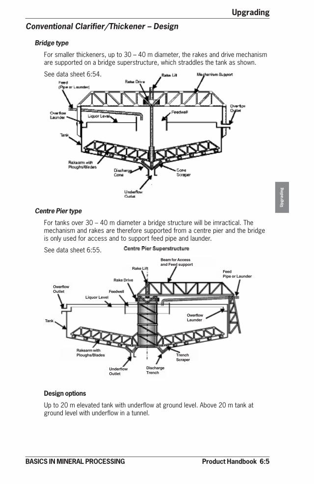
Product Handbook 6:5
Upgrading
Upg
radi
ng
BASICS IN MINERAL PROCESSING
Conventional Clarifier/Thickener – Design
Bridge type
For smaller thickeners, up to 30 – 40 m diameter, the rakes and drive mechanismare supported on a bridge superstructure, which straddles the tank as shown.
See data sheet 6:54.
Centre Pier type
For tanks over 30 – 40 m diameter a bridge structure will be imractical. Themechanism and rakes are therefore supported from a centre pier and the bridgeis only used for access and to support feed pipe and launder.
See data sheet 6:55.
Design options
Up to 20 m elevated tank with underflow at ground level. Above 20 m tank atground level with underflow in a tunnel.
OwerflowOutlet
Liquor LevelFeedwell
Rake Drive
Rake Lift
Beam for Accessand Feed support
FeedPipe or Launder
Tank
Rakearm withPloughs/Blades
UnderflowOutlet
DischargeTrench
TrenchScraper
OwerflowLaunder
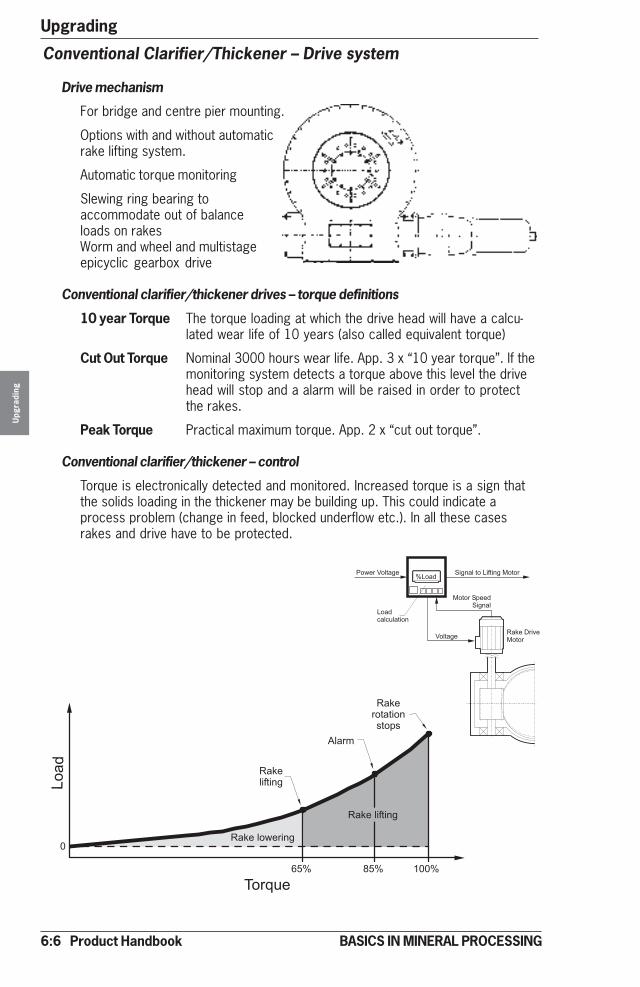
6:6 Product Handbook
UpgradingU
pgra
ding
BASICS IN MINERAL PROCESSING
Conventional Clarifier/Thickener – Drive system
Drive mechanism
For bridge and centre pier mounting.
Options with and without automaticrake lifting system.
Automatic torque monitoring
Slewing ring bearing toaccommodate out of balanceloads on rakesWorm and wheel and multistageepicyclic gearbox drive
Conventional clarifier/thickener drives – torque definitions
10 year Torque The torque loading at which the drive head will have a calcu-lated wear life of 10 years (also called equivalent torque)
Cut Out Torque Nominal 3000 hours wear life. App. 3 x “10 year torque”. If themonitoring system detects a torque above this level the drivehead will stop and a alarm will be raised in order to protectthe rakes.
Peak Torque Practical maximum torque. App. 2 x “cut out torque”.
Conventional clarifier/thickener – control
Torque is electronically detected and monitored. Increased torque is a sign thatthe solids loading in the thickener may be building up. This could indicate aprocess problem (change in feed, blocked underflow etc.). In all these casesrakes and drive have to be protected.
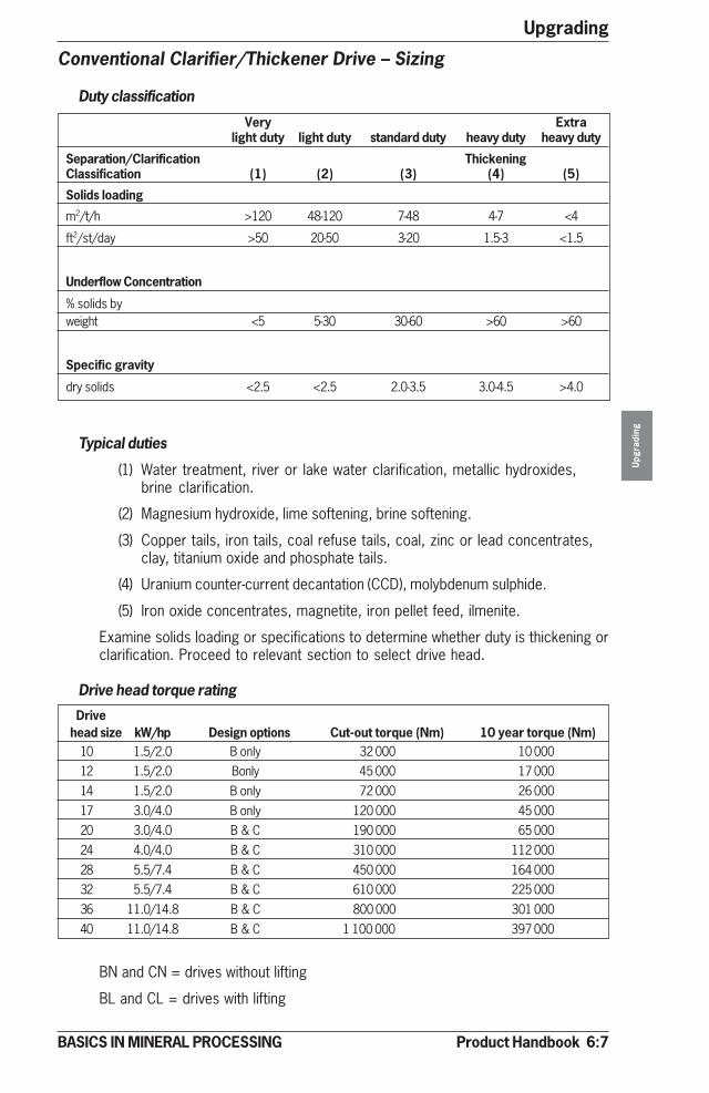
Product Handbook 6:7
Upgrading
Upg
radi
ng
BASICS IN MINERAL PROCESSING
Conventional Clarifier/Thickener Drive – Sizing
Duty classification
Very Extralight duty light duty standard duty heavy duty heavy duty
Separation/Clarification ThickeningClassification (1) (2) (3) (4) (5)
Solids loading
m2/t/h >120 48-120 7-48 4-7 <4
ft2/st/day >50 20-50 3-20 1.5-3 <1.5
Underflow Concentration
% solids byweight <5 5-30 30-60 >60 >60
Specific gravity
dry solids <2.5 <2.5 2.0-3.5 3.0-4.5 >4.0
Typical duties
(1) Water treatment, river or lake water clarification, metallic hydroxides,brine clarification.
(2) Magnesium hydroxide, lime softening, brine softening.
(3) Copper tails, iron tails, coal refuse tails, coal, zinc or lead concentrates,clay, titanium oxide and phosphate tails.
(4) Uranium counter-current decantation (CCD), molybdenum sulphide.
(5) Iron oxide concentrates, magnetite, iron pellet feed, ilmenite.
Examine solids loading or specifications to determine whether duty is thickening orclarification. Proceed to relevant section to select drive head.
Drive head torque rating
Drivehead size kW/hp Design options Cut-out torque (Nm) 10 year torque (Nm)
10 1.5/2.0 B only 32 000 10 00012 1.5/2.0 Bonly 45 000 17 00014 1.5/2.0 B only 72 000 26 00017 3.0/4.0 B only 120 000 45 00020 3.0/4.0 B & C 190 000 65 00024 4.0/4.0 B & C 310 000 112 00028 5.5/7.4 B & C 450 000 164 00032 5.5/7.4 B & C 610 000 225 00036 11.0/14.8 B & C 800 000 301 00040 11.0/14.8 B & C 1 100 000 397 000
BN and CN = drives without lifting
BL and CL = drives with lifting

6:8 Product Handbook
UpgradingU
pgra
ding
BASICS IN MINERAL PROCESSING
Clarifier drive selection
Clarifiers, see duty page 6:8, operate with a low solids loading and drives areselected according to formula below
Tc = KxD2
Tc = Process Cut Off torque (Nm)
K = Clarifier duty factor (see below)
D = Clarifier Diameter (m)
Duty factor
Clarifying application Duty factorBrine purification 60Lime softening 80Metal hydroxides 150Magnesium hydroxide (sea water) 185Rolling Mill water 190Lime sludge 210Calcium carbonate 210Pulp and paper sludge 250Pickle liquors and rinse water 255Plating waste 255Blast furnace dust 320Oxygen furnace dust 350Heat treatment (metal) sludge 440
Select a drive head from the” Drive Head Torque” values above, so that thespecified “cut out torque” is greater then calculated Tc.
Example: Select a bridge mounted drive head for a 35 m diameter clarifier (nolift required). Application: lime sludge clarifying.
K factor = 210 giving a Tc = 210 x 35² = 257 250 Nm. Select a drive head typeBN 24, cut out torque 310 000Nm.
Thickener drive selection
Here we are calculating with Process Equivalent Torque (or 10 year torque), seepage 6:8, according to formula
Te = 256 x D x √MTe = Process Equivalent Torque
D = Thickener diameter (m)
M = Solids in underflow (tph), see duty above
Select a drive head from the “Drive Head Torque” values above, so that the 10year torque is greater than Te calculated above.
Example: Select a pier mounted drive head with a lift suitable for a 50 m diam-eter thickener handling an underflow of 130 tph of solids.
Te = 256x50x√130 = 145 952 Nm. Select CL 28 drive head with a 10 year torqueof 164 000 Nm.

Product Handbook 6:9
Upgrading
BASICS IN MINERAL PROCESSING
Conventional Clarifier/Thickener – AreasDiameter Area Diameter Area
(m) (ft) (m2) (ft2) (m) (ft) (m2) (ft2)10 33 78 839 38 125 1 134 12 20612 39 113 1 216 40 131 1 257 13 53014 46 154 1 658 42 138 1 385 14 91316 52 201 2 164 44 144 1 521 16 36718 59 254 2 734 46 151 1 662 17 88920 66 314 3 380 48 157 1 810 19 47922 72 380 4 090 50 164 1 963 21 13024 79 452 4 865 52 170 2 124 22 86026 85 531 5 716 54 177 2 290 24 65328 92 616 6 631 56 184 2 463 26 51230 98 706 7 599 58 190 2 642 28 44032 105 804 8 654 60 197 2 827 30 43034 111 908 9 77336 118 1 018 10 958
Conventional Clarifier/Thickener – Tank DepthThickener dia (m) Tank depths Standard (centre) Minimum (centre)
(m) (ft) (m) (ft)3.5 – 5.5 2,4 7,9 2,3 7,56.0 – 15 3,0 9,8 2,7 8,916 – 23 3,6 11,8 3,0 9,824 – 26 4,6 15,1 4,3 14,127 – 38 5,2 17,0 4,9 16,138 – 42 5,5 18,0 4,9 16,143 – 46 5,8 19,0 5,2 17,047 – 49 7,0 23,0 5,8 19,050 – 52 7,3 24,0 6,4 21,053 – 55 7,6 25,0 6,7 22,0
Use minimum depth if feed volume flow rate is less than 1.2 m3/m2,h.
Conventional Clarifier/Thickener – Tank Bottom SlopeApplication Tank slope (mm/m) DegreesFine particle sediments 80 5Metallurgical sludges 145 8 (standard slope)Coarse and or heavy particles 200 11
For small thickeners no slope restrictions (up to 45o).
For larger diameter thickeners (>dia 45 m) a two-slope tank is recommended forheight saving reasons. Inner 1/3 (9 o) out 2/3 (5 o)
Slope for 1/3 of dia 165 mm/m (9 degrees)
Slope for 2/3 dia (outer) 80 mm/m (5 degrees)See also data sheet 6:54 - 55.

6:10 Product Handbook
UpgradingU
pgra
ding
BASICS IN MINERAL PROCESSING
Lamella or Inclined PlateSedimentation – Introduction
“By tilting a clarifier to an angle of55° we have a lamella clarifier witha new relation between solids andliquids, compared to a conventionalclarifier”.
By a combination of a short dis-tance of sedimentation and “frictionfree sliding” the separation speedis increased.
Clarification is achieved whenupstream velocity is low enough toallow solids to report to the“Lamella plate”.
Clarification is not achieved whenupstream velocity is too high andsolids will not report to the “lamellaplate”.
Lamella thickening is achieved asprimary thickening (1) on the lamellaplates and secondary thickening (2)(conventional) in the lamella tank.
1
2
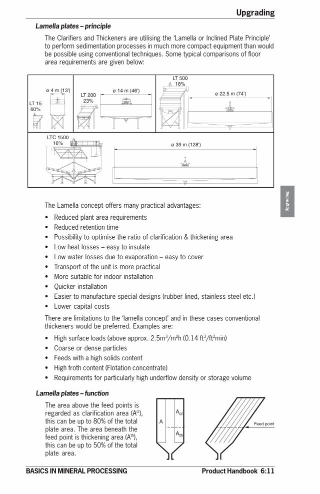
Product Handbook 6:11
Upgrading
Upg
radi
ng
BASICS IN MINERAL PROCESSING
Lamella plates – principle
The Clarifiers and Thickeners are utilising the ‘Lamella or Inclined Plate Principle’to perform sedimentation processes in much more compact equipment than wouldbe possible using conventional techniques. Some typical comparisons of floorarea requirements are given below:
The Lamella concept offers many practical advantages:
• Reduced plant area requirements• Reduced retention time• Possibility to optimise the ratio of clarification & thickening area• Low heat losses – easy to insulate• Low water losses due to evaporation – easy to cover• Transport of the unit is more practical• More suitable for indoor installation• Quicker installation• Easier to manufacture special designs (rubber lined, stainless steel etc.)• Lower capital costs
There are limitations to the ‘lamella concept’ and in these cases conventionalthickeners would be preferred. Examples are:
• High surface loads (above approx. 2.5m3/m2h (0.14 ft3/ft2min)• Coarse or dense particles• Feeds with a high solids content• High froth content (Flotation concentrate)• Requirements for particularly high underflow density or storage volume
Lamella plates – function
The area above the feed points isregarded as clarification area (Acl),this can be up to 80% of the totalplate area. The area beneath thefeed point is thickening area (Ath),this can be up to 50% of the totalplate area.

6:12 Product Handbook
UpgradingU
pgra
ding
BASICS IN MINERAL PROCESSING
Inclined Plate Settler
Design
The Inclined Plate Settler consists of two main components, the upper tankcontaining the lamella plates inclined at 55° and the lower conical or cylindricalsludge container.
The feed for the Inclined Plate Settler enters through vertical chambers on eitherside of the lamella packs and passes into each plate gap through slotted feedports. Clarification takes place above the suspension inlet so there is no mixing ofthe clarified fluid with the incoming feed.
Above each pack is a full-length overflow launder fitted with throttling holes tocreate a slight hydraulic back pressure on the incoming feed stream. This methodof feed control guarantees equal distribution to all lamella chambers with minimumturbulence at the entry points.
The solids settle onto and slide down each lamella plate to the sludge containerwhere the solids are further thickened and compressed with the assistance of theraking system.
1. Feed inlet
2. Flocculation chamber
3. Lamella plate packs
4. Overflow launders
5. Overflow outlet
6. Sludge hopper
7. Underflow outlet
8. Rake with drive unit
9. Flocculation agitator
4
5
6
7
1
92
3
8

Product Handbook 6:13
Upgrading
Upg
radi
ng
BASICS IN MINERAL PROCESSING
Inclined Plate Settler – Drives
Design
1. Gear motor2. Planetary gear3. Screw jack4. Frame
Sizes
Max. operating Cut-out Power LiftingDrive unit torque torque range capacitysize (Nm) (ft lbs) (Nm) (ft lbs) (kW) (hp) (kN) (lbf)SFL 02 2 000 1 475 2 700 1 990 0,18-0,75 1/4-1 50 11 2400SFL 05 5 000 3 690 6 750 5 000 0,37-2,2 1/2-3 50 11 2400SFL 10 10 000 7 380 13 500 9 956 0,37-5,5 1/2-71/2 50 11 2400SFL 20 20 000 14 760 27 000 19 900 0,55-4,0 3/4-5 50 11 2400
SFL 30 30 000 22 140 40 500 29 900 0,75-5,5 1-71/2 50 11 2400
SFL 60 60 000 44 255 80 000 59 005 0,75-5,5 1-71/2 100 22 4800
Lifting sequences
Definition: 100% load equal to max torque recommendedby supplier.
Load Function
< 50% Normal operation with rakes in lower position.
> 75% Rakes are lifted until 100% load is reached. Rakesstay in upper position until 70% is reached, thenlowering towards bottom position.
> 100% Cut-out torque stops rotation of rakes. Lifting tothe top position and alarm. Starts up normallyfrom drive head control panel.Control panel
• PLC controlled• Fully automatic incl. functions for:
Speed control of flocculatorTorque signalStart and stop sequencesAlarm indications for levels, flows etc.Control of underflow valve and pump
1 1
2
3
2
3
4
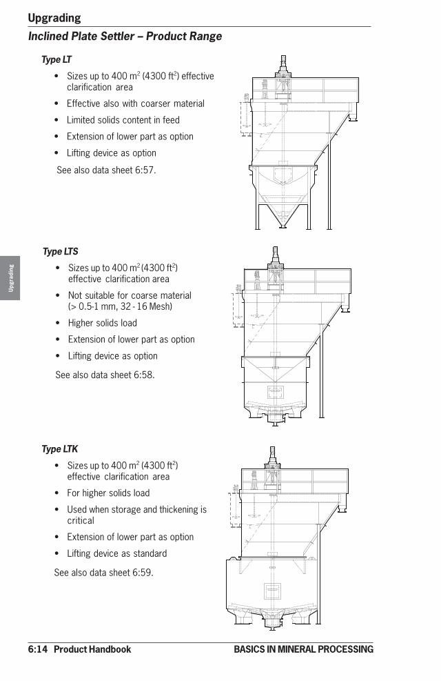
6:14 Product Handbook
UpgradingU
pgra
ding
BASICS IN MINERAL PROCESSING
Inclined Plate Settler – Product Range
Type LT
• Sizes up to 400 m2 (4300 ft2) effectiveclarification area
• Effective also with coarser material
• Limited solids content in feed
• Extension of lower part as option
• Lifting device as option
Type LTS
• Sizes up to 400 m2 (4300 ft2)effective clarification area
• Not suitable for coarse material(> 0.5-1 mm, 32 - 16 Mesh)
• Higher solids load
• Extension of lower part as option
• Lifting device as option
Type LTK
• Sizes up to 400 m2 (4300 ft2)effective clarification area
• For higher solids load
• Used when storage and thickening iscritical
• Extension of lower part as option
• Lifting device as standard
See also data sheet 6:57.
See also data sheet 6:58.
See also data sheet 6:59.
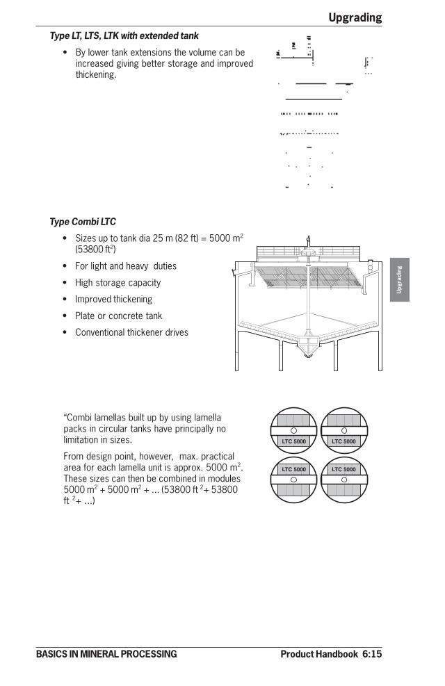
Product Handbook 6:15
Upgrading
Upg
radi
ng
BASICS IN MINERAL PROCESSING
Type LT, LTS, LTK with extended tank
• By lower tank extensions the volume can beincreased giving better storage and improvedthickening.
Type Combi LTC
• Sizes up to tank dia 25 m (82 ft) = 5000 m2
(53800 ft2)
• For light and heavy duties
• High storage capacity
• Improved thickening
• Plate or concrete tank
• Conventional thickener drives
“Combi lamellas built up by using lamellapacks in circular tanks have principally nolimitation in sizes.
From design point, however, max. practicalarea for each lamella unit is approx. 5000 m2.These sizes can then be combined in modules5000 m2 + 5000 m2 + ... (53800 ft 2+ 53800ft 2+ ...)

6:16 Product Handbook
UpgradingU
pgra
ding
BASICS IN MINERAL PROCESSING
�
�
���
Type LTE/C
• Similar to LTE above.
• Conical bottom for denserunderflow.
• Improved access to underflowvalves, pump and piping.
See also data sheet 6:60.
Type LTE
• Sizes up to 1 040 m2 (11 194 ft2)sedimentation area.
• Increased solids storagecapacity for installation prior toa batch process such as a filterpress.
See also data sheet 6:59.
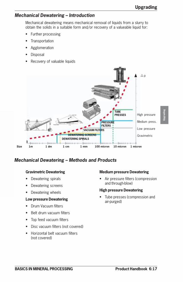
Product Handbook 6:17
Upgrading
Upg
radi
ng
BASICS IN MINERAL PROCESSING
PRESSUREFILTERS
VACUUM FILTERS
TUBEPRESSES
DEWATERING SCREENSDEWATERING SPIRALS
Size 1m 1 dm 1 cm 1 mm 100 micron 10 micron 1 micron
Mechanical Dewatering – IntroductionMechanical dewatering means mechanical removal of liquids from a slurry toobtain the solids in a suitable form and/or recovery of a valueable liquid for:
• Further processing
• Transportation
• Agglomeration
• Disposal
• Recovery of valuable liquids
Mechanical Dewatering – Methods and Products
Medium pressure Dewatering
• Air pressure filters (compressionand through-blow)
High pressure Dewatering
• Tube presses (compression andair-purged)
High pressure
Medium press.
Low pressure
Gravimetric
p
Gravimetric Dewatering
• Dewatering spirals
• Dewatering screens
• Dewatering wheels
Low pressure Dewatering
• Drum Vacuum filters
• Belt drum vacuum filters
• Top feed vacuum filters
• Disc vacuum filters (not covered)
• Horizontal belt vacuum filters(not covered)
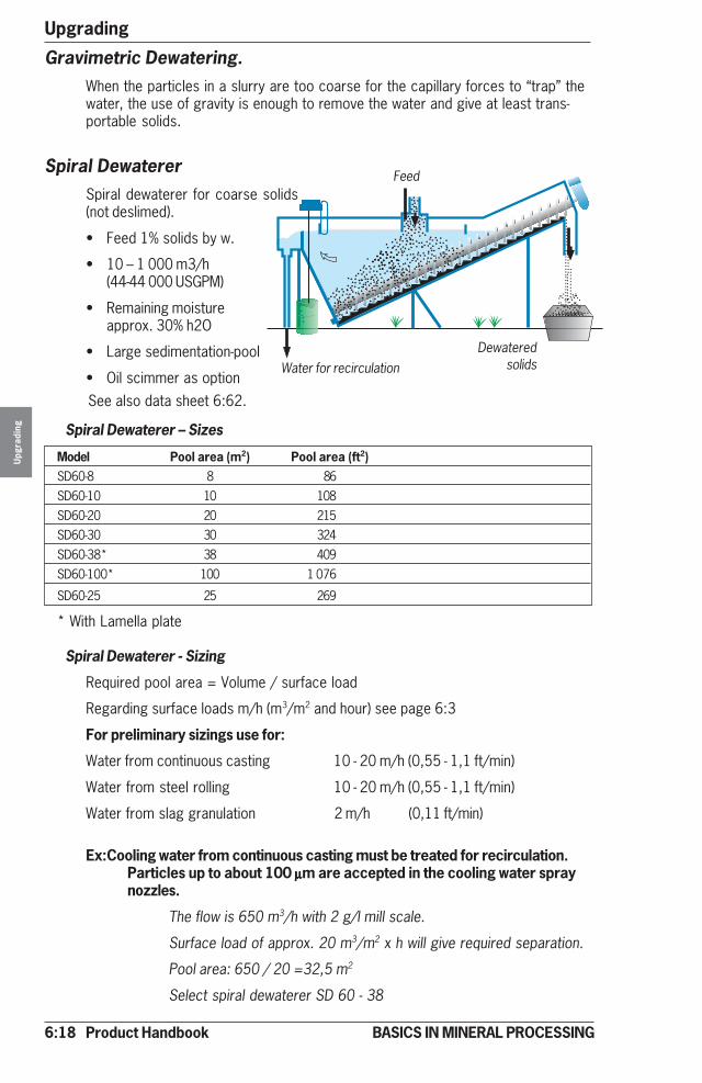
6:18 Product Handbook
UpgradingU
pgra
ding
BASICS IN MINERAL PROCESSING
����� ��
�
�� ���� �����
��������� �
�� ����
�� ���� �����
��������� �
�� ���
�
�� ���� �����
��������� �
�� ���
�
�� ���� �����
��������� �
�� ���
�
�� ���� �����
������ ��� ���
�
�� ���� �����
��������� �
�� ����
�� ���� �����
��������� �
�� ����
�� ���� �����
��������� �
�� ���
�
�� ���� �����
��������� �
�� ���
�
�� ���� �����
��������� �
�� ��� ��� ���� �����
��������� �
�� ��
�
�� ���� �����
�������� �
��
����
� ���
��� � �� ��� ��� �� ��
� ��
�
�� ���� �����
��������� �
�� ���
�
�� ���� �����
��������� �
�� ���
����� �
���
���
�������
��
���
��� ���� �
��� ����� �� �
� ����
����
�� ��
���
���
���
���
��������������������������� ���������
��������� ������������������
���������������������������������������������������������������������
��� ��������
������ ��������� ������ ������������ ���
������
Spiral Dewaterer – Sizes
Model Pool area (m2) Pool area (ft2)SD60-8 8 86SD60-10 10 108SD60-20 20 215SD60-30 30 324SD60-38* 38 409SD60-100* 100 1 076
SD60-25 25 269
* With Lamella plate
Spiral Dewaterer - Sizing
Required pool area = Volume / surface load
Regarding surface loads m/h (m3/m2 and hour) see page 6:3
For preliminary sizings use for:
Water from continuous casting 10 - 20 m/h (0,55 - 1,1 ft/min)
Water from steel rolling 10 - 20 m/h (0,55 - 1,1 ft/min)
Water from slag granulation 2 m/h (0,11 ft/min)
Ex:Cooling water from continuous casting must be treated for recirculation.Particles up to about 100 µµµµµm are accepted in the cooling water spraynozzles.
The flow is 650 m3/h with 2 g/l mill scale.
Surface load of approx. 20 m3/m2 x h will give required separation.
Pool area: 650 / 20 =32,5 m2
Select spiral dewaterer SD 60 - 38
Gravimetric Dewatering.When the particles in a slurry are too coarse for the capillary forces to “trap” thewater, the use of gravity is enough to remove the water and give at least trans-portable solids.
Spiral DewatererSpiral dewaterer for coarse solids(not deslimed).
• Feed 1% solids by w.
• 10 – 1 000 m3/h(44-44 000 USGPM)
• Remaining moistureapprox. 30% h2O
• Large sedimentation-pool
• Oil scimmer as option
Feed
Water for recirculationDewatered
solids
See also data sheet 6:62.
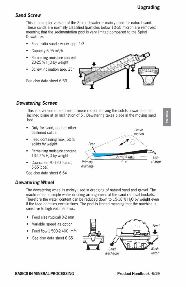
Product Handbook 6:19
Upgrading
Upg
radi
ng
BASICS IN MINERAL PROCESSING
Sand ScrewThis is a simpler version of the Spiral dewaterer mainly used for natural sand.These sands are normally classified (particles below 10-50 micron are removed)meaning that the sedimentation pool is very limited compared to the SpiralDewaterer.
• Only for sand, coal or otherdeslimed solids
• Feed containing max. 50 %solids by weight
• Remaining moisture content13-17 % H2O by weight
• Capacities 70-190 (sand),5-55 (coal)
Dewatering ScreenThis is a version of a screen in linear motion moving the solids upwards on aninclined plane at an inclination of 5o. Dewatering takes place in the moving sandbed.
Dewatering WheelThe dewatering wheel is mainly used in dredging of natural sand and gravel. Themachine has a simple water draining arrangement at the sand removal buckets.Therefore the water content can be reduced down to 15-18 % H2O by weight evenif the feed contains certain fines. The pool is limited meaning that the machine issensitive to high volume flows.
• Feed size (typical) 0-2 mm
• Variable speed as option
• Feed flow 1 500-2 400 m3h
• See also data sheet 6:65
• Feed ratio sand : water app. 1:3
• Capacity 6-95 m3/h
• Remaining moisture content20-25 % H2O by weight
• Screw inclination app. 25o
See also data sheet 6:63.
Feed
Sanddischarge
Washwater
Primarydrainage
Feed
Linearmotion
Dis-charge
Dewatering
See also data sheet 6:64
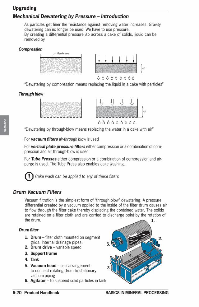
6:20 Product Handbook
UpgradingU
pgra
ding
BASICS IN MINERAL PROCESSING
For vacuum filters air-through blow is used
For vertical plate pressure filters either compression or a combination of com-pression and air through-blow is used
For Tube Presses either compression or a combination of compression and air-purge is used. The Tube Press also enables cake washing.
Drum Vacuum FiltersVacuum filtration is the simplest form of “through blow” dewatering. A pressuredifferential created by a vacuum applied to the inside of the filter drum causes airto flow through the filter cake thereby displacing the contained water. The solidsare retained on a filter cloth and are carried to discharge point by the rotation ofthe drum.
Drum filter
1. Drum – filter cloth mounted on segmentgrids. Internal drainage pipes.
2. Drum drive – variable speed3. Support frame4. Tank5. Vacuum head – seal arrangement
to connect rotating drum to stationaryvacuum piping
6. Agitator – to suspend solid particles in tank
Mechanical Dewatering by Pressure – IntroductionAs particles get finer the resistance against removing water increases. Gravitydewatering can no longer be used. We have to use pressure.By creating a differential pressure ∆p across a cake of solids, liquid can beremoved by
Compression
“Dewatering by compression means replacing the liquid in a cake with particles”
Through blow
“Dewatering by through-blow means replacing the water in a cake with air”
1.
2.
3.
4.
5.
6.
Cake wash can be applied to any of these filters

Product Handbook 6:21
Upgrading
Upg
radi
ng
BASICS IN MINERAL PROCESSING
Belt Drum Filter
The belt discharge drum filter issimilar to the standard drumversion except that the cloth isseparated from the drum andallowed to pass over a dischargesystem.This design allows cloth washingand is preferred for dewatering ofslurries containing fine particleswhich produce a filter cake that issticky and difficult to discharge.Three cake discharge options areavailable.
Drum Vacuum Filters – Effective AreaA practical aspect of Vacuum Drum Filter design is that there is a “dead area” onthe drum between the discharge point and where the drum re-enters the slurry inthe tank. The effective area is always less than the total area as listed below
Drum filter effective area 75% of totalBelt Drum Filter effective area 65% of totalTop Feed Drum Filter effective area 50% of total
Note!
When sizing vacuum filter note that in this book filtration rates area based oncapacity per effective filter area.
When considering data from other sources it must be confirmed whether the“effective” or” total” area is being used!
Top Feed Drum Filter
A top feed drum filter is designed todewater slurries containing coarserparticles.The Top feed principle promotessegregation of the coarser parti-cles forming a “pre –coat” on thefilter cloth thereby increasingfiltration rate.
Break roller Air knife Break roller and air knife
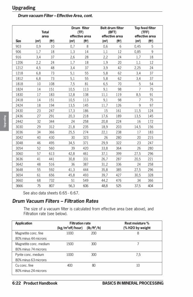
6:22 Product Handbook
UpgradingU
pgra
ding
BASICS IN MINERAL PROCESSING
Drum fliter Belt drum filter Top feed filterTotal (TF) (BFT) (TFF)area effective area effective area effective area
Size (m2) (ft2) (m2) (ft2) (m2) (ft2) (m2) (ft2)903 0,9 10 0,7 8 0,6 6 0,45 5906 1,7 18 1,3 14 1,1 12 0,85 9916 3,4 37 2,6 28 2,2 24 1,7 181206 2,2 24 1,7 18 1,9 20 1,1 121212 4,5 48 3,4 37 3,9 42 2,25 241218 6,8 73 5,1 55 5,8 62 3,4 371812 6,8 73 5,1 55 5,8 62 3,4 371818 10 108 7,5 81 6,5 70 5 541824 14 151 10,5 113 9,1 98 7 751830 17 183 12,8 138 11,1 119 8,5 912418 14 151 10,5 113 9,1 98 7 752424 18 194 13,5 145 11,7 126 9 972430 23 247 17,3 186 15 161 11,5 1242436 27 291 20,3 218 17,6 189 13,5 1452442 32 344 24 258 20,8 224 16 1723030 29 312 21,8 235 18,9 203 14,5 1563036 34 366 25,5 274 22,1 238 17 1833042 40 430 30 323 26 280 20 2153048 46 495 34,5 371 29,9 322 23 2473054 52 560 39 420 33,8 364 26 2803060 57 613 42,8 461 37,1 399 27,5 2963636 41 441 30,8 331 26,7 287 20,5 2213642 48 516 36 387 31,2 336 24 2583648 55 592 41,3 444 35,8 385 27,5 2963654 61 656 45,8 493 39,7 427 30,5 3283660 68 732 51 549 44,2 476 34 3663666 75 807 56,3 606 48,8 525 37,5 404
Drum vacuum Filter – Effective Area, cont.
Drum Vacuum Filters – Filtration RatesThe size of a vacuum filter is calculated from effective area (see above), andFiltration rate (see below).
Application Filtration rate Rest moisture %(kg/m2eff/hour) (lb/ft2/h) (% H2O by weight
Magnetite conc. fine 1000 200 880% minus 44 micronsMagnetite conc. medium 1500 300 780% minus 74 micronsPyrite conc. medium 1000 300 7,580% minus 63 micronsCu conc. fine 400 80 1080% minus 24 microns
See also data sheets 6:65 - 6:67.
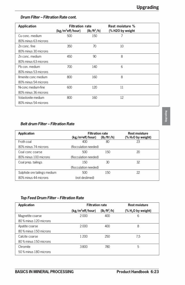
Product Handbook 6:23
Upgrading
Upg
radi
ng
BASICS IN MINERAL PROCESSING
Application Filtration rate Rest moisture %(kg/m2eff/hour) (lb/ft2/h) (% H2O by weight
Cu conc. medium 500 150 780% minus 63 micronsZn conc. fine 350 70 1080% minus 30 micronsZn conc. medium 450 90 880% minus 63 micronsPb con. medium 700 140 680% minus 53 micronsIlmenite conc medium 800 160 880% minus 54 micronsNi-conc medium-fine 600 120 1180% minus 36 micronsVolastonite medium 800 160 1280% minus 54 microns
Drum Filter – Filtration Rate cont.
Belt drum Filter – Filtration Rate
Application Filtration rate Rest moisture(kg/m2eff/hour) (lb/ft2/h) (% H2O by weight)
Froth coal 400 80 2380% minus 74 microns (flocculation needed)Coal conc coarse 500 150 2080% minus 100 microns (flocculation needed)Coal prep. tailings 150 30 32
(flocculation needed)Sulphide ore tailings medium 500 150 2280% minus 44 microns (not deslimed)
Top Feed Drum Filter – Filtration Rate
Application Filtration rate Rest moisture
(kg/m2eff/hour) (lb/ft2/h) (% H2O by weight)Magnetite coarse 2 000 400 680 % minus 120 micronsApatite coarse 2 000 400 880 % minus 150 micronsCalcite coarse 1 200 250 7,580 % minus 150 micronsChromite 3 800 780 550 % minus 180 microns
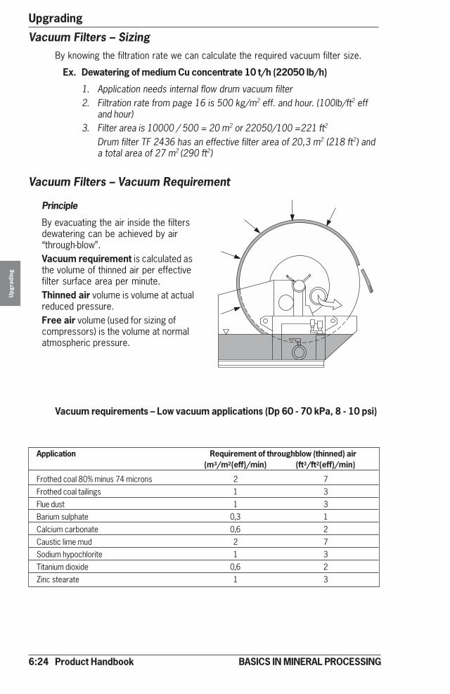
6:24 Product Handbook
UpgradingU
pgra
ding
BASICS IN MINERAL PROCESSING
Vacuum Filters – SizingBy knowing the filtration rate we can calculate the required vacuum filter size.
Ex. Dewatering of medium Cu concentrate 10 t/h (22050 lb/h)
1. Application needs internal flow drum vacuum filter2. Filtration rate from page 16 is 500 kg/m2 eff. and hour. (100lb/ft2 eff
and hour)3. Filter area is 10000 / 500 = 20 m2 or 22050/100 =221 ft2
Drum filter TF 2436 has an effective filter area of 20,3 m2 (218 ft2) anda total area of 27 m2 (290 ft2)
Vacuum Filters – Vacuum Requirement
Principle
By evacuating the air inside the filtersdewatering can be achieved by air“through-blow”.Vacuum requirement is calculated asthe volume of thinned air per effectivefilter surface area per minute.Thinned air volume is volume at actualreduced pressure.Free air volume (used for sizing ofcompressors) is the volume at normalatmospheric pressure.
Vacuum requirements – Low vacuum applications (Dp 60 - 70 kPa, 8 - 10 psi)
Application Requirement of throughblow (thinned) air(m3/m2(eff)/min) (ft3/ft2(eff)/min)
Frothed coal 80% minus 74 microns 2 7Frothed coal tailings 1 3Flue dust 1 3Barium sulphate 0,3 1Calcium carbonate 0,6 2Caustic lime mud 2 7Sodium hypochlorite 1 3Titanium dioxide 0,6 2Zinc stearate 1 3

Product Handbook 6:25
Upgrading
Upg
radi
ng
BASICS IN MINERAL PROCESSING
Vacuum requirement - High vacuum applications (∆∆∆∆∆p 80 - 90 kPa, 12 - 13 psi)
Requirement of throughblow (thinned) airApplication (m3/m2(eff)/min) (ft3/ft2(eff)/min)Magnetite conc fine 80% minus 44 microns 3 10Magnetite conc medium 80% minus 74 microns 4 13Pyrite conc medium 80% minus 63 microns 4 13Cu conc fine 80% minus 24 microns 2 7Cu-conc medium 80% minus 63 microns 4 13Zn-conc fine 80% minus 30 microns 2 7Zn-conc medium 80% minus 63 micron 4 13Pb-conc medium 80% minus 53 microns 3 10Ilmenite conc medium 80% minus 54 microns 3 10Ni-conc fine 80% minus 36 microns 2 7Volastonite conc medium 80% minus 54 microns 3 10Magnetite coarse 8 26Apatite coarse 6 20Calcite coarse 6 20Chromite 8 26
Vacuum Pump - SizingBy multiplying the effective area of the vacuum filter required with the require-ments of throughblow (thinned) air we have the required capacity of thevacuum pump.Ex. Drum filter with effective area of 3,4 m2 and a required vacuum of 1,5 m3/m2/min needs a vacuum pump with a capacity of 3,4 x 1,5 = 5,1 m3/min.
Selection of pump(For our estimations we will use Nash data.)
High vacuum pumpsLow vacuum pumps
Capa
city
thin
ned
air m
3 /m
in
Capa
city
thin
ned
air m
3 /m
in 444
252
172
144
96
54
3723
11.5
kW*
444
288
186
156
78
59
28
14
kW*
36
kPaabsolute pressurekPa
* kW refers to installed motor power. For low vacuum pumps at 35 kPa and forhigh vacuum pumps at 20 kPa absolute pressure.
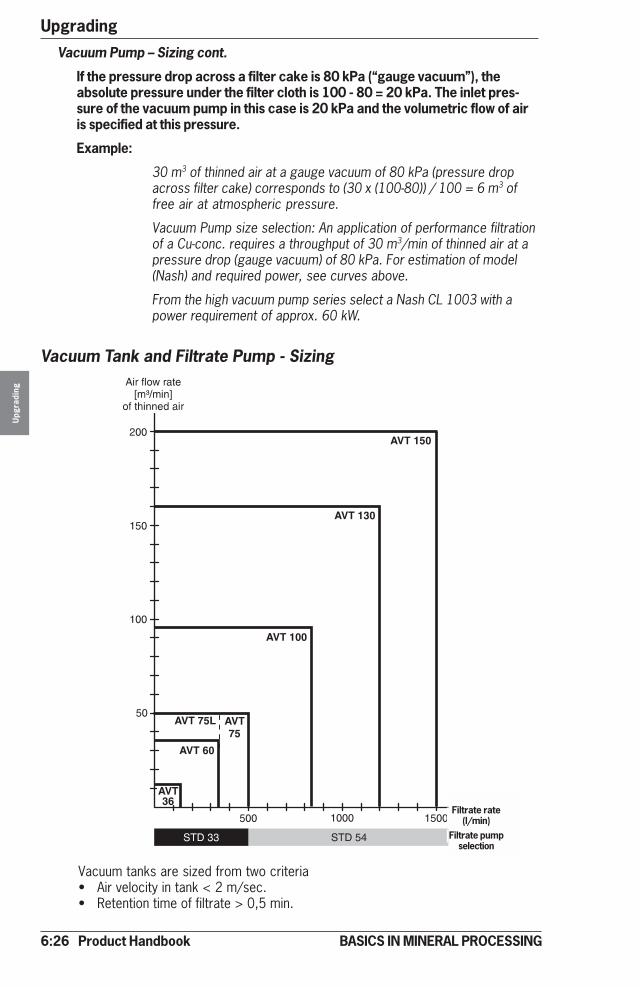
6:26 Product Handbook
UpgradingU
pgra
ding
BASICS IN MINERAL PROCESSING
Vacuum Pump – Sizing cont.
If the pressure drop across a filter cake is 80 kPa (“gauge vacuum”), theabsolute pressure under the filter cloth is 100 - 80 = 20 kPa. The inlet pres-sure of the vacuum pump in this case is 20 kPa and the volumetric flow of airis specified at this pressure.
Example:
30 m3 of thinned air at a gauge vacuum of 80 kPa (pressure dropacross filter cake) corresponds to (30 x (100-80)) / 100 = 6 m3 offree air at atmospheric pressure.
Vacuum Pump size selection: An application of performance filtrationof a Cu-conc. requires a throughput of 30 m3/min of thinned air at apressure drop (gauge vacuum) of 80 kPa. For estimation of model(Nash) and required power, see curves above.
From the high vacuum pump series select a Nash CL 1003 with apower requirement of approx. 60 kW.
Vacuum Tank and Filtrate Pump - Sizing
Vacuum tanks are sized from two criteria• Air velocity in tank < 2 m/sec.• Retention time of filtrate > 0,5 min.
Filtrate rate(l/min)
Filtrate pumpselection
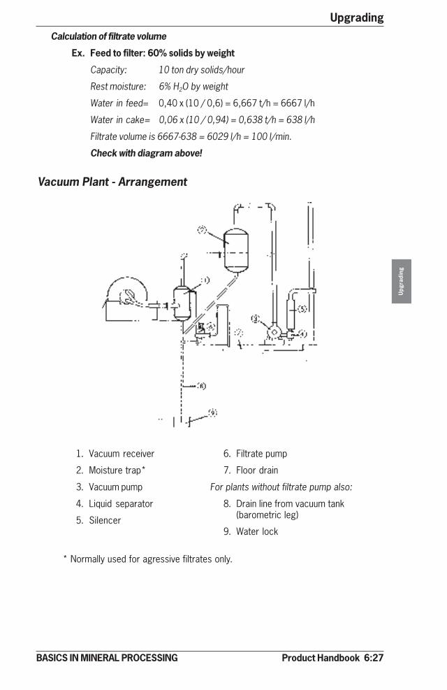
Product Handbook 6:27
Upgrading
Upg
radi
ng
BASICS IN MINERAL PROCESSING
Calculation of filtrate volume
Ex. Feed to filter: 60% solids by weight
Capacity: 10 ton dry solids/hour
Rest moisture: 6% H2O by weight
Water in feed= 0,40 x (10 / 0,6) = 6,667 t/h = 6667 l/h
Water in cake= 0,06 x (10 / 0,94) = 0,638 t/h = 638 l/h
Filtrate volume is 6667-638 = 6029 l/h = 100 l/min.
Check with diagram above!
Vacuum Plant - Arrangement
1. Vacuum receiver
2. Moisture trap*
3. Vacuum pump
4. Liquid separator
5. Silencer
6. Filtrate pump
7. Floor drain
For plants without filtrate pump also:
8. Drain line from vacuum tank(barometric leg)
9. Water lock
* Normally used for agressive filtrates only.
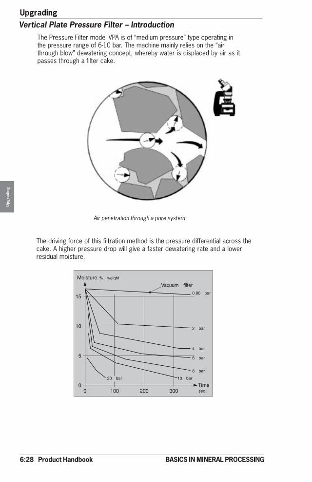
6:28 Product Handbook
UpgradingU
pgra
ding
BASICS IN MINERAL PROCESSING
Vertical Plate Pressure Filter – IntroductionThe Pressure Filter model VPA is of “medium pressure” type operating inthe pressure range of 6-10 bar. The machine mainly relies on the “airthrough blow” dewatering concept, whereby water is displaced by air as itpasses through a filter cake.
Air penetration through a pore system
The driving force of this filtration method is the pressure differential across thecake. A higher pressure drop will give a faster dewatering rate and a lowerresidual moisture.
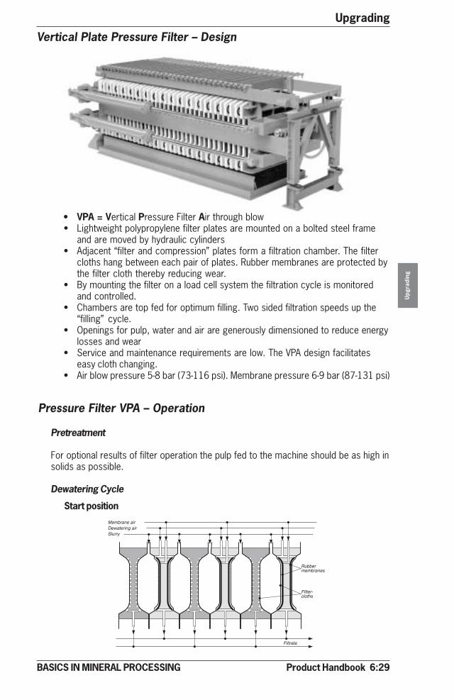
Product Handbook 6:29
Upgrading
Upg
radi
ng
BASICS IN MINERAL PROCESSING
Pretreatment
For optional results of filter operation the pulp fed to the machine should be as high insolids as possible.
Dewatering Cycle
Start position
Vertical Plate Pressure Filter – Design
• VPA = Vertical Pressure Filter Air through blow• Lightweight polypropylene filter plates are mounted on a bolted steel frame
and are moved by hydraulic cylinders• Adjacent “filter and compression” plates form a filtration chamber. The filter
cloths hang between each pair of plates. Rubber membranes are protected bythe filter cloth thereby reducing wear.
• By mounting the filter on a load cell system the filtration cycle is monitoredand controlled.
• Chambers are top fed for optimum filling. Two sided filtration speeds up the“filling” cycle.
• Openings for pulp, water and air are generously dimensioned to reduce energylosses and wear
• Service and maintenance requirements are low. The VPA design facilitateseasy cloth changing.
• Air blow pressure 5-8 bar (73-116 psi). Membrane pressure 6-9 bar (87-131 psi)
Pressure Filter VPA – Operation
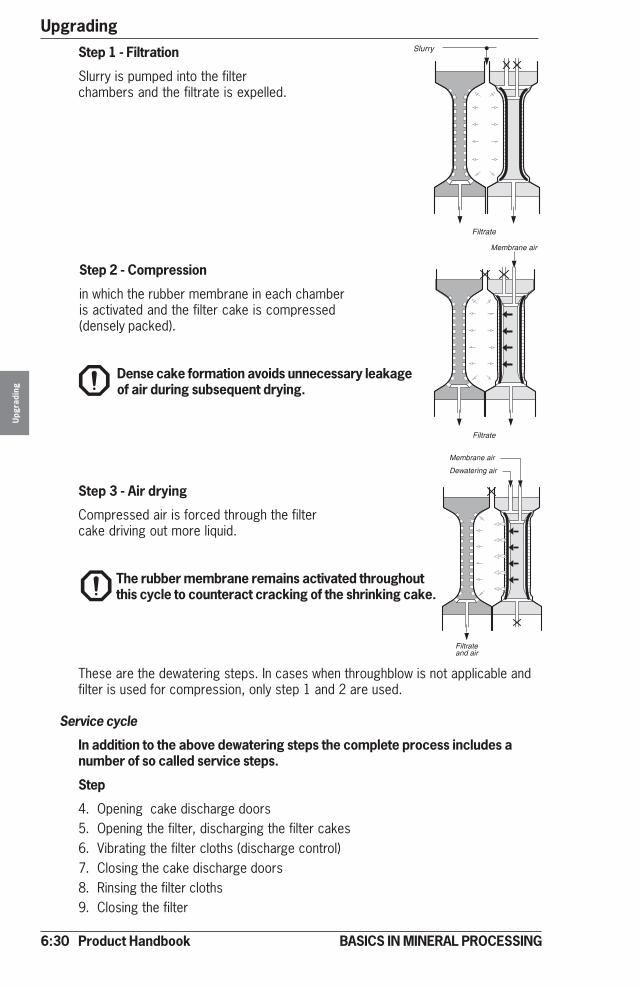
6:30 Product Handbook
UpgradingU
pgra
ding
BASICS IN MINERAL PROCESSING
Step 2 - Compression
in which the rubber membrane in each chamberis activated and the filter cake is compressed(densely packed).
Dense cake formation avoids unnecessary leakageof air during subsequent drying.
These are the dewatering steps. In cases when throughblow is not applicable andfilter is used for compression, only step 1 and 2 are used.
Service cycle
In addition to the above dewatering steps the complete process includes anumber of so called service steps.
Step
4. Opening cake discharge doors5. Opening the filter, discharging the filter cakes6. Vibrating the filter cloths (discharge control)7. Closing the cake discharge doors8. Rinsing the filter cloths9. Closing the filter
Step 3 - Air drying
Compressed air is forced through the filtercake driving out more liquid.
The rubber membrane remains activated throughoutthis cycle to counteract cracking of the shrinking cake.
Step 1 - Filtration
Slurry is pumped into the filterchambers and the filtrate is expelled.
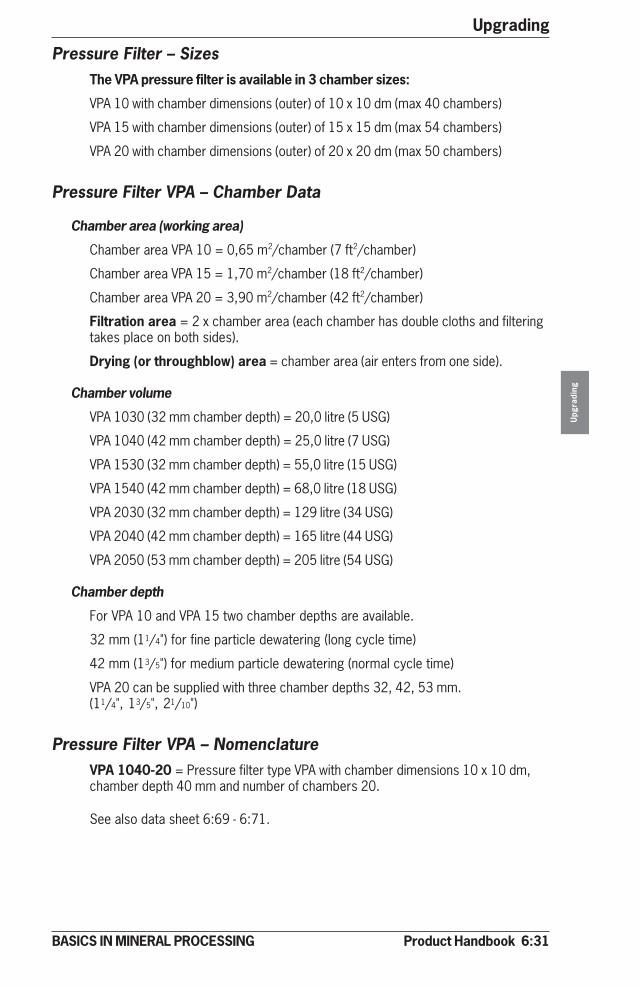
Product Handbook 6:31
Upgrading
Upg
radi
ng
BASICS IN MINERAL PROCESSING
Pressure Filter – SizesThe VPA pressure filter is available in 3 chamber sizes:
VPA 10 with chamber dimensions (outer) of 10 x 10 dm (max 40 chambers)
VPA 15 with chamber dimensions (outer) of 15 x 15 dm (max 54 chambers)
VPA 20 with chamber dimensions (outer) of 20 x 20 dm (max 50 chambers)
Pressure Filter VPA – Chamber Data
Chamber area (working area)
Chamber area VPA 10 = 0,65 m2/chamber (7 ft2/chamber)
Chamber area VPA 15 = 1,70 m2/chamber (18 ft2/chamber)
Chamber area VPA 20 = 3,90 m2/chamber (42 ft2/chamber)
Filtration area = 2 x chamber area (each chamber has double cloths and filteringtakes place on both sides).
Drying (or throughblow) area = chamber area (air enters from one side).
Chamber volume
VPA 1030 (32 mm chamber depth) = 20,0 litre (5 USG)
VPA 1040 (42 mm chamber depth) = 25,0 litre (7 USG)
VPA 1530 (32 mm chamber depth) = 55,0 litre (15 USG)
VPA 1540 (42 mm chamber depth) = 68,0 litre (18 USG)
VPA 2030 (32 mm chamber depth) = 129 litre (34 USG)
VPA 2040 (42 mm chamber depth) = 165 litre (44 USG)
VPA 2050 (53 mm chamber depth) = 205 litre (54 USG)
Chamber depth
For VPA 10 and VPA 15 two chamber depths are available.
32 mm (11/4") for fine particle dewatering (long cycle time)
42 mm (13/5") for medium particle dewatering (normal cycle time)
VPA 20 can be supplied with three chamber depths 32, 42, 53 mm.(11/4", 13/5", 21/10")
Pressure Filter VPA – NomenclatureVPA 1040-20 = Pressure filter type VPA with chamber dimensions 10 x 10 dm,chamber depth 40 mm and number of chambers 20.
See also data sheet 6:69 - 6:71.
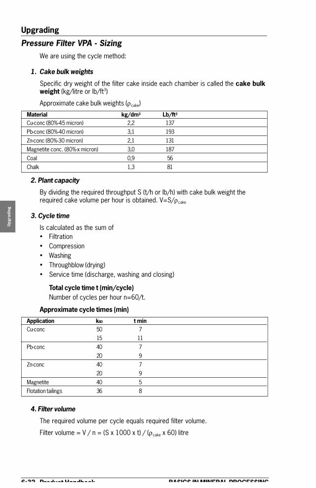
6:32 Product Handbook
Upgrading
Upg
radi
ng
BASICS IN MINERAL PROCESSING
Pressure Filter VPA - SizingWe are using the cycle method:
1. Cake bulk weights
Specific dry weight of the filter cake inside each chamber is called the cake bulkweight (kg/litre or lb/ft3)
Approximate cake bulk weights (ρcake)
Material kg/dm3 Lb/ft3
Cu-conc (80%-45 micron) 2,2 137Pb-conc (80%-40 micron) 3,1 193Zn-conc (80%-30 micron) 2,1 131Magnetite conc. (80%-x micron) 3,0 187Coal 0,9 56Chalk 1,3 81
2. Plant capacity
By dividing the required throughput S (t/h or lb/h) with cake bulk weight therequired cake volume per hour is obtained. V=S/ρcake
3. Cycle time
Is calculated as the sum of� Filtration� Compression� Washing� Throughblow (drying)� Service time (discharge, washing and closing)
Total cycle time t (min/cycle)Number of cycles per hour n=60/t.
Approximate cycle times (min)
Application k80 t minCu-conc 50 7
15 11Pb-conc 40 7
20 9Zn-conc 40 7
20 9Magnetite 40 5Flotation tailings 36 8
4. Filter volume
The required volume per cycle equals required filter volume.
Filter volume = V / n = (S x 1000 x t) / (ρcake x 60) litre
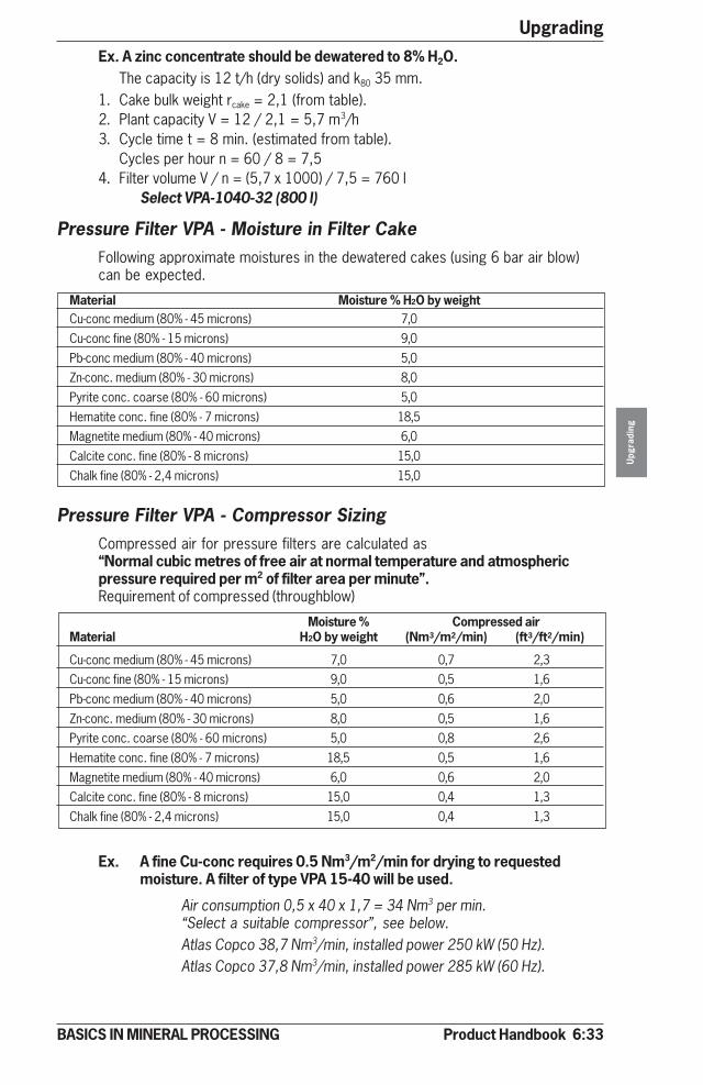
Product Handbook 6:33
Upgrading
Upg
radi
ng
BASICS IN MINERAL PROCESSING
Pressure Filter VPA - Moisture in Filter CakeFollowing approximate moistures in the dewatered cakes (using 6 bar air blow)can be expected.
Material Moisture % H2O by weightCu-conc medium (80% - 45 microns) 7,0Cu-conc fine (80% - 15 microns) 9,0Pb-conc medium (80% - 40 microns) 5,0Zn-conc. medium (80% - 30 microns) 8,0Pyrite conc. coarse (80% - 60 microns) 5,0Hematite conc. fine (80% - 7 microns) 18,5Magnetite medium (80% - 40 microns) 6,0Calcite conc. fine (80% - 8 microns) 15,0Chalk fine (80% - 2,4 microns) 15,0
Pressure Filter VPA - Compressor SizingCompressed air for pressure filters are calculated as“Normal cubic metres of free air at normal temperature and atmosphericpressure required per m2 of filter area per minute”.Requirement of compressed (throughblow)
Moisture % Compressed airMaterial H2O by weight (Nm3/m2/min) (ft3/ft2/min)
Cu-conc medium (80% - 45 microns) 7,0 0,7 2,3Cu-conc fine (80% - 15 microns) 9,0 0,5 1,6Pb-conc medium (80% - 40 microns) 5,0 0,6 2,0Zn-conc. medium (80% - 30 microns) 8,0 0,5 1,6Pyrite conc. coarse (80% - 60 microns) 5,0 0,8 2,6Hematite conc. fine (80% - 7 microns) 18,5 0,5 1,6Magnetite medium (80% - 40 microns) 6,0 0,6 2,0Calcite conc. fine (80% - 8 microns) 15,0 0,4 1,3Chalk fine (80% - 2,4 microns) 15,0 0,4 1,3
Ex. A fine Cu-conc requires 0.5 Nm3/m2/min for drying to requestedmoisture. A filter of type VPA 15-40 will be used.
Air consumption 0,5 x 40 x 1,7 = 34 Nm3 per min.“Select a suitable compressor”, see below.Atlas Copco 38,7 Nm3/min, installed power 250 kW (50 Hz).Atlas Copco 37,8 Nm3/min, installed power 285 kW (60 Hz).
Ex. A zinc concentrate should be dewatered to 8% H2O.The capacity is 12 t/h (dry solids) and k80 35 mm.
1. Cake bulk weight rcake = 2,1 (from table).2. Plant capacity V = 12 / 2,1 = 5,7 m3/h3. Cycle time t = 8 min. (estimated from table).
Cycles per hour n = 60 / 8 = 7,54. Filter volume V / n = (5,7 x 1000) / 7,5 = 760 l
Select VPA-1040-32 (800 l)

6:34 Product Handbook
UpgradingU
pgra
ding
BASICS IN MINERAL PROCESSING
Pressure Filter VPA - Feed Pump Selection (guidance only)For VPA 10, choose 4” slurry pumpFor VPA 15, choose 6” slurry pumpFor VPA 20, choose 8” slurry pump
Pressure Filter VPA - Feed Pump Power (approximate)VPA 10-8 to VPA 10-20 55 kW 74 hpVPA 10-22 to VPA 10-40 75 kW 100 hpVPA 15-10 to VPA 15-20 75 kW 100 hpVPA 15-22 to VPA 15-60 132 kW 177 hpVPA 20-10 to VPA 20-20 160 kW 215 hpVPA 20-22 to VPA 20-60 200 kW 268 hp
Pressure Filter VPA - Product SystemIn a complete dewatering plant the compressed air filter is only one part of whatwe call the VPA system.
The VPA system consists of the following equipment:
Thickener to feed the filter with correct pulp density.
Buffer tank for deaeration and pulp density control prior to pump feeding.
Pressure Filter VPA - Compressor Power(Table below shows Atlas Copco medium pressure water-cooled two-stage screwcompressors (oil free), unload pressure 8 bar (50 Hz) 8.6 bar (60 Hz).
Installed InstalledModel Capacity power Model Capacity power(50 Hz) (Nm3/min) (ft2/min) (kW) (hp) (60 Hz) (Nm3/min) (ft3/min) (kW) (hp)
ZR3-50 11,0 389 75 100 ZR3-60 12,7 449 104 13951 13,6 480 90 120 61 15,8 558 127 17052 16,6 586 110 147 62 19,1 675 148 19853 19,5 689 132 177 63 22,5 795 180 24154 22,4 791 160 215 ZR4-60 24,6 869 184 246ZR4-50 25,1 887 160 215 61 30,8 1 088 230 30851 30,7 1 085 200 268 62 37,8 1 335 285 38252 38,7 1 367 250 335 ZR5-60 44,6 1 576 285 382ZR5-50 46,4 1 639 315 422 61 51,0 1 802 360 48351 50,3 1 777 315 422 62 56,6 2 000 405 54352 61,3 2 166 400 536 63 60,9 2 152 405 54353 68,9 2 434 450 603 ZR6-60 76,2 2 692 - -ZR6-50 79,8 2 819 - - 61 88,2 3 116 - -51 100,5 3 551 - - 62 1 02.0 3 604 - -52 112,5 3 975 - - 63 1 02.8 3 632 - -

Product Handbook 6:35
Upgrading
Upg
radi
ng
BASICS IN MINERAL PROCESSING
Slurry pump for feeding during the filtration cycle. (3)
Valves for pulp, water and air. (4)
Rinse water system for the filter cloths. (5)
Weighing system for optimization of the operational parameters of filtration,compressed air drying, etc.
Compressor for compressed air supply. (6)
Computer based control system for operation and control of the filtrationprocess.
Tube Press – IntroductionAs particles continue to get even finer the VPA system is overruled by the strongparticle binding to water due to extremely powerful capillary forces. The only wayto continue with mechanical dewatering is to move up to higher pressure differ-ences across the filter cake.
This has to be done in a tube, as a conventional pressure filter cannot take up thispressure.
The tube press is a variable volume filter using a flexible membrane to applycompression to the slurry to be dewatered.
1
2
3
4 4
56
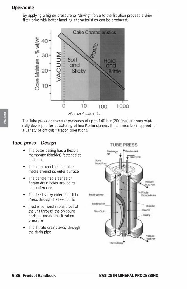
6:36 Product Handbook
UpgradingU
pgra
ding
BASICS IN MINERAL PROCESSING
Tube press – Design• The outer casing has a flexible
membrane (bladder) fastened ateach end
• The inner candle has a filtermedia around its outer surface
• The candle has a series offiltrate drain holes around itscircumference
• The feed slurry enters the TubePress through the feed ports
• Fluid is pumped into and out ofthe unit through the pressureports to create the filtrationpressure
• The filtrate drains away throughthe drain pipe
The Tube press operates at pressures of up to 140 bar (2000psi) and was origi-nally developed for dewatering of fine Kaolin slurries. It has since been applied toa variety of difficult filtration operations.
Filtration Pressure - bar
By applying a higher pressure or “driving” force to the filtration process a drierfilter cake with better handling characteristics can be produced.

Product Handbook 6:37
Upgrading
Upg
radi
ng
BASICS IN MINERAL PROCESSING
Tube press – Operation
The filtration cycle
Step 1 – Starting cycle
The Tube Press will start each cycleempty.
Step 2 – Slurry fill
The Tube Press is then filled with the feedslurry.
• The candle is in the closedposition
• Hydraulic vacuum is applied
• The Bladder is pulled backagainst the casing
The slurry enters the Tube Press throughthe porting in the top of the Candle andfills the annular space between the Filterand the Bladder.
Step 3 – Pressure phase
The filtration is applied by pumping a fluid,usually water, into the Tube Press throughthe pressure ports.
Step 4 – Filtration complete
Eventually the stage is reached where nofurther filtration will take place.
• The pressure water pushes theBladder squeezing the slurryagainst the filter cloth
• The filtrate passes through the flitercloth and runs to drain
• The solids are held by the filtercloth forming a cake
In order to take advantage of the fasterfiltering which occurs in the early stagesand to take any slack in the system, thepressure is initially applied at low pres-sure/high volume. At the appropriate pointhigh pressure water is applied.
• Cake will be formed• Filtrate will no longer flow
The next step in the process will dependon wheter the cycle will include the airpurging or washing of the cake. If air purgeor cake wash is required then the nextstage will be step 4. If not the next stagewill be step 6.
Slurry Fill

6:38 Product Handbook
UpgradingU
pgra
ding
BASICS IN MINERAL PROCESSING
Step 7 – Vacuum
When the final high pressure stage iscompleted it is necessary to enter thedischarge sequense.
• The hydraulic vacuum draws thepressure fluid out of the Tube Press,pulling the Bladder away from thecake
• The Bladder is pulled tight againstthe casing wall
To ensure the Bladder is fully against theCasing wall and away from the Candle thesystem is equipped with a vacuum detec-tor which will give a “proceed” signal whenthe appropriate level of vacuum isreached.
Step 8 – Discharge
When the vacuum level has been achievedthe discharge will proceed.
• Candle is lowered• Air is blown into the Candle expand-
ing the Filter Cloth which in turnfractures the cake which dropsunder gravity
• The pressure fluid is forced out ofthe Tube Press by the incoming airor wash fluid
• The pressure fluid is restricted by aflow restrictor in order that theinternal pressure in the Tube ismaintained. This is necessary toensure that the cake does notfracture
Step 5 – Air purge / Cake wash
If it is necessary to treat the cake by airpurging or washing, the following is carriedout:
Step 6 – Repeat high pressure
Once the Tube Press unit has been filledwith air or wash fluid the hydraulic highpressure is reapplied.
• Air purge:– The air will force further filtrate
from the cake resulting in adrier cake
– The wash fluid may also be used to remove soluble materi-als from the cake
It is possible to carry out multiple airpurges or cake washers
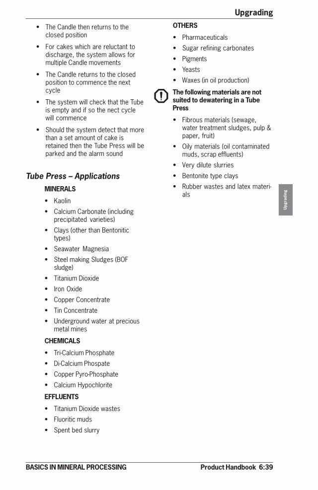
Product Handbook 6:39
Upgrading
Upg
radi
ng
BASICS IN MINERAL PROCESSING
Tube Press – ApplicationsMINERALS
• Kaolin
• Calcium Carbonate (includingprecipitated varieties)
• Clays (other than Bentonitictypes)
• Seawater Magnesia
• Steel making Sludges (BOFsludge)
• Titanium Dioxide
• Iron Oxide
• Copper Concentrate
• Tin Concentrate
• Underground water at preciousmetal mines
CHEMICALS
• Tri-Calcium Phosphate
• Di-Calcium Phospate
• Copper Pyro-Phosphate
• Calcium Hypochlorite
EFFLUENTS
• Titanium Dioxide wastes
• Fluoritic muds
• Spent bed slurry
• The Candle then returns to theclosed position
• For cakes which are reluctant todischarge, the system allows formultiple Candle movements
• The Candle returns to the closedposition to commence the nextcycle
• The system will check that the Tubeis empty and if so the nect cyclewill commence
• Should the system detect that morethan a set amount of cake isretained then the Tube Press will beparked and the alarm sound
OTHERS
• Pharmaceuticals
• Sugar refining carbonates
• Pigments
• Yeasts
• Waxes (in oil production)
The following materials are notsuited to dewatering in a TubePress
• Fibrous materials (sewage,water treatment sludges, pulp &paper, fruit)
• Oily materials (oil contaminatedmuds, scrap effluents)
• Very dilute slurries
• Bentonite type clays
• Rubber wastes and latex materi-als
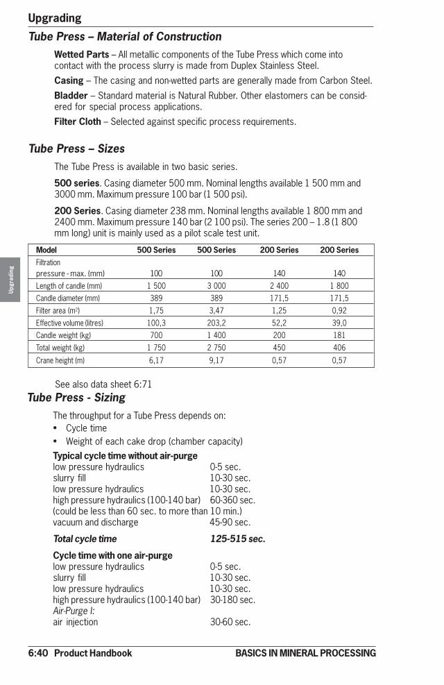
6:40 Product Handbook
UpgradingU
pgra
ding
BASICS IN MINERAL PROCESSING
Tube Press – SizesThe Tube Press is available in two basic series.
500 series. Casing diameter 500 mm. Nominal lengths available 1 500 mm and3000 mm. Maximum pressure 100 bar (1 500 psi).
200 Series. Casing diameter 238 mm. Nominal lengths available 1 800 mm and2400 mm. Maximum pressure 140 bar (2 100 psi). The series 200 – 1.8 (1 800mm long) unit is mainly used as a pilot scale test unit.
Model 500 Series 500 Series 200 Series 200 SeriesFiltrationpressure - max. (mm) 100 100 140 140Length of candle (mm) 1 500 3 000 2 400 1 800Candle diameter (mm) 389 389 171,5 171,5Filter area (m2) 1,75 3,47 1,25 0,92Effective volume (litres) 100,3 203,2 52,2 39,0Candle weight (kg) 700 1 400 200 181Total weight (kg) 1 750 2 750 450 406
Crane height (m) 6,17 9,17 0,57 0,57
Tube Press - SizingThe throughput for a Tube Press depends on:• Cycle time• Weight of each cake drop (chamber capacity)Typical cycle time without air-purgelow pressure hydraulics 0-5 sec.slurry fill 10-30 sec.low pressure hydraulics 10-30 sec.high pressure hydraulics (100-140 bar) 60-360 sec.(could be less than 60 sec. to more than 10 min.)vacuum and discharge 45-90 sec.
Total cycle time 125-515 sec.
Cycle time with one air-purgelow pressure hydraulics 0-5 sec.slurry fill 10-30 sec.low pressure hydraulics 10-30 sec.high pressure hydraulics (100-140 bar) 30-180 sec.Air-Purge I:air injection 30-60 sec.
Tube Press – Material of ConstructionWetted Parts – All metallic components of the Tube Press which come intocontact with the process slurry is made from Duplex Stainless Steel.
Casing – The casing and non-wetted parts are generally made from Carbon Steel.
Bladder – Standard material is Natural Rubber. Other elastomers can be consid-ered for special process applications.
Filter Cloth – Selected against specific process requirements.
See also data sheet 6:71
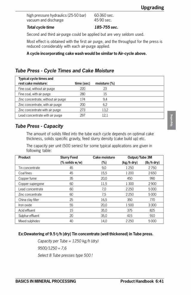
Product Handbook 6:41
Upgrading
Upg
radi
ng
BASICS IN MINERAL PROCESSING
high pressure hydraulics (25-50 bar) 60-360 sec.vacuum and discharge 45-90 sec.
Total cycle time 185-755 sec.
Second and third air-purge could be applied but are very seldom used.
Most effect is obtained with the first air purge, and the throughput for the press isreduced considerably with each air-purge applied.
A cycle incorporating cake wash would be similar to Air-cycle above.
Tube Press - Cycle Times and Cake MoistureTypical cycle times andrest cake moisture: time (sec) moisture (%)Fine coal, without air purge 220 23Fine coal, with air purge 280 15Zinc concentrate, without air purge 174 9,4Zinc concentrate, with air purge 200 6,2Zinc concentrate with air purge 273 13,2Lead concentrate with air purge 297 12,1
Tube Press - CapacityThe amount of solids filled into the tube each cycle depends on optimal cakethickness, solids specific gravity, feed slurry density (cake build up) etc.
The capacity per unit (500 series) for some typical applications are given infollowing table:
Product Slurry Feed Cake moisture Output/Tube 3M(% solids w/w) (%) (kg/h dry) (lb/h dry)
Tin concentrate 45 9,0 1 250 2 750Coal fines 45 15,5 1 200 2 650Copper fume 35 20,0 450 990Copper supergene 60 11,5 1 300 2 900Lead concentrate 60 7,0 2 250 5 000Zinc concentrate 60 7,5 2 250 5 000China clay filler 25 16,5 350 770Iron oxide 55 20,0 1 500 3 300Acid effluent 15 35,0 375 825Sulphur effluent 20 35,0 415 910Mixed sulphides 40 14,0 2 250 5 000
Ex:Dewatering of 9.5 t/h (dry) Tin concentrate (well thickened) in Tube press.
Capacity per Tube = 1250 kg/h (dry)
9500/1250 = 7,6
Select 8 Tube presses type 500 !
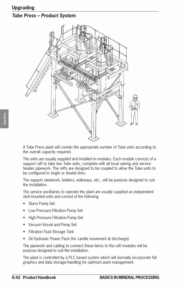
6:42 Product Handbook
UpgradingU
pgra
ding
BASICS IN MINERAL PROCESSING
Tube Press – Product System
A Tube Press plant will contain the appropriate number of Tube units according tothe overall capacity required.
The units are usually supplied and installed in modules. Each module consists of asupport raft to take two Tube units, complete with all local valving and serviceheader pipework. The rafts are designed to be coupled to allow the Tube units tobe configured in single or double lines.
The support steelwork, ladders, walkways, etc., will be purpose designed to suitthe installation.
The service ancilliaries to operate the plant are usually supplied as independentskid mounted units and consist of the following
• Slurry Pump Set
• Low Pressure Filtration Pump Set
• High Pressure Filtration Pump Set
• Vacuum Vessel and Pump Set
• Filtration Fluid Storage Tank
• Oil Hydraulic Power Pack (for candle movement at discharge)
The pipework and cabling to connect these items to the raft modules will bepurpose designed to suit the installation.
The plant is controlled by a PLC based system which will normally incorporate fullgraphics and data storage/handling for optimum plant management.
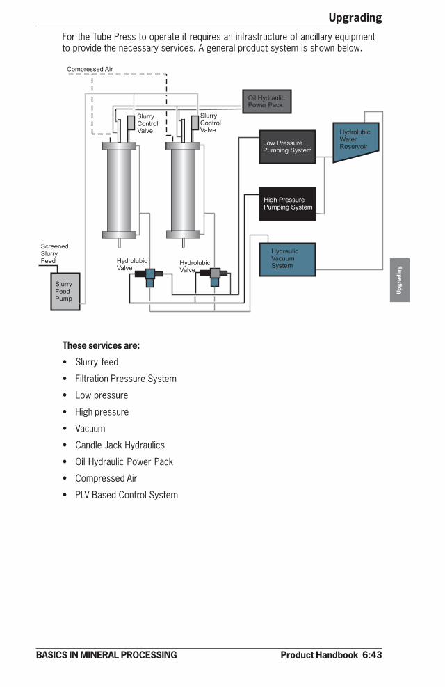
Product Handbook 6:43
Upgrading
Upg
radi
ng
BASICS IN MINERAL PROCESSING
For the Tube Press to operate it requires an infrastructure of ancillary equipmentto provide the necessary services. A general product system is shown below.
These services are:
• Slurry feed
• Filtration Pressure System
• Low pressure
• High pressure
• Vacuum
• Candle Jack Hydraulics
• Oil Hydraulic Power Pack
• Compressed Air
• PLV Based Control System

6:44 Product Handbook
UpgradingU
pgra
ding
BASICS IN MINERAL PROCESSING
Thermal processing – IntroductionDewatering by using Tube Presses represents the highest energy level of mechani-cal upgrading of minerals. If further upgrading is required we have to use thermalprocessing.Thermal processing is normally classified according to operating temperature.
Thermal low ( 100-200° C)
Used for drying - evaporating of liquids from solids - dryingType of equipment• Direct Heat Rotary Dryers• Indirect Heat Rotary Dryers• Steam Tube Dryers• Indirect Heat Screw Dryers (Holo-FliteR)• Fluid Bed Dryers
Thermal medium (850 -950°C)
Used for calcining, clay swelling, limestone burning and foundry sand burn outType of equipment• Direct Heat Rotary kilns• Indirect Heat Rotary kilns• Vertical Kilns• Fluid bed Kilns
Thermal high (1300-1400°C)
Used for pelletizing of iron ore concentrates and petroleum coke calciningType of equipment• Direct heat rotary kiln
Thermal processing-basics
Thermal processing is expensive. This means that lowest input in calories/ton isthe key issue. With raising operating temperatures this issue is getting more andmore critical.Dryers are normally not insulated but the kilns are refractory lined to protect themechanical parts from the high temperatures needed for processing. Also thesystems for heat recovery are getting more and more advanced with higherenergy input.Thermal processing equipment is always supplied as an integrated system consist-ing of:
• Mechanical Dryer or Kiln, see above• Feed and product handling equipment• Combustion system (burner, fans, fuel system, etc.)• Offgas handling equipment• Dust collection system (wet or dry)• Cooling system (optional)
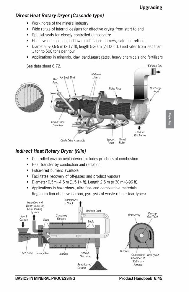
Product Handbook 6:45
Upgrading
Upg
radi
ng
BASICS IN MINERAL PROCESSING
Direct Heat Rotary Dryer (Cascade type)• Work horse of the mineral industry• Wide range of internal designs for effective drying from start to end• Special seals for closely controlled atmosphere• Effective combustion and low maintenance burners, safe and reliable• Diameter <0,6-5 m (2-17 ft), length 5-30 m (7-100 ft). Feed rates from less than
1 ton to 500 tons per hour• Applications in minerals, clay, sand,aggregates, heavy chemicals and fertilizers
Indirect Heat Rotary Dryer (Kiln)• Controlled environment interior excludes products of combustion• Heat transfer by conduction and radiation• Pulse-fired burners available• Facilitates recovery of off-gases and product vapours• Diameter 0,5m - 4,5 m (1.5-14 ft). Length 2.5 m to 30 m (8-96 ft).• Applications in hazardous-, ultra fine- and combustible materials.
Regenera tion of active carbon, pyrolysis of waste rubber (car types)
Exhaust Gas
DischargeHood
Riding Ring
MaterialLiftersShellAir SealWet
Feed
Burner
CombustionChamber
Chain Drive Assembly SupportRoller
ThrustRoller
ProductDischarge
SpentCarbon
Impurities andWater Vapor toGas Cleaning
System
Seals
Exhaust Gasto Stack
StationaryFurnace
Seals
Recoup Duct
Feed Srew Rotary Kiln Burners RecoupGas Tube
ReactivatedCarbon
Refractory RecoupGas Tube
BurnersCombustionChamber ofStationaryFurnace
Rotary Kiln
See data sheet 6:72.

6:46 Product Handbook
UpgradingU
pgra
ding
BASICS IN MINERAL PROCESSING
Steam Tube Dryer• Indirect heating avoids product contamination• Essentially automatic ( dryer adjusts to fluctuations in evaporation load).• Low in maintenance, safe and reliable• Steam pressure can range from 1,5 to 20 bar. Utilizes waste steam• Capacities of 3 to 50 ton/hour, heating surfaces up to 2,250 m² (24,000 ft).• Diameter 1-4 m (3-14 ft), length 3-30 m (10-100 ft).• Applications for heat sensitive materials, see also indirect drying above
See data sheet 6:73.
Vertical Kiln• Mainly for Lime-Calcining applications
• No moving parts concept
• Vertical mild steel shaft, refractory lined
• Top charging for feed, bottom discharge
• 3 zones shaft for preheat, calcining and cooling
• Maximised heat recovery by interchange of zone gases
• Up to 200 t/day capacity limestone feed
Non-CondensiblesCollecting Ring
RidingRing
Tube SupportsExhaust Gas
SealsSteam
ManifoldSteamInlet
Condensate
ProductDischarge
Thrust Roller
Gear DriveAssemblyDrive MotorSupport
Roller
SteamTubes
Seal
Wet Feed
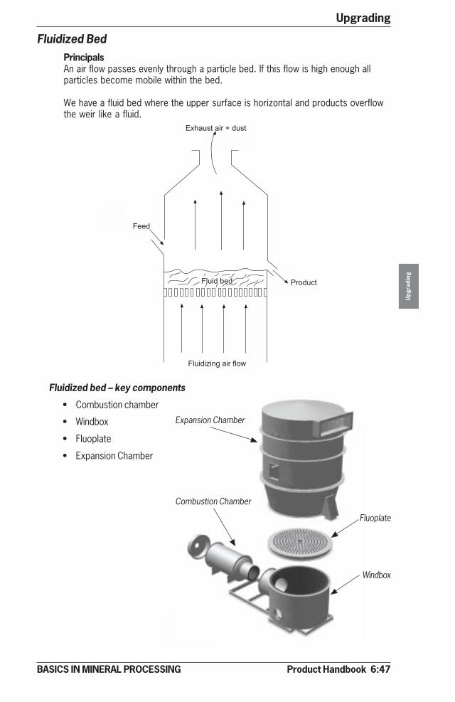
Product Handbook 6:47
Upgrading
Upg
radi
ng
BASICS IN MINERAL PROCESSING
Fluidized bed – key components
• Combustion chamber
• Windbox
• Fluoplate
• Expansion Chamber
Fluidized BedPrincipalsAn air flow passes evenly through a particle bed. If this flow is high enough allparticles become mobile within the bed.
We have a fluid bed where the upper surface is horizontal and products overflowthe weir like a fluid.
Product
����
������� ������
������
�� � � ���� ������
�� �����
Expansion Chamber
Combustion Chamber
Fluoplate
Windbox
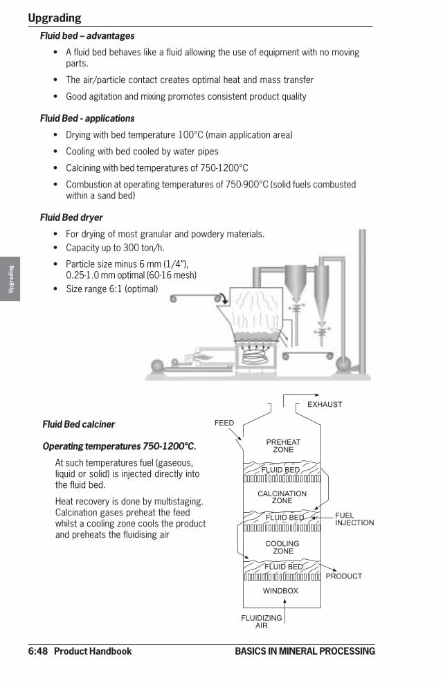
6:48 Product Handbook
UpgradingU
pgra
ding
BASICS IN MINERAL PROCESSING
Fluid Bed calciner
Operating temperatures 750-1200°C.
At such temperatures fuel (gaseous,liquid or solid) is injected directly intothe fluid bed.
Heat recovery is done by multistaging.Calcination gases preheat the feedwhilst a cooling zone cools the productand preheats the fluidising air
Fluid bed – advantages
• A fluid bed behaves like a fluid allowing the use of equipment with no movingparts.
• The air/particle contact creates optimal heat and mass transfer
• Good agitation and mixing promotes consistent product quality
Fluid Bed - applications
• Drying with bed temperature 100°C (main application area)
• Cooling with bed cooled by water pipes
• Calcining with bed temperatures of 750-1200°C
• Combustion at operating temperatures of 750-900°C (solid fuels combustedwithin a sand bed)
Fluid Bed dryer
• For drying of most granular and powdery materials.• Capacity up to 300 ton/h.
• Particle size minus 6 mm (1/4”),0.25-1.0 mm optimal (60-16 mesh)
• Size range 6:1 (optimal)
�������
� �����!"#�
���$
�%�&$�'�$
(�%(&#��&"#!"#�
�%�&$�'�$
(""%&#)!"#�
*&#$'"�
�%�&$�'�$
�%�&$&!&#)�&
���%&#+�(�&"#
� "$�(�
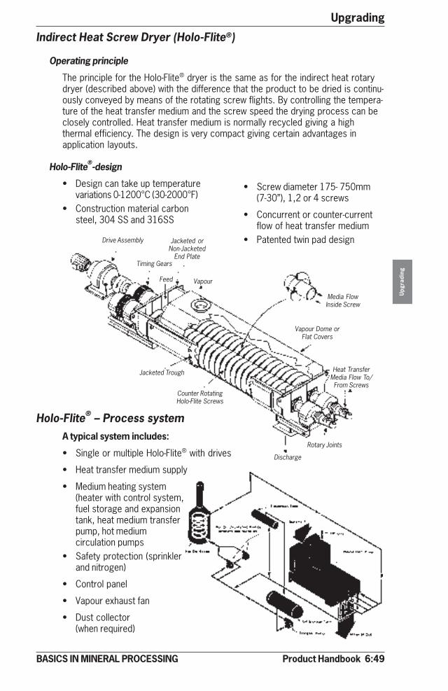
Product Handbook 6:49
Upgrading
Upg
radi
ng
BASICS IN MINERAL PROCESSING
Holo-Flite® – Process systemA typical system includes:
• Single or multiple Holo-Flite® with drives
• Heat transfer medium supply
• Medium heating system(heater with control system,fuel storage and expansiontank, heat medium transferpump, hot mediumcirculation pumps
• Safety protection (sprinklerand nitrogen)
• Control panel
• Vapour exhaust fan
• Dust collector(when required)
Indirect Heat Screw Dryer (Holo-Flite®)
Operating principle
The principle for the Holo-Flite® dryer is the same as for the indirect heat rotarydryer (described above) with the difference that the product to be dried is continu-ously conveyed by means of the rotating screw flights. By controlling the tempera-ture of the heat transfer medium and the screw speed the drying process can beclosely controlled. Heat transfer medium is normally recycled giving a highthermal efficiency. The design is very compact giving certain advantages inapplication layouts.
Holo-Flite®-design
• Design can take up temperaturevariations 0-1200°C (30-2000°F)
• Construction material carbonsteel, 304 SS and 316SS
• Screw diameter 175- 750mm(7-30”), 1,2 or 4 screws
• Concurrent or counter-currentflow of heat transfer medium
• Patented twin pad designDrive Assembly
Timing Gears
Feed
Jacketed orNon-Jacketed
End Plate
Vapour
Media FlowInside Screw
Vapour Dome orFlat Covers
Heat TransferMedia Flow To/From Screws
Rotary Joints
Discharge
Counter RotatingHolo-Flite Screws
Jacketed Trough
6:50 Product Handbook
UpgradingU
pgra
ding
BASICS IN MINERAL PROCESSING
Holo-Flite® - Heat transfer medium
Steam (up to 10 bar) 100 - 200°C 200 - 400°FHot Oil 150 - 350°C 300 - 660°F
Holo-Flite® - applications
The importance with a Holo-Flite® application is that the material shall be con-veyed in a screw conveyor and that the material must not adhere to the transport-ing flights. Maximum recommended particle size is 12 mm (1/2”).
With these restriction a lot of applications open up for this concept
• Coal fines• Mineral fines• Carbon black• Iron powder• Other valuable granular and powdery material
Holo-Flite® - sizing
As for the rest of thermal processing equipment sizing, this is a complicatedcomputer exercise normally based on lab- or pilot test work.
Some typical drying application figures:
Limestone fines 12 t/h 15°C in 138°C outEquipment used: one 4-screw machine, flight dia 600 mm(24”). Length 7.2m (24ft)
Potassium chloride 9 t/h 0°C in 110°C outEquipment used: one 2-screw machine, flight dia 400 mm(16”). Length 6 m (20 ft)
See also data sheet 6:75.
Something about coolingIn most thermal processing the temperatures of discharged products are high. Inorder to lower that temperature, or to recover some heat, or both, coolers areused.
Most of the coolers are inversely working dryers, however, with a higher capacityper installed unit.
Coolers of rotating drum type
Normally there are three basic designs:
• Air Swept Coolers built similar as a counter flow direct heat rotary dryer,where hot gasses are replaced with ambient air
• Water cooled shell coolers where the drum shell is cooled with water or issubmerged in a pool of water.
• Water tube coolers having the same design as a steam tube dryer, where thesteam is replaced with cool water
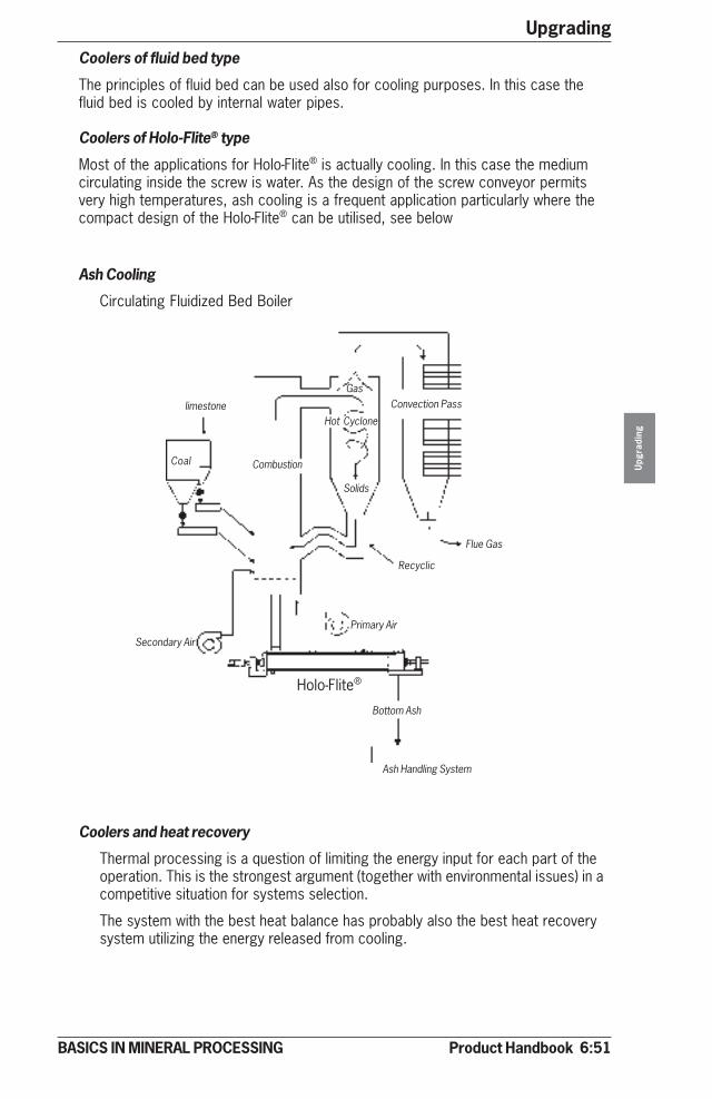
Product Handbook 6:51
Upgrading
Upg
radi
ng
BASICS IN MINERAL PROCESSING
Coolers of fluid bed type
The principles of fluid bed can be used also for cooling purposes. In this case thefluid bed is cooled by internal water pipes.
Coolers of Holo-Flite® type
Most of the applications for Holo-Flite® is actually cooling. In this case the mediumcirculating inside the screw is water. As the design of the screw conveyor permitsvery high temperatures, ash cooling is a frequent application particularly where thecompact design of the Holo-Flite® can be utilised, see below
Ash Cooling
Circulating Fluidized Bed Boiler
Coolers and heat recovery
Thermal processing is a question of limiting the energy input for each part of theoperation. This is the strongest argument (together with environmental issues) in acompetitive situation for systems selection.
The system with the best heat balance has probably also the best heat recoverysystem utilizing the energy released from cooling.
Flue Gas
Recyclic
Convection PassGas
Hot Cyclone
Solids
Primary Air
Bottom Ash
Ash Handling System
Holo-Flite®
Secondary Air
CombustionCoal
limestone
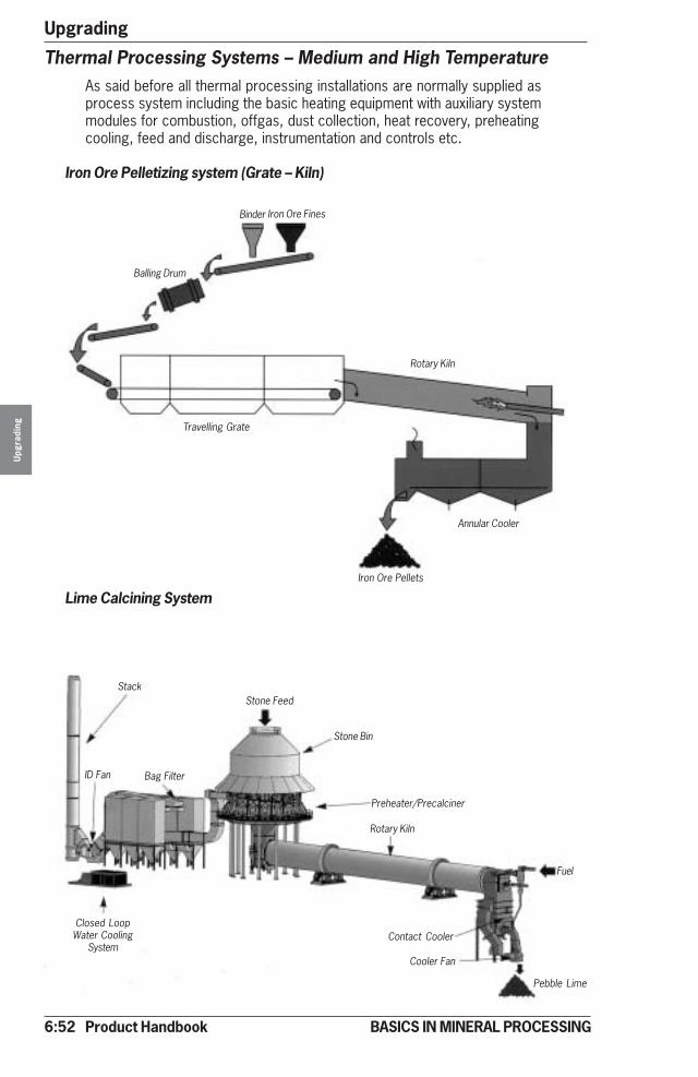
6:52 Product Handbook
UpgradingU
pgra
ding
BASICS IN MINERAL PROCESSING
Thermal Processing Systems – Medium and High TemperatureAs said before all thermal processing installations are normally supplied asprocess system including the basic heating equipment with auxiliary systemmodules for combustion, offgas, dust collection, heat recovery, preheatingcooling, feed and discharge, instrumentation and controls etc.
Iron Ore Pelletizing system (Grate – Kiln)
Lime Calcining System
Balling Drum
Binder Iron Ore Fines
Rotary Kiln
Iron Ore Pellets
Annular Cooler
Travelling Grate
Stack
Bag Filter
Stone Feed
Stone Bin
Preheater/Precalciner
ID Fan
Closed LoopWater Cooling
System
Rotary Kiln
Contact Cooler
Fuel
Cooler Fan
Pebble Lime
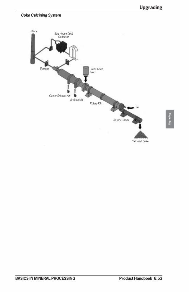
Product Handbook 6:53
Upgrading
Upg
radi
ng
BASICS IN MINERAL PROCESSING
Coke Calcining System
StackBag House Dust
Collector
Green CokeFeed
Damper
Cooler Exhaust AirAmbient Air
Rotary Kiln
Rotary Cooler
Calcined Coke
Fuel

6:54 Product Handbook
UpgradingU
pgra
ding
BASICS IN MINERAL PROCESSING
Technical Data Sheet
Diameter Area(m) (ft) (m2) (ft2)10 33 78 839
12 39 113 1 216
14 46 154 1 658
16 52 201 2 164
18 59 254 2 734
20 66 314 3 380
22 72 380 4 090
24 79 452 4 865
26 85 531 5 716
28 92 616 6 631
30 98 706 7 599
32 105 804 8 654
34 111 908 9 773
36 118 1 018 10 958
38 125 1 134 12 206
40 131 1 257 13 530
42 138 1 385 14 913
44 144 1 521 16 367
Clarifier / Thickener – Bridge
D
H

Product Handbook 6:55
Upgrading
Upg
radi
ng
BASICS IN MINERAL PROCESSING
Technical Data Sheet
Clarifier / Thickener – Centre Pier
Diameter Area(m) (ft) (m2) (ft2)
40 131 1 257 13 530
42 138 1 385 14 913
44 144 1 521 16 367
46 151 1 662 17 889
48 157 1 810 19 479
50 164 1 963 21 130
52 170 2 124 22 860
54 177 2 290 24 653
56 184 2 463 26 512
58 190 2 642 28 440
60 197 2 827 30 430
D
H

6:56 Product Handbook
Upgrading
Upg
radi
ng
BASICS IN MINERAL PROCESSING
Technical Data Sheet
Inclined Plate Settler – LT
Model H L W A Total Sludge Flocculator Weight(max) volume volume volume empty
mm mm mm mm m³ m³ m³ m3 kg(ft) (ft) (ft) (ft) (ft³) (ft³) (ft³) (lbs)
LT 15 3 485 2 640 1 345 1 800 4,6 1,1 0,8 1 800
(11,4) (8,7) (4,4) (5,9) (162) (39) (28) (3 968)
LT 30 4 300 3 430 1 830 1 800 9,2 2,3 0,8 3 500
(14,1) (11,3) (6,0) (5,9) (325) (81) (28) (7 716)
LT 50 4 650 3 865 2 230 1 800 16,2 4,2 2,0 4 800
(15,3) (12,7) (7,3) (5,9) (572) (148) (71) (10 582)
LT 100 5 400 4 510 2 870 1 800 28,7 9,4 3,0 7 800
(17,7) (14,8) (9,4) (5,9) (1 014) (332) (106) (17 196)
LT 150 5 950 5 540 3 100 1 800 41,5 14,5 4,0 10 500
(19,5) (18,2) (10,2) (5,9) (1 466) (512) (141) (23 149)
LT 200 6 500 5 740 3 690 1 800 54,6 18,8 5,0 13 200
(21,3) (18,8) (12,1) (5,9) (1 928) (664) (177) (29 101)
LT 350 8 100 6 910 4 500 2 000 105,8 47,8 7,0 24 300
(26,6) (22,7) (14,8) (6,6) (3 736) (1 688) (247) (53 572)
LT 500 8 630 7 810 5 780 2 000 160,8 72,8 8,0 39 500
(28,3) (25,6) (19,0) (6,6) (5 679) (2 571) (283) (87 082)

Product Handbook 6:57
Upgrading
BASICS IN MINERAL PROCESSING
Technical Data Sheet
Inclined Plate Settler – LTS
Model H L W A Total Sludge Flocculator Weight(max) max volume volume volume emptymm mm mm m³ m³ m³ m3
(ft) (ft) (ft) (ft³) (ft³) (ft³) (ft3)LTS 15 3 750 2 640 1 345 1 800 5,2 1,7 0,8 2 000
(12,3) (8,7) (4,4) (5,91) (184) (60) (28) (4 409)
LTS 30 4 620 3 430 1 830 1 800 11,1 4,2 0,8 3 700
(15,2) (11,3) (6,0) (5,91) (392) (148) (28) (8 157)
LTS 50 4 700 3 865 2 230 1 800 18,6 6,6 2,0 5 100
(15,4) (12,7) (7,3) (5,91) (657) (233) (71) (11 244)
LTS 100 5 130 4 510 2 870 1 800 32,5 13,2 3,0 8 600
(16,8) (14,8) (9,4) (5,91) (1 148) (466) (106) (18 960)
LTS 150 5 300 5 540 3 100 1 800 45,8 18,8 4,0 11 300
(17,4) (18,2) (10,2) (5,91) (1 617) (664) (141) (24 912)
LTS 200 6 100 5 740 3 690 1 800 61,8 26,0 5,0 15 800
(20,01) (18,8) (12,1) (5,91) (2 182) (918) (177) (34 833)
LTS 350 6 200 6 910 4 500 2 000 114,0 56,0 7,0 23 000
(20,3) (22,7) (14,8) (6,56) (4 026) (1 978) (247) (50 706)
LTS 500 6 400 7 810 5 780 2 000 153,0 65,0 8,0 36 000
(21,0) (25,6) (19,0) (6,56) (5 403) (2 295) (283) (79 366)
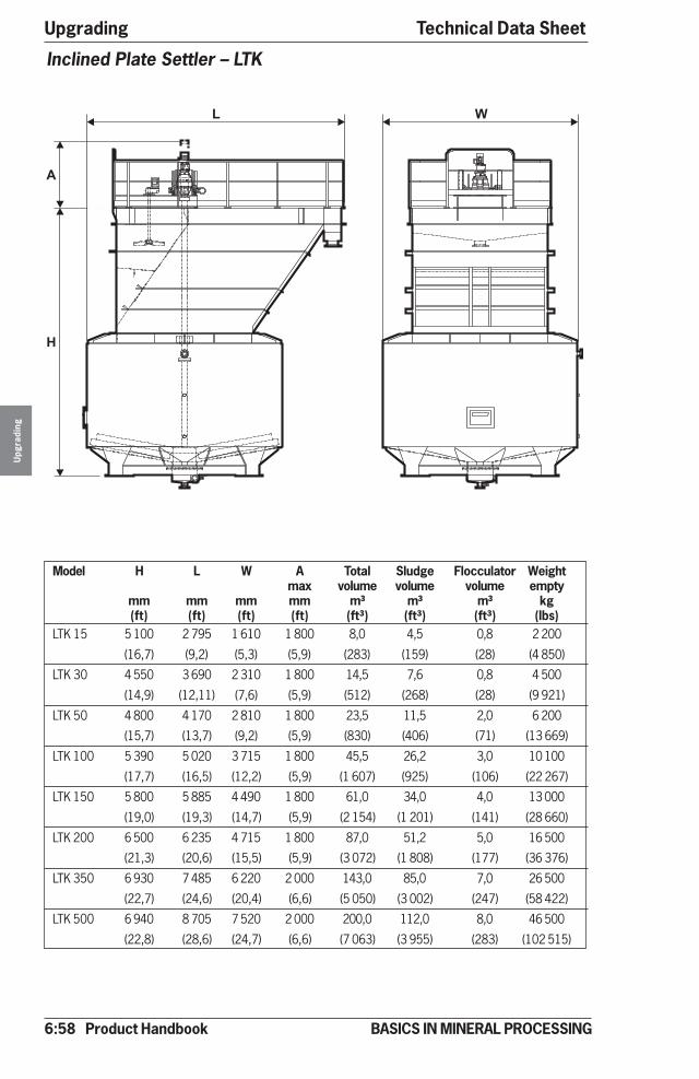
6:58 Product Handbook
UpgradingU
pgra
ding
BASICS IN MINERAL PROCESSING
Technical Data Sheet
Inclined Plate Settler – LTK
Model H L W A Total Sludge Flocculator Weightmax volume volume volume empty
mm mm mm mm m³ m³ m³ kg(ft) (ft) (ft) (ft) (ft³) (ft³) (ft³) (lbs)
LTK 15 5 100 2 795 1 610 1 800 8,0 4,5 0,8 2 200
(16,7) (9,2) (5,3) (5,9) (283) (159) (28) (4 850)
LTK 30 4 550 3 690 2 310 1 800 14,5 7,6 0,8 4 500
(14,9) (12,11) (7,6) (5,9) (512) (268) (28) (9 921)
LTK 50 4 800 4 170 2 810 1 800 23,5 11,5 2,0 6 200
(15,7) (13,7) (9,2) (5,9) (830) (406) (71) (13 669)
LTK 100 5 390 5 020 3 715 1 800 45,5 26,2 3,0 10 100
(17,7) (16,5) (12,2) (5,9) (1 607) (925) (106) (22 267)
LTK 150 5 800 5 885 4 490 1 800 61,0 34,0 4,0 13 000
(19,0) (19,3) (14,7) (5,9) (2 154) (1 201) (141) (28 660)
LTK 200 6 500 6 235 4 715 1 800 87,0 51,2 5,0 16 500
(21,3) (20,6) (15,5) (5,9) (3 072) (1 808) (177) (36 376)
LTK 350 6 930 7 485 6 220 2 000 143,0 85,0 7,0 26 500
(22,7) (24,6) (20,4) (6,6) (5 050) (3 002) (247) (58 422)
LTK 500 6 940 8 705 7 520 2 000 200,0 112,0 8,0 46 500
(22,8) (28,6) (24,7) (6,6) (7 063) (3 955) (283) (102 515)
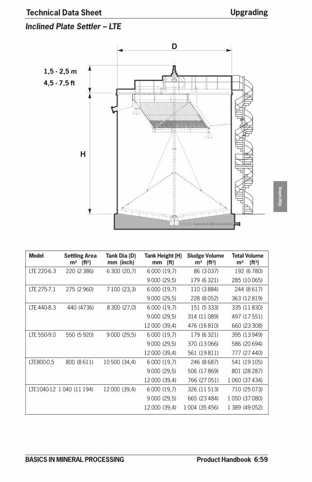
Product Handbook 6:59
Upgrading
Upg
radi
ng
BASICS IN MINERAL PROCESSING
Technical Data Sheet
Inclined Plate Settler – LTE
Model Settling Area Tank Dia (D) Tank Height (H) Sludge Volume Total Volumem2 (ft2) mm (inch) mm (ft) m3 (ft3) m3 (ft3)
LTE 220-6.3 220 (2 386) 6 300 (20,7) 6 000 (19,7) 86 (3 037) 192 (6 780)
9 000 (29,5) 179 (6 321) 285 (10 065)
LTE 275-7.1 275 (2 960) 7 100 (23,3) 6 000 (19,7) 110 (3 884) 244 (8 617)
9 000 (29,5) 228 (8 052) 363 (12 819)
LTE 440-8.3 440 (4736) 8 300 (27,0) 6 000 (19,7) 151 (5 333) 335 (11 830)
9 000 (29,5) 314 (11 089) 497 (17 551)
12 000 (39,4) 476 (16 810) 660 (23 308)
LTE 550-9.0 550 (5 920) 9 000 (29,5) 6 000 (19,7) 179 (6 321) 395 (13 949)
9 000 (29,5) 370 (13 066) 586 (20 694)
12 000 (39,4) 561 (19 811) 777 (27 440)
LTE800-0.5 800 (8 611) 10 500 (34,4) 6 000 (19,7) 246 (8 687) 541 (19 105)
9 000 (29,5) 506 (17 869) 801 (28 287)
12 000 (39,4) 766 (27 051) 1 060 (37 434)
LTE1040-12 1 040 (11 194) 12 000 (39,4) 6 000 (19,7) 326 (11 513) 710 (25 073)
9 000 (29,5) 665 (23 484) 1 050 (37 080)
12 000 (39,4) 1 004 (35 456) 1 389 (49 052)
1,5 - 2,5 m
4,5 - 7,5 ft
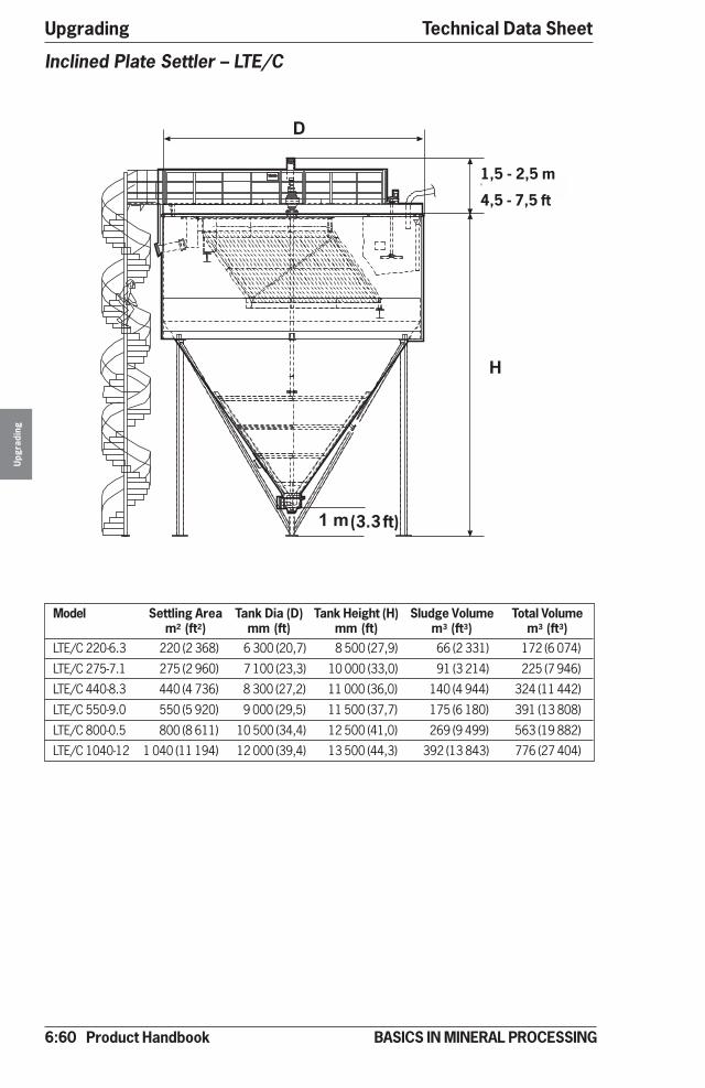
6:60 Product Handbook
UpgradingU
pgra
ding
BASICS IN MINERAL PROCESSING
Technical Data Sheet
�
����������
���
Inclined Plate Settler – LTE/C
Model Settling Area Tank Dia (D) Tank Height (H) Sludge Volume Total Volumem2 (ft2) mm (ft) mm (ft) m3 (ft3) m3 (ft3)
LTE/C 220-6.3 220 (2 368) 6 300 (20,7) 8 500 (27,9) 66 (2 331) 172 (6 074)
LTE/C 275-7.1 275 (2 960) 7 100 (23,3) 10 000 (33,0) 91 (3 214) 225 (7 946)
LTE/C 440-8.3 440 (4 736) 8 300 (27,2) 11 000 (36,0) 140 (4 944) 324 (11 442)
LTE/C 550-9.0 550 (5 920) 9 000 (29,5) 11 500 (37,7) 175 (6 180) 391 (13 808)
LTE/C 800-0.5 800 (8 611) 10 500 (34,4) 12 500 (41,0) 269 (9 499) 563 (19 882)
LTE/C 1040-12 1 040 (11 194) 12 000 (39,4) 13 500 (44,3) 392 (13 843) 776 (27 404)
(3.3 ft)
1,5 - 2,5 m
4,5 - 7,5 ft

Product Handbook 6:61
Upgrading
Upg
radi
ng
BASICS IN MINERAL PROCESSING
Technical Data Sheet
Spiral Dewaterer
�
�
�
Model H mm (inch) L mm (inch) W mm (inch) Power Weight Tankvolume
kW/hp ton(empty) m³ (ft³)SD 60-8* 2 815 (111) 7 340 (289) 2 300 (91) 1.5/2 9.0 8 (283)
SD 60-10 3 160 (124) 8 370 (330) 2 300 (91) 1.5/2 9.3 12 (424)
SD 60-20 4 000 (157) 10 600 (417) 3 200 (126) 3/4 12.5 30 (1 059)
SD 60-25 5 350 (211) 11 100 (437) 4 500 (177) 3/4 13.8 44 (1 554)
SD 60-30 6 400 (252) 14 000 (551) 5 000 (197) 4/5 23.0 70 (2 472)
SD 60-38** 5 350 (211) 11 100 (437) 4 500 (177) 3/4 14.4 44 (1 5 54)
SD 60-100** 6 400 (252) 14 000 (551) 5 000 (197) 4/5 24.4 70 (2 473)
*60-8, 60 = spiral dia in cm (24inch) -8 = settling area 8m² (86ft²)
10m² (108ft²), 20m² (216ft²), 25m² (270ft²), 30m² (323ft²), 38m²(409ft²), 100m² (1 080ft²)
** With lamella plates
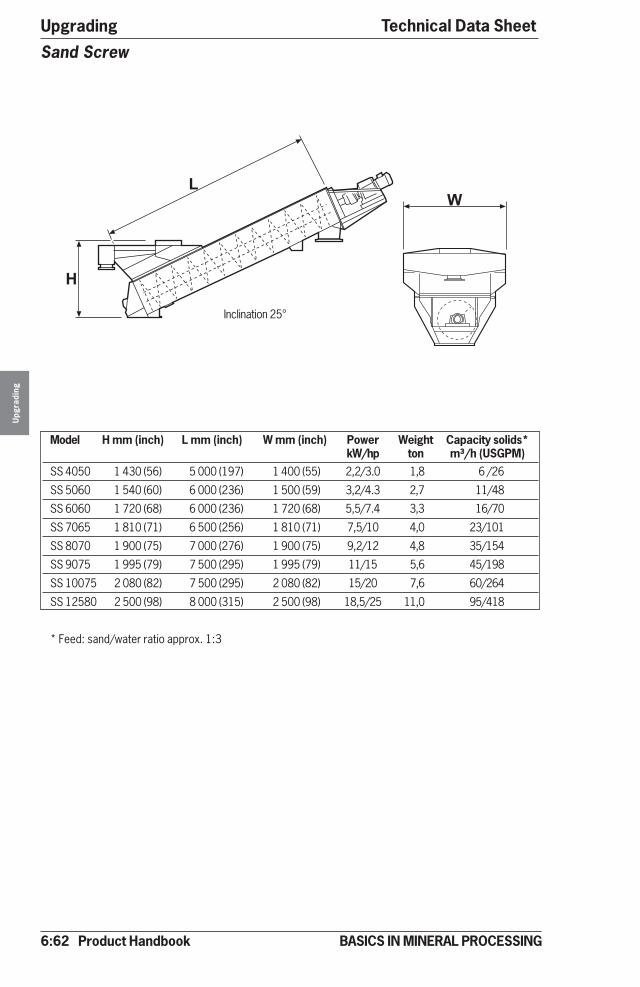
6:62 Product Handbook
UpgradingU
pgra
ding
BASICS IN MINERAL PROCESSING
Technical Data Sheet
Model H mm (inch) L mm (inch) W mm (inch) Power Weight Capacity solids*kW/hp ton m³/h (USGPM)
SS 4050 1 430 (56) 5 000 (197) 1 400 (55) 2,2/3.0 1,8 6 /26
SS 5060 1 540 (60) 6 000 (236) 1 500 (59) 3,2/4.3 2,7 11/48
SS 6060 1 720 (68) 6 000 (236) 1 720 (68) 5,5/7.4 3,3 16/70
SS 7065 1 810 (71) 6 500 (256) 1 810 (71) 7,5/10 4,0 23/101
SS 8070 1 900 (75) 7 000 (276) 1 900 (75) 9,2/12 4,8 35/154
SS 9075 1 995 (79) 7 500 (295) 1 995 (79) 11/15 5,6 45/198
SS 10075 2 080 (82) 7 500 (295) 2 080 (82) 15/20 7,6 60/264
SS 12580 2 500 (98) 8 000 (315) 2 500 (98) 18,5/25 11,0 95/418
* Feed: sand/water ratio approx. 1:3
Sand Screw
��
Inclination 25°
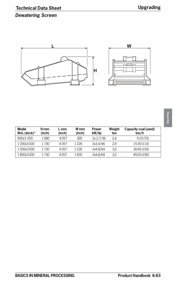
Product Handbook 6:63
Upgrading
Upg
radi
ng
BASICS IN MINERAL PROCESSING
Technical Data SheetDewatering Screen
Model H mm L mm W mm Power Weight Capacity coal (sand)WxL (deck)* (inch) (inch) (inch) kW/hp ton ton/h900x3 000 1 680 4 057 920 2x 2,7/36 2,4 5-15 (70)
1 200x3 000 1 730 4 057 1 226 2x3,4/46 2,9 15-30 (110)
1 500x3 000 1 730 4 057 1 530 2x4,8/64 3,0 30-45 (150)
1 800x3 000 1 730 4 057 1 835 2x4,8/64 3,2 45-55 (190)
��
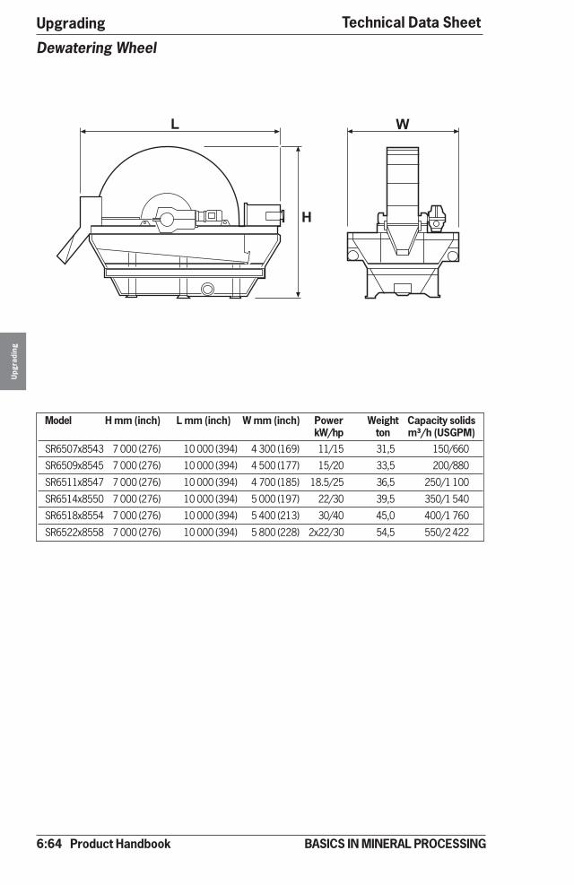
6:64 Product Handbook
UpgradingU
pgra
ding
BASICS IN MINERAL PROCESSING
Technical Data Sheet
Model H mm (inch) L mm (inch) W mm (inch) Power Weight Capacity solidskW/hp ton m³/h (USGPM)
SR6507x8543 7 000 (276) 10 000 (394) 4 300 (169) 11/15 31,5 150/660
SR6509x8545 7 000 (276) 10 000 (394) 4 500 (177) 15/20 33,5 200/880
SR6511x8547 7 000 (276) 10 000 (394) 4 700 (185) 18.5/25 36,5 250/1 100
SR6514x8550 7 000 (276) 10 000 (394) 5 000 (197) 22/30 39,5 350/1 540
SR6518x8554 7 000 (276) 10 000 (394) 5 400 (213) 30/40 45,0 400/1 760
SR6522x8558 7 000 (276) 10 000 (394) 5 800 (228) 2x22/30 54,5 550/2 422
Dewatering Wheel
� �
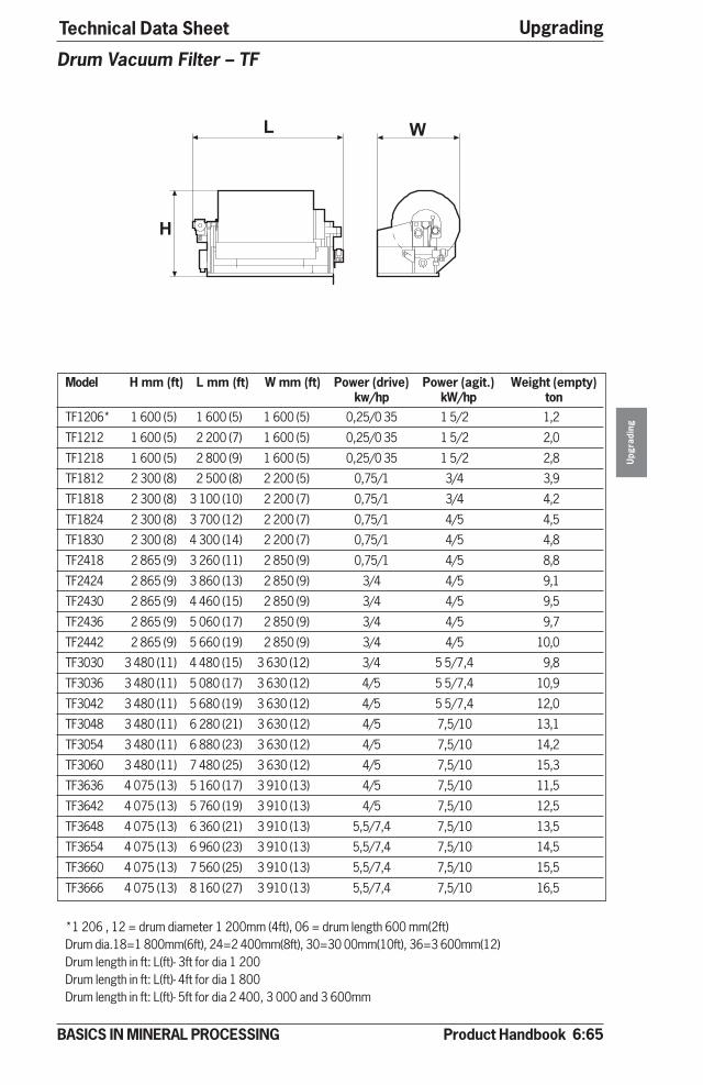
Product Handbook 6:65
Upgrading
Upg
radi
ng
BASICS IN MINERAL PROCESSING
Technical Data Sheet
Model H mm (ft) L mm (ft) W mm (ft) Power (drive) Power (agit.) Weight (empty)kw/hp kW/hp ton
TF1206* 1 600 (5) 1 600 (5) 1 600 (5) 0,25/0 35 1 5/2 1,2
TF1212 1 600 (5) 2 200 (7) 1 600 (5) 0,25/0 35 1 5/2 2,0
TF1218 1 600 (5) 2 800 (9) 1 600 (5) 0,25/0 35 1 5/2 2,8
TF1812 2 300 (8) 2 500 (8) 2 200 (5) 0,75/1 3/4 3,9
TF1818 2 300 (8) 3 100 (10) 2 200 (7) 0,75/1 3/4 4,2
TF1824 2 300 (8) 3 700 (12) 2 200 (7) 0,75/1 4/5 4,5
TF1830 2 300 (8) 4 300 (14) 2 200 (7) 0,75/1 4/5 4,8
TF2418 2 865 (9) 3 260 (11) 2 850 (9) 0,75/1 4/5 8,8
TF2424 2 865 (9) 3 860 (13) 2 850 (9) 3/4 4/5 9,1
TF2430 2 865 (9) 4 460 (15) 2 850 (9) 3/4 4/5 9,5
TF2436 2 865 (9) 5 060 (17) 2 850 (9) 3/4 4/5 9,7
TF2442 2 865 (9) 5 660 (19) 2 850 (9) 3/4 4/5 10,0
TF3030 3 480 (11) 4 480 (15) 3 630 (12) 3/4 5 5/7,4 9,8
TF3036 3 480 (11) 5 080 (17) 3 630 (12) 4/5 5 5/7,4 10,9
TF3042 3 480 (11) 5 680 (19) 3 630 (12) 4/5 5 5/7,4 12,0
TF3048 3 480 (11) 6 280 (21) 3 630 (12) 4/5 7,5/10 13,1
TF3054 3 480 (11) 6 880 (23) 3 630 (12) 4/5 7,5/10 14,2
TF3060 3 480 (11) 7 480 (25) 3 630 (12) 4/5 7,5/10 15,3
TF3636 4 075 (13) 5 160 (17) 3 910 (13) 4/5 7,5/10 11,5
TF3642 4 075 (13) 5 760 (19) 3 910 (13) 4/5 7,5/10 12,5
TF3648 4 075 (13) 6 360 (21) 3 910 (13) 5,5/7,4 7,5/10 13,5
TF3654 4 075 (13) 6 960 (23) 3 910 (13) 5,5/7,4 7,5/10 14,5
TF3660 4 075 (13) 7 560 (25) 3 910 (13) 5,5/7,4 7,5/10 15,5
TF3666 4 075 (13) 8 160 (27) 3 910 (13) 5,5/7,4 7,5/10 16,5
*1 206 , 12 = drum diameter 1 200mm (4ft), 06 = drum length 600 mm(2ft)Drum dia.18=1 800mm(6ft), 24=2 400mm(8ft), 30=30 00mm(10ft), 36=3 600mm(12)Drum length in ft: L(ft)- 3ft for dia 1 200Drum length in ft: L(ft)- 4ft for dia 1 800Drum length in ft: L(ft)- 5ft for dia 2 400, 3 000 and 3 600mm
Drum Vacuum Filter – TF
� �
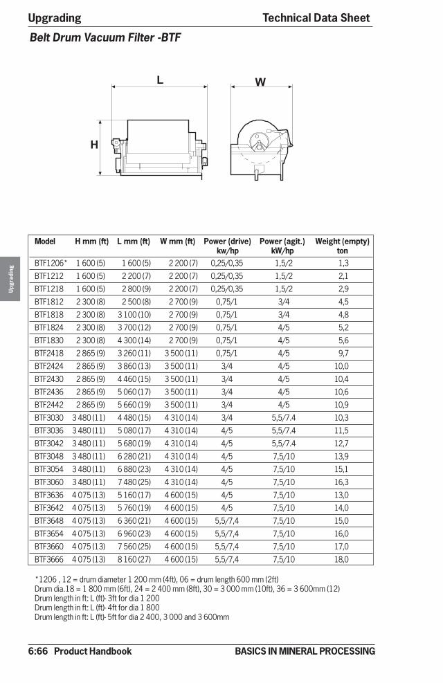
6:66 Product Handbook
UpgradingU
pgra
ding
BASICS IN MINERAL PROCESSING
Technical Data Sheet
�
Model H mm (ft) L mm (ft) W mm (ft) Power (drive) Power (agit.) Weight (empty)kw/hp kW/hp ton
BTF1206* 1 600 (5) 1 600 (5) 2 200 (7) 0,25/0,35 1,5/2 1,3
BTF1212 1 600 (5) 2 200 (7) 2 200 (7) 0,25/0,35 1,5/2 2,1
BTF1218 1 600 (5) 2 800 (9) 2 200 (7) 0,25/0,35 1,5/2 2,9
BTF1812 2 300 (8) 2 500 (8) 2 700 (9) 0,75/1 3/4 4,5
BTF1818 2 300 (8) 3 100 (10) 2 700 (9) 0,75/1 3/4 4,8
BTF1824 2 300 (8) 3 700 (12) 2 700 (9) 0,75/1 4/5 5,2
BTF1830 2 300 (8) 4 300 (14) 2 700 (9) 0,75/1 4/5 5,6
BTF2418 2 865 (9) 3 260 (11) 3 500 (11) 0,75/1 4/5 9,7
BTF2424 2 865 (9) 3 860 (13) 3 500 (11) 3/4 4/5 10,0
BTF2430 2 865 (9) 4 460 (15) 3 500 (11) 3/4 4/5 10,4
BTF2436 2 865 (9) 5 060 (17) 3 500 (11) 3/4 4/5 10,6
BTF2442 2 865 (9) 5 660 (19) 3 500 (11) 3/4 4/5 10,9
BTF3030 3 480 (11) 4 480 (15) 4 310 (14) 3/4 5,5/7.4 10,3
BTF3036 3 480 (11) 5 080 (17) 4 310 (14) 4/5 5,5/7.4 11,5
BTF3042 3 480 (11) 5 680 (19) 4 310 (14) 4/5 5,5/7.4 12,7
BTF3048 3 480 (11) 6 280 (21) 4 310 (14) 4/5 7,5/10 13,9
BTF3054 3 480 (11) 6 880 (23) 4 310 (14) 4/5 7,5/10 15,1
BTF3060 3 480 (11) 7 480 (25) 4 310 (14) 4/5 7,5/10 16,3
BTF3636 4 075 (13) 5 160 (17) 4 600 (15) 4/5 7,5/10 13,0
BTF3642 4 075 (13) 5 760 (19) 4 600 (15) 4/5 7,5/10 14,0
BTF3648 4 075 (13) 6 360 (21) 4 600 (15) 5,5/7,4 7,5/10 15,0
BTF3654 4 075 (13) 6 960 (23) 4 600 (15) 5,5/7,4 7,5/10 16,0
BTF3660 4 075 (13) 7 560 (25) 4 600 (15) 5,5/7,4 7,5/10 17,0
BTF3666 4 075 (13) 8 160 (27) 4 600 (15) 5,5/7,4 7,5/10 18,0
*1206 , 12 = drum diameter 1 200 mm (4ft), 06 = drum length 600 mm (2ft)Drum dia.18 = 1 800 mm (6ft), 24 = 2 400 mm (8ft), 30 = 3 000 mm (10ft), 36 = 3 600mm (12)Drum length in ft: L (ft)- 3ft for dia 1 200Drum length in ft: L (ft)- 4ft for dia 1 800Drum length in ft: L (ft)- 5ft for dia 2 400, 3 000 and 3 600mm
Belt Drum Vacuum Filter -BTF
�
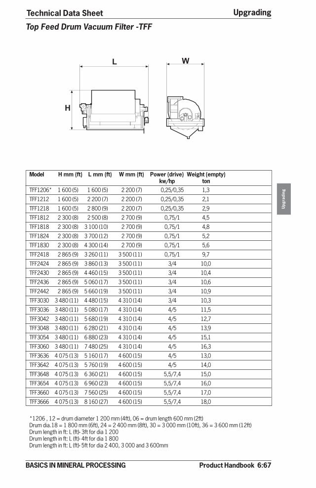
Product Handbook 6:67
Upgrading
Upg
radi
ng
BASICS IN MINERAL PROCESSING
Technical Data Sheet
�
Model H mm (ft) L mm (ft) W mm (ft) Power (drive) Weight (empty)kw/hp ton
TFF1206* 1 600 (5) 1 600 (5) 2 200 (7) 0,25/0,35 1,3
TFF1212 1 600 (5) 2 200 (7) 2 200 (7) 0,25/0,35 2,1
TFF1218 1 600 (5) 2 800 (9) 2 200 (7) 0,25/0,35 2,9
TFF1812 2 300 (8) 2 500 (8) 2 700 (9) 0,75/1 4,5
TFF1818 2 300 (8) 3 100 (10) 2 700 (9) 0,75/1 4,8
TFF1824 2 300 (8) 3 700 (12) 2 700 (9) 0,75/1 5,2
TFF1830 2 300 (8) 4 300 (14) 2 700 (9) 0,75/1 5,6
TFF2418 2 865 (9) 3 260 (11) 3 500 (11) 0,75/1 9,7
TFF2424 2 865 (9) 3 860 (13) 3 500 (11) 3/4 10,0
TFF2430 2 865 (9) 4 460 (15) 3 500 (11) 3/4 10,4
TFF2436 2 865 (9) 5 060 (17) 3 500 (11) 3/4 10,6
TFF2442 2 865 (9) 5 660 (19) 3 500 (11) 3/4 10,9
TFF3030 3 480 (11) 4 480 (15) 4 310 (14) 3/4 10,3
TFF3036 3 480 (11) 5 080 (17) 4 310 (14) 4/5 11,5
TFF3042 3 480 (11) 5 680 (19) 4 310 (14) 4/5 12,7
TFF3048 3 480 (11) 6 280 (21) 4 310 (14) 4/5 13,9
TFF3054 3 480 (11) 6 880 (23) 4 310 (14) 4/5 15,1
TFF3060 3 480 (11) 7 480 (25) 4 310 (14) 4/5 16,3
TFF3636 4 075 (13) 5 160 (17) 4 600 (15) 4/5 13,0
TFF3642 4 075 (13) 5 760 (19) 4 600 (15) 4/5 14,0
TFF3648 4 075 (13) 6 360 (21) 4 600 (15) 5,5/7,4 15,0
TFF3654 4 075 (13) 6 960 (23) 4 600 (15) 5,5/7,4 16,0
TFF3660 4 075 (13) 7 560 (25) 4 600 (15) 5,5/7,4 17,0
TFF3666 4 075 (13) 8 160 (27) 4 600 (15) 5,5/7,4 18,0
*1206 , 12 = drum diameter 1 200 mm (4ft), 06 = drum length 600 mm (2ft)Drum dia.18 = 1 800 mm (6ft), 24 = 2 400 mm (8ft), 30 = 3 000 mm (10ft), 36 = 3 600 mm (12ft)Drum length in ft: L (ft)- 3ft for dia 1 200Drum length in ft: L (ft)- 4ft for dia 1 800Drum length in ft: L (ft)- 5ft for dia 2 400, 3 000 and 3 600mm
Top Feed Drum Vacuum Filter -TFF
�

6:68 Product Handbook
UpgradingU
pgra
ding
BASICS IN MINERAL PROCESSING
Technical Data Sheet
L W
H
Model H mm (inch) L mm (inch) W mm (inch) Weight Power**(empty) (hydraulic motor)
ton high kW/hp low kW/hpVPA 10..-12* 2 310 (91) 5 500 (217) 2 750 (108) 7,2 22/30 11/15
VPA 10..-16 2 310 (91) 6 100 (240) 2 750 (108) 8,1 22/30 11/15
VPA 10..-20 2 310 (91) 6 700 (264) 2 750 (108) 9,0 22/30 11/15
VPA 10..-24 2 310 (91) 7 300 (287) 2 750 (108) 10,0 22/30 11/15
VPA 10..-28 2 310 (91) 7 900 (311) 2 750 (108) 11,8 22/30 11/15
VPA 10..-32 2 310 (91) 8 500 (335) 2 750 (108) 12,9 22/30 11/15
VPA 10..-36 2 310 (91) 9 100 (358) 2 750 (108) 14,0 22/30 11/15
VPA 10..-40 2 310 (91) 9 700 (382) 2 750 (108) 15,1 22/30 11/15
* 1012, 10 = filter chamber size10x 10 dm (40x40 inch),12 = number of chambers** High = high pressure stage, Low = low pressure stage
Pressure Filter –VPA 10

Product Handbook 6:69
Upgrading
Upg
radi
ng
BASICS IN MINERAL PROCESSING
Technical Data Sheet
L W
H
Model H mm (inch) L mm (inch) W mm (inch) Weight Power**(empty) (hydraulic motor)
ton high kW/hp low kW/hpVPA 15..-16* 3 160 (125) 7 600 (299) 3 800 (150) 24,7 45/60 22/30
VPA 15..-20 3 160 (125) 7 900 (311) 3 800 (150) 26,1 45/60 22/30
VPA 15..-24 3 160 (125) 8 500 (335) 3 800 (150) 27,5 45/60 22/30
VPA 15..-28 3 160 (125) 9 100 (358) 3 800 (150) 28,9 45/60 22/30
VPA 15..-32 3 160 (125) 9 700 (382) 3 800 (150) 31,2 45/60 22/30
VPA 15..-36 3 160 (125) 10 300 (406) 3 800 (150) 32,0 45/60 22/30
VPA 15..-40 3 160 (125) 10 900 (429) 3 800 (150) 33,2 45/60 22/30
VPA 15..-46 3 160 (125) 11 800 (465) 3 800 (150) 34,3 45/60 22/30
VPA 15..-50 3 160 (125) 12 400 (488) 3 800 (150) 37,5 45/60 22/30
VPA 15..-54 3 160 (125) 13 100 (516) 3 800 (150) 39,2 45/60 22/30
* 1516, 15 = filter chamber size15x 15 dm (60x60 inch),16 = number of chambers** High = high pressure stage, Low = low pressure stage
Pressure Filter – VPA 15
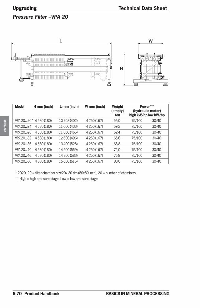
6:70 Product Handbook
UpgradingU
pgra
ding
BASICS IN MINERAL PROCESSING
Technical Data Sheet
L W
H
Model H mm (inch) L mm (inch) W mm (inch) Weight Power**(empty) (hydraulic motor)
ton high kW/hp low kW/hpVPA 20..-20* 4 580 (180) 10 203 (402) 4 250 (167) 56,0 75/100 30/40
VPA 20..-24 4 580 (180) 11 000 (433) 4 250 (167) 59,2 75/100 30/40
VPA 20..-28 4 580 (180) 11 800 (465) 4 250 (167) 62,4 75/100 30/40
VPA 20..-32 4 580 (180) 12 600 (496) 4 250 (167) 65,6 75/100 30/40
VPA 20..-36 4 580 (180) 13 400 (528) 4 250 (167) 68,8 75/100 30/40
VPA 20..-40 4 580 (180) 14 200 (559) 4 250 (167) 72,0 75/100 30/40
VPA 20..-46 4 580 (180) 14 800 (583) 4 250 (167) 76,8 75/100 30/40
VPA 20..-50 4 580 (180) 15 600 (615) 4 250 (167) 80,0 75/100 30/40
* 2020, 20 = filter chamber size20x 20 dm (80x80 inch), 20 = number of chambers
** High = high pressure stage, Low = low pressure stage
Pressure Filter –VPA 20
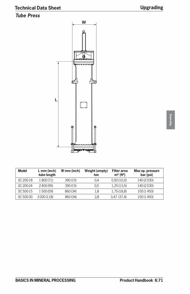
Product Handbook 6:71
Upgrading
Upg
radi
ng
BASICS IN MINERAL PROCESSING
Technical Data Sheet
�
�
Model L mm (inch) W mm (inch) Weight (empty) Filter area Max op. pressuretube length ton m² (ft²) bar (psi)
SC 200-18 1 800 (71) 390 (15) 0,4 0,92 (10,0) 140 (2 030)
SC 200-24 2 400 (95) 390 (15) 0,5 1,25 (13,5) 140 (2 030)
SC 500-15 1 500 (59) 860 (34) 1,8 1,75 (18,8) 100 (1 450)
SC 500-30 3 000 (118) 860 (34) 2,8 3,47 (37,4) 100 (1 450)
Tube Press
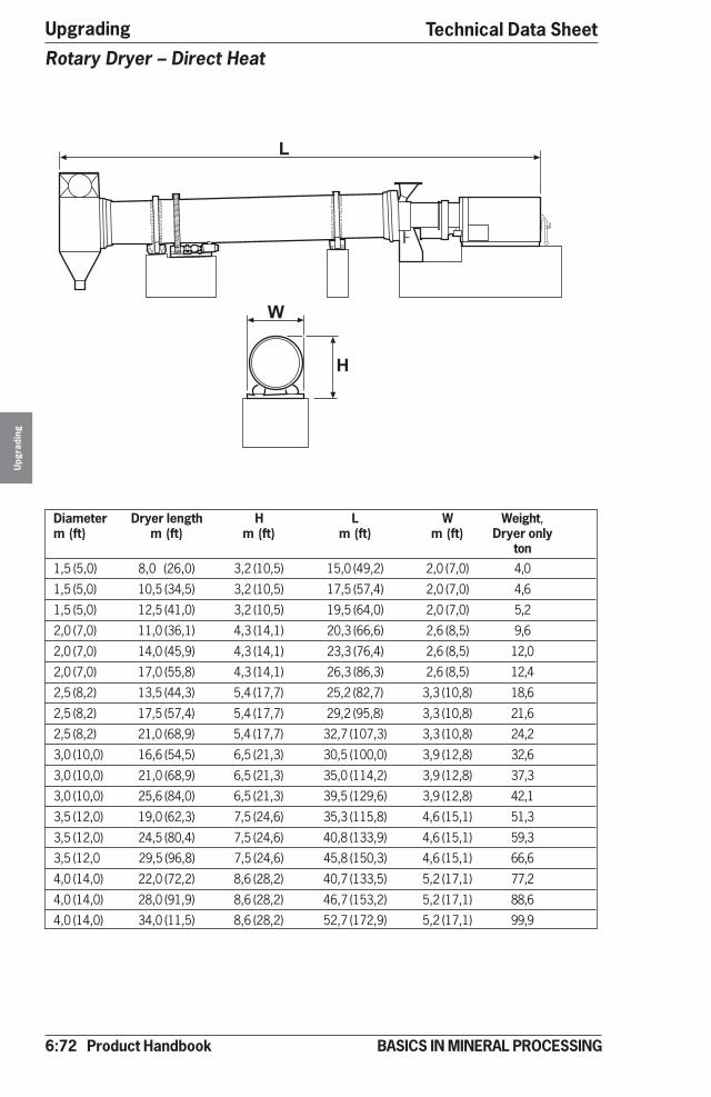
6:72 Product Handbook
UpgradingU
pgra
ding
BASICS IN MINERAL PROCESSING
�
�
Rotary Dryer – Direct Heat
Diameter Dryer length H L W Weight,m (ft) m (ft) m (ft) m (ft) m (ft) Dryer only
ton1,5 (5,0) 8,0 (26,0) 3,2 (10,5) 15,0 (49,2) 2,0 (7,0) 4,0
1,5 (5,0) 10,5 (34,5) 3,2 (10,5) 17,5 (57,4) 2,0 (7,0) 4,6
1,5 (5,0) 12,5 (41,0) 3,2 (10,5) 19,5 (64,0) 2,0 (7,0) 5,2
2,0 (7,0) 11,0 (36,1) 4,3 (14,1) 20,3 (66,6) 2,6 (8,5) 9,6
2,0 (7,0) 14,0 (45,9) 4,3 (14,1) 23,3 (76,4) 2,6 (8,5) 12,0
2,0 (7,0) 17,0 (55,8) 4,3 (14,1) 26,3 (86,3) 2,6 (8,5) 12,4
2,5 (8,2) 13,5 (44,3) 5,4 (17,7) 25,2 (82,7) 3,3 (10,8) 18,6
2,5 (8,2) 17,5 (57,4) 5,4 (17,7) 29,2 (95,8) 3,3 (10,8) 21,6
2,5 (8,2) 21,0 (68,9) 5,4 (17,7) 32,7 (107,3) 3,3 (10,8) 24,2
3,0 (10,0) 16,6 (54,5) 6,5 (21,3) 30,5 (100,0) 3,9 (12,8) 32,6
3,0 (10,0) 21,0 (68,9) 6,5 (21,3) 35,0 (114,2) 3,9 (12,8) 37,3
3,0 (10,0) 25,6 (84,0) 6,5 (21,3) 39,5 (129,6) 3,9 (12,8) 42,1
3,5 (12,0) 19,0 (62,3) 7,5 (24,6) 35,3 (115,8) 4,6 (15,1) 51,3
3,5 (12,0) 24,5 (80,4) 7,5 (24,6) 40,8 (133,9) 4,6 (15,1) 59,3
3,5 (12,0 29,5 (96,8) 7,5 (24,6) 45,8 (150,3) 4,6 (15,1) 66,6
4,0 (14,0) 22,0 (72,2) 8,6 (28,2) 40,7 (133,5) 5,2 (17,1) 77,2
4,0 (14,0) 28,0 (91,9) 8,6 (28,2) 46,7 (153,2) 5,2 (17,1) 88,6
4,0 (14,0) 34,0 (11,5) 8,6 (28,2) 52,7 (172,9) 5,2 (17,1) 99,9
Technical Data Sheet
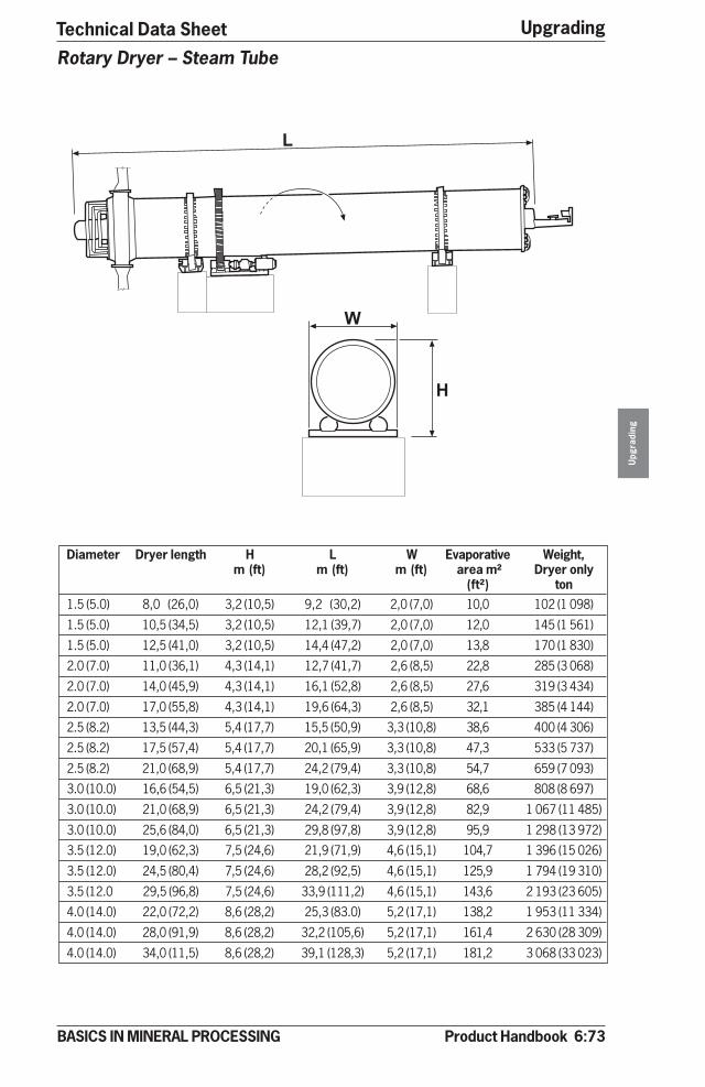
Product Handbook 6:73
Upgrading
Upg
radi
ng
BASICS IN MINERAL PROCESSING
Technical Data Sheet
�
�
Rotary Dryer – Steam Tube
Diameter Dryer length H L W Evaporative Weight,m (ft) m (ft) m (ft) area m² Dryer only
(ft²) ton1.5 (5.0) 8,0 (26,0) 3,2 (10,5) 9,2 (30,2) 2,0 (7,0) 10,0 102 (1 098)
1.5 (5.0) 10,5 (34,5) 3,2 (10,5) 12,1 (39,7) 2,0 (7,0) 12,0 145 (1 561)
1.5 (5.0) 12,5 (41,0) 3,2 (10,5) 14,4 (47,2) 2,0 (7,0) 13,8 170 (1 830)
2.0 (7.0) 11,0 (36,1) 4,3 (14,1) 12,7 (41,7) 2,6 (8,5) 22,8 285 (3 068)
2.0 (7.0) 14,0 (45,9) 4,3 (14,1) 16,1 (52,8) 2,6 (8,5) 27,6 319 (3 434)
2.0 (7.0) 17,0 (55,8) 4,3 (14,1) 19,6 (64,3) 2,6 (8,5) 32,1 385 (4 144)
2.5 (8.2) 13,5 (44,3) 5,4 (17,7) 15,5 (50,9) 3,3 (10,8) 38,6 400 (4 306)
2.5 (8.2) 17,5 (57,4) 5,4 (17,7) 20,1 (65,9) 3,3 (10,8) 47,3 533 (5 737)
2.5 (8.2) 21,0 (68,9) 5,4 (17,7) 24,2 (79,4) 3,3 (10,8) 54,7 659 (7 093)
3.0 (10.0) 16,6 (54,5) 6,5 (21,3) 19,0 (62,3) 3,9 (12,8) 68,6 808 (8 697)
3.0 (10.0) 21,0 (68,9) 6,5 (21,3) 24,2 (79,4) 3,9 (12,8) 82,9 1 067 (11 485)
3.0 (10.0) 25,6 (84,0) 6,5 (21,3) 29,8 (97,8) 3,9 (12,8) 95,9 1 298 (13 972)
3.5 (12.0) 19,0 (62,3) 7,5 (24,6) 21,9 (71,9) 4,6 (15,1) 104,7 1 396 (15 026)
3.5 (12.0) 24,5 (80,4) 7,5 (24,6) 28,2 (92,5) 4,6 (15,1) 125,9 1 794 (19 310)
3.5 (12.0 29,5 (96,8) 7,5 (24,6) 33,9 (111,2) 4,6 (15,1) 143,6 2 193 (23 605)
4.0 (14.0) 22,0 (72,2) 8,6 (28,2) 25,3 (83.0) 5,2 (17,1) 138,2 1 953 (11 334)
4.0 (14.0) 28,0 (91,9) 8,6 (28,2) 32,2 (105,6) 5,2 (17,1) 161,4 2 630 (28 309)
4.0 (14.0) 34,0 (11,5) 8,6 (28,2) 39,1 (128,3) 5,2 (17,1) 181,2 3 068 (33 023)

6:74 Product Handbook
UpgradingU
pgra
ding
BASICS IN MINERAL PROCESSING
�
� �
�
Model H mm (inch) L mm (inch) W mm (inch) Weight Powerton kW/hp
S 710-4* 335 (13) 4 140 (163) 310 (12) 0,8 0,55-1,1/075-1,5
S 714-4 335 (13) 5 360 (211) 310 (12) 1,0 0,55-1,1/0,75-1,5
D 710-4 335 (13) 4 170 (164) 460 (18) 1,2 0,55-2,2/0,75-3
D 714-4 335 (13) 5 390 (212) 460 (18) 1,5 0,55-2,2/0,75-3
S 1210-5 565 (22) 4 270 (168) 460 (18) 1,3 1,1-4/1,5-5
S 1218-5 565 (22) 6 710 (264) 460 (18) 1,9 1,1-4/1,5-5
D 1210-5 565 (22) 4 550 (179) 720 (28) 2,3 1,5-5,5/2-7,5
D 1218-5 565 (22) 6 990 (275) 720 (28) 2,5 1,5-5,5/2-7,5
S 1616-6 641 (25) 6 200 (244) 560 (22) 2,3 2,2-5,5/3-7,5
S 1618-6 641 (25) 6 810 (268) 560 (22) 2,4 2,2-5,5/3-7,5
D 1616-6 641 (25) 6 510 (256) 890 (35) 3,8 2,2-7,5/3-10
D 1618-6 641 (25) 7 120 (280) 890 (35) 4,2 2,2-7,5/3-10
S 2414-6 881 (35) 5 720 (225) 770 (30) 3,3 2,2-7,5/3-10
S 2424-6 881 (35) 8 770 (345) 770 (30) 5,1 4-11/5-15
D 2414-6 881 (35) 6 150 (242) 1 220 (48) 6,4 4-11/5-15
D 2424-6 881 (35) 9 200 (362) 1 220 (48) 6,9 5,5-15/7,5-20
Q 2414-6 881 (35) 6 760 (266) 2 160 (85) 12,0 7,5-30/10-40
Q 2424-6 881 (35) 9 200 (262) 2 160 (85) 17,0 7,5-37/10-50
S 3020-7 1 092 (43) 8 260 (325) 970 (38) 10,2 5,5-15/7,5-20
S 3028-7 1 092 (43) 10 700 (421) 970 (38) 13,0 7,5-22/10-30
D 3020-7 1 092 (43) 8 740 (344) 1 600 (63) 16,8 7,5-18/10-25
D 3028-7 1 092 (43) 11 180 (440) 1 600 (63) 21,6 11-22/15-30
Q 3020-7 1 092 (43) 8 740 (344) 2 720 (107) 33,2 15-37/20-50
Q 3028-7 1 092 (43) 11 180 (440) 2 720 (107) 42,9 8,5-55/25-75
*S 710-4, S = single screw, 7 = screw diameter, inch, 10 = screw length 10ft, – 4= screw pitch 4 inch
D = double screw, Q = Quadruple screw
Indirect Heat Screw Dryer – Holo-Flite®
Technical Data Sheet
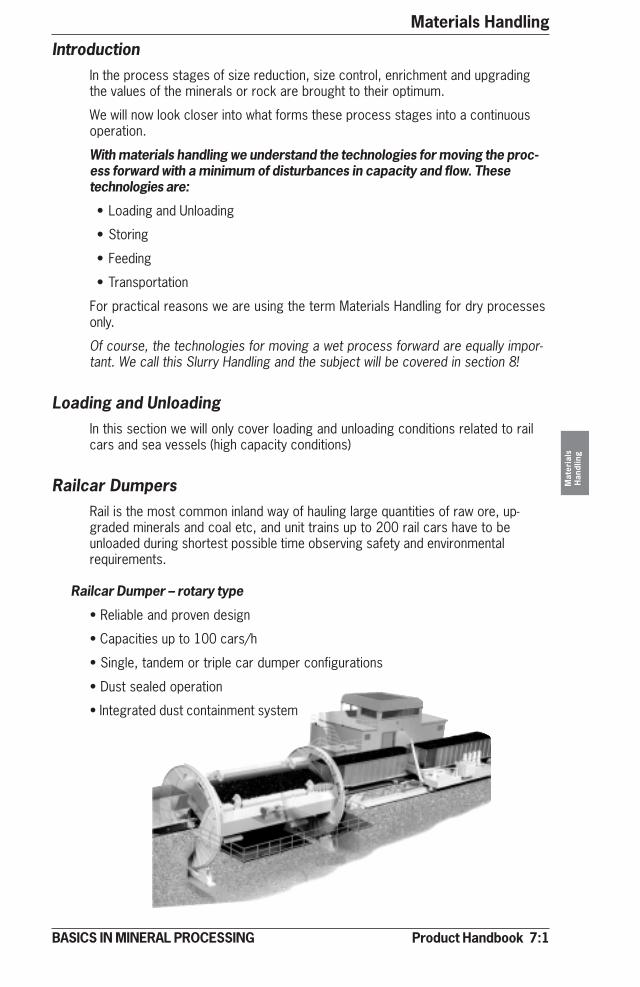
Product Handbook 7:1
Materials Handling
Mat
eria
lsH
andl
ing
BASICS IN MINERAL PROCESSING
IntroductionIn the process stages of size reduction, size control, enrichment and upgradingthe values of the minerals or rock are brought to their optimum.
We will now look closer into what forms these process stages into a continuousoperation.
With materials handling we understand the technologies for moving the proc-ess forward with a minimum of disturbances in capacity and flow. Thesetechnologies are:
• Loading and Unloading
• Storing
• Feeding
• Transportation
For practical reasons we are using the term Materials Handling for dry processesonly.
Of course, the technologies for moving a wet process forward are equally impor-tant. We call this Slurry Handling and the subject will be covered in section 8!
Loading and UnloadingIn this section we will only cover loading and unloading conditions related to railcars and sea vessels (high capacity conditions)
Railcar DumpersRail is the most common inland way of hauling large quantities of raw ore, up-graded minerals and coal etc, and unit trains up to 200 rail cars have to beunloaded during shortest possible time observing safety and environmentalrequirements.
Railcar Dumper – rotary type
• Reliable and proven design
• Capacities up to 100 cars/h
• Single, tandem or triple car dumper configurations
• Dust sealed operation
• Integrated dust containment system

7:2 Product Handbook
Materials HandlingM
ater
ials
Han
dlin
g
BASICS IN MINERAL PROCESSING
Railcar Dumper – “Crescent” design
• Low in energy (rotation axis close to gravity centre of loaded cars).• Hopper position close to rail track• Hydraulic car clamping system (closed loop)• Rate of unloading 60 cars/h and line
Rail car Dumper - Rotaside® type
• Hopper position at the side of rail track gives simplified installation.• Proven and simple design• Low in maintenance• Rate of unloading 12 cars/h
Train PositionersA Train Positioner has to have a high utilisation capability to enable it to preciselyposition blocks of 1-10 railcars up to heavy train in excess of 200 railcars using apreset velocity pattern. In duties ranging from 5 to 90 cars unloading per hourthere are a number of options for Positioners.
System
Side Arm System (rack and piniondrive), see picture nest page
Reversible Hydraulic IndexerSystem
Wire Rope Car Pullers
Vertical Capstan System
Double side Arm System (Gemini®)
Unloading Duty
Heavy 100 car, or more, trains athigh capacity
25 ton pull, 5-15 cars/hour
From 2-12 ton pull at variablespeeds
Manual operation - limited pull anddistances
For very high unloading rates
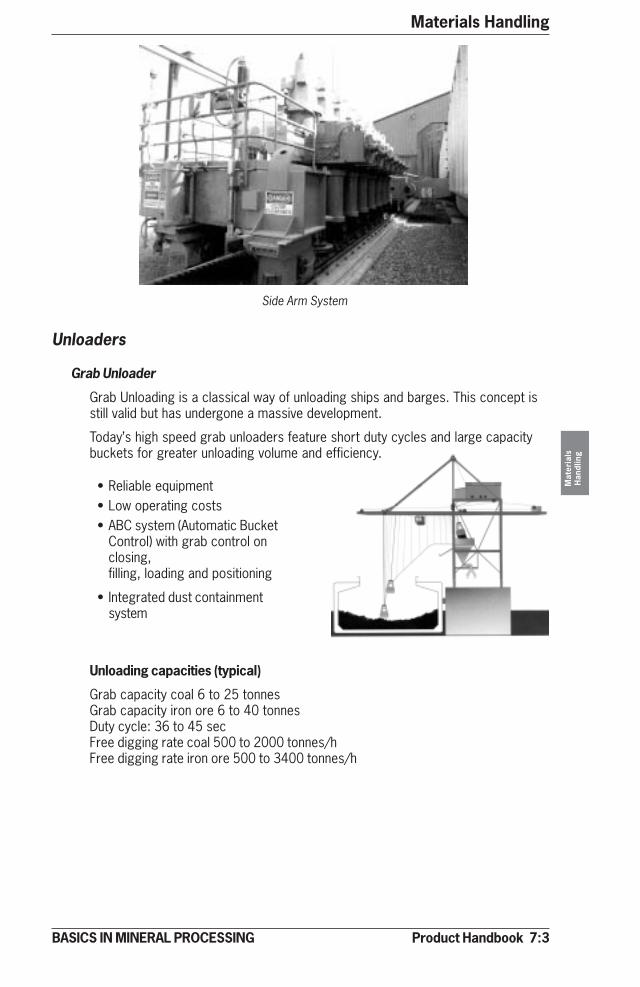
Product Handbook 7:3
Materials Handling
Mat
eria
lsH
andl
ing
BASICS IN MINERAL PROCESSING
Unloaders
Grab Unloader
Grab Unloading is a classical way of unloading ships and barges. This concept isstill valid but has undergone a massive development.
Today’s high speed grab unloaders feature short duty cycles and large capacitybuckets for greater unloading volume and efficiency.
Side Arm System
• Reliable equipment• Low operating costs• ABC system (Automatic Bucket
Control) with grab control onclosing,filling, loading and positioning
• Integrated dust containmentsystem
Unloading capacities (typical)
Grab capacity coal 6 to 25 tonnesGrab capacity iron ore 6 to 40 tonnesDuty cycle: 36 to 45 secFree digging rate coal 500 to 2000 tonnes/hFree digging rate iron ore 500 to 3400 tonnes/h
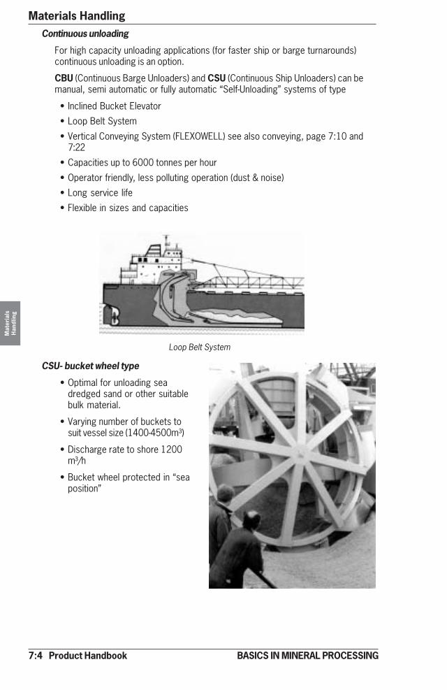
7:4 Product Handbook
Materials HandlingM
ater
ials
Han
dlin
g
BASICS IN MINERAL PROCESSING
Continuous unloading
For high capacity unloading applications (for faster ship or barge turnarounds)continuous unloading is an option.
CBU (Continuous Barge Unloaders) and CSU (Continuous Ship Unloaders) can bemanual, semi automatic or fully automatic “Self-Unloading” systems of type
• Inclined Bucket Elevator
• Loop Belt System
• Vertical Conveying System (FLEXOWELL) see also conveying, page 7:10 and7:22
• Capacities up to 6000 tonnes per hour
• Operator friendly, less polluting operation (dust & noise)
• Long service life
• Flexible in sizes and capacities
Loop Belt System
CSU- bucket wheel type
• Optimal for unloading seadredged sand or other suitablebulk material.
• Varying number of buckets tosuit vessel size (1400-4500m³)
• Discharge rate to shore 1200m³/h
• Bucket wheel protected in “seaposition”
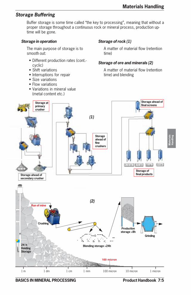
Product Handbook 7:5
Materials Handling
Mat
eria
lsH
andl
ing
BASICS IN MINERAL PROCESSING
Storage BufferingBuffer storage is some time called “the key to processing”, meaning that without aproper storage throughout a continuous rock or mineral process, production up-time will be gone.
1 m 1 dm 1 cm 1 mm 100 micron 10 micron 1 micron
100 micron
Blending storage >24h
Productionstorage >8h
Run of mine
Grinding
Crushing
Storage in operation
The main purpose of storage is tosmooth out:
• Different production rates (cont.-cyclic)
• Shift variations• Interruptions for repair• Size variations• Flow variations• Variations in mineral value
(metal content etc.)
Storage of rock (1)
A matter of material flow (retentiontime)
Storage of ore and minerals (2)
A matter of material flow (retentiontime) and blending
Storage atprimarycrusher
Storageahead offinecrushers
Storage ahead ofsecondary crusher
Storage ahead offinal screens
Storage offinal products
24 hHoistingStorage
(1)
(2)
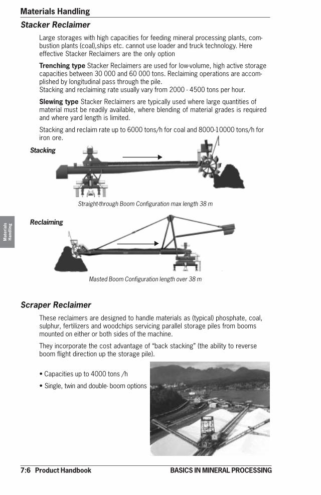
7:6 Product Handbook
Materials HandlingM
ater
ials
Han
dlin
g
BASICS IN MINERAL PROCESSING
Stacker ReclaimerLarge storages with high capacities for feeding mineral processing plants, com-bustion plants (coal),ships etc. cannot use loader and truck technology. Hereeffective Stacker Reclaimers are the only option
Trenching type Stacker Reclaimers are used for low-volume, high active storagecapacities between 30 000 and 60 000 tons. Reclaiming operations are accom-plished by longitudinal pass through the pile.Stacking and reclaiming rate usually vary from 2000 - 4500 tons per hour.
Slewing type Stacker Reclaimers are typically used where large quantities ofmaterial must be readily available, where blending of material grades is requiredand where yard length is limited.
Stacking and reclaim rate up to 6000 tons/h for coal and 8000-10000 tons/h foriron ore.
Reclaiming
Masted Boom Configuration length over 38 m
Stacking
Straight-through Boom Configuration max length 38 m
Scraper ReclaimerThese reclaimers are designed to handle materials as (typical) phosphate, coal,sulphur, fertilizers and woodchips servicing parallel storage piles from boomsmounted on either or both sides of the machine.
They incorporate the cost advantage of “back stacking” (the ability to reverseboom flight direction up the storage pile).
• Capacities up to 4000 tons /h
• Single, twin and double- boom options
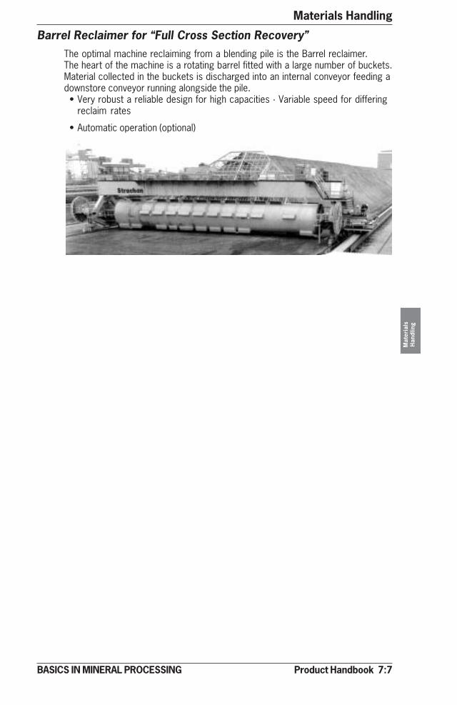
Product Handbook 7:7
Materials Handling
Mat
eria
lsH
andl
ing
BASICS IN MINERAL PROCESSING
Barrel Reclaimer for “Full Cross Section Recovery”The optimal machine reclaiming from a blending pile is the Barrel reclaimer.The heart of the machine is a rotating barrel fitted with a large number of buckets.Material collected in the buckets is discharged into an internal conveyor feeding adownstore conveyor running alongside the pile.• Very robust a reliable design for high capacities · Variable speed for differing
reclaim rates
• Automatic operation (optional)

7:8 Product Handbook
Materials HandlingM
ater
ials
Han
dlin
g
BASICS IN MINERAL PROCESSING
Vibrating (eccentric shaft) Vibrating (unbalance motor)Belt
Primary Feeders
Apron Vibrating
Capacity700 - 5000 t/h
Capacity300 - 1200 t/h
Capacity30 - 600 t/h
Capacity80 - 350 t/h
Capacity55 - 460 t/h
Capacityabove20 t/h
}VIBRATING (unbalanced motor )max feed size approx. 400 mm
VIBRATING (Electromagnetic )max feed size approx. 150 mm
Tolerantto stickymaterial
Precisein feeding
Precise in feedingTolerant to stickymaterial
Capacityabove50 t/h
Capacity0 - 350 t/h
Nottolerantto stickymaterial
�
VIBRATING (eccentric shaft)max feed size approx. 1.0 m }
}}}
FeedingFeeders are necessary whenever we want to deliver a uniform flow of dry ormoist fractions of rock or minerals.Generally they are categorised by the size of material to be fed, see below.
Feeding vs Feed Sizes
Size 1m 1 dm 1 cm 1 mm 100 micron 10 micron 1 micron
8
APRONmax feed size approx. 2.0 m
Sensitive against fines– 5 mm precise in feeding
�
�
�
�
“In circuit” feeders
See also data sheets 7:14 - 7:19.
BELTmax feed size approx. 50 mm

Product Handbook 7:9
Materials Handling
Mat
eria
lsH
andl
ing
BASICS IN MINERAL PROCESSING
Wobbler feeders
Feeding and scalping - when things get sticky!
Openings between elipticbars remain constant
Fines, mud or dirt dropthrough the openings
Oversize moves forward
Size range
• See apron and table feeders
Applications
• Wet and sticky for:
metallic, industrial and construc-tion minerals
Pitch (scalping)
• Fixed and adjustable
Capacity range
• Up to 3 500 t/h (5 sizes)
Pitch
Wear Part
Tonnage and size Distance Inclination
ConveyingIn this section we will focus on mineral mass flow by conveying, by far the domi-nating method when transporting dry material in a mineral processing operation.
Conveyor – general
Conveyors are selected from 4 key parameters:• Tonnage• Size of material• Inclination• Distance
We also must consider wear in operationand the environment (dust, heat, oil or chemicals etc)
See data sheet 7:20.
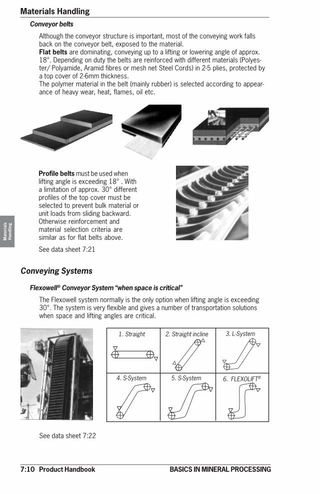
7:10 Product Handbook
Materials HandlingM
ater
ials
Han
dlin
g
BASICS IN MINERAL PROCESSING
Conveying Systems
Flexowell® Conveyor System “when space is critical”
The Flexowell system normally is the only option when lifting angle is exceeding30°. The system is very flexible and gives a number of transportation solutionswhen space and lifting angles are critical.
1. Straight 2. Straight incline 3. L-System
4. S-System 5. S-System 6. FLEXOLIFT®
Profile belts must be used whenlifting angle is exceeding 18° . Witha limitation of approx. 30° differentprofiles of the top cover must beselected to prevent bulk material orunit loads from sliding backward.Otherwise reinforcement andmaterial selection criteria aresimilar as for flat belts above.
See data sheet 7:21
Conveyor belts
Although the conveyor structure is important, most of the conveying work fallsback on the conveyor belt, exposed to the material.Flat belts are dominating, conveying up to a lifting or lowering angle of approx.18°. Depending on duty the belts are reinforced with different materials (Polyes-ter/ Polyamide, Aramid fibres or mesh net Steel Cords) in 2-5 plies, protected bya top cover of 2-6mm thickness.The polymer material in the belt (mainly rubber) is selected according to appear-ance of heavy wear, heat, flames, oil etc.
See data sheet 7:22
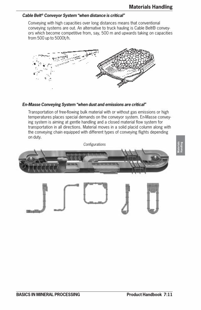
Product Handbook 7:11
Materials Handling
Mat
eria
lsH
andl
ing
BASICS IN MINERAL PROCESSING
Cable Belt® Conveyor System “when distance is critical”
Conveying with high capacities over long distances means that conventionalconveying systems are out. An alternative to truck hauling is Cable Belt® convey-ors which become competitive from, say, 500 m and upwards taking on capacitiesfrom 500 up to 5000t/h.
En-Masse Conveying System “when dust and emissions are critical”
Transportation of free-flowing bulk material with or without gas emissions or hightemperatures places special demands on the conveyor system. En-Masse convey-ing system is aiming at gentle handling and a closed material flow system fortransportation in all directions. Material moves in a solid placid column along withthe conveying chain equipped with different types of conveying flights dependingon duty.
Configurations
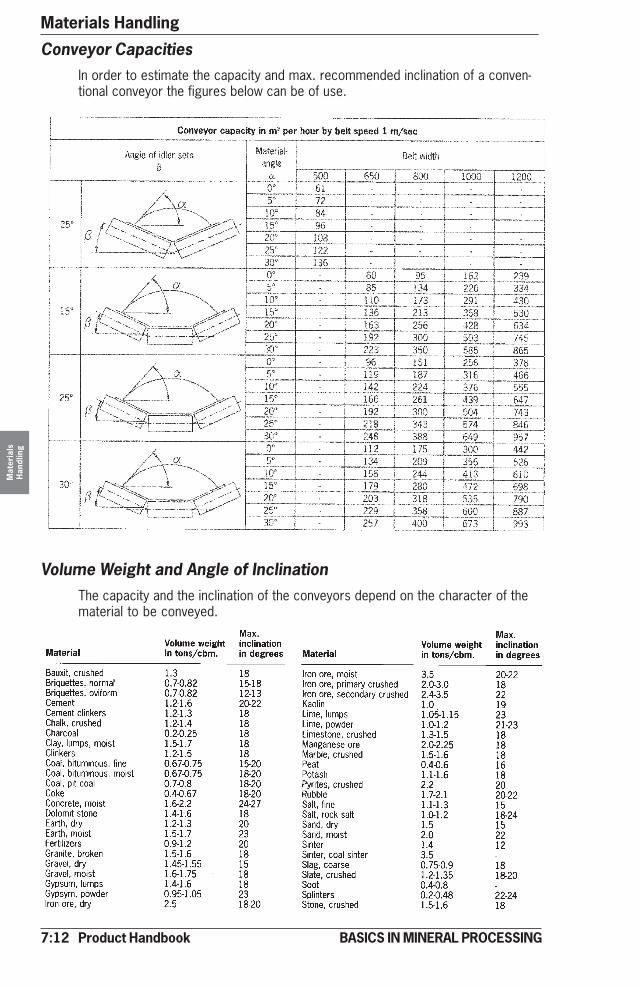
7:12 Product Handbook
Materials HandlingM
ater
ials
Han
dlin
g
BASICS IN MINERAL PROCESSING
Conveyor CapacitiesIn order to estimate the capacity and max. recommended inclination of a conven-tional conveyor the figures below can be of use.
Volume Weight and Angle of InclinationThe capacity and the inclination of the conveyors depend on the character of thematerial to be conveyed.
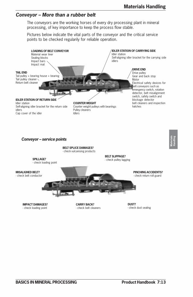
Product Handbook 7:13
Materials Handling
Mat
eria
lsH
andl
ing
BASICS IN MINERAL PROCESSING
Conveyor – More than a rubber beltThe conveyors are the working horses of every dry processing plant in mineralprocessing, of key importance to keep the process flow stable.
Pictures below indicate the vital parts of the conveyor and the critical servicepoints to be checked regularily for reliable operation.
DRIVE ENDDrive pulleyGear and back stopMotorElectrical safety devices forbelt conveyors such asemergency switch, rotationdetector, belt misalignmentswitch, safety switch andblockage detectorbelt cleaners and inspectionhatches
TAIL ENDTail pulley + bearing house + bearingTail pulley cleanerReturn belt cleaner
LOADING OF BELT CONVEYORMaterial wear linerSealing blocksImpact barsImpact mat
COUNTER WEIGHTCounter weight pulleys with beariingsPulley cleanersIdlers
IDLER STATION OF CARRYING SIDEIdler stationSelf-aligning idler bracket for the carrying sideidlers
IDLER STATION OF RETURN SIDEIdler stationSelf-aligning idler bracket for the return sideidlersCap cover of the idler
Conveyor – service points
DUST?- check dust sealing
BELT SLIPPAGE?- check pulley lagging
CARRY BACK?- check belt cleaners
IMPACT DAMAGES?- check loading point
SPILLAGE?- check loading point
MISALIGNED BELT?- check belt conductor
BELT SPLICE DAMAGES?- check vulcanising products
PINCHING ACCIDENTS?- check return roll guard

7:14 Product Handbook
Materials HandlingM
ater
ials
Han
dlin
g
BASICS IN MINERAL PROCESSING
Technical Data Sheet
Model AF 4 AF 5 AF 8 AF 10 AF 12 AF 14 AF 16 AF 18Width (pan) Weight* Weight* Weight* Weight* Weight* Weight* Weight* Weight*mm/inch ton/lbs ton/lbs ton/lbs ton/lbs ton/lbs ton lbs ton/lbs ton/lbs
610/24 4,1/9 280
762/30 4,3/9 734 5,1/11 580
914/36 4,6/10 300 5,8/1 306
107/42 4,8/10 840 6,3/14 020
1219/48 5,6/12 610 6,6/14 850 8,6/19 160
1372/54 6,0/13 430 7,1/15 840 9,1/20 440 11,8/26 470
1524/60 6,5/14 480 7,5/16 770 9,9/22 080 12,7/28 340 17,1/38 360
1829/72 7,6/16 930 8,8/19 600 11,5/25 870 13,9/31 080 18,4/41 120 22,7/50 800
2134/84 8,1/18 070 9,8/22 060 12,8/28 630 16,2/36 260 19,8/44 330 25,3/56 780 51,1/11 4400
2438/96 8,8/19 650 11,4/25 450 14,2/31 850 17,5/39 120 21,1/47 210 27,0/60 550 56,1/12 5630
2743/108 9,8/21 860 12,5/27 960 15,1/33 750 18,5/41 480 24,3/54 540 32,0/71 770 62,3/13 9650 66,3/14 6220
3048/120 10,7/24 010 13,4/29 950 16,1/36 100 21,3/47 710 25,6/57 442 32,9/73 730 63,9/14 3240 65,9/14 7660
3353/132 34,6/77 540 66,8/14 9730 68,7/15 3880
*Approx, weight of an Apron feeder, length 3m (10ft) excl. load, skirts, chutes etc. For each additional feet (or 0,3 m) add 7
%in weight.Feed size approx, 50% of pan width. Capacity range 500 - 12 000 t/h
Model AF 4 AF 5 AF 8 AF 10 AF 12 AF 14 AF 16 AF 18
Chain pitch 140 (5,5) 171 (6,8) 202 (8,0) 216 (8,5) 229 (9,0) 260 (10,3) 260 (10,3) 317 (12,5) mm (inch)
Main beam Width pan Width pan Width pan Width pan Width pan Width pan Width pan Width panwidth mm (inch)+356 (14) +45 (18) +45 (18) +45 (18) +508 (20) +584 (23) +584 (23) +610 (24)
Feeder suitable suitable suitable suitable suitable suitable suitable suitablelength
Height (H) 889 (35) 1 041 (41) 1 268 (50) 1 372 (54) 1 625 (64) 1 753 (69) 1 803 (71) on sitemm(inch) demands
Feeder – Apron
�����������
�
��
������
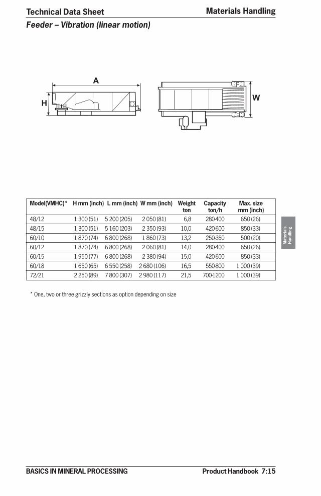
Product Handbook 7:15
Materials Handling
Mat
eria
lsH
andl
ing
BASICS IN MINERAL PROCESSING
Technical Data Sheet
Model(VMHC)* H mm (inch) L mm (inch) W mm (inch) Weight Capacity Max. sizeton ton/h mm (inch)
48/12 1 300 (51) 5 200 (205) 2 050 (81) 6,8 280-400 650 (26)
48/15 1 300 (51) 5 160 (203) 2 350 (93) 10,0 420-600 850 (33)
60/10 1 870 (74) 6 800 (268) 1 860 (73) 13,2 250-350 500 (20)
60/12 1 870 (74) 6 800 (268) 2 060 (81) 14,0 280-400 650 (26)
60/15 1 950 (77) 6 800 (268) 2 380 (94) 15,0 420-600 850 (33)
60/18 1 650 (65) 6 550 (258) 2 680 (106) 16,5 550-800 1 000 (39)
72/21 2 250 (89) 7 800 (307) 2 980 (117) 21,5 700-1200 1 000 (39)
* One, two or three grizzly sections as option depending on size
Feeder – Vibration (linear motion)
�
��

7:16 Product Handbook
Materials HandlingM
ater
ials
Han
dlin
g
BASICS IN MINERAL PROCESSING
Technical Data Sheet
Model (VMO) H mm (inch) L mm (inch) W mm/inch Weight Capacity*ton ton/h*
15/6.5 - 3014 780 (31) 1 770 (70) 1 260/50 0,5 30-160
17.5/8 - 40 830 (33) 2 050 (81) 1 410/56 0,7 40-210
20/10 - 40 950 (37) 2 300 (91) 1 670/66 1,1 60-320
30/10 - 40 1 000 (39) 3 300 (130) 1 670/66 1,5 60-300
30/10 - 45 1 000 (39) 3 300 (130) 1 720/68 1,7 100-500
20/12.5 - 45 950 (37) 2 300 (91) 1 030/41 1,3 90-550
25/12.5 - 45 1 050 (41) 2 790 (110) 1 970/76 1,8 90-550
* Capacity at 8° inclination, feed moist sand 1-7mm (16-3 mesh)
Feeders – Unbalanced motor
�
�
�

Product Handbook 7:17
Materials Handling
Mat
eria
lsH
andl
ing
BASICS IN MINERAL PROCESSING
Model (VMO) H mm (inch) L mm (inch) W mm (inch) Weight Capacity*ton ton/h
10/4.5 1 050 (41) 1 000 (39) 450 (18) 0,64 180
15/4.5 1 050 (41) 1 500 (59) 450 (18) 0,71 180
20/4.5 1 050 (41) 2 000 (78) 450 (18) 0,80 180
10/6 1 200 (47) 1 000 (39) 600 (24) 0,77 250
15/6 1 200 (47) 1 500 (59) 600 (24) 0,89 250
20/6 1 200 (47) 2 000 (78) 600 (24) 0,94 250
10/8 1 200 (47) 1 000 (39) 800 (31) 0,98 350
15/8 1 200 (47( 1 500 (59) 800 (31) 1,10 350
20/8 1 200 (47) 2 000 (78) 800 (31) 1,20 350
* Max feed size 50 mm (2”)
Feeder – Belt
� �
�
Technical Data Sheet
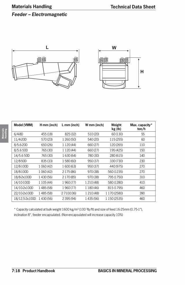
7:18 Product Handbook
Materials HandlingM
ater
ials
Han
dlin
g
BASICS IN MINERAL PROCESSING
� �
�
Model (VMM) H mm (inch) L mm (inch) W mm (inch) Weight Max. capacity*kg (lb) ton/h
6/4-8D 455 (18) 825 (32) 510 (20) 60 (130) 55
11/4-20D 570 (23) 1 260 (50) 540 (20) 115 (255) 60
8/5.6-20D 650 (26) 1 120 (44) 660 (27) 120 (265) 110
8/5.6 50D 765 (30) 1 120 (44) 660 (27) 195 (425) 150
14/5.6 50D 765 (30) 1 630 (64) 780 (30) 280 (615) 140
12/8-50D 835 (33) 1 580 (60) 950 (37) 330 (730) 230
12/8-100D 1 060 (42) 1 600 (63) 950 (37) 440 (975) 270
18/8-100D 1 060 (42) 2 175 (86) 970 (38) 560 (1235) 270
18/8-2x100D 1 430 (56) 2 170 (85) 970 (38) 795 (1750) 310
14/10-100D 1 105 (44) 1 960 (77) 1 210 (48) 580 (1280) 410
14/10-2x100D 1 485 (58) 1 960 (77) 1 180 (46) 815 (1795) 460
22/10-2x100D 1 485 (58) 2 710(106) 1 210 (48) 1 170 (2580) 390
18/12.5-2x100D 1 430 (56) 2 395 (94) 1 435 (56) 1 150 (2535) 460
* Capacity calculated at bulk weight 1600 kg/m³ (100 ³lb/ft) and size of feed 16-25mm (0.75-1”),
inclination 8°, feeder encapsulated. (Non-encapsulated will increase capacity 10%)
Feeder – Electromagnetic
Technical Data Sheet
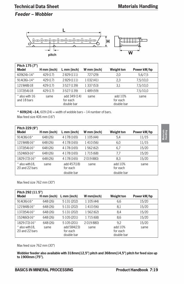
Product Handbook 7:19
Materials Handling
Mat
eria
lsH
andl
ing
BASICS IN MINERAL PROCESSING
�
�
���� �
Pitch 175 (7”)Model H mm (inch) L mm (inch) W mm (inch) Weight ton Power kW/hp609(24)–14* 429 (17) 2 829 (111) 727 (29) 2,0 5,6/7,5
914(36)–14* 429 (17) 2 829 (111) 1 032 (41) 2,3 7,5/10,0
1219(48)-18 429 (17) 3 527 (139) 1 337 (53) 3,1 7,5/10,0
1372(54)-18 429 (17) 3 527 (139) 1 489 (59) 7,5/10,0
* also with 16 same add 349 (14) same add 10% sameand 18 bars for each for each
double bar double bar
* 609(24) –14, 609 (24) = width of wobble bars – 14 number of bars.Max feed size 406 mm (16”)
Pitch 229 (9”)Model H mm (inch) L mm (inch) W mm (inch) Weight ton Power kW/hp914(36)-16* 648 (26) 4 178 (165) 1 105 (44) 5,4 11/15
1219(48)-16* 648 (26) 4 178 (165) 1 410 (56) 6,0 11/15
1372(54)-16* 648 (26) 4 178 (165) 1 562 (62) 6,7 15/20
1524(60)-16* 648 (26) 4 178 (165) 1 715 (68) 7,7 15/20
1829 (72)-16* 648 (26) 4 178 (165) 2 019 880) 8,3 15/20
* also with18, same add 457(18) same add 10% same20 and 22 bars for each for each
double bar double bar
Max feed size 762 mm (30”)
Pitch 292 (11.5”)Model H mm (inch) L mm (inch) W mm(inch) Weight ton Power kW/hp914(36)-16* 648 (26) 5 131 (202) 1 105 (44) 6,6 15/20
1219(48)-16* 648 (26) 5 131 (202) 1 410 (56) 8,1 15/20
1372(54)-16* 648 (26) 5 131 (202) 1 562 (62) 8,4 15/20
1524(60)-16* 648 (26) 5 105 (201) 1 715 (68) 8,6 15/20
1829 (72)-16* 648 (26) 5 105 (201) 2 019 880) 9,2 15/20* also with18, same add 584(23) same add 10% same20 and 22 bars for each for each
double bar double bar
Max feed size 762 mm (30”)
Wobbler feeder also available with 318mm(12,5”) pitch and 368mm(14,5”) pitch for feed size upto 1900mm (75”).
Feeder – Wobbler
Technical Data Sheet
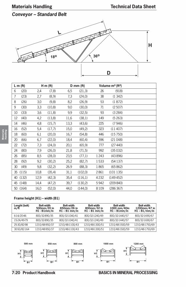
7:20 Product Handbook
Materials HandlingM
ater
ials
Han
dlin
g
BASICS IN MINERAL PROCESSING
L m (ft) H m (ft) D mm (ft) Volume m³ (ft³)6 (20) 2,4 (7,8) 6,5 (21,3) 26 (918)
7 (23) 2,7 (8,9) 7,3 (24,0) 38 (1 342)
8 (26) 3,0 (9,8) 8,2 (26,9) 53 (1 872)
9 (30) 3,3 (10,8) 9,0 (30,0) 71 (2 507)
10 (33) 3,6 (11,8) 9,9 (32,5) 93 (3 284)
12 (40) 4,2 (13,8) 11,6 (38,1) 149 (5 263)
14 (46) 4,8 (15,7) 13,3 (43,6) 225 (7 946)
16 (52) 5,4 (17,7) 15,0 (49,2) 323 (11 407)
18 (60) 6,1 (20,0) 16,7 (54,8) 446 (15 750)
20 (66) 6,7 (22,0) 18,4 (60,4) 596 (21 048)
22 (72) 7,3 (24,0) 20,1 (65,9) 777 (27 440)
24 (80) 7,9 (26,0) 21,8 (71,5) 992 (35 032)
26 (85) 8,5 (28,0) 23,5 (77,1) 1 243 (43 896)
28 (92) 9,2 (30,2) 25,2 (82,7) 1 533 (54 137)
30 (49) 9,8 (32,2) 26.9 (88,3) 1 865 (65 862)
35 (115) 10,8 (35,4) 31,1 (102,0) 2 861 (101 135)
40 (132) 12,9 (42,3) 35,4 (116,1) 4 232 (149 452)
45 (148) 14,4 (47,2) 39,7 (130,2) 5 942 (209 840)
50 (164) 16,0 (52,0) 44,0 (144,0) 8 109 (286 367)
Frame height (H1) – width (B1)
Lenght (belt) Belt width Belt width Belt width Belt width Belt widthm/ft 500mm/20 in 650mm/26 in 800mm/32 in 1000 mm/40in 1200mm/47 in
H1 - B1mm/in H1 – B1 mm/in H1 – B1 mm/in H1 – B1mm/in H1 – B1/mm/in
6-14/20-46 800/32-890/35 800/32-1040/41 800/32-1240/49 800/32-1440/57 800/32-1690/67
15-24/49-79 800/32-890/35 800/32-1040/41 800/32-1240/49 800/32-1440/57 800/32-1690/67
25-30/82-98 1210/48-950/37 1210/48-1100/43 1210/48-1300/51 1210/48-1500/59 1210/48-1750/69
30-50/82-164 1210/48-950/37 1210/48-1100/43 1210/48-1300/51 1210/48-1500/59 1210/48-1750/69
Conveyor – Standard Belt
�
�
�� ��
��
��
��
��
������������
��
��
������
��
��
�������
��
��
�������
Technical Data Sheet
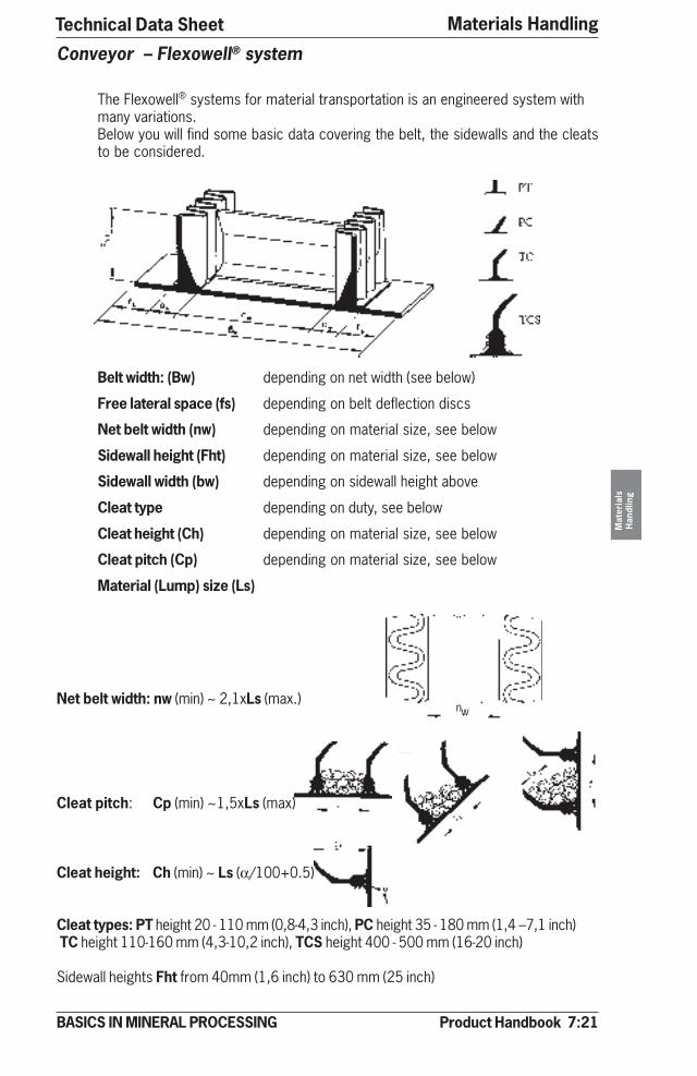
Product Handbook 7:21
Materials Handling
Mat
eria
lsH
andl
ing
BASICS IN MINERAL PROCESSING
Conveyor – Flexowell® system
The Flexowell® systems for material transportation is an engineered system withmany variations.Below you will find some basic data covering the belt, the sidewalls and the cleatsto be considered.
Belt width: (Bw) depending on net width (see below)
Free lateral space (fs) depending on belt deflection discs
Net belt width (nw) depending on material size, see below
Sidewall height (Fht) depending on material size, see below
Sidewall width (bw) depending on sidewall height above
Cleat type depending on duty, see below
Cleat height (Ch) depending on material size, see below
Cleat pitch (Cp) depending on material size, see below
Material (Lump) size (Ls)
Net belt width: nw (min) ~ 2,1xLs (max.)
Cleat pitch: Cp (min) ~1,5xLs (max)
Cleat height: Ch (min) ~ Ls (α/100+0.5)
Cleat types: PT height 20 - 110 mm (0,8-4,3 inch), PC height 35 - 180 mm (1,4 –7,1 inch) TC height 110-160 mm (4,3-10,2 inch), TCS height 400 - 500 mm (16-20 inch)
Sidewall heights Fht from 40mm (1,6 inch) to 630 mm (25 inch)
nw
Technical Data Sheet
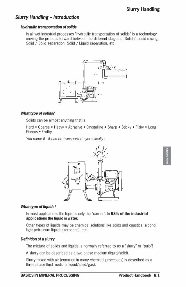
Product Handbook 8:1
Slurry Handling
Slur
ry h
andl
ing
BASICS IN MINERAL PROCESSING
Slurry Handling – Introduction
Hydraulic transportation of solids
In all wet industrial processes ”hydraulic transportation of solids” is a technology,moving the process forward between the different stages of Solid / Liquid mixing,Solid / Solid separation, Solid / Liquid separation, etc.
What type of solids?
Solids can be almost anything that is
Hard • Coarse • Heavy • Abrasive • Crystalline • Sharp • Sticky • Flaky • LongFibrous • Frothy
You name it - it can be transported hydraulically !
What type of liquids?
In most applications the liquid is only the ”carrier”. In 98% of the industrialapplications the liquid is water.
Other types of liquids may be chemical solutions like acids and caustics, alcohol,light petroleum liquids (kerosene), etc.
Definition of a slurry
The mixture of solids and liquids is normally referred to as a ”slurry” or “pulp”!
A slurry can be described as a two phase medium (liquid/solid).
Slurry mixed with air (common in many chemical processes) is described as athree phase fluid medium (liquid/solid/gas).
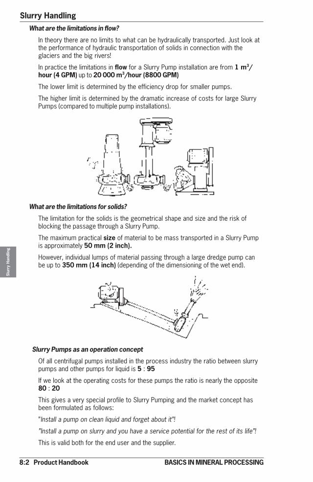
8:2 Product Handbook
Slurry HandlingSl
urry
Han
dlin
g
BASICS IN MINERAL PROCESSING
What are the limitations in flow?
In theory there are no limits to what can be hydraulically transported. Just look atthe performance of hydraulic transportation of solids in connection with theglaciers and the big rivers!
In practice the limitations in flow for a Slurry Pump installation are from 1 m3/hour (4 GPM) up to 20 000 m3/hour (8800 GPM)
The lower limit is determined by the efficiency drop for smaller pumps.
The higher limit is determined by the dramatic increase of costs for large SlurryPumps (compared to multiple pump installations).
What are the limitations for solids?
The limitation for the solids is the geometrical shape and size and the risk ofblocking the passage through a Slurry Pump.
The maximum practical size of material to be mass transported in a Slurry Pumpis approximately 50 mm (2 inch).
However, individual lumps of material passing through a large dredge pump canbe up to 350 mm (14 inch) (depending of the dimensioning of the wet end).
Slurry Pumps as an operation concept
Of all centrifugal pumps installed in the process industry the ratio between slurrypumps and other pumps for liquid is 5 : 95
If we look at the operating costs for these pumps the ratio is nearly the opposite80 : 20
This gives a very special profile to Slurry Pumping and the market concept hasbeen formulated as follows:
”Install a pump on clean liquid and forget about it”!
”Install a pump on slurry and you have a service potential for the rest of its life”!
This is valid both for the end user and the supplier.
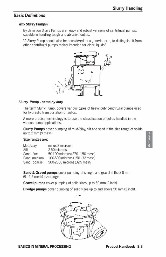
Product Handbook 8:3
Slurry Handling
Slur
ry h
andl
ing
BASICS IN MINERAL PROCESSING
Basic Definitions
Why Slurry Pumps?
By definition Slurry Pumps are heavy and robust versions of centrifugal pumps,capable in handling tough and abrasive duties.
”A Slurry Pump should also be considered as a generic term, to distinguish it fromother centrifugal pumps mainly intended for clear liquids”.
Slurry Pump - name by duty
The term Slurry Pump, covers various types of heavy duty centrifugal pumps usedfor hydraulic transportation of solids.
A more precise terminology is to use the classification of solids handled in thevarious pump applications.
Slurry Pumps cover pumping of mud/clay, silt and sand in the size range of solidsup to 2 mm (9 mesh)
Size ranges are:
Mud/clay minus 2 micronsSilt 2-50 micronsSand, fine 50-100 microns (270 - 150 mesh)Sand, medium 100-500 microns (150 - 32 mesh)Sand, coarse 500-2000 microns (32-9 mesh)
Sand & Gravel pumps cover pumping of shingle and gravel in the 2-8 mm(9 - 2,5 mesh) size range
Gravel pumps cover pumping of solid sizes up to 50 mm (2 inch).
Dredge pumps cover pumping of solid sizes up to and above 50 mm (2 inch).
8:4 Product Handbook
Slurry HandlingSl
urry
Han
dlin
g
BASICS IN MINERAL PROCESSING
Slurry Pump - name by application
Process applications also provide the terminology, typically
Froth pumps define by application the handling of frothy slurries, mainly inflotation.
Carbon transfer pumps define the gentle hydraulic transportation of carbon inCIP (carbon in pulp) and CIL (carbon in leach) circuits.
Sump pumps, also an established name typically operating pumps from floorsumps, submerged pump houses, but having dry bearings and drives.
Submersible Pumps The entire unit, including drive, is submersed.
All Slurry Pumps are in practice named after the given application:
• Slurry Pumps • Gravel pumps • Dredge pumps • Sump pumps • Froth pumps
• Carbon Transfer pumps • Submersible pumps
There are principally three different designs:
• Horizontal and vertical tank (dry installation) • Vertical sump (semi dry installation)
• Tank (dry installation) • Submersible (wet installation)
Slurry Pump designs are selected and supplied according to the wear conditions
• Highly abrasive • Abrasive • Mildly abrasive
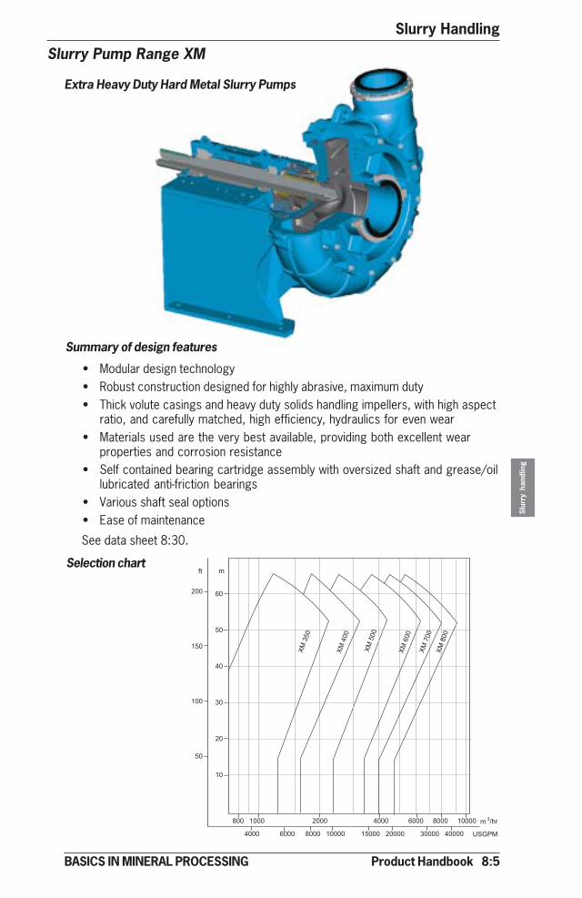
Product Handbook 8:5
Slurry Handling
Slur
ry h
andl
ing
BASICS IN MINERAL PROCESSING
Slurry Pump Range XM
Extra Heavy Duty Hard Metal Slurry Pumps
Selection chart
Summary of design features
• Modular design technology• Robust construction designed for highly abrasive, maximum duty• Thick volute casings and heavy duty solids handling impellers, with high aspect
ratio, and carefully matched, high efficiency, hydraulics for even wear• Materials used are the very best available, providing both excellent wear
properties and corrosion resistance• Self contained bearing cartridge assembly with oversized shaft and grease/oil
lubricated anti-friction bearings• Various shaft seal options• Ease of maintenance
See data sheet 8:30.
��
��
��
��
��
��
���
���
���
��
������� ���� ���� �������������
���� ���� ��������� ���������� ����������
� �
� ��
�����
�
�����
�����
�����
�����
�����
�����
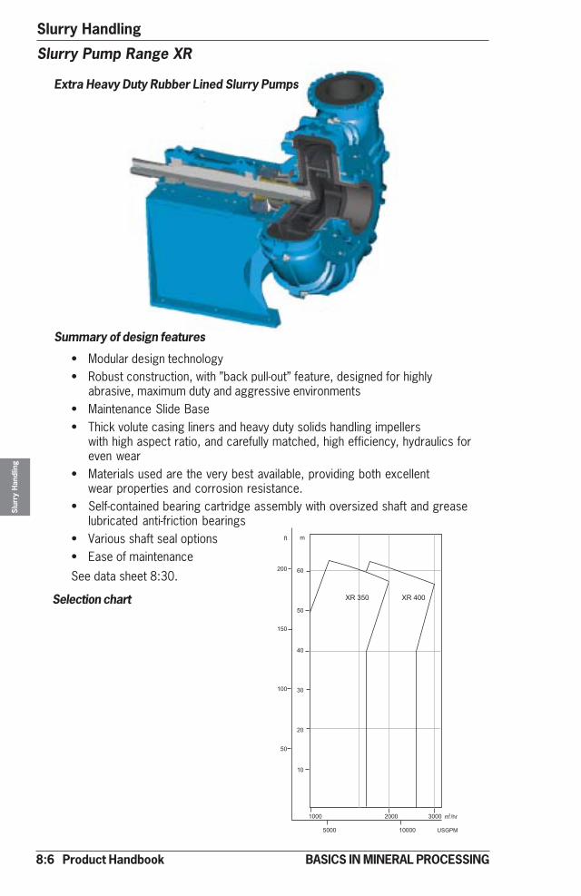
8:6 Product Handbook
Slurry HandlingSl
urry
Han
dlin
g
BASICS IN MINERAL PROCESSING
Selection chart
Summary of design features
• Modular design technology• Robust construction, with ”back pull-out” feature, designed for highly
abrasive, maximum duty and aggressive environments• Maintenance Slide Base• Thick volute casing liners and heavy duty solids handling impellers
with high aspect ratio, and carefully matched, high efficiency, hydraulics foreven wear
• Materials used are the very best available, providing both excellentwear properties and corrosion resistance.
• Self-contained bearing cartridge assembly with oversized shaft and greaselubricated anti-friction bearings
• Various shaft seal options• Ease of maintenance
Slurry Pump Range XR
Extra Heavy Duty Rubber Lined Slurry Pumps
See data sheet 8:30.��
��
��
��
��
��
���
���
���
��
�
���� ���� ����
���� �����
�
� ��
�����
�
����� �����
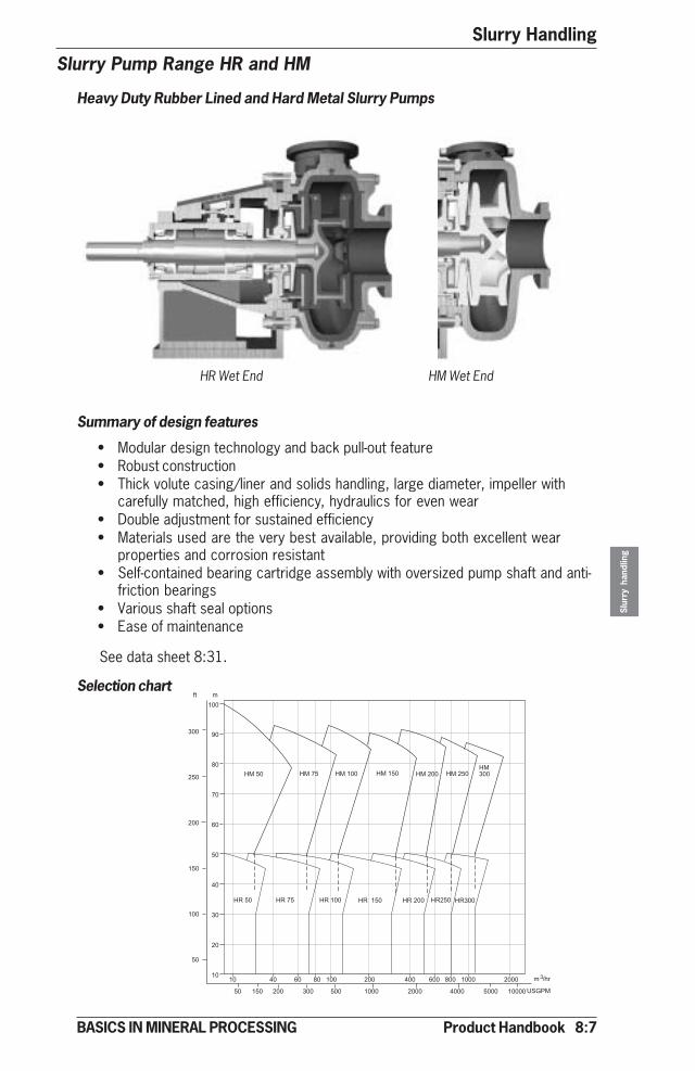
Product Handbook 8:7
Slurry Handling
Slur
ry h
andl
ing
BASICS IN MINERAL PROCESSING
�� �� �� ����� ��� ��� ��������������
���
��
��
��
��
��
��
��
��
��
���� ���� ����� ���������������
���� ���� ����� ����� ����� ����������
���
���
���
���
���
��
� �
� ��
���������� ��� ��� ��� ���� ���� ���� ���� �����
�
�����
Slurry Pump Range HR and HM
Heavy Duty Rubber Lined and Hard Metal Slurry Pumps
HR Wet End HM Wet End
Selection chart
Summary of design features
• Modular design technology and back pull-out feature• Robust construction• Thick volute casing/liner and solids handling, large diameter, impeller with
carefully matched, high efficiency, hydraulics for even wear• Double adjustment for sustained efficiency• Materials used are the very best available, providing both excellent wear
properties and corrosion resistant• Self-contained bearing cartridge assembly with oversized pump shaft and anti-
friction bearings• Various shaft seal options• Ease of maintenance
See data sheet 8:31.

8:8 Product Handbook
Slurry HandlingSl
urry
Han
dlin
g
BASICS IN MINERAL PROCESSING
��
��
��
��
���
���
���
���
���
���
��
��
��
� �� �� �� ������ ��� ��� ��������� ���� ���� ����
�� �� ������������ ��������������������������������������
��
��
��
��
���� ���� ����� ����� ����� �����
�����
�����
���� ����� �����
�����
� �
�����
���� ����
���� ����� ����� �����
�
�����
Slurry Pump Range MR and MM
Mining Duty Rubber Lined and Hard Metal Slurry Pumps
MR Wet End MM Wet End
Summary of design features
• Modular design technology and back pull-out feature• Robust construction• Solids handling, medium diameter, impeller with carefully matched, high efficiency,
hydraulics for even wear• Double adjustment for sustained efficiency• Materials used are the very best available, providing both excellent wear properties
and corrosion resistant• Self contained bearing cartridge assembly with oversized pump shaft and grease
lubricated taper roller bearings• Various shaft seal options• Ease of maintenance
Selection chart
See data sheet 8:32.

Product Handbook 8:9
Slurry Handling
Slur
ry h
andl
ing
BASICS IN MINERAL PROCESSING
Slurry Pump Range VS
Vertical Sump Pumps
Summary of design features
• Simple installation• Cantilever design without submerged bearings or shaft seal• Bearing assembly with double protection sealing arrangement to prevent ingress of
slurry• Materials used are the very best available, providing both excellent wear properties
and corrosion resistance• Wear parts are available in a variety of different materials with full interchangeability• Range of impeller options
Selection chart
See data sheet 8:33.
� �� �� �� ������ ��� ������������ ���� ����� ��
�� �� ��� ��� ��� ��� ��� ��� ��������������� ���� ���� ���� ���������
�
��
��
��
��
���
���
���
��
��
��
�
����������
����������
����������
����������
����������
���������� �
����������
���������� �
����������
���������� �
���������
���������
���������
���������
���������
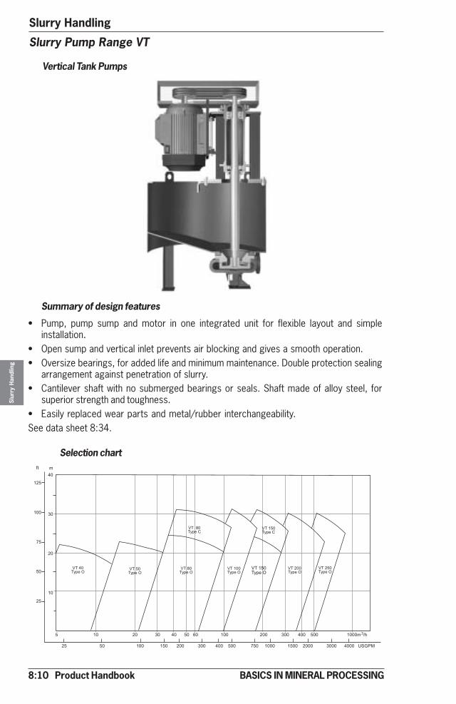
8:10 Product Handbook
Slurry HandlingSl
urry
Han
dlin
g
BASICS IN MINERAL PROCESSING
Slurry Pump Range VT
Vertical Tank Pumps
� �� �� �� ������ ��� ������������ ����� ��
�� �� ��� ��� ��� ��� ��� ��� ��������������� ���� ���� �����
��
��
��
��
���
���
��
��
��
�
������!"#$
������!"#$
������!"#�
������!"#$
�����!"#$
�����!"#$
�����!"#$
�
�����!"#�
������!"#$
Selection chart
Summary of design features
• Pump, pump sump and motor in one integrated unit for flexible layout and simpleinstallation.
• Open sump and vertical inlet prevents air blocking and gives a smooth operation.• Oversize bearings, for added life and minimum maintenance. Double protection sealing
arrangement against penetration of slurry.• Cantilever shaft with no submerged bearings or seals. Shaft made of alloy steel, for
superior strength and toughness.• Easily replaced wear parts and metal/rubber interchangeability.See data sheet 8:34.
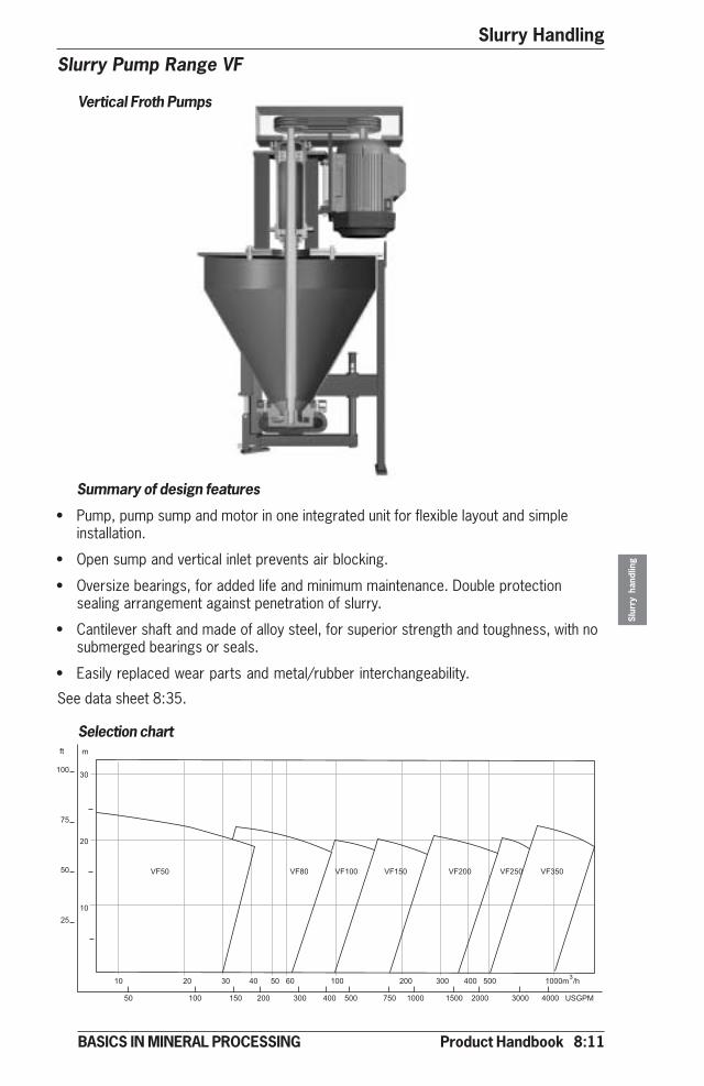
Product Handbook 8:11
Slurry Handling
Slur
ry h
andl
ing
BASICS IN MINERAL PROCESSING
Slurry Pump Range VF
Vertical Froth Pumps
Summary of design features
• Pump, pump sump and motor in one integrated unit for flexible layout and simpleinstallation.
• Open sump and vertical inlet prevents air blocking.
• Oversize bearings, for added life and minimum maintenance. Double protectionsealing arrangement against penetration of slurry.
• Cantilever shaft and made of alloy steel, for superior strength and toughness, with nosubmerged bearings or seals.
• Easily replaced wear parts and metal/rubber interchangeability.
�� �� �� ������ ��� ������������ ����� ��
�� ��� ��� ��� ��� ��� ��� ��������������� ���� ���� �����
��
��
��
���
��
��
��
� �
�%�� �%�� �%��� �%��� �%��� �%��� �%���
Selection chart
See data sheet 8:35.
8:12 Product Handbook
Slurry HandlingSl
urry
Han
dlin
g
BASICS IN MINERAL PROCESSING
Application Guide for Slurry PumpsAs mentioned before, the only limitation for hydraulic transportation is your ownimagination.
This application guide is a simple way to find out what type of pump to be used fordifferent slurry operations.
Selection by Solids page 8:13
Selection by Head and Volume page 8:13
Selection by Slurry type page 8:14
Selection by industrial segment
Metallic and Industrial minerals page 8:15
Construction page 8:16
Coal page 8:17
Waste & Recycling page 8:17
Power & FGD page 8:17
Pulp & Paper page 8:18
Metallurgy page 8:18
Chemical page 8:19
Mining page 8:19
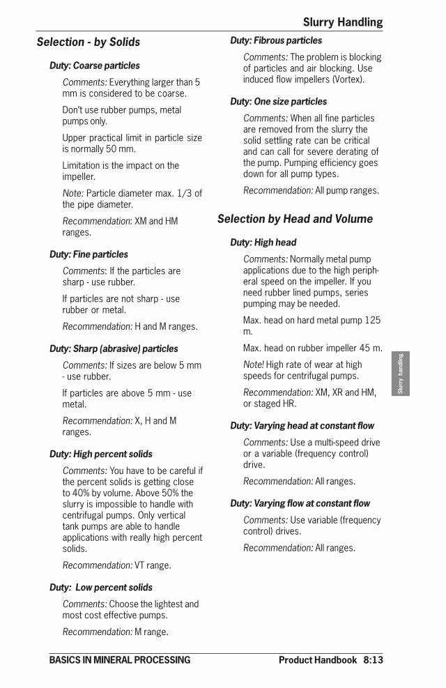
Product Handbook 8:13
Slurry Handling
Slur
ry h
andl
ing
BASICS IN MINERAL PROCESSING
Selection - by Solids
Duty: Coarse particles
Comments: Everything larger than 5mm is considered to be coarse.
Don’t use rubber pumps, metalpumps only.
Upper practical limit in particle sizeis normally 50 mm.
Limitation is the impact on theimpeller.
Note: Particle diameter max. 1/3 ofthe pipe diameter.
Recommendation: XM and HMranges.
Duty: Fine particles
Comments: If the particles aresharp - use rubber.
If particles are not sharp - userubber or metal.
Recommendation: H and M ranges.
Duty: Sharp (abrasive) particles
Comments: If sizes are below 5 mm- use rubber.
If particles are above 5 mm - usemetal.
Recommendation: X, H and Mranges.
Duty: High percent solids
Comments: You have to be careful ifthe percent solids is getting closeto 40% by volume. Above 50% theslurry is impossible to handle withcentrifugal pumps. Only verticaltank pumps are able to handleapplications with really high percentsolids.
Recommendation: VT range.
Duty: Low percent solids
Comments: Choose the lightest andmost cost effective pumps.
Recommendation: M range.
Duty: Fibrous particles
Comments: The problem is blockingof particles and air blocking. Useinduced flow impellers (Vortex).
Duty: One size particles
Comments: When all fine particlesare removed from the slurry thesolid settling rate can be criticaland can call for severe derating ofthe pump. Pumping efficiency goesdown for all pump types.
Recommendation: All pump ranges.
Selection by Head and Volume
Duty: High head
Comments: Normally metal pumpapplications due to the high periph-eral speed on the impeller. If youneed rubber lined pumps, seriespumping may be needed.
Max. head on hard metal pump 125m.
Max. head on rubber impeller 45 m.
Note! High rate of wear at highspeeds for centrifugal pumps.
Recommendation: XM, XR and HM,or staged HR.
Duty: Varying head at constant flow
Comments: Use a multi-speed driveor a variable (frequency control)drive.
Recommendation: All ranges.
Duty: Varying flow at constant flow
Comments: Use variable (frequencycontrol) drives.
Recommendation: All ranges.

8:14 Product Handbook
Slurry HandlingSl
urry
Han
dlin
g
BASICS IN MINERAL PROCESSING
Duty: High suction lift
Comments: Metal pumps arepreferred due to risk of rubberlining collapse on high suction lifts.
Max. practical suction lift 5 - 8 mdepending on S.G.
Pumps are not self-priming, i.e. youneed a priming device.
The pump and inlet pipe need to befilled with liquid before starting.
Recommendation: XM, HM and MM.
Duty: High flow
Comments: Use parallel pumpinstallations, see page 11-92.
Risk for cavitation, see section 10.
Recommendation: All ranges.
Duty: Low flow
Comments: Compare to BEP*, seesection 12.
At low flows rubber linings can beoverheated. Use metal.
Be careful if heads are high andflow is low.
Open vertical pumps have noproblems.
*BEP = Best Efficiency Point
Recommendation: Try to use VS, VTand VF ranges.
Duty: Fluctuating flow
Comments: Use horizontal pumpswith variable speed drive or fixedspeed vertical pumps.
Recommendation: VT, VF or VS.Horizontals; all types with variablespeed drives.
Selection by Slurry Type
Duty: Fragile slurries
Comments: Use induced flowimpellers (fully recessed).
Both metal and rubber pumps canbe used. Both horizontal andvertical pumps can be used.
Recommendation: All ranges.
Duty: Hydrocarbon slurries (oil andreagents contaminated)
Comments: Natural rubber is out.
Be careful with seal material ofnatural rubber. Use synthetic seals.
Use metallic pumps or wear partsin polyurethane.
Recommendation: All ranges.
Duty: High temperature (greater than100o C) slurries
Comments: (Temperature limit fornatural rubber is 60o C.) Seesection 9 for synthetic rubbers.
Practical limit for operating tem-perature is 135o C. Above thistemperature the bearings can beover-heated!
Recommendation: All horizontalranges.
Duty: Frothy slurries
Comments: Use a froth pump ofvertical design.
Recommendation: VF range.
Duty: Hazardous slurries
Comments: Warning! This case hasto be referred back to the pumpsales support departments.
Shaft sealing is critical fromexplosion point of view. Normallyclosed pump systems are used.
Recommendation: Horizontalranges.
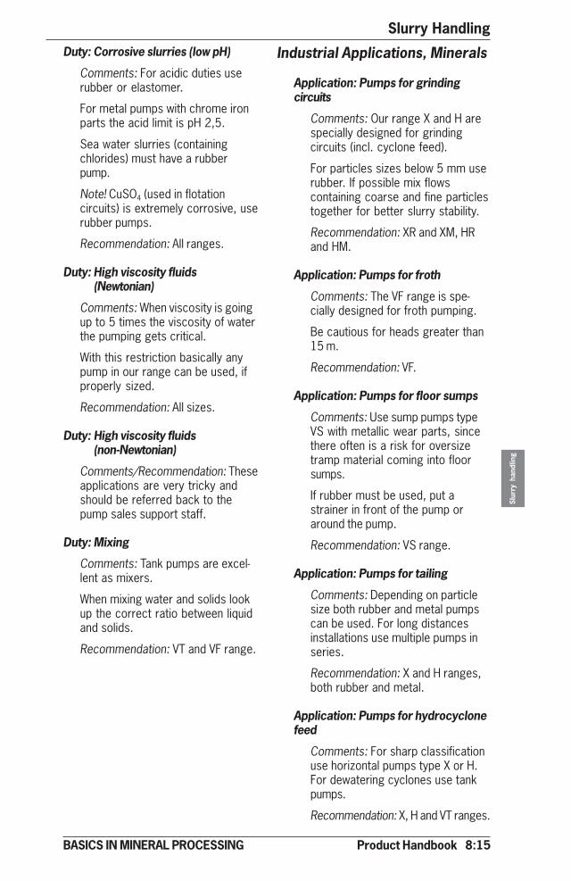
Product Handbook 8:15
Slurry Handling
Slur
ry h
andl
ing
BASICS IN MINERAL PROCESSING
Duty: Corrosive slurries (low pH)
Comments: For acidic duties userubber or elastomer.
For metal pumps with chrome ironparts the acid limit is pH 2,5.
Sea water slurries (containingchlorides) must have a rubberpump.
Note! CuSO4 (used in flotationcircuits) is extremely corrosive, userubber pumps.
Recommendation: All ranges.
Duty: High viscosity fluids(Newtonian)
Comments: When viscosity is goingup to 5 times the viscosity of waterthe pumping gets critical.
With this restriction basically anypump in our range can be used, ifproperly sized.
Recommendation: All sizes.
Duty: High viscosity fluids(non-Newtonian)
Comments/Recommendation: Theseapplications are very tricky andshould be referred back to thepump sales support staff.
Duty: Mixing
Comments: Tank pumps are excel-lent as mixers.
When mixing water and solids lookup the correct ratio between liquidand solids.
Recommendation: VT and VF range.
Industrial Applications, Minerals
Application: Pumps for grindingcircuits
Comments: Our range X and H arespecially designed for grindingcircuits (incl. cyclone feed).
For particles sizes below 5 mm userubber. If possible mix flowscontaining coarse and fine particlestogether for better slurry stability.
Recommendation: XR and XM, HRand HM.
Application: Pumps for froth
Comments: The VF range is spe-cially designed for froth pumping.
Be cautious for heads greater than15 m.
Recommendation: VF.
Application: Pumps for floor sumps
Comments: Use sump pumps typeVS with metallic wear parts, sincethere often is a risk for oversizetramp material coming into floorsumps.
If rubber must be used, put astrainer in front of the pump oraround the pump.
Recommendation: VS range.
Application: Pumps for tailing
Comments: Depending on particlesize both rubber and metal pumpscan be used. For long distancesinstallations use multiple pumps inseries.
Recommendation: X and H ranges,both rubber and metal.
Application: Pumps for hydrocyclonefeed
Comments: For sharp classificationuse horizontal pumps type X or H.For dewatering cyclones use tankpumps.
Recommendation: X, H and VT ranges.
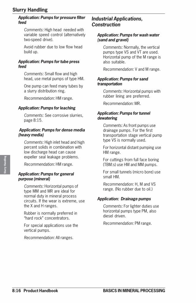
8:16 Product Handbook
Slurry HandlingSl
urry
Han
dlin
g
BASICS IN MINERAL PROCESSING
Application: Pumps for pressure filterfeed
Comments: High head needed withvariable speed control (alternativelytwo-speed drive).
Avoid rubber due to low flow headbuild up.
Application: Pumps for tube pressfeed
Comments: Small flow and highhead, use metal pumps of type HM.
One pump can feed many tubes bya slurry distribution ring.
Recommendation: HM range.
Application: Pumps for leaching
Comments: See corrosive slurries,page 8:15.
Application: Pumps for dense media(heavy media)
Comments: High inlet head and highpercent solids in combination withlow discharge head can causeexpeller seal leakage problems.
Recommendation: HM range.
Application: Pumps for generalpurpose (mineral)
Comments: Horizontal pumps oftype MM and MR are ideal fornormal duty in mineral processcircuits. If the wear is extreme, usethe X and H ranges.
Rubber is normally preferred in“hard rock” concentrators.
For special applications use thevertical pumps.
Recommendation: All ranges.
Industrial Applications,Construction
Application: Pumps for wash water(sand and gravel)
Comments: Normally, the verticalpumps type VS and VT are used.Horizontal pump of the M range isalso suitable.
Recommendation: V and M range.
Application: Pumps for sandtransportation
Comments: Horizontal pumps withrubber lining are preferred.
Recommendation: MR.
Application: Pumps for tunneldewatering
Comments: As front pumps usedrainage pumps. For the firsttransportation stage vertical pumptype VS is normally used.
For horizontal distant pumping useHM range.
For cuttings from full face boring(TBM:s) use HM and MM pumps.
For small tunnels (micro bore) usesmall HM.
Recommendation: H, M and VSrange. (No rubber due to oil.)
Application: Drainage pumps
Comments: For lighter duties usehorizontal pumps type PM, alsodiesel driven.
Recommendation: PM range.
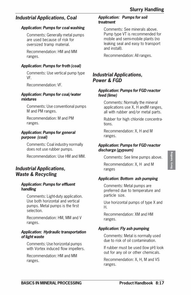
Product Handbook 8:17
Slurry Handling
Slur
ry h
andl
ing
BASICS IN MINERAL PROCESSING
Industrial Applications, Coal
Application: Pumps for coal washing
Comments: Generally metal pumpsare used because of risk foroversized tramp material.
Recommendation: HM and MMranges.
Application: Pumps for froth (coal)
Comments: Use vertical pump typeVF.
Recommendation: VF.
Application: Pumps for coal/watermixtures
Comments: Use conventional pumpsM and PM ranges.
Recommendation: M and PMranges.
Application: Pumps for generalpurpose (coal)
Comments: Coal industry normallydoes not use rubber pumps.
Recommendation: Use HM and MM.
Industrial Applications,Waste & Recycling
Application: Pumps for effluenthandling
Comments: Light-duty application.Use both horizontal and verticalpumps. Metal pumps is the firstselection.
Recommendation: HM, MM and Vranges.
Application: Hydraulic transportationof light waste
Comments: Use horizontal pumpswith Vortex induced flow impellers.
Recommendation: HM and MMranges.
Application: Pumps for soiltreatment
Comments: See minerals above.Pump type VT is recommended formobile and semi-mobile plants (noleaking seal and easy to transportand install).
Recommendation: All ranges.
Industrial Applications,Power & FGD
Application: Pumps for FGD reactorfeed (lime)
Comments: Normally the mineralapplications use X, H andM ranges,all with rubber and/or metal parts.
Rubber for high chloride concentra-tions.
Recommendation: X, H and Mranges.
Application: Pumps for FGD reactordischarge (gypsum)
Comments: See lime pumps above.
Recommendation: X, H and Mranges
Application: Bottom ash pumping
Comments: Metal pumps arepreferred due to temperature andparticle size.
Use horizontal pumps of type X andH.
Recommendation: XM and HMranges.
Application: Fly ash pumping
Comments: Metal is normally useddue to risk of oil contamination.
If rubber must be used (low pH) lookout for any oil or other chemicals.
Recommendation: X, H, M and VSranges.
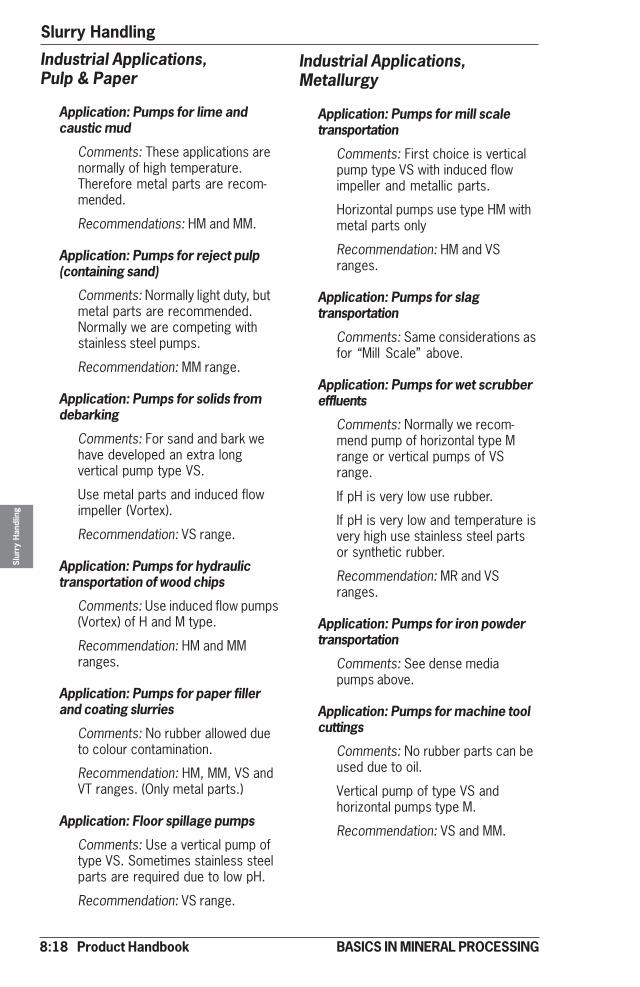
8:18 Product Handbook
Slurry HandlingSl
urry
Han
dlin
g
BASICS IN MINERAL PROCESSING
Industrial Applications,Pulp & Paper
Application: Pumps for lime andcaustic mud
Comments: These applications arenormally of high temperature.Therefore metal parts are recom-mended.
Recommendations: HM and MM.
Application: Pumps for reject pulp(containing sand)
Comments: Normally light duty, butmetal parts are recommended.Normally we are competing withstainless steel pumps.
Recommendation: MM range.
Application: Pumps for solids fromdebarking
Comments: For sand and bark wehave developed an extra longvertical pump type VS.
Use metal parts and induced flowimpeller (Vortex).
Recommendation: VS range.
Application: Pumps for hydraulictransportation of wood chips
Comments: Use induced flow pumps(Vortex) of H and M type.
Recommendation: HM and MMranges.
Application: Pumps for paper fillerand coating slurries
Comments: No rubber allowed dueto colour contamination.
Recommendation: HM, MM, VS andVT ranges. (Only metal parts.)
Application: Floor spillage pumps
Comments: Use a vertical pump oftype VS. Sometimes stainless steelparts are required due to low pH.
Recommendation: VS range.
Industrial Applications,Metallurgy
Application: Pumps for mill scaletransportation
Comments: First choice is verticalpump type VS with induced flowimpeller and metallic parts.
Horizontal pumps use type HM withmetal parts only
Recommendation: HM and VSranges.
Application: Pumps for slagtransportation
Comments: Same considerations asfor “Mill Scale” above.
Application: Pumps for wet scrubbereffluents
Comments: Normally we recom-mend pump of horizontal type Mrange or vertical pumps of VSrange.
If pH is very low use rubber.
If pH is very low and temperature isvery high use stainless steel partsor synthetic rubber.
Recommendation: MR and VSranges.
Application: Pumps for iron powdertransportation
Comments: See dense mediapumps above.
Application: Pumps for machine toolcuttings
Comments: No rubber parts can beused due to oil.
Vertical pump of type VS andhorizontal pumps type M.
Recommendation: VS and MM.
Product Handbook 8:19
Slurry Handling
Slur
ry h
andl
ing
BASICS IN MINERAL PROCESSING
Industrial Applications,Chemical
Application: Pumps for acid slurries
Comments: First recommendation ishorizontal pumps with rubber orstainless parts. For extremelyabrasive slurries use horizontalpump type HR.
Recommendation: MR and HRranges.
Application: Pumps for brines
Comments: Very corrosive applica-tions. Can also be abrasive (crys-tals).
Polyurethane can be used to avoidcrystallization on pump parts.
Recommendation: HM, HR, MM, MRand VS (polyurethane parts).
Application: Pumps for caustics
Comments: Both rubber and metalpumps can be used. Easy applica-tion.
Recommendation: MM, MR, PM andVS ranges.
Industrial Applications, Mining
Application: Pumps for hydraulicback filling (with or without cement)
Comments: Watch out for deslimedtailings! Use horizontal pumps oftype H or M with rubber or metalparts.
Recommendation: H and M ranges.
Application: Pumps for mine water(with solids)
Comments: Normal recommenda-tion is horizontal pumps type HM(multi stage if required).
Watch out for corrosion!
Recommendation: HM.
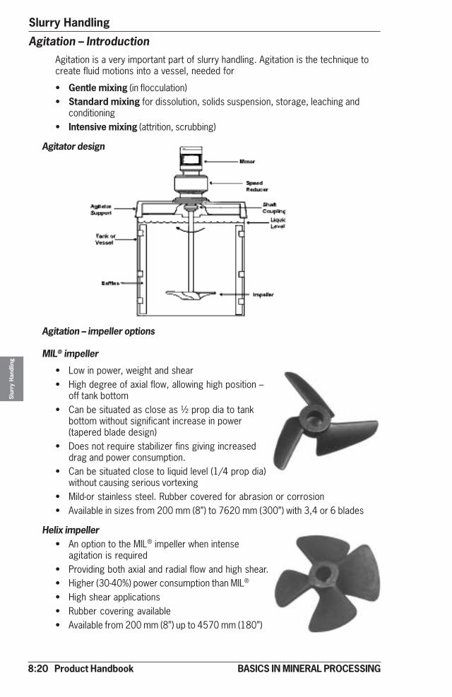
8:20 Product Handbook
Slurry HandlingSl
urry
Han
dlin
g
BASICS IN MINERAL PROCESSING
Agitation – IntroductionAgitation is a very important part of slurry handling. Agitation is the technique tocreate fluid motions into a vessel, needed for
• Gentle mixing (in flocculation)• Standard mixing for dissolution, solids suspension, storage, leaching and
conditioning• Intensive mixing (attrition, scrubbing)
Agitator design
Agitation – impeller options
MIL® impeller
• Low in power, weight and shear• High degree of axial flow, allowing high position –
off tank bottom• Can be situated as close as ½ prop dia to tank
bottom without significant increase in power(tapered blade design)
• Does not require stabilizer fins giving increaseddrag and power consumption.
• Can be situated close to liquid level (1/4 prop dia)without causing serious vortexing
• Mild-or stainless steel. Rubber covered for abrasion or corrosion• Available in sizes from 200 mm (8”) to 7620 mm (300”) with 3,4 or 6 blades
Helix impeller• An option to the MIL® impeller when intense
agitation is required• Providing both axial and radial flow and high shear.• Higher (30-40%) power consumption than MIL®
• High shear applications• Rubber covering available• Available from 200 mm (8”) up to 4570 mm (180”)
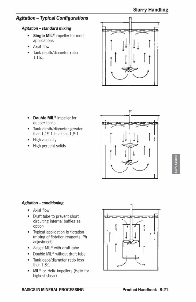
Product Handbook 8:21
Slurry Handling
Slur
ry h
andl
ing
BASICS IN MINERAL PROCESSING
Agitation – Typical Configurations
Agitation – standard mixing
• Single MIL® impeller for mostapplications
• Axial flow• Tank depth/diameter ratio
1,15:1
• Double MIL® impeller fordeeper tanks
• Tank depth/diameter greaterthan 1,15:1 less than 1,8:1
• High viscosity• High percent solids
Agitation – conditioning
• Axial flow• Draft tube to prevent short
circuiting internal baffles asoption
• Typical application is flotation(mixing of flotation reagents, Phadjustment)
• Single MIL® with draft tube• Double MIL® without draft tube• Tank dept/diameter ratio less
than 1.8:1• MIL® or Helix impellers (Helix for
highest shear)
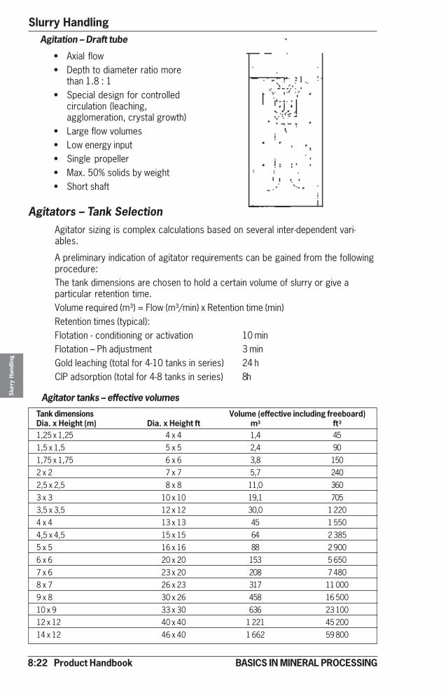
8:22 Product Handbook
Slurry HandlingSl
urry
Han
dlin
g
BASICS IN MINERAL PROCESSING
Agitation – Draft tube
• Axial flow• Depth to diameter ratio more
than 1.8 : 1• Special design for controlled
circulation (leaching,agglomeration, crystal growth)
• Large flow volumes• Low energy input• Single propeller• Max. 50% solids by weight• Short shaft
Agitators – Tank SelectionAgitator sizing is complex calculations based on several inter-dependent vari-ables.
A preliminary indication of agitator requirements can be gained from the followingprocedure:The tank dimensions are chosen to hold a certain volume of slurry or give aparticular retention time.Volume required (m³) = Flow (m³/min) x Retention time (min)Retention times (typical):Flotation - conditioning or activation 10 minFlotation – Ph adjustment 3 minGold leaching (total for 4-10 tanks in series) 24 hCIP adsorption (total for 4-8 tanks in series) 8h
Agitator tanks – effective volumes
Tank dimensions Volume (effective including freeboard)Dia. x Height (m) Dia. x Height ft m3 ft3
1,25 x 1,25 4 x 4 1,4 451,5 x 1,5 5 x 5 2,4 901,75 x 1,75 6 x 6 3,8 1502 x 2 7 x 7 5,7 2402,5 x 2,5 8 x 8 11,0 3603 x 3 10 x 10 19,1 7053,5 x 3,5 12 x 12 30,0 1 2204 x 4 13 x 13 45 1 5504,5 x 4,5 15 x 15 64 2 3855 x 5 16 x 16 88 2 9006 x 6 20 x 20 153 5 6507 x 6 23 x 20 208 7 4808 x 7 26 x 23 317 11 0009 x 8 30 x 26 458 16 50010 x 9 33 x 30 636 23 10012 x 12 40 x 40 1 221 45 20014 x 12 46 x 40 1 662 59 800

Product Handbook 8:23
Slurry Handling
Slur
ry h
andl
ing
BASICS IN MINERAL PROCESSING
Agitation – Impeller Section , MIL®
Once the tank size has been established an estimation of the mechanism requiredfor a “Standard” agitator or “Conditioner” can be made by defining the duty as“Light”, “Medium” or “Heavy” as follows:
Standard Agitators - Duty
Duty Light Medium HeavySlurry viscosity (cP) 300 500 1000Maximum solids size (mm) (mesh) 0,1 (150) 0,2 (65) 0,35 (42)Maximum dry solids s.g. (g/cm3) 3,0 3,5 3,5Maximum liquid s.g. (g/cm3) 1,0 1,1 1,2Maximum solids content (% by weight) 15 25 45
Conditioners - Duty
Duty Medium HeavyMaximum solids size (mm) (mesh) 0,25 (60) 0,25 (60)Maximum solids s.g. (g/cm3) 2.7 3,5Maximum liquid s.g. (g/cm3) 1.0 1,0Maximum solids content (% by weight) 20 45
Standard Agitators (single MIL® impeller), Metric std
Light Duty Medium Duty Heavy DutyTank dim. Prop. Prop. Motor Prop. Prop. Motor Prop. Prop. MotorDia x Height Vol dia blade power dia blade power dia blade power[m] m3 mm No. kW* mm No. kW* mm No. kW*
1,25 x 1,25 1,4 305 3 0,18 380 3 0,37 610 3 1,11,5 x 1,5 2,4 380 3 0,25 455 3 0,55 610 3 1,11,75 x 1,75 3,8 455 3 0,37 610 3 1,1 760 3 2,22 x 2 5,7 610 3 0,75 610 3 1,1 915 6 32,5 x 2,5 11,0 610 3 0,75 760 3 1,5 1 065 6 43 x 3 19,1 760 3 1,1 915 6 2,2 1 220 6 5,53,5 x 3,5 30 915 6 2,2 1 065 6 3 1 370 6 5,54 x 4 45 1 065 6 3 1 220 6 4 1 525 6 7,54,5 x 4,5 64 1 220 6 3 1 370 6 5,5 1 830 6 115 x 5 88 1 370 6 4 1 525 6 5,5 2 135 6 156 x 6 152 1 525 6 5,5 1 830 6 7,5 2 440 6 18,57 x 6 208 1 830 6 7,5 2 135 6 11 2 745 6 228 x 7 317 2 135 6 11 2 440 6 15 3 050 6 309 x 8 458 2 440 6 11 2 745 6 18,5 3 660 6 4510 x 9 636 2 745 6 15 3 050 6 22 4 570 6 7512 x 12 1 226 3 050 6 18,5 3 660 6 30 4 570 6 7514 x 12 1 662 3 660 6 30 4 570 6 55* kW as connected motor power
8:24 Product Handbook
Slurry HandlingSl
urry
Han
dlin
g
BASICS IN MINERAL PROCESSING
Standard Agitators (single MIL® impeller), US std
Conditioners (single MIL® impeller), Metric std
Light Duty Medium Duty Heavy DutyTank dim. Prop. Prop Motor Prop. Prop. Motor Prop. Prop. MotorDia x Height Vol dia blade power dia blade power dia blade powerft ft3 inch No. hp* inch No. hp* inch No. hp*4 x 4 45 12 3 0,25 15 3 0,50 24 3 1,55 x 5 90 15 3 0.34 18 3 0,75 14 3 1,56 x 6 150 18 3 0,50 24 3 1,5 30 3 3,07 x 7 240 24 3 1,0 24 3 1,5 36 6 4,08 x 8 360 24 3 1,0 30 3 2,0 42 6 5,410 x 10 705 30 3 1,5 36 6 3,0 48 6 7,512 x 12 1 220 36 6 3,0 42 6 4,0 54 6 7,513 x 13 1 550 42 6 4,0 48 6 5,4 60 6 10,215 x 15 2 385 48 6 4,0 54 6 7,5 72 6 15,016 x 16 2 900 54 6 5,4 60 6 7,5 8420 x 20 5 650 60 6 7,5 72 6 10,2 96 6 20,023 x 20 7 480 72 6 10,2 84 6 15,0 108 6 30,026 x 23 11 000 84 6 15,0 96 6 20,0 120 6 40,030 x 26 16 500 96 6 15,0 108 6 25,0 144 6 6133 x 30 23 100 108 6 20,0 120 6 30,0 180 6 10240 x 40 45 200 120 6 25,0 144 6 40,0 180 6 10246 x 40 59 800 144 6 40,0 180 6 75,0 - - -
* hp as connected motor power
Medium Duty Heavy DutyTank dim. Prop. Prop. Motor Prop. Prop. MotorDia x height Volume dia blades power dia blades powerm m3 mm No. kW* mm No. kW*1,25x1,25 1,4 380 3 0,37 455 3 0,751,5x1,5 2,4 455 3 0,55 610 3 1,51,75x1,75 3,8 610 3 1,1 610 3 1,52x2 5,7 610 3 1,1 760 3 2,22,5x2,5 11,0 760 3 1,5 915 6 33x3 19,1 915 6 2,2 1065 6 43,5x3,5 30 1065 6 3 1220 6 5,54x4 45 1220 6 4 1370 6 7,54,5x4,5 64 1370 6 5,5 1525 6 115x5 88 1525 6 7,5 1830 6 116x6 152 1830 6 11 2135 6 157x6 208 2135 6 11 2440 6 228x7 317 2440 6 15 2745 6 30* kW power as connected motor power
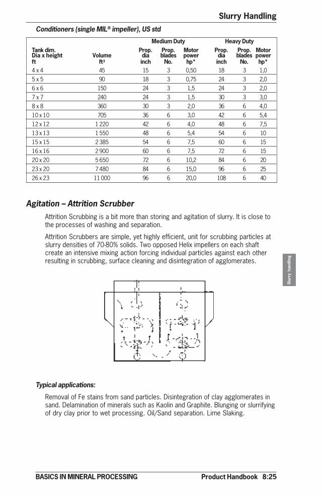
Product Handbook 8:25
Slurry Handling
Slur
ry h
andl
ing
BASICS IN MINERAL PROCESSING
Conditioners (single MIL® impeller), US std
Medium Duty Heavy DutyTank dim. Prop. Prop. Motor Prop. Prop. MotorDia x height Volume dia blades power dia blades powerft ft3 inch No. hp* inch No. hp*4 x 4 45 15 3 0,50 18 3 1,05 x 5 90 18 3 0,75 24 3 2,06 x 6 150 24 3 1,5 24 3 2,07 x 7 240 24 3 1,5 30 3 3,08 x 8 360 30 3 2,0 36 6 4,010 x 10 705 36 6 3,0 42 6 5,412 x 12 1 220 42 6 4,0 48 6 7,513 x 13 1 550 48 6 5,4 54 6 1015 x 15 2 385 54 6 7,5 60 6 1516 x 16 2 900 60 6 7,5 72 6 1520 x 20 5 650 72 6 10,2 84 6 2023 x 20 7 480 84 6 15,0 96 6 2526 x 23 11 000 96 6 20,0 108 6 40
Agitation – Attrition ScrubberAttrition Scrubbing is a bit more than storing and agitation of slurry. It is close tothe processes of washing and separation.
Attrition Scrubbers are simple, yet highly efficient, unit for scrubbing particles atslurry densities of 70-80% solids. Two opposed Helix impellers on each shaftcreate an intensive mixing action forcing individual particles against each otherresulting in scrubbing, surface cleaning and disintegration of agglomerates.
Typical applications:
Removal of Fe stains from sand particles. Disintegration of clay agglomerates insand. Delamination of minerals such as Kaolin and Graphite. Blunging or slurrifyingof dry clay prior to wet processing. Oil/Sand separation. Lime Slaking.
8:26 Product Handbook
Slurry HandlingSl
urry
Han
dlin
g
BASICS IN MINERAL PROCESSING
Attrition Scrubber – SizingRestriction: Maximum size of individual particle to scrubber is 10 mm.
Due to the flow pattern an even number of cells must be selected (e.g. 2,4,6cells). Base the retention time on test results or on an existing installation. In theabsence of any other information assume a retention time of 6-8 minutes at 75%solids w/w for a typical sand scrubbing duty.
Max. flow/double cell
Scrubber size m³/h USGPM
24x24 13 5632x32 22 9940x40 32 14148x48 64 28256x56 96 42464x64 112 49372x72 128 564
Attrition cells - Size and power
Volume per cell Connected motor power per cell
Type m3 ft3 kW hp
11x11* 0,028 1 0,75 1 V-belt drive16x16* 0,085 3 4,0 5.4 “24x24 0,285 10 7,5 10 “32x32 0,710 25 11,0 15 “40x40 1,280 45 18,5 25 “48x48 2,130 75 30 40 Reducer drive56x56 3,550 125 45 60 “64x64 5,300 185 55 74 “72x72 6,870 242 75 100 “
* Lab and Pilot sizes
“The Slurry Line”Slurry pumps are important being the energy source in all hydraulic systems forslurry handling. However, the slurry pumps are mainly just energy converters in thesystems (converting electric energy to hydraulic flows). Equally important is todesign “the slurry line” with the correct sizing of hoses (or pipes) including
• Hose lay-out geometry (vertical and horizontal) needed for the transportationjob
• Hose material giving resistance to the wear and to the chemical environment
• Hose diameter enabling maximum efficiency of the slurry system

Product Handbook 8:27
Slurry Handling
Slur
ry h
andl
ing
BASICS IN MINERAL PROCESSING
SLURRY OPERATIONSGrindingClassificationSeparationSedimentationMechanical dewatering
The slurry line
Slurry Handling – HosesHoses are for slurry handling what conveyor belts are for dry materials handling.Simple products – which just have to maintain their functions. Otherwise theprocess flow will be interrupted and the up-time is gone.
As most of the mineral process applications are continuous operations in anwearing environment, we will focus on rubber hosing in this section.
Slurry hose layout geometry
There is just one rule for lay-outs of slurry hoses and pipes, but a golden one.
“ Never use sharp bends when connecting them hydraulically! ”
Rule of thumb 1:Hose bend radius> 3 x hose diameter
Rule of thumb 2: Going up – go vertically if you can!Right �
Wrong
1. Slurry pump2. Hose, straight3. Hose, bend4. Couplings5. Valve DUTY IN OPERATION
Transportation
Feeding
�
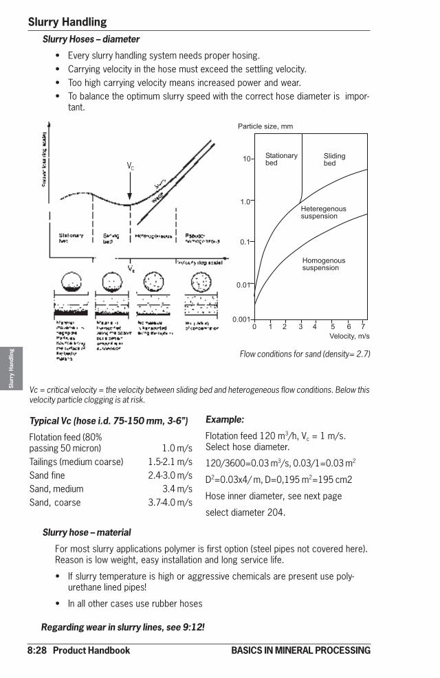
8:28 Product Handbook
Slurry HandlingSl
urry
Han
dlin
g
BASICS IN MINERAL PROCESSING
Slurry Hoses – diameter
• Every slurry handling system needs proper hosing.• Carrying velocity in the hose must exceed the settling velocity.• Too high carrying velocity means increased power and wear.• To balance the optimum slurry speed with the correct hose diameter is impor-
tant.
Vc = critical velocity = the velocity between sliding bed and heterogeneous flow conditions. Below thisvelocity particle clogging is at risk.
Typical Vc (hose i.d. 75-150 mm, 3-6”)
Flotation feed (80%passing 50 micron) 1.0 m/sTailings (medium coarse) 1.5-2.1 m/sSand fine 2.4-3.0 m/sSand, medium 3.4 m/sSand, coarse 3.7-4.0 m/s
Slurry hose – material
For most slurry applications polymer is first option (steel pipes not covered here).Reason is low weight, easy installation and long service life.
• If slurry temperature is high or aggressive chemicals are present use poly-urethane lined pipes!
• In all other cases use rubber hoses
Flow conditions for sand (density= 2.7)
VC
Regarding wear in slurry lines, see 9:12!
Example:
Flotation feed 120 m3/h, Vc = 1 m/s.Select hose diameter.
120/3600=0.03 m3/s, 0.03/1=0.03 m2
D2=0.03x4/ m, D=0,195 m2=195 cm2
Hose inner diameter, see next page
select diameter 204.
�&��'()#*'+#,��
��&�'-.&�!/#0
�)'0'.1/#0
�#�#�#1#.-2**2*"#.*'-.
�-�-1#.-2**2*"#.*'-.
�#)-('�!,� *��������
��
�3�
�3�
�3��
�3���
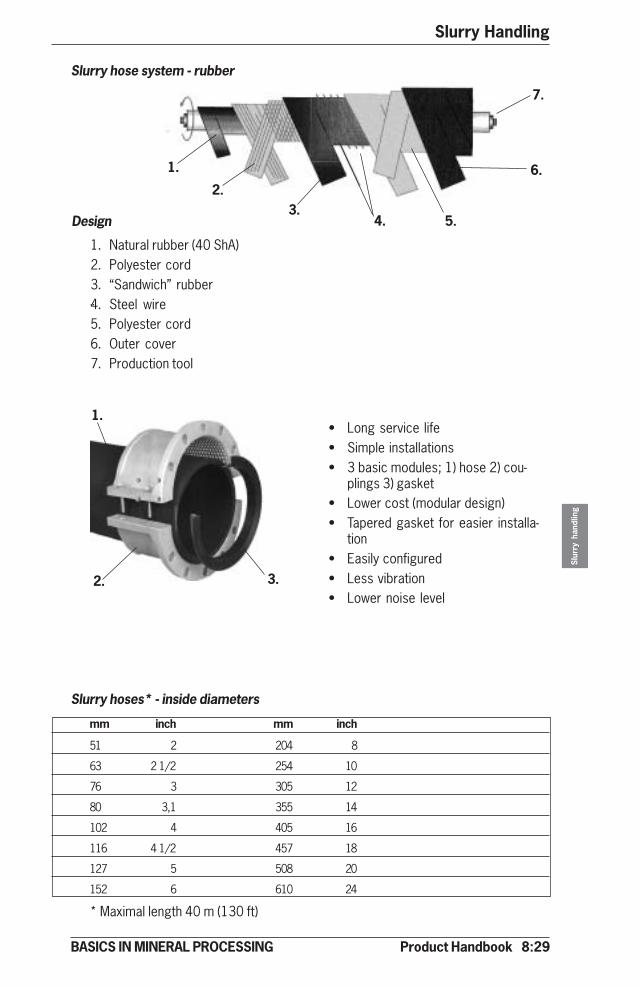
Product Handbook 8:29
Slurry Handling
Slur
ry h
andl
ing
BASICS IN MINERAL PROCESSING
Slurry hose system - rubber
¨
Slurry hoses* - inside diameters
mm inch mm inch
51 2 204 8
63 2 1/2 254 10
76 3 305 12
80 3,1 355 14
102 4 405 16
116 4 1/2 457 18
127 5 508 20
152 6 610 24
* Maximal length 40 m (130 ft)
Design
1. Natural rubber (40 ShA)2. Polyester cord3. “Sandwich” rubber4. Steel wire5. Polyester cord6. Outer cover7. Production tool
• Long service life• Simple installations• 3 basic modules; 1) hose 2) cou-
plings 3) gasket• Lower cost (modular design)• Tapered gasket for easier installa-
tion• Easily configured• Less vibration• Lower noise level
1.
2.3.
4. 5.
6.
7.
1.
2. 3.

8:30 Product Handbook
Slurry HandlingSl
urry
Han
dlin
g
BASICS IN MINERAL PROCESSING
� �
�
Technical Data Sheet
Model Inlet Outlet H L W Weight*mm (inch) mm (inch) mm (inch) mm (inch) mm (inch) ton
XM350 350 (14) 300 (12) 1 625 (64) 2 123 (84) 1 152 (45) 7,7
XM400 400 (16) 350 (14) 1 794 (80) 2 298 (91) 1 178 (46) 10,0
XM500 500 (20) 450 (18) 2 132 (84) 2 649 (104) 1 231 (49) 14,9
XM600 600 (24) 550 (22) 2 469 (97) 3 000 (118) 1 283 (51) 19,7
X800M 800 (32) 750 (30) TBA TBA TBA TBA
* Bare shaft weight
Slurry Pump - XR
Model Inlet Outlet H L W Weight*mm (inch) mm (inch) mm (inch) mm (inch) mm (inch) ton
XR350 350 (14) 300 (12) 1 939 (76 2 200 (87) 1 550 (61) 5,0
XR400 400 (16) 350 (14) 2 201 (87 2 200 (87) 1 550 (61) 7,5
XR500 500 (20) 450 (18) TBA TBA TBA TBA
* Bare shaft weight
Slurry Pump - XM
�
�
�

Product Handbook 8:31
Slurry Handling
Slur
ry h
andl
ing
BASICS IN MINERAL PROCESSING
� �
�
� �
�
Technical Data Sheet
Model Inlet Outlet H L W Weight*mm (inch) mm (inch) mm (inch) mm (inch) mm (inch) ton
HM50 50 (2) 32 (1,5) 433 (17) 702 (28) 360 (14) 0,17
HM75 75 (3) 50 (2) 438 (17) 732 (29) 360 (14) 0,20
HM100 100 (4) 75 (3) 505 (20) 870 (34) 424 (17) 0,32
HM150 150 (6) 100 (4) 630 (25) 1 025 (40) 545 (22) 0,55
HM200 200 (8) 150 (6) 855 (34) 1 257 (50) 685 (27) 1,22
HM250 250 (10) 200 (8) 1 030 (41) 1 460 (58) 816 (32) 2,04
HM300 300 (12) 250 (10) 1 142 (45) 1 600 (63) 1 000 (39) 2,85
* Bare shaft weight
Slurry Pump - HM
Model Inlet Outlet H L W Weight*mm (inch) mm (inch) mm (inch) mm (inch) mm (inch) ton
HR50 50 (2) 32 (1,5) 428 (17) 707 (28) 360 (14) 0,18
HR75 75 (3) 50 (2) 463 (18) 727 (29) 360 (14) 0,22
HR100 100 (4) 75 (3) 555 (22) 903 (36) 424 (17) 0,33
HR150 150 (6) 100 (4) 713 (28) 1 100 (43) 545 (22) 0,63
HR200 200 (8) 150 (6) 965 (38) 1 296 (51) 685 (27) 1,25
HR250 250 (10) 200 (8) 1 125 (44) 1 548 (61) 816 (32) 2,11
HR300 300 (12) 250 (10) 1 142 (57) 1 772 (70) 1 000 (39) 3,28
* Bare shaft weight
Slurry Pump - HR
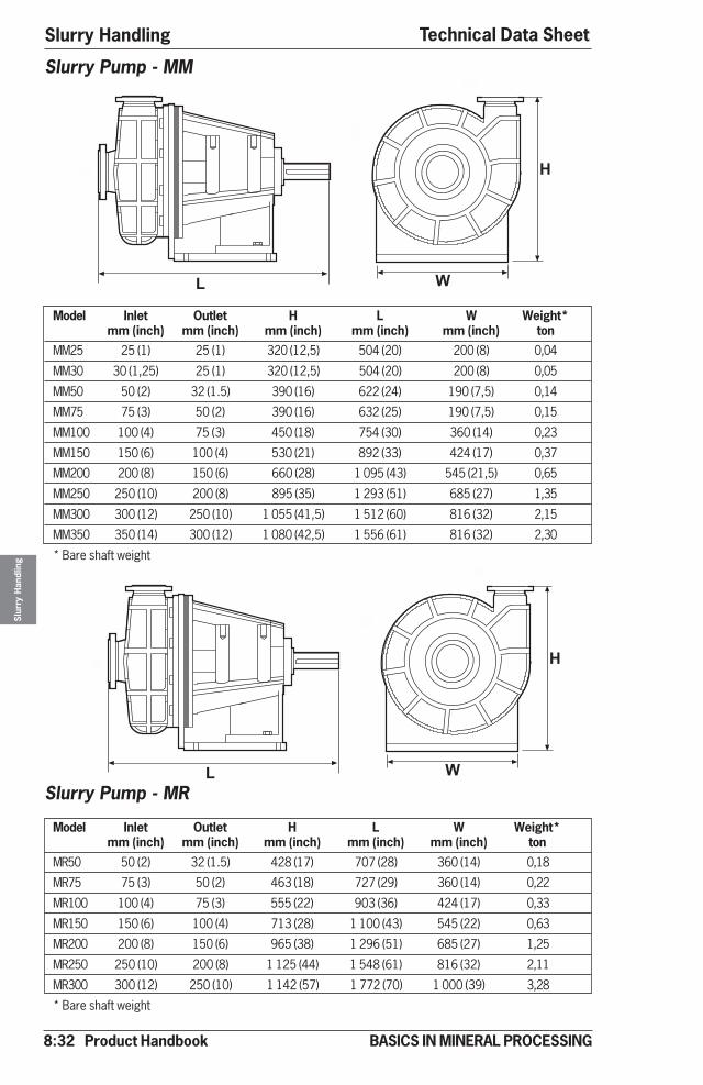
8:32 Product Handbook
Slurry HandlingSl
urry
Han
dlin
g
BASICS IN MINERAL PROCESSING
Technical Data Sheet
� �
�
� �
�
Model Inlet Outlet H L W Weight*mm (inch) mm (inch) mm (inch) mm (inch) mm (inch) ton
MM25 25 (1) 25 (1) 320 (12,5) 504 (20) 200 (8) 0,04
MM30 30 (1,25) 25 (1) 320 (12,5) 504 (20) 200 (8) 0,05
MM50 50 (2) 32 (1.5) 390 (16) 622 (24) 190 (7,5) 0,14
MM75 75 (3) 50 (2) 390 (16) 632 (25) 190 (7,5) 0,15
MM100 100 (4) 75 (3) 450 (18) 754 (30) 360 (14) 0,23
MM150 150 (6) 100 (4) 530 (21) 892 (33) 424 (17) 0,37
MM200 200 (8) 150 (6) 660 (28) 1 095 (43) 545 (21,5) 0,65
MM250 250 (10) 200 (8) 895 (35) 1 293 (51) 685 (27) 1,35
MM300 300 (12) 250 (10) 1 055 (41,5) 1 512 (60) 816 (32) 2,15
MM350 350 (14) 300 (12) 1 080 (42,5) 1 556 (61) 816 (32) 2,30
* Bare shaft weight
Slurry Pump - MM
Model Inlet Outlet H L W Weight*mm (inch) mm (inch) mm (inch) mm (inch) mm (inch) ton
MR50 50 (2) 32 (1.5) 428 (17) 707 (28) 360 (14) 0,18
MR75 75 (3) 50 (2) 463 (18) 727 (29) 360 (14) 0,22
MR100 100 (4) 75 (3) 555 (22) 903 (36) 424 (17) 0,33
MR150 150 (6) 100 (4) 713 (28) 1 100 (43) 545 (22) 0,63
MR200 200 (8) 150 (6) 965 (38) 1 296 (51) 685 (27) 1,25
MR250 250 (10) 200 (8) 1 125 (44) 1 548 (61) 816 (32) 2,11
MR300 300 (12) 250 (10) 1 142 (57) 1 772 (70) 1 000 (39) 3,28
* Bare shaft weight
Slurry Pump - MR
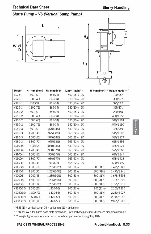
Product Handbook 8:33
Slurry Handling
Slur
ry h
andl
ing
BASICS IN MINERAL PROCESSING
�
��
��
�
��
Technical Data Sheet
Model* H1 mm (inch) H2 mm (inch) L mm (inch)** W mm (inch)**Weight kg/lb***VS25 (1) 800 (32) 585 (23) 400 (15¾) ØD 130/287VS25 (1) 1200 (48) 865 (34) 530 (20¾) ØD 350/772
VS25 (1) 1500(60) 865 (34) 530 (20¾) ØD 375/827VS25 (1) 1800 (72) 865 (34) 530 (20¾) ØD 395/871
VS50 (2) 800 (32) 585 (23) 400 (15¾) ØD 220/485VS50 (2) 1200 (48) 865 (34) 530 (20¾) ØD 480/1 058
VS50 (2) 1500 (60) 865 (34) 530 (20¾) ØD 510/1 124VS50 (2) 1800 (72) 865 (34) 530 (20¾) ØD 540/1 190
VS80 (3) 800 (32) 870 (34¼) 530 (20¾) ØD 435/959VS80 (3) 1 200 (48) 975 (38½) 565 (22¼) ØD 545/1 202
VS80 (3) 1 500 (60) 975 (38½) 565 (22¼) ØD 580/1 279VS80 (3) 1 800 (72) 975 (38½) 565 (22¼) ØD 615/1 356
VS100(4) 8 00 (32) 850 (33½) 530 (20¾) ØD 465/1 025VS100(4) 1 200 (48) 960 (37¾) 565 (22¼) ØD 575/1 268
VS100(4) 1 500 (60) 960 (37¾) 565 (22¼) ØD 610/1 345VS100(4) 1 800 (72) 960 (37¾) 565 (22¼) ØD 645/1 422
VS150(6) 1 200 (48) 965 (38) 565 (22¼) ØD 680/1 499VS150(6) 1 500 (60) 1 285 (50½) 800 (31½) 800 (31½) 1 415/3 120
VS150(6) 1 800 (72) 1 285 (50½) 800 (31½) 800 (31½) 1 470/3 241VS200(8) 1 200 (48) 1 285 (50½) 800 (31½) 800 (31½) 1 675/3 693
VS200(8) 1 500 (60) 1 285 (50½) 800 (31½) 800 (31½) 1 725/3 803VS200(8) 1 800 (72) 1 285 (50½) 800 (31½) 800 (31½) 1 775/3 913
VS250(10) 1 500 (60) 1 420 (56) 800 (31½) 800 (31½) 2 200/4 850VS250(10) 1 800(72) 1 420 (56) 800 (31½) 800 (31½) 2 280/5 027
VS300(12) 1 500(60) 1 420 (56) 800 (31½) 800 (31½) 2 745/6 052VS300(12) 1 800 (72) 1 420 (56) 800 (31½) 800 (31½) 2 825/6 228
*VS25 (1) = Vertical sump; 25 = outlet mm; (1) = outlet inch
** ØD or LxW is the pump base plate dimension. Optional base plate incl. discharge pipe also available.*** Weight figures are for metal parts. For rubber parts reduce weight by 10%.
Slurry Pump – VS (Vertical Sump Pump)
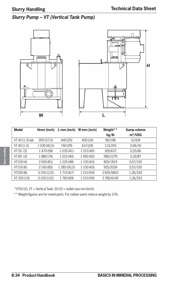
8:34 Product Handbook
Slurry HandlingSl
urry
Han
dlin
g
BASICS IN MINERAL PROCESSING
Technical Data Sheet
Model Hmm (inch) L mm (inch) W mm (inch) Weight** Sump volumekg/lb m³/USG
VT 40 (1.5) lab 955 (37,5) 640 (25) 400 (16) 90/198 0,03/8
VT 40 (1.5) 1 030 (40,5) 740 (29) 610 (24) 110/243 0,06/16
VT 50 (2) 1 470 (58) 1 035 (41) 1 010 (40) 305/672 0,25/66
VT 80 (3) 1 880 (74) 1 015 (40) 1 060 (42) 580/1279 0,33/87
VT100 (4) 2 050 (81) 1 225 (48) 1 100 (43) 825/1819 0,57/150
VT150 (6) 2 160 (85) 1 285 (50,5) 1 100 (43) 925/2039 0,57/150
VT200 (8) 3 105 (122) 1 710 (67) 1 510 (59) 2 655/5853 1,26/333
VT 250 (10) 3 105 (122) 1 760 (69) 1 510 (59) 2 785/6140 1,26/333
*VT50 (2), VT = Vertical Tank, 50 (2) = outlet size mm (inch).
** Weight figures are for metal parts. For rubber parts reduce weight by 10%.
Slurry Pump – VT (Vertical Tank Pump)
� �
�

Product Handbook 8:35
Slurry Handling
Slur
ry h
andl
ing
BASICS IN MINERAL PROCESSING
Technical Data Sheet
Model H mm (inch) W mm (inch) Weight** Sump volume kg/lb m³/USG
VF50 (2)* 1 600 (63) 800 (31) 355/783 0,14/37
VF80 (3) 2 250 (88) 1 000 (39) 605/1 334 0,37/98
VF100(4) 2 700 (106) 1 400 (55) 975/2 150 0,82/217
VF150(6) 2 700 (106) 1 400 (55) 1 095/2 414 0,82/217
VF200(8) 3 760 (148) 1 850 (73) 2 700/5 952 2,30/607
VF250(10) 3 760 (148) 1 850 (73) 2 900/6 392 2,30/607
VF350(14) 4 500 (177) 2 150 (85) 5 555/12 245 3,50/925
*VF50 (2), VF = Vertical Froth, 50 (2) = outlet size mm (inch).
** Weight figures are for metal parts. For rubber parts reduce weight by 10%.
Slurry Pump – VF (Vertical Froth Pump)
�
�

8:36 Product Handbook
Slurry HandlingSl
urry
Han
dlin
g
BASICS IN MINERAL PROCESSING
Technical Data Sheet
A D Hmm (ft) mm (ft) mm (ft)]1,25 (4) 1,25 (4) 1,85 (6)
1,50 (5) 1,50 (5) 2,10 (7)
1,75 (6) 1,75 (6) 2,35 (8)
2,00 (7) 2,00 (7) 2,70 (9)
2,50 (8) 2,50 (8) 3,20 (10)
3,00 (10) 3,00 (10) 3,80 (12)
3,50 (11) 3,50 (11) 4,40 (14)
4,00 (13) 4,00 (13) 4,90 (16)
4,50 (15) 4,50 (15) 5,50 (18)
5,00 (16) 5,00 (16) 6,10 (20)
6,00 (20) 6,00 (20) 7,10 (23)
6,00 (20) 7,00 (23) 7,30 (24)
7,00 (23) 8,00 (26) 8,50 (28)
8,00 (26) 9,00 (30) 9,70 (32)
9,00 (30) 10,00 (33) 10,70 (35)
11,00 (36) 12,00 (39) 1)
12,00 (39) 14,00 (46) 1)
1) Motor mounting may change for these sizes.
D
A
H
Agitator (Slurry Mixer)
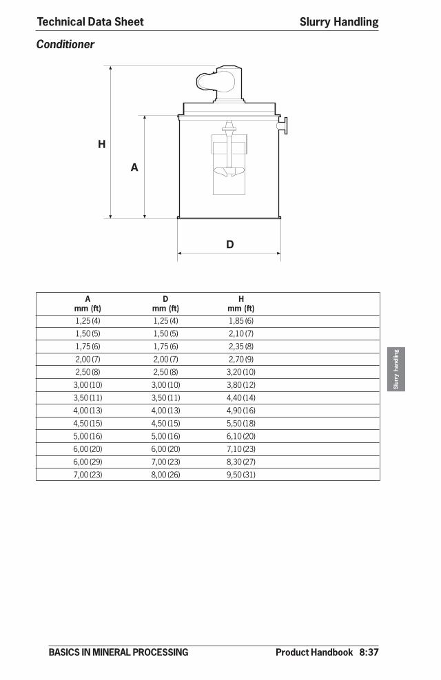
Product Handbook 8:37
Slurry Handling
Slur
ry h
andl
ing
BASICS IN MINERAL PROCESSING
Technical Data Sheet
A D Hmm (ft) mm (ft) mm (ft)1,25 (4) 1,25 (4) 1,85 (6)
1,50 (5) 1,50 (5) 2,10 (7)
1,75 (6) 1,75 (6) 2,35 (8)
2,00 (7) 2,00 (7) 2,70 (9)
2,50 (8) 2,50 (8) 3,20 (10)
3,00 (10) 3,00 (10) 3,80 (12)
3,50 (11) 3,50 (11) 4,40 (14)
4,00 (13) 4,00 (13) 4,90 (16)
4,50 (15) 4,50 (15) 5,50 (18)
5,00 (16) 5,00 (16) 6,10 (20)
6,00 (20) 6,00 (20) 7,10 (23)
6,00 (29) 7,00 (23) 8,30 (27)
7,00 (23) 8,00 (26) 9,50 (31)
Conditioner
A
D
H
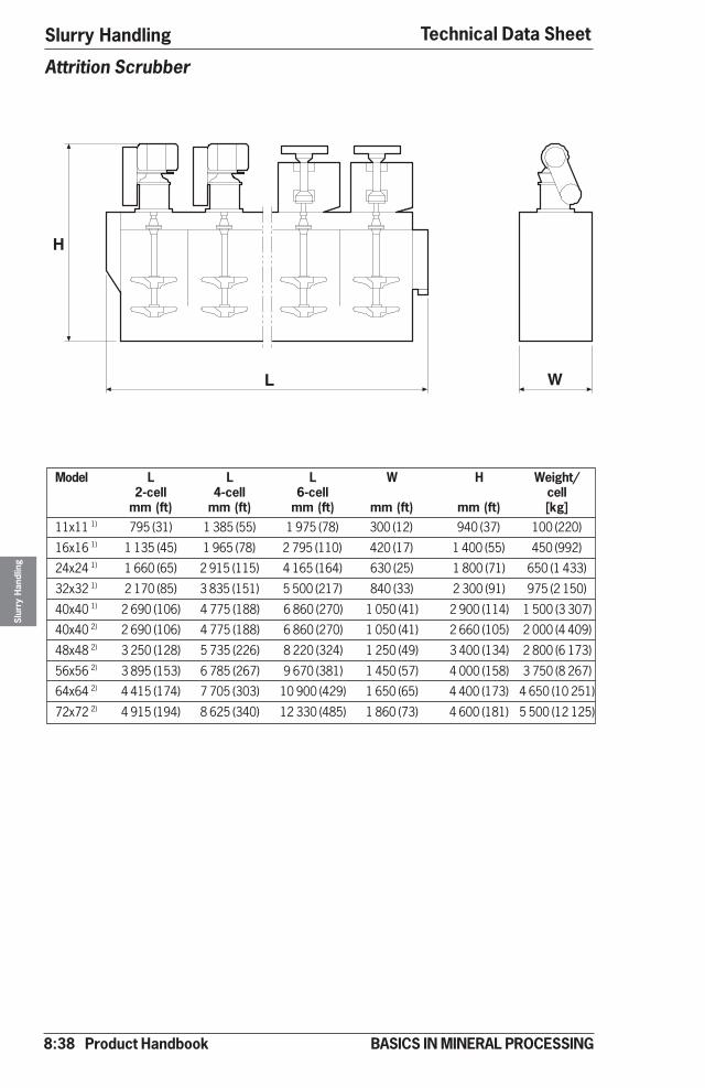
8:38 Product Handbook
Slurry HandlingSl
urry
Han
dlin
g
BASICS IN MINERAL PROCESSING
Technical Data Sheet
Attrition Scrubber
Model L L L W H Weight/2-cell 4-cell 6-cell cell
mm (ft) mm (ft) mm (ft) mm (ft) mm (ft) [kg]11x11 1) 795 (31) 1 385 (55) 1 975 (78) 300 (12) 940 (37) 100 (220)
16x16 1) 1 135 (45) 1 965 (78) 2 795 (110) 420 (17) 1 400 (55) 450 (992)
24x24 1) 1 660 (65) 2 915 (115) 4 165 (164) 630 (25) 1 800 (71) 650 (1 433)
32x32 1) 2 170 (85) 3 835 (151) 5 500 (217) 840 (33) 2 300 (91) 975 (2 150)
40x40 1) 2 690 (106) 4 775 (188) 6 860 (270) 1 050 (41) 2 900 (114) 1 500 (3 307)
40x40 2) 2 690 (106) 4 775 (188) 6 860 (270) 1 050 (41) 2 660 (105) 2 000 (4 409)
48x48 2) 3 250 (128) 5 735 (226) 8 220 (324) 1 250 (49) 3 400 (134) 2 800 (6 173)
56x56 2) 3 895 (153) 6 785 (267) 9 670 (381) 1 450 (57) 4 000 (158) 3 750 (8 267)
64x64 2) 4 415 (174) 7 705 (303) 10 900 (429) 1 650 (65) 4 400 (173) 4 650 (10 251)
72x72 2) 4 915 (194) 8 625 (340) 12 330 (485) 1 860 (73) 4 600 (181) 5 500 (12 125)
L W
H

Product Handbook 9:1
Wear in operation
Wea
r in
oper
atio
n
BASICS IN MINERAL PROCESSING
IntroductionMineral processing activities unavoidably result in wear. And wear costs money.Often lots of money. This is related to the structure of rock, ore or minerals, beingcrystals normally both hard and abrasive.
Why wear at all?
Wear is caused by the normal rock stress forces
• Compression (1)
• Impaction (2)
• Shearing (3)
• Attrition (4)
in combination with mineral hardness and energy!
Wear in operation
COMPRESSION
protected by
METALS
ManganeseSteel
SLIDINGIMPACTIONLOW VELOCITY <7m/s
IMPACTIONHIGH VELOCITY >7m/s
Ni hardNi-Cr white iron
High CromeCr white iron
Polymers
Rubber
Polyurethane
CERAMICS
1 2
3 4
caused by
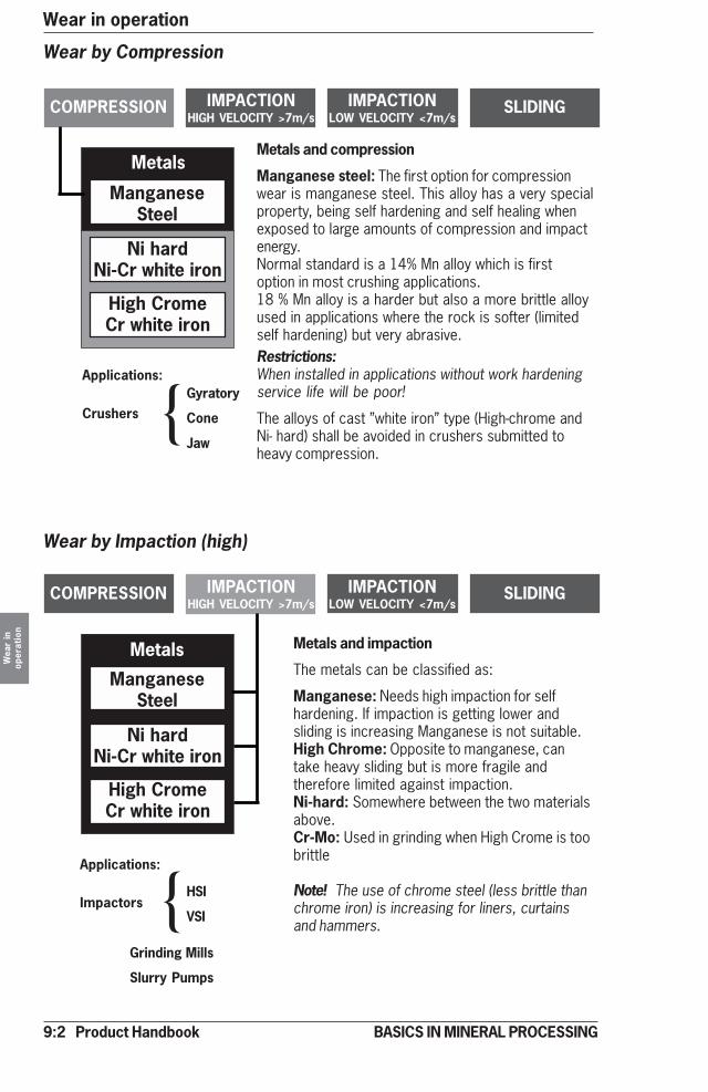
9:2 Product Handbook
Wear in operationW
ear
inop
erat
ion
BASICS IN MINERAL PROCESSING
COMPRESSION
Metals
ManganeseSteel
SLIDINGIMPACTIONLOW VELOCITY <7m/s
IMPACTIONHIGH VELOCITY >7m/s
Ni hardNi-Cr white iron
High CromeCr white iron
Wear by Compression
Applications:
CrushersGyratory
Cone
Jaw
Metals and compression
Manganese steel: The first option for compressionwear is manganese steel. This alloy has a very specialproperty, being self hardening and self healing whenexposed to large amounts of compression and impactenergy.Normal standard is a 14% Mn alloy which is firstoption in most crushing applications.18 % Mn alloy is a harder but also a more brittle alloyused in applications where the rock is softer (limitedself hardening) but very abrasive.Restrictions:When installed in applications without work hardeningservice life will be poor!
The alloys of cast ”white iron” type (High-chrome andNi- hard) shall be avoided in crushers submitted toheavy compression.
}COMPRESSION
Metals
ManganeseSteel
SLIDINGIMPACTIONLOW VELOCITY <7m/s
IMPACTIONHIGH VELOCITY >7m/s
Ni hardNi-Cr white iron
High CromeCr white iron
Applications:
Impactors
Grinding Mills
Slurry Pumps
HSI
VSI
Metals and impaction
The metals can be classified as:
Manganese: Needs high impaction for selfhardening. If impaction is getting lower andsliding is increasing Manganese is not suitable.High Chrome: Opposite to manganese, cantake heavy sliding but is more fragile andtherefore limited against impaction.Ni-hard: Somewhere between the two materialsabove.Cr-Mo: Used in grinding when High Crome is toobrittle
Note! The use of chrome steel (less brittle thanchrome iron) is increasing for liners, curtainsand hammers.
}
Wear by Impaction (high)

Product Handbook 9:3
Wear in operation
Wea
r in
oper
atio
n
BASICS IN MINERAL PROCESSING
COMPRESSION
Metals
Rubber
SLIDINGIMPACTIONLOW VELOCITY <7m/s
IMPACTIONHIGH VELOCITY >7m/s
Polyurethane
CERAMICS
Wear by Impaction (low)
Applications:Dump Trucks, Feeder hoppers,Transfer points, Grinding MillsSlurry pumps
Rubber and impactionFor low velocity impaction (material speedless than 7 m/s) SBR, styrene butadienerubber (60 ShA) is always the first choiceand will give the best cost effectiveness.The material is also very tolerant tomaterial size and is excellent for use ingrinding mills, dump trucks and primaryhoppers.
Restrictions:Look out for aromatic and fuel oils.Impact angles have to be considered, see9:4.
COMPRESSION
Polymers
Rubber
SLIDINGIMPACTIONLOW VELOCITY <7m/s
IMPACTIONHIGH VELOCITY >7m/s
Polyurethane
CERAMICS
Wear by Sliding
Applications:Chutes, Spouts
Rubber and slidingNatural rubber is an outstanding option for thesliding abrasion of small, hard and sharpparticles. Also for wet conditions.
Restrictions:If sliding speed is exceeding 7 m/s (dry appli-cations) temperature can start to rise andcause damage. Besides temperature oil isalways a threat.
Polyurethane and slidingBest option for tough sliding applications whenparticle size is lower than 50 mm. Excellent inwet applications. Tolerant to chemicals and oil.
Restrictions:Large sizes and high velocity might cause problems.
Ceramics and slidingThe natural choice when mission is too hard for the options above. Hardness,resistance to temperature and corrosion plus low weight gives a masterpiece forsliding.Al203 (Aluminium oxide) is the most cost-effective material.
Restrictions:Impaction is dangerous for ceramics (cracking) and must be avoided. Combinationceramics + rubber is an option. Composition and quality can vary from supplier tosupplier.
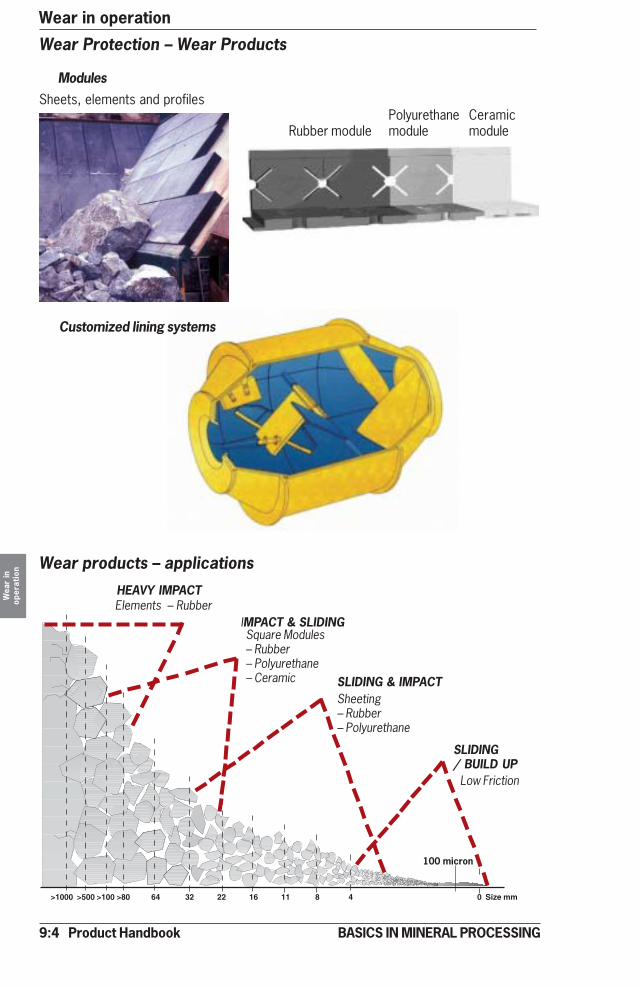
9:4 Product Handbook
Wear in operationW
ear
inop
erat
ion
BASICS IN MINERAL PROCESSING
Wear Protection – Wear Products
Modules
Rubber modulePolyurethanemodule
Ceramicmodule
Sheets, elements and profiles
Customized lining systems
>1000 >500 >100 >80 64 32 22 16 11 8 4 0 Size mm
100 micron
HEAVY IMPACT
IMPACT & SLIDING
SLIDING & IMPACT
SLIDING/ BUILD UP
Elements – Rubber
Square Modules– Rubber– Polyurethane– Ceramic
Sheeting– Rubber– Polyurethane
Low Friction
Wear products – applications
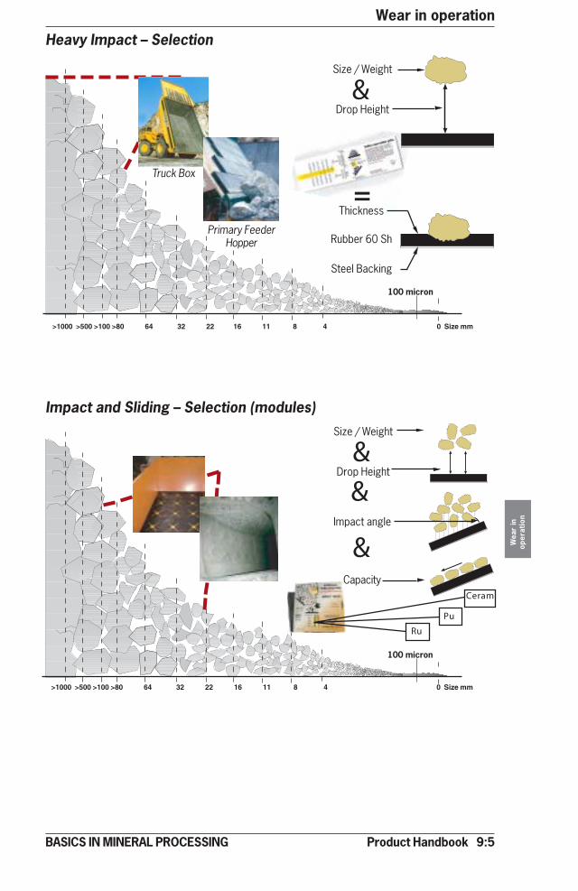
Product Handbook 9:5
Wear in operation
Wea
r in
oper
atio
n
BASICS IN MINERAL PROCESSING
100 micron
Heavy Impact – Selection
Truck Box
Primary FeederHopper
Thickness
Rubber 60 Sh
Steel Backing
Size / Weight
Drop Height
=
&
Impact and Sliding – Selection (modules)
>1000 >500 >100 >80 64 32 22 16 11 8 4 0 Size mm
100 micron
>1000 >500 >100 >80 64 32 22 16 11 8 4 0 Size mm
Impact angle
Capacity
Size / Weight
Drop Height&
&
&
Ru
Pu
Ceram

9:6 Product Handbook
Wear in operationW
ear
inop
erat
ion
BASICS IN MINERAL PROCESSING
Impact and sliding – Selection (sheeting)
>1000 >500 >100 >80 64 32 22 16 11 8 4 0 Size mm
100 micron
Impact angle
Capacity
Size / Weight
Drop Height&
&
&
=
Sliding and build up – selection
>1000 >500 >100 >80 64 32 22 16 11 8 4 0 Size mm
100 micron
Thickness
MATERIAL THICKNESS
mm mm
<20 3 - 10
<35 10 - 25
<70 25 - 40
Low Friction Elements – UHMWPE**Ultra high Molecule Weight Poly Ethylene
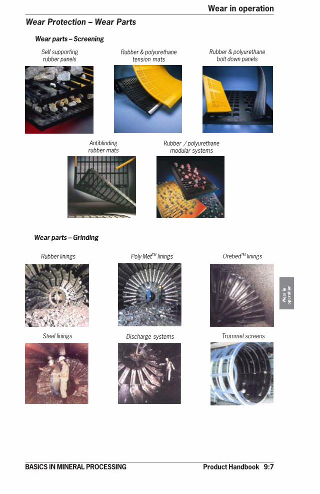
Product Handbook 9:7
Wear in operation
Wea
r in
oper
atio
n
BASICS IN MINERAL PROCESSING
Wear Protection – Wear Parts
Wear parts – Screening
Self supportingrubber panels
Rubber & polyurethanetension mats
Rubber & polyurethanebolt down panels
Antiblindingrubber mats
Rubber / polyurethanemodular systems
Rubber linings Poly-MetTM linings OrebedTM linings
Steel linings Discharge systems Trommel screens
Wear parts – Grinding
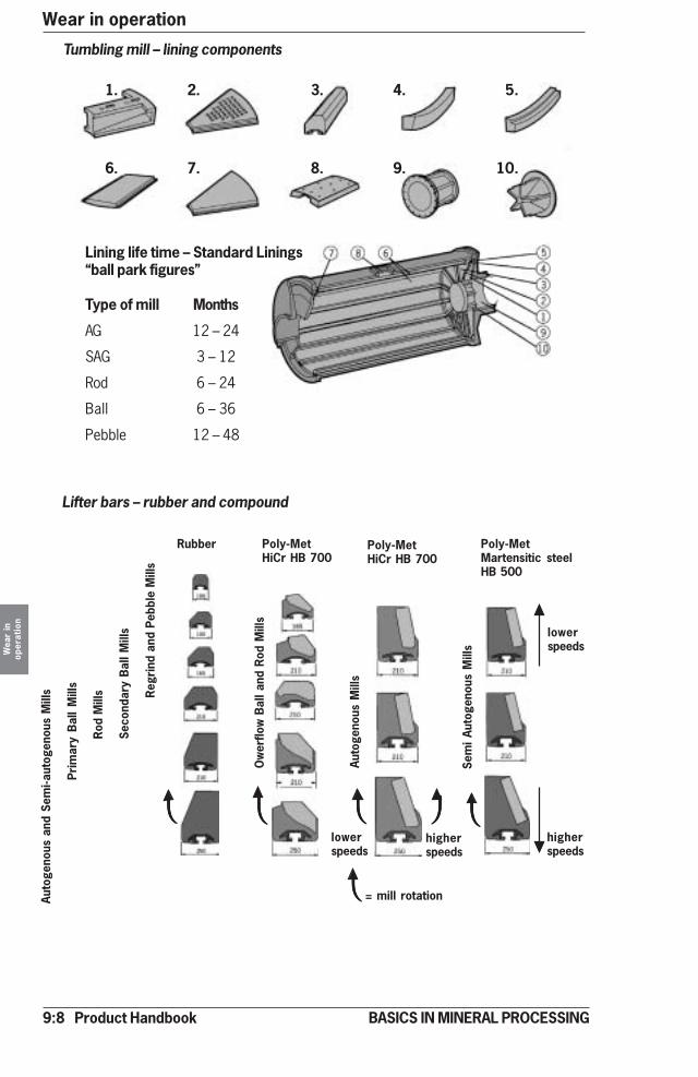
9:8 Product Handbook
Wear in operationW
ear
inop
erat
ion
BASICS IN MINERAL PROCESSING
Tumbling mill – lining components
Lining life time – Standard Linings“ball park figures”
Type of mill Months
AG 12 – 24
SAG 3 – 12
Rod 6 – 24
Ball 6 – 36
Pebble 12 – 48
1. 2. 3. 4. 5.
6. 7. 8. 9. 10.
Lifter bars – rubber and compound
Auto
geno
us a
nd S
emi-a
utog
enou
s M
ills
Prim
ary
Bal
l M
ills
Rod
Mill
s
Seco
ndar
y B
all M
ills
Reg
rind
and
Peb
ble
Mill
s
Rubber Poly-MetHiCr HB 700
Poly-MetHiCr HB 700
Ow
erflo
w B
all a
nd R
od M
ills
Auto
geno
us M
ills
Poly-MetMartensitic steelHB 500
Sem
i Au
toge
nous
Mill
s
higherspeeds
lowerspeeds
higherspeeds
lowerspeeds
= mill rotation

Product Handbook 9:9
Wear in operation
Wea
r in
oper
atio
n
BASICS IN MINERAL PROCESSING
AG and SAG mills Rod mills
Dry: Metal (white iron700 Br)
Wet: Metal (white iron700 Br)or Poly Met (700 Br)
Dry: Metal (Cr-Mo350 Br)
Wet: Metal (Cr-Mo350 Br)or Poly Met(500 Br)
Dry: Metal (white iron 700 Br)Wet: Metal (white iron 700 Br)
Rubber and Poly Met,(Poly Met at mill ends)
Dry: Metal (or rubber if temperaturenot critical)
Wet: Rubber (Secondary and re-grind) Poly Met (700 Br)
Dry-rod: Metal
Dry-ball: Metal (or rubber iftemperature not critical)
Wet-rod: Metal
Wet-ball:Rubber
Tumbling mill liners– material
Ball and Pebble mills SRR mills
VERTIMILL® – Liners
Screw – metal with Nihard linersChamber – Orebed magnetic liner
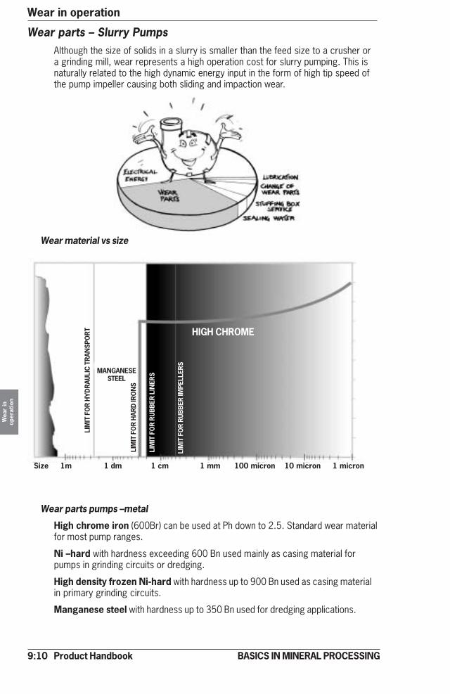
9:10 Product Handbook
Wear in operationW
ear
inop
erat
ion
BASICS IN MINERAL PROCESSING
Wear parts – Slurry PumpsAlthough the size of solids in a slurry is smaller than the feed size to a crusher ora grinding mill, wear represents a high operation cost for slurry pumping. This isnaturally related to the high dynamic energy input in the form of high tip speed ofthe pump impeller causing both sliding and impaction wear.
Wear material vs size
Wear parts pumps –metal
High chrome iron (600Br) can be used at Ph down to 2.5. Standard wear materialfor most pump ranges.
Ni –hard with hardness exceeding 600 Bn used mainly as casing material forpumps in grinding circuits or dredging.
High density frozen Ni-hard with hardness up to 900 Bn used as casing materialin primary grinding circuits.
Manganese steel with hardness up to 350 Bn used for dredging applications.
Size 1m 1 dm 1 cm 1 mm 100 micron 10 micron 1 micron
LIM
IT F
OR
HYD
RAU
LIC
TR
ANSP
OR
T HIGH CHROME
LIM
IT F
OR
HAR
D IR
ON
S
LIM
IT F
OR
RUB
BER
LIN
ERS
LIM
IT F
OR
RUB
BER
IMPE
LLER
S
MANGANESESTEEL

Product Handbook 9:11
Wear in operation
Wea
r in
oper
atio
n
BASICS IN MINERAL PROCESSING
Material Physical Chemical Thermalproperties properties properties
Max. Wear Hot water, Strong and Oils, Highest serviceImpeller Tip resistance diluted acids oxidising hydro temp.(oC)
Speed acids carbons Contin. Occasion.(m/s)
Elasta family 27 Very good Excellent Fair Bad (-50) to 65 100
(Natural rubber)
MeroPrene 452 27 Good Excellent Fair Good 90 120
(Chloroprene type)
MeroLen 016 30 Good Excellent Good Bad 100 130
(EPDM type)
MeroTyle 30 Fair Excellent Good Bad 100 130
(Butyl type)
MeroThane 30 Very good Fair Bad Good 45-50 65
Polyurethane
Wear parts pumps – elastomers
Something About Ceramic LinersAlthough ceramics have high resistance against wear, temperature and mostchemicals, they have never really been accepted as day-to-day standards inSlurry Pumping.
Being both brittle and expensive to manufacture.
Development work on ceramics continue in an attempt to improve the possibleacceptance.
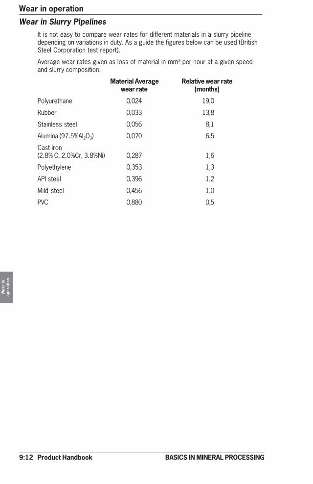
9:12 Product Handbook
Wear in operationW
ear
inop
erat
ion
BASICS IN MINERAL PROCESSING
Wear in Slurry PipelinesIt is not easy to compare wear rates for different materials in a slurry pipelinedepending on variations in duty. As a guide the figures below can be used (BritishSteel Corporation test report).
Average wear rates given as loss of material in mm³ per hour at a given speedand slurry composition.
Material Average Relative wear ratewear rate (months)
Polyurethane 0,024 19,0
Rubber 0,033 13,8
Stainless steel 0,056 8,1
Alumina (97.5%Al2O3) 0,070 6,5
Cast iron(2.8% C, 2.0%Cr, 3.8%Ni) 0,287 1,6
Polyethylene 0,353 1,3
API steel 0,396 1,2
Mild steel 0,456 1,0
PVC 0,880 0,5

Product Handbook 10:1
Operation and environment
Ope
ratio
n an
den
viro
nmen
t
BASICS IN MINERAL PROCESSING
Operation and Environment – IntroductionFrom environmental, health and safety point of view most mineral processingoperations have some negative affects on the working environment.
The main problems are related to
• Dust (dry plants)
• Noise (wet and dry plants)
• Pollution (emissions other than dust to air and water)
Regarding pollution of water and air by various emissions we refer to the processsections 5 and 6 above (enrichment and upgrading).
Dust
Dust - size
When energy is introduced to rock, ore or mineral crystals will generate a dustemission. With dust in mineral processing we practically understand particlesbelow 100 micron in size. Above this size dry particles are easy to control andare quite harmless.
Dust - Chemical composition
A parameter of interest is the chemical composition. Hard rock in many cases ishazardous due to the silica content.
Free quarts (SiO2) is extremely dangerous and so are the rocks containing quartslike granite, gneiss a.o, see figure below. Fine silica can cause silicosis, a deadlylung disease. Mg-silicate of asbestos type is also very dangerous when inhaled,causing lung cancer.
As many of the silicates are hard and abrasive these dust fractions also arecausing heavy wear when exposed to bearings, motors etc.
Dust fractions of non -silica type are normallynot too dangerous for theoperators and give morelika a “housekeeping”problem.
Gra
nite
Rhy
olite
Dior
ite A
ndes
ite
Gab
bro
Basa
lt
SiO2
Abrasion curve
K-Feld
spar
Quartz
Na, Ca
Felds
par
Ferro
magne
sian
mineral
s
70% SiO2 by weight
60
50
40
100% Mineralby volume
80
60
40
20
�
�
�
Surface (fine)
Deep (coarse)
Biotite Olivine
Dust – SiO2 levels
SiO2 levels in magmatic rock
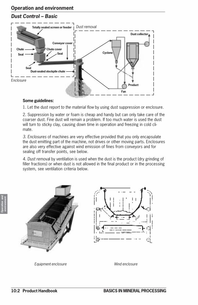
10:2 Product Handbook
Operation and environmentO
pera
tion
and
envi
ronm
ent
BASICS IN MINERAL PROCESSING
Dust Control – Basic
1. Let the dust report to the material flow by using dust suppression or enclosure.
2. Suppression by water or foam is cheap and handy but can only take care of thecoarser dust. Fine dust will remain a problem. If too much water is used the dustwill turn to sticky clay, causing down time in operation and freezing in cold cli-mate.
3. Enclosures of machines are very effective provided that you only encapsulatethe dust emitting part of the machine, not drives or other moving parts. Enclosuresare also very effective against wind emission of fines from conveyors and forsealing off transfer points, see below.
4. Dust removal by ventilation is used when the dust is the product (dry grinding offiller fractions) or when dust is not allowed in the final product or in the processingsystem, see ventilation criteria below.
Cyclone
Fan
Product
Totally sealed screen or feeder
Chute coverSeal
Seal
Chute
Seal
Conveyor cover
Dust collector
Dust-sealed stockpile chute
Equipment enclosure Wind enclosure
Dust removal
Enclosure
Some guidelines:
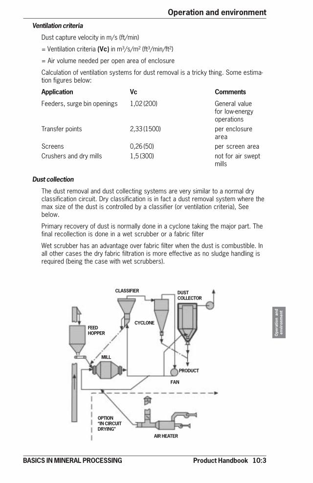
Product Handbook 10:3
Operation and environment
Ope
ratio
n an
den
viro
nmen
t
BASICS IN MINERAL PROCESSING
Ventilation criteria
Dust capture velocity in m/s (ft/min)
= Ventilation criteria (Vc) in m³/s/m² (ft³/min/ft²)
= Air volume needed per open area of enclosure
Calculation of ventilation systems for dust removal is a tricky thing. Some estima-tion figures below:
Application Vc Comments
Feeders, surge bin openings 1,02 (200) General valuefor low-energyoperations
Transfer points 2,33 (1500) per enclosurearea
Screens 0,26 (50) per screen areaCrushers and dry mills 1,5 (300) not for air swept
mills
Dust collection
The dust removal and dust collecting systems are very similar to a normal dryclassification circuit. Dry classification is in fact a dust removal system where themax size of the dust is controlled by a classifier (or ventilation criteria), Seebelow.
Primary recovery of dust is normally done in a cyclone taking the major part. Thefinal recollection is done in a wet scrubber or a fabric filter
Wet scrubber has an advantage over fabric filter when the dust is combustible. Inall other cases the dry fabric filtration is more effective as no sludge handling isrequired (being the case with wet scrubbers).
FEEDHOPPER
CLASSIFIER DUSTCOLLECTOR
CYCLONE
MILL
FAN
PRODUCT
OPTION“IN CIRCUITDRYING”
AIR HEATER

10:4 Product Handbook
Operation and environmentO
pera
tion
and
envi
ronm
ent
BASICS IN MINERAL PROCESSING
Noise
General
In mineral processing there are a number of machines considered to be very noisy(crushers, screens and grinding mills are typical).
By definition noise is an “undesirable” sound. As sound is air borne sound pres-sure variations, we have to find a sound pressure level, which can be tolerated bythe operators. Noise is not only harmful to the hearing but also affects the heartaction and the ability of concentration. It also restricts verbal communication andthe observation of warning signals or dangerous situations.
Sound – basic
The human sound pressure range from lowest sound to be heard and highestsound to stand without pain isfrom 0,00002Pa (2µPa) to 20 Pa. (1 psi = 6,89kPa).
To be more practical the sound pressure range above is converted to a soundpressure level by the formula:
Lp = 20x log P/Po (Po = 2 µPa) converting the range above over to 0-120 dB(decibel)!
Experienced sound change of dBDouble sound level + 10dBDouble sound sources + 3 dBDouble the distance to sound source - 6 dB
Hearing range for a normal ear
The lower limit is called the threshold of hearing and has a maximum sensitivityaround 3500 Hz (resonance frequency of the ear).
The upper line is the 120 dB sound pressure line (the pain line)
Mechanical noise is measured in dB (A) indicating that an A-filter is used,damping lower frequencies (of less harm to the operators).Infra-sound is sound with a frequency below 22 Hz. (Can be harmful at longerexposures)Ultra-sound is sound with a frequency above 18 kHz. (Can be harmful at longerexposures)
Speach
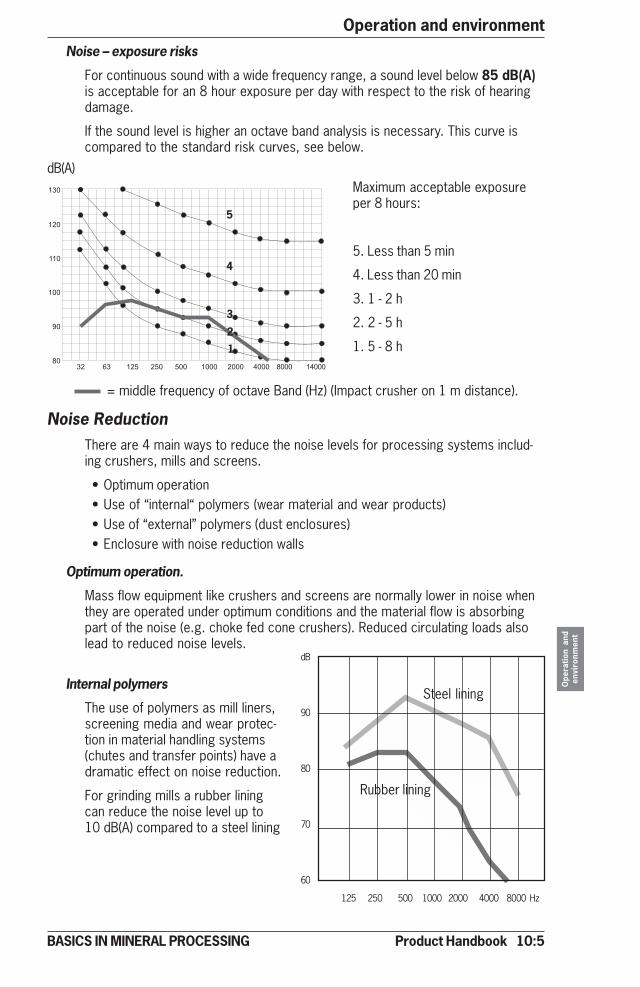
Product Handbook 10:5
Operation and environment
Ope
ratio
n an
den
viro
nmen
t
BASICS IN MINERAL PROCESSING
Noise ReductionThere are 4 main ways to reduce the noise levels for processing systems includ-ing crushers, mills and screens.
• Optimum operation• Use of “internal“ polymers (wear material and wear products)• Use of “external” polymers (dust enclosures)• Enclosure with noise reduction walls
Optimum operation.
Mass flow equipment like crushers and screens are normally lower in noise whenthey are operated under optimum conditions and the material flow is absorbingpart of the noise (e.g. choke fed cone crushers). Reduced circulating loads alsolead to reduced noise levels.
Noise – exposure risks
For continuous sound with a wide frequency range, a sound level below 85 dB(A)is acceptable for an 8 hour exposure per day with respect to the risk of hearingdamage.
If the sound level is higher an octave band analysis is necessary. This curve iscompared to the standard risk curves, see below.
���
���
���
���
��
���� ���� ����������������������������������������� ���� ������������������
= middle frequency of octave Band (Hz) (Impact crusher on 1 m distance).
Maximum acceptable exposureper 8 hours:
5. Less than 5 min
4. Less than 20 min
3. 1 - 2 h
2. 2 - 5 h
1. 5 - 8 h12
3
4
5
Internal polymers
The use of polymers as mill liners,screening media and wear protec-tion in material handling systems(chutes and transfer points) have adramatic effect on noise reduction.
For grinding mills a rubber liningcan reduce the noise level up to10 dB(A) compared to a steel lining
dB
90
80
70
60
125 250 500 1000 2000 4000 8000 Hz
dB(A)
Steel lining
Rubber lining
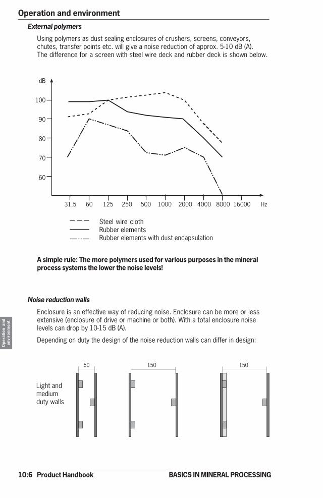
10:6 Product Handbook
Operation and environmentO
pera
tion
and
envi
ronm
ent
BASICS IN MINERAL PROCESSING
External polymers
Using polymers as dust sealing enclosures of crushers, screens, conveyors,chutes, transfer points etc. will give a noise reduction of approx. 5-10 dB (A).The difference for a screen with steel wire deck and rubber deck is shown below.
A simple rule: The more polymers used for various purposes in the mineralprocess systems the lower the noise levels!
Noise reduction walls
Enclosure is an effective way of reducing noise. Enclosure can be more or lessextensive (enclosure of drive or machine or both). With a total enclosure noiselevels can drop by 10-15 dB (A).
Depending on duty the design of the noise reduction walls can differ in design:
���� ������������������������������������������������� �������������������
�
���
��
�
��
��
Steel wire clothRubber elementsRubber elements with dust encapsulation
50 150 150
Light andmediumduty walls
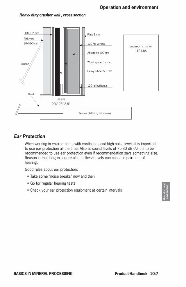
Product Handbook 10:7
Operation and environment
Ope
ratio
n an
den
viro
nmen
t
BASICS IN MINERAL PROCESSING
Heavy duty crusher wall , cross section
Plate 1,2 mm
RHS vert.
80x40x3 mm
Support
Weld
Beam200” 75” 8,5”
Service platform, not moving
Plate 1 mm
120-rail vertical
Absorbent 100 mm
Wood spacer 19 mm
Heavy rubber 5,2 mm
120-rail horizontal
Superior crusher112 DbA
Ear ProtectionWhen working in environments with continuous and high noise levels it is importantto use ear protection all the time. Also at sound levels of 75-80 dB (A) it is to berecommended to use ear protection even if recommendation says something else.Reason is that long exposure also at these levels can cause impairment ofhearing.
Good rules about ear protection:
• Take some “noise breaks” now and then
• Go for regular hearing tests
• Check your ear protection equipment at certain intervals
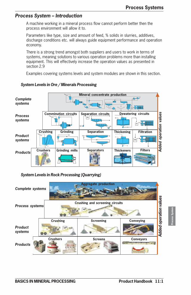
Product Handbook 11:1
Process Systems
Proc
ess
Syst
em
BASICS IN MINERAL PROCESSING
Process System – IntroductionA machine working in a mineral process flow cannot perform better then theprocess environment will allow it to.
Parameters like type, size and amount of feed, % solids in slurries, additives,discharge conditions etc. will always guide equipment performance and operationeconomy.
There is a strong trend amongst both suppliers and users to work in terms ofsystems, meaning solutions to various operation problems more than installingequipment. This will effectively increase the operation values as presented insection 2.9
Examples covering systems levels and system modules are shown in this section.
Completesystems
Processsystems
Productsystems
Products
Mineral concentrate production
Comminution circuits
Crushing Grinding Filtration
Adde
d op
erat
ion
valu
esSeparation circuits
Separation Thickening
Crushers Grinding mills FiltersSeparators Thickeners
Dewatering circuits
Complete systems
Process systems
Productsystems
Products
Aggregate production
Crushing Screening Conveying
Crushers Screens Conveyors
Adde
d op
erat
ion
valu
es
Crushing and screening circuits
System Levels in Rock Processing (Quarrying)
System Levels in Ore / Minerals Processing
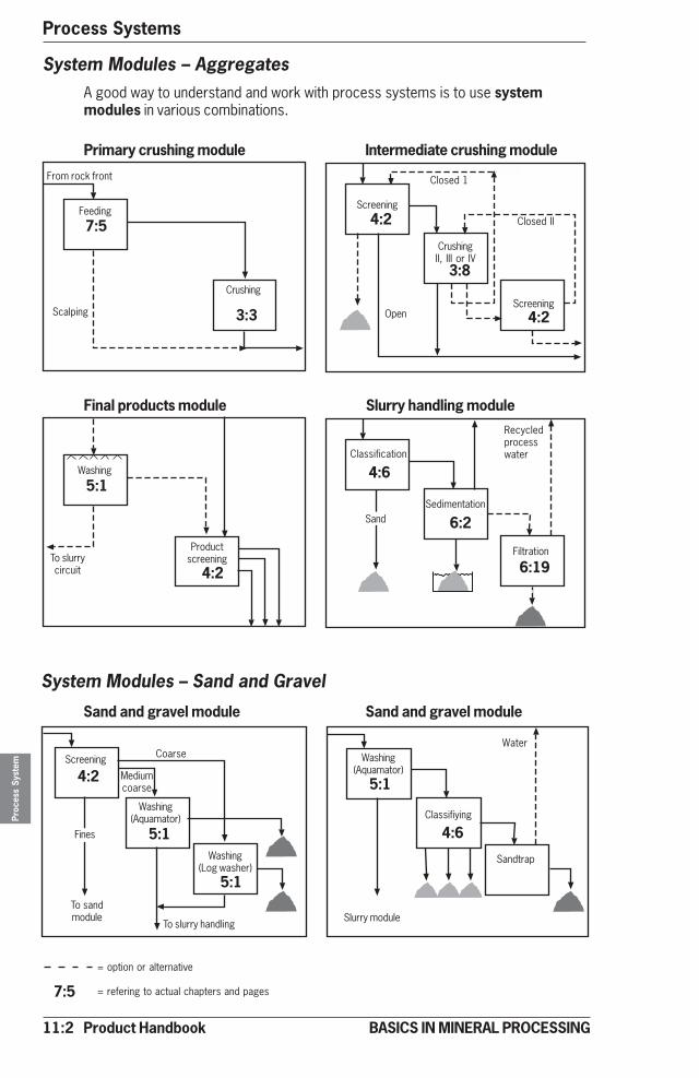
11:2 Product Handbook
Process SystemsPr
oces
s Sy
stem
BASICS IN MINERAL PROCESSING
System Modules – Sand and Gravel
Sand and gravel module Sand and gravel module
Screening
Washing(Aquamator)
Washing(Log washer)
Fines
To sandmodule
To slurry handling
Coarse
Mediumcoarse
Washing(Aquamator)
Classifiying
Sandtrap
Slurry module
4:2
5:1
5:1
5:1
4:6
Water
Primary crushing module Intermediate crushing module
From rock front
Feeding
Crushing
Scalping
Closed 1
Screening
CrushingII, III or IV
Screening
Closed II
Open
Final products module Slurry handling module
Washing
To slurrycircuit
Productscreening
Classification
Sedimentation
Filtration
Sand
Recycledprocesswater
= option or alternative
= refering to actual chapters and pages7:5
3:3
4:2
4:2
3:8
5:1
4:2
4:6
6:2
6:19
System Modules – AggregatesA good way to understand and work with process systems is to use systemmodules in various combinations.
7:5
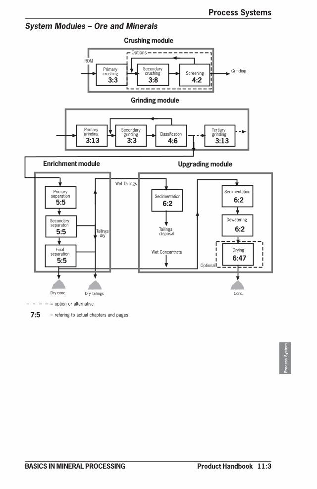
Product Handbook 11:3
Process Systems
Proc
ess
Syst
em
BASICS IN MINERAL PROCESSING
System Modules – Ore and Minerals
������������
��������
����
�������������������
���������
����������������
��������������
�������
������ ��������
��������������
���������� �
������ ����
������� ������
�������� ������ �������������
�������� ������
���
��������������
��������������� ��������
������
�������
Crushing module
Grinding module
Enrichment module Upgrading module
3:3 3:8 4:2
3:13 3:3 4:6 3:13
5:5
5:5
5:5
6:2 6:2
6:2
6:47
Dry conc. Dry tailings Conc.
= option or alternative
= refering to actual chapters and pages7:5
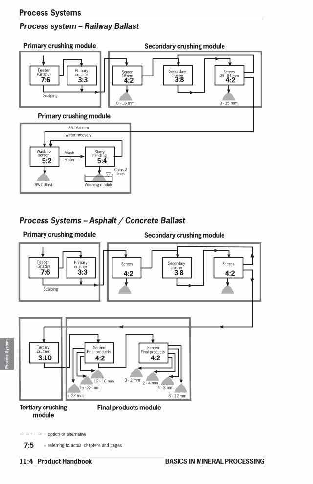
11:4 Product Handbook
Process SystemsPr
oces
s Sy
stem
BASICS IN MINERAL PROCESSING
Process system – Railway Ballast
Process Systems – Asphalt / Concrete Ballast
������ ���!!��"
��������������
������#$���
���������������
������%&�'�()���
�������
*�'�#$��� *�'�%&���
������ ������
�������������
����
�����
%&�'�()���
������+�����
���������,���
��'-������ ������ ������
Primary crushing module Secondary crushing module
Primary crushing module
������ ���!!��"
��������������
������ ���������������
������
���������������
�������������������
#(�'�..���
�������
/�..���
�������������������
#.�'�#(���
$�'�#.���
)�'�$���.�'�)���
*�'�.���
Primary crushing module Secondary crushing module
Tertiary crushingmodule
Final products module
7:6 3:3 4:2 3:8 4:2
5:2 5:4
7:6 3:3 4:2 3:8 4:2
3:10 4:2 4:2
= option or alternative
= referring to actual chapters and pages7:5

Product Handbook 11:5
Process Systems
Proc
ess
Syst
em
BASICS IN MINERAL PROCESSING
�����������������
���������������
�������� ������� ������
�������� ������
�������������
��������
������������01������
�������
������������������������������
1������2
���������2
������������
���� ���������������
��� ��3�4��3�4��� �����������5���4���--�� ���������6������
�������
���2�7��
��������
3���������,��
��,�������
�����������������
������ �
������2��������
8���
�������
��������������
���������2
��������
������2���������
��������������,�������2
1�������������
�������!�� � ������"
������ �������
3����������2
Process System – Ferrous Ore (hosting apatite)
Process System – Base Metal Ore
3:3 3:8 4:2 3:13 3:13 4:6
5:24
5:13
6:2
6:30
5:31
5:18
6:2
6:30
6:3
6:11 6:30
6:55
��������������2
�� ����
�������������
������������������
������2
���������2
���� ���������������
��������
��,�������
�����������������
������ �
������2��������
���������-����2
�� ����
�������������
������������������
��������
�-����2���������
��,�������2
������ ���������
��,�������
������������
������������
�-����2
��������9�����
�� ����
�������������
������������
9�����2��������� ��������
������������
9�����2
�����������������
���������������
�������� ������� ������
�������� ������
�������������
������������
��� ��3�4��3�4��� �����������5���4���--�� ���������6������
�������
���2�7��
= option or alternative ’ :5 = referring to actual chapters and pages
3:3 3:8 4:2 3:13 3:13 4:6
5:13
3:13
5:3
6:30
5:17
5:13
3:13
6:3
6:30
5:13
5:13
3:13
6:3
6:3
5:13
6:30
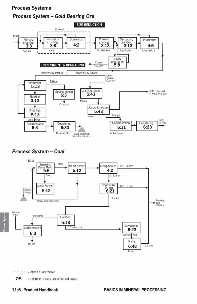
11:6 Product Handbook
Process SystemsPr
oces
s Sy
stem
BASICS IN MINERAL PROCESSING
Process System – Gold Bearing Ore
Process System – Coal
���� ���������������
���,�����������������
����� ��
���,����-���������
�����������2
�� ����
���������2
��:���
������ �
���2��������
���������������
��������
������
������ �
������������������������-�
1�������������
������������
������������
���������������-��;���������
0������ ���� ��
3����������� ��
������������ ��������
���,����-���������
����������� �
��:���
0������-��������
�����������������
���������������
�������� ������� ������
�������� ������
�������������
������������
��� ��3�4��3�4��� �����������5���4���--�� ���������6������
�������
���2�7��
3:3 3:8 4:2 3:13 3:13 4:6
5:13
3:13
5:13
6:3
6:3
6:30
5:43
5:43
6:236:11
5:8
������������
���������� ������������ ��!�� �������
�������� ������
������������
�������
����
5������ ������� �
��������
����
#.�'�#.&���
*2&�'�#.���
<���������������
*�'�#.���
'�*2&���
'�*2&���
1�������
'�*2&����������
���;
����������� �
8��,�����������,���
������������
����������� �
������ �
������������
= option or alternative
= referring to actual chapters and pages7:5
5:6 5:12 4:2
5:12 6:21
6:3
5:13
6:23
6:48
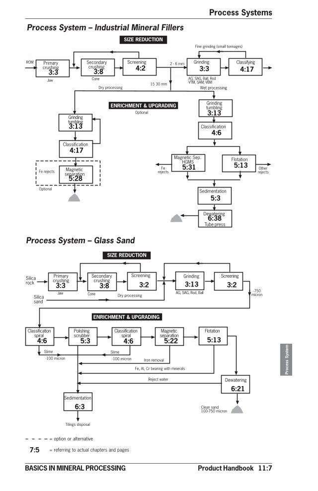
Product Handbook 11:7
Process Systems
Proc
ess
Syst
em
BASICS IN MINERAL PROCESSING
��������;
��������������
���������������
�������� ������� ��������
������� ����--��
������������
���� ���������������
��� 3�4��3�4���4�5��������������
=��'>&*
�����
��������
�������������������
�������������������
�� ��������������
�������
����������
�����
������������
'#**������ 1������,��
��4�3�4����-����� ��������������
��7���������
�����
'#**������
����� ���������
����������#**'>&*������
Process System – Industrial Mineral Fillers
Process System – Glass Sand
��� ��������������
���������������
�������� ������� ����������
�������
������� ���-���
������� ���-���
�������������
�� ��������������
����7����
������������
���� ���������������
��� 3�4��3�4�5���4���<��4��3�?�<5�
�����������
=��
�����7����
�������������
�������
�� ���������28���
�������7����
������������
������������
��������
.�'�(���
#&�%*���
����� ������ � ���������� ��"
�������
3:3 3:8 3:34:2
3:13
4:17
3:13
4:17
5:28
4:6
5:31 5:13
5:3
6:38Tube press
= option or alternative
= referring to actual chapters and pages7:5
3:3 3:8 3:133:2 3:2
4:6 5:3 5:224:6 5:13
6:21
6:3
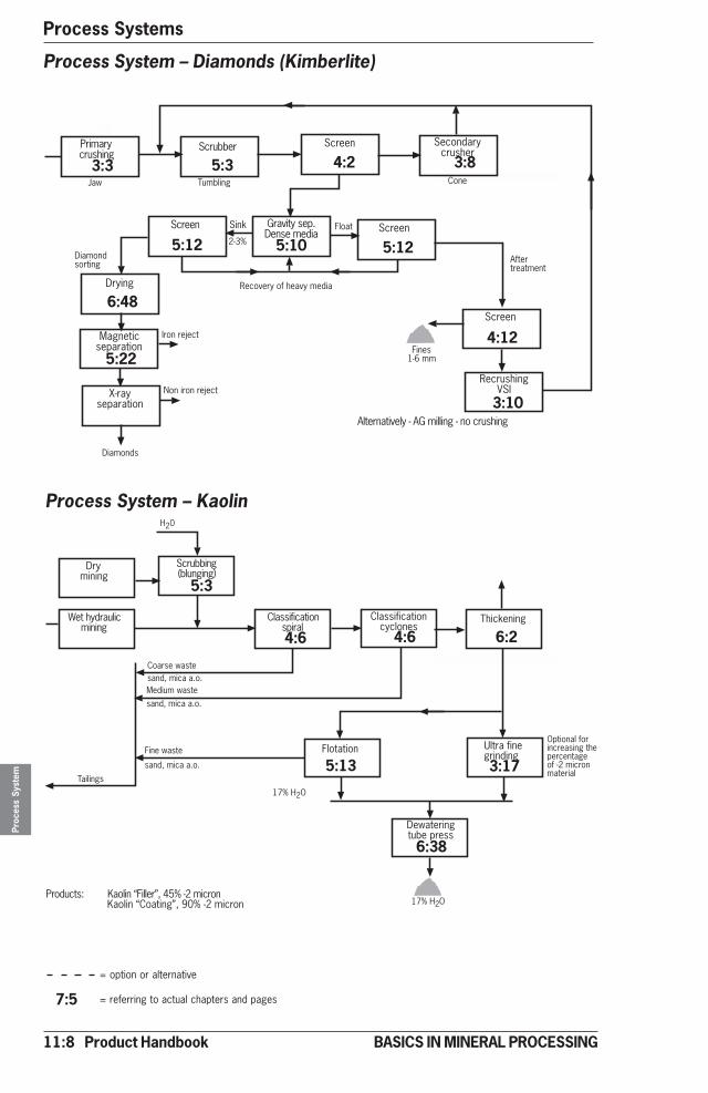
11:8 Product Handbook
Process SystemsPr
oces
s Sy
stem
BASICS IN MINERAL PROCESSING
����--�� ������ ���������������
���������,�������2����������
�� ��������������
������
��������� <�1
���;
���
.'%@
�����#'(���
=��
A��������7���
1�����7���
B'������������
������
����������
��������������
���-���
������ ����
���� ���,���������,�������
3�������������
3��������,����'�3�������� �'����������
Process System – Diamonds (Kimberlite)
Process System – Kaolin
������������������
������������������� ������������ ���'.��������������
�������C D�����E������F4�)&@�'.������D�����E����� F4�G*@�'.������
8.*
����--�� -��� �� "
�������
������ �
����������
����4�������22
#>@�8.�
���������������4�������22������������
����4�������22
������� H��������� ������
�������������������
��������������������
����;����
�������� ��-�������
#>@�8.�
= option or alternative
= referring to actual chapters and pages7:5
3:3 5:3 3:84:2
5:12 5:10 5:12
6:48
5:224:12
3:10
5:3
4:6 4:6 6:2
5:13 3:17
6:38
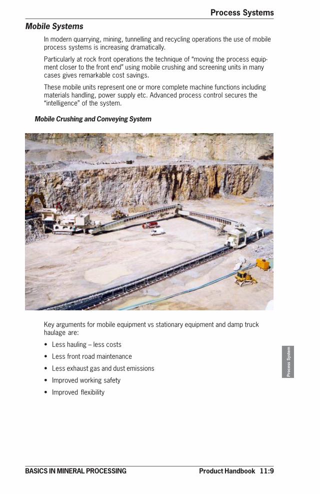
Product Handbook 11:9
Process Systems
Proc
ess
Syst
em
BASICS IN MINERAL PROCESSING
Mobile SystemsIn modern quarrying, mining, tunnelling and recycling operations the use of mobileprocess systems is increasing dramatically.
Particularly at rock front operations the technique of “moving the process equip-ment closer to the front end” using mobile crushing and screening units in manycases gives remarkable cost savings.
These mobile units represent one or more complete machine functions includingmaterials handling, power supply etc. Advanced process control secures the“intelligence” of the system.
Mobile Crushing and Conveying System
Key arguments for mobile equipment vs stationary equipment and damp truckhaulage are:
• Less hauling – less costs
• Less front road maintenance
• Less exhaust gas and dust emissions
• Improved working safety
• Improved flexibility

11:10 Product Handbook
Process SystemsPr
oces
s Sy
stem
BASICS IN MINERAL PROCESSING
Type* Max feed/product size Cap. tph H/W/L m (ft) Weight tonmm (in)
LT110 670 / 250 (26/10) 700 4.4/3.0/17.4 (14.5/9.1/57.0) 60 LT125 800 / 300 (31/12) 800 5.7/4.0/15.8(18.6/15.2/51.1) 86 LT140 900 / 350 (35/14) 1200 6.3/4.3/16.4(20.8/14.1/53.1) 110 LT160 1040/ 400 (41/16) 2000 7.6/5.9/20.2(25.0/19.3/66.7) 220
*LT110 refers to Jaw crusher type C110, LT125 to Jaw crusher type C125 etc. see further section 3.
Primary Impact Crusher + Grizzly (typical)
Type* Max feed/product size Cap. thp H/W/L m (ft) Weight ton mm (in)
LT1415 1000/200 (40/8) 800 5.4/4.0/15.8 (17.7/13.1/51.1) 73LT1620 1300/200 (52/8) 1200 6.5/4.8/18.5 (21.3/15.7/60.7) 170
*LT 1415 refers to Impact crusher type NP1415, LT 1620 to Impact crusher type NP1620 etc. see further
section 3.
Primary Jaw Crusher + Grizzly (typical)
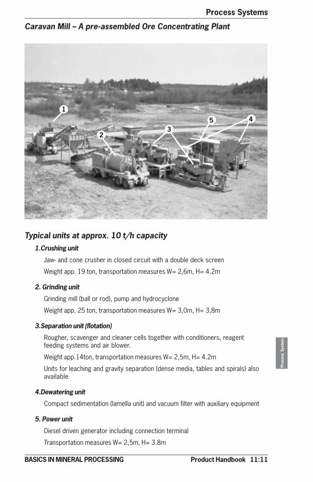
Product Handbook 11:11
Process Systems
Proc
ess
Syst
em
BASICS IN MINERAL PROCESSING
Caravan Mill – A pre-assembled Ore Concentrating Plant
1.Crushing unit
Jaw- and cone crusher in closed circuit with a double deck screen
Weight app. 19 ton, transportation measures W= 2,6m, H= 4.2m
2. Grinding unit
Grinding mill (ball or rod), pump and hydrocyclone
Weight app. 25 ton, transportation measures W= 3,0m, H= 3,8m
3.Separation unit (flotation)
Rougher, scavenger and cleaner cells together with conditioners, reagentfeeding systems and air blower.
Weight app.14ton, transportation measures W= 2,5m, H= 4.2m
Units for leaching and gravity separation (dense media, tables and spirals) alsoavailable
4.Dewatering unit
Compact sedimentation (lamella unit) and vacuum filter with auxiliary equipment
5. Power unit
Diesel driven generator including connection terminal
Transportation measures W= 2,5m, H= 3.8m
Typical units at approx. 10 t/h capacity
1
23
45
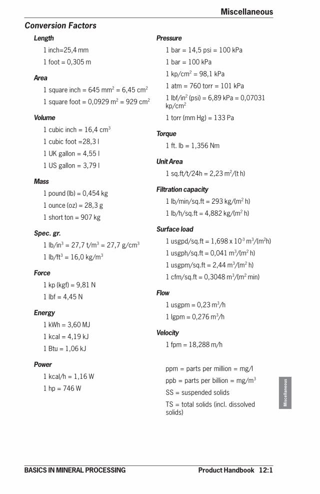
Product Handbook 12:1
Miscellaneous
Mis
cella
neou
s
BASICS IN MINERAL PROCESSING
Conversion FactorsLength
1 inch=25,4 mm
1 foot = 0,305 m
Area
1 square inch = 645 mm2 = 6,45 cm2
1 square foot = 0,0929 m2 = 929 cm2
Volume
1 cubic inch = 16,4 cm3
1 cubic foot =28,3 l
1 UK gallon = 4,55 l
1 US gallon = 3,79 l
Mass
1 pound (lb) = 0,454 kg
1 ounce (oz) = 28,3 g
1 short ton = 907 kg
Spec. gr.
1 lb/in3 = 27,7 t/m3 = 27,7 g/cm3
1 lb/ft3 = 16,0 kg/m3
Force
1 kp (kgf) = 9,81 N
1 lbf = 4,45 N
Energy
1 kWh = 3,60 MJ
1 kcal = 4,19 kJ
1 Btu = 1,06 kJ
Power
1 kcal/h = 1,16 W
1 hp = 746 W
Pressure
1 bar = 14,5 psi = 100 kPa
1 bar = 100 kPa
1 kp/cm2 = 98,1 kPa
1 atm = 760 torr = 101 kPa
1 lbf/in2 (psi) = 6,89 kPa = 0,07031kp/cm2
1 torr (mm Hg) = 133 Pa
Torque
1 ft. lb = 1,356 Nm
Unit Area
1 sq.ft/t/24h = 2,23 m2/(t h)
Filtration capacity
1 lb/min/sq.ft = 293 kg/(m2 h)
1 lb/h/sq.ft = 4,882 kg/(m2 h)
Surface load
1 usgpd/sq.ft = 1,698 x 10-3 m3/(m2h)
1 usgph/sq.ft = 0,041 m3/(m2 h)
1 usgpm/sq.ft = 2,44 m3/(m2 h)
1 cfm/sq.ft = 0,3048 m3/(m2 min)
Flow
1 usgpm = 0,23 m3/h
1 Igpm = 0,276 m3/h
Velocity
1 fpm = 18,288 m/h
ppm = parts per million = mg/l
ppb = parts per billion = mg/m3
SS = suspended solids
TS = total solids (incl. dissolvedsolids)
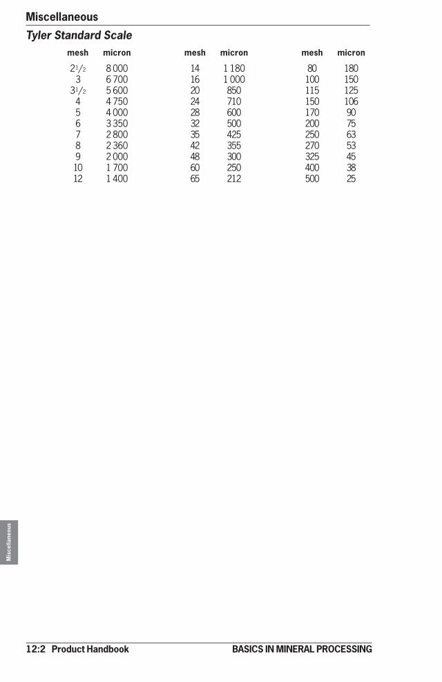
12:2 Product Handbook
MiscellaneousM
isce
llane
ous
BASICS IN MINERAL PROCESSING
Tyler Standard Scalemesh micron mesh micron mesh micron
21/2 8 000 14 1 180 80 1803 6 700 16 1 000 100 150
31/2 5 600 20 850 115 1254 4 750 24 710 150 1065 4 000 28 600 170 906 3 350 32 500 200 757 2 800 35 425 250 638 2 360 42 355 270 539 2 000 48 300 325 4510 1 700 60 250 400 3812 1 400 65 212 500 25

Product Handbook 12:3
Miscellaneous
Mis
cella
neou
s
BASICS IN MINERAL PROCESSING
Density of SolidsMineral Density Mineral Density
AAlbite 2,6Almandine 4,3Anatase 3,9Andradite 3,8Apatite 3,2Arsenopyrite 5,9-6,2Asbestos 2,4-2,5Azurite 3,8
BBaddeleyite 5,6Barite 4,5Bauxite 2,6Beryl 2,7-2,8Biotite 3,0-3,1Bismuth 9,8
CCalcite 2,7Cassiterite 7,0Celestite 4,0Cerussite 6,6Chalcocite 5,5-5,8Chalcopyrite 4,1-4,3Chlorite 2,6-3,2Chromite 5,1Crysocolla 2,0-2,3Cinnabar 8,1Cobaltite 6,0-6,3Coemanite 2,4Copper 8,9Corundum 3,9-4,1Covellite 4,7Cryolite 3,0Cuprite 5,8-6,2
DDiamond 3,5Diopside 3,3-3,4Dolomite 1,8-2,9
EEpidote 3,4
FFeldspar Group 2,6-2,8Ferberite 7,5Flint 2,6Fluorite 3,2Franklinite 5,1-5,2
GGahnite 4,6Galena 7,5Goethite 4,3Gold 15,6-19,3Graphite 2,1-2,2Grossularite 3,5Gypsum 2,3
HHalite 2,5Hematite 5,2Hornblende 3,1-3,3Huebnerite 6,7-7,5Hypersthene 3,4
IIlmenite 4,7
KKaolinite 2,6Kyanite 3,6-3,7
LLepidolite 2,8-2,9Limonite 2,2-2,4
MMagnesite 3,0Magnetite 4,7Malachite 4,0Magnite 4,3Marcasite 4,6-4,9Martite 5,2Microline 2,6Microlite 5,5Molybdenite 4,7-5,0Monazite 4,9-5,5Mullite 3,2Muscovite 2,8-3,0
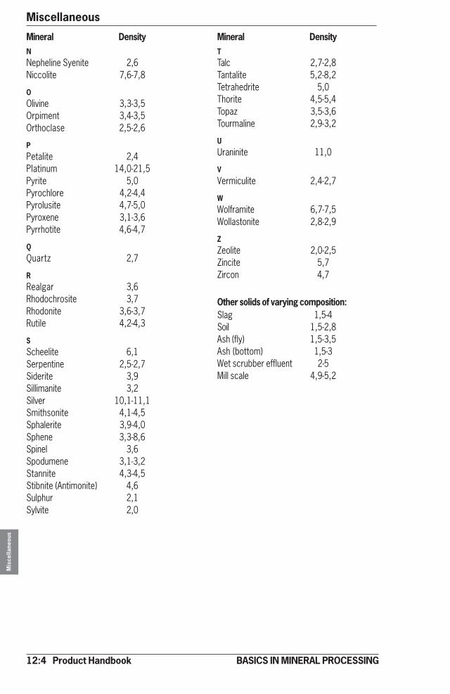
12:4 Product Handbook
MiscellaneousM
isce
llane
ous
BASICS IN MINERAL PROCESSING
Mineral Density Mineral DensityNNepheline Syenite 2,6Niccolite 7,6-7,8
OOlivine 3,3-3,5Orpiment 3,4-3,5Orthoclase 2,5-2,6
PPetalite 2,4Platinum 14,0-21,5Pyrite 5,0Pyrochlore 4,2-4,4Pyrolusite 4,7-5,0Pyroxene 3,1-3,6Pyrrhotite 4,6-4,7
QQuartz 2,7
RRealgar 3,6Rhodochrosite 3,7Rhodonite 3,6-3,7Rutile 4,2-4,3
SScheelite 6,1Serpentine 2,5-2,7Siderite 3,9Sillimanite 3,2Silver 10,1-11,1Smithsonite 4,1-4,5Sphalerite 3,9-4,0Sphene 3,3-8,6Spinel 3,6Spodumene 3,1-3,2Stannite 4,3-4,5Stibnite (Antimonite) 4,6Sulphur 2,1Sylvite 2,0
TTalc 2,7-2,8Tantalite 5,2-8,2Tetrahedrite 5,0Thorite 4,5-5,4Topaz 3,5-3,6Tourmaline 2,9-3,2
UUraninite 11,0
VVermiculite 2,4-2,7
WWolframite 6,7-7,5Wollastonite 2,8-2,9
ZZeolite 2,0-2,5Zincite 5,7Zircon 4,7
Other solids of varying composition:Slag 1,5-4Soil 1,5-2,8Ash (fly) 1,5-3,5Ash (bottom) 1,5-3Wet scrubber effluent 2-5Mill scale 4,9-5,2
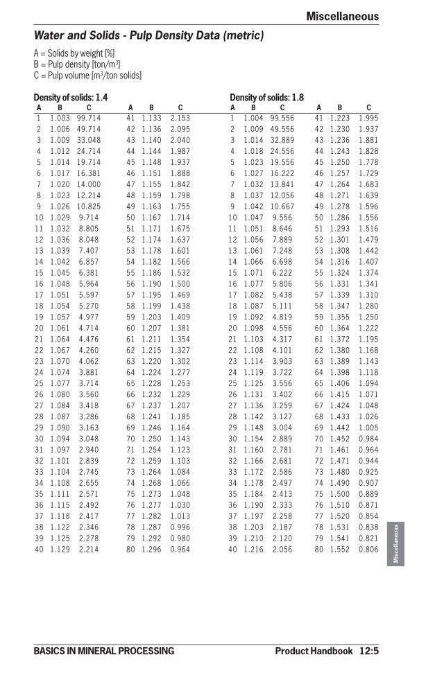
Product Handbook 12:5
Miscellaneous
Mis
cella
neou
s
BASICS IN MINERAL PROCESSING
Water and Solids - Pulp Density Data (metric)A = Solids by weight [%]B = Pulp density [ton/m3]C = Pulp volume [m3/ton solids]
Density of solids: 1.4 Density of solids: 1.8A B C A B C A B C A B C1 1.003 99.714 41 1.133 2.153 1 1.004 99.556 41 1.223 1.9952 1.006 49.714 42 1.136 2.095 2 1.009 49.556 42 1.230 1.9373 1.009 33.048 43 1.140 2.040 3 1.014 32.889 43 1.236 1.8814 1.012 24.714 44 1.144 1.987 4 1.018 24.556 44 1.243 1.8285 1.014 19.714 45 1.148 1.937 5 1.023 19.556 45 1.250 1.7786 1.017 16.381 46 1.151 1.888 6 1.027 16.222 46 1.257 1.7297 1.020 14.000 47 1.155 1.842 7 1.032 13.841 47 1.264 1.6838 1.023 12.214 48 1.159 1.798 8 1.037 12.056 48 1.271 1.6399 1.026 10.825 49 1.163 1.755 9 1.042 10.667 49 1.278 1.596
10 1.029 9.714 50 1.167 1.714 10 1.047 9.556 50 1.286 1.55611 1.032 8.805 51 1.171 1.675 11 1.051 8.646 51 1.293 1.51612 1.036 8.048 52 1.174 1.637 12 1.056 7.889 52 1.301 1.47913 1.039 7.407 53 1.178 1.601 13 1.061 7.248 53 1.308 1.44214 1.042 6.857 54 1.182 1.566 14 1.066 6.698 54 1.316 1.40715 1.045 6.381 55 1.186 1.532 15 1.071 6.222 55 1.324 1.37416 1.048 5.964 56 1.190 1.500 16 1.077 5.806 56 1.331 1.34117 1.051 5.597 57 1.195 1.469 17 1.082 5.438 57 1.339 1.31018 1.054 5.270 58 1.199 1.438 18 1.087 5.111 58 1.347 1.28019 1.057 4.977 59 1.203 1.409 19 1.092 4.819 59 1.355 1.25020 1.061 4.714 60 1.207 1.381 20 1.098 4.556 60 1.364 1.22221 1.064 4.476 61 1.211 1.354 21 1.103 4.317 61 1.372 1.19522 1.067 4.260 62 1.215 1.327 22 1.108 4.101 62 1.380 1.16823 1.070 4.062 63 1.220 1.302 23 1.114 3.903 63 1.389 1.14324 1.074 3.881 64 1.224 1.277 24 1.119 3.722 64 1.398 1.11825 1.077 3.714 65 1.228 1.253 25 1.125 3.556 65 1.406 1.09426 1.080 3.560 66 1.232 1.229 26 1.131 3.402 66 1.415 1.07127 1.084 3.418 67 1.237 1.207 27 1.136 3.259 67 1.424 1.04828 1.087 3.286 68 1.241 1.185 28 1.142 3.127 68 1.433 1.02629 1.090 3.163 69 1.246 1.164 29 1.148 3.004 69 1.442 1.00530 1.094 3.048 70 1.250 1.143 30 1.154 2.889 70 1.452 0.98431 1.097 2.940 71 1.254 1.123 31 1.160 2.781 71 1.461 0.96432 1.101 2.839 72 1.259 1.103 32 1.166 2.681 72 1.471 0.94433 1.104 2.745 73 1.264 1.084 33 1.172 2.586 73 1.480 0.92534 1.108 2.655 74 1.268 1.066 34 1.178 2.497 74 1.490 0.90735 1.111 2.571 75 1.273 1.048 35 1.184 2.413 75 1.500 0.88936 1.115 2.492 76 1.277 1.030 36 1.190 2.333 76 1.510 0.87137 1.118 2.417 77 1.282 1.013 37 1.197 2.258 77 1.520 0.85438 1.122 2.346 78 1.287 0.996 38 1.203 2.187 78 1.531 0.83839 1.125 2.278 79 1.292 0.980 39 1.210 2.120 79 1.541 0.82140 1.129 2.214 80 1.296 0.964 40 1.216 2.056 80 1.552 0.806

12:6 Product Handbook
MiscellaneousM
isce
llane
ous
BASICS IN MINERAL PROCESSING
Water and Solids - Pulp Density Data (US)A = Solids by weight [%]B = Pulp densityC = Pulp volume [USG/ston solids]
Density of solids: 1.4 Density of solids: 1.8A B C A B C A B C A B C1 1.003 23897 41 1.133 516 1 1.004 23859 41 1.223 4782 1.006 11914 42 1.136 502 2 1.009 11876 42 1.230 4643 1.009 7920 43 1.140 489 3 1.014 7882 43 1.236 4514 1.012 5923 44 1.144 476 4 1.018 5885 44 1.243 4385 1.014 4725 45 1.148 464 5 1.023 4687 45 1.250 4266 1.017 3926 46 1.151 452 6 1.027 3888 46 1.257 4147 1.020 3355 47 1.155 441 7 1.032 3317 47 1.264 4038 1.023 2927 48 1.159 431 8 1.037 2889 48 1.271 3939 1.026 2594 49 1.163 421 9 1.042 2556 49 1.278 382
10 1.029 2328 50 1.167 411 10 1.047 2290 50 1.286 37311 1.032 2110 51 1.171 401 11 1.051 2072 51 1.293 36312 1.036 1929 52 1.174 392 12 1.056 1891 52 1.301 35413 1.039 1775 53 1.178 384 13 1.061 1737 53 1.308 34614 1.042 1643 54 1.182 375 14 1.066 1605 54 1.316 33715 1.045 1529 55 1.186 367 15 1.071 1491 55 1.324 32916 1.048 1429 56 1.190 359 16 1.077 1391 56 1.331 32117 1.051 1341 57 1.195 352 17 1.082 1303 57 1.339 31418 1.054 1263 58 1.199 345 18 1.087 1225 58 1.347 30719 1.057 1193 59 1.203 338 19 1.092 1155 59 1.355 30020 1.061 1130 60 1.207 331 20 1.098 1092 60 1.364 29321 1.064 1073 61 1.211 324 21 1.103 1035 61 1.372 28622 1.067 1021 62 1.215 318 22 1.108 983 62 1.380 28023 1.070 973 63 1.220 312 23 1.114 935 63 1.389 27424 1.074 930 64 1.224 306 24 1.119 892 64 1.398 26825 1.077 890 65 1.228 300 25 1.125 852 65 1.406 26226 1.080 853 66 1.232 295 26 1.131 815 66 1.415 25727 1.084 819 67 1.237 289 27 1.136 781 67 1.424 25128 1.087 787 68 1.241 284 28 1.142 749 68 1.433 24629 1.090 758 69 1.246 279 29 1.148 720 69 1.442 24130 1.094 730 70 1.250 274 30 1.154 692 70 1.452 23631 1.097 705 71 1.254 269 31 1.160 666 71 1.461 23132 1.101 680 72 1.259 264 32 1.166 643 72 1.471 22633 1.104 658 73 1.264 260 33 1.172 620 73 1.480 22234 1.108 636 74 1.268 255 34 1.178 598 74 1.490 21735 1.111 616 75 1.273 251 35 1.184 578 75 1.500 21336 1.115 597 76 1.277 247 36 1.190 559 76 1.510 20937 1.118 579 77 1.282 243 37 1.197 541 77 1.520 20538 1.122 562 78 1.287 239 38 1.203 524 78 1.531 20139 1.125 546 79 1.292 235 39 1.210 508 79 1.541 19740 1.129 531 80 1.296 231 40 1.216 493 80 1.552 193
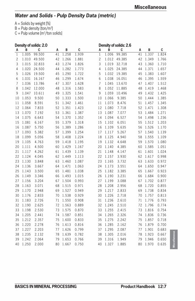
Product Handbook 12:7
Miscellaneous
Mis
cella
neou
s
BASICS IN MINERAL PROCESSING
Water and Solids - Pulp Density Data (metric)A = Solids by weight [%]B = Pulp density [ton/m3]C = Pulp volume [m3/ton solids]
Density of solids: 2.0 Density of solids: 2.6A B C A B C A B C A B C1 1.005 99.500 41 1.258 1.939 1 1.006 99.385 41 1.337 1.8242 1.010 49.500 42 1.266 1.881 2 1.012 49.385 42 1.349 1.7663 1.015 32.833 43 1.274 1.826 3 1.019 32.718 43 1.360 1.7104 1.020 24.500 44 1.282 1.773 4 1.025 24.385 44 1.371 1.6575 1.026 19.500 45 1.290 1.722 5 1.032 19.385 45 1.383 1.6076 1.031 16.167 46 1.299 1.674 6 1.038 16.051 46 1.395 1.5597 1.036 13.786 47 1.307 1.628 7 1.045 13.670 47 1.407 1.5128 1.042 12.000 48 1.316 1.583 8 1.052 11.885 48 1.419 1.4689 1.047 10.611 49 1.325 1.541 9 1.059 10.496 49 1.432 1.425
10 1.053 9.500 50 1.333 1.500 10 1.066 9.385 50 1.444 1.38511 1.058 8.591 51 1.342 1.461 11 1.073 8.476 51 1.457 1.34512 1.064 7.833 52 1.351 1.423 12 1.080 7.718 52 1.471 1.30813 1.070 7.192 53 1.361 1.387 13 1.087 7.077 53 1.484 1.27114 1.075 6.643 54 1.370 1.352 14 1.094 6.527 54 1.498 1.23615 1.081 6.167 55 1.379 1.318 15 1.102 6.051 55 1.512 1.20316 1.087 5.750 56 1.389 1.286 16 1.109 5.635 56 1.526 1.17017 1.093 5.382 57 1.399 1.254 17 1.117 5.267 57 1.540 1.13918 1.099 5.056 58 1.408 1.224 18 1.125 4.940 58 1.555 1.10919 1.105 4.763 59 1.418 1.195 19 1.132 4.648 59 1.570 1.08020 1.111 4.500 60 1.429 1.167 20 1.140 4.385 60 1.585 1.05121 1.117 4.262 61 1.439 1.139 21 1.148 4.147 61 1.601 1.02422 1.124 4.045 62 1.449 1.113 22 1.157 3.930 62 1.617 0.99823 1.130 3.848 63 1.460 1.087 23 1.165 3.732 63 1.633 0.97224 1.136 3.667 64 1.471 1.063 24 1.173 3.551 64 1.650 0.94725 1.143 3.500 65 1.481 1.038 25 1.182 3.385 65 1.667 0.92326 1.149 3.346 66 1.493 1.015 26 1.190 3.231 66 1.684 0.90027 1.156 3.204 67 1.504 0.993 27 1.199 3.088 67 1.702 0.87728 1.163 3.071 68 1.515 0.971 28 1.208 2.956 68 1.720 0.85529 1.170 2.948 69 1.527 0.949 29 1.217 2.833 69 1.738 0.83430 1.176 2.833 70 1.538 0.929 30 1.226 2.718 70 1.757 0.81331 1.183 2.726 71 1.550 0.908 31 1.236 2.610 71 1.776 0.79332 1.190 2.625 72 1.563 0.889 32 1.245 2.510 72 1.796 0.77433 1.198 2.530 73 1.575 0.870 33 1.255 2.415 73 1.816 0.75434 1.205 2.441 74 1.587 0.851 34 1.265 2.326 74 1.836 0.73635 1.212 2.357 75 1.600 0.833 35 1.275 2.242 75 1.857 0.71836 1.220 2.278 76 1.613 0.816 36 1.285 2.162 76 1.879 0.70037 1.227 2.203 77 1.626 0.799 37 1.295 2.087 77 1.901 0.68338 1.235 2.132 78 1.639 0.782 38 1.305 2.016 78 1.923 0.66739 1.242 2.064 79 1.653 0.766 39 1.316 1.949 79 1.946 0.65040 1.250 2.000 80 1.667 0.750 40 1.327 1.885 80 1.970 0.635

12:8 Product Handbook
MiscellaneousM
isce
llane
ous
BASICS IN MINERAL PROCESSING
Water and Solids - Pulp Density Data (US)A = Solids by weight [%]B = Pulp densityC = Pulp volume [USG/ston solids]
Density of solids: 2.0 Density of solids: 2.6A B C A B C A B C A B C1 1.005 23845 41 1.258 465 1 1.006 23818 41 1.337 4372 1.010 11863 42 1.266 451 2 1.012 11835 42 1.349 4233 1.015 7869 43 1.274 438 3 1.019 7841 43 1.360 4104 1.020 5871 44 1.282 425 4 1.025 5844 44 1.371 3975 1.026 4673 45 1.290 413 5 1.032 4646 45 1.383 3856 1.031 3874 46 1.299 401 6 1.038 3847 46 1.395 3747 1.036 3304 47 1.307 390 7 1.045 3276 47 1.407 3628 1.042 2876 48 1.316 379 8 1.052 2848 48 1.419 3529 1.047 2543 49 1.325 369 9 1.059 2515 49 1.432 342
10 1.053 2277 50 1.333 359 10 1.066 2249 50 1.444 33211 1.058 2059 51 1.342 350 11 1.073 2031 51 1.457 32212 1.064 1877 52 1.351 341 12 1.080 1850 52 1.471 31313 1.070 1724 53 1.361 332 13 1.087 1696 53 1.484 30514 1.075 1592 54 1.370 324 14 1.094 1564 54 1.498 29615 1.081 1478 55 1.379 316 15 1.102 1450 55 1.512 28816 1.087 1378 56 1.389 308 16 1.109 1350 56 1.526 28017 1.093 1290 57 1.399 301 17 1.117 1262 57 1.540 27318 1.099 1212 58 1.408 293 18 1.125 1184 58 1.555 26619 1.105 1141 59 1.418 286 19 1.132 1114 59 1.570 25920 1.111 1078 60 1.429 280 20 1.140 1051 60 1.585 25221 1.117 1021 61 1.439 273 21 1.148 994 61 1.601 24522 1.124 969 62 1.449 267 22 1.157 942 62 1.617 23923 1.130 922 63 1.460 261 23 1.165 894 63 1.633 23324 1.136 879 64 1.471 255 24 1.173 851 64 1.650 22725 1.143 839 65 1.481 249 25 1.182 811 65 1.667 22126 1.149 802 66 1.493 243 26 1.190 774 66 1.684 21627 1.156 768 67 1.504 238 27 1.199 740 67 1.702 21028 1.163 736 68 1.515 233 28 1.208 708 68 1.720 20529 1.170 706 69 1.527 227 29 1.217 679 69 1.738 20030 1.176 679 70 1.538 223 30 1.226 651 70 1.757 19531 1.183 653 71 1.550 218 31 1.236 625 71 1.776 19032 1.190 629 72 1.563 213 32 1.245 602 72 1.796 18533 1.198 606 73 1.575 208 33 1.255 579 73 1.816 18134 1.205 585 74 1.587 204 34 1.265 557 74 1.836 17635 1.212 565 75 1.600 200 35 1.275 537 75 1.857 17236 1.220 546 76 1.613 196 36 1.285 518 76 1.879 16837 1.227 528 77 1.626 191 37 1.295 500 77 1.901 16438 1.235 511 78 1.639 187 38 1.305 483 78 1.923 16039 1.242 495 79 1.653 184 39 1.316 467 79 1.946 15640 1.250 479 80 1.667 180 40 1.327 452 80 1.970 152
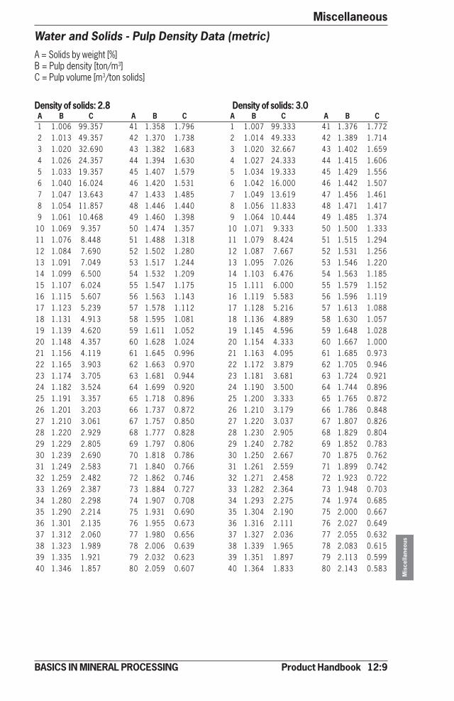
Product Handbook 12:9
Miscellaneous
Mis
cella
neou
s
BASICS IN MINERAL PROCESSING
Water and Solids - Pulp Density Data (metric)A = Solids by weight [%]B = Pulp density [ton/m3]C = Pulp volume [m3/ton solids]
Density of solids: 2.8 Density of solids: 3.0A B C A B C A B C A B C1 1.006 99.357 41 1.358 1.796 1 1.007 99.333 41 1.376 1.7722 1.013 49.357 42 1.370 1.738 2 1.014 49.333 42 1.389 1.7143 1.020 32.690 43 1.382 1.683 3 1.020 32.667 43 1.402 1.6594 1.026 24.357 44 1.394 1.630 4 1.027 24.333 44 1.415 1.6065 1.033 19.357 45 1.407 1.579 5 1.034 19.333 45 1.429 1.5566 1.040 16.024 46 1.420 1.531 6 1.042 16.000 46 1.442 1.5077 1.047 13.643 47 1.433 1.485 7 1.049 13.619 47 1.456 1.4618 1.054 11.857 48 1.446 1.440 8 1.056 11.833 48 1.471 1.4179 1.061 10.468 49 1.460 1.398 9 1.064 10.444 49 1.485 1.374
10 1.069 9.357 50 1.474 1.357 10 1.071 9.333 50 1.500 1.33311 1.076 8.448 51 1.488 1.318 11 1.079 8.424 51 1.515 1.29412 1.084 7.690 52 1.502 1.280 12 1.087 7.667 52 1.531 1.25613 1.091 7.049 53 1.517 1.244 13 1.095 7.026 53 1.546 1.22014 1.099 6.500 54 1.532 1.209 14 1.103 6.476 54 1.563 1.18515 1.107 6.024 55 1.547 1.175 15 1.111 6.000 55 1.579 1.15216 1.115 5.607 56 1.563 1.143 16 1.119 5.583 56 1.596 1.11917 1.123 5.239 57 1.578 1.112 17 1.128 5.216 57 1.613 1.08818 1.131 4.913 58 1.595 1.081 18 1.136 4.889 58 1.630 1.05719 1.139 4.620 59 1.611 1.052 19 1.145 4.596 59 1.648 1.02820 1.148 4.357 60 1.628 1.024 20 1.154 4.333 60 1.667 1.00021 1.156 4.119 61 1.645 0.996 21 1.163 4.095 61 1.685 0.97322 1.165 3.903 62 1.663 0.970 22 1.172 3.879 62 1.705 0.94623 1.174 3.705 63 1.681 0.944 23 1.181 3.681 63 1.724 0.92124 1.182 3.524 64 1.699 0.920 24 1.190 3.500 64 1.744 0.89625 1.191 3.357 65 1.718 0.896 25 1.200 3.333 65 1.765 0.87226 1.201 3.203 66 1.737 0.872 26 1.210 3.179 66 1.786 0.84827 1.210 3.061 67 1.757 0.850 27 1.220 3.037 67 1.807 0.82628 1.220 2.929 68 1.777 0.828 28 1.230 2.905 68 1.829 0.80429 1.229 2.805 69 1.797 0.806 29 1.240 2.782 69 1.852 0.78330 1.239 2.690 70 1.818 0.786 30 1.250 2.667 70 1.875 0.76231 1.249 2.583 71 1.840 0.766 31 1.261 2.559 71 1.899 0.74232 1.259 2.482 72 1.862 0.746 32 1.271 2.458 72 1.923 0.72233 1.269 2.387 73 1.884 0.727 33 1.282 2.364 73 1.948 0.70334 1.280 2.298 74 1.907 0.708 34 1.293 2.275 74 1.974 0.68535 1.290 2.214 75 1.931 0.690 35 1.304 2.190 75 2.000 0.66736 1.301 2.135 76 1.955 0.673 36 1.316 2.111 76 2.027 0.64937 1.312 2.060 77 1.980 0.656 37 1.327 2.036 77 2.055 0.63238 1.323 1.989 78 2.006 0.639 38 1.339 1.965 78 2.083 0.61539 1.335 1.921 79 2.032 0.623 39 1.351 1.897 79 2.113 0.59940 1.346 1.857 80 2.059 0.607 40 1.364 1.833 80 2.143 0.583

12:10 Product Handbook
MiscellaneousM
isce
llane
ous
BASICS IN MINERAL PROCESSING
Water and Solids - Pulp Density Data (US)A = Solids by weight [%]B = Pulp densityC = Pulp volume [USG/ston solids]
Density of solids: 2.8 Density of solids: 3.0A B C A B C A B C A B C1 1.006 23811 41 1.358 430 1 1.007 23805 41 1.376 4252 1.013 11829 42 1.370 417 2 1.014 11823 42 1.389 4113 1.020 7834 43 1.382 403 3 1.020 7829 43 1.402 3984 1.026 5837 44 1.394 391 4 1.027 5831 44 1.415 3855 1.033 4639 45 1.407 378 5 1.034 4633 45 1.429 3736 1.040 3840 46 1.420 367 6 1.042 3834 46 1.442 3617 1.047 3270 47 1.433 356 7 1.049 3264 47 1.456 3508 1.054 2842 48 1.446 345 8 1.056 2836 48 1.471 3409 1.061 2509 49 1.460 335 9 1.064 2503 49 1.485 329
10 1.069 2242 50 1.474 325 10 1.071 2237 50 1.500 31911 1.076 2025 51 1.488 316 11 1.079 2019 51 1.515 31012 1.084 1843 52 1.502 307 12 1.087 1837 52 1.531 30113 1.091 1689 53 1.517 298 13 1.095 1684 53 1.546 29214 1.099 1558 54 1.532 290 14 1.103 1552 54 1.563 28415 1.107 1444 55 1.547 282 15 1.111 1438 55 1.579 27616 1.115 1344 56 1.563 274 16 1.119 1338 56 1.596 26817 1.123 1256 57 1.578 266 17 1.128 1250 57 1.613 26118 1.131 1177 58 1.595 259 18 1.136 1172 58 1.630 25319 1.139 1107 59 1.611 252 19 1.145 1101 59 1.648 24620 1.148 1044 60 1.628 245 20 1.154 1038 60 1.667 24021 1.156 987 61 1.645 239 21 1.163 981 61 1.685 23322 1.165 935 62 1.663 232 22 1.172 930 62 1.705 22723 1.174 888 63 1.681 226 23 1.181 882 63 1.724 22124 1.182 845 64 1.699 220 24 1.190 839 64 1.744 21525 1.191 805 65 1.718 215 25 1.200 799 65 1.765 20926 1.201 768 66 1.737 209 26 1.210 762 66 1.786 20327 1.210 734 67 1.757 204 27 1.220 728 67 1.807 19828 1.220 702 68 1.777 198 28 1.230 696 68 1.829 19329 1.229 672 69 1.797 193 29 1.240 667 69 1.852 18830 1.239 645 70 1.818 188 30 1.250 639 70 1.875 18331 1.249 619 71 1.840 184 31 1.261 613 71 1.899 17832 1.259 595 72 1.862 179 32 1.271 589 72 1.923 17333 1.269 572 73 1.884 174 33 1.282 567 73 1.948 16834 1.280 551 74 1.907 170 34 1.293 545 74 1.974 16435 1.290 531 75 1.931 165 35 1.304 525 75 2.000 16036 1.301 512 76 1.955 161 36 1.316 506 76 2.027 15637 1.312 494 77 1.980 157 37 1.327 488 77 2.055 15138 1.323 477 78 2.006 153 38 1.339 471 78 2.083 14739 1.335 460 79 2.032 149 39 1.351 455 79 2.113 14440 1.346 445 80 2.059 145 40 1.364 439 80 2.143 140

Product Handbook 12:11
Miscellaneous
Mis
cella
neou
s
BASICS IN MINERAL PROCESSING
Water and Solids - Pulp Density Data (metric)A = Solids by weight [%]B = Pulp density [ton/m3]C = Pulp volume [m3/ton solids]
Density of solids: 3.2 Density of solids: 3.4A B C A B C A B C A B C1 1.007 99.313 41 1.393 1.752 1 1.007 99.294 41 1.407 1.7332 1.014 49.313 42 1.406 1.693 2 1.014 49.294 42 1.421 1.6753 1.021 32.646 43 1.420 1.638 3 1.022 32.627 43 1.436 1.6204 1.028 24.313 44 1.434 1.585 4 1.029 24.294 44 1.451 1.5675 1.036 19.313 45 1.448 1.535 5 1.037 19.294 45 1.466 1.5166 1.043 15.979 46 1.463 1.486 6 1.044 15.961 46 1.481 1.4687 1.051 13.598 47 1.477 1.440 7 1.052 13.580 47 1.496 1.4228 1.058 11.813 48 1.493 1.396 8 1.060 11.794 48 1.512 1.3779 1.066 10.424 49 1.508 1.353 9 1.068 10.405 49 1.529 1.335
10 1.074 9.313 50 1.524 1.313 10 1.076 9.294 50 1.545 1.29411 1.082 8.403 51 1.540 1.273 11 1.084 8.385 51 1.563 1.25512 1.090 7.646 52 1.556 1.236 12 1.093 7.627 52 1.580 1.21713 1.098 7.005 53 1.573 1.199 13 1.101 6.986 53 1.598 1.18114 1.107 6.455 54 1.590 1.164 14 1.110 6.437 54 1.616 1.14615 1.115 5.979 55 1.608 1.131 15 1.118 5.961 55 1.635 1.11216 1.124 5.563 56 1.626 1.098 16 1.127 5.544 56 1.654 1.08017 1.132 5.195 57 1.644 1.067 17 1.136 5.176 57 1.673 1.04918 1.141 4.868 58 1.663 1.037 18 1.146 4.850 58 1.693 1.01819 1.150 4.576 59 1.682 1.007 19 1.155 4.557 59 1.714 0.98920 1.159 4.313 60 1.702 0.979 20 1.164 4.294 60 1.735 0.96121 1.169 4.074 61 1.722 0.952 21 1.174 4.056 61 1.756 0.93322 1.178 3.858 62 1.743 0.925 22 1.184 3.840 62 1.778 0.90723 1.188 3.660 63 1.764 0.900 23 1.194 3.642 63 1.801 0.88124 1.198 3.479 64 1.786 0.875 24 1.204 3.461 64 1.824 0.85725 1.208 3.313 65 1.808 0.851 25 1.214 3.294 65 1.848 0.83326 1.218 3.159 66 1.831 0.828 26 1.225 3.140 66 1.872 0.80927 1.228 3.016 67 1.854 0.805 27 1.235 2.998 67 1.897 0.78728 1.238 2.884 68 1.878 0.783 28 1.246 2.866 68 1.923 0.76529 1.249 2.761 69 1.902 0.762 29 1.257 2.742 69 1.950 0.74330 1.260 2.646 70 1.928 0.741 30 1.269 2.627 70 1.977 0.72331 1.271 2.538 71 1.954 0.721 31 1.280 2.520 71 2.005 0.70332 1.282 2.438 72 1.980 0.701 32 1.292 2.419 72 2.033 0.68333 1.293 2.343 73 2.008 0.682 33 1.304 2.324 73 2.063 0.66434 1.305 2.254 74 2.036 0.664 34 1.316 2.235 74 2.094 0.64535 1.317 2.170 75 2.065 0.646 35 1.328 2.151 75 2.125 0.62736 1.329 2.090 76 2.094 0.628 36 1.341 2.072 76 2.157 0.61037 1.341 2.015 77 2.125 0.611 37 1.354 1.997 77 2.191 0.59338 1.354 1.944 78 2.156 0.595 38 1.367 1.926 78 2.225 0.57639 1.366 1.877 79 2.189 0.578 39 1.380 1.858 79 2.261 0.56040 1.379 1.813 80 2.222 0.563 40 1.393 1.794 80 2.297 0.544

12:12 Product Handbook
MiscellaneousM
isce
llane
ous
BASICS IN MINERAL PROCESSING
Water and Solids - Pulp Density Data (US)A = Solids by weight [%]B = Pulp densityC = Pulp volume [USG/ston solids]
Density of solids: 3.2 Density of solids: 3.4A B C A B C A B C A B C1 1.007 23801 41 1.393 420 1 1.007 23796 41 1.407 4152 1.014 11818 42 1.406 406 2 1.014 11813 42 1.421 4013 1.021 7824 43 1.420 393 3 1.022 7819 43 1.436 3884 1.028 5827 44 1.434 380 4 1.029 5822 44 1.451 3765 1.036 4628 45 1.448 368 5 1.037 4624 45 1.466 3636 1.043 3829 46 1.463 356 6 1.044 3825 46 1.481 3527 1.051 3259 47 1.477 345 7 1.052 3254 47 1.496 3418 1.058 2831 48 1.493 335 8 1.060 2826 48 1.512 3309 1.066 2498 49 1.508 324 9 1.068 2494 49 1.529 320
10 1.074 2232 50 1.524 315 10 1.076 2227 50 1.545 31011 1.082 2014 51 1.540 305 11 1.084 2009 51 1.563 30112 1.090 1832 52 1.556 296 12 1.093 1828 52 1.580 29213 1.098 1679 53 1.573 287 13 1.101 1674 53 1.598 28314 1.107 1547 54 1.590 279 14 1.110 1543 54 1.616 27515 1.115 1433 55 1.608 271 15 1.118 1429 55 1.635 26616 1.124 1333 56 1.626 263 16 1.127 1329 56 1.654 25917 1.132 1245 57 1.644 256 17 1.136 1240 57 1.673 25118 1.141 1167 58 1.663 249 18 1.146 1162 58 1.693 24419 1.150 1097 59 1.682 241 19 1.155 1092 59 1.714 23720 1.159 1034 60 1.702 235 20 1.164 1029 60 1.735 23021 1.169 976 61 1.722 228 21 1.174 972 61 1.756 22422 1.178 925 62 1.743 222 22 1.184 920 62 1.778 21723 1.188 877 63 1.764 216 23 1.194 873 63 1.801 21124 1.198 834 64 1.786 210 24 1.204 829 64 1.824 20525 1.208 794 65 1.808 204 25 1.214 789 65 1.848 20026 1.218 757 66 1.831 198 26 1.225 753 66 1.872 19427 1.228 723 67 1.854 193 27 1.235 718 67 1.897 18928 1.238 691 68 1.878 188 28 1.246 687 68 1.923 18329 1.249 662 69 1.902 183 29 1.257 657 69 1.950 17830 1.260 634 70 1.928 178 30 1.269 630 70 1.977 17331 1.271 608 71 1.954 173 31 1.280 604 71 2.005 16832 1.282 584 72 1.980 168 32 1.292 580 72 2.033 16433 1.293 562 73 2.008 163 33 1.304 557 73 2.063 15934 1.305 540 74 2.036 159 34 1.316 536 74 2.094 15535 1.317 520 75 2.065 155 35 1.328 515 75 2.125 15036 1.329 501 76 2.094 151 36 1.341 497 76 2.157 14637 1.341 483 77 2.125 146 37 1.354 479 77 2.191 14238 1.354 466 78 2.156 143 38 1.367 462 78 2.225 13839 1.366 450 79 2.189 139 39 1.380 445 79 2.261 13440 1.379 434 80 2.222 135 40 1.393 430 80 2.297 130

Product Handbook 12:13
Miscellaneous
Mis
cella
neou
s
BASICS IN MINERAL PROCESSING
Water and Solids - Pulp Density Data (metric)A = Solids by weight [%]B = Pulp density [ton/m3]C = Pulp volume [m3/ton solids]
Density of solids: 3.6 Density of solids: 3.8A B C A B C A B C A B C1 1.007 99.278 41 1.421 1.717 1 1.007 99.263 41 1.433 1.7022 1.015 49.278 42 1.435 1.659 2 1.015 49.263 42 1.448 1.6443 1.022 32.611 43 1.450 1.603 3 1.023 32.596 43 1.464 1.5894 1.030 24.278 44 1.466 1.551 4 1.030 24.263 44 1.480 1.5365 1.037 19.278 45 1.481 1.500 5 1.038 19.263 45 1.496 1.4856 1.045 15.944 46 1.498 1.452 6 1.046 15.930 46 1.513 1.4377 1.053 13.563 47 1.514 1.405 7 1.054 13.549 47 1.530 1.3918 1.061 11.778 48 1.531 1.361 8 1.063 11.763 48 1.547 1.3469 1.070 10.389 49 1.548 1.319 9 1.071 10.374 49 1.565 1.304
10 1.078 9.278 50 1.565 1.278 10 1.080 9.263 50 1.583 1.26311 1.086 8.369 51 1.583 1.239 11 1.088 8.354 51 1.602 1.22412 1.095 7.611 52 1.601 1.201 12 1.097 7.596 52 1.621 1.18613 1.104 6.970 53 1.620 1.165 13 1.106 6.955 53 1.641 1.15014 1.112 6.421 54 1.639 1.130 14 1.115 6.406 54 1.661 1.11515 1.121 5.944 55 1.659 1.096 15 1.124 5.930 55 1.681 1.08116 1.131 5.528 56 1.679 1.063 16 1.134 5.513 56 1.703 1.04917 1.140 5.160 57 1.700 1.032 17 1.143 5.146 57 1.724 1.01818 1.149 4.833 58 1.721 1.002 18 1.153 4.819 58 1.746 0.98719 1.159 4.541 59 1.742 0.973 19 1.163 4.526 59 1.769 0.95820 1.169 4.278 60 1.765 0.944 20 1.173 4.263 60 1.792 0.93021 1.179 4.040 61 1.787 0.917 21 1.183 4.025 61 1.816 0.90322 1.189 3.823 62 1.811 0.891 22 1.193 3.809 62 1.841 0.87623 1.199 3.626 63 1.835 0.865 23 1.204 3.611 63 1.866 0.85024 1.210 3.444 64 1.860 0.840 24 1.215 3.430 64 1.892 0.82625 1.220 3.278 65 1.885 0.816 25 1.226 3.263 65 1.919 0.80226 1.231 3.124 66 1.911 0.793 26 1.237 3.109 66 1.947 0.77827 1.242 2.981 67 1.938 0.770 27 1.248 2.967 67 1.975 0.75628 1.253 2.849 68 1.965 0.748 28 1.260 2.835 68 2.004 0.73429 1.265 2.726 69 1.993 0.727 29 1.272 2.711 69 2.034 0.71230 1.277 2.611 70 2.022 0.706 30 1.284 2.596 70 2.065 0.69231 1.288 2.504 71 2.052 0.686 31 1.296 2.489 71 2.097 0.67232 1.301 2.403 72 2.083 0.667 32 1.309 2.388 72 2.130 0.65233 1.313 2.308 73 2.115 0.648 33 1.321 2.293 73 2.164 0.63334 1.325 2.219 74 2.148 0.629 34 1.334 2.204 74 2.199 0.61535 1.338 2.135 75 2.182 0.611 35 1.348 2.120 75 2.235 0.59636 1.351 2.056 76 2.217 0.594 36 1.361 2.041 76 2.273 0.57937 1.365 1.980 77 2.253 0.576 37 1.375 1.966 77 2.311 0.56238 1.378 1.909 78 2.290 0.560 38 1.389 1.895 78 2.351 0.54539 1.392 1.842 79 2.329 0.544 39 1.403 1.827 79 2.393 0.52940 1.406 1.778 80 2.368 0.528 40 1.418 1.763 80 2.436 0.513

12:14 Product Handbook
MiscellaneousM
isce
llane
ous
BASICS IN MINERAL PROCESSING
Water and Solids - Pulp Density Data (US)A = Solids by weight [%]B = Pulp densityC = Pulp volume [USG/ston solids]
Density of solids: 3.6 Density of solids: 3.8A B C A B C A B C A B C1 1.007 23792 41 1.421 411 1 1.007 23789 41 1.433 4082 1.015 11810 42 1.435 398 2 1.015 11806 42 1.448 3943 1.022 7815 43 1.450 384 3 1.023 7812 43 1.464 3814 1.030 5818 44 1.466 372 4 1.030 5815 44 1.480 3685 1.037 4620 45 1.481 359 5 1.038 4616 45 1.496 3566 1.045 3821 46 1.498 348 6 1.046 3818 46 1.513 3447 1.053 3250 47 1.514 337 7 1.054 3247 47 1.530 3338 1.061 2823 48 1.531 326 8 1.063 2819 48 1.547 3239 1.070 2490 49 1.548 316 9 1.071 2486 49 1.565 313
10 1.078 2223 50 1.565 306 10 1.080 2220 50 1.583 30311 1.086 2006 51 1.583 297 11 1.088 2002 51 1.602 29312 1.095 1824 52 1.601 288 12 1.097 1820 52 1.621 28413 1.104 1670 53 1.620 279 13 1.106 1667 53 1.641 27614 1.112 1539 54 1.639 271 14 1.115 1535 54 1.661 26715 1.121 1424 55 1.659 263 15 1.124 1421 55 1.681 25916 1.131 1325 56 1.679 255 16 1.134 1321 56 1.703 25117 1.140 1237 57 1.700 247 17 1.143 1233 57 1.724 24418 1.149 1158 58 1.721 240 18 1.153 1155 58 1.746 23719 1.159 1088 59 1.742 233 19 1.163 1085 59 1.769 23020 1.169 1025 60 1.765 226 20 1.173 1022 60 1.792 22321 1.179 968 61 1.787 220 21 1.183 965 61 1.816 21622 1.189 916 62 1.811 214 22 1.193 913 62 1.841 21023 1.199 869 63 1.835 207 23 1.204 865 63 1.866 20424 1.210 825 64 1.860 201 24 1.215 822 64 1.892 19825 1.220 786 65 1.885 196 25 1.226 782 65 1.919 19226 1.231 749 66 1.911 190 26 1.237 745 66 1.947 18627 1.242 714 67 1.938 185 27 1.248 711 67 1.975 18128 1.253 683 68 1.965 179 28 1.260 679 68 2.004 17629 1.265 653 69 1.993 174 29 1.272 650 69 2.034 17130 1.277 626 70 2.022 169 30 1.284 622 70 2.065 16631 1.288 600 71 2.052 164 31 1.296 596 71 2.097 16132 1.301 576 72 2.083 160 32 1.309 572 72 2.130 15633 1.313 553 73 2.115 155 33 1.321 550 73 2.164 15234 1.325 532 74 2.148 151 34 1.334 528 74 2.199 14735 1.338 512 75 2.182 146 35 1.348 508 75 2.235 14336 1.351 493 76 2.217 142 36 1.361 489 76 2.273 13937 1.365 475 77 2.253 138 37 1.375 471 77 2.311 13538 1.378 457 78 2.290 134 38 1.389 454 78 2.351 13139 1.392 441 79 2.329 130 39 1.403 438 79 2.393 12740 1.406 426 80 2.368 127 40 1.418 423 80 2.436 123

Product Handbook 12:15
Miscellaneous
Mis
cella
neou
s
BASICS IN MINERAL PROCESSING
Water and Solids - Pulp Density Data (metric)A = Solids by weight [%]B = Pulp density [ton/m3]C = Pulp volume [m3/ton solids]
Density of solids: 4.2 Density of solids: 4.6A B C A B C A B C A B C1 1.008 99.238 41 1.454 1.677 1 1.008 99.217 41 1.472 1.6562 1.015 49.238 42 1.471 1.619 2 1.016 49.217 42 1.490 1.5983 1.023 32.571 43 1.487 1.564 3 1.024 32.551 43 1.507 1.5434 1.031 24.238 44 1.504 1.511 4 1.032 24.217 44 1.525 1.4905 1.040 19.238 45 1.522 1.460 5 1.041 19.217 45 1.544 1.4406 1.048 15.905 46 1.540 1.412 6 1.049 15.884 46 1.563 1.3917 1.056 13.524 47 1.558 1.366 7 1.058 13.503 47 1.582 1.3458 1.065 11.738 48 1.577 1.321 8 1.067 11.717 48 1.602 1.3019 1.074 10.349 49 1.596 1.279 9 1.076 10.329 49 1.622 1.258
10 1.082 9.238 50 1.615 1.238 10 1.085 9.217 50 1.643 1.21711 1.091 8.329 51 1.636 1.199 11 1.094 8.308 51 1.664 1.17812 1.101 7.571 52 1.656 1.161 12 1.104 7.551 52 1.686 1.14013 1.110 6.930 53 1.677 1.125 13 1.113 6.910 53 1.709 1.10414 1.119 6.381 54 1.699 1.090 14 1.123 6.360 54 1.732 1.06915 1.129 5.905 55 1.721 1.056 15 1.133 5.884 55 1.756 1.03616 1.139 5.488 56 1.744 1.024 16 1.143 5.467 56 1.780 1.00317 1.149 5.120 57 1.768 0.992 17 1.153 5.100 57 1.805 0.97218 1.159 4.794 58 1.792 0.962 18 1.164 4.773 58 1.831 0.94219 1.169 4.501 59 1.817 0.933 19 1.175 4.481 59 1.858 0.91220 1.180 4.238 60 1.842 0.905 20 1.186 4.217 60 1.885 0.88421 1.190 4.000 61 1.868 0.877 21 1.197 3.979 61 1.913 0.85722 1.201 3.784 62 1.895 0.851 22 1.208 3.763 62 1.943 0.83023 1.212 3.586 63 1.923 0.825 23 1.220 3.565 63 1.973 0.80524 1.224 3.405 64 1.952 0.801 24 1.231 3.384 64 2.003 0.78025 1.235 3.238 65 1.981 0.777 25 1.243 3.217 65 2.035 0.75626 1.247 3.084 66 2.011 0.753 26 1.255 3.064 66 2.068 0.73327 1.259 2.942 67 2.043 0.731 27 1.268 2.921 67 2.102 0.71028 1.271 2.810 68 2.075 0.709 28 1.281 2.789 68 2.138 0.68829 1.284 2.686 69 2.108 0.687 29 1.294 2.666 69 2.174 0.66730 1.296 2.571 70 2.143 0.667 30 1.307 2.551 70 2.212 0.64631 1.309 2.464 71 2.178 0.647 31 1.320 2.443 71 2.250 0.62632 1.322 2.363 72 2.215 0.627 32 1.334 2.342 72 2.291 0.60633 1.336 2.268 73 2.253 0.608 33 1.348 2.248 73 2.333 0.58734 1.350 2.179 74 2.293 0.589 34 1.363 2.159 74 2.376 0.56935 1.364 2.095 75 2.333 0.571 35 1.377 2.075 75 2.421 0.55136 1.378 2.016 76 2.376 0.554 36 1.392 1.995 76 2.468 0.53337 1.393 1.941 77 2.419 0.537 37 1.408 1.920 77 2.516 0.51638 1.408 1.870 78 2.465 0.520 38 1.423 1.849 78 2.567 0.49939 1.423 1.802 79 2.512 0.504 39 1.439 1.781 79 2.620 0.48340 1.438 1.738 80 2.561 0.488 40 1.456 1.717 80 2.674 0.467
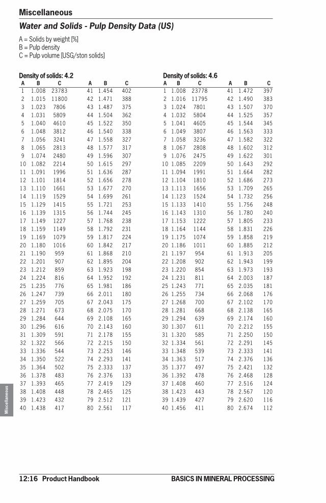
12:16 Product Handbook
MiscellaneousM
isce
llane
ous
BASICS IN MINERAL PROCESSING
Water and Solids - Pulp Density Data (US)A = Solids by weight [%]B = Pulp densityC = Pulp volume [USG/ston solids]
Density of solids: 4.2 Density of solids: 4.6A B C A B C A B C A B C1 1.008 23783 41 1.454 402 1 1.008 23778 41 1.472 3972 1.015 11800 42 1.471 388 2 1.016 11795 42 1.490 3833 1.023 7806 43 1.487 375 3 1.024 7801 43 1.507 3704 1.031 5809 44 1.504 362 4 1.032 5804 44 1.525 3575 1.040 4610 45 1.522 350 5 1.041 4605 45 1.544 3456 1.048 3812 46 1.540 338 6 1.049 3807 46 1.563 3337 1.056 3241 47 1.558 327 7 1.058 3236 47 1.582 3228 1.065 2813 48 1.577 317 8 1.067 2808 48 1.602 3129 1.074 2480 49 1.596 307 9 1.076 2475 49 1.622 301
10 1.082 2214 50 1.615 297 10 1.085 2209 50 1.643 29211 1.091 1996 51 1.636 287 11 1.094 1991 51 1.664 28212 1.101 1814 52 1.656 278 12 1.104 1810 52 1.686 27313 1.110 1661 53 1.677 270 13 1.113 1656 53 1.709 26514 1.119 1529 54 1.699 261 14 1.123 1524 54 1.732 25615 1.129 1415 55 1.721 253 15 1.133 1410 55 1.756 24816 1.139 1315 56 1.744 245 16 1.143 1310 56 1.780 24017 1.149 1227 57 1.768 238 17 1.153 1222 57 1.805 23318 1.159 1149 58 1.792 231 18 1.164 1144 58 1.831 22619 1.169 1079 59 1.817 224 19 1.175 1074 59 1.858 21920 1.180 1016 60 1.842 217 20 1.186 1011 60 1.885 21221 1.190 959 61 1.868 210 21 1.197 954 61 1.913 20522 1.201 907 62 1.895 204 22 1.208 902 62 1.943 19923 1.212 859 63 1.923 198 23 1.220 854 63 1.973 19324 1.224 816 64 1.952 192 24 1.231 811 64 2.003 18725 1.235 776 65 1.981 186 25 1.243 771 65 2.035 18126 1.247 739 66 2.011 180 26 1.255 734 66 2.068 17627 1.259 705 67 2.043 175 27 1.268 700 67 2.102 17028 1.271 673 68 2.075 170 28 1.281 668 68 2.138 16529 1.284 644 69 2.108 165 29 1.294 639 69 2.174 16030 1.296 616 70 2.143 160 30 1.307 611 70 2.212 15531 1.309 591 71 2.178 155 31 1.320 585 71 2.250 15032 1.322 566 72 2.215 150 32 1.334 561 72 2.291 14533 1.336 544 73 2.253 146 33 1.348 539 73 2.333 14134 1.350 522 74 2.293 141 34 1.363 517 74 2.376 13635 1.364 502 75 2.333 137 35 1.377 497 75 2.421 13236 1.378 483 76 2.376 133 36 1.392 478 76 2.468 12837 1.393 465 77 2.419 129 37 1.408 460 77 2.516 12438 1.408 448 78 2.465 125 38 1.423 443 78 2.567 12039 1.423 432 79 2.512 121 39 1.439 427 79 2.620 11640 1.438 417 80 2.561 117 40 1.456 411 80 2.674 112

Product Handbook 12:17
Miscellaneous
Mis
cella
neou
s
BASICS IN MINERAL PROCESSING
Water and Solids - Pulp Density Data (metric)A = Solids by weight [%]B = Pulp density [ton/m3]C = Pulp volume [m3/ton solids]
Density of solids: 5.0A B C A B C1 1.008 99.200 41 1.488 1.6392 1.016 49.200 42 1.506 1.5813 1.025 32.533 43 1.524 1.5264 1.033 24.200 44 1.543 1.4735 1.042 19.200 45 1.563 1.4226 1.050 15.867 46 1.582 1.3747 1.059 13.486 47 1.603 1.3288 1.068 11.700 48 1.623 1.2839 1.078 10.311 49 1.645 1.241
10 1.087 9.200 50 1.667 1.20011 1.096 8.291 51 1.689 1.16112 1.106 7.533 52 1.712 1.12313 1.116 6.892 53 1.736 1.08714 1.126 6.343 54 1.761 1.05215 1.136 5.867 55 1.786 1.01816 1.147 5.450 56 1.812 0.98617 1.157 5.082 57 1.838 0.95418 1.168 4.756 58 1.866 0.92419 1.179 4.463 59 1.894 0.89520 1.190 4.200 60 1.923 0.86721 1.202 3.962 61 1.953 0.83922 1.214 3.745 62 1.984 0.81323 1.225 3.548 63 2.016 0.78724 1.238 3.367 64 2.049 0.76325 1.250 3.200 65 2.083 0.73826 1.263 3.046 66 2.119 0.71527 1.276 2.904 67 2.155 0.69328 1.289 2.771 68 2.193 0.67129 1.302 2.648 69 2.232 0.64930 1.316 2.533 70 2.273 0.62931 1.330 2.426 71 2.315 0.60832 1.344 2.325 72 2.358 0.58933 1.359 2.230 73 2.404 0.57034 1.374 2.141 74 2.451 0.55135 1.389 2.057 75 2.500 0.53336 1.404 1.978 76 2.551 0.51637 1.420 1.903 77 2.604 0.49938 1.437 1.832 78 2.660 0.48239 1.453 1.764 79 2.717 0.46640 1.471 1.700 80 2.778 0.450
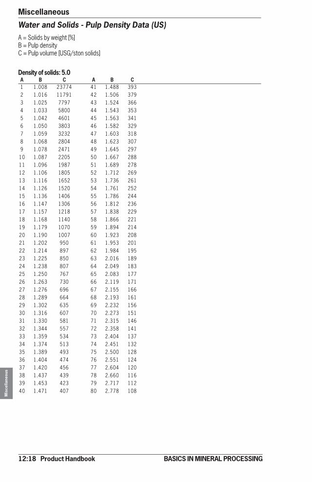
12:18 Product Handbook
MiscellaneousM
isce
llane
ous
BASICS IN MINERAL PROCESSING
Water and Solids - Pulp Density Data (US)A = Solids by weight [%]B = Pulp densityC = Pulp volume [USG/ston solids]
Density of solids: 5.0A B C A B C1 1.008 23774 41 1.488 3932 1.016 11791 42 1.506 3793 1.025 7797 43 1.524 3664 1.033 5800 44 1.543 3535 1.042 4601 45 1.563 3416 1.050 3803 46 1.582 3297 1.059 3232 47 1.603 3188 1.068 2804 48 1.623 3079 1.078 2471 49 1.645 297
10 1.087 2205 50 1.667 28811 1.096 1987 51 1.689 27812 1.106 1805 52 1.712 26913 1.116 1652 53 1.736 26114 1.126 1520 54 1.761 25215 1.136 1406 55 1.786 24416 1.147 1306 56 1.812 23617 1.157 1218 57 1.838 22918 1.168 1140 58 1.866 22119 1.179 1070 59 1.894 21420 1.190 1007 60 1.923 20821 1.202 950 61 1.953 20122 1.214 897 62 1.984 19523 1.225 850 63 2.016 18924 1.238 807 64 2.049 18325 1.250 767 65 2.083 17726 1.263 730 66 2.119 17127 1.276 696 67 2.155 16628 1.289 664 68 2.193 16129 1.302 635 69 2.232 15630 1.316 607 70 2.273 15131 1.330 581 71 2.315 14632 1.344 557 72 2.358 14133 1.359 534 73 2.404 13734 1.374 513 74 2.451 13235 1.389 493 75 2.500 12836 1.404 474 76 2.551 12437 1.420 456 77 2.604 12038 1.437 439 78 2.660 11639 1.453 423 79 2.717 11240 1.471 407 80 2.778 108