Embed Size (px)
Citation preview

SP52 S P H E R E S P E C T R O P H O T O M E T E R
Operator’s Manual


i
Dear X-Rite Customer:
Congratulations! We at X-Rite, Incorporated are proud to present you with a X-Rite SP52 Sphere Spectrophotometer. This instrument represents the very latest in microcontrollers, integrated circuits, optics, and display technology. As a result, your X-Rite instrument is a rugged and reliable instrument whose performance and design exhibit the qualities of a finely engineered instrument, which is not surpassed.
To fully appreciate and protect your investment, we suggest that you take the necessary time to read and fully understand this manual. As always, X-Rite stands behind your instrument with a one-year limited warranty, and a dedicated service organization. If the need arises, please don’t hesitate to call us. The X-Rite customer service telephone number is: 1-800-248-9748.
Thank you for your trust and confidence.
X-Rite, Incorporated

ii
Federal Communications Commission Notice This equipment has been tested and found to comply with the limits for a Class A digital device, pursuant to Part 15 of the FCC Rules. These limits are designed to provide reasonable protection against harmful interference when the equipment is operated in a commercial environment. This equipment generates, uses, and can radiate radio frequency energy and, if not installed and used in accordance with the instruction manual, may cause harmful interference to radio communications. Operation of this equipment in a residential area is likely to cause harmful interference in which case the user will be required to correct the interference at his own expense.
NOTE: Shielded interface cables must be used in order to maintain compliance with the desired FCC and European emission requirements.
Industry Canada Compliance Statement This digital apparatus does not exceed the Class A limits for radio noise emissions from digital apparatus set out in the Radio Interference Regulations of the Canadian Department of Communications. Le present appareil numerique n'emet pas de bruits radioelectriques depassant les limites applicables aux appareils numeriques de la class A prescrites dans le Reglement sur le brouillage radioelectrique edicte par le ministere des Communications du Canada. AVERTISSEMENT : Des câbles d'interface blindés doivent être utilisés afin de se conformer aux règlements européens et FCC (USA)sur l'émission.
ACHTUNG: Um das Produkt innerhalb der FCC (Vereinigten Staaten) und den europäischen Emissions-Richtlinien zu halten, müssen geschirmte Schnittstellenkabel verwendet werden. AVISO: Para satisfacer las deseadas regulaciones de emisión para Europa y el FCC, se debe utilizar los cables de interfaz protegidos contra las interferencias electromagnéticas. AVERTISSEMENT: Des câbles d’interface blindés doivent être utilisés afin de se conformer aux règlements d’émission européens et de FCC (Etats-Unis). AVVISO: Per conformare con i desiderati regolamentazioni di emissione per Europa ed il FCC, utilizzare i cavi d'interfaccia protetti contro l'interferenze electtromagnetiche.
WARNING: This instrument is not for use in explosive environment. WARNUNG: Das Gerät darf in einer explosiven Umgebung NICHT verwendet werden. ADVERTENCIA - NO use este aparato en los ambientes explosivos. ATTENTION: Cet instrument NE DOIT PAS être utilisé dans un environnement explosif. AVVERTIMENTO - NON usare questo apparecchio in ambienti esplosivi.

iii
CAUTION: Operational hazard exists if battery chargers other than X-Rite SE30-81 (115V) or SE30-77 (100-240V) is used. Use only X-Rite battery pack SP62-79-23, other types may burst causing personal injury. VORSICHT: Betriebs- und Verletzungsgefahr besteht bei Gebrauch von anderen Adaptern als X-Rite SE30-81 (115 V) oder SE30-77 (100-240 V). Verwenden Sie nur den X-Rite Akkupack SP62-79-23. ADVERTENCIA: No use otro cargador de las pilas que no sea la pieza X-Rite SE30-81 (115V) o SE30-77 (100-240V), para evitar el riesgo de mal funcionamiento del equipo. Use solamente las pilas SP62-79-23 de X-Rite, es posible que los otros tipos puedan estallar y causar daños corporales. ATTENTION: Pour ne pas causer un mauvais fonctionnement de l'appareil, veillez à utiliser uniquement les chargeurs de batterie X-Rite SE30-81 (115 V) ou SE30-77 (100-240 V). Veillez aussi à utiliser uniquement la batterie X-Rite SP62-79-23, d'autres batteries pouvant exploser et causer des blessures. AVVERTENZA: Non usare un altro caricabatterie che non è del pezzo X-Rite SE30-81 (115V) o SE30-77 (100-240V), per evitare il rischio di malfunzionamento dell'apparecchio. Usare solamente gli accumulatori SP62-79-23 di X-Rite, è possibile che altri tipi possano scoppiare e causare danno personale.
The Manufacturer: X-Rite, Incorporated Der Hersteller: 4300 44th Street, S.E. El fabricante: Grand Rapids, Michigan 49512 Le fabricant: Il fabbricante: Declares that: Spectrophotometer gibt bekannt dass: SP52 advierte que: avertit que: avverte che: is not intended to be connected to a public telecommunications network. nicht an ein öffentliches Telekommunikations-Netzwerk angeschlossen werden soll. no debe ser conectado a redes de telecomunicaciones públicas. ne doit pas être relié à un réseau de télécommunications publique. non deve essere connettuto a reti di telecomunicazioni pubblici.

iv
CE DECLARATION Manufacturer's Name: X-Rite, Incorporated Manufacturer's Address: 4300 44th Street, S.E. Grand Rapids, Michigan 49512 U.S.A. Model Name: Spectrophotometer Model No.: SP52 Directive(s) Conformance: EMC 89/336/EEC LVD 73/23/EEC
WEEE As of August 13, 2005, X-Rite products meet the European Union – Waste Electrical and Electronic Equipment (WEEE) directive. Please refer to www.xrite.com for more information on X-Rite’s compliance with the WEEE directive.
Warning: This is a class A product. In a domestic environment this product may cause radio interference in which case the user may be required to take adequate measures.

v
Table of Contents Proprietary Notice
Warranty Information 1 Overview and Setup 1-1
1.1 Instrument Description .............................................................. 1-1 1.2 Unpack and Inspect.................................................................... 1-2 1.3 Install the Battery Pack.............................................................. 1-2 1.4 Apply Power .............................................................................. 1-3 1.5 Charging the Battery Pack ......................................................... 1-3 1.6 Unlatching the Instrument Shoe ................................................ 1-4 1.7 Instrument I/O Serial Interface .................................................. 1-5 1.8 Attaching the Wrist Strap .......................................................... 1-5
2 User Interface 2-1 2.1 What to Expect .......................................................................... 2-1 2.2 Navigation – Basic Operation.................................................... 2-1
2.2.1 Tab Down key.................................................................. 2-2 2.2.2 Tab Up key....................................................................... 2-2 2.2.3 Enter key .......................................................................... 2-2 2.2.4 Escape key........................................................................ 2-2 2.2.5 Main Menu key ................................................................ 2-2 2.2.6 Read key........................................................................... 2-2
2.3 Measure Mode Screen ............................................................... 2-2 2.3.1 Sample Information.......................................................... 2-3 2.3.2 Controls............................................................................ 2-3 2.3.3 User Dialog ...................................................................... 2-3 2.3.4 Measurement Information ................................................ 2-3
2.4 Using the Instrument Keys ........................................................ 2-3 2.4.1 Opening a Mode or Menu ................................................ 2-4 2.4.2 Opening a Pop-Up List Box ............................................. 2-4 2.4.3 Using the Alphanumeric Editor........................................ 2-4 2.4.4 Using the Location/Sample Editor ................................... 2-5
2.5 Instrument Indicator Light......................................................... 2-5 2.6 Important Measurement Techniques ......................................... 2-6
3 Instrument Calibration 3-1 3.1 General Information................................................................... 3-1 3.2 Positioning the Instrument on the Reference ............................. 3-2 3.3 Calibration Procedure ................................................................ 3-3
4 Instrument Operations 4-1

vi
4.1 General Information................................................................... 4-1 4.1.1 Sample Averaging............................................................ 4-1
4.2 Measure Mode ........................................................................... 4-1 5 Instrument Configuration 5-1
5.1 General Information................................................................... 5-1 5.2 Language ................................................................................... 5-1 5.3 Database Tools .......................................................................... 5-2
5.3.1 Add Location Name or Sample Name ............................. 5-3 5.3.2 Factory Presets ................................................................. 5-4 5.3.3 Clear all Databases........................................................... 5-4 5.3.4 Clear All Samples ............................................................ 5-4 5.3.5 Clear All Locations .......................................................... 5-5
5.4 Security...................................................................................... 5-5 6 Service and General Maintenance 6-1
6.1 Repair Information .................................................................... 6-1 6.2 Cleaning the Instrument............................................................. 6-1
6.2.1 General Cleaning.............................................................. 6-1 6.2.2 Cleaning the Optics .......................................................... 6-1 6.2.3 Cleaning the Calibration Reference ................................. 6-2
6.3 Replacing the Battery Pack........................................................ 6-3 7 Appendices 7-1
7.1 Instrument Specifications .......................................................... 7-1 7.2 Error Messages .......................................................................... 7-2

vii
Proprietary Notice The information contained in this manual is derived from patent and proprietary data of X-Rite, Incorporated. This manual has been prepared solely for the purpose of assisting in the use and general maintenance of this instrument. The contents of this manual are the property of X-Rite, Incorporated and are copyrighted. Any reproduction in whole or part is strictly prohibited. Publication of this information does not imply any rights to reproduce or use this manual for any purpose other than installing, operating, or maintaining this instrument. No part of this manual may be reproduced, transcribed, transmitted, stored in a retrieval system, or translated into any language or computer language, in any form or by any means, electronic, magnetic, mechanical, optical, manual, or otherwise, without the prior written permission of an officer of X-Rite, Incorporated. This instrument may be covered by one or more patents. Refer to the instrument for actual patent numbers.
Copyright © 2007 by X-Rite, Incorporated “ALL RIGHTS RESERVED”
X-Rite® is a registered trademark of X-Rite, Incorporated. All other logos, brand names, and product names mentioned are the properties of their respective holders.
Warranty Information X-Rite, Incorporated (“X-Rite”) warrants each instrument manufactured to be free of defects in material and workmanship (excluding battery pack) for a period of 12 months. This warranty shall be fulfilled by the repair or replacement, at the option of X-Rite, of any part or parts, free of charge including labor, F.O.B. its factory or authorized service center. This warranty shall be voided by any repair, alteration, or modification, by persons other than employees of X-Rite, or those expressly authorized by X-Rite to perform repairs, and by any abuse, misuse, or neglect of the product, or by use not in accordance with X-Rite’s published instructions. X-Rite reserves the right to make changes in design and /or improvements to its products without any obligation to include these changes in any products previously manufactured. Correction of defects by repair or replacement shall constitute fulfillment of all warranty obligations on the part of X-Rite. THIS WARRANTY IS EXPLICITLY IN LIEU OF ANY OTHER EXPRESSED OR IMPLIED WARRANTIES, INCLUDING ANY IMPLIED WARRANTY OF MERCHANTABILITY OR FITNESS FOR ANY PARTICULAR PURPOSE. THIS WARRANTY OBLIGATION IS LIMITED TO REPAIR OR REPLACEMENT OF THE UNIT RETURNED TO X-RITE OR AN AUTHORIZED SERVICE CENTER FOR THAT PURPOSE. This agreement shall be interpreted in accordance with the laws of the State of Michigan and jurisdiction and venue shall lie with the courts of Michigan as selected by X-Rite, Incorporated.

viii

S P 5 2
S P H E R E S P E C T R O P H O T O M E T E R
1-1
1 Overview and Setup Instrument Description 1-1 Features 1-2 Unpacking and Inspection 1-2 Installing the Battery Pack 1-2 Applying Power 1-3 Charging Battery Pack 1-3 Unlatching the Instrument Shoe 1-4 Instrument I/O Serial Interface 1-5 Attaching the Wrist Strap 1-5
1.1 Instrument Description The SP52 Sphere Spectrophotometer is used to measure and store sample color readings. When samples are stored, the instrument is used in conjunction with a ColorDesigner software package.
The spectrophotometer can measure color samples on a variety of materials, including, paper, textiles and various painted objects.
Target Window
Graphic Display
I/O Port
Power Input
Escape KeyTab Key
Tab Key Main Menu Key
Read Key
Battery Switch
Indicator Light
Instrument Shoe
Enter Key

C H A P T E R O N E
1-2
1.2 Unpack and Inspect After removing the instrument from the shipping carton, inspect it for damage. If any damage has occurred during shipping, immediately contact the transportation company. Do not proceed with installation until the carrier’s agent has inspected the damage.
Your instrument was packaged in a specially designed carton to assure against damage. If shipment is necessary, the instrument should be packaged in the original carton. If the original carton is not available, contact X-Rite to have a replacement carton shipped to you.
1.3 Install the Battery Pack The instrument is shipped from the factory with the battery pack removed. The battery pack is located in a carrying case compartment and must be installed before the instrument is used. 1. Hold the shoe next to the instrument housing and lift
upward on the spring-loaded latch (refer to Unlatching the Instrument Shoe). Open the shoe perpendicular to the instrument housing.
2. Carefully rotate the instrument over and rest it on its top. 3. Slide the battery pack into the compartment with the battery
connector facing down and to the back of the instrument. 4. Press down on the pack until the connector is properly
seated and the tabs click into position.
Battery Connector
Battery Pack

O V E R V I E W A N D S E T U P
1-3
1.4 Apply Power The Battery switch—located on the back of the instrument—turns the instrument off and on during battery operation. When the AC adapter is attached, the instrument remains on and the battery switch has no effect.
Taking a measurement or pressing a key turns the instrument back on during a power-down. However, if the instrument is turned off with the battery switch you must turn it back on with the battery switch.
1.5 Charging the Battery Pack NOTE: The battery pack must be installed before plugging in the AC Adapter.
Only use the AC Adapter supplied or the optional battery charger (P/N SPCHG) to charge the battery pack. The battery pack must remain in the instrument at all times to operate. Before initial “remote” use of the instrument, charge the battery pack for approximately four hours. However, if immediate use is required, the instrument can be operated “tethered” to the AC adapter during battery charging.
To attach the AC adapter: 1. Verify that the voltage indicated on the adapter complies
with the AC line voltage in your area. If not, contact X-Rite or an authorized representative.
2. Insert the small plug from the adapter into the power-input connector on the instrument. (If you are using serial cable SE108-92, you may insert the small plug into the power connector at the end of the cable.)
Battery Switch
AC Adapter Input

C H A P T E R O N E
1-4
3. Plug the adapter into an AC wall receptacle.
1.6 Unlatching the Instrument Shoe The shoe can be pivoted open 180° from its closed position.
To Unlatch the Instrument Shoe: 1. Hold the shoe next to the instrument housing and lift
upward on the spring-loaded latch. 2. Slowly allow the shoe to pivot toward the back of the
instrument and release the latch.
To latch the Instrument Shoe: 1. Simply close the shoe to the instrument. The latch is
spring-loaded and automatically latches to the shoe catch.
Shoe Latch Lift Upwards
Small Plug
Adapter
Power Input
O V E R V I E W A N D S E T U P
1-5
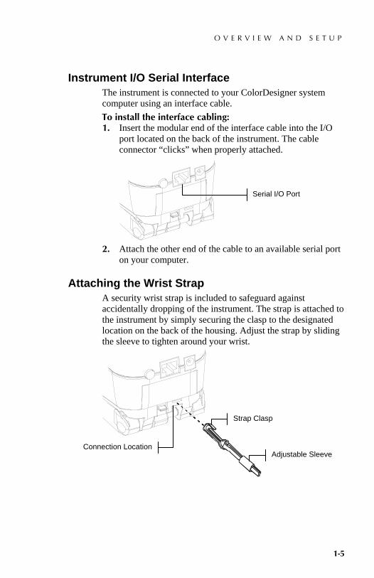
1.7 Instrument I/O Serial Interface The instrument is connected to your ColorDesigner system computer using an interface cable. To install the interface cabling: 1. Insert the modular end of the interface cable into the I/O
port located on the back of the instrument. The cable connector “clicks” when properly attached.
2. Attach the other end of the cable to an available serial port
on your computer.
1.8 Attaching the Wrist Strap A security wrist strap is included to safeguard against accidentally dropping of the instrument. The strap is attached to the instrument by simply securing the clasp to the designated location on the back of the housing. Adjust the strap by sliding the sleeve to tighten around your wrist.
Connection Location
Strap Clasp
Adjustable Sleeve
Serial I/O Port

C H A P T E R O N E
1-6

S P 5 2
S P H E R E S P E C T R O P H O T O M E T E R
2-1
2 User Interface What to Expect 2-1 Navigation – Basic Key Operation 2-1 Measurement Mode 2-2 Using the Instrument Keys 2-3 Instrument Indicator Light 2-3 Important Measurement Techniques 2-4
2.1 What to Expect When the instrument is powered-up, the Measure Mode screen appears. Measure Mode operation is covered in Section Four. The screen shown below is the main (top level) screen. The left side of the main menu screen lists all available modes. The right side of the screen lists instrument model and firmware version information.
–MAIN MENU– Measure Calibrate Configuration
SP52 —————— XXXX
* * * * * *
2.2 Navigation – Basic Operation Perform reading and mode/option navigation with the six keys arranged around the display screen. Each key has a unique symbol for performing a specific operation.
–MAIN MENU–
Measure Calibrate Configuration
SP52 —————— XXXX
* * * * * *
!$ @ #
%
Main Menu Key
Instrument Read Key
Tab Up Key Tab Down Key
Escape Key Enter Key
Serial Number
Firmware Version
Instrument Model

C H A P T E R T W O
2-2
2.2.1 Tab Down key Advances the highlighted bar (reverse image) to the next available “tab stop.” A “tab stop” indicates an item that can be acted on further, such as a menu item. Tab stops generally follow a left-to-right or top-to-bottom sequence.
2.2.2 Tab Up key Performs the same function as the Tab Down key except in reverse order. Tab stops follow a right-to-left or bottom-to-top sequence.
2.2.3 Enter key Activates the highlighted item. When entering an active mode from the main menu, the active mode is displayed with the highlight on the first required operation in the mode.
2.2.4 Escape key Backs up the instrument screen one menu level.
2.2.5 Main Menu key Returns the instrument screen to the main menu. This is a quick exit out of any mode. If any option is being modified at the time the key is pressed, the edits are aborted and the previous setting reinstated.
2.2.6 Read key Initiates a reading when pressed. Note, this function is only activated through an RCI command. Not all applications utilize this functionality.
2.3 Measure Mode Screen The Measure Mode screen consists of four main areas: Sample information, Controls, User dialog, and Measurement information.
Location A: Bedroom Sample 1: Door Trim
SAVE RESET
Averages:1
<Select a location>
@
$
#
!
%
Controls
Sample and/or Fan Deck Information
MeasurementInformation
User Dialog

U S E R I N T E R F A C E
2-3
2.3.1 Sample Information This area displays the location name, sample name and samples stored in the selected location. Pressing the Enter # key when Location is highlighted provides access to the selection editor. Pressing the Enter # key when Bedroom (user defined location name) or Door Trim (user defined sample name) is highlighted provides access to the location names or sample names stored in the instrument.
2.3.2 Controls This portion of the screen is used to save or reset the current sample measurement. Pressing the Enter # key when SAVE is highlighted stores the current measurement in the instrument. Pressing the Enter # key when RESET is highlighted reset the average counter to zero for the current sample.
2.3.3 User Dialog This portion of the screen indicates the current mode or condition of the instrument. For example, if the highlighted tab stop focus is on Location A, the user dialog would display <Select a location>. Measurement conditions are also displayed in this location.
2.3.4 Measurement Information This portion of the screen displays how many measurements have been completed on the current sample..
2.4 Using the Instrument Keys There are several techniques used to navigate through the instrument screens, select functions and settings, and define names.

C H A P T E R T W O
2-4
2.4.1 Opening a Mode or Menu Opening a mode or menu gives you access to additional items related to the menu or specific information for a mode.
–MAIN MENU– Measure Calibrate Configuration
SP52 —————— XXXX
* * * * * *
To open a mode or menu: 1. Use the Tab Up key $ or Tab Down key @ to highlight the
desired mode or menu item. 2. Press the Enter # key.
2.4.2 Opening a Pop-Up List Box Opening a pop-up list box allows you to select items and/or change settings for a selection or function. Below is an example of a list box.
Configuration Language : English Database Tools... Security is Off
To open an pop-up list box: 1. Use the Tab keys $@ to highlight the desired selection or
function. 2. Press the Enter # key to access the pop-up list box.
2.4.3 Using the Alphanumeric Editor Location and sample names can be edited using the alphanumeric editor if you do not have an optional barcode reader. Selecting Clear in the editor provides a quick method of removing all characters in the string. Pressing the Tab keys $@ simultaneously clears the selected character. Below is an example of the editor.
New Location Name Clear ↓ ooooooooo0000000000 ↑
Save & Exit
Configuration Language : English Database Tools... Security is Off
Set Language English Deutsch Français ↓
Pop-Up List Box
A -H ↑ B C D ↓
Editor

U S E R I N T E R F A C E
2-5
To open the editor: 1. Use the Tab $@ keys to choose the desired digit or number
location (arrows above and below designate selection). 2. Press the Enter # key to access the editor.
NOTE: You can press the Enter # key again to quickly page through groups of letters, symbols, and numbers. Use the Escape ! key to move from a character back to the group selection.
3. Use the Tab $@ keys to highlight the desired character. 4. Press the Enter # key to select the highlighted character
and exit the editor.
2.4.4 Using the Location/Sample Editor The measure mode has a special control that is used to select storage locations, location names, and sample names. The list can be paged through either forward or backward to reduce time.
Location A:Bedroom Sample 1: Door Trim
SAVE RESET
Averages:1
<Select a location>
To open the editor: 1. Use the Tab $@ keys to highlight the location, location
name, or sample name. 2. Press the Enter # key to activate the editor. 3. Press the Down Tab @ key to page forward through the list,
or press the Up Tab $ key to page backward through the list. 4. After the desired item is displayed, you can press the Enter
# key to select the item, or press the Escape ! key to go back to the original setting.
2.5 Instrument Indicator Light The LED located next to the screen illuminates various color conditions during instrument measurements. • Flashing Amber – instrument calibration is required or
measurement aborted. • Solid Amber – measurement is taking place.
Indicates the editor control is activated

C H A P T E R T W O
2-6
2.6 Important Measurement Techniques The variety of items that the instrument can measure is almost endless. However, to obtain accurate and repeatable measurements, the bottom of the shoe must be on the surface to be measured. The reason for this is that any movement during a reading can cause the data to vary. To obtain the most accurate and repeatable measurements, there are a few guidelines you must follow: • The sample to read must be larger than the target window
opening. • If the sample to be read is smaller than the shoe, you may
want to make a platform—the same height of the sample—for the instrument to sit on.
• The sample color should be uniform and consistent across the measurement area, with no fading or blemishes.
• The sample should be solid—not clear or translucent.

S P 5 2
S P H E R E S P E C T R O P H O T O M E T E R
3-1
3 Instrument Calibration General Information 3-1 Positioning the Instrument on the Reference 3-2 Calibration Procedure 3-3
3.1 General Information Under normal circumstances, the instrument should be calibrated at least once a day.
At the Main Menu, use the Tab Up $ or Tab Down @ key to highlight Calibrate. Press the Enter # key to access the Calibration Menu.
–MAIN MENU– Measure Calibrate Configuration
SP52 —————— XXXX
* * * * * *
The bottom portion of the calibration screen displays information regarding the calibration status, cal reference serial number, and instrument aperture size. The status line displays as either Cal OK or Cal time up. Cal time up indicates that calibration is required. Cal Ok indicates that no calibration is required at this time. The serial number displayed on the second line should match the serial number listed on your calibration reference. The aperture size line displays the current size.

C H A P T E R T H R E E
3-2
3.2 Positioning the Instrument on the Reference The calibration reference consists of a ceramic disk for white calibration measurements and a trap opening for black calibration measurements. The instrument shoe fits snuggly in both positions. Refer below for proper positioning.
NOTE: Make sure the calibration reference is clean before use. Refer to the calibration cleaning procedure in Section Six.
White Reading Position
Black Reading Position
White Ceramic Disk
Port Opening

I N S T R U M E N T C A L I B R A T I O N
3-3
3.3 Calibration Procedure A calibration procedure consists of a white measurement followed by a black measurement. The instrument notifies you when a calibration is required.
NOTE: The instrument must be calibrated with the target window removed when using the instrument with the shoe extended (unlatched).
To perform a calibration: 1. At the Calibration menu screen, position the target window
over the white ceramic disk as previously explained. CALIBRATION
<Measure White Ref> Status: Cal time up S/N: ****** Ap Size: 8.0mm
2. Press the instrument firmly to the shoe. Hold steady until the screen indicates the white calibration is completed. Release instrument when <Success!> is displayed.
3. Position the target window over the black port opening as previously explained.
4. Press the instrument firmly to the shoe. Hold steady until the screen indicates the black calibration is completed.
5. Store the calibration reference in a dry, dust free area, away from direct exposure to light.

C H A P T E R T H R E E
3-4
S P 5 2
S P H E R E S P E C T R O P H O T O M E T E R
4-1
4 Instrument Operations General Information 4-1 Measure Mode 4-1
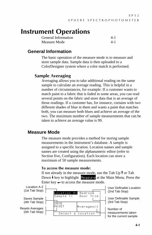
4.1 General Information The basic operation of the measure mode is to measure and store sample data. Sample data is then uploaded to a ColorDesigner system where a color match is performed.
4.1.1 Sample Averaging Averaging allows you to take additional reading on the same sample to calculate an average reading. This is helpful in a number of circumstances, for example: If a customer wants to match paint to a fabric that is faded in some areas, you can read several points on the fabric and store data that is an average of those readings. If a customer has, for instance, curtains with two different shades of blue in them and wants a paint that matches both, you can measure both blues and achieve an average of the two. The maximum number of sample measurements that can be taken to achieve an average value is 99.
4.2 Measure Mode The measure mode provides a method for storing sample measurements in the instrument’s database. A sample is assigned to a specific location. Location names and sample names are created using the alphanumeric editor (refer to Section five, Configuration). Each location can store a maximum of 50 sample measurements.
To access the measure mode: If not already in the measure mode, use the Tab Up $ or Tab Down @ key to highlight Measure at the Main Menu. Press the Enter key # to access the measure mode.
Location A: Bedroom Sample 1: Door Trim
SAVE RESET
Averages:1
Select a location
Location A-Z (1st Tab Stop)
User Definable Location (2nd Tab Stop)
Saves Sample (4th Tab Stop)
User Definable Sample (3rd Tab Stop)
Resets Averages (5th Tab Stop)
Number of measurements taken for the current sample

C H A P T E R F O U R
4-2
To measure and store a sample: 1. At the measure menu screen, make sure Location is
highlighted and select the desired location (refer to Section Two for procedure). Locations are labeled A – Z (excluding I and O).
2. After the location is selected, press the Tab Down @ key to move the highlight to the 2nd tab stop, location name. Select the desired location name (refer to Section Two). If no location names exist, <blank> is display. Location names are created by using the Add Location Name option (refer to Section 5, Configuration, Database Tools).
3. After the location name is selected, press the Tab Down @ key to move the highlight to the 3rd tab stop, sample name. Select the desired sample name (refer to Section Two). If no sample names exist, <blank> is display. Sample names are also created using the Add Sample Name option (refer to Section Five, Database Tools).
4. After all selections are made, position the instrument’s target window on the sample and take a measurement by lowering the instrument to the shoe and holding. Release the instrument when Measurement Complete is displayed. NOTE: Your measurement procedure may also require you to press the Read key when the instrument is lowered.
5. Continue with additional measurements if sample averaging is used.
NOTE: Highlighting RESET and pressing the Enter # key will set the Averages number to zero. This allows you to collect new measurement data on the current sample.
6. After measuring, press the Tab Down @ key to move the highlight to the 4th tab stop, SAVE. Press the Enter # key to store the sample in the database.

S P 5 2
S P H E R E S P E C T R O P H O T O M E T E R
5-1
5 Instrument Configuration General Information 5-1 Language 5-1 Database Tools 5-2 Security 5-5
5.1 General Information The configuration menu contains several menu items that can be modified to meet your individual requirements.
To access the Configuration menu: 1. At the Main Menu, use the Tab Up $ or Tab Down @ key to
highlight Configuration. Press the Enter # key to access the configuration menu.
–MAIN MENU– Measure Calibrate Configuration
SP52 —————— XXXX
* * * * * *
5.2 Language The Language configuration allows you to select the language you want to display on your instrument. The instrument resets whenever the language is changed.
To select a language: 1. Use the Tab $@ keys to highlight Language. 2. Press the Enter # key to access the Language editor.
Configuration
Language :English Database Tools... Security is Off...
3. Use the Tab $@ keys to highlight the desired language. 4. Press the Enter # key to save the selected language. The
instrument restarts with the selected language active.
English, Deutsch, Español, Francais, Italiano, Português

C H A P T E R F I V E
5-2
5.3 Database Tools The Database Tools allow you to configure the following settings: • Add Location Name – Used to manually enter location
names using the editor. • Add Sample Name – Used to manually enter sample
names using the editor. • Factory Presets – Allows you to reload the factory
default settings whenever required. Databases are not affected.
• Clear all Databases – Allows you to clear all stored samples from all locations. Configuration settings are not affected.
• Clear all Samples – Allows you to clear all stored samples (sample names are NOT deleted from the list).
• Clear all Locations – Allows you to clear all stored samples from all locations (location names are NOT deleted from the list).

I N S T R U M E N T O P E R A T I O N S
5-3
To open the Database Tools menu: 1. Use the Tab $@ keys to highlight Database Tools.
Configuration
Language :English Database Tools... Security is Off
2. Press the Enter # key to access the Database Tools menu.
5.3.1 Add Location Name or Sample Name To add a location name or sample name: 1. Use the Tab $@ keys to highlight Add Location Name or
Add Sample Name. Database Tools
Add Location Name... Add Sample Name... Factory Preset... Clear all Databases Clear all Samples Clear all Locations
2. Press the Enter # key to open the New Location Name or New Sample Name menu.
New Location Name Clear ↓ o ↑ Save & Exit
NOTE: To quickly remove a name, highlight Clear and press the Enter # key.
3. Use the Tab $@ keys to highlight the name entry field.
NOTE: If you are using the optional bar code reader, you may scan the name in at this point.
4. Use the Tab $@ keys to choose the desired character location (arrows above and below designate the selection). Press the Enter # key to access the alphanumeric editor.
5. Press the Enter # key again to quickly page through groups of letters, symbols, and numbers.
6. Use the Tab $@ keys to highlight the desired character and press the Enter # key to exit editor.
7. Continue with additional character edits.
Name entry field

C H A P T E R F I V E
5-4
8. When editing is completed, use the Tab $@ keys to highlight Save & Exit and press the Enter # key.
5.3.2 Factory Presets NOTE: All configuration options and stored data will be lost when reloading the factory defaults.
To restore factory presets: 1. Use the Tab $@ keys to highlight Factory Presets.
Database Tools Add Location Name... Add Sample Name... Factory Preset... Clear all Databases Clear all Samples Clear all Locations
2. Press the Enter # key to open the Factory Defaults window.
3. Use the Tab $@ keys to highlight Yes and press the Enter # key. The factory defaults are now loaded in the instrument.
5.3.3 Clear all Databases To clear database: 1. Use the Tab $@ keys to highlight Clear all Databases.
Database Tools Add Location Name... Add Sample Name... Factory Preset... Clear all Databases Clear all Samples Clear all Locations
2. Press the Enter # key to open the Delete Databases window.
3. Use the Tab $@ keys to highlight Yes and press the Enter # key. The instrument’s databases are now deleted.
5.3.4 Clear All Samples To clear all samples: 1. Use the Tab $@ keys to highlight Clear all Samples.
Database Tools Add Location Name... Add Sample Name... Factory Preset... Clear all Databases Clear all Samples Clear all Locations

I N S T R U M E N T O P E R A T I O N S
5-5
2. Press the Enter # key to open the Delete Samples window.
3. Use the Tab $@ keys to highlight Yes and press the Enter # key. The instrument’s samples are now deleted.
5.3.5 Clear All Locations To clear all locations: 1. Use the Tab $@ keys to highlight Clear all
Locations. Database Tools
Add Location Name... Add Sample Name... Factory Preset... Clear all Databases Clear all Samples Clear all Locations
2. Press the Enter # key to open the Delete Locations window.
3. Use the Tab $@ keys to highlight Yes and press the Enter # key. The instrument’s samples are now deleted.
5.4 Security When security is activated (on) the Configuration options menu will not appear on the instrument screen. See following steps to access the Configuration menu when Security is activated (on). To set the security option: 1. Use the Tab $@ keys to highlight Security is.
Configuration
Language :English Database Tools... Security is Off
2. Press the Enter # key to toggle between Off and On. 3. Press the Escape ! key to save and exit the configuration
menu.
NOTE: You must turn the instrument off and then back on for the to activate the security option.
To gain access to the Configuration menu if Security is enabled: 1. Remove the AC adapter and turn off the instrument with
the battery switch.

C H A P T E R F I V E
5-6
2. Press and hold the Read key as you turn the instrument on with the battery switch.
3. When the main menu appears, release the Read key. The Configuration item appears in the main menu.
NOTE: You must set the Security to Off if you want the Configuration item to automatically appear the next time you turn the instrument on.

S P 5 2
S P H E R E S P E C T R O P H O T O M E T E R
6-1
6 Service and General Maintenance Repair Information 6-1 Cleaning the Instrument 6-1 Replacing the Battery Pack 6-3
6.1 Repair Information The X-Rite SP52 instrument is covered by a one-year limited warranty—excluding battery pack—and should be referred to factory or authorized service center for repairs within the warranty period. Attempts to make repairs within this time frame may void the warranty.
X-Rite provides a factory repair service to their customers. Because of the complexity of the circuitry, all repairs should be referred to the factory or an authorized service center (call: 1-800-248-9748).
X-Rite will repair any instrument past warranty. The customer shall pay shipping cost to the factory or authorized service center and repair cost. The instrument shall be submitted in the original carton, as a complete unaltered unit.
6.2 Cleaning the Instrument Your instrument requires very little maintenance to achieve years of reliable operation. However, to protect your investment and maintain reading accuracy, a few simple cleaning procedures should be performed from time to time.
6.2.1 General Cleaning The exterior of the instrument may be wiped clean with a cloth dampened in water or mild cleaner whenever required.
NOTE: DO NOT use any solvents to clean the instrument; this causes damage to the cover.
6.2.2 Cleaning the Optics The optics should be cleaned once a week in normal environments, and more often in dirty or dusty environments. Carefully lift the instrument and blow short bursts of clean, dry air into the measurement aperture. This should remove any accumulated dust in the optics area. WARNING: DO NOT invert cans that use Freon as a propellant; doing so could cause damage to the optics assembly.

C H A P T E R S I X
6-2
6.2.3 Cleaning the Calibration Reference The calibration reference consists of a ceramic disk for white calibration measurements and a trap opening for black calibration measurements. The white ceramic disk can be cleaned periodically using a mild soap and warm water solution, thoroughly rinsed with warm water and wiped dry with a lint-free cloth. Do not use solvents or cleaners of any kind. The black trap portion of the reference should be cleaned with clean, dry air from time to time to remove any dust or contamination. The reference can be taken apart for easy cleaning of the black trap by compressing the two locking tabs on both sides of the case with your fingers, and separating the two sections. NOTE: When reassembling the black trap, make sure the trap opening is positioned over the cone in the bottom portion of the trap. The tabs will not lock correctly if assembled in the opposite direction.
Make sure to store the calibration reference in a dry, dust free area, away from direct exposure to light.
Trap Cone
Locking Tab
White Disk
Locking Tab

S E R V I C E A N D G E N E R A L M A I N T E N A N C E
6-3
6.3 Replacing the Battery Pack 1. Unplug the AC adapter and click the battery switch to Off. 2. Hold the shoe next to the instrument housing and lift
upward on the spring-loaded latch. Open the shoe perpendicular to the instrument housing. Refer to Unlatching the Instrument Shoe in Section One.
3. Carefully rotate the instrument over and rest it on its top. 4. Using your fingers, compress the two tabs located on both
sides of the battery pack and remove battery pack. 5. Slide a fresh battery pack into the compartment with the
battery connector facing down and to the back of the instrument.
6. Press down on the pack until the connector is properly seated and the tabs click into position.
Battery Pack
Pack Tabs
Battery Connection

C H A P T E R S I X
6-4

S P 5 2
S P H E R E S P E C T R O P H O T O M E T E R
7-1
7 Appendices Instrument Specifications 7-1 Error Messages 7-2
7.1 Instrument Specifications Measurement Geometrics d/8°, DRS spectral engine, choice of optical aperture:
8mm viewing/12mm illumination Light Source Gas-filled tungsten lamp Illuminant Types A, C, D50, D55, D65, D75, F2, F7, F11, & F12 Standard Observers (set by RCI) 2° & 10° Receiver Blue-enhanced silicon photodiodes Spectral Range 400nm – 700nm Spectral Interval 10nm – measured, 10nm – output Measurement Range 0 to 200% reflectance Measuring Time Approx. 2 seconds Inter-Instrument Agreement 0.20 ΔE*ab, based on avg. of 12 BCRA series II tiles
0.40 ΔE*ab max. on any tile (specular component included).
Short-Term Repeatability .05 ΔE*ab max. on white ceramic, standard deviation (specular component included).
Lamp Life Approx. 500,000 measurements Power Supply Removable (Ni-metal hydride) battery pack;
7.2 VDC rated @ 1250 mAh. AC Adapter Requirements 90-130VAC, 50-60Hz, 15W max Charge Time Approx. 4 hours – 100% capacity Measurements Per Charge 1,000 measurements typical Data Interface Patented bi-directional RS-232, 300-57,600 baud Display 128 x 256 pixel graphical LCD Operating Temperature Range 50° to 104°F (10° to 40°C)
85% relative humidity maximum (non-condensing) Storage Temperature Range -4° to 122°F (-20° to 50°C) Dimensions 4.3”H (10.9cm) 3.3”W (8.4cm) 7.7”L (19.6cm) Weight 2.4 lbs. (1.1 kg) Accessories Provided Calibration Standard, Manual,
AC Adapter, Carrying Case Usage Indoor only Altitude 2000m Pollution Degree 2 Overvoltage Category II X-Rite standards are traceable to National Research Council Canada, Laboratory for Basic Standards. Specifications and design subject to change without notice.

C H A P T E R S E V E N
7-2
7.2 Error Messages Errors encountered during a measurement are displayed on the instrument screen. All errors are accompanied by a long beep and flashing yellow light. The error message is cleared from the instrument screen by pressing the Enter # key.
Displayed Errors: Reason
Measurement was aborted by user
Displays with an incomplete measurement or calibration. Instrument was released too soon.
Calibration has timed out
The calibration interval time set in the configuration has been reached. Calibration is now required.
Calibration required
Displays anytime the instrument requires a calibration.
Calibration has failed
Calibration failed. Make sure the instrument is properly positioned on the reference.
The battery is getting low
This warning appears when the battery falls below approximately 25% of full charge. Measurements are still possible, but the battery should be charged soon.
Batteries are dead
Displays when not enough battery power remains to take measurement. The current measurement is aborted.
Batteries are missing
The battery pack is not installed. Instrument will not allow any measurements.
Incorrect Charger Voltage
Wrong charger is connected or charger is bad.
The battery is over–charged
The battery pack is too hot. Remove the battery pack and let it cool.
Lamp is getting weak, replace soon
Reading lamp is at 50% strength or less from its original intensity. Measurements are still possible but the lamp should be replaced soon.


P/N SP52-500 Rev. D
Corporate Headquarters - USA 4300 44th Street SE Grand Rapids, Michigan 49512 Phone 1 800 248 9748 or 1 616 803 2100 Fax 1 800 292 4437 or 1 616 803 2705 Corporate Headquarters - Europe Althardstrasse 70 8105 Regensdorf Switzerland Phone (+41) 44 842 24 00 Fax (+41) 44 842 22 22 Corporate Headquarters - Asia Room 808-810 Kornhill Metro Tower, 1 Kornhill Road Quarry Bay, Hong Kong Phone (+852) 2 568 6283 Fax (+852) 2 885 8610 Please visit www.xrite.com for a local office near you.