Embed Size (px)
Citation preview

Spolar Gold Premier
Table of Contents
About Your New Gold Premier…………………………………………………………………2
Guarantee And Warranty………………………………………………………………………..2
Reloading Safety…………………………………………………………………………………3
Unpacking The Gold Premier…………………………………………………………………..4
Installation………………………………………………………………………………………...4
Assembly………………………………………………………………………………………….5
Preloading……………………………………………………………………………………...…6
Special Reloading Instructions…………………………………………………………..……10
Loading Components…………………………………………………………………………..11
Starting To Load………………………………………………………………………………..12
Reloading………………………………………………………………………………………..15
Changing Gauges……………………………………………………………………………...17
Maintenance…………………………………………………………………………………….18
Lubrication………………………………………………………………………………………19
Washer Seal Removal And Replacement………………………………………………...…21
Replacing The Primer Cup…………………………………………………………………….21
Trouble Shooting……………………………………………………………………………….22
Sploar Doc.indd 1 1/2/2007 2:37:46 PM
ABOUT YOUR NEW GOLD PREMIER
Thank you for choosing the Spolar Power Load Gold Premier. This reloader has been designed by long-time shooters and experienced reloaders with the goal of creating the ultimate shotshell reloading machine. Its many unique features are the results of listening to reloading shooters critique the reloading machines that were already available, improving on the good features and developing better systems and devices to replace the not so good.
The basis for the Gold Premier was a design patented by the late Frank Simpson, a long time reloader and trap shooter. Frank has been inducted into the Oregon State Trapshooting Hall of Fame. His many years of experience with shooting, shooters, reloading and reloading equipment are evident in the reloading mechanisms that he patented. Unable to mass produce his reloaders because of their costly design, he built them one at a time.
Spolar Power Load, starting where Simpson left off, spent four years showing the original reloader to reloading enthusiasts and experts throughout the United States, soliciting suggestions and input. We designed and redesigned the original machine, based on the input received and what we observed while using it. Not until we were absolutely positive that the Gold Premier incorporated every conceivable improvement and feature and that it was better than any other reloader available, did we decide to go ahead with its manufacture.
The availability of master machinists, made possible by the slow down of the aero space industry, and Computer Numerical Controlled Machines, have enabled us to bring you a machine of a caliber that would have been economically impossible to produce previously. The Spolar Power Load Gold Premier is an unrivaled shotshell reloading machine, designed for the most discriminating of reloading shooters.
The first thing that you notice about the Gold Premier is that no expense has been spared in its manufacture. It incorporates the highest quality materials and components, machined to exacting aircraft-quality tolerances and standards, from billet aluminum and steel. Its movement is enhanced by sealed ball bearings and oil impregnated bronze bushings. There are no castings, stampings, plastic bushings or plastic parts other than the Spring Fingers, starter crimp, shot and powder bottles, primer tray cover and some electrical components. We are confident that the Gold Premier is the best shot shell reloader on the market today and we are prepared to stand behind it.
GUARANTEE AND WARRANTY
Like all Spolar products, the Gold Premier is covered by our one hundred percent, (100%) satisfaction guarantee. Send it back undamaged, within ten (10) days of receiving it and we will refund your purchase price.
2
Sploar Doc.indd 2 1/2/2007 2:37:46 PM
The Gold Premier is guaranteed against defects in material and workmanship for the life of the reloader. There are some parts on the Gold Premier such as the charge bar cam roller, spring fingers, springs, detent pins, vibrator motor, lubrication swabs etc., which by their very nature and function will wear out and need replacement. These parts, and parts that have been altered, abused, neglected or damaged by misuse or accidents are excluded from the warranty.
Whenever you have a problem with your reloader, please call us so we can walk you through identifying and correcting the cause. It has been our experience that most of the problems are caused by contamination; spilled shot or powder or just being dirty and not properly lubricated. The worse possible thing you can do if your Gold Premier is not functioning correctly is to start changing adjustments; the Spolar Gold Premier very rarely if ever comes out of adjustment.
RELOADING SAFETY
DO NOT OPERATE THE RELOADER UNTIL YOU HAVE READ THIS ENTIRE MANUAL.
Obtain a copy of the Sporting Arms and Manufacturers Institute Pamphlet on the characteristics of smokeless powder and follow their safety recommendations for the storage and handling of powder.
Powder should be kept in its original container in a dry, cool area away from possible sparks, flames and primers. Never leave unused powder in the reloader.
Always keep primers in their original containers until you are ready to use them. Store primers in an area away from flame, heat and powder.
WEAR SAFETY GLASSES WHILE RELOADING.
Always follow exactly the component combinations recommended in the tables provided by the component manufacturers. Do not experiment with combination that are not recommended by the manufacturers.
Weigh your shot and powder charges frequently, especially after changing powder batches or bushings.
Load only shotshell cases that are in good condition and not excessively worn.
NEVER LOAD SHOT OVER POWDER WITHOUT USING THE CORRECT WAD BETWEEN THEM; DOING SO CREATES THE MOST DANGEROUS SITUATION OF ALL, MOLTEN LEAD IN THE BARREL OF YOUR GUN.
When you reload, concentrate on reloading and avoid all distractions.
3
Sploar Doc.indd 3 1/2/2007 2:37:56 PM
DO NOT SMOKE OR DRINK ALCOHOL WHILE RELOADING.
Spolar Power Load will be working to develop a steel shot loading system for this reloader in the future. Until it is available, DO NOT LOAD STEEL SHOT WITH THIS RELOADER.
UNPACKING THE GOLD PREMIER
The Gold Premier shipping container consists of an outer carton and an inner carton which is suspended by shock absorbing foam pads. The loader in the inner carton is bolted to a ½” thick plywood retaining board which is locked down by a cardboard sleeve. The accessory carton is wedged in the space in front of the reloader.
OPEN THE CARTON CAREFULLY, PLAN ON SAVING THE ENTIRE SHIPPING CONTAINER.
Make sure that the carton is right side up. Cut each of the taped seams on the top side of the outer carton. Remove the owner’s manual and video or DVD from the top of the inner box. It is a good idea to read the “Unpacking the Gold Premier” section of the manual and/or watch the first part of the Video Manual or DVD, before proceeding. Remove the foam pad and set aside. Open the inner carton and lift out the Gold Premier, with shipping board attached, by grasping the circular, black Top Plate. Be careful that you do not bend any of the tooling. BE CAREFUL IF YOU HAVE A BAD BACK OR OTHER PHYSICAL LIMITATIONS; THE GOLD PREMIER WEIGHS SIXTY POUNDS. Unbolt the reloader from the plywood.
Carefully open the taped portions of the accessory carton, and remove The Primer Tray Assembly with attached Vibrator Motor, the Shot and Powder Bottles with attached Bases, Hex Wrenches, Lube Swab, Oil, Keys, Sizing Dies, Power Load Hydraulic, Replacement Stub Handle (if you have a Power Load Hydraulic) and four (4) 5/16 Flat Head Screws for attaching the Gold Premier to your loading bench and an AC/DC 9 Volt Converter for the Primer, Shot and Powder Settling System.
Reinstall both the nylon protective washers and carriage bolts in the shipping board, reassemble the empty carton and store it in a safe, dry place for use if it should be necessary to ship the loader in the future.
We advise against shipping the Gold Premier in anything but our containers and replacing lost or tossed containers is very expensive.
INSTALLATION
The reloader must be fastened to a sturdy, solidly built reloading bench that has absolutely no flex. We do not recommend anything less that 1 inch thickness, especially if you will be using a hydraulic attachment on your reloader. If your bench is constructed
4
Sploar Doc.indd 4 1/2/2007 2:38:06 PM

with a top made of one by twos, or two by fours or similar individual boards, it is important that the top be “locked together” with plywood. Otherwise, the boards will flex, particularly with a hydraulic. Use the (4) 5/16 flat head machine screws that we shipped with your loader, to secure it to your bench. It is important that the reloader does not move on the bolts. Re check for tightness after loading 500 shells and periodically after that.
ASSEMBLY
First remove the protective wrapping from the head of the reloader being careful not to scratch the surfaces. Next remove the 4 tie straps that secured your reloader for shipping with a pair of wire cutters or strong scissors, again be careful not to scratch the surface.
The only assembly required is: the reinstallation of the Primer Tray to the Primer Tray Arm and the Primer Track; the reinstallation of the Shot and Powder Bottles; reinstalling the Dies; the installation of the Spent Primer Box and plugging in the AC/DC converter. All of the non-adjustable screws and bolts have been secured with Loctite, however we have had instances of them coming loose in transit. Visually examine your entire reloader for loose or missing parts, screws and bolts. Please note, the bolt on the index cam appears to be loose, but that is the correct setting Please call us immediately if any others have come loose and we will walk you through getting it all back into original condition. PLEASE DO NOT READJUST THE RELOADER. WE DID NOT SHIP IT UNTIL IT WAS ABSOLUTELY PERFECTLY ADJUSTED.
PRIMER TRAY AND PRIMER TRACK
Unwrap the Primer Tray. Remove the allen head bolt that is sticking out of the bottom of the Primer Tray. Place the Tray on the Primer Tray Arm. The Arm fits into the slot on the bottom of the Tray. Replace the bolt and tighten it securely to attach the Tray.
Attach to the Primer Track to the Tray by placing it between the Primer Track Clamp and the underside of the Tray. Remove the Pin in the top of the Tray and open the lid all of the way back. Open the clamp by loosening the 2 allen head bolts on the top of the tray. Insert the Primer Track Tab between the Tray and the open Clamp and align the Track Groove to the Tray. Looking from the top, the left side of the track should touch the tray and the right side should be about 1/8 of an inch away from the tray, it will be about a 25 degree angle. Once the correct Track position is achieved, tighten the allen bolts to close the Clamp. The Video/ DVD Manual shows the entire procedure. Refer to the Video/DVD if the primers do not fall smoothly from the Tray into the Track for adjustments.
Plug the wires from the Electrical Box onto the Vibrator Motor leads. The Black Wire attaches to the Black colored lead, the plain colored wire to the plain colored lead.
SHOT AND POWDER BOTTLES
The four-inch diameter Shot Bottle threads into the rear threaded Bottle Holder on top of the loader, the smaller Powder Bottle threads into the front Bottle Holder. When installing, turn the bottles by holding the metal bases. Do not twist the plastic bottles
5
Sploar Doc.indd 5 1/2/2007 2:38:16 PM
themselves. The bases should be very tight, or they will tend to work out. These bottles were previously installed and fitted at the factory; if you reinstall them correctly, the labels “SHOT” and “POWDER” will face the front of the reloader.
DIES
To install the Dies, turn the spring-loaded DIE HOLD DOWN PLATE until the scalloped indentations line up with the holes, drop the Dies, long side down, into the holes and release the Die Hold Down Plate. A second method is to bring the handle forward to about the eleven o’clock (viewed from the handle side) position. The scallops on the Die Hold Down Plate will line up with the Die Holes in the Turret.
PRIMER SETTLING SYSTEM
The AC/DC Converter plugs into the jack located directly below the ON/OFF switch on the right side of the Electrical Accessory Box. The switch on the left is the Momentary Switch; it activates the Primer, Shot and Powder Settling System when it contacts the Charge Bar Cam Roller. NOTE: Push the ON/OFF switch off anytime the handle is in the forward position for any length of time to shut the vibrator off. Do not run the motor when you are not actually reloading.
SPENT PRIMER BOX
Slide the Spent Primer Box onto the stainless steel bracket on the front of the reloader by hooking the lip of the box into the groove of the bracket.
PRELOADING
Please don’t sit down in front of the Gold Premier with the attitude that now that you have this state of the art reloader you are going to load 100 shells during the first 10 minutes. Take the time to become familiar with your new machine; it will be time well spent. We recommend that you get the feel of the Gold Premier by slowly cycling it 15 to 20 times a dry, before filling it with components.
When you start out, moving the handle slowly, the first part of the stroke will be effortless. About on quarter of the way down you will encounter “resistance” as the Index Cam starts to engage the Index Rollers. This “resistance” is something you won’t feel as you get used to the machine, and start pulling the handle faster. Watch how the reloader functions. Notice the indexing system on the back left of the machine and the location of the handle when the Die Turret starts to turn. IF YOU HAVE THE POWER LOAD HYDRAULIC, PLEASE DO NOT HOOK IT UP TO THE GOLD PREMIER JUST YET. Load several boxes of shells by hand, get the feel of this fine machine and learn just how it works.
Concentrate on pulling the handle all of the way forward and pushing it all of the way back with a steady, even motion. This is the type of motion necessary if your goal is to achieve the highest quality, most accurate reloads possible. If you see powder falling after the Powder Drop Tube is out of the shell, you are pushing the handle too fast between the 12 o’clock and 2 o’clock, full back, position. If your movements during reloading are quick and jerky, regardless of the quality of the reloader that you are using,
6
Sploar Doc.indd 6 1/2/2007 2:38:26 PM

the shells that you produce will not be consistent and neither will your shooting scores. Before operating the Gold Premier with the Power Load Hydraulic, we further recommend that you load at least 40 to 50 rounds by hand. A firm grasp of the operating basics of this fine piece of equipment will pay off, not only by eliminating the possibility of a frustrating reloading experience but with better ammunition and hopefully better shooting scores.
Find the “neutral” position by pulling the handle slightly forward, until the Die Turret clears the Shell Seating Post. Now, pull the Index Cam, located at the back left of the Die Turret, back away from the rollers and move the Die Turret counter clockwise to any position you chose. If you ever perform this function while reloading, make absolutely certain that the shells are returned to the proper alignment under the correct station so that the shells will not be receiving double charges of shot and powder when you begin reloading again. DOUBLE CHECK THE SHELLS UNDER THE POWDER AND SHOT DROP TUBES BY REMOVING THE DIES AND SHELLS AND LOOKING AT THE CONTENTS.
If you have previously loaded with Hornady or MEC reloaders, the counter clockwise rotation of the Gold Premier is just what you are used to. If you have been reloading with a Ponsness/Warren, it may take you a while to get used to the different direction.
Notice that as long as the Charge Bar Cam Roller has not entered the angle at the bottom of the Charge Bar Cam, (the slotted, triangular shaped plate at the rear of the reloader) the loader can be reversed. ONCE THE CHARGE BAR INDEX ROLLER HAS ENTERED THE ANGLED SECTION OF THE CAM DO NOT BACK THE RELOADED UP WITHOUT PULLING THE CHARGE BAR DETENT PIN. BACKING UP AT THIS POINT, WITHOUT PULLING THE PIN, WILL REFILL THE BUSHINGS AND COULD LEAD TO A DOUBLE CHARGE.
Because of the ball-bearing movement, the handle of the Gold Premier moves easier than that of any other reloader, this smooth and almost effortless action takes some getting used to. To demonstrate the consequence of moving the handle to too fast, put a primer in the Primer Cup and move the reloader handle backward as fast as you can. The Primer Shaft may bounce against the Reloader Base and ninety-nine times out of a hundred the primer will bounce sideways or upside down. Handle movement fast enough to flip the primer, also means that it is moving so fast, especially between the handles 12:00 o’clock and 2:00 o’clock positions, that the powder and shot do not have enough time to drop properly into the hulls and some powder may fall on the Die Turret or the Base Plate . A smooth consistent 3 or 3-1/2 second complete cycle is similar to the cycle of our hydraulic actuator and is equivalent to 1000 to 1200 rounds an hour. Attempt to achieve a similar or slower rate when loading by hand. Moving the handle faster is not consistent with good reloading.
CHARGE BAR CAM PIN AND ROLLER
The Gold Premier is shipped with the Charge Bar Cam Pin and Roller installed. Please note that the Charge Bar Cam Pin has been installed from the left side and the Pin ring is always on the left side. The Cam Roller is installed small end first, from the right side. It fits all of the way over the Pin and through the Charge Bar Cam, and attaches the Charge Bar Cam Linkage to the Cam. It is essential that the Pin and Roller be properly
7
Page 5 Continued
6. Lamp Fuse .................................................................................................. V26367. Fuse Holder Cap ........................................................................................ V26378. A/C Adapter Plug ....................................................................................... V26399. ON/OFF Momentary Switch Button (serial# 315-536 only) ..................... V2634
*SPECIFY GAUGE
Sploar Doc.indd 7 1/2/2007 2:38:26 PM

installed. A few symptoms of incorrect installation are: The Ring interferes with the Primer Track; the Roller pops off of the Pin, the large part of the Roller does not contact the Vibrator Switch. An improperly installed Pin will damage the Track and Charge Bar Cam. Take care that you do not switch the Charge Bar Cam Pin with either the Primer Cover Detent Pin, or the Hydraulic Handle Detent Pin. The Charge Bar Cam Pin is identified by a black ring.
Practice disarming the charging system, by pulling the Charge Bar Cam Detent Pin that attaches the Charge Bar Cam Roller to the Charge Bar Cam and Charge Bar Linkage. (After removal, leave the Pin and Roller attached to each other to prevent loss). This disarming feature is useful if you should have a loading malfunction and don’t want to risk recharging the bushings. It alleviates the possibility of dropping a double charge. When the Charge Bar Cam Detent Pin is pulled, you can manually activate the Charge Bar by pushing or pulling it back and forth in its housing. The Shot and Powder Bushings can be emptied in this manner too, but BE SURE TO HOLD AN EMPTY SHELL OR OTHER CONTAINER UNDER THE SHOT DROP AND/OR POWDER DROP TUBE TO CATCH THE CONTENTS OF THE BUSHINGS. The Charge Bar can be removed from the Charge Bar Housing for cleaning when necessary. Move the Shot Bottle and Powder Bottle to the detent position left of center.( Look at the top of the charge bar and make certain that the shot and powder Bushings are empty, it they are not, refer to the above paragraph to empty them). This is the Off position. Pull the Charge Bar Cam Roller Detent Pin and unscrew the Counter Trip Pin from the front left side of the Charge Bar. Be sure that the bushings are empty. Push or pull the Charge Bar out of the back of the Charge Bar Housing. Be careful, as the Bar clears the Housing, the bushings will drop out of the Charge Bar if you don’t hold them, When reinstalling the Charge Bar, always be absolutely certain that there are Bushings in the Charge Bar.
LOADING WITHOUT BUSHINGS WILL DANGEROUSLY OVER CHARGE YOUR SHELLS.
Use only Spolar/Hornady Bushings in the Spolar Reloader. Other Brands of Bushings may have the same outside diameter, but sometime due to the lack of quality control they are often either to short or to long. Either condition will adversely impact safe consistent reloading. In addition NEVER use steel bushing in your Spolar; they can damage the Washer Seals and the aluminum Charge Bar Housing.
CHANGING BUSHINGS
To change Bushings move the Shot and/or Powder Bottles to the left, OFF POSITION. Make sure that the bushing you are going to remove is empty, to remove it, the eraser end of a pencil or a brass barrel cleaning brush is perfect for this, then drop the new bushing into the charge bar. ONCE AGAIN, BE SURE THAT YOU REPLACE THE BUSHINGS. NEVER OPERATE THE LOADER WITHOUT BUSHINGS IN THE CHARGE BAR. THE RESULT WILL BE A MASSIVELY OVER CHARGED SHELL.
If you removed the Charge Bar Cam Detent Pin and Roller, replace them. Push the On/Off Switch on the Electrical Accessory Box to turn it on. Now move the Handle forward watching how the Primer, Shot and Powder Settling System activates when the
8
PAGE 5
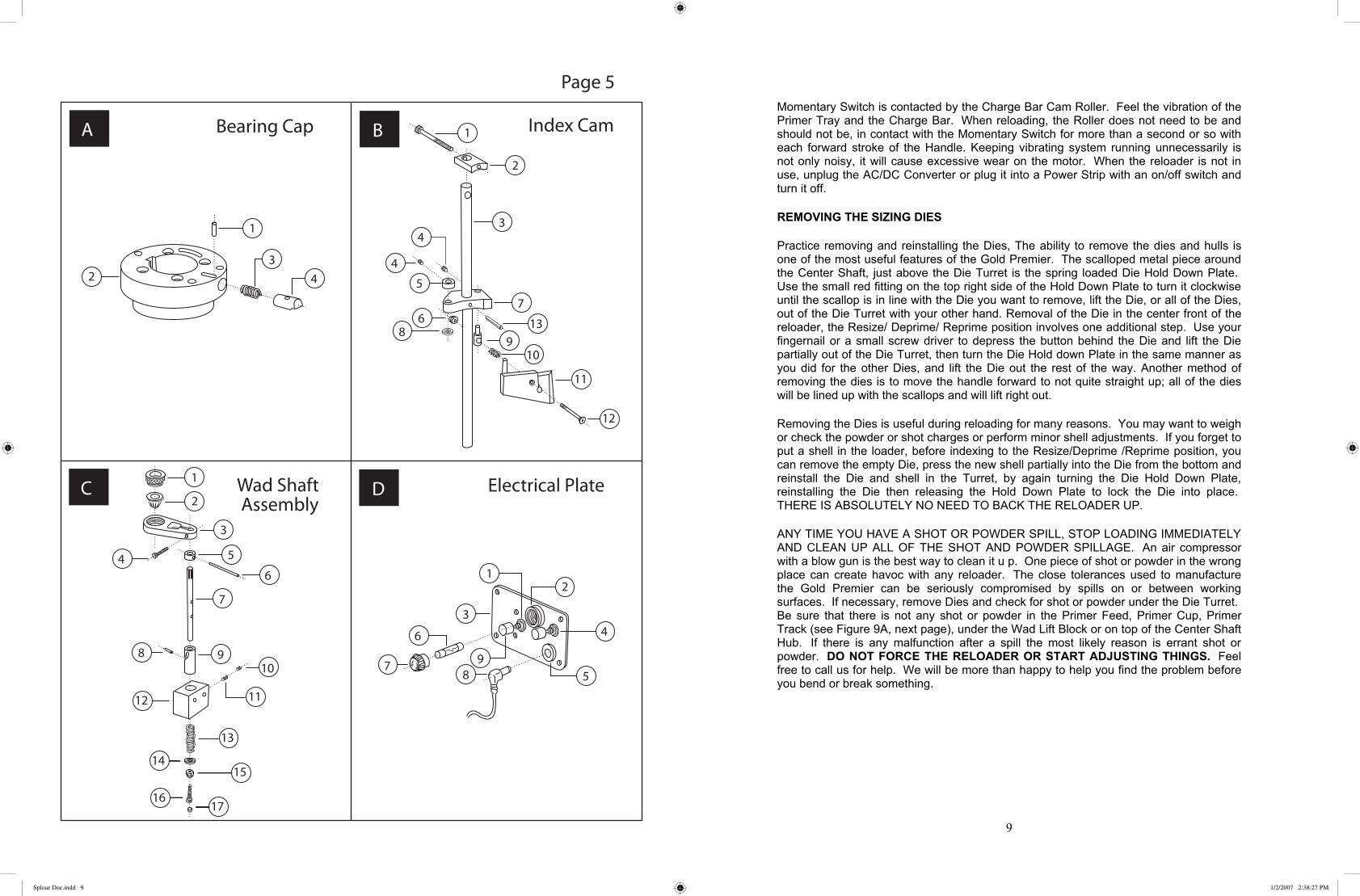
A. Bearing Cap1. 1/8 x 3/8 Roll Pin ....................................................................................... F1838RP-23052. Bearing Cap ............................................................................................... 23063. Die Retaining Plunger Spring .................................................................... S23054. Die Retaing Plunger ................................................................................... 2305
B. Index Cam1. 10/32 x 1-1/2 SHCS ................................................................................... F1032112SH-24012. Index Cam Support .................................................................................... 22043. Index Cam Shaft ........................................................................................ 22034. 10/32 x 3/16 Set Screw .............................................................................. F1032316SS-22095. Index Cam Keeper ..................................................................................... 22096. 6/32 Lock Nut ............................................................................................ F632LN-22117. Index Cam Block ....................................................................................... 22088. Index Cam Washer (on some models) ....................................................... 22109. Index Short Subshaft .................................................................................. 220710. Index Cam Spring ...................................................................................... S220611. Index Cam Assembly ................................................................................ 220612. Index Cam Bolt .......................................................................................... 221113. 1/8 x 7/8 Roll Pin....................................................................................... 0
C. Wad Shaft Assembly 1. Wad Cup ..................................................................................................... 27042. Spring Fingers ............................................................................................ V27043. Wad Arm .................................................................................................... 27034. 10/32 x 5/8 ................................................................................................. F103258SH-27035. Wad Shaft Keeper ..................................................................................... 27076. 1/8 x 1-1/4 Roll Pin .................................................................................... F18114RP-27077. Wad Shaft ................................................................................................... 27018. Wad Cam Dowell Pin ................................................................................. 27099. Wad Shaft Cam .......................................................................................... 270510. 10/24 x 3/16 Set Screw .............................................................................. F1024316SS-270611. 10/24 x 3/8 Half Dog Set Screw ................................................................ F102438HDSS-270612. Wad Shaft Block ........................................................................................ 270613. Wad Shaft Spring ....................................................................................... S270114. 1/4 Flat Washer .......................................................................................... F14FW-270115. 1/4 Lock Nut .............................................................................................. F14LN-270116. 10/32 x 3/4 SHCS ...................................................................................... F103234SH-270117. Wad Shaft Button ....................................................................................... 2702
D. Electrical Plate1. Momemtary Switch .................................................................................... V26382. Fuse Holder ................................................................................................ V26353. Electric Box Plate ...................................................................................... 26264. ON/OFF Switch ......................................................................................... V26335. Power Jack ................................................................................................. V2632
**
Sploar Doc.indd 8 1/2/2007 2:38:26 PM
Momentary Switch is contacted by the Charge Bar Cam Roller. Feel the vibration of the Primer Tray and the Charge Bar. When reloading, the Roller does not need to be and should not be, in contact with the Momentary Switch for more than a second or so with each forward stroke of the Handle. Keeping vibrating system running unnecessarily is not only noisy, it will cause excessive wear on the motor. When the reloader is not in use, unplug the AC/DC Converter or plug it into a Power Strip with an on/off switch and turn it off.
REMOVING THE SIZING DIES
Practice removing and reinstalling the Dies, The ability to remove the dies and hulls is one of the most useful features of the Gold Premier. The scalloped metal piece around the Center Shaft, just above the Die Turret is the spring loaded Die Hold Down Plate. Use the small red fitting on the top right side of the Hold Down Plate to turn it clockwise until the scallop is in line with the Die you want to remove, lift the Die, or all of the Dies, out of the Die Turret with your other hand. Removal of the Die in the center front of the reloader, the Resize/ Deprime/ Reprime position involves one additional step. Use your fingernail or a small screw driver to depress the button behind the Die and lift the Die partially out of the Die Turret, then turn the Die Hold down Plate in the same manner as you did for the other Dies, and lift the Die out the rest of the way. Another method of removing the dies is to move the handle forward to not quite straight up; all of the dies will be lined up with the scallops and will lift right out.
Removing the Dies is useful during reloading for many reasons. You may want to weigh or check the powder or shot charges or perform minor shell adjustments. If you forget to put a shell in the loader, before indexing to the Resize/Deprime /Reprime position, you can remove the empty Die, press the new shell partially into the Die from the bottom and reinstall the Die and shell in the Turret, by again turning the Die Hold Down Plate, reinstalling the Die then releasing the Hold Down Plate to lock the Die into place. THERE IS ABSOLUTELY NO NEED TO BACK THE RELOADER UP.
ANY TIME YOU HAVE A SHOT OR POWDER SPILL, STOP LOADING IMMEDIATELY AND CLEAN UP ALL OF THE SHOT AND POWDER SPILLAGE. An air compressor with a blow gun is the best way to clean it u p. One piece of shot or powder in the wrong place can create havoc with any reloader. The close tolerances used to manufacture the Gold Premier can be seriously compromised by spills on or between working surfaces. If necessary, remove Dies and check for shot or powder under the Die Turret. Be sure that there is not any shot or powder in the Primer Feed, Primer Cup, Primer Track (see Figure 9A, next page), under the Wad Lift Block or on top of the Center Shaft Hub. If there is any malfunction after a spill the most likely reason is errant shot or powder. DO NOT FORCE THE RELOADER OR START ADJUSTING THINGS. Feel free to call us for help. We will be more than happy to help you find the problem before you bend or break something.
9
Sploar Doc.indd 9 1/2/2007 2:38:27 PM

SPECIAL RELOADING INSTRUCTIONS
.410 RELOADING
The .410 shell is the most difficult to reload. Follow these recommendations to achieve the best results.
It is very important to keep the .410 hulls sorted by brand, type and the number of times the hulls have been shot because all of these factors affect the capacity and length of this tiny hull. For instance, The AA HS hulls load completely different than the Old AA hulls. The old AA cases that are stamped “MAX” are approximately .80 (eighty thousandths) longer than early AA cases without the stamp. To complicate the picture a little further there are two types of “MAX” cases. The AA hulls with “MAX” stamped in silver ink, and has a larger capacity than the earlier one, which is stamped in black. The different types of AA hulls should be sorted and loaded in separate batches. The Remington STS .410 case has a huge capacity and needs to be loaded differently again! The crimp depth needs to be set according to each batch type.
While loading the .410, because of its minuscule size, crimp adjustments are critical. A once fired case holds fewer components than one that has been fired two or three times because the inside of the case burns out rapidly with each firing, increasing the capacity. You will notice that as the capacity increases, the .410 crimp will dish slightly more with each reloading. We recommend that those who load the .410 sort their shells by the number of times that they have been fired and load these batches separately, adjusting the crimp depth differently for each batch, Adjusting the Crimp Die up or down should be all that is necessary to create an acceptable looking crimp. It should not be necessary to adjust the Radius or Starter Crimp. If you have difficulty with the .410, please call us. We will be happy too walk you through any problems.
.410 3 INCH RELOADING
In order to reload the 3 inch .410 cases you must have the gauge change kit that has been specifically made to load these hulls. The kit consist of not only the different tool head, with a special crimp die for the 3 inch hull, but a special wad finger spacer.
28 GAUGE RELOADING
The 28 gauge is the second most difficult case to reload. The same problems that occur in the .410 may be encountered in the 28, but they will not be as severe. To correct these problems, follow the same procedures recommended for the smaller bore.
Your machine was set up to reload the hull that you specified,. In our opinion the AA 28 HS hull, is the best at this time. In mid 2006 Winchester changed the 28 gauge HS hull and made it .040 longer and they are not marked any differently than the original HS. Watch for these hulls and keep them sorted separately because they will crimp differently. If you load the smooth Remington cases you can use the same components. The only change necessary is to turn the Crimp Die up about two turns, the Starter Crimp up about two turns both from the top of the top plate and adjust the radius crimp up on the nut above the cup, about two turns to get an acceptable crimp. Don’t forget to turn it back down turn when you go back to AA H S cases.
10
45. 6/32 x 3/4 SHCS ........................................................................................ F63234SH-261846. Swivel Spacer ............................................................................................. 264347. Primer Can Bracket Spacers ...................................................................... 262848. Swivel Arm ................................................................................................ V262049. Swivel Arm Stud ........................................................................................ 262350. Primer Return Spring ................................................................................. S262351. Male Primer Shaft ...................................................................................... 261752. PrimerDeflector ......................................................................................... V264153. Primer Slide Roller Bolt ............................................................................. 262954. Primer Return Spring Lock Nut 5/16 x 1/4 ................................................ F51614LN-261755. 6/32 x 1/4 BHCS ........................................................................................ F63214BH-261856. 10/32 x 1/4 BHCS ...................................................................................... F103214BH-262457. Primer Slide Roller .................................................................................... 2303-261358. Primer Block Sleeve .................................................................................. 261959. Primer Can Bracket .................................................................................... V264360. Swivel Block .............................................................................................. 262461. 1/4 x 3/8 SB ............................................................................................... F1438SB-230162. Female Primer Slide Stop Screw ............................................................... 262863. Female Primer Slide ................................................................................... 261364. Forward Spacer Spring .............................................................................. S262465. Primer Can ................................................................................................. V264266. Primer Can Pad .......................................................................................... 2642
Page 4 Continued
Sploar Doc.indd 10 1/2/2007 2:38:27 PM

If you have trouble with shot bridging, try adding a little graphite to your shot.
16 GAUGE RELOADING
The 16 gauge is difficult to reload, not be cause of the size of the hull, but because it is difficult to find good quality components, especially wads that correctly fit the hulls available in this gauge and which load correctly, sometimes you even have to use spacer wads to correct the fit. Most of our Spolar owners who shoot the 16 gauge have varied brands of empty hulls with both 8 point and 6 point crimps. When we ship a 16 gauge, Gauge Change, we have set it up, as close to perfect we possibly can, you will have to zero the 16 in yourself. After you receive it and are in the process of doing this with your components, please call us about any particular problems you are encountering and we will be happy to work together with you to get it perfect
20 AND 12 GAUGE RELOADING
As long as you are using the right wad, it is not necessary to adjust the crimp differently for different brands of shells in these gauges. The only crimp adjustments needed are those of personal preference. Indications of the wrong wad (wad column height) are shot being higher or lower than where the shell is going to fold, as it leaves the shot drop station.
LOADING COMPONENTS
Your shells cannot be any better than the sum total of your components. It is our recommendation that you use top quality shot, primers, powder and wads and shot shells that are in good condition. It is foolhardy to attempt to get “every last load” out of a shot shell. Not only is the chance of a reloading accident greatly enhanced by using tired cases, the chance of a shooting accident becomes much more likely. A blown off case or base wad lodged in the barrel has blown up more than one fine gun. In addition, the ballistics for cases that have been loaded too many times are very inferior to those achieved with shells that have not been loaded more than five times.
PRIMERS
Open the Primer Tray Cover by pulling the front detent pin out of the aluminum Primer Tray and swinging the Primer Tray Cover back. Try to leave the pin itself in the plastic cover so the pin and its spacer do not get lost or confused with the Charge Bar Cam Pin which is a different length. To fill the tray with primers turn the closed box of primers upside down on the Primer Tray surface, and then slide the paper cover off the inner primer package, while pressing the inner package down firmly. With the new style Primer Tray Cover Hinge and Detent Hinge Pin, if space behind the reloader does not permit the Primer Tray Cover to swing back fully, pull the Detent Hinge Pin to completely remove the cover. If you have the original fixed type Primer Tray Cover Hinge, split the paper primer tray sleeve along the back or where it is perforated and pull it from under the inner package while holding the inner package down tight on the tray. Carefully lift the inner package off the primers. Close the cover and activate the Momentary Switch on the Electrical Accessory Box until the primers move all the way down into the Primer
11
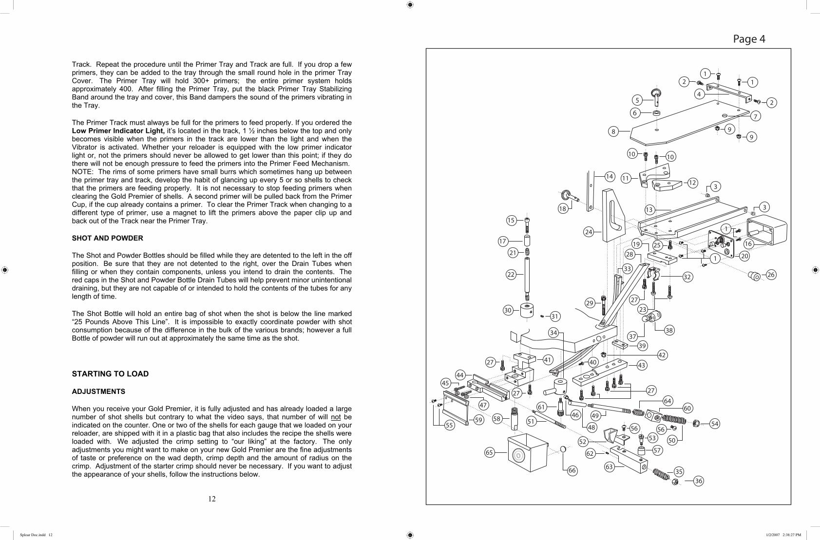
1. 6/32 x 3/8 BHCS ........................................................................................ F63212BH-26052. 6/32 x 3/8 BHCS ........................................................................................ F63238BH-26053. Primer Tray Hinge Spacer .......................................................................... 26064. Primer Tray Hinge...................................................................................... 26055. Primer Tray Lid Detent Pin 1/4 x x3/4....................................................... F1434DP-26046. Primer Tray Pin Spacer .............................................................................. 26077. Single Primer Drop Hole8. Primer Tray Cover...................................................................................... 26049. 6/32 Locknut .............................................................................................. F632LN-260510. 10/32 x 1/2 SHCS ...................................................................................... F103212SH-261011. Left Primer Tray Segment .......................................................................... 260212. Right Primer Tray Segment ....................................................................... 260313. Primer Tray ................................................................................................ 260114. Charge Bar Linkage - Long ....................................................................... 251815. Primer Cup Bolt ......................................................................................... 260016. Electrical Box ............................................................................................. 262517. Primer Cup ................................................................................................. 261518. Charge Bar Cam Roller Detent Pin 1/4 x 1 (Black Ring) .......................... F141DP-251019. Primer Tray Support ................................................................................... 261120. Electrical Switch Plate Assembly ............................................................. See Page 5 section D21. Primer Seating Spring ................................................................................ S261522. Primer Shaft ............................................................................................... 261423. 10/32 x 7/8 SHCS (2 Qty) .......................................................................... F103278SH-260124. Charge Bar Cam ......................................................................................... 251525. 10/32 x 1/2 SHCS ...................................................................................... F103212SH-260126. Charge Bar Cam Roller .............................................................................. 251027. 10/32 x 5/8 SHCS ...................................................................................... F103212SH-260928. Primer Tray Arm ........................................................................................ 260929. 10/32 x 1-1/4 SHCS ................................................................................... F1032114SH-260930. Primer Shaft Weight ................................................................................... 261631. Primer Shaft Weight Set Screw 10/32 x 3/16 ............................................ F103216SS-261632. Motor Bracket ............................................................................................ V263133. Primer Track............................................................................................... V264034. Swing Arm Hub ......................................................................................... 262035. Primer Ram Spring .................................................................................... S261736. Primer Ram Spring Locknut 5/16x24 ........................................................ F51624LN-261737. Motor Eccentric ......................................................................................... 262738. Vibrator Motor ........................................................................................... V263039. Primer Track Clamp ................................................................................... 261040. 6/32 x 1/4 BHCS ........................................................................................ F63214BH-261241. Primer Block .............................................................................................. 261842. 10/32 Locknut ............................................................................................ F632LN-260943. Charge Bar Cam Support ........................................................................... 251644. Male Primer Feed ....................................................................................... 2612
PRIMER TRAY FEEDING SYSTEMPAGE 4
Sploar Doc.indd 11 1/2/2007 2:38:27 PM
Track. Repeat the procedure until the Primer Tray and Track are full. If you drop a few primers, they can be added to the tray through the small round hole in the primer Tray Cover. The Primer Tray will hold 300+ primers; the entire primer system holds approximately 400. After filling the Primer Tray, put the black Primer Tray Stabilizing Band around the tray and cover, this Band dampers the sound of the primers vibrating in the Tray.
The Primer Track must always be full for the primers to feed properly. If you ordered the Low Primer Indicator Light, it’s located in the track, 1 ½ inches below the top and only becomes visible when the primers in the track are lower than the light and when the Vibrator is activated. Whether your reloader is equipped with the low primer indicator light or, not the primers should never be allowed to get lower than this point; if they do there will not be enough pressure to feed the primers into the Primer Feed Mechanism. NOTE: The rims of some primers have small burrs which sometimes hang up between the primer tray and track, develop the habit of glancing up every 5 or so shells to check that the primers are feeding properly. It is not necessary to stop feeding primers when clearing the Gold Premier of shells. A second primer will be pulled back from the Primer Cup, if the cup already contains a primer. To clear the Primer Track when changing to a different type of primer, use a magnet to lift the primers above the paper clip up and back out of the Track near the Primer Tray.
SHOT AND POWDER
The Shot and Powder Bottles should be filled while they are detented to the left in the off position. Be sure that they are not detented to the right, over the Drain Tubes when filling or when they contain components, unless you intend to drain the contents. The red caps in the Shot and Powder Bottle Drain Tubes will help prevent minor unintentional draining, but they are not capable of or intended to hold the contents of the tubes for any length of time.
The Shot Bottle will hold an entire bag of shot when the shot is below the line marked “25 Pounds Above This Line”. It is impossible to exactly coordinate powder with shot consumption because of the difference in the bulk of the various brands; however a full Bottle of powder will run out at approximately the same time as the shot.
STARTING TO LOAD
ADJUSTMENTS
When you receive your Gold Premier, it is fully adjusted and has already loaded a large number of shot shells but contrary to what the video says, that number of will not be indicated on the counter. One or two of the shells for each gauge that we loaded on your reloader, are shipped with it in a plastic bag that also includes the recipe the shells were loaded with. We adjusted the crimp setting to “our liking” at the factory. The only adjustments you might want to make on your new Gold Premier are the fine adjustments of taste or preference on the wad depth, crimp depth and the amount of radius on the crimp. Adjustment of the starter crimp should never be necessary. If you want to adjust the appearance of your shells, follow the instructions below.
12
Sploar Doc.indd 12 1/2/2007 2:38:27 PM

If you need to adjust wad or crimp depth, we recommend when performing any of these adjustments you load just one shell into the reloader. Work it through the reloader turning the powder on and then immediately off, so you just charge the bushing once, and drop powder into just the single shell. It is to your advantage to put just one shell in the loader and run it through the cycle to adjust wad depth, crimp depth and radius crimp so you don’t produce a lot of unsatisfactory shells.
Pulling the Index Cam back off the Rollers prevents the Turret from indexing and will keep the shell in the same position for making crimp adjustments. BE SURE THAT THE SHOT AND POWDER ARE TURNED OFF WHEN ADJUSTING THE CRIMPS. Raiseand lower the Turret while making slight adjustments until the shell has the appearance you want at the wad seating and crimp stations.
POWDER IS CHARGED WHEN HANDLE IS MOVED FORWARD. POWDER ISDROPPED WHEN THE HANDLE IS MOVED BACK.
TURN THE POWDER OFF WHEN THE HANDLE IS BACK TO KEEP FROMRECHARGING THE POWDER BUSHING. THE SHOT BUSHING IS CHARGED WHEN THE HANDLE IS MOVED BACK.
SHOT IS DROPPED WHEN THE HANDLE IS MOVED FORWARD.
TURN THE SHOT OFF WHEN THE HANDLE IS FORWARD, TO AVOIDRECHARGING THE BUSHING.
WAD DEPTH ADJUSTMENT
Loosen the Jam Nut at the top of the Wad Seating/Shot Drop Tube with your right hand while holding the Tube in your left hand. This nut is independent of the Shot Drop Tube. Turn the Tube counter clockwise to raise it if the wad is too deep or the opposite way to lower it if you want it deeper. WHILE THE HANDLE IS STILL IN THE BACK POSITION, TURN THE SHOT ON. INSERT A WAD INTO THE WAD CARRIER AND BRING THE HANDLE FORWARD. WHILE THE HANDLE IS STILL FORWARD, TURN THE SHOT OFF. Push the handle back. If the shot is above the fold line, take the shell and Die out of the Turret and dump the shot back into the Shot Bottle. Reinsert the shell and Die back into the Turret, loosen the Jam Nut and turn the Wad Seating/Shot Drop Tube down (clockwise) a little bit, tighten Jam Nut. Turn the shot on and reach behind the left side of the Turret and pull the Index Cam back so the machine will not index. Pull the Handle forward. Another charge of shot will be dropped. With the Handle still forward TURN THE SHOT OFF. Push the Handle back and examine the wad depth, if it still is not deep enough empty the shot out of the shell and repeat the process.
DO NOT GET THE WAD SEATING/SHOT DROP TUBE TOO LOW OR IT WILL HIT AND DAMAGE THE WAD CARRIER.
Keep the same shell in the reloader and do all of your preference adjustments on the same shell. When you are satisfied with the shot level, tighten the lock nut and index shell into the pre-crimp position.
13
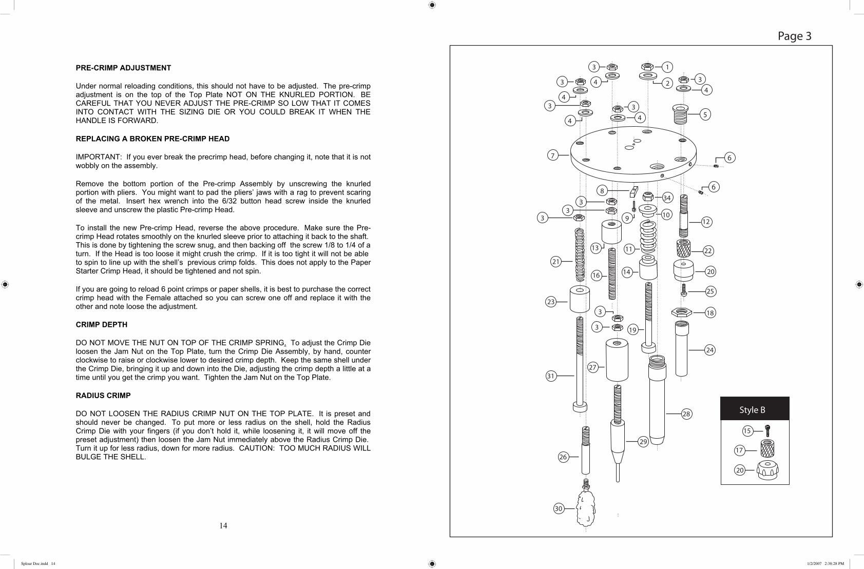
TOP PLATE ASSEMBLYPAGE 3
1. 3/8 x 24 Jam Nut (.410=5/16 x 24) ............................................................ F3824J(F51624JN)2. 3/8 Flat Washer (.410=5/16 Flat Washer) .................................................. F38FW(F516FW)3. 5/16 x 24 Jam Nut ...................................................................................... F51624JN4. 5/16 Flat Washer ........................................................................................ F516FW5. Shot Adapter ............................................................................................... 24416. 10/32 x 3/16 Set Screw .............................................................................. F1032316SS-24017. Top Plate .................................................................................................... 24018. Upper Key .................................................................................................. 24029. 6/32 x 5/8 SHCS ........................................................................................ F63212SH-240110. Spring Seat ................................................................................................. 246311. Crimp Ram Spring ..................................................................................... S246112. Starter Crimp-Male .................................................................................... 245113. Radius Crimp Cup...................................................................................... 247314. Crimp Cup .................................................................................................. 246215. Starter Crimp Head Bolt 12/20ga ............................................................. 245716. Radius Crimp Shaft .................................................................................... 247117. Starter Crimp-Female 12/20ga .................................................................. 245318. Shot Drop Tube Jam Nut............................................................................ 244319. Crimp Ram ................................................................................................. 246120. Starter Crimp Head .................................................................................... 245421. Knockout Spring ........................................................................................ S248122. Starter Crimp-Female 28/.410 .................................................................. 245323. Knockout Cup ............................................................................................ 248324. Shot Drop Tube .......................................................................................... 244225. Starter Crimp Head Bolt 12/20/28 ( after #475) ........................................ 2455 .410................................................................... 245626. Lube Shaft .................................................................................................. 241127. Deprime Cup .............................................................................................. 242228. Powder Drop Tube ..................................................................................... 243129. Deprime Shaft ............................................................................................ 242130. Lube Swab ................................................................................................. V241131. Knockout Shaft Assembly .......................................................................... 24812482
*
**
**
**
***
*
*
*SPECIFY GAUGE
Sploar Doc.indd 13 1/2/2007 2:38:28 PM
PRE-CRIMP ADJUSTMENT
Under normal reloading conditions, this should not have to be adjusted. The pre-crimp adjustment is on the top of the Top Plate NOT ON THE KNURLED PORTION. BE CAREFUL THAT YOU NEVER ADJUST THE PRE-CRIMP SO LOW THAT IT COMES INTO CONTACT WITH THE SIZING DIE OR YOU COULD BREAK IT WHEN THE HANDLE IS FORWARD.
REPLACING A BROKEN PRE-CRIMP HEAD
IMPORTANT: If you ever break the precrimp head, before changing it, note that it is not wobbly on the assembly.
Remove the bottom portion of the Pre-crimp Assembly by unscrewing the knurled portion with pliers. You might want to pad the pliers’ jaws with a rag to prevent scaring of the metal. Insert hex wrench into the 6/32 button head screw inside the knurled sleeve and unscrew the plastic Pre-crimp Head.
To install the new Pre-crimp Head, reverse the above procedure. Make sure the Pre-crimp Head rotates smoothly on the knurled sleeve prior to attaching it back to the shaft. This is done by tightening the screw snug, and then backing off the screw 1/8 to 1/4 of a turn. If the Head is too loose it might crush the crimp. If it is too tight it will not be able to spin to line up with the shell’s previous crimp folds. This does not apply to the Paper Starter Crimp Head, it should be tightened and not spin.
If you are going to reload 6 point crimps or paper shells, it is best to purchase the correct crimp head with the Female attached so you can screw one off and replace it with the other and note loose the adjustment.
CRIMP DEPTH
DO NOT MOVE THE NUT ON TOP OF THE CRIMP SPRING. To adjust the Crimp Die loosen the Jam Nut on the Top Plate, turn the Crimp Die Assembly, by hand, counter clockwise to raise or clockwise lower to desired crimp depth. Keep the same shell under the Crimp Die, bringing it up and down into the Die, adjusting the crimp depth a little at a time until you get the crimp you want. Tighten the Jam Nut on the Top Plate.
RADIUS CRIMP
DO NOT LOOSEN THE RADIUS CRIMP NUT ON THE TOP PLATE. It is preset and should never be changed. To put more or less radius on the shell, hold the Radius Crimp Die with your fingers (if you don’t hold it, while loosening it, it will move off the preset adjustment) then loosen the Jam Nut immediately above the Radius Crimp Die. Turn it up for less radius, down for more radius. CAUTION: TOO MUCH RADIUS WILL BULGE THE SHELL.
14
Sploar Doc.indd 14 1/2/2007 2:38:28 PM

LUBE SWAB
The Lube Swab, screws into the Top Plate directly over the Shell Seating Post, and automatically keeps the Dies lubricated. A little lubrication not only makes it easier to resize the shells, it keeps the Dies clean and rust free. The honey like consistency of Spolar Die Lube assures a clinging, wiping action. After reloading every 500 or so shells apply 5 or 6 drops of the Spolar Die Lube to your fingers, then to the bottom portion of the Lube Swab. The amount applied should be just enough to leave the Dies a little slick. Under no circumstances should so much be applied that the Dies are oily.
RELOADING
STEP ONE
With the Handle all the way forward, place shell on the Shell Seating Post.
STEP TWO
Smoothly push the Handle all of the way back bringing the Press Plate, Die Turret and Resizing Dies completely down over the shell, seating the shell in the Resizing Die.
STEP THREE
Smoothly pull the Handle forward. The first shell will index to the right into the Depriming/Resizing/Repriming Position. The old primer will drop into the Spent Primer Box. Place a second shell on the shell seating post.
STEP FOUR
Push the Handle back with smooth even motion, bringing the Die Assembly down over the second shell. The first shell will pick up a primer from the Primer Seating Cup and the second shell will be seated in the Resizing Die.
STEP FIVE
Move the Powder Bottle to the center directly over the Charge Bar. Pull the Handle forward, dropping a powder charge into the first shell and depriming the second shell.
STEP SIX
Place a third shell on the Shell Seating Post, push the Handle smoothly all of the way back again putting a shell into a Resizing Die.
STEP SEVEN
Put a wad in the Wad Cup. NOTE: you may have developed the habit of tapping the wad into the Wad Cup of other reloaders. DO NOT TAP THE WAD DOWN INTO THE
15
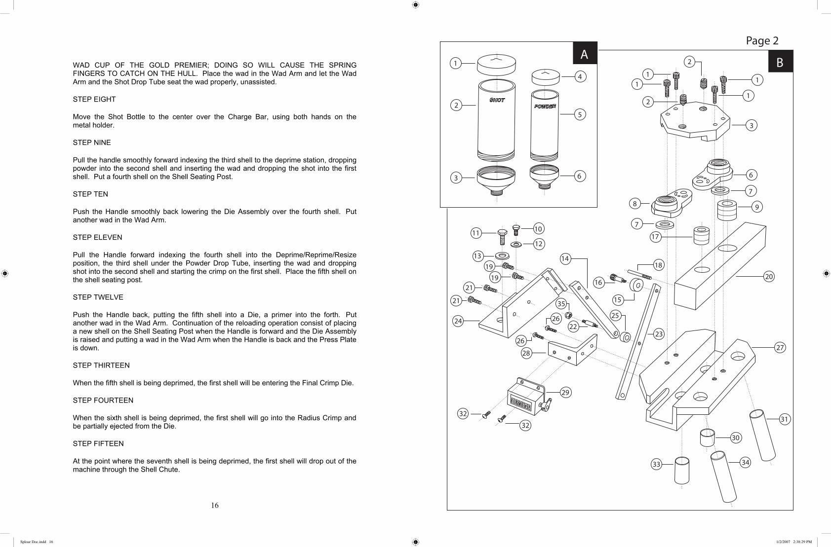
SECTION B1. 10/32 x 1 SHCS (4 Qty) ............................................................................. F10321SH-25012. 3/8 x 16 21lb Detent Ball Plunger .............................................................. F381621LBBP-25013. Charge Bar Cap .......................................................................................... 25036. Shot Bottle Holder ..................................................................................... 25067. Washer Seal ................................................................................................ V2505-068. Powder Bottle Holder ................................................................................ 25059. Shot Bushing .............................................................................................. See bushing chart10. 5/16 x 24 HHCS ......................................................................................... F51624HH11. 3/8-16 x 1 HHCS ....................................................................................... F3816HH12. 5/16 Flat Washer ........................................................................................ F516FW13. 3/8 Flat Washer .......................................................................................... F38FW14. Charge Bar Linkage-Short ......................................................................... 251915. Charge Bar Roller ...................................................................................... 250916. Charge Bar Roller Shoulder Bolt ............................................................... 264917. Powder Bushing ......................................................................................... See bushing chart18. Counter Pin ................................................................................................ 242419. 10/32 x 3/8 SHCS ...................................................................................... F103238SH-251920. Charge Bar ................................................................................................. 250221. 10/32 x 1/2 SHCS ...................................................................................... F103212SH-250122. Charge Bar Linkage Stud ........................................................................... 252523. Charge Bar Linkage-Long ......................................................................... 251824. Charge Bar Holder Bracket ........................................................................ 251725. Charge Bar Linkage Spacer ....................................................................... 251426. 6/32 x 3/8 BHCS ........................................................................................ F63237BH-250127. Charge Bar Holder ..................................................................................... 250128. Counter Bracket ......................................................................................... 252129. Counter ....................................................................................................... V252130. Shot Transfer Tube ..................................................................................... 251131. Shot Drain Tube ......................................................................................... 251332. 6/32 x 1/4 BHCS ........................................................................................ F63214BH-252133. Powder Transfer Tube ................................................................................ 251234. Powder Drain Tube .................................................................................... 251335. 1/4 x 28 Locknut ........................................................................................ F1428LN
CHARGE BAR HOLDER ASSEMBLYPAGE 2
SECTION A1. Shot Bottle Cap .......................................................................................... V25232. Shot Bottle ................................................................................................. 25233. Shot Bottle Adapter .................................................................................... 25084. Powder Bottle Cap ..................................................................................... V25225. Powder Bottle ............................................................................................. 25226. Powder Bottle Adapter ............................................................................... 2507
Sploar Doc.indd 15 1/2/2007 2:38:29 PM
WAD CUP OF THE GOLD PREMIER; DOING SO WILL CAUSE THE SPRING FINGERS TO CATCH ON THE HULL. Place the wad in the Wad Arm and let the Wad Arm and the Shot Drop Tube seat the wad properly, unassisted.
STEP EIGHT
Move the Shot Bottle to the center over the Charge Bar, using both hands on the metal holder.
STEP NINE
Pull the handle smoothly forward indexing the third shell to the deprime station, dropping powder into the second shell and inserting the wad and dropping the shot into the first shell. Put a fourth shell on the Shell Seating Post.
STEP TEN
Push the Handle smoothly back lowering the Die Assembly over the fourth shell. Put another wad in the Wad Arm.
STEP ELEVEN
Pull the Handle forward indexing the fourth shell into the Deprime/Reprime/Resize position, the third shell under the Powder Drop Tube, inserting the wad and dropping shot into the second shell and starting the crimp on the first shell. Place the fifth shell on the shell seating post.
STEP TWELVE
Push the Handle back, putting the fifth shell into a Die, a primer into the forth. Put another wad in the Wad Arm. Continuation of the reloading operation consist of placing a new shell on the Shell Seating Post when the Handle is forward and the Die Assembly is raised and putting a wad in the Wad Arm when the Handle is back and the Press Plate is down.
STEP THIRTEEN
When the fifth shell is being deprimed, the first shell will be entering the Final Crimp Die.
STEP FOURTEEN
When the sixth shell is being deprimed, the first shell will go into the Radius Crimp and be partially ejected from the Die.
STEP FIFTEEN
At the point where the seventh shell is being deprimed, the first shell will drop out of the machine through the Shell Chute.
16
Sploar Doc.indd 16 1/2/2007 2:38:29 PM

CLEARING THE SHELLS OUT OF THE LOADER
If you want to run all of the shells out to clear the reloader, work the last shell through to the Powder Drop Position. After that shell has received powder move the Handle back to lower the Die Turret. Move the Powder Bottle to the Off Position. Bring the Handle forward and bring the shell into the Shot Drop Position. After the shot has been dropped, while the Turret is still up and the Handle is forward, move the Shot Bottle to the Off position to the left. IF THE SHOT IS NOT TURNED OFF WHILE THE HANDLE IS FORWARD, THE SHOT BUSHING WILL BE RECHARGED WHEN THE HANDLE IS PUSHED BACK. If you make a mistake and recharge the Shot Bushing be sure to pull the Charge Bar Detent Pin to deactivate the Charging System. With the Pin pulled you can activate the Bar manually to empty the Bushing through the Shot Drop Tube, catching the charge in an empty shell or other container. Continue operating the Reloader until the last shell is finished. If you want to remove the primers from the Primer Track, use a magnet to lift the primers in the Track back toward the Primer Tray and out the top of the Track.
CHANGING GAUGES
Drain the Shot and Powder Bottles by detenting them one at a time to the
right over the Drain Tubes.
Remove the 10-32 Bolt that secures the Index Shaft to the back of the Top Plate.
Remove Detent Pin and Roller from the Charge Bar Cam.
Remove the Bolts from the top of the Top Plate and lift off the Charging System, remove the Shot Transfer Block
Lift off the Top Plate by placing your fingers under the Top Plate, close to the Center Shaft and lifting up.
Replace the Top Plate with the Top Plate of the correct gauge. Install the Shot Transfer Block on top of the Top Plate, over the Shot Transfer Tube, with the angle side sloping down to the right. Install the Charge Bar Housing making sure that the Shot Tube male end seats into the Shot Transfer Block female end, and the Powder Tube male end seats into the female Powder Tube on the Top Plate. Failure to do this properly will cause the Tubes to bend when you tighten the Top Bolts.
17
44. Pillow Block Sealed Bearing ..................................................................... V210545. Cross Shaft ................................................................................................. 210446. Pillow Block............................................................................................... 210547. Handle Bolt 5/16 x 24 x 1-1/4 SHCS......................................................... F51624114SH-210449. 1/4 x 28 x 3/4 SHCS .................................................................................. F142834SH-210950. Handle ........................................................................................................ 210651. Serial Number Plate52. Base Plate ................................................................................................... 210153. Primer Shaft Stop ....................................................................................... 210254. 1/4 x 28 x 3/4 SHCS .................................................................................. F142834SH-210255. Handle Knob .............................................................................................. V210656. 1/4 x 28 x 1 SHCS ..................................................................................... F14281SH-2103
*SPECIFY GAUGE
Page 1 Continued
Sploar Doc.indd 17 1/2/2007 2:38:30 PM

Reassemble the remaining Charging System in reverse order, again, making sure that the Shot and Powder Transfer Tubes line up before tightening the Bolt down. DO NOT FORCE. If reassembled correctly, everything will fit perfectly.
Remove the Dies and replace with Dies that match Top Plate tooling.
Unscrew the Wad Cup and replace it and the Wad Spring Fingers with the correct gauge.
With the Handle forward, pull down on the Shell Seating Cup to expose the Set Screw in the Shell Seating Head. Loosen the Set Screw just enough to remove the Shell Seating Head and Cup from the Shell Seating Post. Replace with the correct gauge Head and Cup. Push the new head down until it bottoms on the Shell Seating Post while tightening the set screw. The set screw has to go into the horizontal slot on the Post. If the Shell Seating Head is not down all of the way the set screw will miss the slot and burr the Post. A symptom of this will be that the cup will be so high, it will interfere with the proper indexing of the reloader
Change the Bushings.
Refill the Shot and Powder Bottles.
MAINTENANCE
CARE OF METAL PARTS AND SURFACES
Keep the Gold Premier clean, not only for the sake of appearance and durability; it will work better. The gold colored metal is gold anodized aluminum. Most of the black metal parts are steel, and are treated with black oxide, which is similar to gun blue. These parts need to be wiped with a gun rag with light gun oil, just like your gun, or they will rust, especially in high humidity areas. The black Charge Bar is hard anodized aluminum and should always be cleaned with Hornady One Shot Gun Cleaner Lubricant only. The Die Turret is also hard anodized aluminum but can be treated either way. KEEP ALL OIL AND GREASE AWAY FROM THE PRIMER TRAY, PRIMER TRACK, CHARGE BAR AND PRIMER FEEDING ASSEMBLY, use Hornady One Shot Gun Cleaner in these areas.
While cleaning and maintaining your Gold Premier always check for screws, nuts, bolts or other parts that may have worked loose. If your reloading bench is not rock solid or if your reloader is not securely attached to the bench it is much more likely that parts, even those that have been secured with Loctite, may eventually start to work loose. Check the Handle Bolt, if it works loose it can mimic a lot of problems. Also, watch your Shot and Powder Bottles. The labels should always face the front of the reloader, if they don’t first tighten the bases into the holders then tighten the plastic bottles into the bases. It may be necessary to drain the contents first to clear the threads. If you notice that the
18
1. Charge Bar Holder Assembly .................................................................... See Page 22. Shot Transfer Block ................................................................................... 25203. 10/32 x 1-1/2 SHCS ................................................................................... F1032112SH-24014. 10/32 x 5/8 BHCS (3 Qty) ......................................................................... F1032SBBH-23085. Die Retaining Ring .................................................................................... 23086. Die Retaining Plate .................................................................................... 23077. Top Plate Assembly .................................................................................... See page 38. Bearing Cap Spacer ( 3 Qty) ...................................................................... 23099. 10/32 x 1-1/4 SHCS ................................................................................... F1032114SH10. Lower Key ................................................................................................. 240311. Die Retaining Plate Spring ......................................................................... S230712. Index Shaft Assembly ................................................................................ See page 5 section A13. Sizing Die (8 Qty) ...................................................................................... 230414. Bearing Cap Assembly ............................................................................... See page 5 Section A15. Die Turret Roller (8Qty) ............................................................................ 2303-230216. Die Turret Roller Shoulder Bolt(8 Qty) ..................................................... 231117. Die Turret ................................................................................................... 230218. 6/32 x 1/2 SHCS (2 Qty) ............................................................................ F63212SH-220119. Shell Chute Holder ..................................................................................... 220120. 10/32 x 3/16 Set Screw .............................................................................. F1032316SS-220121. Shell Chute ................................................................................................. 220222. Die Turret Sealed Bearing .......................................................................... V230223. Wad Lift Block ........................................................................................... 270824. 1/4 x 1-3/4 Dowell Pin (2 Qty) .................................................................. F14134DP-230125. 5/16 x 5/8 SB (2 Qty) ................................................................................. F51658SB-230126. Press Plate .................................................................................................. 230127. 3/8 x 16 10lb Detent Ball Plunger .............................................................. F381610LDBP-230128. Wad Assembly Complete ........................................................................... See page 5 section C29. Shell Seating Head ..................................................................................... 241330. 8/32 x 1/8 Set Screw (early 12ga. 10/32 x 1/8 SS) .................................... F83218SS-241331. Shell Seating Cup ....................................................................................... 241432. Upper Lift Link .......................................................................................... 211033. Center Shaft Bearing Hub .......................................................................... 231034. Main Shaft .................................................................................................. 210335. Lower Lift Link .......................................................................................... 210936. Center Shaft Bearing Hub Bushing (2 Qty) ............................................... V231037. Shell Seating Spring ................................................................................... S241238. Shell Seating Post ...................................................................................... 241239. Handle Stop ................................................................................................ 210740. 5/16 x 24 Finish Nut .................................................................................. F51624FN-241241. 6/32 x 5/8 SHCS (3 Qty) ............................................................................ F63258SH-231042. 5/16 Flat Washer ........................................................................................ F516FW-241243. Lock Pin Storage Hole
GOLD PREMIERE RELOADERPAGE 1
PART NAME PART NUMBER
*
*
*
Sploar Doc.indd 18 1/2/2007 2:38:30 PM
threads on the Shot Bottle are wearing, either your reloading table is flexing or the reloader is moving on the table bolts.
Remember, A little bit of movement at the bottom of the reloader equals a lot of movement at the top and there is 25 pounds of shot up there.
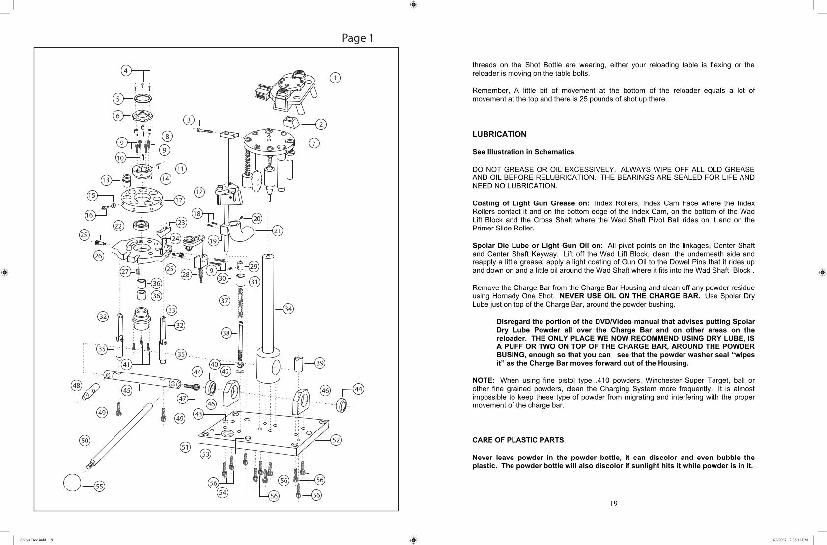
LUBRICATION
See Illustration in Schematics
DO NOT GREASE OR OIL EXCESSIVELY. ALWAYS WIPE OFF ALL OLD GREASE AND OIL BEFORE RELUBRICATION. THE BEARINGS ARE SEALED FOR LIFE AND NEED NO LUBRICATION.
Coating of Light Gun Grease on: Index Rollers, Index Cam Face where the Index Rollers contact it and on the bottom edge of the Index Cam, on the bottom of the Wad Lift Block and the Cross Shaft where the Wad Shaft Pivot Ball rides on it and on the Primer Slide Roller.
Spolar Die Lube or Light Gun Oil on: All pivot points on the linkages, Center Shaft and Center Shaft Keyway. Lift off the Wad Lift Block, clean the underneath side and reapply a little grease; apply a light coating of Gun Oil to the Dowel Pins that it rides up and down on and a little oil around the Wad Shaft where it fits into the Wad Shaft Block .
Remove the Charge Bar from the Charge Bar Housing and clean off any powder residue using Hornady One Shot. NEVER USE OIL ON THE CHARGE BAR. Use Spolar Dry Lube just on top of the Charge Bar, around the powder bushing.
Disregard the portion of the DVD/Video manual that advises putting Spolar Dry Lube Powder all over the Charge Bar and on other areas on the reloader. THE ONLY PLACE WE NOW RECOMMEND USING DRY LUBE, IS A PUFF OR TWO ON TOP OF THE CHARGE BAR, AROUND THE POWDER BUSING, enough so that you can see that the powder washer seal “wipes it” as the Charge Bar moves forward out of the Housing.
NOTE: When using fine pistol type .410 powders, Winchester Super Target, ball or other fine grained powders, clean the Charging System more frequently. It is almost impossible to keep these type of powder from migrating and interfering with the proper movement of the charge bar.
CARE OF PLASTIC PARTS
Never leave powder in the powder bottle, it can discolor and even bubble the plastic. The powder bottle will also discolor if sunlight hits it while powder is in it.
19
Sploar Doc.indd 19 1/2/2007 2:38:31 PM

The clear plastic on your reloader is easy to care for and keep shining like new if you follow just a few simple rules.
If the plastic is dusty or gritty, brush it clean with a soft brush first.
Never use window sprays, kitchen scouring compounds or solvents such as acetone, gasoline, benzene, alcohol, carbon tetrachloride or lacquer thinner.
Hornady One Shot Does a Superb job of keeping all of the plastic clean
IF YOU DO NOT HAVE ONE SHOT:
TO WASH:
Primer Tray Cover, with primers removed, use a clean, damp cloth with dish washing liquid such as Dawn or Joy. Light pressure will do the trick. Rinse with a clean, damp cloth, then blot dry.
Shot and Powder Bottles Drain the contents. Do not remove the plastic Bottles from the Adapters. Wash the Bottles with the Adapters attached in Dish Detergent and Water, rinse, dry and allow to air dry further.
Oops! Fine scratches will disappear when you polish with a good quality plastic buffing compound.
STATIC
In some areas of the country static may cause static cling in the Powder Bottle so that powder sticks to the plastic. The best solution that we have found is to use Compuwipe brand computer cleaner to clean the empty bottle.
MISCELLANEOUS
Periodically check the Shot and Powder Washer Seals for wear and lubricate them with Dry Lube.
Periodically check the bolt in the Handle or hydraulic Stub Handle to be sure that it is tight.
Periodically check that the Shot and Powder Bottles are tight in the threads. A flexing table can work them loose OR wear the threads off the bottles.
20
Gold Premier
Exploded Views and Parts List
Schematic
Sploar Doc.indd 20 1/2/2007 2:38:31 PM
SHOT AND POWDER WASHER SEAL REMOVAL AND REPLACEMENT
REMOVAL: The Shot and Powder Washer Seals are located on the bottom side of the Powder and Shot Adapters, within the Charge Bar Housing. To access the Washer Seals drain both the Shot Bottle and the Powder Bottle one at a time by removing the red plastic plugs from the Shot and Powder Drain Tubes and pushing each Bottle, one at a time to the right, over the respective Drain tubes.
Pull the Charge Bar Cam Pin and Roller and activate the Charge Bar by hand to empty any shot or powder in the Bushings down through the Shot Drop Tube and the Powder Drop Tube. Hold an empty shell under the Drop Tubes to catch the contents of each bushing as it drops. Unscrew the Counter Trip Pin from the front left side of the Charge Bar, hold your hand under the bar to prevent the bushings from dropping out and pull the Charge Bar backward out of the Charge Bar Housing. Use your finger to remove the seals (they should pull right out). Examine the seals for wear, the Powder side is much less likely to wear and can be reused on the shot side. The Seals can also be turned over to the unused side and reinstalled.
REPLACEMENT: Install the new Washer Seals making certain that they fit correctly into the grooves. Apply a puff or two of Dry Lube to the Powder Washer Seal surface. Replace the Charge Bar and Bushings in the Charge Bar Housing but do not reinstall the Charge Bar Cam Pin and Roller yet.
Problems that are evident if the Washer Seals are too tight are: the Bottle Holder will not detent to the On/Off/Drain positions and/or the Charge Bar may not slide back and forth freely when activated by hand. If either of these problems occur loosen the Powder Detent Plunger, the front slotted screw on top of the Charge Bar Cap, slightly until the correct seal is achieved. Make sure after all adjustments are made that the Charge Bar moves back and forth easily by hand.
REPLACING THE PRIMER CUP
1. If the cup has been bent or broken by a primer flipping sideways (see Pre Loading Section of manual for an explanation of why this happens).
2. To replace the damaged Primer Cup remove the spent Primer Box. Move the reloader handle to the forward position. If you are using the manual handle, place a bag of shot of similar weight over the handle to prevent it from slamming back. Use a ½ inch wrench and unscrew the Primer Block Sleeve. Remove the Sleeve together with the Primer Shaft Assembly. Remove the Primer Shaft Assembly form the Sleeve. Hold the primer shaft by the weight and unscrew the Primer Cup Bolt to remove the Primer Cup, be careful not to drop the Spring. Remove the old Primer Cup and Spring. Replace the Spring and install the new Cup, the short, beveled side of the Cup goes up. Pull down on the Cup and Spring until the Cup is shouldered against the Shaft. Tighten the Primer Cup Bolt until it bottoms out.
21
What is happening? What if anything occurred prior to the start of the problem? Did you change wads, primers, hulls or powder? Did you just change gauges? How often is the problem occurring? Did you do something dumb? Please tell us if you did so we know what is really going on.
More often than not we can help you correct the problem over the phone, if can’t we may have you send the problem system to us to check out and repair. If the problem is the result of a part failure, it is covered by the warranty. If it is a problem that not covered by the warranty we will repair, recondition or replace it at a reasonable cost.
Spolar Power Load Incorporated.
2273 South Vista Avenue, B-2
Bloomington, CA 92316-2921
(909) 421-3500
(800) 227-9667
24
Sploar Doc.indd 21 1/2/2007 2:38:31 PM
If the reloader still won’t move:
Make sure that the Turret position is centered over the stations.
If the reloader still won’t move:
Check station #6 for a Primer that did not seat all of the way, the usual cause of this is not making a full stroke with the Handle
The second most common reason is that there is debris between the top surface of the Center Shaft Hub and the bottom of the Bearing Hub. We have even seen flattened pieces of shot stuck on the Gold upper portion of this section.
If a shell bulges or if there is a ring around it, and you can see that it will be impossible to knock out, remove the Die and shell from the knock out station and cut the shell off flush with the Die. Knock the shell out of the Die with a piece of wooden dowel. Reinstall the Die in the Turret. Since you have already indexed to the correct position, pull back on the Index Cam to prevent the machine from indexing again and being out of sequence. Pull the Handle forward, now everything will be dropped properly and you can continue reloading.
If your Spring Fingers start to open up and touch the top of the shells, you can trim them by sanding or clipping as much as 1/16” for extra life.
If you notice at the third station that you missed putting the primer in the shell,you can remove the Die and shell, empty any powder that may be left in it, then carefully insert the Primer almost flush into the shell. Pull the Detent Pin and Roller out of the Charge Bar Cam, deactivating the Charging System. Hold an empty shell or appropriate container under the Shot Drop Tube, push the Charge Bar forward manually and drop the shot. Now, place the shell that missed the primer under the Powder Drop Tube, push the Charge Bar to the rear, charging the shell with powder. Reinstall the Charge Bar Detent Pin and Roller and continue loading.
If the Charge Bar Cam Roller won’t stay on the pin, be sure you have not switched it with the Primer Tray Pin or the Power Load Hydraulic Pin and that you have not installed the Roller backward.
If the Vibrator does not work, first check that the Charge Bar Roller is contacting the Momentary Switch. If it isn’t, the Electrical Switch Box may have moved back slightly, you can pull it out a little. Check the electrical connection then the fuse. Fuse # is 1A 5x20 FA, and is available from either Spolar Power Load or Radio Shack.
If you feel that the reloader has become hard to move and suspect the Charge Bar,make certain that you have not installed a bush that is too long. Bushings should not be higher than the Charge Bar or they will hit the Charge Bar Housing.
Technical Support
When you call for technical support, be prepared to tell us the following:
23
3. Clean the inside of the Sleeve and the Shaft with Hornady One Shot. Replace the Shaft into the Sleeve and screw the Sleeve back into the Primer Block. BE CAREFULLY WHEN TIGHTENING THE SLEEVE, THE THREADED PORTION IS VERY THIN
TROUBLE SHOOTING
The majority of calls we receive about reloader problems are ultimately resolved by locating shot or other debris in critical areas of the reloader. If you are having a problem with primers in the Primer System, look for shot in the Primer Track, Primer Feed, Primer Cup, Primer Shaft Sleeve or wherever the problem is apparent.
If the primers consistently not feeding into the cup and the Primer Track is full, STOP RELOADING. Remove all of the dies and with the hulls in them from the reloader, empty the Shot and Powder Bushings and /or disarm the Shot and Powder Charging system by pulling the Charge Bar Cam Pin and Roller.
Clean up any spilled shot and powder, then start operating the reloader, feeding primers and removing them from the primer cup with a magnet, feed another one remove it with a magnet, keep repeating and watching to see exactly what is happening. 99 times out of 100, the problem is shot in the track. It is usually about 2 or 3 inches above where the track is connected to the Male Primer Feed, back under the folds of the track.
If you are having problems with the Primer seating fully in the shell, check to be sure that there is no shot or other debris between the Center Shaft Hub and the Bearing Hub, preventing the Hubs from making tight contact (Figure 19A), or that there is no debris preventing the Handle from making a full stroke or that the Handle is not loose.
The Majority of the components feeding problems we encounter have been the result of foreign objects. The number one problem has been string from shot sacks. We have helped locate everything from snack food to primers that were accidentally swept up with spilled powder and put back in the Powder and Shot Bottles. Foreign objects in hulls can block the powder drop tube, or interfere with seating the wad.
If the reloader won’t move:
Check that there is not a shell hung in the knock out position.
If the reloader still won’t move
Turn each of the Dies individually by hand; the Die that won’t turn is the problem. Remove the Die from the Turret and either correct the shell problem or push the shell out of the Die by hand. If the shot and powder has already dropped you can reinstall the Die and the Turret in continue loading with the Die temporarily empty. If the shot and/or powder has not been dropped; put an empty shell in the Die and catch the charges, one at a time, in the empty shell and dispose of the charges. Do not use the Wad Arm to hold an empty shell to catch the shot charge. Doing so will break the Wad Arm.
22
Sploar Doc.indd 22 1/2/2007 2:38:31 PM