Embed Size (px)
Citation preview

Steel Frame Design Manual AASHTO LRFD 2007

Steel Frame
Design Manual AASHTO LRFD 2007
For CSiBridge®
ISO BRG102816M25 Rev. 0 Proudly developed in the United States of America October 2016

Copyright
Copyright Computers and Structures, Inc., 1978-2016 All rights reserved. The CSI Logo® and CSiBridge® are registered trademarks of Computers and Structures, Inc. Watch & LearnTM is a trademark of Computers and Structures, Inc. The computer program CSiBridge® and all associated documentation are proprietary and copyrighted products. Worldwide rights of ownership rest with Computers and Structures, Inc. Unlicensed use of these programs or reproduction of documentation in any form, without prior written authorization from Computers and Structures, Inc., is explicitly prohibited.
No part of this publication may be reproduced or distributed in any form or by any means, or stored in a database or retrieval system, without the prior explicit written permission of the publisher.
Further information and copies of this documentation may be obtained from:
Computers and Structures, Inc. www.csiamerica.com [email protected] (for general information) [email protected] (for technical support)
DISCLAIMER
CONSIDERABLE TIME, EFFORT AND EXPENSE HAVE GONE INTO THE DEVELOPMENT AND TESTING OF THIS SOFTWARE. HOWEVER, THE USER ACCEPTS AND UNDERSTANDS THAT NO WARRANTY IS EXPRESSED OR IMPLIED BY THE DEVELOPERS OR THE DISTRIBUTORS ON THE ACCURACY OR THE RELIABILITY OF THIS PRODUCT.
THIS PRODUCT IS A PRACTICAL AND POWERFUL TOOL FOR STRUCTURAL DESIGN. HOWEVER, THE USER MUST EXPLICITLY UNDERSTAND THE BASIC ASSUMPTIONS OF THE SOFTWARE MODELING, ANALYSIS, AND DESIGN ALGORITHMS AND COMPENSATE FOR THE ASPECTS THAT ARE NOT ADDRESSED.
THE INFORMATION PRODUCED BY THE SOFTWARE MUST BE CHECKED BY A QUALIFIED AND EXPERIENCED ENGINEER. THE ENGINEER MUST INDEPENDENTLY VERIFY THE RESULTS AND TAKE PROFESSIONAL RESPONSIBILITY FOR THE INFORMATION THAT IS USED.
Contents
1 Introduction
1.1 Organization 1-2
1.2 Recommended Reading/Practice 1-3
2 Modeling, Analysis and Design Prerequisites
2.1 Check and Design Capability 2-1
2.2 Analysis Sections vs. Design Sections 2-2
2.3 Design and Check Stations 2-3
2.4 Demand/Capacity Ratios 2-4
2.5 Design Load Combinations 2-5
2.6 Second Order P-Delta Effects 2-6
2.7 Member Unsupported Lengths 2-8
2.8 Effective Length Factor (K) 2-10
2.9 Effects of Breaking a Member into Multiple Elements 2-13
2.10 Supported Framing Types 2-14
2.11 Frame Design Procedure Overwrites 2-15
Contents - i
Steel Frame Design AASHTO 2007
2.12 Steel Frame Design Process 2-15
2.13 Interactive Steel Frame Design 2-18
2.14 Choice of Unites 2-18
3 Check/Design for AASHTO LRFD 07
3.1 Notations 3-2
3.2 Design Preferences 3-5
3.3 Design Overwrites 3-7
3.4 Design Loading Combinations 3-10
3.5 Classification of Sections for Local Buckling 3-11
3.6 Calculation of Factored Forces and Moments 3-19
3.7 Calculation of Nominal Strengths 3-21 3.7.1 Tension Resistance 3-22 3.7.2 Compression Resistance 3-23 3.7.3 Flexure Resistance 3-34 3.7.4 Shear Resistance 3-64
3.8 Calculation of Capacity Ratios for Combined Forces 3-69 3.8.1 Members Subjected to Flexure and Axial Tension 3-69 3.8.2 Members Subjected to Flexure and Axial Compression 3-71 3.8.3 Members Subjected to Shear Force 3-73
4 Design Output
4.1 Overview 4-1
4.2 Display Design Information on the Model 4-2
4.3 Display Design Information in Tables 4-4
4.4 Display Detailed Member Specific Information 4-8
4.5 Output of Design Information 4-13
4.6 Error Messages and Warnings 4-15
Bibliography
Appendix A Steel Frame Design Preferences
ii - Contents

Contents
Appendix B Frame Design Procedure Overwrites
Contents - iii
Chapter 1 Introduction
The design/check of steel frames is seamlessly integrated within the program. Initiation of the design process, along with control of various design parame-ters, is accomplished using the Advanced > Frame Design commands.
It should be noted that two design processes are available in CSiBridge: super-structure design (on the Design/Rating tab) and design of the individual ele-ments comprising the structure (the Advanced > Frame Design commands). This manual addresses the second design process.
Automated design at the object level is available for any one of a number of user-selected design codes, as long as the structures have first been modeled and analyzed by the program. Model and analysis data, such as material prop-erties and member forces, are recovered directly from the model database, and are used in the design process in accordance with the user defined or default design settings. As with all design applications, the user should carefully re-view all of the user options and default settings to ensure that the design pro-cess is consistent with the user’s expectations.
The design is based on a set of user-specified loading combinations. Although the program provides default load combinations for most of the supported de-sign codes, it does not generate a set of default load combinations for AASH-
1 - 1
Steel Frame Design AASHTO LRFD 2007
TO LRFD 2007 design code. The user is responsible for generating the design load combinations as needed.
Steel frame design/check consists of calculating the flexural, axial, and shear forces or stresses at several locations along the length of a member, and then comparing those calculated values with acceptable limits. That comparison produces a demand/capacity ratio, which typically should not exceed a value of one if code requirements are to be satisfied. The program follows the same re-view procedures when it is checking a user-specified shape or when checking a shape selected by the program from a predefined list.
Program output can be presented graphically on the model, in tables for both input and output data, or in calculation sheets prepared for each member. For each presentation method, the output is in a format that allows the engineer to quickly study the stress conditions that exist in the structure, and in the event the member is not adequate, aid the engineer in taking appropriate remedial measures, including altering the design member without re-running the entire analysis.
The program supports a wide range of steel frame design codes, including many national codes. This manual is dedicated to the use of the menu option "AASHTO LRFD 2007." This option covers the LRFD design provisions, in-cluding 2008 interim revisions.
The design codes supported under “AASHTO LRFD 2007” are written in kip-inch units. All the associated equations and requirements have been imple-mented in the program in kip-inch units. The program has been enabled with unit conversion capability. This allows the users to enjoy the flexibility of choosing any set of consistent units during creating and editing models, export-ing and importing the model components, and reviewing the design results.
1.1 Organization This manual is designed to help you quickly become productive using the AASHTO LRFD 2007 steel frame design option. Chapter 2 addresses prereq-uisites related to modeling and analysis for a successful design in accordance with AASHTO LRFD 2007. Chapter 3 provides detailed descriptions of the
1 - 2 Organization
Chapter 1 - Introduction
specific requirements as implemented in AASHTO LRFD 2007. Chapter 4 concludes by illustrating some of the display and output options.
1.2 Recommended Reading/Practice It is strongly recommended that you read this manual and review any applica-ble "Watch & Learn" SeriesTM tutorials, which are found on our web site, http://www.csiamerica.com, before attempting to design a steel frame. Addi-tional information can be found in the on-line Help facility available from within the program.
Recommended Reading/Practice 1 - 3
Chapter 2 Modeling, Analysis and Design Prerequisites
This chapter provides an overview of the basic assumptions, design precondi-tions, and some of the design parameters that affect the design of steel frames.
For referring to pertinent sections of the corresponding code, a unique prefix is assigned for each code.
• Reference to the AASHTO LRFD 2007 code is identified with the prefix "AASHTO."
• Reference to the 1999 AISC LRFD code is identified with the prefix "AISC99."
• Reference to ANSI/AISC 360-05 code is identified with the prefix "AISC05."
2.1 Check and Design Capability The program has the ability to check the adequacy of a section (shape) in ac-cordance with the requirements of the selected design code. Also the program can automatically choose (i.e., design) the optimal (i.e., least weight) sections from a predefined list that satisfies the design requirements.
2 - 1
Steel Frame Design AASHTO LRFD 2007
To check adequacy of a section, the program checks the demand/capacity (D/C) ratios at a predefined number of stations for each design load combina-tion. It calculates the envelope of the D/C ratios. It also checks the other requirements on a pass or fail basis. If the capacity ratio remains less than or equal to the D/C ratio limit, which is a number close to 1.0, and if the section passes all of the special requirements, the section is considered to be adequate, else the section is considered to be failed. The D/C ratio limit is taken as 0.95 by default. However, this value can be overwritten in the Preferences (Chapter 3).
To choose (design) the optional section from a predefined list, the program first orders the list of sections in increasing order of weight per unit length. Then it starts checking each section from the ordered list, starting with the one with the least weight. The procedure for checking each section in this list for adequacy is exactly the same as described in the preceding paragraph. The program will evaluate each section in the list until it finds the least weight section that passes the code checks. If no section in the list is acceptable, the program will use the heaviest section but flag it as being overstressed.
To check adequacy of an individual section, the user must assign the section using the Advanced > Assign menu. In that case, both the analysis and design section will be changed.
To choose the optimal section, the user must first define a list of steel sections, the Auto Select sections list. The user must next assign this list, in the same manner as any other section assignment, to the frame members to be optimized. The program will use the median section by weight when doing the initial analysis. Click the Components > Type > Frame Properties > New com-mand to access the Add Frame Section Property form and add an Auto Select sections list to the model file.
2.2 Analysis Sections vs. Design Sections Analysis sections are those section properties used to analyze the model when the Analysis > Analyze > Run Analysis command is clicked. The design sec-tion is whatever section is used in the steel frame design. It is possible for the last used analysis section and the current design section to be different. For ex-ample, an analysis may be run using a W18X35 beam, and then in the design, it
2 - 2 Analysis Sections vs. Design Sections
Chapter 2 - Modeling, Analysis and Design Prerequisites
may be found that a W16X31 beam worked. In that case, the last used analysis section is the W18X35 and the current design section is the W16X31. Before the design process is complete, verify that the last used analysis section and the current design section are the same. The Advanced > Frame Design > Steel > Verify Analysis vs Design Section command is useful for this task.
The program keeps track of the analysis section and the design section sepa-rately. Note the following about analysis and design sections:
Assigning a frame section property using the Advanced > Assign > Frames > Frame Sections command assigns the section as both the analy-sis section and the design section.
Running an analysis using the Analysis > Analyze > Run Analysis com-mand always sets the analysis section to be the same as the current design section.
Assigning an Auto Select section list to a frame object initially sets the analysis and design section to be the section in the list with the median weight.
Unlocking a model deletes the design results, but it does not delete or change the design section.
Altering the Design Combinations in any way deletes the design results, but does not delete or change the design section.
Altering any of the steel frame design preferences deletes the design re-sults, but does not delete or change the design section.
2.3 Design and Check Stations For each design combination, steel frame members (beams, columns, and brac-es) are designed (optimized) or checked at a number of locations (stations) along the length of the object. The stations are located at equally spaced seg-ments along the clear length of the object. By default, at least three stations will be located in a column or brace member, and the stations in a beam will be spaced at most 2 feet apart (0.5 m if the model has been created in Metric units). The user can overwrite the number of stations in an object before the
Design and Check Stations 2 - 3
Steel Frame Design AASHTO LRFD 2007
analysis is made using the Advanced > Assign commands. The user can refine the design along the length of a member by requesting more stations.
2.4 Demand/Capacity Ratios Determination of the controlling D/C ratios for each steel frame member indi-cates the acceptability of the member for the given loading conditions. The steps for calculating the D/C ratios are as follows:
The factored forces are calculated for axial, flexural, and shear at each de-fined station for each design combination. The bending moments are calcu-lated about the principal axes. For I-Shape, Box, Channel, T-Shape, Dou-ble-Angle, Pipe, Circular, and Rectangular sections, the principal axes co-incide with the geometric axes. For Single-Angle sections, the design con-siders the principal properties. For General sections, it is assumed that all section properties are given in terms of the principal directions.
For Single-Angle sections, the shear forces are calculated for directions along the geometric axes. For all other sections, the program calculates the shear forces along the geometric and principal axes.
The design strengths are calculated for compression, tension, bending and shear based on the equations provided later in this manual. For flexure, the nominal strengths are calculated based on the principal axes of bending. For the I-Shape, Box, Channel, Circular, Pipe, T-Shape, Double-Angle and Rectangular sections, the principal axes coincide with their geometric axes. For the Angle sections, the principal axes are determined and all computa-tions related to flexural stresses are based on that.
The design strength for shear is calculated along the geometric axes for all sections. For I-Shape, Box, Channel, T-Shape, Double-Angle, Pipe, Circu-lar, and Rectangular sections, the principal axes coincide with their geo-metric axes. For Single-Angle sections, principal axes do not coincide with the geometric axes.
Factored forces are compared to design strengths to determine D/C ratios. In either case, design codes typically require that the ratios not exceed a value of one. A capacity ratio greater than one indicates a member that has exceeded a limit state.
2 - 4 Demand/Capacity Ratios
Chapter 2 - Modeling, Analysis and Design Prerequisites
2.5 Design Load Combinations The design load combinations are the various combinations of the prescribed load cases for which the structure needs to be checked. The program does not create a number of default design load combinations for steel frame design for the AASHTO LRFD 2007 code. Users should add their own design combina-tions. An unlimited number of load combinations can be specified.
To define a design load combination, simply specify one or more load cases, each with its own scale factor. The scale factors are applied to the forces and moments from the load cases to form the factored design forces and moments for each load combination.
There are many types of dead loads (DL), including dead load of structural components and nonstructural attachments (DC), downdrag (DD), dead load of wearing surface and utilities (DW), horizontal earth pressure load (EH), verti-cal earth pressure load (EV), and earth surcharge load (ES). Each type of dead load pattern requires a separate load factor (AASHTO 3.4.1).
There are many types of live loads (LL), including vehicular live load (LL), vehicular dynamic load allowance (IM), vehicular centrifugal force (CE), ve-hicular braking force (BR), pedestrian live load (PL), and live load surcharge (LS). All these live load patterns require the same factor and do not need to be treated separately (AASHTO 3.4.1).
If the structure is subjected to structural dead load (DL), live load (LL), wind load (WL), and earthquake loads (EL), and considering that wind and earth-quake forces are reversible, the user should create load combinations to be con-sidered for Strength and Extreme Event limit states (AASHTO 3.4.1).
For other loading conditions involving vehicular moving load, time history, pattern live load, snow load, friction, temperature, buoyancy, ice, collision, no-tional load, and the like, the user must define the load combinations.
For multi-valued design combinations, such as those involving response spec-trum, time history, moving loads and envelopes, where any correspondence between forces is lost, the program automatically produces sub-combinations using the maxima/minima values of the interacting forces. Separate combina-tions with negative factors for response spectrum load cases are not required because the program automatically takes the minima to be the nega-
Design Load Combinations 2 - 5
Steel Frame Design AASHTO LRFD 2007
tive of the maxima response when preparing the sub-combinations described previously.
The program allows live load reduction factors to be applied to the member forces of the reducible live load pattern on a member-by-member basis to re-duce the contribution of the live load to the factored responses.
2.6 Second Order P-Delta Effects Modern design provisions are based on the principle that the member forces are calculated by a second-order elastic analysis, where the equilibrium is satisfied on the deformed geometry of the structure. The effects of the loads acting on the deformed geometry of the structure are known as the second-order or the P-Delta effects.
The P-Delta effects come from two sources: global lateral translation of the frame and the local deformation of members within the frame.
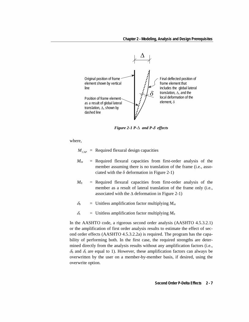
Consider the frame object shown in Figure 2-1, which is extracted from a level of a larger structure. The overall global translation of this frame object is indi-cated by ∆. The local deformation of the member is shown as δ. The total sec-ond order P-Delta effects on this frame object are those caused by both ∆ and δ.
The program has an option to consider P-Delta effects in the analysis. When you consider P-Delta effects in the analysis, the program does a good job of capturing the effect due to the ∆ deformation (P-∆ effect) shown in Figure 2-1, but it does not typically capture the effect of the δ deformation (P-δ effect), unless, in the model, the frame object is broken into multiple elements over its length.
In design codes, required strengths are usually required to be determined using a second-order analysis that considers both P-∆ and P-δ effects. Approximate second-order analysis procedures based on amplification of responses from first-order analysis for calculating the required flexural and axial strengths are common in current design codes and have the following general form:
= +CAP b nt s ltM M Mδ δ (AASHTO 4.5.3.2.2b)
2 - 6 Second Order P-Delta Effects
Chapter 2 - Modeling, Analysis and Design Prerequisites
∆
δ
Original position of frameelement shown by verticalline
Position of frame elementas a result of global lateraltranslation, ∆, shown bydashed line
Final deflected position offrame element thatincludes the global lateraltranslation, ∆, and thelocal deformation of theelement, δ
Figure 2-1 P-∆ and P-δ effects
where,
CAPM = Required flexural design capacities
Mnt = Required flexural capacities from first-order analysis of the member assuming there is no translation of the frame (i.e., asso-ciated with the δ deformation in Figure 2-1)
Mlt = Required flexural capacities from first-order analysis of the member as a result of lateral translation of the frame only (i.e., associated with the ∆ deformation in Figure 2-1)
δb = Unitless amplification factor multiplying Mnt
δs = Unitless amplification factor multiplying Mlt
In the AASHTO code, a rigorous second order analysis (AASHTO 4.5.3.2.1) or the amplification of first order analysis results to estimate the effect of sec-ond order effects (AASHTO 4.5.3.2.2a) is required. The program has the capa-bility of performing both. In the first case, the required strengths are deter-mined directly from the analysis results without any amplification factors (i.e., δb and δs are equal to 1). However, these amplification factors can always be overwritten by the user on a member-by-member basis, if desired, using the overwrite option.
Second Order P-Delta Effects 2 - 7
Steel Frame Design AASHTO LRFD 2007
To properly capture the P-δ effect in a finite element analysis, each element, especially column elements, must be broken into multiple finite elements, which is not really desired for other reasons. Although a single element per member can capture the P-δ effect to some extent, the program considers that inadequate. The program thus uses the δb factor even if the analysis considers the P-∆ effects. This is a conservative approach.
Thus, in general, the steel frame design feature requires consideration of P-Delta effects in the analysis before the check/design is performed. Although one element per line object is generally adequate to capture the P-∆ effect, it is recommended to use more than one element per line object for the cases where both P-∆ and P-δ effects are to be considered. However, explicit manual break-ing of the member into elements has other consequences related to member end moments and unbraced segment end moment. It is recommended that the members be broken internally by the program. In this way, the member is recognized as one unit, end of the members are identified properly, and P-∆ and P-δ effects are captured better.
2.7 Member Unsupported Lengths The column unsupported lengths are required to account for column slender-ness effects for flexural buckling and for lateral-torsional buckling. The pro-gram automatically determines the unsupported length ratios, which are speci-fied as a fraction of the frame object length. Those ratios times the frame ob-ject lengths give the unbraced lengths for the member. Those ratios also can be overwritten by the user on a member-by-member basis, if desired, using the de-sign overwrite option.
The unsupported length for minor direction bending or for lateral-torsional buckling also can be defined more precisely by using precise bracing points in the Lateral Bracing option, which is accessed using the Advanced > Frame Design > More > Lateral Bracing command. This allows the user to define the lateral bracing of the top, bottom, or both flanges. The bracing can be a point brace, or continuous bracing is considered enough for flexural buckling in the minor direction. The unbraced length of the compression flange is de-termined based on the current moment diagram to determine the lateral-torsional buckling length, LLTB. This exact method of bracing definition does not allow the user to define unbraced lengths for major direction bending.
2 - 8 Member Unsupported Lengths
Chapter 2 - Modeling, Analysis and Design Prerequisites
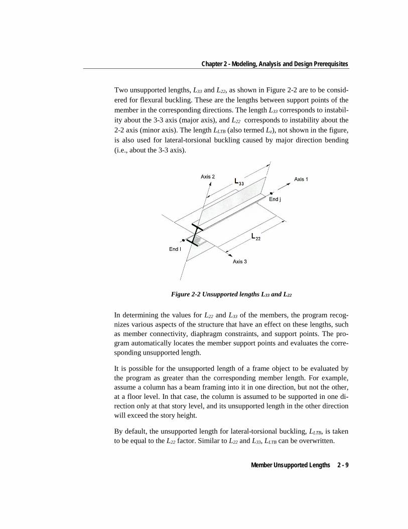
Two unsupported lengths, L33 and L22, as shown in Figure 2-2 are to be consid-ered for flexural buckling. These are the lengths between support points of the member in the corresponding directions. The length L33 corresponds to instabil-ity about the 3-3 axis (major axis), and L22 corresponds to instability about the 2-2 axis (minor axis). The length LLTB (also termed Lz), not shown in the figure, is also used for lateral-torsional buckling caused by major direction bending (i.e., about the 3-3 axis).
Figure 2-2 Unsupported lengths L33 and L22
In determining the values for L22 and L33 of the members, the program recog-nizes various aspects of the structure that have an effect on these lengths, such as member connectivity, diaphragm constraints, and support points. The pro-gram automatically locates the member support points and evaluates the corre-sponding unsupported length.
It is possible for the unsupported length of a frame object to be evaluated by the program as greater than the corresponding member length. For example, assume a column has a beam framing into it in one direction, but not the other, at a floor level. In that case, the column is assumed to be supported in one di-rection only at that story level, and its unsupported length in the other direction will exceed the story height.
By default, the unsupported length for lateral-torsional buckling, LLTB, is taken to be equal to the L22 factor. Similar to L22 and L33, LLTB can be overwritten.
Member Unsupported Lengths 2 - 9
Steel Frame Design AASHTO LRFD 2007
2.8 Effective Length Factor (K) The effective length method for calculating member axial compressive strength has been used in various forms in several stability based design codes. The method originates from calculating effective buckling lengths, KL, and is based on elastic/inelastic stability theory. The effective buckling length is used to cal-culate an axial compressive strength, Pn, through an empirical column curve that accounts for geometric imperfections, distributed yielding, and residual stresses present in the cross-section.
There are two types of K-factors in the AASHTO LRFD 2007 code. The first type of K-factor is used for calculating the Euler axial capacity assuming that all of the member joints are held in place, i.e., no lateral translation is allowed. The resulting axial capacity is used in calculation of the δb factor. This K-factor is named as K1 in this document. This K1 factor is always less than 1 and is not calculated. By default the program uses the value of 1 for K1. The program al-lows the user to overwrite K1 on a member-by-member basis.
The other K-factor is used for calculating the Euler axial capacity assuming that all the member joints are free to sway, i.e., lateral translation is allowed. The resulting axial capacity is used in calculating Pn. This K-factor is named as K2 in this document. This K2 is always greater than 1 if the frame is a sway frame. The program calculates the K2 factor automatically based on sway con-dition. The program also allows the user to overwrite K2 factors on a member-by-member basis. The same K2 factor is supposed to be used in calculation of the δs factor. However the program does not calculate δs factors and relies on the overwritten values. If the frame is not really a sway frame, the user should overwrite the K2 factors.
Both K1 and K2 have two values: one for major direction and the other for mi-nor direction, K1minor, K1major, K2minor, K2major.
There is another K-factor. Kltb for lateral torsional buckling. By default, Kltb is taken as equal to K2minor. However the user can overwrite this on a member-by-member basis.
The rest of this section is dedicated to the determination of K2 factors.
The K-factor algorithm has been developed for building-type structures, where the columns are vertical and the beams are horizontal, and the behavior is basi-
2 - 10 Effective Length Factor (K)
Chapter 2 - Modeling, Analysis and Design Prerequisites
cally that of a moment-resisting frame for which the K-factor calculation is rel-atively complex. For the purpose of calculating K-factors, the objects are iden-tified as columns, beams, and braces. All frame objects parallel to the Z-axis are classified as columns. All objects parallel to the X-Y plane are classified as beams. The remainders are considered to be braces.
The beams and braces are assigned K-factors of unity. In the calculation of the K-factors for a column object, the program first makes the following four stiff-ness summations for each joint in the structural model:
= ∑ c c
cxc x
E ISL
b bbx
b x
E ISL
= ∑
c ccy
c y
E ISL
= ∑ b b
b yb y
E ISL
= ∑
where the x and y subscripts correspond to the global X and Y directions and the c and b subscripts refer to column and beam. The local 2-2 and 3-3 terms
22 22EI L and 33 33EI L are rotated to give components along the global X and Y directions to form the ( )x
EI L and ( )yEI L values. Then for each column,
the joint summations at END-I and the END-J of the member are transformed back to the column local 1-2-3 coordinate system, and the G-values for END-I and the END-J of the member are calculated about the 2-2 and 3-3 directions as follows:
22
2222
bI
cI
I
SSG =
22
2222
bJ
cJ
J
SSG =
33
3333
bI
cI
I
SSG =
33
3333
bJ
cJ
J
SSG =
If a rotational release exists at a particular end (and direction) of an object, the corresponding value of G is set to 10.0. If all degrees of freedom for a particu-lar joint are deleted, the G-values for all members connecting to that joint will be set to 1.0 for the end of the member connecting to that joint. Finally, if IG and JG are known for a particular direction, the column K-factor for the corre-sponding direction is calculated by solving the following relationship for α:
Effective Length Factor (K) 2 - 11
Steel Frame Design AASHTO LRFD 2007
ααα
tan)(6362
=+
−JI
JI
GGGG (AASHTO C4.6.2.5-2)
from which K = π/α. This relationship is the mathematical formulation for the evaluation of K-factors for moment-resisting frames assuming sidesway to be uninhibited. For other structures, such as braced frame structures, the K-factors for all members are usually unity and should be set so by the user. The follow-ing are some important aspects associated with the column K-factor algorithm:
An object that has a pin at the joint under consideration will not enter the stiffness summations calculated previously. An object that has a pin at the far end from the joint under consideration will contribute only 50% of the calculated EI value. Also, beam members that have no column member at the far end from the joint under consideration, such as cantilevers, will not enter the stiffness summation.
If there are no beams framing into a particular direction of a column mem-ber, the associated G-value will be infinity. If the G-value at any one end of a column for a particular direction is infinity, the K-factor corresponding to that direction is set equal to unity.
If rotational releases exist at both ends of an object for a particular direc-tion, the corresponding K-factor is set to unity.
The automated K-factor calculation procedure occasionally can generate artificially high K-factors, specifically under circumstances involving skewed beams, fixed support conditions, and under other conditions where the program may have difficulty recognizing that the members are laterally supported and K-factors of unity are to be used.
All K-factor produced by the program can be overwritten by the user. These values should be reviewed and any unacceptable values should be replaced.
The beams and braces are assigned K-factors of unity.
2 - 12 Effective Length Factor (K)
Chapter 2 - Modeling, Analysis and Design Prerequisites
2.9 Effects of Breaking a Member into Multiple Elements The preferred method is to model a beam, column or brace member as one sin-gle element. However, the user can request that the program break a member internally at framing intersections and at specified intervals. In this way, accu-racy in modeling can be maintained at the same time that design/check specifi-cations can be applied accurately. There is special emphasis on the end forces (moments in particular) for many different aspects of beam, column, and brace design. If the member is manually meshed (broken) into segments, maintaining the integrity of the design algorithm becomes difficult.
Manually breaking a column member into several elements can affect many things during design in the program.
1. The unbraced length: The unbraced length is really the unsupported length between braces. If no intermediate brace is present in the member, the un-braced length is typically calculated automatically by the program from the top of the flange of the beam framing the column at the bottom to the bot-tom of the flange of the beam framing the column at the top. The automati-cally calculated length factor typically becomes less than 1. If there are in-termediate bracing points, the user should overwrite the unbraced length factor in the program. The user should choose the critical (larger) one. Even if the user breaks the element, the program typically picks up the un-braced length correctly, provided that there is no intermediate bracing point.
2. K-factor: Even if the user breaks the member into pieces, the program typi-cally can pick up the K-factors correctly. However, sometimes it can not. The user should note the K-factors. All segments of the member should have the same K-factor and that factor should be calculated based on the entire member. If the calculated K-factor is not reasonable, the user can overwrite the K-factors for all the segments.
3. Cm factor: The Cm factor should be based on the end moments of unbraced lengths of each segment and should not be based on the end moments of the member. The program already calculates the Cm factors based on the end moments of unbraced lengths of each segment. If the break-up points are the brace points, no action is required by the user. If the broken seg-ments do not represent the brace-to-brace unsupported length, the program
Effects of Breaking a Member into Multiple Elements 2 - 13
Steel Frame Design AASHTO LRFD 2007
calculated Cm factor is conservative. If this conservative value is accepta-ble, no action is required by the user. If it is not acceptable, the user can calculate the Cm factor manually for the critical combination and overwrite its value for that segment.
4. Cb factor: The logic is similar to that for the Cm factor.
5. δb factor: This factor amplifies the factored moments for the P-δ effect. In its expression, there are the Cm factor and the Euler Buckling capacity Pe. If the user keeps the unbraced length ratios (L33 and L22) and the K-factors (K33 and K22) correct, the δb factor would be correct. If the axial force is small, the δb factor can be 1 and have no effect with respect to modeling the single segment or multi-segment element.
6. δs factor: The program does not calculate the δs factor. The program as-sumes that the user turns on the P-∆. In such cases, δs can be taken as equal to 1. That means the modeling with one or multiple segments has no effect on this factor.
If the user models a column with a single element and makes sure that the L-factors and K-factors are correct, the effect of δb and δs will be picked up cor-rectly. The factors Cm and Cb will be picked up correctly if there is no interme-diate bracing point. The calculated Cm and Cb factors will be slightly conserva-tive if there are intermediate bracing points.
If the user models a column with multiple elements and makes sure that L-factors and K-factors are correct, the effect of δb and δs will be picked up cor-rectly. The factors Cm and Cb will be picked up correctly if the member is bro-ken at the bracing points. The calculated Cm and Cb factors will be conservative if the member is not broken at the bracing points.
2.10 Supported Framing Types The code recognizes the following types of framing systems.
Moment Frame
Braced Frame
2 - 14 Supported Framing Types
Chapter 2 - Modeling, Analysis and Design Prerequisites
2.11 Frame Design Procedure Overwrites The structural model may contain frame elements made of several structural materials: steel, concrete, aluminum, cold-formed steel and other materials. The program supports separate design procedures for each material type. By default the program determines the design procedure from the material of the frame member.
The program allows the user to turn the design of specific members off and on by selecting No Design or Default from material. Overwriting the design pro-cedure can be completed using the Advanced > Frame Design > More > Overwrite Frame Design Procedure command.
A change in design will be successful only if the design procedure is valid for that member, i.e., the program will not allow the user to change the design pro-cedure for a steel frame object to concrete frame design.
2.12 Steel Frame Design Process The following sequence describes a typical steel frame design process for the individual elements comprising the structure (i.e., using the Advanced > Frame Design commands; superstructure design is described in the Bridge Su-perstructure Design manual and the Bridge Seismic Design manual). Note that although the sequence of steps you follow may vary, the basic process proba-bly will be essentially the same.
1. Use the Advanced > Frame Design > Steel > View/Revise Overwrites command to choose the steel frame design code and to review other steel frame design preferences and revise them if necessary. Note that default values are provided for all design preferences, so it is unnecessary to define any preferences unless you want to change some of the default values.
2. Create the model.
3. Run the analysis using the Analysis > Analyze > Run Analysis command.
4. Assign steel frame overwrites, if needed, using the Advanced > Frame Design > Steel > View/Revise Overwrites command. Note that frame
Frame Design Procedure Overwrites 2 - 15
Steel Frame Design AASHTO LRFD 2007
members must be selected before using this command, and that overwrites may be assigned before or after the analysis is run.
5. Designate design groups, if desired, using the Advanced > Frame Design > Steel > Select Design Group command. Note that some groups must al-ready have been created by selecting objects and going to the Assign menu.
6. To use design combinations other than the defaults created by the program, click the Advanced > Frame Design > Steel > Select Design Combo command. Note that design combos must already have been created using the Design/Rating > Load Combinations commands.
7. Designate displacement targets for various analysis cases using the Ad-vanced > Frame Design > Steel > Set Displacement Targets command.
8. Set time period targets for various modes using the Advanced > Frame Design > Steel > Set Time Period Targets command.
9. Click the Advanced > Frame Design > Steel > Start Design/Check of Structure command to run the steel frame design.
10. Review the steel frame design results by doing one of the following:
a. Click the Advanced > Frame Design > Steel > Display Design In-formation command to display design input and output information on the model.
b. Right click on a frame object while the design results are displayed on it to enter the interactive design mode and interactively design the frame member. Note that while in this mode, overwrites can be revised and the results of the new design displayed immediately. If design results are not currently displayed (and the design has been run), click the Advanced > Frame Design > Steel > Interactive Steel Frame Design command and then right click a frame object to enter the interactive design mode for the member.
11. Use the File > Print > Print Tables command to print steel frame design data. If frame objects are selected before using this command, data is print-ed for the selected objects only.
2 - 16 Steel Frame Design Process
Chapter 2 - Modeling, Analysis and Design Prerequisites
12. Use the Home > Display > Show Tables command to display steel frame design data in a spreadsheet-type tabular format. If frame objects are se-lected before using the command, data is displayed for the selected objects only.
13. Use the Advanced > Frame Design > Steel > Change Design Section command to change the design section properties for selected frame ob-jects.
14. Click the Advanced > Frame Design > Steel > Start Design/Check of Structure command to rerun the design with the new section properties. Review the results using the procedures described in Item 10.
15. Rerun the analysis using the Analysis > Analyze > Run Analysis com-mand. Note that the section properties used for the analysis are the last specified design section properties.
16. Compare displacements with displacement targets, or the resulting periods with period targets, if appropriate.
17. Click the Advanced > Frame Design > Steel > Start Design/Check of Structure command to rerun the design with the new analysis results. Re-view the results using the previous steps.
18. Repeat the processes in steps 13 through 17 as many times as necessary. Note that steel frame design is an iterative process, and that the analysis and design will typically be rerun multiple times to complete a design.
19. Click the Advanced > Frame Design > Steel > Verify Analysis vs Design Section command to verify that all of the final design sections are the same as the last used analysis sections.
Again, it is important to note that design is an iterative process. The sections used in the original analysis are not likely to be the same as those obtained at the end of the design process. Always run the analysis using the frame sections from the final design, and then run a design check using the forces obtained from that analysis.
Steel Frame Design Process 2 - 17
Steel Frame Design AASHTO LRFD 2007
2.13 Interactive Steel Frame Design The Interactive Steel Frame Design command is a powerful mode that allows the user to review the design results for any steel frame design and interactive-ly revise the design assumptions and immediately review the revised results.
Note that a design must have been run for the interactive design mode to be available. With the design results displayed, right click on a frame object to display the Steel Stress Check Information form for the member. Click on the Overwrites button to display the Design Overwrites form, where the member section or other design parameters may be changed. Clicking OK on this form results in an immediate updating of the results displayed on the Steel Stress Check Information form.
2.14 Choice of Units English as well as SI and MKS metric units can be used for input. The codes are based on a specific system of units. All equations and descriptions present-ed in the subsequent chapters correspond to that specific system of units unless otherwise noted. For example, the AASHTO LRFD 2007 code is published in kips-inch-second units. By default, all equations and descriptions presented in this document correspond to kips-inch-second units. However, any system of units can be used to define and design a structure in the program.
2 - 18 Interactive Steel Frame Design
Chapter 3 Check/Design Using AASHTO LRFD 07
This chapter describes the details of the structural steel design and stress check algorithms that are used by CSiBridge when the user selects the “AASHTO LRFD 2007” design code.
This chapter provides a detailed description of the algorithms used by the program in the design/check of structures in accordance with "AASHTO LRFD Bridge Design Specifications – US Customary Units, 4th Edition, 2007” (AASHTO 2007). This also covers 2008 Interim Revisions to the code.
The menu option " AASHTO LRFD 2007" also covers the “ANSI/AISC 360-05 – Specifications for Structural Steel Building” (AISC 2005a, 2005b) and the 1999 “Load and Resistance Factor Design Specification for Structural Steel Buildings” (AISC 1999) codes as needed. These two codes – AISC 360-05 and AISC LRFD 1999 – are referred to from the AASHTO LRFD 2007 code for determining axial and flexural capacities of certain shapes. For single angle sections, the AISC LRFD 1999 code refers to the 2000 edition of the “Load and Resistance Factor Design Specification for Single-Angle Members” code (AISC 2000), which is also covered in the current implementation.
For referring to pertinent sections of the corresponding code, a unique prefix is assigned for each code.
3 - 1
Steel Frame Design AASHTO LRFD 2007
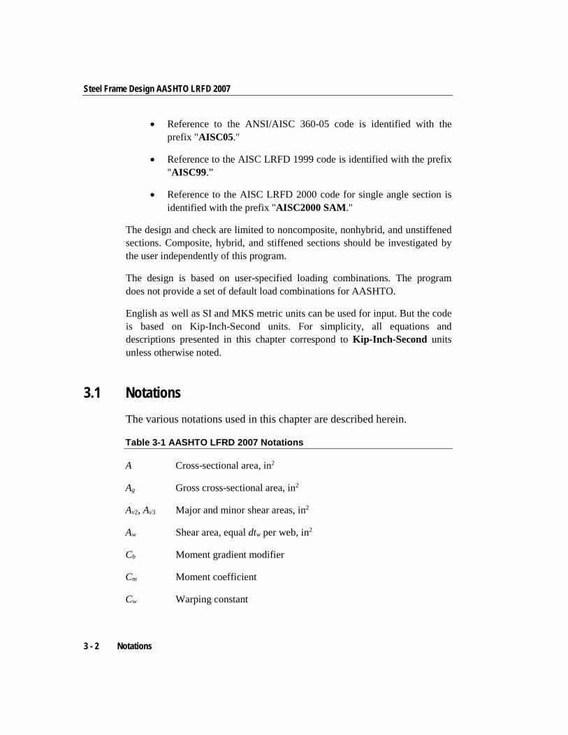
• Reference to the ANSI/AISC 360-05 code is identified with the prefix "AISC05."
• Reference to the AISC LRFD 1999 code is identified with the prefix "AISC99.”
• Reference to the AISC LRFD 2000 code for single angle section is identified with the prefix "AISC2000 SAM."
The design and check are limited to noncomposite, nonhybrid, and unstiffened sections. Composite, hybrid, and stiffened sections should be investigated by the user independently of this program.
The design is based on user-specified loading combinations. The program does not provide a set of default load combinations for AASHTO.
English as well as SI and MKS metric units can be used for input. But the code is based on Kip-Inch-Second units. For simplicity, all equations and descriptions presented in this chapter correspond to Kip-Inch-Second units unless otherwise noted.
3.1 Notations The various notations used in this chapter are described herein.
Table 3-1 AASHTO LFRD 2007 Notations
A Cross-sectional area, in2
Ag Gross cross-sectional area, in2
Av2, Av3 Major and minor shear areas, in2
Aw Shear area, equal dtw per web, in2
Cb Moment gradient modifier
Cm Moment coefficient
Cw Warping constant
3 - 2 Notations
Chapter 3 - Check/Design Using AASHTO LRFD 07
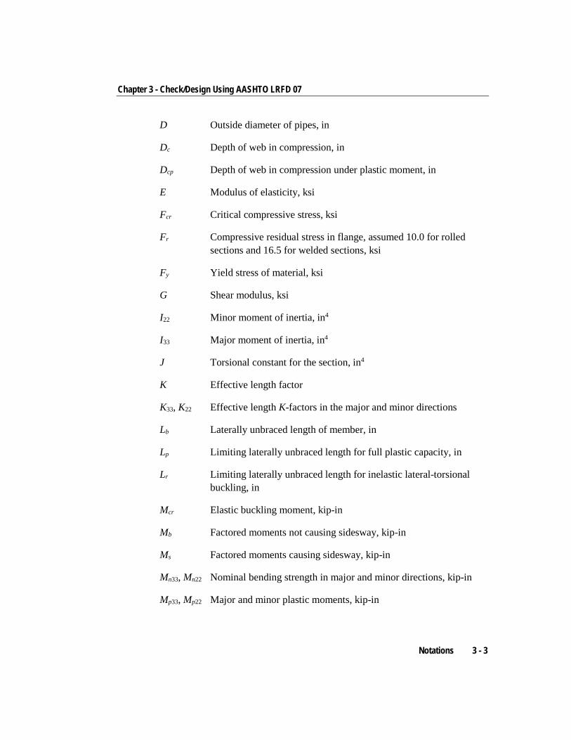
D Outside diameter of pipes, in
Dc Depth of web in compression, in
Dcp Depth of web in compression under plastic moment, in
E Modulus of elasticity, ksi
Fcr Critical compressive stress, ksi
Fr Compressive residual stress in flange, assumed 10.0 for rolled sections and 16.5 for welded sections, ksi
Fy Yield stress of material, ksi
G Shear modulus, ksi
I22 Minor moment of inertia, in4
I33 Major moment of inertia, in4
J Torsional constant for the section, in4
K Effective length factor
K33, K22 Effective length K-factors in the major and minor directions
Lb Laterally unbraced length of member, in
Lp Limiting laterally unbraced length for full plastic capacity, in
Lr Limiting laterally unbraced length for inelastic lateral-torsional buckling, in
Mcr Elastic buckling moment, kip-in
Mb Factored moments not causing sidesway, kip-in
Ms Factored moments causing sidesway, kip-in
Mn33, Mn22 Nominal bending strength in major and minor directions, kip-in
Mp33, Mp22 Major and minor plastic moments, kip-in
Notations 3 - 3
Steel Frame Design AASHTO LRFD 2007
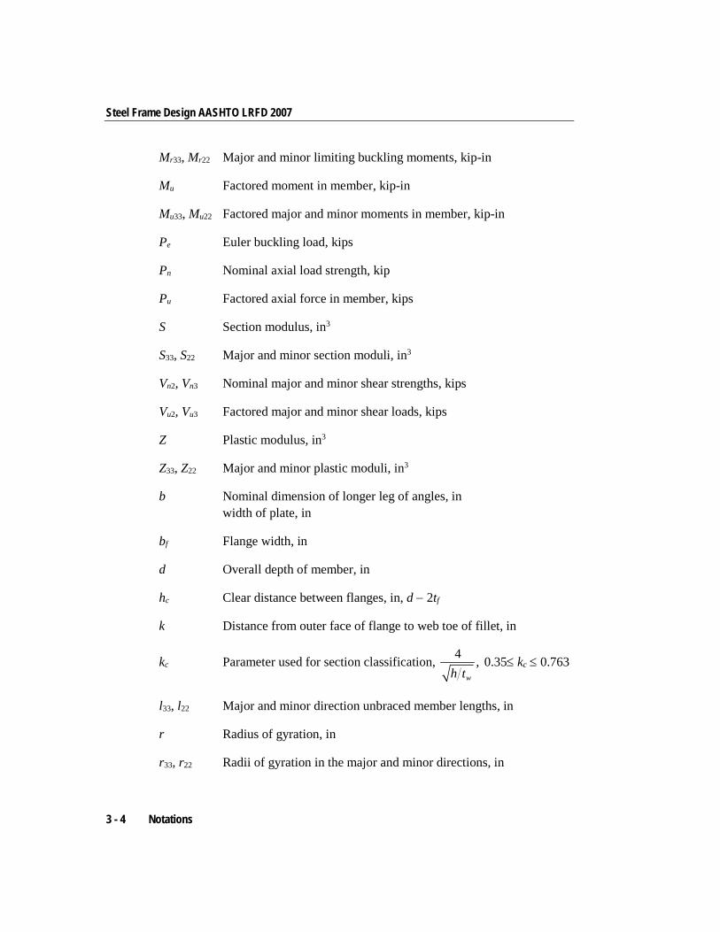
Mr33, Mr22 Major and minor limiting buckling moments, kip-in
Mu Factored moment in member, kip-in
Mu33, Mu22 Factored major and minor moments in member, kip-in
Pe Euler buckling load, kips
Pn Nominal axial load strength, kip
Pu Factored axial force in member, kips
S Section modulus, in3
S33, S22 Major and minor section moduli, in3
Vn2, Vn3 Nominal major and minor shear strengths, kips
Vu2, Vu3 Factored major and minor shear loads, kips
Z Plastic modulus, in3
Z33, Z22 Major and minor plastic moduli, in3
b Nominal dimension of longer leg of angles, in width of plate, in
bf Flange width, in
d Overall depth of member, in
hc Clear distance between flanges, in, d − 2tf
k Distance from outer face of flange to web toe of fillet, in
kc Parameter used for section classification, 4 ,wh t
0.35≤ kc ≤ 0.763
l33, l22 Major and minor direction unbraced member lengths, in
r Radius of gyration, in
r33, r22 Radii of gyration in the major and minor directions, in
3 - 4 Notations
Chapter 3 - Check/Design Using AASHTO LRFD 07
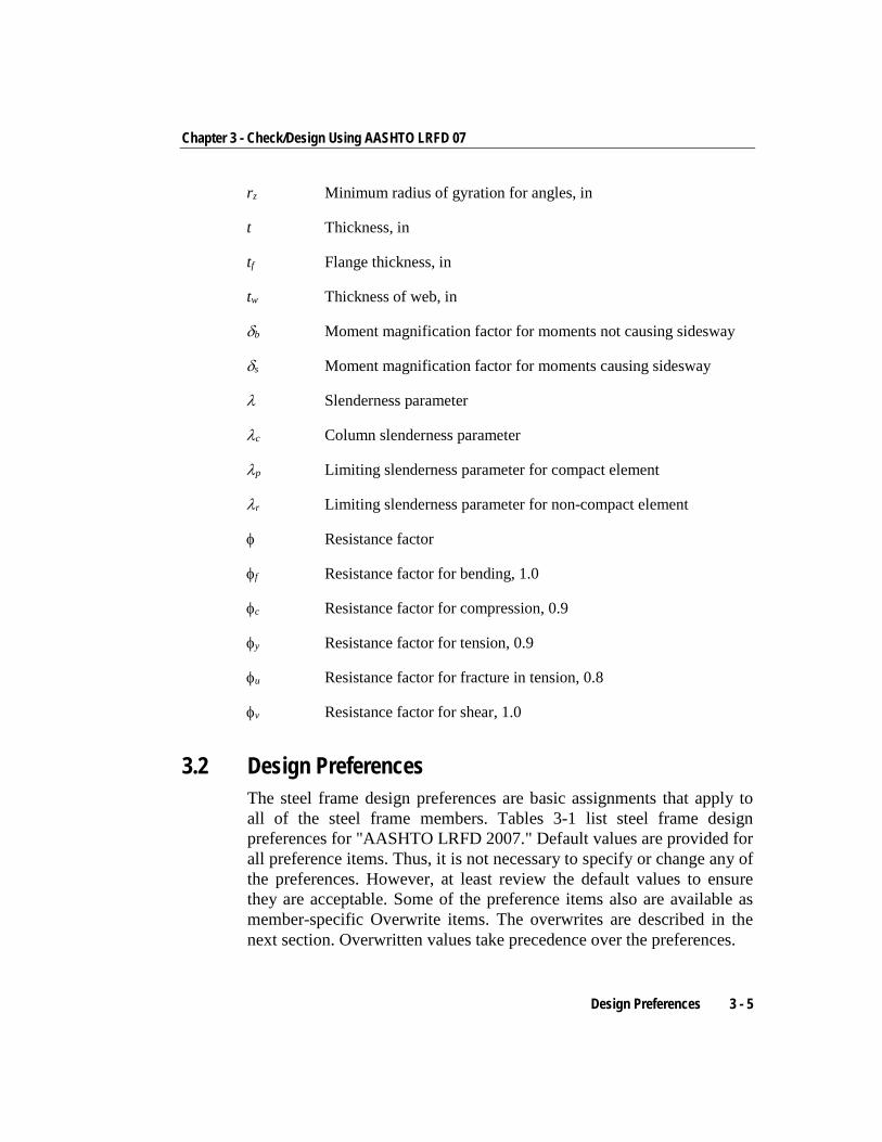
rz Minimum radius of gyration for angles, in
t Thickness, in
tf Flange thickness, in
tw Thickness of web, in
δb Moment magnification factor for moments not causing sidesway
δs Moment magnification factor for moments causing sidesway
λ Slenderness parameter
λc Column slenderness parameter
λp Limiting slenderness parameter for compact element
λr Limiting slenderness parameter for non-compact element
φ Resistance factor
φf Resistance factor for bending, 1.0
φc Resistance factor for compression, 0.9
φy Resistance factor for tension, 0.9
φu Resistance factor for fracture in tension, 0.8
φv Resistance factor for shear, 1.0
3.2 Design Preferences The steel frame design preferences are basic assignments that apply to all of the steel frame members. Tables 3-1 list steel frame design preferences for "AASHTO LRFD 2007." Default values are provided for all preference items. Thus, it is not necessary to specify or change any of the preferences. However, at least review the default values to ensure they are acceptable. Some of the preference items also are available as member-specific Overwrite items. The overwrites are described in the next section. Overwritten values take precedence over the preferences.
Design Preferences 3 - 5
Steel Frame Design AASHTO LRFD 2007
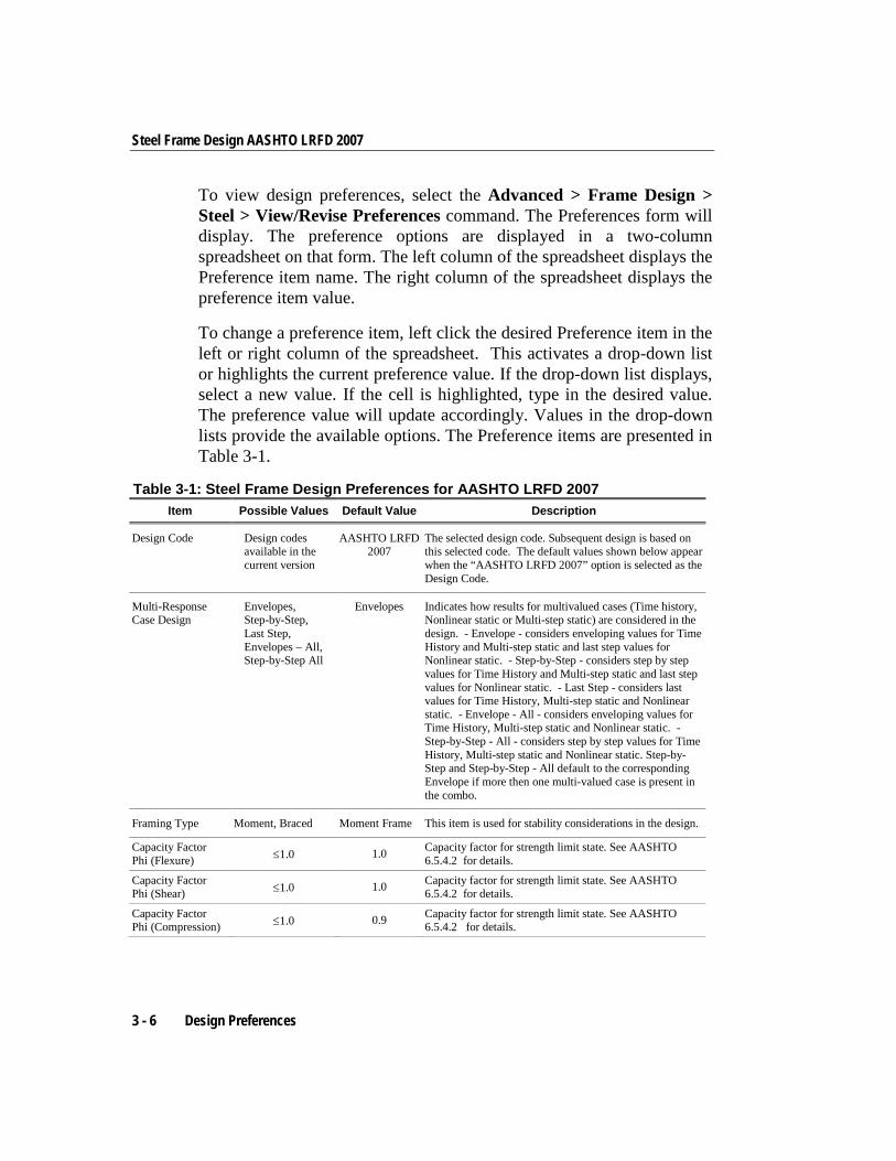
To view design preferences, select the Advanced > Frame Design > Steel > View/Revise Preferences command. The Preferences form will display. The preference options are displayed in a two-column spreadsheet on that form. The left column of the spreadsheet displays the Preference item name. The right column of the spreadsheet displays the preference item value.
To change a preference item, left click the desired Preference item in the left or right column of the spreadsheet. This activates a drop-down list or highlights the current preference value. If the drop-down list displays, select a new value. If the cell is highlighted, type in the desired value. The preference value will update accordingly. Values in the drop-down lists provide the available options. The Preference items are presented in Table 3-1.
Table 3-1: Steel Frame Design Preferences for AASHTO LRFD 2007 Item Possible Values Default Value Description
Design Code Design codes available in the current version
AASHTO LRFD 2007
The selected design code. Subsequent design is based on this selected code. The default values shown below appear when the “AASHTO LRFD 2007” option is selected as the Design Code.
Multi-Response Case Design
Envelopes, Step-by-Step, Last Step, Envelopes – All, Step-by-Step All
Envelopes Indicates how results for multivalued cases (Time history, Nonlinear static or Multi-step static) are considered in the design. - Envelope - considers enveloping values for Time History and Multi-step static and last step values for Nonlinear static. - Step-by-Step - considers step by step values for Time History and Multi-step static and last step values for Nonlinear static. - Last Step - considers last values for Time History, Multi-step static and Nonlinear static. - Envelope - All - considers enveloping values for Time History, Multi-step static and Nonlinear static. - Step-by-Step - All - considers step by step values for Time History, Multi-step static and Nonlinear static. Step-by-Step and Step-by-Step - All default to the corresponding Envelope if more then one multi-valued case is present in the combo.
Framing Type Moment, Braced Moment Frame This item is used for stability considerations in the design.
Capacity Factor Phi (Flexure) ≤1.0 1.0 Capacity factor for strength limit state. See AASHTO
6.5.4.2 for details.
Capacity Factor Phi (Shear) ≤1.0 1.0 Capacity factor for strength limit state. See AASHTO
6.5.4.2 for details.
Capacity Factor Phi (Compression) ≤1.0 0.9 Capacity factor for strength limit state. See AASHTO
6.5.4.2 for details.
3 - 6 Design Preferences
Chapter 3 - Check/Design Using AASHTO LRFD 07
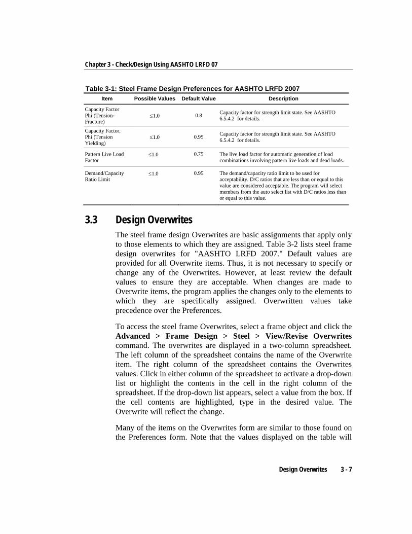
Table 3-1: Steel Frame Design Preferences for AASHTO LRFD 2007 Item Possible Values Default Value Description
Capacity Factor Phi (Tension-Fracture)
≤1.0 0.8 Capacity factor for strength limit state. See AASHTO 6.5.4.2 for details.
Capacity Factor, Phi (Tension Yielding)
≤1.0 0.95 Capacity factor for strength limit state. See AASHTO 6.5.4.2 for details.
Pattern Live Load Factor
≤1.0 0.75 The live load factor for automatic generation of load combinations involving pattern live loads and dead loads.
Demand/Capacity Ratio Limit
≤1.0 0.95 The demand/capacity ratio limit to be used for acceptability. D/C ratios that are less than or equal to this value are considered acceptable. The program will select members from the auto select list with D/C ratios less than or equal to this value.
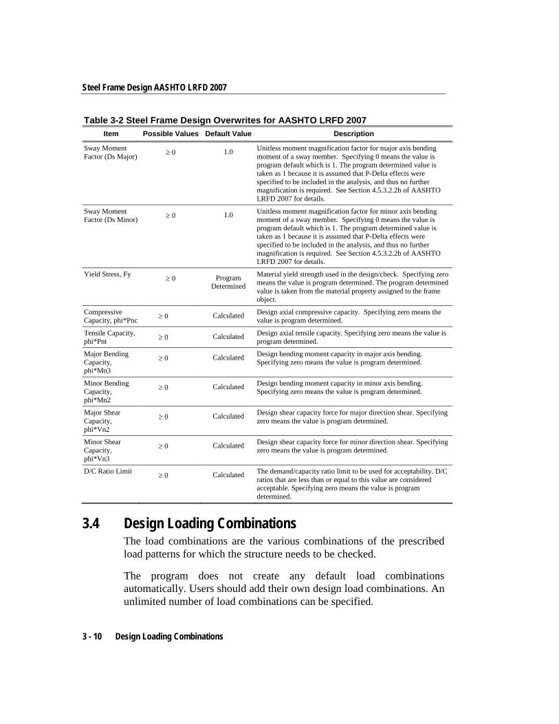
3.3 Design Overwrites The steel frame design Overwrites are basic assignments that apply only to those elements to which they are assigned. Table 3-2 lists steel frame design overwrites for "AASHTO LRFD 2007." Default values are provided for all Overwrite items. Thus, it is not necessary to specify or change any of the Overwrites. However, at least review the default values to ensure they are acceptable. When changes are made to Overwrite items, the program applies the changes only to the elements to which they are specifically assigned. Overwritten values take precedence over the Preferences.
To access the steel frame Overwrites, select a frame object and click the Advanced > Frame Design > Steel > View/Revise Overwrites command. The overwrites are displayed in a two-column spreadsheet. The left column of the spreadsheet contains the name of the Overwrite item. The right column of the spreadsheet contains the Overwrites values. Click in either column of the spreadsheet to activate a drop-down list or highlight the contents in the cell in the right column of the spreadsheet. If the drop-down list appears, select a value from the box. If the cell contents are highlighted, type in the desired value. The Overwrite will reflect the change.
Many of the items on the Overwrites form are similar to those found on the Preferences form. Note that the values displayed on the table will
Design Overwrites 3 - 7
Steel Frame Design AASHTO LRFD 2007
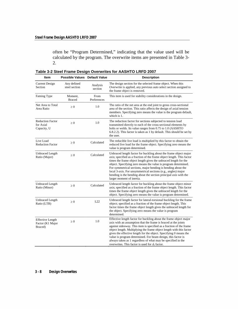
often be “Program Determined,” indicating that the value used will be calculated by the program. The overwrite items are presented in Table 3-2.
Table 3-2 Steel Frame Design Overwrites for AASHTO LRFD 2007 Item Possible Values Default Value Description
Current Design Section
Any defined steel section Analysis
section The design section for the selected frame object. When this Overwrite is applied, any previous auto select section assigned to the frame object is removed.
Faming Type Moment, Braced
From Preferences
This item is used for stability considerations in the design.
Net Area to Total Area Ratio ≥ 0 1.0 The ratio of the net area at the end joint to gross cross-sectional
area of the section. This ratio affects the design of axial tension members. Specifying zero means the value is the program default, which is 1.
Reduction Factor for Axial Capacity, U
≥ 0 1.0 The reduction factor for sections subjected to tension load transmitted directly to each of the cross-sectional elements by bolts or welds. Its value ranges from 0.75 to 1.0 (AASHTO 6.8.2.2). This factor is taken as 1 by default. This should be set by the user.
Live Load Reduction Factor ≥ 0 Calculated The reducible live load is multiplied by this factor to obtain the
reduced live load for the frame object. Specifying zero means the value is program determined.
Unbraced Length Ratio (Major) ≥ 0 Calculated Unbraced length factor for buckling about the frame object major
axis; specified as a fraction of the frame object length. This factor times the frame object length gives the unbraced length for the object. Specifying zero means the value is program determined. For symmetrical sections, major bending is bending about the local 3-axis. For unsymmetrical sections (e.g., angles) major bending is the bending about the section principal axis with the larger moment of inertia.
Unbraced Length Ratio (Minor) ≥ 0 Calculated Unbraced length factor for buckling about the frame object minor
axis; specified as a fraction of the frame object length. This factor times the frame object length gives the unbraced length for the object. Specifying zero means the value is program determined.
Unbraced Length Ratio (LTB) ≥ 0 L22 Unbraced length factor for lateral-torsional buckling for the frame
object; specified as a fraction of the frame object length. This factor times the frame object length gives the unbraced length for the object. Specifying zero means the value is program determined.
Effective Length Factor (K1 Major Braced)
≥ 0 1.0 Effective length factor for buckling about the frame object major axis with an assumption that the frame is braced at the joints against sidesway. This item is specified as a fraction of the frame object length. Multiplying the frame object length with this factor gives the effective length for the object. Specifying 0 means the value is program determined. For beam design, this factor is always taken as 1 regardless of what may be specified in the overwrites. This factor is used for δb factor.
3 - 8 Design Overwrites
Chapter 3 - Check/Design Using AASHTO LRFD 07
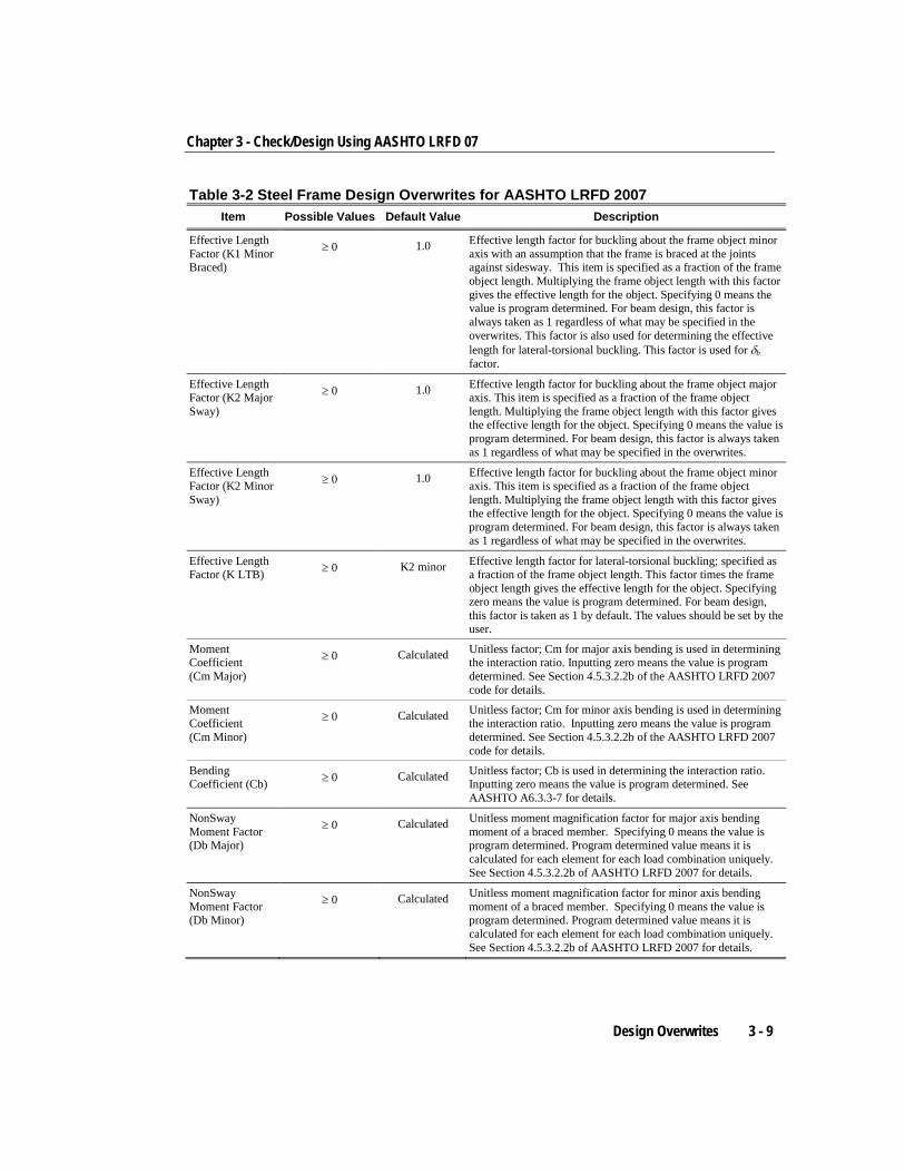
Table 3-2 Steel Frame Design Overwrites for AASHTO LRFD 2007 Item Possible Values Default Value Description
Effective Length Factor (K1 Minor Braced)
≥ 0 1.0 Effective length factor for buckling about the frame object minor axis with an assumption that the frame is braced at the joints against sidesway. This item is specified as a fraction of the frame object length. Multiplying the frame object length with this factor gives the effective length for the object. Specifying 0 means the value is program determined. For beam design, this factor is always taken as 1 regardless of what may be specified in the overwrites. This factor is also used for determining the effective length for lateral-torsional buckling. This factor is used for δb factor.
Effective Length Factor (K2 Major Sway)
≥ 0 1.0 Effective length factor for buckling about the frame object major axis. This item is specified as a fraction of the frame object length. Multiplying the frame object length with this factor gives the effective length for the object. Specifying 0 means the value is program determined. For beam design, this factor is always taken as 1 regardless of what may be specified in the overwrites.
Effective Length Factor (K2 Minor Sway)
≥ 0 1.0 Effective length factor for buckling about the frame object minor axis. This item is specified as a fraction of the frame object length. Multiplying the frame object length with this factor gives the effective length for the object. Specifying 0 means the value is program determined. For beam design, this factor is always taken as 1 regardless of what may be specified in the overwrites.
Effective Length Factor (K LTB) ≥ 0 K2 minor Effective length factor for lateral-torsional buckling; specified as
a fraction of the frame object length. This factor times the frame object length gives the effective length for the object. Specifying zero means the value is program determined. For beam design, this factor is taken as 1 by default. The values should be set by the user.
Moment Coefficient (Cm Major)
≥ 0 Calculated Unitless factor; Cm for major axis bending is used in determining the interaction ratio. Inputting zero means the value is program determined. See Section 4.5.3.2.2b of the AASHTO LRFD 2007 code for details.
Moment Coefficient (Cm Minor)
≥ 0 Calculated Unitless factor; Cm for minor axis bending is used in determining the interaction ratio. Inputting zero means the value is program determined. See Section 4.5.3.2.2b of the AASHTO LRFD 2007 code for details.
Bending Coefficient (Cb) ≥ 0 Calculated Unitless factor; Cb is used in determining the interaction ratio.
Inputting zero means the value is program determined. See AASHTO A6.3.3-7 for details.
NonSway Moment Factor (Db Major)
≥ 0 Calculated Unitless moment magnification factor for major axis bending moment of a braced member. Specifying 0 means the value is program determined. Program determined value means it is calculated for each element for each load combination uniquely. See Section 4.5.3.2.2b of AASHTO LRFD 2007 for details.
NonSway Moment Factor (Db Minor)
≥ 0 Calculated Unitless moment magnification factor for minor axis bending moment of a braced member. Specifying 0 means the value is program determined. Program determined value means it is calculated for each element for each load combination uniquely. See Section 4.5.3.2.2b of AASHTO LRFD 2007 for details.
Design Overwrites 3 - 9
Steel Frame Design AASHTO LRFD 2007
Table 3-2 Steel Frame Design Overwrites for AASHTO LRFD 2007 Item Possible Values Default Value Description
Sway Moment Factor (Ds Major) ≥ 0 1.0 Unitless moment magnification factor for major axis bending
moment of a sway member. Specifying 0 means the value is program default which is 1. The program determined value is taken as 1 because it is assumed that P-Delta effects were specified to be included in the analysis, and thus no further magnification is required. See Section 4.5.3.2.2b of AASHTO LRFD 2007 for details.
Sway Moment Factor (Ds Minor) ≥ 0 1.0 Unitless moment magnification factor for minor axis bending
moment of a sway member. Specifying 0 means the value is program default which is 1. The program determined value is taken as 1 because it is assumed that P-Delta effects were specified to be included in the analysis, and thus no further magnification is required. See Section 4.5.3.2.2b of AASHTO LRFD 2007 for details.
Yield Stress, Fy ≥ 0 Program Determined
Material yield strength used in the design/check. Specifying zero means the value is program determined. The program determined value is taken from the material property assigned to the frame object.
Compressive Capacity, phi*Pnc ≥ 0 Calculated Design axial compressive capacity. Specifying zero means the
value is program determined.
Tensile Capacity, phi*Pnt ≥ 0 Calculated Design axial tensile capacity. Specifying zero means the value is
program determined.
Major Bending Capacity, phi*Mn3
≥ 0 Calculated Design bending moment capacity in major axis bending. Specifying zero means the value is program determined.
Minor Bending Capacity, phi*Mn2
≥ 0 Calculated Design bending moment capacity in minor axis bending. Specifying zero means the value is program determined.
Major Shear Capacity, phi*Vn2
≥ 0 Calculated Design shear capacity force for major direction shear. Specifying zero means the value is program determined.
Minor Shear Capacity, phi*Vn3
≥ 0 Calculated Design shear capacity force for minor direction shear. Specifying zero means the value is program determined.
D/C Ratio Limit ≥ 0 Calculated The demand/capacity ratio limit to be used for acceptability. D/C ratios that are less than or equal to this value are considered acceptable. Specifying zero means the value is program determined.
3.4 Design Loading Combinations The load combinations are the various combinations of the prescribed load patterns for which the structure needs to be checked.
The program does not create any default load combinations automatically. Users should add their own design load combinations. An unlimited number of load combinations can be specified.
3 - 10 Design Loading Combinations
Chapter 3 - Check/Design Using AASHTO LRFD 07
The program checks only the strength limit states. The load combinations should include only Strength and Extreme Event limit states (AASHTO 3.4.1).
There are many types of dead loads, including dead load of structural components and nonstructural attachments (DC), downdrag (DD), dead load of wearing surface and utilities (DW), horizontal earth pressure load (EH), vertical earth pressure load (EV), earth surcharge load (ES). Each type of dead load pattern requires a separate load factor (AASHTO 3.4.1).
There are many types of live loads, including vehicular live load (LL), vehicular dynamic load allowance (IM), vehicular centrifugal force (CE), vehicular braking force (BR), pedestrian live load (PL), and live load surcharge (LS). All these live load pettern require the same factor and do not need to be treated separately (AASHTO 3.4.1).
Live load reduction factors can be applied to the member forces of the live load pattern on an element-by-element basis to reduce the contribution of the live load to the factored loading.
When using the AASHTO code, CSiBridge design assumes that a P-Delta analysis has been performed so that moment magnification factors for moments causing sidesway can be taken as unity. It is recommended that the P- Delta analysis be done at the factored load level (AASHTO C4.5.3.2.1) of 1.25 DL plus 1.75 LL (see White and Hajjar 1991).
3.5 Classification of Sections for Local Buckling The nominal strengths for axial, compression, and flexure are dependent on the classification of the section as Compact, Noncompact, Slender, or Too Slender. Compact sections are capable of developing the full plastic strength before local buckling occurs. Non-compact sections can develop partial yielding in compression, and buckle inelastically before reaching to a fully plastic stress distribution. Slender sections buckle elastically before any of the elements yield under compression.
Classification of Sections for Local Buckling 3 - 11
Steel Frame Design AASHTO LRFD 2007
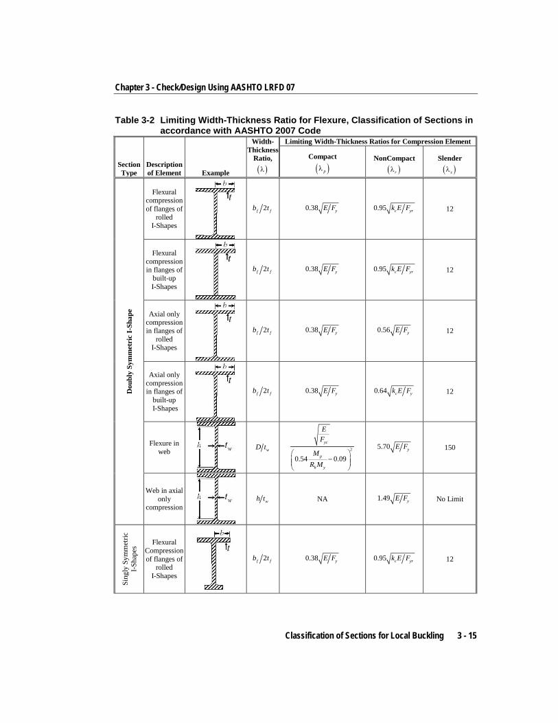
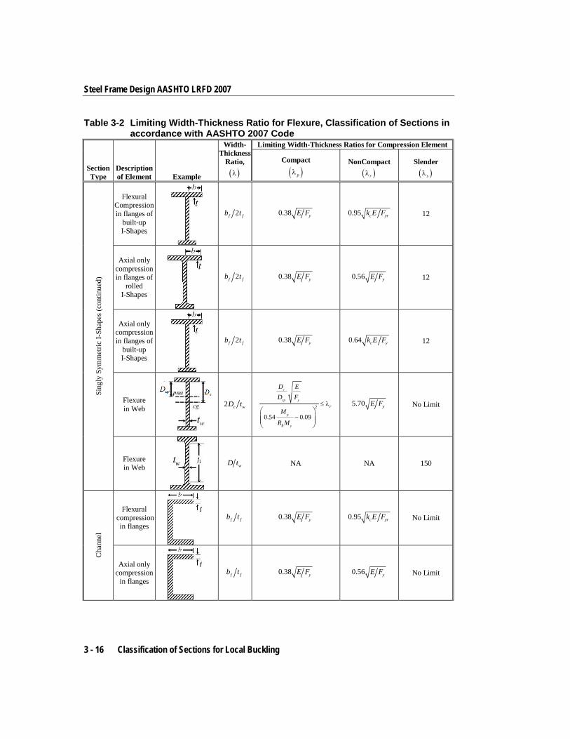
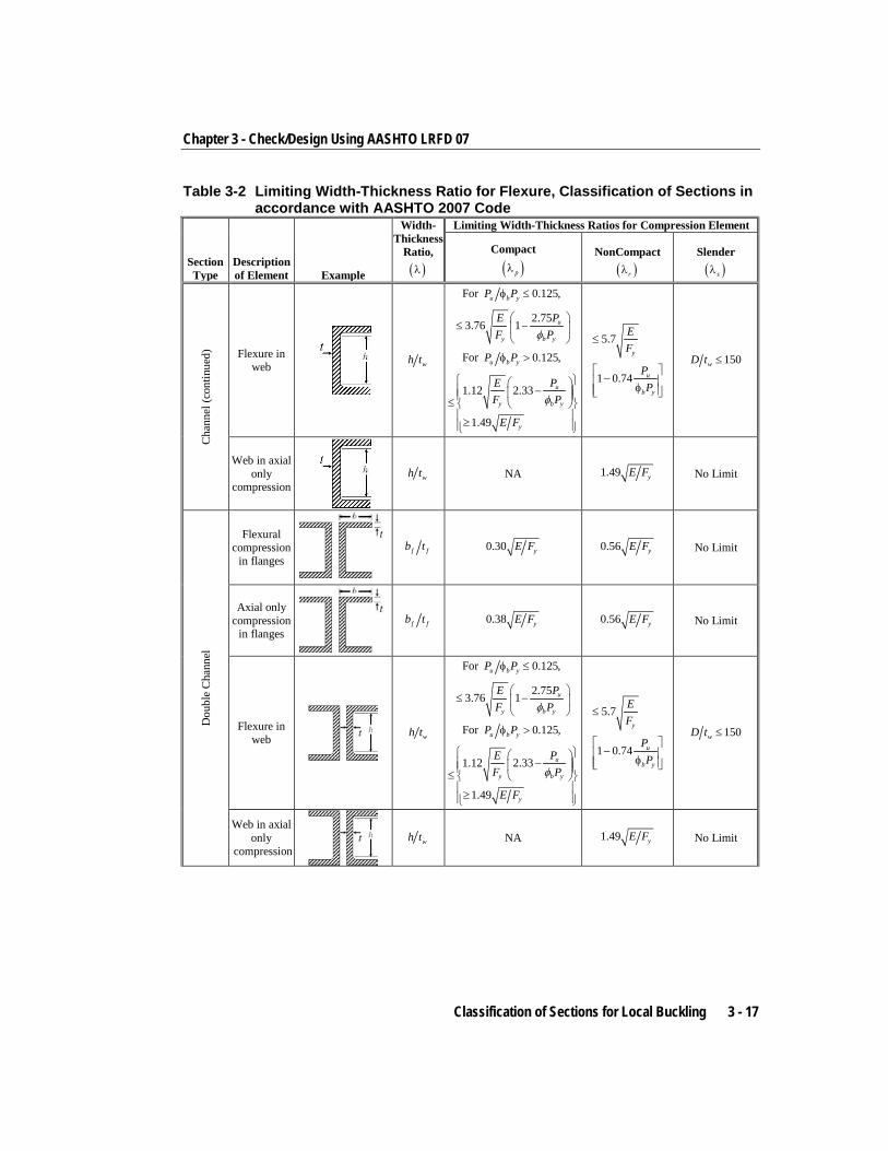
Sections are classified as Compact, Noncompact, or Slender sections in accordance with Section A6.1 and A6.2 (AASHTO 6.10.2.2, 6.10.6.2.3, C6.10.8.1.1, A6.1, A6.2.1) and Section B5.1 of the 1999 AISC code (AASHTO C6.12.2.2.4, AISC99 B5.1, A-G1, Table A-F1.1). For a section to qualify as Compact, its flanges must be continuously connected to the web or webs and the width-thickness ratios of its compression elements must not exceed the limiting width-thickness ratios λp. If the width-thickness ratio of one or more compression elements exceeds λp, but does not exceed λr the section is Noncompact. If the width-thickness ratio of any element exceeds λr but does not exceed λs, the section is Slender. If the width-thickness ratio of any element exceed λs, the section is considered Too Slender. The expressions of λp, λr, and λs, as implemented in the program, are reported in Table 3-1 (AASHTO 6.10.2.2, 6.10.6.2.3, C6.10.8.1.1, A6.1, A6.2.1, AISC99 B5.1, Table B5.1, A-G1, Table A-F1.1, SAM 5.1). The limit demarcating Slender and Too Slender has been identified as λs in this document. The expressions of λs for I-Shape, Double Channel, Channel and T-Shape sections are taken from AASHTO 6.10.2.1 and 6.10.2.2. The expression of λs for Pipe Sections is taken from AASHTO 6.12.2.2.3.
The table uses the variables kc, Fyr, h, hp, hc, Dc, Dcp, bf, tf, tw, b, t, D, d, and so on. The variables b, d, D and t are explained in Figure 3-1. The variables bf, tf, h, hp, hc, Dc, Dcp, and tw are explained in the respective figures inside the table. For Doubly Symmetric I-Shapes, h, hp, and hc are all equal to each other, and Dc is equal to Dcp.
For unstiffened elements supported along only one edge parallel to the direction of compression force, the width shall be taken as follows:
(a) For flanges of I-shaped members and tees, the width b is one-half the full-flange width, bf.
(b) For legs of angles and flanges of channels and zees, the width b is the full nominal dimension.
(c) For plates, the width b is the distance from the free edge to the first row of fasteners or line of welds.
3 - 12 Classification of Sections for Local Buckling
Chapter 3 - Check/Design Using AASHTO LRFD 07
(d) For stems of tees, d is taken as the full nominal depth of the section.
Refer to Table 3-1 for the graphic representation of unstiffened element dimensions.
Classification of Sections for Local Buckling 3 - 13
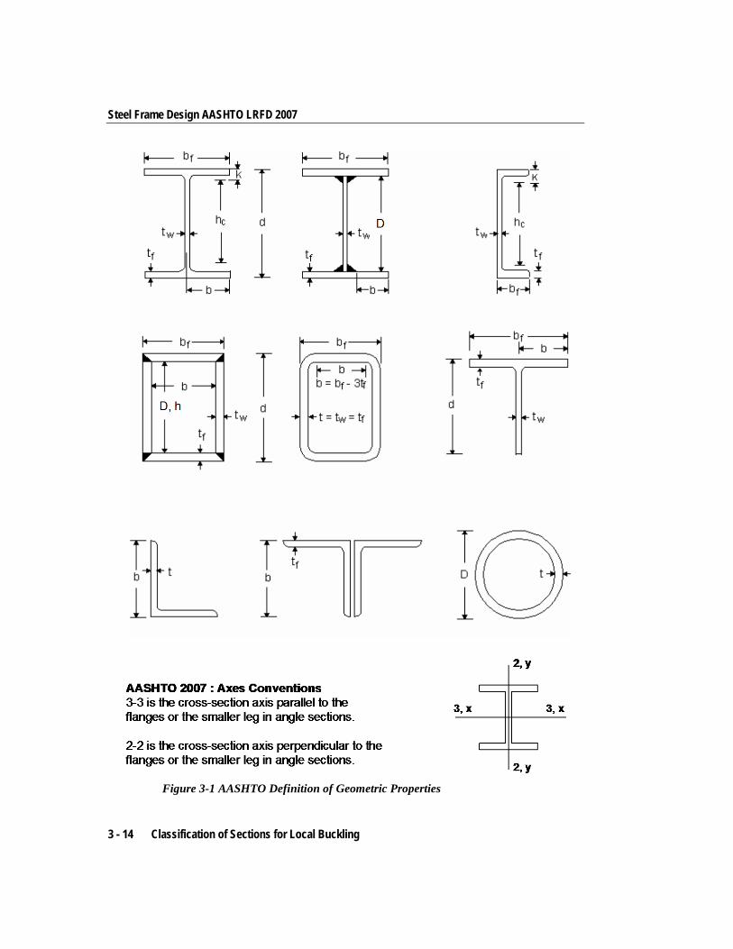
Steel Frame Design AASHTO LRFD 2007
Figure 3-1 AASHTO Definition of Geometric Properties
3 - 14 Classification of Sections for Local Buckling
Chapter 3 - Check/Design Using AASHTO LRFD 07
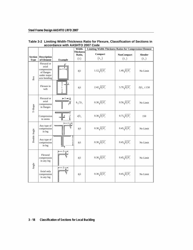
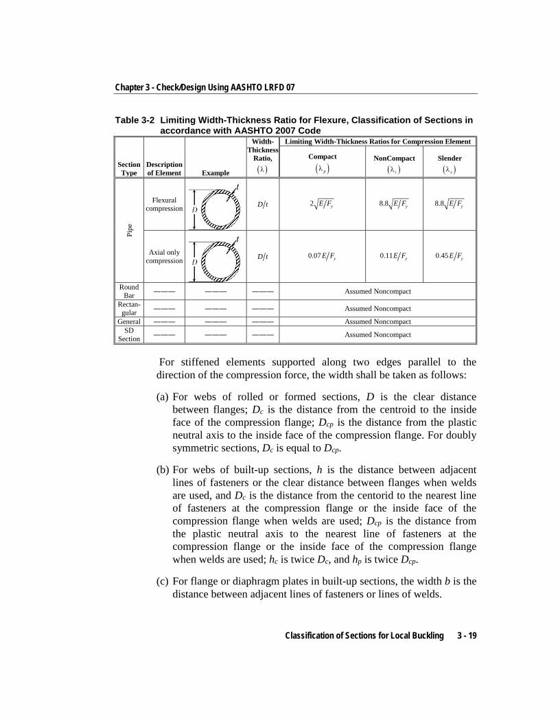
Table 3-2 Limiting Width-Thickness Ratio for Flexure, Classification of Sections in accordance with AASHTO 2007 Code
Section Type
Description of Element Example
Width-Thickness
Ratio, ( )λ
Limiting Width-Thickness Ratios for Compression Element
Compact
( )pλ NonCompact
( )rλ Slender
( )sλ
Dou
bly
Sym
met
ric
I-Sh
ape
Flexural compression of flanges of
rolled I-Shapes
2f fb t 0.38 yE F 0.95 c yrk E F 12
Flexural compression in flanges of
built-up I-Shapes
2f fb t 0.38 yE F 0.95 c yrk E F 12
Axial only compression in flanges of
rolled I-Shapes
2f fb t 0.38 yE F 0.56 yE F 12
Axial only compression in flanges of
built-up I-Shapes
2f fb t 0.38 yE F 0.64 c yk E F 12
Flexure in web
wD t 2
0.54 0.09
yc
p
h y
EF
MR M
−
5.70 yE F 150
Web in axial only
compression
wh t NA 1.49 yE F No Limit
Sing
ly S
ymm
etric
I-S
hape
s Flexural Compression of flanges of
rolled I-Shapes
2f fb t 0.38 yE F 0.95 c yrk E F 12
Classification of Sections for Local Buckling 3 - 15
Steel Frame Design AASHTO LRFD 2007
Table 3-2 Limiting Width-Thickness Ratio for Flexure, Classification of Sections in accordance with AASHTO 2007 Code
Section Type
Description of Element Example
Width-Thickness
Ratio, ( )λ
Limiting Width-Thickness Ratios for Compression Element
Compact
( )pλ NonCompact
( )rλ Slender
( )sλ
Sing
ly S
ymm
etric
I-Sh
apes
(con
tinue
d)
Flexural Compression in flanges of
built-up I-Shapes
2f fb t 0.38 yE F 0.95 c yrk E F 12
Axial only compression in flanges of
rolled I-Shapes
2f fb t 0.38 yE F .0 56 yE F 12
Axial only compression in flanges of
built-up I-Shapes
2f fb t 0.38 yE F 0.64 c yk E F 12
Flexure in Web
2 c wD t 2
0.54 0.09
c
cp y
p
y
r
h
D ED F
M
R M
≤ λ
−
5.70 yE F No Limit
Flexure in Web
wD t NA NA 150
Cha
nnel
Flexural compression
in flanges
f fb t 0.38 yE F 0.95 c yrk E F No Limit
Axial only compression
in flanges
f fb t 0.38 yE F 0.56 yE F No Limit
3 - 16 Classification of Sections for Local Buckling
Chapter 3 - Check/Design Using AASHTO LRFD 07
Table 3-2 Limiting Width-Thickness Ratio for Flexure, Classification of Sections in accordance with AASHTO 2007 Code
Section Type
Description of Element Example
Width-Thickness
Ratio, ( )λ
Limiting Width-Thickness Ratios for Compression Element
Compact
( )pλ NonCompact
( )rλ Slender
( )sλ
Cha
nnel
(con
tinue
d)
Flexure in web
wh t
For 0.125,u b yP Pφ ≤
2.753.76 1 u
y b y
E PF Pφ
≤ −
For 0.125,u b yP Pφ >
1.12 2.33
1.49
u
y b y
y
E PF P
E F
φ
− ≤
≥
5.7
1 0.74
y
u
b y
EF
PP
≤
− φ
150wD t ≤
Web in axial only
compression
wh t NA 1.49 yE F No Limit
Dou
ble
Cha
nnel
Flexural compression
in flanges
f fb t 0.30 yE F 0.56 yE F No Limit
Axial only compression
in flanges
f fb t 0.38 yE F 0.56 yE F No Limit
Flexure in web
wh t
For 0.125,u b yP Pφ ≤
2.753.76 1 u
y b y
E PF Pφ
≤ −
For 0.125,u b yP Pφ >
1.12 2.33
1.49
u
y b y
y
E PF P
E F
φ
− ≤
≥
5.7
1 0.74
y
u
b y
EF
PP
≤
− φ
150wD t ≤
Web in axial only
compression
wh t NA 1.49 yE F No Limit
Classification of Sections for Local Buckling 3 - 17
Steel Frame Design AASHTO LRFD 2007
Table 3-2 Limiting Width-Thickness Ratio for Flexure, Classification of Sections in accordance with AASHTO 2007 Code
Section Type
Description of Element Example
Width-Thickness
Ratio, ( )λ
Limiting Width-Thickness Ratios for Compression Element
Compact
( )pλ NonCompact
( )rλ Slender
( )sλ
Box
Flexural or axial
compression of flanges
under major axis bending
b t 1.12 yE F 1.40 yE F No Limit
Flexure in web
h t 2.42 yE F 5.70 yE F 150wD t ≤
T-Sh
ape
Flexural or axial
compression in flanges
2f fb t 0.30 yE F 0.56 yE F No Limit
Compression
in stems wd t 0.30 yE F 0.75 yE F 150
Dou
ble
Ang
le
Any type of compression
in leg
b t 0.30 yE F 0.45 yE F No Limit
Any type of compression
in leg
b t 0.30 yE F 0.45 yE F No Limit
Ang
le
Flexural compression
in any leg
b t 0.30 yE F 0.45 yE F No Limit
Axial only compression
in any leg
b t 0.30 yE F 0.45 yE F No Limit
3 - 18 Classification of Sections for Local Buckling
Chapter 3 - Check/Design Using AASHTO LRFD 07
Table 3-2 Limiting Width-Thickness Ratio for Flexure, Classification of Sections in accordance with AASHTO 2007 Code
Section Type
Description of Element Example
Width-Thickness
Ratio, ( )λ
Limiting Width-Thickness Ratios for Compression Element
Compact
( )pλ NonCompact
( )rλ Slender
( )sλ
Pipe
Flexural compression
D t 2 yE F 8.8 yE F 8.8 yE F
Axial only compression
D t 0.07 yE F 0.11 yE F 0.45 yE F
Round Bar ――― ――― ――― Assumed Noncompact
Rectan-gular ――― ――― ――― Assumed Noncompact
General ――― ――― ――― Assumed Noncompact SD
Section ――― ――― ――― Assumed Noncompact
For stiffened elements supported along two edges parallel to the direction of the compression force, the width shall be taken as follows:
(a) For webs of rolled or formed sections, D is the clear distance between flanges; Dc is the distance from the centroid to the inside face of the compression flange; Dcp is the distance from the plastic neutral axis to the inside face of the compression flange. For doubly symmetric sections, Dc is equal to Dcp.
(b) For webs of built-up sections, h is the distance between adjacent lines of fasteners or the clear distance between flanges when welds are used, and Dc is the distance from the centorid to the nearest line of fasteners at the compression flange or the inside face of the compression flange when welds are used; Dcp is the distance from the plastic neutral axis to the nearest line of fasteners at the compression flange or the inside face of the compression flange when welds are used; hc is twice Dc, and hp is twice Dcp.
(c) For flange or diaphragm plates in built-up sections, the width b is the distance between adjacent lines of fasteners or lines of welds.
Classification of Sections for Local Buckling 3 - 19
Steel Frame Design AASHTO LRFD 2007
(d) For flanges of rectangular hollow structural sections (HSS), the width b is the clear distance between webs less the inside corner radius on each side. For webs of rectangular HSS, h is the clear distance between the flanges less the inside corner radius on each side, and D is the clear distance between the flanges. If the corner radius is not known, b and h shall be taken as the corresponding outside dimension minus two times the thickness.
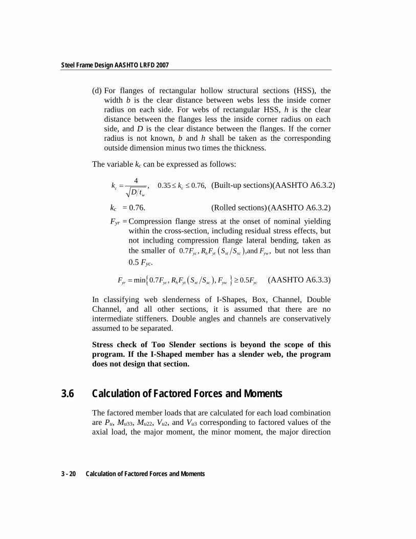
The variable kc can be expressed as follows:
4 ,cw
kD t
= 0.35 0.76,ck≤ ≤ (Built-up sections)(AASHTO A6.3.2)
kc = 0.76. (Rolled sections) (AASHTO A6.3.2)
Fyr = Compression flange stress at the onset of nominal yielding within the cross-section, including residual stress effects, but not including compression flange lateral bending, taken as the smaller of ( )0.7 , ,and ,yc h yt xt xc ywF R F S S F but not less than 0.5 Fyc.
( ){ }min 0.7 , , 0.5yr yc h yt xt xc yw ycF F R F S S F F= ≥ (AASHTO A6.3.3)
In classifying web slenderness of I-Shapes, Box, Channel, Double Channel, and all other sections, it is assumed that there are no intermediate stiffeners. Double angles and channels are conservatively assumed to be separated.
Stress check of Too Slender sections is beyond the scope of this program. If the I-Shaped member has a slender web, the program does not design that section.
3.6 Calculation of Factored Forces and Moments The factored member loads that are calculated for each load combination are Pu, Mu33, Mu22, Vu2, and Vu3 corresponding to factored values of the axial load, the major moment, the minor moment, the major direction
3 - 20 Calculation of Factored Forces and Moments
Chapter 3 - Check/Design Using AASHTO LRFD 07
shear force, and the minor direction shear force, respectively. These factored loads are calculated at each of the previously defined stations.
For loading combinations that cause compression in the member, the factored moment Mu (Mu33 and Mu22 in the corresponding directions) is magnified to consider second order effects. The magnified moment in a particular direction is given by:
Mu = δb Mb + δs Ms, where (AASHTO 4.5.3.2.2b)
δb = Moment magnification factor for moments in braced mode, δs = Moment magnification factor for moments in sidesway
mode, Mb = Factored moments not causing sidesway, and Ms = Factored moments causing sidesway.
The moment magnification factors are associated with corresponding directions. The moment magnification factor for moments not causing sidesway is given by
1.0,1
mb
u
k e
CPP
δ
φ
= ≥−
where (AASHTO 4.5.3.2.2b)
Pe is the Euler buckling load,
( )
2
21
,eu
EIPK lπ
= (AASHTO 4.5.3.2.2b)
1.0kφ = (AASHTO 4.5.3.2.2b)
0.6 0.4 ,am
b
MCM
= + where (AASHTO 4.5.3.2.2b)
a bM M is the ratio of the smaller to the larger nonsway moments at the ends of the member, a bM M being positive for single curvature bending and negative for double curvature bending. For compression members with transverse load on the member, Cm is assumed as 1.0. When Mb is zero, Cm is taken as 1.0. The program defaults Cm to 1.0
Calculation of Factored Forces and Moments 3 - 21
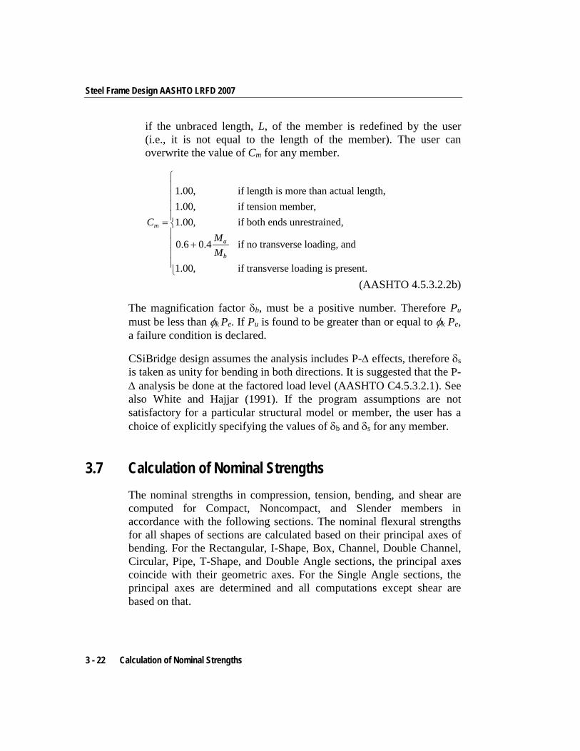
Steel Frame Design AASHTO LRFD 2007
if the unbraced length, L, of the member is redefined by the user (i.e., it is not equal to the length of the member). The user can overwrite the value of Cm for any member.
1.00, if length is more than actual length,1.00, if tension member,1.00, if both ends unrestrained,
0.6 0.4 if no transverse loading, and
1.00, if transverse loading is present.
m
a
b
CMM
= +
(AASHTO 4.5.3.2.2b)
The magnification factor δb, must be a positive number. Therefore Pu must be less than φk Pe. If Pu is found to be greater than or equal to φk Pe, a failure condition is declared.
CSiBridge design assumes the analysis includes P-∆ effects, therefore δs is taken as unity for bending in both directions. It is suggested that the P-∆ analysis be done at the factored load level (AASHTO C4.5.3.2.1). See also White and Hajjar (1991). If the program assumptions are not satisfactory for a particular structural model or member, the user has a choice of explicitly specifying the values of δb and δs for any member.
3.7 Calculation of Nominal Strengths The nominal strengths in compression, tension, bending, and shear are computed for Compact, Noncompact, and Slender members in accordance with the following sections. The nominal flexural strengths for all shapes of sections are calculated based on their principal axes of bending. For the Rectangular, I-Shape, Box, Channel, Double Channel, Circular, Pipe, T-Shape, and Double Angle sections, the principal axes coincide with their geometric axes. For the Single Angle sections, the principal axes are determined and all computations except shear are based on that.
3 - 22 Calculation of Nominal Strengths
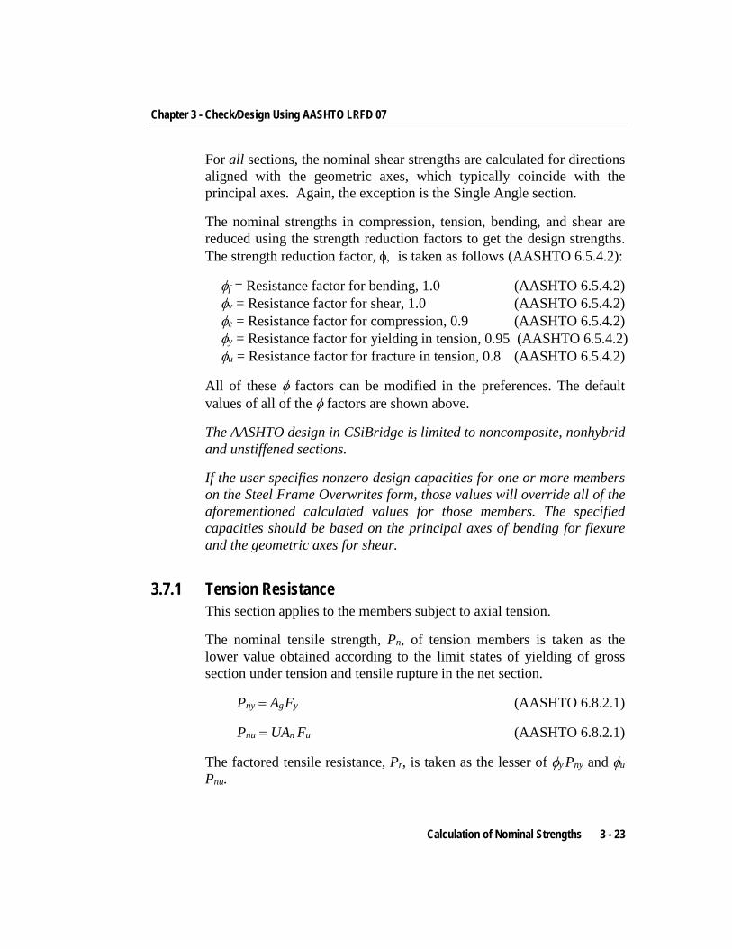
Chapter 3 - Check/Design Using AASHTO LRFD 07
For all sections, the nominal shear strengths are calculated for directions aligned with the geometric axes, which typically coincide with the principal axes. Again, the exception is the Single Angle section.
The nominal strengths in compression, tension, bending, and shear are reduced using the strength reduction factors to get the design strengths. The strength reduction factor, φ, is taken as follows (AASHTO 6.5.4.2):
φf = Resistance factor for bending, 1.0 (AASHTO 6.5.4.2) φv = Resistance factor for shear, 1.0 (AASHTO 6.5.4.2) φc = Resistance factor for compression, 0.9 (AASHTO 6.5.4.2) φy = Resistance factor for yielding in tension, 0.95 (AASHTO 6.5.4.2) φu = Resistance factor for fracture in tension, 0.8 (AASHTO 6.5.4.2)
All of these φ factors can be modified in the preferences. The default values of all of the φ factors are shown above.
The AASHTO design in CSiBridge is limited to noncomposite, nonhybrid and unstiffened sections.
If the user specifies nonzero design capacities for one or more members on the Steel Frame Overwrites form, those values will override all of the aforementioned calculated values for those members. The specified capacities should be based on the principal axes of bending for flexure and the geometric axes for shear.
3.7.1 Tension Resistance This section applies to the members subject to axial tension.
The nominal tensile strength, Pn, of tension members is taken as the lower value obtained according to the limit states of yielding of gross section under tension and tensile rupture in the net section.
Pny = Ag Fy (AASHTO 6.8.2.1)
Pnu = UAn Fu (AASHTO 6.8.2.1)
The factored tensile resistance, Pr, is taken as the lesser of φy Pny and φu
Pnu.
Calculation of Nominal Strengths 3 - 23
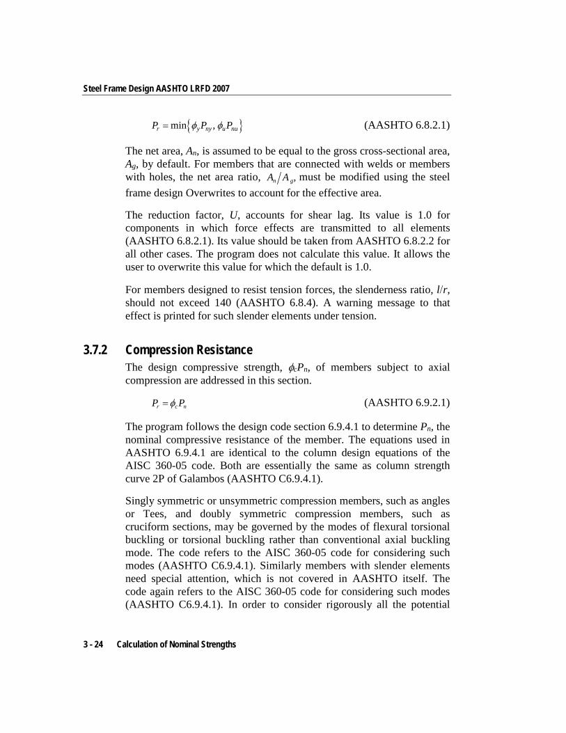
Steel Frame Design AASHTO LRFD 2007
{ }min ,r y ny u nuP P Pφ φ= (AASHTO 6.8.2.1)
The net area, An, is assumed to be equal to the gross cross-sectional area, Ag, by default. For members that are connected with welds or members with holes, the net area ratio, ,n gA A must be modified using the steel frame design Overwrites to account for the effective area.
The reduction factor, U, accounts for shear lag. Its value is 1.0 for components in which force effects are transmitted to all elements (AASHTO 6.8.2.1). Its value should be taken from AASHTO 6.8.2.2 for all other cases. The program does not calculate this value. It allows the user to overwrite this value for which the default is 1.0.
For members designed to resist tension forces, the slenderness ratio, l/r, should not exceed 140 (AASHTO 6.8.4). A warning message to that effect is printed for such slender elements under tension.
3.7.2 Compression Resistance The design compressive strength, φcPn, of members subject to axial compression are addressed in this section.
r c nP Pφ= (AASHTO 6.9.2.1)
The program follows the design code section 6.9.4.1 to determine Pn , the nominal compressive resistance of the member. The equations used in AASHTO 6.9.4.1 are identical to the column design equations of the AISC 360-05 code. Both are essentially the same as column strength curve 2P of Galambos (AASHTO C6.9.4.1).
Singly symmetric or unsymmetric compression members, such as angles or Tees, and doubly symmetric compression members, such as cruciform sections, may be governed by the modes of flexural torsional buckling or torsional buckling rather than conventional axial buckling mode. The code refers to the AISC 360-05 code for considering such modes (AASHTO C6.9.4.1). Similarly members with slender elements need special attention, which is not covered in AASHTO itself. The code again refers to the AISC 360-05 code for considering such modes (AASHTO C6.9.4.1). In order to consider rigorously all the potential
3 - 24 Calculation of Nominal Strengths
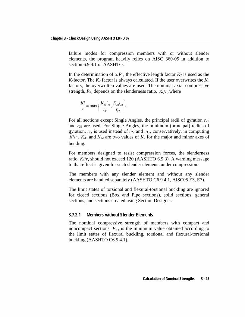
Chapter 3 - Check/Design Using AASHTO LRFD 07
failure modes for compression members with or without slender elements, the program heavily relies on AISC 360-05 in addition to section 6.9.4.1 of AASHTO.
In the determination of φcPn, the effective length factor K2 is used as the K-factor. The K2 factor is always calculated. If the user overwrites the K2 factors, the overwritten values are used. The nominal axial compressive strength, Pn , depends on the slenderness ratio, ,Kl r where
33 33 22 22
33 22
max , .K l K lKlr r r
=
For all sections except Single Angles, the principal radii of gyration r22 and r33 are used. For Single Angles, the minimum (principal) radius of gyration, rz , is used instead of r22 and r33 , conservatively, in computing
.Kl r K33 and K22 are two values of K2 for the major and minor axes of bending.
For members designed to resist compression forces, the slenderness ratio, Kl/r, should not exceed 120 (AASHTO 6.9.3). A warning message to that effect is given for such slender elements under compression.
The members with any slender element and without any slender elements are handled separately (AASHTO C6.9.4.1, AISC05 E3, E7).
The limit states of torsional and flexural-torsional buckling are ignored for closed sections (Box and Pipe sections), solid sections, general sections, and sections created using Section Designer.
3.7.2.1 Members without Slender Elements The nominal compressive strength of members with compact and noncompact sections, Pn , is the minimum value obtained according to the limit states of flexural buckling, torsional and flexural-torsional buckling (AASHTO C6.9.4.1).
Calculation of Nominal Strengths 3 - 25
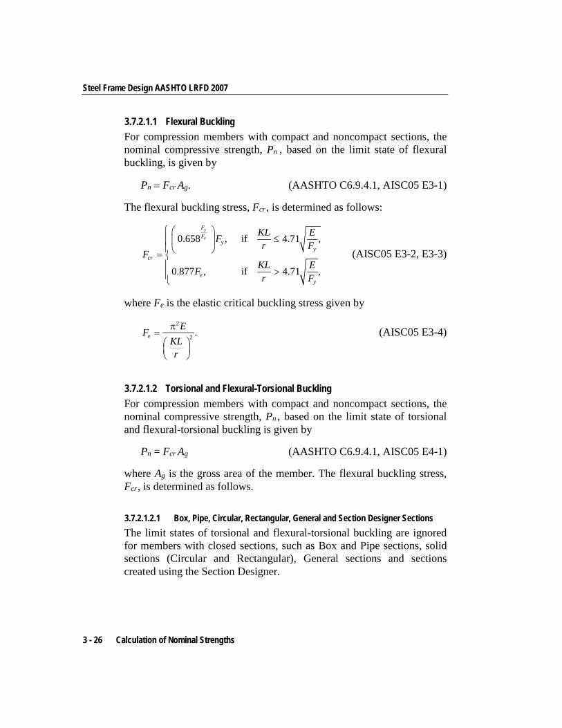
Steel Frame Design AASHTO LRFD 2007
3.7.2.1.1 Flexural Buckling For compression members with compact and noncompact sections, the nominal compressive strength, Pn , based on the limit state of flexural buckling, is given by
Pn = Fcr Ag. (AASHTO C6.9.4.1, AISC05 E3-1)
The flexural buckling stress, Fcr , is determined as follows:
0.658 , if 4.71 ,
0.877 , if 4.71 ,
y
e
FF
yy
cr
ey
KL EFr F
FKL EFr F
≤
= >
(AISC05 E3-2, E3-3)
where Fe is the elastic critical buckling stress given by
2
2 .eEF
KLr
π=
(AISC05 E3-4)
3.7.2.1.2 Torsional and Flexural-Torsional Buckling For compression members with compact and noncompact sections, the nominal compressive strength, Pn , based on the limit state of torsional and flexural-torsional buckling is given by
Pn = Fcr Ag (AASHTO C6.9.4.1, AISC05 E4-1)
where Ag is the gross area of the member. The flexural buckling stress, Fcr , is determined as follows.
3.7.2.1.2.1 Box, Pipe, Circular, Rectangular, General and Section Designer Sections The limit states of torsional and flexural-torsional buckling are ignored for members with closed sections, such as Box and Pipe sections, solid sections (Circular and Rectangular), General sections and sections created using the Section Designer.
3 - 26 Calculation of Nominal Strengths
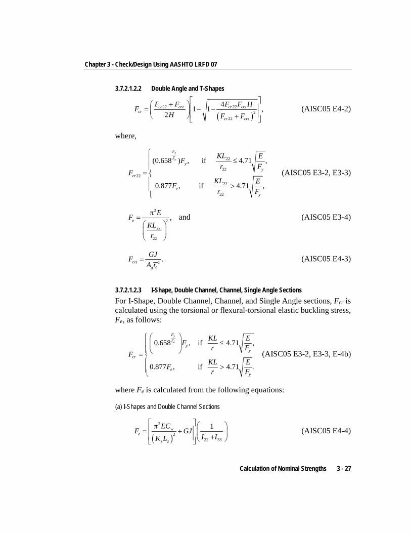
Chapter 3 - Check/Design Using AASHTO LRFD 07
3.7.2.1.2.2 Double Angle and T-Shapes
( )
22 222
22
41 1 ,2
cr crz cr crzcr
cr crz
F F F F HFH F F
+ = − − + (AISC05 E4-2)
where,
22
2222
22
22
(0.658 ) , if 4.71 ,
0.877 , if 4.71 ,
y
e
FF
yy
cr
ey
KL EFr F
FKL EFr F
≤
=
>
(AISC05 E3-2, E3-3)
2
2
22
22
,eEF
KLr
π=
and (AISC05 E3-4)
20
.crzg
GJFA r
= (AISC05 E4-3)
3.7.2.1.2.3 I-Shape, Double Channel, Channel, Single Angle Sections For I-Shape, Double Channel, Channel, and Single Angle sections, Fcr is calculated using the torsional or flexural-torsional elastic buckling stress, Fe , as follows:
0.658 , if 4.71 ,
0.877 , if 4.71 .
y
e
FF
yy
cr
ey
KL EFr F
FKL EFr F
≤
= >
(AISC05 E3-2, E3-3, E-4b)
where Fe is calculated from the following equations:
(a) I-Shapes and Double Channel Sections
( )
2
222 33
1we
z z
ECF GJI IK L
π = + + (AISC05 E4-4)
Calculation of Nominal Strengths 3 - 27
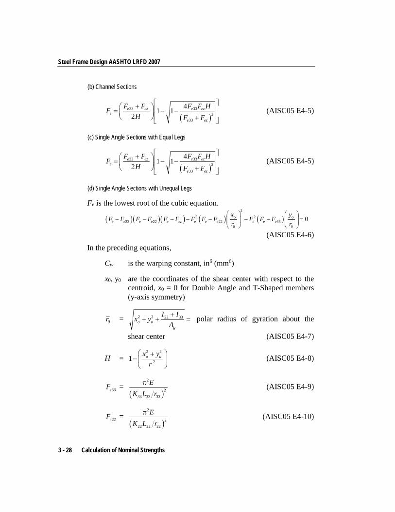
Steel Frame Design AASHTO LRFD 2007
(b) Channel Sections
( )
33 332
33
41 12
e ez e eze
e ez
F F F F HFH F F
+ = − − + (AISC05 E4-5)
(c) Single Angle Sections with Equal Legs
( )
33 332
33
41 1
2e ez e ez
e
e ez
F F F F HF
H F F
+ = − − + (AISC05 E4-5)
(d) Single Angle Sections with Unequal Legs
Fe is the lowest root of the cubic equation.
( )( )( ) ( ) ( )2
2 233 22 22 33
0 0
0o oe e e e e ez e e e e e e
x yF F F F F F F F F F F F
r r
− − − − − − − =
(AISC05 E4-6)
In the preceding equations,
Cw is the warping constant, in6 (mm6)
x0, y0 are the coordinates of the shear center with respect to the centroid, x0 = 0 for Double Angle and T-Shaped members (y-axis symmetry)
0r = 2 2 22 33o o
g
I Ix yA+
+ + = polar radius of gyration about the
shear center (AISC05 E4-7)
H = 2 2
21 o ox yr
+−
(AISC05 E4-8)
33eF = ( )
2
233 33 33
EK L r
π (AISC05 E4-9)
22eF = ( )
2
222 22 22
EK L r
π (AISC05 E4-10)
3 - 28 Calculation of Nominal Strengths
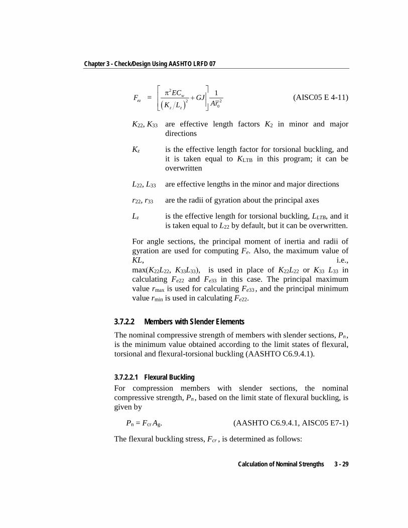
Chapter 3 - Check/Design Using AASHTO LRFD 07
ezF = ( )
2
2 20
1w
z z
EC GJArK L
π +
(AISC05 E 4-11)
K22, K33 are effective length factors K2 in minor and major directions
Kz is the effective length factor for torsional buckling, and it is taken equal to KLTB in this program; it can be overwritten
L22, L33 are effective lengths in the minor and major directions
r22, r33 are the radii of gyration about the principal axes
Lz is the effective length for torsional buckling, LLTB, and it is taken equal to L22 by default, but it can be overwritten.
For angle sections, the principal moment of inertia and radii of gyration are used for computing Fe. Also, the maximum value of KL, i.e., max(K22L22, K33L33), is used in place of K22L22 or K33 L33 in calculating Fe22 and Fe33 in this case. The principal maximum value rmax is used for calculating Fe33 , and the principal minimum value rmin is used in calculating Fe22.
3.7.2.2 Members with Slender Elements The nominal compressive strength of members with slender sections, Pn , is the minimum value obtained according to the limit states of flexural, torsional and flexural-torsional buckling (AASHTO C6.9.4.1).
3.7.2.2.1 Flexural Buckling For compression members with slender sections, the nominal compressive strength, Pn , based on the limit state of flexural buckling, is given by
Pn = Fcr Ag. (AASHTO C6.9.4.1, AISC05 E7-1)
The flexural buckling stress, Fcr , is determined as follows:
Calculation of Nominal Strengths 3 - 29
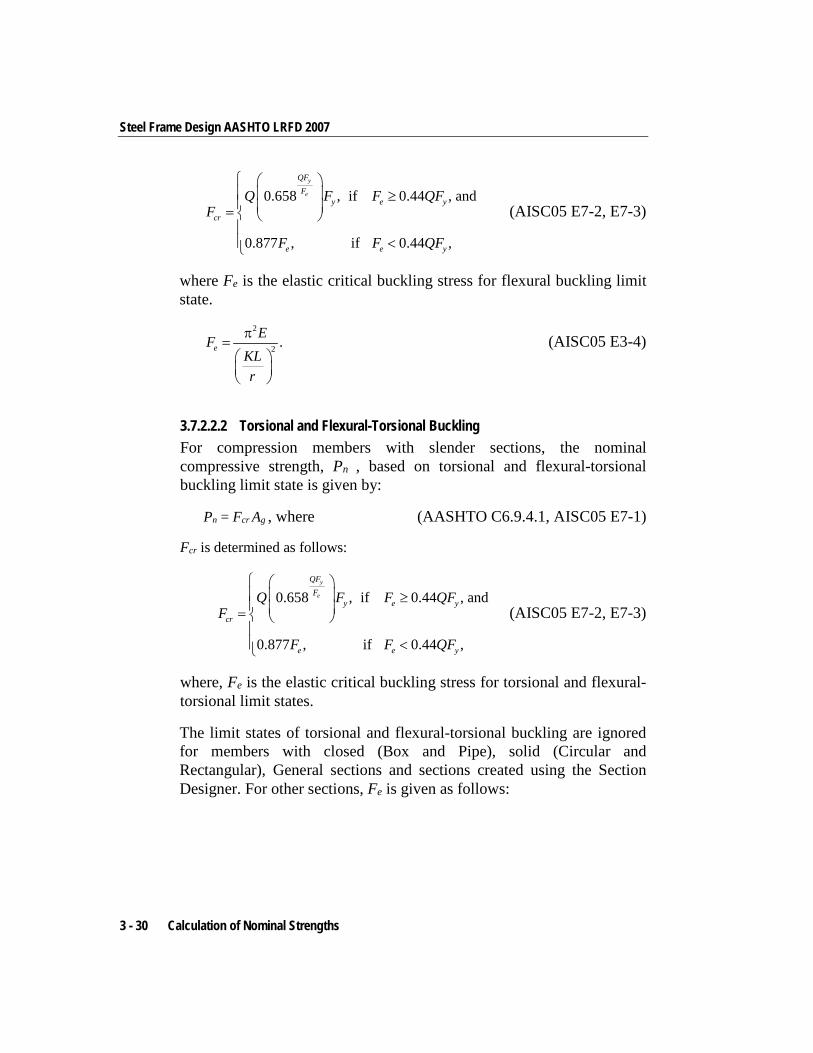
Steel Frame Design AASHTO LRFD 2007
0.658 , if 0.44 , and
0.877 , if 0.44 ,
y
e
QFF
y e y
cr
e e y
Q F F QFF
F F QF
≥ = <
(AISC05 E7-2, E7-3)
where Fe is the elastic critical buckling stress for flexural buckling limit state.
2
2 .eEF
KLr
π=
(AISC05 E3-4)
3.7.2.2.2 Torsional and Flexural-Torsional Buckling For compression members with slender sections, the nominal compressive strength, Pn , based on torsional and flexural-torsional buckling limit state is given by:
Pn = Fcr Ag , where (AASHTO C6.9.4.1, AISC05 E7-1)
Fcr is determined as follows:
0.658 , if 0.44 , and
0.877 , if 0.44 ,
y
e
QFF
y e y
cr
e e y
Q F F QFF
F F QF
≥ = <
(AISC05 E7-2, E7-3)
where, Fe is the elastic critical buckling stress for torsional and flexural-torsional limit states.
The limit states of torsional and flexural-torsional buckling are ignored for members with closed (Box and Pipe), solid (Circular and Rectangular), General sections and sections created using the Section Designer. For other sections, Fe is given as follows:
3 - 30 Calculation of Nominal Strengths
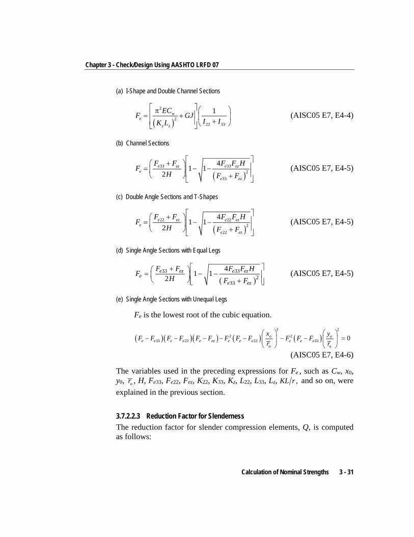
Chapter 3 - Check/Design Using AASHTO LRFD 07
(a) I-Shape and Double Channel Sections
( )
2
222 33
1we
z z
ECF GJI IK L
π = + + (AISC05 E7, E4-4)
(b) Channel Sections
( )
33 332
33
41 1
2e ez e ez
e
e ez
F F F F HF
H F F
+ = − − + (AISC05 E7, E4-5)
(c) Double Angle Sections and T-Shapes
( )
22 222
22
41 1
2e ez e ez
e
e ez
F F F F HF
H F F
+ = − − + (AISC05 E7, E4-5)
(d) Single Angle Sections with Equal Legs
( )
33 332
33
41 12
e ez e eze
e ez
F F F F HFH F F
+ = − − +
(AISC05 E7, E4-5)
(e) Single Angle Sections with Unequal Legs
Fe is the lowest root of the cubic equation.
( )( )( ) ( ) ( )2 2
2 233 22 22 33 0o o
e e e e e ez e e e e e eo o
x yF F F F F F F F F F F F
r r
− − − − − − − =
(AISC05 E7, E4-6)
The variables used in the preceding expressions for Fe , such as Cw, x0, y0, or , H, Fe33, Fe22, Fez, K22, K33, Kz, L22, L33, Lz, ,KL r and so on, were explained in the previous section.
3.7.2.2.3 Reduction Factor for Slenderness The reduction factor for slender compression elements, Q, is computed as follows:
Calculation of Nominal Strengths 3 - 31
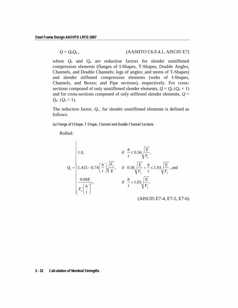
Steel Frame Design AASHTO LRFD 2007
Q = QsQa , (AASHTO C6.9.4.1, AISC05 E7)
where Qs and Qa are reduction factors for slender unstiffened compression elements (flanges of I-Shapes, T-Shapes, Double Angles, Channels, and Double Channels; legs of angles; and stems of T-Shapes) and slender stiffened compression elements (webs of I-Shapes, Channels, and Boxes; and Pipe sections), respectively. For cross-sections composed of only unstiffened slender elements, Q = Qs (Qa = 1) and for cross-sections composed of only stiffened slender elements, Q = Qa (Qs = 1).
The reduction factor, Qs , for slender unstiffened elements is defined as follows:
(a) Flange of I-Shape, T-Shape, Channel and Double Channel Sections
Rolled:
2
1.0, if 0.56 ,
1.415 0.74 , if 0.56 1.03 , and
0.69 , if 1.03 .
y
ys
y y
yy
b Et F
Fb E b EQt E F t F
E b Et FbF
t
≤ = − < ≤
>
(AISC05 E7-4, E7-5, E7-6)
3 - 32 Calculation of Nominal Strengths
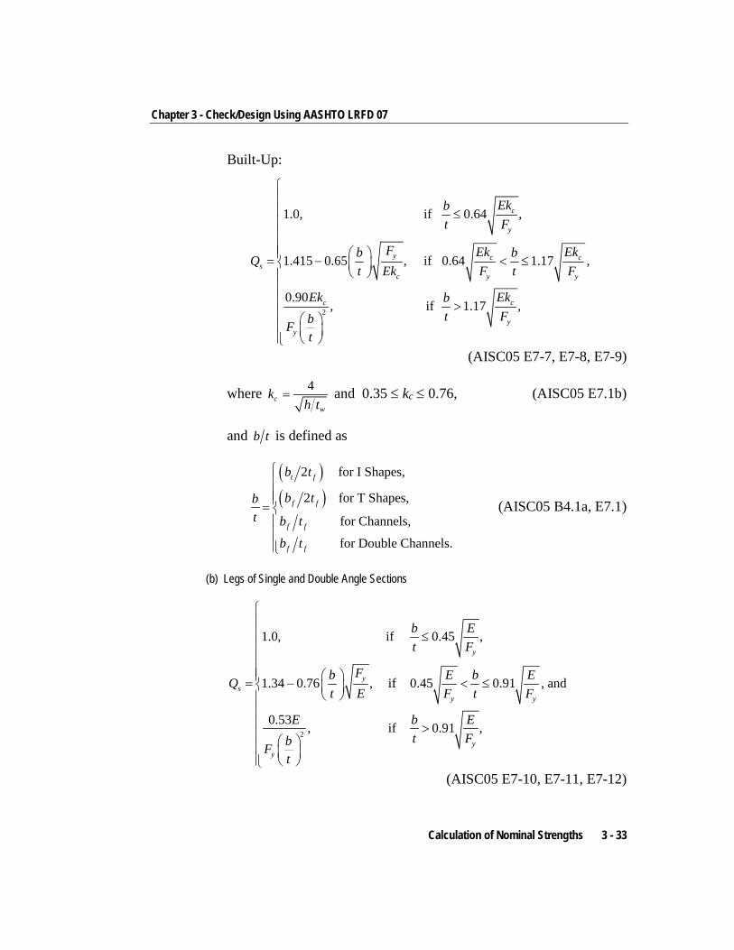
Chapter 3 - Check/Design Using AASHTO LRFD 07
Built-Up:
2
1.0, if 0.64 ,
1.415 0.65 , if 0.64 1.17 ,
0.90 , if 1.17 ,
c
y
y c cs
c y y
c c
yy
Ekbt F
F Ek Ekb bQt Ek F t F
Ek Ekbt FbF
t
≤ = − < ≤
>
(AISC05 E7-7, E7-8, E7-9)
where 4c
w
kh t
= and 0.35 ≤ kc ≤ 0.76, (AISC05 E7.1b)
and b t is defined as
( )( )
2 for I Shapes,
2 for T Shapes,
for Channels,
for Double Channels.
t f
f f
f f
f f
b t
b tbt b t
b t
=
(AISC05 B4.1a, E7.1)
(b) Legs of Single and Double Angle Sections
2
1.0, if 0.45 ,
1.34 0.76 , if 0.45 0.91 , and
0.53 , if 0.91 ,
y
ys
y y
yy
b Et F
Fb E b EQt E F t F
E b Et FbF
t
≤ = − < ≤
>
(AISC05 E7-10, E7-11, E7-12)
Calculation of Nominal Strengths 3 - 33
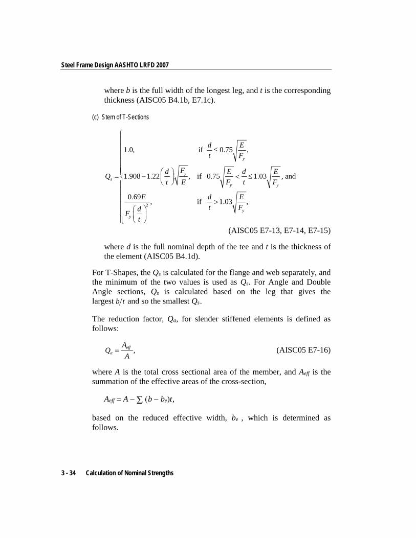
Steel Frame Design AASHTO LRFD 2007
where b is the full width of the longest leg, and t is the corresponding thickness (AISC05 B4.1b, E7.1c).
(c) Stem of T-Sections
2
1.0, if 0.75 ,
1.908 1.22 , if 0.75 1.03 , and
0.69 , if 1.03 ,
y
ys
y y
yy
d Et F
Fd E d EQt E F t F
E d Et FdF
t
≤ = − < ≤
>
(AISC05 E7-13, E7-14, E7-15)
where d is the full nominal depth of the tee and t is the thickness of the element (AISC05 B4.1d).
For T-Shapes, the Qs is calculated for the flange and web separately, and the minimum of the two values is used as Qs. For Angle and Double Angle sections, Qs is calculated based on the leg that gives the largest b t and so the smallest Qs .
The reduction factor, Qa, for slender stiffened elements is defined as follows:
,effa
AQ
A= (AISC05 E7-16)
where A is the total cross sectional area of the member, and Aeff is the summation of the effective areas of the cross-section,
Aeff = A − Σ (b − be)t ,
based on the reduced effective width, be , which is determined as follows.
3 - 34 Calculation of Nominal Strengths
Chapter 3 - Check/Design Using AASHTO LRFD 07
(a) Webs of I -Shapes, Channels, and Double Channels
( )0.341.92 1- , if 1.49 , and
, if 1.49 ,e
E E b Et bf b t f t f
bb Ebt f
≤ ≥
=
<
(AISC05 E7-17)
where f is taken as Fcr with Q = 1.0 (AISC05 7.2a), and b is taken for rolled shapes as the clear distance between flanges less the corner radius, and is taken for welded shapes as the clear distance between flanges.
(b) Webs and Flanges of Box Sections
( )0.381.92 1- , if 1.40 , and
, if 1.40 ,e
y
E E b Et bf b t f t f
bb Ebt F
≤ ≥
= <
(AISC05 E7-18)
where f is conservatively taken as Fy (AISC05 7.2b). The flange, b, is taken as bf − 3tw, and for webs, b is taken as h − 3tf (AISC05 B4.1d).
(c) Pipe Sections
The reduction factor for slender stiffened elements is given directly by:
( )y
1.0, if 0.11 ,
0.038E 2+ , if 0.11 0.45 , and F 3
1.0, if 0.45 ,
y
ay y
y
ED tF
E D EQ QD t F t F
ED tF
<
= = < < >
(AISC05 E7-19)
Calculation of Nominal Strengths 3 - 35
Steel Frame Design AASHTO LRFD 2007
where D is the outside diameter and t is the wall thickness. If D / t exceeds 0.45 / ,yE F the section is considered to be too slender
and it is not designed.
3.7.3 Flexure Resistance This section applies to members subject to bending about one principal axis. The members are assumed to be loaded in a plane parallel to a principal axis that passes through the shear center, or restrained against twisting.
In calculating the moment capacity, the program follows the design code in accordance with section 6.10.6.2. For noncomposite I-Sections, the code allows the use of Appendix A as an alternative path (AASHTO 6.10.6.2.3, C6.10.8.1.1) provided that the section satisfies certain conditions as prescribed in AASHTO 6.10.6.2.3 and A6.1. The program uses this alternative path instead of the main code section AASHTO 6.10.8. The appendix is based on moments or stress resultants instead of flange or web stresses. The nominal flexural resistance of box-shaped members and circular tubes is calculated based on AASHTO Section 6.12.2.2.2 and 6.12.2.2.3, respectively. However, additional limit states for box sections are checked using AISC05 section F7. The capacities of Channel, Angle, Double Angle, Tee, Rectangular, Solid Circular, and other sections are calculated based on appropriate sections of the 1999 AISC code following the recommendation from the AASHTO code (AASHTO C6.12.2.2.4).
When determining the nominal flexural strength about the major principal axis for any sections for the limit state of lateral-torsional buckling, it is common to use the term Cb, the moment gradient modifier for lateral-torsional buckling capacity for non-uniform moment diagram. Since the moment capacities of I-Sections are based on AASHTO code, Cb for I-Sections is based on AASHTO code. Cb is not needed for closed sections like Box and Pipe section. For all other sections, Cb is calculated based on the 1999 AISC code.
For I-Sections, Cb is calculated as follows:
3 - 36 Calculation of Nominal Strengths
Chapter 3 - Check/Design Using AASHTO LRFD 07
(a) For unbraced cantilevers or for members where Mmid > M2 or M2 = 0,
Cb = 1 (AASHTO A6.3.3-6)
(b) For all other cases
Cb = 2
1 1
2 2
1.75 1.05 0.3 2.3M MM M
− + ≤
(AASHTO A6.3.3-7)
The program also defaults Cb to 1.0 if the unbraced length, l, of the member is redefined by the user (i.e., it is not equal to the length of the member). The user can overwrite the value of Cb for any member.
In summary,
mid 2
22
1 1
2 2
1.0, if length overwritten,1.0, if unbraced cantilver,1.0, if ,1.0, if 0
1.75 1.05 0.3 2.3 otherwise.
bC M MM
M MM M
= > = − + ≤
(AASHTO A6.3.3-6, A6.3.3-7)
Mmid = Major axis bending moment at the middle of the unbraced length, calculated from the moment diagram under consideration (kip-in.). Mmid is due to the factored loads and is taken as positive when it causes compression and negative when it causes tension in the flange under consideration.
M0 = Moment at the brace point opposite the one corresponding to M2, calculated from the moment diagram under consideration (kip-in.). M0 is due to the factored loads and is taken as positive when it causes compression and negative when it causes tension in the flange under consideration.
Calculation of Nominal Strengths 3 - 37
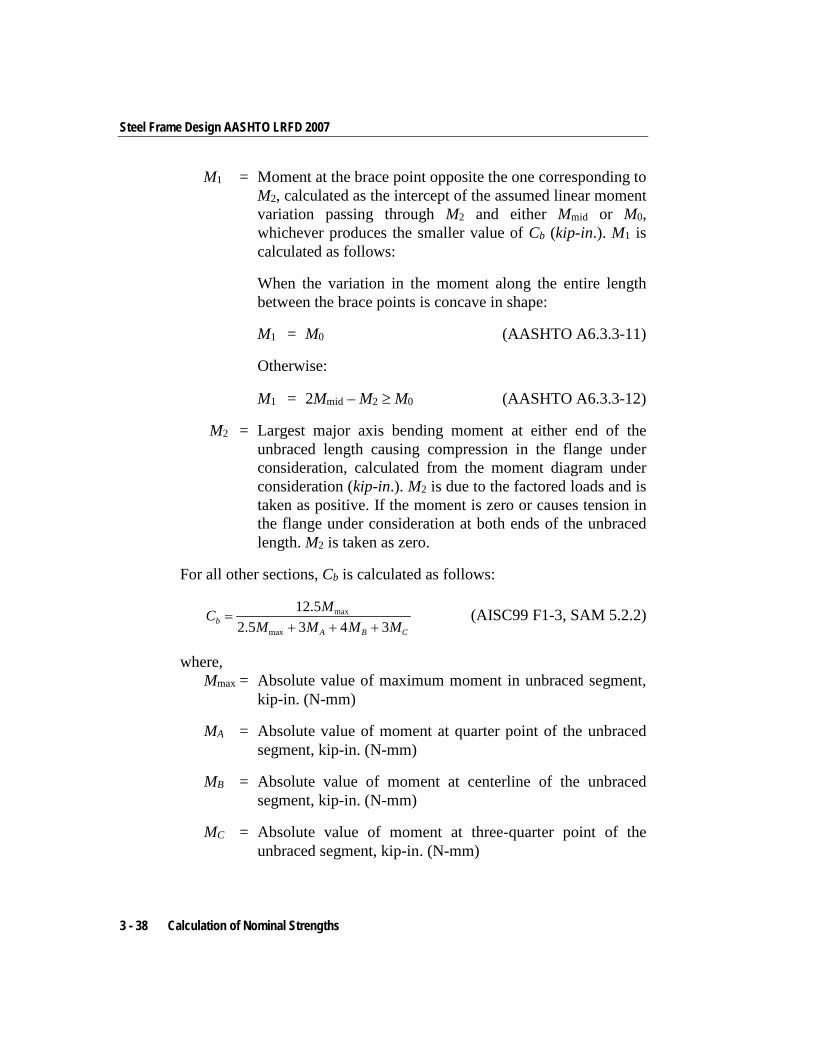
Steel Frame Design AASHTO LRFD 2007
M1 = Moment at the brace point opposite the one corresponding to M2, calculated as the intercept of the assumed linear moment variation passing through M2 and either Mmid or M0, whichever produces the smaller value of Cb (kip-in.). M1 is calculated as follows:
When the variation in the moment along the entire length between the brace points is concave in shape:
M1 = M0 (AASHTO A6.3.3-11)
Otherwise:
M1 = 2Mmid – M2 ≥ M0 (AASHTO A6.3.3-12)
M2 = Largest major axis bending moment at either end of the unbraced length causing compression in the flange under consideration, calculated from the moment diagram under consideration (kip-in.). M2 is due to the factored loads and is taken as positive. If the moment is zero or causes tension in the flange under consideration at both ends of the unbraced length. M2 is taken as zero.
For all other sections, Cb is calculated as follows:
max
max
12.52.5 3 4 3b
A B C
MCM M M M
=+ + +
(AISC99 F1-3, SAM 5.2.2)
where, Mmax = Absolute value of maximum moment in unbraced segment,
kip-in. (N-mm)
MA = Absolute value of moment at quarter point of the unbraced segment, kip-in. (N-mm)
MB = Absolute value of moment at centerline of the unbraced segment, kip-in. (N-mm)
MC = Absolute value of moment at three-quarter point of the unbraced segment, kip-in. (N-mm)
3 - 38 Calculation of Nominal Strengths
Chapter 3 - Check/Design Using AASHTO LRFD 07
Cb should be taken as 1.0 for cantilevers. However, the program is unable to detect whether the member is a cantilever. The user should overwrite Cb for cantilevers. The program also defaults Cb to 1.0 if the minor unbraced length, l22, is redefined to be more than the length of the member by the user or the program, i.e., if the unbraced length is longer than the member length. The Overwrites can be used to change the value of Cb for any member.
The nominal bending strength depends on the following criteria: the geometric shape of the cross-section; the axis of bending; the compactness of the section; and a slenderness parameter for lateral-torsional buckling. The nominal bending strength is the minimum value obtained according to the limit states of yielding, lateral-torsional buckling, flange local buckling, web local buckling, tension flange yielding as appropriate to different structural shapes. The following sections describe how different members are designed against flexure.
3.7.3.1 I Sections
3.7.3.1.1 Major Axis Bending The program calculates the moment capacity in accordance with section 6.10.6.2 of the code. For noncomposite I-Sections, the code allows the use of Appendix A as an alternative path (AASHTO C6.10.8.1.1) provided that the section satisfies certain conditions as prescribed in AASHTO 6.10.6.2.3 and A6.1. The program uses this alternative path instead of the main code section AASHTO 6.10.8. The appendix is based on moments or stress resultants instead of flange or web stresses.
The following material strength and geometric conditions should be satisfied by the member (AASHTO C6.10.8.1.1, 6.10.6.2.3, A6.1):
(a) The specified minimum yield strengths of the flanges and web should not exceed 70.0 ksi,
fy ≤ 70 ksi (AASHTO C6.10.8.1.1, 6.10.6.2.3, A6.1)
(b) The web should be either compact or noncompact. If should not be slender.
Calculation of Nominal Strengths 3 - 39
Steel Frame Design AASHTO LRFD 2007
2 5.7 ,c
w yc
D Et F
< and(AASHTO C6.10.8.1.1, 6.10.6.2.3, A6.1-1)
(c) The flanges satisfy the following ratio:
0.3yc
yt
II
≥ (AASHTO C6.10.8.1.1, 6.10.6.2.3, A6.1-2)
where,
Dc = Depth of the web in compression in the elastic range under flexural load only, in. It is taken as the depth of the neutral axis from the free edge of the compression flange minus the thickness of the compression flange.
Dc = yc – tfc, Singly Symmetric I-Shape(AASHTO A6.1, D6.3.1)
Dc = d / 2 – tf, Doubly Symmetric I-Shape(AASHTO A6.1, D6.3.1)
yc = Depth of the neutral axis from the free edge of the compression flange, in.
tfc = Thickness of the compression flange, in.
d = Overall depth of the section, in.
tf = Thickness of the flange, in.
tw = Thickness of the web, in.
Iyc = Moment of inertia of the compression flange of the steel section about the vertical axis in the plane of the web, in4.
Iyt = Moment of inertia of the tension flange of the steel section about the vertical axis in the plane of web, in4.
As mentioned in item (b), the web of the section should be either compact or noncompact. It should definitely not be slender. The compactness is measured by the parameter for λw. The corresponding limits for being compact and noncompact are ( )cpw Dλ and λrw, where
3 - 40 Calculation of Nominal Strengths
Chapter 3 - Check/Design Using AASHTO LRFD 07
λw = 2 c
w
Dt
(AASHTO A6.2.2-2)
λrw = 5.7yc
EF
(AASHTO A6.2.2-3, A6.2.1-3)
( )cpw Dλ = 2
0.54 0.09
c
cp ycrw
p
h y
D ED F
MR M
λ
≤
−
(AASHTO A6.2.1-2, A6.2.2-6)
There is an alternative slenderness parameter ( )cpw Dλ and corresponding limit ( )cppw Dλ for compact sections. These parameters can also be used equivalently to the previous parameters.
( )2
cp
cpw D
w
Dt
λ = (AASHTO 6.2.1)
( ) 2
0.54 0.09cp
yc cprwpw D
cp
h y
EF D
DMR M
λ λ
= ≤
−
(AASHTO A6.2.1-2)
where,
Dc = Depth of the web in compression in the elastic range under pure flexural load only, in. It is described in detail previously in this chapter.
Dcp = Depth of the web in compression at the plastic moment under pure flexural load only, in. It is taken as the depth of the plastic neutral axis from the free edge of the compression flange minus the thickness of the compression flange.
Dcp = yp – tfc, Singly Symmetric I-Shape(AASHTO A6.1, D6.3.2)
Dcp = d / 2 – tfc, Doubly Symmetric I-Shape(AASHTO A6.1, D6.3.1)
Calculation of Nominal Strengths 3 - 41
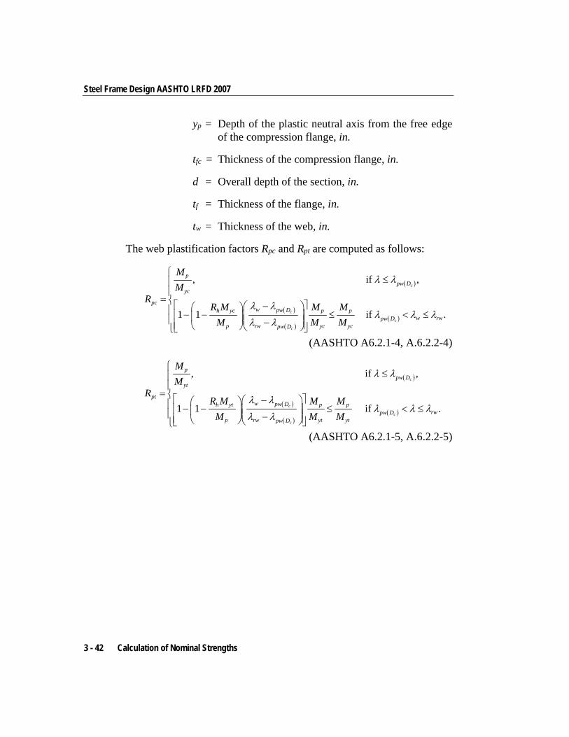
Steel Frame Design AASHTO LRFD 2007
yp = Depth of the plastic neutral axis from the free edge of the compression flange, in.
tfc = Thickness of the compression flange, in.
d = Overall depth of the section, in.
tf = Thickness of the flange, in.
tw = Thickness of the web, in.
The web plastification factors Rpc and Rpt are computed as follows:
( )
( )
( )( )
, if ,
1 1 if .
c
c
c
c
ppw D
yc
pcw pw Dh yc p p
w rwpw Dp rw yc ycpw D
MM
RR M M M
M M M
λ λ
λ λλ λ λ
λ λ
≤
= − − − ≤ < ≤ −
(AASHTO A6.2.1-4, A.6.2.2-4)
( )
( )
( )( )
, if ,
1 1 if .
c
c
c
c
ppw D
yt
ptw pw Dh yt p p
rwpw Dp rw yt ytpw D
MM
RR M M M
M M M
λ λ
λ λλ λ λ
λ λ
≤
= − − − ≤ < ≤ −
(AASHTO A6.2.1-5, A.6.2.2-5)
3 - 42 Calculation of Nominal Strengths
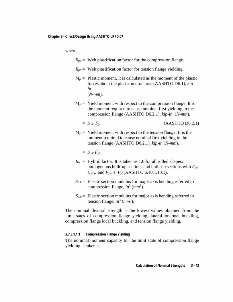
Chapter 3 - Check/Design Using AASHTO LRFD 07
where,
Rpc = Web plastification factor for the compression flange.
Rpt = Web plastification factor for tension flange yielding.
Mp = Plastic moment. It is calculated as the moment of the plastic forces about the plastic neutral axis (AASHTO D6.1), kip-in. (N-mm).
Myc = Yield moment with respect to the compression flange. It is the moment required to cause nominal first yielding in the compression flange (AASHTO D6.2.1), kip-in. (N-mm).
= S33c Fyc (AASHTO D6.2.1)
Myt = Yield moment with respect to the tension flange. It is the moment required to cause nominal first yielding in the tension flange (AASHTO D6.2.1), kip-in (N-mm).
= S33t Fyt
Rh = Hybrid factor. It is taken as 1.0 for all rolled shapes, homogenous built-up sections and built-up sections with Fyw ≥ Fyc and Fyw ≥ Fyt (AASHTO 6.10.1.10.1).
S33c = Elastic section modulus for major axis bending referred to compression flange, in3 (mm3).
S33t = Elastic section modulus for major axis bending referred to tension flange, in3 (mm3).
The nominal flexural strength is the lowest values obtained from the limit sates of compression flange yielding, lateral-torsional buckling, compression flange local buckling, and tension flange yielding.
3.7.3.1.1.1 Compression Flange Yielding The nominal moment capacity for the limit state of compression flange yielding is taken as
Calculation of Nominal Strengths 3 - 43
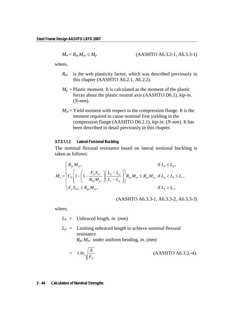
Steel Frame Design AASHTO LRFD 2007
Mn = RpcMyc ≤ Mp (AASHTO A6.3.2-1, A6.3.3-1)
where,
Rpc is the web plasticity factor, which was described previously in this chapter (AASHTO A6.2.1, A6.2.2).
Mp = Plastic moment. It is calculated as the moment of the plastic forces about the plastic neutral axis (AASHTO D6.1), kip-in. (N-mm).
Myc = Yield moment with respect to the compression flange. It is the moment required to cause nominal first yielding in the compression flange (AASHTO D6.2.1), kip-in. (N-mm). It has been described in detail previously in this chapter.
3.7.3.1.1.2 Lateral-Torsional Buckling The nominal flexural resistance based on lateral torsional buckling is taken as follows:
33
, if ,
1 1 if ,
, if ,
pc yc b p
yr xc b pn b pc yc pc yc p b r
pc yc r p
cr c pc yc b r
R M L L
F S L LM C R M R M L L L
R M L L
F S R M L L
≤
− = − − ≤ < ≤ −
≤ >
(AASHTO A6.3.3-1, A6.3.3-2, A6.3.3-3)
where,
Lb = Unbraced length, in. (mm)
Lp = Limiting unbraced length to achieve nominal flexural resistance Rpc Myc under uniform bending, in. (mm)
= 1.0 tyc
ErF
(AASHTO A6.3.3.-4).
3 - 44 Calculation of Nominal Strengths
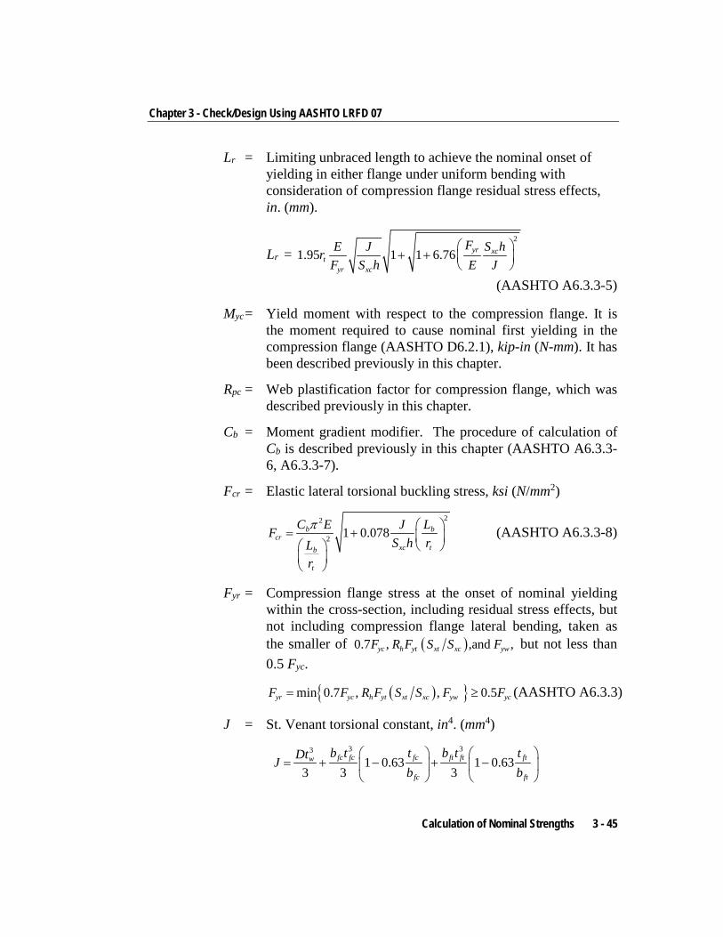
Chapter 3 - Check/Design Using AASHTO LRFD 07
Lr = Limiting unbraced length to achieve the nominal onset of yielding in either flange under uniform bending with consideration of compression flange residual stress effects, in. (mm).
Lr = 2
1.95 1 1 6.76 yr xct
yr xc
FE J S hrF S h E J
+ +
(AASHTO A6.3.3-5)
Myc = Yield moment with respect to the compression flange. It is the moment required to cause nominal first yielding in the compression flange (AASHTO D6.2.1), kip-in (N-mm). It has been described previously in this chapter.
Rpc = Web plastification factor for compression flange, which was described previously in this chapter.
Cb = Moment gradient modifier. The procedure of calculation of Cb is described previously in this chapter (AASHTO A6.3.3-6, A6.3.3-7).
Fcr = Elastic lateral torsional buckling stress, ksi (N/mm2)
22
2 1 0.078b bcr
xc tb
t
C E J LFS h rL
r
π = +
(AASHTO A6.3.3-8)
Fyr = Compression flange stress at the onset of nominal yielding within the cross-section, including residual stress effects, but not including compression flange lateral bending, taken as the smaller of ( )0.7 , ,and ,yc h yt xt xc ywF R F S S F but not less than 0.5 Fyc.
( ){ }min 0.7 , , 0.5yr yc h yt xt xc yw ycF F R F S S F F= ≥ (AASHTO A6.3.3)
J = St. Venant torsional constant, in4. (mm4) 3 33
1 0.63 1 0.633 3 3
fc fc fc ft ft ftw
fc ft
b t t b t tDtJb b
= + − + −
Calculation of Nominal Strengths 3 - 45
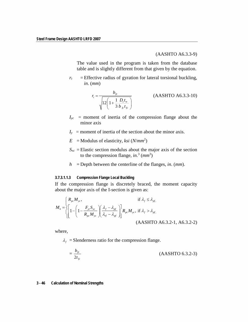
Steel Frame Design AASHTO LRFD 2007
(AASHTO A6.3.3-9)
The value used in the program is taken from the database table and is slightly different from that given by the equation.
rt = Effective radius of gyration for lateral torsional buckling, in. (mm)
112 13
fct
c w
fc fc
br
D tb t
= +
(AASHTO A6.3.3-10)
Iyc = moment of inertia of the compression flange about the minor axis
Iy = moment of inertia of the section about the minor axis.
E = Modulus of elasticity, ksi (N/mm2)
Sxc = Elastic section modulus about the major axis of the section to the compression flange, in.3 (mm3)
h = Depth between the centerline of the flanges, in. (mm).
3.7.3.1.1.3 Compression Flange Local Buckling If the compression flange is discretely braced, the moment capacity about the major axis of the I-section is given as:
,
,
, if
1 1 , if
pc yc f pf
n yr xc f pfpc yc f pf
pc yc rf pf
R M
M F SR M
R M
λ λ
λ λλ λ
λ λ
≤
= − − − > −
(AASHTO A6.3.2-1, A6.3.2-2)
where,
fλ = Slenderness ratio for the compression flange.
= 2
fc
fc
bt
(AASHTO 6.3.2-3)
3 - 46 Calculation of Nominal Strengths
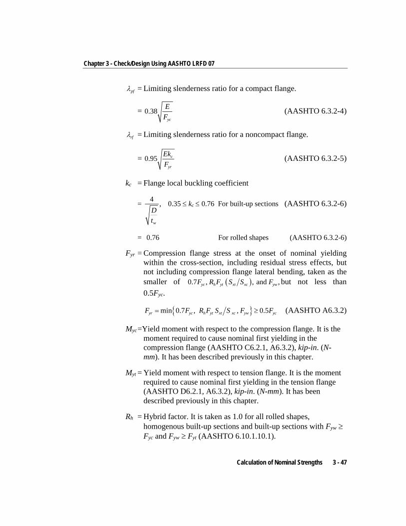
Chapter 3 - Check/Design Using AASHTO LRFD 07
pfλ = Limiting slenderness ratio for a compact flange.
= 0.38yc
EF
(AASHTO 6.3.2-4)
rfλ = Limiting slenderness ratio for a noncompact flange.
= 0.95 c
yr
EkF
(AASHTO 6.3.2-5)
kc = Flange local buckling coefficient
= 4 ,
w
Dt
0.35 ≤ kc ≤ 0.76 For built-up sections (AASHTO 6.3.2-6)
= 0.76 For rolled shapes (AASHTO 6.3.2-6)
Fyr = Compression flange stress at the onset of nominal yielding within the cross-section, including residual stress effects, but not including compression flange lateral bending, taken as the smaller of ( )0.7 , , and ,yc h yt xt xc ywF R F S S F but not less than 0.5Fyc.
{ }min 0.7 , , 0.5yr yc h yt xt xc yw ycF F R F S S F F= ≥ (AASHTO A6.3.2)
Myc =Yield moment with respect to the compression flange. It is the moment required to cause nominal first yielding in the compression flange (AASHTO C6.2.1, A6.3.2), kip-in. (N-mm). It has been described previously in this chapter.
Myt = Yield moment with respect to tension flange. It is the moment required to cause nominal first yielding in the tension flange (AASHTO D6.2.1, A6.3.2), kip-in. (N-mm). It has been described previously in this chapter.
Rh = Hybrid factor. It is taken as 1.0 for all rolled shapes, homogenous built-up sections and built-up sections with Fyw ≥ Fyc and Fyw ≥ Fyt (AASHTO 6.10.1.10.1).
Calculation of Nominal Strengths 3 - 47
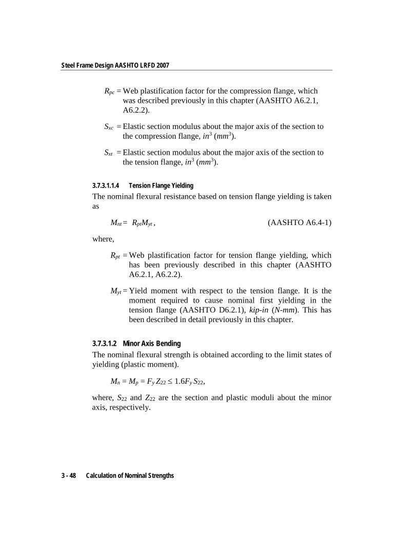
Steel Frame Design AASHTO LRFD 2007
Rpc = Web plastification factor for the compression flange, which was described previously in this chapter (AASHTO A6.2.1, A6.2.2).
Sxc = Elastic section modulus about the major axis of the section to the compression flange, in3 (mm3).
Sxt = Elastic section modulus about the major axis of the section to the tension flange, in3 (mm3).
3.7.3.1.1.4 Tension Flange Yielding The nominal flexural resistance based on tension flange yielding is taken as
Mnt = RptMyt , (AASHTO A6.4-1)
where,
Rpt = Web plastification factor for tension flange yielding, which has been previously described in this chapter (AASHTO A6.2.1, A6.2.2).
Myt = Yield moment with respect to the tension flange. It is the moment required to cause nominal first yielding in the tension flange (AASHTO D6.2.1), kip-in (N-mm). This has been described in detail previously in this chapter.
3.7.3.1.2 Minor Axis Bending The nominal flexural strength is obtained according to the limit states of yielding (plastic moment).
Mn = Mp = Fy Z22 ≤ 1.6Fy S22,
where, S22 and Z22 are the section and plastic moduli about the minor axis, respectively.
3 - 48 Calculation of Nominal Strengths
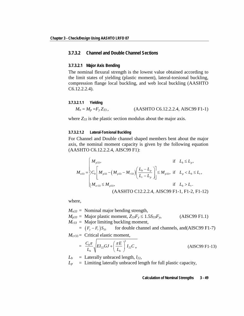
Chapter 3 - Check/Design Using AASHTO LRFD 07
3.7.3.2 Channel and Double Channel Sections
3.7.3.2.1 Major Axis Bending The nominal flexural strength is the lowest value obtained according to the limit states of yielding (plastic moment), lateral-torsional buckling, compression flange local buckling, and web local buckling (AASHTO C6.12.2.2.4).
3.7.3.2.1.1 Yielding Mn = Mp =Fy Z33 , (AASHTO C6.12.2.2.4, AISC99 F1-1)
where Z33 is the plastic section modulus about the major axis.
3.7.3.2.1.2 Lateral-Torsional Buckling For Channel and Double channel shaped members bent about the major axis, the nominal moment capacity is given by the following equation (AASHTO C6.12.2.2.4, AISC99 F1):
( )
33
33 33 33 33 33
33 33
, if ,
, if ,
, if .
p b p
b pn b p p r p p b r
r p
cr p b r
M L L
L LM C M M M M L L L
L L
M M L L
≤ − = − − ≤ < ≤ −
≤ >
(AASHTO C12.2.2.4, AISC99 F1-1, F1-2, F1-12)
where,
Mn33 = Nominal major bending strength, Mp33 = Major plastic moment, Z33Fy ≤ 1.5S33Fy, (AISC99 F1.1) Mr33 = Major limiting buckling moment,
= ( ) 33y rF F S− for double channel and channels, and(AISC99 F1-7) Mcr33 = Critical elastic moment,
= 2
22 22b
wb b
C EEI GJ I CL L
π π +
(AISC99 F1-13)
Lb = Laterally unbraced length, l22, Lp = Limiting laterally unbraced length for full plastic capacity,
Calculation of Nominal Strengths 3 - 49
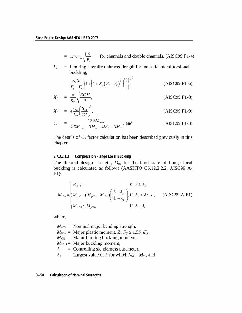
Steel Frame Design AASHTO LRFD 2007
= 221.76y
ErF
for channels and double channels, (AISC99 F1-4)
Lr = Limiting laterally unbraced length for inelastic lateral-torsional buckling,
= ( )1
1 22 222 1
21 1 y ry r
r X X F FF F
+ + − − (AISC99 F1-6)
X1 = 33
,2
EGJASπ (AISC99 F1-8)
X2 = 2
33
22
4 ,wC SI GJ
(AISC99 F1-9)
Cb = max
max
12.5 ,2.5 3 4 3A B C
MM M M M+ + +
and (AISC99 F1-3)
The details of Cb factor calculation has been described previously in this chapter.
3.7.3.2.1.3 Compression Flange Local Buckling The flexural design strength, Mn, for the limit state of flange local buckling is calculated as follows (AASHTO C6.12.2.2.2, AISC99 A-F1):
( )
33
33 33 33 33
33 33
, if ,
, if ,
, if ,
p p
pn p p r p r
r p
cr p r
M
M M M M
M M
λ λ
λ λλ λ λ
λ λ
λ λ
≤
− = − − < ≤ −
≤ >
(AISC99 A-F1)
where,
Mn33 = Nominal major bending strength, Mp33 = Major plastic moment, Z33Fy ≤ 1.5S33Fy, Mr33 = Major limiting buckling moment, Mcr33 = Major buckling moment, λ = Controlling slenderness parameter, λp = Largest value of λ for which Mn = Mp , and
3 - 50 Calculation of Nominal Strengths
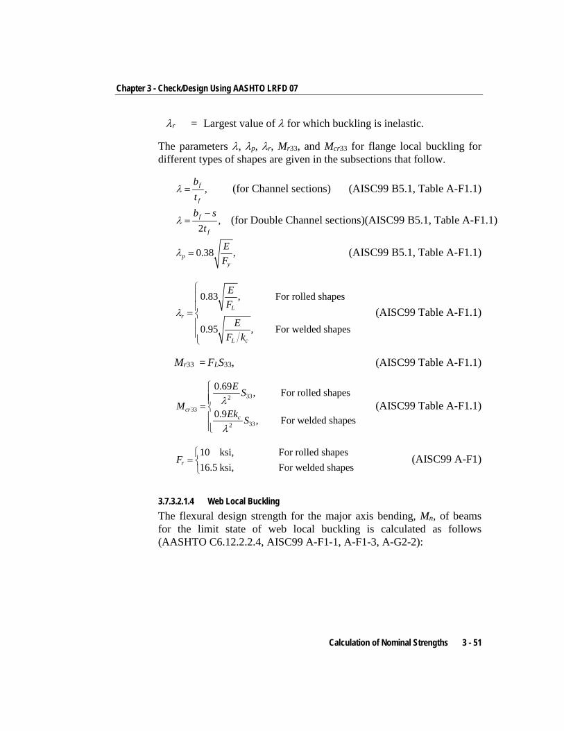
Chapter 3 - Check/Design Using AASHTO LRFD 07
λr = Largest value of λ for which buckling is inelastic.
The parameters λ, λp, λr, Mr33, and Mcr33 for flange local buckling for different types of shapes are given in the subsections that follow.
,f
f
bt
λ = (for Channel sections) (AISC99 B5.1, Table A-F1.1)
,2f
f
b st
λ−
= (for Double Channel sections)(AISC99 B5.1, Table A-F1.1)
0.38 ,py
EF
λ = (AISC99 B5.1, Table A-F1.1)
0.83 , For rolled shapes
0.95 , For welded shapes
Lr
L c
EF
EF k
λ
=
(AISC99 Table A-F1.1)
Mr33 = FLS33, (AISC99 Table A-F1.1)
332
33
332
0.69 , For rolled shapes
0.9 , For welded shapescr
c
E SM
Ek S
λ
λ
=
(AISC99 Table A-F1.1)
10 ksi, For rolled shapes16.5 ksi, For welded shapesrF
=
(AISC99 A-F1)
3.7.3.2.1.4 Web Local Buckling The flexural design strength for the major axis bending, Mn, of beams for the limit state of web local buckling is calculated as follows (AASHTO C6.12.2.2.4, AISC99 A-F1-1, A-F1-3, A-G2-2):
Calculation of Nominal Strengths 3 - 51
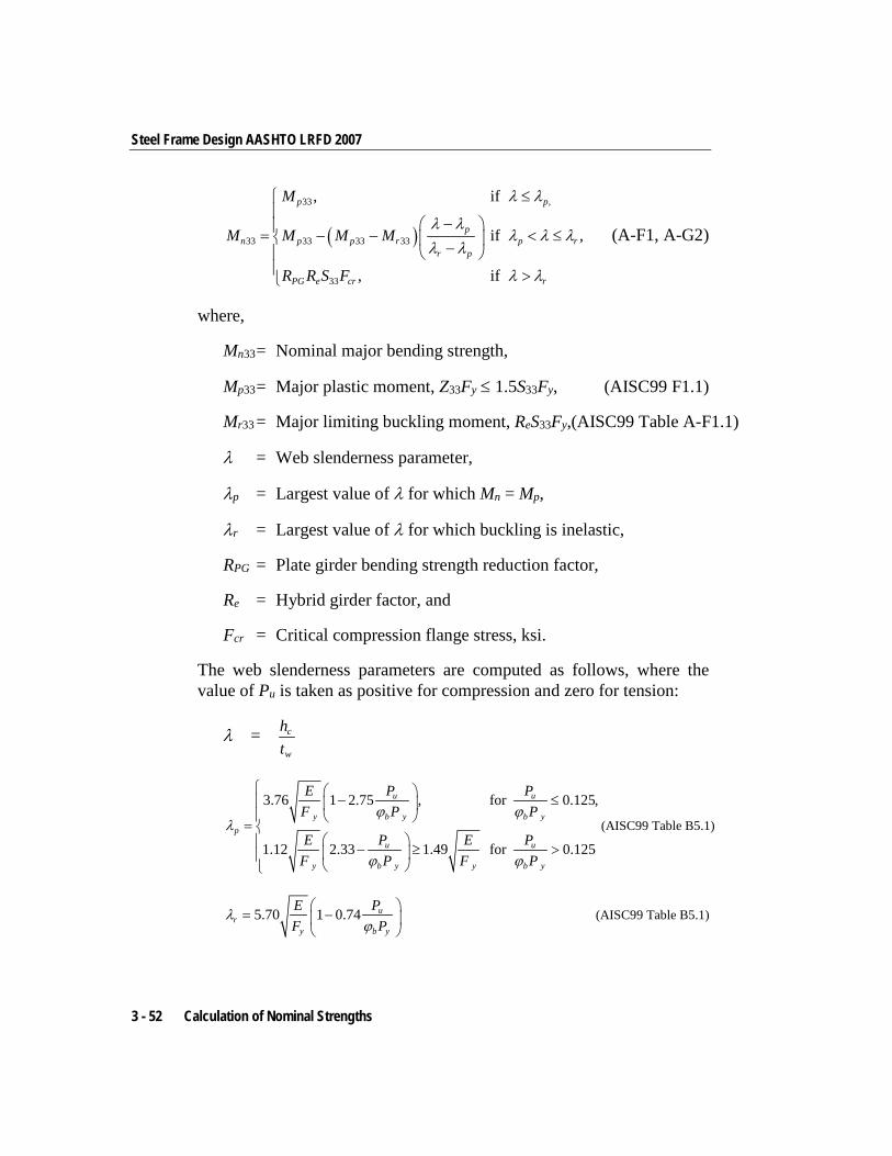
Steel Frame Design AASHTO LRFD 2007
( )
33 ,
33 33 33 33
33
, if
if ,
, if
p p
pn p p r p r
r p
PG e cr r
M
M M M M
R R S F
λ λ
λ λλ λ λ
λ λ
λ λ
≤
− = − − < ≤ − >
(A-F1, A-G2)
where,
Mn33 = Nominal major bending strength,
Mp33 = Major plastic moment, Z33Fy ≤ 1.5S33Fy, (AISC99 F1.1)
Mr33 = Major limiting buckling moment, ReS33Fy,(AISC99 Table A-F1.1)
λ = Web slenderness parameter,
λp = Largest value of λ for which Mn = Mp,
λr = Largest value of λ for which buckling is inelastic,
RPG = Plate girder bending strength reduction factor,
Re = Hybrid girder factor, and
Fcr = Critical compression flange stress, ksi.
The web slenderness parameters are computed as follows, where the value of Pu is taken as positive for compression and zero for tension:
λ = c
w
ht
3.76 1 2.75 , for 0.125,
1.12 2.33 1.49 for 0.125
u u
y b y b yp
u u
y b y y b y
E P PF P P
E P E PF P F P
ϕ ϕλ
ϕ ϕ
− ≤ =
− ≥ >
(AISC99 Table B5.1)
5.70 1 0.74 ur
y b y
E PF P
λϕ
= −
(AISC99 Table B5.1)
3 - 52 Calculation of Nominal Strengths
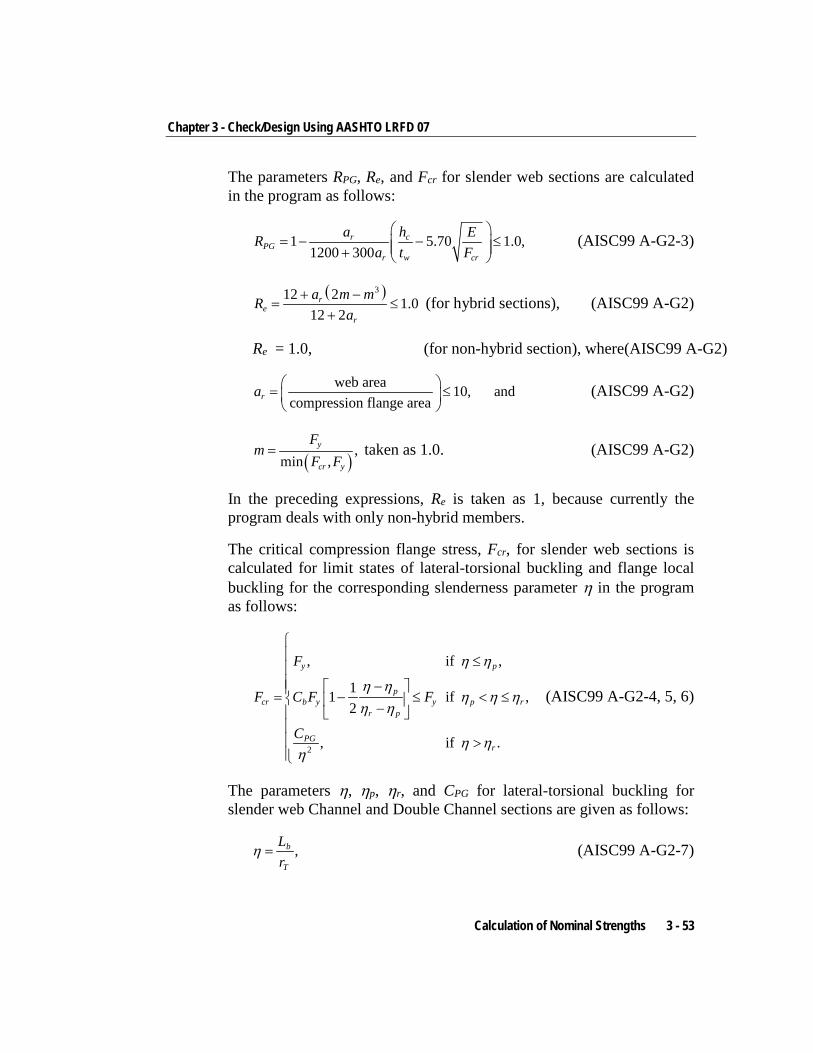
Chapter 3 - Check/Design Using AASHTO LRFD 07
The parameters RPG, Re, and Fcr for slender web sections are calculated in the program as follows:
1 5.70 1.0,1200 300
r cPG
r w cr
a h ERa t F
= − − ≤ +
(AISC99 A-G2-3)
( )312 2 1.012 2
re
r
a m mRa
+ −= ≤
+ (for hybrid sections), (AISC99 A-G2)
Re = 1.0, (for non-hybrid section), where(AISC99 A-G2)
web area 10, andcompression flange areara = ≤
(AISC99 A-G2)
( ),
min ,y
cr y
Fm
F F= taken as 1.0. (AISC99 A-G2)
In the preceding expressions, Re is taken as 1, because currently the program deals with only non-hybrid members.
The critical compression flange stress, Fcr, for slender web sections is calculated for limit states of lateral-torsional buckling and flange local buckling for the corresponding slenderness parameter η in the program as follows:
2
, if ,
11 if ,2
, if .
y p
pcr b y y p r
r p
PGr
F
F C F F
C
η η
η ηη η η
η η
η ηη
≤ − = − ≤ < ≤ − >
(AISC99 A-G2-4, 5, 6)
The parameters η, ηp, ηr, and CPG for lateral-torsional buckling for slender web Channel and Double Channel sections are given as follows:
,b
T
Lr
η = (AISC99 A-G2-7)
Calculation of Nominal Strengths 3 - 53
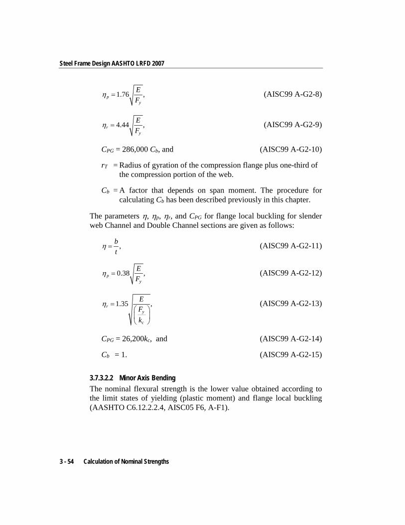
Steel Frame Design AASHTO LRFD 2007
1.76 ,py
EF
η = (AISC99 A-G2-8)
4.44 ,ry
EF
η = (AISC99 A-G2-9)
CPG = 286,000 Cb, and (AISC99 A-G2-10)
rT = Radius of gyration of the compression flange plus one-third of the compression portion of the web.
Cb = A factor that depends on span moment. The procedure for calculating Cb has been described previously in this chapter.
The parameters η, ηp, ηr, and CPG for flange local buckling for slender web Channel and Double Channel sections are given as follows:
,bt
η = (AISC99 A-G2-11)
0.38 ,py
EF
η = (AISC99 A-G2-12)
1.35 ,ry
c
EFk
η =
(AISC99 A-G2-13)
CPG = 26,200kc, and (AISC99 A-G2-14)
Cb = 1. (AISC99 A-G2-15)
3.7.3.2.2 Minor Axis Bending The nominal flexural strength is the lower value obtained according to the limit states of yielding (plastic moment) and flange local buckling (AASHTO C6.12.2.2.4, AISC05 F6, A-F1).
3 - 54 Calculation of Nominal Strengths
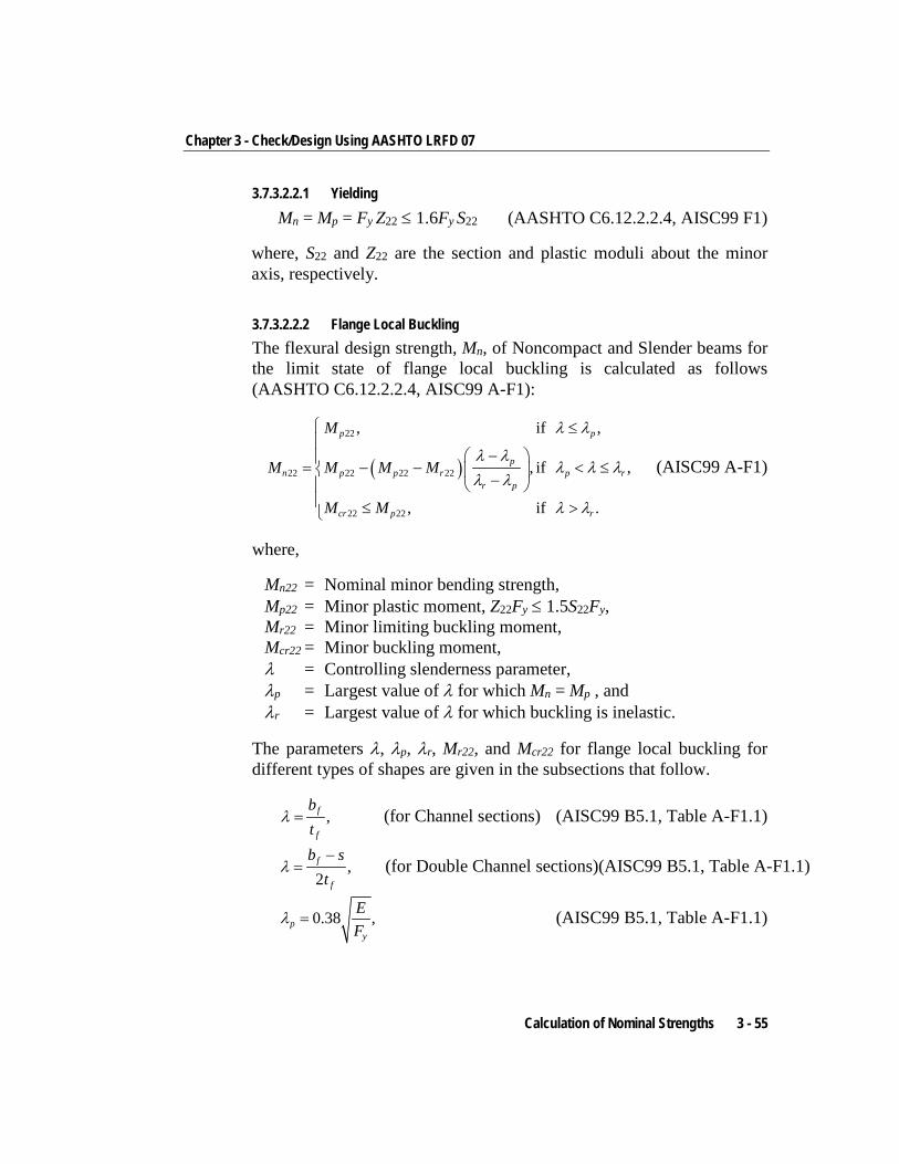
Chapter 3 - Check/Design Using AASHTO LRFD 07
3.7.3.2.2.1 Yielding Mn = Mp = Fy Z22 ≤ 1.6Fy S22 (AASHTO C6.12.2.2.4, AISC99 F1)
where, S22 and Z22 are the section and plastic moduli about the minor axis, respectively.
3.7.3.2.2.2 Flange Local Buckling The flexural design strength, Mn, of Noncompact and Slender beams for the limit state of flange local buckling is calculated as follows (AASHTO C6.12.2.2.4, AISC99 A-F1):
( )
22
22 22 22 22
22 22
, if ,
, if ,
, if .
p p
pn p p r p r
r p
cr p r
M
M M M M
M M
λ λ
λ λλ λ λ
λ λ
λ λ
≤
− = − − < ≤ −
≤ >
(AISC99 A-F1)
where,
Mn22 = Nominal minor bending strength, Mp22 = Minor plastic moment, Z22Fy ≤ 1.5S22Fy, Mr22 = Minor limiting buckling moment, Mcr22 = Minor buckling moment, λ = Controlling slenderness parameter, λp = Largest value of λ for which Mn = Mp , and λr = Largest value of λ for which buckling is inelastic.
The parameters λ, λp, λr, Mr22, and Mcr22 for flange local buckling for different types of shapes are given in the subsections that follow.
,f
f
bt
λ = (for Channel sections) (AISC99 B5.1, Table A-F1.1)
,2f
f
b st
λ−
= (for Double Channel sections)(AISC99 B5.1, Table A-F1.1)
0.38 ,py
EF
λ = (AISC99 B5.1, Table A-F1.1)
Calculation of Nominal Strengths 3 - 55
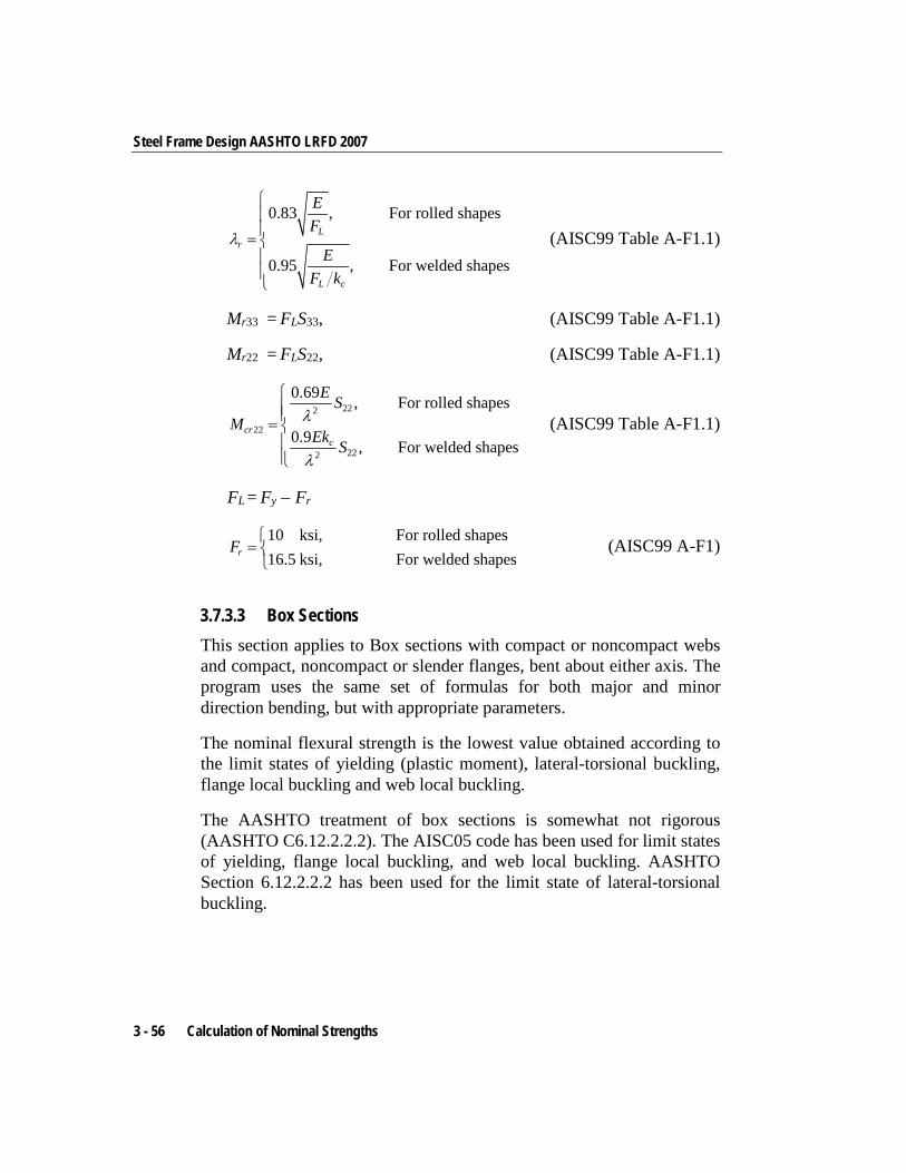
Steel Frame Design AASHTO LRFD 2007
0.83 , For rolled shapes
0.95 , For welded shapes
Lr
L c
EF
EF k
λ
=
(AISC99 Table A-F1.1)
Mr33 = FLS33, (AISC99 Table A-F1.1)
Mr22 = FLS22, (AISC99 Table A-F1.1)
222
22
222
0.69 , For rolled shapes
0.9 , For welded shapescr
c
E SM
Ek S
λ
λ
=
(AISC99 Table A-F1.1)
FL = Fy − Fr
10 ksi, For rolled shapes16.5 ksi, For welded shapesrF
=
(AISC99 A-F1)
3.7.3.3 Box Sections This section applies to Box sections with compact or noncompact webs and compact, noncompact or slender flanges, bent about either axis. The program uses the same set of formulas for both major and minor direction bending, but with appropriate parameters.
The nominal flexural strength is the lowest value obtained according to the limit states of yielding (plastic moment), lateral-torsional buckling, flange local buckling and web local buckling.
The AASHTO treatment of box sections is somewhat not rigorous (AASHTO C6.12.2.2.2). The AISC05 code has been used for limit states of yielding, flange local buckling, and web local buckling. AASHTO Section 6.12.2.2.2 has been used for the limit state of lateral-torsional buckling.
3 - 56 Calculation of Nominal Strengths
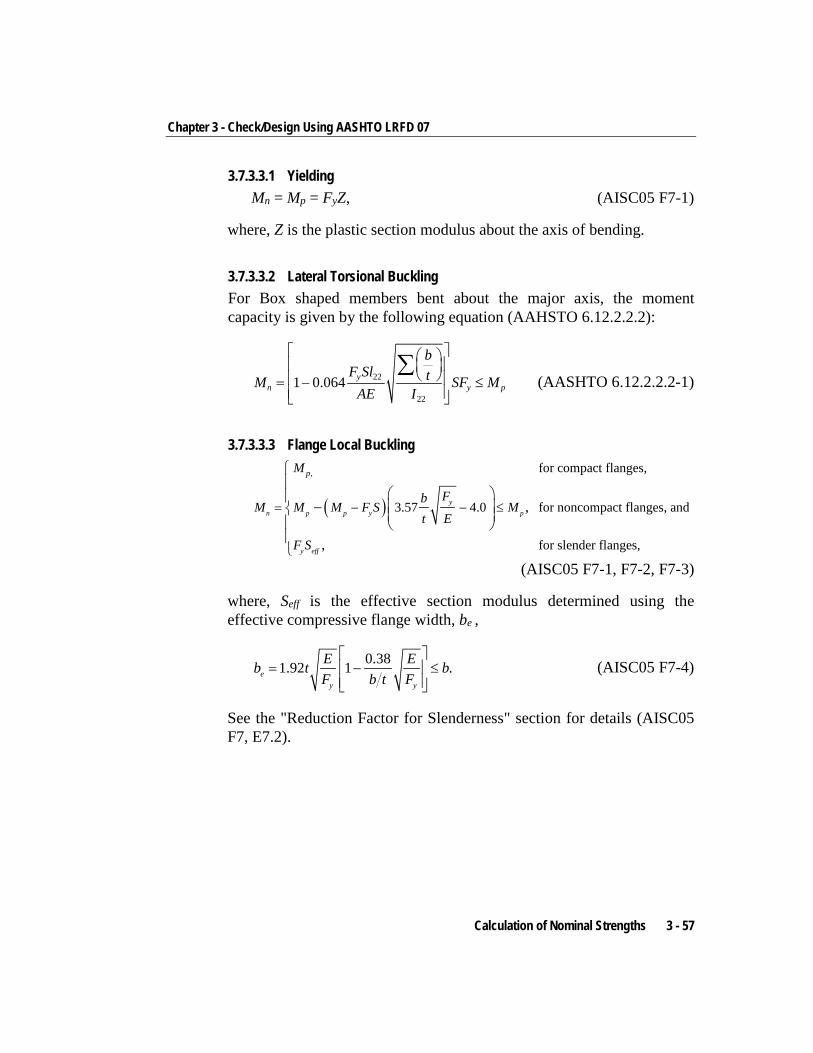
Chapter 3 - Check/Design Using AASHTO LRFD 07
3.7.3.3.1 Yielding Mn = Mp = FyZ, (AISC05 F7-1)
where, Z is the plastic section modulus about the axis of bending.
3.7.3.3.2 Lateral Torsional Buckling For Box shaped members bent about the major axis, the moment capacity is given by the following equation (AAHSTO 6.12.2.2.2):
22
22
1 0.064 yn y p
bF Sl tM SF M
AE I
= − ≤
∑ (AASHTO 6.12.2.2.2-1)
3.7.3.3.3 Flange Local Buckling
( )
, for compact flanges,
3.57 4.0 for noncompact flanges, and
for slender flanges,
,
,
yn p p y p
y eff
pM
FbM M M F S M
t E
F S
= − − ≤
−
(AISC05 F7-1, F7-2, F7-3)
where, Seff is the effective section modulus determined using the effective compressive flange width, be ,
0.381.92 1 .ey y
E Eb t bF b t F
= − ≤
(AISC05 F7-4)
See the "Reduction Factor for Slenderness" section for details (AISC05 F7, E7.2).
Calculation of Nominal Strengths 3 - 57
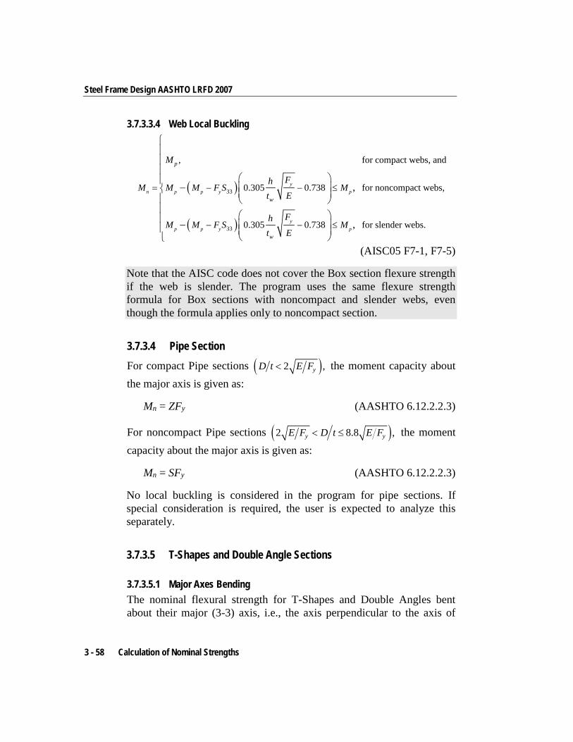
Steel Frame Design AASHTO LRFD 2007
3.7.3.3.4 Web Local Buckling
( )
( )
33
33
, for compact webs, and
0.305 0.738 for noncompact webs,
0.305 0.738 for slender webs.
,
,
yn p p y p
yp p y p
p
w
w
M
FhM M M F S M
t E
FhM M F S M
t E
= − − ≤
− − ≤
−
−
(AISC05 F7-1, F7-5)
Note that the AISC code does not cover the Box section flexure strength if the web is slender. The program uses the same flexure strength formula for Box sections with noncompact and slender webs, even though the formula applies only to noncompact section.
3.7.3.4 Pipe Section For compact Pipe sections ( )2 ,yD t E F< the moment capacity about the major axis is given as:
Mn = ZFy (AASHTO 6.12.2.2.3)
For noncompact Pipe sections ( )2 8.8 ,y yE F D t E F< ≤ the moment capacity about the major axis is given as:
Mn = SFy (AASHTO 6.12.2.2.3)
No local buckling is considered in the program for pipe sections. If special consideration is required, the user is expected to analyze this separately.
3.7.3.5 T-Shapes and Double Angle Sections
3.7.3.5.1 Major Axes Bending The nominal flexural strength for T-Shapes and Double Angles bent about their major (3-3) axis, i.e., the axis perpendicular to the axis of
3 - 58 Calculation of Nominal Strengths
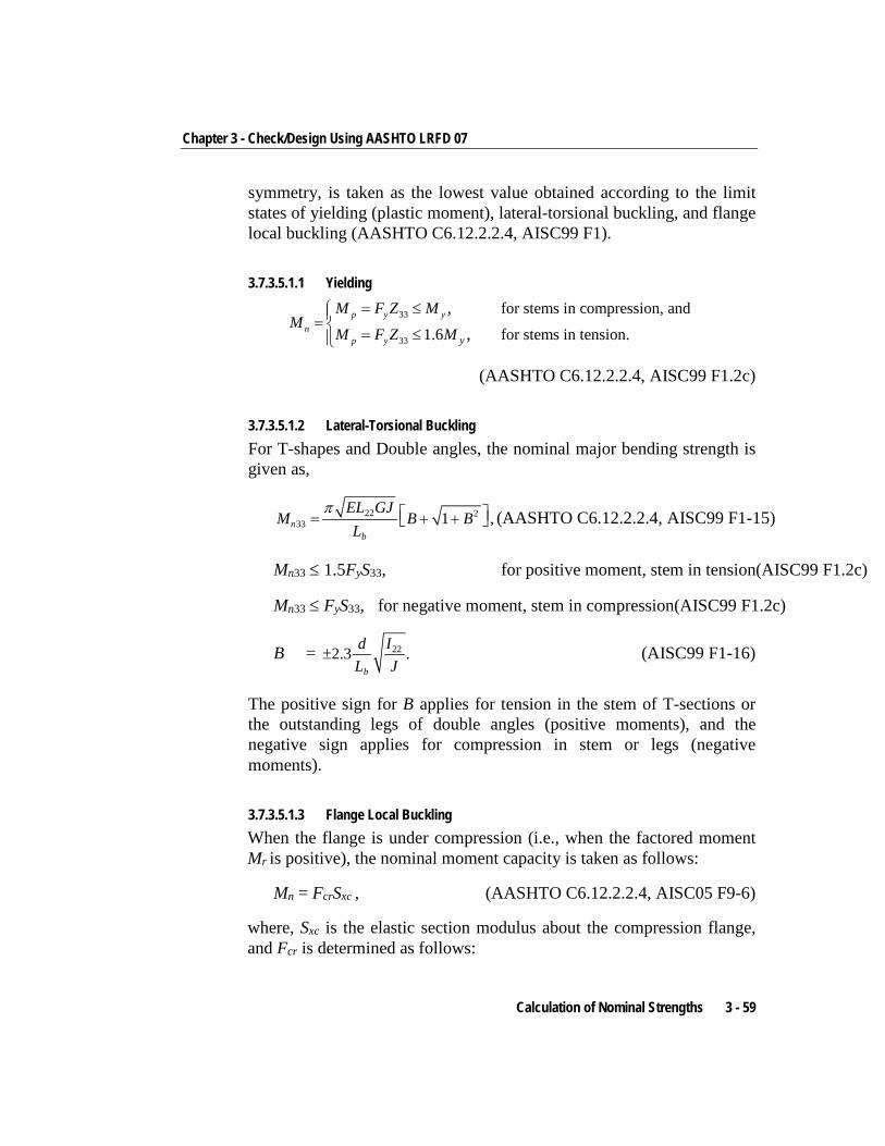
Chapter 3 - Check/Design Using AASHTO LRFD 07
symmetry, is taken as the lowest value obtained according to the limit states of yielding (plastic moment), lateral-torsional buckling, and flange local buckling (AASHTO C6.12.2.2.4, AISC99 F1).
3.7.3.5.1.1 Yielding
33
33
for stems in compression, and
1.6 for stems in tension.,
,= ≤= = ≤
p y yn
p y y
M F Z MM
M F Z M
(AASHTO C6.12.2.2.4, AISC99 F1.2c)
3.7.3.5.1.2 Lateral-Torsional Buckling For T-shapes and Double angles, the nominal major bending strength is given as,
22 233 1 ,n
b
EL GJM B B
Lπ = + + (AASHTO C6.12.2.2.4, AISC99 F1-15)
Mn33 ≤ 1.5FyS33, for positive moment, stem in tension(AISC99 F1.2c)
Mn33 ≤ FyS33, for negative moment, stem in compression(AISC99 F1.2c)
B = 222.3 .b
d IL J
± (AISC99 F1-16)
The positive sign for B applies for tension in the stem of T-sections or the outstanding legs of double angles (positive moments), and the negative sign applies for compression in stem or legs (negative moments).
3.7.3.5.1.3 Flange Local Buckling When the flange is under compression (i.e., when the factored moment Mr is positive), the nominal moment capacity is taken as follows:
Mn = FcrSxc , (AASHTO C6.12.2.2.4, AISC05 F9-6)
where, Sxc is the elastic section modulus about the compression flange, and Fcr is determined as follows:
Calculation of Nominal Strengths 3 - 59
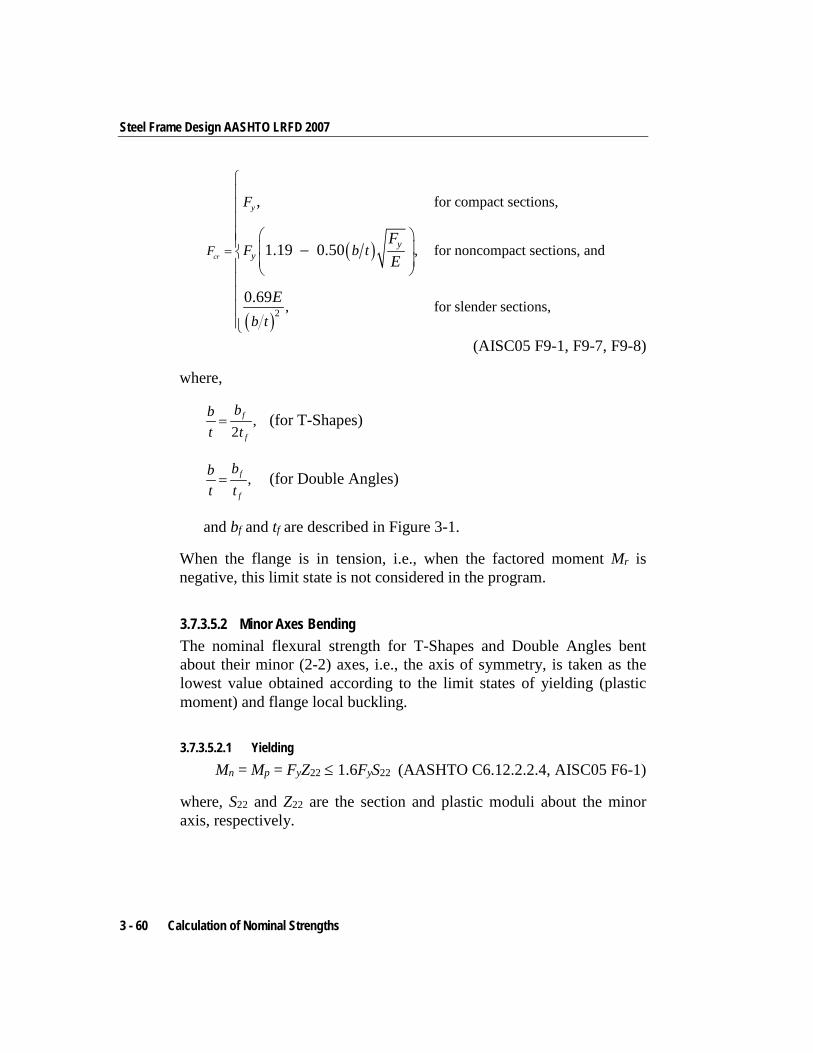
Steel Frame Design AASHTO LRFD 2007
( )
( )2
for compact sections,
, for noncompact sections, and
, for slender sections,
,
1.19 0.50
0.69
cr
y
yyF
F
F b t
b t
FE
E
=
−
(AISC05 F9-1, F9-7, F9-8)
where,
,2
f
f
bbt t
= (for T-Shapes)
,f
f
bbt t
= (for Double Angles)
and bf and tf are described in Figure 3-1.
When the flange is in tension, i.e., when the factored moment Mr is negative, this limit state is not considered in the program.
3.7.3.5.2 Minor Axes Bending The nominal flexural strength for T-Shapes and Double Angles bent about their minor (2-2) axes, i.e., the axis of symmetry, is taken as the lowest value obtained according to the limit states of yielding (plastic moment) and flange local buckling.
3.7.3.5.2.1 Yielding Mn = Mp = FyZ22 ≤ 1.6FyS22 (AASHTO C6.12.2.2.4, AISC05 F6-1)
where, S22 and Z22 are the section and plastic moduli about the minor axis, respectively.
3 - 60 Calculation of Nominal Strengths
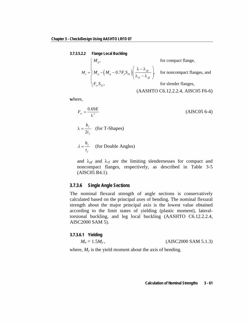
Chapter 3 - Check/Design Using AASHTO LRFD 07
3.7.3.5.2.2 Flange Local Buckling
( )22
22
, for compact flange,
0.7 , for noncompact flanges, and
, for slender flanges,
n
p
pfp p y
rf pf
cr
M
M
M M F S
F S
=
λ − λ− − λ − λ
(AASHTO C6.12.2.2.4, AISC05 F6-6)
where,
2
0.69cr
EF =λ
(AISC05 6-4)
2f
f
bt
λ = (for T-Shapes)
λ = f
f
bt
(for Double Angles)
and λpf and λrf are the limiting slendernesses for compact and noncompact flanges, respectively, as described in Table 3-5 (AISC05 B4.1).
3.7.3.6 Single Angle Sections The nominal flexural strength of angle sections is conservatively calculated based on the principal axes of bending. The nominal flexural strength about the major principal axis is the lowest value obtained according to the limit states of yielding (plastic moment), lateral-torsional buckling, and leg local buckling (AASHTO C6.12.2.2.4, AISC2000 SAM 5).
3.7.3.6.1 Yielding Mn = 1.5My , (AISC2000 SAM 5.1.3)
where, My is the yield moment about the axis of bending.
Calculation of Nominal Strengths 3 - 61
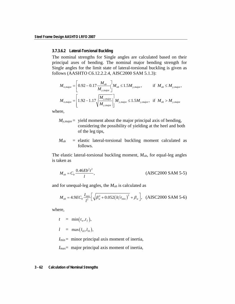
Steel Frame Design AASHTO LRFD 2007
3.7.3.6.2 Lateral-Torsional Buckling The nominal strengths for Single angles are calculated based on their principal axes of bending. The nominal major bending strength for Single angles for the limit state of lateral-torsional buckling is given as follows (AASHTO C6.12.2.2.4, AISC2000 SAM 5.1.3):
,major ,major ,major,major
,major,major ,major ,major ,major
,major
0.92 0.17 1.5 , if ,
1.92 1.17 1.5 , if
obn ob y ob y
y
yn y y ob y
y
MM M M M MM
MM M M M M
M
= − ≤ ≤
= − ≤ >
where,
My,major = yield moment about the major principal axis of bending, considering the possibility of yielding at the heel and both of the leg tips,
Mob = elastic lateral-torsional buckling moment calculated as follows.
The elastic lateral-torsional buckling moment, Mob, for equal-leg angles is taken as
2 20.46 ,ob bEb tM Cl
= (AISC2000 SAM 5-5)
and for unequal-leg angles, the Mob is calculated as
( )22minmin24.9 0.052 ,ob b w w
IM EC lt rl
β β = + + (AISC2000 SAM 5-6)
where,
t = ( )min , ,w ft t
l = ( )22 33max , ,l l
Imin = minor principal axis moment of inertia,
Imax = major principal axis moment of inertia,
3 - 62 Calculation of Nominal Strengths
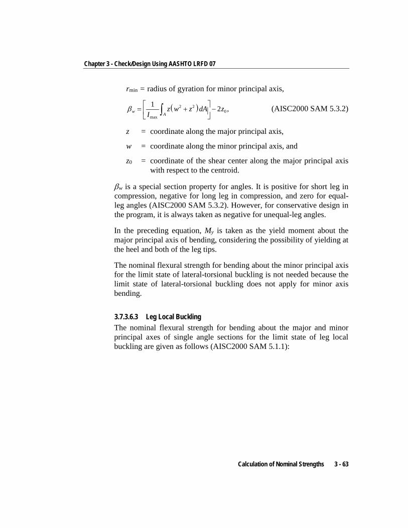
Chapter 3 - Check/Design Using AASHTO LRFD 07
rmin = radius of gyration for minor principal axis,
( )2 20
max
1 2 ,wA
z w z dA zI
β = + − ∫ (AISC2000 SAM 5.3.2)
z = coordinate along the major principal axis,
w = coordinate along the minor principal axis, and
z0 = coordinate of the shear center along the major principal axis with respect to the centroid.
βw is a special section property for angles. It is positive for short leg in compression, negative for long leg in compression, and zero for equal-leg angles (AISC2000 SAM 5.3.2). However, for conservative design in the program, it is always taken as negative for unequal-leg angles.
In the preceding equation, My is taken as the yield moment about the major principal axis of bending, considering the possibility of yielding at the heel and both of the leg tips.
The nominal flexural strength for bending about the minor principal axis for the limit state of lateral-torsional buckling is not needed because the limit state of lateral-torsional buckling does not apply for minor axis bending.
3.7.3.6.3 Leg Local Buckling The nominal flexural strength for bending about the major and minor principal axes of single angle sections for the limit state of leg local buckling are given as follows (AISC2000 SAM 5.1.1):
Calculation of Nominal Strengths 3 - 63
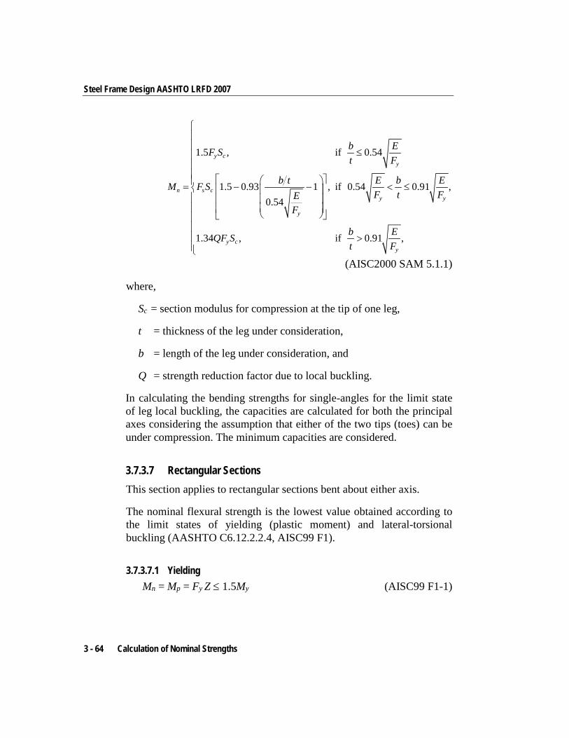
Steel Frame Design AASHTO LRFD 2007
1.5 , if 0.54
1.5 0.93 1 , if 0.54 0.91 ,0.54
1.34 , if 0.91 ,
y cy
n s cy y
y
y cy
b EF St F
b t E b EM F SF t FE
F
b EQF St F
≤ = − − < ≤ >
(AISC2000 SAM 5.1.1)
where,
Sc = section modulus for compression at the tip of one leg,
t = thickness of the leg under consideration,
b = length of the leg under consideration, and
Q = strength reduction factor due to local buckling.
In calculating the bending strengths for single-angles for the limit state of leg local buckling, the capacities are calculated for both the principal axes considering the assumption that either of the two tips (toes) can be under compression. The minimum capacities are considered.
3.7.3.7 Rectangular Sections This section applies to rectangular sections bent about either axis.
The nominal flexural strength is the lowest value obtained according to the limit states of yielding (plastic moment) and lateral-torsional buckling (AASHTO C6.12.2.2.4, AISC99 F1).
3.7.3.7.1 Yielding Mn = Mp = Fy Z ≤ 1.5My (AISC99 F1-1)
3 - 64 Calculation of Nominal Strengths
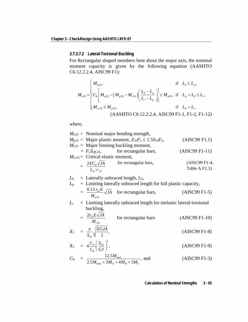
Chapter 3 - Check/Design Using AASHTO LRFD 07
3.7.3.7.2 Lateral-Torsional Buckling For Rectangular shaped members bent about the major axis, the nominal moment capacity is given by the following equation (AASHTO C6.12.2.2.4, AISC99 F1):
( )
33
33 33 33 33 33
33 33
, if ,
, if ,
, if .
p b p
b pn b p p r p p b r
r p
cr p b r
M L L
L LM C M M M M L L L
L L
M M L L
≤ − = − − ≤ < ≤ −
≤ >
(AASHTO C6.12.2.2.4, AISC99 F1-1, F1-2, F1-12)
where,
Mn33 = Nominal major bending strength, Mp33 = Major plastic moment, Z33Fy ≤ 1.5S33Fy, (AISC99 F1.1) Mr33 = Major limiting buckling moment,
= FySeff,33, for rectangular bars, (AISC99 F1-11) Mcr33 = Critical elastic moment,
= 22
2 b
b
EC JAL r
for rectangular bars, (AISC99 F1-4,
Table A F1.1)
Lb = Laterally unbraced length, l22, Lp = Limiting laterally unbraced length for full plastic capacity,
= 22
33
0.13p
r E JAM
for rectangular bars, (AISC99 F1-5)
Lr = Limiting laterally unbraced length for inelastic lateral-torsional buckling,
= 22
33
2r
r E JAM
for rectangular bars (AISC99 F1-10)
X1 = 33
,2
EGJASπ (AISC99 F1-8)
X2 = 2
33
22
4 ,wC SI GJ
(AISC99 F1-9)
Cb = max
max
12.5 ,2.5 3 4 3A B C
MM M M M+ + +
and (AISC99 F1-3)
Calculation of Nominal Strengths 3 - 65
Steel Frame Design AASHTO LRFD 2007
The details of Cb factor calculation have been provided previously in this chapter.
3.7.3.8 Circular Sections Solid Circular Bars are not subjected to lateral-torsional buckling. They are considered to be compact and their nominal moment capacity about the major axis is given by:
Mn = ZFy. (AASHTO C6.12.2.2.4, AISC99 F1-1)
No consideration of local buckling is required for solid circular shapes (AISC99 Table A-F1.1). If special consideration is required, the user is expected to analyze this separately.
3.7.3.9 General Sections and Section Designer Sections For General sections and Section Designer sections, the nominal major and minor direction bending strengths are assumed as:
Mn = My = SFy.
Note: S is used for General Section because LTB and other criteria are unknown.
The program does not check any lateral-torsional buckling, flange local buckling, web local buckling, or tension flange yielding. The program assumptions may not be conservative. The user is expected to calculate the capacity and overwrite it. If special consideration is required, the user is expected to analyze this separately.
3.7.4 Shear Resistance The nominal shear strengths are calculated for shears along the geometric axes for all sections. For I-Shape, Box, Channel, Double Channel, T-Shape, Double Angle, Pipe, Circular and Rectangular sections, the principal axes coincide with their geometric axes. For Angle sections, principal axes do not coincide with their geometric axes.
3 - 66 Calculation of Nominal Strengths
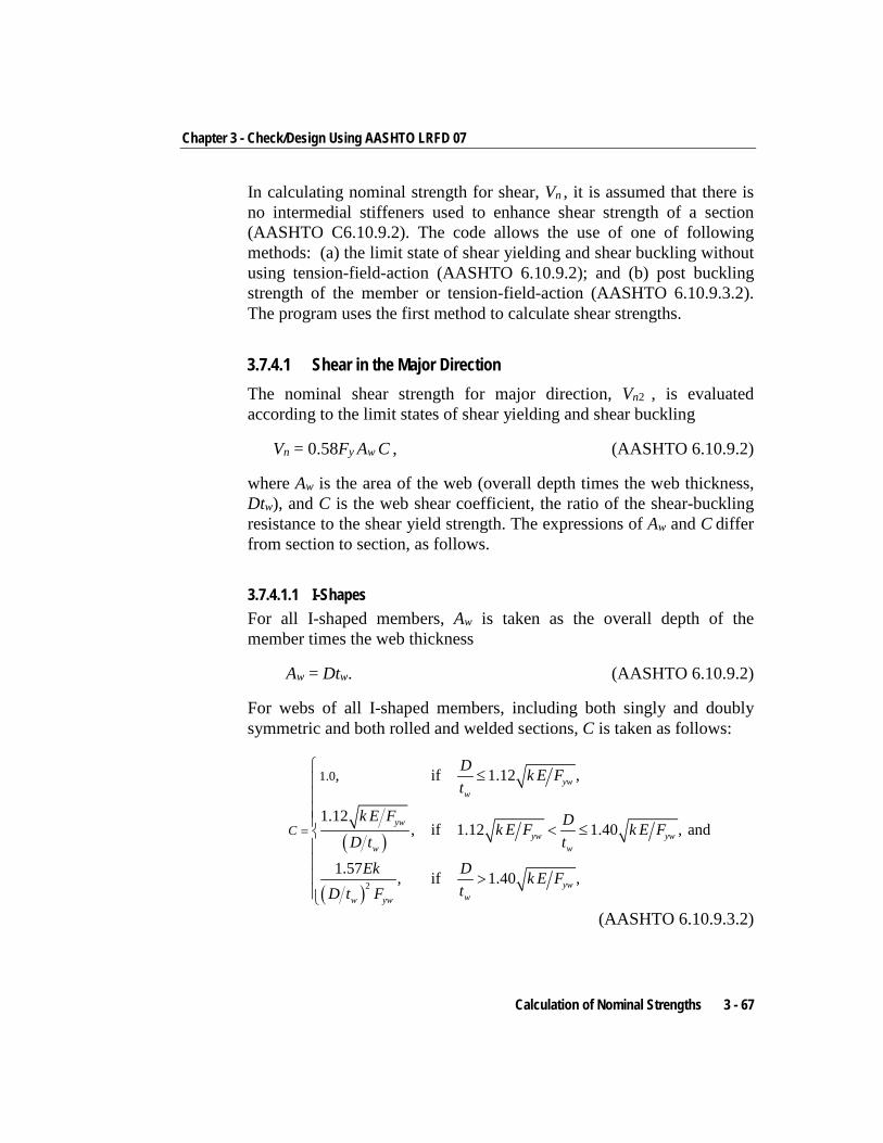
Chapter 3 - Check/Design Using AASHTO LRFD 07
In calculating nominal strength for shear, Vn , it is assumed that there is no intermedial stiffeners used to enhance shear strength of a section (AASHTO C6.10.9.2). The code allows the use of one of following methods: (a) the limit state of shear yielding and shear buckling without using tension-field-action (AASHTO 6.10.9.2); and (b) post buckling strength of the member or tension-field-action (AASHTO 6.10.9.3.2). The program uses the first method to calculate shear strengths.
3.7.4.1 Shear in the Major Direction The nominal shear strength for major direction, Vn2 , is evaluated according to the limit states of shear yielding and shear buckling
Vn = 0.58Fy Aw C , (AASHTO 6.10.9.2)
where Aw is the area of the web (overall depth times the web thickness, Dtw), and C is the web shear coefficient, the ratio of the shear-buckling resistance to the shear yield strength. The expressions of Aw and C differ from section to section, as follows.
3.7.4.1.1 I-Shapes For all I-shaped members, Aw is taken as the overall depth of the member times the web thickness
Aw = Dtw. (AASHTO 6.10.9.2)
For webs of all I-shaped members, including both singly and doubly symmetric and both rolled and welded sections, C is taken as follows:
( )
( )2
1.0, if 1.12 ,
1.12, if 1.12 1.40 , and
1.57 , if 1.40 ,
yww
ywyw yw
w w
ywww yw
C
D k E Ft
k E F Dk E F k E FD t t
Ek D k E FtD t F
=
≤ < ≤ >
(AASHTO 6.10.9.3.2)
Calculation of Nominal Strengths 3 - 67
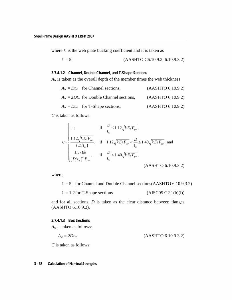
Steel Frame Design AASHTO LRFD 2007
where k is the web plate bucking coefficient and it is taken as
k = 5. (AASHTO C6.10.9.2, 6.10.9.3.2)
3.7.4.1.2 Channel, Double Channel, and T-Shape Sections Aw is taken as the overall depth of the member times the web thickness
Aw = Dtw for Channel sections, (AASHTO 6.10.9.2)
Aw = 2Dtw for Double Channel sections, (AASHTO 6.10.9.2)
Aw = Dtw for T-Shape sections. (AASHTO 6.10.9.2)
C is taken as follows:
( )
( )2
1.0, if 1.12 ,
1.12, if 1.12 1.40 , and
1.57 , if 1.40 ,
yww
ywyw yw
w w
ywww yw
C
D k E Ft
k E F Dk E F k E FD t t
Ek D k E FtD t F
=
≤ < ≤ >
(AASHTO 6.10.9.3.2)
where,
k = 5 for Channel and Double Channel sections(AASHTO 6.10.9.3.2)
k = 1.2 for T-Shape sections (AISC05 G2.1(b)(i))
and for all sections, D is taken as the clear distance between flanges (AASHTO 6.10.9.2).
3.7.4.1.3 Box Sections Aw is taken as follows:
Aw = 2Dtw. (AASHTO 6.10.9.3.2)
C is taken as follows:
3 - 68 Calculation of Nominal Strengths
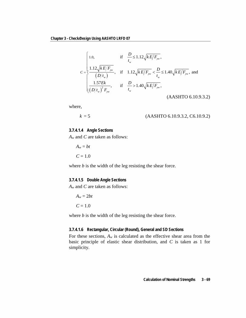
Chapter 3 - Check/Design Using AASHTO LRFD 07
( )
( )2
1.0, if 1.12 ,
1.12, if 1.12 1.40 , and
1.57 , if 1.40 ,
yww
ywyw yw
w w
ywww yw
C
D k E Ft
k E F Dk E F k E FD t t
Ek D k E FtD t F
=
≤ < ≤ >
(AASHTO 6.10.9.3.2)
where,
k = 5 (AASHTO 6.10.9.3.2, C6.10.9.2)
3.7.4.1.4 Angle Sections Aw and C are taken as follows:
Aw = bt
C = 1.0
where b is the width of the leg resisting the shear force.
3.7.4.1.5 Double Angle Sections Aw and C are taken as follows:
Aw = 2bt
C = 1.0
where b is the width of the leg resisting the shear force.
3.7.4.1.6 Rectangular, Circular (Round), General and SD Sections For these sections, Aw is calculated as the effective shear area from the basic principle of elastic shear distribution, and C is taken as 1 for simplicity.
Calculation of Nominal Strengths 3 - 69
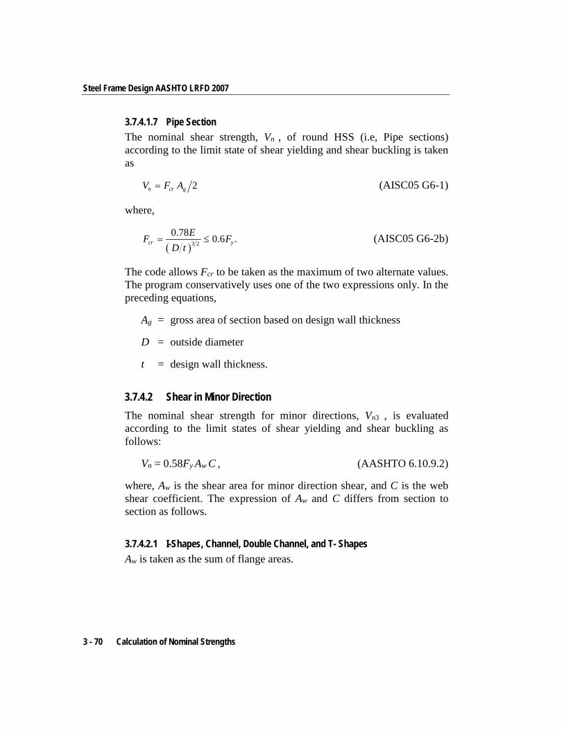
Steel Frame Design AASHTO LRFD 2007
3.7.4.1.7 Pipe Section The nominal shear strength, Vn , of round HSS (i.e, Pipe sections) according to the limit state of shear yielding and shear buckling is taken as
2n cr gV F A= (AISC05 G6-1)
where,
( )3 2
0.78 0.6 .cr yEF F
D t= ≤ (AISC05 G6-2b)
The code allows Fcr to be taken as the maximum of two alternate values. The program conservatively uses one of the two expressions only. In the preceding equations,
Ag = gross area of section based on design wall thickness
D = outside diameter
t = design wall thickness.
3.7.4.2 Shear in Minor Direction The nominal shear strength for minor directions, Vn3 , is evaluated according to the limit states of shear yielding and shear buckling as follows:
Vn = 0.58Fy Aw C , (AASHTO 6.10.9.2)
where, Aw is the shear area for minor direction shear, and C is the web shear coefficient. The expression of Aw and C differs from section to section as follows.
3.7.4.2.1 I-Shapes, Channel, Double Channel, and T- Shapes Aw is taken as the sum of flange areas.
3 - 70 Calculation of Nominal Strengths
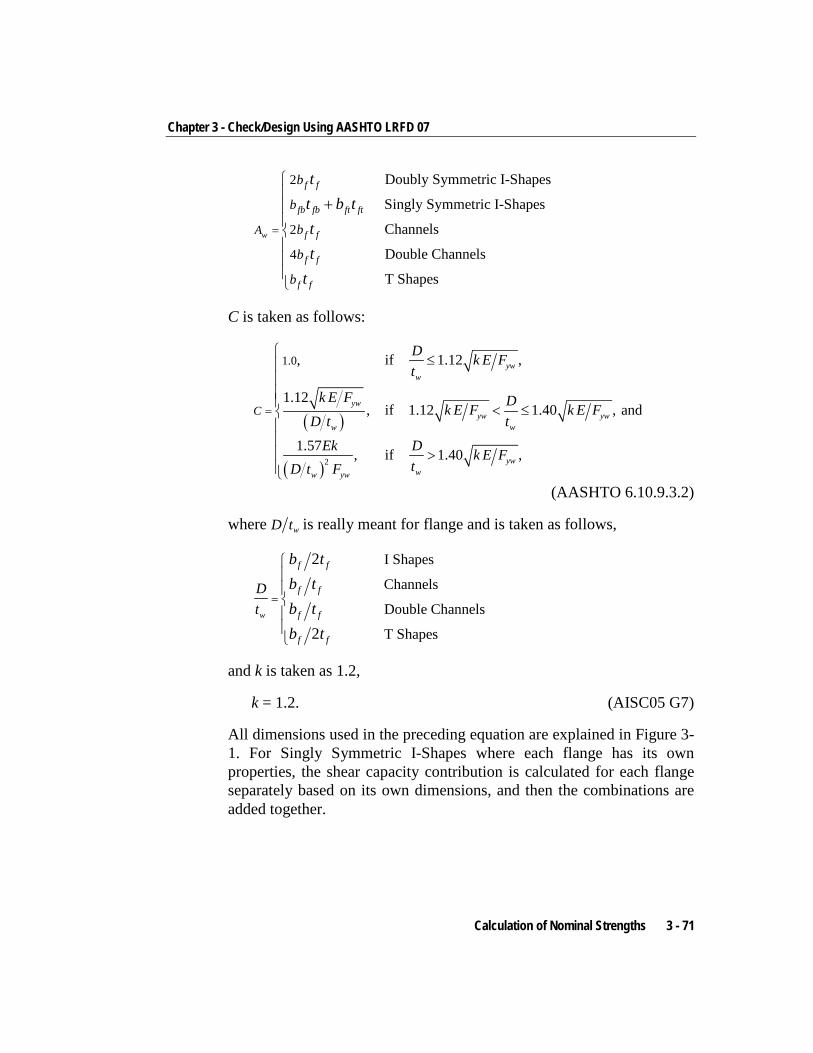
Chapter 3 - Check/Design Using AASHTO LRFD 07
2
2
4
Doubly Symmetric I-Shapes
Singly Symmetric I-Shapes
Channels
Double Channels
T Shapes
w
f f
fb fb ft ft
f f
f f
f f
A
b
b
b
b
b
tt b ttt
t
=
+
C is taken as follows:
( )
( )2
1.0, if 1.12 ,
1.12, if 1.12 1.40 , and
1.57 , if 1.40 ,
yww
ywyw yw
w w
ywww yw
C
D k E Ft
k E F Dk E F k E FD t t
Ek D k E FtD t F
=
≤ < ≤ >
(AASHTO 6.10.9.3.2)
where wD t is really meant for flange and is taken as follows,
I Shapes
Channels
Double Channels
T Shapes
2
2w
f f
f f
f f
f f
Dt
b tb tb tb t
=
and k is taken as 1.2,
k = 1.2. (AISC05 G7)
All dimensions used in the preceding equation are explained in Figure 3-1. For Singly Symmetric I-Shapes where each flange has its own properties, the shear capacity contribution is calculated for each flange separately based on its own dimensions, and then the combinations are added together.
Calculation of Nominal Strengths 3 - 71
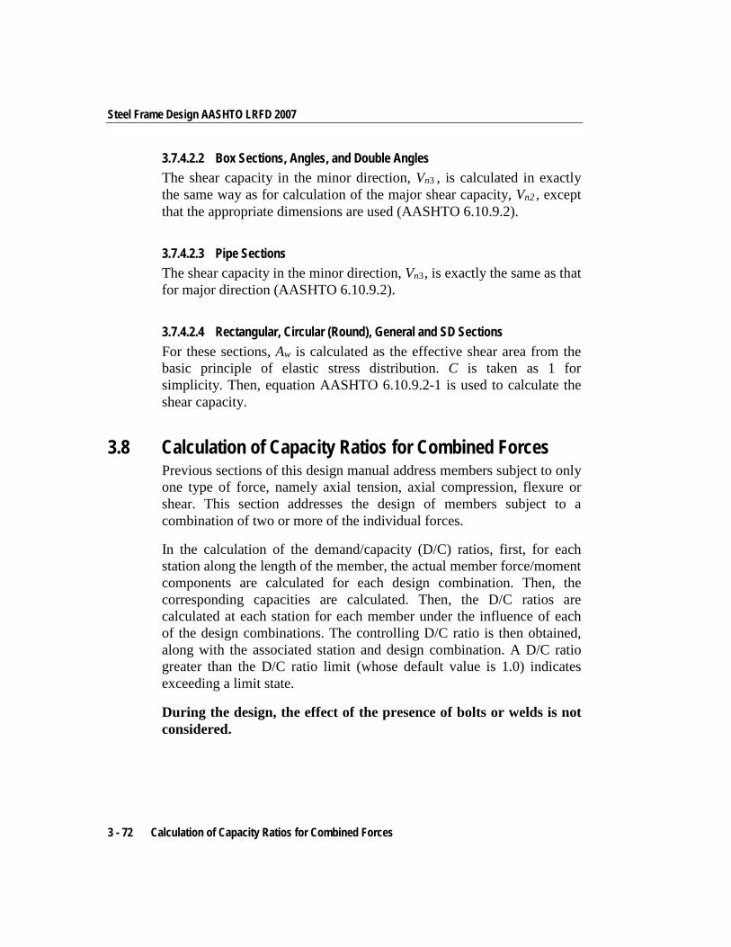
Steel Frame Design AASHTO LRFD 2007
3.7.4.2.2 Box Sections, Angles, and Double Angles The shear capacity in the minor direction, Vn3 , is calculated in exactly the same way as for calculation of the major shear capacity, Vn2 , except that the appropriate dimensions are used (AASHTO 6.10.9.2).
3.7.4.2.3 Pipe Sections The shear capacity in the minor direction, Vn3 , is exactly the same as that for major direction (AASHTO 6.10.9.2).
3.7.4.2.4 Rectangular, Circular (Round), General and SD Sections For these sections, Aw is calculated as the effective shear area from the basic principle of elastic stress distribution. C is taken as 1 for simplicity. Then, equation AASHTO 6.10.9.2-1 is used to calculate the shear capacity.
3.8 Calculation of Capacity Ratios for Combined Forces Previous sections of this design manual address members subject to only one type of force, namely axial tension, axial compression, flexure or shear. This section addresses the design of members subject to a combination of two or more of the individual forces.
In the calculation of the demand/capacity (D/C) ratios, first, for each station along the length of the member, the actual member force/moment components are calculated for each design combination. Then, the corresponding capacities are calculated. Then, the D/C ratios are calculated at each station for each member under the influence of each of the design combinations. The controlling D/C ratio is then obtained, along with the associated station and design combination. A D/C ratio greater than the D/C ratio limit (whose default value is 1.0) indicates exceeding a limit state.
During the design, the effect of the presence of bolts or welds is not considered.
3 - 72 Calculation of Capacity Ratios for Combined Forces
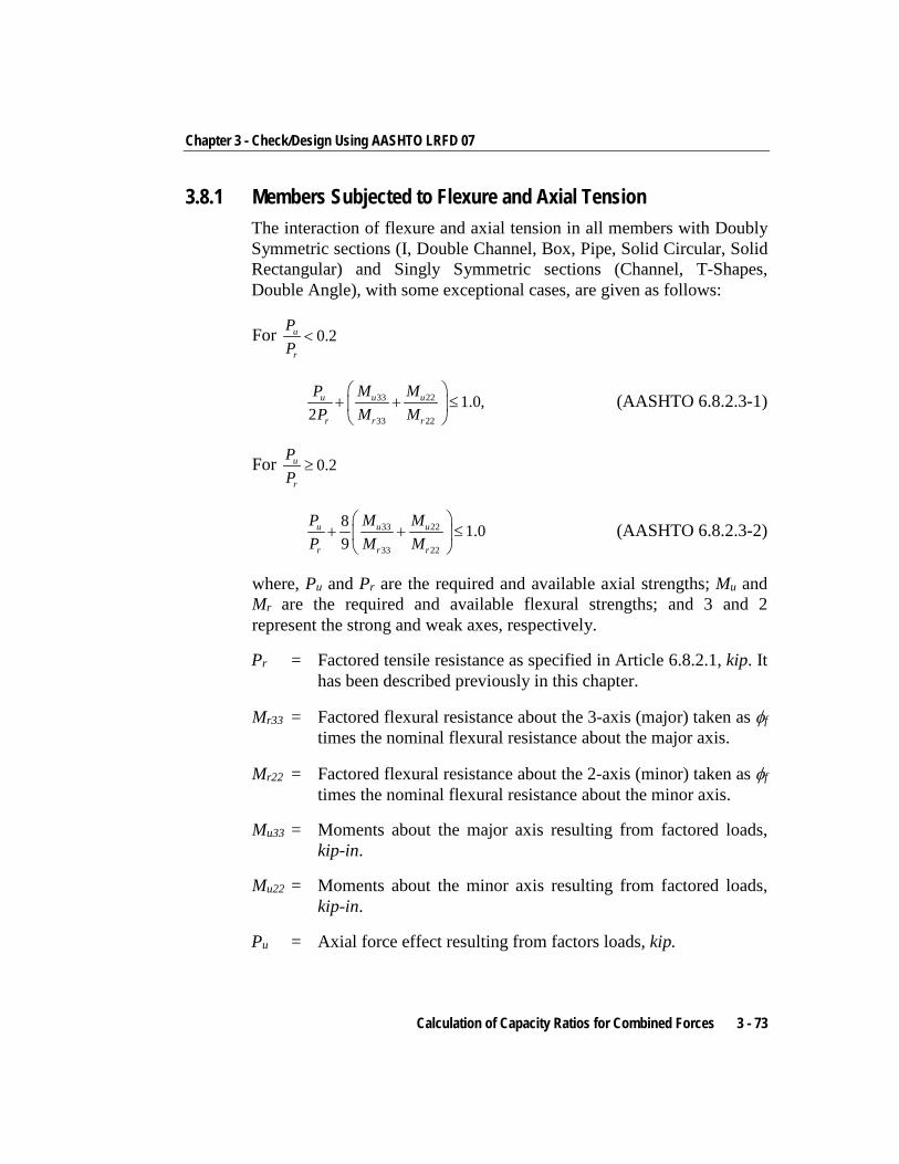
Chapter 3 - Check/Design Using AASHTO LRFD 07
3.8.1 Members Subjected to Flexure and Axial Tension The interaction of flexure and axial tension in all members with Doubly Symmetric sections (I, Double Channel, Box, Pipe, Solid Circular, Solid Rectangular) and Singly Symmetric sections (Channel, T-Shapes, Double Angle), with some exceptional cases, are given as follows:
For 0.2u
r
PP
<
33 22
33 22
1.0,2
u u u
r r r
P M MP M M
+ + ≤
(AASHTO 6.8.2.3-1)
For 0.2u
r
PP
≥
33 22
33 22
8 1.09
u u u
r r r
P M MP M M
+ + ≤
(AASHTO 6.8.2.3-2)
where, Pu and Pr are the required and available axial strengths; Mu and Mr are the required and available flexural strengths; and 3 and 2 represent the strong and weak axes, respectively.
Pr = Factored tensile resistance as specified in Article 6.8.2.1, kip. It has been described previously in this chapter.
Mr33 = Factored flexural resistance about the 3-axis (major) taken as φf times the nominal flexural resistance about the major axis.
Mr22 = Factored flexural resistance about the 2-axis (minor) taken as φf times the nominal flexural resistance about the minor axis.
Mu33 = Moments about the major axis resulting from factored loads, kip-in.
Mu22 = Moments about the minor axis resulting from factored loads, kip-in.
Pu = Axial force effect resulting from factors loads, kip.
Calculation of Capacity Ratios for Combined Forces 3 - 73
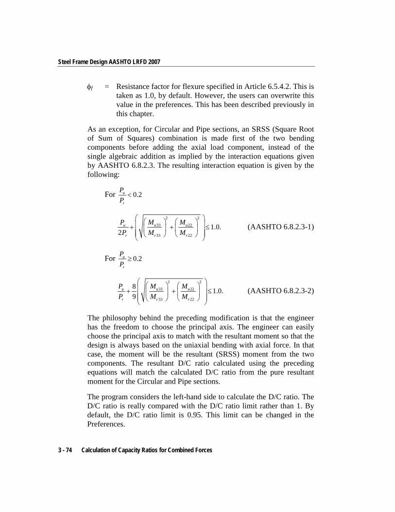
Steel Frame Design AASHTO LRFD 2007
φf = Resistance factor for flexure specified in Article 6.5.4.2. This is taken as 1.0, by default. However, the users can overwrite this value in the preferences. This has been described previously in this chapter.
As an exception, for Circular and Pipe sections, an SRSS (Square Root of Sum of Squares) combination is made first of the two bending components before adding the axial load component, instead of the single algebraic addition as implied by the interaction equations given by AASHTO 6.8.2.3. The resulting interaction equation is given by the following:
For 0.2u
r
PP
<
2 2
33 22
33 22
1.0.2
u u u
r r r
P M MP M M
+ + ≤
(AASHTO 6.8.2.3-1)
For 0.2u
r
PP
≥
2 2
33 22
33 22
8 1.0.9
u u u
r r r
P M MP M M
+ + ≤
(AASHTO 6.8.2.3-2)
The philosophy behind the preceding modification is that the engineer has the freedom to choose the principal axis. The engineer can easily choose the principal axis to match with the resultant moment so that the design is always based on the uniaxial bending with axial force. In that case, the moment will be the resultant (SRSS) moment from the two components. The resultant D/C ratio calculated using the preceding equations will match the calculated D/C ratio from the pure resultant moment for the Circular and Pipe sections.
The program considers the left-hand side to calculate the D/C ratio. The D/C ratio is really compared with the D/C ratio limit rather than 1. By default, the D/C ratio limit is 0.95. This limit can be changed in the Preferences.
3 - 74 Calculation of Capacity Ratios for Combined Forces
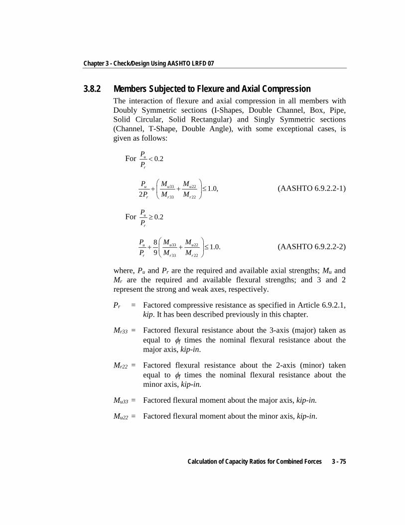
Chapter 3 - Check/Design Using AASHTO LRFD 07
3.8.2 Members Subjected to Flexure and Axial Compression The interaction of flexure and axial compression in all members with Doubly Symmetric sections (I-Shapes, Double Channel, Box, Pipe, Solid Circular, Solid Rectangular) and Singly Symmetric sections (Channel, T-Shape, Double Angle), with some exceptional cases, is given as follows:
For 0.2u
r
PP
<
33 22
33 22
1.0,2
u u u
r r r
P M MP M M
+ + ≤
(AASHTO 6.9.2.2-1)
For 0.2u
r
PP
≥
33 22
33 22
8 1.0.9
u u u
r r r
P M MP M M
+ + ≤
(AASHTO 6.9.2.2-2)
where, Pu and Pr are the required and available axial strengths; Mu and Mr are the required and available flexural strengths; and 3 and 2 represent the strong and weak axes, respectively.
Pr = Factored compressive resistance as specified in Article 6.9.2.1, kip. It has been described previously in this chapter.
Mr33 = Factored flexural resistance about the 3-axis (major) taken as equal to φf times the nominal flexural resistance about the major axis, kip-in.
Mr22 = Factored flexural resistance about the 2-axis (minor) taken equal to φf times the nominal flexural resistance about the minor axis, kip-in.
Mu33 = Factored flexural moment about the major axis, kip-in.
Mu22 = Factored flexural moment about the minor axis, kip-in.
Calculation of Capacity Ratios for Combined Forces 3 - 75
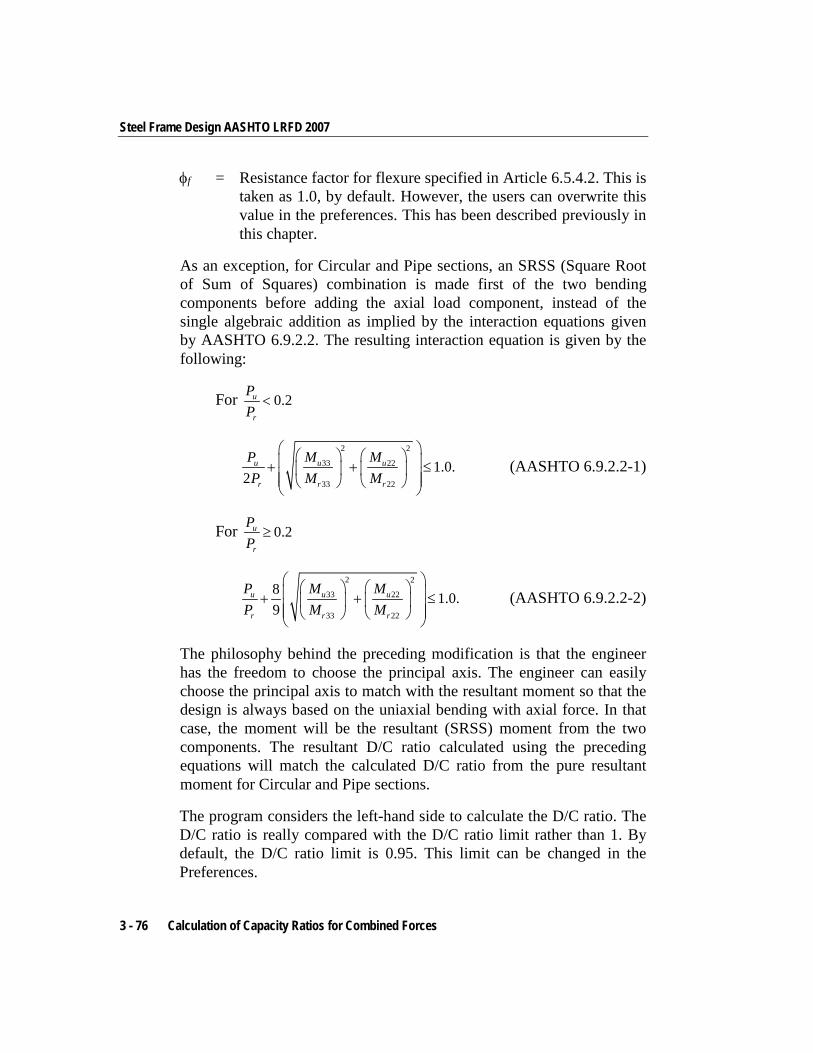
Steel Frame Design AASHTO LRFD 2007
φf = Resistance factor for flexure specified in Article 6.5.4.2. This is taken as 1.0, by default. However, the users can overwrite this value in the preferences. This has been described previously in this chapter.
As an exception, for Circular and Pipe sections, an SRSS (Square Root of Sum of Squares) combination is made first of the two bending components before adding the axial load component, instead of the single algebraic addition as implied by the interaction equations given by AASHTO 6.9.2.2. The resulting interaction equation is given by the following:
For 0.2u
r
PP
<
2 2
33 22
33 22
1.0.2
u u u
r r r
P M MP M M
+ + ≤
(AASHTO 6.9.2.2-1)
For 0.2u
r
PP
≥
2 2
33 22
33 22
8 1.0.9
u u u
r r r
P M MP M M
+ + ≤
(AASHTO 6.9.2.2-2)
The philosophy behind the preceding modification is that the engineer has the freedom to choose the principal axis. The engineer can easily choose the principal axis to match with the resultant moment so that the design is always based on the uniaxial bending with axial force. In that case, the moment will be the resultant (SRSS) moment from the two components. The resultant D/C ratio calculated using the preceding equations will match the calculated D/C ratio from the pure resultant moment for Circular and Pipe sections.
The program considers the left-hand side to calculate the D/C ratio. The D/C ratio is really compared with the D/C ratio limit rather than 1. By default, the D/C ratio limit is 0.95. This limit can be changed in the Preferences.
3 - 76 Calculation of Capacity Ratios for Combined Forces
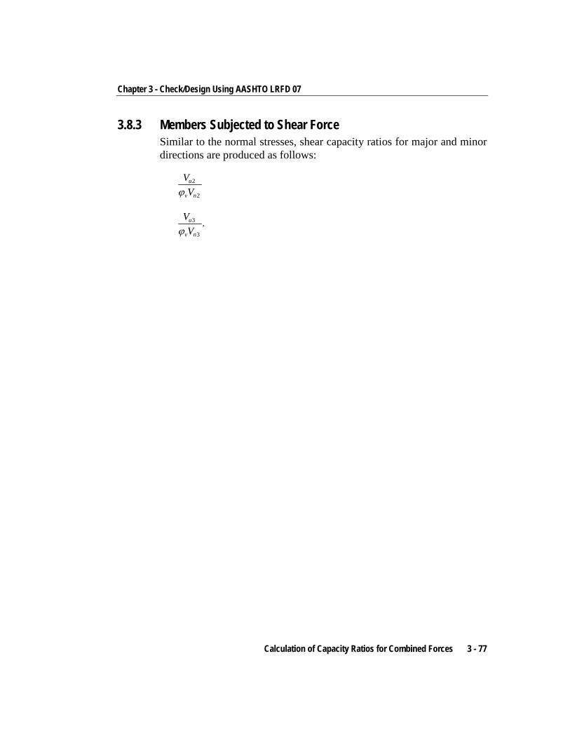
Chapter 3 - Check/Design Using AASHTO LRFD 07
3.8.3 Members Subjected to Shear Force Similar to the normal stresses, shear capacity ratios for major and minor directions are produced as follows:
2
2
u
v n
VVϕ
3
3
.u
v n
VVϕ
Calculation of Capacity Ratios for Combined Forces 3 - 77
Chapter 4 Design Output
4.1 Overview The program has the capacity to create design output in four major ways – graphical display, file output, tabular display, and member specific detailed de-sign information.
The graphical display includes input and output design information for members visible in the active window; the display can be sent directly to a printer or saved to a file. The file output includes both summary and detail design data that can be saved in RTF, HTML and plain text formats. The tabular display output in-cludes both summary and detail design data that can be displayed or saved in many formats, including Excel, Access, RTF, HTML and plain text. The member specific detailed design information shows the details of the calcula-tion.
The following sections describe some of the typical graphical display, file out-put, tabular display output, and member specific detailed design information. Some of the design information is very specific to the chosen steel design code. This manual addresses "AASHTO LRFD 2007" design code related output in-formation only.
4 - 1
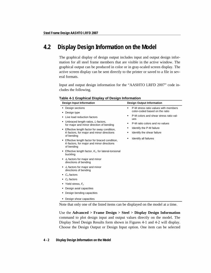
Steel Frame Design AASHTO LRFD 2007
4.2 Display Design Information on the Model The graphical display of design output includes input and output design infor-mation for all steel frame members that are visible in the active window. The graphical output can be produced in color or in gray-scaled screen display. The active screen display can be sent directly to the printer or saved to a file in sev-eral formats.
Input and output design information for the “AASHTO LRFD 2007” code in-cludes the following.
Table 4-1 Graphical Display of Design Information Design Input Information Design Output Information
Design sections Design type Live load reduction factors Unbraced length ratios, L-factors,
for major and minor direction of bending Effective length factor for sway condition,
K-factors, for major and minor directions of bending
Effective length factor for braced condition, K-factors, for major and minor directions of bending
Effective length factor, Kz, for lateral-torsional buckling
δb factors for major and minor directions of bending
δs factors for major and minor directions of bending
Cm factors Cb factors Yield stress, Fy Design axial capacities Design bending capacities
Design shear capacities
P-M stress ratio values with members color-coded based on the ratio
P-M colors and shear stress ratio val-ues
P-M ratio colors and no values Identify the P-M failure Identify the shear failure
Identify all failures
Note that only one of the listed items can be displayed on the model at a time.
Use the Advanced > Frame Design > Steel > Display Design Information command to plot design input and output values directly on the model. The Display Steel Design Results form shown in Figures 4-1 and 4-2 will display. Choose the Design Output or Design Input option. One item can be selected
4 - 2 Display Design Information on the Model
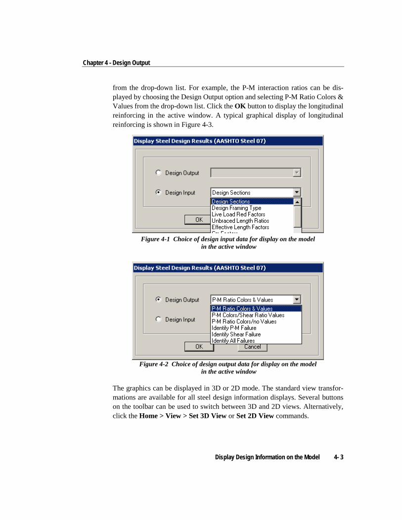
Chapter 4 - Design Output
from the drop-down list. For example, the P-M interaction ratios can be dis-played by choosing the Design Output option and selecting P-M Ratio Colors & Values from the drop-down list. Click the OK button to display the longitudinal reinforcing in the active window. A typical graphical display of longitudinal reinforcing is shown in Figure 4-3.
Figure 4-1 Choice of design input data for display on the model
in the active window
Figure 4-2 Choice of design output data for display on the model
in the active window
The graphics can be displayed in 3D or 2D mode. The standard view transfor-mations are available for all steel design information displays. Several buttons on the toolbar can be used to switch between 3D and 2D views. Alternatively, click the Home > View > Set 3D View or Set 2D View commands.
Display Design Information on the Model 4- 3
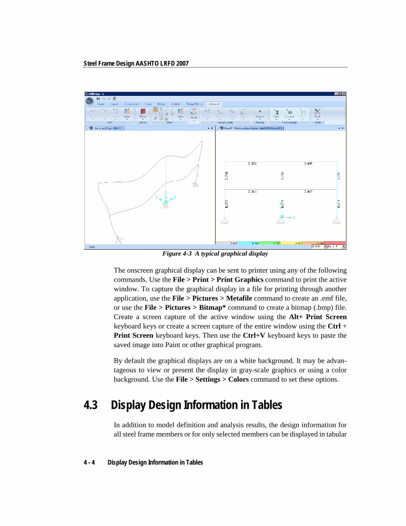
Steel Frame Design AASHTO LRFD 2007
Figure 4-3 A typical graphical display
The onscreen graphical display can be sent to printer using any of the following commands. Use the File > Print > Print Graphics command to print the active window. To capture the graphical display in a file for printing through another application, use the File > Pictures > Metafile command to create an .emf file, or use the File > Pictures > Bitmap* command to create a bitmap (.bmp) file. Create a screen capture of the active window using the Alt+ Print Screen keyboard keys or create a screen capture of the entire window using the Ctrl + Print Screen keyboard keys. Then use the Ctrl+V keyboard keys to paste the saved image into Paint or other graphical program.
By default the graphical displays are on a white background. It may be advan-tageous to view or present the display in gray-scale graphics or using a color background. Use the File > Settings > Colors command to set these options.
4.3 Display Design Information in Tables In addition to model definition and analysis results, the design information for all steel frame members or for only selected members can be displayed in tabular
4 - 4 Display Design Information in Tables
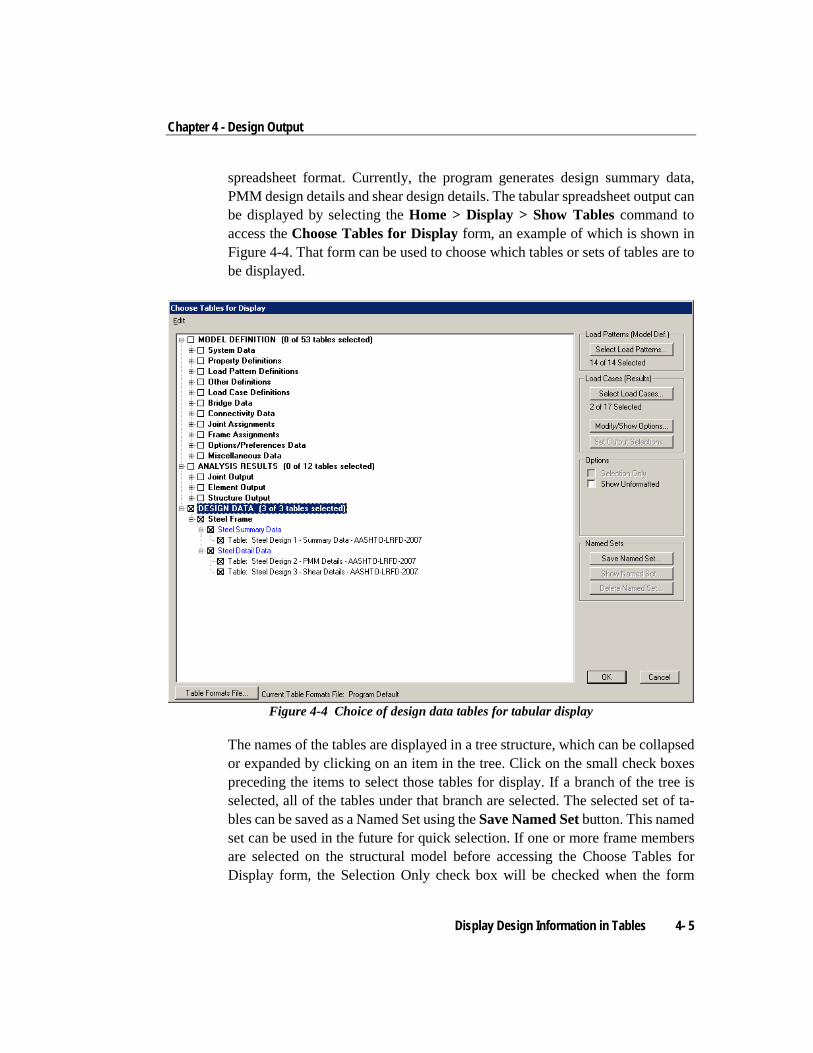
Chapter 4 - Design Output
spreadsheet format. Currently, the program generates design summary data, PMM design details and shear design details. The tabular spreadsheet output can be displayed by selecting the Home > Display > Show Tables command to access the Choose Tables for Display form, an example of which is shown in Figure 4-4. That form can be used to choose which tables or sets of tables are to be displayed.
Figure 4-4 Choice of design data tables for tabular display
The names of the tables are displayed in a tree structure, which can be collapsed or expanded by clicking on an item in the tree. Click on the small check boxes preceding the items to select those tables for display. If a branch of the tree is selected, all of the tables under that branch are selected. The selected set of ta-bles can be saved as a Named Set using the Save Named Set button. This named set can be used in the future for quick selection. If one or more frame members are selected on the structural model before accessing the Choose Tables for Display form, the Selection Only check box will be checked when the form
Display Design Information in Tables 4- 5
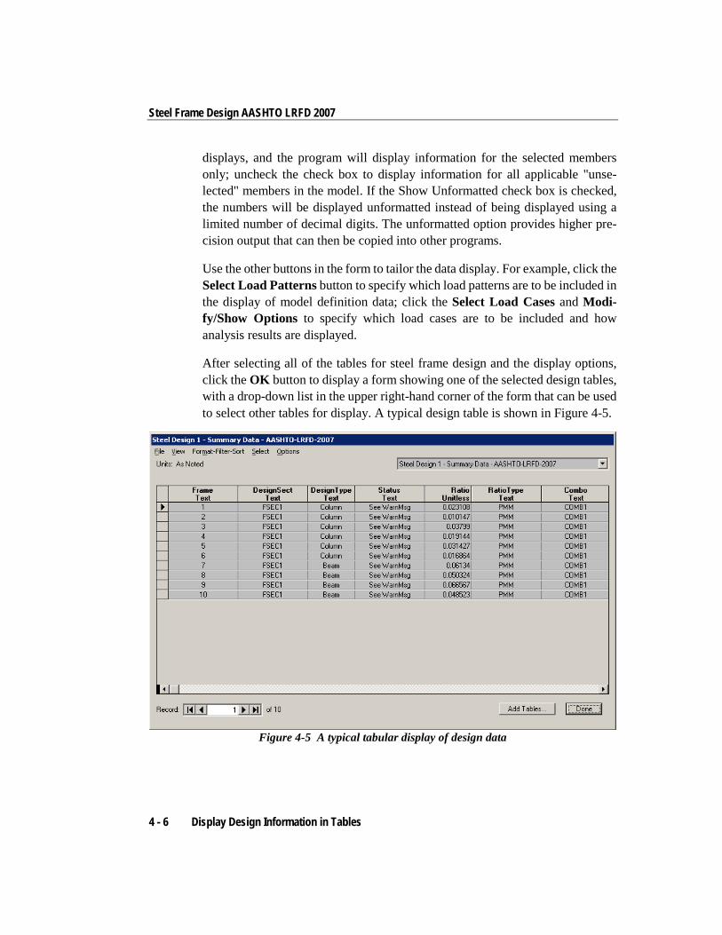
Steel Frame Design AASHTO LRFD 2007
displays, and the program will display information for the selected members only; uncheck the check box to display information for all applicable "unse-lected" members in the model. If the Show Unformatted check box is checked, the numbers will be displayed unformatted instead of being displayed using a limited number of decimal digits. The unformatted option provides higher pre-cision output that can then be copied into other programs.
Use the other buttons in the form to tailor the data display. For example, click the Select Load Patterns button to specify which load patterns are to be included in the display of model definition data; click the Select Load Cases and Modi-fy/Show Options to specify which load cases are to be included and how analysis results are displayed.
After selecting all of the tables for steel frame design and the display options, click the OK button to display a form showing one of the selected design tables, with a drop-down list in the upper right-hand corner of the form that can be used to select other tables for display. A typical design table is shown in Figure 4-5.
Figure 4-5 A typical tabular display of design data
4 - 6 Display Design Information in Tables
Chapter 4 - Design Output
Use the scroll bars on the bottom and right side of the tables to scroll right and left or up and down if portions of the data table can not be displayed in the form's display area. The columns can be resized by clicking the left mouse button on the separator of the headers, holding down the left mouse button and then dragging the mouse to the left or right. Reset the column widths to their default values by selecting the Format-Filter-Sort menu > Reset Default Column Widths command on the form. The table can be split into two or more tables by clicking on the small black rectangular area near the bottom-left corner of the table, holding down the left mouse button, and then dragging the mouse button to the left or right. Repeat this process to add more splits. Use the split and horizontal scroll bar to put two columns side by side for easier comparison. The splits can be removed by selecting the Format-Filter-Sort menu > Remove Splits command on the form. Alternatively, remove the split by clicking, hold-ing and dragging the left mouse button to merge the split key to its original lo-cation.
Select multiple consecutive columns by putting the cursor on the header, holding down the mouse button, and then dragging the mouse button left or right. Al-ternatively, depress the Shift key and click the left mouse button to select a range of columns.
Each of the individual fields (columns) can be formatted. Fields with text in-formation can be set for specific types of alignment (center, left, right) and to specific widths. In addition to setting the alignment and column widths, fields with numeric data can be set for the maximum number of characters, zero tol-erance, number of decimal digits and so forth. The tables can be formatted, fil-tered and sorted using multiple criteria accessed using the Format-Filter-Sort menu on the form. Filtering and sorting features can be useful in identifying critical cases. After specifying the table formatting information, save it to a format file that can be used in the future by selecting the appropriate feature available under the Format-Filter-Sort menu.
The current table (i.e., the table in the active window) can be exported to Excel, Access, .rtf., .html, and plain text formats. In both Excel spreadsheet and Access database formats, the tables can have many columns, making the tables very wide. In .rft and .html formats, the tables are split at convenient points to make a reasonably printable document. In plain text format, the tables can be saved with or without the splits. To export a table to Excel, for example, select the File menu > Export Current Table > To Excel command. The program will export
Display Design Information in Tables 4- 7
Steel Frame Design AASHTO LRFD 2007
the entire table to an Excel spreadsheet workbook and will automatically open the file in MS Excel. Similarly, if the table is exported to other formats, the default editor specific to that format will open the document, provided that the editor is available in the computer. The table will be saved in that format only if the relevant editor is not available. Instead of exporting or displaying the cur-rently displayed table, the entire set of available tables can be exported and displayed in the afore-mentioned formats by selecting the File menu and the appropriate submenu command. With these exporting and display features, the tables can be saved in many required formats and can be printed. Many other features of the design tables are left for the user to discover by using the pro-gram.
4.4 Display Detailed Member Specific Information The program has the capability to display the design details for a specific member. The information includes member identification, shape name, section properties, design combination name, design combination forces, and other de-sign input data to check the design results. The information also includes stress ratios for P-M-M and other interactions, demand/capacity ratios from shear, nominal strengths, design factors such as K, Cm, Cb, δb, δs, and so forth. The design details are displayed in a summary form and also are displayed for a specific load combination and for a specific station of a frame member.
When the design results are displayed on the model in the active window, the detailed design information can be accessed by right clicking on the desired frame member to display the Steel Stress Check Information form. Alterna-tively, click the Advanced > Frame Design > Steel > Interactive Steel Frame Design command and then right click on the frame member. An example of that form is shown in Figure 4-6.
The Steel Stress Check Information form identifies the frame members and the analysis and design section, and includes a display area of mostly de-mand/capacity ratio data and buttons that access forms that provide further de-tails about the selected frame member. The display area reports the load combinations, the stress check stations, the P-M-M interaction ratio along with its axial and flexural components, and the shear stress ratios. The load combi-nation is reported by its name, while the station is reported by its location, which is measured from the I-end of the column. The number of reported line items in
4 - 8 Display Detailed Member Specific Information
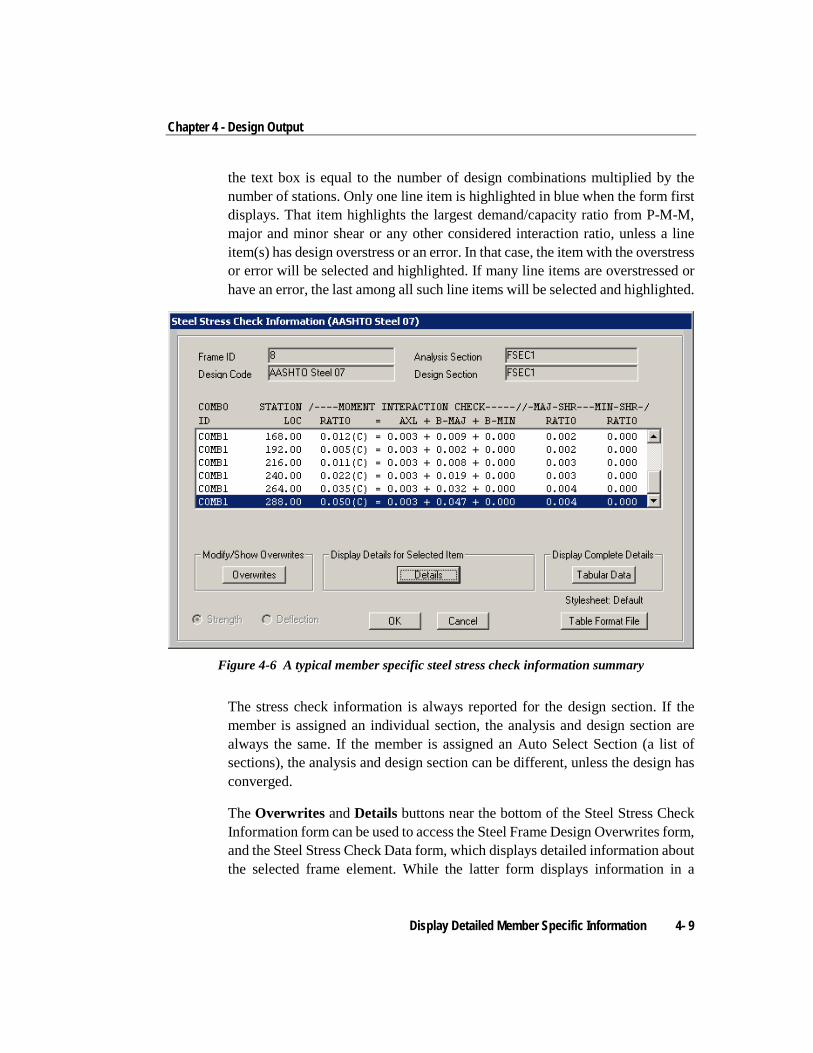
Chapter 4 - Design Output
the text box is equal to the number of design combinations multiplied by the number of stations. Only one line item is highlighted in blue when the form first displays. That item highlights the largest demand/capacity ratio from P-M-M, major and minor shear or any other considered interaction ratio, unless a line item(s) has design overstress or an error. In that case, the item with the overstress or error will be selected and highlighted. If many line items are overstressed or have an error, the last among all such line items will be selected and highlighted.
Figure 4-6 A typical member specific steel stress check information summary
The stress check information is always reported for the design section. If the member is assigned an individual section, the analysis and design section are always the same. If the member is assigned an Auto Select Section (a list of sections), the analysis and design section can be different, unless the design has converged.
The Overwrites and Details buttons near the bottom of the Steel Stress Check Information form can be used to access the Steel Frame Design Overwrites form, and the Steel Stress Check Data form, which displays detailed information about the selected frame element. While the latter form displays information in a
Display Detailed Member Specific Information 4- 9
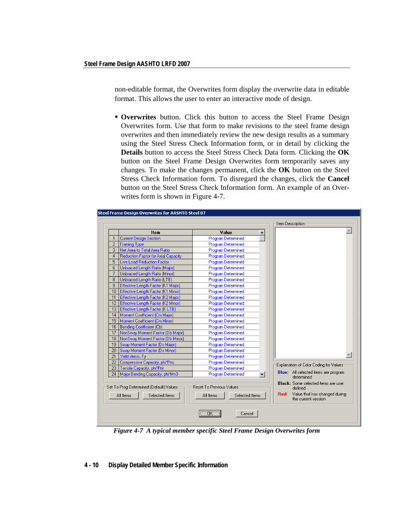
Steel Frame Design AASHTO LRFD 2007
non-editable format, the Overwrites form display the overwrite data in editable format. This allows the user to enter an interactive mode of design.
Overwrites button. Click this button to access the Steel Frame Design Overwrites form. Use that form to make revisions to the steel frame design overwrites and then immediately review the new design results as a summary using the Steel Stress Check Information form, or in detail by clicking the Details button to access the Steel Stress Check Data form. Clicking the OK button on the Steel Frame Design Overwrites form temporarily saves any changes. To make the changes permanent, click the OK button on the Steel Stress Check Information form. To disregard the changes, click the Cancel button on the Steel Stress Check Information form. An example of an Over-writes form is shown in Figure 4-7.
Figure 4-7 A typical member specific Steel Frame Design Overwrites form
4 - 10 Display Detailed Member Specific Information
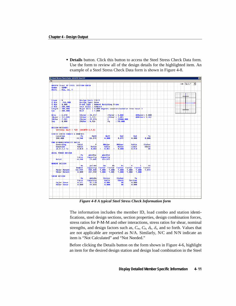
Chapter 4 - Design Output
Details button. Click this button to access the Steel Stress Check Data form. Use the form to review all of the design details for the highlighted item. An example of a Steel Stress Check Data form is shown in Figure 4-8.
Figure 4-8 A typical Steel Stress Check Information form
The information includes the member ID, load combo and station identi-fications, steel design sections, section properties, design combination forces, stress ratios for P-M-M and other interactions, stress ratios for shear, nominal strengths, and design factors such as, Cm, Cb, δb, δs, and so forth. Values that are not applicable are reported as N/A. Similarly, N/C and N/N indicate an item is “Not Calculated” and “Not Needed.”
Before clicking the Details button on the form shown in Figure 4-6, highlight an item for the desired design station and design load combination in the Steel
Display Detailed Member Specific Information 4- 11
Steel Frame Design AASHTO LRFD 2007
Stress Check Information display area by clicking on the line. The data sub-sequently displayed will relate to the highlighted item. By default, the most critical line item is selected when the form first displays, as described previ-ously.
To increase or decrease the width of the Steel Stress Check Information form (Figure 4-8), put the cursor near the right edge of the form, click the left mouse button, and drag the mouse cursor towards the left or right. Similarly, the height of the form can be increased or decreased.
The text in the form can be dragged in any direction by positioning the cursor in the middle of the form, and then clicking the left mouse button and dragging the text in the desired direction. Similarly, the graphical display of the column section can also be dragged in any direction.
Use the Units drop-down list in the upper right-hand corner of the form to change the units used to display the data. Data displayed on the form can be sent directly to the printer by selecting the File menu > Print command on the form. The program allows limited page setup options using the Print Setup command on the File menu on the form.
The Steel Stress Check Information form also includes a Tabular Data button that when clicked displays member specific design details in a spreadsheet type format. The tabular display of design information has been described in the previous section. In that case, the information displayed is specific to the selected member only. The tabular output is shown for all stations and all de-sign load combinations for the selected member. An example of design details table that displays after clicking the Tabular Data button is shown in Figure 4-9.
4 - 12 Display Detailed Member Specific Information
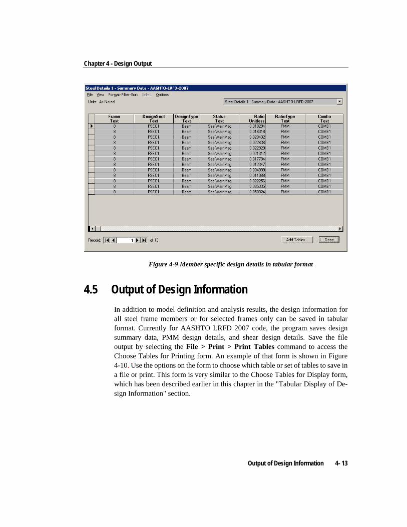
Chapter 4 - Design Output
Figure 4-9 Member specific design details in tabular format
4.5 Output of Design Information In addition to model definition and analysis results, the design information for all steel frame members or for selected frames only can be saved in tabular format. Currently for AASHTO LRFD 2007 code, the program saves design summary data, PMM design details, and shear design details. Save the file output by selecting the File > Print > Print Tables command to access the Choose Tables for Printing form. An example of that form is shown in Figure 4-10. Use the options on the form to choose which table or set of tables to save in a file or print. This form is very similar to the Choose Tables for Display form, which has been described earlier in this chapter in the "Tabular Display of De-sign Information" section.
Output of Design Information 4- 13
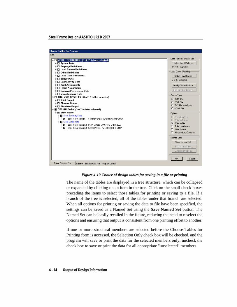
Steel Frame Design AASHTO LRFD 2007
Figure 4-10 Choice of design tables for saving in a file or printing
The name of the tables are displayed in a tree structure, which can be collapsed or expanded by clicking on an item in the tree. Click on the small check boxes preceding the items to select those tables for printing or saving to a file. If a branch of the tree is selected, all of the tables under that branch are selected. When all options for printing or saving the data to file have been specified, the settings can be saved as a Named Set using the Save Named Set button. The Named Set can be easily recalled in the future, reducing the need to reselect the options and ensuring that output is consistent from one printing effort to another.
If one or more structural members are selected before the Choose Tables for Printing form is accessed, the Selection Only check box will be checked, and the program will save or print the data for the selected members only; uncheck the check box to save or print the data for all appropriate "unselected" members.
4 - 14 Output of Design Information
Chapter 4 - Design Output
The output can be generated in a variety of formats, including rich text format (.rft), plain text with and without splits or page breaks (.txt), and hyperlink text markup language (.htm) by choosing the appropriate option on the right side of the form.
Printed output can be specified to have a landscaped orientation, in which the width of the resulting printout on a given page is longer than the height of the printout.
Filtering criteria can be applied if those criteria were specified using the For-mat-Filter-Sort menu > Format Table command when the selected data tables were displayed using the Display menu > Show Tables command. The output also can be specified to include a hyperlinked contents to facilitate accessing specific areas of the printout.
There are other buttons on the form that do not affect saving or printing design information. For example, the Select Load Patterns button affects only sav-ing/printing model definition data. The Select Load Cases and Modify/Show Options buttons affect only saving/printing analysis results.
After clicking all the necessary tables for steel frame design and all necessary options, clicking the OK button will save/print the design tables.
4.6 Error Messages and Warnings Error messages and warnings may be displayed in the steel frame design output. Those messages and warnings are assumed to be self explanatory.
Error Messages and Warnings 4- 15
Appendix A Steel Frame Design Preferences
The Steel Frame Design Preferences are basic assignments that apply to all of the steel frame members. Tables A-1, A-2, and A-3 list Steel Frame Design Preferences for "AASHTO 2007" Default values are provided for all preference items. Thus, it is not necessary to specify or change any of the preferences. However, at least review the default values to ensure they are acceptable. Some of the preference items also are available as member specific overwrite items. The Overwrites are described in Appendix D. Overwritten values take prece-dence over the preferences.
To view design preferences, select the Options menu > Preferences > Steel Frame Design command. The Preferences form will display. The preference options are displayed in a two-column spreadsheet on that form. The left column of the spreadsheet displays the Preference item name. The right column of the spreadsheet displays the preference item value.
To change a preference item, left click the desired Preference item in the left or right column of the spreadsheet. This activates a drop-down list or highlights the current preference value. If the drop-down list displays, select a new value. If the cell is highlighted, type in the desired value. The preference value will update accordingly. Values in the drop-down lists provide the available options.
Appendix A - 1
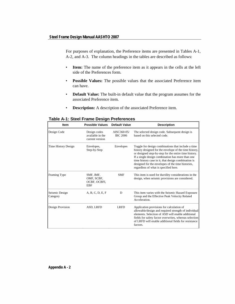
Steel Frame Design Manual AASHTO 2007
For purposes of explanation, the Preference items are presented in Tables A-1, A-2, and A-3. The column headings in the tables are described as follows:
• Item: The name of the preference item as it appears in the cells at the left side of the Preferences form.
• Possible Values: The possible values that the associated Preference item can have.
• Default Value: The built-in default value that the program assumes for the associated Preference item.
• Description: A description of the associated Preference item.
Table A-1: Steel Frame Design Preferences Item Possible Values Default Value Description
Design Code Design codes available in the current version
AISC360-05/ IBC 2006
The selected design code. Subsequent design is based on this selected code.
Time History Design Envelopes, Step-by-Step
Envelopes Toggle for design combinations that include a time history designed for the envelope of the time history, or designed step-by-step for the entire time history. If a single design combination has more than one time history case in it, that design combination is designed for the envelopes of the time histories, regardless of what is specified here.
Framing Type SMF, IMF, OMF, SCBF, OCBF, OCBFI, EBF
SMF This item is used for ductility considerations in the design, when seismic provisions are considered.
Seismic Design Category
A, B, C, D, E, F D This item varies with the Seismic Hazard Exposure Group and the Effective Peak Velocity Related Acceleration.
Design Provision ASD, LRFD LRFD Application provisions for calculation of allowable/design and required strength of individual elements. Selection of ASD will enable additional fields for safety factor overwrites, whereas selection of LRFD will enable additional fields for resistance factors.
Appendix A - 2
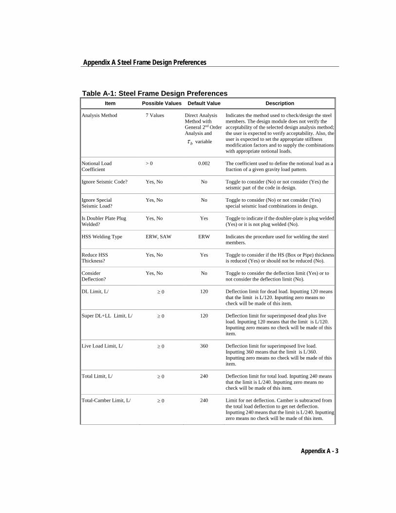
Appendix A Steel Frame Design Preferences
Table A-1: Steel Frame Design Preferences Item Possible Values Default Value Description
Analysis Method 7 Values Direct Analysis Method with General 2nd Order Analysis and bτ variable
Indicates the method used to check/design the steel members. The design module does not verify the acceptability of the selected design analysis method; the user is expected to verify acceptability. Also, the user is expected to set the appropriate stiffness modification factors and to supply the combinations with appropriate notional loads.
Notional Load Coefficient
> 0 0.002 The coefficient used to define the notional load as a fraction of a given gravity load pattern.
Ignore Seismic Code? Yes, No No Toggle to consider (No) or not consider (Yes) the seismic part of the code in design.
Ignore Special Seismic Load?
Yes, No No Toggle to consider (No) or not consider (Yes) special seismic load combinations in design.
Is Doubler Plate Plug Welded?
Yes, No Yes Toggle to indicate if the doubler-plate is plug welded (Yes) or it is not plug welded (No).
HSS Welding Type ERW, SAW ERW Indicates the procedure used for welding the steel members.
Reduce HSS Thickness?
Yes, No Yes Toggle to consider if the HS (Box or Pipe) thickness is reduced (Yes) or should not be reduced (No).
Consider Deflection?
Yes, No No Toggle to consider the deflection limit (Yes) or to not consider the deflection limit (No).
DL Limit, L/ ≥ 0 120 Deflection limit for dead load. Inputting 120 means that the limit is L/120. Inputting zero means no check will be made of this item.
Super DL+LL Limit, L/ ≥ 0 120 Deflection limit for superimposed dead plus live load. Inputting 120 means that the limit is L/120. Inputting zero means no check will be made of this item.
Live Load Limit, L/ ≥ 0 360 Deflection limit for superimposed live load. Inputting 360 means that the limit is L/360. Inputting zero means no check will be made of this item.
Total Limit, L/ ≥ 0 240 Deflection limit for total load. Inputting 240 means that the limit is L/240. Inputting zero means no check will be made of this item.
Total-Camber Limit, L/ ≥ 0 240 Limit for net deflection. Camber is subtracted from the total load deflection to get net deflection. Inputting 240 means that the limit is L/240. Inputting zero means no check will be made of this item.
Appendix A - 3
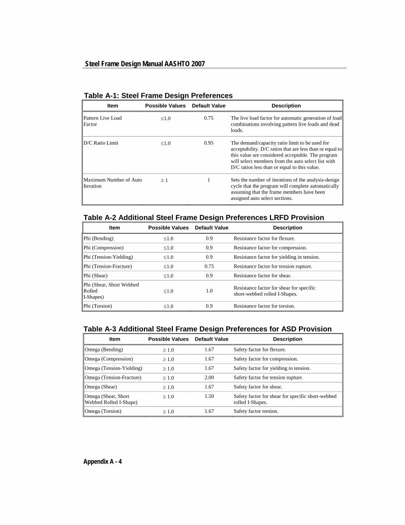
Steel Frame Design Manual AASHTO 2007
Table A-1: Steel Frame Design Preferences Item Possible Values Default Value Description
Pattern Live Load Factor
≤1.0 0.75 The live load factor for automatic generation of load combinations involving pattern live loads and dead loads.
D/C Ratio Limit ≤1.0 0.95 The demand/capacity ratio limit to be used for acceptability. D/C ratios that are less than or equal to this value are considered acceptable. The program will select members from the auto select list with D/C ratios less than or equal to this value.
Maximum Number of Auto Iteration
≥ 1 1 Sets the number of iterations of the analysis-design cycle that the program will complete automatically assuming that the frame members have been assigned auto select sections.
Table A-2 Additional Steel Frame Design Preferences LRFD Provision Item Possible Values Default Value Description
Phi (Bending) ≤1.0 0.9 Resistance factor for flexure.
Phi (Compression) ≤1.0 0.9 Resistance factor for compression.
Phi (Tension-Yielding) ≤1.0 0.9 Resistance factor for yielding in tension.
Phi (Tension-Fracture) ≤1.0 0.75 Resistance factor for tension rupture.
Phi (Shear) ≤1.0 0.9 Resistance factor for shear.
Phi (Shear, Short Webbed Rolled I-Shapes)
≤1.0 1.0 Resistance factor for shear for specific short-webbed rolled I-Shapes.
Phi (Torsion) ≤1.0 0.9 Resistance factor for torsion.
Table A-3 Additional Steel Frame Design Preferences for ASD Provision
Item Possible Values Default Value Description
Omega (Bending) ≥ 1.0 1.67 Safety factor for flexure.
Omega (Compression) ≥ 1.0 1.67 Safety factor for compression.
Omega (Tension-Yielding) ≥ 1.0 1.67 Safety factor for yielding in tension.
Omega (Tension-Fracture) ≥ 1.0 2.00 Safety factor for tension rupture.
Omega (Shear) ≥ 1.0 1.67 Safety factor for shear.
Omega (Shear, Short Webbed Rolled I-Shape)
≥ 1.0 1.50 Safety factor for shear for specific short-webbed rolled I-Shapes.
Omega (Torsion) ≥ 1.0 1.67 Safety factor torsion.
Appendix A - 4
Appendix B Frame Design Procedure Overwrites
The structural model may contain frame elements made of several structural materials: steel, concrete, aluminum, cold-formed steel and other materials. The program supports separate design procedures for each material type. By default the program determines the design procedure from the material of the frame member.
SAP2000 allows the user to turn off or turn on design of specific members by selecting No Design or Default from material. Overwriting the design procedure can be accessed from the Design menu > Overwrite Frame Design Procedure command.
ETABS supports both regular steel frame design and composite beam design. The determination of design procedure is different. If the material is concrete, the design procedure is concrete. If the material is steel, the default design procedure can be steel frame design or composite beam design. If the section is of steel material, and the member satisfies a host of other criteria, such as the member is horizontal (beam), it supports a filled deck or slab, it is an I-shaped member, it is hinged at both ends and so on, then the default design procedure is taken as composite beam design; otherwise, the default design procedure is taken as steel frame design. ETABS allows the user to overwrite a steel member frame design procedure to steel frame design, composite beam design, default, or no design. Change the design procedure by selecting the member(s)
Appendix B - 1
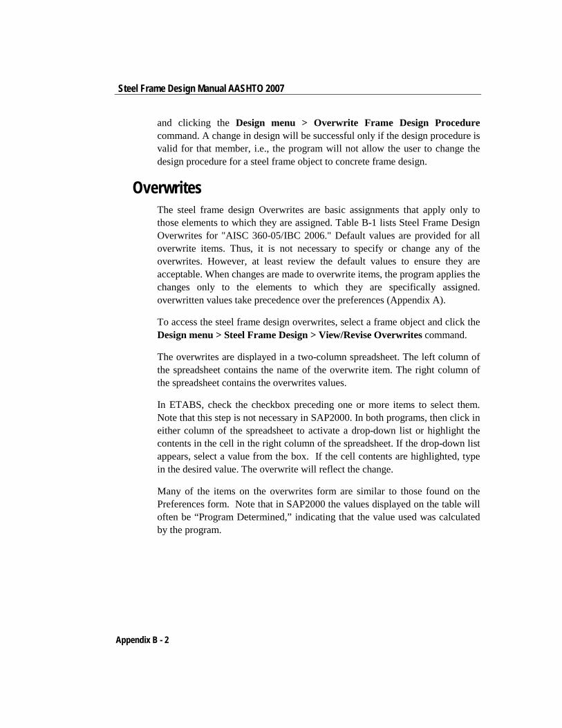
Steel Frame Design Manual AASHTO 2007
and clicking the Design menu > Overwrite Frame Design Procedure command. A change in design will be successful only if the design procedure is valid for that member, i.e., the program will not allow the user to change the design procedure for a steel frame object to concrete frame design.
Overwrites The steel frame design Overwrites are basic assignments that apply only to those elements to which they are assigned. Table B-1 lists Steel Frame Design Overwrites for "AISC 360-05/IBC 2006." Default values are provided for all overwrite items. Thus, it is not necessary to specify or change any of the overwrites. However, at least review the default values to ensure they are acceptable. When changes are made to overwrite items, the program applies the changes only to the elements to which they are specifically assigned. overwritten values take precedence over the preferences (Appendix A).
To access the steel frame design overwrites, select a frame object and click the Design menu > Steel Frame Design > View/Revise Overwrites command.
The overwrites are displayed in a two-column spreadsheet. The left column of the spreadsheet contains the name of the overwrite item. The right column of the spreadsheet contains the overwrites values.
In ETABS, check the checkbox preceding one or more items to select them. Note that this step is not necessary in SAP2000. In both programs, then click in either column of the spreadsheet to activate a drop-down list or highlight the contents in the cell in the right column of the spreadsheet. If the drop-down list appears, select a value from the box. If the cell contents are highlighted, type in the desired value. The overwrite will reflect the change.
Many of the items on the overwrites form are similar to those found on the Preferences form. Note that in SAP2000 the values displayed on the table will often be “Program Determined,” indicating that the value used was calculated by the program.
Appendix B - 2
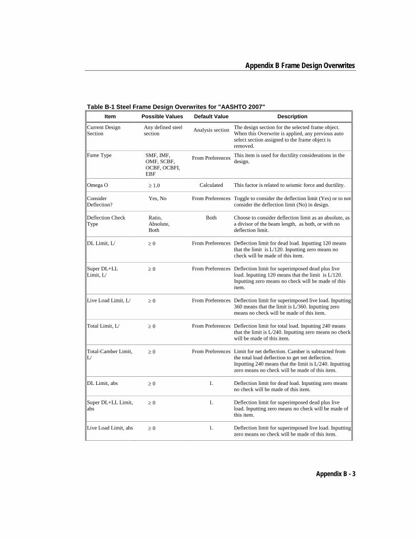
Appendix B Frame Design Overwrites
Table B-1 Steel Frame Design Overwrites for "AASHTO 2007" Item Possible Values Default Value Description
Current Design Section
Any defined steel section Analysis section The design section for the selected frame object.
When this Overwrite is applied, any previous auto select section assigned to the frame object is removed.
Fame Type SMF, IMF, OMF, SCBF, OCBF, OCBFI, EBF
From Preferences This item is used for ductility considerations in the design.
Omega O ≥ 1.0 Calculated This factor is related to seismic force and ductility.
Consider Deflection?
Yes, No From Preferences Toggle to consider the deflection limit (Yes) or to not consider the deflection limit (No) in design.
Deflection Check Type
Ratio, Absolute, Both
Both Choose to consider deflection limit as an absolute, as a divisor of the beam length, as both, or with no deflection limit.
DL Limit, L/ ≥ 0 From Preferences Deflection limit for dead load. Inputting 120 means that the limit is L/120. Inputting zero means no check will be made of this item.
Super DL+LL Limit, L/
≥ 0 From Preferences Deflection limit for superimposed dead plus live load. Inputting 120 means that the limit is L/120. Inputting zero means no check will be made of this item.
Live Load Limit, L/ ≥ 0 From Preferences Deflection limit for superimposed live load. Inputting 360 means that the limit is L/360. Inputting zero means no check will be made of this item.
Total Limit, L/ ≥ 0 From Preferences Deflection limit for total load. Inputting 240 means that the limit is L/240. Inputting zero means no check will be made of this item.
Total-Camber Limit, L/
≥ 0 From Preferences Limit for net deflection. Camber is subtracted from the total load deflection to get net deflection. Inputting 240 means that the limit is L/240. Inputting zero means no check will be made of this item.
DL Limit, abs ≥ 0 1. Deflection limit for dead load. Inputting zero means no check will be made of this item.
Super DL+LL Limit, abs
≥ 0 1. Deflection limit for superimposed dead plus live load. Inputting zero means no check will be made of this item.
Live Load Limit, abs ≥ 0 1. Deflection limit for superimposed live load. Inputting zero means no check will be made of this item.
Appendix B - 3
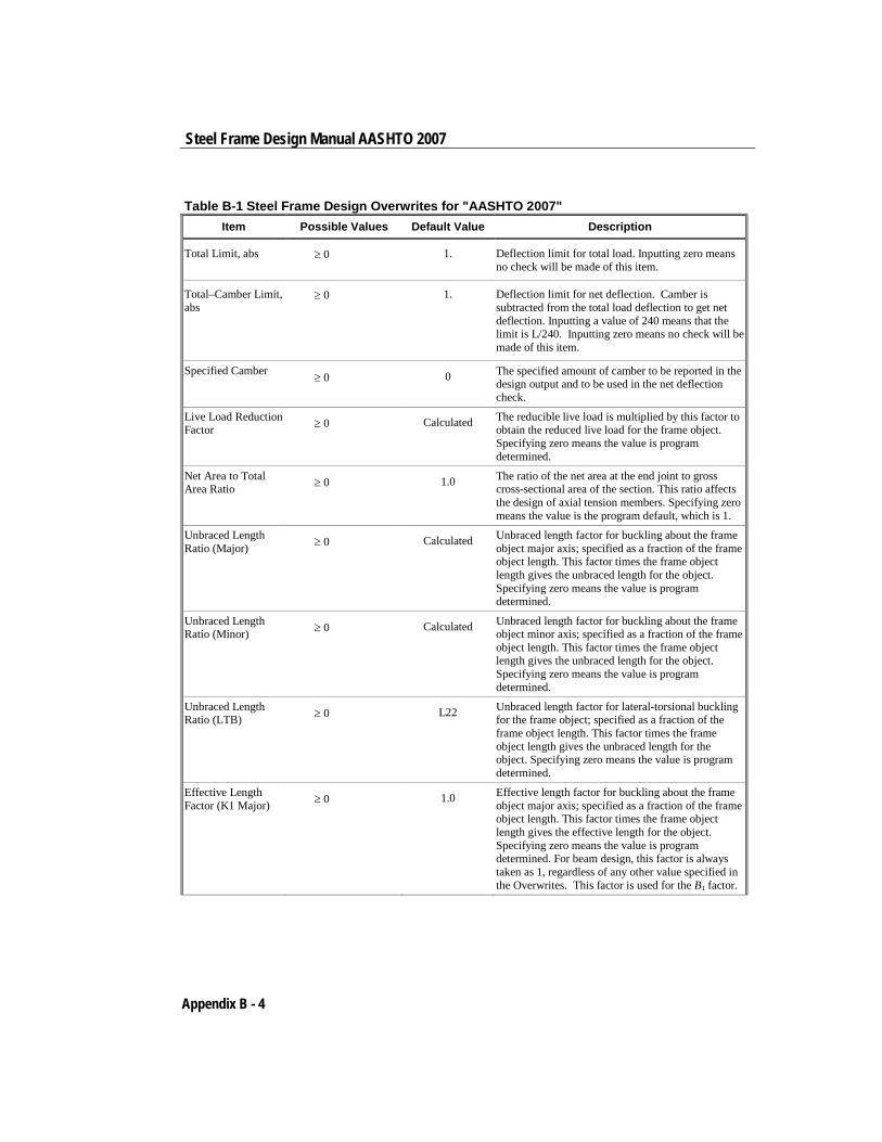
Steel Frame Design Manual AASHTO 2007
Table B-1 Steel Frame Design Overwrites for "AASHTO 2007" Item Possible Values Default Value Description
Total Limit, abs ≥ 0 1. Deflection limit for total load. Inputting zero means no check will be made of this item.
Total–Camber Limit, abs
≥ 0 1. Deflection limit for net deflection. Camber is subtracted from the total load deflection to get net deflection. Inputting a value of 240 means that the limit is L/240. Inputting zero means no check will be made of this item.
Specified Camber ≥ 0 0 The specified amount of camber to be reported in the design output and to be used in the net deflection check.
Live Load Reduction Factor ≥ 0 Calculated The reducible live load is multiplied by this factor to
obtain the reduced live load for the frame object. Specifying zero means the value is program determined.
Net Area to Total Area Ratio ≥ 0 1.0 The ratio of the net area at the end joint to gross
cross-sectional area of the section. This ratio affects the design of axial tension members. Specifying zero means the value is the program default, which is 1.
Unbraced Length Ratio (Major) ≥ 0 Calculated Unbraced length factor for buckling about the frame
object major axis; specified as a fraction of the frame object length. This factor times the frame object length gives the unbraced length for the object. Specifying zero means the value is program determined.
Unbraced Length Ratio (Minor) ≥ 0 Calculated Unbraced length factor for buckling about the frame
object minor axis; specified as a fraction of the frame object length. This factor times the frame object length gives the unbraced length for the object. Specifying zero means the value is program determined.
Unbraced Length Ratio (LTB) ≥ 0 L22 Unbraced length factor for lateral-torsional buckling
for the frame object; specified as a fraction of the frame object length. This factor times the frame object length gives the unbraced length for the object. Specifying zero means the value is program determined.
Effective Length Factor (K1 Major) ≥ 0 1.0 Effective length factor for buckling about the frame
object major axis; specified as a fraction of the frame object length. This factor times the frame object length gives the effective length for the object. Specifying zero means the value is program determined. For beam design, this factor is always taken as 1, regardless of any other value specified in the Overwrites. This factor is used for the B1 factor.
Appendix B - 4
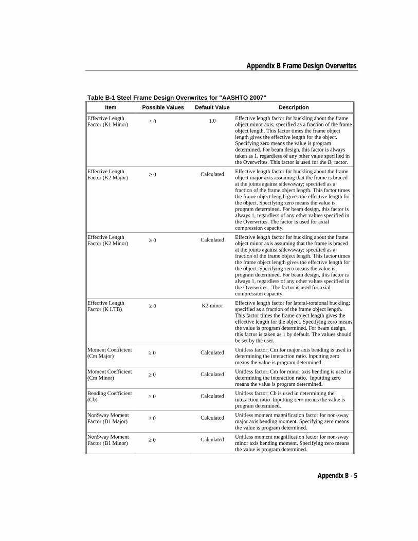
Appendix B Frame Design Overwrites
Table B-1 Steel Frame Design Overwrites for "AASHTO 2007" Item Possible Values Default Value Description
Effective Length Factor (K1 Minor) ≥ 0 1.0 Effective length factor for buckling about the frame
object minor axis; specified as a fraction of the frame object length. This factor times the frame object length gives the effective length for the object. Specifying zero means the value is program determined. For beam design, this factor is always taken as 1, regardless of any other value specified in the Overwrites. This factor is used for the B1 factor.
Effective Length Factor (K2 Major) ≥ 0 Calculated Effective length factor for buckling about the frame
object major axis assuming that the frame is braced at the joints against sidewsway; specified as a fraction of the frame object length. This factor times the frame object length gives the effective length for the object. Specifying zero means the value is program determined. For beam design, this factor is always 1, regardless of any other values specified in the Overwrites. The factor is used for axial compression capacity.
Effective Length Factor (K2 Minor) ≥ 0 Calculated Effective length factor for buckling about the frame
object minor axis assuming that the frame is braced at the joints against sidewsway; specified as a fraction of the frame object length. This factor times the frame object length gives the effective length for the object. Specifying zero means the value is program determined. For beam design, this factor is always 1, regardless of any other values specified in the Overwrites. The factor is used for axial compression capacity.
Effective Length Factor (K LTB) ≥ 0 K2 minor Effective length factor for lateral-torsional buckling;
specified as a fraction of the frame object length. This factor times the frame object length gives the effective length for the object. Specifying zero means the value is program determined. For beam design, this factor is taken as 1 by default. The values should be set by the user.
Moment Coefficient (Cm Major) ≥ 0 Calculated Unitless factor; Cm for major axis bending is used in
determining the interaction ratio. Inputting zero means the value is program determined.
Moment Coefficient (Cm Minor) ≥ 0 Calculated Unitless factor; Cm for minor axis bending is used in
determining the interaction ratio. Inputting zero means the value is program determined.
Bending Coefficient (Cb) ≥ 0 Calculated Unitless factor; Cb is used in determining the
interaction ratio. Inputting zero means the value is program determined.
NonSway Moment Factor (B1 Major) ≥ 0 Calculated Unitless moment magnification factor for non-sway
major axis bending moment. Specifying zero means the value is program determined.
NonSway Moment Factor (B1 Minor) ≥ 0 Calculated Unitless moment magnification factor for non-sway
minor axis bending moment. Specifying zero means the value is program determined.
Appendix B - 5
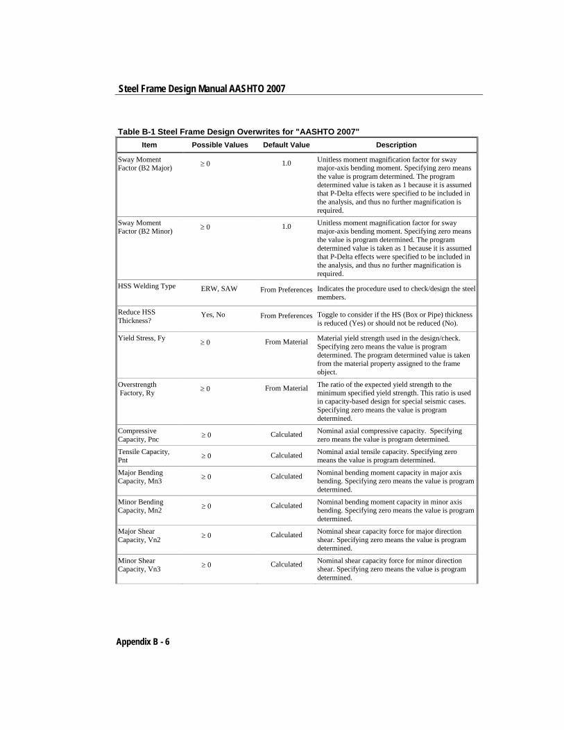
Steel Frame Design Manual AASHTO 2007
Table B-1 Steel Frame Design Overwrites for "AASHTO 2007" Item Possible Values Default Value Description
Sway Moment Factor (B2 Major) ≥ 0 1.0 Unitless moment magnification factor for sway
major-axis bending moment. Specifying zero means the value is program determined. The program determined value is taken as 1 because it is assumed that P-Delta effects were specified to be included in the analysis, and thus no further magnification is required.
Sway Moment Factor (B2 Minor) ≥ 0 1.0 Unitless moment magnification factor for sway
major-axis bending moment. Specifying zero means the value is program determined. The program determined value is taken as 1 because it is assumed that P-Delta effects were specified to be included in the analysis, and thus no further magnification is required.
HSS Welding Type ERW, SAW From Preferences Indicates the procedure used to check/design the steel members.
Reduce HSS Thickness?
Yes, No From Preferences Toggle to consider if the HS (Box or Pipe) thickness is reduced (Yes) or should not be reduced (No).
Yield Stress, Fy ≥ 0 From Material Material yield strength used in the design/check. Specifying zero means the value is program determined. The program determined value is taken from the material property assigned to the frame object.
Overstrength Factory, Ry ≥ 0 From Material The ratio of the expected yield strength to the
minimum specified yield strength. This ratio is used in capacity-based design for special seismic cases. Specifying zero means the value is program determined.
Compressive Capacity, Pnc ≥ 0 Calculated Nominal axial compressive capacity. Specifying
zero means the value is program determined.
Tensile Capacity, Pnt ≥ 0 Calculated Nominal axial tensile capacity. Specifying zero
means the value is program determined.
Major Bending Capacity, Mn3 ≥ 0 Calculated Nominal bending moment capacity in major axis
bending. Specifying zero means the value is program determined.
Minor Bending Capacity, Mn2 ≥ 0 Calculated Nominal bending moment capacity in minor axis
bending. Specifying zero means the value is program determined.
Major Shear Capacity, Vn2 ≥ 0 Calculated Nominal shear capacity force for major direction
shear. Specifying zero means the value is program determined.
Minor Shear Capacity, Vn3 ≥ 0 Calculated Nominal shear capacity force for minor direction
shear. Specifying zero means the value is program determined.
Appendix B - 6
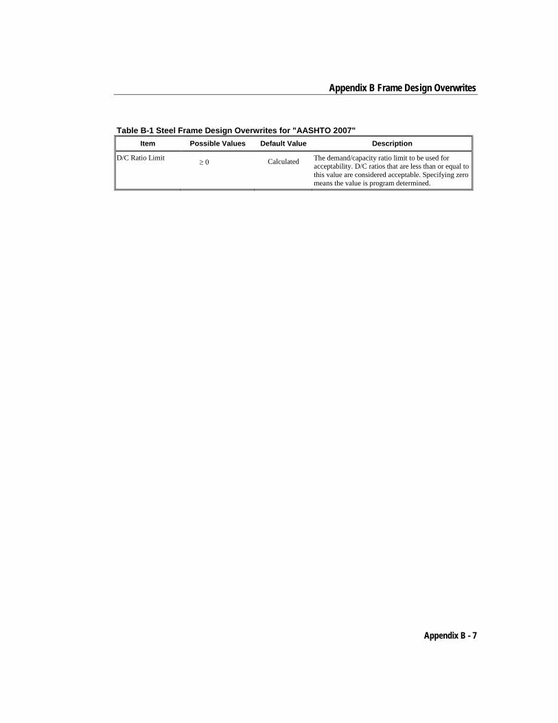
Appendix B Frame Design Overwrites
Table B-1 Steel Frame Design Overwrites for "AASHTO 2007" Item Possible Values Default Value Description
D/C Ratio Limit ≥ 0 Calculated The demand/capacity ratio limit to be used for acceptability. D/C ratios that are less than or equal to this value are considered acceptable. Specifying zero means the value is program determined.
Appendix B - 7
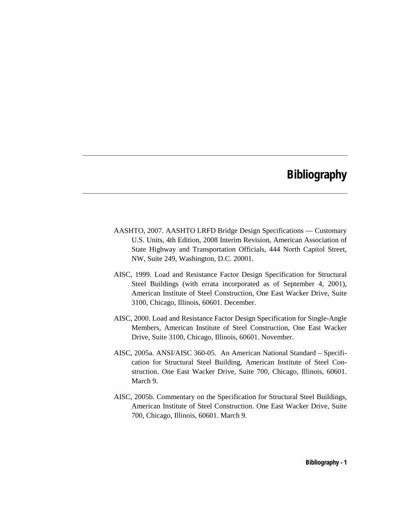
Bibliography
AASHTO, 2007. AASHTO LRFD Bridge Design Specifications — Customary U.S. Units, 4th Edition, 2008 Interim Revision, American Association of State Highway and Transportation Officials, 444 North Capitol Street, NW, Suite 249, Washington, D.C. 20001.
AISC, 1999. Load and Resistance Factor Design Specification for Structural Steel Buildings (with errata incorporated as of September 4, 2001), American Institute of Steel Construction, One East Wacker Drive, Suite 3100, Chicago, Illinois, 60601. December.
AISC, 2000. Load and Resistance Factor Design Specification for Single-Angle Members, American Institute of Steel Construction, One East Wacker Drive, Suite 3100, Chicago, Illinois, 60601. November.
AISC, 2005a. ANSI/AISC 360-05. An American National Standard – Specifi-cation for Structural Steel Building, American Institute of Steel Con-struction. One East Wacker Drive, Suite 700, Chicago, Illinois, 60601. March 9.
AISC, 2005b. Commentary on the Specification for Structural Steel Buildings, American Institute of Steel Construction. One East Wacker Drive, Suite 700, Chicago, Illinois, 60601. March 9.
Bibliography - 1
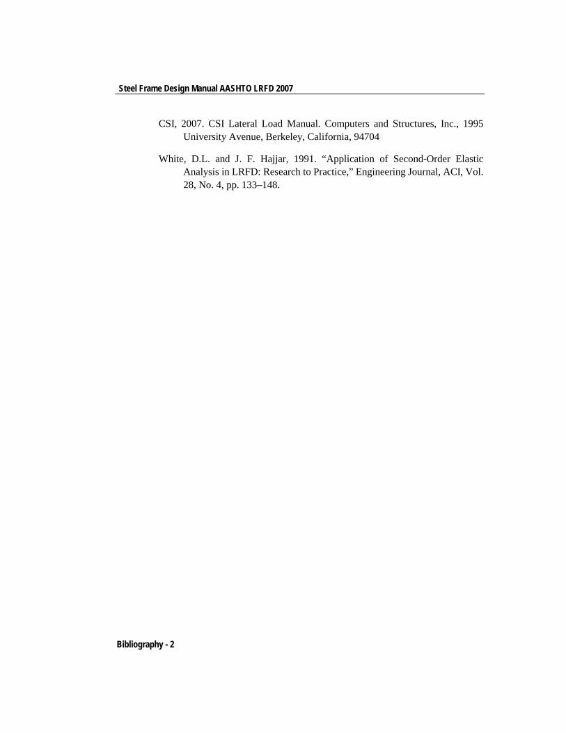
Steel Frame Design Manual AASHTO LRFD 2007
CSI, 2007. CSI Lateral Load Manual. Computers and Structures, Inc., 1995 University Avenue, Berkeley, California, 94704
White, D.L. and J. F. Hajjar, 1991. “Application of Second-Order Elastic Analysis in LRFD: Research to Practice,” Engineering Journal, ACI, Vol. 28, No. 4, pp. 133–148.
Bibliography - 2