Embed Size (px)
Citation preview

Structural option for the Jinping neutrino central detector
Contributor : Yuanqing Wang, Zongyi Wang
Speaker : Zongyi Wang
Department of civil engineering, Tsinghua University
2015-06-05
1
Outline
1. Introduction of the whole structure
2. Bearing capacity of the local joint
3. Introduction of the 1 t scale model
2
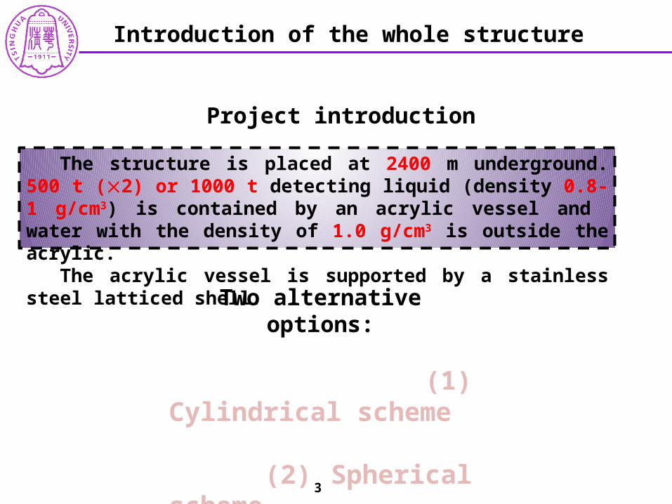
Two alternative options:
(1) Cylindrical scheme
(2) Spherical scheme
The structure is placed at 2400 m underground. 500 t (2) or 1000 t detecting liquid (density 0.8-1 g/cm3) is contained by an acrylic vessel and water with the density of 1.0 g/cm3 is outside the acrylic.
The acrylic vessel is supported by a stainless steel latticed shell.
Project introduction
Introduction of the whole structure
3

Include PMT No PMT
Cylindrical scheme (study in progress)
Diameter of acrylic vessel 11 m , height 11 m Diameter of latticed shell 16 m , height 16 m Fiducial capacity of the vessel 572 t
Introduction of the whole structure
11 m
16 m
4
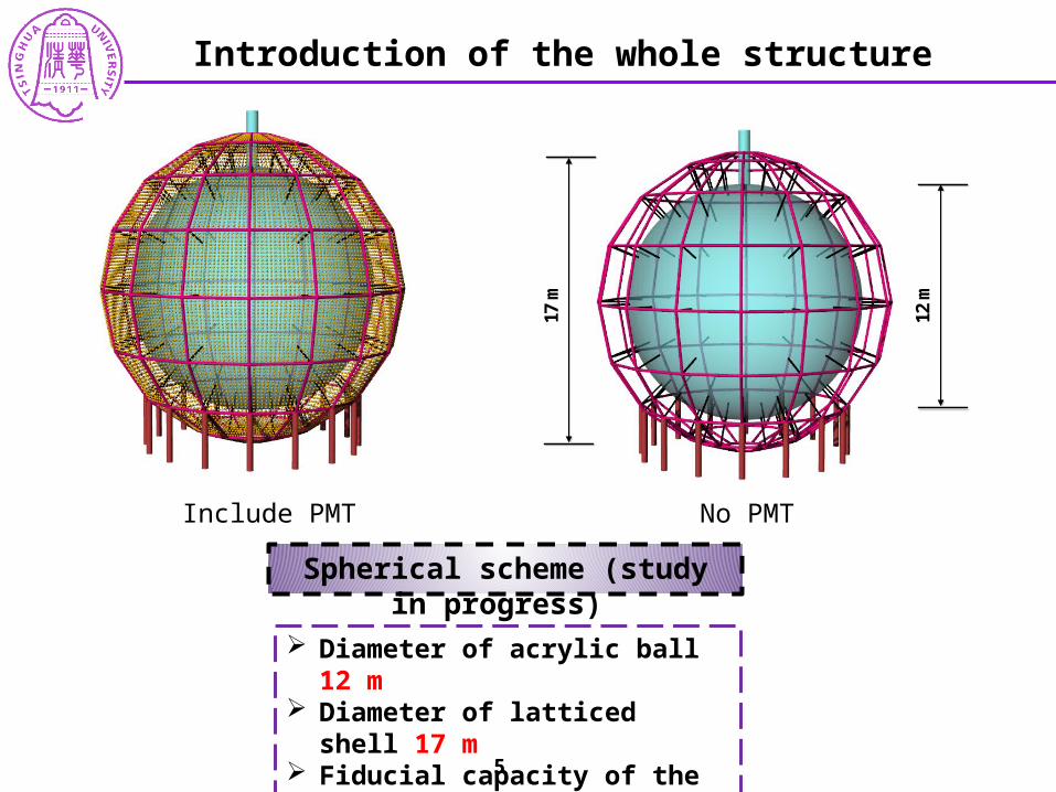
Spherical scheme (study in progress)
Diameter of acrylic ball 12 m Diameter of latticed shell 17 m Fiducial capacity of the vessel 523 t
Introduction of the whole structure
Include PMT No PMT
12 m
17 m
5
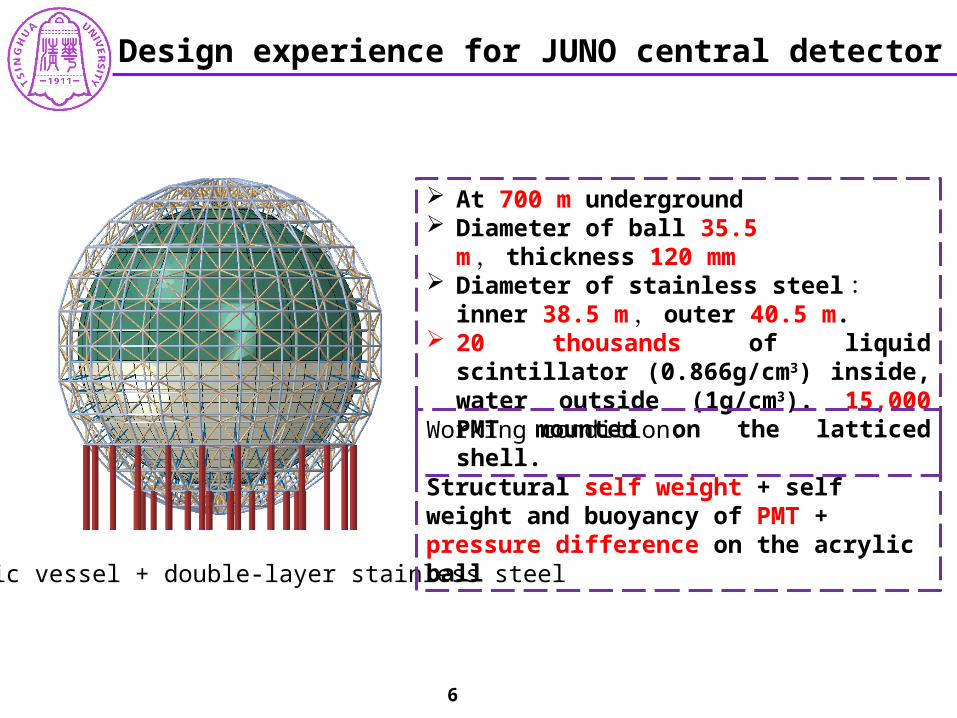
Acrylic vessel + double-layer stainless steel
At 700 m underground Diameter of ball 35.5 m , thickness 120 mm Diameter of stainless steel : inner 38.5
m , outer 40.5 m. 20 thousands of liquid scintillator (0.866g/cm3)
inside, water outside (1g/cm3). 15,000 PMT mounted on the latticed shell.
Working condition:
Structural self weight + self weight and buoyancy of PMT + pressure difference on the acrylic ball
Design experience for JUNO central detector
6
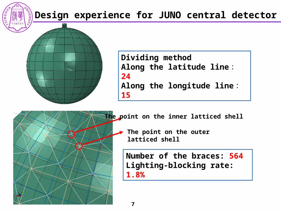
The point on the inner latticed shell
The point on the outer latticed shell
Number of the braces: 564Lighting-blocking rate: 1.8%
Dividing methodAlong the latitude line : 24Along the longitude line : 15
7
Design experience for JUNO central detector
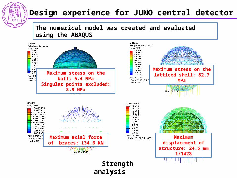
The numerical model was created and evaluated using the ABAQUS
Maximum stress on the ball: 5.4 MPaSingular points excluded: 3.9 MPa
Maximum stress on the latticed shell: 82.7 MPa
Maximum axial force of braces: 134.6 KN
Maximum displacement of structure: 24.5 mm
1/1428
Strength analysis 8
Design experience for JUNO central detector
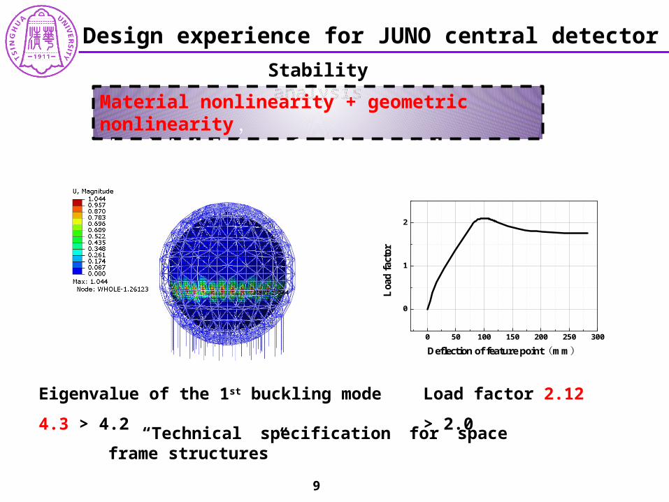
Stability analysis
Load factor 2.12 > 2.0Eigenvalue of the 1st buckling mode 4.3 > 4.2
Material nonlinearity + geometric nonlinearity ,the initial imperfection is taken as 1/300 of the span.
“Technical specification for space frame structures”
0 50 100 150 200 250 300
0
1
2
Loa
d f
acto
r
Deflection of feature point mm( )
9
Design experience for JUNO central detector
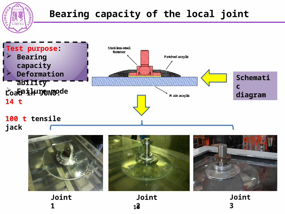
Schematic diagram
Joint 1
Patched acrylic
Stainless-steel fastener
Main acrylic
Joint 2 Joint 3
Bearing capacity of the local joint
Test purpose: Bearing capacity Deformation ability Failure mode
Load in JUNO: 14 t
100 t tensile jack
10
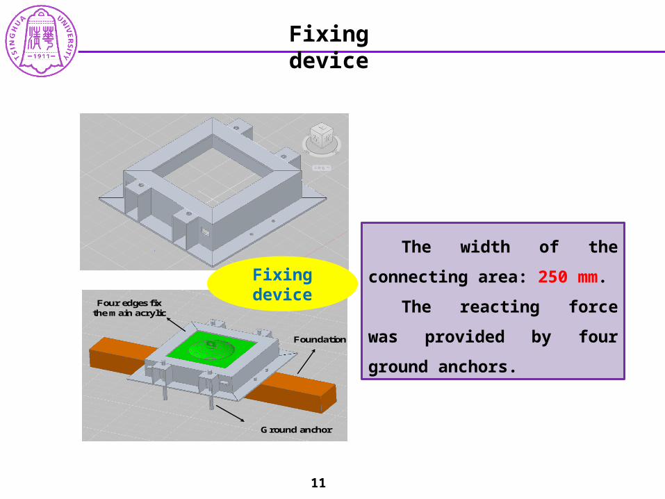
The width of the connecting
area: 250 mm.
The reacting force was
provided by four ground anchors.
Fixing device
Foundation
Ground anchor
Four edges fix the main acrylic
Fixing device
11
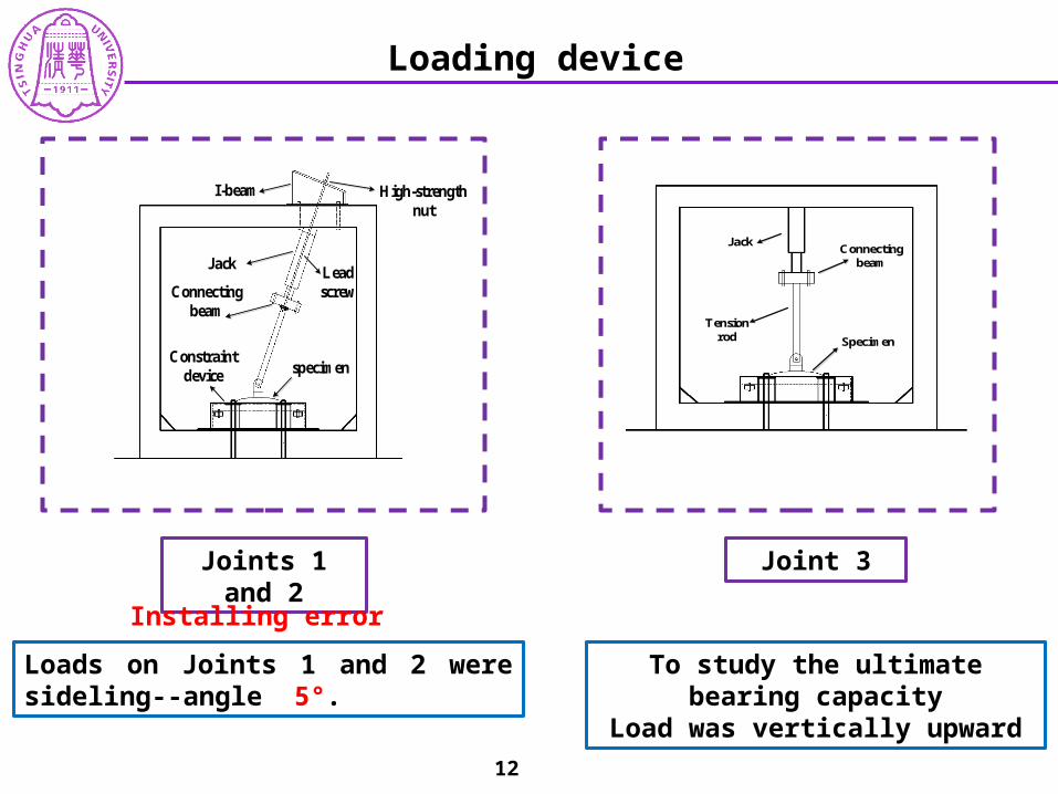
Joints 1 and 2
Loads on Joints 1 and 2 were sideling--angle 5°.
Lead screw
High-strength nut
I-beam
Jack
Connecting beam
specimenConstraint
device
Loading device
Joint 3
To study the ultimate bearing capacityLoad was vertically upward
JackConnecting
beam
Tension rod Specimen
Installing error
12
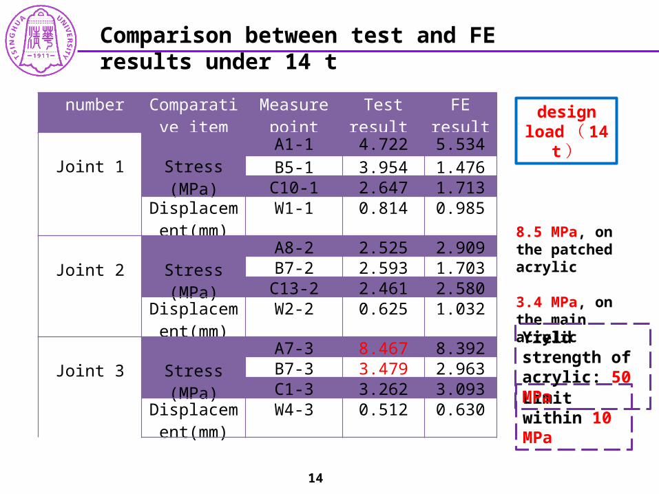
Comparison between test and FE results under 14 t
design load ( 14
t )
number Comparative item
Measure point
Test result FE result
Joint 1
Stress (MPa)
A1-1 4.722 5.534
B5-1 3.954 1.476C10-1 2.647 1.713
Displacement(mm)
W1-1 0.814 0.985
Joint 2
Stress (MPa)
A8-2 2.525 2.909B7-2 2.593 1.703
C13-2 2.461 2.580Displacement
(mm)W2-2 0.625 1.032
Joint 3
Stress (MPa)
A7-3 8.467 8.392B7-3 3.479 2.963C1-3 3.262 3.093
Displacement(mm)
W4-3 0.512 0.630
8.5 MPa, on the patched acrylic
3.4 MPa, on the main acrylic
Limit within 10 MPa
14
Yield strength of acrylic: 50 MPa
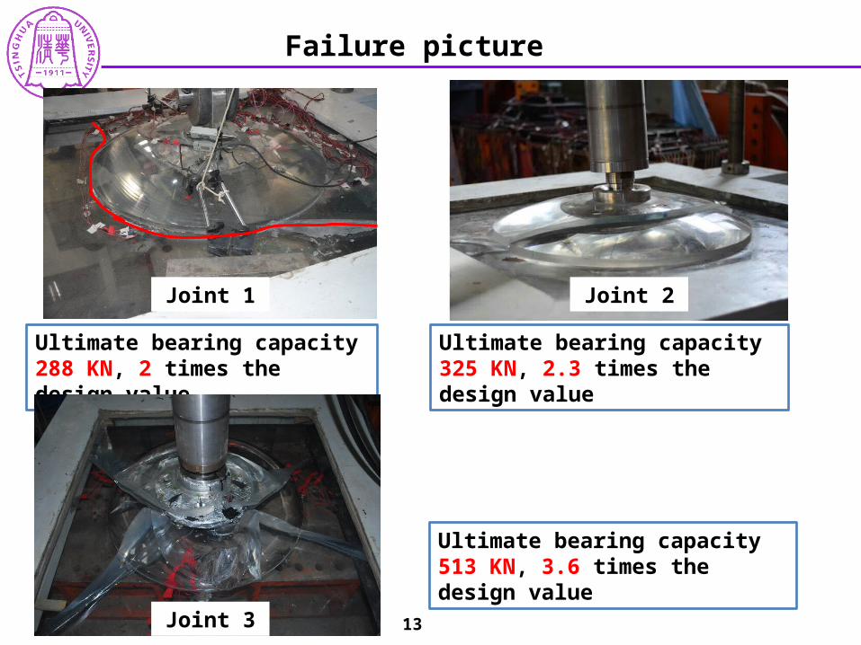
Joint 1
Ultimate bearing capacity 288 KN, 2 times the design value
Failure picture
Joint 2
Ultimate bearing capacity 325 KN, 2.3 times the design value
Joint 3
Ultimate bearing capacity 513 KN, 3.6 times the design value
13
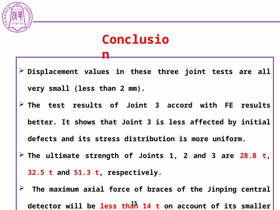
Displacement values in these three joint tests are all very small (less than 2 mm).
The test results of Joint 3 accord with FE results better. It shows that Joint 3 is
less affected by initial defects and its stress distribution is more uniform.
The ultimate strength of Joints 1, 2 and 3 are 28.8 t, 32.5 t and 51.3 t,
respectively.
The maximum axial force of braces of the Jinping central detector will be less
than 14 t on account of its smaller scale. This kind of joint is reliable.
Conclusion
15
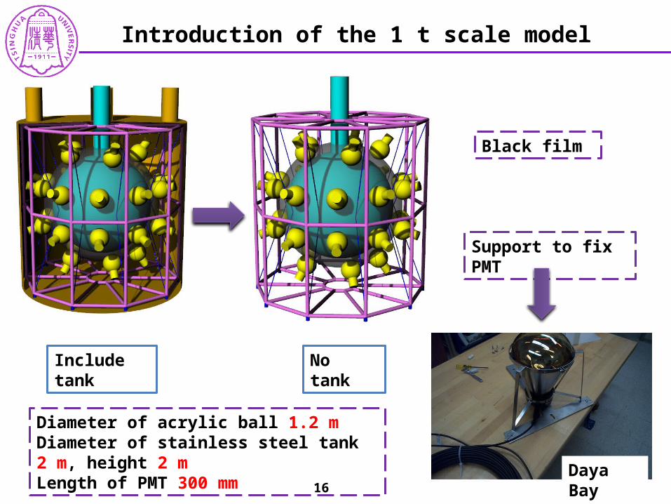
Black film
Support to fix PMT
Include tank No tank
Diameter of acrylic ball 1.2 mDiameter of stainless steel tank 2 m, height 2 mLength of PMT 300 mm
Introduction of the 1 t scale model
Daya Bay16

Thanks!


![[12월 번역 Meetup] Hands on-lab 오픈스택: 번역으로 contributor 활동하기](https://img.pdfslide.tips/doc/110x75/587155011a28ab8e5b8b4f37/12-meetup-hands-on-lab-.jpg)


![At Contributor - [email protected] - Università degli Studi di Padova](https://img.pdfslide.tips/doc/110x75/62407663982b8b0b906a1006/at-contributor-emailprotected-universit-degli-studi-di-padova.jpg)