Embed Size (px)
Citation preview
Federal Highway Administration 10 March 2015 Page 1 of 10
Subject: Dr. Witczak’s letter to AASHTO Subcommittee on Materials and AASHTO Joint Technical Committee on Pavements Issue: Dr. Witczak questioning the validity of dynamic complex modulus (|E*|) measurements utilizing the asphalt mixture performance tester (AMPT) specimen instrumentation protocols. Background: Dr. Witczak’s criticism centers on the current AMPT equipment’s linear variable differential transformer (LVDT) instrumentation requirements which have been modified and updated subsequent to his original LVDT instrumentation recommendation provided in AASHTO standard T 342. Specifically, the general servo-hydraulic testing equipment standard shows LVDT instrumentation examples using “alignment guide rods” in the figures, and specifies a 101.6 ± 1 mm gauge length. The AMPT standards and equipment specifications do not use guide rods and specifies a 70 ± 1 mm gauge length. Through his consulting company, ZW Consulting LLC, and in partnership with GCTS Testing Systems, Dr. Witczak initiated a comparative study of asphalt mixture |E*| measurements. The comparison test data was collected on an AMPT device manufactured by IPC Global and an “E* dynamic testing unit” manufactured by GCTS. This comparative study and an additional internal GCTS study resulted in Dr. Witczak sending a letter to the AAHSTO Subcommittee on Materials and AASHTO Joint Technical Committee on Pavements criticizing the AMPT equipment instrumentation protocols. The IPC device uses testing standards developed after NCHRP Project 9-29 for AMPT test equipment codified within:
1. AASHTO TP 79-13 Standard Method of Test for Determining the Dynamic Modulus and Flow Number for Asphalt Mixtures Using the Asphalt Mixture Performance Tester (AMPT)
2. AASHTO PP 61-13 Standard Practice for Developing Dynamic Modulus Master Curves for Asphalt Mixtures Using the Asphalt Mixture Performance Tester (AMPT)
3. AASHTO PP 60-14 Standard Practice for Preparation of Cylindrical Performance Test Specimens Using the Superpave Gyratory Compactor (SGC)
4. Equipment Specification for the Simple Performance Test System, Version 3.0, October 16, 2007, NCHRP Report 629
The GCTS device uses a testing standard developed prior to NCHRP Project 9-29 for any servo-hydraulic testing equipment system capable of measuring |E*| codified within:
1. AASHTO T 342-11 Standard Method of Test for Determining Dynamic Modulus of Hot Mix Asphalt (HMA)
Dr. Witczak asserts the alignment guide rods and 101.6 mm gauge length should be requirements for |E*| testing because 1) specimen bulging occurs at high temperatures which requires alignment guide rods to always ensure vertical deformation measurements, and 2) the 101.6 mm gauge length requirement is a direct result of his efforts to develop the test procedure for a broad range of asphalt mixtures.
Federal Highway Administration 10 March 2015 Page 2 of 10
Dr. Witczak asserts the LVDT instrumentation difference is a “critical issue” when measuring |E*| at high test temperatures and low rates of loading. Resulting in “unconservative” dynamic modulus master curves and three times larger rut depth predictions from AASHTO PavementME (formerly MEPDG) distress prediction software. History: Dr. Witczak was the principle investigator on National Cooperative Highway Research Program (NCHRP) Project 9-19 Superpave Support and Performance Models Management. The result of this effort recommended the |E*| test as a “simple performance test” for Superpave mix design. The project’s final report is documented in NCHRP Report 547. Additional NCHRP Project 9-19 findings are published as NCHRP Reports:
1. Report 465 Simple Performance Test for Superpave Mix Design 2. Report 547 Simple Performance Tests: Summary of Recommended Methods and
Database 3. Report 580 Specification Criteria for Simple Performance Tests for Rutting, Volume I:
Dynamic Modulus (E*) and Volume II: Flow Number and Flow Time Dr. Ramon Bonaquist, Advanced Asphalt Technologies, LLC was the principle investigator on the subsequent NCHRP Project 9-29 Simple Performance Tester for Superpave Mix Design. This effort was initiated to design, procure, and evaluate “simple performance testers” equipment to measure |E*|. The simple performance testers built to meet the developed criteria is now available from several commercial sources as the Asphalt Mixture Performance Tester (AMPT). Additional NCHRP Project 9-29 findings are published as NCHRP Reports:
1. Report 513 Simple Performance Tester for Superpave Mix Design: First-Article Development and Evaluation
2. Report 530 Evaluation of Indirect Tensile Test (IDT) Procedures for Low-Temperature Performance of Hot Mix Asphalt
3. Report 614 Refining the Simple Performance Tester for Use in Routine Practice 4. Report 629 Ruggedness Testing of the Dynamic Modulus and Flow Number Tests with
the Simple Performance Tester 5. Report 702 Precision of the Dynamic Modulus and Flow Number Tests Conducted with
the Asphalt Mixture Performance Tester Discussion: LVDT Alignment Guide Rod System The LVDT alignment guide rod system is embedded in the development of performance tests during the beginning stages of NCHRP Project 9-191,2 where methods to measure large permanent deformations and small-strain dynamic modulus material properties were explored. 1 Superpave Models Team (1999), Task F Team Report SLS-3, Vols. I, II, and III Tech Reports, Specimen Geometry and Aggregate Size Lab Test Study, NCHRP Report 547, Project 9-19, Ancillary Reports on DVD #CRP-CD-46 2 Witczak, M.W., Bonaquist, R., Von Quintus, H., Kaloush, K., (2000) “Specimen Geometry and Aggregate Size Effects in Uniaxial Compression and Constant Height Shear Tests,” Journal of the Association of Asphalt Paving Technologists, Vol. 69, Page 733-793.
Federal Highway Administration 10 March 2015 Page 3 of 10
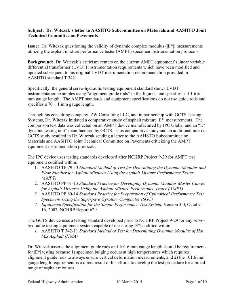
The research was aware of the edge effects occurring at the top and bottom of test specimens in the vicinity of the loading platens where a resultant “barreling” of the test specimen could be observed where the center of the specimen bulges outward into the shape of a barrel. This barreling is caused by free radial dilation near the center and restrained deformation at the specimen ends where it meets the platen; see Figure 13.
(a) (b)
Figure 1. Performance test specimens utilized in early stages of NCHRP 9-19(3). Images show prototype LVDT attachment brackets with “barreled” specimens; Note: (a) no end lubrication and
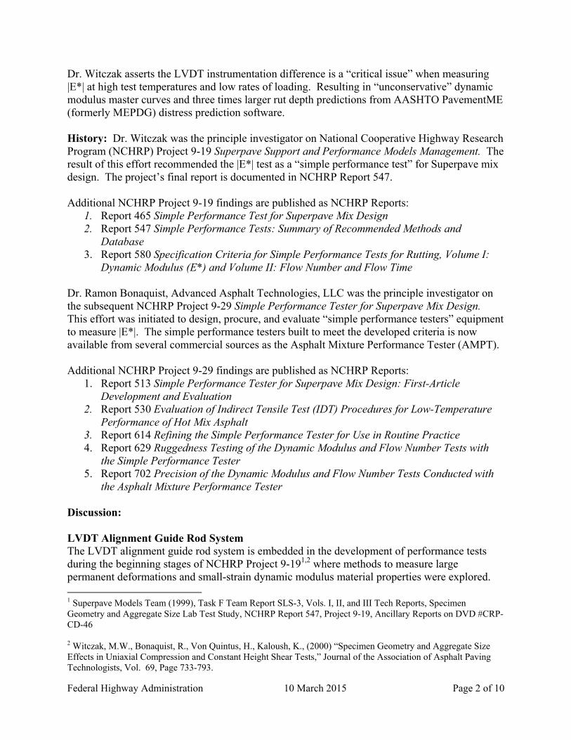
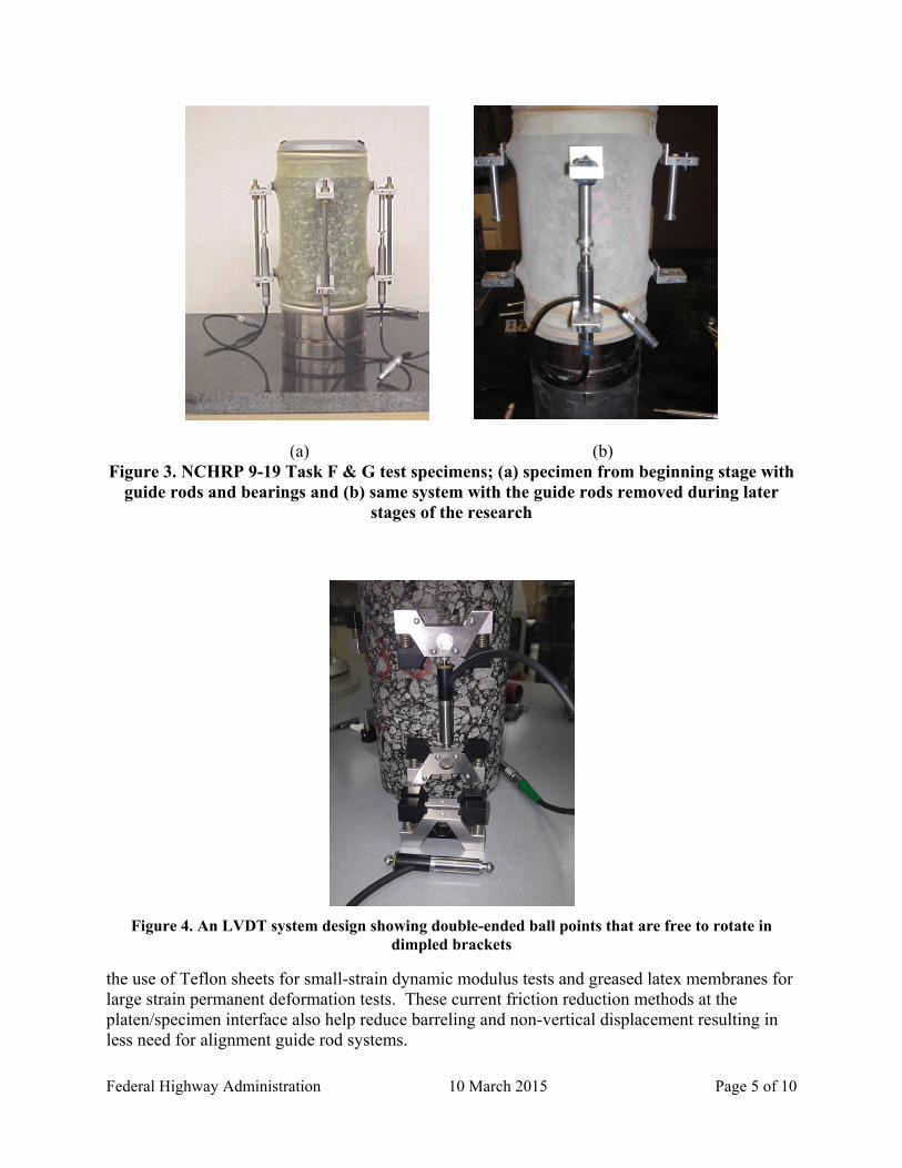
use of concrete cylinder sulfur capping compound and (b) clamped ring brackets Due to the barreling effect, the focus was set on recommending non-intrusive deformation sensors mounted over the center of the specimen located away from the platen/specimen interface. The use of guide rods with linear bearings was incorporated into the design of an LVDT system that was intended to improve the quality of the measured deformation such that it would help capture more of the vertical (axial) deformation component and minimize non-vertical deformations that could influence the measurement as a result of the specimen barreling. See Figure 2. Tasks F&G of the NCHRP 9-19 project involved measuring the dynamic modulus, cracking damage, and permanent deformations to calibrate advanced material models for performance prediction. AMPT equipment did not exist at the time and the Tasks F&G research team used universal test machines for the testing. The team used the previously-recommended LVDT guide rods with linear bearings in the beginning stages of NCHRP Project 9-19 Tasks F&G. A photograph of a sample from that research is shown in Figure 3a. Based on visual observations of the test specimens with extreme deformations during high temperature tests, the alignment guide rod and linear bearing system was a hindrance and not effective because of binding and creating unintended friction resulting in smaller measured vertical deformation and therefore a higher modulus. The team decided to eliminate the
3 Superpave Models Team (1999), Effects of Aggregate Size and Specimen Geometry on HMA Mixtures Properties, Internal Team Report, NCHRP Report 547, Project 9-19, Ancillary Reports on DVD #CRP-CD-46
Federal Highway Administration 10 March 2015 Page 4 of 10
(a) (b)
Figure 2. LVDT guide rod and linear bearing configurations; (a) proposed system by Superpave Models Team in 1999 and (b) general schematic diagramed in AASHTO T 342
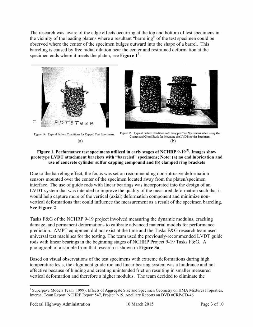
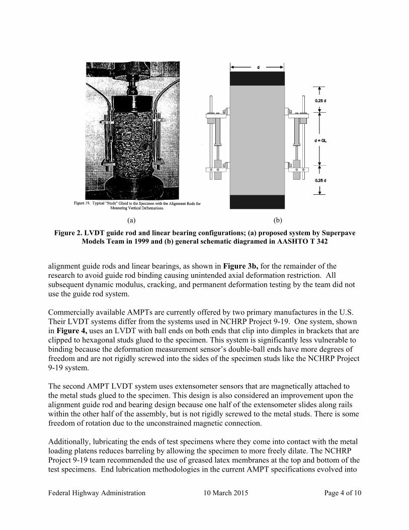
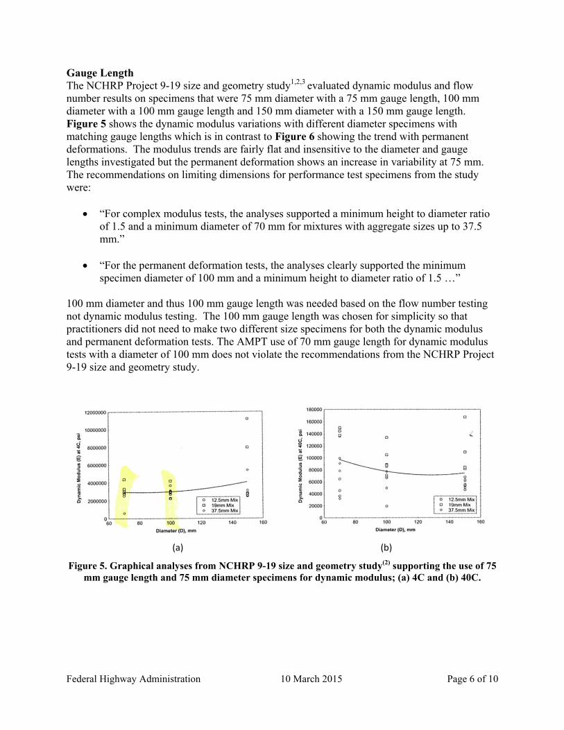
alignment guide rods and linear bearings, as shown in Figure 3b, for the remainder of the research to avoid guide rod binding causing unintended axial deformation restriction. All subsequent dynamic modulus, cracking, and permanent deformation testing by the team did not use the guide rod system. Commercially available AMPTs are currently offered by two primary manufactures in the U.S. Their LVDT systems differ from the systems used in NCHRP Project 9-19. One system, shown in Figure 4, uses an LVDT with ball ends on both ends that clip into dimples in brackets that are clipped to hexagonal studs glued to the specimen. This system is significantly less vulnerable to binding because the deformation measurement sensor’s double-ball ends have more degrees of freedom and are not rigidly screwed into the sides of the specimen studs like the NCHRP Project 9-19 system. The second AMPT LVDT system uses extensometer sensors that are magnetically attached to the metal studs glued to the specimen. This design is also considered an improvement upon the alignment guide rod and bearing design because one half of the extensometer slides along rails within the other half of the assembly, but is not rigidly screwed to the metal studs. There is some freedom of rotation due to the unconstrained magnetic connection. Additionally, lubricating the ends of test specimens where they come into contact with the metal loading platens reduces barreling by allowing the specimen to more freely dilate. The NCHRP Project 9-19 team recommended the use of greased latex membranes at the top and bottom of the test specimens. End lubrication methodologies in the current AMPT specifications evolved into
Federal Highway Administration 10 March 2015 Page 5 of 10
(a) (b) Figure 3. NCHRP 9-19 Task F & G test specimens; (a) specimen from beginning stage with
guide rods and bearings and (b) same system with the guide rods removed during later stages of the research
Figure 4. An LVDT system design showing double-ended ball points that are free to rotate in
dimpled brackets
the use of Teflon sheets for small-strain dynamic modulus tests and greased latex membranes for large strain permanent deformation tests. These current friction reduction methods at the platen/specimen interface also help reduce barreling and non-vertical displacement resulting in less need for alignment guide rod systems.
Federal Highway Administration 10 March 2015 Page 6 of 10
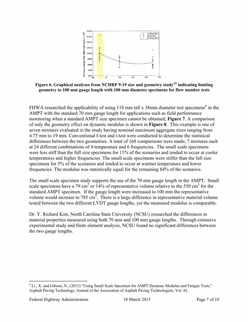
Gauge Length The NCHRP Project 9-19 size and geometry study1,2,3 evaluated dynamic modulus and flow number results on specimens that were 75 mm diameter with a 75 mm gauge length, 100 mm diameter with a 100 mm gauge length and 150 mm diameter with a 150 mm gauge length. Figure 5 shows the dynamic modulus variations with different diameter specimens with matching gauge lengths which is in contrast to Figure 6 showing the trend with permanent deformations. The modulus trends are fairly flat and insensitive to the diameter and gauge lengths investigated but the permanent deformation shows an increase in variability at 75 mm. The recommendations on limiting dimensions for performance test specimens from the study were:
“For complex modulus tests, the analyses supported a minimum height to diameter ratio of 1.5 and a minimum diameter of 70 mm for mixtures with aggregate sizes up to 37.5 mm.”
“For the permanent deformation tests, the analyses clearly supported the minimum
specimen diameter of 100 mm and a minimum height to diameter ratio of 1.5 …” 100 mm diameter and thus 100 mm gauge length was needed based on the flow number testing not dynamic modulus testing. The 100 mm gauge length was chosen for simplicity so that practitioners did not need to make two different size specimens for both the dynamic modulus and permanent deformation tests. The AMPT use of 70 mm gauge length for dynamic modulus tests with a diameter of 100 mm does not violate the recommendations from the NCHRP Project 9-19 size and geometry study.
(a) (b)
Figure 5. Graphical analyses from NCHRP 9-19 size and geometry study(2) supporting the use of 75 mm gauge length and 75 mm diameter specimens for dynamic modulus; (a) 4C and (b) 40C.
Federal Highway Administration 10 March 2015 Page 7 of 10
Figure 6. Graphical analyses from NCHRP 9-19 size and geometry study(2) indicating limiting
geometry to 100 mm gauge length with 100 mm diameter specimens for flow number tests
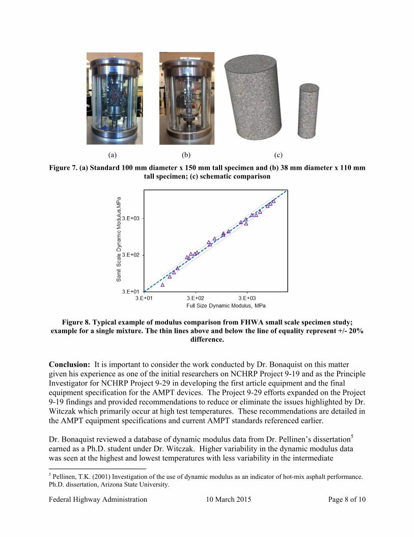
FHWA researched the applicability of using 110 mm tall x 38mm diameter test specimens4 in the AMPT with the standard 70 mm gauge length for applications such as field performance monitoring when a standard AMPT size specimen cannot be obtained; Figure 7. A comparison of only the geometry effect on dynamic modulus is shown in Figure 8. This example is one of seven mixtures evaluated in the study having nominal maximum aggregate sizes ranging from 4.75 mm to 19 mm. Conventional f-test and t-test were conducted to determine the statistical differences between the two geometries. A total of 168 comparisons were made; 7 mixtures each at 24 different combinations of 4 temperature and 6 frequencies. The small scale specimens were less stiff than the full size specimens for 11% of the scenarios and tended to occur at cooler temperatures and higher frequencies. The small scale specimens were stiffer than the full size specimens for 5% of the scenarios and tended to occur at warmer temperature and lower frequencies. The modulus was statistically equal for the remaining 84% of the scenarios. The small scale specimen study supports the use of the 70 mm gauge length in the AMPT. Small scale specimens have a 79 cm3 or 14% of representative volume relative to the 550 cm3 for the standard AMPT specimen. If the gauge length were increased to 100 mm the representative volume would increase to 785 cm3. There is a large difference in representative material volume tested between the two different LVDT gauge lengths, yet the measured modulus is comparable. Dr. Y. Richard Kim, North Carolina State University (NCSU) researched the differences in material properties measured using both 70 mm and 100 mm gauge lengths. Through extensive experimental study and finite element analysis, NCSU found no significant differences between the two gauge lengths.
4 Li., X. and Gibson, N., (2013) “Using Small Scale Specimen for AMPT Dynamic Modulus and Fatigue Tests,” Asphalt Paving Technology, Journal of the Association of Asphalt Paving Technologists, Vol. 82.
Federal Highway Administration 10 March 2015 Page 8 of 10
(a) (b) (c)
Figure 7. (a) Standard 100 mm diameter x 150 mm tall specimen and (b) 38 mm diameter x 110 mm tall specimen; (c) schematic comparison
Figure 8. Typical example of modulus comparison from FHWA small scale specimen study; example for a single mixture. The thin lines above and below the line of equality represent +/- 20%
difference.
Conclusion: It is important to consider the work conducted by Dr. Bonaquist on this matter given his experience as one of the initial researchers on NCHRP Project 9-19 and as the Principle Investigator for NCHRP Project 9-29 in developing the first article equipment and the final equipment specification for the AMPT devices. The Project 9-29 efforts expanded on the Project 9-19 findings and provided recommendations to reduce or eliminate the issues highlighted by Dr. Witczak which primarily occur at high test temperatures. These recommendations are detailed in the AMPT equipment specifications and current AMPT standards referenced earlier. Dr. Bonaquist reviewed a database of dynamic modulus data from Dr. Pellinen’s dissertation5 earned as a Ph.D. student under Dr. Witczak. Higher variability in the dynamic modulus data was seen at the highest and lowest temperatures with less variability in the intermediate 5 Pellinen, T.K. (2001) Investigation of the use of dynamic modulus as an indicator of hot-mix asphalt performance. Ph.D. dissertation, Arizona State University.
Federal Highway Administration 10 March 2015 Page 9 of 10
temperatures. The alignment guide rod and bearing system was identified as a potential cause due to friction in the guide rod at high test temperatures. An alignment guide rod system was not included as a requirement in developing first article prototypes equipment. This did not prevent first article equipment manufacturers from independently proposing such a guide rod and linear bearing system. However, none proposed this system. Current AMPTs also utilize a variety of data quality indicators to ensure the stress and strain waveforms are properly shaped and an acceptable amount of baseline creep is not occurring in the strain from various sources in the testing methodology. A source of this creep could be the spring force in the LVDT/extensometer pushing the studs apart, too high of a test temperature relative to the stiffness of the asphalt binder in the mix, the weight of the LVDT or extensometer assembly itself, the additional weight provided by an alignment guide rod system, or combinations of these sources. The ruggedness study conducted in NCHRP Project 9-29 included an equipment effects experiment. In the experiment it was found the size of the gauge points and reverse drift caused by the LVDT spring force in some AMPT systems moved the gauge points apart during testing at high temperature. The gauge point movement could result in modulus differences on the order of 30 percent. The gauge point movement was particularly a problem with one system discovered to have high LVDT spring force. The use of external springs to counteract the LVDT spring force was investigated and when used properly, gauge point movement was minimized. AMPT manufactures have revised equipment over time and reduced the spring force in the sensor to eliminate these effects. To address the gauge point movement issue, the equipment specification for the AMPT limits the size of the glued gauge points and deformation measurement system to minimize the mass; and AASHTO TP79 includes a data quality check to ensure the deformation drift is in the direction of the applied load to eliminate data where the gauge points are moving apart. The differences cited in modulus values at high temperatures would not be as large if the data quality indicators included in the current AMPT standards were enforced. Data quality indicator checks are included in the standards to minimize the potential for gauge point movement known to cause low modulus values. Additionally, the recommended test temperatures in AASHTO PP61 were selected to minimize the potential for gauge point movement at high temperatures by recommending maximum temperatures of 35°C for PG 58 and softer, 40°C for PG 64 and PG 70, and 45 °C for and PG 76 and stiffer binders. The differences cited in modulus values at high temperatures would not be as large if the temperature recommendations included in the current AMPT standards are followed. Furthermore, many of the data points used in the original predictive model calibration were obtained long before AMPT equipment was developed. The cited agreement between the predictive equation and the dynamic modulus data obtained from specimens using the alignment guide rod and bearing system does not support the claim that it is providing a more correct measure in the laboratory. Rather, this original predictive equation was calibrated with laboratory measurement systems developed prior to the AMPT.

Federal Highway Administration 10 March 2015 Page 10 of 10
Consequently, based on the development discussed previously, additional study or comparisons of the current AMPT instrumentation system is not justified. The issues with high temperature testing cited are inherently caused by the use of on specimen glued gauge point systems; not the gauge length or requiring the use of alignment guide rods. If additional study of dynamic modulus measurement instrumentation is under consideration, it should focus on investigating the AMPT manufacturer’s capabilities to use a non-contact measurement system which do not require on specimen gauge points. NCHRP Project 9-29 initially discussed non-contact systems with manufacturers during the early stages of the project. The original equipment specification allowed non-contact devices and its use was encouraged. At that time, a non-contact system was not economically feasible for use in the AMPT equipment. Perhaps advancements in the technology and manufacturing warrant a second look at these systems to determine if they are cost effective.