Embed Size (px)
Citation preview
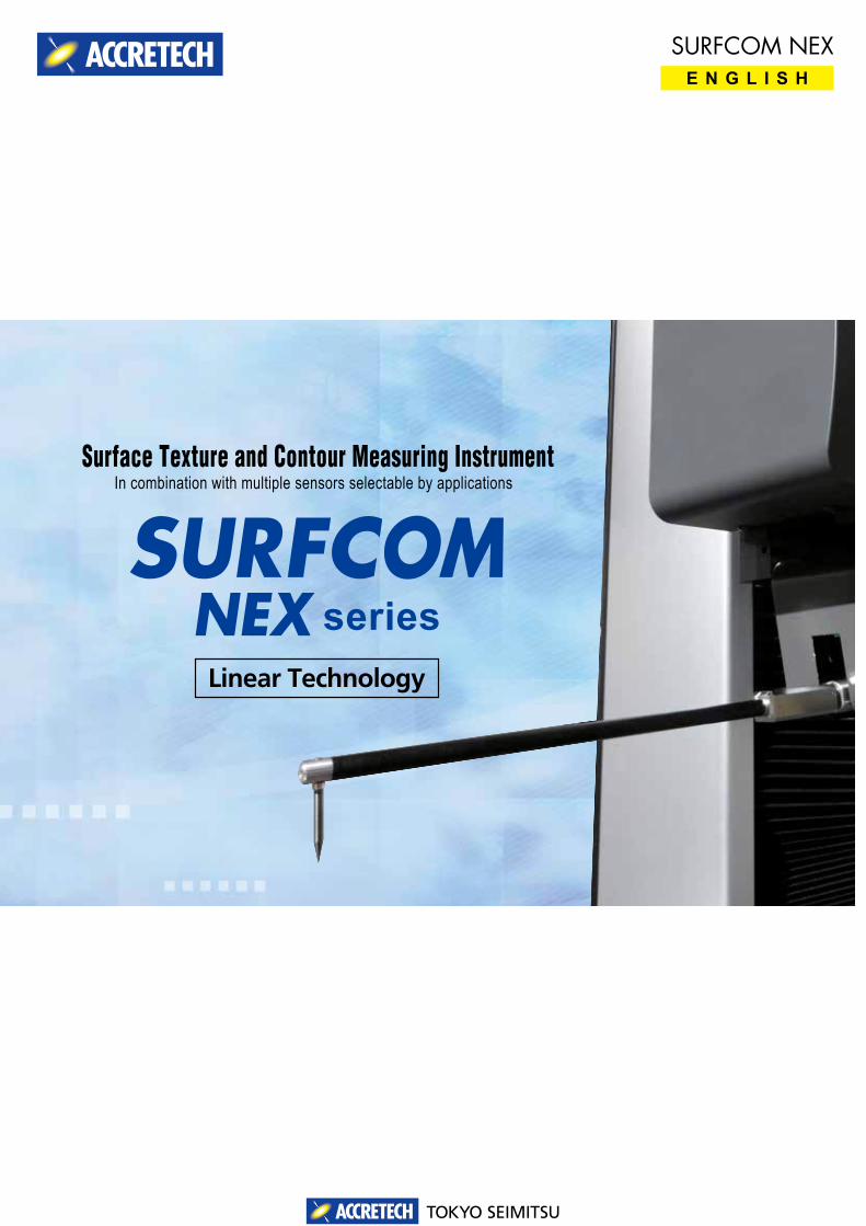
E N G L I S HSURFCOM NEX
Surface Texture and Contour Measuring Instrument
Linear Technology
series
In combination with multiple sensors selectable by applications
TOKYO SEIMITSU
TOKYO SEIMITSU1
Feature
Feature
Feature
Feature
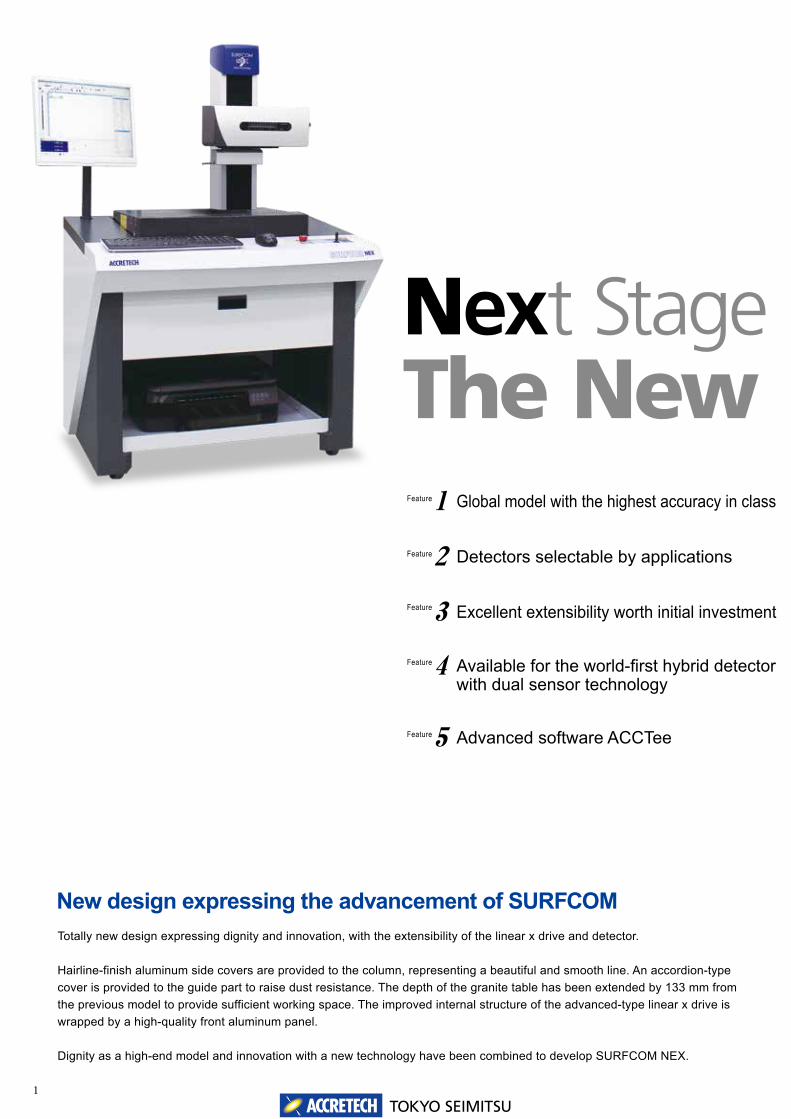
New design expressing the advancement of SURFCOMTotally new design expressing dignity and innovation, with the extensibility of the linear x drive and detector.
Hairline-finish aluminum side covers are provided to the column, representing a beautiful and smooth line. An accordion-type cover is provided to the guide part to raise dust resistance. The depth of the granite table has been extended by 133 mm from the previous model to provide sufficient working space. The improved internal structure of the advanced-type linear x drive is wrapped by a high-quality front aluminum panel.
Dignity as a high-end model and innovation with a new technology have been combined to develop SURFCOM NEX.
Next StageThe New SURFCOM NEX1 Global model with the highest accuracy in class
2 Detectors selectable by applications
3 Excellent extensibility worth initial investment
4 Available for the world-first hybrid detector with dual sensor technology
5 Advanced software ACCTee
Feature
TOKYO SEIMITSU2
New design expressing the advancement of SURFCOM
Next StageThe New SURFCOM NEX
Global model with the highest accuracy in class
Detectors selectable by applications
Excellent extensibility worth initial investment
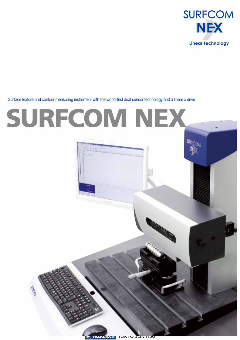
Surface texture and contour measuring instrument with the world-first dual sensor technology and a linear x drive
TOKYO SEIMITSU3
Hybrid Contour Roughness
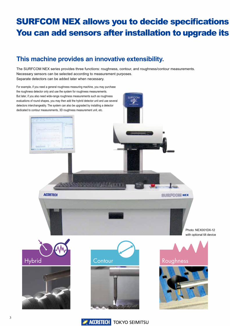
SURFCOM NEX allows you to decide specifications by selecting necessary detectors.You can add sensors after installation to upgrade its ability.
Photo: NEX001DX-12 with optional tilt device
This machine provides an innovative extensibility.The SURFCOM NEX series provides three functions: roughness, contour, and roughness/contour measurements. Necessary sensors can be selected according to measurement purposes. Separate detectors can be added later when necessary.
For example, if you need a general roughness measuring machine, you may purchase the roughness detector only and use the system for roughness measurements. But later, if you also need wide-range roughness measurements such as roughness evaluations of round shapes, you may then add the hybrid detector unit and use several detectors interchangeably. The system can also be upgraded by installing a detector dedicated to contour measurements, 3D roughness measurement unit, etc.

TOKYO SEIMITSU4
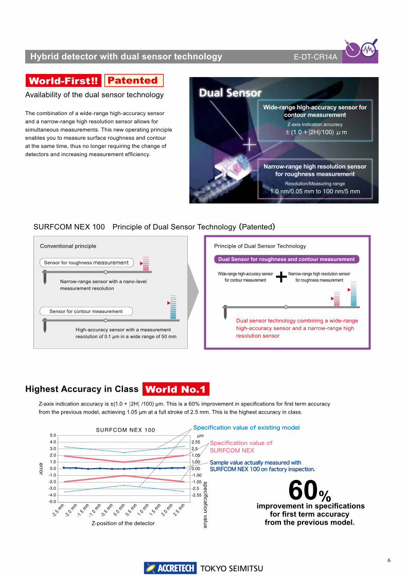
Hybrid detector with dual sensor technologyE-DT-CR14A
▲
page 5 to 6
Contour detectorE-DT-CH18A
General purpose detector equipped with a newly-developed high-precision scale. The Z-axis measurement range is 60 mm. Stress-free replacement is possible with the newly-developed Quick-change mechanism of arm. Upward/downward measurements are optionally available.
▲
Upper part of page 9
High-accuracy contour detector with automatic measuring force adjustment mechanismE-DT-CH19A
High accuracy type detector equipped with a new laser diffraction linear scale. The full-range measurement resolution is 0.02 μm. It features an automatic adjustment mechanism of measuring force as well as the Z-axis measurement range of 60 mm and Quick-change arm mechanism. Upward/downward measurement is optionally available.
▲
Lower part of page 9
Pickup for roughness measurementE-DT-SS01A
▲
P.11
SURFCOM NEX allows you to decide specifications by selecting necessary detectors.You can add sensors after installation to upgrade its ability.
Multiple sensors are available.Detectors can be selected by application.This machine offers hybrid, roughness, contour, and combined functions.
The SURFCOM NEX series allows you to select detectors by application. Detectors can be used as a single detector or combined with others to serve as multiple sensors.
An integrated measuring instrument with newly developed dual sensor technology capable of measuring roughness and contour simultaneously. Please refer to the next page for details.
A pickup with compact design for high magnification and wide-range measurements. Its outer diameter is 14 mm, measurement range is 1000 μm, and its maximum measurement magnification is 500,000 times. It is used for pickup upward measurements (with the auto-stop function) and horizontal trace measurements.

TOKYO SEIMITSU5
World-first! Hybrid detector with dual sensor technology.The world-first hybrid detector with the dual sensor technology ACCRETECH has developed (patent obtained). Unlike the conventional detector, it has a high-accuracy linear Z scale for wide-range measurements and a high resolution differential inductance for narrow-range measurements. Using these two sensors simultaneously in measurement maximizes their performance.
This new type hybrid detector is compatible with the previous model series (DX2/SD2 and after).
TOKYO SEIMITSU6
Highest Accuracy in Class
World-First!! Patented
60% improvement in specifications
for first term accuracy from the previous model.Z-position of the detector
Z-axis indication accuracy is ±(1.0 + |2H| /100) μm. This is a 60% improvement in specifications for first term accuracy from the previous model, achieving 1.05 μm at a full stroke of 2.5 mm. This is the highest accuracy in class.
Hybrid detector with dual sensor technology E-DT-CR14A
Availability of the dual sensor technology
The combination of a wide-range high-accuracy sensor and a narrow-range high resolution sensor allows for simultaneous measurements. This new operating principle enables you to measure surface roughness and contour at the same time, thus no longer requiring the change of detectors and increasing measurement efficiency.
Dual SensorWide-range high-accuracy sensor for
contour measurementZ-axis indication accuracy
± (1.0+ |2H|/100) μm
Narrow-range high resolution sensor for roughness measurement
Resolution/Measuring range
1.0 nm/0.05 mm to 100 nm/5 mm
SURFCOM NEX 100 Principle of Dual Sensor Technology (Patented)
Conventional principle Principle of Dual Sensor Technology
Sensor for roughness measurement
Sensor for contour measurement
Narrow-range sensor with a nano-level measurement resolution
High-accuracy sensor with a measurement resolution of 0.1 μm in a wide range of 50 mm
Narrow-range high resolution sensor for roughness measurement
Dual sensor technology combining a wide-range high-accuracy sensor and a narrow-range high resolution sensor
Wide-range high-accuracy sensor for contour measurement
World No.1
Dual Sensor for roughness and contour measurement
error
specification value
Specification value of SURFCOM NEX
Specification value of existing model
Sample value actually measured with SURFCOM NEX 100 on factory inspection.
2.55
2.5
1.05
1.00
0.00
-1.00
-1.05
-2.5
-2.55
5.0
4.0
3.0
2.0
1.0
0.0
-1.0
-2.0
-3.0
-4.0
-5.0
μm
-2.5
mm
-2.0
mm
-1.5
mm
-1.0
mm
-0.5
mm
0.0
mm0.
5 mm
1.0
mm1.
5 mm
2.0
mm2.
5 mm
SURFCOM NEX 100

7TOKYO SEIMITSU
Temperature correction system provides you the accuracy guaranteed temperature range to 20°C ± 5°CThe NEX series drive with scale temperature correction technology.provides. The each accuracy guaranteed temperature range of the system was expand to 20°C ± 5°C from 20°C ± 2°C.
Conventionally, expansion and contraction of the drive's scale by temperature change affected the indication accuracy for X direction. However, it can be corrected automatically in real time by having a temperature sensor.
This is a special function only for NEX series with the combination of the temperature correction system and each detector which is less affected by temperature change.
Detector for contour measurement offering excellent convenience by incorporating linear drive with a temperature correction system.This is the evolution into the ultimate refinement without compromises to make high accuracy a common thing.
1Feature
X-ax
is ind
icatio
n ac
cura
cy (μ
m)
X-axis tracing driver indication accuracy
measurering position (mm)
-3.00
-2.00
-1.00
0.00
1.00
2.00
3.00
0 20 40 60 80 100
15℃ 20℃ 25℃
8TOKYO SEIMITSU
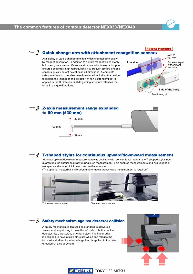
3 Z-axis measurement range expanded to 60 mm (±30 mm)
2 Quick-change arm with attachment recognition sensorsAvailability of Quick-change function which changes arm easily by magnet desorption. In addition to double magnet which stably holds arm, the crossing V-groove structure with three-part support ensures extremely high reproducibility. Moreover, sphere-shaped sensors quickly detect deviation in all directions. A complete safety mechanism has also been introduced including the design to reduce the impact on the detector: When a strong impact is applied in the X direction, a slide guiding structure releases the force in oblique directions.
4 T-shaped stylus for continuous upward/downward measurementAlthough upward/downward measurement was available with conventional models, the T-shaped stylus now guarantees the spatial accuracy during such measurement. This enables measurements and evaluations of workpieces' diameter, thickness, uneven thickness, etc.(The optional masterball calibration unit for upward/downward measurement is required.)
5 Safety mechanism against detector collisionA safety mechanism is featured as standard to activate a sensor and stop driving in case the left side or bottom of the detector hits a workpiece or other object. The linear drive is designed to have a slide structure which can release the force with shaft motor when a large load is applied to the drive direction (X-axis direction) .
+ 30 mm
- 30 mm
60 mm
The common features of contour detector NEX030/NEX040
Patent Pending
Arm side
Side of the body
Cross V groove
Positioning pin
Sphere-shaped attachment sensors
Feature
Feature
Feature
Feature
Diameter measurementThickness measurement
9TOKYO SEIMITSU
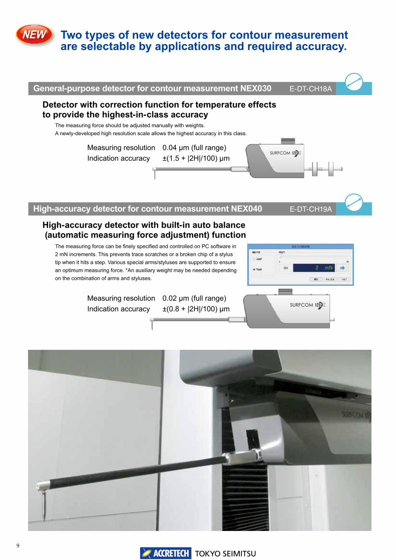
General-purpose detector for contour measurement NEX030 E-DT-CH18A
Detector with correction function for temperature effectsto provide the highest-in-class accuracy
The measuring force should be adjusted manually with weights.A newly-developed high resolution scale allows the highest accuracy in this class.
High-accuracy detector for contour measurement NEX040 E-DT-CH19A
High-accuracy detector with built-in auto balance (automatic measuring force adjustment) function
The measuring force can be finely specified and controlled on PC software in 2 mN increments. This prevents trace scratches or a broken chip of a stylus tip when it hits a step. Various special arms/styluses are supported to ensure an optimum measuring force. *An auxiliary weight may be needed depending on the combination of arms and styluses.
Two types of new detectors for contour measurement are selectable by applications and required accuracy.
Measuring resolution 0.04 μm (full range)Indication accuracy ±(1.5 + |2H|/100) μm
Measuring resolution 0.02 μm (full range)Indication accuracy ±(0.8 + |2H|/100) μm

10TOKYO SEIMITSU
T-shaped stylus option for upward/downward contour measurements
Masterball calibration unit for upward/downward measurementsE-MC-S97A
This is a calibration unit to guarantee the spatial accuracy of upward and downward measurements using SURFCOM NEX 030/040. Use this unit to calibrate the parameters required to set the stylus upward/downward. Arc correction and stylus tip radius correction performed based on the calculated parameter provides advanced measurements.
Dimensions: 150(W) x 120(D) x 230(H) mmWeight: Approx. 3.3 kg
Stylus for upward/downward measurements
The stylus designed for the upward/downward measurement using SURFCOM NEX 030/040.
Two types of new detectors for contour measurement are selectable by applications and required accuracy.
Length Tip radius Edge angle Material
DM83502 L=26 mm rtip=25μm 24° conical Cemented carbide
DM83503 L=32 mm rtip=25μm 24° conical Cemented carbide
DM83504 L=44 mm rtip=25μm 24° conical Cemented carbide
Attachment for Quick change arm (option)
24° conical, rtip=25μm
L
Φ 3 mm
Example of using the Quick-change arm attachment
DM83506
This attachment attaches conventional arms to a quick change type contour measurement detector. You can continue the use of the arms of your conventional measuring instrument to save cost. It is designed to make the total length when combining the attachment and the conventional arms be the same as that of the supplied standard arm. Even when the conventional arm is used, the detector's z-aixs measurement range (60 mm(±30 mm)) can be ensured.For applicable arms, contact our sales representative.

11TOKYO SEIMITSU
Pickup for roughness measurement NEX001 E-DT-SS01A
Just changing the holder direction allows horizontal trace measurements.
The auto stop is also possible for upward measurements.
The optional connecting rod for ultra-long holes
Detector (pickup) dedicated to surface roughness measurement providing unparalleled possibility resulted from our histories as a market leader.When combined with linear x drive, it provides excellent reliability for surface profile evaluation.
φ14
The newly developed pickup supports high magnification and wide range measurements. The compact body with an outside diameter of 14 mm provides the measurement range of 1000 μm and measurement magnification of 500,000x.
The specification of the pickup for roughness measurements is 1000 μm.
This detector offers a measurement range of 1000 μm in the Z direction, which is 25% wider compared with 800 μm of common detectors. It has an excellent wide stroke as a roughness measuring machine.The wide-range measurements significantly reduces the tilt angle ofthe measurement surface and detailed alignment at the R surfacemeasurements (such as shafts, bearing workpieces).
12TOKYO SEIMITSU
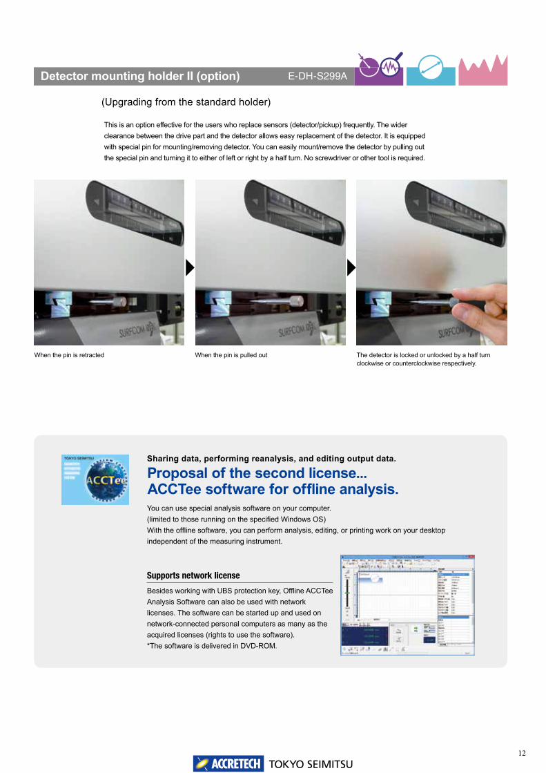
Detector mounting holder II (option)
(Upgrading from the standard holder)
This is an option effective for the users who replace sensors (detector/pickup) frequently. The wider clearance between the drive part and the detector allows easy replacement of the detector. It is equipped with special pin for mounting/removing detector. You can easily mount/remove the detector by pulling out the special pin and turning it to either of left or right by a half turn. No screwdriver or other tool is required.
E-DH-S299A
The specification of the pickup for roughness measurements is 1000 μm.
When the pin is retracted When the pin is pulled out The detector is locked or unlocked by a half turn clockwise or counterclockwise respectively.
Proposal of the second license...ACCTee software for offline analysis.You can use special analysis software on your computer.(limited to those running on the specified Windows OS)With the offline software, you can perform analysis, editing, or printing work on your desktop independent of the measuring instrument.
Supports network license
Besides working with UBS protection key, Offline ACCTee Analysis Software can also be used with network licenses. The software can be started up and used on network-connected personal computers as many as the acquired licenses (rights to use the software). *The software is delivered in DVD-ROM.
Sharing data, performing reanalysis, and editing output data.

TOKYO SEIMITSU
Gear Feed Screw
Carriage
Reference BaseDC
Motor
Linear Motor
Carriage
Reference Base
13
Continually increasing the resolution of a detector is a simple task. However, unless you also improve factors like the structure that drives the detector, unnecessarily raising the resolution of the detector is merely window-dressing the specifications.ACCRETECH is the first company in the world to use a high-accuracy linear motor as the drive motor (patened) in a revolutionary new structure that dramatically pushes the envelope in terms of high accuracy. The result is a dynamic solution that improves actual values to unmatched levels.
■Linear Drive for Amazingly Low Vibration
A linear motor is ideal even for reciprocating motion, and enables accurate positioning and high-speed measuring. Conventional control uses a ball screw drive control system that combines a motor, encoder, and linear scale, which limits the reciprocating motion control response especially when determining accurate positioning during 3D surface evaluation. Linear drive, on the other hand, enables simplified control consisting basically of a linear motor and scale, for high response, high accuracy positioning.
■Effectiveness of the Non-Contact Drive
It is unnecessary to apply grease to or lubricate the drive mechanism on a daily basis. The review of the material and mechanism of the guide surface that supports driving has eliminated the need of daily maintenance. Periodical maintenance (inspection and calibration) is recommended in terms of ensuring the guaranteed accuracy of the instrument.
■Maintenance free
Approach distance is effective when you do not want to waste measuring distance or when you can only measure short distances. With conventional measuring instruments, approach distance is always required before data sampling, while taking backlash and motor startup characteristics into consideration. ACCRETECH linear motor models are designed for high response and zero backlash, which eliminates the need for approach distance.
■Approach Distance
You will find why you need the linear x drive.
Patented
Linear seriesStandard series
Patented
Measurement result of level difference master
Optical flat measurement Calibration certificate of leveldifference master
Response startup speed graph
ApproachDistance
(λ/3−λ)Front end
reserve length
(λ/3−λ)Rear end
reserve lengthEvaluation length
(Reference length:λx5)
(λ/3−λ)Front end
reserve length
(λ/3−λ)Rear end
reserve lengthEvaluation length
(Reference length:λx5)
Actual measured length
Actual measured length
Response Startup Speed Graph
Conv
entio
nal in
strum
ent
Lin
ear
Ser
ies

TOKYO SEIMITSU14
手動送りつまみ
ジョイスティック JOGダイヤル
The manual feed mechanism installed on the X-axis drive is so designed that the connection between the manual gear mechanism and the linear measurement mechanism is automatically cut off in the actual measurements in order not to affect the low vibration characteristics achieved by the linear motor.This results in high operability and accuracy. A jog dial for minute feeding has been laid out in addition to the joy stick in the hand operation section to ensure that subtle positioning can be securely carried out.
■Positioning
The measuring time for 3D roughness measuring is: [1/10 Conventional Measuring Time] x [Number of Measuring Lines], resulting in greatly reduced measuring times. This reduces the risk of measurements being affected by temperature change and other measuring error factors, leading to more reliable measured results.The linear motor and minimal lost motion provided by the 1/100-second link control combine with outstanding start response to deliver dramatic overall reductions in total measuring time.
■World’s Fastest Speed Measurements
The DX Type is designed for much more than simply saving space. Keeping in mind the idea of “Important Functions for Realization of Comfortable Measurement and Analysis,” a COAP concept design derived from ergonomics has been introduced to minimize frequent operator movements while measuring and analysing multiple workpieces. The DX Type also comes complete with essential options, making it an all-in-one package. The Windows computer is stored in the space under the vibration isolation stand, to provide a high level of environmental resistance. Dead space on the right side of the column is also put to use by providing a storage box that can be used for system accessories and peripherals. The Windows computer is stored in the space under the vibration isolation stand, to provide a high level of environmental resistance. As a result, the area required for installation is approximately 25% less than the standard installation area of previous models (SD specifications require the same area as previous models).
■The Perfect Combination of Operation and Cost PerformanceC.O.A.P. (Comfortable Operation and All-in-one Package) Design Plan
You will find why you need the linear x drive.
Joystick Jog dial
Patented
DX type SD type
Example of 3D roughness measurementwith linear series and ACCTee
Manual grip
TOKYO SEIMITSU
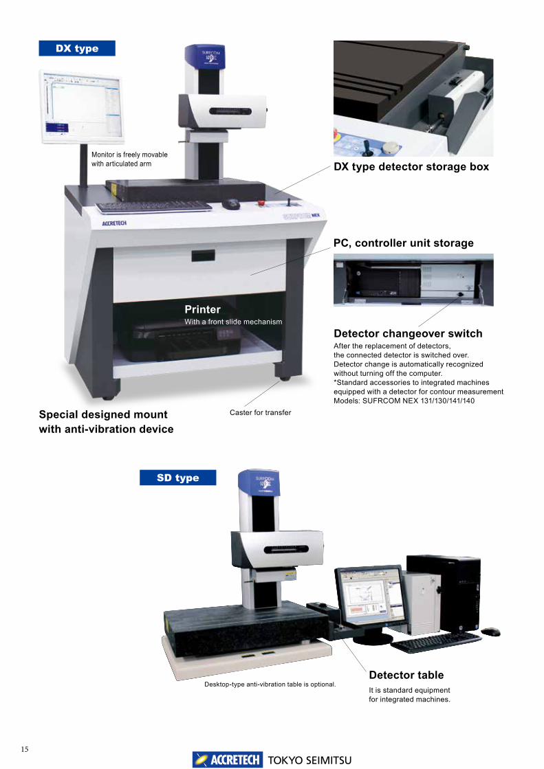
PrinterWith a front slide mechanism
15
DX type detector storage box
SD type
Detector changeover switchAfter the replacement of detectors, the connected detector is switched over. Detector change is automatically recognized without turning off the computer. *Standard accessories to integrated machines equipped with a detector for contour measurementModels: SUFRCOM NEX 131/130/141/140
Detector tableIt is standard equipment for integrated machines.
Desktop-type anti-vibration table is optional.
DX type
PC, controller unit storage
Caster for transferSpecial designed mount with anti-vibration device
Monitor is freely movable with articulated arm
TOKYO SEIMITSU16
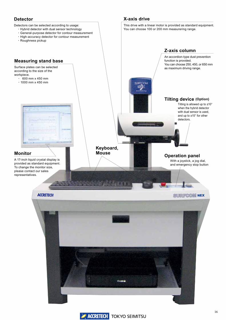
Detector Detectors can be selected according to usage: ・ Hybrid detector with dual sensor technology ・ General-purpose detector for contour measurement ・ High-accuracy detector for contour measurement ・ Roughness pickup
Operation panelWith a joystick, a jog dial,and emergency stop button
X-axis driveThis drive with a linear motor is provided as standard equipment. You can choose 100 or 200 mm measurering range.
Z-axis columnAn accordion-type dust prevention function is provided. You can choose 250, 450, or 650 mm as maximum driving range.
Keyboard, MouseMonitor
A 17-inch liquid crystal display is provided as standard equipment. To change the monitor size, please contact our sales representatives.
Tilting device (Option)Tilting is allowed up to ±10° when the hybrid detector with dual sensor is used, and up to ±15° for other detectors.
Measuring stand baseSurface plates can be selected according to the size of the workpiece. ・ 600 mm x 450 mm ・ 1000 mm x 450 mm
Detector changeover switch

TOKYO SEIMITSU17
DX type
Main unit dimentions Measuring range (mm) Base (mm) Weight (kg)
Width Depth Height Tableheight
Columheight
X-axis (Tracing driver)
Z-axis (Column) Width Depth Main unit
weight ※1Max. loading
weight
Model Code W 1 D 1 H 1 H 2 H 3 - - W 2 D 2 - -
D X
12
K2ABC
A 960 762 1478 855 623 100 250 600 450 245 (275) 82
13 B 960 762 1678 855 823 100 450 600 450 255 (285) 72
14 C 1360 840 1673 850 823 100 450 1000 450 395 (425) 89
15 D 1360 840 1893 850 1043 100 650 1000 450 405 (435) 79
22 E 960 762 1478 855 623 200 250 600 450 250 (280) 76
23 F 960 762 1678 855 823 200 450 600 450 260 (290) 66
24 G 1360 840 1673 850 823 200 450 1000 450 400 (430) 83
25 H 1360 840 1893 850 1043 200 650 1000 450 410 (440) 73
DX type
12 13 22 23
DX type
14 15 24 25
※Tracing driver tilting device is optional.※Air supply connecting port Rc 1/4 male screw (outside diameter Φ 6 mm one-touch pipe joint for tube)
※ Weights in parentheses include PC, driver unit, monitor and printer (DX model only).
※Tracing driver tilting device is optional.※Air supply connecting port Rc 1/4 male screw (outside diameter Φ 6 mm one-touch pipe joint for tube)
Dimensional outline drawing, dimensional drawing

TOKYO SEIMITSU18
SD type
Main unit dimentions Measuring range (mm) Base (mm) Weight (kg)
Width Depth Height Tableheight
Columheight
X-axis (Tracing driver)
Z-axis (Column) Width Depth Main unit
weight ※1Max. loading
weight
Model Code W 1 D 1 H 1 H 2 H 3 - - W 2 D 2 - -
S D
12
K2DEF
A 600 638 1441 818 623 100 250 600 450 120 (145) 242 82
13 B 600 638 1641 818 823 100 450 600 450 130 (155) 252 72
14 C 1000 780 1663 840 823 100 450 1000 450 215 (240) 472 39
15 D 1000 780 1883 840 1043 100 650 1000 450 225 (250) 488 29
22 E 600 638 1441 818 623 200 250 600 450 125 (150) 247 76
23 F 600 638 1641 818 823 200 450 600 450 135 (160) 256 66
24 G 1000 780 1663 840 823 200 450 1000 450 220 (245) 483 33
25 H 1000 780 1883 840 1043 200 650 1000 450 230 (255) 493 23
SD type
12 13 22 23
SD type
14 15 24 25
Gross weights in lower lines include optional anti-vibration table, bench, rack and printer (SD model only).
※Tracing driver tilting device is optional.※Air supply connecting port Rc 1/4 male screw (outside diameter Φ 6 mm one-touch pipe joint for tube)
※Tracing driver tilting device is optional.※Air supply connecting port Rc 1/4 male screw (outside diameter Φ 6 mm one-touch pipe joint for tube)
Dimensional outline drawing, dimensional drawing
※ Weights in parentheses include PC, driver unit, monitor and printer (DX model only).
TOKYO SEIMITSU1919
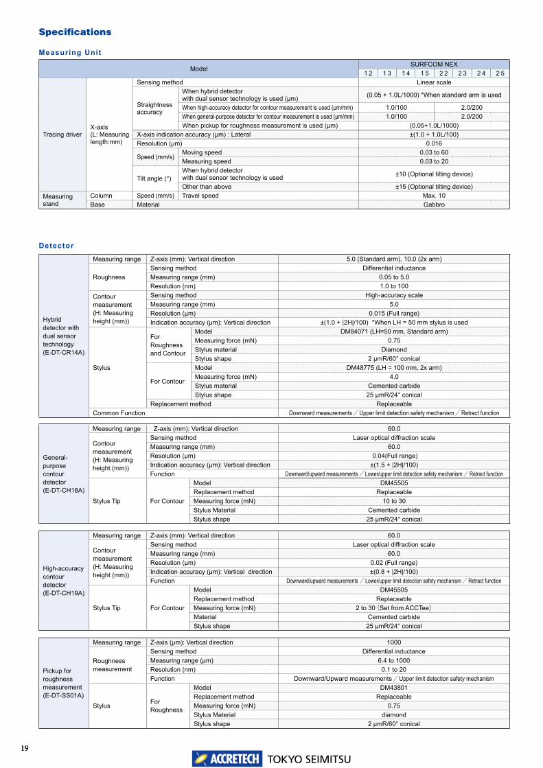
Specifications
Hybrid detector with dual sensor technology(E-DT-CR14A)
Measuring range Z-axis (mm): Vertical direction 5.0 (Standard arm), 10.0 (2x arm)
RoughnessSensing method Differential inductanceMeasuring range (mm) 0.05 to 5.0Resolution (nm) 1.0 to 100
Contour measurement(H: Measuring height (mm))
Sensing method High-accuracy scaleMeasuring range (mm) 5.0 Resolution (μm) 0.015 (Full range)Indication accuracy (μm): Vertical direction ±(1.0 + |2H|/100) *When LH = 50 mm stylus is used
Stylus
For Roughness and Contour
Model DM84071 (LH=50 mm, Standard arm)Measuring force (mN) 0.75Stylus material DiamondStylus shape 2 μmR/60° conical
For Contour
Model DM48775 (LH = 100 mm, 2x arm)Measuring force (mN) 4.0 Stylus material Cemented carbideStylus shape 25 μmR/24° conical
Replacement method ReplaceableCommon Function Downward measurements / Upper limit detection safety mechanism / Retract function
Detector
General-purpose contour detector(E-DT-CH18A)
Measuring range Z-axis (mm): Vertical direction 60.0
Contour measurement(H: Measuring height (mm))
Sensing method Laser optical diffraction scaleMeasuring range (mm) 60.0 Resolution (μm) 0.04(Full range)Indication accuracy (μm): Vertical direction ±(1.5 + |2H|/100)Function Downward/upward measurements / Lower/upper limit detection safety mechanism / Retract function
Stylus Tip For Contour
Model DM45505Replacement method ReplaceableMeasuring force (mN) 10 to 30Stylus Material Cemented carbideStylus shape 25 μmR/24° conical
High-accuracy contour detector(E-DT-CH19A)
Measuring range Z-axis (mm): Vertical direction 60.0
Contour measurement(H: Measuring height (mm))
Sensing method Laser optical diffraction scaleMeasuring range (mm) 60.0 Resolution (μm) 0.02 (Full range)Indication accuracy (μm): Vertical direction ±(0.8 + |2H|/100)Function Downward/upward measurements / Lower/upper limit detection safety mechanism / Retract function
Stylus Tip For Contour
Model DM45505Replacement method ReplaceableMeasuring force (mN) 2 to 30(Set from ACCTee)Material Cemented carbideStylus shape 25 μmR/24° conical
Pickup for roughness measurement (E-DT-SS01A)
Measuring range Z-axis (μm): Vertical direction 1000
Roughness measurement
Sensing method Differential inductanceMeasuring range (μm) 6.4 to 1000Resolution (nm) 0.1 to 20Function Downward/Upward measurements / Upper limit detection safety mechanism
Stylus For Roughness
Model DM43801Replacement method ReplaceableMeasuring force (mN) 0.75Stylus Material diamondStylus shape 2 μmR/60° conical
ModelSURFCOM NEX
1 2 1 3 1 4 1 5 2 2 2 3 2 4 2 5
Tracing driverX-axis(L: Measuring length:mm)
Sensing method Linear scale
Straightnessaccuracy
When hybrid detector with dual sensor technology is used (μm) (0.05 + 1.0L/1000) *When standard arm is used
When high-accuracy detector for contour measurement is used (μm/mm) 1.0/100 2.0/200When general-purpose detector for contour measurement is used (μm/mm) 1.0/100 2.0/200When pickup for roughness measurement is used (μm) (0.05+1.0L/1000)
X-axis indication accuracy (μm) : Lateral ±(1.0 + 1.0L/100) Resolution (μm) 0.016
Speed (mm/s)Moving speed 0.03 to 60Measuring speed 0.03 to 20
Tilt angle (°)When hybrid detector with dual sensor technology is used ±10 (Optional tilting device)
Other than above ±15 (Optional tilting device)Measuring stand
Column Speed (mm/s) Travel speed Max. 10Base Material Gabbro
Measuring Unit
TOKYO SEIMITSU20
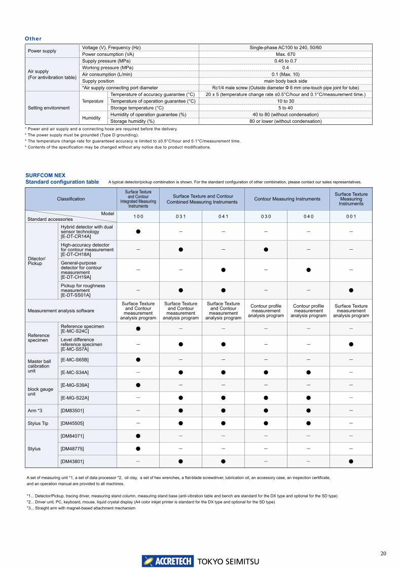
Other
Power supplyVoltage (V), Frequency (Hz) Single-phase AC100 to 240, 50/60Power consumption (VA) Max. 670
Air supply (For antivibration table)
Supply pressure (MPa) 0.45 to 0.7Working pressure (MPa) 0.4Air consumption (L/min) 0.1 (Max. 10)Supply position main body back side*Air supply connecting port diameter Rc1/4 male screw (Outside diameter Φ 6 mm one-touch pipe joint for tube)
Setting envitonmentTemperature
Temperature of accuracy guarantee (°C) 20 ± 5 (temperature change rate ±0.5°C/hour and 0.1°C/measurement time.)Temperature of operation guarantee (°C) 10 to 30Storage temperature (°C) 5 to 40
HumidityHumidity of operation guarantee (%) 40 to 80 (without condensation)Storage humidity (%) 80 or lower (without condensation)
* Power and air supply and a connecting hose are required before the delivery.* The power supply must be grounded (Type D grounding).* The temperature change rate for guaranteed accuracy is limited to ±0.5°C/hour and 0.1°C/measurement time.* Contents of the specification may be changed without any notice due to product modifications.
A set of measuring unit *1, a set of data processor *2, oil clay, a set of hex wrenches, a flat-blade screwdriver, lubrication oil, an accessory case, an inspection certificate, and an operation manual are provided to all machines.
*1... Detector/Pickup, tracing driver, measuring stand column, measuring stand base (anti-vibration table and bench are standard for the DX type and optional for the SD type)*2... Driver unit, PC, keyboard, mouse, liquid crystal display (A4 color inkjet printer is standard for the DX type and optional for the SD type)*3... Straight arm with magnet-based attachment mechanism
A typical detector/pickup combination is shown. For the standard configuration of other combination, please contact our sales representatives.SURFCOM NEX Standard configuration table
ClassificationSurface Texture
and Contour Integrated Measuring
Instruments
Surface Texture and Contour Combined Measuring Instruments Contour Measuring Instruments
Surface Texture Measuring
Instruments
Model 1 0 0 0 3 1 0 4 1 0 3 0 0 4 0 0 0 1
Ditector/ Pickup
Hybrid detector with dual sensor technology[E-DT-CR14A]
● - - - - -
High-accuracy detector for contour measurement[E-DT-CH18A]
- ● - ● - -
General-purpose detector for contour measurement[E-DT-CH19A]
- - ● - ● -
Pickup for roughness measurement[E-DT-SS01A]
- ● ● - - ●
Measurement analysis softwareSurface Texture
and Contour measurement
analysis program
Surface Texture and Contour
measurement analysis program
Surface Texture and Contour
measurement analysis program
Contour profile measurement
analysis program
Contour profile measurement
analysis program
Surface Texture measurement
analysis program
Referencespecimen
Reference specimen[E-MC-S24C] ● - - - - -
Level difference reference specimen[E-MC-S57A]
- ● ● - - ●
Master ballcalibration unit
[E-MC-S65B] ● - - - - -
[E-MC-S34A] - ● ● ● ● -
block gauge unit
[E-MG-S39A] ● - - - - -
[E-MG-S22A] - ● ● ● ● -
Arm *3 [DM83501] - ● ● ● ● -
Stylus Tip [DM45505] - ● ● ● ● -
Stylus
[DM84071] ● - - - - -
[DM48775] ● - - - - -
[DM43801] - ● ● - - ●
Standard accessories
TOKYO SEIMITSU21
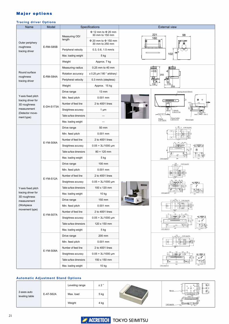
Name Model Specifications External view
Outer peripheryroughnesstracing driver
E-RM-S85B
Measuring OD/length
Φ 12 mm to Φ 20 mm30 mm to 150 mm
Φ 20 mm to Φ 150 mm30 mm to 250 mm
Peripheral velocity 0.3, 0.6, 1.5 mm/s
Max. loading weight 5 kg
Weight Approx. 7 kg
Round surfaceroughnesstracing driver
E-RM-S84A
Measuring radius 0.25 mm to 40 mm
Rotation accuracy ± 0.25 μm(180 ° arbitrary)
Peripheral velocity 0.3 mm/s (stepless)
Weight Approx. 15 kg
Y-axis fixed pitch tracing driver for 3D roughness measurement(Detector move-ment type)
E-DH-S173A
Drive range 13 mm
Min. feed pitch 0.001 mm
Number of feed line 2 to 4001 lines
Straightness accuracy 1 μm
Table surface dimensions ―
Max. loading weight ―
Y-axis fixed pitch tracing driver for 3D roughness measurement(Workpiece movement type)
E-YM-S06A
Drive range 50 mm
Min. feed pitch 0.001 mm
Number of feed line 2 to 4001 lines
Straightness accuracy 0.05 + 3L/1000 μm
Table surface dimensions 80 × 120 mm
Max. loading weight 5 kg
E-YM-S12A
Drive range 100 mm
Min. feed pitch 0.001 mm
Number of feed line 2 to 4001 lines
Straightness accuracy 0.05 + 3L/1000 μm
Table surface dimensions 100 x 120 mm
Max. loading weight 10 kg
E-YM-S07A
Drive range 150 mm
Min. feed pitch 0.001 mm
Number of feed line 2 to 4001 lines
Straightness accuracy 0.05 + 3L/1000 μm
Table surface dimensions 120 x 150 mm
Max. loading weight 5 kg
E-YM-S08A
Drive range 200 mm
Min. feed pitch 0.001 mm
Number of feed line 2 to 4001 lines
Straightness accuracy 0.05 + 3L/1000 μm
Table surface dimensions 150 x 150 mm
Max. loading weight 10 kg
2-axes auto leveling table
E-AT-S62A
Leveling range ± 2 °
Max. load 5 kg
Weight 4 kg
PickupE-DT-SS01A
Pickup holderE-DH-S151A
Y DRIVERE-DH-S173A
Tracing driver(100mm)
0
0
10
1 2 3 4
20 30 40 50 60 70 80 90 100 MILLIMETER
INCH
674036
Manual grip
(stroke 1/2)(stroke 1/2)4040
((10.510.5)) 145145
56.5
56.5
12.3
12.3
145145
6.56.56.56.5
1133
.233
.2
165165 45.545.535.535.5
8080 50.550.525252525
266266
195195
134
134
101
101
INCH
MILLIMETER50403020100
TRACING DRIVERMEASURING INSTRUMENT
SURFACE TEXTURE
1919858599
135135
105105
FEED
BACK
FORE
25252525
25252020
80805050
120
120
6-M4 depth8
3-M5 depth8
170170
100100 383850505050
150
150
273273
210210
1009080706050403020100
TRACING DRIVERMEASURING INSTRUMENTINCH
MILLIMETER
SURFACE TEXTURE
242242
FREE LOCKMANUAL SLIDE
10010025252525
120
120
25252525
252511
311
3
53533333
218.5218.5
8080 89897979100100
3-M5 depth10
9-M4 depth8
0
TRACING DRIVER
SURFACE TEXTUREMEASURING INSTRUMENTINCH
MILLIMETER90 100 110 120 130 140 15010 20 30 40 50 60 70 80
FEED
BACK
FORE
FREE CLAMP
262262 92.592.572.572.5
69.569.5150150 75757575
153
153
116
116
447447
302302
120
120
25252525
2525
1501505050 5050
24248080
1414153.5153.5
100100
177177
9-M4 depth8
3-M5 depth10
10 200 30 40 50 60 70 80 90 100 110 120 130 140 150 160 170 180 190 200
SURFACE TEXTUREMEASURING INSTRUMENT
TRACING DRIVER INCH
MILLIMETER
FREEMOTOR
YA
YB
MANUAL SLIDE
100100
150150 9090100100100100
150
150
113
113
530530
330330
150
1502525
25252525
1501505050 5050
41417676
193193173.9173.9
9-M4 depth8
3-M5 depth10
137.
413
7.4
150150
33
3333
33
26.2
26.2
36.2
36.2
7575
199.9199.9 8.28.241.741.7 150150
5757 6161
79.279.2 7575 45.745.7
3333
505013
.713
.712
012
0
5050 5050
4848
3-Ø3-Ø12123-M3 depth6
Major opt ions
Tracing driver Options
Automatic Adjustment Stand Options
TOKYO SEIMITSU22
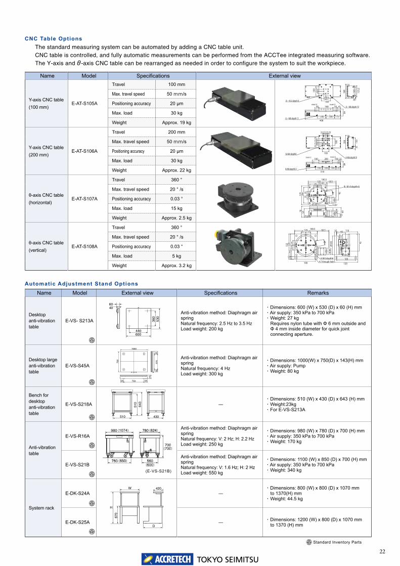
Name Model Specifications External view
Y-axis CNC table (100 mm)
E-AT-S105A
Travel 100 mm
Max. travel speed 50 mm/s
Positioning accuracy 20 μm
Max. load 30 kg
Weight Approx. 19 kg
Y-axis CNC table (200 mm)
E-AT-S106A
Travel 200 mm
Max. travel speed 50 mm/s
Positioning accuracy 20 μm
Max. load 30 kg
Weight Approx. 22 kg
θ-axis CNC table (horizontal)
E-AT-S107A
Travel 360 °
Max. travel speed 20 ° /s
Positioning accuracy 0.03 °
Max. load 15 kg
Weight Approx. 2.5 kg
θ-axis CNC table (vertical)
E-AT-S108A
Travel 360 °
Max. travel speed 20 ° /s
Positioning accuracy 0.03 °
Max. load 5 kg
Weight Approx. 3.2 kg
8-M4 depth 8
4-M6 depth 10stroke1/2stroke1/2
6-M6 depth 12
25252525
2525252510
010
0
100100
408408
7171
4141
8484
100100100100
50501601605050
3030
125.
212
5.2
100
100
160
160
4-M6 depth1016-M4 depth8
25252525
25252525
100
100
2525252525252525
100100
Stroke1/2
8-M6 depth12
Stroke1/2
7272
2222
8484
510510
100100100100100100
100100100100 200200
353513
013
0
200
200
8-M4depth6
240270300
Ø16Ø16
4-4-Ø7Ø7
100100
100
100 92 92
120
120 25 25
2525
180.5180.560.560.5120120
25252525
6060ØØ3636
2222
7070 54 5488
ØØ100100
4-M4 depth64-7 through-hole
210
100100
25252525
72 7212
012
013
213
212 12
2525 2525120120 60.560.5180.5180.5
ØØ3636
9292
120120
100100
ØØ10
010
0
48481010 110110
Name Model External view Specifications Remarks
Desktopanti-vibrationtable
E-VS- S213A
Anti-vibration method: Diaphragm air springNatural frequency: 2.5 Hz to 3.5 HzLoad weight: 200 kg
・ Dimensions: 600 (W) x 530 (D) x 60 (H) mm・ Air supply: 350 kPa to 700 kPa・ Weight: 27 kg
Requires nylon tube with Φ 6 mm outside andΦ 4 mm inside diameter for quick jointconnecting aperture.
Desktop largeanti-vibration table
E-VS-S45A
Anti-vibration method: Diaphragm air springNatural frequency: 4 Hz Load weight: 300 kg
・ Dimensions: 1000(W) x 750(D) x 143(H) mm・ Air supply: Pump・ Weight: 80 kg
Bench for desktopanti-vibration table
E-VS-S218A ―・ Dimensions: 510 (W) x 430 (D) x 643 (H) mm ・ Weight:23kg ・ For E-VS-S213A
Anti-vibrationtable
E-VS-R16A
Anti-vibration method: Diaphragm air springNatural frequency: V: 2 Hz; H: 2.2 HzLoad weight: 250 kg
・ Dimensions: 980 (W) x 780 (D) x 700 (H) mm・ Air supply: 350 kPa to 700 kPa・ Weight: 170 kg
E-VS-S21B
Anti-vibration method: Diaphragm air springNatural frequency: V: 1.6 Hz; H: 2 HzLoad weight: 550 kg
・ Dimensions: 1100 (W) x 850 (D) x 700 (H) mm・ Air supply: 350 kPa to 700 kPa・ Weight: 340 kg
System rack
E-DK-S24A ―・ Dimensions: 800 (W) x 800 (D) x 1070 mm
to 1370(H) mm・ Weight: 44.5 kg
E-DK-S25A ― ・ Dimensions: 1200 (W) x 800 (D) x 1070 mmto 1370 (H) mm
The standard measuring system can be automated by adding a CNC table unit. CNC table is controlled, and fully automatic measurements can be performed from the ACCTee integrated measuring software. The Y-axis and θ-axis CNC table can be rearranged as needed in order to configure the system to suit the workpiece.
CNC Table Options
Automatic Adjustment Stand Options
Standard Inventory Parts
(E-VS-S21B)

TOKYO SEIMITSU23
SURFCOM NEX *** DX/SD - ○○
ItemDetector/Pickup
Model(Commodity
code)
Remarks
Hybrid detector with dual sensor technology
For Contour measurement Pickup for roughness measurement
* Three digit code shows the followings.
Third digit (hundreds place): Presence or absence of hybrid detector0 = Hybrid detector is not provided1 = Hybrid detector is provided
Second digit (tens place): Presence or absence of detector for contour measurement0 = Contour detector is not provided3 = Contour detector (general-purpose) is provided4 = Contour detector (high-accuracy) is provided
First digit (ones place): Presence or absence of detector for roughness measurement0 = Roughness detector is not provided1 = Roughness detector is provided
General-purpose detector High-accuracy detectorModel E-DT-CR14A E-DT-CH18A E-DT-CH19A E-DT-SS01A
External View
Model name
1 0 0 ● - - - K2 △□ 100
1 3 0 ● ● - - K2 △□ 130
1 4 0 ● - ● - K2 △□ 140
1 0 1 ● - - ● K2 △□ 101
1 3 1 ● ● - ● K2 △□ 131
1 4 1 ● - ● ● K2 △□ 141
0 3 0 - ● - - K2 △□ 030
0 4 0 - - ● - K2 △□ 040
0 0 1 - - - ● K2 △□ 001
0 3 1 - ● - ● K2 △□ 031
0 4 1 - - ● ● K2 △□ 041
Detector selection
Type selection
Item Type
Model(Commodity code)
DX SD
External View
SpecificationsDestination Japan Overseas Japan Overseas
Computer Included Included Not included Included Included Not included
Model name
D X
● - - - - - K2 A□***
- ● - - - - K2 B□***
- - ● - - - K2 C□***
S D
- - - ● - - K2 D□***
- - - - ● - K2 E□***
- - - - - ● K2 F□***
Product name
Detector Type Tracing driver and measuring stand
Type naming convention based on the system configuration and selection
24TOKYO SEIMITSU
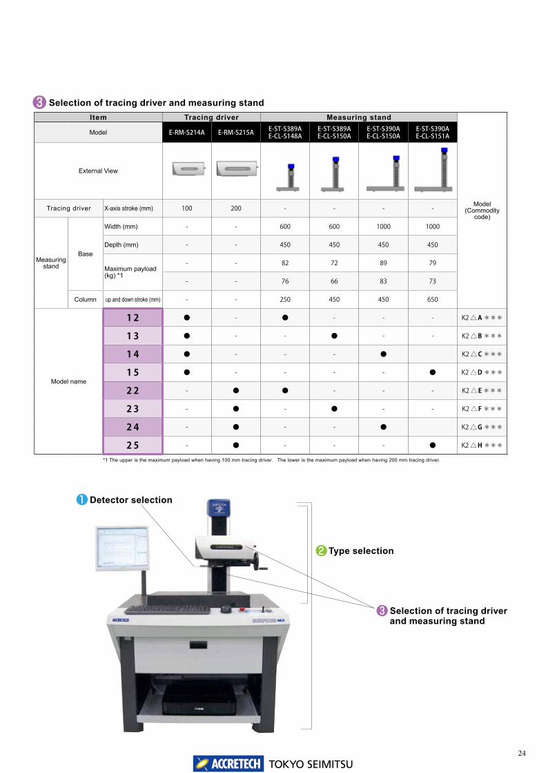
Selection of tracing driver and measuring standItem Tracing driver Measuring stand
Model(Commodity
code)
Model E-RM-S214A E-RM-S215A E-ST-S389AE-CL-S148A
E-ST-S389AE-CL-S150A
E-ST-S390AE-CL-S150A
E-ST-S390AE-CL-S151A
External View
Tracing driver X-axis stroke (mm) 100 200 - - - -
Measuring stand
Base
Width (mm) - - 600 600 1000 1000
Depth (mm) - - 450 450 450 450
Maximum payload (kg) *1
- - 82 72 89 79
- - 76 66 83 73
Column up and down stroke (mm) - - 250 450 450 650
Model name
1 2 ● - ● - - - K2 △A ***
1 3 ● - - ● - - K2 △B ***
1 4 ● - - - ● K2 △C ***
1 5 ● - - - - ● K2 △D ***
2 2 - ● ● - - - K2 △E ***
2 3 - ● - ● - - K2 △F ***
2 4 - ● - - ● K2 △G ***
2 5 - ● - - - ● K2 △H ***
*1 The upper is the maximum payload when having 100 mm tracing driver. The lower is the maximum payload when having 200 mm tracing driver.
Detector selection
Type selection
Selection of tracing driver and measuring stand

25TOKYO SEIMITSU
Service station
Service stationTosei Engineering Corp.
Head Office & Service network
Head Office2968-2, Ishikawa-machi, Hachioji-shi, Tokyo, 192-8515 JapanTel: +81 (0) 42-642-1701 Fax: +81 (0) 42-642-1821
Tsuchiura Plant4, Higashi-Nakanuki-cho, Tsuchiura-shi, Ibaraki, 300-0006 JapanTel: +81 (0) 29-831-1234 Fax: +81 (0) 29-831-4453
Tohoku OfficeRoyal Hills Kawara-cho, 2-6-22, Kawahara-cho, Wakabayashi-ku, Sendai-shi, Miyagi, 984-0816 JapanTel: +81 (0) 22-224-0121 Fax: +81 (0) 22-224-7083
Kita-kanto Office4, Higashi-Nakanuki-cho, Tsuchiura-shi, Ibaraki, 300-0006 Japan (Tokyo Seimitsu Tsuchiura Plant)Tel: +81 (0) 29-831-6801 Fax: +81 (0) 29-831-6808
Saitama OfficeMJ Akashiba Bldg. 8F, 1-497, Higashionari-cho, Kita-ku, Saitama-shi, Saitama, 331-0814 JapanTel: +81 (0) 48-667-8583 Fax: +81 (0) 48-667-8578
Tokyo Office2968-2, Ishikawa-machi, Hachioji-shi, Tokyo (Tokyo Seimitsu Hachioji Plant), 192-0032 JapanTel: +81 (0) 42-642-0186 Fax: +81 (0) 42-642-0385
Atsugi OfficeGent Bldg., 4-11-26, Asahi-cho, Atsugi-shi, Kanagawa, 243-0014 JapanTel: +81 (0) 46-229-7031 Fax: +81 (0) 46-229-7033
Nagano OfficeOTK Bldg. 1F, 2-8-6, fukashi, matsumoto, Nagano, 390-0815 JapanTel: +81 (0) 263-33-2004 Fax: +81 (0) 263-44-7771
Niigata Office1-1-74, Bunsui-cho Akebomo, Tsubame-shi, Niigata, 959-0132 JapanTel: +81 (0) 256-97-4665 Fax: +81 (0) 256-97-1773
Hamamatsu OfficeHigashiyama 6 Bldg., 7-5, Hososhima-cho, Naka-ku, Hamamatsu-shi, Shizuoka , 435-0045 JapanTel: +81 (0) 53-460-7131 Fax: +81 (0) 53-460-7132
Nagoya Office96, Shin-Ikeura, Uchikoshi-cho, Miyoshi-Shi, Aichi, 470-0213 JapanTel: +81 (0) 561-32-8501 Fax: +81(0) 561-32-8618
Hokuriku OfficeWindSquare. room 101, 31-1, Nakagawara, Toyama-shi, Toyama, 939-8015 JapanTel: +81 (0) 76-422-6755 Fax: +81 (0) 76-422-6757
Osaka Office1-18-27, Esaka-cho, Suita-shi, Osaka, 564-0063 JapanTel: +81 (0) 6-6821-0221 Fax: +81 (0) 6-6821-0210
Himeji OfficeNagai Bldg., 201, 385, Miyano-machi, Hojyo, Himeji-shi, Hyogo, 670-0948 JapanTel: +81 (0) 79-222-5480 Fax: +81 (0) 79-222-5489
Hiroshima OfficeCharmant Tsuji, 1-10-18, Yokokawa-cho, Nishi-ku, Hiroshima-shi, Hiroshima, 733-0011 JapanTel: +81 (0) 82-293-5660 Fax: +81 (0) 82-292-2218
Kyusyu OfficeKyuudenfudosan 5F, 1-13-8, Yakuin, Chuo-ku, Fukuoka-shi, Fukuoka, 810-0022 JapanTel: +81 (0) 92-737-1821 Fax: +81 (0) 92-737-1822
Head Office4-6, Higashi-Nakanuki-cho, Tsuchiura-shi, Ibaraki, 300-0006 JapanTel: +81 (0) 29-830-1888 Fax: +81 (0) 29-830-1881
Tsuchiura Kandatsu Plant2-14, Kita-Kandatsu-cho, Tsuchiura-shi, Ibaraki, 300-0015 JapanTel: +81 (0) 29-830-1882 Fax: +81(0) 29-832-5742
Tohoku OfficeSudo Bldg., 3-20, Nishiki-cho, Yamagata-shi, Yamagata, 990-0056 JapanTel: +81 (0) 23-625-3957 Fax: +81 (0) 29-832-4053
Ota Office454-2, Komaki-cho, Ota-shi, Gunma, 373-0818 JapanTel: +81 (0) 276-48-5221 Fax: +81 (0) 29-832-4053
Saitama OfficeMJ Akashiba Bldg. 8F, 1-497, Higashionari-cho, Kita-ku, Saitama-shi, Saitama, 331-0814 JapanTel: +81 (0) 48-669-0055 Fax: +81 (0) 29-832-4053
Tokyo Office2968-2, Ishikawa-machi, Hachioji-shi, Tokyo, (Tokyo Seimitsu Hachioji Plant), 192-0032 JapanTel: +81 (0) 42-631-9757 Fax: +81 (0) 29-832-4053
Atsugi OfficeGent Bldg., 4-11-26, Asahi-cho, Atsugi-shi, Kanagawa, 243-0014 JapanTel: +81 (0) 46-229-2448 Fax: +81 (0) 29-832-4053
Nagano OfficeOTK Bldg. 1F, 2-8-6, fukashi, matsumoto, Nagano, 390-0815 JapanTel: +81 (0) 263-33-2004 Fax: +81 (0) 263-44-7771
Hamamatsu OfficeHigashiyama 6 Bldg. 1F, 7-5, Hososhima-cho, Naka-ku, Hamamatsu-shi, Shizuoka , 435-0045 JapanTel: +81 (0) 53-460-9260 Fax: +81 (0) 29-832-4053
Nagoya Office96, Shin-Ikeura, Uchikoshi-cho, Miyoshi-City, Aichi, 470-0213 JapanTel: +81 (0) 561-32-3601 Fax: +81 (0) 29-832-4053
Hokuriku OfficeWindSquare. room 101, 31-1, Nakagawara, Toyama-shi, Toyama, 939-8015 JapanTel: +81(0) 76-422-6401 Fax: +81 (0) 29-832-4053
Osaka Office1-18-27, Esaka-cho, Suita-shi, Osaka, 564-0063 JapanTel: +81 (0) 6-6821-0231 Fax: +81 (0) 29-832-4053
Hiroshima OfficeCharmant Tsuji, 1-10-18, Yokokawa-cho, Nishi-ku, Hiroshima-shi, Hiroshima, 733-0011 JapanTel: +81 (0) 82-291-8501 Fax: +81 (0) 29-832-4053
Fukuoka OfficeKyuudenfudosan 5F, 1-13-8, Yakuin, Chuo-ku, Fukuoka-shi, Fukuoka, 810-0022 JapanTel: +81 (0) 92-713-2155 Fax: +81 (0) 29-832-4053
Kyusyu OfficeMasunaga Bldg., 3-3-25, Suizenji, Chuo-ku, Kumamoto-shi, Kumamoto, 862-0950 JapanTel: +81 (0) 96-383-2788 Fax: +81 (0) 29-832-4053
Parts Center Fax: 0120-995-611
Call Center Tel: 0120-995-633

26TOKYO SEIMITSU
World wide Sales and Service Offices
Overseas Sales Group (JAPAN)4, Higashi-Nakanuki-machi,Tsuchiura-shi, Ibaraki 300-0006, JapanTel: +81 (0) 29-831-1240Fax: +81 (0) 29-831-1461
USACarl Zeiss Industrial Metrology, LLC6520 Sycamore Ln Maple Grove MNTel: +1-763-744-2400
Technical Center: Maple Grove MN, Brighton MI, West Coast CA
Satellite offices/Application center (BP) : Houston TX, Dallas TX, Loudon TN, Charlotte, NC, Boston MA, Chicago IL, Irvin CA, Oakville Ontario (Canada)
MexicoCarl Zeiss de Mexico S.A. de C.V.Av. Miguel Angel de Quevedo 496Santa Catarina Ciudad de Mexico, Destrito FederalTel: +52-55-5999-0200
Satellite Offices/Application center (BP) : Queretaro, Silao, Monterrey
GermanyAccretech (Europe) GmbH(Head Office)Landsberger Str. 396, D-81241 Munich, GermanyTel: +49 (0) 89-546788-0Fax: +49 (0) 89-546788-10
(Dresden Office)Hugo-Junkers-Ring 9, D-01109 Dresden, GermanyTel: +49(0)351-89024-11Fax: +49(0)351-89024-12
BrazilAccretech do Brasil Ltda.77 Room, 7th Floor, Rua Nove de Julho 72 Santo Amaro, Sao Paulo 04739-010, BrazilTel: +55(0)11-3360-9531Fax: +55(0)11-3360-9531
ChinaAccretech (China) Co., Ltd.(Head Office/Shanghai)Room2101C, No.1077 ZuChongZhi Road, Zhang Jiang Hi-Tech Park, Pudong New Area, Shanghai, China, 201203Tel: +86 (0) 21-3887-0801Fax: +86 (0) 21-3887-0805
(Shanghai Office) Ground floor, No.118 Fu Te Bei Road, Pudong New Area, Shanghai, China, 200131Tel: +86 (0) 21-5064-0258Fax: +86 (0) 21-5064-0356
(Beijing Office) Room 404, Building 1#, China Supply And Marketing Foreign Trade Building, No.1 Shui An South Street. Chaoyang District, Beijing, China, 100012Tel: +86 (0) 10-8490-4771Fax: +86 (0) 10-8447-7010
(Tianjin Office) Room 606, Brilliant Crystal Tower, 53-1 Weidi Road, Hexi District, Tianjin, China, 300201Tel: +86 (0) 22-8822-7220Fax: +86 (0) 22-2833-2125
(Changchun Office) Room 1905, Unit 1, No.1, Huayihongfu, Hong Qi Street, Changchun, Jilin, Province China, 130021Tel: +86 (0) 431-8896-1051Fax: +86 (0) 431-8896-0661
(Dalian Office:) Room 715, Building 3#, Yifeng Modern City, Jin Ma Road, Development Zone, DaLian City, Liaoning Province, China, 116000Tel: +86 (0) 411-8756-5414Fax: +86 (0) 411-8756-5414
(Shenzhen Office) Room 1507, Tianliao Tower, No.A Tianliao Industrial Park, Shenzhen, Guangdong Province, China, 518055Tel: +86 (0) 755-2515-9842Fax: +86 (0) 755-2515-7737
(Guangzhou Office) Room 1903, Building 1, Jin Xiu Hua Ting, No.12 Guang Ming Bei Road, Panyu District, Guangzhou, Guangdong Provincee, China, 511400Tel: +86 (0) 20-3887-0975Fax: +86 (0) 20-3887-0627
(Chongqing Office) 21F-A3, Chongqing Lanko Hyatt Building, No.2 Nanping West Road, Nanan District, Chongqing, China, 400060Tel: +86 (0) 23-6295-5061Fax: +86 (0) 23-6295-5060
(Chengdu Office) 2-1-1405 Qingjiangyaju, No.122 East Qingjiang Road Qingyang District, Chengdu, China, 610072Tel: +86 (0) 28-8738-2279Fax: +86 (0) 28-8738-2279
(Suzhou Office) Room302, No.72 Youngor Future Garden, No.588 Shenhu Street, Suzhou Industrial Park, Jiangsu Province, China, 215027Tel: +86 (0) 512-6265-6436Fax: +86 (0) 512-6265-6435
(Wuxi Office) Room 7-407, No12, Changjiang Road, Wuxi, Jiangsu Province, China, 214028Tel: +86 (0) 510-8101-7346Fax: +86 (0) 510-8101-7346
(Nanjing Office) Room 602, Buiding 4, Tongxi International Plaza, No.1222, Shuanglong Avenue Jiangning Area, Nanjing, Jiangsu Province, China, 211100Tel: +86 (0) 25-5867-9932Fax: +86 (0) 25-5867-9931
(Ningbo Office) Room 902, No.151, Cangsong Road, Haishu District, Zhejiang Province, China, 315000Tel: +86 (0) 574-8772-7550Fax: +86 (0) 574-8772-7660
(Jinan Office) Room 15B08, Building 2# ,Ginza Plaza, No.66 East Shunhe Road, Jinan City, Shandong Province, China, 250002Tel: +86 (0) 531-6668-8196Fax: +86 (0) 531-6668-8190
(Wuhan Office) Room 2410, Unit 2, Buiding 8, Fuxinghuiyu International City, No.28, Xudong road, Wuchang District, Wuhan, Hubei Province, China, 430062Tel: +86 (0) 27-8665-9291Fax: +86 (0) 27-8665-9293
Accretech (Pinghu) Co., Ltd.Building 2#, No 1389, Xinqun Road, Pinghu Economic Development Zone, Pinghu City, Zhejiang, PRC. China, 314200Tel: +86 (0) 573-8520-8060Fax: +86 (0) 573-8520-8065
KoreaAccretech Korea Co., Ltd. (Head Office/Seongnam)(3F, Fine Venture Bldg., Yatap-dong) 41, Seongnam-daero 925 beon-gil, Bundang-gu,Seongnam-si, Gyeonggi-do, 463-828, KoreaTel: +82 (0) 31-786-4000 Fax: +82 (0) 31-786-4090
(Ulsan Office)(1F 841-8, Myeongchon-dong)30, Myeongchon 7-gil, Buk-gu, Ulsan, 683-390, KoreaTel: +82 (0) 52-268-2136Fax: +82 (0) 52-268-2137
TaiwanAccretech (Taiwan) Co., Ltd. (Metrology Division)2F., No.199, Zhonghe St., Zhubei City,Hsinchu County 30267, Taiwan (R.O.C)Tel: +886 (0) 3-553-1300Fax: +886 (0) 3-553-1319
ThailandTokyo Seimitsu (Thailand) Co., Ltd. (Metrology Division)2/3 Moo 14, Bangna Tower B, 1st Fl., Bangna-Trad Road. K.M. 6.5, Bangkaew, Bangplee, Samutprakarn 10540 ThailandTel: +66 (2) 751-9573, 9574Fax: +66 (2) 751-9575
VietnamAccretech Vietnam Co., Ltd.(Head Office/Hanoi)356 room, 6thFloor, Office Building, 85 Nguyen Du St, Hai Ba Trung Dist, Hanoi, VietnamTel: +84 (4) 3941-3309Fax: +84 (4) 3941-3310
(Ho Chi Minh Office)Room No.1101-1102, the 11th Floor, Broadcard Office Building, 343 Dien Bien Phu Street, Ward, 15, Binh Thanh District, Ho Chi Minh City, VietnamTel: +84 (8) 3512-6760Fax: +84 (4) 3941-3310
Indonesia PT Accretech IndonesiaKomplek Rukan Cikarang Square Block D No.68 JL. Raya Cikarang-Cibarusah KM 40 No.1 Cikarang Bekasi 17530, IndonesiaTel: +62 (0) 21-2961-2375Fax: +62 (0) 21-2961 2376
IndiaCarl Zeiss India (Bangalore) Pvt. Ltd.Plot No.3, Jigani Link Road, Bommasandra Industrial Area Bangalore 560 099, IndiaTel: +91(0)80-4343-8000
(New Delhi)DSM 349, 350 & 351, 3rd Floor, #15, DLF Tower, Shivaji Marg New Delhi 110 015, IndiaTel: +91(0)11-4515-6000
(Chennai)New No.119/5, 2nd Floor, Dr.Radhakrishna Salai, Opp. Savera Hotel, Mylapore, Chennai 600 004, IndiaTel: +91(0)44-2811-2600
(Pune)101, Akruti Avenues 17/1/2, Wakad Thergaon Road Wakad Pune 411 057, IndiaTel: +91(0)20-6511-0600

B-83-701-E-1506ISO 9001 and ISO 14001 awarded to the Hachioji and Tsuchiura Plants
We reserve the right to change the contents of this catalog, including product specifications, without notice when products are updated.
h t t p : / / w w w . a c c r e t e c h . j p /
Some of our products shall be controlled by the Foreign Exchange and Foreign Trade Act, and required an export license by the Japanese Government.Regarding exporting the products and/or providing a non-resident with technologies, please consult ACCRETECH(Tokyo Seimitsu).
TOKYO SEIMITSU