Embed Size (px)
Citation preview

1 National Museum of Nature and Science Vol.16,2011
Systematic Review of Tyre Technology
Yasuhiro Ishikawa
■ Abstract
The history of the tyre starts with the use of the wheel, using a log or its x-section. Tyres then came
into common use on the wheels of carts or horse carts. The pneumatic tyre was originally invented
by R.W. Thomson in the middle of 19th century. Then at the end of 19th century, a pneumatic tyre
for automobiles was invented. The history of the Japanese rubber industry also starts around this
time: the latter half of 19th century, out of which the tyre industry then developed. The history of the
Japanese tyre industry is divided into the three following stages:
Stage 1: Dawn of the Industry
The Japanese tyre industry began in the Meiji era (1868-1912) with the initial development of the
Japanese rubber industry. The foundation of Tsuchiya Rubber Factory in 1886 (Meiji 19) is generally
taken to herald the start of the Japanese rubber industry, approximately fifty years after the invention
of vulcanization by C. Goodyear in 1839.
Stage 2: Age of Growth
This period from the beginning of the Taisho era (1912-1926) to the end of World War II saw the
introduction to Japan of rubber technology from foreign countries, when domestic industry as a
whole was developing with the importation of various technologies. The founding of domestic tyre
manufacture dates from this period. Domestically-developed tyre technology showed dramatic
growth during the War and played an important role in military supplies.
Stage 3: Maturity
This stage covers the time from the end of the War II to the present. Although tyre manufacturing
suffered significant damaged during the War, recovery was rapid, and tyre technology saw further
dramatic development with the growth of motorisation. This period of growing post-War
motorisation is divided into three parts.
The first period was when new materials such as nylon and synthetic rubber were developed. In this
period, processing technology that could deal with these new raw materials was developed for the
tyre.
The second period saw tyre construction completely change from bias to radial tyres. This
significant development in tyre construction saw not only major changes in materials, such as the use
of steel cord, but also in the modification of production equipment.
In the third period, the various elemental technologies were integrated, resulting in the further
refinement of the steel radial tyre and the achievement of its durability in terms of adhesion between
1

2 National Museum of Nature and Science Vol.16,2011
the rubber and steel cords, and preventing rubber fatigue throughout the tyre’s working life.
Following this period, better motion performance was required of tyres. However, it was well known
that a tyre with lower rolling resistance had the problem of lower skid resistance. This performance
trade-off is still major issue with tyres today. In addition, the improvement of ride quality, such as
the reduction of noise and vibration, came to be increasingly important in tyre performance.
Therefore, more exacting demands have been made of tyre performance since the 1980s.
Many epoch-making technologies have been developed since the War in the areas of raw materials
and construction, and which have then been incorporated into tyre technology. How much Japan has
contributed to these developments in tyre technology is debatable; however, Japanese tyre
technology has recently been earning itself recognition in the tyre industry by further consolidating
these technologies. The next decade will see rising demand for environmentally friendly solutions,
spurring the need for new technology that addresses this major issue.
■Profile Yasuhiro Ishikawa Chief Survey Officer, Center of the History of Japanese Industrial Technology, National Museum of Nature and Science March 1969 Completed Master’s degree at Tokyo
Institute of Technology Graduate School of Engineering
April 1969 Employed in the laboratory at Yokohama Rubber Company
October 1993 Head of the Tire Materials Development Department, Yokohama Rubber Company
July 1996 Director of the Tire Materials
Development Laboratory, Yokohama Rubber Company
July 2001 Director, Yokohama Rubber Company July 2003 Chief Engineer, Yokohama Rubber
Company July 2005 Consultant, Yokohama Rubber
Company January 2008 Retired 2001-2002 Vice President, The Society of Rubber
Science and Technology, Japan Present Chairperson, Moulded Processing
Technology Subcommittee, Research Committee, The Society of Rubber Science and Technology, Japan
Doctor of Engineering
■Contents
1. Introduction
2. Creation of the Tyre
3. Dawn of the Japanese Rubber Industry (The Age of
Early Compounding Techniques)
4. Stage of Growth: Creation of the Domestic Tyre
Industry
5. Stage of Maturity: The Age of Motorisation
6. The Coming of Age of Radial Tyres
7. Detailed Description of Tyres Requiring Additional
Performance
8. Summary of Technology Progress
List of Candidates for Registration
3 National Museum of Nature and Science Vol.16,2011
1. Introduction
1.1. Outline of Tyre Technology
Tyres are an essential component to the
establishment of the automobile mechanism.
Tyres can be viewed as having the following
four functions 1)).
- Bearing a load (support)
- Acting as a spring (absorption)
- Conveying driving and braking forces
(transmission)
- Facilitating steering of the vehicle (turning)
These are vital functions in which the tyres as
part of the vehicle serve as an intermediary in
establishing a mutual relationship between the
vehicle and the surface of the road.
The history of tyre technology is the history of
developments carried out to achieve these
functions. This technology is expansive in
extent, combining many materials to form the
mechanics of the tyre, which in turn plays a
complex role being incorporated as a
component into the automobile mechanism.
Thus, tyre technology is expansive and has
come to hold an important place in the industry.
Tyres are a rubber product. Rubber technology
had a long history before the invention of the
tyre in the 19th century. The technology
followed the same path in Japan, albeit later.
1.2. Progress of Japanese Tyre
Technology (Systematisation) (See Fig. 1.1)
The history of the tyre industry in Japan
can be divided into three stages.
Stage 1: Dawn of the Industry – Meiji Period.
The dawn of the Japanese rubber industry saw
some rudimentary developments.
Stage 2: Stage of Growth – Early Taisho Period
to the Second World War. From the Taisho
Period to the early Showa Period, Japan either
introduced overseas technology or started
developing its own independent technology.
This technology later played a role as military
goods during wartime.
Stage 3: Stage of Maturity – Post-War to the
present. While various companies suffered
during the war, they bounced back from the
ravages of war and, accompanied by the later
spread of motorisation, grew rapidly to the
present day 2).
The Stage 3 post-war age of motorisation can
be divided into three further stages.
The first stage was the age of incorporating
new materials into the existing bias tyres.
Instead of cotton or rayon for reinforcing,
synthetic nylon appeared; synthetic rubbers
such as SBR (styrene-butadiene rubber) and BR
(butadiene rubber) also appeared as a
replacement for natural rubber. This stage is
remembered as an age in which new materials
appeared and much effort was spent on
processing techniques in order to fully utilise
them (post-war – 1960s)

4 National Museum of Nature and Science Vol.16,2011
Fig. 1.1. Progress of Japanese Tyre Technology (Systematisation)
The second stage was the age in which tyre
structure changed from bias to radial. This
major change in tyre structure was
accompanied by major changes in
manufacturing facilities. The appearance of
steel cord reinforcing meant major changes in
tyre structure and manufacturing facilities,
accompanied by major progress in tyre
performance.
The third stage is the age of integrating various
elements of existing technology and improving
radial tyre performance. This stage can be
divided into a further four stages.
The first was the age of perfecting radial tyre
durability. This was an age of ensuring
durability, fraught with issues such as how to
fasten steel cord and rubber together and
dealing with separation due to breakdown in
the rubber. 1970s-1980s.
The second was the age of ensuring high
manoeuvrability as a required performance
over and above durability. This was affected
by the 1979 oil crisis, with a rapidly-increasing
demand for improved fuel economy. This
presented some issues with safety, since tyres
with good fuel economy moved easily but
were difficult to stop. Competition soared
around the world to resolve this paradox.
1980s onwards.
The third was the age of increased sensation
Part 1 (Tyre Outline) Chapter 1: Introduction, Chapter 2: Creation of the Tyre
Part 2 (Progress of Japanese Tyre Technology) (1)
Chapter 3: The Start of the Japanese Rubber Industry
– End of the Meiji Period (Dawn)
(2)Chapter 4: Creation of the
Japanese Tyre Industry Taisho Period, Early Showa
Period, End of the War
(3) Chapter 5: Post-War Developments
Post-War – (Stage of Maturity; Age of
Motorisation) (Stage of Growth; Technology Imports; Domestic
Production Period)
Chapter 5 The Age of Motorisation
Stage 1The Age of New
Materials (Use of Nylon,
Synthetic Rubber)
Stage 2The Age of
Structural Change(Bias → Radial)
(Use of Steel Cord, Polyester)
Stage 3 The Age of Radial
Tyres (The Age of Evolution)
Chapter 6
Chapter 6 The Coming of Age of Radial Tyres;
The Age of Evolution Stage 1
Durability (Change of Materials)
Stage 2 Manoeuvrability
(Change of Materials/Structure)
Stage 3 Sensation and
Sensitivity (Change of Structure) Stage 4: Integration
Chapter 7 Additional PerformanceAircraft; Construction Vehicles; Two-Wheeled Vehicles; Studless
Introductory Stage
Stage of Growth
Stage of Maturity
Systematisation Trends

5 National Museum of Nature and Science Vol.16,2011
and sensitivity, such as noise and vibration.
1980s onwards.
The fourth was the coming of age of tyre
performance. There was a demand for a high
degree of all-round perfection, with high levels
of durability and manoeuvrability as well as
sensation and sensitivity factors such as noise
and vibration taken care of. In other words, it
was an age of demand for perfection in all
component technologies in all areas of
performance and of theories developed to that
end.
Other tyres (such as aircraft tyres, tyres for
construction vehicles, tyres for two-wheeled
vehicles and studless tyres) require
additional performance capabilities than
normal. These have played a role in
presenting tyre technology with the challenges
of additional performance (such as heat
resistance and friction on ice).
Broadly, the progress of post-war technology
development has alternated between material
(nylon and synthetic rubber), structural (radial
tyres), material (rolling resistance due to radial
material durability and variety of SBR) and
structural (sensation, sensitivity, noise,
vibration, ride comfort). At each stage, the
most suitable techniques have been eagerly
sought out and surpassed.
Fig 1.2. Current Types of Tyres 3)Gomu / Erasutomā to Mirai no Kōtsū [Rubbers / Elastomers and
Future Transportation] Rubber Technology Forum, ed., Gomutimes, March 2010, p
Side ReinforcingRubber
High-Performance Passenger Vehicle Tyre
Fuel-Efficient Tyre Studless Tyre Run-Flat Tyre
Racing Tyre ConstructionVehicle Tyre Truck/Bus Tyre Aircraft Tyre
6 National Museum of Nature and Science Vol.16,2011
Fig. 1.3. Tyre Structure (Radial Tyre)
(Cross-Section)
Looking back through this history of
development, there are very few major
breakthroughs in which Japan actively
contributed to epoch-making technology, such
as the change from bias tyres to radial tyres, or
the appearance of synthetic rubber or steel
cords. However, Japan’s later presence in the
tyre industry has been unwavering; ultimately,
its strength in the industry – its operational
strength combined with its technological
strength (optimisation strength) – is significant.
This is probably due to the significant presence
of its technological strength based on
manufacturing. It is also probably a
combination of the Japanese-style technology
prioritisation (diligent manufacturing for
optimisation rather than major innovation) and
the emphasis on companies (enterprises).
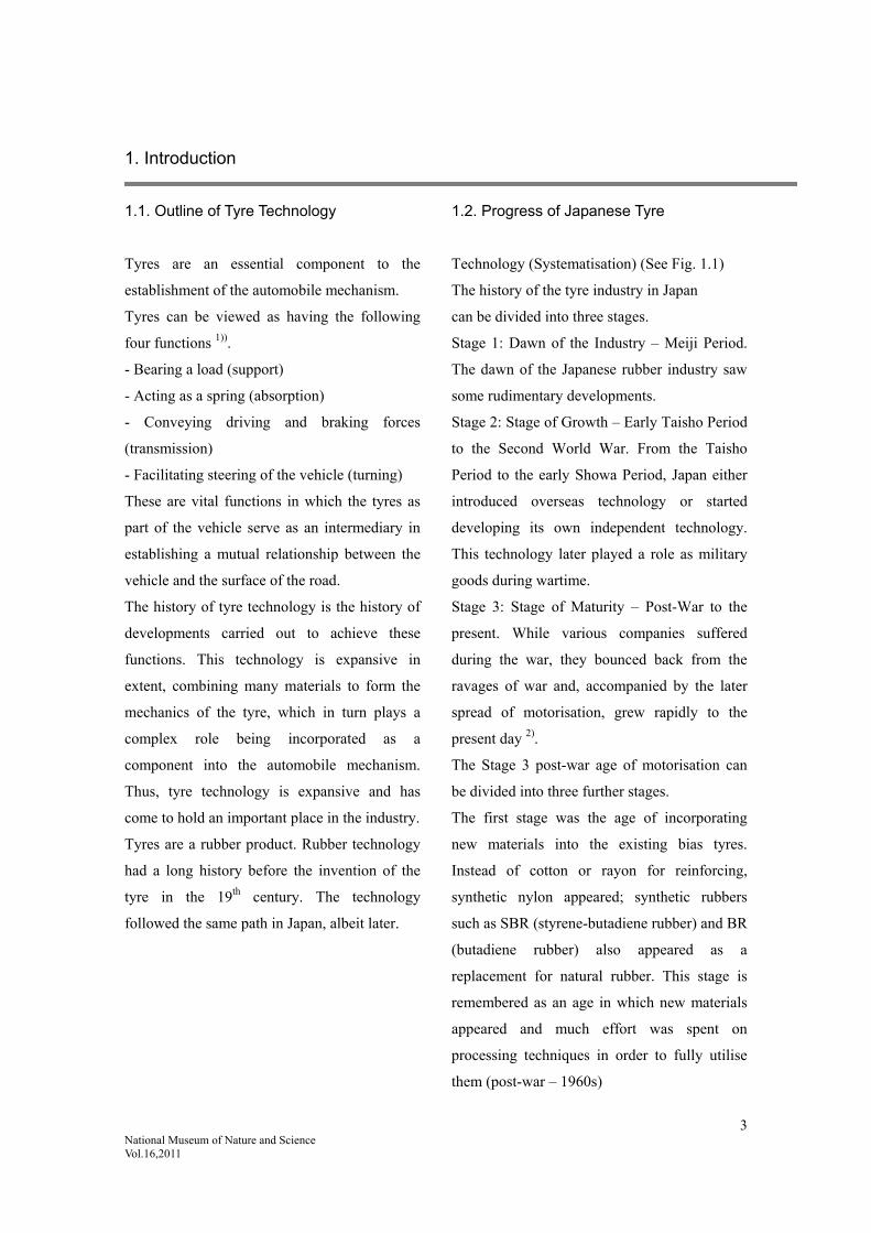
Fig. 1.4. Tyre Dimensions. Aspect Ratio = Cross-Section Width / Cross-Section Height
Undertread Belt Tread
Sidewall
RubberChafer
Inner Liner Carcass Ply
Bead Filler
Bead Chafer
Tyre Size Designations
Radial Tyre
Size of Rim Diameter (14 inches)Tyre Structure Code (Radial) Aspect Ratio (60%); Height/WidthCross-Section Width (195mm)
Ply Rating (4-ply; equivalent strength of four layers of reinforcing)
Rim Diameter (13 inches) Cross-Section Width (6.15 inches)
Bias Tyre
Tread Width
Cross-SectionHeight
Rim Width
Cross-Section Width Rim
Diameter
Out
er D
iam
eter
of
Tyr
e
7 National Museum of Nature and Science Vol.16,2011
However, stricter environmental measures will
mean further hurdles will need to be crossed in
future. Mere optimisation will not be enough;
major breakthrough will be necessary.
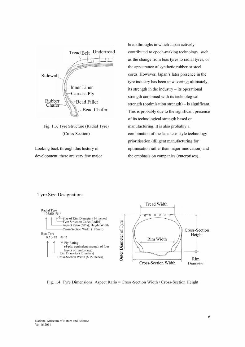
a) Bias Tyre b) Radial Tyre
a) Bias Tyre : Carcass is oriented in a biased
direction
b) Radial Tyre : Carcass is oriented in a radial
direction
Fig. 1.5. Comparison of Tyre Structures (Bias /
Radial)
Notes on Writing:
1. There are many types of tyres; it was not
possible to describe them all. This report
does not touch on racing tyres, agricultural
tyres or bicycle tyres.
2. Regarding company names. Company
names have been dealt with as follows for
the writing of this report. The former name
of the company has been used where doing
so has served to better convey the content.
(Name used): (Former name(s); current official name)
Sumitomo Rubber: Dunlop Rubber Company (Far East); Dunlop Rubber Company
(Japan); Chuo Rubber Industries(Chuō Gomu Kōgyo
Kabushikigaisya); Sumitomo Rubber Industries
Yokohama Rubber: Yokohama Rubber Manufacturing Company(Yokohama Gomu Seizou
Kabushikigaisya); Yokohama Rubber Company
Bridgestone: Bridgestone Tire Company; Nippon Tire Company(Nippon Taiya
Kabushikigaisya); Bridgestone Tire Company; Bridgestone
Corporation
Toyo Rubber: Toyo Tire Industrial Company(Tōyō Taiya Kabushikigaisya); Toyo
Rubber Manufacturing Company(Tōyō Gomu Kakou
Kabushikigaisya ) ; Toyo Rubber Industrial Company
(in order of founding)
Breaker
Carcass Carcass
Belt
8 National Museum of Nature and Science Vol.16,2011
3. Handling of Numbers in the Japanese
Text, years, months and days cited
from sources originally written
vertically, such as company histories
and The History of the Japanese
Rubber Industry, are written in
Sino-Japanese characters in the
Japanese texts. Since the Japanese
text of this report is written
horizontally, it uses Arabic numerals.
Cited references:
1) Hattori, Rokuro: Taiya no Hanashi [The Story of the Tyre], Taiseisha, June 1992, p. 34.
Jidōsha-yō Taiya no g [Studies on Automobile Tyres], Yokohama Rubber Company ed., Sankaido, 15
April 1995, p. 7, etc.
2) “Gomu Kōgyō ni okeru Gijutsu Yosoku — Jidōsha taiya wo Chūshin ni shite [Technology Forecasting
in the Rubber Industry: Focus on Automobile Tyres]”, Rubber Technology Forum, ed., (1990)
December, p. 35 – p. 43. Latter division of time periods considered with reference to “Kongo no
Taiya Gijutsu Yosoku [Future Tyre Technology Forecasting]”.
3) Gomu / Erasutomā to Mirai no Kōtsū [Rubbers / Elastomers and Future Transportation], Rubber
Technology Forum, ed., Gomutimes, March 2010, p. 69.
9 National Museum of Nature and Science Vol.16,2011
2. Creation of the Tyre
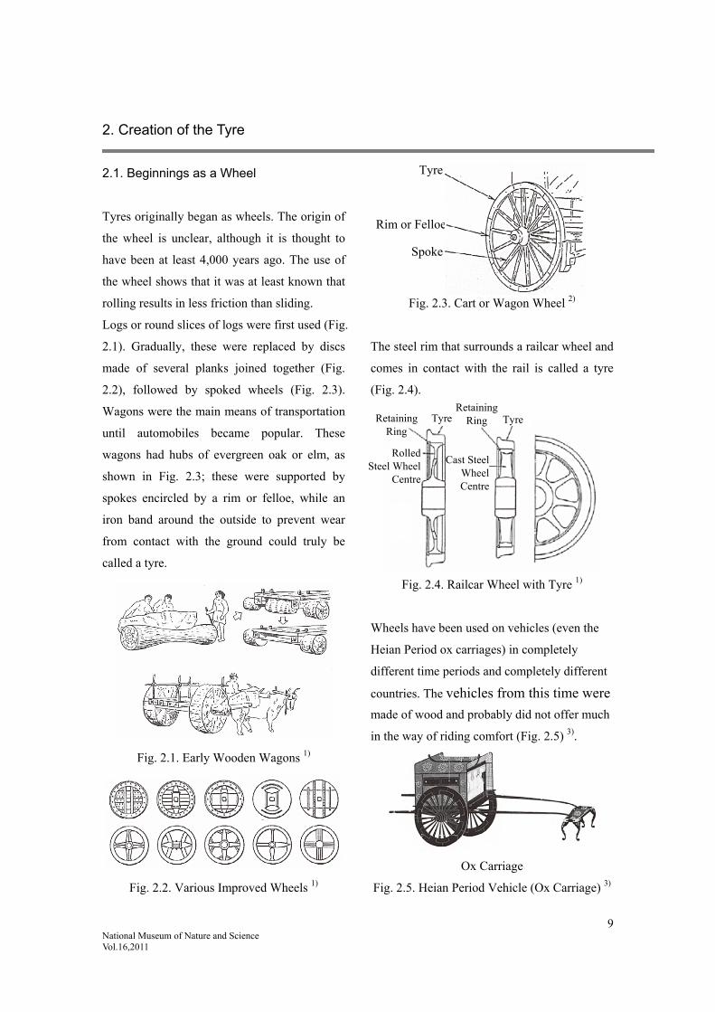
2.1. Beginnings as a Wheel
Tyres originally began as wheels. The origin of
the wheel is unclear, although it is thought to
have been at least 4,000 years ago. The use of
the wheel shows that it was at least known that
rolling results in less friction than sliding.
Logs or round slices of logs were first used (Fig.
2.1). Gradually, these were replaced by discs
made of several planks joined together (Fig.
2.2), followed by spoked wheels (Fig. 2.3).
Wagons were the main means of transportation
until automobiles became popular. These
wagons had hubs of evergreen oak or elm, as
shown in Fig. 2.3; these were supported by
spokes encircled by a rim or felloe, while an
iron band around the outside to prevent wear
from contact with the ground could truly be
called a tyre.
Fig. 2.1. Early Wooden Wagons 1)
Fig. 2.2. Various Improved Wheels 1)
Fig. 2.3. Cart or Wagon Wheel 2)
The steel rim that surrounds a railcar wheel and
comes in contact with the rail is called a tyre
(Fig. 2.4).
Fig. 2.4. Railcar Wheel with Tyre 1)
Wheels have been used on vehicles (even the
Heian Period ox carriages) in completely
different time periods and completely different
countries. The vehicles from this time were
made of wood and probably did not offer much
in the way of riding comfort (Fig. 2.5) 3).
Ox Carriage
Fig. 2.5. Heian Period Vehicle (Ox Carriage) 3)
Retaining Ring
RolledSteel Wheel
Centre
Tyre Retaining
Ring Tyre
Cast Steel Wheel Centre
Tyre
Rim or Felloe
Spoke

10 National Museum of Nature and Science Vol.16,2011
2.1.1. The Beginning of the Tyre
The discussion below draws heavily from Taiya
no Hanashi [The Story of the Tyre] 1). Vehicles
with iron or wooden wheels were difficult to
pull on rough road surfaces. Accordingly, early
tyres were the result of various inventors
competing to somehow make vehicles travel
more comfortably. Attempts were made to give
tyres greater elasticity; what is now known as
the solid tyre (a tyre made wholly from rubber
with no air inside) was invented in 1835 (see
figures below).
Fig. 2.6. Various Early Solid Tyres 1)
The first automobile with a gasoline engine was
built in 1886 by German company
Daimler-Benz. Production of this vehicle
started in France in 1890. Although this vehicle
had solid rubber tyres, later automobile
manufacturers still used metal rings. In 1895,
the first pneumatic tyre was developed for such
vehicles.
A replica of the first Benz vehicle with solid
tyres is on display at the Toyota Automobile
Museum (see Fig. 2.7).
Fig. 2.7. Benz Automobile Built in 1886
(Replica)
Fitted with Solid Tyres (Toyota Automobile
Museum Collection) 4)
2.2. History of the Tyre
The epoch-making invention of the time was
the pneumatic tyre. R. W. Thomson was the
first to invent and patent the pneumatic tyre in
1845 (see Fig. 2.8).
Fig. 2.8. Thomson’s Pneumatic Carriage Tyre
Patented 1845 (UK) 5)
This was granted a UK patent 5) relating to an
improvement in carriage wheels. The
distinguishing feature of this invention was the
elastic body around the wheel, which reduced
Rivet
Elastic belt of rubberised canvas Leather
Rim
Bolt

11 National Museum of Nature and Science Vol.16,2011
the running resistance and noise of the wheel
and improved the riding comfort, resulting in a
wheel that was also suitable for high-speed
applications such as steam vehicles. The elastic
body comprised a hollow belt made of a high
molecular substance such as rubber or gutta
percha (a type of natural rubber) and filled with
air.
Structurally, it was a pneumatic elastic belt of
rubberised canvas. Functionally, it worked on
the same principle as the tyres of today. It is
surprising to think that the same idea for the
modern-day tyre existed over 160 years ago.
This tyre was made for horse-drawn carriages.
Rubberised fabric was pasted together to form a
tube, which was riveted to a leather outer layer
and also riveted to a wooden rim.
However, it was not very effective on actual
vehicles and it was eventually forgotten. The
actual tyre was invented by Dunlop in 1888,
around 40 years after Thomson’s tyre. The idea
was taken up by J. B. Dunlop and patented
again. Dunlop’s patent was for a hollow tyre or
tube made of India rubber, fabric or other
suitable material filled with pressurised air and
fitted to a wheel by appropriate methods. As
shown in Fig. 2.9, Dunlop’s tyre comprised a
rubber tube encircling a thick wooden disc
about 40cm in diameter, covered in rubberised
canvas with the ends nailed into the disc. Not
only did it improve the riding comfort, it also
significantly reduced the rolling resistance
compared to solid rubber tyres, making it run
more comfortably 9).
Fig. 2.9. The First Dunlop Tyre Pneumatic Tyre 9) (Replica)
According to 100: The First Hundred Years of
Pneumatic Tyres 1888-1988, J. B. Dunlop
finally came up with this invention after
repeated experiments because his ten-year-old
son, Johnny, had asked him to “make my
tricycle go easier and faster”.
In his first experiment, Dunlop removed the
solid rubber tyre from a tricycle wheel and tried
to roll it along, but it fell over mid-flight. When
Dunlop rolled his pneumatic tyre along with the
same force, it rolled across the garden, hit a
door and rebounded. Having ridden a bicycle
with pneumatic tyres fitted, Johnny rated it very
highly (see Fig. 2.10).

12 National Museum of Nature and Science Vol.16,2011
Fig. 2.10. J. B. Dunlop with a Bicycle Fitted
with Pneumatic Tyres 6) 7) His Son Johnny
2.2.1. Commercialisation of the Pneumatic
Tyre
Around this time, cycling was becoming a
popular sport. J. B. Dunlop’s pneumatic tyre
appeared just as cycling was beginning to grow
in popularity and its performance was
epoch-making. Sports-loving entrepreneurs,
publishers of cycling magazines, newspaper
journalists and bicycle dealers alike joined
forces with Dunlop to commercialise the
pneumatic tyre. In November 1889, The
Pneumatic Tyre and Booth’s Cycle Agency,
Ltd. was established in Dublin, Ireland, with
capital stock of ₤25,000. J. B. Dunlop
transferred his patent rights to the company and
became a company director. Today, there is a
bronze plaque at the site, which reads, “The
first pneumatic tyre factory in the world was
started here in 1889, to make tyres under John
Boyd Dunlop’s patent of the 7th December,
1888” 10). (Fig. 2.11)
Fig. 2.11. Bronze Plaque 10)
Following the emergence of pneumatic tyres,
various efforts were put into making them
easier to use. One such initiative was to make it
easier to assemble and disassemble the tyre and
rim; two methods were devised for this purpose.
The first was the wired-on (wire-type) method
devised by C. K. Welch; the second was the
clincher (pull-on, Fig. 2.12) method devised by
W. E. Bartlett. Both were granted patents in
1890. A valve was invented that allowed air to
be let out as well as pumped in; the patent for
this was granted to C. H. Woods in 1891. Not
long after its establishment, The Pneumatic
Tyre and Booth’s Cycle Agency, Ltd. spent a
lot of money for the patent rights to these three
inventions, all of which contributed to the
expansion of the company 10). The wired-on
method (Fig. 2.12), which used a ring of steel
wire to affix the base of the carcass into the rim,
was the prototype for the modern-day method
of affixing automobile tyres to their rims 1).
13 National Museum of Nature and Science Vol.16,2011
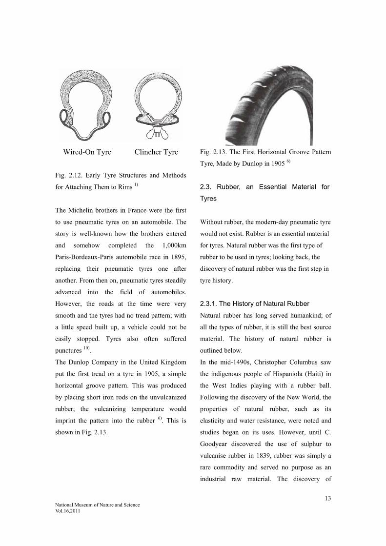
Wired-On Tyre Clincher Tyre
Fig. 2.12. Early Tyre Structures and Methods
for Attaching Them to Rims 1)
The Michelin brothers in France were the first
to use pneumatic tyres on an automobile. The
story is well-known how the brothers entered
and somehow completed the 1,000km
Paris-Bordeaux-Paris automobile race in 1895,
replacing their pneumatic tyres one after
another. From then on, pneumatic tyres steadily
advanced into the field of automobiles.
However, the roads at the time were very
smooth and the tyres had no tread pattern; with
a little speed built up, a vehicle could not be
easily stopped. Tyres also often suffered
punctures 10).
The Dunlop Company in the United Kingdom
put the first tread on a tyre in 1905, a simple
horizontal groove pattern. This was produced
by placing short iron rods on the unvulcanized
rubber; the vulcanizing temperature would
imprint the pattern into the rubber 6). This is
shown in Fig. 2.13.
Fig. 2.13. The First Horizontal Groove Pattern
Tyre, Made by Dunlop in 1905 6)
2.3. Rubber, an Essential Material for
Tyres
Without rubber, the modern-day pneumatic tyre
would not exist. Rubber is an essential material
for tyres. Natural rubber was the first type of
rubber to be used in tyres; looking back, the
discovery of natural rubber was the first step in
tyre history.
2.3.1. The History of Natural Rubber
Natural rubber has long served humankind; of
all the types of rubber, it is still the best source
material. The history of natural rubber is
outlined below.
In the mid-1490s, Christopher Columbus saw
the indigenous people of Hispaniola (Haiti) in
the West Indies playing with a rubber ball.
Following the discovery of the New World, the
properties of natural rubber, such as its
elasticity and water resistance, were noted and
studies began on its uses. However, until C.
Goodyear discovered the use of sulphur to
vulcanise rubber in 1839, rubber was simply a
rare commodity and served no purpose as an
industrial raw material. The discovery of

14 National Museum of Nature and Science Vol.16,2011
vulcanisation enabled the development of the
rubber industry. Coupled with the emergence of
the automotive industry in the 19th and 20th
centuries, this formed the basis for the
modern-day industry. Research on natural
rubber continued in the 19th century, with M.
Faraday confirming the chemical composition
of natural rubber as C5H8 in 1826. In 1860, G.
Williams dry-distilled rubber and isolated the
isoprene monomer 8).
Rubber later dramatically increased in
consumption with the growth of the automotive
industry. Since the United Kingdom had the
monopoly on 80% of the world’s cultivated
rubber, other countries struggled to secure raw
rubber.
Later, rubber became an essential military
commodity in the World Wars. Full-scale
research on synthetic rubber as a strategic
resource was carried out around the time of the
First World War (1914). Until the Second
World War (1939-45) prompted mass
production of synthetic rubber, other countries
around the world were unable to break the
United Kingdom’s monopoly.
During the First and Second World Wars, the
industrialisation of butadiene synthetic rubber
was fast-tracked because it was necessary to
ensure vast amounts of rubber for military
manoeuvres. After the wars, synthetic rubber
proved to be a worthy competitor to natural
rubber, with improvement to the quality and
reduction in the cost of SBR as well as the
development of the petrochemical industry; in
1963, worldwide synthetic rubber consumption
finally overtook that of natural rubber.
In light of such circumstances, improvements
were made to natural rubber. Efforts began in
Malaysia – the world’s largest producer of
natural rubber at the time – and other countries
to systematically replant with higher-yield
species to increase yields, improve tapping
methods (extracting rubber latex by cutting the
tree trunk), use latex secretion promoters, prune
trees while young, fertilise, carry out soil
management and prevent disease.
Rationalisation and centralisation of raw rubber
production processes meant improved quality
and reduced costs, all of which combined to
provide competition against synthetic rubber.
Some attempts were made to catch up to
synthetic rubber through chemical modification
of natural rubber and development of new
forms of natural rubber 8). Currently, natural
rubber is very highly priced, with a strong
demand for it in emerging nations.
The natural rubber tree used industrially is the
Pará rubber tree Hevea brasiliensis, which has
very low non-rubber content and a very high
yield of rubber hydrocarbons, namely
cis-1.4-polyisoprene. The latex extracted when
the bark is cut has a 30% rubber content. This
rubber content contains proteins and small
amounts of lipids,
sugars and ash. Although the latex remains
stable while inside the rubber tree, once
harvested it is prone to spontaneous coagulation
due to enzyme action, so a protectant like
ammonia is added to prevent coagulation. The
latex is a milky juice in the ductal tissue that
develops near the cambium layer within the
Hevea tree, extracted by cutting the bark
15 National Museum of Nature and Science Vol.16,2011
(tapping) of trees that are at least 5-7 years old.
The latex coagulates when acid is added to it.
The dried form of this is known as raw or crude
rubber.
Hevea rubber is polyisoprene with a 1.4-cis
structure and has very high tensile strength. It
crystallises when stretched and usually has high
mechanical strength, low heat resistance and
high abrasion resistance. Accordingly, it has a
high use ratio in high-load tyres.
Natural rubber, discovered and improved by
humans, is a high-quality rubber with superior
physical properties that has led to the formation
of a wide range of industrial fields. The
properties of natural rubber, such as its high
strength and low heat build-up, make it perfect
for tyres and it has been a key component in the
development of the modern tyre industry.
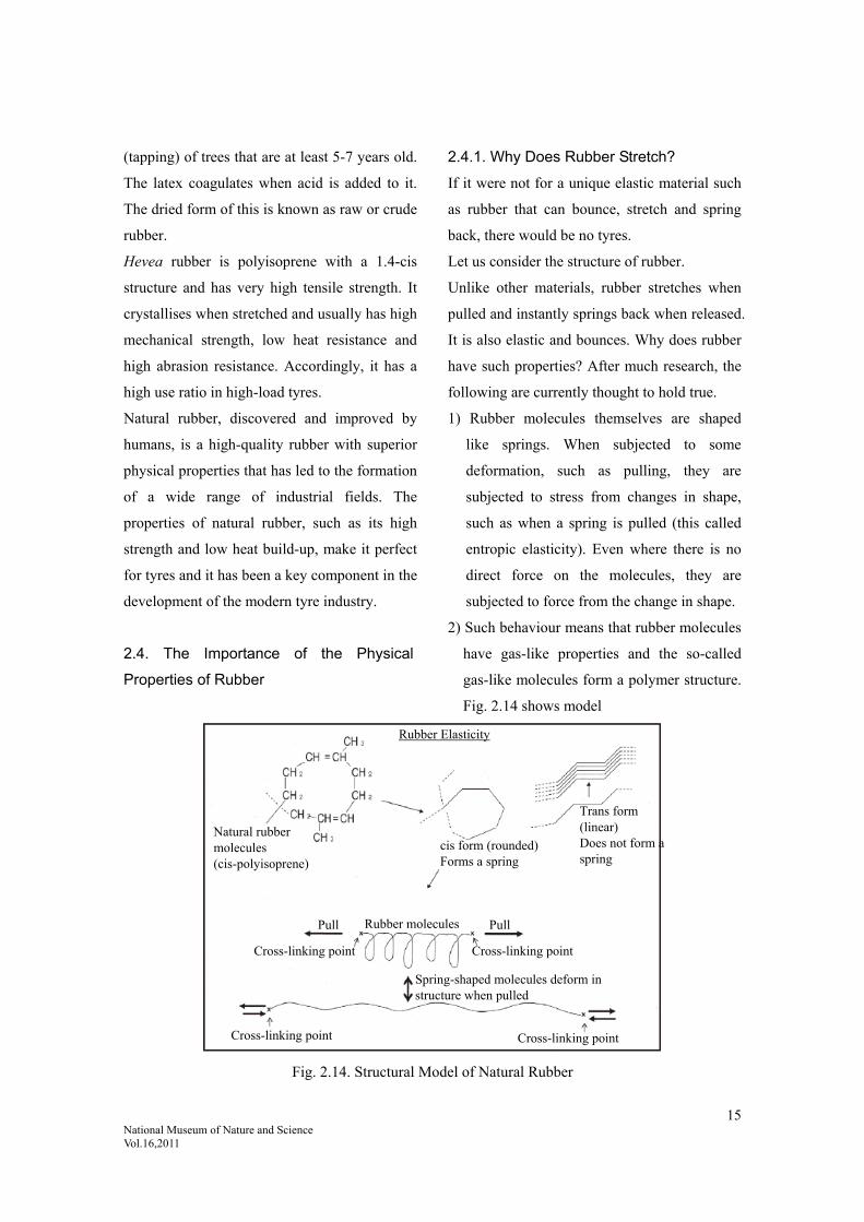
2.4. The Importance of the Physical
Properties of Rubber
2.4.1. Why Does Rubber Stretch?
If it were not for a unique elastic material such
as rubber that can bounce, stretch and spring
back, there would be no tyres.
Let us consider the structure of rubber.
Unlike other materials, rubber stretches when
pulled and instantly springs back when released.
It is also elastic and bounces. Why does rubber
have such properties? After much research, the
following are currently thought to hold true.
1) Rubber molecules themselves are shaped
like springs. When subjected to some
deformation, such as pulling, they are
subjected to stress from changes in shape,
such as when a spring is pulled (this called
entropic elasticity). Even where there is no
direct force on the molecules, they are
subjected to force from the change in shape.
2) Such behaviour means that rubber molecules
have gas-like properties and the so-called
gas-like molecules form a polymer structure.
Fig. 2.14 shows model
Fig. 2.14. Structural Model of Natural Rubber
Rubber Elasticity
Natural rubber molecules (cis-polyisoprene)
cis form (rounded) Forms a spring
Trans form (linear) Does not form a spring
Rubber molecules Pull Pull
Cross-linking point Cross-linking point
Cross-linking point Cross-linking point
Spring-shaped molecules deform in structure when pulled

16 National Museum of Nature and Science Vol.16,2011
2.4.2. The Discovery of Vulcanisation
The elasticity of rubber cannot be achieved by
rubber molecules alone; it requires
vulcanisation. This discovery by Goodyear in
1939 was the most important discovery in the
history of rubber. Vulcanisation is the process
of causing rubber molecules to bond together
(in many cases the cross-linking is achieved by
sulphur). The vulcanisation reaction causes
adjoining molecules to bond together and form
a network; any stress to any part of the network
is transmitted to the entire network, which
demonstrates rubber elasticity; in other words,
it has turned into rubber. Fig. 2.15 clarifies this
phenomenon. A standard test in the rubber
industry is to apply torsional deformation to
sulphur-added unvulcanised rubber over heat
and to measure the corresponding force
(torque) and the increased rigidity over time.
When this reaches a certain level (plateau),
vulcanisation is complete. Vulcanisation
accelerators significantly reduce the
vulcanisation time. Quicker vulcanisation has
been a major issue in the rubber industry,
particularly for tyres. Since natural rubber in
particular deteriorates when exposed to heat, a
major question has been how to complete the
vulcanisation in a shorter amount of time.
Fig. 2.15. Vulcanisation and Vulcanisation Curve
Harden
Cross-linking point Cross-linking point
Sulphur
Rubber molecules
Vulcanisation curve
With vulcanisation accelerator
Without vulcanisation accelerator
Vulcanisation time
Tor
que
17 National Museum of Nature and Science Vol.16,2011
2.5. Natural Rubber and Environmental
Issues
As environmental issues have intensified in the
21st century, natural rubber has been seen as
carbon neutral and there has been an increase in
its use.
In the 2010s, it is thought that the strong
demand for natural rubber by emerging nations
such as China and India will continue for the
time being. With other emerging nations
coming onto the scene, the price of natural
rubber will probably continue to soar for some
time yet. Conversely, there may be a shortage
of natural rubber as a raw material.
The properties of natural rubber can change
significantly when epoxy-modified. Recent
research has examined new scopes of usage for
it; accordingly, it is expected to continue to
expand in use 10) 11)
Cited references:
1) Hattori, Rokuro: Taiya no Hanashi [The Story of the Tyre], Taiseisha, 25 June 1992, pp. 2-3.
2) Watanabe, Tetsuo: Taiya no O-Hanashi [The Story of the Tyre], October 2002, Japan Standards Association, p. 13,
cited from Ichimura, Yoshio: Jidōsha Kōgaku Zensho [Automotive Engineering Compendium], (1980) Vol. 10,
Chapter 3, Sankaido, p. 170.
3) Shin Sōgō Zusetsu Kokugo [New Comprehensive Illustrated Language], Tokyo Shoseki, 2004, p. 21.
4) “Toyota Automobile Museum” Collection, 41-100 Yokomichi, Nagakute, Aichi.
5) UK Patent No. 10990.
6) 100: The First Hundred Years of Pneumatic Tyres 1888-1988, Sumitomo Rubber Industries, Ltd., p. 7.
7) Best Car, ed., Taiya no Subete ga Wakaru Hon [The Book that Tells You Everything You Need to Know About
Tyres], Sansuisha, Kodansha, 2008, p. 95.
8) Gomu Kōgyō Binran [Rubber Industry Handbook], 4th Edition, The Society of Rubber Science and Technology,
Japan, 20 January 1994, pp. 179-182.
9) Watanabe, Tetsuo: Taiya no O-Hanashi [The Story of the Tyre], October 2002, Japan Standards Association, p. 17,
cited from Bridgestone Corporation Public Relations Department (1987): Taiya Hyakka [Tyre Encyclopaedia], p.
15, Toyo Keizai, Inc.
10) Sumitomo Gomu Hyakunen-shi [Hundred-year History of Sumitomo Rubber], Sumitomo Rubber Industries, Ltd.,
December 2009, pp. 33-35.
11) Tokushu Erasutomā no Mirai Tenkai o Saguru Part I [Exploring Future Development of Special Elastomers Part
I], Rubber Technology Forum, ed., Gomutimes, pp. 21-22, 1992, and Laid-Open Patent No. 2000-169504:
Sumitomo Rubber Industries, Ltd., Kao Co., Ltd., Fuji Latex Co., Ltd., and Higashi Kagaku, Co., Ltd.

18 National Museum of Nature and Science Vol.16,2011
3. Dawn of the Japanese Rubber Industry (The Age of Early Compounding
Techniques)
3.1. Meiji Period – Early Taisho Period
As mentioned in the previous chapters,
Japanese tyre production started at the end of
the Meiji Period (initially bicycle and rickshaw
tyres; the first automobile tyres were produced
in the second year of the Taisho Period, 1913).
The core technologies at the time were rubber
compounding and vulcanisation. Let us now
address the rubber technology of the day.
The rubber industry was just dawning at the
time; rubber compounding and vulcanisation
were being developed independently through
trial and error.
3.1.1. Late Meiji Rubber Technology
The Japan Rubber Ball Factory(Nihon
Gomudama Seizōzyo) (or more correctly, the
Japan Rubber Factory(Nihon Gomu Seizōzyo),
according to Hyōgo Gomu Kōgyō-shi [History
of the Hyogo Rubber Industry]; author note) is
said to have been established in Kobe in 1885,
manufacturing balls and pillows (Kōbe Kaikō
Sanjū-nen-shi [Thirty-Year History of the
Opening of Kobe Port], published 1898) 3).
However, it is generally said that the Japanese
rubber industry began in 1886. Namely, the
Tsuchiya Rubber Factory (later the Mitatsuchi
Rubber Manufacturing Partnership(Mitatsuchi
Gomu Seizō Gōmēgaisya)) was established at
the end of that year, moving on from repairing
personal diving costumes to successfully
vulcanising rubber. Accordingly, this formed
the foundation of the modern rubber industry in
Japan, at least technically speaking. This was
around 50 years after Goodyear’s discovery of
vulcanisation 3) 2).
In this era of compound-focused development,
experimentation was carried out on rubber
compounds and many compounding specialists
emerged, having mastered the art of
compounding. The compounds were kept secret,
technical knowledge was monopolised and they
received higher salaries than factory managers.
This continued until around the end of the
Taisho Period. The technology changed
drastically with the invention of organic
vulcanisation accelerators. Before there were
organic vulcanisation accelerators, the most
important issue was how to combine inorganic
vulcanisation agents with inorganic
vulcanisation accelerators.
Let us now examine compounding techniques.
This discussion draws heavily from Yamada,
Hitoshi: “Haigō-Shi [Compounding
Specialists]”, Haigō no Tatekata
[Compounding Techniques], Compounding
Techniques Research Subcommittee, The
Society of Rubber Science and Technology,
Japan, ed.) 1). (Hitoshi Yamada is a chief
examiner for the Compounding Techniques
Research Subcommittee, The Society of
Rubber Science and Technology, Japan and has
researched these compounding specialists in
depth; the author is also a member of the
Subcommittee.)

19 National Museum of Nature and Science Vol.16,2011
As mentioned previously, the Japanese rubber
industry is generally said to have started in
1886 with the establishment of the Tsuchiya
Rubber Factory. The Tsuchiya Rubber Factory
changed its name to Mitatsuchi Rubber
Manufacturing Partnership in 1892. Mitatsuchi
merged with Showa Rubber Co., Ltd. in 1945.
(1) Early Technology (Mitatsuchi Technology)
Despite reference to original documentation,
early attempts at vulcanisation by Mitatsuchi
resulted in a series of failures with no specific
method of vulcanisation attained 15).
Following much trial and error, researchers
settled on a type of heated-stone method used
for roasting sweet potatoes. The final method
adopted was a unique vulcanisation method in
which unvulcanised rubber was buried in a
container of small stones and sand and
gradually heated to produce even vulcanisation 4) 5) 9) 15). This was also adopted by other
companies in 1904-1905 4) 11) 16). Various
compounds were used, such as adding lime or
litharge (lead oxide; PbO) 15). During mixing,
the natural rubber was cut with scissors, soaked
in volatile oil until swollen, then transferred to
a roller or mortar 4) 5) 17). It then had to be
pounded continuously with a pestle for several
hours and workers are said to have become
intoxicated from the volatile oil 15).
3.1.2. The Rubber Industry at the End of
the 19th Century and Start of the 20th
Century
A few years after Mitatsuchi was established
(from 1888 onwards), several rubber seal
businesses started operating 4) 11). The industry
started growing in Japan in the 1890s; in 1894,
the Yoshida brothers, who had cold
vulcanisation technology, established a rubber
firm in Kobe 4-7) 11) 12). In 1896, the Tokyo
Rubber Factory(Tokyo Gomu Seisakuzyo) was
launched, as was the Yoshida Rubber
Factory(Yoshida Gomu Seizō), founded by
former Mitatsuchi employees 4) 9). Hirano
Works(Hirano Seizōzyo) 18) and Fujikura
Rubber(Fujikura Gomu) 19) also started around
the same time.
Although rubber factories were opening across
the country, these were home-based businesses 8) 9). In 1900, there were only two rubber
factories nationwide that employed ten or more
regular staff members. Even by around 1909,
there were no more than 19 factories that
employed five or more staff members 4) 5) 8) 13).
At the end of 1907, the three major companies
in Tokyo Prefecture were Mitatsuchi with 229
employees, Meiji Rubber with 140 and Japan
Rubber with 100 4) 12). Mitatsuchi had held a
near monopoly in the rubber industry for ten
years until Meiji Rubber was founded 4) 9) 10) 14).
All rubber shops sought out Mitatsuchi’s
compound 14). This suggests a relationship
between the compounding specialists and
Mitatsuchi.
3.2. The Rubber Industry in the Late Meiji
Period (Start of the Tyre Industry; author
note)
The British-funded Japan Ingram Rubber
20 National Museum of Nature and Science Vol.16,2011
Company (hereinafter abbreviated as ‘Ingram’)
was founded in 1908, while the Dunlop Rubber
Company (Far East) (now Sumitomo Rubber
Industries; hereinafter abbreviated as ‘Dunlop’)
was founded in 1909 4-7) 9) 11-13). Both had the
same capital system; Ingram merged into
Dunlop in 1911 4-7) 9) 11) 12).
Bicycles grew in popularity from around 1907,
precipitating a sudden rise in demand for tyres 4) 5) 9-12). There was an increased demand for
rickshaw tyres as well; companies leapt into
production. Mitatsuchi and Meiji Rubber made
prototypes in the early 1900s, launching into
full-scale production around 1908 4) 5) 9).
The Japanese rubber industry followed
contemporary trends and gradually built up its
capabilities by imitating the technology of
Dunlop and Ingram.
3.2.1. Dunlop
Dunlop had the best technologies and facilities
with large amounts of capital provided by
Dunlop in the United Kingdom. According to
Nihon Gomu Kōgyō-shi [The History of the
Japanese Rubber Industry], “the Dunlop
factory was also called the rubber school”, with
many engineers passing through its doors and
playing active roles in other rubber companies 4) 5) 7) 12). The rapid spread of technology such as
Dunlop Rubber’s “compounding” techniques is
said to be one reason why so many rubber
factories were established in Kobe 4) 5) 9).
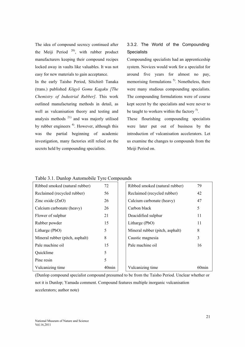
3.2.2. Changes to Tyre Compounds
Dunlop/Mitatsuchi Compounds
Dunlop compounds are shown in Table 3.1,
based on Gomu Haigō Kokinshū [Collection of
Rubber Compounds Old and New], published
in 1940, although it is not clear if they were
used in the late Meiji Period. A fixed natural
rubber content is characteristic of Dunlop 2).
A significant amount of Mitatsuchi compounds
were versions of Dunlop compounds, giving an
Oriental take on the British rubber compounds.
Mitatsuchi quietly built up its compounding
techniques and slipped in to take the reins of
the Japanese rubber compounding domain
alongside Dunlop. The two of them dominated
from 1897 to the early Taisho Period and were
still making a number of noteworthy
achievements in the early Showa Period 14).
3.3. The Rubber Industry from the Late
Meiji Period to the Early Taisho Period
In the late Meiji Period, the Japanese rubber
industry acquired some technology, but
remained in an embryonic stage. Rather than an
academic discipline, it involved “using
chemicals and persisting with sulphur, the
mixing of which was a closely guarded secret at
each factory” (discussion with Masanosuke
Sasabe of Bando Chemical Industries). There
were no testing facilities; compounding relied
on experience and intuition. However, each
company kept their compounds a secret while
each trying to work out
3.3.1. The Rise of Compounding
Specialists
The Rubber Industry in the Late Taisho Period
21 National Museum of Nature and Science Vol.16,2011
The idea of compound secrecy continued after
the Meiji Period 20), with rubber product
manufacturers keeping their compound recipes
locked away in vaults like valuables. It was not
easy for new materials to gain acceptance.
In the early Taisho Period, Sōichirō Tanaka
(trans.) published Kōgyō Gomu Kagaku [The
Chemistry of Industrial Rubber]. This work
outlined manufacturing methods in detail, as
well as vulcanisation theory and testing and
analysis methods 21) and was majorly utilised
by rubber engineers 4). However, although this
was the partial beginning of academic
investigation, many factories still relied on the
secrets held by compounding specialists.
3.3.2. The World of the Compounding
Specialists
Compounding specialists had an apprenticeship
system. Novices would work for a specialist for
around five years for almost no pay,
memorising formulations 5). Nonetheless, there
were many studious compounding specialists.
The compounding formulations were of course
kept secret by the specialists and were never to
be taught to workers within the factory 5).
These flourishing compounding specialists
were later put out of business by the
introduction of vulcanisation accelerators. Let
us examine the changes to compounds from the
Meiji Period on.
Table 3.1. Dunlop Automobile Tyre Compounds
Ribbed smoked (natural rubber) 72
Reclaimed (recycled rubber) 56
Zinc oxide (ZnO) 26
Calcium carbonate (heavy) 26
Flower of sulphur 21
Rubber powder 15
Litharge (PbO) 5
Mineral rubber (pitch, asphalt) 8
Pale machine oil 15
Quicklime 5
Pine resin 5
Vulcanizing time 40min
Ribbed smoked (natural rubber) 79
Reclaimed (recycled rubber) 42
Calcium carbonate (heavy) 47
Carbon black 5
Deacidified sulphur 11
Litharge (PbO) 11
Mineral rubber (pitch, asphalt) 8
Caustic magnesia 3
Pale machine oil 16
Vulcanizing time 60min
(Dunlop compound specialist compound presumed to be from the Taisho Period. Unclear whether or
not it is Dunlop; Yamada comment. Compound features multiple inorganic vulcanisation
accelerators; author note)

22 National Museum of Nature and Science Vol.16,2011
3.4. Compounding Agents from the End of
the Meiji Period to the Taisho Period
Matsutarō Hanaki states the following 9) 23).
“At that time, Meiji Rubber and Toyo Rubber
had mostly the same rubber compounding
agents, with the most important being sulphur
or slaked lime as an accelerant. Other agents
used included zinc oxide (ZnO), sedimentary
calcium carbonate, magnesium carbonate, with
browning achieved by a mix of burnt-pine ink
or lamp soot for black and red iron oxide for
red, and golden antimony sulphide.”
Several compounding agents are described
below.
(i) Zinc Oxide (ZnO)
Zinc oxide was the most commonly used
reinforcing agent in the Meiji Period. It was
replaced by calcium carbonate and carbon in
the late Taisho to early Showa Period. As
organic accelerators grew in popularity from
the end of the Taisho Period, more modern
accelerators began to be more widely used 4).
(ii) Basic Magnesium Carbonate
Various chemical formulations of compounding
agents, such as 3MgCO3·Mg(OH)2·3H2O,
4MgCO3·Mg(OH)2·5H2O, and
5MgCO3·2Mg(OH)2·5H2O, were called
magnesium carbonate or light magnesium
carbonate 1) 4) 8) 24). These were first used in
rubber in 1918 and were used in most rubber
products by the end of the late Taisho to early
Showa Period 4).
(iii) Calcium Carbonate
Initially, heavy calcium carbonate was often
used, under names such as whitening, calcium
carbonate or coal stone. While light calcium
carbonate was first mass produced in 1919 by
Shiraishi Kogyo, its value was not appreciated
for quite some time afterwards. However, this
was gradually recognised through research at
the National Osaka Laboratory(Kokuritsu
Ōsaka Shikenzyo) ; by the early Showa Period,
it had become a major rubber chemical
alongside zinc oxide and magnesium carbonate 4) 20).
Fatty-acid-soap surface-treated calcium
carbonate was also developed in the early
Showa Period. While this, too, was
underappreciated to begin with, it made a
significant contribution to the field of rubber
compounding once research at the University of
Akron demonstrated its superiority as a
reinforcing filler for rubber 20).
(iv) Carbon Black
Imported since 1901, it was first used as a
colourant. It grew in popularity as a reinforcing
agent for tyres from the end of the Taisho
Period and was being produced domestically in
1931 4).
(v) Accelerators
Initially, “the three most important accelerators
in compounds were slaked lime, litharge and
magnesia; it took experience to use these
properly” (discussion with Tetsunosuke Mori,
formerly of Kakuichi Rubber) 4). This was the
reason that rubber compounding was thought to
be difficult and kept secret 25). “Following a
visit by a British compounding specialist to
Meiji Rubber, other compounds were known

23 National Museum of Nature and Science Vol.16,2011
about, but only quicklime was used”
(discussion with Hanaki) 23). Inorganic
chemicals such as sodium silicate were also
used as kinds of accelerators, but were not
called accelerators 4) 23).
The spread of organic accelerators in Japan can
be pinpointed to this time period, with some
factories starting to use them from this time on.
3.5. The Rubber Industry in the Late Taisho
Period
The use of magnesium carbonate made it
possible to produce clear rubber, as well as
improvements in the physical properties of the
rubber. By the late Taisho Period, there had
been significant development in the production
of rubber boots from these rubber compounds;
these were even being exported overseas 4) 5).
From the manufacturing perspective, there was
a division of labour between vulcanisation and
production, with mixing factories carrying out
compounding and simple vulcanisation, while
production factories carried out production 4) 5).
The preface to Gomu Haigō-hō [Rubber
Compounding Methods], published in 1922,
provides an insight into the state of the rubber
industry at the time. “Manufacturing methods,
particularly compounding methods, are kept
completely secret; there are many people who
have worked in production for many years and
do not even know the components of their
products.” This suggests the presence of
compounding specialists.
For comparative reference between two typical
compounds of the time, the sample compound
cited in the literature (Gomu Haigō-hō:
Fukuoka, Harutarō 1922 [Rubber
Compounding Methods: Harutaro Fukuoka
1922]) in Gomu Haigō-hō [Rubber
Compounding Methods] 26), published in 1922,
and a ‘Mitatsuchi-style’ compound are shown
in Tables 3.2 and 3.3.
Table 3.2. Sample Automobile Tyre
Compounds 26) 14)
Fukuoka Mitatsuchi
Ribbed smoked (natural rubber)
100 100
Magnesium carbonate 21 23
Brown factice (softening agent, processing agent)
9 9
Carbon black 4 5
Deacidified sulphur 4 4
Paraffin 3 3
Caustic magnesia 4 3
Vulcanizing time 50 min 50 min
Table 3.3. Sample Automobile Tyre
Compounds 26) 14)
Fukuoka Mitatsuchi
Ribbed smoked (natural rubber)
100 100
Zinc oxide (ZnO) 29 29
Magnesium carbonate
18 18
Deacidified sulphur
5 5
Litharge (PbO) 7 7
Carbon black 4 4
Mineral rubber 5 5
Vulcanizing time 60 min 120 min
Fukuoka: Gomu Haigō-hō [Rubber
Compounding Methods],

24 National Museum of Nature and Science Vol.16,2011
Fukuoka, Harutaro (1922)
Mitatsuchi: Gomu Haigō Kokinshū
[Collection of Rubber
Compounds Old and New] 14), Moriyama, Tokichirō
(1940)
(Compounds presumed to be from the early to
mid-Taisho Period; Yamada comment)
The two tables show that the compound
recorded in Gomu Haigō-hō [Rubber
Compounding Methods] published in 1922 is
almost identical to the ‘Mitatsuchi-style’
compound cited in the literature 14) (both
sources show the compounding amounts in
terms of weight used, given in the tables as
parts per hundred rubber). Since early rubber
compounds were more complex, these sample
compounds were probably a simplified version
used for a public lecture. Literature published
in 1943 states that “complex formulations were
effective for keeping compounds a secret, but
nothing more,” while another source
conjectured that compounding specialists added
in unnecessary raw materials to make it
needlessly complicated so that the compounds
could not be easily learned 27). The parts per
hundred rubber (phr) representation indicates
the weight of other compounding agents in
proportion to 100 parts (weight) of natural
rubber.
It seems that progress had been made on the
research/education front by the late Taisho
Period, with Gomu Seizō Kagaku [The
Chemistry of Rubber Manufacturing] 28)
published in 1924 and Gomu no Kenkyū
[Studies in Rubber] 29) published in 1926.
Gomu Seizō Kagaku [The Chemistry of Rubber
Manufacturing] was a publication by Waseda
University; Gomu no Kenkyū [Studies in
Rubber] was a book based on lectures at
Tohoku Imperial University. A sample
compound from Gomu Seizō Kagaku [The
Chemistry of Rubber Manufacturing] is shown
in Table 3.4.
Table 3.4. Sample Automobile Tyre
Compounds 28)
Pará (wild rubber) 40
Caucho (wild rubber) 27
Upper Congo 27
Reclaimed 13
Zinc oxide (ZnO) 17
Lime 1
Sulphur 9
(Compounds presumed to be from the late
Meiji to early Taisho Periods; Yamada
comment)
Upper Congo; unclear but probably wild rubber 8)
Gomu Seizō Kagaku [The Chemistry of Rubber
Manufacturing] has a detailed record on
vulcanisation accelerators; Table 3.5 shows the
changes in sample compounds 28).
Table 3.5. Changes in Tyre Tread Compounds 1) 4) 8)

25 National Museum of Nature and Science Vol.16,2011
1912
(Meiji~Taisho)
Reinforcing agent : zinc flower Colourant : lamp black Accelerators : slaked lime, magnesia, aniline
1918 Carbon black and accelerators appear
1933
Carbon black and accelerators become popular Vulcanisation time reduces due to accelerator combination Effectiveness of anti-ageing agents becomes clear
Generally speaking, the amount of rubber
increased while the amount of sulphur
decreased.
Automobile tyre compounds had reached the
highest level of technology available at the
time.
3.5.1. Popularisation of Vulcanisation
Accelerators
(1) Inorganic Accelerators
While metal oxides such as slaked lime and
magnesia had been used as vulcanisation
accelerators in the Meiji Period, the new
inorganic accelerator developed by Matsutarō
Hanaki in the early Taisho Period was a fired
basic lead carbonate and was promoted in
1918-19. It is said to have been developed
following repeated research and analysis on
compounds imported from the United States.
Since Goodyear used basic lead carbonate as an
accelerator, this is said to be related technology 30).
This had the effect of reducing the vulcanising
time from 1-3 hours to 15 minutes.
(2) Organic Accelerators
Compound-focused rubber technology
progressed with compounding specialists at the
core.
The central technology was vulcanization
speed; the vulcanization accelerators of the day
were inorganic vulcanization accelerators.
Vulcanization time could be adjusted through
proficient use of vulcanization accelerators;
accordingly, these accelerators were the most
important technology the compounding
specialists had. The discovery of organic
vulcanization accelerators reduced the
vulcanization time even further and it was
theorised that the vulcanization phenomenon
was an organic reaction. Thus, there was a
transition from a secret technology formulated
by compounding specialists using complex
inorganic accelerators to a theoretical
technology; the world of rubber compounds
gradually transitioned from the domain of
compound specialists to the domain of organic
chemistry, making the compound specialists
obsolete.
Compounds from this time on became
fundamentally simplified, closer to the
compounds of today.
3.5.2. Popularisation of Organic
Accelerators
While the timing of the popularisation of
organic accelerators in Japan cannot be
precisely defined due to differing accounts
between factories, it was after 1920, at the end
of the Taisho Period or start of the Showa
Period 1) 4) 14) 23) 31). It is very likely to have been
from around 1920, as George Oenschlager
(who discovered organic accelerators) is said to
26 National Museum of Nature and Science Vol.16,2011
have visited Yokohama Rubber in 1919 and
passed on some cutting-edge compounding
techniques 4) 23).
New compounds based on organic accelerators
were adopted by industrial laboratory
employees and researchers as “compounds that
apply scientific principles”, but were generally
not used in practice 14). This is because the
Japanese rubber industry at the time was
largely dominated by the Mitatsuchi and
Dunlop schools and researchers could not
become active enough under that influence.
Many engineers in the Mitatsuchi and Dunlop
schools in the late Taisho Period did not know
about changes in formulation, believing the
idea that rubber would become brittle if
accelerators were used 4) 14).
Many would say that the expensive organic
accelerators are useless, and that lime was
enough 23). Many rubber companies at the time
had no testing equipment and no confidence in
using new compounding agents. However, once
Japan Rubber, which had good testing facilities,
placed a substantial order, it immediately began
to be used 4).
Meanwhile, Mitatsuchi – arguably the mother
of the compounding specialists, Meiji Rubber,
Furukawa, Fujikura and other companies
started importing or producing their own
accelerators from the end of the Taisho Period 14). By some accounts, some had been using
these since the end of the Meiji Period or start
of the Taisho Period; several other companies
were secretly using organic accelerators 4) 8) 14)
23).
The Great Kanto Earthquake of 1923 had a
huge impact. Since all-purpose inorganic
accelerator compounds had a long
vulcanization time, a large number of metal
moulds had to be set up for mass production.
Despite organic accelerators having a shorter
vulcanisation time, they would mean that the
substantial investment that went into these
metal moulds would have gone to waste. This
factor, combined with apprehension about the
effectiveness of the new accelerators, resulted
in many factories putting off introducing the
new accelerators. However, due to the
earthquake, the metal moulds had to be rebuilt;
this resulted in a growing trend towards using
organic accelerators 22) 23).
Despite some twists and turns along the way,
organic accelerators grew in popularity,
resulting in a dramatic reduction in
vulcanization time and improved product
quality 4).
3.5.3. Disclosure of Compounds
In the early Showa Period, information on
compounds was beginning to be made available
to the public. When Heisen Yoko established
its affiliated rubber laboratory in 1928, it was
completely open to the industry 4) 22) 23) 32). The
monthly magazine Gomu [Rubber] was
published and distributed to factories from
1933 onwards, explaining how to use chemicals
and providing data on accelerators 4) 5) 32).
Dunlop also began inviting British engineers to
provide open lectures on basic compounds in
the early Showa Period 4). Prior to this, the
Ministry of Communications and
Transportation had published the results of tests

27 National Museum of Nature and Science Vol.16,2011
on accelerators in 1924 4).
3.5.4. The Fate of the Compounding
Specialists
Thus, as organic accelerators grew in
popularity, the rubber industry underwent an
epoch-making transition from an alchemical
stage with secret mixtures made compounding
specialists to a modern industry based on
science and technology.
There was also an increase in so-called
educated engineers.
Consequently, the revolution in compounding
due to organic accelerators and the emergence
of orthodox-educated engineers spelled the end
for the compounding specialists.
3.5.5. Comparison of the Mechanisms of
Inorganic and Organic Vulcanisation
Accelerators
(1) Inorganic Vulcanization Accelerators
As mentioned previously, during the age of
inorganic vulcanization accelerators, metal
oxides such as litharge (lead oxide; PbO) or
zinc oxide (ZnO) were used in addition to
various other kinds of compounding agents.
The use of metal oxides also required the use of
organic acids, such as oleic acid or stearic acid.
The reaction formula below (Fig. 3.1) shows
the cross-linking reaction mechanism between
organic acid and PbO. The Pb forms a metallic
soap, which makes a polysulphide, releasing
active sulphur and accelerates vulcanization 34).
Fig. 3.1. Vulcanisation Mechanism by means of
an Inorganic Vulcanization Accelerator
(2) Organic Vulcanization Accelerators
Let us now describe the mechanism of action of
organic vulcanization accelerator MBT
(2-Mercaptobenzothiazole), still in use today.
Vulcanization accelerators act as a catalyst for
a sulphur cross-linking reaction. At this point,
the reaction between the vulcanization
accelerator and zinc oxide is essential. Both are
necessary; without either of them, vulcanization
would not work. The reaction formula is given
in Fig. 3.2.
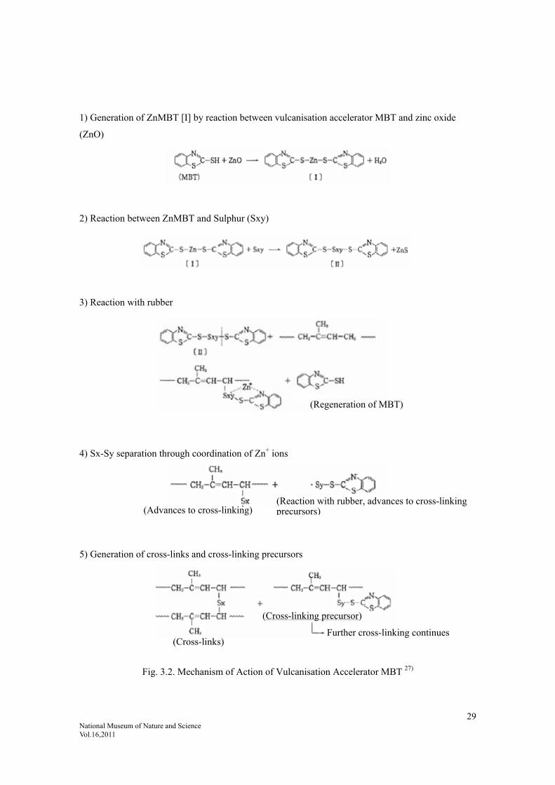
Sulphur chains are trapped between MBT
(reactions 1-2). The sulphur breaks down
within the sulphur chains and reacts with the
rubber molecules (reactions 3-4). A reaction
takes places between the sulphur and the
molecules and cross-linking is established
(reaction 5) 27).
3.6. The Rubber Industry in the First Half of
the Showa Period
Let us now outline the state of the rubber
industry in the early Showa Period.
3.6.1. The Rubber Industry in the Early
Showa Period
(1) Use of Organic Accelerators
While organic accelerators gained popularity
considerably at the end of the Taisho and start
of the Showa Period, it appears that they were
not readily mastered. Even a source published
in 1940 14) notes that accelerators were used in

28 National Museum of Nature and Science Vol.16,2011
token small amounts and not very effectively.
Furthermore, small amounts of accelerators
made the rubber harder to scorch (burn;
prevulcanization) and easier to extrude; some
compounds were researched out to that end 14).
Research divisions of major factories used an
academic approach to come up with
compounds. Ninety per cent of smaller
factories used the old methods of secretly
stealing, memorising or otherwise learning
compounds 33).
(2) The “Academic” Movement
However, the academic initiatives appeared to
be reliable and The Society of Rubber Science
and Technology, Japan was established in 1928.
Gomu Seizō-Hō [Rubber Manufacturing
Methods] recorded basic sample compounds,
such as those given in Table 3.6, that are still
used today.
While research on compounds progressed, the
aforementioned Gomu Seizō-Hō [Rubber
Manufacturing Methods] 25) also recorded
sample compounds for automobile tyres, such
as those given in Table 3.7, that are still used
today.
29 National Museum of Nature and Science Vol.16,2011
1) Generation of ZnMBT [I] by reaction between vulcanisation accelerator MBT and zinc oxide
(ZnO)
2) Reaction between ZnMBT and Sulphur (Sxy)
3) Reaction with rubber
4) Sx-Sy separation through coordination of Zn+ ions
5) Generation of cross-links and cross-linking precursors
Fig. 3.2. Mechanism of Action of Vulcanisation Accelerator MBT 27)
(Regeneration of MBT)
(Advances to cross-linking)(Reaction with rubber, advances to cross-linkingprecursors)
(Cross-links)
(Cross-linking precursor)
Further cross-linking continues

30 National Museum of Nature and Science Vol.16,2011
Table 3.6. Basic Compound from Gomu
Seizō-Hō [Rubber Manufacturing Methods]
Raw Rubber 100
Sulphur 0.5-3.5
Accelerator 0.5-1.5
Zinc oxide (ZnO) 1.0-10
Stearic acid 0.5-2
Anti-ageing agent 0.25-1.5
Other, reinforcing agent (carbon black,
magnesium carbonate, clay)
Filler, softener, colourant
Table 3.7. Automobile Tyre Compound
Smoked sheet (natural rubber) 100
Mineral rubber 5
Carbon black 40
Zinc oxide (ZnO) 5
Stearic acid 1
Binder 1
Anti-ageing agent 1
DM (organic vulcanisation accelerator) 0.8
Sulphur 3
(Probably an early Showa Period compound;
Yamada comment)
Here, an accelerator is used in an actual
compound for automobile tyres. The compound
in the table is almost identical to the compound
in Gomu Haigō-Hō [Rubber Compounding
Methods], published in 1958 24). It can thus be
assumed that wartime compounding techniques
had reached a reasonable level. DM
(Benzothiazile disulphide) is a thiazile organic
vulcanisation accelerator like the
aforementioned MBT.
(Refer to) modern compound samples (natural
rubber tyres)
Natural rubber 100, zinc oxide (ZnO) 5, stearic
acid 1-2, carbon black 50-60, anti-ageing agent
1, oil 1-5, sulphur 1-2, vulcanisation accelerator
(NS or CZ) 1-2.
NS: N-Oxydiethylene-2-benzothiazole
sulfenamide
CZ: N-cyclohexyle-2-benzothiazole
sulfenamide
3.7 Summary
Looking at these details, we can say that
the invention of organic vulcanisation
accelerators that allowed control over
vulcanisation was a major breakthrough
and revolution in the development of the
rubber industry. The main points are as
follows.
1. Improved productivity due to reduced
vulcanisation time
2. Less deterioration of the rubber due to
shorter exposure time during
vulcanisation
3. Rubber shifted from an
experience-based technology to a
chemical-theory-based technology
4. Theorisation meant redundancy of
compounding specialists, who had
previously made their living from
secret compounds
The above compound is thought to be

31 National Museum of Nature and Science Vol.16,2011
from the early Showa Period, indicating
that compounding specialists had
disappeared by the end of the Taisho
Period.
Nevertheless, organic vulcanisation
accelerators were an American invention;
the major change in rubber technology
following the introduction of this
technology can be said to exemplify how
the Japanese introduce technology, learn
it and then improve it to make it their
own.
Cited references:
1) Yamada, Hitoshi: “Haigō-Shi [Compounding Specialists]”, Gomu Haigō no Tatekata [Rubber Compounding
Techniques], Vol. 11, Compounding Techniques Research Subcommittee, The Society of Rubber Science and
Technology, Japan, March 2009, p. 80.
2) Kaneko, Hideo: Ōyō Gomu Kakō Gijutsu 12-kō [Applied Rubber Processing Technology, Lecture 12], Taiseisha,
1988.
3) Nihon Gomu Kōgyō-shi [The History of the Japanese Rubber Industry], Vol. 1, The Japan Rubber Manufacturers
Association, ed., 1 November 1969, pp. 42-45.
4) Nihon Gomu Kōgyō-shi [The History of the Japanese Rubber Industry], 1-3, The Japan Rubber Manufacturers
Association, ed., Toyo Keizai, Inc., 1969-1971.
5) Hyōgo Gomu Kōgyō-shi [History of the Hyogo Rubber Industry], Teranishi, Yūzō and Hyogo Rubber
Manufacturers Association, 1978.
6) Gomu Kōgyō no Hatten [Development of the Rubber Industry], Ikeo, Katsumi, Commerce and Industry
Association, 1948.
7) Danroppu Mizumakura 70-nen no Ayumi [The 70-Year History of the Dunlop Water Pillow], Sumitomo Rubber
Industries, 1995.
8) Aoe, Ichirō: Journal of The Society of Rubber Science and Technology, Japan, Vol. 41, pp. 47, 620, 1948; Vol. 42,
p. 1024, 1969, Changing Trends in Rubber Chemicals.
9) Meiji Gomu Hachijū-nen-shi [The Eighty-Year History of Meiji Rubber], Meiji Rubber & Chemical Co., Ltd.
Company History Editing Office, 1980.
10) Nihon Gōseigomu Kabushikigaisha Jūnenshi [The Ten-Year History of the Japan Synthetic Rubber Company],
Japan Synthetic Rubber Company, 1968.
11) 20 Seiki wo Hiraita Gomu Zairyō: Hatten no 100-nen [Rubber Materials Pioneered in the 20th Century: 100
Years of Development], Asai, Harumi, Frontier Publishing, 2004.
12) Sumitomo Gomu Hachijū-nen-shi [The Eighty-Year History of Sumitomo Rubber], Sumitomo Rubber Industries,
1989.
13) The Society of Rubber Science and Technology, Japan Editorial Department: Journal of the Society of Rubber
Science and Technology, Japan, Vol. 69, p. 45, 1996: Visiting Sumitomo Rubber Industries.
14) Gomu Haigō Kokinshū [Collection of Rubber Compounds Old and New], Moriyama, Tokichirō (Mashiba,
32 National Museum of Nature and Science Vol.16,2011
Tetsuo; Kaneko, Hideo; Katō, Yoshiyuki and Togama Kusakari), Toei, 1940.
15) Nishioka, Masamitsu: Journal of the Society of Rubber Science and Technology, Japan, Vol. 69, p. 34, 1996: The
Story of Mitatsuchi Rubber Manufacturing Company.
16) Ukawa, Keiji: Journal of the Society of Rubber Science and Technology, Japan, Vol. 8, p. 269, 1935: The Rubber
Industry of the Time.
17) Okazaki, Ryūta: Gomu [Rubber], Vol. 1, p. 78, 1929: The Japanese Rubber Industry at the Time of the
Establishment of Mitatsuchi.
18) Tōyō Gomu Kōgyō Gojūnen-shi [The Fifty-Year History of Toyo Tire & Rubber], Toyo Tire & Rubber Company,
ed., 1996.
19) Fujikura Gomu Kōgyō Yomoyamabanashi [Visit to Fujikura Rubber], Fujikura Rubber, ed., 1992.
20) a) Shiraishi Kogyo: Sōritsu 50-shūnen-shi [Fifty-Year Anniversary Publication], Diamond, 1970; b) Personal
communication with Yoshikazu Shiraki.
21) Tanaka, Sōichirō (trans.): Kōgyō Gomu Kagaku [The Chemistry of Industrial Rubber], Hakubunkan Zōhan, 1912,
p. 205.
22) Heisen Yoko Document.
23) Gomu Jihō [Rubber Times], Vol. 37, No. 11, p. 22, 1958.
24) Mori, Tetsunosuke: Gomu Haigō-hō [Rubber Compounding Methods], Kyoritsu Shuppan, 1958, p. 132.
25) Mori, Tetsunosuke: Gomu Seizō-Hō [Rubber Manufacturing Methods], Japan Chemical Industry Association,
1943.
26) Fukuoka, Harutarō: Gomu Haigō-hō [Rubber Compounding Methods], self-published, 1922, p. 2 (Table 2), p. 43
(Table 3).
27) Gomu Gijutsu Nyūmon [Introduction to Rubber Technology], The Society of Rubber Science and Technology,
Japan, Editorial Committee, October 2005.
28) Yamashita, Kōichi: Gomu Seizō Kagaku [The Chemistry of Rubber Manufacturing], Waseda University Press,
1924.
29) Satō, Sadakichi and Morimoto, Kumeitsu: Gomu no Kenkyū [Rubber Research], Koseikaku, 1972.
30) Kawaoka, Yutaka: Karyū Sokushin-zai no Tsukaikata to Riron [Theory and Use of Vulcanisation Accelerators],
Kakosha, 1972, p. 3.
31) Kageyama, Kunio: personal communication, 2008.
32) Hashiguchi, Akitoshi: Journal of the Society of Rubber Science and Technology, Japan, Vol. 70, pp. 514, 657,
1997: One Aspect of the Japanese Rubber Industry in its Infancy and Post-War Rebuilding.
33) Moriyama, Tokichirō: Gomu oyobi Ebonaito Haigō: 1 [Rubber and Ebonite Compounding 1], Koseikaku, 1936,
p. 17.
34) Ōkita, Tadao: Gomu Karyū no Riron to Jissai [Theory and Practice of Rubber Vulcanisation], Reimeisha,
August 1951, p. 44.
33 National Museum of Nature and Science Vol.16,2011
4. Stage of Growth: Creation of the Domestic Tyre Industry
The Age of Imported Technology from Overseas and Domestically Produced Technology
(Taisho-Showa Periods to the End of the War)
Japanese tyre companies (Dunlop, Yokohama
Rubber, Bridgestone, Toyo Rubber) were
founded during this period. Following the
acquisition of compounding techniques, this
period saw the successive creation of domestic
tyre companies.
The first half of this period was a time of
domestic production of overseas
manufacturers’ technology or domestic
production using domestic technology. The
latter half was a time of wartime regime, the
end of overseas technology imports and the
development of independent technology.
Ultimately, this period was a time devoted to
building up technological strength to improve
durability (long life), a fundamental
performance for tyres.
4.1. The First Half (Time of Imports;
1912-c.1930): The Beginning of Japan’s
Tyre Industry
4.1.1. The Beginnings of Dunlop (Far East)
Technology
As mentioned previously, Dunlop (Far East),
the Japanese branch of Dunlop UK, had a lot do
with the start of tyre technology in Japan 1).
In 1909, 20 years after the Dunlop tyre
company was launched in Dublin, Dunlop UK
planned to expand into the Far East, first
establishing a company in Hong Kong, then six
months later, with the outlook for the Japanese
market looking sufficiently promising,
establishing a Japanese branch and building the
Dunlop Rubber Co. (Far East) factory 3).
The factory in Wakinohama was around
one-third of the size of the grounds of the
headquarters (now Sumitomo Rubber) and
factory before the Great Hanshin-Awaji
Earthquake, with a two-storied brick building
occupying a site of around 16,000m2 (5,000
tsubo). A copy of the registration of
establishment of Dunlop (Far East) (Fig. 4.1;
dated 4 October 1909) is shown in the company
history Sumitomo Gomu Hachijūnen-shi [The
Eighty-Year History of Sumitomo Rubber] 2).
The arrival of Dunlop with its full-scale
facilities and superior technology was a major
stimulus and influence on the Japanese rubber
industry at the time, with its technology still
hovering in a state of infancy. This built up
momentum for the rise of the rubber industry,
triggered by the First World War. Inspired by
Dunlop, other rubber manufacturing companies
were established one after another from the end
of the Meiji Period to the start of the Taisho
Period, mainly in Kobe, like satellites
gravitating around Dunlop 3).
Thus, this period saw Dunlop (Far East) take
the lead in rubber technology and rubber
business, starting the first automobile tyre
production in 1913. The first
domestically-produced automobile tyre is still
preserved at Sumitomo Rubber 1). See Fig. 4.2.

34 National Museum of Nature and Science Vol.16,2011
Fig. 4.1. A Copy of the Registration of
Establishment of Dunlop (Far East) 2)
1909
Fig. 4.2. The First Automobile Tyre Produced
in Japan, 1913, Dunlop (Far East) 5)
Sumitomo Gomu Hyakunen-shi [The
Hundred-Year History of Sumitomo Rubber] 4),
p. 44
Around this time, tyres were very obviously
hand-made in nature. These “fabric tyres” or
“canvas tyres” were produced by overlapping
cotton fabric. This method continued until
around 1921 4).
The demand for tyres grew substantially at this
time, accompanied by a growing demand for
durability. A major reform in technology took
place in relation to this – a transition from
canvas tyres (fabric tyres) to cord tyres.
4.1.2. Yokohama Rubber (now the
Yokohama Rubber Company) Pre-War
Technology
While Japanese automobile tyres were all still
fabric tyres, the United States was shifting into
an age of cord tyres. This technology first
appeared as the result of an invention in 1908
by American J. F. Palmer. The “cord tyre”
made of blind fabric was developed by
Silvertown Cable of the United Kingdom and
perfected into a commercial product by US
company Goodrich.
Early pneumatic tyres had a frame of
rubber-coated canvas (fabric), but the threads
would often chafe and break while running due
to the flexure of the tyre, since the canvas had a
warp and weft like any other fabric.
Cord tyres (blind-fabric tyres) did not have the
horizontal and vertical threads interwoven but
laid in parallel, forming a kind of mesh
superimposed in the direction in which the two
layers of adjoining threads crossed. These tyres
were successfully commercialised by Goodrich
in 1910, immediately after Palmer’s invention.
Yokohama Rubber Company started out
making fabric tyres but began production of
cord tyres in 1921. This was the beginning of
cord tyre production in Japan. The invention of
cord tyres made tyres three times more durable
than fabric tyres 6) (see Fig. 4.3).
4.1.3. The Establishment of Bridgestone
(now Bridgestone Corporation)
(1) The details leading up to the establishment

35 National Museum of Nature and Science Vol.16,2011
of the company are based on Buridjisuton
Shijūgonen-shi [The 75-Year History of
Bridgestone].
The distinguishing characteristic of
Bridgestone’s pre-war tyre technology was that
it was domestically produced and
independently developed and manufactured.
Until that point, other companies were either
Japan-based manufacturing branches of
overseas companies or were importing
technology developed by overseas partners.
In 1928, when Bridgestone’s founder Shōjirō
Ishibashi was setting up mass production and
mass production systems for Japanese work
shoes and rubber boots, the main player in the
rubber industry in the West was automobile
tyres, consuming around 60% of the available
natural rubber. Thinking that Japan’s future
would be similar, Ishibashi took the lead and
decided to produce automobile tyres
domestically 7).
Given that this decision to take on the challenge
of producing automobile tyres using local
production technology came at a time when
automobile parts such as tyres and even
automobiles themselves were highly revered
imports and there was no question of domestic
production, Ishibashi potentially stood no
chance for success in domestic tyre production.
Since Ford Japan and General Motors Japan
would only use tyres that had passed strict
quality testing at their overseas headquarters,
the technologically-inferior Japanese-made
tyres had no chance of being fitted on new
automobiles, while the reverence for imported
goods seemingly presented too much of a
barrier to their commercial use
(replacements/repairs) 7).
In April 1929, in absolute secrecy, Bridgestone
placed an order with the Akron Standard Mold
Company in Ohio, USA, via Healing & Co. in
Osaka, for a complete set of equipment needed
to produce 300 tyres in one day 7).
“It contained two banner machines (tyre
moulding equipment), five watch case heaters
(vertical vulcanisers), two moulds (one for each
tyre size: 29x4.50 and 30x4.50) and other
equipment, as well as materials such as blind
fabric cord, breakers and bead wire” 7).
Fig. 4.3 Cord Tyre “made by Hamatown Cord in 1921” 6), Blind Weaving (for Cord Tyres) and
Ordinary Fabric
Overlap
Fabric Blind weaving
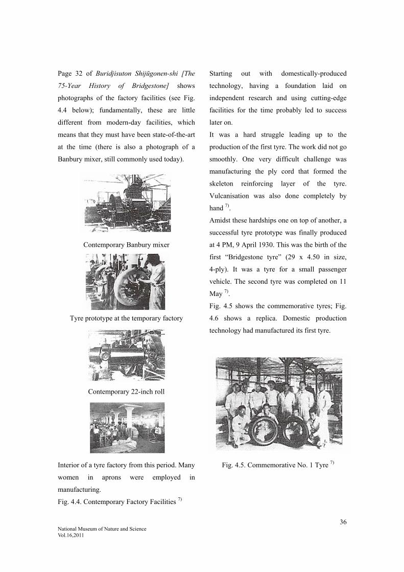
36 National Museum of Nature and Science Vol.16,2011
Page 32 of Buridjisuton Shijūgonen-shi [The
75-Year History of Bridgestone] shows
photographs of the factory facilities (see Fig.
4.4 below); fundamentally, these are little
different from modern-day facilities, which
means that they must have been state-of-the-art
at the time (there is also a photograph of a
Banbury mixer, still commonly used today).
Contemporary Banbury mixer
Tyre prototype at the temporary factory
Contemporary 22-inch roll
Interior of a tyre factory from this period. Many
women in aprons were employed in
manufacturing.
Fig. 4.4. Contemporary Factory Facilities 7)
Starting out with domestically-produced
technology, having a foundation laid on
independent research and using cutting-edge
facilities for the time probably led to success
later on.
It was a hard struggle leading up to the
production of the first tyre. The work did not go
smoothly. One very difficult challenge was
manufacturing the ply cord that formed the
skeleton reinforcing layer of the tyre.
Vulcanisation was also done completely by
hand 7).
Amidst these hardships one on top of another, a
successful tyre prototype was finally produced
at 4 PM, 9 April 1930. This was the birth of the
first “Bridgestone tyre” (29 x 4.50 in size,
4-ply). It was a tyre for a small passenger
vehicle. The second tyre was completed on 11
May 7).
Fig. 4.5 shows the commemorative tyres; Fig.
4.6 shows a replica. Domestic production
technology had manufactured its first tyre.
Fig. 4.5. Commemorative No. 1 Tyre 7)

37 National Museum of Nature and Science Vol.16,2011
Fig. 4.6. Replica of the No. 1 Tyre (BS
Museum Collection) 8)
The initial idea was crucial to starting business
with domestic production technology. The
founder had a huge impact on this.
(2) Embodiment of Ishibashi-ism (Risō to
Dokusō [Ideals and Creation] by Shōjirō
Ishibashi)
According to Shōjirō Ishibashi, while mass
production of Japanese work shoes and rubber
boots was already under way around 1928,
what he wanted to make in the future was
automobile tyres 9), as he felt that tyres were of
utmost importance.
His perception proved to be very sharp indeed,
right from the start 9). Despite Japan having
only a few automobiles at the time, a time
would come when automobiles would be
domestically produced; having five to ten
million cars on the road would mean a
consumption of ten to twenty million tyres.
Accordingly, making purely Japanese tyres and
selling them at affordable prices would be
essential to the development of the automotive
industry.
While still continuing to mass produce
Japanese work shoes and rubber boots,
Ishibashi quietly studied rubber, the main raw
material. He considered all the special
properties of rubber and meditated on the future
of rubber itself 10).
According to Risō to Dokusō [Ideals and
Creation], Shōjirō Ishibashi had breadth of
vision and a sense of duty; when going about
his work, he had insight into technological
development and took the point of view of a
company existing within society.
As discussed above, the three main Japanese
companies made different contributions to early
tyre production; tyres were birthed out of the
early struggle. As war became imminent, it
became harder to import overseas technology;
in the end it seems that there were no
significant differences between the three main
companies in terms of their technology.
4.1.4. Contributions Towards the First
Domestically-Produced Tyre
The three main Japanese companies made the
following contributions towards the first
domestically-produced tyre.
Dunlop (Far East) (now Sumitomo Rubber
Industries, Ltd.)
The Japanese factory (in Kobe) of
Dunlop UK manufactured the first
domestically-produced tyre in 1913.
Dunlop Rubber (Far East) was
established in 1909.
38 National Museum of Nature and Science Vol.16,2011
Yokohama Rubber (now Yokohama Rubber
Company)
Imported technology from Goodrich
(partner). Manufactured the first
domestically-produced cord tyre in
1921. Yokohama Rubber was
established in 1917.
Bridgestone (now Bridgestone Corporation)
Japan’s first tyre produced with
domestic technology in 1930 by the
Japan “Tabi” socks Tire Division,
one year before the founding of
Bridgestone. Bridgestone was
established in 1931.
4.1.5. Toyo Rubber, Founded in Wartime
Establishment of Toyo Rubber
The following account is from Tōyō Gomu
Kōgyō Gojūnen-shi [The Fifty-Year History of
Toyo Tire & Rubber]. 11)
Toyo Tire & Rubber Company was established
under two parent companies, Toyo Rubber
Industrial and Hirano Rubber Manufacturing.
Toyo Rubber Industrial was established in May
1938 by Toyo Boseki for automobile tyre
production as Naigai Saisei Rubber Company
(Naigai Saisei Gomu Kabushikigaisya), but
changed its name in October that year. While
both companies were built up under Toyo
Boseki, they merged and were re-launched as
Toyo Tire & Rubber Company on 1 August
1945, right before the end of the war.
From this description, it seems that Toyo
Rubber was established in 1943. According to
the chronological tables in Taiya no Hanashi
[The Story of the Tyre] 12), “1943: Toyo Tire &
Rubber was established”.
4.1.6. Establishment of Other Tyre
Companies 12)
According to the chronological tables in Taiya
no Hanashi [The Story of the Tyre] (pp.
232-233), the other manufacturers given below
entered the tyre business either during wartime
or post-war.
1944: Dai-Nippon Aircraft Tyres(Dai-Nippon
Kōkūki Taiya) (later Ohtsu Tyre & Rubber)
established
1949: Nitto Tyres(Nittō Taiya) (later Ryoto
Tyres(Ryōtō Taiya)) established
1964: Okamoto Riken enters the tyre business
4.2. The Second Half (Time of Domestic
Production; Wartime Technology,
1930-1945)
From the outbreak of war to the end of the war
(technology through wartime production
expansion and control)
The times grew dark in the 1930s and the
sounds of war could be heard approaching.
Military colours flew high. As Japan entered a
wartime regime, tyre companies set up systems
for supplying military goods. There was a
demand for improved tyre performance in harsh
conditions in areas such as durability. With it
eventually becoming increasingly difficult to
import overseas technology, research began on
domestic production technology and
independent technology began to be developed.
Especially after the Pacific War, everything

39 National Museum of Nature and Science Vol.16,2011
was in military colours; tyre factories were
designated as war factories. Despite initial
emergency wartime procurements, there was a
shortage of raw materials and production
became difficult.
Let us examine how tyre companies handled
such circumstances in the area of technology.
4.2.1. Dunlop Japan (now Sumitomo
Rubber)
During this period, the munitions supply of
Dunlop (Far East), supplied exclusively to the
army and navy, was on the brink of crisis and
certain steps had to be taken to continue
supplies. In 1933, despite ongoing fierce
competition in the tyre market, the decline in
yen exchange meant very few automobile tyre
imports; Japan entered an age of self-reliance
for automobile tyres.
The entry of Dunlop (Far East) entry into
automobile tyre 13) self-reliance around this
time was as follows.
Politically, 1932 was a dark year and there was
a sense of uneasiness about the future. There
was a sudden rising clamour about rejecting
foreign investment; the munitions supply of
Dunlop (Far East), supplied exclusively to the
army and navy, was on the brink of crisis and
certain steps had to be taken to continue
supplies.
Dunlop (Far East) sought to strengthen its ties
with the navy as a means of breaking out of this
deadlock.
It had begun construction on a new factory in
1929 to expand its production and sales
structure. Three years after construction started,
the facility was complete, with the existing
buildings having been renovated.
“The new factory was a four-storey building;
there was an 84-inch open mill in the basement
where rubber compounding was performed for
carbon compounding tread. The basement was
segregated to prevent carbon from spreading.
The ground floor was the mill room, for
measuring chemicals, peptising and mixing
non-black rubber; it was equipped with 84- and
60- inch mills and other rubber kneading rolls,
as well as various calenders.
The first floor was the automobile tyre factory,
equipped with tread extruders and bead
moulding machines, as well as tyre moulding
machines and vulcanisers.” 13)
This facility had basically the same layout as
those of today, other than the compounding
machines using rolls instead of the internal
mixers used today; this indicates that this was a
state-of-the-art facility at the time.
Dunlop (Far East) changed its name to Dunlop
Rubber (Japan) in 1937; on 29 January 1943, it
changed again to Central Rubber Industries. At
this point, aircraft production was held as the
key to victory; increasing efforts were devoted
to this industry, along with the army and navy.
The previous year (1942), aircraft production
had increased to 8,800 machines; in 1943, it
doubled to 17,000.
Central Rubber drove the development of
aircraft tyres, succeeding at this with its own
technology. These were supplied to the army,
but requests were also fielded from the navy.
The 1944 proceeds from aircraft tyre sales
reached ¥5.7 million, making them the

40 National Museum of Nature and Science Vol.16,2011
second-place flagship product second only to
bulletproof tanks, even outselling truck and bus
tyres 28).
The 35th anniversary of Dunlop’s founding fell
in 1944; under a total war regime, Central
Rubber became concealed war plant “Factory
Jinmu 7176” by order of the Munitions
Companies Act 23).
It had achieved the supply of munitions under
an all-out regime despite a shortage of raw
materials.
4.2.2. Yokohama Rubber (now Yokohama
Rubber Company) 14)
The Manchurian Incident in September 1931
led to a rise in demand for military vehicles.
The government and military authorities also
concentrated their efforts on protecting and
developing the domestic automobile industry.
Increased automobile production meant a
sudden rise in demand for tyres. From March
1934, Yokohama Rubber set about expanding
its primary tyre factory.
The most important technical issue was
durability. Tyres had to be developed to meet
the increased demand in order to survive the
fierce competition. Yokohama Rubber’s
technical team devoted itself to increasing tyre
durability. In April 1937, Yokohama changed
its trademark on all its tyres and other products
from “Goodrich” to “Y” for Yokohama and
announced its “New Y Tyre” with a Y on the
tread. This tyre was characterised by a
continuous Y shaped pattern; with its unique,
newly-developed tyre cord (patent granted in
1939), it was more than twice as durable as
existing products and gained a very good
reputation.
Perhaps due to wartime demand, other
companies also made significant improvements
to durability.
4.2.3. Technology Examples
(1) Providing Tyres for Emperor Showa’s Benz
(Grosser Mercedes)and Domestically-Produced
Cars
The Grosser Mercedes was an ultra-luxury
passenger car made for world leaders and
multi-millionaires. With an engine capacity of
7700cc, 150hp output and top speed of
140km/h, it had an enormous engine and was
surprisingly high performance for its time. In
1937, Yokohama Rubber was commissioned by
the Imperial Household Department at the time
to produce tyres to be fitted to the vehicle;
these were completed after one and half a year
of development. These tyres were specially
designed with cloth-inserted sealant pasted
inside the tube so that air would not escape
even if punctured. Their size was 7.50-20 15).
The durability of the tyres fitted to this high
performance vehicle would have been
comparable to those of today. This means that
domestic production technology must have
already reached a considerable level at this time.
This is one example of the level attained by
Japanese engineers having to take creative steps
to achieve things on their own, with it
becoming increasingly difficult to import
overseas technology (see Fig. 4.7) 15).
At this time, significant progress was also made
on passenger vehicle technology and

41 National Museum of Nature and Science Vol.16,2011
domestically-produced passenger vehicles were
also being developed. Fig. 4.8 shows the first
passenger vehicle produced by Toyota (Toyota
Model AA; replica). The tyres were made by
Bridgestone.
In light of the circumstances, it must be said
that Japanese engineers had already mastered
the imported overseas technology and attained
a high level of domestic production technology,
especially in terms of durability. This was the
age of application.
Fig. 4.7. His Imperial Majesty’s Car (from
Yokohama Rubber News) 15)
Fig. 4.8. Toyota Model AA, 1936; Toyota’s
First Passenger Vehicle (Replica) 16)
550-17 Tyres (Bridgestone)
Toyota Automobile Museum Collection
(2) Aircraft Tyres
Demand for military rubber products steadily
increased at Yokohama Rubber since the
outbreak of the Second World War against
Japan in 1941. Since aircraft tyres in particular
had a significant impact on the course of the
war, there was a rush to expand that division 17).
Accordingly, in 1943, the Yokohama factory
fell completely under the supervision and
control of the army and navy 18).
In these circumstances, tyres were also
produced for the Zero fighters.
A Zero fighter discovered in Guam in 1963 is
said to have been fitted with Yokohama tyres.
Having gone through 20 years of typhoons, the
aircraft was damaged beyond recognition, but
the tyres were still in a useable state 17). This
indicates the high durability capable through
independently-developed Japanese technology
(see Fig. 4.9).
Fig. 4.9. Zero Fighter Tyre 17)
Held by Yokohama Rubber Company
Hiratsuka Factory
(made in May 2006)
Emperor Showa’s Benz (1935-1955) 1935 model (7700cc, 150hp, 140km/h)Benz Museum, donated by the Imperial Household Agency Fitted with Yokohama tyres (made in 1938)

42 National Museum of Nature and Science Vol.16,2011
4.2.4. Bridgestone 19)
(1) Wartime Regime
A directive from the Minister of Commerce and
Industry in January 1939 prohibited the
manufacture of passenger vehicles other than
for military use; the production of small trucks
was also mostly prohibited. Accordingly,
production of automobile tyres was also limited
to ordinary trucks, most of which were military
vehicles 19).
Meanwhile, full-scale production and supply of
aircraft tyres started in 1939. As the war
intensified, production rapidly increased. The
annual production number of around 3,000 in
1939 is estimated to have grown around 60
times to 176,000 in 1944.
Bridgestone also progressed into wheel
manufacturing as part of its wartime
aircraft-related operations. This corresponds
with an order from the army in 1942 to supply
combined wheels and tyres for aircraft.
(2) Tyres for the “Falcon” Fighter
While tyres for the Hayabusa “Falcon” fighter
are mentioned in the company history (Fig.
4.10), an actual tyre for the Falcon is held in the
Bridgestone Museum (see Fig. 4.11). It is in
good shape with hardly any deterioration 8).
Tyre for the “Falcon” fighter ‘560 x 190’
(manufactured in March 1942)
Fig. 4.10. Tyre for the “Falcon” Fighter 20)
Buridjisuton 75-nen-shi [The 75-Year History
of Bridgestone]
Fig. 4.11. Tyre for the “Falcon” Fighter 8)
Size: 570-190; made in February 1944 by
Nippon Tire Company
Bridgestone Museum Collection
While wartime technology was
munitions-focused, it had come a long way on
its own efforts. On 20 February 1942, the
company changed its name to Nippon Tire
Company at a request from military authorities
to amend the English name. The Bridgestone

43 National Museum of Nature and Science Vol.16,2011
Tire company name disappeared for ten years,
until 25 February 1951.
(3) Level of Aircraft Tyre Technology at the
Time
Taiya no Hanashi [The Story of the Tyre], by
Rokurō Hattori, records the following regarding
wartime development of aircraft tyres.
“Looking back, the time before and during the
war was a time of suffering for Japanese
aircraft tyres; many aircraft designers thought
only of flying faster and further – tyres and
other things that weren’t used in the air were
nothing more than a necessary evil. Tyre
manufacturers were requested to produce a tyre
that could support such and such a weight
within certain dimensions. … Such poor design
and underdeveloped manufacturing technology
resulted in frequent serious accidents from tyres
bursting.
However, while it had seemed like every effort
had been in vain, light began to dawn on
improvements in tyre durability. Various
elements in tyre design somehow made it
possible to estimate tyre durability.” 21)
This account has some credibility, as these are
the words of someone at the site of
development (Hattori was a former Bridgestone
engineer, employed in naval aircraft design
during the war).
By the end of the war, a reasonable level of
durability had presumably been attained.
4.2.5. Toyo Tire & Rubber 22)
According to Tōyō Gomu Kōgyō 50-nen-shi
[The 50-Year History of Toyo Tire & Rubber]
the following circumstances occurred.
“At the time [around 1941; author note], tyre
production at Toyo Rubber Industrial
[predecessor organisation; author note] was still
in its infancy. As the war intensified, ensuring
tyres for the military became top priority and
the company had to respond.
Related to this, trucks manufactured by
Kawasaki Rolling Stock Manufacturing
Company (now Kawasaki Heavy Industries)
were fitted with tyres by Toyo Rubber
Industrial and other companies and given a
five-day road test. The route went out of Kobe
from Okayama to Tottori; while it was a
rigorous test for the time, the results
demonstrated that Toyo tyres were more
durable than those of other companies. With
these outstanding results, Toyo Rubber
Industrial products were highly rated by
Kawasaki Rolling Stock Manufacturing
Company; Toyo then received its first order for
military truck tyres and tubes.”
This account indicates that highly durable tyres
had been developed by Toyo Tire & Rubber as
well.
From the above, it can be considered that there
was a rising level of interest in tyre durability
as a basic performance factor from around this
time.
4.3. Industry Response to the Wartime
Regime
At this time, there was a form of technical
cooperation in the industry.
44 National Museum of Nature and Science Vol.16,2011
According to Bridgestone, in January 1938,
Dunlop Rubber Company (Japan), Yokohama
Rubber and Nippon Tire (Bridgestone; author
note) anticipated the expected regulation of
rubber distribution in that coming July and
established the Japan Automobile Tyre Industry
Association(Nihon Jidōsha Taiya Kōgyō
Kumiai), gaining government approval in April.
The Association carried out business in
cooperation with the Japan Tyre
Association(Nihon Taiya Kyōkai), but when
that Association dissolved in March 1939, the
Japan Automobile Tyre Industry Association
inherited all of its operations. 20)
The Japan Automobile Tyre Industry
Association dissolved after ceding its
operations to the Rubber Control
Association(Gomu Tōsēkai) launched in
January 1943.
4.3.1. Wartime Technology
By the end of the war, the aforementioned
Control Association was engaging in operations
(1944).
According to Nihon Gomu Kōgyō-shi [The
History of the Japanese Rubber Industry], the
following circumstances were in place.
The aim of the Rubber Control Association was
to “provide comprehensive regulation and
administration of operations related to
marketing as well as production and sales of
rubber products (hereinafter as Rubber
Production) in order to provide an advanced
state defence system and to collaborate in the
drafting and execution of state policies related
to Rubber Production” (Articles of
Incorporation, Article 1). The Association was
to carry out various operations in order to
achieve this aim.
These operations can be divided into two broad
categories: directly and indirectly taking part in
government planning and cooperating with
government policy execution. Above all, the
basic mission of the Control Association was to
cooperate with the execution of government
policies.
(i) Taking part in government planning
(ii) Cooperating with regulation execution
There were seven aspects to cooperating with
regulation execution: 1. production regulation;
2. regulation of supply of raw materials; 3.
regulation of product distribution; 4. price
regulation; 5. labour regulation; 6. technology
regulation; 7. curtailment of business
operations.
Of these, the most important task was to do
with technology regulation: improving the
technology of the rubber industry and
improving and promoting efficiency in the
industry in order to increase production during
wartime.
The Rubber Control Association designated
members, provided mediation and established
technical committees in addition to its
technology division for the purposes of
researching and improving technology as well
as exchange and disclosure. It had a product
subcommittee to ensure technology regulation.
In April 1944, nine articles of regulations on
technology exchange and disclosure were
drawn up; these stipulated specific agreements
regarding technology exchange and disclosure,

45 National Museum of Nature and Science Vol.16,2011
as well as an accompanying compensation
system. Decisions were made to meet the
demands for increased production 24).
Accounts such as the following state that
effective technological advances were made in
the field of rubber.
4.3.2. Specific Advances in Rubber
Technology 25)
According to Nihon Gomu Kōgyō-shi [The
History of the Japanese Rubber Industry], as
the Pacific War intensified, there was a
shortage of raw materials accompanied by a
decline in the quality of rubber products. With
an increasing demand to ensure rubber products
high in both quantity and quality, the
technology division of the Rubber Control
Association planned and implemented an open
exchange for superior technology.
This rapidly lifted the overall level of
technology in the rubber industry, making it
very significant in the history of rubber
technology. In other words, it would not be
exaggerating to say that this rise in the level of
technology provided the basis for the rapid
restoration and development of the rubber
industry in Japan after the war 25).
The following is based on research on various
raw materials.
1. Raw materials
(1)Natural rubber; (2) latex; (3) reclaimed
rubber
2. Secondary materials
(1)Domestic production of carbon black
(reinforcing agent)
There were successive instances of
domestic production of carbon black
(2) Fibres
Despite a temporary ease of access to
resources in the south following the onset
of the Pacific War, fibres were still in short
supply.
In 1942, a directive was issued to produce
reinforced rayon and Toyobo and other
companies entered an era of finding practical
applications for reinforced rayon. It was found
that 20-30% rayon cord was suitable for use in
automobile tyres. Yokohama Rubber, Nippon
Tire and Central Rubber each joined forces
with rayon companies to produce prototypes
and performed running tests on these fitted to
trucks and passenger vehicles, reporting very
good results. In 1943, the technology division
of the newly-established Rayon Control
Association(Jinken Tōsēkai) proposed and
established provisional standards for reinforced
rayon for use in tyre cord. According to a report
by Automobile Division 3 of the administration
bureau of the Ministry of Railways, which had
carried out practical testing for a year from
August 1942 to July 1943, “of the 12 tyres, 6
exceeded the life expectancy of the existing
Egyptian cotton cord tyres (24,141km in 1942),
2 by 90% or more, 3 by 80% or more and 1 by
68%.” This was a good result, acknowledging
that the average number of kilometres of
25,228 was better than the ordinary product 27).
As indicated above, it was an age of
regulations; technology advanced rapidly as
companies worked together, sharing technology

46 National Museum of Nature and Science Vol.16,2011
for the sake of development. There are many
accounts regarding the outcome of this
technology disclosure. Technology develops
when a country has to get by on its own
technology.
Taiya no Hanashi [The Story of the Tyre] 26) by
Rokurō Hattori has the following account
regarding cotton tyre cord technology.
“Since spun yarn transmits force by means of
entwined short fibres, the longer raw cotton
fibres are, the better quality they are. Raw
cotton was graded by an expert who would take
a pinch of it between the thumb and index
finger of both hands and tear it several times,
then lay the pieces out on black velvet to form a
kind of fibre length spectrum to judge its
quality.
Later on, to maintain strength, low stretch
processing was carried out to prevent any
excess stretching. This was a method of
winding which provided a strong tensile
strength in the winding process; adding water
and using fixative would prevent the yarn from
stretching back. This process significantly
improved the quality of cotton cord. During the
Second World War, there were concerns about
variation in the lifespan of the company’s
[Nippon Tire, Bridgestone; author note] aircraft
tyres, but the introduction of Yokohama
Rubber’s low stretch production method
through technology disclosure led by the navy
greatly improved the lifespan of the tyres and
reduced the variation. This is a true story I
heard from my immediate supervisor.”
This actually also shows the effects of the
technology control associations.
This technology is thought to have been applied
to aircraft such as the “Zero” and the “Falcon”.
As mentioned previously, the Nippon Tire
(Bridgestone) tyre on the Falcon fighter and the
Yokohama Rubber tyre on the Zero fighter
show little outward sign of deterioration,
indicating the high level of technology at the
time.
This is surely the result of incorporating
improved product quality through technology
disclosure.
4.4. Summary
As seen above, the period spanning the Taisho
Period to the end of the war can be divided two
ways.
1. The age of Japanese factories for overseas
tyre companies or introducing overseas
technology (Dunlop, Yokohama)
These companies imported overseas
technology, but also studied it for
themselves and went on to develop their own
technology.
2. The age of starting independent technology
from the beginning (Bridgestone, Toyo)
As the Pacific War era approached, other
countries started to be boycotted and Japanese
companies had to get by on their own
technology. There was little difference between
1 and 2 at this point; both rapidly advanced in
performance and production technology. The
technology evidently reached a very high level
during the war, as they also had to produce all
of their own technology despite an extreme

47 National Museum of Nature and Science Vol.16,2011
shortage of raw materials and expand their
adaptive abilities to produce goods for the
military, with rigorous usage conditions. The
level of durability would have increased rapidly
during this period.
Cited references:
1) Sumitomo Gomu Hachijū-nen-shi [The Eighty-Year History of Sumitomo Rubber], Sumitomo Rubber Industries,
Ltd., October 1989, p. 31.
2) Sumitomo Gomu Hachijū-nen-shi [The Eighty-Year History of Sumitomo Rubber], Sumitomo Rubber Industries,
Ltd., October 1989, p. 18.
3) Sumitomo Gomu Hyakunen-shi [Hundred-Year History of Sumitomo Rubber], Sumitomo Rubber Industries, Ltd.,
October 1989, p. 39, on which the following is cited. Nihon Gomu Kōgyō-shi [The History of the Japanese Rubber
Industry], Vol. 1, The Japan Rubber Manufacturers Association, ed., 1 November 1969, pp. 203-204.
4) Sumitomo Gomu Hyakunen-shi [Hundred-year History of Sumitomo Rubber], Sumitomo Rubber Industries, Ltd.,
December 2009, p. 44.
5) Sumitomo Gomu Hyakunen-shi [Hundred-year History of Sumitomo Rubber], Sumitomo Rubber Industries, Ltd.,
December 2009, see preface.
6) Yokohama Gomu Sōritsu 50-Shūnen [Yokohama Rubber 50-Year Jubilee], Yokohama Rubber Company, October
1967, p. 22. A description of this cord tyre also appears in Sumitomo Gomu Hachijū-nen-shi [The Eighty-Year
History of Sumitomo Rubber], p. 33.
7) Buridjisuton Nanajūgo-nen-shi [The 75-Year History of Bridgestone], Bridgestone Corporation, May 2008, pp.
31-33.
8) Bridgestone Today Museum Collection, 3-1-1 Ogawa Higashimachi, Kodaira-shi, Tokyo
9) Ishibashi, Shōjirō: Risō to Dokusō [Ideals and Creation], Diamond, December 1969, p. 27.
10) Ishibashi, Shōjirō: Risō to Dokusō [Ideals and Creation], Diamond, December 1969, p. 152.
11) Tōyō Gomu Kōgyō 50-nen-shi [The 50-Year History of Toyo Tire & Rubber], Toyo Tire & Rubber Company, 21
March 1996, p. 65.
12) Hattori, Rokurō: Taiya no Hanashi [The Story of the Tyre], Taiseisha, June 1992, pp. 232-233.
13) Sumitomo Gomu Hachijū-nen-shi [The Eighty-Year History of Sumitomo Rubber], Sumitomo Rubber Industries,
Ltd., October 1989, p. 89.
14)Yokohama Gomu Sōritsu 50-Shūnen [Yokohama Rubber 50-Year Jubilee], Yokohama Rubber Company, October
1967, p. 27.
15) “His Imperial Majesty’s Car”, Yokohama Rubber News, No. 34, October 1972, p. 10.
16) Toyota Automobile Museum Collection, 41-100 Yokomichi, Nagakute, Aichi. Originally released as “Toyoda”
with the voiced sound indicators included on the final character in the Japanese script. Changed to “Toyota”

48 National Museum of Nature and Science Vol.16,2011
without the voiced sound indicators in October 1936. (Discussion with Toyota Automobile Museum.)
17)Yokohama Gomu Sōritsu 50-Shūnen [Yokohama Rubber 50-Year Jubilee], Yokohama Rubber Company, October
1967, p. 31.
18) 80 Shūnen Kinen We Tokubetsu-gō [80-Year Anniversary We Special Edition], Yokohama Rubber Company,
October 1997, p. 53.
19) Buridjisuton Nanajūgo-nen-shi [The 75-Year History of Bridgestone], Bridgestone Corporation, May 2008, pp.
55-56.
20) Buridjisuton Nanajūgo-nen-shi [The 75-Year History of Bridgestone], Bridgestone Corporation, May 2008, p. 57.
21) Hattori, Rokurō: Taiya no Hanashi [The Story of the Tyre], Taiseisha, June 1992, p. 23.
22) Tōyō Gomu Kōgyō 50-nen-shi [The 50-Year History of Toyo Tire & Rubber], Toyo Tire & Rubber Company, 21
March 1996, p. 70.
23) Sumitomo Gomu Hachijū-nen-shi [The Eighty-Year History of Sumitomo Rubber], Sumitomo Rubber Industries,
Ltd., October 1989, pp. 123-124.
24) Nihon Gomu Kōgyō-shi [The History of the Japanese Rubber Industry], Vol. 1, The Japan Rubber Manufacturers
Association, ed., 1 November 1969, pp. 317-320.
25) Nihon Gomu Kōgyō-shi [The History of the Japanese Rubber Industry], Vol. 1, The Japan Rubber Manufacturers
Association, ed., 1 November 1969, p. 328.
26) Hattori, Rokurō: Taiya no Hanashi [The Story of the Tyre], Taiseisha, June 1992, pp. 108-109.
27) Nihon Gomu Kōgyō-shi [The History of the Japanese Rubber Industry], Vol. 1, The Japan Rubber Manufacturers
Association, ed., 1 November 1969, p. 332.
28) Sumitomo Gomu Hachijū-nen-shi [The Eighty-Year History of Sumitomo Rubber], Sumitomo Rubber Industries,
Ltd., October 1989, pp. 121-122.

49 National Museum of Nature and Science Vol.16,2011
5. Stage of Maturity: The Age of Motorisation
5.1. Stage 1: Technology in the Posr-War
Rebuilding Period
5.1.1. The Age of New Materials – the Rise
of the Post-War Motorisation Age
(1) Post-War Situation
The recovery from the chaotic post-war
aftermath 1) (the age of new materials) was as
follows.
Although the rubber industry had taken a major
hit from war damage, its recovery was
comparatively quick, given the state of other
post-war industries. Reasons for this included
the fact that the industry had had training in
collective control and had taken to collective
behaviour before and during the war, the fact
that raw rubber and fibres that had been held by
the army and navy during the war were released
into the private sector at the end of the war in
greater amounts than had been expected during
the war, and the fact that military demand could
be converted to private demand relatively
simply; but the main reason was a prompt and
relevant directive to all rubber factories in the
country from the Rubber Control Association
based on government policy at the end of
August 1945, outlining “matters on provisional
measures on handling the new situation in the
rubber industry” 1).
To put it simply, this directive put an
immediate end to the exclusive production of
military goods and allowed private sector
production to continue or increase.
This period was the entry point into the age of
motorisation (see Fig. 5.1) 2); later, as society
suddenly became motorised, major changes
happened with tyres as well. The distinguishing
characteristic of this period was the appearance
of new materials.
Fig. 5.1. Ownership of Four-Wheeled Vehicles
in Japan (unit: 10,000 vehicles) 2)
(Sekai Jidōsha Tōkei [World Motor Vehicle
Statistics], Vol. 6, 2007)
(2) The Appearance of New Materials
For the Japanese tyre industry, this period was
a time of importing and learning overseas
technology once the country reopened after the
war.
The greatest change was the introduction of
new materials. This included the transition in
reinforcing material from cotton to synthetic
fibres such as rayon and nylon and the
emergence of synthetic rubber as a raw
polymer. Consequently, difficulty arose in this
period in adopting new materials without
changing bias processing machines. There are
1928 1950 1970 1990 2005

50 National Museum of Nature and Science Vol.16,2011
tales of hard times learning to use nylon and
SBR. In other words, this period was a time of
changes in raw materials.
(3) Reinforcing material (tyre cord)
(i) Changes in tyre cord
In modern terms, tyres are made of fibre
reinforced rubber (FRR). This structure was
implemented because tyres are pressure vessels.
Tyres are a kind of balloon; natural rubber on
its own cannot counteract the internal pressure
and needs to be wrapped in a strong,
non-stretch material. It needs reinforcing fibre
to do that. With internal pressure in the tyre,
tension is applied to the tyre cord. Actual tyres
are wrapped in reinforcing materials such as
fibre and steel cords. The tension applied to the
reinforcing layer is determined by the balance
between internal pressure and external shape.
Consequently, the tension applied to the cord
on a turning tyre fluctuates. Therefore, tyre
cord must be rated not only on strength and
breaking elongation, but also from the
perspective of fatigue, deterioration and
adhesion between the rubber and the cord.
Rayon started to be used in the United States
from around the 1940s; nylon appeared in the
1950s and gradually grew in popularity, while
cheaper polyester also began to be used. Rayon
cord was replaced by nylon in post-war Japan.
Looking at the volume of consumption, as
shown in Fig. 5.2, we see that nylon took over
as the main cord fibre in the mid-1960s.
Nylon’s replacement of rayon in the United
States is thought to be around 10 years earlier.
This means that the tyres on the B-29 bombers
that bombed Kyushu towards the end of the war
contained nylon, something previously not seen
in Japan. These were ideal for aircraft tyres in
terms of impact resistance and fatigue
resistance and accordingly were already in use
during the war 5).
Fig. 5.2. Post-War Changes in Tyre Cord 10)
(ii) Details on tyre cord 4)
1) Cotton cord
Until regenerated and synthetic fibres appeared,
cotton was the only fibre with the adequate
performance, cost, availability, and other
factors to be used as an industrial fibre. Most
tyre cord was also cotton. Since cotton has
short fibres, it has to go through a spinning
process that pulls and twists the fibres together.
2) Rayon cord
Fibre made by chemically extracting and
re-forming natural fibres (cellulose). The tyre
cord is made using the viscose method, in
which a pulp of wood or other material is
treated with caustic soda, dissolved in carbon
disulphide and aged to form a sticky liquid
called viscose, which is pushed through a
nozzle to form threads. Increasingly higher
quality tyre cords emerged, while and rayon
Rayon
Nylon
(Year)
Usa
ge v
olum
e (1
,000
t)

51 National Museum of Nature and Science Vol.16,2011
and reinforced rayon have even recently been
rated as having no noise, vibration or flat spots
(a phenomenon in which the part of a tyre in
contact with the road changes shape after the
car has stopped and cooled) when production
conditions are good and have been used in high
performance tyres. Following the appearance of
radial tyres, it continued to be used in the
carcasses of high performance tyres, mainly in
Europe. In Japan, there has not been much
success with stable fibres, made by cutting spun
thread into short fibres and twisting them.
3) Nylon cord
Synthetic nylon tyre cord appeared on the
market in Japan around 1950. This was made
by melt spinning a dissolved liquid. As it was
highly stretchy in that state, it had to undergo a
stretching operation to align the crystals and
make it stronger; the stretch also had to be
within an appropriate range.
Most tyres at the time were for trucks and buses,
but nylon matched that need. Nylon is still used
today in bias tyres for heavy services such as
trucks, buses, construction machinery and
aircraft. Nylon is stronger than rayon and does
not lose its strength when wet like rayon does.
However, nylon shrinks in the heat and requires
a process of cooling while still inflated after
vulcanisation.
Later, reinforcing layers for passenger vehicle
tyres were made of combinations of steel cord
and polyester. With that change, nylon
appeared to have lost its main function;
however, an increasing number of tyres had
another layer of reinforcing material in the
circumferential direction above the belt and
nylon was often used as reinforcement for this
layer, thereby winning back a major field of use
for it to date. This layer heats up while the
vehicle is in operation and forms another layer
over the steel belt due to thermal contraction,
thereby improving high speed durability. Nylon
clearly exemplifies the rise and fall of a
material in a very short time.
(4) Organic fibre tyre cord adhesion
(i) RFL adhesive
RFL is a fibre adhesive made up of a
combination of resorcinol (R), formaldehyde
(F) and latex (L). In the 1940s, Church and
Manny et al. discovered that a liquid adhesive
made by adding resorcinol formaldehyde resin
to an aqueous solution of rubber latex had
superior adhesion properties. For the next half
century, RFL has been the main adhesive used
on fibres such as rayon, nylon, polyester,
aramid and glass fibre.
The adhesion mechanism is thought to be as
shown in Fig. 5.3. The figure shows nylon on
the left, rubber on the right and resorcinol and
formaldehyde simply in between, causing a
three-dimensional resinification reaction. The
main cause of adhesion is the resin
fundamentally forming a secondary bond
(hydrogen bond) rather than a primary bond
(chemical bond) with the nylon and the rubber.
As shown in the figure, a resinification reaction
occurs in the resorcinol between the rubber and
the nylon, producing a resin between the rubber
and nylon. The adhesive is produced along with
the resinification reaction between the rubber
and the nylon.

52 National Museum of Nature and Science Vol.16,2011
RFL resin is a significant invention that can be
used generically on most fibres. It also made a
very significant contribution to the tyre
industry.
Fig. 5.3. RFL Adhesion Mechanism between
Nylon and Rubber 8)
(5) Changes in Cord by Companies
According to the history of Bridgestone,
changes in cord happened as follows. By the
1950s, the United States was mostly using
rayon instead of cotton; Bridgestone also
recommended a change to rayon due to its low
cost. This change took place rapidly, as by
1952, rayon was being used in 80% of their
tyres.
Later, there was a change to nylon cord
(initially for aircraft tyres); this change also
happened quickly, with sales commencing in
1959. Major changes were happening with cord
at this time 18).
Yokohama Rubber Company developed a
rayon tyre in 1950. By 1955, it had
domestically produced an aircraft tyre with
nylon cord in it 13).
Toyo Rubber switched to rayon in the same
period. According to its company history,
various tyre manufacturers had started using
rayon cord by 1951, while Toyo itself
completed a dipping machine, put separation
countermeasures in place and put rayon tyres
on the market in February 1952 12).
Research on nylon tyres was carried out in
earnest from the spring of 1954; from
December 1958, they were marketed all over
the country for trucks and buses 12).
As outlined above, major changes in cord
happened at around the same time.
(6) Composition of Rubber Compounds
The rubber used in tyres is a compound of
various compounding agents. In other words, it
is basically a compound of natural rubber,
styrene-butadiene rubber (SBR) or other
synthetic rubber (raw rubber) with reinforcing
agents such as carbon black added to it, as well
as compounding agents such as vulcanizing
agents (to cause a cross-linking reaction to
produce elastic rubber) and anti-ageing agents
(for durability) mixed in. By changing the ratio
of the raw rubber, reinforcing agents and
vulcanizing agents, these compounds can form
the required rubber; in other words, various
kinds of rubber from hard to soft can be
produced for use in various components. The
greater the capacity, the greater the impact on
the properties of the rubber; natural rubber
RFL resin (adhesive layer)
Nylon layer Rubber layer
Hydrogen bond
Hydrogen bond
Cross-linkingpoint
Cross-linkingpoint

53 National Museum of Nature and Science Vol.16,2011
(polymer) has the greatest impact.
(i) Adoption of synthetic rubber (natural
polymers)
Right before the Second World War, the
Japanese government noted the importance of
synthetic rubber as a military resource. In 1938,
it set up a 10-year plan to establish a synthetic
rubber industry; in 1941, it issued the Organic
Synthesis Businesses Act(Yūki Gōsē Jigyō Hō)
to protect and develop it 16).
Research on the industrialisation of butadiene
rubber in Japan grew more prolific as the war
started. Through its occupation of southern
territories, Japan was able to secure sources of
natural rubber, which meant that SBR was no
longer necessary. Focus shifted to the
production of oil resistant NBR (acrylonitrile
butadiene rubber) 16).
As the war ended, the Allied Forces
Headquarters prohibited the production of
synthetic rubber, providing a minor setback.
However, from around 1950, the Ministry of
International Trade and Industry, The Japan
Rubber Manufacturers Association and the
private sector began discussing the need to
domestically produce synthetic rubber once
more. Later, as the plans for the petrochemical
industry began to take shape in Japan, a plan
was proposed around 1955 requiring synthetic
rubber for B-B fraction in oil-cracked gas
rather than from alcohol. In 1957, the Act on
Special Measures for Synthetic Rubber
Production Businesses(Gōsē Gomu Seizō Jigyō
Tokubetsu Sochi Hō) was issued and Japan
Synthetic Rubber established through ¥1 billion
of government funding and ¥2.5 billion in
capital. Technology was imported from
Goodyear in the United States and a factory
started operating in Yokkaichi in 1960,
producing 45,000 tons of SBR per year 11) 16).
Meanwhile, “Nippon Zeon imported
technology from Goodrich Chemical in the
United States and started operating a factory in
Kawasaki in 1959, producing 8,500 tons per
year of mainly special non-SBR rubber, such as
NBR and high styrene rubber. Production of
SBR started in 1962, with production
expanding to a total of 30,000 tons, including
10,000 tons of SBR and 20,000 tons of NBR
and other special rubber. In 1965, a second
plant opened in Tokuyama, producing a total of
45,000 tons per year, including 20,000 tons of
SBR and 15,000 tons of BR. It supplied its own
raw butadiene using its own extractive
distillation methods.” 16)
The change from natural rubber to SBR
involved a struggle with reduced tack. In the
moulding process during manufacture, tyres are
moulded from layers of unvulcanised rubber,
which requires tack (stickiness). Since SBR is
less tacky than natural rubber, it was more
difficult to mould. The invention of tackifiers in
the United States solved this issue and paved
the way for later widespread use 17).
Changes were taking place in compounding
technology, with large amounts of fillers and
oils being compounded as well as SBR.
When Japan Synthetic Rubber Company was
established, the majority of the members of the
Bridgestone Research Division Tokyo Office
transferred there and successfully produced
SBR. Meanwhile, the “Bridgestone catalyst”

54 National Museum of Nature and Science Vol.16,2011
was perfected for cis polybutadiene rubber and
patented in 1959; this catalyst provided a
successful cis polybutadiene compound. In
1963 a pilot plant started operation; the main
factory was completed in 1964 and started
operating in 1965. This was Japan’s first cis
polybutadiene and was rated very highly; the
technology was exported many times 15).
One account on the introduction of synthetic
rubber tyres states that “the Passenger Vehicle
Tyre Division perfected the country’s first
synthetic rubber tyre, throwing new light onto
the devotion to natural rubber and greatly
improving the durability of truck and bus tyres
by using reinforced rayon.” 13) New product
development, which had seemed to stall for a
while in the turbulent times following the war,
gradually revived from around the time that
rubber regulation ended (1950).
Yokohama Rubber Company announced a
synthetic rubber tyre in 1957 14).
Fig. 5.4. Transitions in Raw Rubber Volumes
(Domestic Production) in Post-War
(1953-1968) Japan 3) (MT = metric ton)
The post-war raw rubber situation is shown in
Fig. 5.4. It is clear how rapid the changes in
raw materials were during this period. From
around 1960 in particular, there was a rapid
increase in the volume of domestically
produced synthetic rubber used.
Looking at the above post-war initiatives in
synthetic rubber, the two things that later
undergirded Japan’s tyre industry were the fact
that some knowledge and experience in
compounding existed before the war and the
fact that even though Japan imported American
technology after the war, it had the ability to
develop its own technology in a coordinated
fashion.
Pre-war compounding research is thought to
have aided the progress of post-war polymer
compounding technology. In other words, past
experience made a significant contribution.
This was one type of technology import in
modern Japan.
As shown in the figure above, the demand for
rubber grew rapidly with the rapid spread of
motorisation up until around 1970. There was a
rapid increase in domestically produced
synthetic rubber from around 1960 in particular.
Around half of this synthetic rubber was used
in tyres.
(ii) Carbon Black
Carbon black was produced by a US company
in the 1870s. Later, the channel process of
making it from natural gas was devised and
became the main method used. During the
Second World War, the furnace process
emerged along with synthetic rubber; the oil
Synthetic rubber (domestic production)
Synthetic rubber (imported)
Natural rubber

55 National Museum of Nature and Science Vol.16,2011
furnace method used today, using heavy liquid
oil instead of natural gas, became the main
method used.
Carbon black is a type of soot found in the
early 20th century to have a reinforcing effect
on rubber. It became an essential reinforcing
agent because it rapidly improves the strength
of the rubber when added as such.
With the appearance of synthetic rubber,
furnace black became the carbon black used
due to its high reinforcing properties.
While carbon black is a stratified substance
composed of carbon, it is particulate in form;
the surface of the particles react with the
polymers, causing a reinforcing effect (see Fig.
5.5). The larger the size of the particles, the
smaller the surface area and the lesser the
reinforcing effect. However, the smaller the
particles, the greater the surface area and the
greater the reinforcing effect. During this
period, carbon particles were made smaller in
size to increase the reinforcing effect.
Electron micrograph of carbon black (provided
by Mitsubishi Chemical Corporation)
Carbon black structure (provided by Mitsubishi
Chemical Corporation)
Fig. 5.5. Form of Carbon Black 6)
Properties of Carbon Black
Particle Size Large Small
Breaking
strength
Low High
Hardness Low High
Wear resistance Low High
Heat build-up
(lower is better)
Low High
As an overall trend, small-particle carbon black
is used on tread, the area of the tyre in contact
with the road, where wear resistance is
important. Large-particle carbon black is used
in the rubber covering the internal cord in order
to reduce the heat build-up.
Fig. 5.6 shows how tyre production volumes
have increased. As seen in this figure,
production increased by 50 times in a 30 year
period from 1955. The figure shows a rapid
Basic properties of carbon black
(A) Layer surface(steel surface)
(B) Crystallite
(C) Particlesize
Structure
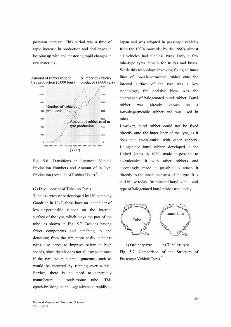
56 National Museum of Nature and Science Vol.16,2011
post-war increase. This period was a time of
rapid increase in production and challenges in
keeping up with and mastering rapid changes in
raw materials.
Fig. 5.6. Transitions in Japanese Vehicle
Production Numbers and Amount of in Tyre
Production (Amount of Rubber Used) 9)
(7) Development of Tubeless Tyres
Tubeless tyres were developed by US company
Goodrich in 1947; these have an inner liner of
low-air-permeable rubber on the internal
surface of the tyre, which plays the part of the
tube, as shown in Fig. 5.7. Besides having
fewer components and attaching to and
detaching from the rim more easily, tubeless
tyres also serve to improve safety at high
speeds, since the air does not all escape at once
if the tyre incurs a small puncture, such as
would be incurred by running over a nail.
Further, there is no need to separately
manufacture a troublesome tube. This
epoch-breaking technology advanced rapidly to
Japan and was adopted in passenger vehicles
from the 1970s onwards; by the 1990s, almost
all vehicles had tubeless tyres. Only a few
tube-type tyres remain for trucks and buses.
While this technology involving fixing an inner
liner of low-air-permeable rubber onto the
internal surface of the tyre was a key
technology, the decisive blow was the
emergence of halogenated butyl rubber. Butyl
rubber was already known as a
low-air-permeable rubber and was used in
tubes.
However, butyl rubber could not be fixed
directly onto the inner liner of the tyre, as it
does not co-vulcanise with other rubbers.
Halogenated butyl rubber, developed in the
United States in 1960, made it possible to
co-vulcanize it with other rubbers and
accordingly made it possible to attach it
directly to the inner liner area of the tyre. It is
still in use today. Brominated butyl is the usual
type of halogenated butyl rubber used today.
a) Ordinary tyre b) Tubeless tyre
Fig. 5.7. Comparison of the Structure of
Passenger Vehicle Tyres 7)
Amount of rubber used in tyre production (1,000 tons)
Number of vehicles produced (1,000 cars)
Number of vehicles produced
Amount of rubber used in tyre production
(Year)
Tube
Inner liner

57 National Museum of Nature and Science Vol.16,2011
Cited references:
1) Yokohama Gomu 40-nen-shi [The 40-Year History of Yokohama Rubber], Yokohama Rubber Co., Ltd., January
1959, p. 398.
2) Buridjisuton Nanajūgo-nen-shi [The 75-Year History of Bridgestone], Bridgestone Corporation, May 2008, p. 30.
(Source) Sekai Jidōsha Tōkei [World Motor Vehicle Statistics], Vol. 6, 2007
3) Data from Gomu Gijutsu Gaidobukku [Rubber Technology Guidebook], Nikkan Kogyo Shimbun, Ltd., October
1973, p. 26.
4) Hattori, Rokurō: Taiya no Hanashi [The Story of the Tyre], Taiseisha, June 1992, pp. 106-112.
5) Hattori, Rokurō: Taiya no Hanashi [The Story of the Tyre], Taiseisha, June 1992, p. 24.
6)Gomu Gijutsu Nyūmon [Introduction to Rubber Technology], The Society of Rubber Science and Technology,
Japan, ed., October 2005, Maruzen, p. 52.
7) Hirata, Yasushi: Journal of the Society of Rubber Science and Technology, Japan, Vol. 68, 25, 1995.
8) Matsui, Junichi; Toki,Masamichi; Shimizu,Hisao: Journal of the Adhesion Society of Japan, Vol. 8, No. 1, p. 26,
1972.
D. I. James et al.: Trans. Proc. Inst. Rubber Ind., Vol.39, No. 3, p. 103, 1963.
Written based on these documents.
9) Material from Japan Automobile Tyre Manufacturers Association (from Nihon no Taiya Sangyō 2007 [Japan’s
Tyre Industry 2007]).
10) Figure based on Gomu Kōgyō Binran [Rubber Industry Handbook], fourth edition, The Society of Rubber
Science and Technology, Japan, ed., January 1994, p. 549.
11) Buridjisuton Nanajūgo-nen-shi [The 75-Year History of Bridgestone], Bridgestone Corporation, May 2008, p.
105.
12) Tōyō Gomu Kōgyō 50-nen-shi [The 50-Year History of Toyo Tire & Rubber], Toyo Tire & Rubber Company,
March 1996, rayon p. 99, nylon p. 117.
13) Sōritsu 50-Shūnen Yokohama Gomu [50-Year Jubilee of Yokohama Rubber], Yokohama Rubber Company,
October 1967, p. 38.
14) 80 Shūnen Kinen We Tokubetsu-gō [80-Year Anniversary We Special Edition], Yokohama Rubber Company,
October 1997, p. 55.
15) Buridjisuton Nanajūgo-nen-shi [The 75-Year History of Bridgestone], Bridgestone Corporation, May 2008, p.
106.
16) Data from Gomu Gijutsu Gaidobukku [Rubber Technology Guidebook], Nikkan Kogyo Shimbun, Ltd., October
1973, pp. 22-23.
17) Gomu Kōgyō Binran [Rubber Industry Handbook], fourth edition, The Society of Rubber Science and
Technology, Japan, ed., January 1994, p. 467.
18) Buridjisuton Nanajūgo-nen-shi [The 75-Year History of Bridgestone], Bridgestone Corporation, May 2008, pp.
83-87.

58 National Museum of Nature and Science Vol.16,2011
5.2. Stage 2: From Bias Tyres to Radial
Tyres
5.2.1. Change in Structure: The History of
Changes in Production Technology
Following the post-war high economic growth
period from the 1970s onwards, there was a
rapid transition in Japan from bias tyres to
radial tyres. This is thought to be the greatest
change in tyre technology both before and after
the war. As well as changes in tyre structure,
steel cord also appeared as a reinforcing
material, meaning all-out changes in
manufacturing methods and facilities and
equipment. This brought improved
performance and revolutionary changes in all
directions.
Steel radial tyres with steel cord reinforcement
were developed by Michelin in France. A
passenger vehicle tyre was announced in 1948,
followed by a truck/bus tyre in 1953. These are
the most widely used tyres today.
(1) Changes in Tyre Structure
The following figure shows the difference
between bias tyres and radial tyres. Bias tyre
carcass ply overlaps with the direction of the
cords running in alternate directions on a bias,
hence it is called a bias structure. Radial tyre
carcass ply has the cords running radially from
the centre to the outside when viewed from the
side, hence it is called a radial structure. Belted
bias tyres are somewhere between the two (see
Fig. 5.8).
a) Bias tyre b) Radial tyre c) Belted bias
tyre
Fig. 5.8. A Comparison of Bias, Radial and
Belted Bias Tyre Structures 1)
Fig. 5.9 shows the transition in the proportion
of radial tyres produced in comparison to other
tyres in Japan. The reason radial tyres became
popular so suddenly was that the expansion of
highway networks and improved car
performance demanded better tyre performance
and radial tyres met the needs of users in terms
of stability and controllability (cornering power,
etc.) at high speeds, as well as better durability,
better wear resistance and lower fuel
consumption at high speeds.
The drawback to radial tyres was that they
offered poor riding comfort on bad roads;
however, this was not a major problem in Japan
as the rapid expansion of highway networks at
the time (see Fig. 5.12) meant road conditions
were improving.
As seen in Fig. 5.9, radial tyres were used in
passenger vehicles in the 1990s and for most
truck and bus tyres in the 2000s.
Breaker Carcass
Carcass Carcass
Belt Belt

59 National Museum of Nature and Science Vol.16,2011
Fig. 5.9. Proportion of Radial Tyre Production
in Japan 2)
Radial tyres gained popularity in Japan later
than in France and other countries in Europe,
but earlier than in the United States (see Fig.
5.10).
Fig. 5.10. Proportion of Radial Tyres for
Passenger Vehicles (Sales for Vehicle
Maintenance) 3)
The transition from bias to steel radial tyres
was not a sudden change; there was a transition
period in which two structures emerged: belted
bias tyres and textile radial tyres.
Belted bias tyres could be manufactured on
existing facilities and equipment and thus
avoided the issue of having to make changes to
manufacturing facilities and equipment. Textile
radial tyres offered the same poor ride comfort
as steel radial tyres. Belted bias tyres came
about in the United States as a result of the
issue of having to make changes to
manufacturing facilities and equipment. Textile
radial tyres were actively produced in Japan
and other countries where road conditions were
less than ideal.
There were repeated discussions at the time in
the United States whether to continue on with
the existing belted bias tyres or to transition to
radial tyres like Europe. The reality was that
belted bias tyres had taken a firm hold and the
demand for them was continuing to grow 12).
Later, radial tyres gained a firm position in the
United States as well.
The period of transition from bias to radial
tyres saw temporary structures such as belted
bias tyres in the United States and textile radial
tyres in Europe and Japan, but in the end
everyone settled on steel radial tyres.
In terms of facilities and equipment, Japan had
entered a time of high economic growth and
various tyre companies were building new
factories anyway, so they established these as
radial tyre factories. Motorisation was already
fully fledged in the United States and so the
transition from bias to radial and the
accompanying major facilities and equipment
changes were somewhat delayed, so belted bias
tyres were a proposed compromise.
The greatest differences between radial tyres,
bias tyres and belted bias tyres are the number
of layers of ply and breakers (belts) and the
angle of the cord (see the figure below);
however, there were various different cord
materials and bead structures 21).
Passenger vehicle tyres
Truck tyres
Light truck tyres
(Year)
Pro
port
ion
of r
adia
l tyr
es (
%)
France
Pro
port
ion
of r
adia
l tyr
es (
%)
(Year)
UK Spain Japan
US
West Germany

60 National Museum of Nature and Science Vol.16,2011
Ply angle (˚) Belt angle
(˚)
Radial ply tyre 70-90 10-60
Bias ply tyre 30-40 30-40
Belted bias ply
tyre
30-40 20-30
Fig. 5.11. Tyre Ply/Belt Structure
As previously mentioned, radial tyres had
issues with ride comfort, but this was solved by
the development of highways.
Radial tyres were also more suited to travelling
at high speed than bias tyres. From these two
factors, the development of highways can be
said to line up with the change to radial tyres
(Fig. 5.12).
Fig. 5.12. Transitions in Highway Extension
Distances in Japan 11)
(2) Manufacturing Methods
Radial tyre factories required major changes to
bias tyre factory facilities and equipment. Let
us now discuss factory facilities and equipment.
Manufacturing Facilities and Equipment
(Radial Tyre Factory)
Fig. 5.13 shows manufacturing facilities and
equipment 4). Broadly speaking, tyre production
involves the following five processes.
(i) Compounding (Mixing and kneading the
raw rubber and various kinds of compounding
agents in a mixer. Fig.5.14 shows a mixer.)
(ii) Extruding (Extruding the kneaded rubber
from an extruder in a predetermined size and
shape.)
(iii) Rolling (Topping the rubber with fibre,
steel cord and other reinforcing materials.)
(iv) Moulding (Doubling together the materials
prepared in (ii) and (iii) and forming a tyre
shape.)
(v) Vulcanising (Making it into a finished
product by adding heat.)
The facilities and equipment for this have
remained basically unchanged since the 1970s.
Belt
Carcass
Belt angle
Ply angle
Top of tyre
(Year)
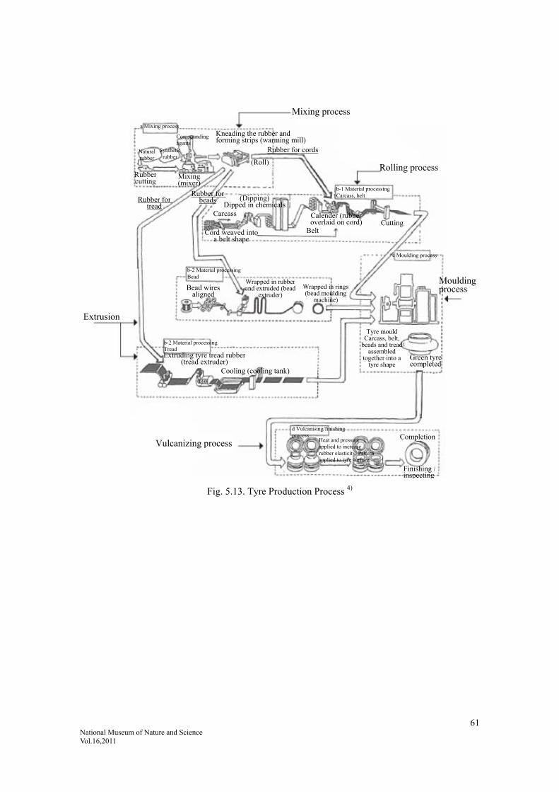
61 National Museum of Nature and Science Vol.16,2011
Fig. 5.13. Tyre Production Process 4)
Mixing process
a Mixing process
Natural rubber
Synthetic rubber
Rubber cutting
Compounding agents
Mixing (mixer)
Kneading the rubber andforming strips (warming mill)
(Roll)
Rubber for cords
Rolling process
b-1 Material processingCarcass, belt
Rubber fortread
Rubber for beads
Carcass
Cord weaved intoa belt shape
(Dipping)Dipped in chemicals
Belt
Calender (rubberoverlaid on cord) Cutting
b-2 Material processingBead
Bead wires aligned
Wrapped in rubberand extruded (bead
extruder) Wrapped in rings(bead moulding
machine)
Extrusion
b-2 Material processing Tread Extruding tyre tread rubber
(tread extruder)
Cooling (cooling tank)
c Moulding process
Mouldingprocess
Tyre mould Carcass, belt,
beads and tread assembled
together into a tyre shape
Green tyre completed
Vulcanizing process
d Vulcanising/finishing process
Heat and pressure applied to increase rubber elasticity. Pattern applied to tyre surface.
Completion
Finishing / inspecting

62 National Museum of Nature and Science Vol.16,2011
Fig. 5.14. Mixer (Banbury Mixer) 5) and Model of the Interior of a Mixer
(3) Details on the Tyre Manufacturing
Process
(i) Mixing (Kneading)
The process of making un-vulcanised rubber by
combining the various compounding agents
weighed according to a recipe. This is a very
important task that affects the properties of the
final product.
Fig. 5.14 shows a Banbury mixer.
These are internal mixers. The material goes
into a central area called a mixing chamber. A
rotor with two blades side by side rotates within
the chamber to create a shearing force between
the opening and the chamber wall. The raw
rubber, carbon black and other fillers placed
into the input are rubbed together and blended.
The blades on the rotor are designed to mix the
materials evenly 5).
(ii) Extruding Process (see Fig. 5.15)
Areas with a predetermined cross-section such
as the tread (the area that comes into contact
with the surface of the road) are achieved by an
extruding process. After being kneaded in the
mixer, the tread rubber is plasticised with a
warming mill and then fed into an extruder,
where it is extruded through a nozzle in a
pre-set tread shape, thereby forming a
predetermined cross-sectional shape. The
extrusion area is then cooled and the tread
rubber is cut to the required lengths and stored.
(iii) Calender Process (see Fig. 5.16)
The calender process produces breakers, belts
and other materials by coating fibres and wire
cords with a thin layer of rubber on both sides
(topping). For steel cord, a creel containing the
necessary number of steel cords to fit the width
of the calender is set in a stand. The wire cords
are unwound from each creel, collected
Weightcylinder
Weight
Input 1
Input 2
Back door Hopper door
Rotor Casing
LatchExhaust Drop door
Rubber is movedand kneaded within the left andright chambers
Rubber is mixed with the compounding agents between the rotor and the casing
Rotorrotates
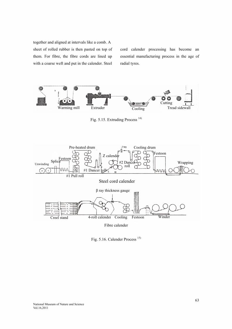
63 National Museum of Nature and Science Vol.16,2011
together and aligned at intervals like a comb. A
sheet of rolled rubber is then pasted on top of
them. For fibre, the fibre cords are lined up
with a coarse weft and put in the calender. Steel
cord calender processing has become an
essential manufacturing process in the age of
radial tyres.
Fig. 5.15. Extruding Process 14)
Fibre calender
Fig. 5.16. Calender Process 15)
Warming mill Extruder Cooling
Cutting Tread sidewall
Unwinding Splice
Festoon
#1 Pull roll
Pre-heated drum
#1 Dancer roll
Z calender
#2 Dancerroll
Cooling drum
Festoon
Wrapping
Steel cord calender
FestoonCoolingCreel stand 4-roll calender
β ray thickness gauge
Winder

64 National Museum of Nature and Science Vol.16,2011
(iv) Moulding Process
This process differs the most between bias and
radial tyres. Fig. 5.17 below shows the
difference in moulding methods between bias
and radial tyres 6).
Fig. 5.17. Tyre Moulding Process 6)
Tyre production involves a number of
components being overlaid, shaped into a tyre,
put into a mould and heated (vulcanised) to
form the final product. While the transition to
radial tyres meant changes had to be made in
all processes, the greatest change was in the
tyre moulding process. The pre-vulcanisation
(pre-heating) state differs for radial and bias
tyres (see Fig. 5.17). From the figure, we see
that the pre-vulcanisation shape of bias tyres is
quite different from the shape of the finished
product after vulcanisation, while the
pre-vulcanisation shape of radial tyres is quite
similar to the shape of the finished product after
vulcanisation.
(v) Vulcanisation Process
This process also differs significantly between
bias and radial tyres, because the shape of the
tyres is quite different prior to vulcanisation.
Tyres that have finished the moulding process
(un-vulcanised tyres) are called green tyres.
These tyres are pressed into a tyre mould by
internal pressure and then vulcanised. At this
point, the tread pattern, side design and
stamped characters on the surface of the mould
are imprinted on the tyre. At the same time, the
tyre is heated inside and out through a medium
such as steam, water or gas and the entire tyre
is undergoes a vulcanisation reaction, turning it
into elastic, vulcanised rubber and the tyre is
completed. Heating is done internally and
externally. There are two methods of external
heating: using a jacket-type hot plate or
shutting the mould in a pressure vessel and
pumping in steam around it. Internal heating is
achieved by inserting an airtight pouch
(vulcanisation bladder or air pack) injected with
steam, water or gas. Since tyres do not have
uniform thickness, heat is not supplied evenly
to all areas, making it difficult to achieve a
uniform degree of vulcanisation. It is important
to complete vulcanisation in such a way to
avoid excessive heating and consequent
deterioration of the rubber. The Bag-O-Matic
Sheet
Fibre reinforcing material
Cylindrical shapeformed by winding the moulding drum
Beads implanted
Ply wrapped
Carcass inflatedonce side tread attached Cap tread and belt attached Tread attached
Green bias tyre
Green radialtyre
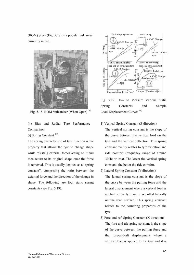
65 National Museum of Nature and Science Vol.16,2011
(BOM) press (Fig. 5.18) is a popular vulcaniser
currently in use.
Fig. 5.18. BOM Vulcaniser (When Open) 20)
(4) Bias and Radial Tyre Performance
Comparison
(i) Spring Constant 18)
The spring characteristic of tyre function is the
property that allows the tyre to change shape
while resisting external forces acting on it and
then return to its original shape once the force
is removed. This is usually denoted as a “spring
constant”, comprising the ratio between the
external force and the direction of the change in
shape. The following are four static spring
constants (see Fig. 5.19).
Fig. 5.19. How to Measure Various Static
Spring Constants and Sample
Load-Displacement Curves 18)
1) Vertical Spring Constant (Z direction)
The vertical spring constant is the slope of
the curve between the vertical load on the
tyre and the vertical deflection. This spring
constant mainly relates to tyre vibration and
ride comfort (frequency range of around
30Hz or less). The lower the vertical spring
constant, the better the ride comfort.
2) Lateral Spring Constant (Y direction)
The lateral spring constant is the slope of
the curve between the pulling force and the
lateral displacement where a vertical load is
applied to the tyre and it is pulled laterally
on the road surface. This spring constant
relates to the cornering properties of the
tyre.
3) Fore-and-Aft Spring Constant (X direction)
The fore-and-aft spring constant is the slope
of the curve between the pulling force and
the fore-and-aft displacement where a
vertical load is applied to the tyre and it is
Loa
d (k
g)
Lat
eral
load
(kg
) T
orsi
onal
torq
ue
(kg-
m)
For
e-an
d-af
t loa
d (k
g)
Vertical spring constant
6.45-13 Bias tyre
165SR13 Radial tyre
Vertical deflection (mm) Lateral deflection (kg)
Torsion angle (˚)
Fore-and-aft deflection (mm)
Lateral spring constant
6.45-13 Bias tyre
165SR13 Radial tyre
165SR13 Radial tyre
165SR13 Radial tyre
6.45-13 Bias tyre
Torque Q, torsion angle α
Torsional spring constant Fore-and-aft spring constant
6.45-13 Bias tyre

66 National Museum of Nature and Science Vol.16,2011
pulled forwards on the road surface. This
spring constant relates to the oscillation of
the tyre in the fore-and-aft direction.
4) Torsional Spring Constant (Z rotation)
The torsional spring constant is the slope of
the curve between the torque and the
torsional angle where a vertical load is
applied to the tyre and the contact area of
the tyre rotates on the road surface with the
centre of the contact area as the centre of
rotation. This spring constant is an indicator
of tyre torsional stiffness. This property is
higher in radial tyres than in bias tyres. The
increased stiffness demonstrates the effect
of the change to radial tyres in the age of
highway travelling.
The radial tyre structure has less rigid sidewalls
and more rigid belts, meaning less flexibility in
the tread area due to the load and a direction of
deflection causing overall eccentricity. Since
the vertical spring constant is measured with
the tyres inflated, radial tyres have a lower
vertical spring constant, but they offer poor ride
comfort over bumps because of the high
rigidity of the belts.
(ii) Rolling Resistance
When comparing the performance of radial and
bias tyres, there is a clear difference in loss due
to deformation because of the degree of
deformation from stress. The difference in the
degree of deformation of the overall tyre is
expressed as a difference in rolling resistance
(related to fuel consumption). Since radial tyres
have a little amount of deformation, they have a
low rolling resistance (good fuel consumption).
As shown in Fig. 5.20, rolling resistance
relative to speed is higher in bias tyres and the
difference increases with speed. As shown in
Fig. 5.21, radial tyres have lower rolling
resistance compared to bias tyres even relative
to load.
Fig. 5.20. Rolling Resistance of Radial and
Bias Tyres 7)
Fig. 5.21. Load and Rolling Resistance 7)
While radial tyres had better fuel consumption,
as shown above, fuel (gasoline) was
inexpensive in the United States at the time,
and the change to radial tyres progressed more
slowly there than in Europe.
Bias tyre: 6.45-13 4PR Radial tyre: 165R13 (steel) Rim: 41/2Jx13 Pneumatic pressure: 1.7kgf/cm2
Load: 385kgf R
olli
ng r
esis
tanc
e (k
gf)
Bias tyre
Radial tyre
Speed (km/h)
Load (kgf)
Rol
ling
res
ista
nce
(kgf
)
Bias tyre:6.45-13 4PR
Radial tyre: 165R13 (steel)
Pneumatic pressure:1.7kgf/cm2

67 National Museum of Nature and Science Vol.16,2011
(iii) Cornering
Two aspects of tyre performance relate to
manoeuvrability: braking and controllability
(cornering). Let us discuss cornering.
Consider a skidding tyre.
When the steering wheel is turned to the right
while the vehicle is in motion, as shown in Fig.
5.22, the operation of the steering wheel puts
the rotational plane of the wheels at an angle to
the direction of travel of the car. Because the
car tries to keep going straight ahead due to
inertia, a disconnection occurs between the
rotational plane of the tyres and the direction of
travel of the car. The angle of this
disconnection is called the slip angle 16).
(a)
Travelling
straight
(b) The
moment the
steering wheel
is turned
α: Slip angle
of the front
wheels
(c) Turning
α: Slip angle
of the front
wheels
β: Slip angle
of the rear
wheels
Fig. 5.22. Relationship Between the Direction
of Travel of the Car and the Direction of
Rotation of the Tyres 16)
(iv) Cornering Force and Self-Aligning Torque
When slipping sideways, the tyres themselves
contort against the surface of the road (see Fig.
5.23). The sideways force exerted on the
vehicle is called the cornering force and causes
the vehicle to move in a curve. The force that
rightens this is called self-aligning torque.
Fig. 5.23. Tyre Slipping Sideways 16)
(v) Difference in Manoeuvrability
When a vehicle is cornering around a bend, a
cornering force is generated to oppose the
centrifugal force on the tyres (see Fig. 5.24).
The cornering force increases in a linear
fashion as the slip angle increases, reaching its
maximum value when the slip angle reaches or
exceeds a certain value. The structural element
with the greatest effect on the cornering force is
the flexural rigidity of the tread area. Radial
tyres have a belt layer with high flexural
rigidity in the tread area, which means that they
offer far greater cornering force than bias tyres.
The slope of the straight-line portion of the
cornering force is called cornering power and is
often used as a property value to indicate
cornering performance. One reason for the
change to radial tyres was their
manoeuvrability. As shown in Fig. 5.25, radial
tyres have greater cornering power than bias
tyres. This means that radial tyres are easier to
drive on and better to manoeuvre.
Wheel surface
Direction of motion
β: Slip angle
Horizontal deflection in the tyre due to force in the horizontal direction
Centre of tyre tread
Traction area
Slip area
Tyre cross-section A, C
Tyre cross-section B

68 National Museum of Nature and Science Vol.16,2011
Fig. 5.24. Cornering Force 17)
Fig. 5.25. Cornering Power and Tyre
Structure8)
As given above, the appearance of steel radial
tyres dramatically improved automobile turning
performance and high-speed straight-line
stability. This is a major factor enabling today’s
safe highway travel for everyone.
The tread area (the area in contact with the
surface of the road) also has the highest
contribution factor to rolling resistance. When
this area is in contact with the surface of the
road, radial tyres fluctuate less and so require
less work. This also means that the area in
contact with the surface of the road fluctuates
less, meaning that radial tyres are also better in
terms of wear resistance.
(vi) Tyre Functions
As mentioned in the introduction, tyres have
the following four functions.
- Bearing a load (support)
- Acting as a spring (absorption)
- Conveying driving and braking forces
(transmission)
- Facilitating steering of the vehicle
(turning)
These are vital functions in which the tyres as
part of the vehicle serve as an intermediary in
establishing a mutual relationship between the
vehicle and the surface of the road. However, it
was not until the transition to radial tyres that
these functions started to be clearly manifested
in tyre development, thanks to easier turning
and transmission with increased rigidity and
other radial tyre characteristics. This also
coincided with the advent of the age of high
speed travel.
5.2.2. Change of Materials
The transition from bias to radial tyres meant a
change in materials as well.
(Polyester, steel cord)
Load
Cornering force CF
Slip angle
Load
Tyres: 165SR13 steel radial165SR13 textile radial6.45-13 4PR bias
Internal pressure: 1.7kg/cm2
Steel radial
Textile radial
BiasCor
neri
ng p
ower

69 National Museum of Nature and Science Vol.16,2011
Rubber/filler/chemicals 80%
Basic Composition
Example of Main Composition Type
Weight Composition Ratio (%)
Rubber
Natural rubber, synthetic rubber
50.5
Reinforcing agent
Carbon black Silica 25.5
Tyre cord Steel cord Textile cord 13.4
Compounding agents
Vulcaniser, vulcanisation accelerator, vulcanisation agent, anti-ageing agent, filler, softener
10.6
Source: Japan Automobile Tire Manufacturers
Association
http://www.jatma.or.jp/index.html
Fig. 5.26. Radial Tyre Composition and
Materials Used in Each Part
(1) Radial Tyre Materials
As previously mentioned, tyres are generally
composed of more than 10 components (see Fig.
1.3 in Chapter 1). Each component has its
respective function; suitable materials are
selected, combined and systematised to fulfil
those functions. Generally, the area that comes
in contact with the surface of the road and the
bead area that comes in contact with the rim are
made of hard rubber, while the sidewall
between these areas is made of soft rubber. The
raw materials consist of rubber and reinforcing
(tyre cord). As shown in Fig. 5.26, the rubber
portion, including rubber, reinforcing agents
such as carbon black, and compounding agents,
accounts for at least 80% of the tyre.
(2) Rubber for Each Component
(i) Tread and Sidewall
Tread rubber (the part that comes in contact
with the surface of the road) plays the role of
transferring the forces applied to the tyre to the
surface of the road. Of all the rubber used in the
tyre, tread rubber has to withstand the most
external mechanical force to protect the tyre
from the road surface so that the
pressure-vessel carcass is not damaged. In
terms of rubber properties, it has to have
superior strength, tearing force and wear
resistance. Accordingly, it is usually a selection
of natural rubber, SBR or BR polymers blended
with fine-grained, high-reinforcing carbon
black. However, while fine-grained carbon
black is highly reinforcing, it generates a lot of
heat when restraining polymer movement. This
is a major issue because it is a fuel-inefficient
behaviour.
Natural rubber has a high balance of
performance; in particular, it is lower in heat
generation than synthetic rubber and is still
often used today in tyres with higher heat
generation during operation, such as truck and
bus tyres, construction machinery tyres and
aircraft tyres.
An increasing amount of SBR was being used
Natural rubber Synthetic rubber Reinforcing material Steel Textile Bead wire Compounding agents

70 National Museum of Nature and Science Vol.16,2011
for passenger vehicle tyres, but the SBR itself
was difficult to process. Use of oil-extended
SBR (oil included during polymer
manufacture) became adopted as standard. This
method was effective for compounds with oil
added to improve processability. Oil-extended
SBR was patented in 1950 by US company
General Tire and was later used throughout the
world.
SBR was the ideal technology for tyre tread for
passenger vehicles, but it took second place to
natural rubber for truck tyres, bus tyres and
other heavy duty vehicle tyres.
Sidewalls do not come into contact with the
ground, but they are subjected to repeated
bending and so must be fatigue resistant. They
are usually made of NR/BR polymer and soft
carbon and are also often combined with
anti-ageing agents because they are exposed to
sunlight. To perform their necessary function,
sidewalls must be flexible, fatigue-resistant,
age-resistant and ozone-resistant.
(ii) Carcass Rubber
Carcass rubber must adhere well to cord, have
low heat build-up and be able to withstand
shear stress. Natural rubber is the main rubber
used because of its superior adhesive properties
and heat generation.
(iii) Belt Rubber
Belt rubber is the rubber that covers the
reinforcing steel cord; natural rubber is mainly
used for this. This rubber must be adhesive to
the steel cord and also age-resistant. This
adhesion and age-resistance are discussed in
more detail in Chapter 6.1.
(iv) Bead Area Rubber
Since the bead area contains a steel wire to
connect the rim and the rubber tyre, the coated
surface of the cord and the rubber must adhere
together. Since this area also has to stay firm,
natural rubber is often used with a lot of carbon
black, with consideration given to heat build-up
and adhesion.
(v) Tubeless Tyre Inner Liner
Solved by using halogenated butyl to maintain
stable tyre pressure (discussed in Chapter 5.1).
(3) Reinforcing Material
The change from bias to radial was not a simple
change in structure; it was also combined with
a change in materials in a very short space of
time. This was particularly evident in
reinforcing material: belts were switched to
steel and carcasses were switched to polyester
(for passenger vehicles). For truck and bus
tyres, both belts and carcasses were eventually
switched to steel.
Passenger vehicle tyres also had a further layer
of fibre reinforcing (cover material) over the
belt. Nylon was often used for this and in some
cases aramid fibre was also used. Fig. 5.27
shows the relationship between tensile strength
and stretch for various fibres.

71 National Museum of Nature and Science Vol.16,2011
Fig. 5.27. Tensile Properties of Various Cords
As shown above, the change from bias to radial
was a significant change, encompassing a
change in structure as well as a change in
materials.
(i) Development of Polyester Cord Carcasses
for Passenger Vehicle Tyres
Polyester is somewhere between nylon and
rayon in nature; it performs better against
various drawbacks of nylon cord, especially in
the areas of flat spots (a temporary flat area on
a tyre against the road having cooled down
after travelling), dimensional stability and
manoeuvrability in smaller tyres such as
passenger vehicle tyres. In other words, in
terms of firmness, it has more rayon-like
properties. Since it is also cheaper than rayon in
price, it could be said in some ways to have
spelled the end of rayon. However, high quality
rayon is still used in top quality tyres where
high manoeuvrability is required.
The drawback with polyester cord is that it has
a greater decrease in strength due to twisting
than nylon or rayon and is less adhesive to
rubber than nylon or rayon. Before RFL
adhesive, now commonly used, it required
two-step processing, needing a primer-like
pre-treatment.
Consequently, it is used in passenger vehicle
tyre carcasses but not on truck and bus tyres
and other tyres with greater shear stress
between the ply. Since the fibre itself is
susceptible to heat build-up, the rubber material
is susceptible to deterioration; furthermore, the
polyester itself can lose strength when the ester
bonds hydrolyse.
(ii) Aramid Cord
Aramid cord was announced as a dream fibre
with twice the strength per weight as nylon and
around eight times the elastic modulus. An
aromatic polyamide in structure, it has the
drawbacks of being expensive, weakening with
repeated compression strain (fibrillisation) and
being difficult to adhere to rubber.
Consequently, it has not been used as a main
reinforcing material.
(iii) Steel Cord
Steel cord wire is high-carbon steel (0.7%)
made into thin strands using a die. This process
hardens it, so it is heat-treated, tempered and
then coated with brass plating to provide a
lubricating effect on the die to make it possible
to draw it. Heat is applied in the vulcanization
process during tyre production; a reaction
between the rubber and the coating during this
Stretch (%)
Steel
Aramid
Vinylon
RayonPolyester
66 nylon
Rubber
Ten
sile
str
engt
h (N
)

72 National Museum of Nature and Science Vol.16,2011
process causes the cord and rubber to adhere
together. In other words, the brass plating not
only acts as an adhesive between the steel cord
and the rubber, but also acts as a lubricant to
prevent friction between the cord and the die
during cord production. The final stage of
drawing is carried out and the strands are
complete. The strands range in thickness from
0.15mm to around 0.38mm. These strands are
twisted together to form the cord. While the
steel cord used varies between tyres, the more
complex the structure, the more is involved in
the twisting process and the greater the cost. In
other words, steel cord with thinner strands and
more twists has better flexural fatigue
resistance, but since this makes the processing
more complicated and increases the price, cord
with a simpler structure is usually used instead.
The plating process, drawing, twisting and
other technologies are essential to development
and much research and development went into
these while radial tyres were being developed.
Japanese steel cord is top-level throughout the
world; it has been highly regarded as having
fewer impurities in the steel wire, meaning
fewer breaks during the drawing process, as
well as other performance factors.
(4) Cord / Rubber Combination
(i) Example Steel Cord Structures
The structures (twist structures) of steel cord
for truck and bus tyres are as shown in Fig.
5.28 (single-layered twist, two-layered twist
and three-layered twist). There are also
structures for larger tyres that have multiple
layers of twists. As seen from these structures,
the single-layered twist structure has 2-5
filaments twisted together; this is often used for
passenger vehicle tyres. The two-layered twist
structure has a 2-3 filament cord in the centre
with 6-9 filaments twisted around it; this is
mainly used in truck and bus tyres. The
three-layered twist structure comprises the
two-layered twist structure with a further 14-15
filaments twisted around it; this is often used
for larger tyres, from truck and bus tyres to
construction machinery tyres
Fig. 5.28. Basic Steel Cord Structures for
Passenger Vehicles, Trucks and Buses 9)
As shown in Fig. 5.29, the structure of steel
cord used in tyres increases in size from that
used in passenger vehicle tyres and that used in
truck and bus tyres. Tyres with heavier loads,
such as truck and bus tyres, have a thicker
structure. Construction vehicle tyres use an
even stronger cord. These steel cords are used
for different purposes according to the size of
the tyre and the site of use.
Single twist
Two-layered twist
Three-layered twist
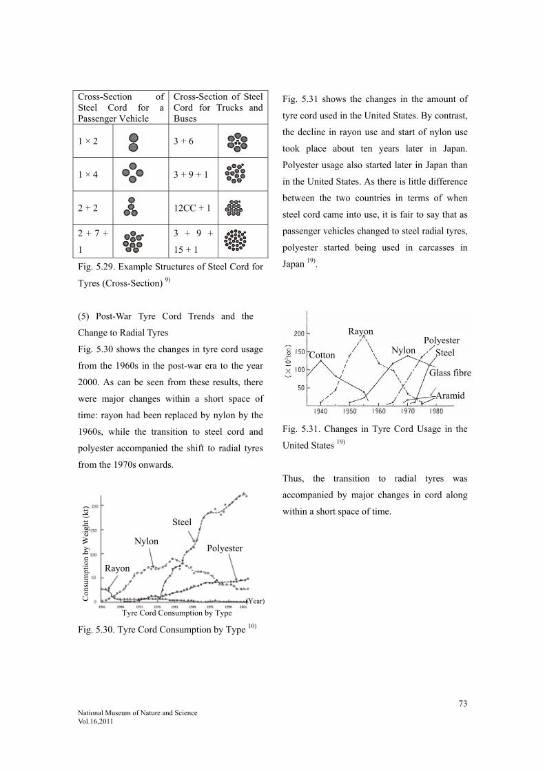
73 National Museum of Nature and Science Vol.16,2011
Cross-Section of Steel Cord for a Passenger Vehicle
Cross-Section of Steel Cord for Trucks and Buses
1 × 2
3 + 6
1 × 4
3 + 9 + 1
2 + 2
12CC + 1
2 + 7 +
1
3 + 9 +
15 + 1
Fig. 5.29. Example Structures of Steel Cord for
Tyres (Cross-Section) 9)
(5) Post-War Tyre Cord Trends and the
Change to Radial Tyres
Fig. 5.30 shows the changes in tyre cord usage
from the 1960s in the post-war era to the year
2000. As can be seen from these results, there
were major changes within a short space of
time: rayon had been replaced by nylon by the
1960s, while the transition to steel cord and
polyester accompanied the shift to radial tyres
from the 1970s onwards.
Fig. 5.31 shows the changes in the amount of
tyre cord used in the United States. By contrast,
the decline in rayon use and start of nylon use
took place about ten years later in Japan.
Polyester usage also started later in Japan than
in the United States. As there is little difference
between the two countries in terms of when
steel cord came into use, it is fair to say that as
passenger vehicles changed to steel radial tyres,
polyester started being used in carcasses in
Japan 19).
Fig. 5.31. Changes in Tyre Cord Usage in the
United States 19)
Thus, the transition to radial tyres was
accompanied by major changes in cord along
within a short space of time.
Fig. 5.30. Tyre Cord Consumption by Type 10)
Rayon
Tyre Cord Consumption by Type
Nylon
Steel
Polyester
(Year) Con
sum
ptio
n by
Wei
ght (
kt)
Aramid
Glass fibre
SteelPolyester
Nylon
Rayon
Cotton
74 National Museum of Nature and Science Vol.16,2011
Cited references:
1) Hattori, Rokurō: Taiya no Hanashi [The Story of the Tyre], Taiseisha, June 1992, p. 6.
2) Watanabe, Tetsuo: Taiya no O-Hanashi [The Story of the Tyre], Japan Standards Association, October 2002, p. 35.
Rewritten to include the latest data from documentation published by the Japan Automobile Tire Manufacturers
Association.
3) Rewritten to combine Watanabe, Tetsuo: Taiya no O-Hanashi [The Story of the Tyre], Japan Standards
Association, October 2002, p. 36, Fig. 1.19 (b) and Hirata, Yasushi: Taiya no Hensen ni tsuite [Changes in Tyres],
Journal of The Society of Rubber Science and Technology, Japan, Vol. 68, 1995, p. 25, Fig. 7.
4) Gomu Gijutsu Nyūmon [Introduction to Rubber Technology], The Society of Rubber Science and Technology,
Japan, ed., Maruzen, October 2005, p. 8.
5) Gomu Kōgyō Binran [Rubber Industry Handbook], fourth edition, The Society of Rubber Science and Technology,
Japan, ed., January 1994, p. 1073.
6) Gomu Kōgyō Binran [Rubber Industry Handbook], fourth edition, The Society of Rubber Science and Technology,
Japan, ed., January 1994, p. 747.
7) Gomu Kōgyō Binran [Rubber Industry Handbook], fourth edition, The Society of Rubber Science and Technology,
Japan, ed., January 1994, p. 750.
Rewritten from Ueno, Kazumi: Jidōsha Gijutsu [Automotive Technology], Vol. 34, No. 10, 1960.
8) Jidōsha-yō Taiya no Kenkyū [Studies on Automobile Tyres], Yokohama Rubber Company, ed., April 1995, p. 138.
Jidōsha Kōgaku Zensho [Compendium of Automotive Engineering], Vol. 12, Tyres and Brakes, Sankaido.
9) Cross-section structures only taken from Gomu Kōgyō Binran [Rubber Industry Handbook], fourth edition, The
Society of Rubber Science and Technology, Japan, ed., January 1994, pp. 557-558, Fig. 2.5 and Table 2.1.
10) Watanabe, Tetsuo: Taiya no O-Hanashi [The Story of the Tyre], Japan Standards Association, October 2002, p.
83. Rewritten by combining this figure with the two figures in Gomu Kōgyō Binran [Rubber Industry Handbook],
fourth edition, The Society of Rubber Science and Technology, Japan, ed., January 1994, p. 549.
11) Drawn up from the Ministry of Land, Infrastructure, Transport and Tourism Road Statistics Yearbook. (See
Buridjisuton Nanajūgo-nen-shi [The 75-Year History of Bridgestone], p. 221.)
12) Sumitomo Gomu Hyakunen-shi [Hundred-year History of Sumitomo Rubber], Sumitomo Rubber Industries, Ltd.,
December 2009, p. 176.
13) Watanabe, Tetsuo: Taiya no O-Hanashi [The Story of the Tyre], Japan Standards Association, October 2002, p.
81.
14) Hattori, Rokurō: Taiya no Hanashi [The Story of the Tyre], Taiseisha, June 1992, p. 126.
15) Hattori, Rokurō: Taiya no Hanashi [The Story of the Tyre], Taiseisha, June 1992, p. 124.
16) Hattori, Rokurō: Taiya no Hanashi [The Story of the Tyre], Taiseisha, June 1992, pp. 58-59.
17) Jidōsha-yō Taiya no Kenkyū [Studies on Automobile Tyres], Yokohama Rubber Company, ed., April 1995, p.
130.
18) Jidōsha-yō Taiya no Kenkyū [Studies on Automobile Tyres], Yokohama Rubber Company, ed., April 1995, pp.

75 National Museum of Nature and Science Vol.16,2011
29-30.
19) Hattori, Rokurō: Taiya no Hanashi [The Story of the Tyre], Taiseisha, June 1992, p. 106.
20) Gomu Kōgyō Binran [Rubber Industry Handbook], fourth edition, The Society of Rubber Science and
Technology, Japan, ed., January 1994, p. 1118.
21) Gomu Kōgyō Binran [Rubber Industry Handbook], fourth edition, The Society of Rubber Science and
Technology, Japan, ed., January 1994, p. 739.

76 National Museum of Nature and Science Vol.16,2011
6. The Coming of Age of Radial Tyres
6.1. The Age of Durability: The Coming of
Age of Radial Tyres in the Age of Durability
Even for radial tyres, the basic area of
performance is durability. Tyres must fulfil
their lifespan. Accordingly, with the transition
to the radial tyre structure, durability was the
first thing that had to be achieved. The early
radial tyre era in particular was a time of
significant durability issues, such as the
adhesion between the steel and the rubber, but
these were overcome as time progressed.
6.1.1. Tyre Breakdown
Two things cause tyres to lose the strength they
had when new: mechanical strain and generated
heat. The extent of this varies according to how
the tyre is used, from uneven terrain and
unpaved roads causing major impact and
deflection to highway-like conditions enabling
high speeds on unobstructed roads with few
bends, stops or starts. Tyres will break down if
they encounter any abnormality that pushes
beyond the limits of their remaining strength.
Care must be taken so that the rubber from
which tyres are composed does not reach that
limit while running. Consequently, it is
necessary to make it harder for the rubber to
lose its strength. This requires a structure that
prevents heat build-up both structurally and
locally.
(1) An Examination of Strain 1)
There are two types of tyre strain: strain
generated by tension from internal pressure
(static) and strain from rolling on the road
surface while supporting a load (dynamic).
(i) Static Strain
Strain generated by tension from internal
pressure differs between radial and bias tyre
structure. In the radial tyre structure commonly
used today, the carcass cord follows a radial
path along the surface of the tyre and has a
fairly uniform level of strain at any given point,
while the strain is reduced slightly in the crown
area due to the hoop effect of the belt. Along
the belt cord, the strain is greatest at the centre
of the crown, while a free end is formed at the
shoulder area with zero strain. By contrast, the
shear strain to counter planar deformation is
greatest at the ends of the cords. Shear strain at
the edges of the radial tyre belt is related to
separation faults (faults in which the rubber
splits and layers peel away) in this area. Belt
edges in truck and bus tyres running with
particularly heavy loads are also a factor for
breakdowns under this same strain (see Figs.
6.1 and 6.2).
Fig. 6.1. Shear Strain on Radial Tyre Belt 1)
(greater at the edges of the belt)
She
ar s
trai
n
Steel belt
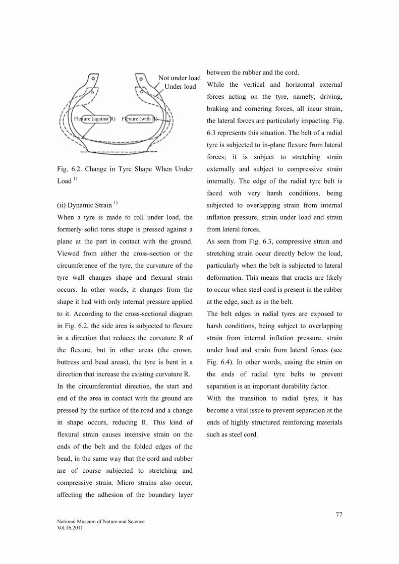
77 National Museum of Nature and Science Vol.16,2011
Fig. 6.2. Change in Tyre Shape When Under
Load 1)
(ii) Dynamic Strain 1)
When a tyre is made to roll under load, the
formerly solid torus shape is pressed against a
plane at the part in contact with the ground.
Viewed from either the cross-section or the
circumference of the tyre, the curvature of the
tyre wall changes shape and flexural strain
occurs. In other words, it changes from the
shape it had with only internal pressure applied
to it. According to the cross-sectional diagram
in Fig. 6.2, the side area is subjected to flexure
in a direction that reduces the curvature R of
the flexure, but in other areas (the crown,
buttress and bead areas), the tyre is bent in a
direction that increase the existing curvature R.
In the circumferential direction, the start and
end of the area in contact with the ground are
pressed by the surface of the road and a change
in shape occurs, reducing R. This kind of
flexural strain causes intensive strain on the
ends of the belt and the folded edges of the
bead, in the same way that the cord and rubber
are of course subjected to stretching and
compressive strain. Micro strains also occur,
affecting the adhesion of the boundary layer
between the rubber and the cord.
While the vertical and horizontal external
forces acting on the tyre, namely, driving,
braking and cornering forces, all incur strain,
the lateral forces are particularly impacting. Fig.
6.3 represents this situation. The belt of a radial
tyre is subjected to in-plane flexure from lateral
forces; it is subject to stretching strain
externally and subject to compressive strain
internally. The edge of the radial tyre belt is
faced with very harsh conditions, being
subjected to overlapping strain from internal
inflation pressure, strain under load and strain
from lateral forces.
As seen from Fig. 6.3, compressive strain and
stretching strain occur directly below the load,
particularly when the belt is subjected to lateral
deformation. This means that cracks are likely
to occur when steel cord is present in the rubber
at the edge, such as in the belt.
The belt edges in radial tyres are exposed to
harsh conditions, being subject to overlapping
strain from internal inflation pressure, strain
under load and strain from lateral forces (see
Fig. 6.4). In other words, easing the strain on
the ends of radial tyre belts to prevent
separation is an important durability factor.
With the transition to radial tyres, it has
become a vital issue to prevent separation at the
ends of highly structured reinforcing materials
such as steel cord.
Not under loadUnder load
Flexure (against R) Flexure (with R)

78 National Museum of Nature and Science Vol.16,2011
Fig. 6.3. Projected Diagram of the Change in
Horizontal Shape of a Radial Tyre Belt and the
Accompanying Stretching and Compressive
Strain on the Belt Edge 1)
Fig. 6.4. Shear Strain on Belt Edge Generated
While Cornering 1)
6.1.2. Durability During the Transition to
Radial Tyres
In terms of the factors that affected tyre
durability in the time of transition to radial
tyres, the major changes were the switch in
structure from bias to radial and the use of steel
cord as a belt material. (Of course, fibre textile
cords were also produced for a while, but steel
radial tyres gradually became the norm.)
The use of steel cord in the belt area of radial
tyres led to a susceptibility to breakdown due to
stress concentration in the boundary layer
between the rubber and the steel cord,
particularly at the edges of the belt, as
mentioned above, due to differences in stiffness
(by four digits on Young’s modulus) between
steel cord and the rubber used in the belt
covering the steel cord (see Table 6.1).
Durability is based on the breakdown
phenomenon; breakdowns often start from
microscopic defects, expanding from that point
and developing into major breakdowns. Belt
edges in particular are free ends and so are
susceptible to cracking (edge separation).
Withstanding breakdown around the steel cord
is required as a basic performance factor.
Table 6.1. Comparison of Various Substances
on Young’s Modulus of Elasticity 17)
Comparison of Various Substances on Young’s
Modulus of Elasticity
Unit N/m2 (Newtons per square metre)
(multiplied by 10-7 to give approximate
kgf/mm2)
Substance Ex1010
Iron 20-22
Copper 13
Aluminium 7
Lead 1.6
Wood (oak) 1.3
Glass 7-8
Polystyrene 0.38
Nylon 66 0.36
Polyethylene 0.076
Elastic rubber (1.5-5.0)x10-4
Durability using steel cord depended on the
durability of the rubber coating to withstand
stress concentration and the adhesion between
Stretching strain from horizontal deformation
Compressive strain from
vertical deformation
Carcass edge line on the stretched side
Carcass centre line (neutral position)
Carcass edge line on the compressed side
Rim centre line
Tyre circumferenceD
epre
ssio
nD
irec
tly
belo
w lo
ad
Kic
king
out
Bel
t wid
th
Air pressure
Load
Lateral force
Stretched side of belt
Compressed side of belt
She
ar s
trai
n on
bel
t edg
e (%
)
Air
infl
atio
n st
rain
Str
ain
unde
r lo
ad
Str
ain
whi
le
corn
erin
g

79 National Museum of Nature and Science Vol.16,2011
the steel cord and the rubber.
Accordingly, let us discuss the durability of the
rubber and the durability of the adhesion
between the steel cord and the rubber.
Generally, rubber loses its strength due to
fatigue deterioration and heat deterioration as it
runs. If it were to come under significant stress
in that state, the rubber layer would break and
the tyre would break down.
(1) Breakdown Due to Ageing of the Rubber
Layer
The rubber covering the steel cord differs from
ordinary rubber in that it has a higher sulphur
content. Where ordinary rubber has a sulphur
content of 1-2 parts per hundred rubber (phr),
this covering rubber has a higher blend of 3-6
parts phr to make it adhere to the steel cord.
This is because higher sulphur blends are better
at adhering to steel cord. However, the higher
the sulphur content, the more quickly the
rubber ages. Also, the higher the heat to which
it is exposed, the quicker the speed of the
ageing. Since the onset of globalisation means
that the same tyres are used throughout the
world, there is a significant increase in the
usage temperature range between hotter
countries and colder countries from what there
used to be. Age and deterioration happen more
quickly in warmer regions. Generally, once the
rubber ages, it becomes hard and its breaking
elongation decreases. If there is a significant
decrease in breaking elongation, the rubber can
no longer handle deformation and the tyre
breaks down. In this sense, how hard the rubber
is during use and how much the stretch has
decreased is an important factor in its durability.
This is particularly important in high-sulphur
blending.
This relationship has been the subject of much
recent research. Fig. 6.5 below shows the state
of ageing rubber.
Fig. 6.5. Changes in Physical Properties
(Modulus; 100% Mod.) During Rubber Ageing
and Correlation to Breaking Elongation λb 2)
The vertical axis in this chart represents the
breaking elongation logarithm (log λb) of
rubber, while the horizontal axis represents the
rigidity modulus (100% Mod) logarithm
(Ahagon plot). Generally, the elongation
decreases linearly with processing time, but if
the processing heat is 80˚C or higher, the line
moves by -0.75 (Type I on the chart). This
indicates that as cross-linking continues,
breaking elongation decreases. Further, as
processing temperature increases, the slope of
the line increases (Type III on the chart). Type
III occurs in the range of 80˚C or over up to
120˚C. While rigidity does not increase in this
range, breaking elongation decreases. This
indicates that elongation decreases more than
Slope = 0.75
Non-running point
Type I
Type II
Type III
(80˚C and less)
(120˚C and more)
(100 ˚C~120 ˚C)

80 National Museum of Nature and Science Vol.16,2011
through the advancement of cross-linking; the
main polymer chains being severed. In other
words, there is a great decrease in break
elongation compared to the amount of Mod
change. When the amount of sulphur in the
rubber increases, ageing becomes faster;
consequently, the straight-line decrease speed
increases. When it drops below a certain
breaking elongation, there is an increased rate
of tyre breakdown. Consequently, with high
sulphur blends it is important to see how slowly
they change; each company has its own special
approaches to blending. Fig. 6.6 shows the
results for actual cars on the market. Here, the
elongation logarithm and Mod logarithm are
over -0.75. Running tyres and spare tyres (not
running) are shown on the same line, showing
that heat has a major impact 3). This method has
made much recent progress as a measurable
method of evaluating rubber durability, both for
material in the laboratory and for rubber from
actual car tyres. Type II is for cases of even
higher temperatures.
LOGMod 100 (Mpa)
Fig. 6.6. Changes in Physical Properties for
Cars on the Market 3)
6.1.3. Decrease in Durability Due to
Deterioration of Adhesion Between the
Steel Cord and the Rubber
Breakdown of tyres due to poor adhesion
between composite layers of different materials
such as fibre and rubber, steel cord and rubber
has become a major issue.
In such cases, the area causing the breakdown
is such a small area volumetrically, such as the
reaction layer in the adhesive interface, that the
phenomenon occurs discontinuously, but it
causes major damage when it does happen. As
the tyre runs, the bonding layer and reaction
layer in the adhesive interface deteriorate and
weaken, resulting in breakdown at some point
in time. This deterioration is intensified by heat,
moisture or a combination of both.
The steel cord and rubber are fastened together
by means of a surface brass plating (copper
(Cu) and zinc (Zn) alloy). When the tyre is
vulcanised (heated), the copper (Cu) in the
plating and the sulphur (S) blended into the
rubber (or other intermediary products
containing sulphur) undergo a chemical
reaction, producing copper sulphide (CuxS
(where x = 1 ~ 2; either copper (I) sulphide or
copper (II) sulphide), zinc sulphide (ZnS), zinc
oxide (ZnO), etc., while the sulphur (S) bonds
with the rubber molecules, forming an adhesion
between the steel and the rubber.
If the plating is thick or has a high proportion
of copper (Cu), the presence of moisture
promotes the production of CuxS, ZnS and
ZnO, hindering adhesion due to a thick layer of
brittle reaction products. If moisture penetrates
during initial assessment (directly after
Running tyres Spare tyres
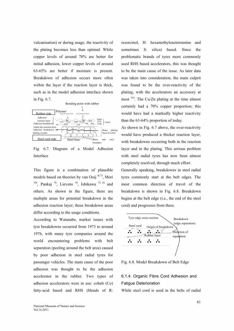
81 National Museum of Nature and Science Vol.16,2011
vulcanisation) or during usage, the reactivity of
the plating becomes less than optimal. While
copper levels of around 70% are better for
initial adhesion, lower copper levels of around
63-65% are better if moisture is present.
Breakdown of adhesion occurs more often
within the layer if the reaction layer is thick,
such as in the model adhesion interface shown
in Fig. 6.7.
Fig. 6.7. Diagram of a Model Adhesion
Interface
This figure is a combination of plausible
models based on theories by van Ooij 4) 7), Mori 10), Pankaj 9), Lievens 8), Ishikawa 5) 6) and
others. As shown in the figure, there are
multiple areas for potential breakdown in the
adhesion reaction layer; these breakdown areas
differ according to the usage conditions.
According to Watanabe, market issues with
tyre breakdowns occurred from 1973 to around
1976, with many tyre companies around the
world encountering problems with belt
separation (peeling around the belt area) caused
by poor adhesion in steel radial tyres for
passenger vehicles. The main cause of the poor
adhesion was thought to be the adhesion
accelerator in the rubber. Two types of
adhesion accelerators were in use: cobalt (Co)
fatty-acid based and RHS (blends of R:
resorcinol, H: hexamethylenetetramine and
sometimes S: silica) based. Since the
problematic brands of tyres more commonly
used RHS based accelerators, this was thought
to be the main cause of the issue. As later data
was taken into consideration, the main culprit
was found to be the over-reactivity of the
plating, with the accelerators an accessory at
most 16). The Cu/Zn plating at the time almost
certainly had a 70% copper proportion; this
would have had a markedly higher reactivity
than the 63-64% proportion of today.
As shown in Fig. 6.7 above, the over-reactivity
would have produced a thicker reaction layer,
with breakdowns occurring both in the reaction
layer and in the plating. This serious problem
with steel radial tyres has now been almost
completely resolved, through much effort.
Generally speaking, breakdowns in steel radial
tyres commonly start at the belt edges. The
most common direction of travel of the
breakdown is shown in Fig. 6.8. Breakdown
begins at the belt edge (i.e., the end of the steel
cord) and progresses from there.
Fig. 6.8. Model Breakdown of Belt Edge
6.1.4. Organic Fibre Cord Adhesion and
Fatigue Deterioration
While steel cord is used in the belts of radial
Bonding point with rubber
Layer
Brass platinglayer (Cu/Zn)
Brass and steelboundary
Steel base
Polymer
Adhesion reaction layer
Adhesion breakdown
within the reaction layer Adhesion breakdown inplating crystals
Steel cord side
Rubber side
Tyre edge cross-section
Steel cord Origin of breakdown
Breakdown (edge separation)
Direction of separation Rubber layer

82 National Museum of Nature and Science Vol.16,2011
passenger vehicle tyres, polyester or rayon are
often used in the carcasses. Recently, nylon has
also often been used as a covering material over
the belt. In heavy vehicles (trucks and buses), it
is common to use steel cord for both the belt
and the carcass.
Carcass Adhesion
Polyester
Since this fibre has poor chemical reactivity on
the surface and does not adequately adhere with
RFL, it is treated with either (1) a two-bath
method in which the surface is treated with
epoxy and then with RFL, or (2) a one-bath
method in which a special adhesive is added to
RFL liquid and blends with the surface of the
polyester (see Fig. 6.9).
Fig. 6.9. Model Adhesion Mechanisms 11)
6.1.5. Deterioration in Place Other than
Around the Belt
Fatigue deterioration also occurs in rubber
outside of the belt area. For each revolution the
tyre makes, the entire area around the
circumference of the tyre comes into contact
with the ground each time, at which point the
entire tread area moves against the ground,
experiences fatigue and is worn away, albeit by
a very tiny amount each time. The carcass is
subjected to bending and deflects, while
fluctuations in the tensile strength of the cord
within the carcass cause repeated shear strain in
the rubber layers between the ply.
Under this behaviour, heat is generated
throughout the tyre, which is subjected to
repeated deformation due to hysteresis loss; this
heat gradually builds up. As a result, the entire
tyre increases in temperature. Temperature
increase has a doubly negative impact on the
lifespan of the tyre.
The first negative impact is that as the
temperature rises, the materials from which the
tyre is composed are subjected to high
temperature, which reduces the lifespan of the
tyre. The second negative impact is that with
continued high temperature, the tyre materials
gradually deteriorate through fatigue. On one
hand, the tyre is gradually losing its tread
rubber; on the other hand, it is losing overall
strength due to high temperature and fatigue.
As mentioned above, usage temperature is
important for durability. The following are
some considerations on usage temperature.
1. Rubber decreases in strength under high
temperatures
2. Rubber ages more quickly under high
temperatures, meaning its strength and breaking
elongation decrease more quickly
Rubber naturally decreases in strength and
deteriorates more when exposed to high
temperature. This means that tyres must have a
greater breadth of heat tolerance now that they
are used throughout the world compared to
when they were only used domestically. In
Rubber Rubber
low molecular RL
Polyester Polyester
Epoxy
Polyester one-bath treatment adhesive
Polyester two-bath treatment adhesive

83 National Museum of Nature and Science Vol.16,2011
other words, the scope of performance for use
in just one country is no longer enough; tyres
need a greater range of durability. In high
temperature regions, there was often trouble
with accelerated deterioration due to heat; it
took time to resolve this.
6.1.6. Accidental Tyre Failure
(1) Cut Burst and Shock Burst
A cut burst is a burst caused by a stone or
similar severing the cord and the tyre no longer
being able to contain the air pressure. A shock
burst is a burst caused by a significant force on
the cord, such as an impact from travelling over
a bump, and the cord layer breaking down
without being severed.
Usually these occur on unpaved roads, but even
on paved roads a tyre can run over an obstacle
such as stone and, enveloping it, deform. If the
obstacle is small, then the tread rubber can
form a localised deformation around it, but if it
is larger, even the carcass could deform around
it. The tyre is affected by the size, shape and
surface friction coefficient of the obstacle,
which alters the degree of stress concentration,
deformation, impact resistance and other
factors applied to the tyre, depending on the
level of air pressure in the tyre, the strength of
the carcass, running speed and other conditions.
This occurs in dump trucks, construction
machinery and other vehicles currently running
on unpaved roads.
6.1.7. Wear Resistance
As the tyre runs, the surface is worn away. The
phenomenon of wear on the tread is extremely
complex, as it varies according to many
different contributing factors. Broadly speaking,
however, it depends on the friction force on the
wheel tread. A tyre travelling at a fixed speed
without any accelerating/decelerating,
cornering or other major friction on the tread
incurs hardly any wear. In other words, the
greater the friction force on the tread and the
road surface, the greater the susceptibility to
wear. The difference in wear life between
vehicles is given as follows 12).
Approximate Wear Life Values 12)
Category Wear Life
Steel
radial
tyres for
passenger
vehicles
General
purpose tyre
30,000-60,000km
High
performance
tyre
20,000-30,000km
Steel
radial
tyres for
trucks
and buses
Transport
truck
200,000-300,000km
Bus 100,000-200,000km
Dump truck 50,000-100,000km
The main causes of significant friction between
tyres and the road surface are (1)
accelerating/decelerating and (2) cornering
(turning).
(1) Subjected to Acceleration/Deceleration
The distribution of contact pressure along the
circumference of the tyre is shown in Figs. 6.10
and 6.11.
These figures indicate that the higher the load,
the higher the contact pressure at both ends. Fig.
6.11 indicates that high contact pressure occurs

84 National Museum of Nature and Science Vol.16,2011
during acceleration/deceleration in the
longitudinal direction (fore-and-aft direction)
when it is pressing in or pressing out. When the
tyre is accelerating/decelerating, the entire tyre
slips. The surface of the tread has traction areas
and smooth areas; these are caused by wear.
In an extreme situation, such as the tyres
locking and being dragged along, or the tyres
are spinning, there are no traction areas. Wear
on the tyre occurs on the smooth areas.
Accordingly, conditions that increase the
smooth areas, such as acceleration or sudden
braking, make the wear on the tyre markedly
prominent.
Fig. 6.10. Characteristics of Contact Pressure in
Passenger Vehicle Tyres 13)
(Horizontal) schematic view (the shoulder area
is lower under lighter loads and higher under
heavier loads)
Fig. 6.11. Characteristics of Contact Pressure in
Passenger Vehicle Tyres 13)
(Horizontal) schematic view (the area directly
after pressing in and directly before pressing
out is lower under lighter loads and higher
under heavier loads)
(2) Subjected to Lateral Forces Due to
Cornering
When a car takes a corner while moving
forward, the tyres slip sideways and lateral
force is produced to counter the centrifugal
force. Away from the contact surface, the
lateral force is of course 0, but within the
contact surface there is a disconnect between
the direction of travel of the tyres and the
surface of revolution due to the slip angle and
the centre lines of these two factors separate.
To begin with, the tread gains traction on the
road surface and there is no relative
displacement between it and the road surface.
As the deformation of the tyre increases and the
rightening force increases, the adhesive force
between the tread and the road surface cannot
be maintained and the tread starts to slip. At the
rear end of the contact area, the carcass centre
and the tread centre line up (see Fig. 6.12). This
action is repeated at every point on the
circumference of the tyre. Wear on the tyre is
generated is the slip areas. The further the
steering wheel is turned, the greater the slip
angle, which increases the lateral force and also
increases the wear on the tyres.
As this wear progresses, the pattern eventually
disappears. It is desirable that the tyre fulfils its
lifespan without the case, which is the skeletal
structure comprising the belt and carcass,
breaking down.
Heavy load 100% load
Light load
Shoulder Shoulder Centre ¼ point ¼ point
Con
tact
pre
ssur
e (k
g/cm
2 )
Heavy load
100% load
Light load
Con
tact
pre
ssur
e (k
g/cm
2 )
Pressing in Directly under load Pressing out

85 National Museum of Nature and Science Vol.16,2011
Since tyres are principally made of rubber, it
should be possible to predict reasonable limits
with an understanding of the stresses applied to
each area. However, the rubber and the fibre
are both high molecular substances and are
subject to thermal and mechanical strength loss
and fatigue deterioration due to increases in
temperature from dynamic deformation as well
as repeated mechanical loading; determining
the allowable stresses is not straightforward.
Technology related to wear has mostly
addressed the wear itself, involving
developments to improve the constitution of
materials, while irregular wear that involves
partial wearing has largely been dealt with by
measures taken in structural design.
Wear-related mechanisms are extremely
complex and quite difficult to assess.
Throughout the long history of tyre technology,
this is one area that remains to be resolved.
While various wear evaluating machines have
been developed for use in laboratories in Japan
and around the world, these are by no means
conclusive.
Radial tyre durability is a major issue. In
particular, the trouble with adhesion between
the steel cord and the rubber has been a major
problem worldwide. Many researchers have
devoted much research into solving this.
6.1.8. Run-Flat Tyres
A New Proposal for Durability
Countermeasures against incidents such as
punctures have always been considered with
driver safety as an underlying issue
Fig. 6.12. Schematic Diagram of Lateral Deformation and Lateral Force Distribution on a Tyre
While Cornering 14)
Direction of rotation of the tyre
Slip angle
Direction of travel of the tyre
Lateral force Adhesive force Slip force
Tread line
Traction area Slip area (Wear occurs in this area)
Carcass line
Contact area
Starting point
(pressing in)
Directly under load
End point(pressing
out)
Above
Lat
eral
disp
lace
men
t(m
m)

86 National Museum of Nature and Science Vol.16,2011
Fig. 6.13. Run-Flat Tyre 15)
Run-flat tyres are tyres that can travel
temporarily even with air pressure at 0 (see Fig.
6.13). This is made possible by means of side
reinforcing rubber fitted into the inner tyre
structure. While this method increases the
weight of each tyre by the amount of
reinforcing rubber used, the overall weight of
the vehicle decreases as it does not require a
spare tyre. There is also a significant benefit to
the user in that not carrying a spare tyre means
more space inside the vehicle.
6.1.9. Summary
As discussed above, the issue of durability is
not unique to Japan alone. Accordingly, the
countermeasures are not uniquely Japanese
technology. Japanese technology in this area
includes: (i) progress on the countermeasures
against the significant problem of steel
adhesion (of course, this happened in other
countries as well); (ii) the proposal of the
predominance of a rubber deterioration
evaluation method (Ahagon plot); and (iii)
progress on run-flat tyres, among others.
Durability is not an issue that changes with the
demands of the times; it must of course be
maintained. It is vital in the environmental age
to prolong the lifespan of tyres; while it is not
at the obvious forefront of performance, it is
growing in importance.
Cited references:
1) Hattori, Rokurō: Taiya no Hanashi [The Story of the Tyre], Taiseisha, June 1992, pp. 92-94.
2) A. Ahagon, Rubber Chemistry and Technology, 59, p. 187, 1986.
3) J. M. Baldwin, D. R. Bauer and P. D. Hurley
Presented at a meeting of the Rubber Division American Chemical Society.
Columbus, OH, 5-8 October 2004.
4) W. J. van Ooij, Rubber Chemistry and Technology, 57, p. 421, 1984.
5) Ishikawa, Yasuhiro: Journal of the Society of Rubber Science and Technology, Japan, 45, p. 921, 1972.
6) Y. Ishikawa, Rubber Chemistry and Technology, 57, p. 855, 1984.
Tyre cross-section
Existing product Run-flat tyre
Shape at 0kPa air pressure
Shape at normal air pressure
Shape at 0kPa air pressure
Side reinforcing rubber

87 National Museum of Nature and Science Vol.16,2011
7) W. J. van Ooij, Kautschuk Gummi Kunststoffe, 44, p. 348, April 1991.
8) H.Lievens, Kautschuk Gummi Kunststoffe, 39, p. 122, February 1986.
9) Patil Pankaj Y. and Ooij W. J, Rubber Chemistry and Technology, 79, p. 82, 2006.
10) Mori, Kunio; Kin, Saisō and Takaomi Yasukawa: Journal of the Society of Rubber Science and Technology,
Japan, 67, p. 293, 1994.
11) Rewritten from Jidōsha-yō Taiya no Kiso to Jissai [Foundation and Reality of Automobile Tyres], Bridgestone
Corporation, ed., Sankaido, January 2006, p. 293.
12) Watanabe, Tetsuo: Taiya no O-Hanashi [The Story of the Tyre], Japan Standards Association, October 2002,
from p. 114.
13) Hattori, Rokurō: Taiya no Hanashi [The Story of the Tyre], Taiseisha, June 1992, p. 87.
14) Hattori, Rokurō: Taiya no Hanashi [The Story of the Tyre], Taiseisha, June 1992, p. 88.
15) “Gomu Erasutomā to Kankyō [Rubber Elastomers and the Environment]”, Rubber Technology Forum, ed.,
Journal of the Society of Rubber Industry, Japan, 2008, p. 104.
16) Watanabe, Tetsuo: Taiya no O-Hanashi [The Story of the Tyre], Japan Standards Association, October 2002, pp.
89-90.
17) Hattori, Rokurō: Taiya no Hanashi [The Story of the Tyre], Taiseisha, June 1992, p. 114.
6.2. The Age of Manoevrability: The
Coming of Age of Radial Tyres in the Age of
Manoeuvrability
6.2.1. Rubber Development for Rolling
Resistance
Since radial tyres are made using steel cord,
which is quite a different material from rubber,
poor adhesion made for significant durability
issues. Many researchers worked to overcome
this issue. The time that followed, from the
1980s onwards, was the age of manoeuvrability.
It was from around this time that distinctly
Japanese tyre products and technology began to
emerge. Looking back at the course of tyre
technology in the post-war era before that, it
was a time of incorporating and learning
overseas technology: overseas technology
adopted after the war, new materials and new
structures, the shift from bias to radial and the
shift from tube to tubeless. In the new era,
Japan made huge contributions by using its
own technology to make fine optimisations.
Many design elements related to durability
were material factors rather than structural
design factors. However, manoeuvrability not
only incorporates material elements such as
rolling resistance (fuel consumption) and
friction (grip), but also structural design
elements for cornering performance, such as
stability and controllability. In other words,
manoeuvrability is an area encompassing both
material factors and structural design factors.

88 National Museum of Nature and Science Vol.16,2011
(1) Contribution of Rubber to Rolling
Resistance
As the rolling resistance of a tyre decreases,
fuel consumption improves. In the
environmental age, there is a demand to reduce
rolling resistance to improve fuel consumption.
The contribution of each part of the tyre to
rolling resistance is as shown in the following
figure. Since tread contributes half of the total,
countermeasures have been focused on tread.
Fig. 6.14. Proportion of Contribution made by
Each Part of a Tyre to Rolling Resistance 1)
(according to the finite element method)
Accordingly, tread rubber has become
important to developments related to rolling
resistance. That is to say, a demand has grown
for low energy loss materials to be used in tread
rubber.
On the other hand, high energy loss is required
for proper braking performance on wet roads
and similar. Consequently, if low energy loss
rubber were to be used in place of existing tyre
rubber, braking performance would decrease.
In other words, there is a trade-off in which the
energy loss has to be as low as possible while
running and as high as possible while braking.
From the perspective of tread rubber, braking
performance is the issue of friction between the
road surface and the tyre tread. Thus, let us
consider rubber friction.
(2) Rubber Friction
The phenomenon of friction between rubber
and a solid surface differs completely from that
of friction between ordinary solid surfaces.
Rubber has a friction coefficient that decreases
as the contact pressure increases; it also relates
to the relative sliding velocity and temperature.
The friction coefficient is greatest when sliding
at a relatively slow velocity rather than in a
state of rest.
Fig. 6.15 shows a model of friction.
Fig. 6.15. Factors in Rubber Friction 3)
When a rubber mass presses against another
solid mass under normal force and slides along
the interface, an adhesive force acts between
the masses through molecular attraction on the
contact surface and resists sliding. If the surface
of the solid mass is uneven, the rubber tries to
fill out the unevenness by compressive
deformation because of its low elasticity.
Consequently, when sliding occurs along the
interface, the areas on the rubber colliding with
Tread 49%
Side 14%
Carcass 11%
Bead 11%
Belt 8%
Other 7%
Friction F Load
Rubber
Hysteresis force FH
Adhesive force FA
Tyre 165R13
89 National Museum of Nature and Science Vol.16,2011
the convex areas on the solid surface are
subjected to compression; when it encounters
the other side of the convex areas or the
concave areas, the rubber is released from that
compression or stretches the opposite way. The
difference in deformation energy coming and
going through localised repetition, that is,
hysteresis loss, acts as friction and is consumed
in the form of heat energy; the corresponding
frictional force acts on the interface.
In other words, total friction = hysteresis force
(FH) + adhesive force (FA). Some friction,
particularly Wet μ (friction coefficient of a wet
road surface), has a very high hysteresis loss
effect. Hysteresis friction is dependent on the
viscoelastic properties of the rubber, such as its
tan δ (hysteresis element; the tangent of the
phase difference δ between vibration stress and
vibration strain) and E’ (modulus of elasticity).
The viscoelastic property is not fundamentally
a breakdown phenomenon, but rather a
response to the strain (deformation) that is
repeatedly applied to the rubber; it depends on
the properties of the overall volume rather than
on the properties of miniscule areas. With
consideration for blending compounds, the
greater the volume of a compounding element
in relation to the whole, the greater the impact
of that element. Usually, in sequence of volume,
the most used material is natural or synthetic
raw rubber (polymer), followed by carbon
black, silica or other reinforcing agents.
Accordingly, in an age where manoeuvrability
is in demand, development is focused on raw
polymers and reinforcing agents.
The greater the friction force, the more difficult
rolling becomes; the higher the resistance to the
rolling of the tyre, the worse the fuel efficiency.
Fuel efficiency and safety are mutually
exclusive phenomena. In other words, as
mentioned above, there is a trade-off between
low rolling resistance (LRR) and friction
(particularly wet friction). Easier rolling means
harder stopping. Currently, it is increasingly
more common to aim for both summer/winter
performance (high grip in high or low
temperature regions in wet or dry conditions)
and LRR wear resistance. Achieving both low
fuel consumption (low rolling resistance) and
high braking performance (grip) has been a
major topic of research addressed by many
researchers since the 1980s.
The time-temperature superposition principle
was used to solve this trade-off. This principle
follows the idea that temperature and time can
be transferred in high molecular substances; the
physical properties at low temperatures
correspond to high-speed (high frequency)
deformation, while the physical properties at
high temperatures correspond to low-speed
(low frequency) deformation. The objective
function uses tan δ, the delay function of the
response to stimulus. Since the rolling
resistance is the resistance acting every time the
tyre rotates, it is the resistance against one
deformation per rotation. This equates to a
frequency of 10Hz (low speed). Meanwhile,
braking (grip) incurs a reciprocating motion in
which deformations are restored against

90 National Museum of Nature and Science Vol.16,2011
protuberances in the surface of the road. In this
case, as the tyre follows minor unevenness in
the road surface, the speed of
deformation/reformation against the
unevenness falls between several tens of
thousands to several million Hz (high speed).
Accordingly, since rolling resistance
corresponds to tan δ of high temperatures and
grip corresponds to tan δ of low temperatures,
they are generally measured as tan δ at 50-60˚C
(rolling resistance) and tan δ at 0˚C (Wet grip),
which quickly developed into a tan δ curve. See
Fig. 6.16.
Fig. 6.16. Temperature and Frequency
Dependency of tan δ and its Relationship to
Required Tyre Properties 2)
From the above, there is a need to reduce tan δ
at 60˚C in order to reduce rolling resistance. To
achieve this requires a low energy loss material.
While using existing low energy loss tyre
rubber such as natural rubber or polybutadiene
(BR) rubber would lower tan δ at 60˚C, it
would also lower tan δ at 0˚C. The peak of the
tan δ curve lies at Tg (glass transition
temperature; the temperature at which the
rubber state starts to congeal into a glassy state).
Consequently, if rubber with a high Tg is used,
tan δ at 0˚C rises, but tan δ at 60˚C also rises.
On the other hand, using a lower Tg, such as
the aforementioned BR, lowers tan δ at 60˚C,
but also lowers tan δ at 0˚C. SBR is often used
to address both factors. While emulsion-SBR
(E-SBR) (emulsion polymerisation; radical
polymerisation) is generally used, another
method is to use solution-SBR (S-SBR)
(solution polymerisation; anionic
polymerisation), which provides an even
steeper tan δ curve at 0˚C and 60˚C (see Fig.
6.17).
Fig. 6.17. Relationship between tan δ and
Temperature for Various Kinds of Synthetic
Rubber 6)
Reducing the amount of carbon is another
known method of steepening the tan δ curve
that is widely used 5).
(3) SBR plays a significant role in passenger
vehicle tyres, such as in the development of
Wet skid resistance
Wet skid resistance Rolling resistance
Frequency
Rolling resistance
Temp. (˚C)
Frequency
Rolling resistance Wet skid resistance
Temperature

91 National Museum of Nature and Science Vol.16,2011
synthesis technology for passenger vehicle
tyre rubber.
It has brought immeasurable diversity to rubber
compounding. This is because SBR can be
freely designed in terms of its microstructure,
modification and other factors. Thus, SBR
makes it possible to have a variety of molecular
designs, ushering in an age of designer
compounds through detailed molecular design
in order to steepen the tan δ curve (1980s, see
Fig. 6.18). The shift from radical
polymerisation (emulsion polymerisation) to
anionic polymerisation (solution
polymerisation) during this time gave a greater
degree of flexibility in molecular design, as
follows.
Fig. 6.18. SBR Microstructure
1. styrene content; 2. vinyl content; 3.
molecular modification
(terminal-modification); 4. molecule weight; 5.
molecular weight distribution; 6. sequence
distribution (styrene sequence distribution)
Since radical polymerisation allows for
variation in styrene content, radical
polymerisation could be used to control rolling
resistance (fuel consumption) by using a low
Tg polymer with a low styrene content;
however, this also reduced tan δ near 0˚C,
meaning a decrease in Wet grip μ. The S-SBR
(solution-polymerisation SBR) method was
introduced as it offered a way to solve this
trade-off using polymer molecular design.
Incorporating molecular design with S-SBR
made it possible to plan the tan δ curve.
Acquisition of S-SBR technology and, by
extension, terminal-modification technology,
made a significant contribution to technology
for reducing rolling resistance.
At this time, methods for steepening the tan δ
curve were worked on together by researchers
around the world. Tyre companies did not have
their own individual theories. Competition
focused on the different effects achieved
through the choice of materials used and the
mixing design.
During this time, Japan devoted much research
to technology for optimising combinations.
Japanese rubber technology made a significant
contribution to this field. The two oil crises in
the 1970s and later environmental issues
resulted in the need for low fuel consumption,
which in turn drove a flurry of research on
modified SBR to improve fuel economy.
(4) Molecular Modification Technology
The catalyst for anionic polymerization is
usually organolithium (alkyllithium;
n-butylithium, etc.). Since these are
living-polymerisable (the ends continue in a
state of live catalytic activity during
polymerisation), if polymerisation is not
interrupted, it will continue its catalytic activity.
Terminal- modification
Styrene (hard portion)
Butadiene (soft portion)
Vinyl (hard portion)
SBR molecular structure

92 National Museum of Nature and Science Vol.16,2011
In binding mode, it is important to control the
styrene content, which serves as a rigid element
for modifying Tg, as well as the vinyl content
(too much will raise the Tg). In anionic
polymerization, the vinyl content can be
controlled either by adding ether compounds,
amine compounds (vinylation agents) or other
compounds during polymerisation or by
controlling the polymerisation temperature.
“Molecular terminal-modified rubber can be
obtained by adding or reacting a modification
agent to the active terminals at the final stage of
anionic or living polymerization using
alkyllithium as a medium, then stopping the
reaction with ordinary methanol or similar.
This binds with the surface of the carbon in the
rubber, mutually binding carbon to carbon,
thereby reducing the friction between carbons,
lowering the tan δ and suppressing heat
generation. N-alkyl benzophenones and N-alkyl
lactams are effective modifiers.” (Technology
by Zeon Corporation et al. 8))
Further, during polymerisation, once 100% of
the monomers have converted to polymers, it is
possible to make use of the fact that the
polymer terminals are active, adding tin, silicon
or other halides or divinylbenzene to cause a
coupling reaction and change the molecular
weight distribution. This technology was
largely researched and developed in Japan 9).
Fig. 6.19 shows a model of coupling and
change in molecular weight distribution due to
tin tetrachloride. (Technology based on Japan
Synthetic Rubber, etc.)
Fig. 6.19. Model of Improved Carbon
Distribution with Sn Modified Polymer 9)
Modified polymer compounding techniques
have become the axis of tread formulation for
both fuel economy and wet grip. This
technology was developed to provide a means
of binding rubber molecules and carbon
together to restrict free movement of the carbon,
as the carbon/carbon friction needs to be
reduced in order to lower the tan δ (reducing
loss and heat generation) of carbon-containing
rubber, as outlined above.
Accordingly, as discussed above, much
research was devoted to technology that would
introduce a functional group with affinity for
carbon at the middle of the polymer and at the
terminals. Noguchi 7), Nagata 8), Ohshima 12),
Tsutsumi 13) and other researchers confirmed
the effect of polymer terminal modification on
lowering rolling resistance. As shown in Fig.
6.19, the idea was to efficiently modify the
polymer terminals and increase the affinity of
the polymer terminals to carbon. In any case,
the idea was to reduce the main viscosity factor
by removing the free terminals. Many patent
applications have also been made in relation to
this 14).
Sn modified polymer C/B
Kneading
Bound rubber

93 National Museum of Nature and Science Vol.16,2011
(5) The Age of Silica
Since 1990, an increasing amount of
technology has switched some of the carbon for
silica, for the purposes of both fuel economy
and wet skid performance. Silica has a
hydrophilic silanol surface, which makes it
difficult to disperse through rubber and prone
to clumping. Consequently, it is more difficult
than carbon to distribute evenly throughout the
rubber. To assist with this, a silane coupling
agent is used to alter the surface of the silica,
which improves its dispersion and also causes a
reaction between the silica and the rubber to
form a bond (primary bond). A lower rolling
resistance is obtained by effectively reducing
the heat generation caused by contact between
silica. This method means the rubber is more
rubbery, which gives tan δ a higher peak; it also
raises tan δ at 0˚C from the perspective of Tg,
which means that silica provides a steeper tan δ
curve than carbon, improving both the rolling
resistance and the wet grip at the same time.
Fig. 6.20 shows a comparison of the
viscoelastic properties of materials made from
carbon compounds and from silica compounds.
Research has also continued on the
viscoelasticity of silica 10). Its use has expanded
throughout the world since the early 1990s,
when Michelin announced its use in green tyres.
It also grew rapidly in popularity due to its
conformity to environmental measures (reduced
CO2 due to lower fuel consumption). Many
researchers have contributed research in
relation to this 15) 16) 17) 18). Much research has
also been carried out around the world on
low-temperature kneading processes, because
the silane coupling agent used has a
cross-linking reagent structure and if it gets too
hot during mixing it will react and become
solidified (burning). To suppress this reaction,
it was found that a mixer with a mesh rotor had
a better cooling effect than existing mixers, so
silica mixers are being switched to this type 10)
11).
Fig. 6.20. Temperature Dependency of tan δ of
Carbon and Silica 4)
5% DSA 10Hz carbon; N234 silica (+TESPT;
coupling agent) base mixture; S-SBR (high
vinyl SBR75/BR25) filler 80 phr oil 32.5
(6) Silica Modification Technology 19)
Technology was also developed to modify
polymers to facilitate the bond with silica, like
the bond between carbon and polymers.
(i) Modification for Silica
Research to introduce a functional group to
SBR that would mutually interact or bond with
silica particles resulted in the development of
typical modified SBRs for blending with silica,
such as diglycidyl amine compounds, cyclic
Carbon
Temperature (˚C)

94 National Museum of Nature and Science Vol.16,2011
imine compounds, halogenated alkoxysilane
compounds at the living terminal or
alkoxy-modified SBR. SBR with terminals
processed by this functional group are
confirmed to have an increased tan δ at 0˚C and
a decrease at 50-60˚C 20).
Fig. 6.21 below shows the effect of modified
polymer rubber on tan δ at 0˚C and at 50˚C.
The effect of both terminal modifier processes
is clearly seen against the unreacted substance 20).
Fig. 6.21. Improved Fuel Economy and Wet
Grip Performance of Various Kinds of
Modified SBR 20)
This figure shows that SBR modified by
reacting with a modifier by anionic
polymerisation has a stronger mutual
interaction with the silica, with better
distribution of the silica particles. At present,
the most effective method is a combination of
switching carbon for silica and modifying the
SBR. Fig. 6.22 shows a model of how these
affect tan δ.
Fig. 6.22. Changes in tan δ Curve (Model) from
Carbon Compounds → Silica Compounds →
Modified Silica Compounds
Many patent applications for modifying
polymers for silica have been filed from Japan 19).
It is fair to say that Japan was demonstrating its
prowess in the technology at the time,
particularly in terminal modification
technology as a means of intricate mixing
design. While the epoch-making technology of
compounding solution-polymerised SBR and
using silica did not originate in Japan, Japan
was very quick in developing, optimising and
implementing it.
6.2.2. Structural Design Elements for
Manoeuvrability
(1) The Effect of Aspect Ratio
As the transition to radial tyres progressed,
tyres with a low aspect ratio became more
popular, particularly for high performance tyres,
in order to improve manoeuvrability. All tyres
came to adopt a lower aspect ratio, even
non-high-performance tyres, as the wider width
and lower height gave them better
manoeuvrability (Fig. 6.23 (A) (B)).
tan δ at 0°C wet skid resistance → improved
5 types of modifiers Processed SBR Unmodified SBR
Direction of improvement
tan δ
at 5
0°C
ro
llin
g re
sist
ance
→ im
prov
ed
Wet skid resistance
Rolling resistance Temperature (˚C)
Base (carbon compound)
(Silica compound) Silica compound + terminal-modified SBR)
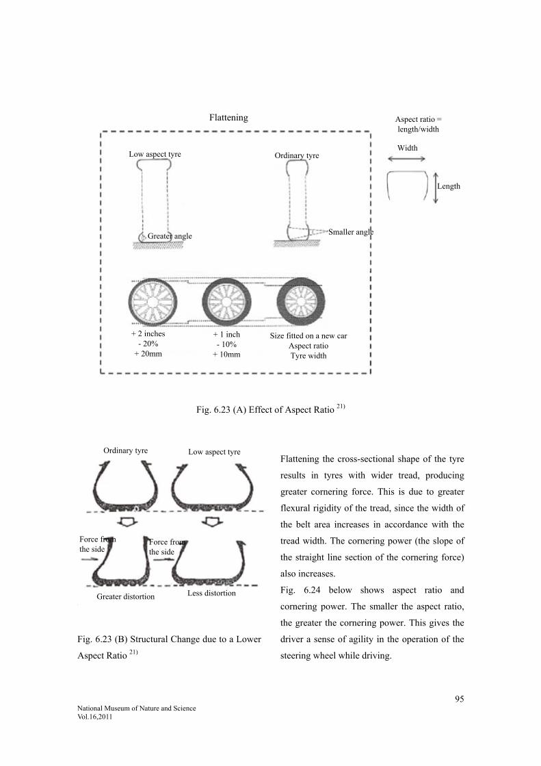
95 National Museum of Nature and Science Vol.16,2011
Fig. 6.23 (A) Effect of Aspect Ratio 21)
Fig. 6.23 (B) Structural Change due to a Lower
Aspect Ratio 21)
Flattening the cross-sectional shape of the tyre
results in tyres with wider tread, producing
greater cornering force. This is due to greater
flexural rigidity of the tread, since the width of
the belt area increases in accordance with the
tread width. The cornering power (the slope of
the straight line section of the cornering force)
also increases.
Fig. 6.24 below shows aspect ratio and
cornering power. The smaller the aspect ratio,
the greater the cornering power. This gives the
driver a sense of agility in the operation of the
steering wheel while driving.
Ordinary tyre
Force from the side
Greater distortion
Low aspect tyre
Less distortion
Force from the side
Flattening
Low aspect tyre Ordinary tyre
Greater angle Smaller angle
+ 2 inches - 20%
+ 20mm
+ 1 inch - 10%
+ 10mm
Size fitted on a new carAspect ratio Tyre width
Aspect ratio = length/width
Width
Length

96 National Museum of Nature and Science Vol.16,2011
Fig. 6.24. Tyre Aspect Ratio and Cornering
Power 22)
Sports cars and other high performance
vehicles are fitted with 50 series, 40 series and
other tyres with a lower aspect ratio, as they
require greater turning power, not only while
turning at high speed, but also while travelling
straight. A lower aspect ratio means a larger
rim diameter for the same outer diameter,
which means larger brake discs and other
fittings can be fitted, which has the advantage
of being good for braking performance. In
review, developments in manoeuvrability
performance are a combination of material
development in the form of controlling
viscoelasticity and structural development in
the form of ratio flattening. In other words, this
aspect of tyre technology development
encompasses both materials and structure.
Japan’s contribution to tyre development
prompted development in the high-performance
tyre category, making advances in tyre
flattening. However, tyre flattening brought
with it a new problem: poor fuel economy.
As discussed in this section, while
developments in manoeuvrability performance
such as silica technology and anionic
polymerization did not originate in Japan,
Japan did absorb the technology and added to it
in areas such as terminal modification, which
made Japanese tyres world class.
In particular, there were major developments in
polymerisation technology among polymer
manufacturers. The material and structural
designs of the time indicate that the level of
technology was rapidly increasing, particularly
among Japanese tyre manufacturers, who were
becoming more well-balanced in all areas of
performance.
Cited references:
1) Gomu Kōgyō Binran [Rubber Industry Handbook], fourth edition, The Society of Rubber Science and Technology,
Japan, ed., January 1994, p. 750.
2) Ozawa,Yoichi: High Polymers,Japan,Vol.54, 2005, p.750.
3) Desmond F. Moore: The Friction of Pneumatic Tyres, Elsevier Scientific Publishing Company, Amsterdam,
Oxford, New York, 1975, p5.
4) Rewritten from Meng-Jiao Wang, “Effect of polymer -Filler and Filler –Filler Interaction on Dynamic Properties
Cor
neri
ng P
ower
Load (kN)
Air pressure: 200kPa
50 series (205/50R16)
60 series (195/60R15)
70 series (185/70R14)82 series (165R14)

97 National Museum of Nature and Science Vol.16,2011
of Filled Vulcanizates”, Rubber Chemistry & Technology, 71, 1998, p. 520, Fig. 47.
5) P.P.A. Smit: Rubber Chemistry & Technology, 41, 1968, p. 1194.
6) “Gomu Kōgyō ni okeru Gijutsu Yosoku — Jidōsha taiya wo Chūshin ni shite [Technology Forecasting in the
Rubber Industry: Focus on Automobile Tyres]”, Rubber Technology Forum, ed., December 1990, Posty
Corporation, p. 110.
7) Noguchi K., Yoshioka A., Komuro K.: Presented at Meeting of Rubber Division, A.C.S. New York (1986)
8) Nagata, Nobuo: Journal of The Society of Rubber Science and Technology, Japan, 62, p. 630, 1989.
9) “Gomu Erasutomā to Kankyō [Rubber Elastomers and the Environment]”, Rubber Technology Forum, ed.,
Journal of the Society of Rubber Industry, Japan, p. 134, cited from Yoichi, Ozawa: Kōbunshi [High Molecular],
54 750 (2005).
10) Matsuda, Takaaki: Journal of The Society of Rubber Science and Technology, Japan, 78, p. 46, 2005, etc.
11) Moribe, Takashi: Journal of The Society of Rubber Science and Technology, Japan, 74, p. 70, 2001.
Moribe, Takashi: Journal of The Society of Rubber Science and Technology, Japan, 81, p. 509, 2008.
Yamada, Norifumi: Journal of The Society of Rubber Science and Technology, Japan, 81, p. 516, 2008, etc.
12) N. Ohshima, F. Tsutsumi, M. Sakakibara: International Rubber Conference 1985, Kyoto.
13) Tsutsumi, Fumio; Sakakibara, Mitsuhiko; Oshima, Noboru; Fujimaki, Tatsuo; Hamada, Tatsuro: Journal of The
Society of Rubber Science and Technology, Japan, 63, p. 243, 1990.
14) Patent application numbers:
Sho-59-196337 (Zeon) Benzophenone terminal treatment; Sho-61-042552 (Zeon) terminal modified SBR;
Sho-61-225228 (Zeon) Terminal tin modification; Sho-63-122740 (Zeon/Yokohama) Amino benzophenone
terminal treatment; Sho-63-66246 (JSR/BS) Tin terminal-modified BR; Sho-63-118343 (JSR/BS) Vinyl aromatic
amine terminal modification; Sho-63-139902 (Sumitomo Chemical) Nitro compound terminal modification;
Sho-63-179949 (JSR/BS) Specific S-SBR tin coupling; Sho-64-040503 (JSR) Terminal tin amine modification;
Sho-64-62341 (JSR) Sn terminal modified BR; Sho-64-69645 (JSR) terminal-modified branched SBR;
Sho-64-118343 (JSR/BS) Nitrogen-containing vinyl compound terminal modification; Sho-64-22940 (JSR/BS)
Amino-group-containing unsaturated compound copolymers or terminal-modified BR or SBR; Hei-01-146937
(Zeon/Yokohama) Amino benzophenone terminal treatment; Hei-01-146939 (Yokohama/Zeon) Amino
benzophenone terminal treatment; Hei-01-158056 (Yokohama/Zeon) Amino benzophenone terminal treatment;
Hei-01-135844 (JSR/BS) terminal modification by high trans tin coupling; Hei-01-35847 (JSR/BS) high trans
butadiene (BR or SBR) function tin coupling terminal modification; Hei-6-279515 (JSR) Reacting tin
compounds, etc. with active polymer terminals; 2000-159813 (Ube) Synthetic diene rubber modified with a
silanol or amine; 2004-276686 (Toyo) Butadiene rubber modified with benzophenone, thiobenzophenone,
isocyanate compounds or halogenated tin compounds; 2005-146115 (Sumitomo) Modification with alkoxysilyls
and/or glycidyl amines; 2007-31722 (Ube) amine-terminal-treated BR; 2007-161798 (Ube) Modification by a
silicon compound having an alkoxy and an amine; 2007-169558 (Sumitomo) Diene rubbers modified by alkoxies
or alkoxy silyls.
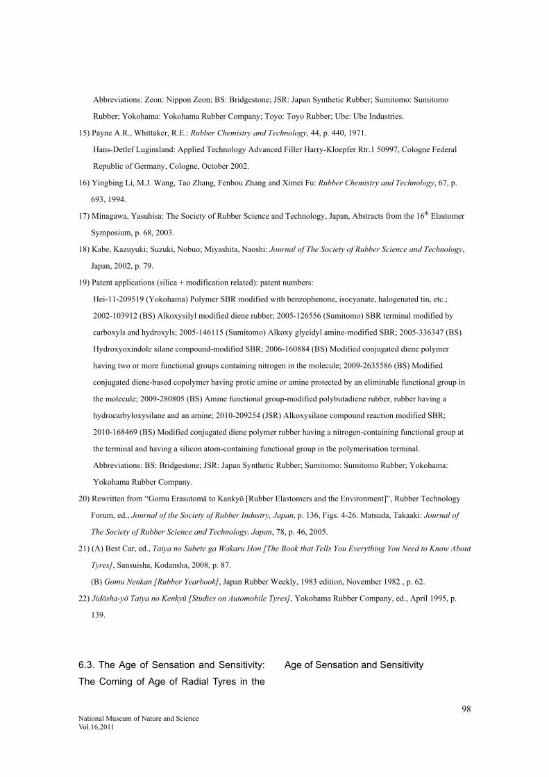
98 National Museum of Nature and Science Vol.16,2011
Abbreviations: Zeon: Nippon Zeon; BS: Bridgestone; JSR: Japan Synthetic Rubber; Sumitomo: Sumitomo
Rubber; Yokohama: Yokohama Rubber Company; Toyo: Toyo Rubber; Ube: Ube Industries.
15) Payne A.R., Whittaker, R.E.: Rubber Chemistry and Technology, 44, p. 440, 1971.
Hans-Detlef Luginsland: Applied Technology Advanced Filler Harry-Kloepfer Rtr.1 50997, Cologne Federal
Republic of Germany, Cologne, October 2002.
16) Yingbing Li, M.J. Wang, Tao Zhang, Fenbou Zhang and Ximei Fu: Rubber Chemistry and Technology, 67, p.
693, 1994.
17) Minagawa, Yasuhisa: The Society of Rubber Science and Technology, Japan, Abstracts from the 16th Elastomer
Symposium, p. 68, 2003.
18) Kabe, Kazuyuki; Suzuki, Nobuo; Miyashita, Naoshi: Journal of The Society of Rubber Science and Technology,
Japan, 2002, p. 79.
19) Patent applications (silica + modification related): patent numbers:
Hei-11-209519 (Yokohama) Polymer SBR modified with benzophenone, isocyanate, halogenated tin, etc.;
2002-103912 (BS) Alkoxysilyl modified diene rubber; 2005-126556 (Sumitomo) SBR terminal modified by
carboxyls and hydroxyls; 2005-146115 (Sumitomo) Alkoxy glycidyl amine-modified SBR; 2005-336347 (BS)
Hydroxyoxindole silane compound-modified SBR; 2006-160884 (BS) Modified conjugated diene polymer
having two or more functional groups containing nitrogen in the molecule; 2009-2635586 (BS) Modified
conjugated diene-based copolymer having protic amine or amine protected by an eliminable functional group in
the molecule; 2009-280805 (BS) Amine functional group-modified polybutadiene rubber, rubber having a
hydrocarbyloxysilane and an amine; 2010-209254 (JSR) Alkoxysilane compound reaction modified SBR;
2010-168469 (BS) Modified conjugated diene polymer rubber having a nitrogen-containing functional group at
the terminal and having a silicon atom-containing functional group in the polymerisation terminal.
Abbreviations: BS: Bridgestone; JSR: Japan Synthetic Rubber; Sumitomo: Sumitomo Rubber; Yokohama:
Yokohama Rubber Company.
20) Rewritten from “Gomu Erasutomā to Kankyō [Rubber Elastomers and the Environment]”, Rubber Technology
Forum, ed., Journal of the Society of Rubber Industry, Japan, p. 136, Figs. 4-26. Matsuda, Takaaki: Journal of
The Society of Rubber Science and Technology, Japan, 78, p. 46, 2005.
21) (A) Best Car, ed., Taiya no Subete ga Wakaru Hon [The Book that Tells You Everything You Need to Know About
Tyres], Sansuisha, Kodansha, 2008, p. 87.
(B) Gomu Nenkan [Rubber Yearbook], Japan Rubber Weekly, 1983 edition, November 1982 , p. 62.
22) Jidōsha-yō Taiya no Kenkyū [Studies on Automobile Tyres], Yokohama Rubber Company, ed., April 1995, p.
139.
6.3. The Age of Sensation and Sensitivity:
The Coming of Age of Radial Tyres in the
Age of Sensation and Sensitivity

99 National Museum of Nature and Science Vol.16,2011
6.3.1. Perception of the Times in the Age
of Sensation and Sensitivity
The course of development of radial tyres
discussed in the preceding sections has seen
some remarkable progress, with a wealth of
research resulting in significant improvements
in durability, rolling resistance (fuel economy)
and aspects of manoeuvrability, such as friction
against the road surface in relation to braking
performance. Durability, rolling resistance and
braking performance are essential to the
operation of the vehicle. There are also various
other non-essential requirements, such as noise,
vibration and ride comfort. While these are not
as essential as durability and aspects of
manoeuvrability performance, such as running,
stopping and turning, as society has matured,
cars have also come of age. Tyres, too, have
become high-performance items with elements
of sensation and sensitivity to them now, in the
sense of eliminating sources of discomfort.
While there always was a demand for these
performance requirements, they grew in
importance once the other more essential
performance factors had been achieved.
In recent years there has been a growing
demand to remove sources of discomfort,
namely noise, vibration and harshness (NVH).
There are two sides to these discomfort factors:
the noise, vibration and ride comfort
experienced by those in the vehicle; and the
discomfort factors (environmental issues)
inflicted on society by the running of the
vehicle, such as noise in the surrounding
environment. Technological development has
advanced on both fronts and the component
technology can be said to have reached a high
level. This relates to the increasing focus on
fuel economy and other environmental issues as
society has advanced.
With the advent of the age of sensation and
sensitivity, recent development has taken the
form of durability + manoeuvrability +
sensation/sensitivity elements. Let us discuss
the technology related to noise, vibration and
ride comfort developed after the war.
(1) Multiplicity in the Age of Sensation and
Sensitivity
The path from durability → manoeuvrability
performance → sensation/sensitivity has been a
road to diversification. A single tyre has to
fulfil various functions at the same time, which
means there are issues that are very difficult to
resolve, since there are a number of trade-offs
that must be both avoided and accommodated
at once. From a tyre design element perspective,
the necessary performances have increased,
from durability → manoeuvrability
performance → sensation/sensitivity.
According to this trend, there has been a shift in
relative importance from material factors to
structural factors. This relationship is shown as
follows.
Target performance:
Durability
→Manoeuvrability
→ Sensation/Sensitivity
(element)
(material)
(material/structural design)
(structural design)

100 National Museum of Nature and Science Vol.16,2011
Since we have entered an age of seeking
relative comfort, the sensation/sensitivity factor
has grown in importance. This has been
reflected in the amount of research from many
angles on tyres as transmitters of vibration.
This is the age of learning how to control the
physical viscoelastic properties of fibre
reinforced rubber (FRR). Various studies have
been carried out from that perspective with the
aim of reducing discomfort.
(2) Vibration / Ride Comfort
While the noise, vibration and ride comfort
experienced by those in the vehicle as well as
the discomfort factors (environmental issues)
inflicted on society by the running of the
vehicle, such as noise in the surrounding
environment, are both factors for consideration,
let us examine harshness and road noise as
sources of noise and vibration experienced by
vehicle passengers.
(i) Harshness
Since radial tyres have a large, rigid belt, they
are less able to encompass protuberances on the
road surface (enveloping power) and are
susceptible to joint shock (running over joins).
In this respect, radial tyres offer poor ride
comfort.
When travelling over uneven areas on road
surfaces, such as joins and bumps, the shock
vibration and noise are called harshness.
Harshness was not such a significant issue
while bias tyres were the norm; it is an issue
that has accompanied the spread of radial tyres.
While it improved somewhat with
improvements to both tyres and vehicles, it has
resurfaced with the popularisation of
low-aspect-ratio radial tyres. The mechanisms
that produce harshness are given as follows.
Unevenness in the road surface causes vibration.
Relatively large irregularities in the road
surface, such as joins or bumps, cause a single
strong jolt to the vehicle, the shock of which
travels through the vehicle’s suspension and
into the car body. The shock noise at this point
has a frequency of 200Hz or less; the problem
with shocks that can be felt in the steering
wheel or seats is the low frequency
back-and-forth vibration at 30-60Hz. This
evaluation is used for riding over protuberances.
Fig. 6.25 shows data on velocity dependence
while travelling over a protuberance. Radial
tyres have a clear peak at 30-50km/h. The
intensity (acoustic pressure) of the noise inside
the vehicle coincides with the longitudinal
acceleration of the floor. This is the cause of
harshness.
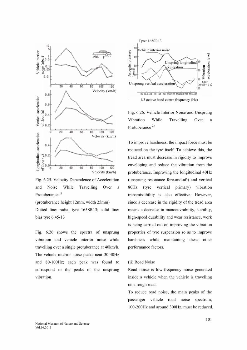
101 National Museum of Nature and Science Vol.16,2011
Fig. 6.25. Velocity Dependence of Acceleration
and Noise While Travelling Over a
Protuberance 1)
(protuberance height 12mm, width 25mm)
Dotted line: radial tyre 165SR13; solid line:
bias tyre 6.45-13
Fig. 6.26 shows the spectra of unsprung
vibration and vehicle interior noise while
travelling over a single protuberance at 40km/h.
The vehicle interior noise peaks near 30-40Hz
and 80-100Hz; each peak was found to
correspond to the peaks of the unsprung
vibration.
Fig. 6.26. Vehicle Interior Noise and Unsprung
Vibration While Travelling Over a
Protuberance 2)
To improve harshness, the impact force must be
reduced on the tyre itself. To achieve this, the
tread area must decrease in rigidity to improve
enveloping and reduce the vibration from the
protuberance. Improving the longitudinal 40Hz
(unsprung resonance fore-and-aft) and vertical
80Hz (tyre vertical primary) vibration
transmissibility is also effective. However,
since a decrease in the rigidity of the tread area
means a decrease in manoeuvrability, stability,
high-speed durability and wear resistance, work
is being carried out on improving the vibration
properties of tyre suspension so as to improve
harshness while maintaining these other
performance factors.
(ii) Road Noise
Road noise is low-frequency noise generated
inside a vehicle when the vehicle is travelling
on a rough road.
To reduce road noise, the main peaks of the
passenger vehicle road noise spectrum,
100-200Hz and around 300Hz, must be reduced.
Velocity (km/h)
Velocity (km/h)
Velocity (km/h)
Veh
icle
inte
rior
no
ise
(μba
r)
Ver
tica
l acc
eler
atio
n of
flo
or (
g)
Lon
gitu
dina
l acc
eler
atio
n of
flo
or (
g)
Aco
usti
c pr
essu
re
leve
l
1/3 octave band centre frequency (Hz)
Tyre: 165SR13
Vib
rati
on
acce
lera
tion
leve
l
Vehicle interior noise
Unsprung vertical acceleration
Unspring longitudinal acceleration

102 National Museum of Nature and Science Vol.16,2011
Various measures have been adopted to achieve
this, including reducing the primary natural
frequency in the radial direction and increasing
the secondary natural frequency of the
cross-section to reduce vibration
transmissibility in the radial direction in the
100-300Hz range, or by reducing the vibration
on the tread due to unevenness in the road by
using softer rubber or thicker rubber.
Fig. 6.27 shows the improvements made by
using these methods. However, although these
methods improved the road noise, there were
other effects, such as reduced manoeuvrability
due to reduced rigidity of the side area, or
poorer fuel economy due to thicker tread
rubber; further countermeasures were needed to
prevent this.
Fig. 6.27. Typical Reductions in Road Noise
from Tyres 3)
(iii) Cavity Resonance
Cavity resonance is resonance from the cavity
within the tyre. In other words, a tyre is like a
pipe that produces a resonant sound. The cavity
resonant frequency equates to a sound wave
frequency with a wavelength the same as the
circumference of a circle with a diameter
approximately halfway between that of the tyre
and that of the wheel. Consequently, the cavity
resonant frequency is determined by the size of
the tyre and does not depend on the tyre
structure. Recent countermeasures have been
considered, such as placing obstacles in the tyre
so that it does not resonate.
(iv) Uniformity Vibration
To improve vehicle vibration and ride comfort
and to reduce noise, it is best if tyres are
completely uniform on their circumference.
Uniformity means uniformity in tyre
dimensions, rigidity and weight. In terms of
tyre uniformity, the change in force during a
single rotation due to non-uniformity on the
tyre axis while the tyre is travelling on a
completely flat road surface is referred to as
force variation. For testing, the following are
measured with a fixed distance between the
tyre and the road wheel (drum) axis.
(1) Radial force variation (RFV): changes in
force in the longitudinal direction
(direction of travel)
(2) Lateral force variation (LFV): changes in
counterforce in the horizontal direction
(3) Tractive force variation (TFV): changes in
force in the fore-and-aft direction; lateral
force deviation (LFD): changes in force
in the fore-and-aft direction (see Fig.
6.28).
Frequency (Hz)
Tyre: 185/60 R14 Vehicle velocity: 60km/h
Before improvements
After improvements
Aco
usti
c pr
essu
re le
vel
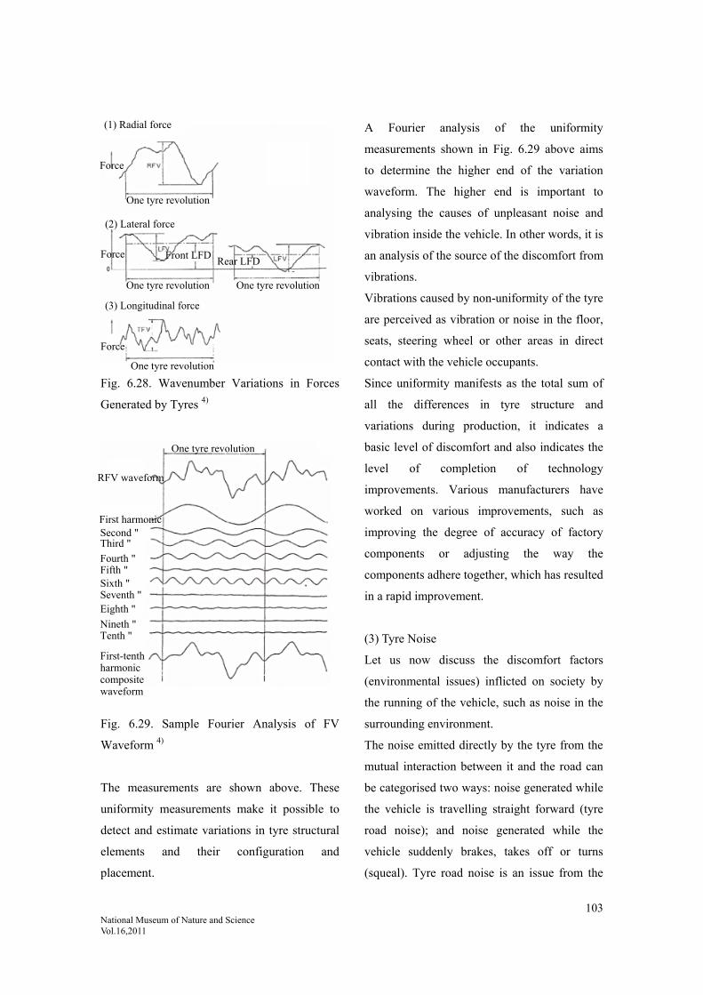
103 National Museum of Nature and Science Vol.16,2011
Fig. 6.28. Wavenumber Variations in Forces
Generated by Tyres 4)
Fig. 6.29. Sample Fourier Analysis of FV
Waveform 4)
The measurements are shown above. These
uniformity measurements make it possible to
detect and estimate variations in tyre structural
elements and their configuration and
placement.
A Fourier analysis of the uniformity
measurements shown in Fig. 6.29 above aims
to determine the higher end of the variation
waveform. The higher end is important to
analysing the causes of unpleasant noise and
vibration inside the vehicle. In other words, it is
an analysis of the source of the discomfort from
vibrations.
Vibrations caused by non-uniformity of the tyre
are perceived as vibration or noise in the floor,
seats, steering wheel or other areas in direct
contact with the vehicle occupants.
Since uniformity manifests as the total sum of
all the differences in tyre structure and
variations during production, it indicates a
basic level of discomfort and also indicates the
level of completion of technology
improvements. Various manufacturers have
worked on various improvements, such as
improving the degree of accuracy of factory
components or adjusting the way the
components adhere together, which has resulted
in a rapid improvement.
(3) Tyre Noise
Let us now discuss the discomfort factors
(environmental issues) inflicted on society by
the running of the vehicle, such as noise in the
surrounding environment.
The noise emitted directly by the tyre from the
mutual interaction between it and the road can
be categorised two ways: noise generated while
the vehicle is travelling straight forward (tyre
road noise); and noise generated while the
vehicle suddenly brakes, takes off or turns
(squeal). Tyre road noise is an issue from the
(1) Radial force
Force
Force
Force
One tyre revolution
One tyre revolution One tyre revolution
One tyre revolution
Front LFDRear LFD
(2) Lateral force
(3) Longitudinal force
One tyre revolution
RFV waveform
First harmonic Second " Third "
Fourth " Fifth " Sixth " Seventh " Eighth "
Nineth " Tenth "
First-tenth harmonic composite waveform

104 National Museum of Nature and Science Vol.16,2011
perspective of noise pollution, in that it is one
of the main contributors to vehicle exterior
noise, which is the subject of legislation. It is
also an issue in that it contributes to the vehicle
interior noise, which compromises the comfort
of the vehicle occupants. Once environmental
issues came to the fore in Japan, manufacturers
have put concentrated efforts into this issue, as
it is a serious issue for the tyre industry.
Japan Automobile Tyre Manufactures
Association (JATMA) and other members of
the Japanese tyre industry carried out months
and years of vital testing and research on how
to reduce noise, from basic studies on tyre road
noise generation mechanisms to investigating
testing methods, ascertaining current road noise
conditions and examining noise reduction
technology and its impact on other performance
factors. JATMA summarised these findings in
Taiya Dōro Sōon ni Tsuite [Tyre Road Noise] 5).
Truck and bus tyres generate more noise than
passenger vehicle tyres. Running trucks and
buses in a small country during a time of
growth, such as Japan’s period of rapid
economic growth, leads to major environmental
issues, particularly in high-traffic areas; the
entire country needed a solution.
In 1973, automobile standard JASO C606-86
“Methods for Testing Automotive Tyre Noise”
was enacted, standardising two methods for
testing tyre road noise: the vehicle coasting test
method, in which tyre road noise was measured
using a vehicle on an actual road, and the
standalone bench test method.
For the vehicle coasting method, the vehicle
was fitted on all four wheels with the tyres to
be tested; it was then put in neutral with the
engine turned off and made to coast at a
predetermined speed past a microphone, which
measured the maximum noise level.
(4) Types of Tyres and Noise
Causes of Tyre Noise
Pattern Noise
The most dominant tyre noise is pattern noise.
This occurs due to a pump effect, in which air
trapped in the grooves of the tread pattern is
released when the tyre rolls and that area either
loses contact with the ground or presses down
against the ground. This is a major source of
noise. Altering the pitch of the pattern disperses
the frequency of the generated pattern noise.
While this does not reduce the sound energy, it
widely disperses the frequency of the generated
noise to make it less noticeable. There is a
relationship between the pitch of the pattern
and the speed of revolution of the tyre. The
noise is generated by a fundamental wave of
around 200-1000Hz and a high frequency wave.
Generally, the greater the number of grooves
(ribs) parallel to the direction of travel, the
quieter the noise; the greater the number of
grooves (lugs/blocks) perpendicular to the
direction of travel, the louder the noise. Bias
tyres are also known to be louder than radial
tyres.
Truck and bus tyre patterns are shown below.

105 National Museum of Nature and Science Vol.16,2011
Fig. 6.30. Typical Truck and Bus Tyre Treads 6)
The following figure shows truck and bus noise
levels. This indicates that lugs>ribs and
bias>radial.
Fig. 6.32 shows passenger vehicle tyre noise.
These results also indicate that lugs and blocks
are louder than ribs, and that bias tyres are
louder than radial tyres.
As indicated in Figs. 6.31 and 6.32, trucks and
buses have more individual tyres and a higher
noise level than passenger vehicles.
Accordingly, since trucks and buses are far
louder than passenger vehicles, reducing their
noise has become a significant issue. For this
reason, many truck and bus tyres today have a
rib pattern. This is a low-noise pattern to reduce
noise pollution in built-up areas. It is one form
of eliminating objectionable environmental
elements.
Fig. 6.31. Noise Levels of Various Truck and
Bus Tyres 7)
(measurements taken at various places offset
with a reference tyre) (vehicle coasting test)
Fig. 6.32. Types of Tyres and Noise (vehicle
coasting test) 8)
(1) Lug (2) Rib (3) Rib-lug (4) Block
Right angle (bias) Bias Bias Bias snow
Ordinary (bias) Radial Radial Radial snow
Radial Straight rib
Speed (km/h)
Radial rib 10.00 R20 14 PR (n=8) Radial lug 10.00 R20 14 PR (n=5) Bias rib 10.00-20 14 PR (n=3) Radial lug 10.00-20 14 PR (n=3)
2-D/4-truck
Noi
se le
vel d
B (
A)
(reference) Radial smooth 165SR13 (n=1)
Speed (km/h)
Noi
se le
vel d
B (
A)
Radial rib 165SR13 (n=4)Radial lug rib 165SR13 (n=5) Radial block 165SR13 (n=2) Bias rib 645-13 (n=6) Bias snow 645-13 (n=6)
1800cc FR sedan

106 National Museum of Nature and Science Vol.16,2011
6.3.2. Summary
As discussed above, in keeping with a growing
demand to make life more comfortable, there
was an increasing demand in post-war tyre
technology development to remove sources of
discomfort in terms of sensation and sensitivity
factors, such as vibration and noise. Much
progress has been made in this area in recent
years as research techniques have improved.
Examination of company patent applications to
ascertain the kind of tyre developments being
undertaken as sensation and sensitivity factors
have grown in importance reveals that
developments in the area of noise and ride
comfort have mainly been design elements such
as tread design and layout. A significant
number of pattern design patents also related to
noise. Most of the patents to do with noise and
vibration given in the cited literature are for
structural design technology 9).
In terms of the relationship between vibration,
noise and frequency, an important task was to
level out the average at a certain frequency to
prevent it being excessively high. This was
developed further with the development of
computers. Research on the discomfort factors
of noise, vibration and harshness has been an
area of technology development that has
completely matched the progress of society. It
is fair to say that it resulted in the coming of
age of tyres.
Cited references:
1) Hattori, Rokuro: Taiya no Hanashi [The Story of the Tyre], Taiseisha, June 1992, p. 76.
2) Jidōsha-yō Taiya no Kenkyū [Studies on Automobile Tyres], Yokohama Rubber Company, ed., Sankaido, April
1995, p. 197.
3) Jidōsha-yō Taiya no Kenkyū [Studies on Automobile Tyres], Yokohama Rubber Company, ed., Sankaido, April
1995, p. 195.
4) Hattori, Rokuro: Taiya no Hanashi [The Story of the Tyre], Taiseisha, June 1992, p. 82.
5) Japan Automobile Tyre Manufacturers Association: Taiya Dōro Sōon ni Tsuite [Tyre Road Noise], fourth edition,
June 1991.
6) Hattori, Rokuro: Taiya no Hanashi [The Story of the Tyre], Taiseisha, June 1992, p. 79.
7) Gomu Kōgyō Binran [Rubber Industry Handbook], fourth edition, January 1994, p. 761.
8) Gomu Kōgyō Binran [Rubber Industry Handbook], fourth edition, January 1994, p. 762.
9) For example, patent applications related to structural design for noise/vibration. Patent numbers:
Hei-05-058119 (BS) side area reinforcing layer arrangement; Hei-06-001109 (Sumitomo) optimum belt layer
configuration; Hei-06-171315 (Yokohama) combination of block and lug grooves; Hei-06-262909 (BS) shoulder
groove siping arrangement; Hei-07-061207 (Sumitomo) inner sidewall indent arrangement; Hei-07-205614 (BS)
block land surface longitudinal groove control; Hei-08-337102 (BS) oriented low-gradient groove arrangement;
Hei-07-276914 (Sumitomo) vibration damping by piezoelectric material; Hei-10-086611 (BS) groove side wall
buffer wall arrangement; Hei-10-147113 (BS) indentation arrangement between side and shoulder; Hei-10-166809

107 National Museum of Nature and Science Vol.16,2011
(Yokohama) maximum width side indentation arrangement; Hei-10-291403 (Toyo) reinforcing layer arrangement
over belt and under ribs; Hei-11-059136 (Toyo) side reinforcing layer arrangement; Hei-11-091314 (BS)
arrangement of inclined grooves at an angle to the central groove; 2000-016030 (Yokohama) side area indentation
arrangement; 2000-158916 (BS) siping groove arrangement; 2000-233609 (Toyo) dynamic vibration absorber
protrusion arrangement; 2001-191743 (BS) carcass side area double-layer arrangement; 2001-239809 (BS)
countermeasures against air column resonance by linking the tread cavity with the circumferential groove;
2002-019423 (BS) block arrangement design; 2003-011617 (BS) asymmetric centre block arrangement on the
press-out and press-in sides; 2003-260906 (BS) width-direction intervals in the belt layer with specific widths;
2004-351970 (BS) pitch arrangement; 2005-145429 (Sumitomo) cushion rubber arrangement between the belt and
carcass; 2006-199101 (Toyo) extending the block from the shoulder to the side; 2008-024256 (Yokohama) carcass
bead area reinforcing layer arrangement; 2009-107448 (Yokohama) double-layer shoulder carcass arrangement
Abbreviation: BS: Bridgestone; Sumitomo: Sumitomo Rubber; Yokohama: Yokohama Rubber Company; Toyo:
Toyo Rubber
6.4. The Age of Integration: the Coming of
Age of Radial Tyres in the Age of
Integration
6.4.1. Advent of the Age of Theory
(Theorisation for the simultaneous achievement
of performance factors such as durability and
manoeuvrability; fuel economy, grip and
sensitivity; noise, vibration and ride comfort)
Underlying the shifting trend from durability →
manoeuvrability performance →
sensation/sensitivity has been a shift on
emphasis from material elements to structural
elements. Nevertheless, techniques to achieve
these target outcomes have been narrow in
scope, with durability limited to material
factors and sense/sensitivity limited to
structural design factors.
From the 1980s onwards, Japanese
manufacturers starting publishing a succession
of theories on tyre design. By establishing
mutual connections between different areas,
such as incorporating design elements into
durability and rolling resistance, which had
previously been considered as mainly involving
material design issues, these studies enabled
new developments, which provided
breakthroughs for existing trade-offs. These
theories were mainly to do with the geometric
design of tyres with presuppositions closer
actual running conditions, namely, filled with
air and under load. In other words, the ideas
that surfaced took into account the tension
distribution during use, the changing shape of
the tyre and other factors. In short, these
theories proposed major strides in progress by
using structural design elements to solve
performance issues that had previously been
viewed as falling into the material elements
category. Furthermore, these were also being

108 National Museum of Nature and Science Vol.16,2011
published by all companies.
Structural designers expanded their scope of
investigation from their main areas of
responsibility, namely, noise, vibration, ride
comfort, driving stability, etc. to include
durability and rolling resistance through carcass
tension control.
This theorisation coincided with the
development of computers. The age of
super-computers ushered in a drastic leap in
complexity, combining all kinds of factors:
examining what kind of materials to use and
how to structure them, whether or not fibre
reinforced rubber could work, and determining
physical constants such as frequency and
acoustic pressure for vibration, sound and other
factors, particularly in the area of sensation and
sensitivity. As these factors grew in importance,
more advanced calculations were required,
paving the way for large-scale computers and
the finite element method.
With the advance of globalisation, tyres had to
become more diverse to meet a broadening
range of usage conditions. The technology also
had to diversify, which required a
multidisciplinary approach. This necessitated
an integration of materials and design, given
the mutual relationship between material design
elements and structural design elements. This
was an age of tyre design theory, encompassing
durability and manoeuvrability performance
factors as well as all aspects of sensation and
sensitivity factors. The task of finding and
balancing a compromise between factors
without sacrificing any of them was a task well
suited to the Japanese. Combined with
advanced computer design technology, this
worked to the advantage the overall situation.
Consequently, the level of Japanese integration
technology during this era was world class. The
following are some of the theories by various
companies.

109 National Museum of Nature and Science Vol.16,2011
Rolling Contour Optimisation Theory (RCOT), Buridjisuton Nanajūgo-nen-shi [The 75-Year History of
Bridgestone], p. 232
At the time, manufacturers around the world were designing tyres based on natural equilibrium shape theory. This
shape is determined mathematically under conditions in which the tension of the air pressure is applied uniformly and
is thought to be the most stable shape for a tyre.
A FEM model was created in which minute differences in tyre shape were deliberately emphasised and the energy
loss predicted. The theory held that deformation could be absorbed by increasing tension to suppress deformation in
areas susceptible to energy loss and reducing tension in areas not prone to energy loss. This is the main idea behind
the RCOT theory, to “distribute the necessary tension to the necessary areas.” Specifically, the theory proposed a
non-equilibrium cross-section shape to increase the tension at the bead and belt areas (optimal travelling shape
theory).
RCOT Carcass Shape and Tension Distribution
Jidōsha-yō Taiya no Kiso to Jissai [Foundation and Reality of Automobile Tyres], Bridgestone Corporation,
Sankaido, p. 94.
Tension Control Optimisation Theory (TCOT), Buridjisuton Nanajūgo-nen-shi [The 75-Year History of
Bridgestone], p. 233; Watanabe, Tetsuo: Taiya no O-Hanashi [The Story of the Tyre], (Japan Standards Association),
p. 123.
Clarifying the tyre distortions and their occurrence mechanisms and attaining a shape to suppress those distortions by
TBR new shape design theory.
Since TCOT increases the radius of curvature of the carcass at the bead area and reduces the radius of curvature at
the top of the sides, tension increases at the bead area, which reduces deformation, thereby improving the durability
of the bead area. This increase in tension and reduction in deformation of the bead area improves durability by 20%
and at the same time also improves rolling resistance, wear resistance, wet braking performance, driving stability and
other trade-off performance factors.
Fig. 6.33. Buridjisuton Nanajūgo-nen-shi [The 75-Year History of Bridgestone], (Bridgestone Corporation, May
2008) 1) pp. 232-233
RCOT shape
Conventional shape
Belt tension distribution (circumferential direction)
RCOT shape tension distribution
RCOT shape tension distribution
Conventional shape tension distribution
Conventional shape tension distribution
Car
cass
tens
ion
dist
ribu
tion
(r
adia
l dir
ecti
on)

110 National Museum of Nature and Science Vol.16,2011
Driver Oriented New Ultimate Tyre Science (DONUTS), Buridjisuton Nanajūgo-nen-shi [The
75-Year History of Bridgestone], p. 305.
DONUTS is a technology comprising three other technologies: Grand Unified Tyre Technology
(GUTT), an automated evolutionary design method; O-Bead, a bead with improved roundness; and
Long Linkage (LL) carbon.
GUTT is a method of optimising target performance factors through computer simulation.
O-Bead is a shape of bead that fits the rim and tyre in a near-perfect circle, improving the straight
running stability of the tyre. LL carbon is a new type of carbon that has an increased chain of carbon
particles to achieve both improved wear resistance and reduced rolling resistance, previously
thought to be mutually exclusive.
Advanced Quality of DONUTS (AQ DONUTS), ibid, p. 326.
Adoption of two technologies to prevent deterioration of performance due to on-going wear on the
tyre, particularly when wet.
- AQ compound: use of compounding agents to suppress the hardening of the rubber
- Tread in tread: Once the tyre is worn to around half, rubber appears to suppress the gradual decline
in performance, preventing the deterioration in wet performance and other performance factors.
Maximised Belt and Bead Tension Distribution using GUTT
Jidōsha-yō Taiya no Kiso to Jissai [Foundation and Reality of Automobile Tyres], Bridgestone
Corporation, Sankaido, p. 96.
Fig. 6.34. Buridjisuton Nanajūgo-nen-shi [The 75-Year History of Bridgestone], (Bridgestone
Corporation, May 2008) 2) pp. 305, 326.
Conventional shape belt tension GUTT shape belt tension
Conventional shape carcass tension
Conventional shape
GUTT shape
GUTT shape carcass tension

111 National Museum of Nature and Science Vol.16,2011
PSP-Y, (Sumitomo Gomu Hyakunen-shi [Hundred-year History of Sumitomo Rubber]), p. 376; 1996, fitted tyre sale,
p. 376.
A new technology developed to address a change in required performance for truck and bus tyres from the
conventional “strength to withstand heavy loads” to “mobility”, “maintenance” and “economy”.
- Adoption of particulate carbon to improve tyre life and travelling performance by strengthening the bond between
the rubber and the carbon
- Flat, smooth, tread shape design to improve uneven wear resistance by suppressing dimensional changes in tyres
from travelling
- Tread block layout design based on independent chaos theory to reduce noise by dispersing the noise generated by
the tyre grooves, as well as to improve uneven wear resistance
- New bead structure design to improve rim insertion when fitting the tyre to the wheel and to improve air insertion
when inflating the tyre
Evolution into Dunlop Energy Control Technologies (DECTES), p. 440.
Adjusting the distribution of ground contact area to evenly distribute wear energy and prevent uneven wear resulted
in less maintenance; adopting highly active carbon in the tread rubber resulted in improved tyre life; suppressing the
energy loss incurred with each revolution of the tyre resulted in lower fuel consumption.
Digital Rolling Simulation (DRS) → Digi-Tyre, ibid, p. 382.
Analysis of a rolling tyre model, reproduced exactly from the tread pattern to the detailed tyre structure.
Four type of simulations
(i) Contact shape / contact pressure simulation: “digital profile” allowing viewing of the contact surface of a tyre
while travelling at 200/h
Led to the implementation of greater driving stability at high speeds with a wide ground contact surface at high
speed.
(ii) Wear energy simulation: “digi-tyre pattern” allowing viewing of where the tyre is wearing away
Block shape enabled even wear energy across the ground contact surface of the tyre while rolling, reducing uneven
wear and lengthening the life of the tyre.
(iii) Rubber compound simulation: “digi-tyre silica water-repellent rubber” enables the digi-tyre to run on any road
surface
Proper blending of water-repellent rubber for summer, silica for wet use and particulate carbon for dry use,
improving both wet grip and tyre life.
(iv) Noise / vibration simulation: “digi-tyre chaos array” allows hearing of tyre sounds while running
An array formed with an appropriate mix of regularity and irregularity, resulting in a balance between preventing
uneven wear, which requires regularity, and reducing noise, which requires irregularity.
Fig. 6.35. Sumitomo Gomu Hyakunen-shi [Hundred-year History of Sumitomo Rubber] (Sumitomo Rubber Industries,
Ltd., December 2009) 3), p. 440, 382
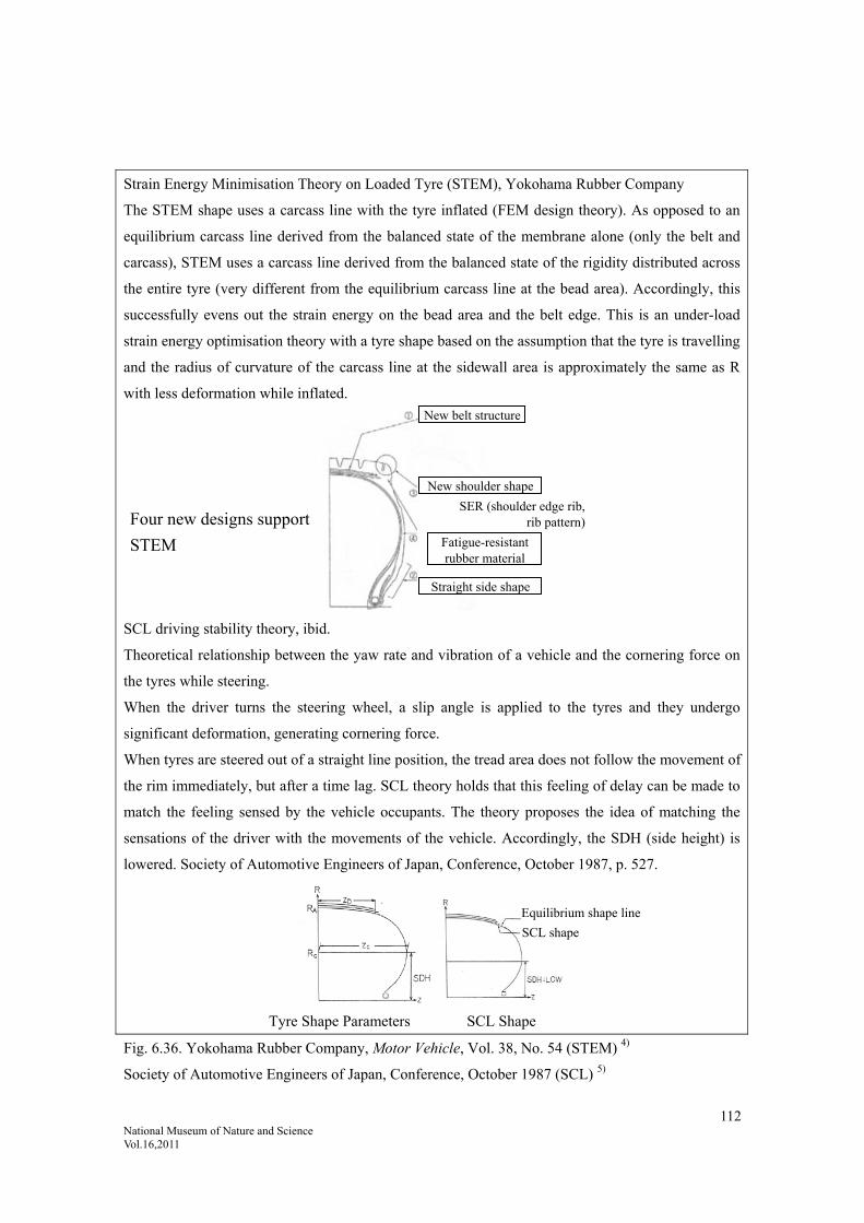
112 National Museum of Nature and Science Vol.16,2011
Strain Energy Minimisation Theory on Loaded Tyre (STEM), Yokohama Rubber Company
The STEM shape uses a carcass line with the tyre inflated (FEM design theory). As opposed to an
equilibrium carcass line derived from the balanced state of the membrane alone (only the belt and
carcass), STEM uses a carcass line derived from the balanced state of the rigidity distributed across
the entire tyre (very different from the equilibrium carcass line at the bead area). Accordingly, this
successfully evens out the strain energy on the bead area and the belt edge. This is an under-load
strain energy optimisation theory with a tyre shape based on the assumption that the tyre is travelling
and the radius of curvature of the carcass line at the sidewall area is approximately the same as R
with less deformation while inflated.
SCL driving stability theory, ibid.
Theoretical relationship between the yaw rate and vibration of a vehicle and the cornering force on
the tyres while steering.
When the driver turns the steering wheel, a slip angle is applied to the tyres and they undergo
significant deformation, generating cornering force.
When tyres are steered out of a straight line position, the tread area does not follow the movement of
the rim immediately, but after a time lag. SCL theory holds that this feeling of delay can be made to
match the feeling sensed by the vehicle occupants. The theory proposes the idea of matching the
sensations of the driver with the movements of the vehicle. Accordingly, the SDH (side height) is
lowered. Society of Automotive Engineers of Japan, Conference, October 1987, p. 527.
Tyre Shape Parameters SCL Shape
Fig. 6.36. Yokohama Rubber Company, Motor Vehicle, Vol. 38, No. 54 (STEM) 4)
Society of Automotive Engineers of Japan, Conference, October 1987 (SCL) 5)
New belt structure
New shoulder shape
Fatigue-resistant rubber material
Straight side shape
SER (shoulder edge rib,rib pattern)Four new designs support
STEM
Equilibrium shape line
SCL shape
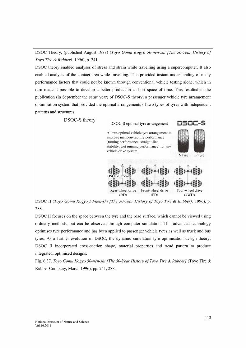
113 National Museum of Nature and Science Vol.16,2011
DSOC Theory, (published August 1988) (Tōyō Gomu Kōgyō 50-nen-shi [The 50-Year History of
Toyo Tire & Rubber], 1996), p. 241.
DSOC theory enabled analyses of stress and strain while travelling using a supercomputer. It also
enabled analysis of the contact area while travelling. This provided instant understanding of many
performance factors that could not be known through conventional vehicle testing alone, which in
turn made it possible to develop a better product in a short space of time. This resulted in the
publication (in September the same year) of DSOC-S theory, a passenger vehicle tyre arrangement
optimisation system that provided the optimal arrangements of two types of tyres with independent
patterns and structures.
DSOC II (Tōyō Gomu Kōgyō 50-nen-shi [The 50-Year History of Toyo Tire & Rubber], 1996), p.
288.
DSOC II focuses on the space between the tyre and the road surface, which cannot be viewed using
ordinary methods, but can be observed through computer simulation. This advanced technology
optimises tyre performance and has been applied to passenger vehicle tyres as well as truck and bus
tyres. As a further evolution of DSOC, the dynamic simulation tyre optimisation design theory,
DSOC II incorporated cross-section shape, material properties and tread pattern to produce
integrated, optimised designs.
Fig. 6.37. Tōyō Gomu Kōgyō 50-nen-shi [The 50-Year History of Toyo Tire & Rubber] (Toyo Tire &
Rubber Company, March 1996), pp. 241, 288.
N tyre P tyre
DSOC-S optimal tyre arrangement
Allows optimal vehicle tyre arrangement to improve manoeuvrability performance (turning performance, straight-line stability, wet running performance) for any vehicle drive system.
DSOC-S theory
Rear-wheel drive (RD)
Front-wheel drive (FD)
Four-wheel drive (4WD)
DSOC-S theory

114 National Museum of Nature and Science Vol.16,2011
Cited references:
1) Burdijisuton Nanajūgo-nen-shi [The 75-Year History of Bridgestone], Bridgestone Corporation, May 2008, p. 232.
2) Buridjisuton Nanajūgo-nen-shi [The 75-Year History of Bridgestone], Bridgestone Corporation, May 2008, pp.
305, 326.
3) Sumitomo Gomu Hyakunen-shi [Hundred-year History of Sumitomo Rubber], Sumitomo Rubber Industries, Ltd.,
December 2009, pp. 440, 382.
4) Yokohama Rubber Company, Motor Vehicle, Vol. 38, No. 54.
5) Hanada,Ryoji: Society of Automotive Engineers of Japan, Conference, October 1987, summary, p. 527.
6) Tōyō Gomu Kōgyō 50-nen-shi [The 50-Year History of Toyo Tire & Rubber], Toyo Tire & Rubber Company,
March 1996.

115 National Museum of Nature and Science Vol.16,2011
7. Detailed Description of Tyres Requiring Additional Performance
The preceding chapters have systematically
discussed the ordinary properties of tyres. In
other words, we have outlined the history and
systematisation of technology related to
performance factors that are ordinarily required
in tyres, such as durability, manoeuvrability,
noise and vibration. However, some tyres
require additional, extreme performance factors.
This chapter discusses the history of
development of tyres requiring special
performance factors, including aircraft tyres,
construction vehicle tyres (high durability),
two-wheeled vehicle tyres (structure) and
studless tyres (snow and ice friction).
These tyres have presented challenges to meet
the required performance factors.
7.1. High Demand for Durability
7.1.1. Aircraft Tyres: High Thermal
Fatigue Resistance
Aircraft tyres are only required for take-off and
landing.
Aircraft tyres must be able to soften the impact
when the aircraft touches down on the runway
and perform sufficiently to bring the aircraft to
a safe stop. Accordingly, the tyres must have a
structure capable of bearing sufficient load
capacity, handling the speeds required for
aircraft take-off and landing and adequately
withstanding the wear from the surface of the
runway. Aircraft tyres have a fixed number of
uses, depending on the aircraft performance
(weight, take-off and landing speeds), runway
conditions, weather conditions and manner of
braking. The tread pattern is usually a rib type,
comprising four to six grooves running in the
circumferential direction. After 200-300
take-offs and landings, the grooves wear away
and the tyre is replaced. In many cases, the tyre
is retreaded, with the worn tread removed and
new tread put on. The retreading process can be
repeated five to six times.
During landing, the tyres are subjected to
significant vertical impact at the moment of
contact with the ground. Since they go from not
moving during flight to suddenly rotating, the
tyres are subjected to major acceleration in the
tangential direction against the runway surface
on contact with the ground and are rubbed
vigorously. Compared to ordinary tyres, aircraft
tyres have the following distinguishing
characteristics 9).
(i) Aircraft tyres have significant flexure. While
the flexure under static load varies between
tyre types, it is around 30% (within the
range of 23.5-40%), two to three times more
than automobile tyres. This helps to ease the
shock during take-off and landing,
particularly during landing.
(ii) Very high loading. Since the tyre size and
weight are reduced as much as possible to
lighten the weight of the fuselage as much as
possible, the tyres carry a very high load in
proportion to their size.
(iii)Superior high-speed performance. Since
aircraft reach speeds of up to around

116 National Museum of Nature and Science Vol.16,2011
400km/h during take-off and landing, tyres
must be stable and safe at high speeds.
(iv) Good cold tolerance. Tyres must be made
of a material that can stand temperatures of
-40 to -50˚C, since they are used at airports
in cold regions and are stowed during flights
through the stratosphere. Furthermore, when
landing, the tyres are required to spin,
despite having hardened due to the low
temperatures.
Type of aircraft tyres include small and
medium tyres, or low-pressure propeller aircraft
tyres, high-pressure jet aircraft tyres,
newly-designed flattened tyres and helicopter
tyres, among others. There are also many
different sizes of tyres, ranging from 56”
(around 1.4m) tyres for large aircraft to 12”
(around 30cm) tyres for small aircraft tyres.
While both bias and radial structures exist for
aircraft tyres as well, the radial structure is on
the way to becoming adopted as the main
structure in use. However, on the whole, bias
tyres are still the main structure in use, with
more than 20 layers of nylon cord to ensure
safety. Given the low temperature performance
factor, natural rubber is used as the rubber
material. This is because once a fuselage is
developed, it is fitted with the same structure of
tyres for 20-30 years until it is retired from
service; there are no rapid changes made. In
future, there will be a change to radial tyres, as
radial tyres are becoming known for their high
durability, light weight and good landing
performance.
The high durability requirement for aircraft
tyres means that they must have high rupture
tolerance and low heat build-up. Accordingly,
natural rubber is used for aircraft tyres. Aircraft
tyres have a long history as far as tyres go,
dating back to pre-war fighter aircraft, and the
technology has been built up from that
foundation. The strongest requirement is for
safety; changes in specifications cannot be
made quickly. Durability is also a very
important area in tyre technology.
(See Chapter 1, Fig. 1.2 for an external view of
an aircraft tyre.)
7.1.2. Tyres for Construction Vehicles:
High Heat Resistance
Construction vehicle tyres (OR, off-road tyres)
are tyres for scrapers, dump trucks, graders,
loaders, wheeled bulldozers, multi-wheeled
rollers, wheeled cranes, high speed cranes and
other construction machinery used at civil
engineering construction sites, mines and the
like. These vehicles are used on a wide range of
roads, from conditions, such as gravel, stone
and mud, to good, paved, public roads. These
machines assist with the task of digging,
carrying, scraping and levelling earth.
Unlike truck, bus and passenger vehicle tyres,
off-road tyres generally travel on unpaved
roads covered with gravel or stones rather than
on paved roads. Heavy in weight, they are also
very large in size, ranging from the size of
ordinary large tyres for trucks and buses to 4m
or more in outer diameter and 7ton or more in
weight. Since they have a wide range of usage
conditions, the structure, rubber material and
pattern is determined by the intended
application. Tyre structures include both radial

117 National Museum of Nature and Science Vol.16,2011
and bias; in recent years, the radial structure
has increased proportionally in use due to its
wear resistance, cut resistance and low heat
build-up. For some higher speed applications,
such as dump trucks and wheeled cranes, the
radial structure has become the majority. For
the tread, there is mixed use between natural
rubber compounds for their superior wear
resistance and heat resistance and synthetic
rubber compounds for their superior cut
resistance. The basic performance indicators
are large tyres for travelling on poor roads and
thick tyres for heat resistance 9).
Construction vehicles, particularly those used
in mines such as dump trucks, are large in size
with a high loading capacity to improve their
transportation efficiency. These types of tyres
now have to support more than twice the load
they did around 20 years ago and ten times
more than they did in the 1960s 10). However, if
the tyre were to be made larger, this would
raise the vehicle’s centre of gravity and
compromise the stability and controllability of
the vehicle; therefore, the tyres have been
flattened. This increase the loading rate per air
volume without increasing the external size of
the tyre. However, to achieve this required
other technology to maintain the heat resistance,
wear resistance and cut resistance. This
necessitated new structural and material
technology 10).
Development of these tyres did not simply
mean taking a truck or bus tyre and making it
bigger. A lot of research had to be carried out
from many different angles to overcome a
number of major hurdles, such as preventing
deterioration in rubber quality during the longer
vulcanisation time required for a thicker tyre,
preventing heat build-up while travelling and
preventing cuts in the tread from travelling on
rough roads. (See Chapter 1, Fig. 1.2 for the
external view of a construction vehicle tyre.)
7.2. Tyres for Specific Manoeuvres: Wider
Friction Surface
7.2.1. Tyres for Two-Wheeled Vehicles
Two-wheeled vehicle tyres are generally
categorised into public road tyres and
racing/non-public road tyres.
Two-wheeled vehicle tyres differ from
four-wheeled vehicle tyres while travelling in
that they turn by means of the horizontal
rigidity of the tyre and by means of camber
thrust (horizontal force generated when the tyre
tilts while travelling). Accordingly, the tread
radius is smaller and the area that comes in
contact with the road surface extends as far as
the tyre shoulder, so the tread pattern continues
as far as this area (see Fig. 7.1). The tyre
structure is mainly radial, like passenger
vehicles, but bias tyres are still used for some
rough road tyres and in some family
motorcycles.
Usage conditions differ between four-wheeled
vehicles and two-wheeled vehicles in the
following two ways 8).
(i) High air pressure for a comparatively light
load, meaning a smaller ground contact area.
Around half the number of passenger
vehicles.
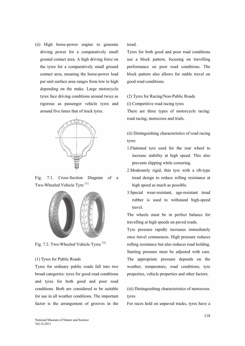
118 National Museum of Nature and Science Vol.16,2011
(ii) High horse-power engine to generate
driving power for a comparatively small
ground contact area. A high driving force on
the tyres for a comparatively small ground
contact area, meaning the horse-power load
per unit surface area ranges from low to high
depending on the make. Large motorcycle
tyres face driving conditions around twice as
rigorous as passenger vehicle tyres and
around five times that of truck tyres.
Fig. 7.1. Cross-Section Diagram of a
Two-Wheeled Vehicle Tyre 11)
Fig. 7.2. Two-Wheeled Vehicle Tyres 12)
(1) Tyres for Public Roads
Tyres for ordinary public roads fall into two
broad categories: tyres for good road conditions
and tyres for both good and poor road
conditions. Both are considered to be suitable
for use in all weather conditions. The important
factor is the arrangement of grooves in the
tread.
Tyres for both good and poor road conditions
use a block pattern, focusing on travelling
performance on poor road conditions. The
block pattern also allows for stable travel on
good road conditions.
(2) Tyres for Racing/Non-Public Roads
(i) Competitive road racing tyres
There are three types of motorcycle racing:
road racing, motocross and trials.
(ii) Distinguishing characteristics of road racing
tyres
1.Flattened tyre used for the rear wheel to
increase stability at high speed. This also
prevents slipping while cornering.
2.Moderately rigid, thin tyre with a rib-type
tread design to reduce rolling resistance at
high speed as much as possible.
3.Special wear-resistant, age-resistant tread
rubber is used to withstand high-speed
travel.
The wheels must be in perfect balance for
travelling at high speeds on paved roads.
Tyre pressure rapidly increases immediately
once travel commences. High pressure reduces
rolling resistance but also reduces road holding.
Starting pressure must be adjusted with care.
The appropriate pressure depends on the
weather, temperature, road conditions, tyre
properties, vehicle properties and other factors.
(iii) Distinguishing characteristics of motocross
tyres
For races held on unpaved tracks, tyres have a

119 National Museum of Nature and Science Vol.16,2011
block design with most of the tread protruding
out a long way to bite into the ground surface
while running.
To prevent skidding sideways, the front wheel
tyre has a more rib-like block design. The rear
wheel tyre is as thick as possible with low tyre
pressure so as to grip the track surface even on
soft earth (by enlarging the ground contact
area).
As with other tyres mentioned above, there is a
transition to radial tyres as development
continues.
7.3. Improved Friction Performance on
Snow and Ice
7.3.1. Studless Tyres
Studless tyres are a category of tyre developed
out of conditions in northern Japan. Developed
as a result of dust problems caused by spiked
tyres in high-traffic snow areas, these tyres
pioneered new areas of winter performance
technology, particularly low-temperature
rubber performance.
While spiked tyres used on cars in northern
winters are popular due to their capacity to
maintain high running stability on snow and ice,
dust issues in the 1980s saw local authorities
and other groups actively campaigning against
them.
Fig. 7.3 shows the high amount of dust during
winter. Prior to the prohibition on spiked tyres,
the times in which spiked tyres were used
coincided with the dust levels. This was due to
the spikes on the tyres shaving away the road
surface and spreading as dust
Fig. 7.3. Trends in the Amount of Dust Fall in Sendai City and Proportion of Spiked Tyres Fitted 1)
1982 1983 1984 1985 1986
(t/km2/month)
Am
ount
of
dust
fal
l
Pro
port
ion
of s
pike
d ty
res
fitt
ed
Leg
end
Amount of dust fall (in front of prefectural office; removed in September 1985 due to road relocation) Amount of dust fall (Kimachidori Elementary School site; 2.3m above the ground) Amount of dust fall (Chuo 3-chome Agricultural and Forestry Central Bank roof; 15.0m above the ground) Proportion of spiked tyres fitted (in front of City Hall); vehicle base

120 National Museum of Nature and Science Vol.16,2011
In June 1986, arbitration was set up between
residents and the tyre industry. It was decided
that manufacture of spiked tyres would stop at
the end of 1990, while sales would cease at the
end of March 1991. Studless tyre sales volumes
grew rapidly from around 1986, turning the
tables on spiked tyre sales for passenger
vehicles.
Use of studless tyres spread so rapidly that they
accounted for 98% of passenger vehicle tyres
by 1991.
(1) Friction on Ice and Snow
Studless tyre driving and braking power on
snow and ice can be represented as the total of
snow column shearing force FB (the shearing
force on the snow columns formed by snow
pressing into the grooves on the tread pattern),
rubber friction force FC (the friction acting on
the road surface and the pattern surface) and
edge effect FD (the edges of the blocks and
sipes digging into the snow and ice on the road
surface) in Fig. 7.4. Each of these
braking-related shearing forces contributes
differently on snow and ice surfaces.
The capacity of the grooves is related to the
snow and ice shearing force at the point of
departure, while the digging friction is strongly
linked to the edge effect during rolling. If there
are a fixed number of edges, the water repelling
effect and digging in effect can be increased by
facilitating the opening of the sipes (fine
grooves on the tread).
Fig. 7.4. Tyre Friction Contribution Ratios on
Snow and Ice (Schematic Diagram) 2)
(2) Measures to Improve Friction
(i) Adhesion / Traction Force
A method to increase adhesion and traction at
molecular level, such as molecular binding
between the surface of the snow or ice and the
tread rubber. The tyre road contact surface is
increased and special rubber is used. While
making the tread rubber softer has the effect of
increasing the adhesion / traction force (FA), if
it is too soft, the blocks will be lost to
deformation, thereby reducing the friction force.
An optimum firmness is required.
(ii) Digging Friction
Friction force caused by the edges of the blocks
on the tread pattern scratching or breaking the
road surface. While making the blocks smaller
and greater in number increases the number of
edges, this also reduces the rigidity of the
blocks; if the blocks undergo significant
deformation, then the ground contact area
Edge effect
Rubber friction
Snow column shearing force
New
sno
w
Com
pact
ed s
now
Gra
nula
r sn
ow
Com
pact
ed s
now
Sli
pper
y
Ice
chun
ks
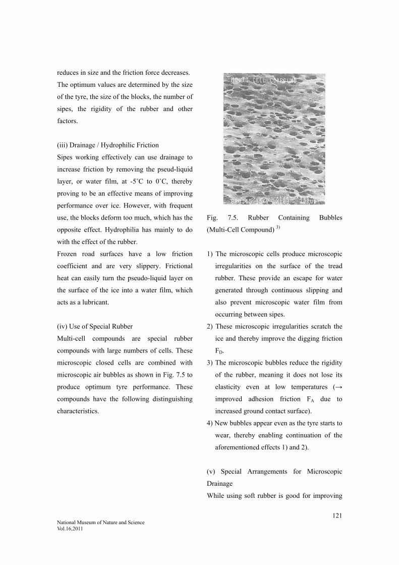
121 National Museum of Nature and Science Vol.16,2011
reduces in size and the friction force decreases.
The optimum values are determined by the size
of the tyre, the size of the blocks, the number of
sipes, the rigidity of the rubber and other
factors.
(iii) Drainage / Hydrophilic Friction
Sipes working effectively can use drainage to
increase friction by removing the pseud-liquid
layer, or water film, at -5˚C to 0˚C, thereby
proving to be an effective means of improving
performance over ice. However, with frequent
use, the blocks deform too much, which has the
opposite effect. Hydrophilia has mainly to do
with the effect of the rubber.
Frozen road surfaces have a low friction
coefficient and are very slippery. Frictional
heat can easily turn the pseudo-liquid layer on
the surface of the ice into a water film, which
acts as a lubricant.
(iv) Use of Special Rubber
Multi-cell compounds are special rubber
compounds with large numbers of cells. These
microscopic closed cells are combined with
microscopic air bubbles as shown in Fig. 7.5 to
produce optimum tyre performance. These
compounds have the following distinguishing
characteristics.
Fig. 7.5. Rubber Containing Bubbles
(Multi-Cell Compound) 3)
1) The microscopic cells produce microscopic
irregularities on the surface of the tread
rubber. These provide an escape for water
generated through continuous slipping and
also prevent microscopic water film from
occurring between sipes.
2) These microscopic irregularities scratch the
ice and thereby improve the digging friction
FD.
3) The microscopic bubbles reduce the rigidity
of the rubber, meaning it does not lose its
elasticity even at low temperatures (→
improved adhesion friction FA due to
increased ground contact surface).
4) New bubbles appear even as the tyre starts to
wear, thereby enabling continuation of the
aforementioned effects 1) and 2).
(v) Special Arrangements for Microscopic
Drainage
While using soft rubber is good for improving
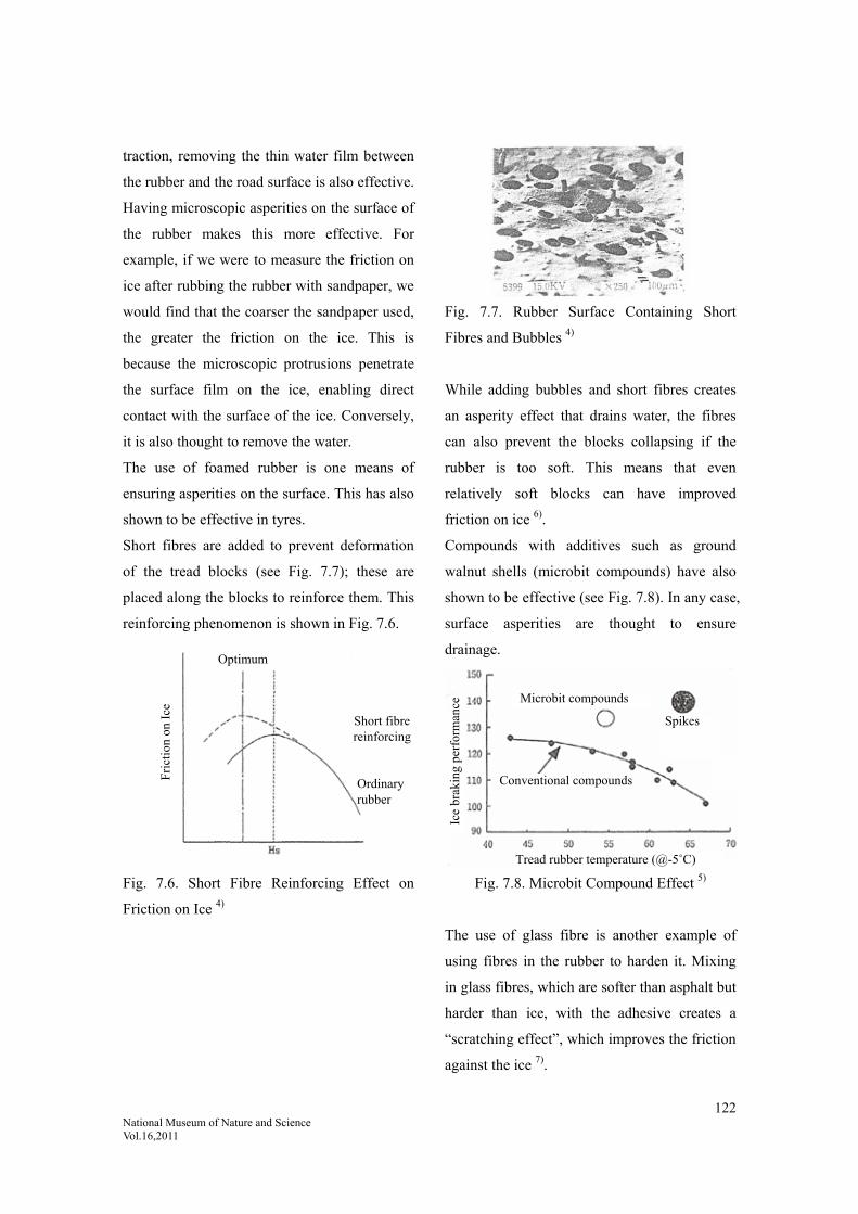
122 National Museum of Nature and Science Vol.16,2011
traction, removing the thin water film between
the rubber and the road surface is also effective.
Having microscopic asperities on the surface of
the rubber makes this more effective. For
example, if we were to measure the friction on
ice after rubbing the rubber with sandpaper, we
would find that the coarser the sandpaper used,
the greater the friction on the ice. This is
because the microscopic protrusions penetrate
the surface film on the ice, enabling direct
contact with the surface of the ice. Conversely,
it is also thought to remove the water.
The use of foamed rubber is one means of
ensuring asperities on the surface. This has also
shown to be effective in tyres.
Short fibres are added to prevent deformation
of the tread blocks (see Fig. 7.7); these are
placed along the blocks to reinforce them. This
reinforcing phenomenon is shown in Fig. 7.6.
Fig. 7.6. Short Fibre Reinforcing Effect on
Friction on Ice 4)
Fig. 7.7. Rubber Surface Containing Short
Fibres and Bubbles 4)
While adding bubbles and short fibres creates
an asperity effect that drains water, the fibres
can also prevent the blocks collapsing if the
rubber is too soft. This means that even
relatively soft blocks can have improved
friction on ice 6).
Compounds with additives such as ground
walnut shells (microbit compounds) have also
shown to be effective (see Fig. 7.8). In any case,
surface asperities are thought to ensure
drainage.
Fig. 7.8. Microbit Compound Effect 5)
The use of glass fibre is another example of
using fibres in the rubber to harden it. Mixing
in glass fibres, which are softer than asphalt but
harder than ice, with the adhesive creates a
“scratching effect”, which improves the friction
against the ice 7).
Optimum
Short fibre reinforcing
Ordinary rubber
Fri
ctio
n on
Ice
Spikes
Microbit compounds
Conventional compounds
Tread rubber temperature (@-5˚C)
Ice
brak
ing
perf
orm
ance
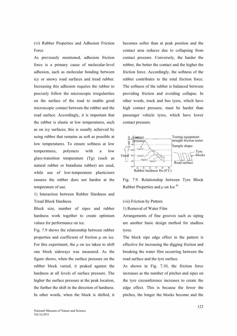
123 National Museum of Nature and Science Vol.16,2011
(vi) Rubber Properties and Adhesion Friction
Force
As previously mentioned, adhesion friction
force is a primary cause of molecular-level
adhesion, such as molecular bonding between
icy or snowy road surfaces and tread rubber.
Increasing this adhesion requires the rubber to
precisely follow the microscopic irregularities
on the surface of the road to enable good
microscopic contact between the rubber and the
road surface. Accordingly, it is important that
the rubber is elastic at low temperatures, such
as on icy surfaces; this is usually achieved by
using rubber that remains as soft as possible at
low temperatures. To ensure softness at low
temperatures, polymers with a low
glass-transition temperature (Tg) (such as
natural rubber or butadiene rubber) are used,
while use of low-temperature plasticisers
ensures the rubber does not harden at the
temperature of use.
1) Interaction between Rubber Hardness and
Tread Block Hardness
Block size, number of sipes and rubber
hardness work together to create optimum
values for performance on ice.
Fig. 7.9 shows the relationship between rubber
properties and coefficient of friction μ on ice.
For this experiment, the μ on ice taken to shift
one block sideways was measured. As the
figure shows, when the surface pressure on the
rubber block varied, it peaked against the
hardness at all levels of surface pressure. The
higher the surface pressure at the peak location,
the further the shift in the direction of hardness.
In other words, when the block is shifted, it
becomes softer than at peak position and the
contact area reduces due to collapsing from
contact pressure. Conversely, the harder the
rubber, the better the contact and the higher the
friction force. Accordingly, the softness of the
rubber contributes to the total friction force.
The softness of the rubber is balanced between
providing friction and avoiding collapse. In
other words, truck and bus tyres, which have
high contact pressure, must be harder than
passenger vehicle tyres, which have lower
contact pressure.
Fig. 7.9. Relationship between Tyre Block
Rubber Properties and μ on Ice 4)
(vii) Friction by Pattern
1) Removal of Water Film
Arrangements of fine grooves such as siping
are another basic design method for studless
tyres.
The block sipe edge effect in the pattern is
effective for increasing the digging friction and
breaking the water film occurring between the
road surface and the tyre surface.
As shown in Fig. 7.10, the friction force
increases as the number of pitches and sipes on
the tyre circumference increases to create the
edge effect. This is because the fewer the
pitches, the longer the blocks become and the
Good
μ on
ice Contact
pressure
Rubber hardness Hs (0˚C)
Testing equipment: straight friction tester
Sample shape:
Tyre blocks
Road surface
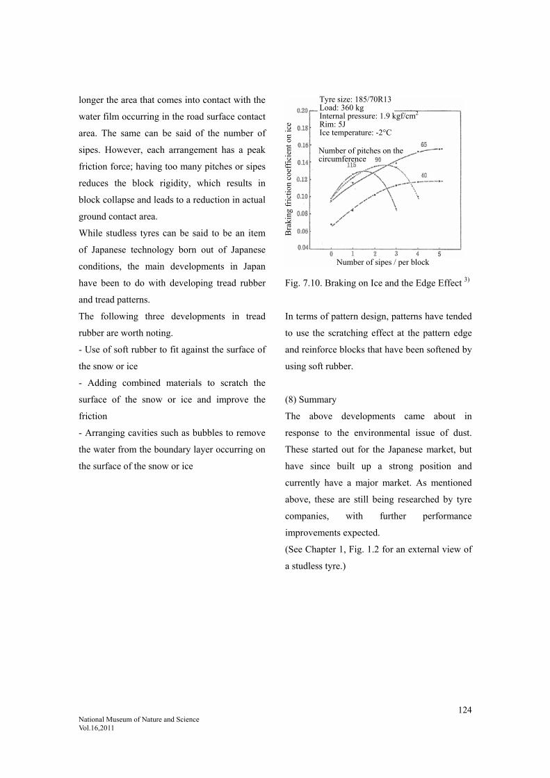
124 National Museum of Nature and Science Vol.16,2011
longer the area that comes into contact with the
water film occurring in the road surface contact
area. The same can be said of the number of
sipes. However, each arrangement has a peak
friction force; having too many pitches or sipes
reduces the block rigidity, which results in
block collapse and leads to a reduction in actual
ground contact area.
While studless tyres can be said to be an item
of Japanese technology born out of Japanese
conditions, the main developments in Japan
have been to do with developing tread rubber
and tread patterns.
The following three developments in tread
rubber are worth noting.
- Use of soft rubber to fit against the surface of
the snow or ice
- Adding combined materials to scratch the
surface of the snow or ice and improve the
friction
- Arranging cavities such as bubbles to remove
the water from the boundary layer occurring on
the surface of the snow or ice
Fig. 7.10. Braking on Ice and the Edge Effect 3)
In terms of pattern design, patterns have tended
to use the scratching effect at the pattern edge
and reinforce blocks that have been softened by
using soft rubber.
(8) Summary
The above developments came about in
response to the environmental issue of dust.
These started out for the Japanese market, but
have since built up a strong position and
currently have a major market. As mentioned
above, these are still being researched by tyre
companies, with further performance
improvements expected.
(See Chapter 1, Fig. 1.2 for an external view of
a studless tyre.)
Tyre size: 185/70R13 Load: 360 kg Internal pressure: 1.9 kgf/cm2 Rim: 5J Ice temperature: -2°C
Number of pitches on the circumference
Number of sipes / per block
Bra
king
fri
ctio
n co
effi
cien
t on
ice

125 National Museum of Nature and Science Vol.16,2011
Cited references:
1) Supaiku Taiya Funjin Hassei Bōshi-hō [Methods to Prevent Dust from Spiked Tyres], Sendai Bar Association,
February 1991, p. 13.
2) Gomu Kōgyō Binran [Rubber Industry Handbook], fourth edition, The Society of Rubber Science and Technology,
Japan, ed., January 1994, p. 754.
3) “Sutaddoresu Taiya no Kaihatsu (Jōyōsha Taiya) [Development of Studless Tyres (Passenger Vehicle Tyres)]”,
Sakamoto, Takao; Hirata, Yasushi: Journal of The Society of Rubber Science and Technology, Japan, Vol. 65, p.
713, 1992.
4) “Sutaddoresu Taiya no Kaihatsu (Torakku oyobi Basu-yō Taiya) [Development of Studless Tyres (Truck and Bus
Tyres)]”, Tomoda, Hajime; Ishikawa, Yasuhiro: Journal of The Society of Rubber Science and Technology, Japan,
Vol. 65, p. 721, 1992.
5) Kawano, Tatsuya; Ueyama, Hiroaki: Journal of The Society of Rubber Science and Technology, Japan, Vol. 69, p.
763, 1996.
6) Ishikawa, Yasuhiro: Journal of The Society of Rubber Science and Technology, Japan, Vol. 70, p. 198, 1997.
7) Sumitomo Gomu Hyakunen-shi [Hundred-year History of Sumitomo Rubber], Sumitomo Rubber Industries, Ltd.,
December 2009, p. 386.
8) Jidōsha-yō Taiya no Kenkyū [Studies on Automobile Tyres], Yokohama Rubber Company, ed., April 1995, p. 47.
9) Jidōsha-yō Taiya no Kenkyū [Studies on Automobile Tyres], Yokohama Rubber Company, ed., April 1995, pp.
56-58.
10) Based on Fig. 2-7-3, Jidōsha-yō Taiya no Kiso to Jissai [Foundation and Reality of Automobile Tyres],
Bridgestone Corporation, Sankaido, 2006, p. 53.
11) Gomu Kōgyō Binran [Rubber Industry Handbook], fourth edition, January 1994, p. 772.
12) Jidōsha-yō Taiya no Kiso to Jissai [Foundation and Reality of Automobile Tyres], Bridgestone Corporation,
Sankaido, 2006, p. 44.

126 National Museum of Nature and Science Vol.16,2011
8. Summary of Technology Progress
Fig. 8.1 shows the progress of the technology.
Tyre technology is divided into broad
categories: “seeds”, or product ideas from tyre
companies to provide technology and develop
products; and “needs”, or demands placed on
tyre companies by society for products in
response to issues that arise. Fig. 8.1 shows that
while the major trends have varied for both
“seeds” and “needs”, up until around the year
2000, “needs” and “seeds” products were
appearing in an almost alternate progression.
“Seeds” products also tended to relate to
structural elements, while “needs” tended to
relate to material elements; accordingly,
structure and materials appeared in alternate
progression.
8.1. Seeds and Needs in Tyre Development
New
materials:
nylon,
SBR
(needs /
material
elements)
Transition
to radial
(seeds /
structural
elements)
Wet
μ/LRR
(needs /
material
elements)
HPT A/S
High
performance
Flattening
(seeds /
structural
elements)
Lightweight /
fuel economy
(CAFE: US fuel
consumption
standards)
Studless
(needs /
material
elements)
Following the post-war introduction of new
materials (nylon, SBR), the transition to radial
tyres began around 1970. During the oil crises,
work reached a global scale on technology to
avoid the trade-off between wet μ (grip on wet
road surfaces) and LRR (low rolling resistance).
Later, once the work on low fuel consumption
as a result of the oil crises eased off, tyre
manufacturers turned their attention to high tyre
performance (flattening). In the 1990s, new
global environmental issues arose, ushering in
an age of “needs”, with very high levels of
demand for ultra-low fuel consumption,
ultra-lightweight tyres, studless tyres and
safety.
High performance tyres (HPT, high grip tyres)
and flattened tyres were recognised to be in a
distinct category from fuel-efficient tyres (wet
μ / LRR) in terms of grip and friction. However,
there was a very high demand for technology
that could avoid a trade-off, providing both
high performance and ultra-low fuel
consumption, as well as being lightweight.
As time progressed on from the 2000s to the
present day, there came a turning point in the
transition from HPT (“seeds”) to lightweight
and fuel economy (major “needs”).
Development issues such as uniformity, noise
and driving ability, which were both “needs”
and “seeds”. Fulfilling all of these criteria at
once was a major hurdle. This was an era of
significant additional required performances;
this required technology that could integrate
both materials and structure.

127 National Museum of Nature and Science Vol.16,2011
This age of major needs required a balance
between multiple performance factors at once.
The design theories that had been proposed by
various Japanese tyre manufacturers from the
1980s onwards proved to be beneficial in
providing a way forward.
Fig. 8.1. Trends in Tyre Technology 1)
Fig. 8.2. Tyre Technology Development by Scale 2)
Needs (material elements)
Seeds (structural elements)
Durability Manoeuvrability Sensation/sensitivity
Wet grip / fuel economy
Fuel economy / lightweight /
studless
Major needs era (environment)
Impa
ct o
f te
chno
logy
Transition to radial
Halogenated butyl liners
Tubeless tyres
High performance (HPT) / all-season
Flattening
Noise and drivingstability
Uniformity
SafetyUltra-long-life
Ultra-low tan δ
Run-flat
Ultra-low fuel
consumption
R&D on new materials
High durability
High age resistanceNo-puncture
tyres Intelligent tyres
(Year)
CAFE (US fuel consumption
standards)
Tyre Technology Development by Scale
Molecular modification technology
Carbon concatenation
Carbon in dispersed state
Material properties
Block pattern
Tyre diameter
Molecular control
Macro control
Transitions in Tyre. “Needs” and “Seeds”

128 National Museum of Nature and Science Vol.16,2011
8.2. Future Integration Methods
For future methods of integration, initiatives
are being carried out as shown in Fig. 8.2.
This is the idea of tyre technology development
by scale. From the micro perspective, tyre
structure fits into the nano-world of molecular
reaction control, while the world of tyre surface
tread design is a world of centimetres, and the
world of rolling resistance – repeated loading
and non-loading due to rotation – is a world of
metres. In other words, tyre performance ranges
in scope from nano-order phenomena to metres.
How all of these factors are controlled, from
molecular order to metre-level order, affects
tyre performance. The way these parameters
are calculated and incorporated will become a
major aspect of performance competition.
Many Japanese tyre manufacturers are basing
their designs on these ideas and are working
effectively in the environmental age.
In this technological environment, the question
remains as to how to balance the many
demands placed on tyres, many of them
mutually exclusive; however, progress has been
made on laying a foundation. This has been
made possible by the large number of
automobile manufacturers in Japan, as well as
the large number of tyre manufacturers. This
has meant that tyre manufacturers have had to
compete with each other to achieve the various
improved performances demanded by many
automobile manufacturers, discovering and
carrying out ways to fulfil these desired
performance factors. Tyre theories were one
result of this adaptability.
The Gomu / Erasutomā to Mirai no Kōtsū
[Rubbers / Elastomers and Future
Transportation] Rubber Technology Forum
tyre team gave the following prediction of
future tyre performance, shown in Fig. 8.3. The
team predicted that by 2030, both wet μ and
rolling resistance will be around 40% better
than they were in 1980.
Progress in Tyre Performance
Fig. 8.3. Predicted Future Tyre Performance 3)
There is a sense that current tyre technology
has been largely established as culmination of
post-war technologies.
Hardly any of the ground-breaking
developments in this technology have come
from Japan, although Japan has mastered and
optimised technology invented overseas to an
advanced level. However, Japan has certainly
reached a high level of tyre technology,
mastering many technologies, balancing them
and taking them to new levels, for example, a
very high level of advancement is evident in the
tyre theories published by various tyre
manufacturers.
While there is currently a sense of plateauing in
technology, when we enter a new growth
T. Haraguchi Toyota at IRC 2005 2030 extrapolated from published data

129 National Museum of Nature and Science Vol.16,2011
period, the challenge for the next generation
will be how to implement uniquely-Japanese
technology. While this can be seen in
embryonic form, some driving force will be
required to develop it.
Cited references:
1) Gomu / Erasutomā to Mirai no Kōtsū [Rubbers / Elastomers and Future Transportation], The Society of Rubber
Science and Technology, Japan Rubber Technology Forum, 30 March 2010, p. 82; a little added.
2) Gomu / Erasutomā to Mirai no Kōtsū [Rubbers / Elastomers and Future Transportation], The Society of Rubber
Science and Technology, Japan Rubber Technology Forum, March 2010, p. 75.
3) Gomu / Erasutomā to Mirai no Kōtsū [Rubbers / Elastomers and Future Transportation], The Society of Rubber
Science and Technology, Japan Rubber Technology Forum, March 2010, p. 81.
Fig. 8.4. Flow Diagram of Tyre Technology
Year
Meiji Taisho Showa Post-War1970 (→ transition to radial) Heisei
Dawn Start of the tyre industry
Start of the age of motorisation
Matuarisation of the age of motorisation
Compounding techniques; the
start of vulcanisation technology
Start of the domestic tyre
industry
Period of introducing new materials
From bias tyres to radial tyres
Stage of maturity of radial tyres
Social changes
Required performance Durability
Spread of highways (post-war)
Wear resistance
Environmental measures
Manoeuvrability Quietness
Noise/vibration Low fuel consumption
/ high friction Safety
Dust pollution
Tyre structure
Pneumatic tyresFabric tyres (1913)
Cord tyres (Palmer type) (1920)
Bias tyres Radial tyres
Tubeless tyres
Flattening
Studless tyres
Run-flat tyres Tread pattern design
Materials
(Rubber) Natural rubber
Tackifiers
Synthetic rubber High cis BR
Halogenated butyl rubber(Reinforcing agents)
Use of carbon black
(Cord) Use of silica
Modified S-SBR
Fabric Tyre cord Cotton Rayon Nylon (1955) Steel cord / polyester
Brass adhesive (1970-)Processing Start of vulcanisation technology
Rubber compound vulcanisation control (Inorganic accelerators, organic accelerators, c. 1920)
RFL adhesive
Manufacturing equipment
Mixer (Banbury)
Rolled rubber/ Rayon
Extruding
Nylon Moulding machine Bias
Bias specificationsVulcaniserRadial
Radial specifications
Steel cord / polyesterIntermeshing mixer

130 National Museum of Nature and Science Vol.16,2011
Fig. 8.5. Changes in Industry Structure due to Innovations in Tyre Technology
Changes in Industry Structure due to Innovations in Tyre Technology
Fun
ctio
n / p
erfo
rman
ce
Dawn Pre-war tyre structure innovations
Vulcanisation technology
Compounding Age of accelerators
Year
Shift in type of business due to discontinuous change Technology innovation due to change in tyre structure + production facilities and equipment technology innovationUse of steel cord, polyester
Continuous change
Continuous change
Transition to radial
New materialsNylon, synthetic rubber
Adhesiveissues
S-SBR for low fuel consumption
Flattening
Silica technology
Noise/vibration
High performance level
Low performance level
Bias Both products andfacilities disappeared
Disappearance of cotton/rayon

131 National Museum of Nature and Science Vol.16,2011
(Appendix) Tyre Technology Timeline
Overall trends; little epoch-making technology from Japan, implemented around 1-10 years behind
the West.
Text in bold represents Japanese technology; underlined text represents epoch-making technology.
Tyre Related Material Related
1769 Steel disc tyre used on Cugnot steam car
wheel (France)
1839 Goodyear discovers vulcanisation
phenomenon (USA)
1835 Solid tyre invented
1842 Hancock solid tyre commercialised (UK) 1843 Hancock obtains patent for vulcanisation
(UK)
1845 Thomson obtains pneumatic tyre patent
(UK)
1863 Michelin established (France)
1871 Macintosh patents hollow solid tyre (UK)
Continental-Gummi established (Germany)
1872 Pirelli established (Italy)
1886 Tsuchiya Rubber Factory established,
Japan’s first rubber company
1888 J.B. Dunlop obtains pneumatic tyre patent
(UK)
Dunlop’s patent commercialised (UK)
Michelin clincher tyre produced (France)
1890 Hartlet clincher tyre patented
Goodrich produces the first American tyre
(USA)
1892 United States Rubber (later Uniroyal)
established (USA)
1893 Solid tyres used on Daimler automobile
(Germany)
B.F. Goodrich automobile tyre prototype (using
tyre fabric) (USA)
1896 Dunlop Holdings established (UK)
1900 Firestone established (USA)
1902 Appearance of tyres with tread pattern

132 National Museum of Nature and Science Vol.16,2011
(USA)
Meiji Rubber produces Japan’s first
automobile tyre
1904 Reinforcing effect of carbon black
discovered
1904 Bead wire straight side tyre (USA) 1905 Oenschlager (USA) discovers organic
vulcanisation accelerators
1908 Palmer-type tyre patented (USA)
1909 Dunlop Rubber (Far East) established in
Kobe (now Sumitomo Rubber)
1910 Appearance of Goodrich cord-type tyre
(USA)
1912 Carbon black used as rubber reinforcing
agent (USA)
1912 B.F. Goodrich established (USA)
1913 Dunlop (Far East) produces the first
domestically-produced tyre
1915 Use of woven cord by J.F. Palmer
1917 Yokohama Rubber founded 1916 First Banbury mixer prototype (USA)
1918 Appearance of pneumatic truck tyres
(USA)
1920 Pirelli produces cord tyres (Italy) 1924 Discovery of anti-ageing agents
1921 Yokohama Rubber produces Japan’s
first cord tyre
1926 Toyobo produces Japan’s first tyre cord
1923 Low-pressure tyre (balloon) developed
(18-30psi vs 20-55psi)
1928 Motorcycle tyres standardised in the USA
1929 Michelin railcar tyre prototype (France)
1930 Bridgestone produces Japan’s first tyre
using domestic technology (by Nihon Tabi)
1931 Bridgestone established
Michelin railcar tyre announced (France)
1930 DuPont succeeds in commercialising
synthetic rubber
1932 Agricultural and construction machinery
tyres standardised in the USA
1934 Michelin commences research on the
application of steel cord for truck tyres (France)
1935 Synthetic rubbers Buna S and Buna N
produced (Germany)
Carothers invents Nylon 66
1937 Michelin announces steel cord tyre (bias) 1936 Japanese companies produce rayon tyre

133 National Museum of Nature and Science Vol.16,2011
(France) prototype
1938 Reinforced rayon tyre appears in the USA 1939 Schlank invents Nylon 6
1940 Butyl tube prototyping begins (USA) 1939 RFL adhesion discovered (USA)
1942 Military nylon tyre prototype (USA) 1940 Butyl rubber (IIR) announced (USA)
1941 Synthetic rubber GR-S production expands
1943 Toyo Tire & Rubber established
1944 Dai-Nippon Aircraft Tyres (later Ohtsu
Tire and Rubber) established
1946 Steel radial tyre patented and production
commences (France)
1947 Tubeless tyre invented (USA)
1948 Michelin enters commercial radial tyre
production (France)
1949 Nitto Tyres (later Ryoto Tyres) founded 1950 Use of SBR begins in Japan
Use of reinforced rayon cord begins
Oil-extended SBR commercialised (USA)
Nippon Zeon founded
1951 Pirelli releases a radial tyre (Italy)
First rayon tyre produced in Japan
1952 Ziegler catalyst invented (Germany)
1954 IR (polyisoprene) successfully synthesised
(USA)
1955 Tubeless tyres adopted on new
automobiles (USA)
Tubeless tyre production starts in Japan
1955 BR (polybutadiene) synthesis announced
(USA)
First use of nylon cord
1956 Use of snow tyres spreads in Europe
1958 Nylon tyres produced
Snow tyres appear in Japan
1957 Japan Synthetic Rubber founded
1960 Radial tyre prototype (Japan)
Snow tyre production begins (Japan)
1958 Japan’s first synthetic rubber
successfully commercialised
1960 Halogenated butyl rubber appears (USA)
1962 Polyester tyre cord becomes the norm
(USA)
Steel cord tyre produced (Japan)
1962 Polyester cord becomes popular (USA)
Successful polyester fibre production
1963 First exports by Bridgestone to Malaysia
and Singapore (later withdrawn)
1964 Flattened tyre (LSH70 %) first used (USA)

134 National Museum of Nature and Science Vol.16,2011
Spiked tyre produced (Japan)
Okamoto Riken enters the tyre business
Belted bias tyres appear around this time (USA)
1966 Polyester tyres fitted to new vehicles
(USA)
1967 Polyester tyres fitted to new vehicles
(Japan)
1967 Fibreglass cord first used (USA)
1968 FMVSS come into force (also related to
tyres) (USA)
Belted bias tyres produced (USA)
Radial tyres fitted to new vehicles (Japan)
1969 Belted bias tyres produced (Japan)
1970 Steel radial tyres produced (Japan)
1972 JATMA “Automotive Tyre Safety
Standards” issued (Japan)
1972 Aramid cord used in tyres (USA)
1973 TGS (safety tyre) prototype (Japan)
1975 ECE30 safety standards start (Europe)
Puncture sealing tyres produced (Japan)
1977 Obsolete tyre grinding facility
completed (Japan)
Japan joins ISO and starts being active
1978 Use of obsolete tyres as fuel for cement
kilns (Japan)
JIS standard D4320 incorporates safety
standards such as dynamic tyre testing
Fuel efficient tyres (1979 energy crisis)
HPT tyres
1983 Run-flat tyres
1986 Studless tyres increase in sales
End of 1990 Spiked tyre production ceases;
sales cease at the end of March 1991
1980s-1990s Japanese companies publish tyre
theories
Early 1990s Michelin announced green tyres
Since these contained silica, silica began to be

135 National Museum of Nature and Science Vol.16,2011
used around the world, particularly in passenger
vehicles; progress was also made on related
processing technology.
2000- Popularisation of run-flat tyres
(side-reinforced)
Cited references for the table above:
The above table was created using references from the following sources, among others.
- Hattori, Rokuro: Taiya no Hanashi [The Story of the Tyre], Taiseisha, June 1992, pp.
229-233.
- Jidōsha Taiya no Kenkyū [Studies on Automobile Tyres], Yokohama Rubber
Company, ed., Sankaido, April 1995, p. 4.
- Buridjisuton Nanajūgo-nen-shi [The 75-Year History of Bridgestone], Bridgestone
Corporation, May 2008.
- Sumitomo Gomu Hyakunen-shi [Hundred-year History of Sumitomo Rubber],
Sumitomo Rubber Industries, Ltd., December 2009.
- Tōyō Gomu Kōgyō Gojūnen-shi [The Fifty-Year History of Toyo Rubber], Toyo Tire
& Rubber, 21 March 1996.
- 80 Shūnen Kinen We Tokubetsu-gō [80-Year Anniversary We Special Edition],
Yokohama Rubber Company, 13 October 1997.
Acknowledgements:
The author expresses sincere gratitude for the wealth of technical information and advice received
from the following persons during the writing of this Systematic Review of Tyre Technology report.
Toyota Automobile Museum Takahiko Sugiura, Kiyoshi Koshimizu
Nichias Corporation Hitoshi Yamada
JATMA Takehito Kondo
Bridgestone Corporation Yasushi Hirata, Keizo Akutagawa, Yuta Mizuno
BRIDGESTONE TODAY
Rubber and Tyre Museum
Isao Ito
Sumitomo Rubber Industries Kosaburo Nasaseko, Yasushi Niimura
Toyo Tire & Rubber Company Kenji Komamizu, Yukinori Morikawa
Yokohama Rubber Company Toshihiko Suzuki, Hideo Kai, Kiyomi Ishikawa,
Masataka Koishi
Yokohama Technical Research team
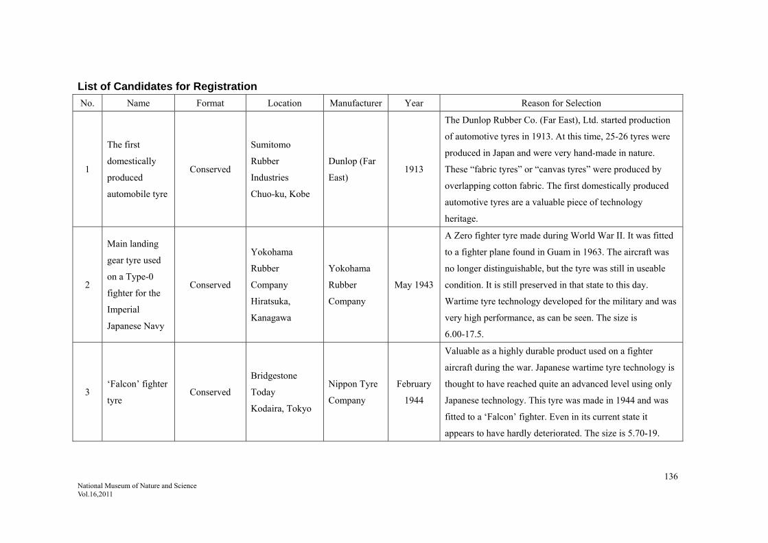
136 National Museum of Nature and Science Vol.16,2011
List of Candidates for Registration
No. Name Format Location Manufacturer Year Reason for Selection
1
The first
domestically
produced
automobile tyre
Conserved
Sumitomo
Rubber
Industries
Chuo-ku, Kobe
Dunlop (Far
East) 1913
The Dunlop Rubber Co. (Far East), Ltd. started production
of automotive tyres in 1913. At this time, 25-26 tyres were
produced in Japan and were very hand-made in nature.
These “fabric tyres” or “canvas tyres” were produced by
overlapping cotton fabric. The first domestically produced
automotive tyres are a valuable piece of technology
heritage.
2
Main landing
gear tyre used
on a Type-0
fighter for the
Imperial
Japanese Navy
Conserved
Yokohama
Rubber
Company
Hiratsuka,
Kanagawa
Yokohama
Rubber
Company
May 1943
A Zero fighter tyre made during World War II. It was fitted
to a fighter plane found in Guam in 1963. The aircraft was
no longer distinguishable, but the tyre was still in useable
condition. It is still preserved in that state to this day.
Wartime tyre technology developed for the military and was
very high performance, as can be seen. The size is
6.00-17.5.
3 ‘Falcon’ fighter
tyre Conserved
Bridgestone
Today
Kodaira, Tokyo
Nippon Tyre
Company
February
1944
Valuable as a highly durable product used on a fighter
aircraft during the war. Japanese wartime tyre technology is
thought to have reached quite an advanced level using only
Japanese technology. This tyre was made in 1944 and was
fitted to a ‘Falcon’ fighter. Even in its current state it
appears to have hardly deteriorated. The size is 5.70-19.

137 National Museum of Nature and Science Vol.16,2011
National Museum of Nature and Science Systematic Examination of Technology Report, Vol. 16 March 31, 2011 Editor: National Museum of Nature and Science (Independent Administrative Institution) Center of the History of Japanese Industrial Technology (Under charge of: coordinating editor: Takayuki Nagata; editor: Toshihiko Okura; English version: Osamu Kamei) Publisher: National Museum of Nature and Science (Independent Administrative Institution) 7-20 Ueno Park, Taito-ku, Tokyo 110-8718 Tel: 03-3822-0111 Japanese issue; Design and Printing: J.Spark Co., Ltd.