Embed Size (px)
Citation preview


Table of contents
Chapter 1: Review of Thermodynamic Principles Chapter 2: Steam Power Plants Chapter 3: Steam Turbines and Auxiliaries Chapter 4: Turbine Governing Systems Chapter 5: Steam Chests and Valves Chapter 6: Turbine Protective Devices Chapter 7: Turbine Instrumentation Chapter 8: Lubrication Systems Chapter 9: Gland Sealing System Chapter 10: An Overview of Gas Turbines Chapter 11: Gas Turbine Compressors Chapter 12: Gas Turbine Combustors Chapter 13: Axial-Flow Turbines Chapter 14: Gas Turbine Materials Chapter 15: Gas Turbine Lubrication and Fuel Systems Chapter 16: Gas Turbine Bearings and Seals Chapter 17: Gas Turbine Instrumentation and Control Systems Chapter 18: Gas Turbine Performance Characteristics Chapter 19: Gas Turbine Operating and Maintenance Considerations Chapter 20: Gas Turbine Emission Guidelines and Control Methods Chapter 21: Combined Cycles Chapter 22: Selection Considerations of Combined Cycles and Cogeneration Plants Chapter 23: Applications of Cogeneration and Combined-Cycle Plants Chapter 24: Cogeneration Application Considerations Chapter 25: Economic and Technical Considerations for Combined-Cycle Performance -- Enhancement Options Chapter 26: Fundamentals of Electrical Systems Chapter 27: Introduction to Machinery Principles Chapter 28: Transformers Chapter 29: Transformer Components and Maintenance Chapter 30: Ac Machine Fundamentals Chapter 31: Synchronous Generators Chapter 32: Generator Components, Auxiliaries, and Excitation Chapter 33: Generator Testing, Inspection, and Maintenance Frequently Asked Questions Index

REVIEW OF THERMODYNAMICPRINCIPLES
The design, operation, and performance of electricity-generating power plants are based onthermodynamic principles.1,2
THE FIRST LAW OF THERMODYNAMICS
The first law of thermodynamics is the law of conservation of energy. It states that energycan be neither created nor destroyed. The energy of a system undergoing change (process)can vary by exchange with the surroundings. However, energy can be converted from oneform to another within that system.
A system is a specified region, not necessarily of constant volume or fixed boundaries,where transfer and conversions of energy and mass are taking place. An open system is onewhere energy and mass cross the boundaries of the system. A steady-state open system, alsocalled the steady-state, steady-flow (SSSF) system, is a system where mass and energyflows across its boundaries do not vary with time, and the mass within the system remainsconstant.
An SSSF system is shown in Fig. 1.1.The first-law equation for that system is
PE1 � KE1 � IE1 � FE1 � �Q � PE2 � KE2 � IE2 � FE2 � �Wsf (1.1)
where PE � potential energy [� mzg/gc, where m � mass of quantity of fluid enteringand leaving the system, z � elevation of station 1 or 2 above a datum, g � gravitational acceleration, and gc � gravitational conversion factor(32.2 lbm � ft/(lbf � s2) or 1.0 kg � m/(N � s2)].
KE � kinetic energy (� mVs2/2gc), where Vs � velocity of the mass.
IE � internal energy (� U) . The internal energy is a sole function of temperaturefor perfect gases and a strong function of temperature and weak function ofpressure for nonperfect gases, vapors, and liquids. It is a measure of theinternal (molecular) activity and interaction of the fluid.
FE � flow energy (� PV � Pmv) . The flow energy or flow work is the workdone by the flowing fluid to push a mass m into or out of the system.
�Q � net heat added [� QA � |Qr|, where QA � heat added and Qr � heat rejectedacross system boundaries; �Q � mcn (T2 � T1), where cn � specific heatthat depends upon the process taking place between 1 and 2. Values of cnvary with the process (refer to Table 1.1)].
CHAPTER 1
1.1
Source: POWER GENERATION HANDBOOK
Downloaded from Digital Engineering Library @ McGraw-Hill (www.digitalengineeringlibrary.com)Copyright © 2004 The McGraw-Hill Companies. All rights reserved.
Any use is subject to the Terms of Use as given at the website.

�Wsf � net steady-flow mechanical work done by the system [� Wby � |Won|, whereWby � work done by system (positive) and Won � work done on system (negative)] .
�Wsf � � �2
1
V � dP (1.2)
A relationship between P and V is required. The most general relationship is given by
PVn � constant (1.3)
where n is called the polytropic exponent. It varies between zero and infinity. Its value forcertain processes is given in Table 1.1. The first-law equation becomes
� � u1 � P1v1 � �q � � � u2 � P2v2 � �Wsf (1.4)
where u � U/m (specific internal energy), and v � V/m (specific volume). A list of com-mon thermodynamic symbols is presented in Table 1.2.
ENTHALPY
Enthalpy is defined as
H � U � PV or h � u � Pv
and the first law becomes
V 2s2�
2gc
z2g�gc
V 2s1�
2gc
z1g�gc
1.2 CHAPTER ONE
FIGURE 1.1 Schematic of a steady-state, steady-flow (SSSF) system with one inlet and one outlet.
TABLE 1.1 Values of cn and n for Various Processes
Process cn n
Constant pressure cp 0Constant temperature ∞ 1
Adiabatic reversible 0 k �
Constant volume cv ∞Polytropic cv 0 � ∞k � n
�1 � n
cp�cv
REVIEW OF THERMODYNAMIC PRINCIPLES
Downloaded from Digital Engineering Library @ McGraw-Hill (www.digitalengineeringlibrary.com)Copyright © 2004 The McGraw-Hill Companies. All rights reserved.
Any use is subject to the Terms of Use as given at the website.

� � H1 � �Q � � � H2 � �Wsf (1.5)
Enthalpies and internal energies are properties of the fluid. This means that each wouldhave a single value at any given state of the fluid. The specific heat at constant volume is
cv � � �v
(1.6)
The specific heat at constant pressure is
cp � � �p
(1.7)
cp � cv � R
where R is the gas constant.For ideal gases:
du � cvdT (1.8)
∂h�∂T
∂u�∂T
mV 2s2�
2gc
mz2g�gc
mV 2s1�
2gc
mz1g�gc
REVIEW OF THERMODYNAMIC PRINCIPLES 1.3
TABLE 1.2 Some Common Thermodynamic Symbols
cp � specific heat at constant pressure, Btu/(lbm � °F) [J/(kg � K)]cv � specific heat at constant volume, Btu/(lbm � °F) [J/(kg � K)]h � specific enthalpy, Btu/lbm (J/kg)H � total enthalpy, Btu (J)J � energy conversion factor � 778.16 ft � lbf/Btu (1.0 N m/J)M � molecular mass, lbm/lb � mol or kg/kg � moln � polytropic exponent, dimensionlessP � absolute pressure (gauge pressure � barometric pressure), lbf/ft
2; unit may be lbf/in2 (com-
monly written psia, or Pa)Q � heat transferred to or from system, Btu or J, or Btu/cycle or J/cycleR � gas constant, lbf � ft/(lbm � °R) or J/(kg � K) � R�/MR� � universal gas constant � 1.545.33, lbf � ft/(lb � mol � °R) or 8.31434 � 103 J/(kg � mol � K)s � specific entropy, Btu/(lbm � °R) or J/(kg � K)S � total entropy, Btu/°R or J/kgt � temperature, °F or °CT � temperature on absolute scale, °R or Ku � specific internal energy, Btu/lbm or J/kgU � total internal energy, Btu or Jv � specific volume, ft3/lbm or m3/kgV � total volume, ft3 or m3
W � work done by or on system, lbf � ft or J, or Btu/cycle or J/cyclex � quality of a two-phase mixture � mass of vapor divided by total mass, dimensionlessk � ratio of specific heats, cp/cv, dimensionless� � efficiency, as dimensionless fraction or percent
Subscripts used in vapor tables
f refers to saturated liquidg refers to saturated vaporfg refers to change in property because of change from saturated liquid to saturated vapor
REVIEW OF THERMODYNAMIC PRINCIPLES
Downloaded from Digital Engineering Library @ McGraw-Hill (www.digitalengineeringlibrary.com)Copyright © 2004 The McGraw-Hill Companies. All rights reserved.
Any use is subject to the Terms of Use as given at the website.

dh � cpdT
where cv and cp are constants. They are independent of temperature for monatomic gasessuch as He. They increase with temperature for diatomic gases such as air and more so fortriatomic gases such as CO2 and so forth. Therefore, for constant specific heats or for smallchanges in temperature:
�u � cv�T (1.9)
�h � cp�T
Following are some examples:
● For a steam generator, �Wsf � 0, PE2 � PE1 is negligible, KE2 � KE1 is negligible, �Q � H2 � H1, and �q � h2 � h1.
● For gas or steam turbine, �Q � negligible, PE2 � PE1 is negligible, KE2 � KE1 is neg-ligible, and �Wsf � H1 � H2.
● For water (or incompressible fluid) pump, �Q is negligible, PE2 � PE1 is negligible, KE2 �KE1 is negligible, U2 � U1, V2 � V1 � V (incompressible fluid), and �Wsf � FE1 � FE2 �V(P1 � P2).
CLOSED SYSTEM
In the open system, mass crosses the boundaries. In the closed system, only energy crossesthe boundaries. The first law for the closed system becomes
�Q � �U � �Wnf (change with time, before and after the process
has taken place) (1.10)
�Wnf is called the no-flow work. It is given by
�Wnf � �2
1
PdV (1.11)
THE CYCLE
To convert energy from heat to work on a continuous basis, one needs to operate a cycle.A cycle is a series of processes that begins and ends at the same state and can be repeatedindefinitely. Figure 1.2 illustrates an ideal diesel cycle.
Process 1 to 2. Ideal and adiabatic (no heat exchanged) compression
Process 2 to 3. Heat adidtion at constant pressure
Process 3 to 4. Ideal and adiabatic expansion process
Process 4 to 1. Constant-volume heat rejection
The first law becomes
�Qnet � QA � |QR| � �Wnet (1.12)
1.4 CHAPTER ONE
REVIEW OF THERMODYNAMIC PRINCIPLES
Downloaded from Digital Engineering Library @ McGraw-Hill (www.digitalengineeringlibrary.com)Copyright © 2004 The McGraw-Hill Companies. All rights reserved.
Any use is subject to the Terms of Use as given at the website.

PROPERTY RELATIONSHIPS
Perfect Gases
Property relationships for perfect gases for different processes are given in Table 1.3 A per-fect (or ideal) gas is one that, at any state, obeys the equation of state for perfect gases:
Pv � RT (1.13)
Imperfect Gases
A nonperfect gas is one in which the molecules are close enough to exert forces on eachother as when a perfect gas is highly compressed and/or highly cooled with respect to itscritical conditions. The behavior of imperfect gases is given by
Pv � ZRT (1.14)
where Z is the compressibility factor that depends on P, T, and the gas itself.
VAPOR-LIQUID PHASE EQUILIBRIUM IN A PURESUBSTANCE
Consider a piston-cylinder arrangement containing 1 kg of water (refer to Fig. 1.3). Supposethe initial pressure and temperature inside the cylinder are 0.1 MPa and 20°C. As heat is trans-ferred to the water, the temperature increases while the pressure remains constant. When thetemperature reaches 99.6°C, additional heat transfer results in a change of phase, as indicatedin Fig. 1.3 (b). Some of the liquid becomes vapor. However, during this process, both tem-perature and pressure remain constant, but the specific volume increases considerably. When
REVIEW OF THERMODYNAMIC PRINCIPLES 1.5
FIGURE 1.2 Pressure-volume (a) and temperature-entropy (b) dia-grams of an ideal diesel cycle.
REVIEW OF THERMODYNAMIC PRINCIPLES
Downloaded from Digital Engineering Library @ McGraw-Hill (www.digitalengineeringlibrary.com)Copyright © 2004 The McGraw-Hill Companies. All rights reserved.
Any use is subject to the Terms of Use as given at the website.

TA
BLE
1.3
Perf
ect-
Gas
Rel
atio
nshi
ps (
Con
stan
t Spe
cifi
c H
eats
)
Proc
ess
P, v
, Tre
latio
nshi
psu 2
�u 1
h 2�
h 1s 2
�s 1
w(n
onfl
ow)
w(f
low
)Q
Isot
herm
alT
�co
nsta
ntP
1/P
2�
v 2/v
10
0(R
/J)l
n(v 2
/v1)
(P1v
1/J)
ln(v
2/v 1
)(P
1v1/
J)ln
(v2/v
1)(P
1v1/
J)ln
(v2/v
1)
Con
stan
t pre
ssur
eP
�co
nsta
ntT
2/T
1�
v 2/v
1c v
(T2
�T
1)c p
(T2
�T
1)c p
ln(T
2/T
1)P
(v2
�v 1
)/J
0c p
(T2
�T
1)
Con
stan
t vol
ume
v�
cons
tant
T2/T
1�
P2/P
1c v
(T2
�T
1)c p
(T2
�T
1)c v
ln(T
2/T
1)0
v(P
1�
P2)
/Jc v
(T2
�T
1)
Isen
trop
ics
�co
nsta
nt(A
diab
atic
rev
ersi
ble)
P1v
1k�
P2v
2kc v
(T2
�T
1)c p
(T2
�T
1)0
0T
2/T
1�
(v1/
v 2)k
�1
T2/T
1�
(P2/
P1)
(k�
1)/k
Thr
ottli
ngh
�co
nsta
nt0
0(R
/J)l
n(v 2
/v1)
00
0T
�co
nsta
ntP
1/P
2�
v 2/v
1
Poly
trop
icP
1v1n
�P
2v2n
c v(T
2�
T1)
c p(T
2�
T1)
c vln
(P2/
P1)
T2/T
1�
(v1/
v 2)n�
1�
c pln
(v2/v
1)c v�
�(T2
�T
1)T
2/T
1�
(P2/P
1)(n
�1)
/n
k�
n� 1
�n
n(P
2v2
�P
1v1)
��
J(1
�n)
(P2v
2�
P1v
1)�
�J(
1�
n)
k(P
2v2
�P
1v1)
��
J(1
�k)
(P2v
2�
P1v
1)�
�J(
1�
k)
1.6
REVIEW OF THERMODYNAMIC PRINCIPLES
Downloaded from Digital Engineering Library @ McGraw-Hill (www.digitalengineeringlibrary.com)Copyright © 2004 The McGraw-Hill Companies. All rights reserved.
Any use is subject to the Terms of Use as given at the website.

all the liquid has vaporized, additional heattransfer results in increase in both tempera-ture and specific volume of the vapor.
The saturation temperature is the tem-perature at which vaporization occurs at agiven pressure. This pressure is called thesaturation pressure for the given tempera-ture. For example, for water at 0.1 MPa, thesaturation temperature is 99.6°C.
For a pure substance, there is a relation-ship between the saturation temperature andthe saturation pressure. Figure 1.4 illus-trates this relationship. The curve is calledthe vapor-pressure curve.
If a substance exists as liquid at the saturation temperature and pressure, it is called sat-urated liquid. If the temperature of the liquid is lower than the saturation temperature forthe existing pressure, it is called subcooled liquid (or compressed liquid, implying that thepressure is greater than the saturation pressure for the given temperature).
When a substance exists as part liquid and part vapor at the saturation temperature andpressure, its quality (x) is defined as the ratio of the vapor mass to the total mass.
If the substance exists as vapor at the saturation temperature, it is called saturated vapor.When the vapor is at a temperature greater than the saturation temperature (for the existingpressure), it is called superheated vapor. The temperature of a superheated vapor mayincrease while the pressure remains constant.
Figure 1.5 illustrates a temperature-volume diagram for water showing liquid and vaporphases. Note that when the pressure is 1 MPa, vaporization (saturation temperature) beginsat 179.9°C. Point G is the saturated-vapor state, and line GH represents the constant-pres-sure process in which the steam is superheated. A constant pressure of 10 MPa is repre-sented by line IJKL. The saturation temperature is 311.1°C. Line NJFB represents thesaturated-liquid line, and line NKGC represents the saturated-vapor line.
At a pressure 22.09 MPa, represented by line MNO, we find, however, that there is noconstant-temperature vaporization process. Instead, there is one point, N, where the curvehas a zero slope. This point is called the critical point. At this point, the saturated-liquid andsaturated-vapor states are identical.
The temperature, pressure, and specific volume at the critical point are called the criti-cal temperature, critical pressure, and critical volume. The critical-point data for somesubstances are presented in Table 1.4.
REVIEW OF THERMODYNAMIC PRINCIPLES 1.7
FIGURE 1.3 Constant-pressure change from liquid to vapor phase for a pure substance. (a)Liquid water, (b) liquid water–water vapor, (c) water vapor.
FIGURE 1.4 Vapor-pressure curve of a puresubstance.
REVIEW OF THERMODYNAMIC PRINCIPLES
Downloaded from Digital Engineering Library @ McGraw-Hill (www.digitalengineeringlibrary.com)Copyright © 2004 The McGraw-Hill Companies. All rights reserved.
Any use is subject to the Terms of Use as given at the website.
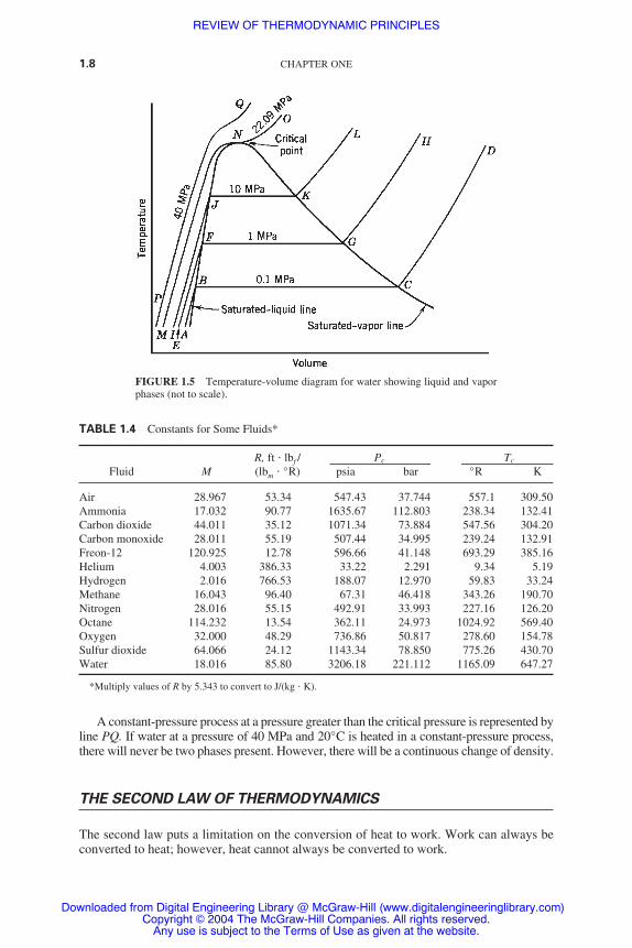
A constant-pressure process at a pressure greater than the critical pressure is represented byline PQ. If water at a pressure of 40 MPa and 20°C is heated in a constant-pressure process,there will never be two phases present. However, there will be a continuous change of density.
THE SECOND LAW OF THERMODYNAMICS
The second law puts a limitation on the conversion of heat to work. Work can always beconverted to heat; however, heat cannot always be converted to work.
1.8 CHAPTER ONE
FIGURE 1.5 Temperature-volume diagram for water showing liquid and vaporphases (not to scale).
TABLE 1.4 Constants for Some Fluids*
R, ft � lbf / Pc Tc
Fluid M (lbm � °R) psia bar °R K
Air 28.967 53.34 547.43 37.744 557.1 309.50Ammonia 17.032 90.77 1635.67 112.803 238.34 132.41Carbon dioxide 44.011 35.12 1071.34 73.884 547.56 304.20Carbon monoxide 28.011 55.19 507.44 34.995 239.24 132.91Freon-12 120.925 12.78 596.66 41.148 693.29 385.16Helium 4.003 386.33 33.22 2.291 9.34 5.19Hydrogen 2.016 766.53 188.07 12.970 59.83 33.24Methane 16.043 96.40 67.31 46.418 343.26 190.70Nitrogen 28.016 55.15 492.91 33.993 227.16 126.20Octane 114.232 13.54 362.11 24.973 1024.92 569.40Oxygen 32.000 48.29 736.86 50.817 278.60 154.78Sulfur dioxide 64.066 24.12 1143.34 78.850 775.26 430.70Water 18.016 85.80 3206.18 221.112 1165.09 647.27
*Multiply values of R by 5.343 to convert to J/(kg � K).
REVIEW OF THERMODYNAMIC PRINCIPLES
Downloaded from Digital Engineering Library @ McGraw-Hill (www.digitalengineeringlibrary.com)Copyright © 2004 The McGraw-Hill Companies. All rights reserved.
Any use is subject to the Terms of Use as given at the website.

The portion of heat that cannot be converted to work is called unavailable energy. Itmust be rejected as low-grade heat after work is generated.
The second law states that the thermal efficiency of converting heat to work, in a powerplant, must be less than 100 percent. The Carnot cycle represents an ideal heat engine thatgives the maximum-value of that efficiency between any two temperature limits. In a steamor gas power plant, heat is received from a high-temperature reservoir (a reservoir is asource of heat or heat sink large enough that it does not undergo a change in temperaturewhen heat is added or subtracted from it), such as steam generators or combustors.
Heat is also rejected in a steam or gas power plant to a low-temperature reservoir, suchas condensers or the environment. The work produced in the steam or gas power plant isthe difference between the heat received from the high-temperature reservoir and the heatrejected to the low-temperature reservoir.
THE CONCEPT OF REVERSIBILITY
Sadi Carnot introduced the concept of reversibility and laid the foundations of the secondlaw. A reversible process, also called an ideal process, can reverse itself exactly by fol-lowing the same path it took in the first place. Thus, it restores to the system or the sur-roundings the same heat and work previously exchanged.
In reality, there are no ideal (reversible) processes. Real processes are irreversible.However, the degree of irreversibility varies between processes.
There are many sources of irreversibility in nature. The most important ones are fric-tion, heat transfer, throttling, and mixing. Mechanical friction is one in which mechanicalwork is dissipated into a heating effect. One example would be a shaft rotating in a bear-ing. It is not possible to add the same heat to the bearing to cause rotation of the shaft.
An example of fluid friction is when the fluid expands through the turbine, under-going internal friction. This friction results in the dissipation of part of its energy intoheating itself at the expense of useful work. The fluid then does less work and exhaustsat a higher temperature. The more irreversible the process, the more heating effect andthe less the work.
Heat transfer in any form cannot reverse itself. Heat transfer causes a loss of availabil-ity because no work is done between the high- and low-temperature bodies.
EXTERNAL AND INTERNAL IRREVERSIBILITIES
External irreversibilities are those that occur across the boundaries of the system. The pri-mary source of external irreversibility in power systems is heat transfer both at the high-and low-temperature ends.
Internal irreversibilities are those that occur within the boundaries of the system. Theprimary source of internal irreversibilities in power systems is fluid friction in rotarymachines, such as turbines, compressors, and pumps.
THE CONCEPT OF ENTROPY
Entropy is a property (e.g., pressure, temperature, and enthalpy). Entropy is given by theequation
REVIEW OF THERMODYNAMIC PRINCIPLES 1.9
REVIEW OF THERMODYNAMIC PRINCIPLES
Downloaded from Digital Engineering Library @ McGraw-Hill (www.digitalengineeringlibrary.com)Copyright © 2004 The McGraw-Hill Companies. All rights reserved.
Any use is subject to the Terms of Use as given at the website.

�Q � �2
1
TdS (reversible process only) (1.15)
For a reversible, adiabatic process, �Q � 0. Therefore,
��2
1
TdS � 0� → (dS � 0) → (S � constant) (1.16)
Figure 1.6 illustrates a few processes on the temperature-entropy diagram. A reversible adi-abatic process is shown as 1-2s in Fig. 1.6. Assume that the expanding fluid is a perfect gas(the same conclusion can be drawn for vapor or a mixture of liquid and vapor). Lines P1and P2 in Fig. 1.6 are constant-pressure lines (P1 P2). Process 1-2 in Fig. 1.6 illustratesan adiabatic but irreversible process. Irreversibility has manifested itself in an increase intemperature of the gas at P2 (T2 T2s).
1.10 CHAPTER ONE
FIGURE 1.6 Expansion (a) and compression (b) of a gas from P1 to P2on the T-S diagram. Process 1-2s is adiabatic reversible; process 1-2 isadiabatic irreversible; and process 1-2t is throttling.
More irreversible expansion results in greater self-heating of the gas, as shown inprocess 1-2. Therefore, when irreversibility increases in an adiabatic process, the entropyincreases as well. The work produced decreases with an increase in irreversibility.
Process 1-2t is a constant-temperature process (for a gas, it is a constant enthalpy aswell). This is a throttling process, where �H is zero and all the energy is dissipated in fluidfriction. This is the most irreversible process. It creates the most increase in entropy.
The degree of irreversibility for an expansion in a turbine is given by the polytropic tur-bine efficiency, �T (sometimes called the isentropic or adiabatic turbine efficiency). It isequal to the ratio of actual work to ideal work.
The polytropic turbine efficiency is given by
�T � � (1.17)
For constant specific heats
�T � (1.18)T1 � T2�T1 � T2s
h1 � h2�h1 � h2s
H1 � H2�H1 � H2s
REVIEW OF THERMODYNAMIC PRINCIPLES
Downloaded from Digital Engineering Library @ McGraw-Hill (www.digitalengineeringlibrary.com)Copyright © 2004 The McGraw-Hill Companies. All rights reserved.
Any use is subject to the Terms of Use as given at the website.

If the fluid is being compressed [Fig. 1.6 (b)], an adiabatic, reversible compression fol-lows the constant entropy path 1-2s. If the process changes to adiabatic irreversible com-pression, the gas leaves at higher temperature T2.
The fluid in this process absorbs some work input, which is dissipated in fluid friction.The greater the irreversibility, the greater the exit temperature (T2, T2′ T2s) and thegreater the increase in entropy.
Since dh � cpdT for gases, then,
H2′ H2 H2s (1.19)
and the work absorbed in compression |Wc| increases with irreversibility.The degree of irreversibility is given by the compressor efficiency. It is called the poly-
tropic compressor efficiency, �c (sometimes it is called the isentropic or adiabatic com-pressor efficiency). It is equal to the ratio of ideal work to actual work (the reverse of thatof the expansion) and is given by
�c � � (1.20)
For constant specific heats
�c � (1.21)
We can conclude that the change of entropy is a measure of the unavailable energy.Therefore, entropy is a measure of irreversibility. This implies that entropy is a measure ofdisorder. Entropy of the universe is continually increasing and available energy is continu-ally decreasing.
Figure 1.7 illustrates vapor expanding from pressure P1 to pressure P2, where P2 is inthe two-phase region. Even if the exit temperature of the adiabatic reversible and adiabatic
T2s � T1�T2 � T1
h2s � h1�h2 � h1
H2s � H1�H2 � H1
REVIEW OF THERMODYNAMIC PRINCIPLES 1.11
FIGURE 1.7 Expansion fo a vapor from P1 to P2 on the (a) T-s and (b) Mollier (h-s) diagrams. Process 1-2sis adiabatic reversible, and process 1-2 is adiabatic irreversible.
REVIEW OF THERMODYNAMIC PRINCIPLES
Downloaded from Digital Engineering Library @ McGraw-Hill (www.digitalengineeringlibrary.com)Copyright © 2004 The McGraw-Hill Companies. All rights reserved.
Any use is subject to the Terms of Use as given at the website.

irreversible processes is the same, the exit enthalpy is greater in the case of the irreversibleprocess (h2 h2s) and the work is less:
h1 � h2 h1 � h2s (1.22)
The degree of irreversibility is given by the turbine efficiency.
THE CARNOT CYCLE
Sadi Carnot introduced the principles of the second law of thermodynamics, the conceptsof reversibility and cycle. He also proved that the thermal efficiency of a reversible cycleis determined by the temperatures of the heat source and heat sink.
The Carnot cycle is shown in Fig. 1.8 on the P-V and T-S diagrams. It is composed offour processes:
1. Process 1-2. Reversible adiabatic compression
2. Process 2-3. Reversible constant-temperature heat addition
3. Process 3-4. Reversible adiabatic expansion
4. Process 4-1. Reversible constant-temperature heat rejection
Heat addition: QA � TH (S3 � S2) (1.23)
Heat rejection: QR � TL (S1 � S4) (1.24)
Net work: �Wnet � QA � |QR| (1.25)
Thermal efficiency: �th � (1.26)
Thus, the thermal efficiency of the Carnot cycle �c is given by
�c � (1.27)TH � TL�
TH
�Wnet�QA
1.12 CHAPTER ONE
FIGURE 1.8 Carnot cycle on the (a) P-V and (b) T-S diagrams.
REVIEW OF THERMODYNAMIC PRINCIPLES
Downloaded from Digital Engineering Library @ McGraw-Hill (www.digitalengineeringlibrary.com)Copyright © 2004 The McGraw-Hill Companies. All rights reserved.
Any use is subject to the Terms of Use as given at the website.

The thermal efficiency of the Carnot cycle is dependent on the heat source and heat sinktemperatures. It is independent of the working fluid.
Since the Carnot cycle is reversible, it produces the maximum amount of work betweentwo given temperature limits, TH and TL. Therefore, a reversible cycle operating betweengiven temperature limits has the highest possible thermal efficiency of all cycles operatingbetween these same temperature limits. The Carnot cycle efficiency is to be considered anupper efficiency limit that cannot be exceeded in reality.
REFERENCES
1. El-Wakil, M. M., Power Plant Technology, McGraw-Hill, New York, 1984.
2. Van Wylen, J. G., Fundamentals of Classical Thermodynamics, John Wiley & Sons, New York, 1976.
REVIEW OF THERMODYNAMIC PRINCIPLES 1.13
REVIEW OF THERMODYNAMIC PRINCIPLES
Downloaded from Digital Engineering Library @ McGraw-Hill (www.digitalengineeringlibrary.com)Copyright © 2004 The McGraw-Hill Companies. All rights reserved.
Any use is subject to the Terms of Use as given at the website.

REVIEW OF THERMODYNAMIC PRINCIPLES
Downloaded from Digital Engineering Library @ McGraw-Hill (www.digitalengineeringlibrary.com)Copyright © 2004 The McGraw-Hill Companies. All rights reserved.
Any use is subject to the Terms of Use as given at the website.

STEAM POWER PLANTS
THE RANKINE CYCLE
The Rankine cycle is the most widely used cycle for electric power generation. Figure 2.1illustrates a simplified flow diagram of a Rankine cycle. Figure 2.2(a, b) shows the idealRankine cycle on P-v and T-s diagrams. Cycle 1-2-3-4-B-1 is a saturated Rankine cycle(saturated vapor enters the turbine). Cycle 1′-2′-3-4-B-1′ is a superheated Rankine cycle.
The cycles shown are internally reversible. The processes through the turbine and pumpare adiabatic reversible. Hence, vertical on the T-s diagram. There are no pressure losses inthe piping. Line 4-B-1-1′ is a constant-pressure line.
The reversible Rankine cycle has the following processes:
Line 1-2 or 1′-2′. Adiabatic reversible expansion through the turbine. The exhaustvapor at point 2 or point 2′ is usually in the two-phase region.
Line 2-3 or 2′-3. Constant-temperature and, being a two-phase mixture process, con-stant-pressure heat rejection in the condenser.
Line 3-4. Adiabatic reversible compression by the pump of saturated liquid at the con-denser pressure, point 3, to subcooled liquid at the steam generator pressure, point 4.Line 3-4 is vertical on both the P-v and T-s diagrams because the liquid is essentiallyincompressible and the pump is adiabatic reversible.
Line 4-1 or 4-1′. Constant-pressure heat addition in the steam generator. Line 4-B-1-1′is a constant-pressure line on both diagrams. Portion 4-B represents bringing the sub-cooled liquid, point 4, to saturated liquid at point B. Section 4-B in the steam generatoris called an economizer. Portion B-1 represents heating the saturated liquid to saturatedvapor at constant pressure and temperature (being a two-phase mixture), and section B-1in the steam generator is called the boiler or evaporator. Portion 1-1′, in the superheatcycle, represents heating the saturated vapor at point 1 to point 1′. Section 1-1′ in thesteam generator is called a superheater.Following is the thermodynamic analysis based on a unit mass of vapor in the cycle:
Heat added
qA � h1 � h4 Btu/lbm (or J/kg) (2.1)
Turbine work
wT � h1 � h2 Btu/lbm (or J/kg) (2.2)
Heat rejected
|qR| � h2 � h3 Btu/lbm (or J/kg) (2.3)
Pump work
|wp| � h4 � h3 (2.4)
CHAPTER 2
2.1
Source: POWER GENERATION HANDBOOK
Downloaded from Digital Engineering Library @ McGraw-Hill (www.digitalengineeringlibrary.com)Copyright © 2004 The McGraw-Hill Companies. All rights reserved.
Any use is subject to the Terms of Use as given at the website.

Net work
�wnet � (h1 � h2) � (h4 � h3) Btu/lbm (or J/kg) (2.5)
Thermal efficiency
�th � � (2.6)
For small units where P4 is not much larger than P3,
h3 ≈ h4 (2.7)
The pump work is negligible compared with the turbine work, the thermal efficiency (withlittle error) is
(h1 � h2) � (h4 � h3)���(h1 � h4)
�wnet�qA
2.2 CHAPTER TWO
FIGURE 2.1 Schematic flow diagram of a Rankine cycle.
FIGURE 2.2 Ideal Rankine cycles of the (a) P-V and (b) T-s diagrams. Line 1-2-3-4-B-1 � saturated cycle.Line 1′-2′-3-4-B-1′ � superheated cycle. CP � critical point.
STEAM POWER PLANTS
Downloaded from Digital Engineering Library @ McGraw-Hill (www.digitalengineeringlibrary.com)Copyright © 2004 The McGraw-Hill Companies. All rights reserved.
Any use is subject to the Terms of Use as given at the website.

�th � (2.8)
This assumption is not true for modern power plants, where P4 is 1000 psi (70 bar) orhigher, while P3 is about 1 psi (0.07 bar). In this case, the pump work may be obtained byfinding h3 as the saturated enthalpy of liquid at P3 from the steam tables. One can find h4from the subcooled liquid tables at T4 and P4 (assuming that T3 � T4).
An approximation for the pump work may be obtained from the change in flow work:
wp � v3 (P4 � P3) (2.9)
REHEAT
Reheat improves the cycle efficiency. Figures 2.3 and 2.4 illustrate the flow and T-s dia-grams of an internally reversible Rankine cycle (i.e., the process through the turbine andpump is adiabatic and reversible. Also, there is no pressure drop in the cycle). The cyclesuperheats and reheats the vapor. The vapor in the reheat cycle at point 1 is expanded in thehigh-pressure turbine to point 2.
Note: Line ab represents the primary coolant in a counterflow steam generator (the pri-mary heat source is the combustion gases from the steam generator furnace).
The vapor is returned back to the steam generator where it is reheated at constant pressure(ideally) to a temperature near that at point 1. The reheated steam now enters the low-pressureturbine where it expands to the condenser pressure.
In a reheat cycle, heat is added twice: from point 6 to point 1 and from point 2 to point 3.It keeps the boiler-superheat-reheat portion from point 7 to point 3 close to the primaryfluid line ae. This increases the cycle efficiency.
Reheat also produces drier steam at the turbine exhaust (point 4 instead of point 4′).Modern fossil-fueled power plants have at least one stage of reheat. If more than two stagesof reheat are used, cycle complication occurs and the improvement in efficiency does notjustify the increase in capital cost.
h1 � h2�h1 � h3
STEAM POWER PLANTS 2.3
FIGURE 2.3 Schematic of a Rankine cycle with superheat and reheat.
STEAM POWER PLANTS
Downloaded from Digital Engineering Library @ McGraw-Hill (www.digitalengineeringlibrary.com)Copyright © 2004 The McGraw-Hill Companies. All rights reserved.
Any use is subject to the Terms of Use as given at the website.

In some plants, the steam is not reheated in the steam generator. It is reheated in a sep-arate heat exchanger reheater. A portion of the steam at point 1 is used to reheat the steamat point 2. This flow condenses and is sent to the feed water heaters. The reheat cycleinvolves two turbine work terms and two heat addition terms. (Refer to Fig. 2.4.)
WT � (h1 � h2) � (h3 � h4) (2.10)
|Wp| � h6 � h5 (2.11)
�Wnet � (h1 � h2) � (h3 � h4) � (h6 � h5) (2.12)
qA � (h1 � h6) � (h3 � h2) (2.13)
�th � (2.14)
The reheat pressure P2 affects the cycle efficiency. Figure 2.5 illustrates the variation incycle efficiency as a function of the ratio of reheat pressure to initial pressure P2/P1. P1 �2500 psia, T1 � 1000°F, and T3 � 1000°F. If the reheat pressure is too close to the initialpressure, the increase in cycle efficiency is minimal because only a small portion of heat isadded at high temperature.
The optimum reheat efficiency is reached when P2/P1 is between 20 and 25 percent.Lowering the reheat pressure, P2 further causes the efficiency to decrease again (area 2-3-4-4′ decreases if P2 drops below 0.2).
Exhaust steam is drier in a reheat cycle. A superheat-reheat power plant is designatedP1/T1/T3 (e.g., 2500 psi/1000°F/1000°F). Table 2.1 compares the performance of fiveplants. Note the increase in efficiency due to reheating and the significant drop in efficiencycaused by using nonideal fluids.
�Wnet�qA
2.4 CHAPTER TWO
FIGURE 2.4 T-s diagram of Rankine cycle of Fig. 2.3.
STEAM POWER PLANTS
Downloaded from Digital Engineering Library @ McGraw-Hill (www.digitalengineeringlibrary.com)Copyright © 2004 The McGraw-Hill Companies. All rights reserved.
Any use is subject to the Terms of Use as given at the website.

REGENERATION
External irreversibility is caused by the temperature differences between the primary heatsource (combustion gases or primary coolant) and the working fluid. Temperature differ-ences between condensing working fluid and the heat sink fluid (condenser cooling wateror cooling air) also cause external irreversibility.
STEAM POWER PLANTS 2.5
FIGURE 2.5 Effect of reheat-to-initial-pressure ratio on efficiency, high-pressure turbine exit temperature,and low-pressure turbine exit quality. Data for cycle of Fig. 2.7 with initial steam at 2500 psia and 1000°F,and steam reheat to 1000°F (2500/1000/1000).
TABLE 2.1 Steam Power Plant Performance Comparison
Cycle
A B C D ESuperheat 2500 Superheat 2500/ 2500/1000
Data 2500/1000 saturated 1000/668.11 1000/1000 nonideal
Turbine inlet pressure, psia 2500 2500 1000 2500 2500Turbine inlet temperature, °F 1000 668.11 668.11 1000 1000Condenser pressure, psia 1 1 1 1 1Inlet steam enthalpy, Btu/lbm 1457.5 1093.3 1303.1 1457.5 1457.5Exhaust steam enthalpy, Btu/lbm 852.52 688.36 834.44 970.5 913.02Turbine work, Btu/lbm 604.98 404.94 468.66 741.8 544.48Pump work, Btu/lbm 7.46 7.46 2.98 7.46 11.52Net work, Btu/lbm 597.52 397.48 465.68 734.34 532.96Heat added, Btu/lbm 1380.31 1016.11 1230.39 1635.10 1376.25Exhaust steam quality 0.7555 0.5971 0.7381 0.8694 0.8139Cycle efficiency, % 43.29 39.12 37.85 44.91 38.73
STEAM POWER PLANTS
Downloaded from Digital Engineering Library @ McGraw-Hill (www.digitalengineeringlibrary.com)Copyright © 2004 The McGraw-Hill Companies. All rights reserved.
Any use is subject to the Terms of Use as given at the website.

Figure 2.6 illustrates the working fluid (line 4-B-1-2-3-4) in a Rankine cycle. Line a-brepresents the primary coolant in a counterflow steam generator, and line c-d represents theheat sink fluid in a counterflow heat exchanger. If line a-b is too close to line 4-B-1, thetemperature differences between the primary coolant and the working fluid would be small.Therefore, the irreversibilities (caused by heat loss from the primary coolant) are small, butthe steam generator is large and costly.
If line a-b is much higher than line 4B-1 (significant temperature differences betweenthe primary coolant and the working fluid), the steam generator would be small and inex-pensive, but the overall temperature differences and irreversibilities would be large. Hence,the plant efficiency would be reduced.
An examination of Fig. 2.6 reveals that a great deal of irreversibilities occur prior to the pointof boiling (i.e., in the economizer section of the steam generator where the temperature differ-ences between line b-a and line 4-B are the greatest of all during the entire heat addition process).
The thermal efficiencies of all types of power plants suffer from this irreversibility,which can be eliminated if the liquid is added to the steam generator at point B instead ofpoint 4. The process of regeneration achieves this objective by exchanging heat betweenthe expanding fluid in the turbine and the compressed fluid before heat addition.
FEEDWATER HEATING
Feedwater heating is accomplished by heating the compressed liquid at point 4 in a num-ber of finite steps in heat exchangers (“feedheaters”) by steam that is bled from the turbineat selected stages. (See Fig. 2.6.) Modern steam power plants use between five and eightfeedwater heating stages. None is built without feedwater heating.
In a regenerative cycle, the liquid enters the steam generator at a point below point B(Fig. 2.6). An economizer section (this is the part of the steam generator that heats theincoming fluid between points 4 and B) is still needed. However, it is much smaller thanthe one that is needed for nonregenerative cycles. The efficiency of a well-designedRankine cycle is the closest to the efficiency of a Carnot cycle.
2.6 CHAPTER TWO
FIGURE 2.6 External irreversibility with Rankine cycle.
STEAM POWER PLANTS
Downloaded from Digital Engineering Library @ McGraw-Hill (www.digitalengineeringlibrary.com)Copyright © 2004 The McGraw-Hill Companies. All rights reserved.
Any use is subject to the Terms of Use as given at the website.
The three types of feedwater heaters include:
1. Open or direct-contact type
2. Closed type with drains cascaded backward
3. Closed type with drains pumped forward
THE INTERNALLY IRREVERSIBLE RANKINE CYCLE
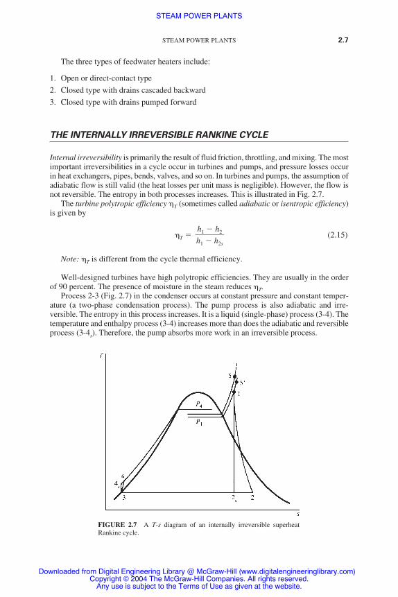
Internal irreversibility is primarily the result of fluid friction, throttling, and mixing. The mostimportant irreversibilities in a cycle occur in turbines and pumps, and pressure losses occurin heat exchangers, pipes, bends, valves, and so on. In turbines and pumps, the assumption ofadiabatic flow is still valid (the heat losses per unit mass is negligible). However, the flow isnot reversible. The entropy in both processes increases. This is illustrated in Fig. 2.7.
The turbine polytropic efficiency �T (sometimes called adiabatic or isentropic efficiency)is given by
�T � (2.15)
Note: �T is different from the cycle thermal efficiency.
Well-designed turbines have high polytropic efficiencies. They are usually in the orderof 90 percent. The presence of moisture in the steam reduces �T.
Process 2-3 (Fig. 2.7) in the condenser occurs at constant pressure and constant temper-ature (a two-phase condensation process). The pump process is also adiabatic and irre-versible. The entropy in this process increases. It is a liquid (single-phase) process (3-4). Thetemperature and enthalpy process (3-4) increases more than does the adiabatic and reversibleprocess (3-4s). Therefore, the pump absorbs more work in an irreversible process.
h1 � h2�h1 � h2s
STEAM POWER PLANTS 2.7
FIGURE 2.7 A T-s diagram of an internally irreversible superheatRankine cycle.
STEAM POWER PLANTS
Downloaded from Digital Engineering Library @ McGraw-Hill (www.digitalengineeringlibrary.com)Copyright © 2004 The McGraw-Hill Companies. All rights reserved.
Any use is subject to the Terms of Use as given at the website.

The pump polytropic efficiency �p (sometimes called adiabatic or isentropic efficiency)is given by
�p � � (2.16)
�p is the reverse of �T.The actual pump work is given by
Wp � ≈ (2.17)
The liquid leaving the pump is at a higher pressure than the turbine inlet (due to frictionthroughout the system). The steam leaving the steam generator at point 5 enters the turbineat point 1. (See Fig. 2.7.) The pressure drop between points 5 and 1 is the result of the com-bined effects of friction and heat losses. Point 5′ represents the frictional effects in the pipeconnecting the steam generator and turbine, including the turbine throttle valve. Heat lossesfrom that pipe reduce the entropy to 1.
OPEN OR DIRECT-CONTACT FEEDWATERHEATERS
The extraction steam is mixed directly with the incoming subcooled feedwater in the openor direct-contact feedwater heater. The mixture becomes saturated water at the extractionsteam pressure.
Figure 2.8 (a, b) shows the flow diagram and corresponding T-s diagram for a Rankinecycle using two feedwater heaters—one a low-pressure feedwater heater and the other ahigh-pressure feedwater heater. (The low-pressure feedwater heater is upstream of the high-pressure feedwater heater.) Normally, modern power plants use one open-type feedwaterheater and between four and seven other heaters.
A typical feedwater heater is shown in Fig. 2.9. The condensate “saturated water” leavesthe condenser at point 5. It is pumped to point 6 to the same pressure as extraction steam atpoint 3. The subcooled water at point 6 and wet steam at point 3 mix in the low-pressurefeedwater heater to produce saturated water at point 7.
The amount m•3 is sufficient to saturate the subcooled water at point 6. If the extraction
steam at point 3 were m• ′3 (where m•3′ � m•
3), the flow at point 7 would be a two-phase mix-ture that would be difficult to pump. The pressure at line 6-7 (constant) cannot be higherthan the extraction steam at point 3. Otherwise, reverse flow of condensate water wouldenter the turbine at point 3.
A second pump is needed to pressurize the saturated water from point 7 to a subcooledcondition at point 8, which is the pressure of extraction steam at point 2. The steam at point10 enters the steam generator at its pressure. A deaerator is usually added to the open-typefeedwater heaters. The mixing process increases the surface area and liberates noncon-densable gases (e.g., N2, O2, and CO2). These gases can be vented to atmosphere. Hence,the arrangement is called deaerating heaters or DA.
The mass balance is as follows:
Mass flow between points 1 and 2 � 1.
Mass flow between points 2 and 9 � m•2.
Mass flow between points 2 and 3 � 1 � m•2.
Mass flow between points 3 and 7 � m•3.
v3 (P4 � P3)���p
h4s � h3��p
(ideal work) ��(actual work)
h4s � h3�h4 � h3
2.8 CHAPTER TWO
STEAM POWER PLANTS
Downloaded from Digital Engineering Library @ McGraw-Hill (www.digitalengineeringlibrary.com)Copyright © 2004 The McGraw-Hill Companies. All rights reserved.
Any use is subject to the Terms of Use as given at the website.

Mass flow between points 3 and 7 � 1 � m•2 � m•
3.
Mass flow between points 7 and 9 � 1 � m•2.
Mass flow between points 9 and 1 � 1.
The energy balances for the high- and low-pressure feedwater heaters, respectively, areas follows:
m•2 (h2 � h9) � (1 � m•
2) (h9 � h8) (2.18)
m•3 (h3 � h7) � (1 � m•
2 � m•3) (h7 � h6) (2.19)
Heat added
qA � (h1 � h10) (2.20)
STEAM POWER PLANTS 2.9
FIGURE 2.8 (a) Schematic flow and (b) T-s diagrams of a nonidealsuperheat Rankine cycle with two open-type feedwater heaters.
STEAM POWER PLANTS
Downloaded from Digital Engineering Library @ McGraw-Hill (www.digitalengineeringlibrary.com)Copyright © 2004 The McGraw-Hill Companies. All rights reserved.
Any use is subject to the Terms of Use as given at the website.

Turbine work
wT � (h1 � h2) � (1 � m•2) (h2 � h3) � (1 � m•
2 � m•3) (h3 � h4) (2.21)
Pump work
|∑wp| � (1 � m•2 � m•
3) (h6 � h5) � (1 � m•2) (h8 � h7)
� (h10 � h9) ≈ (1 � m•2 � m•
3)
� (1 � m•2) � (2.22)
Heat rejected
|qR| � (1 � m•2 � m•
3) (h4 � h5) (2.23)
v9 (P10 � P9)���pJ
v7 (P8 � P7)���pJ
v5 (P6 � P5)���pJ
2.10 CHAPTER TWO
FIGURE 2.9 A typical combination open-type deaerating feedwater heater. (Courtesy Chicago Heater, Inc.)
STEAM POWER PLANTS
Downloaded from Digital Engineering Library @ McGraw-Hill (www.digitalengineeringlibrary.com)Copyright © 2004 The McGraw-Hill Companies. All rights reserved.
Any use is subject to the Terms of Use as given at the website.

Net cycle work
�wnet � wT � |wp| (2.24)
Cycle thermal efficiency
�th � (2.25)
Work ratio
WR � (2.26)
where �p is the pump efficiency and J � 778.16 ft � lbf /Btu.
Note that the turbine work has decreased for the same mass-flow rate because ofreduced turbine mass-flow rate after bleeding. The pump work has also increased.
Note also the decrease in heat added which makes up more than the loss on net work. Thisresults in significant improvement in cycle efficiency. The improvement in efficiencyincreases with the number of feedwater heaters. The maximum number of feedwater heatersused is eight. Any increase beyond eight causes little increase in efficiency and adds compli-cations to the system. The increase in capital cost would not justify the increase in efficiency.
CLOSED-TYPE FEEDWATER HEATER WITHDRAINS CASCADED BACKWARD
This is the most commonly used type of feedwater heaters in power plants. It is a shell-and-tube heat exchanger. The feedwater passes through the tubes. On the shell side, the bledsteam transfers energy to the feedwater as it condenses. Feedwater heaters are very similarto condensers, but they operate at higher pressures.
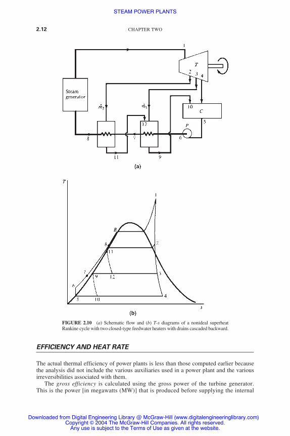
A boiler feedpump is usually placed after the deaerater. Figure 2.10 illustrates the flowdiagram and the corresponding T-s diagram of a nonideal superheat Rankine cycle.
The cycle has two feedwater heaters of this type. Only one pump is needed. The bledsteam condenses in each feedwater heater. Then, it is fed back to the next lower-pressurefeedwater heater (it cascades from higher-pressure to lower-pressure heaters). Wet steamat point 3 is admitted and transfers its energy to high-pressure subcooled water at point 6.
Figure 2.11 illustrates the temperature-length diagram of this heater. The temperature ofthe water at point 7 cannot reach the inlet bled steam temperature at point 3. A differencecalled the terminal temperature difference (TTD, sometimes simply TD) is defined for allclosed feedwater heaters as
TTD � saturation temperature of bled steam � exit water temperature (2.27)
Usually, the TTD is in the order of 2.78°C (5°F).A closed feedwater heater that receives saturated or wet steam can have a drain cooler.
Thus, it is composed of a condensing section and a drain cooler section (Fig. 2.11).Table 2.2 shows the results of example calculations for ideal Rankine cycles. By com-
paring cycles C and B, note the reduction of work but the improvement of �th in cycle Cdue to feedwater heating. In general, comparison between the various cycles shows largeincreases in efficiencies as a result of superheat, reheat, and the use of one feedwater heater.
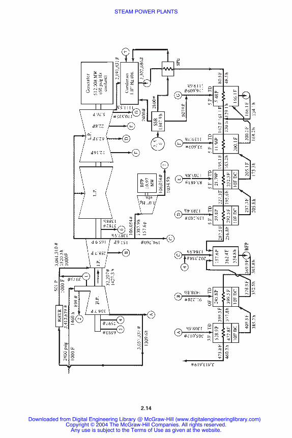
Figure 2.12 shows a flow diagram of an actual 512-MW power plant with superheat,reheat, and seven feedwater heaters.
wnet�wT
�wnet�qA
STEAM POWER PLANTS 2.11
STEAM POWER PLANTS
Downloaded from Digital Engineering Library @ McGraw-Hill (www.digitalengineeringlibrary.com)Copyright © 2004 The McGraw-Hill Companies. All rights reserved.
Any use is subject to the Terms of Use as given at the website.
EFFICIENCY AND HEAT RATE
The actual thermal efficiency of power plants is less than those computed earlier becausethe analysis did not include the various auxiliaries used in a power plant and the variousirreversibilities associated with them.
The gross efficiency is calculated using the gross power of the turbine generator.This is the power [in megawatts (MW)] that is produced before supplying the internal
2.12 CHAPTER TWO
FIGURE 2.10 (a) Schematic flow and (b) T-s diagrams of a nonideal superheatRankine cycle with two closed-type feedwater heaters with drains cascaded backward.
STEAM POWER PLANTS
Downloaded from Digital Engineering Library @ McGraw-Hill (www.digitalengineeringlibrary.com)Copyright © 2004 The McGraw-Hill Companies. All rights reserved.
Any use is subject to the Terms of Use as given at the website.

equipment of the power plant (e.g., pumps, compressors, fuel-handling equipment,computers, etc.).
The net efficiency is calculated based on the net power of the plant (the gross powerminus the power needed for the internal equipment of the plant).
SUPERCRITICAL PLANTS
Figure 2.13 illustrates the T-s diagram of an ideal supercritical, double-reheat 3500psi/1000°F/1025°F/1050°F power plant. They usually have higher thermal efficienciesthan subcritical plants. Their capital cost is higher than subcritical plants due to the need forsuitable material and sealing devices that can withstand high temperature and pressure forlong periods of time.
STEAM POWER PLANTS 2.13
FIGURE 2.11 Temperature-enthalpy diagrams of (a, b) low-pressure and (c) high-pressure feedwaterheaters of Fig. 2.15. C � condenser, DC � drain cooler, DS � desuperheater, TTD � terminal temperaturedifference.
TABLE 2.2 Results of Example Calculations for Ideal Rankine Cycles*
Cycle Particulars �wnet qA �% |qR| WR
A No superheat; no fwh† 413.72 1120.19 36.93 706.49 0.9928B Superheat; no fwh 579.11 1432.69 40.42 853.58 0.9949C Superheat; one open fwh 519.3 1203.95 43.13 685.25 0.9939D Superheat; one closed fwh;
drains cascaded; DC† 520.31 1212.04 42.93 691.68 0.9943E Superheat; one closed fwh;
drains pumped; DC 529.85 1245.63 42.54 715.73 0.9945F Superheat; one closed fwh;
drains pumped; no DC 520.59 1210.48 43.01 689.95 0.9943G Superheat; reheat; one open
fwh 641.59 1447.44 44.33 805.83 0.9951H Superheat; reheat; two
closed fwh; drains cascaded 609.83 1351.0 45.14 727.62 0.9952I Supercritical; double reheat;
no fwh; 3500/1000/1025/1050 861.95 1831.92 47.05 969.97 0.9880
*All values in Btu/lbm; all examples, except for cycle A (which is saturated), and cycle I, are at 1000 psia/1000°F.All are at 1 psia condenser pressure.
†DC � drain cooler, fwh � feedwater heater.
STEAM POWER PLANTS
Downloaded from Digital Engineering Library @ McGraw-Hill (www.digitalengineeringlibrary.com)Copyright © 2004 The McGraw-Hill Companies. All rights reserved.
Any use is subject to the Terms of Use as given at the website.
2.14
STEAM POWER PLANTS
Downloaded from Digital Engineering Library @ McGraw-Hill (www.digitalengineeringlibrary.com)Copyright © 2004 The McGraw-Hill Companies. All rights reserved.
Any use is subject to the Terms of Use as given at the website.
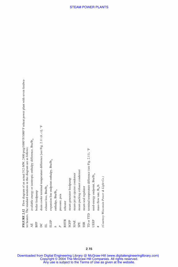
FIG
UR
E 2
.12
Flow
dia
gram
of
an a
ctua
l 512
-MW
, 240
0 ps
ig/1
000°
F/10
00°F
reh
eat p
ower
pla
nt w
ith s
even
fee
dwa-
ter
heat
ers.
The
sta
ndar
d no
tatio
ns in
this
dia
gram
are
as
follo
ws:
AE
avai
labl
e en
ergy
or
isen
trop
ic e
ntha
lpy
diff
eren
ce, B
tu/lb
m
BFP
boile
r fe
edpu
mp
DC
drai
n co
oler
term
inal
tem
pera
ture
dif
fere
nce
[see
Fig
. 2.1
1 (b
, c)]
, °F
EL
exha
ust l
oss,
Btu
/lbm
EL
EP
expa
nsio
n lin
e en
dpoi
nt e
ntha
lpy,
Btu
/lbm
hen
thal
py, B
tu/lb
m
Ppr
essu
re, p
sia
RH
TR
rehe
ater
SGFP
stea
m g
ener
ator
fee
dpum
p
SJA
Est
eam
-jet
air
eje
ctor
con
dens
er
SPE
stea
m p
acki
ng e
xhau
st c
onde
nser
SSR
stea
m s
eal r
egul
ator
TD
or
TT
Dte
rmin
al te
mpe
ratu
re d
iffe
renc
e (s
ee F
ig. 2
.11)
, °F
UE
EP
used
-ene
rgy
endp
oint
, Btu
/lbm
#m
ass-
flow
rat
e, lb
m/h
(Cou
rtes
y W
isco
nsin
Pow
er &
Lig
ht C
o.)
2.15
STEAM POWER PLANTS
Downloaded from Digital Engineering Library @ McGraw-Hill (www.digitalengineeringlibrary.com)Copyright © 2004 The McGraw-Hill Companies. All rights reserved.
Any use is subject to the Terms of Use as given at the website.

COGENERATION
Cogeneration is the simultaneous generation of electricity and steam (or heat) in a powerplant. Cogeneration is recommended for industries and municipalities because it can pro-duce electricity more cheaply and/or more conveniently than a utility. Also, it provides thetotal energy needs (heat and electricity) for the industry or municipality.
Cogeneration is beneficial if it saves energy when compared with separate generationof electricity and steam (or heat). The cogeneration plant efficiency �co is given by
�co � (2.28)
where E � electric energy generated�Hs � heat energy, or heat energy in process steam
� (enthalpy of steam entering the process) � (enthalpy of process condensatereturning to plant)
QA � heat added to plant (in coal, nuclear fuel, etc.)
For separate generation of electricity and steam, the heat added per unit of total energyoutput is
� (2.29)(1 � e)��h
e��e
E � �Hs�QA
2.16 CHAPTER TWO
FIGURE 2.13 T-s diagram of an ideal supercritical, double-reheat3500/1000/1025/1050 steam cycle.
STEAM POWER PLANTS
Downloaded from Digital Engineering Library @ McGraw-Hill (www.digitalengineeringlibrary.com)Copyright © 2004 The McGraw-Hill Companies. All rights reserved.
Any use is subject to the Terms of Use as given at the website.

where e � electrical fraction of total energy output � [E/ (E��Hs) ]�e � electric plant efficiency�h � steam (or heat) generator efficiency
The combined efficiency �c for separate generation is therefore given by
�c � (2.30)
Cogeneration is beneficial if the efficiency of the cogeneration plant [Eq. (2.28)] isgreater than that of separate generation [Eq. (2.30)].
Types of Cogeneration
The two main categories of cogeneration are (1) the topping cycle and (2) the bottomingcycle.
The Topping Cycle. In this cycle, the primary heat source is used to generate high-enthalpy steam and electricity. Depending on process requirements, process steam at lowenthalpy is taken from any of the following:
● Extracted from the turbine at an intermediate stage (like feedwater heating).● Taken from the turbine exhaust. The turbine in this case is called a back-pressure turbine.
Process steam requirements vary widely, between 0.5 and 40 bar.
The Bottoming Cycle. In this cycle, the primary heat (high enthalpy) is used directly forprocess requirements [e.g., for a high-temperature cement kiln (furnace)]. The low-enthalpy waste heat is then used to generate electricity at low efficiency.
This cycle has lower combined efficiency than the topping cycle. Thus, it is not verycommon. Only the topping cycle can provide true savings in primary energy.
Arrangements of Cogeneration Plants
The various arrangements for cogeneration in a topping cycle are as follows:
● Steam-electric power plant with a back-pressure turbine.● Steam-electric power plant with steam extraction from a condensing turbine (Fig. 2.14).● Gas turbine power plant with a heat recovery boiler (using the gas turbine exhaust to gen-
erate steam).● Combined steam-gas-turbine cycle power plant. The steam turbine is either of the back-
pressure type or of the extraction-condensing type.
Economics of Cogeneration
Cogeneration is recommended if the cost of electricity is less than the utility. If a utility isnot available, cogeneration becomes necessary, regardless of economics.
The two types of power plant costs are (1) capital costs and (2) production costs. Capitalcosts are given in total dollars or as unit capital costs in dollars per kilowatt net. Capital
1���(e/�e) � [(1 � e)/�h]
STEAM POWER PLANTS 2.17
STEAM POWER PLANTS
Downloaded from Digital Engineering Library @ McGraw-Hill (www.digitalengineeringlibrary.com)Copyright © 2004 The McGraw-Hill Companies. All rights reserved.
Any use is subject to the Terms of Use as given at the website.

costs determine if a plant is good enough to obtain financing. Thus, it is able to pay the fixedcharges against capital costs.
Production costs are calculated annually, and they are given in mills per kilowatt hour(a mill is U.S.$0.001). Production costs are the real measure of the cost of power generated.They are composed of the following:
● Fixed charges against the capital costs● Fuel costs● Operation and maintenance costs
All the costs are in mills per kilowatt hour. They are given by
Production costs � (2.31)
where the period is usually taken as one year.The plant operating factor (POF) is defined for all plants as
POF � (2.32)total net energy generated by plant during a period of time������rated net energy capacity of plant during the same period
total (a � b � c) $ spent per period 103
�����KWh (net) generated during the same period
2.18 CHAPTER TWO
FIGURE 2.14 Schematic of basic cogeneration plant with extraction-condensing turbine.
STEAM POWER PLANTS
Downloaded from Digital Engineering Library @ McGraw-Hill (www.digitalengineeringlibrary.com)Copyright © 2004 The McGraw-Hill Companies. All rights reserved.
Any use is subject to the Terms of Use as given at the website.

STEAM TURBINES ANDAUXILIARIES
In a steam turbine, high-enthalpy (high pressure and temperature) steam is expanded in thenozzles (stationary blades) where the kinetic energy is increased at the expense of pressureenergy (increase in velocity due to decrease in pressure). The kinetic energy (high veloc-ity) is converted into mechanical energy (rotation of a shaft � increase of torque or speed)by impulse and reaction principles. The impulse principle consists of changing the momen-tum (mV) of the flow, which is directed to the moving blades by the stationary blades. Thejet’s impulse force pushes the moving blades forward. The reaction principle consists of areaction force on the moving blades due to acceleration of the flow as a result of decreas-ing cross-sectional area.
Figure 3.1 illustrates a turbine with impulse blading. It has one velocity-compoundedstage (the velocity is absorbed in stages) and four pressure-compounded stages. The veloc-ity is reduced in two steps through the first two rows of moving blades. In the movingblades, velocity decreases while the pressure remains constant.
Figure 3.2 illustrates a reaction turbine. The reaction stages are preceded by an ini-tial velocity-compounded impulse stage where a large pressure drop occurs. This resultsin a shorter, less expensive turbine. Figure 3.3 illustrates the arrangement of compo-nents in a steam power plant.
TURBINE TYPES
Steam turbines up to between 40 and 60 MW rating are usually single-cylinder machines.Larger units use multiple cylinders to extract the energy from the steam.
Single-Cylinder Turbines
The two types of steam turbines are condensing and back-pressure (noncondensing).Figure 3.4 illustrates these types and some of their subclassifications. Back-pressure tur-bines exhaust the steam at the pressure required by the process. Automatic extraction turbines allow part of the steam to be withdrawn at an intermediate stage (or stages)while the remainder of the steam is exhausted to a condenser. These turbines requirespecial governors and valves to maintain constant pressure of the extraction steam whilethe turbine load and extraction demand are varying. Uncontrolled extraction turbines areused to supply steam to feedwater heaters, since the pressure at the extraction pointsvaries with the turbine load.
CHAPTER 3
3.1
Downloaded from Digital Engineering Library @ McGraw-Hill (www.digitalengineeringlibrary.com)Copyright © 2004 The McGraw-Hill Companies. All rights reserved.
Any use is subject to the Terms of Use as given at the website.
Source: POWER GENERATION HANDBOOK

Many moderate-pressure plants have added high-pressure noncondensing turbines toincrease capacity and improve efficiency. High-pressure boilers are added to supplysteam to the noncondensing turbines, which are designed to supply the steam to the orig-inal turbines. These high-pressure turbines are called superposed, or topping, units.Mixed-pressure turbines are designed to admit steam at low pressure and expand it to acondenser. These units are used mainly in cogeneration plants.
3.2 CHAPTER THREE
FIGURE 3.1 Turbine with impulse blading. Velocity compounding is accomplished in the firsttwo stages by two rows of moving blades between which is placed a row of stationary blades thatreverses the direction of steam flow as it passes from the first to the second row of moving blades.Other ways of accomplishing velocity compounding involve redirecting the steam jets so that theystrike the same row of blades several times with progressively decreasing velocity.
STEAM TURBINES AND AUXILIARIES
Downloaded from Digital Engineering Library @ McGraw-Hill (www.digitalengineeringlibrary.com)Copyright © 2004 The McGraw-Hill Companies. All rights reserved.
Any use is subject to the Terms of Use as given at the website.

STEAM TURBINES AND AUXILIARIES 3.3
FIGURE 3.2 Reaction turbine with one velocity–compounded impulse stage. The firststage of this turbine is similar to the first velocity-compounded stage of Fig. 3.1. However,in the reaction blading of this turbine, both pressure and velocity decrease as the steamflows through the blades. The graph at the bottom shows the changes in pressure and velocitythrough the various stages.
STEAM TURBINES AND AUXILIARIES
Downloaded from Digital Engineering Library @ McGraw-Hill (www.digitalengineeringlibrary.com)Copyright © 2004 The McGraw-Hill Companies. All rights reserved.
Any use is subject to the Terms of Use as given at the website.

3.4 CHAPTER THREE
FIGURE 3.4 Single-cylinder turbine types. Typical types of single-cylinder tur-bines are illustrated. As shown, condensing turbines, as compared to back-pressureturbines, must increase more in size toward the exhaust end to handle the largervolume of low-pressure steam.
FIGURE 3.3 Simple power plant cycle. This diagram shows that the working fluid, steam and water, travelsa closed loop in the typical power plant cycle.
STEAM TURBINES AND AUXILIARIES
Downloaded from Digital Engineering Library @ McGraw-Hill (www.digitalengineeringlibrary.com)Copyright © 2004 The McGraw-Hill Companies. All rights reserved.
Any use is subject to the Terms of Use as given at the website.

Compound Turbines
Compound turbines have more than one cylinder: a high-pressure and a low-pressureturbine. The low-pressure cylinder is usually of the double-flow type to handle largevolumes of low-pressure steam (due to limitations on the length of the blades). Largeplants may have an intermediate pressure cylinder and up to four low-pressure cylin-ders. The cylinders can be mounted along a single shaft (tandem-compound), or in par-allel groups with two or more shafts (cross-compound). Reheating is usually donebetween the high- and intermediate-pressure turbines. Figure 3.5 illustrates some ofthese arrangements.
STEAM TURBINES AND AUXILIARIES 3.5
FIGURE 3.5 Some arrangements of compound turbines. Whilemany arrangements are used, these diagrams illustrate some of themore common ones.
STEAM TURBINES AND AUXILIARIES
Downloaded from Digital Engineering Library @ McGraw-Hill (www.digitalengineeringlibrary.com)Copyright © 2004 The McGraw-Hill Companies. All rights reserved.
Any use is subject to the Terms of Use as given at the website.

TURBINE CONTROL SYSTEMS
All steam turbines have at least two independent governors that control the flow of steam.The first shuts off the steam supply if the turbine speed exceeds a predetermined maximum.It is often called an emergency trip. The second, or main, governor throttles the flow ofsteam to maintain constant speed (in units not synchronized to a grid) or to vary the load(in units synchronized to a grid). The governors of extraction, mixed-pressure, and back-pressure turbines control the steam flow while the speed and pressures are varying. Thesegovernors are usually extremely complex.
Speed Governors
Speed governor systems consist of the following:
● Speed-sensitive element● Linkage or force-amplifying mechanism that transmits motion from the governor to the
steam control valves● Steam control valves (governing valves)
Figure 3.6 illustrates a centrifugal, or flyball, governor. The weights, mounted on oppositesides of the spindle and revolving with it, move outward by centrifugal force against aspring when the turbine speed increases. This action actuates the steam admission valve byone of the following:
● Mechanical linkage● Operation of the pilot valve of a hydraulic system, which admits or releases oil to oppo-
site sides of a power piston, or to one side of a spring-loaded piston (movement of thepower piston opens or closes the steam valves)
Moderate and large units are equipped with a double-relay hydraulic system to boost theforce of a centrifugal governor and to reduce the response time of the system. Interceptvalves are installed upstream of the intermediate-pressure turbine. They are closed by thegovernor system upon a load rejection (opening of the circuit breaker as a result of a dis-turbance in transmission) or a sudden load reduction. The intercept valves interrupt the flowof steam from the high-pressure turbine, the reheater, and the piping to the intermediate-pressure turbine, thus preventing overspeeding of the turbine.
Pressure Governors
The governors of back-pressure and automatic extraction turbines are designed to maintainconstant extraction or exhaust pressure, regardless of the load. The signal from a pressuretransducer is communicated to the steam extraction control valves and the speed governor,which controls the steam flow to the turbine. On automatic extraction turbines, the governorcoordinates the signals from the pressure and speed transducer to maintain constant speed.
LUBRICATION REQUIREMENTS
The parts requiring lubrication include journal and thrust bearings, hydraulic control sys-tem, oil shaft seals, gears, flexible couplings, and turning gears.1
3.6 CHAPTER THREE
STEAM TURBINES AND AUXILIARIES
Downloaded from Digital Engineering Library @ McGraw-Hill (www.digitalengineeringlibrary.com)Copyright © 2004 The McGraw-Hill Companies. All rights reserved.
Any use is subject to the Terms of Use as given at the website.

JOURNAL BEARINGS
Hydrodynamic journal bearings are used to support steam turbines and generators. Due to theextremely tight clearances between the moving blades and the casing, these bearings must beaccurately aligned and must operate without any appreciable wear to maintain the shaft in itsoriginal position and avoid damage to the blades. The bearings are usually of the horizontallysplit shell and they are lined with tin-base babbitt (soft metal).
The passages and grooves inside the turbine bearings are designed to allow more oil thanrequired for lubrication only. The additional oil is required to remove frictional heat and heatconducted to the bearings along the shaft from the hot sections of the turbine. The oil flowmust maintain the bearings at proper operating temperature. In most applications, the oilleaving the bearings is around 160°F (71°C). An oil-lift system (jacking oil) is needed formost large turbines to lift the turbine and reduce the possibility of damage during start-upand shutdown. The jacking oil system is also needed to reduce the starting load on the turn-ing gear. A positive-displacement pump delivers high-pressure oil to openings in the bottom
STEAM TURBINES AND AUXILIARIES 3.7
FIGURE 3.6 Mechanical speed governor. A simple arrangement such as this usinga flyball governor is suitable for many small turbines.
STEAM TURBINES AND AUXILIARIES
Downloaded from Digital Engineering Library @ McGraw-Hill (www.digitalengineeringlibrary.com)Copyright © 2004 The McGraw-Hill Companies. All rights reserved.
Any use is subject to the Terms of Use as given at the website.

of the bearings. The high-pressure oil lifts the shaft and floats it on an oil film until the shaftspeed is high enough to create a hydrodynamic film between the shaft and the babbitt.
A phenomenon known as oil whip or oil whirl occurs in relatively lightly loaded, high-speed journal bearings. The center of the journal (portion of the shaft inside the bearing)assumes an eccentric position in the bearing. This position is determined by load, speed, andoil viscosity. Since the stable position is near the center of the bearing, the journal center startsto move in a circular path about the stable position. The vibrations created by this motion havea frequency of less than one-half the shaft speed. Pressure-pad (Fig. 3.7), three-lobe (Fig. 3.8),
3.8 CHAPTER THREE
DAM
LOAD-SUPPORTING
OIL FILM
FIGURE 3.7 Pressure bearing. The wide groove in the upper half ends in a sharp dam at the point indi-cated. As shown in the insert, this causes a downward pressure that forces the journal into a more eccentricposition that is more resistant to oil whirl.
FIGURE 3.9 Tilting-pad antiwhip bearing. As inthe three-lobe bearing, the multiple oil films formedtend to keep the journal in a stable position.
FIGURE 3.8 Three-lobe bearing. The shape ofthe bearing is formed by three arcs of radius some-what greater than the radius of the journal. Thishas the effect of creating a separate hydrodynamicfilm in each lobe, and the pressures in these filmstend to keep the journal in a stable position.
STEAM TURBINES AND AUXILIARIES
Downloaded from Digital Engineering Library @ McGraw-Hill (www.digitalengineeringlibrary.com)Copyright © 2004 The McGraw-Hill Companies. All rights reserved.
Any use is subject to the Terms of Use as given at the website.
and tilting-pad (Fig. 3.9) bearings are designed to suppress oil whip. The pressure-pad bearingsuppresses oil whip by having a wide groove that ends in a sharp dam, which causes down-ward pressure that forces the journal into a more eccentric position to resist oil whirl. The othertypes rely on the formation of multiple oil films to preload the journal and prevent oil whip.
THRUST BEARINGS
Axial thrust is caused by the difference in pressure across each row of moving blades.Rotors that are stepped up in diameter also create axial thrust. This thrust is counteractedby axial thrust bearings, which maintain the rotor in correct axial position.
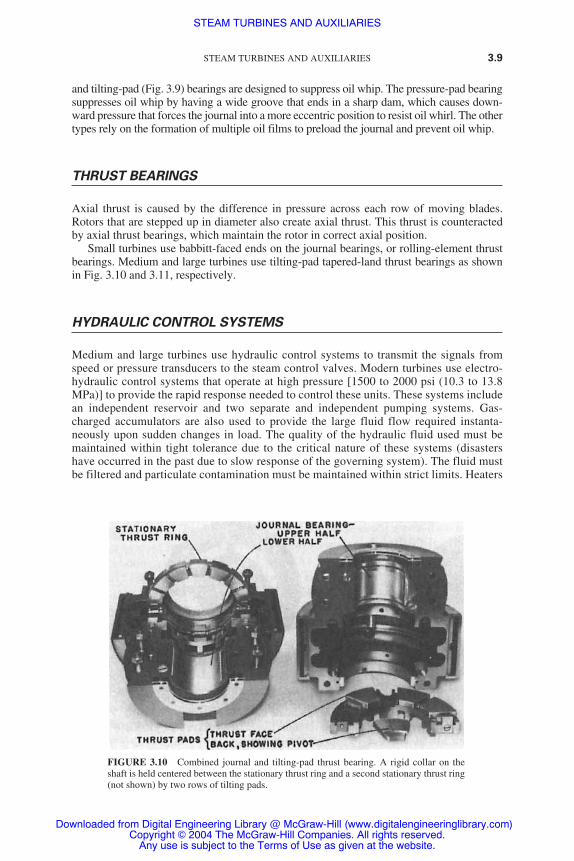
Small turbines use babbitt-faced ends on the journal bearings, or rolling-element thrustbearings. Medium and large turbines use tilting-pad tapered-land thrust bearings as shownin Fig. 3.10 and 3.11, respectively.
HYDRAULIC CONTROL SYSTEMS
Medium and large turbines use hydraulic control systems to transmit the signals fromspeed or pressure transducers to the steam control valves. Modern turbines use electro-hydraulic control systems that operate at high pressure [1500 to 2000 psi (10.3 to 13.8MPa)] to provide the rapid response needed to control these units. These systems includean independent reservoir and two separate and independent pumping systems. Gas-charged accumulators are also used to provide the large fluid flow required instanta-neously upon sudden changes in load. The quality of the hydraulic fluid used must bemaintained within tight tolerance due to the critical nature of these systems (disastershave occurred in the past due to slow response of the governing system). The fluid mustbe filtered and particulate contamination must be maintained within strict limits. Heaters
STEAM TURBINES AND AUXILIARIES 3.9
FIGURE 3.10 Combined journal and tilting-pad thrust bearing. A rigid collar on theshaft is held centered between the stationary thrust ring and a second stationary thrust ring(not shown) by two rows of tilting pads.
STEAM TURBINES AND AUXILIARIES
Downloaded from Digital Engineering Library @ McGraw-Hill (www.digitalengineeringlibrary.com)Copyright © 2004 The McGraw-Hill Companies. All rights reserved.
Any use is subject to the Terms of Use as given at the website.

and coolers are used to maintain the temperature and, thus, viscosity in a narrow range.Fire-retardant fluids (FRFs) are used in these systems to prevent a fire from occurringupon a leak, which would spray hydraulic fluid on hot-steam piping and valves due tohigh pressure.
GEAR DRIVES
Efficient turbine speed is sometimes different from the operating speed of the equipmentbeing driven. In these applications, the turbine is connected to the driven equipment byreduction gears. A separate oil-tight casing is usually used to enclose the gears that are con-nected to the turbine and driven equipment through flexible couplings. The oil circulationsystem for the gears may be entirely separate from the turbine system or may be suppliedfrom it. A separate pump is used in the latter case.
3.10 CHAPTER THREE
FIGURE 3.11 Tapered-land thrust bearing and plain journal bearing. The thrust bearingconsists of a collar on the shaft, two stationary bearing rings, one on each side of the collar.The babbitted thrust faces of the bearing rings are cut into sectors by radial grooves. About80 percent of each sector is beveled to the leading radial groove, to permit the formation ofwedge oil films. The unbeveled portions of the sectors absorb the thrust load when speed istoo low to form hydrodynamic films.
STEAM TURBINES AND AUXILIARIES
Downloaded from Digital Engineering Library @ McGraw-Hill (www.digitalengineeringlibrary.com)Copyright © 2004 The McGraw-Hill Companies. All rights reserved.
Any use is subject to the Terms of Use as given at the website.

TURNING GEAR
During start-up and shutdown, the rotor should be rotated slowly to avoid uneven heatingor cooling, which could distort or bow the shaft. A barring mechanism or a turning gear isused for this purpose. The turning gear consists of a motor that is temporarily coupled tothe turbine by reduction gears. The turning gear speed is usually below 100 rpm. A sepa-rate auxiliary oil pump is used to provide adequate flow to the bearings during the low-speed operation. The service water flow in the oil coolers is maximized to increase theviscosity of the oil and assist in maintaining the oil film in the bearings. The jacking oil sys-tem is operated while the turning gear is operating.
FACTORS AFFECTING LUBRICATION
Circulation and Heating in the Presence of Air
Heat is generated within the bearings by friction and heat conduction along the shaft. Oil isbroken into droplets while it is flowing. This allows greater exposure to air. During operation,oxidation (combination of the oil molecules with oxygen) occurs. Fine metal particles result-ing from wear or contamination and water act as a catalyst (enhance the rate) to oxidation.The viscosity of oil increases with oxidation. Insoluble oxidation products such as varnish andsludge may settle out on governor components, in bearings, heat exchangers, and strainers.Their accumulation will interfere with governor operation and oil flow to the bearings.
Contamination
Water is the most prevalent contamination in turbine lubrication systems. Three commonsources of water include:
1. Leaking turbine and pump seals
2. Condensation of humid air
3. Water leaks in heat exchangers
Emulsion will form when the oil is mixed with water. The emulsion will separatequickly when the oil is new and clean. The water will settle in the reservoir where it can beremoved by purification equipment. Oxidation or contamination of the oil will increase thetendency of the oil to emulsify. Emulsions can mix with insoluble oxidation products anddirt to form sludges. Water can combine with air to form red and black rust, which is sim-ilar in appearance to pipe scale. Particles of rust have the following effects:
● Act as catalysts that increase the rate of oil oxidation.● Scratch the journals and cause excessive wear.● Get entrained into the small clearances of the governing system. This will cause sluggish
operation and, in extreme cases, disasters (due to slow operation of the governing valve).
Oil can become contaminated by air to form “bubbly” oil. This oil is compressible andcan cause sponginess in hydraulic controls. It may reduce the load-carrying capability ofoil films. Entrained air increases the rate of oxidation. An excessive amount of air can gen-erate foaming in the reservoir or bearing housings.
STEAM TURBINES AND AUXILIARIES 3.11
STEAM TURBINES AND AUXILIARIES
Downloaded from Digital Engineering Library @ McGraw-Hill (www.digitalengineeringlibrary.com)Copyright © 2004 The McGraw-Hill Companies. All rights reserved.
Any use is subject to the Terms of Use as given at the website.
LUBRICATING OIL CHARACTERISTICS
The steam turbine oil should have (1) the proper viscosity at operating temperatures to pro-vide the lubricating films, and (2) adequate load-carrying ability to reduce wear.
Viscosity
The journal and thrust bearings of steam turbines require lubrication. Oils having higherviscosity provide a greater margin of safety in the bearings. However, its friction losses arehigh. In high-speed turbines, the heat generation becomes significant. Most oils used in thisservice have International Organization for Standardization (ISO) viscosity grade 32 [28.8to 35.2 centistokes (cSt) at 40°C]. Higher viscosity is used in some applications, ISO vis-cosity grade 46 (41.4 to 50.6 cSt at 40°C).
Higher-viscosity oils are used for geared turbines to provide adequate lubrication for thegears. Most of these systems use oils of ISO viscosity grade 68 (61.2 to 74.8 cSt at 40°C).Some geared turbines cool the oil in a heat exchanger before delivering it to the gears. Theincrease in viscosity provides better protection for the gears.
Load-Carrying Ability
Steam turbines normally use mineral oils. Boundary lubrication conditions occur in tur-bines not equipped with lifts. Wear will occur under these conditions unless lubricants withenhanced film strength are used. The higher viscosity of cool oil provides the increase inload-carrying ability of the oil films needed during start-up. Additives are also frequentlyused in turbine oil to improve the film strength.
Oxidation Stability
The ability to resist oxidation is the most important characteristic of turbine oils. This prop-erty is important from the standpoint of retention of viscosity (resistance to the formationof sludges, deposits, and corrosive oil oxyacids) and retention of the ability to separatewater, resist foam, and release entrained air.
Protection Against Rusting
Rust inhibitors are required from turbine oils to improve their ability to protect against rust-ing of ferrous surfaces. These inhibitors “plate out” on metal surfaces to resist the penetra-tion of water.
Water-Separating Ability
New mineral oils usually resist emulsification when there is water ingress. Any emulsionformed breaks quickly. Some additives such as rust inhibitors increase the tendency of anoil to emulsify. Thus, additives should be selected carefully to ensure that the oil has goodwater-separating ability.
3.12 CHAPTER THREE
STEAM TURBINES AND AUXILIARIES
Downloaded from Digital Engineering Library @ McGraw-Hill (www.digitalengineeringlibrary.com)Copyright © 2004 The McGraw-Hill Companies. All rights reserved.
Any use is subject to the Terms of Use as given at the website.
Foam Resistance
Turbine oils usually contain defoamants to reduce the foaming tendency. Since oxidationincreases the tendency to foam, good oxidation stability is essential to maintain good resis-tance to foaming.
Entrained-Air Release
Entrained air can cause sponginess and delayed or erratic response. Some additives areknown to degrade the ability of the oil to release entrained air. Thus, the additives selectedfor turbine oil should not reduce its ability to release air.
Fire Resistance
Fire-resistant fluids (FRFs) are normally used in electrohydraulic governor control systemsdue to high pressures (up to 3000 psi). Phosphate esters or blends of phosphate esters andchlorinated hydrocarbons are normally used. These systems are extremely sensitive to thepresence of solid contaminants. Considerable attention should be paid to the filtration ofthe oil.
REFERENCE
1. Wills, G., Lubrication Fundamentals, Marcel Dekker, New York, 1980.
STEAM TURBINES AND AUXILIARIES 3.13
STEAM TURBINES AND AUXILIARIES
Downloaded from Digital Engineering Library @ McGraw-Hill (www.digitalengineeringlibrary.com)Copyright © 2004 The McGraw-Hill Companies. All rights reserved.
Any use is subject to the Terms of Use as given at the website.

STEAM TURBINES AND AUXILIARIES
Downloaded from Digital Engineering Library @ McGraw-Hill (www.digitalengineeringlibrary.com)Copyright © 2004 The McGraw-Hill Companies. All rights reserved.
Any use is subject to the Terms of Use as given at the website.
TURBINE GOVERNINGSYSTEMS
The four main functions of the governing system1 are as follows:
1. To limit the speed rise to an acceptable limit upon a load rejection (when the unit is sud-denly disconnected from the load)
2. To control the power that is generated by controlling the position of the steam govern-ing valve (or fuel valve in gas turbines)
3. To control the speed of the turbogenerator during initial run-up and synchronization
4. To match the power that is generated to the power that is required by the load byresponding to frequency changes [only when the generator is operating in islandingmode (i.e., alone), independently from the grid]
The first function is critical to the safety and availability of the plant. If the breaker con-necting the generator to the grid opens during normal operation, the shaft speed willincrease significantly due to the elimination of the countertorque produced by the genera-tor. The steam flow must be reduced instantly to limit the speed rise. Most machines havea separate overspeed trip to ensure safety of the plant and personnel upon failure of the gov-erning system. It consists of overspeed bolts that protrude out of the shaft. They trip a leverwhen their overspeed setpoint is reached. This results in depressurization of the hydraulicoil of the governing system leading to closure of the governing valve. Another trip on highacceleration is also included in some plants. Upon a load rejection (opening of the breakerconnecting the generator to the grid), acceleration sensors trip the steam valves on highacceleration.
Following a load rejection, the governor must maintain the unit at the running speed.This is done for two reasons:
1. To ensure continuity of the unit power supplies from its own generator through the unitservice transformer (UST).
2. Providing resynchronization capability to the unit upon termination of the fault.
Note: Many problems occurring on the grid are short-lived (lasting less than 1 hour).
The initial transient overspeed (normally limited to less than 8 percent) that occurs aftera load rejection is caused by the following two reasons:
1. The response time of the governing valve (GV) or the emergency stop valve (ESV) to close
2. The stored energy of the steam within the turbines and their associated pipework
CHAPTER 4
4.1
Downloaded from Digital Engineering Library @ McGraw-Hill (www.digitalengineeringlibrary.com)Copyright © 2004 The McGraw-Hill Companies. All rights reserved.
Any use is subject to the Terms of Use as given at the website.
Source: POWER GENERATION HANDBOOK

Figure 4.1 illustrates a typical electrical governing system used in a plant having multi-ple steam turbines. It includes at least one closed-loop control system. The main feedbackis the speed of the turbine shaft. A triplicated circuit using magnetic pickup sensors mea-sures the shaft speed at a toothed wheel located at the high-pressure (HP) end of the shaft.A modular electronic system processes the signal. The electronic system is often located ina cubicle that is remote from the turbine. The output signal from the electronic system isdirected to each steam valve on the turbines.
The processing varies with each application. However, it generally includes the following:
● Speed versus load characteristic of the turbine generator when the machine is synchro-nized
● Predetermined relationship between the governing valve position and the intercept valveposition
● Features that limit the maximum speed of the turbogenerator● Features that limit the power output● Features that allow testing of the system
Each steam valve has a relay that converts the low-power electrical signal generated bythe processing equipment into movement of the valve stem. Several stages of hydraulicamplification are used due to the substantial mechanical forces [150 kilonewtons (kN)] andshort stroking time [�200 milliseconds (ms) upon a load rejection]. The governing system
4.2 CHAPTER FOUR
FIGURE 4.1 Electrical governing system applied to a wet-steam turbine.
TURBINE GOVERNING SYSTEMS
Downloaded from Digital Engineering Library @ McGraw-Hill (www.digitalengineeringlibrary.com)Copyright © 2004 The McGraw-Hill Companies. All rights reserved.
Any use is subject to the Terms of Use as given at the website.

must be able to provide fine control over load (or speed when the machine is not synchro-nized). A typical dead band of modern governing systems is less than ±36 millihertz (mHz).Its sensitivity in positioning the valve is within 0.2 percent of the required position.Hydraulic equipment having high precision and fine clearances are used to achieve highresolution and amplification of small electric signals.
Earlier mechanical/hydraulic governing systems shared the lubricating oil supply withthe turbine. However, modern governing systems use a separate high-quality fluid toimprove the reliability and accuracy of the system. Modern governing systems also have amuch higher hydraulic pressure in their actuators than earlier governing systems (1500 psiversus 200 psi). This increase in the hydraulic pressure was done to reduce the size of theactuator and the response time of the valve. However, the high hydraulic pressure createda fire hazard in the plant. Any small leak from the high-pressure hydraulic system wouldgenerate an oil mist that settles on hot turbine bearings and pipes. These oil leaks can easilygenerate a fire in the plant. Modern governing systems use a special oil called fire-retardantfluid (FRF). This fluid is commonly known as phosphate ester. It does not ignite when itsettles on hot bearings and pipes.
GOVERNOR CHARACTERISTICS
All electrical systems experience faults. Safety is maintained in these situations by protec-tive equipment that opens circuit breakers to isolate the fault. The governing system of aturbine generator must be able to handle a full-load rejection safely and provide appropri-ate contributions to the regulation of system frequency. The relationship between the gen-erated load of a unit and speed is the main characteristic of a governing system. Figure 4.2illustrates the frequency regulation characteristic, also known as the speed-droop charac-teristic, of the governor.
The steady-state overall frequency regulation is defined as
� 100% (4.1)
where NR � rated speedNPR � speed at full-loadN0 � speed at no load
This characteristic allows a machine to share load with other machines and permit theoperator to adjust the load generated by the machine. Figure 4.3 illustrates how varia-tions of the speed setpoint affect the generated load. If the machine is not synchronizedand the no-load speed setpoint is raised from a1 to a3, the frequency will increase froma1 to a3. However, if the machine is synchronized to a grid operating at constant fre-quency a1, an increase in no-load speed setpoint from a1 to a2 and then a3 will increasethe load to b2 and then b3. The linear characteristic shown in Figure 4.3 is for an idealcase. In reality, the characteristic may be nonlinear. The no-load speed setpoint isadjusted between a1 at no-load and a3 at full-load. This range of operation is normallybetween 4 and 6 percent.
Figure 4.3 illustrates also the phenomenon of overwound speed setpoint. If the operatorhas adjusted the speed setpoint to give characteristic a3b3 (the unit is running at full-load ata frequency f ), a decrease in the grid frequency by an amount �f will give an indication thatthe load will increase to c3. However, since the load is determined by the turbine, which isalready operating at full power, the load will not increase beyond b3. The speed setpoint is
N0 � NPR��NR
TURBINE GOVERNING SYSTEMS 4.3
TURBINE GOVERNING SYSTEMS
Downloaded from Digital Engineering Library @ McGraw-Hill (www.digitalengineeringlibrary.com)Copyright © 2004 The McGraw-Hill Companies. All rights reserved.
Any use is subject to the Terms of Use as given at the website.

called in this case overwound. The disadvantage of this situation is that if the operator isasked to reduce the load on the unit, he or she is unable to do so immediately. The load canonly be reduced when the speed setpoint is lowered to the line given by c2a2. Normally, analarm is annunciated to inform the operator of the overwound condition, or the setpoint isreduced automatically so an immediate response is possible when required.
Most units have the ability to adjust the droop. A typical high value of 25 percent droopis beneficial to reduce transient steam pressure variations if the system frequency fluctu-ates. On-load droop adjustment normally implies a change in load. Most governors havethe ability to change the droop in a “bumpless” manner.
Figure 4.4 illustrates the characteristics of additional overspeed-limiting facilities that areincorporated into the design to limit the overspeed upon a load rejection. This is done to limitthe overspeed below the overspeed trip setpoint when the governor has high droop. If thegovernor has low droop (e.g., 4 percent or less), there is no need for overspeed-limitingfacilities because the overspeed is limited by the normal droop characteristic. In all cases,the turbine valves must close within a fraction of a second to limit the overspeed below thetrip setpoint.
On units that have reheaters (e.g., Fig. 4.1), the intercept governing valves must also beclosed rapidly upon a load rejection. If only the HP governing valves were closed, the
4.4 CHAPTER FOUR
FIGURE 4.2 Governor frequency regulation characteristic.
TURBINE GOVERNING SYSTEMS
Downloaded from Digital Engineering Library @ McGraw-Hill (www.digitalengineeringlibrary.com)Copyright © 2004 The McGraw-Hill Companies. All rights reserved.
Any use is subject to the Terms of Use as given at the website.

stored steam energy in the reheater and associated pipe work is sufficient to destroy themachine due to excessive overspeed.
The thermal efficiency will be reduced if the intercept valves are used for throttling thesteam. Therefore, these valves are normally fully open over the normal load range of themachine. This operating regime is called HP governing. It is achieved by adding a fixedbias to the signal that controls the intercept valves. This gives them the same speed-versus-load characteristic as the HP governor valves, but they are more open by a fixed amount ofthe bias (typically, 50 percent).
Another mode of operation (often provided as a switched option) uses the intercept valvesto throttle the steam flow. The spinning spare capability (the capability of the unit to increaseload rapidly in response to a reduction in the grid frequency or a demand for increased load) ofthe unit is enhanced. However, the thermal efficiency is reduced. This may be important forgrids that experience large fluctuations in frequency or where there are insufficient machineshaving good regulating characteristics. This mode of operation is called HP plus IP governingor parallel governing. The reheater pressure is normally proportional to the load in the HP gov-erning mode. However, the reheater pressure is constant over the load range from 50 to 100percent in the HP-plus-IP governing mode. This means that at 50 percent load, the reheaterpressure will be the full-load value of, for instance, 40 bar instead of 20 bar. The spinning spare
TURBINE GOVERNING SYSTEMS 4.5
FIGURE 4.3 Effect of variation of speed setpoint.
TURBINE GOVERNING SYSTEMS
Downloaded from Digital Engineering Library @ McGraw-Hill (www.digitalengineeringlibrary.com)Copyright © 2004 The McGraw-Hill Companies. All rights reserved.
Any use is subject to the Terms of Use as given at the website.

capability will be improved by the additional thermal energy available due to having thereheater at full-load pressure. Therefore, the intermediate-pressure (IP) and low-pressure (LP)turbines will be able to provide their full-load torque almost immediately.
SUBSIDIARY FUNCTIONS
This section describes additional functions of the governing system. These functions arenot included in all governing systems. In some cases, they may not be essential to the unitbeing controlled.
Acceleration Feedback
Acceleration feedback is used for two reasons:
1. To improve the damping of the governor by providing a secondary stabilizing term
2. To prevent overspeed upon a load rejection
If the governing system does not have acceleration feedback, its response would be con-trolled by the speed error (speed setpoint � measured speed). If the speed droop is set to 4percent, no action would be taken by the governing system upon a load rejection until the
4.6 CHAPTER FOUR
FIGURE 4.4 Turbine speed governor characteristics. Note: The required rangeof operation is indicated by the shaded area. Governor characteristics may extendoutside this area provided this does not impair the safety of the system or causethe set to trip on overspeed or loss of full load.
TURBINE GOVERNING SYSTEMS
Downloaded from Digital Engineering Library @ McGraw-Hill (www.digitalengineeringlibrary.com)Copyright © 2004 The McGraw-Hill Companies. All rights reserved.
Any use is subject to the Terms of Use as given at the website.

measured speed exceeds 104 percent. Additional delays occur in the hydraulic system. Thissystem may not be able to limit the overspeed to 10 percent.
A governor using acceleration feedback will be able to send a signal to close the steamvalves as soon as acceleration is detected. The valves will be instructed to close within 30ms of a load rejection. The valves should be fully closed 100 ms later. A typical responseto a load rejection is shown in Fig. 4.5. The permanent overspeed has the same value as thespeed droop. Most governors initiate a turbine runback to lower the no-load speed setpointto eliminate the permanent overspeed.
A threshold is preset into the detection system to ensure that the acceleration feedbackis activated during a significant load rejection only. The acceleration feedback is also onlyactivated when the acceleration signal is present for a predetermined time.
Unloading Gear
The unloading gear is usually complementary to a protective function that would normallycause a turbine trip. It involves early detection of the condition that will likely cause a tripand decreasing the turbine load to reduce the probability of tripping. If the trip does occureventually, the transient effect on the plant would be reduced because the trip occurred ata lower load.
An unloading is normally provided for the condenser shell pressure. The pressure is nor-mally measured at tapping points on the condenser. During normal operation, the unloaderhas no effect. The condenser shell side pressure is around 5 kilopascals (kPa) absolute [-96 kPa (g), or 96 kPa vacuum]. If the condenser shell side pressure starts to increase due tosystem fault (e.g., air ingress into the shell side of the condenser or fouling of the condensertubes, etc.), the turbine starts to unload progressively. Above a threshold of 120 millibars(mbar) (12 kPa), the degree of unloading is linearly proportional to the condenser shell sidepressure. Figure 4.6 illustrates a typical unloading characteristic. The degree of unloadingis normally limited to around 20 percent load. This is done to avoid motoring the unit oroverheating the turbine due to reduced steam flow.
If the cause of unloading is eliminated and the condenser shell side pressure drops to itsnormal value, the turbine remains unloaded until the operator or a separate automatic con-trol feature restores the load. The operation of the loading gear is prevented (veto) duringinitial start-up and loading until the exhaust pressure is reduced to a value that will notrestrict increased loading up to full load.
TURBINE GOVERNING SYSTEMS 4.7
FIGURE 4.5 Turbine response to load rejection.
TURBINE GOVERNING SYSTEMS
Downloaded from Digital Engineering Library @ McGraw-Hill (www.digitalengineeringlibrary.com)Copyright © 2004 The McGraw-Hill Companies. All rights reserved.
Any use is subject to the Terms of Use as given at the website.

The operator normally removes the veto when the unit is unloaded. However, if forgot-ten, the veto will be removed automatically when the condenser shell side pressure reachesthe value that permits full load (around 120 mbar, as shown in Fig. 4.6).
Governor Speed Reference
The governor speed reference is the main input used to control the turbine. This speed con-trol can either be done by the operator or automatically. Before synchronization, the range ofthe speed reference is from 3 percent (minimum controllable speed) to 104 percent (highestspeed at which the turbine generator is capable of synchronizing). Once the machine is syn-chronized, the range of the speed reference will be limited to between 94 and 106 percent.
Prior to synchronization, the speed reference’s rate of increase can be selected by theoperator. The rate of decrease in the speed reference is normally constant.
When the turbine generator approaches the synchronization speed, the rate of increaseof the speed reference will change. The new rate of increase of the speed reference must becompatible with the autosynchronizing unit. It is usually selected to provide fast and cer-tain synchronization. After synchronization, the rate of increase of the speed reference isnormally set to travel the range from 0 to 6 percent in 1 minute. The governor speed refer-ence is used now to load the machine.
Closed-Loop Control of the Turbine Electrical Load
Closed-loop control of the turbine electrical load is added to the basic governing system toimprove the accuracy of the load-droop characteristics. It also facilitates the variations ofthe droop setting. The trimming signal of the speed-droop system in the basic governor is
4.8 CHAPTER FOUR
FIGURE 4.6 Turbine exhaust pressure unloading characteristic.
TURBINE GOVERNING SYSTEMS
Downloaded from Digital Engineering Library @ McGraw-Hill (www.digitalengineeringlibrary.com)Copyright © 2004 The McGraw-Hill Companies. All rights reserved.
Any use is subject to the Terms of Use as given at the website.

derived from the steam valve position. Since the relationship between the steam flow andthe valve position is nonlinear, the basic speed governor uses an inverse function to lin-earize the steam flow relationship with the valve position at one nominal set of steam con-ditions. However, when the conditions vary, imperfections will occur due to significantnonlinearities. The closed-loop load control overcomes these imperfections by superim-posing a trimming signal on the governor speed reference. Figure 4.7 illustrates a block dia-gram of the load loop. Figure 4.8 illustrates its characteristic.
The load loop operates over a limited range of frequency. The unit will respond to anylarge errors in frequency in a manner similar to a unit having 4 percent droop characteristics,even when the load loop droop is set to higher or infinite values.
TURBINE GOVERNING SYSTEMS 4.9
FIGURE 4.7 Block diagram of load loop.
FIGURE 4.8 Load loop frequency “box” characteristic.
TURBINE GOVERNING SYSTEMS
Downloaded from Digital Engineering Library @ McGraw-Hill (www.digitalengineeringlibrary.com)Copyright © 2004 The McGraw-Hill Companies. All rights reserved.
Any use is subject to the Terms of Use as given at the website.

The effect of sudden load changes on the boilers is limited, even if the unit has lowspeed droop, by limiting the range of the load over which the load loop operates. The vari-able droop is permitted over a narrow range of speed and load. This range is called the boxcharacteristics.
When the grid frequency drops, all units increase their load because the load loop (act-ing through the governor speed reference) is slow-acting. Then, the units having high orinfinite load loop droops will slowly reduce their load. They return to a value near the orig-inal load. This allows the machines having low droop to pick up load at a rate compatiblewith their boilers. The advantage of this arrangement is that some units can be designatedto pick up the load rapidly while those unable to accommodate such a transient can still pro-vide a useful contribution to the control of the falling frequency.
Overspeed Testing
The overspeed testing is performed to prove the actual value of the overspeed protection tripsetpoint. The test is performed when the unit is unsynchronized. The operator has to operate akey-locked test switch before the test. This permits a governor speed range up to 13 percentrather than 6 percent. The governor no-load speed setpoint is increased to the trip setpoint.
Automatic Run-Up and Loading Systems
The two main reasons for automatic run-up and loading systems are
1. To assist the operator in performing the complex sequence of checks required prior toand during start-up
2. To run up and load the machine in a safe and consistent manner
Figure 4.9 illustrates a sophisticated automatic run-up and loading system. The scope ofthis system assumes that separate operator actions were taken to bring all the auxiliary sys-tems needed for the safe operation of the turbine to a satisfactory state of readiness. Thus,lubricating oil, main and auxiliary cooling water systems, and so on, will have been broughtinto service. A digital-state signal will indicate when each of these conditions or prestartinterlocks is satisfied.
Sufficient redundancy is provided due to the large number of plant-mounted transduc-ers. This is done to permit automatic run-up and loading with high availability. Failed trans-ducers are identified to the operator.
Automatic control may be restricted if several minor input signals are lost or one of aduplicate pair of major signals. Only manual control may be possible if further signals fail.
The operator must then decide if there are sufficient indications to permit continued run-up or loading. Otherwise, the operator must hold the unit in a safe condition while repairsare in progress, or shut down the turbine.
The main function of the automatic run-up and loading system is to limit the thermalstresses within the turbine rotor and valve chests while the speed and load are changing.The stress is measured directly by thermocouples. They measure the difference between theinner and midwall metal temperatures at suitable points. The stress measurement is used tocontrol the run-up or load changes to the best values. The control is a closed-loop type. Itacts on the governor to maintain the stress constant at the reference value during run-up.
There is an exception to this strategy during the critical-speed bands (these bands couldstretch for a few hundred revolutions per minute depending on rotor dynamics). A largestress margin is established before entering the critical-speed band. Rapid acceleration is
4.10 CHAPTER FOUR
TURBINE GOVERNING SYSTEMS
Downloaded from Digital Engineering Library @ McGraw-Hill (www.digitalengineeringlibrary.com)Copyright © 2004 The McGraw-Hill Companies. All rights reserved.
Any use is subject to the Terms of Use as given at the website.
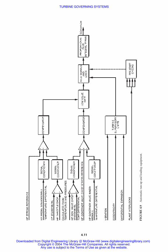
FIG
UR
E 4
.9A
utom
atic
run
-up
and
load
ing
equi
pmen
t.
4.11
TURBINE GOVERNING SYSTEMS
Downloaded from Digital Engineering Library @ McGraw-Hill (www.digitalengineeringlibrary.com)Copyright © 2004 The McGraw-Hill Companies. All rights reserved.
Any use is subject to the Terms of Use as given at the website.
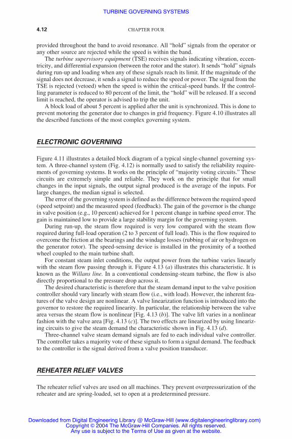
provided throughout the band to avoid resonance. All “hold” signals from the operator orany other source are rejected while the speed is within the band.
The turbine supervisory equipment (TSE) receives signals indicating vibration, eccen-tricity, and differential expansion (between the rotor and the stator). It sends “hold” signalsduring run-up and loading when any of these signals reach its limit. If the magnitude of thesignal does not decrease, it sends a signal to reduce the speed or power. The signal from theTSE is rejected (vetoed) when the speed is within the critical-speed bands. If the control-ling parameter is reduced to 80 percent of the limit, the “hold” will be released. If a secondlimit is reached, the operator is advised to trip the unit.
A block load of about 5 percent is applied after the unit is synchronized. This is done toprevent motoring the generator due to changes in grid frequency. Figure 4.10 illustrates allthe described functions of the most complex governing system.
ELECTRONIC GOVERNING
Figure 4.11 illustrates a detailed block diagram of a typical single-channel governing sys-tem. A three-channel system (Fig. 4.12) is normally used to satisfy the reliability require-ments of governing systems. It works on the principle of “majority voting circuits.” Thesecircuits are extremely simple and reliable. They work on the principle that for smallchanges in the input signals, the output signal produced is the average of the inputs. Forlarge changes, the median signal is selected.
The error of the governing system is defined as the difference between the required speed(speed setpoint) and the measured speed (feedback). The gain of the governor is the changein valve position (e.g., 10 percent) achieved for 1 percent change in turbine speed error. Thegain is maintained low to provide a large stability margin for the governing system.
During run-up, the steam flow required is very low compared with the steam flowrequired during full-load operation (2 to 3 percent of full load). This is the flow required toovercome the friction at the bearings and the windage losses (rubbing of air or hydrogen onthe generator rotor). The speed-sensing device is installed in the proximity of a toothedwheel coupled to the main turbine shaft.
For constant steam inlet conditions, the output power from the turbine varies linearlywith the steam flow passing through it. Figure 4.13 (a) illustrates this characteristic. It isknown as the Willans line. In a conventional condensing-steam turbine, the flow is alsodirectly proportional to the pressure drop across it.
The desired characteristic is therefore that the steam demand input to the valve positioncontroller should vary linearly with steam flow (i.e., with load). However, the inherent fea-tures of the valve design are nonlinear. A valve linearization function is introduced into thegovernor to restore the required linearity. In particular, the relationship between the valvearea versus the steam flow is nonlinear [Fig. 4.13 (b)]. The valve lift varies in a nonlinearfashion with the valve area [Fig. 4.13 (c)]. The two effects are linearized by using lineariz-ing circuits to give the steam demand the characteristic shown in Fig. 4.13 (d).
Three-channel valve steam demand signals are fed to each individual valve controller.The controller takes a majority vote of these signals to form a signal demand. The feedbackto the controller is the signal derived from a valve position transducer.
REHEATER RELIEF VALVES
The reheater relief valves are used on all machines. They prevent overpressurization of thereheater and are spring-loaded, set to open at a predetermined pressure.
4.12 CHAPTER FOUR
TURBINE GOVERNING SYSTEMS
Downloaded from Digital Engineering Library @ McGraw-Hill (www.digitalengineeringlibrary.com)Copyright © 2004 The McGraw-Hill Companies. All rights reserved.
Any use is subject to the Terms of Use as given at the website.
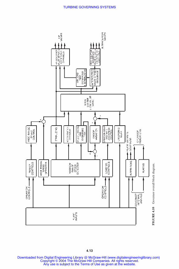
4.13
FIG
UR
E 4
.10
Gov
erno
r ov
eral
l blo
ck d
iagr
am.
TURBINE GOVERNING SYSTEMS
Downloaded from Digital Engineering Library @ McGraw-Hill (www.digitalengineeringlibrary.com)Copyright © 2004 The McGraw-Hill Companies. All rights reserved.
Any use is subject to the Terms of Use as given at the website.

4.14
FIG
UR
E 4
.11
Det
aile
d bl
ock
diag
ram
of
a si
ngle
-cha
nnel
gov
erni
ng s
yste
m.
TURBINE GOVERNING SYSTEMS
Downloaded from Digital Engineering Library @ McGraw-Hill (www.digitalengineeringlibrary.com)Copyright © 2004 The McGraw-Hill Companies. All rights reserved.
Any use is subject to the Terms of Use as given at the website.

4.15
FIG
UR
E 4
.12
Blo
ck d
iagr
am o
f a
thre
e-ch
anne
l gov
erni
ng s
yste
m.
TURBINE GOVERNING SYSTEMS
Downloaded from Digital Engineering Library @ McGraw-Hill (www.digitalengineeringlibrary.com)Copyright © 2004 The McGraw-Hill Companies. All rights reserved.
Any use is subject to the Terms of Use as given at the website.

In addition, on some units, relatively small release valves are used to release steam inthe reheater system to the atmosphere or to the condenser when the governor valves andinterceptor valves close suddenly during an emergency. Although the steam may not be ata sufficiently high pressure to open the relief valves, any residual steam trapped in the HPturbine and reheater could lead to overheating of the blades in the HP turbine due to churn-ing of relatively high-density steam. The release valves are located in the connecting steampiping between the reheater and the interceptor valves. They are signaled to open under cer-tain conditions to prevent overheating of the blades.
4.16 CHAPTER FOUR
FIGURE 4.13 Typical steam load/valve characteristics. (a)Variation of steam flow with the load; (b) Variation of valve areawith steam flow.
TURBINE GOVERNING SYSTEMS
Downloaded from Digital Engineering Library @ McGraw-Hill (www.digitalengineeringlibrary.com)Copyright © 2004 The McGraw-Hill Companies. All rights reserved.
Any use is subject to the Terms of Use as given at the website.

The release valves are actuated hydraulically or pneumatically. If an electronic gover-nor is installed, the release valves open by energizing solenoid valves. They are signaled toopen under the following three conditions:
1. Loss of tripping pressure
2. High shaft acceleration
3. Closure of all interceptor steam relays
These conditions include circumstances of turbine trips or turbine load rejection withouttripping. Churning of the steam could occur either during turbine rundown following a tripor during the period of interceptor valve closure upon a load rejection.
TURBINE GOVERNING SYSTEMS 4.17
FIGURE 4.13 Continued Typical steam load/valve characteris-tics. (c) Variation of valve area with valve lift; (d) Variation of steamdemand with valve lift (known as linearizing characteristic).
TURBINE GOVERNING SYSTEMS
Downloaded from Digital Engineering Library @ McGraw-Hill (www.digitalengineeringlibrary.com)Copyright © 2004 The McGraw-Hill Companies. All rights reserved.
Any use is subject to the Terms of Use as given at the website.
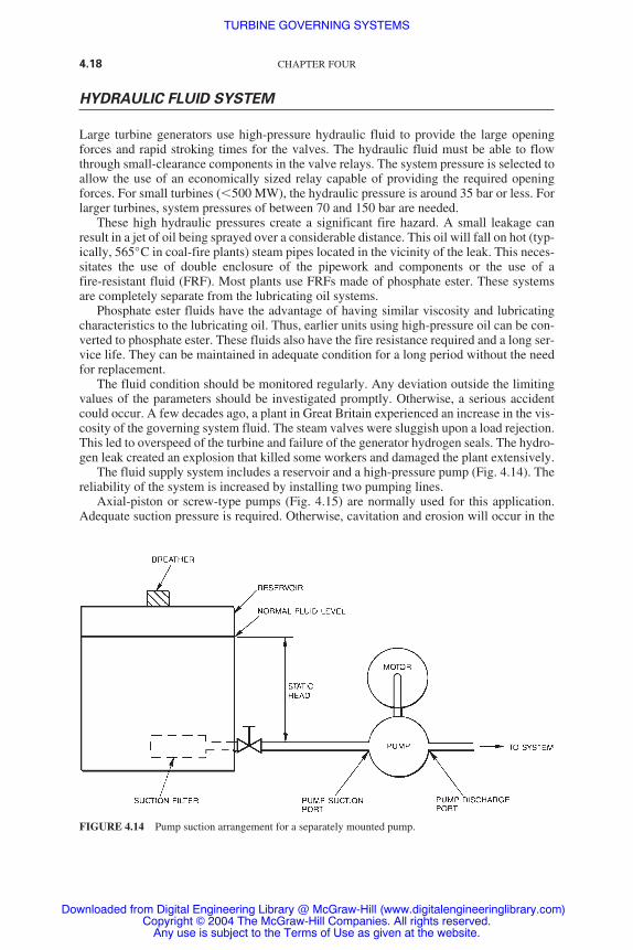
HYDRAULIC FLUID SYSTEM
Large turbine generators use high-pressure hydraulic fluid to provide the large openingforces and rapid stroking times for the valves. The hydraulic fluid must be able to flowthrough small-clearance components in the valve relays. The system pressure is selected toallow the use of an economically sized relay capable of providing the required openingforces. For small turbines (�500 MW), the hydraulic pressure is around 35 bar or less. Forlarger turbines, system pressures of between 70 and 150 bar are needed.
These high hydraulic pressures create a significant fire hazard. A small leakage canresult in a jet of oil being sprayed over a considerable distance. This oil will fall on hot (typ-ically, 565°C in coal-fire plants) steam pipes located in the vicinity of the leak. This neces-sitates the use of double enclosure of the pipework and components or the use of afire-resistant fluid (FRF). Most plants use FRFs made of phosphate ester. These systemsare completely separate from the lubricating oil systems.
Phosphate ester fluids have the advantage of having similar viscosity and lubricatingcharacteristics to the lubricating oil. Thus, earlier units using high-pressure oil can be con-verted to phosphate ester. These fluids also have the fire resistance required and a long ser-vice life. They can be maintained in adequate condition for a long period without the needfor replacement.
The fluid condition should be monitored regularly. Any deviation outside the limitingvalues of the parameters should be investigated promptly. Otherwise, a serious accidentcould occur. A few decades ago, a plant in Great Britain experienced an increase in the vis-cosity of the governing system fluid. The steam valves were sluggish upon a load rejection.This led to overspeed of the turbine and failure of the generator hydrogen seals. The hydro-gen leak created an explosion that killed some workers and damaged the plant extensively.
The fluid supply system includes a reservoir and a high-pressure pump (Fig. 4.14). Thereliability of the system is increased by installing two pumping lines.
Axial-piston or screw-type pumps (Fig. 4.15) are normally used for this application.Adequate suction pressure is required. Otherwise, cavitation and erosion will occur in the
4.18 CHAPTER FOUR
FIGURE 4.14 Pump suction arrangement for a separately mounted pump.
TURBINE GOVERNING SYSTEMS
Downloaded from Digital Engineering Library @ McGraw-Hill (www.digitalengineeringlibrary.com)Copyright © 2004 The McGraw-Hill Companies. All rights reserved.
Any use is subject to the Terms of Use as given at the website.

TURBINE GOVERNING SYSTEMS 4.19
FIGURE 4.15 Typical screw pump and motor assembly.
TURBINE GOVERNING SYSTEMS
Downloaded from Digital Engineering Library @ McGraw-Hill (www.digitalengineeringlibrary.com)Copyright © 2004 The McGraw-Hill Companies. All rights reserved.
Any use is subject to the Terms of Use as given at the website.

pumping system. This will result in a failure of the system and a lengthy outage. A coarsefilter is normally installed at the suction of the screw pump. A separate centrifugal boostpump is also normally used. Its outlet pressure is about 7 bar.
The fluid temperature increases due to the pumping process and being circulatedthrough valve relays adjacent to hot steam pipes. The fluid has optimum conditions at40°C. At higher temperatures, the viscosity will decrease. Excessive leakage from thepump and the system may occur. At still higher temperatures, the fluid starts to breakdown. Conversely, at lower temperatures, the viscosity of the fluid increases. It becomesdifficult to pump. The pressure drop in the system also becomes excessive. The requiredflow rate may not be achieved. For these reasons, heat exchangers are installed in all sys-tems. If cold starting is essential, heaters may also be required. The fluid temperature ismaintained at 40°C at the main pump. Figure 4.16 illustrates a schematic diagram of a typ-ical pumping system.
Filtration
Filtration is required for any fluid supply system. The standards are determined by thesmallest clearances in the system. The purpose of the filters is to remove impurities fromthe system. Impurities are generated continuously within the system from wear inside thepump and other moving components. Some impurities are introduced by the air entering
4.20 CHAPTER FOUR
FIGURE 4.16 Fire-resistant fluid pumping system.
TURBINE GOVERNING SYSTEMS
Downloaded from Digital Engineering Library @ McGraw-Hill (www.digitalengineeringlibrary.com)Copyright © 2004 The McGraw-Hill Companies. All rights reserved.
Any use is subject to the Terms of Use as given at the website.

through the reservoir breather or in the valve relays. Impurities are small particles sus-pended in the fluid. They have irregular size, shape, and chemical composition.
Water should never be introduced into the system during operation and maintenance.The system should also never be cleaned using chlorinated solvents. Nevertheless, waterstill enters the system due to contact of the fluid with air in the reservoir and in the valverelays and drain lines. A vacuum dehydration unit (Fig. 4.17) is normally used to maintainthe water concentration below 2000 parts per million (ppm). The unit takes the fluid fromthe reservoir and then returns the conditioned fluid to the reservoir. The fluid is pumpedfrom the main reservoir into the conditioner reservoir. It is heated to 80°C. Then, it ispassed into a vacuum chamber where the water is extracted. The processed fluid is thenpassed through a Fuller’s earth filter, which reduces the water content further, and also
TURBINE GOVERNING SYSTEMS 4.21
FIGURE 4.17 Fire-resistant fluid conditioner.
TURBINE GOVERNING SYSTEMS
Downloaded from Digital Engineering Library @ McGraw-Hill (www.digitalengineeringlibrary.com)Copyright © 2004 The McGraw-Hill Companies. All rights reserved.
Any use is subject to the Terms of Use as given at the website.

reduces acidity. A trap filter is normally installed after the earth filter. Its main purpose isto capture the earth if the earth filter ruptured accidentally.
Figure 4.18 illustrates an FRF-packaged unit. The joints in the pipework are kept to aminimum. They are welded wherever possible. All pipework is made from stainless steelto avoid corrosion. Interlocks are included to shut down the pumping line if the pump suc-tion pressure or outlet temperature is low.
REFERENCE
1. British Electricity International, Modern Power Station Practice, 3d ed., Pergamon Press, Oxford,United Kingdom, 1991.
4.22 CHAPTER FOUR
FIGURE 4.18 Fire-resistant fluid packaged unit.
TURBINE GOVERNING SYSTEMS
Downloaded from Digital Engineering Library @ McGraw-Hill (www.digitalengineeringlibrary.com)Copyright © 2004 The McGraw-Hill Companies. All rights reserved.
Any use is subject to the Terms of Use as given at the website.

STEAM CHESTS AND VALVES
STEAM CHEST ARRANGEMENTS ANDCONSTRUCTION
The steam leaving the superheater goes through the emergency stop valves (ESVs) andassociated governing valves (GVs) before entering the high-pressure (HP) turbine.1 TheESVs and GVs are housed in steam chests. These steam chests are manufactured fromclosed-die alloy-steel forgings welded together, or from alloy-steel castings. They alsohave simple shapes. This is done to reduce the thermal stresses and hence the possibility ofthermal fatigue.
Similar steam chests house the reheat emergency stop valves (RESVs) and interceptorvalves (IVs). These steam chests are located between the reheater and theintermediate–pressure (IP) turbines. They are manufactured from alloy-steel castings. Theyare thinner but larger than the HP steam chests due to lower steam pressures.
The steam chests are normally mounted alongside the turbine. The four steam mains,together with four ESVs and four GVs, are normally arranged two on each side of the turbine.
Figure. 5.1 illustrates a typical steam chest arrangement of a 660-MW unit. There is asteam chest on each side of the machine. It has an ESV on each end and the two GVs areconnected to the common chamber between the ESVs.
STEAM CHEST MATERIAL
The chests are manufactured from alloy steel. On 660-MW units operating at 565°C, thematerial is usually 0.5 CrMoV steel. In some recent units operating at 538°C, the chestmaterial is 2.25 Cr steel. Higher-chrome ferrite steels with improved creep resistance arealso used on larger units operating at 565°C.
The seats of the valves are of the removable-plate type. These seats are normallyscrewed in place. The mating faces of the valves and their seats are made of Stellite™.This is done to resist wear caused by steam erosion. The wear will occur mainly when thevalve is cracked open. A jet is propelled at high velocity due to the large pressure differ-ential across the narrow port opening. The Stellite facing also provides protection againstimpact damage, which occurs during normal valve closure. It also occurs during frequenthigh-speed test closures. This damage is alleviated normally using cushioning devices inthe relay system or slow-motion testing. Specially treated alloy-steel sleeves in the valvecovers support and guide the valve spindles.
CHAPTER 5
5.1
Downloaded from Digital Engineering Library @ McGraw-Hill (www.digitalengineeringlibrary.com)Copyright © 2004 The McGraw-Hill Companies. All rights reserved.
Any use is subject to the Terms of Use as given at the website.
Source: POWER GENERATION HANDBOOK

FIG
UR
E 5
.1T
ypic
al s
team
che
st a
rran
gem
ents
.
5.2
STEAM CHESTS AND VALVES
Downloaded from Digital Engineering Library @ McGraw-Hill (www.digitalengineeringlibrary.com)Copyright © 2004 The McGraw-Hill Companies. All rights reserved.
Any use is subject to the Terms of Use as given at the website.

STEAM STRAINERS
Each ESV is surrounded by a cylindrical strainer. The strainer has many 2- to 5-mm-diameterholes. It prevents solid particles of foreign matter from getting entrained with the steamentering the turbine. These particles could cause serious damage to the turbine blading ifthey enter the turbine. It is essential to have a thorough steam blow of all pipework beforecommissioning a plant.
EMERGENCY STOP VALVES
The two purposes of the ESVs (also known as stop valves) are:
1. To interrupt the steam flow promptly during an emergency trip
2. To cut off the steam supply when the unit is shut down
The valves are tested on-power regularly (at least once a month) to ensure they will closeduring an emergency. The load is reduced during this testing. The valves are tested insequence, one at a time, during the on-load testing.
The ESV is normally a single-seated unbalanced plug-type valve. It has an internalsmall pilot valve that opens first. The pilot valve can be opened against main steam pres-sure. It is also used during run-up because the steam flow is from 1 to 2 percent of the full-load steam flow. It also reduces the force required to actuate the valve. When the machinereaches operating speed, the GVs, which have been open, close in. At this stage, it is pos-sible to open the ESVs because the upstream and downstream pressure of the valve havebeen equalized. Figure 5.2 illustrates a typical ESV. Flap valves are used as reheat emer-gency stop valves (RESVs) for some 500 and 660 MW units. The steam in these valves hasmoderate pressure and large specific volume.
GOVERNOR VALVES
The governor valves control the steam flow entering the turbine. Since the generator con-verts mechanical energy to electrical energy, the governor valves control the generator loadwhen the machine is synchronized to the grid.
Modern power plants use the governor valves to throttle the steam flow during turbinerun-up to speed. However, earlier machines use pilot valves in the ESV in conjunctionwith the governor valves during run-up (the steam flow during run-up is less than 2 per-cent of the steam flow required during full-load operation). Figure 5.3 illustrates a typicalgovernor valve.
REFERENCE
1. British Electricity International, Modern Power Station Practice, 3d ed., Pergamon Press, Oxford,United Kingdom, 1991.
STEAM CHESTS AND VALVES 5.3
STEAM CHESTS AND VALVES
Downloaded from Digital Engineering Library @ McGraw-Hill (www.digitalengineeringlibrary.com)Copyright © 2004 The McGraw-Hill Companies. All rights reserved.
Any use is subject to the Terms of Use as given at the website.

5.4 CHAPTER FIVE
FIGURE 5.2 Typical emergency stop valve. (*, shown out of position.)
STEAM CHESTS AND VALVES
Downloaded from Digital Engineering Library @ McGraw-Hill (www.digitalengineeringlibrary.com)Copyright © 2004 The McGraw-Hill Companies. All rights reserved.
Any use is subject to the Terms of Use as given at the website.
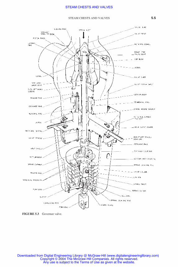
STEAM CHESTS AND VALVES 5.5
FIGURE 5.3 Governor valve.
STEAM CHESTS AND VALVES
Downloaded from Digital Engineering Library @ McGraw-Hill (www.digitalengineeringlibrary.com)Copyright © 2004 The McGraw-Hill Companies. All rights reserved.
Any use is subject to the Terms of Use as given at the website.

STEAM CHESTS AND VALVES
Downloaded from Digital Engineering Library @ McGraw-Hill (www.digitalengineeringlibrary.com)Copyright © 2004 The McGraw-Hill Companies. All rights reserved.
Any use is subject to the Terms of Use as given at the website.
TURBINE PROTECTIVEDEVICES
POSSIBLE HAZARDS
Abnormal turbine operating conditions will cause damage to the plant and possibly to per-sonnel if allowed to persist.1 The possible dangers include the following:
● Overspeeding● Lubricating oil failure● High turbine exhaust pressure (low condenser vacuum)● Governor failure● Water ingress to blading● Thrust bearing failure● Excessive vibration● Excessive temperature differentials● Excessive eccentricity
Supervisory equipment normally monitors the last four items. The remaining dangers havemore immediate effects on the plant. They are detected by systems that depressurize thehydraulic pressure of the governing system. This results in shutting the steam valves anddisconnecting of the generator.
The preceding list includes dangers that only affect the turbine. Other hazards specificto the boilers, generator, transformers, and high-voltage connections can also initiate a tur-bine generator trip.
The consequences of overspeed are very serious for the plant and personnel. Therefore,the protective systems have been designed to prevent overspeed. The turbine governingsystem protects the unit from overspeed. However, if it malfunctions, a separate overspeedtripping system will become activated. When the generator is connected to the grid, the tur-bine cannot overspeed (the generator is coupled magnetically with the grid). The possibil-ity of overspeed occurs during run-up and when the unit is disconnected suddenly from theload (during a load rejection). The unit is normally disconnected from the grid due to aninternal problem such as a loss of lubricating oil. The possibility of overspeed is normallyreduced by coordinating the opening of the circuit breaker and the closure of the steamvalves. The turbine will overspeed when the torque generated by the steam flow exceedsthe countertorque generated by the load. Thus, whenever possible, the steam valves shouldclose while the unit is still connected to the grid.
When the steam flow drops below the one required to overcome friction losses [bear-ings and windage (rubbing of air or hydrogen against the generator rotor)], the generator
CHAPTER 6
6.1
Downloaded from Digital Engineering Library @ McGraw-Hill (www.digitalengineeringlibrary.com)Copyright © 2004 The McGraw-Hill Companies. All rights reserved.
Any use is subject to the Terms of Use as given at the website.
Source: POWER GENERATION HANDBOOK

starts to act as a motor. It starts to pull current from the grid to continue running at the oper-ating speed. The circuit breaker now opens on reverse power. This sequence of activitiesprevents the chance of overspeed. This type of a trip is known as category B trip. If thesteam valves fail to close and the generator gets disconnected from the grid, the unit willsuffer disastrous consequences. However, if the generator remains connected to the gridwhen the steam valves fail to close, the turbine will not overspeed. The unit can be shutdown safely by closing the boiler stop valves. All tripping conditions that follow thissequence of events are known as category B trips. They include the following:
● Governor failure● Lubricating oil failure● Overspeed● Water ingress● Manual emergency stop
Other trips, such as turbine high–exhaust pressure trips and some electrical trips, requireimmediate disconnection of the generator from the grid. These trips are known as categoryA trips. If the turbine exhaust pressure is high, the last stage of the blades in the low-pressure(LP) turbine will become overheated and damaged. The turbine unloading gear (includedin the governing system) reduces the turbine load to avoid tripping. Some units use LPexhaust temperature sprays. They are activated when high temperature is detected. Theyare also used when the turbine load drops below a predetermined value. The possibility ofheating the turbine blading at low load is high. This is due to the low flow that is unable toremove the heat generated. The LP turbine also has bursting diaphragms fitted in the cas-ing. They operate at a pressure slightly higher than atmospheric.
Alternating-current (AC) and standby direct-current (DC) pumps ensure continuoussupply of lubricating oil to the bearings. However, in case of a pipe fracture, the turbine istripped on low lubricating oil pressure. If the governing system fails (e.g., due to failure ofmore than one channel), a tripping signal is sent to the protection scheme.
Water can enter the turbine due to malfunction of the boiler or feed controls. This eventhas a higher probability of occurrence during load variations. Wet steam or even slugs ofwater could enter the high-pressure (HP) steam line. The protection required varies with theboiler type and the degree of hazard. If superheated steam is supplied from a steam drum,turbine protection may not be required if the loss of boiler firing can be adequately detectedand alarmed. In this case, the operator can take the necessary corrective action.
If superheated steam is supplied from a once-through boiler, the turbine should betripped on low steam temperature before saturated steam reaches the turbine. If the turbineis not tripped in this case, the turbine blades could become fractured. The sudden ingressof wet steam could generate significant axial (thrust) loads on the turbine blading. Thus, theplant must be designed to accept this condition or be protected against it. Water can alsoenter the turbine from the feedheaters (backflow). This can occur upon a load rejection. Inthis case, the pressure inside the turbines drops to a lower value than the one in the feed-heaters. Check valves are installed on the extraction lines to the feedheaters to prevent thisreverse flow.
PROTECTION SCHEME
There are two types of trip-initiating devices:
1. Devices that are operated by an electrical changeover contact
6.2 CHAPTER SIX
TURBINE PROTECTIVE DEVICES
Downloaded from Digital Engineering Library @ McGraw-Hill (www.digitalengineeringlibrary.com)Copyright © 2004 The McGraw-Hill Companies. All rights reserved.
Any use is subject to the Terms of Use as given at the website.

2. Devices that are capable of tripping the hydraulic fluid system directly
A trip closes the turbine steam valves and opens the generator circuit breaker. As explainedearlier, the trips are divided into categories A and B. Redundancy is built into the trippingsystem. The failure of one element in the system does not prevent tripping. The systemincludes features to avoid spurious tripping as much as possible. Figure 6.1 illustrates themain functions of the hydraulic tripping system.
The interfaces with the electrical tripping system and the relays of the emergency stopvalves (ESVs) and governing valves (GVs) are also shown. The redundancy of the electri-cal tripping system is not shown.
The unit has two sets of emergency trip valves and trip plungers. Each set is associatedwith a set of overspeed trip bolts mounted in the turbine shaft. High-pressure fluid is sup-plied to the emergency trip valves. If either valve is caused to trip (i.e., move to the left),the protection fluid will be connected to drain via pipe A or pipe B. This results in the clo-sure of all turbine steam valves. The pressure of the control fluid is maintained to avoidexcess fluid consumption from the fire-resistant fluid (FRF) supply unit.
Spring-loaded trip plungers operate the emergency trip valves. During normal opera-tion, a spigot maintains the spring in compression. The spigot is held in place by the Y-shaped trip arm and latch. When the overspeed trip is initiated, the manual trip or thesolenoid trip releases the spring-loaded latch. Thus, the protection fluid at high pressure inthe chamber located at the left-hand end of the emergency trip valve is released to drain. Itcauses the valves to move to the tripped position. It should be noted that when one over-speed trip occurs, the fluid on the corresponding side of the interlock unit will go to drain.The piston in the interlock unit will move, forcing the second emergency trip valve to trip.Additional hydraulic units (not shown) are used to reset the trip plungers and latches before
TURBINE PROTECTIVE DEVICES 6.3
FIGURE 6.1 Hydraulic trip unit—simplified block diagram. Notes: (1) Shown in the normal-running,untripped condition. (2) Isolating and reset facilities not shown.
TURBINE PROTECTIVE DEVICES
Downloaded from Digital Engineering Library @ McGraw-Hill (www.digitalengineeringlibrary.com)Copyright © 2004 The McGraw-Hill Companies. All rights reserved.
Any use is subject to the Terms of Use as given at the website.

subsequent trip run-up. Regular on-load testing is done to identify and rectify any faults inthe tripping system.
OVERSPEED TRIP
The overspeed trip is initiated when the governing system fails to limit the speed rise of theturbine shaft. It is the final line of defense to prevent a catastrophic failure of the turbine.Turbine overspeed can occur following a load rejection (when the unit becomes discon-nected from the grid). It can also occur when the unit is operating in the islanding (unsyn-chronized) mode. If the governing system fails, higher steam flow can enter the turbine,leading to overspeed.
If the overspeed becomes excessive (approaching 100 percent), the centrifugal forcesacting on the rotating parts become extremely high. The blades will start to rupture and penetrate through the casing. The manufacturer normally performs an overspeed test at
6.4 CHAPTER SIX
FIGURE 6.2 Overspeed governor.
TURBINE PROTECTIVE DEVICES
Downloaded from Digital Engineering Library @ McGraw-Hill (www.digitalengineeringlibrary.com)Copyright © 2004 The McGraw-Hill Companies. All rights reserved.
Any use is subject to the Terms of Use as given at the website.

120 percent of the speed. This speed is significantly lower than the design limit at whichblade rupture could occur (180 to 200 percent overspeed). The overspeed trip is normallyset in the range from 110 to 112.5 percent speed.
A pair of spring-loaded trip bolts are used to detect the overspeed. They are mounted inan extension of the shaft at the HP turbine end (Fig. 6.2). Each trip channel is associatedwith one trip bolt assembly. Each assembly can be tested on-load. The center of gravity ofthe bolt is located at a short distance from the axis of rotation. At normal speeds, the bolt isheld in place by a spring. When the overspeed trip set point is reached, the centrifugal forceacting on the bolt overcomes the spring force. The bolt extends beyond the shaft. It trips thestatic trip lever and releases a latch that trips the turbine. The tripping speed is adjustedwhen the turbine is stationary.
The overspeed trip test can be performed without actually overspeeding the turbine ortaking the set off-load. The “front” or “rear” system is selected for testing. This action auto-matically isolates the associated emergency trip valve. A supply of lubricating oil underpressure is injected into the rotating turbine shaft. It flows through porting to the overspeedbolt being tested. The bolt moves out and trips its emergency trip valves via the lever andtrip plunger. The test pressure is then released. The aforementioned items are reset, and thesecond bolt is tested.
REFERENCE
1. British Electricity International, Modern Power Station Practice, 3d ed., Pergamon Press, Oxford,United Kingdom, 1991.
TURBINE PROTECTIVE DEVICES 6.5
TURBINE PROTECTIVE DEVICES
Downloaded from Digital Engineering Library @ McGraw-Hill (www.digitalengineeringlibrary.com)Copyright © 2004 The McGraw-Hill Companies. All rights reserved.
Any use is subject to the Terms of Use as given at the website.

TURBINE PROTECTIVE DEVICES
Downloaded from Digital Engineering Library @ McGraw-Hill (www.digitalengineeringlibrary.com)Copyright © 2004 The McGraw-Hill Companies. All rights reserved.
Any use is subject to the Terms of Use as given at the website.

TURBINE INSTRUMENTATION
INSTRUMENTATION CATEGORIES
The six categories of turbine instrumentation are1
1. Supervisory instrumentation
2. Efficiency instrumentation
3. Auxiliary system instrumentation
4. Condition-monitoring instrumentation
5. Instrumentation associated with protection and control equipment
6. Instrumentation to provide postincident records
The most important of these six categories are supervisory and efficiency instrumentation.This is due to the significant role they play in monitoring plant safety and power production.
Supervisory Instrumentation
The supervisory instruments are required continuously to determine the condition of themain rotating and stationary components. The main functions of supervisory instrumentsinclude the following:
1. To ensure safe operation within acceptable limits.2. To provide advanced warning of deterioration in the performance of the turbine gener-
ator. Maintenance or temporary restriction in the operating mode may be required. Themeasured parameters include the following:a. Rotor axial position. These measurements provide the relative axial movement of
the rotor. They are used to ensure that clearance margins are maintained under alloperating conditions. These measurements are normally taken on each cylinder of themachine.
b. Cylinder expansions. These measurements provide the relative radial movementbetween the rotors and the stators. They are used to ensure that radial clearance mar-gins are maintained under all operating conditions. These measurements are nor-mally taken on each cylinder of the machine.
c. Bearing pedestal vibrations. These measurements are taken at each bearing. Theycontinuously monitor the dynamic behavior of the machine.
d. Shaft eccentricity. The radial excursion of the rotor (peak-to-peak) relative to thestationary parts is measured on each rotor. This is done to indicate abnormal orunsafe conditions.
CHAPTER 7
7.1
Downloaded from Digital Engineering Library @ McGraw-Hill (www.digitalengineeringlibrary.com)Copyright © 2004 The McGraw-Hill Companies. All rights reserved.
Any use is subject to the Terms of Use as given at the website.
Source: POWER GENERATION HANDBOOK

e. Shaft speed. The shaft speed is measured independently of the turbine governor.This measurement is used for operator reference. It is mainly used during run-up.
f. Steam valve positions. The position of each steam valve is measured. These mea-surements are used as a general reference for the operator. They are used to deter-mine if the load can be increased or for diagnostic purposes.
g. Metal temperature measurements. The temperature of the turbines is measuredduring normal operation and transient states. The instruments are located in the high-pressure (HP) and interceptor steam valve chests, and in the cylinders of the HP andintermediate-pressure (IP) turbines.
h. Thrust bearing wear. These measurements are taken to ensure that the wear of thethrust pads is within acceptable limits. If the wear is higher than the acceptable limit,the turbine generator rotor will move with respect to the stator. This could have dis-astrous consequences on the machine.
All of the measured parameters are displayed continuously for the operator.
Efficiency Instrumentation
These instruments are used to determine or infer the thermal efficiency of the plant. Theinformation is stored to determine the long-term trends. The temperatures and pressures ofsteam and water are measured at different locations throughout the plant. These measure-ments are taken to ensure that plant equipment is operating efficiently. For example, theconditions of steam and water at the inlet and outlet to the feedwater heaters are measured.Unsatisfactory operation will not likely result in shutdown of the plant; however, it willresult in decreased efficiency.
REFERENCE
1. British Electricity International, Modern Power Station Practice, 3d ed., Pergamon Press, Oxford,United Kingdom, 1991.
7.2 CHAPTER SEVEN
TURBINE INSTRUMENTATION
Downloaded from Digital Engineering Library @ McGraw-Hill (www.digitalengineeringlibrary.com)Copyright © 2004 The McGraw-Hill Companies. All rights reserved.
Any use is subject to the Terms of Use as given at the website.

LUBRICATION SYSTEMS
LUBRICATION REQUIREMENTS AND TYPICALARRANGEMENTS
The turbine bearings must be lubricated to prevent damage that is caused by wear orincreased temperatures.1 It is necessary to lift the turbine generator shaft before starting toturn the shaft. The jacking oil system is used to provide this function.
The purposes of bearing lubrication are as follows:
1. To provide a hydrodynamic oil wedge between the bearing and the shaft.2. To provide an oil flow to maintain the white metal of the bearing below 110°C. The
sources of heat inside the bearing include:a. Thermal conductionb. Friction between the oil film, the journal (portion of the shaft inside the bearing), and
the white metal of the bearingc. Turbulence within the oil itself
The oil temperature leaving the bearing is normally limited to 71°C. Older units usedthe same oil for lubrication and turbine control and protection (Fig. 8.1). Modern units usefire-resistant fluid (FRF) with a pressure of 7 to 17.5 Megapascals (MPa) for the turbinecontrol system. Figure 8.2 illustrates the lubrication oil system of a modern unit. A directlydriven centrifugal pump delivers oil at 1.1 MPa. The oil from this pump goes through anoil turbine. The oil pressure is reduced across the turbine to 0.3 MPa. The oil turbine dri-ves a booster pump that supplies oil from the main tank to the suction of the centrifugal oilpump. The system is protected against overpressurization by a relief valve mounted on theoil tank. The relief valve is connected to the bearing oil supply line. During normal opera-tion, the directly driven main oil pump provides a highly reliable source of lubrication oil.The alternating-current (AC) auxiliary oil pump provides lubrication during start-up andshutdown. The direct-current (DC) auxiliary pump provides lubrication during emergencyshutdown (upon loss of AC supplies) or when the AC pump fails to start. Lubrication oil isalso supplied to the generator hydrogen seals from this system. However, most modernunits have a separate seal oil system to prevent contaminating the main oil with hydrogen.On these units, the supply from the main lubricating oil is used as a backup to the seal oilsystem. On modern units, the lubricating oil system supplies the following:
● Each journal bearing of the turbine, generator, and exciter.● The main thrust surge bearing.● The generator hydrogen seal (this is either a sole supply or a backup system).● The bearings on the turbine-driven boiler feed pump (in plants having this feature).● The lubricating oil system also has filters, strainer, coolers, and tank vents.
CHAPTER 8
8.1
Downloaded from Digital Engineering Library @ McGraw-Hill (www.digitalengineeringlibrary.com)Copyright © 2004 The McGraw-Hill Companies. All rights reserved.
Any use is subject to the Terms of Use as given at the website.
Source: POWER GENERATION HANDBOOK

FIG
UR
E 8
.1L
ubri
catin
g an
d re
lay
oil s
yste
m f
or a
n ol
der
turb
ine
gene
rato
r pl
ant.
No.
1N
o. 4
No.
16N
o. 5N
o. 6N
o. 7N
o. 8N
o. 9N
o. 10N
os. 1
1-15
No.
2 N
o. 3
TH
RU
ST
GE
AR
CA
SE
BR
GS
.
MA
IN O
IL P
RE
SS
UR
E F
EE
DM
AIN
OIL
DR
AIN
SJA
CK
ING
OIL
MA
KE
UP
OIL
AU
XIL
IAR
Y O
IL F
EE
D
JAC
KIN
G O
IL D
RA
INS SU
PP
LY T
OO
TH
ER
UN
ITS
FF
LOW
ME
TE
R
FLU
X V
ALV
E
HIG
H-P
RE
SS
UR
EO
IL P
UM
P
HO
SE
CO
UP
LIN
GF
OR
TAN
KE
RS
UP
PLY
OIL
ST
OR
AG
ETA
NK
ST
RA
INE
R
OIL
SE
RV
ICIN
G T
AN
K
RE
LIE
FT
O T
AN
K
OIL
FIL
TE
R
TAN
KE
RC
ON
NE
CT
ION
SLU
ICE
VA
LVE
S
TO
PP
ING
UP
MA
IN
OIL
DR
AIN
CO
NN
EC
TIO
N
DC
EM
ER
GE
NC
YLU
BR
ICA
TIO
NO
IL P
UM
P
AC
TU
RN
ING
GE
AR
OIL
PU
MP
OIL
CO
OLE
RR
ELI
EF
VA
LVE
OIL
CO
OLE
RS
FIL
TE
RC
HA
MB
ER
AC
AU
XIL
IAR
YO
IL P
UM
P
OIL
JE
T P
UM
P
WO
RK
ING
OIL
LE
VE
L
OIL
RE
LIE
FT
O T
AN
K
OIL
LE
VE
LIN
DIC
AT
OR
AU
X O
ILP
UM
PR
EG
ULA
TO
R
PU
MP
PR
ES
SU
RE
CO
NT
RO
L V
ALV
E
TO
OIL
RE
LAY
&S
EA
L O
IL S
YS
TE
M
MA
IN O
ILP
UM
P
VA
PO
RE
XT
RA
CT
'R
ST
RA
INE
R
OIL
PU
RIF
ICA
TIO
NS
YS
TE
M
8.2
LUBRICATION SYSTEMS
Downloaded from Digital Engineering Library @ McGraw-Hill (www.digitalengineeringlibrary.com)Copyright © 2004 The McGraw-Hill Companies. All rights reserved.
Any use is subject to the Terms of Use as given at the website.

8.3
FIG
UR
E 8
.2L
ubri
catin
g oi
l sys
tem
for a
mod
ern
turb
ine
gene
rato
r pla
nt.
LUBRICATION SYSTEMS
Downloaded from Digital Engineering Library @ McGraw-Hill (www.digitalengineeringlibrary.com)Copyright © 2004 The McGraw-Hill Companies. All rights reserved.
Any use is subject to the Terms of Use as given at the website.

The lubricating oil tank of the unit is connected to the following:
● Clean-oil tank● Dirty-oil tank● Oil purification system
The pumps and pipework permit the transfer of oil as follows:
● From the clean-oil tank to the unit oil tank through the oil purification unit● From the used-oil tank to the unit oil tank through the oil purification unit● To drain all of the oil in the system into the unit oil tank● To move all of the oil from the unit oil tank to the station used-oil tank● To move all of the oil from the road oil tanker into the station clean-oil tank● To move the oil from the station used-oil tank to a road oil tanker● To process the oil in the unit tank or the oil in the station clean-oil tank through the
purifier● To process the oil in the unit tank or the station clean-oil tank through a portable oil
purifier unit
Figure 8.3 illustrates a schematic arrangement of the equipment used.
OIL PUMPS
Main Lubricating Oil Pump
The main lubricating oil pump is normally directly driven from the main shaft. This ensuresa highly reliable oil supply. Figure 8.4 illustrates a typical centrifugal pump used as a mainlubricating oil pump in modern units. The oil flow is around 100 L/s (for a 660-MW unit).The suction pressure is around 0.3 to 0.4 MPa.
Turbine-Driven Oil Booster Pump
The oil leaving the main oil pump goes through an oil turbine to increase the reliability ofthe lubricating oil supply. The oil turbine is mounted on top of the oil tank. It drives a sub-merged centrifugal pump, which delivers the oil to the suction of the main oil pump.
AC and DC Motor-Driven Auxiliary Oil Pumps
The AC auxiliary oil pump supplies oil to the bearings during start-up and normal shut-down. The DC pump supplies oil to the bearings during an emergency shutdown (when ACpower is lost). These are centrifugal pumps with a submerged suction. They are also sus-pended from the top of the tank. Their arrangement is similar to the one in Fig. 8.5, but theoil turbine is replaced with an AC or DC motor. The AC auxiliary pump delivers the oil ataround 0.3 MPa. It also primes the main oil pump. The AC and DC pumps have a capacityof around 7 to 12 L/s.
8.4 CHAPTER EIGHT
LUBRICATION SYSTEMS
Downloaded from Digital Engineering Library @ McGraw-Hill (www.digitalengineeringlibrary.com)Copyright © 2004 The McGraw-Hill Companies. All rights reserved.
Any use is subject to the Terms of Use as given at the website.

FIG
UR
E 8
.3L
ubri
catin
g oi
l tra
nsfe
r an
d co
nditi
onin
g sy
stem
.
8.5
LUBRICATION SYSTEMS
Downloaded from Digital Engineering Library @ McGraw-Hill (www.digitalengineeringlibrary.com)Copyright © 2004 The McGraw-Hill Companies. All rights reserved.
Any use is subject to the Terms of Use as given at the website.

Jacking Oil Pumps and Priming Pumps
The jacking oil pumps deliver oil at around 30 MPa to the bearings. These are motor-drivenpositive-displacement pumps. They are either multiplunger pumps (Fig. 8.6) or two-shaftgear pumps (Fig. 8.7).
OIL TANKS
The main oil tank (Fig. 8.8) has a capacity of 75 m3 in modern units. The normal workingvolume is around 50 m3. Baffle plates separate the returning oil to the tank and the pumpsuction in order to assist in deaeration and settlement. It also prevents the formation of stag-nant oil pockets. The tank is designed to provide around 7 min for oil transit time betweenreturn and suction. The trend in modern units is to provide a self-contained section of thetank for the hydrogen seal system. This is done to eliminate the possibility of hydrogen gasentering the main lubricating oil system. If the lubricating oil system is used to provide the
8.6 CHAPTER EIGHT
FIGURE 8.4 Main lubricating oil pump.
LUBRICATION SYSTEMS
Downloaded from Digital Engineering Library @ McGraw-Hill (www.digitalengineeringlibrary.com)Copyright © 2004 The McGraw-Hill Companies. All rights reserved.
Any use is subject to the Terms of Use as given at the website.
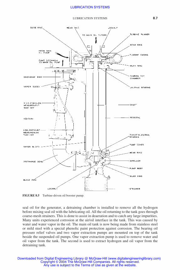
seal oil for the generator, a detraining chamber is installed to remove all the hydrogenbefore mixing seal oil with the lubricating oil. All the oil returning to the tank goes throughcoarse-mesh strainers. This is done to assist in deaeration and to catch any large impurities.Many units experienced corrosion at the air/oil interface in the tank. This was caused bywater and water vapor in the oil. The main oil tank is now being made from stainless steelor mild steel with a special phenolic paint protection against corrosion. The bearing oilpressure relief valves and two vapor extraction pumps are mounted on top of the tankbeside the suspended oil pumps. One vapor extraction pump is used to remove water andoil vapor from the tank. The second is used to extract hydrogen and oil vapor from thedetraining tank.
LUBRICATION SYSTEMS 8.7
FIGURE 8.5 Turbine-driven oil booster pump.
LUBRICATION SYSTEMS
Downloaded from Digital Engineering Library @ McGraw-Hill (www.digitalengineeringlibrary.com)Copyright © 2004 The McGraw-Hill Companies. All rights reserved.
Any use is subject to the Terms of Use as given at the website.

8.8 CHAPTER EIGHT
FIGURE 8.6 Multiplunger jacking oil pump.
FIGURE 8.7 Gear-type jacking oil/priming pump.
8.8
LUBRICATION SYSTEMS
Downloaded from Digital Engineering Library @ McGraw-Hill (www.digitalengineeringlibrary.com)Copyright © 2004 The McGraw-Hill Companies. All rights reserved.
Any use is subject to the Terms of Use as given at the website.

PIPING
Special design precautions against oil leakage and fire hazards are taken for piping used injacking oil and lubricating oil systems. The oil piping is sized to have a velocity between 1 and 5 m/s. An enclosure or a duct is installed around the oil piping at the pump discharge.The number of pipe joints is minimized by maximizing the length of pipe runs. All pipejoints are welded class 1 type. At the exit from the ducted area, a protective pipe is installedaround the pressure oil pipe. This is done to contain and detect any oil leakage. The pipingbetween the pump and the filters is made of mild steel. Some units use stainless-steel pip-ing after the filters to minimize corrosion. If the air is not vented through the bearings, anautomatic air venting of the piping from its highest points to the oil tank is installed. Airvents to the oil tank are installed on the oil filters. They vent any air that accumulates dur-ing operation or maintenance to the oil tank.
OIL COOLERS
The function of the coolers (heat exchangers) is to lower the temperature of the oil leav-ing the bearings below the acceptable limit. Redundant coolers are provided to allowmaintenance to be performed while the unit is operating. The normal arrangements are
LUBRICATION SYSTEMS 8.9
FIGURE 8.8 Main oil tank—general arrangement.
LUBRICATION SYSTEMS
Downloaded from Digital Engineering Library @ McGraw-Hill (www.digitalengineeringlibrary.com)Copyright © 2004 The McGraw-Hill Companies. All rights reserved.
Any use is subject to the Terms of Use as given at the website.

three 50 percent or two 100 percent coolers. The oil coolers are installed vertically. Thewater flows through the tube in a two-pass arrangement. The oil flows on the shell side ofthe coolers through a series of baffles. In modern units, the shells of the coolers are madeof mild steel and the tubes of titanium. The tube bundle has a floating tube plate to accom-modate thermal expansion. The coolers also have end plates. They permit cleaning of thecoolers without dismantling the water pipes. The heat dissipated by each cooler is around2 MW. The oil filters are integral with the cooler shell on some units (Fig. 8.9). An auto-matic bypass of the oil coolers is normally installed. It allows the oil to bypass the coolerupon an excessive pressure drop across the cooler. The automatic control system is basedon the oil outlet temperature.
OIL STRAINER AND FILTERS
The oil strainers are basket-type assemblies made of coarse wire mesh. They are designed tocatch large impurities entering the main oil tank. They ensure that the flow reaching the suc-tion of the pump will not damage the pump. The strainers can be lifted out of the tank toremove and inspect the collected debris. The two main systems of lubricating oil filtration are
1. Cartridge filters. The cartridge filters fit into the casing of the oil cooler. Each cartridgeis designed to filter 13 L/s of hot oil. The nominal particle size is 10 �m. Each cooler usesup to 4 disposable cartridges. Only two coolers are required for 100 percent duty.
2. Duplex filters. The duplex filters are installed after the oil coolers. Multiple dispos-able filters are used sometimes in this application. They have facilities for on-loadreplacement. Duplex plate filters are also used in this application. They can be
8.10 CHAPTER EIGHT
C.W. INLET
C.W. OUTLET
BOSS FORTHERMO POCKET
BOSS FORDISTANCETHERMOMETER
BOSS FOR DISTANCETHERMOMETER
BOSS FOR DISTANCETHERMOMETER
WATERBOX COVER
INLET/OUTLETWATERBOX
TOP TUBEPLATE
OIL OUTLET
OIL INLET
BAFFLE PLATES
COOLER BODY
RETURN WATERBOX
BOTTOM TUBEPLATEFILTER ELEMENTS
DIFFERENTIAL PRESSUREGAUGE CONNECTIONS
FILTER CHAMBER AIRRELEASE CONNECTION
FILTER CHAMBER
BOSS FORTHERMO POCKET
FILTER CHAMBERACCESS COVERS
OILINLET
OIL DRAIN
WATER DRAIN
OIL OUTLET
C.W. INLET C.W. OUTLET
BAFFLE PLATES
TUBES
FLOW DIAGRAM
WATERBOX AIRRELEASE CONNECTIONS
COOLER BODY AIRRELEASE CONNECTIONS
TUBENEST
FIGURE 8.9 Oil cooler with integral filter.
LUBRICATION SYSTEMS
Downloaded from Digital Engineering Library @ McGraw-Hill (www.digitalengineeringlibrary.com)Copyright © 2004 The McGraw-Hill Companies. All rights reserved.
Any use is subject to the Terms of Use as given at the website.

cleaned on-load. There are two compartments in the plate-type filter. Each compart-ment has five filter assemblies. Each assembly is made of a series of plates and spac-ers. The degree of filtration is 75 �m. Each compartment receives half the oil flow.The filter has facilities to allow all the flow to go through one compartment. This con-figuration is used during on-load replacement, inspection, or maintenance of onecompartment. During normal operation, the filter capacity is around 106 L/s under apressure drop of 0.3 bar.
The filter is normally cleaned automatically when the pressure differential reaches 0.45bar across the filter. Each plate filter assembly is rotated against a scraper bar. The debrisfrom each filter falls into a sump at the bottom of the filter housing. The sump is cleanedout regularly. Figure 8.10 illustrates a typical plate-type filter. If a plate-type filter is used,additional filtration is required for the oil supply to:
● The thrust bearings● The turning gear, jacking oil pump, gearing, and clutch● The main oil pump, thrust bearing, and cooling sprays
The oil being supplied for these duties is taken from the discharge of the filter andpassed through an additional duplex plate-type filter similar to the one shown in Fig. 8.10.There are four plate filter assemblies in each compartment of this additional filter. It canonly be cleaned manually. The normal flow through the filter is 16 L/s under a pressuredrop of 0.2 bar with both compartments in service.
OIL PURIFIERS AND COALESCERS
The steam leaking from the turbine glands represents the main source of contamination forthe lubricating oil. The steam condenses when it comes in contact with the bearing hous-ing. The condensate becomes dispersed through the oil. The used oil normally containswear particles, oxides, soluble acids, and sludge. These impurities must be removed fromthe oil to extend its life and maintain adequate lubrication. During normal operation, thereare two main systems used on bypass duty continuously. There is also an oil regenerationsystem. The on-line systems used include centrifugal separation systems and static oil puri-fiers/coalescers.
Centrifugal Separation Systems
The centrifugal separation systems have been used for many years. They require consider-able maintenance and careful adjustment for best effectiveness. Figure 8.11 illustrates atypical arrangement of this system. It operates based on the principle that if a mixture iscentrifuged, the fluids settle out radially with the fluid having the highest specific gravityoutermost. Dirty oil from the main oil tank is delivered to the purifier. It passes through aregenerative heater/cooler. It is heated to 75°C. This is the best temperature for centrifugalseparation. The oil enters the separator bowl. Centrifugal force separates the mixture intoits different densities. The clean oil is collected by inverted cones (Fig. 8.12). It is deliveredto the clean-oil outlet. The water and acids are discharged from the separator. The solidsaccumulate at the bottom of the bowl and are discharged regularly. The clean hot oil entersthe regenerative heater or cooler. It is then returned to the main oil tank. The oil flow ratethrough the purifier is around 10 percent of the total oil inventory per hour.
LUBRICATION SYSTEMS 8.11
LUBRICATION SYSTEMS
Downloaded from Digital Engineering Library @ McGraw-Hill (www.digitalengineeringlibrary.com)Copyright © 2004 The McGraw-Hill Companies. All rights reserved.
Any use is subject to the Terms of Use as given at the website.

Static Oil Purifiers/Coalescers
Figure 8.13 illustrates an oil purifier. This is a new system. The oil flow through the puri-fier is about 17 percent of the total oil inventory per hour. The oil flow enters initiallythrough a series of fine-mesh sloping screens. The water coalesces on the screens. It fallsdown to the bottom of each screen, then goes to drain. The oil enters through a series ofpolyolefinic bags. The particulate matter is filtered out. Finally, the oil goes through a 5-�mpressure filter. It is then delivered back to the main oil tank. Since the oil is not heated whenit enters the purifier, there is a higher risk of bacterial and fungal growth. The used oil isregenerated within the oil transfer system in the station. The oil is taken for regenerationfrom the unit oil tank or the station dirty-oil tank. It flows at about 1.1 m3/h through a regen-eration plant that is similar to the one shown in Fig. 8.14.
The oil is heated in the regeneration plant to 54.4°C. It is then sprayed into a vacuumchamber maintained at an absolute pressure of 87 mbar (913 mbar below atmospheric pres-sure). At this pressure, the water evaporates, and is then removed by a vacuum pump andcondensed. The dry oil leaving the vacuum chamber goes through a 10-�m filter. The fil-ter is made of perforated steel plates with a pack of nylon-backed filter papers clampedbetween them. The oil leaving the filter enters the clean-oil tank.
8.12 CHAPTER EIGHT
MFD 227 GEARBOX
MFD 642 GEARBOX
SWITCH MOUNTINGPLATE
TRIGGER
'A'
'B'
SUPPORT PILLAR
VENT CONNECTION
LIFTING LUG
OUTLET
3-WAYCHANGEOVER VALVE
INLET
DEMOUNTABLE STOP
VALVE POSITION POINTER
PRESSURE EQUALIZING VALVE
CLEANING DOOR
DRAIN CONNECTION
DIFFERENTIALPRESSURE SWITCH
DIFFERENTIALPRESSURE GAUGE
FILTER PACK
5-WAYMANIFOLD VALVE
JUNCTION BOX
NAMEPLATE
CHAIN DRIVE
CHAIN DRIVE
PLATE WHEEL
PLATE WHEEL
PINION
GUARDCRANK HANDLE
EYE BOLT
MOTOR
FIGURE 8.10 Plate-type oil filter.
LUBRICATION SYSTEMS
Downloaded from Digital Engineering Library @ McGraw-Hill (www.digitalengineeringlibrary.com)Copyright © 2004 The McGraw-Hill Companies. All rights reserved.
Any use is subject to the Terms of Use as given at the website.

FIG
UR
E 8
.11
Oil
puri
fyin
g sy
stem
.
LUBRICATION SYSTEMS
Downloaded from Digital Engineering Library @ McGraw-Hill (www.digitalengineeringlibrary.com)Copyright © 2004 The McGraw-Hill Companies. All rights reserved.
Any use is subject to the Terms of Use as given at the website.

OILS AND GREASES
Oils
The oils used for steam turbines must provide the following functions:
● Heat removal● Removal of impurities from the bearings● Minimization of corrosion and oxidation
The turbine lubricating oil requirements are outlined in Table 8.1. The oil contains addi-tives for the prevention of oxidation, corrosion, and foaming. A summary of their functionsis as follows:
8.14 CHAPTER EIGHT
FIGURE 8.12 Oil purifier bowl operation.
LUBRICATION SYSTEMS
Downloaded from Digital Engineering Library @ McGraw-Hill (www.digitalengineeringlibrary.com)Copyright © 2004 The McGraw-Hill Companies. All rights reserved.
Any use is subject to the Terms of Use as given at the website.

1. Oxidation inhibitor. Stabilizes the rate of oxidation. It also passivates the metals thatact catalytically to increase the rate of oxidation. These inhibitors maintain low acidity(neutralization number) in the oil for many years.
2. Rust inhibitor. Protects the carbon-steel surfaces from rusting when they come in con-tact with water entrained with the oil.
3. Detergent additives. Reduce the rate of high-temperature oxidation, formation ofsludge at low temperature, and deposition of contaminants.
4. Viscosity index improvers. Reduce the decrease in viscosity with increase in temperature.
5. Pour-point depressants. Reduce the solidification temperature of the oil.
6. Antifoaming agents. Suppress foaming of aerated oil. They also assist in the release ofair from the oil.
New oils normally have an acidity (total) of 0.02 to 0.1 mg of KOH/g. The acidity ofnew oils will be slightly higher if the oil contains additives. During operation, the total acid-ity of the oil increases. This is caused by the fact that oil oxidizes to organic acids. Thus,the level of acidity in the oil is a good indicator about the condition of the oil. Its need forpurification and conditioning will be based on the level of acidity. Water ingress into theturbine oil is a common problem. Water presence could lead to bacterial and fungal conta-mination in the oil systems. This contamination appears as a yellow or black material sim-ilar to grease. This growth occurs in sediment in the oil system. It is very difficult to removeit from the system.
The required precautions that need to be taken include:
● Minimizing the water content in the oil by using an oil purification system. The concen-tration of water in the oil should be maintained at less than 0.05 percent.
● Removing the sludge from the sumps of the oil system regularly.
If bacterial or fungal growth occurs, a correct amount of biocide should be added to kill it.
Greases
The three types of greases used in turbine systems are
LUBRICATION SYSTEMS 8.15
FIGURE 8.13 Static oil purifier.
LUBRICATION SYSTEMS
Downloaded from Digital Engineering Library @ McGraw-Hill (www.digitalengineeringlibrary.com)Copyright © 2004 The McGraw-Hill Companies. All rights reserved.
Any use is subject to the Terms of Use as given at the website.

1. Silicon-based grease. It contains molybdenum disulphide. Its operating temperatureis between �50°C to 300°C.
2. Mineral oil with Bentone filler. The upper temperature limit of this grease is 260°C.
3. Lithium-based grease. They have a wide range of application, including ball androller bearings.
8.16 CHAPTER EIGHT
2 CONTROLTHERMOSTATS1 MASTERTHERMOSTAT
HIGH-LEVEL CUTOFF SWITCH
HEATER DRUM
SPRAY PIPE
VACUUM CONNECTION
PERFORATED DEAERATINGPLATES IN VACUUM DRUM
LAGGING FILTER
RELIEF
RELIEF
AIR PRESSURE
ACCESS DOORTO FILTER
PI
PI SVSV
CLEAN-OILPUMP
CLEAN-OILOUTLET
DRAINSAMPLECOCK
SAMPLECOCK
TITI
VACUUMTANK DRAIN
VACUUMRELEASE
VACUUMPUMP
DIRTY-OILINLET
DIRTY-OILPUMP
RECIRCULATINGVALVE
LEVEL SIGHTGLASS
HEATERDRAIN
SILENCER
HEATINGELEMENTS
DIRTY OIL (WITH WATER)
DIRTY OIL (WATERFREE)
CLEAN OIL
DRAIN
VACUUM
FIGURE 8.14 Oil regeneration plant—flow diagram.
LUBRICATION SYSTEMS
Downloaded from Digital Engineering Library @ McGraw-Hill (www.digitalengineeringlibrary.com)Copyright © 2004 The McGraw-Hill Companies. All rights reserved.
Any use is subject to the Terms of Use as given at the website.

TA
BLE
8.1
Tur
bine
Lub
rica
ting
Oil
Req
uire
men
ts
Typ
e pr
efix
ISO
VG
gra
de
TO
T
OT
OT
O
desi
gnat
ion
(BS4
231)
3246
6810
0
Vis
cosi
ty, k
inem
atic
at 4
0°C
, mm
2 /s
(cSt
)M
in28
.841
.461
.290
Max
35.2
50.6
74.8
110
Vis
cosi
ty in
dex
Min
7070
7070
Flas
hpoi
nt, c
lose
d, °
C, P
ensk
y-M
arte
nsM
in16
816
816
816
8Po
ur p
oint
, °C
Max
�6
�6
�6
�6
Tot
al a
cidi
ty, m
g K
OH
/gM
ax0.
200.
200.
200.
20C
oppe
r co
rros
ion,
cla
ssif
icat
ion
(3 h
at 1
00°C
)M
ax2
22
2R
ust-
prev
entin
g ch
arac
teri
stic
sR
ustin
gR
ustin
gR
ustin
gR
ustin
gab
sent
abse
ntab
sent
abse
ntD
emul
sifi
catio
n nu
mbe
r, s
Max
300
300
360
360
Foam
ing
tend
ency
Foam
, mL
at 2
4°C
Max
450
450
600
600
at 9
3.5°
CM
ax50
5010
010
0at
24°
C a
fter
test
at 9
3.5°
CM
ax45
045
060
060
0Fo
am s
tabi
lity
afte
r 30
0 s
Foam
, mL
at 2
4°C
Max
Nil
Nil
100
100
at 9
3.5°
CM
axN
ilN
il25
25at
24°
C a
fter
test
at 9
3.5°
CM
axN
ilN
il10
010
0A
ir r
elea
se p
rope
rtie
s, m
inut
es to
0.2
% a
ir c
onte
nt a
t 50°
C5
67
10O
xida
tion
char
acte
rist
ics
Tot
al o
xida
tion
prod
ucts
(T
OP)
with
slu
dge
limite
d to
40%
of
the
dete
rmin
ed T
OP
No
cata
lyst
, %M
ax0.
10.
10.
10.
1So
lid c
oppe
r ca
taly
st, %
�dura
tion
of te
sts
164
hour
sM
ax1.
01.
01.
01.
0So
lubl
e m
etal
cat
alys
ts, %
Max
1.0
1.0
1.0
1.0
8.17
LUBRICATION SYSTEMS
Downloaded from Digital Engineering Library @ McGraw-Hill (www.digitalengineeringlibrary.com)Copyright © 2004 The McGraw-Hill Companies. All rights reserved.
Any use is subject to the Terms of Use as given at the website.

The first two types of grease are used for lubricating high-temperature sliding surfaces. Themain applications are turbine palms and pivots of steam valves.
JACKING OIL SYSTEMS
The oil cannot separate the turbine generator shaft from the babbitt of the bearings whenthe shaft rotates at low speed. If separation is not achieved, the bearings and the shaft couldbecome damaged. However, the oil is able to maintain separation between the shaft and thebabbitt of the bearings when the speed exceeds 100 r/min. A hydrodynamic oil wedge ismaintained between the shaft and the babbitt above this speed. The jacking oil systeminjects high-pressure oil into the bottom of the bearings. It continues the injection of oiluntil the turbine generator floats on an oil film. The jacking oil system is needed until anoil wedge is established. This normally occurs above 200 r/min. The jacking oil systemgenerates a pressure of 30 MPa to lift the turbine generator rotor. The mineral oil used inthe system represents a fire hazard due to the proximity of high-temperature components.Special precautions are needed to reduce the fire hazard. A single pump was used in olderstations. Long pipelines were used to connect the pump to each bearing. This arrangementwas prone to oil leakage. Modern stations install the high-pressure pump on the bearingpedestals (Fig. 8.15). The discharge line of each pump has a pressure relief valve. It pre-vents overpressurization of the liner. The bearings of the turning gear are also providedwith jacking oil during start-up and shutdown. The pipework of the jacking oil system usesclass 1–type welded pipe joints. The high-pressure pipework is mounted near the pedestal.Figure 8.16 illustrates a typical arrangement of a jacking oil pump for a turning gear.
GREASING SYSTEMS
The following components require greasing to ensure smooth movements between variousparts:
● Turbine pedestals/base plates● Gear pivots of steam valves
Some power plants attempted to provide automatic greasing systems. They used multipis-ton pumps with long pipelines to deliver the grease to the equipment. Unfortunately, thesesystems malfunction regularly due to hardening of the grease in the pipelines. Modernplants provide manual greasing for their equipment. Figure 8.17 illustrates the greasingpoints on the main gear pivots of the steam valves.
REFERENCE
1. British Electricity International, Modern Power Station Practice, 3d ed., Pergamon Press, Oxford,United Kingdom, 1991.
8.18 CHAPTER EIGHT
LUBRICATION SYSTEMS
Downloaded from Digital Engineering Library @ McGraw-Hill (www.digitalengineeringlibrary.com)Copyright © 2004 The McGraw-Hill Companies. All rights reserved.
Any use is subject to the Terms of Use as given at the website.

8.19
FIG
UR
E 8
.15
Jack
ing
oil s
yste
m.
LUBRICATION SYSTEMS
Downloaded from Digital Engineering Library @ McGraw-Hill (www.digitalengineeringlibrary.com)Copyright © 2004 The McGraw-Hill Companies. All rights reserved.
Any use is subject to the Terms of Use as given at the website.

8.20 CHAPTER EIGHT
FIGURE 8.16 Shaft-turning gear, jacking oil pump.
LUBRICATION SYSTEMS
Downloaded from Digital Engineering Library @ McGraw-Hill (www.digitalengineeringlibrary.com)Copyright © 2004 The McGraw-Hill Companies. All rights reserved.
Any use is subject to the Terms of Use as given at the website.

LUBRICATION SYSTEMS 8.21
FIGURE 8.17 Main and reheat steam valves location of grease points. (a) HPvalves, (b) IP valves.
LUBRICATION SYSTEMS
Downloaded from Digital Engineering Library @ McGraw-Hill (www.digitalengineeringlibrary.com)Copyright © 2004 The McGraw-Hill Companies. All rights reserved.
Any use is subject to the Terms of Use as given at the website.

LUBRICATION SYSTEMS
Downloaded from Digital Engineering Library @ McGraw-Hill (www.digitalengineeringlibrary.com)Copyright © 2004 The McGraw-Hill Companies. All rights reserved.
Any use is subject to the Terms of Use as given at the website.

GLAND SEALING SYSTEM
FUNCTION AND SYSTEM LAYOUT
The two functions of the turbine glands and seals are:1
1. To prevent or reduce steam leakage between the rotating and stationary components ofthe turbines if the steam pressure is higher than atmospheric.
2. To prevent or reduce air ingress between the rotating and stationary components of theturbines if the steam pressure is less than atmospheric. The last few stages in the low-pressure (LP) turbines are normally under vacuum.
The leakage of steam or air could occur where the shaft is extended through the turbineendwalls to atmosphere. A power loss is associated with steam leakage or air ingress. Thus,the design of glands and seals is optimized to reduce any leakage.
Modern steam turbines use labyrinth glands to restrict steam and air leakage. However,the carbon ring gland is still used on some older turbines.
LABYRINTH SEALS
The labyrinth gland can withstand higher steam conditions than the carbon ring gland.Figure 9.1 (a) illustrates a simple form of a labyrinth seal. It consists of a ring having a seriesof machined fins. The fins form a number of fine annular restrictions. An expansion chamberfollows each restriction. When the steam enters a restriction, the velocity increases and thepressure decreases (conversion of pressure energy into kinetic energy—the first law ofthermodynamics). When the steam enters the expansion chamber, the kinetic energy is con-verted by turbulence into heat. The pressure is not recovered. The pressure is progressivelyreduced when the steam goes through successive restrictions. The finned ring and the shaftare usually stepped to enhance the conversion of energy [Fig. 9.1 (b)]. This type of gland isused where there is small axial differential expansions between the rotor and the casing.
Figure 9.1 (c) illustrates an alternative arrangement of stepped labyrinth glands. Fig-ure 9.1 (d) illustrates a vernier gland. It is independent of differential expansion. The shaft andthe seal ring are both finned. This design has the advantage of providing a greater restric-tion because the fins will always be directly opposite.
Figure 9.2 (a) illustrates a form of a labyrinth gland having fins in the axial and radialdirection. This design increases the number of restrictions in a given gland length.
The thickness of the gland tips is kept to a minimum in order to minimize the heat gener-ated if an accidental “rub” occurs between the shaft and the gland. Heavy rubbing would gen-erate a significant amount of heat and could result in bending the shaft and making it unbalanced.
The radial clearance of the labyrinth gland is kept to a minimum in order to mini-mize the leakage across the gland (the leakage is proportional to the leakage area). The
CHAPTER 9
9.1
Downloaded from Digital Engineering Library @ McGraw-Hill (www.digitalengineeringlibrary.com)Copyright © 2004 The McGraw-Hill Companies. All rights reserved.
Any use is subject to the Terms of Use as given at the website.
Source: POWER GENERATION HANDBOOK

9.2 CHAPTER NINE
FIGURE 9.1 Labyrinth seals. (a) Plain; (b) stepped; (c) double-stepped; (d) vernier.
FIGURE 9.2 Labyrinth glands. (a) Axial radial labyrinth; (b) spring-back labyrinth.
GLAND SEALING SYSTEM
Downloaded from Digital Engineering Library @ McGraw-Hill (www.digitalengineeringlibrary.com)Copyright © 2004 The McGraw-Hill Companies. All rights reserved.
Any use is subject to the Terms of Use as given at the website.

minimum radial clearance used in modern turbines is 0.5 mm. The effects of a “rub” are min-imized in close-clearance glands by making the glands spring-loaded [Fig. 9.2 (b)]. Thegland rings are normally made of four or more segments. The gland sealing system suppliessteam to seal the turbine shaft glands under all operating conditions. It also extracts leak-off steam from the glands.
SYSTEM LAYOUT
Figure 9.3 illustrates a typical gland sealing system. The system is normally divided intotwo parts. One part supplies steam to the glands of the high-pressure (HP) and intermediate-pressure (IP) turbines. The second supplies steam to the glands of the LP turbine. This isdone to accommodate the range of temperatures experienced throughout the turbine.
GLAND SEALING SYSTEM 9.3
FIGURE 9.3 Typical gland sealing system.
GLAND SEALING SYSTEM
Downloaded from Digital Engineering Library @ McGraw-Hill (www.digitalengineeringlibrary.com)Copyright © 2004 The McGraw-Hill Companies. All rights reserved.
Any use is subject to the Terms of Use as given at the website.

The gland sealing system has two modes of operation. The first supplies steam at theoutlet conditions of the superheater. This is known as live steam. It is used during start-up,shutdown, and when the unit is operating at low loads. The second mode of operationinvolves taking steam from the HP and IP turbine and using it to seal the glands of the LPturbine during normal power operation. The use of steam from the HP and IP turbines ratherthan live steam results in increased efficiency. The changeover from one source of steamto the other is entirely automatic.
A desuperheater is used to lower the temperature of the steam supplied to the glands.An HP desuperheater controls the temperature of the steam supplied to the glands of HPand IP turbines. An LP desuperheater controls the temperature of the steam supplied to theglands of the LP turbines.
The glands are normally divided into sections. After each section, the steam is fedback to an appropriate stage in the turbine or to a feedheater. Thus, energy is returned tothe cycle to improve the efficiency. Figure 9.4 (a) illustrates the final section of a glandin an HP turbine.
The HP leak-off steam is normally connected to the IP turbine. Its pressure is maintainedat the IP exhaust pressure. The steam pressure at the packing leak-off point is normallymaintained slightly above atmosphere. The steam taken from the leak-off is normally usedto seal the gland of the LP turbine [Fig. 9.4 (b)]. Since the steam is moving outward in thegland, it prevents air ingress into the turbine and condenser. The last line in all of the glandsis connected to the gland steam condenser. The pressure in this line is maintained slightlybelow atmospheric to prevent steam leaks from the turbine. There is also a continuous airflow inward through the outboard section of the gland due to the subatmospheric pressurein the line.
At low loads, live steam enters the HP desuperheater through a pressure-reducing valve.The steam is cooled in the HP desuperheater to an acceptable temperature by the HP/IPglands. The steam then enters the HP/IP glands on its way to the LP desuperheater wherethe steam is then cooled to an acceptable temperature by the LP glands.
At higher loads, the glands of the HP/IP turbines are self-sealing. Excess steam fromthese glands enters the LP desuperheater to seal the glands of the LP turbines. Twostrainers are used to prevent impurities from entering the glands. The first is used for theHP/IP system. The second is used for the LP system. These strainers are installed afterthe desuperheaters.
TEMPERATURE AND PRESSURE CONTROL
Temperature Control
Two desuperheaters are used to control the steam supplies to the glands. The first is for theHP/IP system and the second is for the LP system. The desuperheaters are normally of thewaterspray type (Fig. 9.5).
Pressure Control
During start-up and shutdown, a pressure-regulating valve is used to control the pressureof the live steam reaching the glands. The steam flow to the glands of the HP/IP turbinesbecomes reduced as the load increases. The steam flow to the glands eventually reversesdirection when leak-off steam becomes available. As the pressure in the glands increases,the pressure-regulating valve of the live steam closes progressively (the function of
9.4 CHAPTER NINE
GLAND SEALING SYSTEM
Downloaded from Digital Engineering Library @ McGraw-Hill (www.digitalengineeringlibrary.com)Copyright © 2004 The McGraw-Hill Companies. All rights reserved.
Any use is subject to the Terms of Use as given at the website.

the pressure-regulating valve is to maintain constant pressure at the glands). The pres-sure-regulating valve eventually closes completely when the pressure at the glandsreaches a predetermined value. At this stage, the steam leaking from the glands of theHP and IP turbines is used to seal the glands of the LP turbines. A leak-off valve controlsthe pressure at the glands by dumping steam to an LP heater. This configuration ensuresthe following:
● That the pressure at the glands is controlled by one regulating valve at any one time● That there is an automatic changeover from live steam to leak-off steam
The pressure of the steam in the sealing line is displayed locally and in the control room.Alarms annunciate low-pressure conditions.
GLAND SEALING SYSTEM 9.5
FIGURE 9.4 Glands. (a) HP final glands; (b) LP glands.
GLAND SEALING SYSTEM
Downloaded from Digital Engineering Library @ McGraw-Hill (www.digitalengineeringlibrary.com)Copyright © 2004 The McGraw-Hill Companies. All rights reserved.
Any use is subject to the Terms of Use as given at the website.

GLAND STEAM CONDENSER
The gland steam condenser maintains a subatmospheric pressure at the leak-off line of theglands. Thus, it prevents steam leakage from the turbines. A blower is used to vent the con-denser to the atmosphere. Air is drawn into the glands due to the small vacuum created bythe blower. The air mixes with the steam leaking from the turbine. The air is separated from
9.6 CHAPTER NINE
FIGURE 9.5 Gland steam desuperheater.
GLAND SEALING SYSTEM
Downloaded from Digital Engineering Library @ McGraw-Hill (www.digitalengineeringlibrary.com)Copyright © 2004 The McGraw-Hill Companies. All rights reserved.
Any use is subject to the Terms of Use as given at the website.

the steam in the gland condenser. It is passed back to the atmosphere by the vent fans. Thecondensed steam is sent to the main condenser (Fig 9.6).
REFERENCE
1. British Electricity International, Modern Power Station Practice, 3d ed., Pergamon Press, Oxford,United Kingdom, 1991.
GLAND SEALING SYSTEM 9.7
FIGURE 9.6 Gland steam condenser.
GLAND SEALING SYSTEM
Downloaded from Digital Engineering Library @ McGraw-Hill (www.digitalengineeringlibrary.com)Copyright © 2004 The McGraw-Hill Companies. All rights reserved.
Any use is subject to the Terms of Use as given at the website.

GLAND SEALING SYSTEM
Downloaded from Digital Engineering Library @ McGraw-Hill (www.digitalengineeringlibrary.com)Copyright © 2004 The McGraw-Hill Companies. All rights reserved.
Any use is subject to the Terms of Use as given at the website.
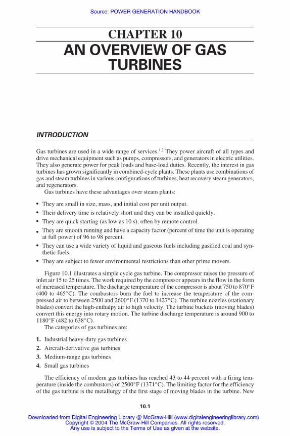
AN OVERVIEW OF GASTURBINES
INTRODUCTION
Gas turbines are used in a wide range of services.1,2 They power aircraft of all types anddrive mechanical equipment such as pumps, compressors, and generators in electric utilities.They also generate power for peak loads and base-load duties. Recently, the interest in gasturbines has grown significantly in combined-cycle plants. These plants use combinations ofgas and steam turbines in various configurations of turbines, heat recovery steam generators,and regenerators.
Gas turbines have these advantages over steam plants:
● They are small in size, mass, and initial cost per unit output.● Their delivery time is relatively short and they can be installed quickly.● They are quick starting (as low as 10 s), often by remote control.
● They are smooth running and have a capacity factor (percent of time the unit is operatingat full power) of 96 to 98 percent.
● They can use a wide variety of liquid and gaseous fuels including gasified coal and syn-thetic fuels.
● They are subject to fewer environmental restrictions than other prime movers.
Figure 10.1 illustrates a simple cycle gas turbine. The compressor raises the pressure ofinlet air 15 to 25 times. The work required by the compressor appears in the flow in the formof increased temperature. The discharge temperature of the compressor is about 750 to 870°F(400 to 465°C). The combustors burn the fuel to increase the temperature of the com-pressed air to between 2500 and 2600°F (1370 to 1427°C). The turbine nozzles (stationaryblades) convert the high-enthalpy air to high velocity. The turbine buckets (moving blades)convert this energy into rotary motion. The turbine discharge temperature is around 900 to1180°F (482 to 638°C).
The categories of gas turbines are:
1. Industrial heavy-duty gas turbines
2. Aircraft-derivative gas turbines
3. Medium-range gas turbines
4. Small gas turbines
The efficiency of modern gas turbines has reached 43 to 44 percent with a firing tem-perature (inside the combustors) of 2500°F (1371°C). The limiting factor for the efficiencyof the gas turbine is the metallurgy of the first stage of moving blades in the turbine. New
CHAPTER 10
10.1
Downloaded from Digital Engineering Library @ McGraw-Hill (www.digitalengineeringlibrary.com)Copyright © 2004 The McGraw-Hill Companies. All rights reserved.
Any use is subject to the Terms of Use as given at the website.
Source: POWER GENERATION HANDBOOK

10.2 CHAPTER TEN
FIGURE 10.1 Combustion turbine, Model CW251B11/12.
The combustion turbine is a single shaft, two-bearing, solid coupling, simple cycle unit containing:
Multistage (19) axial-flow air compressor featuring:
● Variable inlet guide vanes.
● Horizontally split casing giving access to internal parts.
● Individually removable stainless steel blading.
● Accessible pressure-lubricated, pivoted-pad journal bearing.
● Double acting Kingsbury-type thrust bearing.
● Cold-end drive with solid coupling to main reduction gear.
Combustion system including the following:
● Eight can-type combustors in a circular array.
● Combustors removable with cylinder cover in place.
● Optional multiple fuels capability.
● Ignition system with retractable igniters.
Three-stage reaction-type turbine featuring:
● Horizontally split casing giving access to internal parts.
● Alloy turbine blades individually removable.
● Cooled by air-to-air cooler, with cooling air filtered.
● Individual first-stage vanes removable with cylinder cover in place.
● Accessible pressure-lubricated, pivoted-pad journal bearing.
● Low loss axial-exhaust system ideal for waste heat applications.
AN OVERVIEW OF GAS TURBINES
Downloaded from Digital Engineering Library @ McGraw-Hill (www.digitalengineeringlibrary.com)Copyright © 2004 The McGraw-Hill Companies. All rights reserved.
Any use is subject to the Terms of Use as given at the website.

air-cooling methods and breakthroughs in the metallurgy of turbine blades allowed gasturbines available in research laboratories today to operate at 2800 to 3000°F (1538 to1649°C). These gas turbines have higher efficiency than the modern gas turbines used inindustry. Regeneration* has lowered the heat rate.† However, the best heat rate has beenachieved by combining the gas turbine cycle with a steam turbine cycle. The arrangementis called combined cycles. Its heat rate is around 5000 to 7000 Btu/kWh. The efficiency ofa gas turbine is affected by the firing temperature and pressure ratio across the compressor.For every 100°F (56°C) increase in firing temperature, the work output and efficiencyincrease by 10 percent and 1.5 percent, respectively.
Figures 10.2 and 10.3 illustrate a performance map of a simple-cycle and a regenerativecycle gas turbine as a function of pressure ratio and turbine inlet temperature. The pressureratio has the opposite effect in a regenerative cycle compared to that experienced in a simplecycle. Regenerators can increase the efficiency of a modern gas turbine by about 15 to 20percent. The optimum pressure ratio for a modern regenerative system is about 7:1 comparedto 18:1 for a simple cycle gas turbine.
THE BRAYTON CYCLE
The Brayton cycle governs the behavior of gas turbines. Figure 10.4 illustrates an idealBrayton cycle. It has two adiabatic-reversible (isentropic) processes and two constant-pressure processes.
AN OVERVIEW OF GAS TURBINES 10.3
*Regeneration consists of using a heat exchanger that recovers the heat from the air being discharged from theturbine. The temperature of the air discharged from the turbine is around 900 to 1180°F (482 to 638°C).
†The heat rate is the inverse of the efficiency (1/efficiency). It represents the amount of heat consumed (in Btu)to generate 1 kWh.
FIGURE 10.2 Performance map of a simple cycle.
AN OVERVIEW OF GAS TURBINES
Downloaded from Digital Engineering Library @ McGraw-Hill (www.digitalengineeringlibrary.com)Copyright © 2004 The McGraw-Hill Companies. All rights reserved.
Any use is subject to the Terms of Use as given at the website.

The work done in the turbine WT is equal to the rate of change of its enthalpy. Thus,•
WT �•
H3 � •
H4 � •m(h3 � h4) (10.1)
where•
H � total enthalpy of flowing gas, Btu/h or Wh � specific enthalpy, Btu/lbm or J/kg•m � mass rate of flow of gas, lbm/h or kg/s
Figure 10.5 illustrates a simple-cycle, two-shaft gas turbine. The power turbine, alsoknown as the low-pressure turbine, operates on a different shaft than the high-pressureturbine and compressor. This feature allows the power turbine to drive a load at a wide rangeof speeds. Thus, the two-shaft machines are suitable for applications requiring variable speed.
10.4 CHAPTER TEN
FIGURE 10.3 Performance map of a regenerative cycle.
FIGURE 10.4 P-V and T-s diagrams of an ideal Brayton cycle.
AN OVERVIEW OF GAS TURBINES
Downloaded from Digital Engineering Library @ McGraw-Hill (www.digitalengineeringlibrary.com)Copyright © 2004 The McGraw-Hill Companies. All rights reserved.
Any use is subject to the Terms of Use as given at the website.

The portion of the gas turbine consisting of compressors, combustors, and high-pressure(HP) turbine is called the gas generator. All the power developed by the HP turbine is usedto drive the compressors. The requirements for starting this gas turbine are less than theones for a single-shaft gas turbine. The reason is the reduced inertia of the spool carrying thecompressor and HP turbine.
The ideal (isentropic) efficiency and specific work of a gas turbine are given by:
�th � 1 � ; � cp �T1 (1 � rp(k�1)/k � T3 �1 � �� (10.2)
rpT � ; k � ; � rpT(k�1)/k
INDUSTRIAL HEAVY-DUTY GAS TURBINES
Industrial heavy-duty gas turbines entered the market in the early 1950s. These ground-basedunits did not have restrictions on weight and space. Their design characteristics includedheavy-wall casings, sleeve bearings, large-diameter combustors, thick airfoil sections formoving and stationary blades, and large frontal areas. The pressure ratio for these gas turbinesincreased from 5:1 for earlier units to 15 to 25:1 for modern units. The turbine inlet temper-ature for a modern unit is around 2000 to 2500°F (1093 to 1371°C). Projected temperaturesapproach 3000°F (1649°C) and when achieved, would result in a significant increase in theefficiency of these machines. The industrial heavy-duty gas turbines normally use axial-flowcompressors and turbines. In most North American designs, the combustors are can-annularas shown in Figs. 10.6(a) and 10.6(b). European designs use single-stage side combustorsas shown in Fig. 10.7. The combustors of these units normally have heavy walls and arevery durable. The liners are designed to produce low smoke and low NOX* emissions. Most
T3�T4
cp�cv
P3�P4
1�rp
(k�1)/k
•Wn�•m
1�rp
(k�1)/k
AN OVERVIEW OF GAS TURBINES 10.5
FIGURE 10.5 Dual-shaft gas turbine. A: LP compressor; B: HP compressor; C: combustors; D: HP com-pressor turbine; E: LP compressor turbine; F: power turbine; G: bearings.
*NOX is a term used to describe the mixture of NO and NO2.
AN OVERVIEW OF GAS TURBINES
Downloaded from Digital Engineering Library @ McGraw-Hill (www.digitalengineeringlibrary.com)Copyright © 2004 The McGraw-Hill Companies. All rights reserved.
Any use is subject to the Terms of Use as given at the website.

of these units have dual fuel flexibility. The velocity of the inlet air drops in the large frontalareas resulting in a reduction of air noise. The auxiliary equipment includes heavy-dutypumps and motors that have been tested for long hours. Heavy-duty governors are also usedin the control system. Electronic governors are being used in some newer models. The fol-lowing are the advantages of heavy-duty gas turbines:
● High availability● Long life● Slightly higher efficiencies when compared with other types of gas turbines● Significantly lower noise levels than aircraft-type gas turbines
These machines are used normally in electric utilities to deliver base load power.
10.6 CHAPTER TEN
FIGURE 10.6 (a) Can-annular combustor with transition piece. (©Rolls-Royce Limited) (b) A typical diffusionflame, can-annular, reverse-flow combustor. (Courtesy General Electric Company)
AN OVERVIEW OF GAS TURBINES
Downloaded from Digital Engineering Library @ McGraw-Hill (www.digitalengineeringlibrary.com)Copyright © 2004 The McGraw-Hill Companies. All rights reserved.
Any use is subject to the Terms of Use as given at the website.
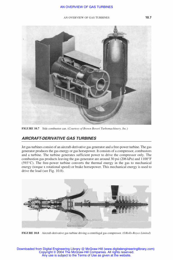
AIRCRAFT-DERIVATIVE GAS TURBINES
Jet gas turbines consist of an aircraft-derivative gas generator and a free-power turbine. The gasgenerator produces the gas energy or gas horsepower. It consists of a compressor, combustorsand a turbine. The turbine generates sufficient power to drive the compressor only. Thecombustion gas products leaving the gas generator are around 30 psi (206 kPa) and 1100°F(593°C). The free-power turbine converts the thermal energy in the gas to mechanicalenergy (torque x rotational speed) or brake horsepower. This mechanical energy is used todrive the load (see Fig. 10.8).
AN OVERVIEW OF GAS TURBINES 10.7
FIGURE 10.7 Side combustor can. (Courtesy of Brown Boveri Turbomachinery, Inc.)
FIGURE 10.8 Aircraft-derivative gas turbine driving a centrifugal gas compressor. (©Rolls-Royce Limited)
AN OVERVIEW OF GAS TURBINES
Downloaded from Digital Engineering Library @ McGraw-Hill (www.digitalengineeringlibrary.com)Copyright © 2004 The McGraw-Hill Companies. All rights reserved.
Any use is subject to the Terms of Use as given at the website.

Aircraft-type turbines are mainly used in the gas transmission industry and as peakingunits in power plants. These are their main benefits:
● Relatively low installation cost● They can easily be operated unattended by remote control due to the following reasons:
● Their auxiliary systems are not complex.● They do not require water cooling (oil-to-air heat exchangers are used for cooling).● Their starting device, which is normally a gas expansion motor, requires little power.● Their performance can be monitored remotely. Maintenance is initiated upon degra-
dation in performance.
MEDIUM-RANGE GAS TURBINES
Medium-range gas turbines are rated between 5000 to 15,000 hp (3.7 to 11.2 MW). Theseunits have relatively high efficiency at part-load operation. The gasifier (section that gen-erates the hot gas) operates at maximum efficiency, while the power turbine operates atvariable speed. The compressor has normally 10 to 16 stages. Its pressure ratio (dischargepressure/inlet pressure) is around 5 to 11. Most American manufacturers use can-annular(5 to 10 combustor cans mounted on a circular ring) or annular-type combustors. Europeanmanufacturers normally use side combustors. The turbine inlet temperature of mostEuropean designs is normally lower than in American counterparts. Most gasifiers use a 2to 3 stage axial turbine. Its first-stage nozzles (stationary blades) and buckets (moving blades)normally are air-cooled. Most power turbines have one or two stages.
These units are normally used on offshore platforms and in petrochemical plants.Regenerators are used with these turbines to improve their efficiency.
SMALL GAS TURBINES
Small gas turbines are rated below 5000 hp (3.7 MW). Their design is similar to the largerturbines discussed earlier. However, they normally use centrifugal compressors or combi-nations of centrifugal and axial compressors and radial-inflow turbines. These units havean efficiency of around 20 percent due to the following reasons:
● Centrifugal compressors have lower efficiency than their axial counterparts.● The turbine inlet temperature is limited to around 1700 °F (927°C) due to lack of blade
cooling.
The efficiency of these units can be improved by recovering the exhaust heat fromthe turbine.
MAJOR GAS TURBINE COMPONENTS
Compressors
Gas turbines use axial and centrifugal compressors. Small gas turbines use centrifugal com-pressors while all the larger ones use axial compressors.
10.8 CHAPTER TEN
AN OVERVIEW OF GAS TURBINES
Downloaded from Digital Engineering Library @ McGraw-Hill (www.digitalengineeringlibrary.com)Copyright © 2004 The McGraw-Hill Companies. All rights reserved.
Any use is subject to the Terms of Use as given at the website.

Axial-Flow Compressors. Axial-flow compressors increase the pressure of the fluid byaccelerating it in the rotating blades and then diffusing* it in the stationary blades. A com-pressor stage consists of one row of stationary blades and one row of moving blades. Anadditional row of fixed blades (inlet guide vanes) is normally installed at the inlet to thecompressor to direct the air at the desired angle to the first-stage of rotating blades. An addi-tional diffuser is installed at the compressor discharge. It diffuses the fluid further beforeentering the combustors. Figure 10.1 shows a 19-stage axial flow compressor. The overallpressure increase across a compressor of a modern gas turbine varies between 20:1 and40:1. These compressors are generally more efficient than centrifugal compressors. Theyare also usually much smaller and run at higher speeds.
Centrifugal Compressors. Figure 10.9 illustrates the impellers of a centrifugal compressor.Air is taken at the center or “eye” of the rotor. It is accelerated by the blades due to highrotational speeds of the rotor and forced radially out of the rotor at high velocities. The airis then received by the diffuser, which converts the high velocity to high pressure.
A single compressor stage consists of an impeller mounted on the rotor and a diffusermounted in the stator. The air enters the compressor at the inducer (see Fig. 10.10). It goesthrough a 90º turn and is discharged into a diffuser which normally has a vaneless spacefollowed by a vaned section. The air leaves the diffuser and enters a scroll or collector.The pressure increase per stage of a centrifugal compressor varies between 1.5:1 and 12:1.Centrifugal compressors have lower efficiency than axial-flow compressors. However,
AN OVERVIEW OF GAS TURBINES 10.9
*A diffuser is a component of increasing cross-sectional area. The fluid pressure increases across it due todecrease in velocity.
FIGURE 10.9 Closed impeller. (Courtesy Elliott Company, Jeannette, PA)
AN OVERVIEW OF GAS TURBINES
Downloaded from Digital Engineering Library @ McGraw-Hill (www.digitalengineeringlibrary.com)Copyright © 2004 The McGraw-Hill Companies. All rights reserved.
Any use is subject to the Terms of Use as given at the website.

they are not as prone to a reduction in efficiency due to the build-up of deposits as in axial-flow compressors. Their main advantages are simplicity, strength, and short length.
Compressor Materials
The compressor casings are usually made of cast iron or aluminum alloy. The rotors areusually made of good-quality ferrite steel, and the compressor blades will be stainless steelor titanium alloys.
Two-Stage Compression
The compression process requires less work if heat is removed from the gas during theprocess. This improves the efficiency of the gas turbine. A two-stage compression is oftenused with an intercooler between the stages (see Fig. 10.11).
10.10 CHAPTER TEN
scroll
vaneddiffuser
vanelessdiffuser
impeller
shroud
inducer
hubintake duct
inlet guide vanefluid
FIGURE 10.10 Schematic of a centrifugal compressor.
FIGURE 10.11 Two-stage compression. A: compressor; B: intercooler; C: compressor.
AN OVERVIEW OF GAS TURBINES
Downloaded from Digital Engineering Library @ McGraw-Hill (www.digitalengineeringlibrary.com)Copyright © 2004 The McGraw-Hill Companies. All rights reserved.
Any use is subject to the Terms of Use as given at the website.

AN OVERVIEW OF GAS TURBINES 10.11
FIGURE 10.12 Gas turbine with regenerator.
Regenerators
In simple gas turbines, the gases exhausted from the turbine are still at a high temperature,900 to 1180°F (482 to 638°C). The thermal efficiency of the gas turbine will improve if someof the heat in the exhaust gases is transferred to the compressed air before the air enters thecombustor. This is accomplished by adding a heat exchanger called a regenerator to the basiccycle (see Fig. 10.12).
The regenerator (see Fig. 10.13) is a shell-and-tube heat exchanger having the turbine exhaust gasesflowing in the tubes or on the shell side. The temper-ature of the exhaust gases from the turbine is reducedto 500°F (260°C) by transferring heat to the air inthe regenerator. The air enters the regenerator at392°F (200°C) and leaves at about 698°F (370°C).The regenerator can recover up to 75 percent of theexhaust heat, resulting in increase in efficiency.
Heavy-duty regenerators are used in large gasturbines in the 5000 to 100,000 hp (3.7 to 74.6 MW)range. They increase the efficiency of the unit byreducing the fuel consumption by up to 30 percent.Despite this increase in efficiency, regenerators areonly used by a small number of manufacturers forthese reasons:
● The increase in efficiency caused by using regenerators decreases steadily as the unit isoperated due to build-up of deposits inside the regenerator.
● Regenerators are only used by turbines having low pressure increase across their com-pressors. The reason for this is that gas turbines having a large pressure increase acrosstheir compressors will also have a large temperature increase across them (the workrequired to increase the pressure across a compressor is proportional to the temperatureincrease across it). Since the temperature of the gas leaving the turbine is around 482°C(900°F), units having large pressure increase across their compressors will have limitedbenefit from a regenerator because the exit temperature of the compressor will approachthe exit temperature of the turbine.
● Regenerators have relatively high cost, space, and maintenance requirements.
FIGURE 10.13 A typical plate-fin indus-trial regenerator for gas turbines.
AN OVERVIEW OF GAS TURBINES
Downloaded from Digital Engineering Library @ McGraw-Hill (www.digitalengineeringlibrary.com)Copyright © 2004 The McGraw-Hill Companies. All rights reserved.
Any use is subject to the Terms of Use as given at the website.

Combustors
The purpose of the combustor is to increase the temperature of the high-pressure gas. Thereis a slight pressure drop across the combustors. The four categories of combustors are:
● Tubular (side combustors)● Can-annular● Annular
Tubular (side combustors). These combustors(see Figs. 10.7 and 10.14) are normally installedon large European industrial turbines. Their advan-tages are:
● Simple design● Ease of maintenance● High longevity
They could be of a “straight-through” or “reverse-flow” design. In the reverse-flow type, air entersthe annulus between the combustor can and thehousing. This design has minimal length.
Can-Annular and Annular. Most indus-trial heavy-duty gas turbines designed in theUnited States use can-annular combustors [see Figs.10.6(a) and (b)]. Can-annular (known also as tubo-annular, Figs. 10.15 and 10.16) and annular (Fig.10.17) combustors are used in aircraft enginesdue to their favorable radial and circumferential
10.12 CHAPTER TEN
FIGURE 10.14 A typical single-can sidecombustor for an industrial turbine. (CourtesyBrown Boveri Turbomachinery, Inc.)
FIGURE 10.15 Tubo-annular or can-annular combustor for a heavy-duty gas turbine. (Courtesy of GeneralElectric Company)
AN OVERVIEW OF GAS TURBINES
Downloaded from Digital Engineering Library @ McGraw-Hill (www.digitalengineeringlibrary.com)Copyright © 2004 The McGraw-Hill Companies. All rights reserved.
Any use is subject to the Terms of Use as given at the website.

profiles. These designs are suited for the large number of fuel nozzles employed in theseapplications. Annular combustors are used more commonly in applications having highertemperatures and low-heat-content (low-Btu) gases.
There are straight-through and reverse-flow can-annular combustors. The can-annular cansused in the aircraft industry are of the straight-through design. The reverse-flow design isnormally used in industrial engines. Annular combustors are normally straight-through design.
Combustor Operation. In multiple-type combustors, there is a fuel supply to each flametube, but there are only a couple of igniters for all the tubes. When ignition occurs in theflame tubes having the igniters, the crossfire tubes takes the hot gases from the hot flame tubeto ignite the remainder. This occurs in a matter of one second. Once the flame detectorsconfirm stable ignition, the igniter will shut down. The manufacturers of gas turbines confirmthat any fuel can be used if the necessary changes are made to the fuel system.
Turbines
Axial-flow and radial-inflow turbines are used in gas turbine applications. However, morethan 80 percent of gas turbines use axial-flow turbines.
AN OVERVIEW OF GAS TURBINES 10.13
FIGURE 10.16 Tubo-annular combustion chamber for aircraft-type gas turbines. (©Rolls-Royce Limited)
AN OVERVIEW OF GAS TURBINES
Downloaded from Digital Engineering Library @ McGraw-Hill (www.digitalengineeringlibrary.com)Copyright © 2004 The McGraw-Hill Companies. All rights reserved.
Any use is subject to the Terms of Use as given at the website.

Axial-Flow Turbines. The flow in an axial-flow turbine (Fig. 10.18) and its counterpart,the axial-flow compressor, enters and leaves in the axial direction. These turbines can be ofthe impulse type or the reaction type. In an impulse turbine, the enthalpy drops entirely (theenergy available in the high temperature and pressure is converted into velocity) in the nozzles(stationary blades). Thus, the velocity of the gas entering the rotor is very high. In a reactionturbine, the enthalpy drops in the nozzles and the buckets (moving blades).
Radial-Inflow Turbine. The radial-inflow turbine, or inward-flow radial turbine, consistsof a centrifugal compressor having reverse flow and opposite rotation. These turbines areused for smaller loads and over a narrower operating range than the axial turbine. Axial tur-bines are normally suited for aircraft and power generation applications. However, they aremuch longer than radial turbines. This makes them unsuitable for certain applications.Radial turbines are normally used for turbochargers and in some types of expanders.
10.14 CHAPTER TEN
FIGURE 10.17 Annular Combustion Chamber. (©Rolls-Royce Limited.)
AN OVERVIEW OF GAS TURBINES
Downloaded from Digital Engineering Library @ McGraw-Hill (www.digitalengineeringlibrary.com)Copyright © 2004 The McGraw-Hill Companies. All rights reserved.
Any use is subject to the Terms of Use as given at the website.

Heat Recovery Steam Generators
Most of the heat available in the exhaust gases [normally around 482 to 638°C (900 to1180°F)] of a gas turbine can be recaptured in a heat recovery steam generator (HRSG).The steam can be used in the following applications:
● To drive a steam turbine in a combined cycle* plant● For heating purposes in a cogeneration plant● For a process in an industry such as a petrochemical plant
The HRSG (Fig. 10.19) is a counterflow heat exchanger used to generate steam byconvection.
The following are its main components:
● The superheater: This is the first component exposed to the exhaust gases from the gasturbine. It superheats the saturated steam leaving the boiler.
AN OVERVIEW OF GAS TURBINES 10.15
FIGURE 10.18 Schematic of an axial-flow turbine. (Courtesy of Westinghouse Electric Corporation.)
*A combined cycle consists of a gas turbine working in conjunction with a steam power plant through an HRSG.
FIGURE 10.19 Supplementary fired exhaust gas steam generator. (Courtesy of Henry Vogt Machine Company.)
AN OVERVIEW OF GAS TURBINES
Downloaded from Digital Engineering Library @ McGraw-Hill (www.digitalengineeringlibrary.com)Copyright © 2004 The McGraw-Hill Companies. All rights reserved.
Any use is subject to the Terms of Use as given at the website.

● The boiler: This component is exposed to the hot gases leaving the superheater. It providesthe latent heat required to evaporate the saturated water leaving the economizer.
● The economizer: This component is exposed to the hot gases leaving the boiler. It providesthe heat required to raise the temperature of the subcooled water entering the HRSGto saturation.
TOTAL ENERGY ARRANGEMENT
Gas turbines have been used in cogeneration and combined cycles plants to produce elec-tricity and steam. In some cases, the steam is used in absorption chillers to produce cold water,which is used for cooling buildings with the aid of a cooling tower. This is known as a totalenergy arrangement due to the generation of steam, electricity, and cold water.
GAS TURBINE APPLICATIONS
Gas turbines have been used to produce power as well as an engine to drive pumps, com-pressors, emergency equipment, etc. It is common to use gas turbines in power plants andhospitals to produce instant emergency power for essential services when the main powersupply is interrupted. Gas turbines are ideal for use as an unmanned and remotely controlledunit that can be started by a telephone or radio link.
COMPARISON OF GAS TURBINES WITH OTHERPRIME MOVERS
Modern gas turbines compare very favorably with other machines on the grounds of fuelconsumption, efficiency, and power/mass/size ratios. Gasoline engines operating on theOtto cycle have efficiencies of 20 to 25 percent. The diesel and Rankine cycles (steamplant) have an efficiency of 30 to 35 percent. The modern gas turbine, which operates onthe Brayton cycle, has an efficiency of 44 percent.
REFERENCES
1. Boyce, Meheran P., Gas Turbine Engineering Handbook, Golf Publishing Company, Houston,Tex., 1995.
2. El-Wakil, M. M., Power Plant Technology, McGraw-Hill, New York, 1984.
10.16 CHAPTER TEN
AN OVERVIEW OF GAS TURBINES
Downloaded from Digital Engineering Library @ McGraw-Hill (www.digitalengineeringlibrary.com)Copyright © 2004 The McGraw-Hill Companies. All rights reserved.
Any use is subject to the Terms of Use as given at the website.

GAS TURBINE COMPRESSORS
CENTRIFUGAL COMPRESSORS
When compared with axial compressors, centrifugal compressors have the following fiveadvantages:
1. They occupy a smaller length than the equivalent axial compressors.
2. They are not liable to loss of performance by buildup of deposits on the surfaces of theair channel when working in a contaminated atmosphere.
3. They are able to operate efficiently over a wider range of mass flow at any particularrotational speed (i.e., they alleviate problems of matching operational conditions withthose of the associated turbine).
4. They are used mainly in small power units because the higher isentropic efficiency ofaxial compressors cannot be maintained for small machines.
5. Titanium is the preferable material because of its high resistance to corrosion.
Principle of Operation
The centrifugal compressor consists of a stationary casing containing a rotating impeller,which increases the velocity of the air, and a number of diffusers that decelerate the air con-verting a part of its kinetic energy to pressure. Figure 11.1 illustrates a centrifugal compressor.
Compressor Characteristics
Figure 11.2 illustrates the variation in the pressure ratio when a valve placed in the deliveryline of the compressor running at constant speed is slowly opened. When the valve is shutand the flow is zero, the pressure ratio will have a value A. This is the pressure head that isproduced by the action of the impeller on the air trapped between the vanes. As the valveis opened and the flow increases, the maximum efficiency is reached at point B. Any furtherincrease in flow will result in a decrease of the pressure ratio. If the flow is increased signif-icantly beyond the design flow, the efficiency decreases rapidly. A hypothetical case isreached at point C where the pressure ratio drops to unity (i.e., all the power absorbed bythe compressor is dissipated in friction losses). In reality, point A could be obtained ifdesired. However, most of the curve between points A and B could not be obtained due tothe phenomenon of surging. Surging is associated with a sudden drop in delivery pressure,and with violent aerodynamic pulsations that are transmitted throughout the machine.Assume that the compressor is operating at some point D. A decrease in mass flow shouldbe accompanied by a fall of delivery pressure. If the pressure of the air downstream of the
CHAPTER 11
11.1
Downloaded from Digital Engineering Library @ McGraw-Hill (www.digitalengineeringlibrary.com)Copyright © 2004 The McGraw-Hill Companies. All rights reserved.
Any use is subject to the Terms of Use as given at the website.
Source: POWER GENERATION HANDBOOK

compressor does not fall quickly enough, the air will flow backward due to the pressuregradient. This results in a rapid drop in pressure ratio. The pressure downstream of the com-pressor drops as well until the compressor reestablishes the flow. The surging of the air maynot happen immediately as the operating point moves to the left of point B in Fig. 11.2. Thisis because the pressure downstream of the compressor may fall at a greater rate than thedelivery pressure. As the mass flow is reduced, the flow reversal will occur. The conditionsbetween points A and B are inherently unstable. If the operating point is on the part on thecurve having negative slope, a decrease in mass flow results in increase in delivery pressure.The flow characteristic in this region is stable.
In a gas turbine, the swallowing capacity of the components downstream of the com-pressor (e.g., the turbine) and the way the swallowing capacity varies over the range ofoperating conditions determines the actual point at which surging occurs. An additionallimitation exists in the operating range between points B and C. As the mass flow increasesand the pressure decreases, the density is reduced and the radial component of velocitymust increase (m � �AV). Point E is reached where no further increase in mass flow can be
11.2 CHAPTER ELEVEN
FIGURE 11.1 Diagrammatic sketches of centrifugal compressors. (a) Impeller and diffuser of a centrifugalcompressor; (b) impeller of a centrifugal compressor; (c) different compeller of a centrifugal compressor;(d) impeller shroud.
GAS TURBINE COMPRESSORS
Downloaded from Digital Engineering Library @ McGraw-Hill (www.digitalengineeringlibrary.com)Copyright © 2004 The McGraw-Hill Companies. All rights reserved.
Any use is subject to the Terms of Use as given at the website.

obtained and choking occurs. This point represents the maximum flow obtainable at theparticular rotational speed. Other curves can be obtained for different speeds.
Figure 11.3 (a) illustrates the actual variation of pressure ratio over the complete rangeof mass flow and rotational speed. The left-hand extremities of the constant-speed curvesare joined up to form what is known as the surge line. The right-hand extremities representthe points where choking occurs.
Since the isentropic p-T relation is given by:
T2/T1 � r(��1)/� � T3/T4
where r is the pressure ratio P2/P1 � r � P3/P4.Therefore, the form of the curves of the temperature ratio plotted on the same basis will
be similar to the pressure ratio plotted in Fig. 11.3 (a). The isentropic efficiency curves areplotted in Fig. 11.3 (b). The efficiency varies with the mass flow at a given speed in a similarmanner to the pressure ratio. However, the maximum value for all speeds is approximatelythe same. A curve representing the locus of operating points at maximum efficiency is shownin Fig. 11.3 (a). Gas turbines are usually designed to operate on this curve.
AXIAL-FLOW COMPRESSORS
The performance of axial-flow compressors exceeds that of the centrifugal compressors.Axial-flow compressors are used in the greater proportion of gas turbines of all applications.This type of compressor is described as “the reversed multistage axial flow turbine.” In axialcompressors, the flow is decelerating or diffusing by causing the fluid to pass through aseries of expanding passages where the pressure rise is obtained by reduction in velocity.For good performance, the blades of the compressor rotor form series of diverging passages.In the case of a turbine, the passages are converging. Figure 11.4 illustrates the fundamentaldifferences between the two types. Stalling troubles are prevalent in axial-flow compressors.Stalling occurs when the relevant angle of incidence between the flow direction and the
GAS TURBINE COMPRESSORS 11.3
FIGURE 11.2 Theoretical characteristic.
GAS TURBINE COMPRESSORS
Downloaded from Digital Engineering Library @ McGraw-Hill (www.digitalengineeringlibrary.com)Copyright © 2004 The McGraw-Hill Companies. All rights reserved.
Any use is subject to the Terms of Use as given at the website.

11.4 CHAPTER ELEVEN
FIGURE 11.3 Centrifugal compressor characteristics. (a) Variation of pressure ratio in acentrifugal compressor; (b) variation of isentropic efficiency in a centrifugal compressor.
GAS TURBINE COMPRESSORS
Downloaded from Digital Engineering Library @ McGraw-Hill (www.digitalengineeringlibrary.com)Copyright © 2004 The McGraw-Hill Companies. All rights reserved.
Any use is subject to the Terms of Use as given at the website.

blades becomes excessive. Since the pressure gradient is acting against the direction of theflow, there is always danger to the stability of the flow pattern. Breakdown can easily occurat conditions of mass flow and rotational speed that are different from the ones for whichthe blades were designed.
The axial-flow compressor has two main components: (1) the rotor and (2) the stator.The rotor carries the moving blades and the stator the stationary rows. The stationary rowsconvert the kinetic energy imparted to the working fluid by the rotor blades to pressureincrease. Also, the stationary rows redirect the flow into an angle that is suitable for entryto the next row of moving blades. Each stage consists of a stationary row followed by arotating row. A row of inlet guide vanes is usually provided to the stator upstream of thefirst stage. They direct the flow correctly into the first row of rotating blades. The charac-teristic curves of an axial-flow compressor are similar to those of a centrifugal compressor.Figure 11.5 illustrates the axial compressor flow characteristics.
Blowoff valves are used sometimes to prevent surging when it is expected to occur nearthe rear of the compressor. Air is discharged from the compressor at some intermediatestage through a valve to reduce the mass flow through the later stages. Figure 11.6 illus-trates the effects of the blowoff valve on the compressor characteristics. Figure 11.7 illustratesthe effect of the blowoff valve and increased nozzle area on the compressor character-istics. A twin-spool compressor is another technique used to prevent surging by splittingthe compressor into two (or more) sections, each being driven by a separate turbine at adifferent speed.
Figure 11.8 illustrates the effects of acceleration and deceleration on the compressorcharacteristics. Smooth starting and part load control therefore require devices such as variable
GAS TURBINE COMPRESSORS 11.5
FIGURE 11.4 Comparison of typical forms of turbine and com-pressor rotor blades.
GAS TURBINE COMPRESSORS
Downloaded from Digital Engineering Library @ McGraw-Hill (www.digitalengineeringlibrary.com)Copyright © 2004 The McGraw-Hill Companies. All rights reserved.
Any use is subject to the Terms of Use as given at the website.

11.6 CHAPTER ELEVEN
FIGURE 11.5 Axial-flow compressor characteristics. (a) Variation of pressure ratio in anaxial flow compressor; (b) variation of isentropic efficiency in an axial flow compressor.
GAS TURBINE COMPRESSORS
Downloaded from Digital Engineering Library @ McGraw-Hill (www.digitalengineeringlibrary.com)Copyright © 2004 The McGraw-Hill Companies. All rights reserved.
Any use is subject to the Terms of Use as given at the website.

GAS TURBINE COMPRESSORS 11.7
FIGURE 11.6 Typical gas turbine compressor characteristic. The basis of gas turbine design and enginegoverning requirements.
FIGURE 11.7 Effect of blow-off and increased nozzle area.
GAS TURBINE COMPRESSORS
Downloaded from Digital Engineering Library @ McGraw-Hill (www.digitalengineeringlibrary.com)Copyright © 2004 The McGraw-Hill Companies. All rights reserved.
Any use is subject to the Terms of Use as given at the website.

11.8
FIGURE 11.8 Transient trajectories on compressor characteristics (two-shaft machine). Accelerationmoves the operating line toward surge. Deceleration moves the operating line away from surge.
FIGURE 11.9 Axial-flow compressor construction. (a) Variable stator vanes; (b) bleed or dump valves.
GAS TURBINE COMPRESSORS
Downloaded from Digital Engineering Library @ McGraw-Hill (www.digitalengineeringlibrary.com)Copyright © 2004 The McGraw-Hill Companies. All rights reserved.
Any use is subject to the Terms of Use as given at the website.

GAS TURBINE COMPRESSORS 11.9
inlet guide vanes (VIGVs), variable stator vanes (VSVs), or variable controlled bleed ordump valves (VBVs). All these devices avoid surge. They are illustrated in Fig. 11.9.
NOMENCLATURE
These are the most widely used symbols in this chapter.
m � mass flow
r � pressure ratio
�c � isentropic efficiency
� � density
� � ratio of specific heats
A � cross-sectional area
P � absolute pressure
N � speed of rotation
T � absolute temperature
V � flow velocity
Suffixes
0 � stagnation value
1, 2, 3, etc. � reference planes
GAS TURBINE COMPRESSORS
Downloaded from Digital Engineering Library @ McGraw-Hill (www.digitalengineeringlibrary.com)Copyright © 2004 The McGraw-Hill Companies. All rights reserved.
Any use is subject to the Terms of Use as given at the website.

GAS TURBINE COMPRESSORS
Downloaded from Digital Engineering Library @ McGraw-Hill (www.digitalengineeringlibrary.com)Copyright © 2004 The McGraw-Hill Companies. All rights reserved.
Any use is subject to the Terms of Use as given at the website.