Embed Size (px)
DESCRIPTION
TDI-CIS 扫描 MTF 模型. 李林 2013.6. CONTENT. Introduction Principle of TDI-CIS Scanning MTF model of TDI-CIS Simulation and verification. - PowerPoint PPT Presentation
Citation preview
TDI-CIS扫描MTF模型
李林2013.6.
CONTENT
IntroductionPrinciple of TDI-CIS Scanning MTF model of TDI-CIS Simulation and verification

Time-delay-integration (TDI) is a particular scanning imaging mode which can implement exposure repeatedly for the same scene. It prolongs exposure time equivalently so as to improve signal-noise ratio and sensitivity.The TDI principle has been widely used with CCD sensors which can intrinsically shift the charge signal along the CCD scanning direction synchronously with the moving CCD sensor. Besides, implementation of the addition process in CCD is noise free. TDI addressed with CMOS has potential advantages, such as low power consumption, process accessibility, high radiation hardness, etc. However, addition process without noise is not easily implemented in CMOS. In particular, it is not possible to follow the image movement on pixel plane by synchronously shifting signal during integration, potentially resulting in image quality degradation.
Modulation transfer function (MTF) shows the relationship between image contrast and spatial frequency when sensor collects images. At the same time, MTF is also used for evaluating the quality of the sensor’s performance. For scanning image system, MTF can be separated in the two orthogonal directions. The MTF along the scanning direction is more easily affected during the imaging process and make a big difference on the image quality. As a result, it is more practical and valuable to discuss the MTF along the scanning direction.
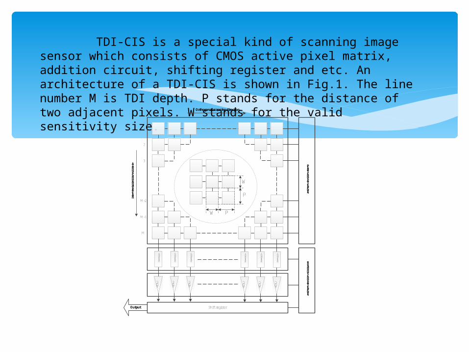
TDI-CIS is a special kind of scanning image sensor which consists of CMOS active pixel matrix, addition circuit, shifting register and etc. An architecture of a TDI-CIS is shown in Fig.1. The line number M is TDI depth. P stands for the distance of two adjacent pixels. W stands for the valid sensitivity size.
1
M-2
Along scanning direction
Pixel control circuit
2
W
P
PW
ADC
Addition
ADC
Addition
ADC
Addition
ADC
Addition
ADC
Addition
ADC
Addition
Shift register
Readout control circuit
Orthogonal scanning direction
Output
3
M-1
M

The timing principle of TDI-CIS which uses rolling-shutter readout with 4 pixels in a column is shown in Fig.2.
TP
1
2
3
Time
TL
Pixel1
Pixel2
Pixel3
TI
Pixel4
TR
4
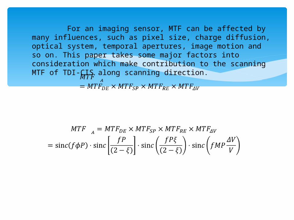
For an imaging sensor, MTF can be affected by many influences, such as pixel size, charge diffusion, optical system, temporal apertures, image motion and so on. This paper takes some major factors into consideration which make contribution to the scanning MTF of TDI-CIS along scanning direction.
0.0 0.1 0.2 0.3 0.4 0.5 0.6 0.7 0.8 0.9 1.00.0
0.1
0.2
0.3
0.4
0.5
0.6
0.7
0.8
0.9
1.0
M
TF
A
f/fN
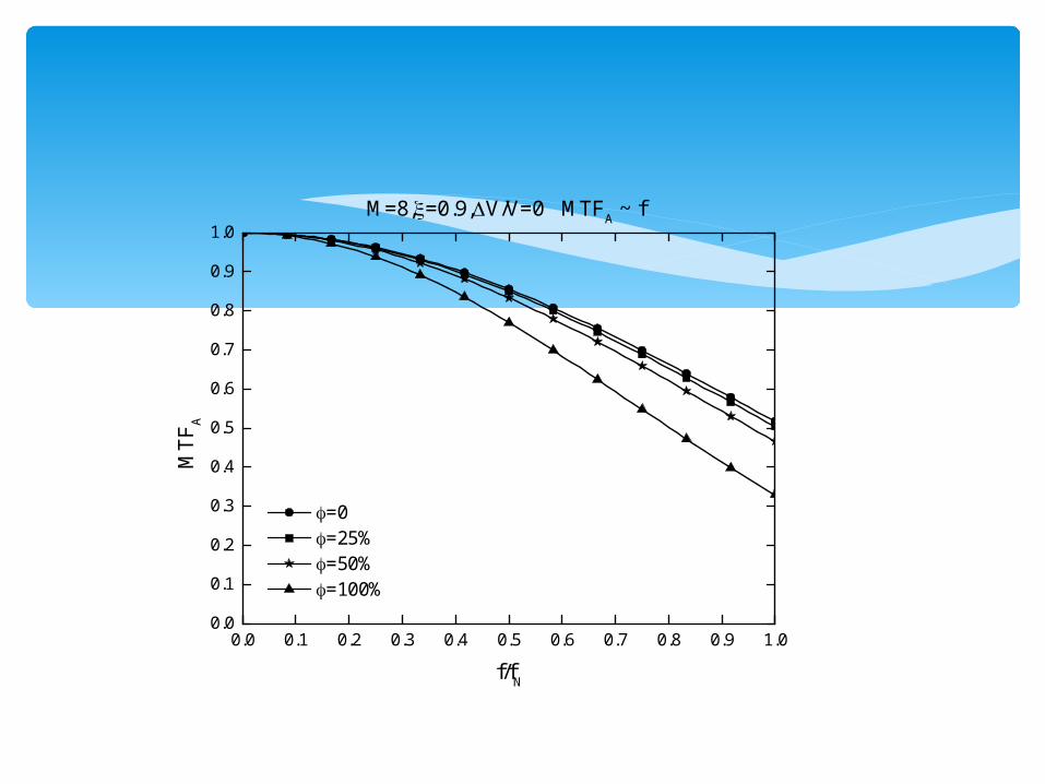
=0 =25% =50% =100%
M=8,=0.9,V/V=0 MTFA ~ f

0.0 0.1 0.2 0.3 0.4 0.5 0.6 0.7 0.8 0.9 1.00.0
0.1
0.2
0.3
0.4
0.5
0.6
0.7
0.8
0.9
1.0
M
TF
A
f/fN
=75% =85% =100%
M=4,=0.5,V/V=0 MTFA ~ f
0.0 0.1 0.2 0.3 0.4 0.5 0.6 0.7 0.8 0.9 1.00.0
0.1
0.2
0.3
0.4
0.5
0.6
0.7
0.8
0.9
1.0
M
TF
A
f/fN
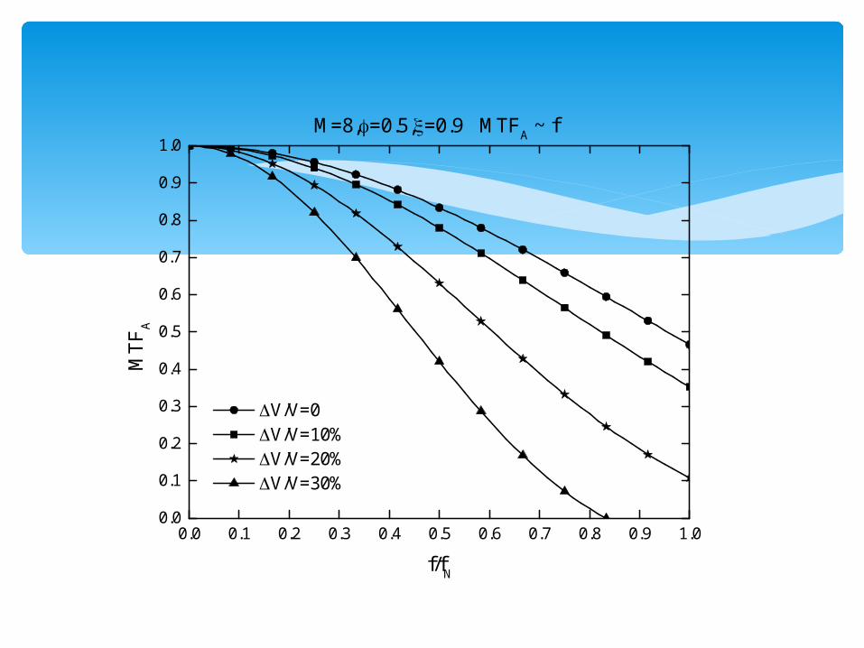
V/V=0 V/V=10% V/V=20% V/V=30%
M=8,=0.5,=0.9 MTFA ~ f
1 2 3 4 5 6 7 8 9 10 11 12 13 14 15 160.00
0.05
0.10
0.15
0.20
0.25
0.30
0.35
0.40
0.45
0.50
M
TF
A
M
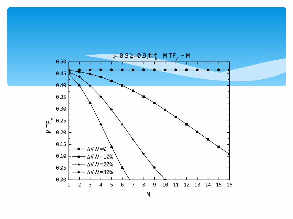
V/V=0 V/V=10% V/V=20% V/V=30%
=0.5,=0.9,f=fN MTF
A ~ M

For verifying the proposed scanning MTF model, a TDI-CIS simulation imaging model according to geometric perspective and light transmission relationship from continuous known objects to a discrete image on the TDI-CIS has been established with MATLAB. The principle of TDI-CIS simulation imaging model is shown in Fig.7. A large resolution grayscale picture is used to simulate the target ground. Gray value of each pixel represents illumination intensity of target ground. Sub-pixel sampling method has been utilized to simulate exposure process of TDI-CIS. Pixel output on TDI-CIS pixel array is equivalent to the integration for those pixels’ gray value of corresponding position on target ground.
(0,0) (length, 0)
(0,width) (length,width)
Target ground
V(pixels/s)
TDI-CIS
Lens
PstartPend
p
Target ground
p
exposure
V
Pend Pstart
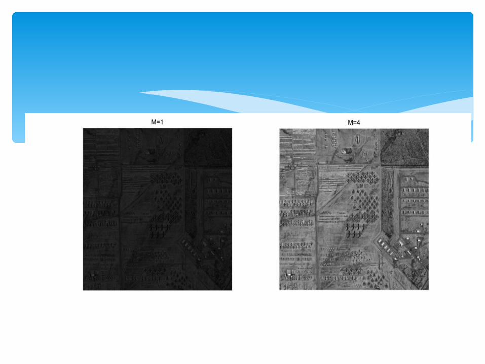
The MTF model indicates that the scanning MTF along scanning direction decreases with increases of pixel valid sensitivity ratio and scanning efficiency. At the same time, the scanning MTF degrades with bigger velocity mismatch ratio and TDI stage number. A TDI-CIS simulation imaging model has been established for verifying the proposed MTF model. The scanning MTF model is verified by the simulation results.