Embed Size (px)
Citation preview

3GPP TR 36.827 V11.0.0 (2012-03)Technical Report
3rd Generation Partnership Project;Technical Specification Group Radio Access Network;Evolved Universal Terrestrial Radio Access (E-UTRA);
LTE Advanced Carrier Aggregation Band 41(Release 11)
The present document has been developed within the 3rd Generation Partnership Project (3GPP TM) and may be further elaborated for the purposes of 3GPP. The present document has not been subject to any approval process by the 3GPP Organizational Partners and shall not be implemented. This Report is provided for future development work within 3GPP only. The Organizational Partners accept no liability for any use of this Specification. Specifications and Reports for implementation of the 3GPP TM system should be obtained via the 3GPP Organizational Partners' Publications Offices.

3GPP
3GPP TR 36.827 V11.0.0 (2012-03)2Release 11
Keywords LTE, Radio
3GPP
Postal address
3GPP support office address 650 Route des Lucioles - Sophia Antipolis
Valbonne - FRANCE Tel.: +33 4 92 94 42 00 Fax: +33 4 93 65 47 16
Internet http://www.3gpp.org
Copyright Notification
No part may be reproduced except as authorized by written permission. The copyright and the foregoing restriction extend to reproduction in all media.
© 2012, 3GPP Organizational Partners (ARIB, ATIS, CCSA, ETSI, TTA, TTC).
All rights reserved. UMTS™ is a Trade Mark of ETSI registered for the benefit of its members 3GPP™ is a Trade Mark of ETSI registered for the benefit of its Members and of the 3GPP Organizational Partners LTE™ is a Trade Mark of ETSI registered for the benefit of its Members and of the 3GPP Organizational Partners GSM® and the GSM logo are registered and owned by the GSM Association
3GPP
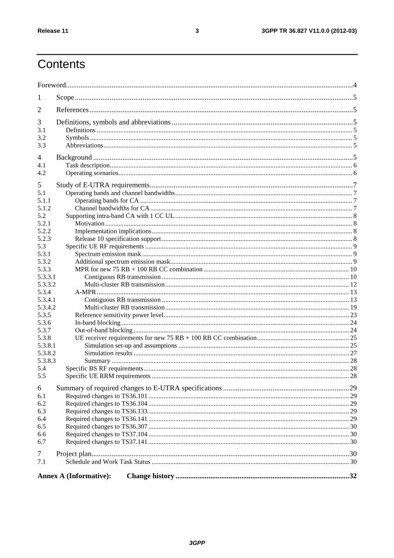
3GPP TR 36.827 V11.0.0 (2012-03)3Release 11
Contents Foreword............................................................................................................................................................. 4 1 Scope ........................................................................................................................................................ 5 2 References ................................................................................................................................................ 5 3 Definitions, symbols and abbreviations ................................................................................................... 5 3.1 Definitions ......................................................................................................................................................... 5 3.2 Symbols ............................................................................................................................................................. 5 3.3 Abbreviations ..................................................................................................................................................... 5 4 Background .............................................................................................................................................. 5 4.1 Task description ................................................................................................................................................. 6 4.2 Operating scenarios............................................................................................................................................ 6 5 Study of E-UTRA requirements ............................................................................................................... 7 5.1 Operating bands and channel bandwidths .......................................................................................................... 7 5.1.1 Operating bands for CA ............................................................................................................................... 7 5.1.2 Channel bandwidths for CA ......................................................................................................................... 7 5.2 Supporting intra-band CA with 1 CC UL .......................................................................................................... 8 5.2.1 Motivation .................................................................................................................................................... 8 5.2.2 Implementation implications ........................................................................................................................ 8 5.2.3 Release 10 specification support .................................................................................................................. 8 5.3 Specific UE RF requirements ............................................................................................................................ 9 5.3.1 Spectrum emission mask .............................................................................................................................. 9 5.3.2 Additional spectrum emission mask ............................................................................................................. 9 5.3.3 MPR for new 75 RB + 100 RB CC combination ....................................................................................... 10 5.3.3.1 Contiguous RB transmission ................................................................................................................ 10 5.3.3.2 Multi-cluster RB transmission .............................................................................................................. 12 5.3.4 A-MPR ....................................................................................................................................................... 13 5.3.4.1 Contiguous RB transmission ................................................................................................................ 13 5.3.4.2 Multi-cluster RB transmission .............................................................................................................. 19 5.3.5 Reference sensitivity power level ............................................................................................................... 23 5.3.6 In-band blocking ........................................................................................................................................ 24 5.3.7 Out-of-band blocking ................................................................................................................................. 24 5.3.8 UE receiver requirements for new 75 RB + 100 RB CC combination ....................................................... 25 5.3.8.1 Simulation set-up and assumptions ...................................................................................................... 25 5.3.8.2 Simulation results ................................................................................................................................. 27 5.3.8.3 Summary .............................................................................................................................................. 28 5.4 Specific BS RF requirements ........................................................................................................................... 28 5.5 Specific UE RRM requirements ...................................................................................................................... 28 6 Summary of required changes to E-UTRA specifications ..................................................................... 29 6.1 Required changes to TS36.101 ........................................................................................................................ 29 6.2 Required changes to TS36.104 ........................................................................................................................ 29 6.3 Required changes to TS36.133 ........................................................................................................................ 29 6.4 Required changes to TS36.141 ........................................................................................................................ 29 6.5 Required changes to TS36.307 ........................................................................................................................ 30 6.6 Required changes to TS37.104 ........................................................................................................................ 30 6.7 Required changes to TS37.141 ........................................................................................................................ 30 7 Project plan ............................................................................................................................................. 30 7.1 Schedule and Work Task Status ...................................................................................................................... 30
Annex A (Informative): Change history ............................................................................................... 32

3GPP
3GPP TR 36.827 V11.0.0 (2012-03)4Release 11
Foreword This Technical Report has been produced by the 3rd Generation Partnership Project (3GPP).
The contents of the present document are subject to continuing work within the TSG and may change following formal TSG approval. Should the TSG modify the contents of the present document, it will be re-released by the TSG with an identifying change of release date and an increase in version number as follows:
Version x.y.z
where:
x the first digit:
1 presented to TSG for information;
2 presented to TSG for approval;
3 or greater indicates TSG approved document under change control.
y the second digit is incremented for all changes of substance, i.e. technical enhancements, corrections, updates, etc.
z the third digit is incremented when editorial only changes have been incorporated in the document.
3GPP
3GPP TR 36.827 V11.0.0 (2012-03)5Release 11
1 Scope The present document is a technical report of the LTE Advanced Carrier Aggregation in Band 41 work item which was approved at TSG RAN #52 [2]. The objective of this work item is to provide specification support for intra-band contiguous carrier aggregation in LTE TDD Band 41.
The report provides motivation, requirements and a list of recommended changes to the specifications.
2 References The following documents contain provisions which, through reference in this text, constitute provisions of the present document.
- References are either specific (identified by date of publication, edition number, version number, etc.) or non-specific.
- For a specific reference, subsequent revisions do not apply.
- For a non-specific reference, the latest version applies. In the case of a reference to a 3GPP document (including a GSM document), a non-specific reference implicitly refers to the latest version of that document in the same Release as the present document.
[1] 3GPP TR 21.905: "Vocabulary for 3GPP Specifications".
[2] RP-110673, “LTE Advanced Carrier Aggregation in Band 41”.
[3] TR36.812 v10.1.0, “Evolved Universal Terrestrial Radio Access (E-UTRA); LTE TDD 2600MHz in US work item Technical Report”
3 Definitions, symbols and abbreviations
3.1 Definitions For the purposes of the present document, the terms and definitions given in TR 21.905 [1] and the following apply. A term defined in the present document takes precedence over the definition of the same term, if any, in TR 21.905 [1].
3.2 Symbols For the purposes of the present document, the following symbols apply:
3.3 Abbreviations For the purposes of the present document, the abbreviations given in TR 21.905 [1] and the following apply. An abbreviation defined in the present document takes precedence over the definition of the same abbreviation, if any, in TR 21.905 [1].
4 Background In the US, up to 194MHz is available for deployment of Band 41 based LTE TDD, with often large contiguous (40MHz+) blocks of channels available. Further details on the specific channel and frequency block arrangement of this band, including the regulatory requirements, are provided in [3].

3GPP
3GPP TR 36.827 V11.0.0 (2012-03)6Release 11
Many network equipment vendors are supporting, or planning to support, dual carrier, 2x 20MHz TDD radios in the near future for the 2600MHz band.
Due to the spectrum and network equipment availability, Band 41 is a prime candidate for deployment of Release 10 based LTE-advanced carrier aggregation capable UEs.
This work item was initiated so that RAN4 could work on developing specification support for contiguous, intra-band carrier aggregation for Band 41 to support deployment of LTE-advanced, building on the initial generic LTE TDD CA work that is developing the framework for TDD intra-band carrier aggregation based on Band 40.
4.1 Task description The purpose of this WI is:
a. Building on the LTE intra-band CA work completed for Band 40, specify the core RF requirements for contiguous intra-band CA in Band 41, specifically considering aggregation of appropriate channel bandwidths up to:
i. 60MHz at the eNB;
ii. 40MHz at the UE with a maximum of 2 CCs on the DL and 1 or 2 CCs on the UL
b. Specify band specific RRM requirements
c. Study specific signalling support requirements in RAN2
d. Add the performance requirements for intra-band carrier aggregation for Band 41 in the relevant specifications
Conformance testing aspects will be covered as part of a separate RAN5 WI.
4.2 Operating scenarios Due to the way the EBS/BRS spectrum band is arranged in the USA [3], aggregated channel bandwidths on the eNB side could comprise the scenarios shown in Table 4.2-1.
Table 4.2-1. Likely carrier aggregation scenarios at the eNB in the EBS/BRS band
Aggregated channels
Aggregated BW
eNB Component Carrier Config
Comment
BRS2-H3 55.5MHz 20+20+15 (55MHz total) All BRS (commercial) channels in the UBS Two blocks 33MHz 20+10 (30MHz total) OR
15+15 (30MHz total) All A & B channels; all B & C channels etc
Three blocks 49.5MHz 15+15+15 (45MHz total) OR 20+15+15 (50MHz total) OR 20+20+10 (50MHz total)
Can fit 20+15+15 / 20+20+10 into 49.5MHz using channel spacing less than nominal Error! Reference source not found.Error! Reference source not found.
Four blocks 66MHz 20+20+20 (60MHz total) All MBS 42MHz 20+20MHz (40MHz total)
As it is proposed to study up to 60MHz at the eNB, all of these scenarios would be in scope. At the eNB side each DL component carrier will have a corresponding UL component carrier making the aggregated BW symmetric between the DL and UL at the eNB.
From the UE perspective, for an eNB operating three component carriers, the UE would only ever be aggregated on up to two adjacent carriers. According to Table 4.2-1, support for the following component carrier aggregation scenarios would therefore be required at the UE:
● 20+20MHz (40MHz)
● 15+15MHz (30MHz)
● 20+10MHz (30MHz)

3GPP
3GPP TR 36.827 V11.0.0 (2012-03)7Release 11
● 20+15MHz (35MHz)
In summary, Band 41 CA capable UEs should ideally be able to support aggregated channel bandwidths of 30, 35 and 40MHz.
At this time it is not proposed to further study support for 5MHz component carriers in carrier aggregation scenarios, or aggregation scenarios that result in aggregated channel bandwidths other than 30, 35 or 40MHz.
5 Study of E-UTRA requirements
5.1 Operating bands and channel bandwidths
5.1.1 Operating bands for CA E-UTRA CA for Band 41 is defined to operate in the entire Band 41 range, as defined in Table 5.1.1-1.
Table 5.1.1-1 Intra band CA operating band definition for Band 41
E-UTRA CA Band
E-UTRA Band
Uplink (UL) operating band Downlink (DL) operating band Duplex Mode BS receive / UE transmit BS transmit / UE receive
FUL_low – FUL_high FUL_low – FUL_high CA_41 41 2496 MHz – 2690 MHz 2496 MHz – 2690 MHz TDD
5.1.2 Channel bandwidths for CA Table 5.1.2-1 defines the supported E-UTRA bandwidths for intra-band contiguous CA in Band 41. As shown, only 10, 15 and 20 MHz component carrier channel bandwidths are proposed to be supported in Band 41 carrier aggregation.
On the UE side, only CA bandwidth class “C” is supported with a maximum number of CCs for combination being two, enabling aggregated bandwidths of 30 and 40 MHz at the UE using symmetric CC BW configurations.
Table 5.1.2-1: Supported E-UTRA bandwidths for intra-band contiguous CA in Band 41
CA operating band / channel bandwidth
E-UTRA CA Band
E-UTRA Bands
1.4 MHz 3 MHz 5 MHz 10 MHz 15 MHz 20 MHz
CA_41C1 41 Yes Yes Yes Note 1: Combinations of component carriers with unequal channel bandwidth should be considered. The
maximum number of CCs for combination is two.
As defined for Band 40, combinations of component carriers with unequal channel bandwidth should be considered for Band 41, specifically combinations of 20 + 10 MHz and 20 + 15 MHz. Subclause 4.2 provides detail on operating scenarios where such configurations may be required and it is proposed to study if these CA combinations can be supported by the intra-band contiguous CA framework developed in Rel-10 for TDD, in the form of Band 40 CA, without significant changes.
It is also proposed to study if it is needed and beneficial to support the case of a UE capable of 2 CC on the DL and 1 CC on the UL, based on the discussion in subclause 4.2.
While eNB CA specifications have been developed to be aggregated bandwidth independent, it is worth noting that aggregation of up to 60MHz is considered to be supported at the eNB side with the downlink and uplink aggregated bandwidth always being symmetric. This enables the eNB to use any two adjacent component carriers for aggregating resources for allocation to a UE.
3GPP
3GPP TR 36.827 V11.0.0 (2012-03)8Release 11
5.2 Supporting intra-band CA with 1 CC UL
5.2.1 Motivation As identified in Section 4.1, it is proposed to consider the option to support 2 CC DL CA with either 1 CC or 2 CC UL at the UE.
The rationale for this is to potentially give some flexibility to UE vendors regarding the trade-off between cost and performance, depending on the “type” of UE and the applications or usage scenarios it may be targeted at supporting. Especially if dual mode LTE FDD and LTE TDD CA capable baseband UE chipsets are developed that do not support 2 CC UL because of the complexities and cost associated with 2 CC UL for inter-band CA in LTE FDD.
It can be envisaged that UEs that support UL intensive applications, such as devices with high definition cameras performing live video streaming, may warrant the capability to support 2 CC UL. Conversely devices that are focussed on the consumption of similar high definition media, such as portable video players, may not require or benefit from support of 2 CC UL.
Furthermore, while all UEs could benefit from 2 CC DL in terms of maximum achievable data rates (in theory they could be allocated all RBs anywhere in the cell), only a smaller percentage of UEs could benefit from a data rate increase due to 2 CC UL, as the extra RBs can only be allocated when the link budget has sufficient margin, as such allocations will likely incur extra MPR and possibly A-MPR. Therefore the benefit of supporting 2 CC UL in a UE may be limited to the cases of when a cell is heavily UL loaded, and cross carrier scheduling enables more effective load balancing across UL component carriers. Even in this case the benefits could be limited if this results in multi-cluster allocations and hence link budget restrictions.
Consequently, the need to support 2 CC UL may not be as great as 2 CC DL, depending on the type of device and usage scenario, as well as the difference in DL and UL load and traffic types.
In summary, when the above issues are considered, it may lead to some dual mode LTE FDD and LTE TDD UE chipset solutions only supporting or warranting 1 CC UL.
5.2.2 Implementation implications A UE that operates using 2 CC DL with 1 CC UL results in a different aggregated bandwidth on the DL compared to that used on the UL transceiver path.
For an FDD intra-band contiguous CA capable UE this is not a major problem as the DL and UL paths will be dealt with independently, due to the duplex spacing of the two carriers. However the situation is not so straightforward for the TDD case, as naturally two different aggregated bandwidths across the DL and UL would drive different local oscillator frequency requirements, and this could lead to some challenges in transceiver design.
However it is not expected that the associated challenges are insurmountable, and therefore, as there is an identified need, the RAN 4 specifications should not limit UE vendors that can produce solutions due to a lack of specified requirements.
5.2.3 Release 10 specification support Release 10 RRC signalling specified in TS 36.331 enables independent signalling of DL and UL CA capability and configuration. This enables a UE that supports Bandwidth Class C on the DL to indicate it can only support Bandwidth Class A on the UL and then be configured with the SCC (or SCell) as DL only.
Such a configuration for intra-band CA is partially supported in TS 36.101 V10.4.0. All transmitter requirements and almost all receiver requirements support 2 CC DL with 1 CC UL, except for reference sensitivity, maximum input level and spurious response, where the DL requirement is specified only for the case of a 2 CC UL configuration.
As partial support of 1 CC UL is a core CA maintenance issue and independent of the Band 41 CA WI, it is expected that the UL configuration in the identified receiver requirements will be clarified as part of Release 10 maintenance, such that they are defined in a similar manner as the receiver requirements that support 1 CC UL. As a result no changes are required to the core Release 10 specifications to enable support for 1 CC UL in Band 41.

3GPP
3GPP TR 36.827 V11.0.0 (2012-03)9Release 11
5.3 Specific UE RF requirements
5.3.1 Spectrum emission mask In the case when carriers are contiguously aggregated in the uplink (intra-band), the spectrum emission mask of the UE applies to frequencies (ΔfOOB) starting from the ± edge of the aggregated channel bandwidth.
For CA Bandwidth Class A, the power of any UE emission shall not exceed the levels specified in Table 6.6.2.1.1-1 of TS36.101 with the aggregated channel bandwidth replacing the channel bandwidth.
For CA Bandwidth Class C, the power of any UE emission shall not exceed the levels specified in Table 5.3.1-1 for the specified channel bandwidth.
Table 5.3.1-1: General E-UTRA CA spectrum emission mask for Bandwidth Class C
Spectrum emission limit [dBm]/BWChannel_CA ΔfOOB (MHz)
50RB+100RB (29.9 MHz)
75RB+75RB (30 MHz)
75RB+100RB (34.85 MHz)
100RB+100RB (39.8 MHz)
Measurement bandwidth
± 0-1 -22.5 -22.5 -23.5 -24 30 kHz ± 1-5 -10 -10 -10 -10 1 MHz
± 5-29.9 -13 -13 -13 -13 1 MHz ± 29.9-30 -25 -13 -13 -13 1 MHz ± 30-34.85 -25 -25 -13 -13 1 MHz ± 34.85-34.9 -25 -25 -25 -13 1 MHz ± 34.9-35 -25 -25 -13 1 MHz ± 35-39.8 -25 -13 1 MHz
± 39.8-39.85 -25 -25 1 MHz ± 39.85-44.8 -25 1 MHz
The SEM for all combinations other than 20+15MHz is inherited from TS36.101, Release 10. For the case of 20+15MHz it is derived using the following approach:
● The first step is to calculate the aggregated bandwidth. According to TR36.807 and using the formula in Section 5.7.1A of TS36.101, the nominal channel spacing for the case of 20+15MHz is 17.1MHz. Using the formulae in Section 5.6A of TS36.101 yields BWGB of 1MHz and hence Foffset,low of 10MHz and Foffset,high of 7.75MHz, assuming the low CC is 20MHz and the high CC is 15MHz. As a result the aggregated channel bandwidth is 17.1+10+7.75 = 34.85MHz. The requirement of -13dBm/MHz therefore applies in the interval ±5-34.85MHz and -25dBm/MHz in the interval ±34.85-39.85MHz.
● The second step is to determine the value for the ± 0-1MHz interval. Referring to Table 6.6.2.1A-1 in TS36.101, the value is scaled with the aggregated channel bandwidth, hence it is proposed to use the rounded to the nearest 0.5dB value of -23.5dBm/30kHz for the ± 0-1MHz interval.
5.3.2 Additional spectrum emission mask When the additional spectrum emissions mask is required by the network, then for CA Bandwidth Class A, the power of any UE emission shall not exceed the levels specified in Table 6.6.2.2.2 of TS36.101 with the aggregated channel bandwidth replacing the channel bandwidth. For CA Bandwidth Class C, the power of any UE emission shall not exceed the levels specified in Table 5.3.2-1.
3GPP
3GPP TR 36.827 V11.0.0 (2012-03)10Release 11
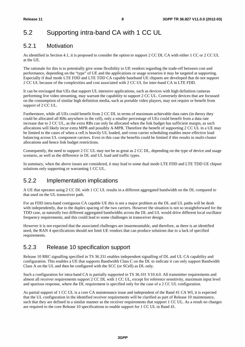
Table 5.3.2-1: Additional requirements
Spectrum emission limit [dBm]/BWChannel_CA ΔfOOB (MHz)
50+100RB (29.9 MHz)
75+75RB (30 MHz)
75+100RB (34.85 MHz)
100+100RB (39.8 MHz)
Measurement bandwidth
± 0-1 -22.5 -22.5 -23.5 -24 30 kHz ± 1-5.5 -13 -13 -13 -13 1 MHz
± 5.5-34.9 -25 -25 -25 -25 1 MHz ± 34.9-35 -25 -25 -25 1 MHz ± 35-39.85 -25 -25 1 MHz ± 39.85-44.8 -25 1 MHz
Additional spectrum emission requirements are signalled by the network for a B41_C UE by using NS_1X, with the exact NS value being defined when the CRs are written for this CA band, during CA specific configuration of PCell and SCell to indicate that the UE shall meet the additional SEM defined in this section. Note that the NS configuration of both PCell and SCell shall be common.
For the B41_A UE, the requirement to meet the additional SEM is indicated by NS_04 in the Release 8 elements of the SIB Type 2 message.
5.3.3 MPR for new 75 RB + 100 RB CC combination This section defines the MPR for the new CC combination of 75 RB + 100 RB. For all other combinations supported by Band 41, the MPR already defined in TS36.101 will be used.
5.3.3.1 Contiguous RB transmission
The need for MPR with contiguous allocations was studied against the requirements in Table 5.3.1-1 for 75 RB + 100 RB CC combination with:
- UTRAACLR1 = 33dB
- UTRAACLR2 = 36dB
- CA E-UTRAACRL = 30dB
- Spurious emissions limit was -30dBm with 1MHz measurement bandwidth
Simulation assumptions were as follows:
● PA operating point: UTRAACLR1 = 33 dBc with Pout = 22 dBm
● Modulator IQ – image = 25 dB
● Modulator carrier leakage = 25 dBc
● Modulator C_IM3 = 60 dBc
The PA operating point was set for each bandwidth so that with fully allocated carrier the reported UTRA ACLR1 level was 33 dB when 1 dB of MPR was applied.
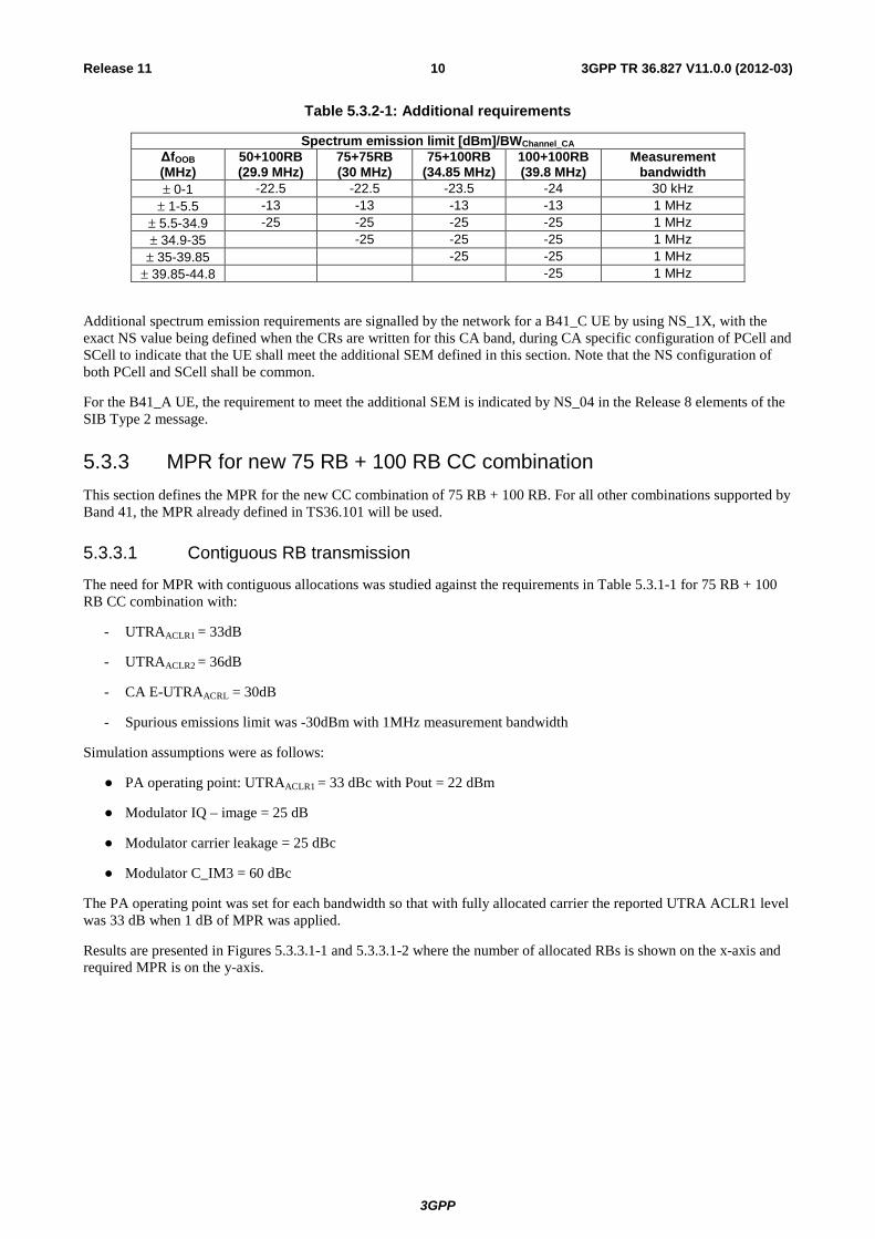
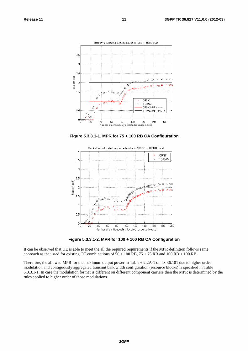
Results are presented in Figures 5.3.3.1-1 and 5.3.3.1-2 where the number of allocated RBs is shown on the x-axis and required MPR is on the y-axis.
3GPP
3GPP TR 36.827 V11.0.0 (2012-03)11Release 11
Figure 5.3.3.1-1. MPR for 75 + 100 RB CA Configuration
Figure 5.3.3.1-2. MPR for 100 + 100 RB CA Configuration
It can be observed that UE is able to meet the all the required requirements if the MPR definition follows same approach as that used for existing CC combinations of 50 + 100 RB, 75 + 75 RB and 100 RB + 100 RB.
Therefore, the allowed MPR for the maximum output power in Table 6.2.2A-1 of TS 36.101 due to higher order modulation and contiguously aggregated transmit bandwidth configuration (resource blocks) is specified in Table 5.3.3.1-1. In case the modulation format is different on different component carriers then the MPR is determined by the rules applied to higher order of those modulations.
3GPP
3GPP TR 36.827 V11.0.0 (2012-03)12Release 11
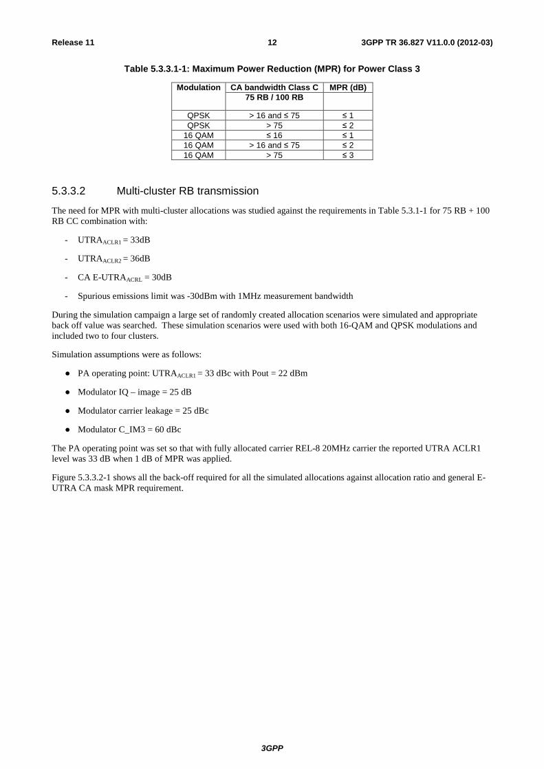
Table 5.3.3.1-1: Maximum Power Reduction (MPR) for Power Class 3
Modulation CA bandwidth Class C MPR (dB) 75 RB / 100 RB
QPSK > 16 and ≤ 75 ≤ 1 QPSK > 75 ≤ 2
16 QAM ≤ 16 ≤ 1 16 QAM > 16 and ≤ 75 ≤ 2 16 QAM > 75 ≤ 3
5.3.3.2 Multi-cluster RB transmission
The need for MPR with multi-cluster allocations was studied against the requirements in Table 5.3.1-1 for 75 RB + 100 RB CC combination with:
- UTRAACLR1 = 33dB
- UTRAACLR2 = 36dB
- CA E-UTRAACRL = 30dB
- Spurious emissions limit was -30dBm with 1MHz measurement bandwidth
During the simulation campaign a large set of randomly created allocation scenarios were simulated and appropriate back off value was searched. These simulation scenarios were used with both 16-QAM and QPSK modulations and included two to four clusters.
Simulation assumptions were as follows:
● PA operating point: UTRAACLR1 = 33 dBc with Pout = 22 dBm
● Modulator IQ – image = 25 dB
● Modulator carrier leakage = 25 dBc
● Modulator C_IM3 = 60 dBc
The PA operating point was set so that with fully allocated carrier REL-8 20MHz carrier the reported UTRA ACLR1 level was 33 dB when 1 dB of MPR was applied.
Figure 5.3.3.2-1 shows all the back-off required for all the simulated allocations against allocation ratio and general E-UTRA CA mask MPR requirement.

3GPP
3GPP TR 36.827 V11.0.0 (2012-03)13Release 11
Figure 5.3.3.2-1: 75RB + 100RB CA configuration against general E-UTRA SEM
It can be seen that all simulated allocations are compatible with the general E-UTRA spectrum emission mask; hence the MPR requirement in TS 36.101 can be used for 75 RB + 100 RBs.
5.3.4 A-MPR This section defines the A-MPR for the all CC combination considering the additional spectrum emission requirement defined in Section 5.3.2.
In the case of CA, A-MPR is not used in addition to MPR; either MPR is allowed to meet the mask defined in Section 5.3.1 or A-MPR is allowed to meet the mask defined in Section 5.3.2.
5.3.4.1 Contiguous RB transmission
The need for A-MPR with contiguous allocations was studied against following requirements in Table 5.3.2-1 for all allowed CC combinations, with:
- UTRAACLR1 = 33dB
- UTRAACLR2 = 36dB
- CA E-UTRAACRL = 30dB
- Spurious emissions limit was -30dBm with 1MHz measurement bandwidth
Simulation assumptions were as follows:
● PA operating point: UTRAACLR1 = 33 dBc with Pout = 22 dBm

3GPP
3GPP TR 36.827 V11.0.0 (2012-03)14Release 11
● Modulator IQ – image = 25 dB
● Modulator carrier leakage = 25 dBc
● Modulator C_IM3 = 60 dBc
PA operating point was set so that with fully allocated carrier REL-8 20MHz carrier the reported UTRA ACLR1 level was 33 dB when 1 dB of MPR was applied.
Results from these simulations are shown in the figures below.
Figure 5.3.4.1-1: Required A-MPR for 50 + 100 RB, QPSK

3GPP
3GPP TR 36.827 V11.0.0 (2012-03)15Release 11
Figure 5.3.4.1-2: Required A-MPR for 50 + 100 RB, 16QAM
Figure 5.3.4.1-3: Required A-MPR for 75 + 75 RB, QPSK
3GPP
3GPP TR 36.827 V11.0.0 (2012-03)16Release 11
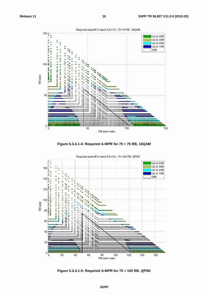
Figure 5.3.4.1-4: Required A-MPR for 75 + 75 RB, 16QAM
Figure 5.3.4.1-5: Required A-MPR for 75 + 100 RB, QPSK
3GPP
3GPP TR 36.827 V11.0.0 (2012-03)17Release 11
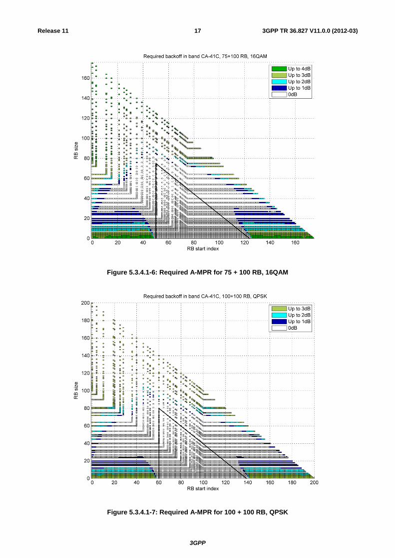
Figure 5.3.4.1-6: Required A-MPR for 75 + 100 RB, 16QAM
Figure 5.3.4.1-7: Required A-MPR for 100 + 100 RB, QPSK
3GPP
3GPP TR 36.827 V11.0.0 (2012-03)18Release 11
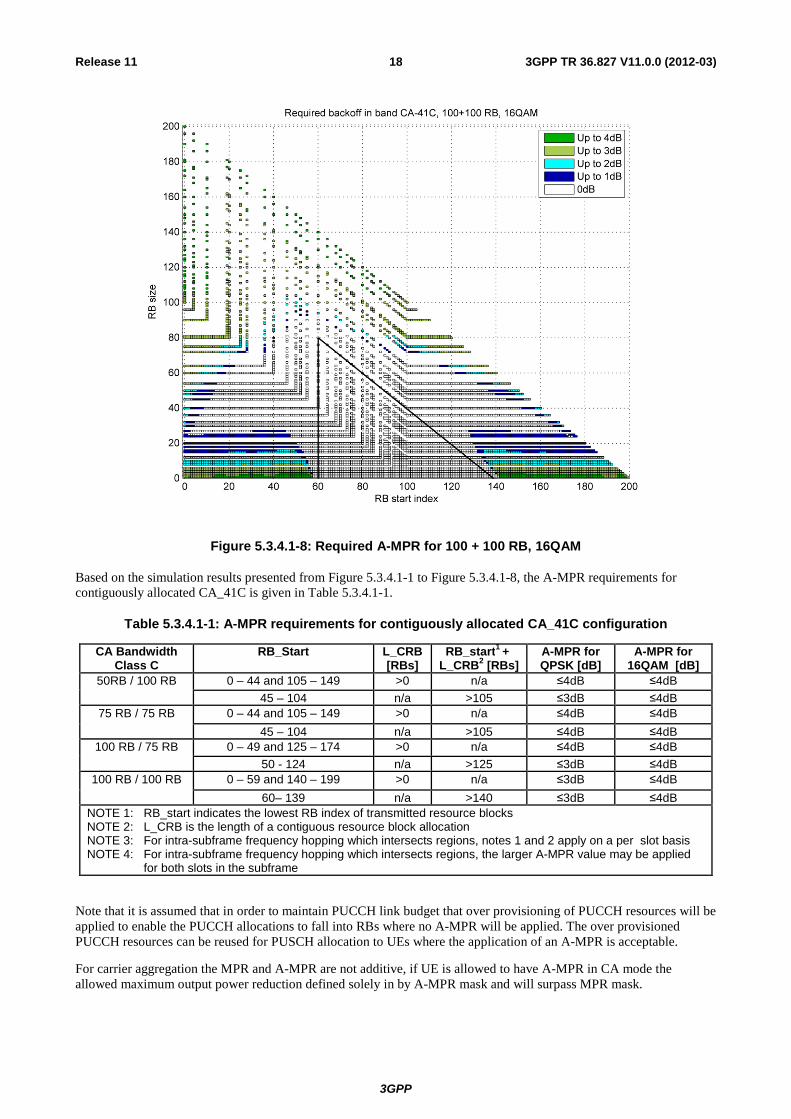
Figure 5.3.4.1-8: Required A-MPR for 100 + 100 RB, 16QAM
Based on the simulation results presented from Figure 5.3.4.1-1 to Figure 5.3.4.1-8, the A-MPR requirements for contiguously allocated CA_41C is given in Table 5.3.4.1-1.
Table 5.3.4.1-1: A-MPR requirements for contiguously allocated CA_41C configuration
CA Bandwidth Class C
RB_Start L_CRB [RBs]
RB_start1 + L_CRB2 [RBs]
A-MPR for QPSK [dB]
A-MPR for 16QAM [dB]
50RB / 100 RB 0 – 44 and 105 – 149 >0 n/a ≤4dB ≤4dB 45 – 104 n/a >105 ≤3dB ≤4dB
75 RB / 75 RB 0 – 44 and 105 – 149 >0 n/a ≤4dB ≤4dB 45 – 104 n/a >105 ≤4dB ≤4dB
100 RB / 75 RB 0 – 49 and 125 – 174 >0 n/a ≤4dB ≤4dB 50 - 124 n/a >125 ≤3dB ≤4dB
100 RB / 100 RB 0 – 59 and 140 – 199 >0 n/a ≤3dB ≤4dB 60– 139 n/a >140 ≤3dB ≤4dB
NOTE 1: RB_start indicates the lowest RB index of transmitted resource blocks NOTE 2: L_CRB is the length of a contiguous resource block allocation NOTE 3: For intra-subframe frequency hopping which intersects regions, notes 1 and 2 apply on a per slot basis NOTE 4: For intra-subframe frequency hopping which intersects regions, the larger A-MPR value may be applied
for both slots in the subframe
Note that it is assumed that in order to maintain PUCCH link budget that over provisioning of PUCCH resources will be applied to enable the PUCCH allocations to fall into RBs where no A-MPR will be applied. The over provisioned PUCCH resources can be reused for PUSCH allocation to UEs where the application of an A-MPR is acceptable.
For carrier aggregation the MPR and A-MPR are not additive, if UE is allowed to have A-MPR in CA mode the allowed maximum output power reduction defined solely in by A-MPR mask and will surpass MPR mask.
3GPP
3GPP TR 36.827 V11.0.0 (2012-03)19Release 11
5.3.4.2 Multi-cluster RB transmission
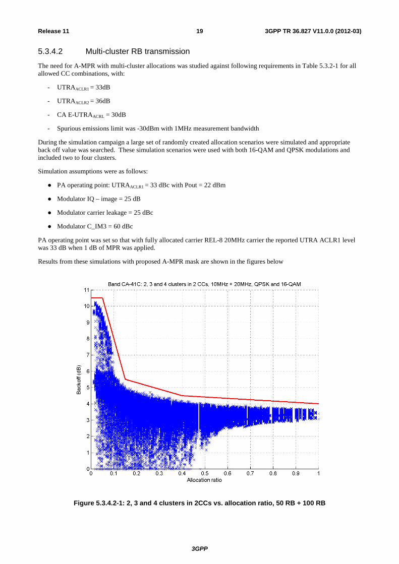
The need for A-MPR with multi-cluster allocations was studied against following requirements in Table 5.3.2-1 for all allowed CC combinations, with:
- UTRAACLR1 = 33dB
- UTRAACLR2 = 36dB
- CA E-UTRAACRL = 30dB
- Spurious emissions limit was -30dBm with 1MHz measurement bandwidth
During the simulation campaign a large set of randomly created allocation scenarios were simulated and appropriate back off value was searched. These simulation scenarios were used with both 16-QAM and QPSK modulations and included two to four clusters.
Simulation assumptions were as follows:
● PA operating point: UTRAACLR1 = 33 dBc with Pout = 22 dBm
● Modulator IQ – image = 25 dB
● Modulator carrier leakage = 25 dBc
● Modulator C_IM3 = 60 dBc
PA operating point was set so that with fully allocated carrier REL-8 20MHz carrier the reported UTRA ACLR1 level was 33 dB when 1 dB of MPR was applied.
Results from these simulations with proposed A-MPR mask are shown in the figures below
Figure 5.3.4.2-1: 2, 3 and 4 clusters in 2CCs vs. allocation ratio, 50 RB + 100 RB
3GPP
3GPP TR 36.827 V11.0.0 (2012-03)20Release 11
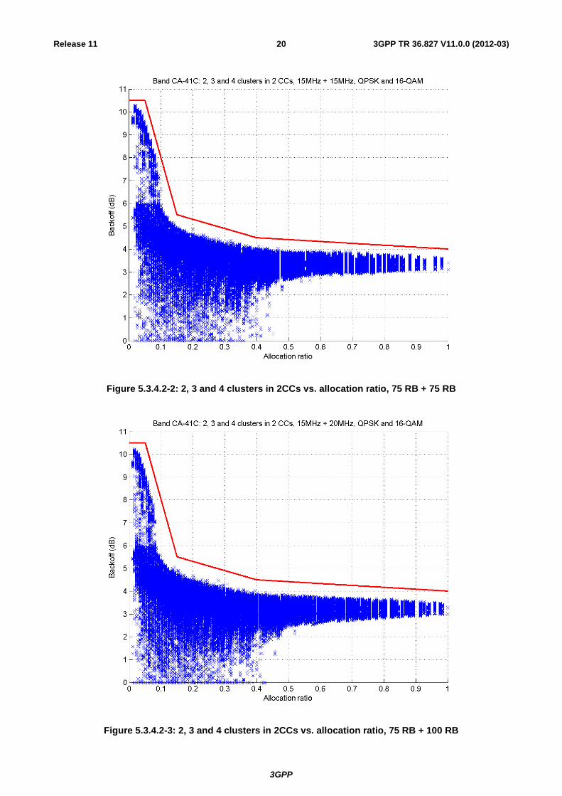
Figure 5.3.4.2-2: 2, 3 and 4 clusters in 2CCs vs. allocation ratio, 75 RB + 75 RB
Figure 5.3.4.2-3: 2, 3 and 4 clusters in 2CCs vs. allocation ratio, 75 RB + 100 RB

3GPP
3GPP TR 36.827 V11.0.0 (2012-03)21Release 11
Figure 5.3.4.2-4: 2, 3 and 4 clusters in 2CCs vs. allocation ratio, 100 RB + 100 RB
The results between different bandwidths are very similar. Therefore we propose a single A-MPR mask for all the bandwidth combinations in band CA_41C. All simulated allocations with the proposed mask are gathered together in Figure 5.3.4.2-5.

3GPP
3GPP TR 36.827 V11.0.0 (2012-03)22Release 11
Figure 5.3.4.2-5: All simulated allocations vs. allocation ratio
The mask shown in Figure 5.3.4.2-5 can be formally defined as follows
A-MPR = CEIL {MA, 0.5}
Where MA is defined as follows
MA = 10.5; 0 ≤ A < 0.05
-50.0A + 13.00; 0.05 ≤ A < 0.15
-4.0A + 6.10; 0.05 ≤ A < 0.40
-0.83A + 4.83; 0.40 ≤ A ≤ 1
Where A = NRB_alloc / NRB_agg.
For carrier aggregation the MPR and A-MPR are not additive, if UE is allowed to have A-MPR in CA mode the allowed maximum output power reduction defined solely in by A-MPR mask and will surpass MPR mask.
In Figure 5.3.4.2-6 is comparison between the general E-UTRA CA MPR mask and the proposed additional requirements mask for CA_41C

3GPP
3GPP TR 36.827 V11.0.0 (2012-03)23Release 11
Figure 5.3.4.2-6: Comparison of general E-UTRA CA MPR mask and CA_41C MPR mask
5.3.5 Reference sensitivity power level Section 7.3.1A in TS 36.101 deals with the reference sensitivity requirements for CA. In general TDD intra-band CA does not change the UE reference sensitivity requirement for CA, and as Band 41 does not introduce any new requirements that impact CA aspects of reference sensitivity, no changes need to be made to the existing CA requirements.
However the following changes are required in the definition of the uplink configuration to support reference sensitivity testing:
- Add a row in Table 7.3.1A-1 for B41_C to describe the UL allocation that shall be used for the case of a UE that supports Bandwidth Class C UL
- Add support for 100RB+75RB into Table 7.3.1A-1 for CA_41C only (other bands will be marked as n/a)
These changes are shown in the following table.
3GPP
3GPP TR 36.827 V11.0.0 (2012-03)24Release 11
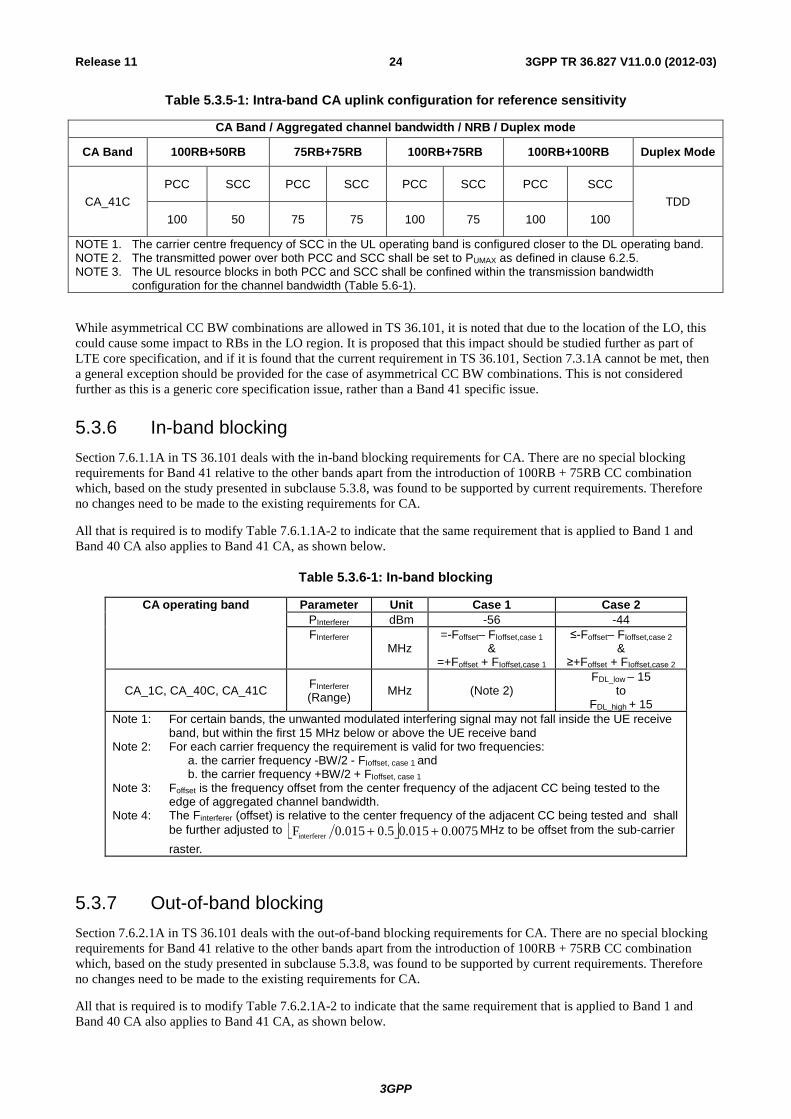
Table 5.3.5-1: Intra-band CA uplink configuration for reference sensitivity
CA Band / Aggregated channel bandwidth / NRB / Duplex mode
CA Band 100RB+50RB 75RB+75RB 100RB+75RB 100RB+100RB Duplex Mode
CA_41C PCC SCC PCC SCC PCC SCC PCC SCC
TDD 100 50 75 75 100 75 100 100
NOTE 1. The carrier centre frequency of SCC in the UL operating band is configured closer to the DL operating band. NOTE 2. The transmitted power over both PCC and SCC shall be set to PUMAX as defined in clause 6.2.5. NOTE 3. The UL resource blocks in both PCC and SCC shall be confined within the transmission bandwidth
configuration for the channel bandwidth (Table 5.6-1).
While asymmetrical CC BW combinations are allowed in TS 36.101, it is noted that due to the location of the LO, this could cause some impact to RBs in the LO region. It is proposed that this impact should be studied further as part of LTE core specification, and if it is found that the current requirement in TS 36.101, Section 7.3.1A cannot be met, then a general exception should be provided for the case of asymmetrical CC BW combinations. This is not considered further as this is a generic core specification issue, rather than a Band 41 specific issue.
5.3.6 In-band blocking Section 7.6.1.1A in TS 36.101 deals with the in-band blocking requirements for CA. There are no special blocking requirements for Band 41 relative to the other bands apart from the introduction of 100RB + 75RB CC combination which, based on the study presented in subclause 5.3.8, was found to be supported by current requirements. Therefore no changes need to be made to the existing requirements for CA.
All that is required is to modify Table 7.6.1.1A-2 to indicate that the same requirement that is applied to Band 1 and Band 40 CA also applies to Band 41 CA, as shown below.
Table 5.3.6-1: In-band blocking
CA operating band Parameter Unit Case 1 Case 2 PInterferer dBm -56 -44 FInterferer
MHz =-Foffset– FIoffset,case 1
& =+Foffset + FIoffset,case 1
≤-Foffset– FIoffset,case 2 &
≥+Foffset + FIoffset,case 2
CA_1C, CA_40C, CA_41C FInterferer (Range) MHz (Note 2)
FDL_low – 15 to
FDL_high + 15 Note 1: For certain bands, the unwanted modulated interfering signal may not fall inside the UE receive
band, but within the first 15 MHz below or above the UE receive band Note 2: For each carrier frequency the requirement is valid for two frequencies: a. the carrier frequency -BW/2 - FIoffset, case 1 and b. the carrier frequency +BW/2 + FIoffset, case 1 Note 3: Foffset is the frequency offset from the center frequency of the adjacent CC being tested to the
edge of aggregated channel bandwidth. Note 4: The Finterferer (offset) is relative to the center frequency of the adjacent CC being tested and shall
be further adjusted to ë û 0075.0015.05.00.015Finterferer ++ MHz to be offset from the sub-carrier raster.
5.3.7 Out-of-band blocking Section 7.6.2.1A in TS 36.101 deals with the out-of-band blocking requirements for CA. There are no special blocking requirements for Band 41 relative to the other bands apart from the introduction of 100RB + 75RB CC combination which, based on the study presented in subclause 5.3.8, was found to be supported by current requirements. Therefore no changes need to be made to the existing requirements for CA.
All that is required is to modify Table 7.6.2.1A-2 to indicate that the same requirement that is applied to Band 1 and Band 40 CA also applies to Band 41 CA, as shown below.

3GPP
3GPP TR 36.827 V11.0.0 (2012-03)25Release 11
Table 5.3.7-1: Out of band blocking
CA operating band Parameter Units Frequency range 1 range 2 range 3
PInterferer dBm -44 -30 -15
CA_1C, CA_40C, CA_41C FInterferer (CW)
MHz
FDL_low -15 to FDL_low -60
FDL_low -60 to FDL_low -85
FDL_low -85 to 1 MHz
FDL_high +15 to FDL_high + 60
FDL_high +60 to FDL_high +85
FDL_high +85 to +12750 MHz
5.3.8 UE receiver requirements for new 75 RB + 100 RB CC combination A simulation campaign was conducted to repeat the receiver requirement simulations for the new CC combination for Band 41 CA. This section presents the simulation setup and assumptions, results and conclusion that the requirements in TS 36.101 for the existing CC combinations can also be applied to the new CC combination of 75 RB + 100 RB.
5.3.8.1 Simulation set-up and assumptions
Simulation set-up is illustrated in the Figure 5.3.8.1-1 and the used receiver chain parameters are listed below.
Uplink (fUL)
Interferer (fi1)
Downlink (fDL)
+
DupAttenTR(48dB)
DupAttenAR(4dB)
+ LNA
Interferer has a very tight BB filter
Analog filter (4pole
Chebyshev)
ADCfs = 92.16MHz FIR
Analysispoint
Analog filter is designed first and
the mean attenuation in the interferer band is
measured – in this case 10dB
0 0.5 1 1.5 2 2.5 3
x 107
-60
-50
-40
-30
-20
-10
0
Freq, Hz
Gai
n, d
B
ADC filter characteristics
ADC filterInt regionMean in Int region
0 0.5 1 1.5 2 2.5 3
x 107
-90
-80
-70
-60
-50
-40
-30
-20
-10
0
10
Freq, Hz
Gai
n, d
B
ADC and baseband filter characteristics
HADC
HBB
HADC*HBB
Mean in Int region
Baseband filter is then designed to provide the remainder of the specified ACS. Currently it may
have an error of ~1dB.An iterative design approach could reduce this.
There is significant variation across the interferer band.
Noise(kTB)
ADC full scale is determined by measuring the total input signal power and adding a
margin, HADCdB
Figure 5.3.8.1-1 Simulation set-up
UE receiver chain parameters:
- Duplexer receive insertion loss = 4dB
- LNA gain = 4dB
- LNA noise figure = 5dB
- LNA IIP3 = -10 … +10 dBm
- LNA 1dB compression point = 10dB below IIP3

3GPP
3GPP TR 36.827 V11.0.0 (2012-03)26Release 11
- LNA IIP2 = 56dBm
- Image artefact not modelled.
- ADC sample rate = 92.16MHz
- ADC bits = 8
- ADC fading margin (above peak power) = 0 … 12dB
When simulations were done against ADC fading margin, LNA IIP3 was kept constant at -5 dBm. Correspondingly when simulations were done against LNA IIP3, then ADC fading margin was constant 5 dB.
Simulations were performed with both FDD and TDD duplexing modes. Metrics used for measuring results were error vector magnitude (EVM) and signal to noise + interference ratio (SNIR).
ACS
Adjacent Channel Selectivity (ACS) is a measure of a receiver's ability to receive an E-UTRA signal at its assigned channel frequency in the presence of an adjacent channel signal at a given frequency offset from the centre frequency of the assigned channel. ACS is the ratio of the receive filter attenuation on the assigned channel frequency to the receive filter attenuation on the adjacent channel(s).
Test parameters for ACS are specified in Section 7.5 of TS 36.101.
In-band blocking
In-band blocking is defined for an unwanted interfering signal falling into the UE receive band or into the first 15 MHz below or above the UE receive band at which the relative throughput shall meet or exceed the minimum requirement for the specified measurement channels.
Test parameters for in-band blocking are specified in Section 7.6.1 of TS 36.101.
Narrowband blocking
This requirement is measure of a receiver's ability to receive an E-UTRA signal at its assigned channel frequency in the presence of an unwanted narrow band CW interferer at a frequency, which is less than the nominal channel spacing.
Test parameters for Narrowband blocking are specified in Section 7.6.3 of TS 36.101.
Intermodulation characteristics
Intermodulation response rejection is a measure of the capability of the receiver to receiver a wanted signal on its assigned channel frequency in the presence of two or more interfering signals which have a specific frequency relationship to the wanted signal.

3GPP
3GPP TR 36.827 V11.0.0 (2012-03)27Release 11
Test parameters for intermodulation characteristics are specified in Section 7.8.1 of TS 36.101.
5.3.8.2 Simulation results
ACS
In-band blocking
Narrow-band blocking

3GPP
3GPP TR 36.827 V11.0.0 (2012-03)28Release 11
Intermodulation characteristics
5.3.8.3 Summary
Results for new CC combination 75+100RB are in line with results obtained in REL-10 CA WI for other CC combinations. Hence the existing contiguous intra-band CA Rx requirements can be extended to cover the new CC combinations.
5.4 Specific BS RF requirements A study of the existing technical specifications, including MSR, was conducted. The study concluded that no impact to BS RF specifications is required. Support for Band 41 CA in the BS specifications can be accommodated solely by a new entry for CA_41 in Table 5.5-2 in TS 36.104 and a new entry for CA_41 in Table 5.5-2 in TS 36.141. These changes are identified in Section 6.2 and 6.4.
5.5 Specific UE RRM requirements A study of the existing technical specifications was conducted. The study concluded that no impact to UE RRM specifications is required.

3GPP
3GPP TR 36.827 V11.0.0 (2012-03)29Release 11
6 Summary of required changes to E-UTRA specifications
6.1 Required changes to TS36.101 Required changes in UE RF specification TS 36.101 are shown in Table 6.1-1.
Table 6.1-1: Required changes in TS 36.101
Section Requirement Required changes in TS 36.101
5.5A Operating bands for CA A new row is expected to be added in Table 5.5A-1 to add CA_41 to the supported intra-band CA operating bands.
5.6A.1 Channel bandwidths per operating band for CA
A new row is expected to be added in Table 5.6A.1-1. for the supported E-UTRA bandwidths of intra-band contiguous B41 CA.
6.2.2A UE Maximum Output Power for intra-band contiguous CA
A new row is expected to be added in Table 6.2.2A-1. It’s proposed to evaluate the appropriate UE maximum output power requirement for intra-band contiguous B41 CA.
6.2.4A UE Maximum Output Power with additional requirements for CA
It’s proposed to evaluate the appropriate A-MPR requirement for intra-band contiguous Band 41 CA with 2 CCs on the UL.
6.6.2.2.2A Additional Spectrum Emission Mask for B41 CA
It’s proposed to add a new section in 6.6.2.2.2A to define the CA SEM for class C for NS_04 (this will adapt Table 6.6.2.1A-1 to meet current FCC requirements)
7.3.1A Minimum requirements (QPSK) for CA
A new row is expected to be added in Table 7.3.1A-1 for intra-band CA uplink configuration for reference sensitivity.
7.6.1.1A In-band blocking for intra-band contiguous CA
Appropriate changes are expected in Table 7.6.1.1A-2. It’s proposed to evaluate whether the existing CA_40C in-band blocking requirement is valid for CA_41C or not.
7.6.2.1A Out-of-band blocking for intra-band contiguous CA
Appropriate changes are expected in Table 7.6.2.1A-2. It’s proposed to evaluate whether the existing CA_40C out-of-band blocking requirement is valid for CA_41C or not.
6.2 Required changes to TS36.104 Required changes in BS RF specification TS 36.104 are shown in Table 6.2-1.
Table 6.2-1: Required changes in TS 36.104
Section Requirement Required Changes in TS 36.104
5.5 Operating bands A new row is expected to be added in Table 5.5-2 to support B41 intra-band contiguous carrier aggregation configuration.
6.3 Required changes to TS36.133 No changes required in TS 36.133.
6.4 Required changes to TS36.141 Required changes in BS test specification TS 36.141 are shown in Table 6.4-1.

3GPP
3GPP TR 36.827 V11.0.0 (2012-03)30Release 11
Table 6.4-1: Required changes in TS 36.141
Section Requirement Required Changes in TS 36.141
5.5 Operating bands A new row is expected to be added in Table 5.5-2 to support B41 intra-band contiguous carrier aggregation configuration.
6.5 Required changes to TS36.307 Required changes in TS 36.307 are shown in Table 6.5-1.
Table 6.5-1: Required changes in TS 36.307
Section Requirement Required Changes in TS 36.307
8 Band 41 independent of release
Expect to add some changes to 36.307 Rel-10 to provide the appropriate pointers to the Rel-11 spec to enable backdating of band 41 CA to Rel-10.
6.6 Required changes to TS37.104 No changes required in TS 37.104.
6.7 Required changes to TS37.141 No changes required in TS 37.141.
7 Project plan The high level plan proposed in [2] and agreed in RAN#52 is to complete the LTE_CA_B41-Core part by September 2012 and the LTE_CA_B41-Perf by December 2012.
It is expected that support for 2 CC downlink and 1 CC uplink will be completed first, followed by extension to provide support for 2 CC uplink.
The detailed task schedule is provided in the following subclause.
7.1 Schedule and Work Task Status Table 7.1-1 summarises the schedule and work task status for LTE_CA_B41 WI.
3GPP
3GPP TR 36.827 V11.0.0 (2012-03)31Release 11
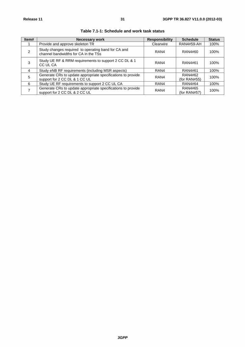
Table 7.1-1: Schedule and work task status
Item# Necessary work Responsibility Schedule Status 1 Provide and approve skeleton TR Clearwire RAN4#59-AH 100%
2 Study changes required to operating band for CA and channel bandwidths for CA in the TSs RAN4 RAN4#60 100%
3 Study UE RF & RRM requirements to support 2 CC DL & 1 CC UL CA RAN4 RAN4#61 100%
4 Study eNB RF requirements (including MSR aspects) RAN4 RAN4#61 100%
5 Generate CRs to update appropriate specifications to provide support for 2 CC DL & 1 CC UL RAN4 RAN4#62
(for RAN#55) 100%
6 Study UE RF requirements to support 2 CC UL CA RAN4 RAN4#64 100%
7 Generate CRs to update appropriate specifications to provide support for 2 CC DL & 2 CC UL RAN4 RAN4#65
(for RAN#57) 100%
3GPP
3GPP TR 36.827 V11.0.0 (2012-03)32Release 11
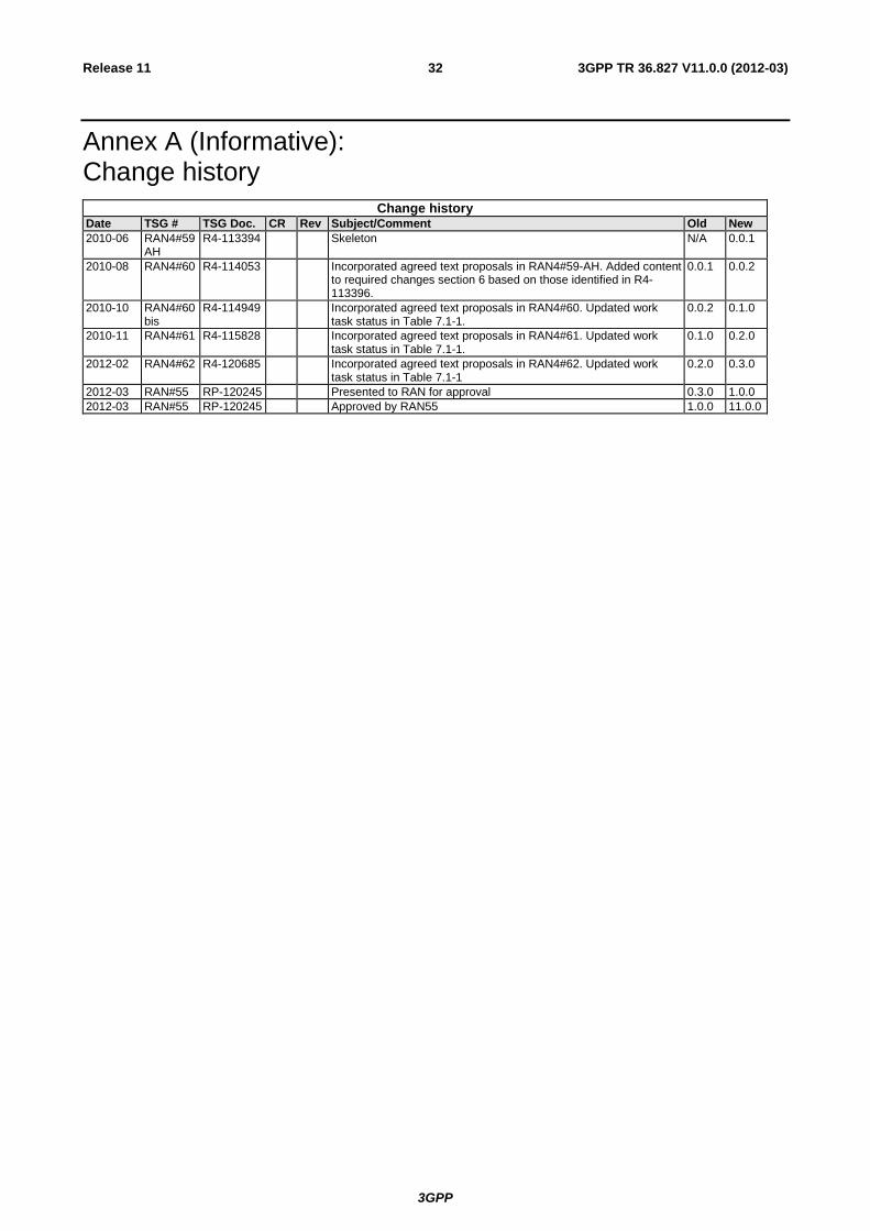
Annex A (Informative): Change history
Change history Date TSG # TSG Doc. CR Rev Subject/Comment Old New 2010-06 RAN4#59
AH R4-113394 Skeleton N/A 0.0.1
2010-08 RAN4#60 R4-114053 Incorporated agreed text proposals in RAN4#59-AH. Added content to required changes section 6 based on those identified in R4-113396.
0.0.1 0.0.2
2010-10 RAN4#60bis
R4-114949 Incorporated agreed text proposals in RAN4#60. Updated work task status in Table 7.1-1.
0.0.2 0.1.0
2010-11 RAN4#61 R4-115828 Incorporated agreed text proposals in RAN4#61. Updated work task status in Table 7.1-1.
0.1.0 0.2.0
2012-02 RAN4#62 R4-120685 Incorporated agreed text proposals in RAN4#62. Updated work task status in Table 7.1-1
0.2.0 0.3.0
2012-03 RAN#55 RP-120245 Presented to RAN for approval 0.3.0 1.0.0 2012-03 RAN#55 RP-120245 Approved by RAN55 1.0.0 11.0.0