Embed Size (px)
Citation preview

mariusz maŚlak*, anna TkaCzYk**
a semiGraPHiC aPProaCH To THe fire resisTanCe assessmenT of a GaBle sTeel frame
CzĘŚCiowo GrafiCzna oCena odPornoŚCi oGnioweJ sTaloweJ ramY PorTaloweJ z rYGlem
dwusPadowYm
a b s t r a c t
an alternative design approach, helpful in the critical temperature evaluation for a gable steel frame exposed to fire, is proposed and discussed in this article. This approach is based on the specification of a system of equilibrium formulae, generalized to the case of fire. all these equations result from the graphical identification of the redundant bending moment distribution in the frame members relating to the particular collapse mechanisms being kinematically admissible. only such a mechanism which corresponds to the activation of a suitable sequence of the appropriate number of plastic hinges while maintaining the requirements of the classical bending moment redistribution is recognized as conclusive for the considered frame structure.
Keywords: gable frame, fire, critical temperature, fire resistance, static approach
s t r e s z c z e n i e
w artykule zaproponowano alternatywne podejście do oceny temperatury krytycznej ramy stalowej z ryglem dwuspadowym, eksponowanej ogniowo w warunkach pożaru. Proponowana metodyka obliczeń opiera się na specyfikacji układu równań równowagi, uogólnionych na przypadek pożaru, z których każde wynika z graficznej identyfikacji rozkładu momentów nadliczbowych towarzyszącego analizowanemu kinematycznie dopuszczalnemu mechanizmowi ruchu. miarodajny dla rozważanej ramy jest mechanizm kojarzony z uruchomieniem sekwencji odpowiedniej liczby przegubów plastycznych przy równoczesnym zachowaniu zasad klasycznej redystrybucji momentów zginających.
Słowa kluczowe: rama z ryglem dwuspadowym, pożar, temperatura krytyczna, odporność ogniowa, podejście statyczne
* d.sc. eng., prof. CuT, mariusz maślak, institute of Building materials and structures, faculty of Civil engineering, Cracow university of Technology.
** m.sc. eng. anna Tkaczyk, Bauko design Company, kielce, Poland.
TECHNICAL TRANSACTIONSCIVIL ENGINEERING
6-B/2014
CZASOPISMO TECHNICZNEBUDOWNICTWO
68
1. Introduction
it is common knowledge that the ultimate resistance of the considered loadbearing frame can be easily evaluated due to the succeeding analysis of all collapse mechanisms which may potentially occur in such a structure. The type and the number of the mechanisms required for detailed consideration depend on the support conditions previously assumed. The application of such a well justified approach allows us to quantify the plastic reserve of a structure which is a consequence of the inevitable bending moment redistribution in structural members. However, it is essential to underline the fact that the solution obtained in this way cannot be interpreted as the conclusive value of the frame’s plastic resistance, but only as its estimated upper limit. such an evaluation should be considered as an equivalent to the actual plastic resistance only in cases where it can be verified by an independent study based on the application of the classical static approach to the analysis.
The basis of the applied methodology adopted for the persistent design situation when the structure remains at room temperature is the virtual work equation written as follows:
,i i pl j ji j
P Mλ δ = ϕ∑ ∑ (1)
and specified separately for each mechanism previously identified. in such a formula, index i is the number of the load Pi which performs work at the displacement δi being generated by this external force; whereas, index j denotes the location of the plastic hinge being a component of the considered collapse mechanism. The successively formed plastic hinges are characterized by the crosssection resistance Mpl, j (i.e. Mc
pl, j for the frame columns and Mbpl, j
for the frame beam, respectively). moreover, each of these hinges located in section j is associated with the rotation φj which will occur when the analysed potential failure mechanism is activated. factor λ is the load multiplier, in accordance with the assumption that all external loads applied to the frame grow in time proportionally to the one common parameter. Consequently, the load Pi can increase only up to the point in time when Pi = Pi,ult. This ultimate
value may be defined by the multiplier min min kkλ = λ (because Pi,ult = λminPi) which is quan
tified as a minimum of all the multipliers λk resulting from the analysis of each kinematically admissible collapse mechanism (numbered by the index k = 1, …, m) [1].
The aim of the presented paper is to generalize this evaluation procedure in order for it to be accurate for calculations regarding situations of a structurally significant fire. it is important that in relation to such exceptional events, the formal assumptions have to be quite different from those previously mentioned. on the one hand, it is necessary to accept that all external loads applied to the structure remain constant during the whole duration of the fire, but on the other hand, it is essential to assume that the member temperature Θ is, at the same time, monotonically increasing. Conclusively, the temperature Θcr, relating to the frame collapse, is generally interpreted as the critical temperature both for the analysed structure and for the assumed level and arrangement of its external load. let us note that in the situation of a fire, thermal influences induce the selfequilibrating field of the internal forces in the structure, generated as a result of thermal strain constraints. However, such forces have no influence on the critical temperature evaluation for the considered frame because in eq. (1), only values of a crosssection plastic resistance Mpl,j are taken into account.

69
The generalization of a classical design procedure to the study of cases of fire is not very difficult if the location of all possible plastic hinges is known in advance and explicitly determined. This means that the conclusive frame collapse mechanism is then possible for identification without significant doubt. The appropriate design algorithm, which is helpful in assessing the critical temperature of a steel frame when exposed to fire, was proposed and discussed in detail by the authors in [2], and afterwards in [3], with further examples and conclusions. However, it seems to be suitable for use only if the input data related to the frame geometry, as well as to the external load arrangement, are not very complex and, moreover, if these are not causing computational inconveniences. in this study, the case of a gable (pitchedroof) steel frame is analysed in detail. all external loads applied to the structure are assumed to be concentrated. in fact, if they are vertical, then they can be transferred into the loadbearing frame by existing purlins. Complementarily, in the case of the horizontal loads, such a transfer is realized by wall beams. let us note that in the presented study, the potential plastic hinges can occur only in those places where the concentrated loads are applied. This means that for each collapse mechanism which can be activated in the frame, the possible location of all hinges can be determined a priori. However, it is not quite so easy to identify the configuration of the conclusive collapse mechanism, i.e. the one that will be generated first, and, as a consequence, will be characterized by the lowest value of the frame critical temperature. To do this in practice, the previous detailed analysis of each mechanism being kinematically admissible have to be performed separately. To make the process of the evaluation of critical temperature for the whole structure more illustrative, as well as to improve it to be simpler and faster for the designer, an alternative semigraphical design technique is recommended by the authors in this article. The proposed methodology is based on the specification of the appropriate equilibrium conditions and the number of necessary formulae of this type depends on the redundancy of the considered gable frame. The application of such an approach leads to the evaluation of the frame critical temperature which should be treated only as the lower limitation of its actual value, not as the upper one as was mentioned above when the classical design approach was presented. This fundamental difference results from the fact that the proposed equilibrium formulae can be interpreted as a suitable generalization of those which are typical of the classical static approach to evaluate the ultimate resistance of a structure. let us note that the assessment obtained in this way is always safe. This is in contrast with evaluations resulting from the application of the typical kinematic approach which are frequently too optimistic and overestimated.
2. Cross-section plastic resistance under fire conditions
The crosssection plastic resistance Mpl,j depends on the value of the yield point fy specified for the steel which the considered frame is made of. it is a wellknown fact that under fire conditions, such a material yield point is considerably reduced because of the high temperature Θ influence. according to the recommendation given in the standard Pnen 199312 [4], one can adopt the reduction ratio designated for the characteristic value fy,20 and equal to ky,Θ = fy,Θ/fy,20. detailed values of this factor, relating to the constructional mild steel and associated with the particular member temperature, are presented in Tab. 1. as is shown, the room temperature Θ = 20°C is interpreted here as the reference temperature.
70
Consequently, it is easy to note that fy,Θ = ky,Θfy,20. moreover, it is necessary to underline that the same values of the factor ky,Θ can also be used for the assessment of the reduction ratio of the design value of the steel yield point, because the suitable partial safety factors γM are usually adopted to be quantitatively the same both for the persistent design situation and for the accidental situation of a fully developed fire. This means that γM = γM,fi = 1.0 where the lower index “fi” is related to the case of a fire.
T a b l e 1
Reduction factors ky,Θ relating to the characteristic value of material yield point and designated for constructional mild steel exposed to fire, according to PN-EN 1993-1-2 [4]
Θa
[°C]
100≤ 200
300
400
500
600
700
800
900
1,000
1,100
1,200
ky,Θ
1.000
1.000
1.000
1.000
0.780
0.470
0.230
0.110
0.060
0.040
0.020
0.000
Conclusively, if it is assumed that the temperature distribution across the member crosssection is uniform, which means that such a member is uniformly heated and the bending modulus Wpl remains constant during the whole duration of the fire, then the reduction of the crosssection plastic resistance at temperature Θ, in relation to the corresponding resistance specified for the room steel temperature, may be evaluated as follows:
MM
k W fW f
kpl j
pl j
M y pl y
M fi pl yy
, ,
, ,
, ,
, ,,
Θ ΘΘ
20
20
20
= =γ
γ (2)
3. Description of the frame analysed in the example
in the example presented in this article, two kinds of gable steel frame are examined in detail. Both of them have the same dimensions – a height equal to 10 m and a span equal to 30 m; however, they differ from each other in their supporting conditions. The first is simply supported, whereas the second is fully fixed in its foundations (see fig. 1 in which L = 2 m and h = 3 m). it is also assumed that in both cases, the frame columns are designed from the iPe 500 (for which Wc
pl = 2,194 mm3) and the frame beams from the iPe 360 (for which Wb
pl = 1,019 mm3) steel sections. moreover, all frame members are made of the s235 grade mild steel, with the characteristic value of its yield point equal to fy = 235 mPa. referring to such accepted input data, it is easy to calculate the plastic resistance of the particular member crosssections, i.e. Mc
pl = Wcplfy = 515.6 knm in the case of the frame columns and Mb
pl = Wbplfy
= 239.5 knm in relation to the frame beams. This gives a ratio of proportionality equal to α = Mb
pl/Mcpl = 0.465. let us note that the value of this ratio remains constant during the whole
duration of the fire because the values of the bending modulus, both of Wcpl and of Wb
pl, are

71
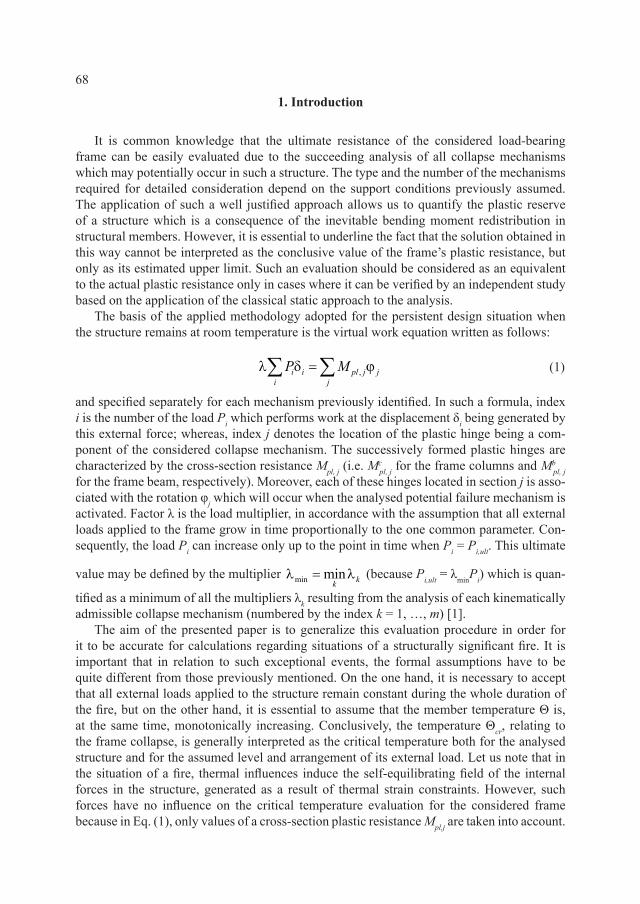
independent of the material temperature. such a conclusion is fully adequate if the fully developed fire is modelled as the reliable fire scenario and the considered frame is exposed to this type of fire. according to this model, the member temperature distribution is uniform, both across the member crosssections and along the whole of the members length; however, the value of this temperature is increasing together with the fire’s intensity. The load arrangement dealing with the external loads applied to the frame is shown in detail in fig. 1. as is shown, this is the same for both frame types considered in the example.
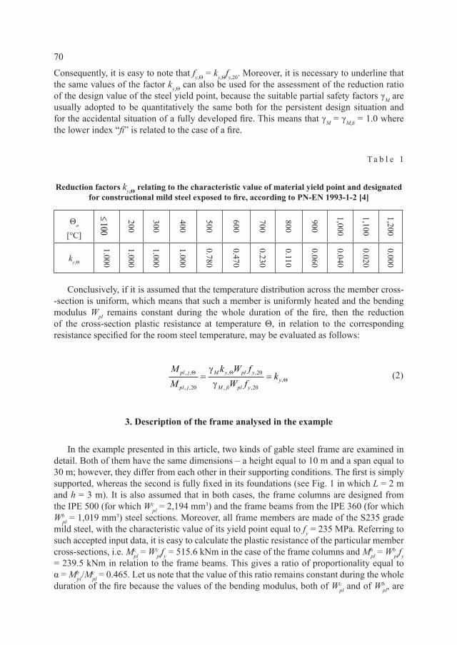
in fig. 2, selected possible frame collapse mechanisms are presented. These are kinematically admissible in the case of the frame with fully fixed supports. it is noteworthy that the semi graphic design technique, recommended by the authors in this article, provides the soughtafter solution much faster and, furthermore, it seems to be more illustrative and easier for interpretation than that obtained through the application of the typical calculation methodology.
4. Results obtained for the simply supported frame exposed to fire
let us start with the analysis of a simply supported frame exposed to fire. The first step is to find the values of redundant internal forces. To do this, the auxiliary, statically determinate frame static scheme should be previously specified. let such a scheme in this example is the one presented in fig. 3, with the internal horizontal force H interpreted as an external action applied to the right frame support. This force generates the redundant bending moment distribution with the values, from M1
0 up to M019, presented in Tab. 2.
fig. 1. analytical schemes and load arrangement specified for the frames considered in the example. above – the frame being simply supported. Below – the frame being fully fixed in its foundations,
L = 3 m, h = 2 m

72
fig. 2. selected potential collapse mechanisms, kinematically admissible for the frame being fully fixed in its foundations: 151519, 1101519, 581215, 561115 and 151115, respectively
fig. 3. statically determinate frame static scheme, adopted to identify the distribution of the redundant internal forces
as a consequence of the application of external forces with the arrangement shown in fig. 1 to the considered frame characterized by the auxiliary statically determinate static scheme the bending moment distribution is induced in such a structure, presented in fig. 4.
next, the primary task is to determine the values of the force H as well as values of the reduction factor ky,Θ that fulfil the equilibrium conditions specified for the case of fire and for the considered collapse mechanism. detailed analysis of the diagram presented in fig. 4 leads to the conclusion that the collapse mechanism, according to which the plastic hinges occur in sections numbered as 10 and 15, is reliable for the conditions adopted in the example. let us note that in this case, the redundant bending moment diagram is symmetrical (see fig. 6) then the greater value of a qualitative difference, M10 – M15 in comparison with the difference M10 – M5 being characteristic for the mechanism 5–10 which is also possible to

73
occur, determines the choice of the first of the compared mechanism as conclusive. However, two different possible cases should be examined separately. The first refers to a situation when the plastic hinge generated in the frame section denoted as 15 occurs in the frame column, whereas the second, in the frame beam. let us start from the analysis of the first case, presented in fig. 5.
T a b l e 2
Values of the bending moment generated in the simply supported frame by redundant horizontal force H (see Fig. 3)
0 01 19 0M M= = 0 0
2 18M M Hh= = 0 03 17 2M M Hh= =
0 04 16 3M M Hh= = 0 0
5 15 4M M Hh= = 0 06 14
145
M M H H h = = +
0 07 13
245
M M H H h = = +
0 08 12
345
M M H H h = = +
0 09 11
445
M M H H h = = +
010 5M Hh=
fig. 4. Bending moment distribution generated by the external load arrangement applied to the frame with a statically determinate static scheme, assumed previously
fig. 5. Collapse mechanism 1015 specified for the case when the plastic hinge generated in section 15 is activated in the frame column

74
fig. 6. redundant bending moment Mi0 diagram obtained for the force H previously calculated
according to eq. (3)
in such circumstances, the system of two equilibrium formulae can be expressed as follows (see fig. 7):
010 10 , ,
015 15 ,
b cy pl y pl
cy pl
M M k M k MM M k M
Θ Θ
Θ
− = = α − = −
(3)
substitution to eq. (3) of the values M10 = 243.75 knm and M15 = 24.00 knm taken from fig. 4, as well as the adoption to these formulae of the values M0
10 and M015 compiled previously
in Tab. 2, lead to the following solutions: H = 18.584 kn and ky,Θ = 0.242, which means that the critical temperature specified for the whole frame is equal to Θcr = 666°C (see Tab. 1). in fact, the force H calibrated in this way generates the redundant bending moment Mi
0 diagram shown in detail in fig. 6. Consequently, the redistribution of the bending moments is performed in the frame members as is shown in fig. 7. it is easy to see the occurrence of the equilibrium:
( )10 15243.75 185.84 0.465 24.00 148.67 57.9 knmM M∗ ∗= − = α = ⋅ − = (4)
and also the conclusive equivalence:
( ), , 0.242 239.5 57.9 knmb b bpl pl cr y plM M k MΘ Θ= Θ = = ⋅ = (5)
fig. 7. Bending moment redistribution obtained for the redundant bending moment diagram presented in fig. 6

75
However, it is important to underline the fact that such evaluation, i.e. Θcr = 666°C, cannot be recognized as a correct assessment of the frame critical temperature because it is possible to identify in fig. 7 some sections, located in the considered frame beam, in which the limitation Mi
* < Mi,pl,Θ is not satisfied. let us note that the detailed calculation of the value M5
* and also of the value M*15 is sufficient to reject the solution obtained in the proposed
manner. This conclusion means that the analysed collapse mechanism cannot be treated as the reliable one in the presented example.
Quantitatively different evaluation of critical temperature Θcr is obtained when the second possible collapse mechanism is analysed in detail, according to which, both plastic hinges are generated in the frame beam (see fig. 8). in this case, eq. (3) has the form:
M M k MM M k M
y plb
y plb
10 100
15 150
− =− = −
,
,
Θ
Θ
(6)
which gives: H = 14.875 kn and ky,Θ = 0.397 being an equivalent of the assessment Θcr = 592°C.
fig. 8. Collapse mechanism 1015 specified for the case when the plastic hinge generated in section 15 is activated in the frame beam
fig. 9. redundant bending moment Mi0 diagram obtained for the force H previously calculated
according to eq. (6)

76
such a solution can be easily confirmed by the suitable moment redistribution presented in figs. 9 and 10. The adequate equilibrium condition is now formulated as follows:
10 15243.75 148.75 24.00 119.00 95.0 knmM M∗ ∗= − = = − = (7)
and also the conclusive equivalence:
( ), , 0.397 239.5 95.0 knmb b bpl pl cr y plM M k MΘ Θ= Θ = = ⋅ = (8)
it is important to note that in this case, the limitation Mi* < Mi,pl,Θ is satisfied in all
sections located in the frame members (obviously, except for the sections denoted as 10 and 15 for which the equivalence M*
10 = M*15 = Mb
pl,Θ occurs). as a conclusion, the evaluation Θcr = 592°C can be understood as the reliable frame critical temperature value being sought by the fire safety expert.
fig. 10. Bending moment redistribution obtained for the redundant bending moment diagram presented in fig. 9
5. Example of the frame with fully fixed supports
when the examined frame has all supports designed to be fully fixed (see fig. 1), then the number of redundant forces necessary to calculate by the specification of the system of the appropriate equilibrium conditions is much greater. let the auxiliary statically determinate static scheme, helpful in the specification of all redundant forces previously identified, be assumed as shown in fig. 11.
fig. 11. statically determinate frame static scheme adopted to identify the distribution of the redundant internal forces

77
fig. 12. Bending moment distribution generated by external load arrangement applied to the frame with a statically determinate analytical scheme previously assumed
T a b l e 3
Values of the bending moment generated in the frame with fully fixed supports by redundant forces M, H, R (see Fig. 11)
01 5 5M M Hh RL= + − 0
2 4 5M M Hh RL= + −
03 3 5M M Hh RL= + − 0
4 2 5M M Hh RL= + −
05 5M M Hh RL= + − 0
64 45
M M Hh RL= + −
07
3 35
M M Hh RL= + − 08
2 25
M M Hh RL= + −
09
15
M M Hh RL= + − 010M M=
011
15
M M Hh RL= + + 012
2 25
M M Hh RL= + +
013
3 35
M M Hh RL= + + 014
4 45
M M Hh RL= + +
015 5M M Hh RL= + + 0
16 2 5M M Hh RL= + +
017 3 5M M Hh RL= + + 0
18 4 5M M Hh RL= + +
019 5 5M M Hh RL= + +

78
as is shown, the values of three kinds of redundant forces (M, H and R) have to be calculated at the beginning of the analysis directly from the suitable equilibrium formulae. subsequently, the distribution of the redundant bending moments Mi
0 should be specified, taking into account the equations presented in Tab. 3. The distribution of the bending moments generated as a result of the application of the external load arrangement presented in fig. 1 to the frame structure with the static scheme being statically determinate is shown in detail in fig. 12 (let us note that such moments are now negative both in the frame beam and in the frame columns).
The detailed analysis of a bending moment distribution shown in fig. 12 leads to the conclusion that the reliable collapse mechanism can be only this one according to which three plastic hinges are activated in the frame beam, whereas the fourth one in a frame column. furthermore, such “beam” hinges have to induce in sections denoted as 5, 10 and 15, while the “column” one – in one from the frame supports, for example in section 1 or in section 19. let us start from the analysis of the mechanism 151015. This is presented in detail in fig. 13.
fig. 13. Collapse mechanism 151015 specified for the case when the plastic hinges generated in sections 5 and 15 are activated in the frame beam
for such a case, the suitable system of four equilibrium formulae is expressed as follows:
01 1 , ,
05 5 ,
010 10 ,
015 15 ,
bplc
y pl y
by pl
by pl
by pl
MM M k M k
M M k M
M M k M
M M k M
Θ Θ
Θ
Θ
Θ
+ = =
α + = − + = + = −
(9)
This gives the following solutions: M = 60.52 knm; R = –2.05 knm; ky,Θ = 0.253. such an evaluation of ky,Θ is the equivalent of the assessment of the frame critical temperature being equal to Θcr = 660°C (see Tab. 1). However, before accepting this temperature value as the conclusive critical temperature of the considered loadbearing structure, it is necessary to perform the semigraphic procedure of moment redistribution in the frame members. The basic objective of this is to verify whether the limitation M*
i < Mi,pl,Θ is satisfied in all sections located outside plastic hinges. in fact, in this example, the redundant forces calculated from eq. (9) give the redundant moment diagram presented in fig. 14.

79
as a result of such an evaluation, the conclusive bending moment redistribution has the form shown in detail in fig. 15.
fig. 14. redundant bending moment Mi0 diagram obtained for the forces M, H, R previously
calculated according to eq. (9)
fig. 15. Bending moment redistribution obtained for the redundant bending moment diagram presented in fig. 14
as is shown, the equivalences previously assumed are fully satisfied because the following occurs:
( )1 5 10
15
0.465 124.50 254.79 184.50 123.98 0 60.52
123.00 62.48 60.52 knm
M M M
M
∗ ∗ ∗
∗
= ⋅ − + = = − + = = + =
= = − + =
(10)
and also it is true that:
( ), , 0.253 239.5 60.52 knmb b bpl pl cr y plM M k MΘ Θ= Θ = = ⋅ = (11)
nevertheless, the temperature value Θ = 660°C calculated from eq. (9) cannot be interpreted as the critical one for the considered frame structure because it is easy to conclude that in section 19 (see fig. 15), the following inequality occurs

80
M M plc
19 3 00 193 29 190 29 0 253 515 6 130 45∗ = − + = > = ⋅ =. . . . . ., kNm kNmΘ . This means that the considered collapse mechanism is not reliable for the initial conditions previously assumed.
let us analyse the collapse mechanism 5101519 presented in fig. 16. The system of the suitable equilibrium formulae now has the form:
019 19 , ,
05 5 ,
010 10 ,
015 15 ,
bplc
y pl y
by pl
by pl
by pl
MM M k M k
M M k M
M M k M
M M k M
Θ Θ
Θ
Θ
Θ
+ = =
α + = − + = + = −
(12)
which gives the solutions: M = 65.90 knm; H = 10.97 kn; R = –2.05 kn; ky,Θ = 0.275 being an equivalent of the assessment Θcr = 647°C (see Tab. 1).
fig. 16. Collapse mechanism 5101519 specified for the case when the plastic hinges generated in sections 5 and 15 are activated in the frame beam
The redundant forces, calculated from eq. (12), lead to the diagram of the redundant bending moments shown in fig. 17.
finally, the suitable bending moment redistribution is presented in detail in fig. 18. it is graphically made to verify the assessment of the frame critical temperature obtained from eq. (12). it can be seen that the following occurs:
( )5 10 15
19
184.50 118.60 0 65.90 123.00 57.10
0.453 3.00 144.88 65.90 knm
M M M
M
∗ ∗ ∗
∗
= − + = = + = = − + =
= = ⋅ − + = (13)
and also that:
( ), , 0.275 239.5 65.90 knmb b bpl pl cr y plM M k MΘ Θ= Θ = = ⋅ = (14)

81
fig. 17. redundant bending moment Mi0 diagram obtained for the forces M, H, R previously
calculated according to eq. (12)
fig. 18. Bending moment redistribution obtained for the redundant bending moment diagram presented in fig. 17
The visual observation of the redistribution diagram shown in fig. 18 leads to the conclusion that the temperature Θcr = 647°C can be treated as its critical value for the considered frame structure because in all member sections (outside those connected to the activated plastic hinges), the limitation M*
i < Mi,pl,Θ is fully satisfied.
6. Concluding remarks
an alternative calculation procedure proposed by the authors in this article seems to be simpler and more effective in relation to the classical kinematic approach usually used in the evaluation of the critical temperature of a frame structure exposed to fire. The choice of a conclusive and reliable collapse mechanism, from among those being kinematically admissible, is intuitive and generally unmistakable because it is based on the precise observation of the scheme illustrating the moment redistribution phenomenon. it is essential that the temperature value calculated from the system of the suitable equilibrium formulae can be treated as a sought frame critical temperature only in case when it is possible to prove that the plastic section resistance, reduced because of the high temperature influence, is not reached in any section apart from those in which the plastic hinges are activated. To verify

82
the fulfillment of this requirement in practice, the visual examination of the redistribution scheme, obtained from the computational algorithm described in detail in this article, is recommended. such a scheme is generated graphically, so the proposed methodology is partly analytical (equilibrium formulae) and partly graphical. The presented design algorithm is the generalization of the traditional static approach to estimate the ultimate fire resistance of the considered frame. such finding means that the frame critical temperature estimate calculated in this way is not the exact assessment of such a temperature but only the lower limits of its actual value, relating to the potential perfectly plastic frame failure mode. To evaluate this critical temperature more precisely, a separate analysis, based on the application of the classical kinematic approach, should be performed for comparative purposes [5].
The critical temperature values calculated in the examples presented in this article confirm the rule well known in engineering practice that under fire conditions greater structural redundancy is always connected with a higher level of structural safety. let us note that the temperature Θcr = 592°C which is the sought solution obtained for a simply supported frame, is much lower in relation to the temperature Θcr = 647°C being critical if the frame supports are designed to be fully fixed. However, on the other hand, attaining of sufficient ductility of such a frame is sometimes necessary to ensure the required safety level during fire. in fact, the greater structural redundancy is in general associated with the stronger thermal strains constraints. This can lead to the generation of the higher level of internal forces in the frame members when exposed to fire.
r e f e r e n c e s
[1] Chen w.f., sohal i., Plastic design and second-order analysis of steel frames, springer Verlag, 1994.
[2] maślak m., Tkaczyk a., Fire resistance of simple steel frame – kinematic approach to evaluation, Proceedings of 6th european Conference on steel and Composite structures “eurosteel 2011”, Budapest, Hungary, august 31–september 2, 2011, Vol. B, 1497– 1502.
[3] maślak m., Tkaczyk a., Oszacowanie nośności granicznej ramy stalowej w pożarze rozwiniętym, inżynieria i Budownictwo, 3/2012, 160–163.
[4] en 199312, eurocode 3: design of steel structures, Part 1–2: General rules – structural fire design.
[5] maślak m., Tkaczyk a., Szacowanie temperatury krytycznej ogarniętej pożarem sta-lowej ramy portalowej z wykorzystaniem chwilowego środka obrotu, materiały ii międzynarodowej Polskoukraińskiej konferencji naukowoTechnicznej „aktualne Problemy konstrukcji metalowych aPkm 2014”, Gdańsk, 27–28.11.2014, isBn: 9788393117437, 163–166.