Embed Size (px)
Citation preview
Technology Development toward Mars AeroflybySample Collection
K. Fujita*, T. Ozawa*, K. Okudaira†, T. Mikouchi‡, T. Suzuki*, H. Takayanagi*,
Y. Tsuda*, N. Ogawa*, S. Tachibana‡, and T. Satoh*
* Japan Aerospace Exploration Agency† University of Aizu
‡ University of Tokyo
9th International Planetary Probe WorkshopToulouse, France
June 2012
2
9th International Planetary Probe Workshop, Toulouse, France, June 2012
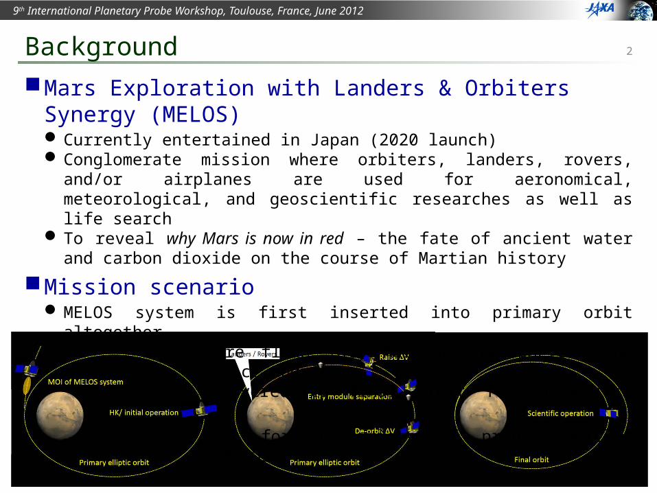
Mars Exploration with Landers & Orbiters Synergy (MELOS) Currently entertained in Japan (2020 launch) Conglomerate mission where orbiters, landers, rovers, and/or airplanes are used for
aeronomical, meteorological, and geoscientific researches as well as life search To reveal why Mars is now in red – the fate of ancient water and carbon dioxide on
the course of Martian history
Mission scenario MELOS system is first inserted into primary orbit altogether Entry systems are flown into Martian atmosphere using orbiter as a service module Orbiter is maneuvered to final orbit for scientific operation
→ Great potential for a variety of probe vehicles incorporated into MELOS
Background
3
9th International Planetary Probe Workshop, Toulouse, France, June 2012
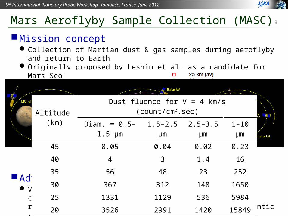
Mission concept Collection of Martian dust & gas samples during aeroflyby and return to Earth Originally proposed by Leshin et al. as a candidate for Mars Scout mission
Scenario
Advantages Valuable geological and aeronomical information on climatic vicissitude of Mars may
be obtained at reasonable cost (compared to SR missions using a gigantic system) Current dust models can be verified → better understanding of Martian climate Sample return allows us more detailed analysis in Earth than in-situ analysis Sample return allows us future reexamination of samples with improved instruments
Mars Aeroflyby Sample Collection (MASC)
Altitude (km)
Dust fluence for V = 4 km/s (count/cm2.sec)
Diam. = 0.5–1.5 μm 1.5–2.5 μm 2.5–3.5 μm 1–10 μm
45 0.05 0.04 0.02 0.23
40 4 3 1.4 16
35 56 48 23 252
30 367 312 148 1650
25 1331 1129 536 5984
20 3526 2991 1420 15849
4
9th International Planetary Probe Workshop, Toulouse, France, June 2012
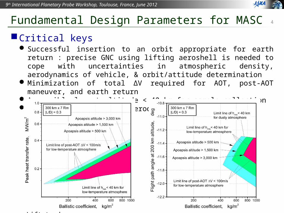
Critical keys Successful insertion to an orbit appropriate for earth return : precise GNC using
lifting aeroshell is needed to cope with uncertainties in atmospheric density, aerodynamics of vehicle, & orbit/attitude determination
Minimization of total ∆V required for AOT, post-AOT maneuver, and earth return Accessible lowest altitude < 40 km for sample collection Minimization of TPS for aerodynamic heating
Fundamental Design Parameters for MASC
Trajectory calculations
Initial orbit 300 km×7Rm alt.Periapsis altitudeof target orbit 150 km
Ballistic coefficients 100 to 1000 kg/m2
Lift-to-drag ratio – 0.3 to 0.3
5
9th International Planetary Probe Workshop, Toulouse, France, June 2012
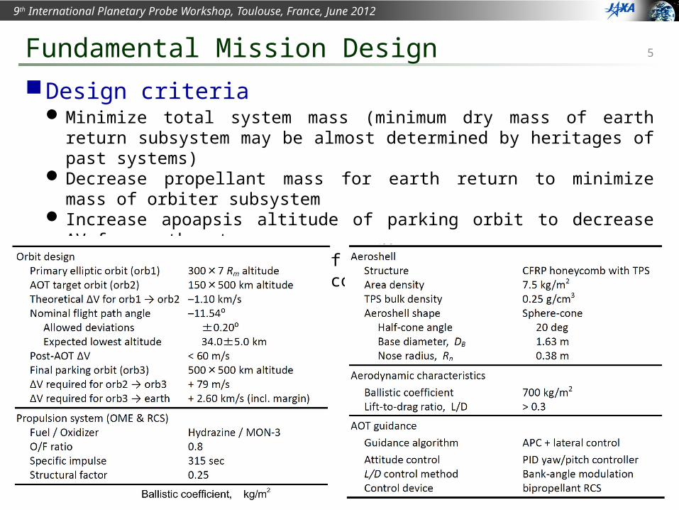
Design criteria Minimize total system mass (minimum dry mass of earth return subsystem may be
almost determined by heritages of past systems) Decrease propellant mass for earth return to minimize mass of orbiter subsystem Increase apoapsis altitude of parking orbit to decrease ∆V for earth return Decrease β for reduction of TPS mass Increase β to enlarge ATO corridor
Fundamental Mission Design
6
9th International Planetary Probe Workshop, Toulouse, France, June 2012
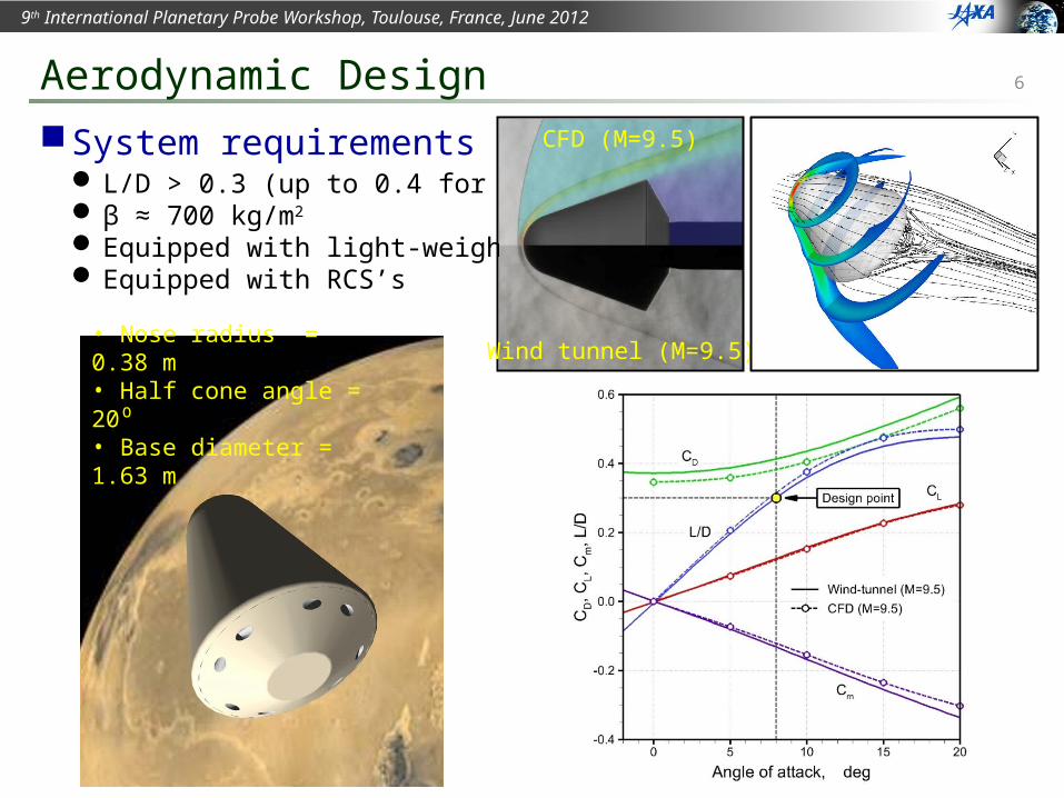
System requirements L/D > 0.3 (up to 0.4 for α < 12) β ≈ 700 kg/m2
Equipped with light-weight TPS Equipped with RCS’s
Aerodynamic Design
• Nose radius = 0.38 m• Half cone angle = 20⁰• Base diameter = 1.63 m
Wind tunnel (M=9.5)
CFD (M=9.5)
7
9th International Planetary Probe Workshop, Toulouse, France, June 2012
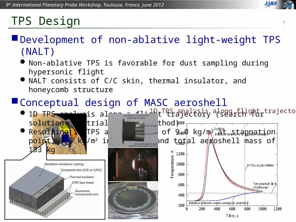
Development of non-ablative light-weight TPS (NALT) Non-ablative TPS is favorable for dust sampling during hypersonic flight NALT consists of C/C skin, thermal insulator, and honeycomb structure
Conceptual design of MASC aeroshell 1D TPS analysis along a flight trajectory (search for solutions by trial-&-error method) Resulting in TPS area density of 9.0 kg/m2 at stagnation point, 7.5 kg/m2 in average,
and total aeroshell mass of 133 kg
TPS Design
200
400
600
800
1000
1200
1400
1600
1800
0 200 400 600 800 1000 1200
Time, s
Surface
Interface between C/C & carbon aerogel
Interface between carbon aerogel & aeroshell
Temperature limitof adhesive
t=772s at alt.=200km
1D TPS analysis along flight trajectory
8
9th International Planetary Probe Workshop, Toulouse, France, June 2012
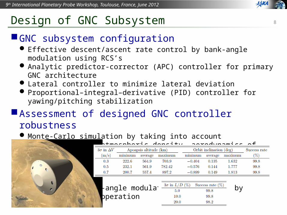
GNC subsystem configuration Effective descent/ascent rate control by bank-angle modulation using RCS’s Analytic predictor-corrector (APC) controller for primary GNC architecture Lateral controller to minimize lateral deviation Proportional–integral–derivative (PID) controller for yawing/pitching stabilization
Assessment of designed GNC controller robustness Monte-Carlo simulation by taking into account uncertainties in atmospheric density,
aerodynamics of vehicle, orbit determination, and guidance to entry I/F point Results have shown sufficient robustness of designed GNC controller Fuel used in bank-angle modulation is minimized by optimizing RCS’s operation
Design of GNC Subsystem
9
9th International Planetary Probe Workshop, Toulouse, France, June 2012
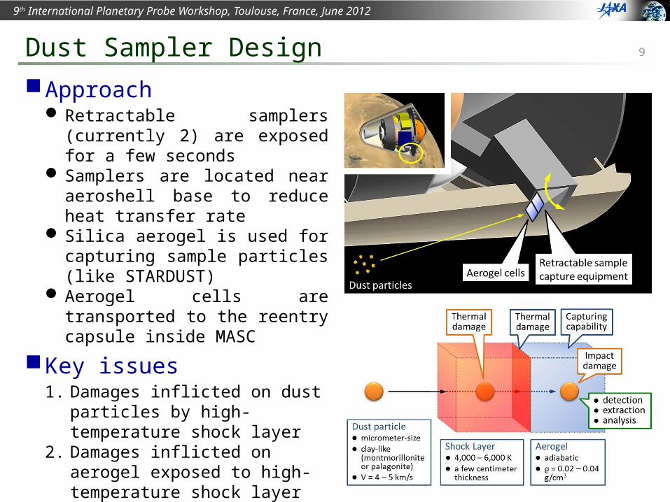
Approach Retractable samplers (currently 2) are
exposed for a few seconds Samplers are located near aeroshell
base to reduce heat transfer rate Silica aerogel is used for capturing
sample particles (like STARDUST) Aerogel cells are transported to the
reentry capsule inside MASC
Key issues1. Damages inflicted on dust particles by
high-temperature shock layer2. Damages inflicted on aerogel exposed
to high-temperature shock layer3. Dust capturing capabilities of aerogel4. damages inflicted on dust particles by
impingement5. capabilities of detecting & extracting
dust samples stuck in the aerogel
Dust Sampler Design
10
9th International Planetary Probe Workshop, Toulouse, France, June 2012
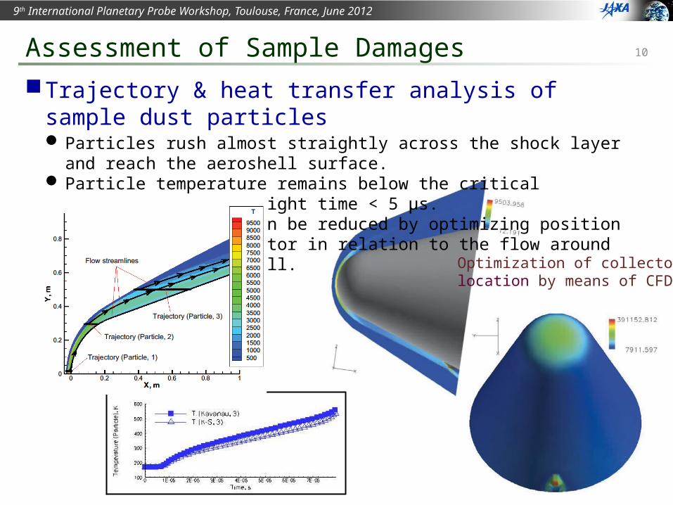
Trajectory & heat transfer analysis of sample dust particles Particles rush almost straightly across the shock layer and reach the aeroshell
surface. Particle temperature remains below the critical temperature since flight time < 5 μs. Temperature raise can be reduced by optimizing position of the sample collector in
relation to the flow around the forebody aeroshell.
Assessment of Sample Damages
Optimization of collectorlocation by means of CFD
Trajectory & HT analysis
11
9th International Planetary Probe Workshop, Toulouse, France, June 2012
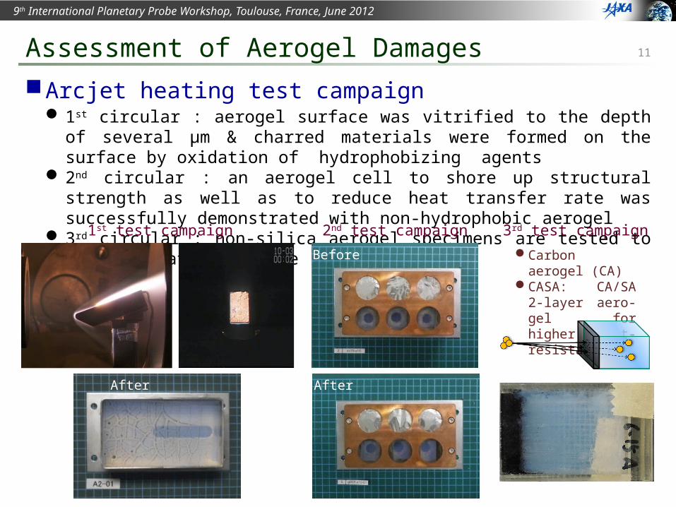
Arcjet heating test campaign 1st circular : aerogel surface was vitrified to the depth of several μm & charred
materials were formed on the surface by oxidation of hydrophobizing agents 2nd circular : an aerogel cell to shore up structural strength as well as to reduce heat
transfer rate was successfully demonstrated with non-hydrophobic aerogel 3rd circular : non-silica aerogel specimens are tested to improve heat resistance
Assessment of Aerogel Damages
Before
After
2nd test campaign1st test campaign
After
3rd test campaignCarbon aerogel (CA)CASA: CA/SA 2-layer
aero-gel for higher heat-resistance
12
9th International Planetary Probe Workshop, Toulouse, France, June 2012
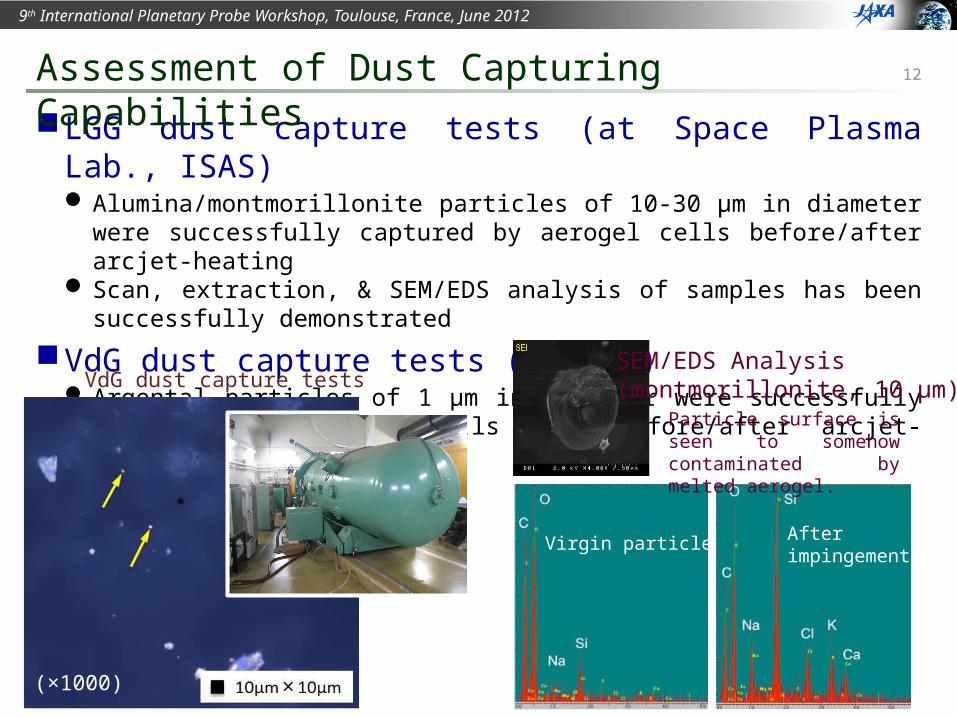
LGG dust capture tests (at Space Plasma Lab., ISAS) Alumina/montmorillonite particles of 10-30 μm in diameter were successfully
captured by aerogel cells before/after arcjet-heating Scan, extraction, & SEM/EDS analysis of samples has been successfully demonstrated
VdG dust capture tests (at HIT) Argental particles of 1 μm in diameter were successfully captured by aerogel cells
both before/after arcjet-heating.
Assessment of Dust Capturing Capabilities
(×1000)
VdG dust capture testsSEM/EDS Analysis (montmorillonite, 10 μm)
Virgin particle Afterimpingement
Particle surface is seen to somehow contaminated by melted aerogel.
13
9th International Planetary Probe Workshop, Toulouse, France, June 2012
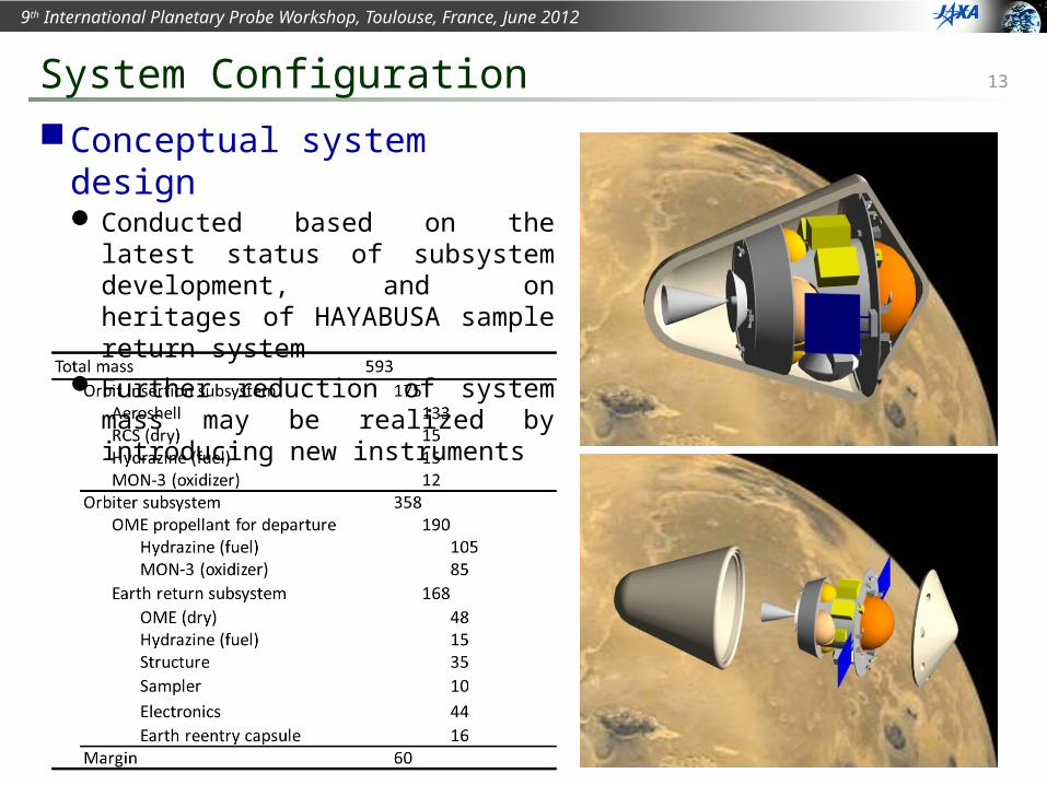
Conceptual system design Conducted based on the latest status of
subsystem development, and on heritages of HAYABUSA sample return system
Further reduction of system mass may be realized by introducing new instruments
System Configuration
14
9th International Planetary Probe Workshop, Toulouse, France, June 2012
MELOS2 mission
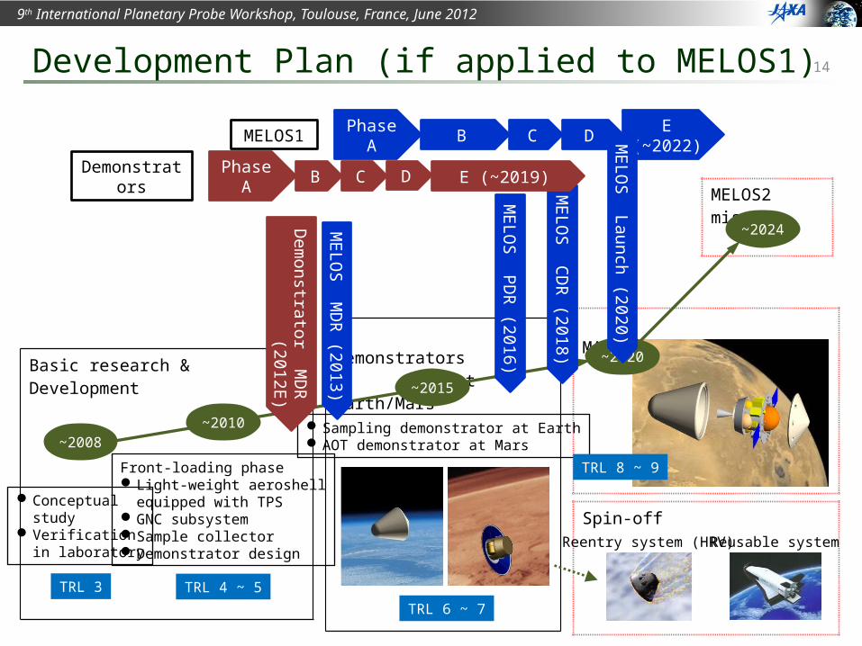
Development Plan (if applied to MELOS1)
MASC/MELOS1 mission Demonstrators at Earth/Mars
Spin-off
Basic research & Development
Sampling demonstrator at EarthAOT demonstrator at Mars
~2015
Reentry system (HRV)
~2020
TRL 6 ~ 7
TRL 8 ~ 9
Reusable system
~2010~2008
TRL 3
Front-loading phaseLight-weight aeroshell
equipped with TPSGNC subsystemSample collectorDemonstrator design
TRL 4 ~ 5
Conceptualstudy
Verificationin laboratory
MELO
S MD
R (2013)
Dem
onstrator MD
R
(2012E)
MELO
S PDR
(2016)
MELO
S CDR
(2018)
~2024
Phase A B C D E (~2022)MELOS1
Phase A B C D E (~2019)Demonstrators MELO
S Launch (2020)
15
9th International Planetary Probe Workshop, Toulouse, France, June 2012
Mars Aeroflyby Sample Collection (MASC) using AOT technologies is proposed as a part of MELOS mission
Feasibility study of MASC has been conducted The trajectory calculations have shown that a wide AOT corridor acceptable for the
state-of-the-art GNC technologies in planetary explorations can be achieved by use of a lifting aeroshell with L/D > 0.3.
Preliminary R & D of the MASC subsystems are in progress The integrated aeroshell with the TPS is designed to have a 7.5 kg/m2 area density Robustness of developed GNC controller has been demonstrated Overall examinations of dust sampling & analyzing techniques have been conducted The dust particles are expected to reach the collector across the shock layer without
fatal damages Silica aerogel cell is found to capture dust samples of sub-μm in diameter, regardless
of heat transfer from the high-temperature gases
MASC system is feasible with a minimum total mass of 600 kgMASC is also applicable to other missions, or even solely
Conclusion