Embed Size (px)
Citation preview
VERROTEC GmbH
Im Niedergarten 12a
55124 Mainz
www.verrotec.de
E-Mail: [email protected]
Tel. +49 (0) 6131 / 617 134-0
Fax +49 (0) 6131 / 617 134-144
Geschäftsführer
Dipl.-Ing. Martin Baitinger
Dr.-Ing. Lars Kützing
Prüf-, Überwachungs- und Zertifizierungsstelle (RPF14)
Content: Test Report
Project: VetroMount Top and VetroMount Side
Project number: VT 17-0682
Report: VT 17-0682 - 06
Contract: Static line load tests according to BS 6180:2011
Client: Bohle AG
Dieselstraße 10
D-42781 Haan
Date: 27/03/2019
Dr.-Ing. Mascha Baitinger (Head of Prüf-, Überwachungs- und Zertifizierungsstelle)
Dipl.-Ing. Sarah Eckhardt (Projectengineer)
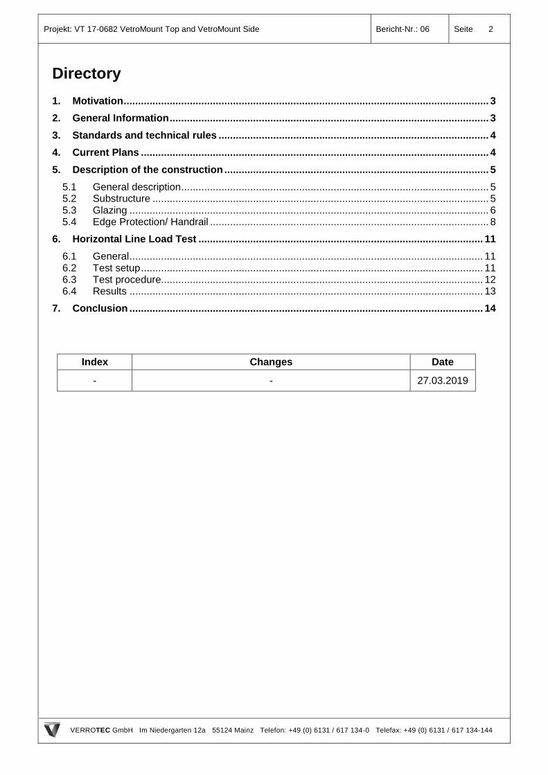
Qu
elle
: B
oh
le A
G
Projekt: VT 17-0682 VetroMount Top and VetroMount Side Bericht-Nr.: 06 Seite 2
VERROTEC GmbH Im Niedergarten 12a 55124 Mainz Telefon: +49 (0) 6131 / 617 134-0 Telefax: +49 (0) 6131 / 617 134-144
Directory
1. Motivation ............................................................................................................................... 3
2. General Information ............................................................................................................... 3
3. Standards and technical rules .............................................................................................. 4
4. Current Plans ......................................................................................................................... 4
5. Description of the construction ............................................................................................ 5
5.1 General description ........................................................................................................... 5 5.2 Substructure ..................................................................................................................... 5 5.3 Glazing ............................................................................................................................. 6 5.4 Edge Protection/ Handrail ................................................................................................. 8
6. Horizontal Line Load Test ................................................................................................... 11
6.1 General ........................................................................................................................... 11 6.2 Test setup ....................................................................................................................... 11 6.3 Test procedure................................................................................................................ 12 6.4 Results ........................................................................................................................... 13
7. Conclusion ........................................................................................................................... 14
Index Changes Date
- - 27.03.2019
Projekt: VT 17-0682 VetroMount Top and VetroMount Side Bericht-Nr.: 06 Seite 3
VERROTEC GmbH Im Niedergarten 12a 55124 Mainz Telefon: +49 (0) 6131 / 617 134-0 Telefax: +49 (0) 6131 / 617 134-144
1. Motivation
The company VERROTEC GmbH located in Mainz (Germany) was assigned by the company Bohle
AG located in D-42781 Haan to verify the guardrail effect of the balustrade system VetroMount Top
and VetroMount Side by load testing to allow the balustrade system to be classified for use in
accordance with BS 6180:2011 Barriers in and about buildings.
In this test report the relevant glass formats with their direct glazing of the substructure are evaluated
under horizontal line loading.
Subject of this report is the resistance of the balustrade system under static line loads.
A transfer of the results of this test report is not permitted, unless within the scope of this report.
2. General Information
Material compatibilities are to be verified when using different plastic materials (silicon, PVB,
etc.).
Corrosion of metallic materials has to be prevented by suitable means (e.g. different alloy choice,
coating, prevention of contact corrosion, constructive means, etc.)
Due to material and production related nickel sulphide inclusion, tempered glass is susceptible
to spontaneous breakage of glass. We recommend the general use of tempered glass with Heat
Soak Test. Due to the additional Heat Soak Test the risk of glass breakage due to nickel sulphide
inclusion is considerably minimized.
A constraint-free bearing of the glass is to be ensured.
Contact between metal and glass or glass and glass have to be avoided permanently.
In case of glass breakage the concerned areas are to be secured, the broken glass panes are
to be replaced immediately.
This document is only valid for the tested glazing system. The results of this document are only
valid, if the boundary conditions defined in this document are provided on-site. This is to be
verified on-site.
This document is to be published unabridged; partial publication requires the permission of
Verrotec GmbH.
A transfer of the results on other positions and/or systems is not allowed unless described within
this document.
The company VERROTEC GmbH in Mainz, Germany, takes responsibility only for the appraised
construction parts under the described preconditions. If there are any changes or discrepancies,
we demand notification.
Projekt: VT 17-0682 VetroMount Top and VetroMount Side Bericht-Nr.: 06 Seite 4
VERROTEC GmbH Im Niedergarten 12a 55124 Mainz Telefon: +49 (0) 6131 / 617 134-0 Telefax: +49 (0) 6131 / 617 134-144
3. Standards and technical rules
[1] BS 6180:2011 Barriers in and about buildings – Code of practice
4. Current Plans
The following current plans are the basis of this document:
[2] Profile: Pattern of drilling Topmount / Pattern of drilling Sidemount - dwg.no.: 0003953 from
22.05.2018 (3 sheets) Index 00-D.
[3] Handrail: BO_5215248 from 17.09.2018.
[4] Edge protection: BO_5215257 from 17.09.2018.
[5] Installation drawing VetroMount.
Projekt: VT 17-0682 VetroMount Top and VetroMount Side Bericht-Nr.: 06 Seite 5
VERROTEC GmbH Im Niedergarten 12a 55124 Mainz Telefon: +49 (0) 6131 / 617 134-0 Telefax: +49 (0) 6131 / 617 134-144
5. Description of the construction
5.1 General description
The glass for the guardrail system VetroMount Top and VetroMount Side consists either of monolithic
thermally toughened safety glass (TSG) or of a laminated glass consisting of thermally toughened
safety glass with at least 0.76 mm of polyvinyl butyral interlayer. The glass is clamped into a
supporting profile made of aluminium (EN AW 6063 T66).
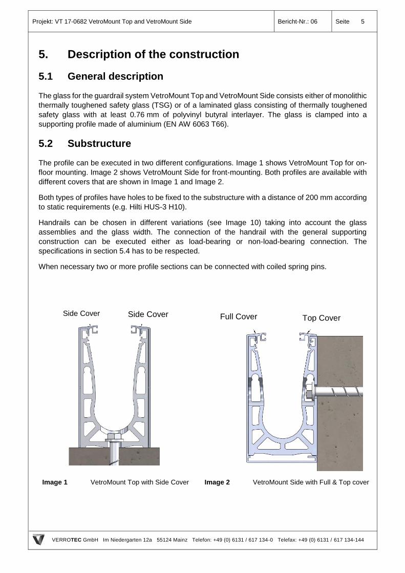
5.2 Substructure
The profile can be executed in two different configurations. Image 1 shows VetroMount Top for on-
floor mounting. Image 2 shows VetroMount Side for front-mounting. Both profiles are available with
different covers that are shown in Image 1 and Image 2.
Both types of profiles have holes to be fixed to the substructure with a distance of 200 mm according
to static requirements (e.g. Hilti HUS-3 H10).
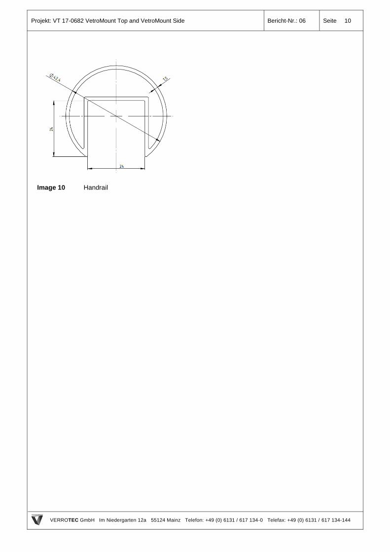
Handrails can be chosen in different variations (see Image 10) taking into account the glass
assemblies and the glass width. The connection of the handrail with the general supporting
construction can be executed either as load-bearing or non-load-bearing connection. The
specifications in section 5.4 has to be respected.
When necessary two or more profile sections can be connected with coiled spring pins.
Image 1 VetroMount Top with Side Cover
Image 2 VetroMount Side with Full & Top cover
Side Cover Side Cover Full Cover Top Cover
Projekt: VT 17-0682 VetroMount Top and VetroMount Side Bericht-Nr.: 06 Seite 6
VERROTEC GmbH Im Niedergarten 12a 55124 Mainz Telefon: +49 (0) 6131 / 617 134-0 Telefax: +49 (0) 6131 / 617 134-144
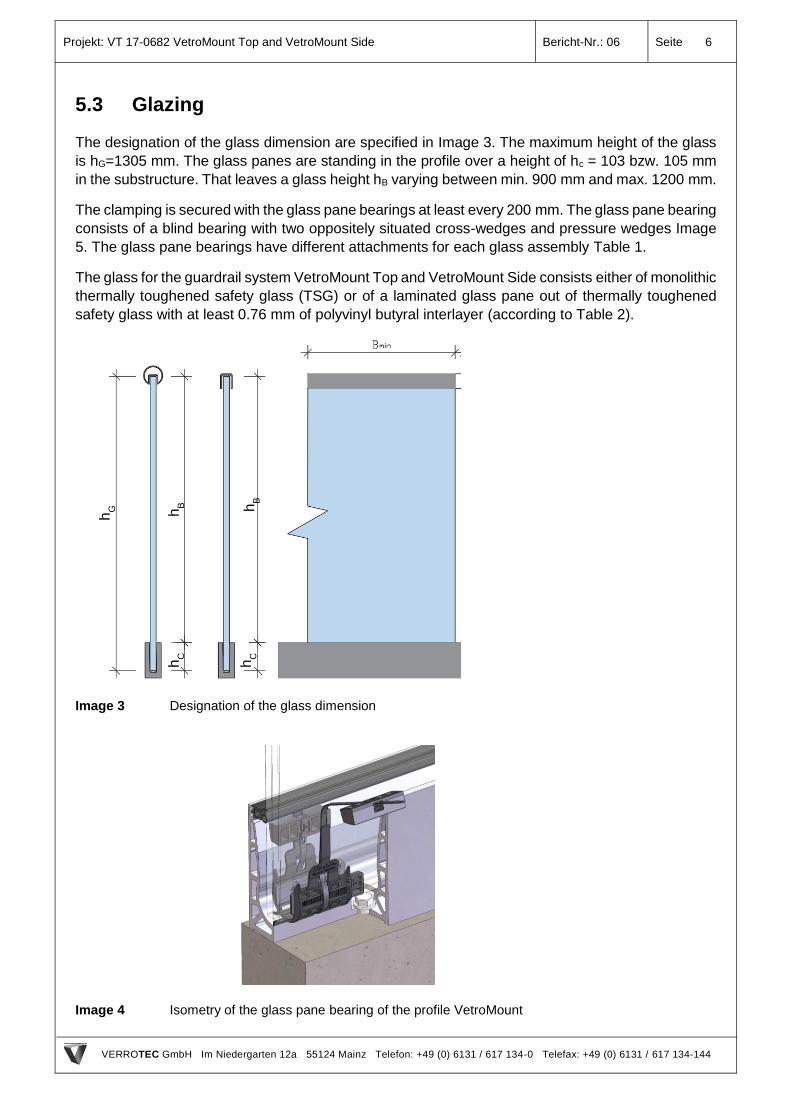
5.3 Glazing
The designation of the glass dimension are specified in Image 3. The maximum height of the glass
is hG=1305 mm. The glass panes are standing in the profile over a height of hc = 103 bzw. 105 mm
in the substructure. That leaves a glass height hB varying between min. 900 mm and max. 1200 mm.
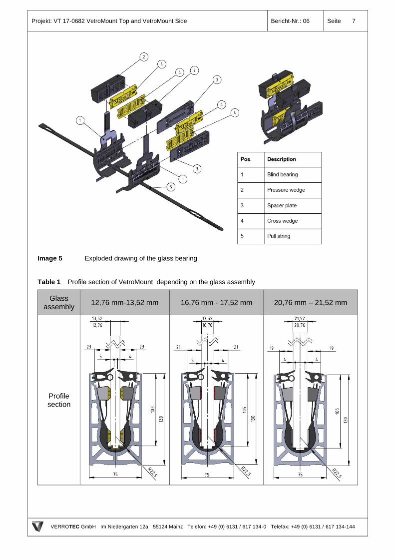
The clamping is secured with the glass pane bearings at least every 200 mm. The glass pane bearing
consists of a blind bearing with two oppositely situated cross-wedges and pressure wedges Image
5. The glass pane bearings have different attachments for each glass assembly Table 1.
The glass for the guardrail system VetroMount Top and VetroMount Side consists either of monolithic
thermally toughened safety glass (TSG) or of a laminated glass pane out of thermally toughened
safety glass with at least 0.76 mm of polyvinyl butyral interlayer (according to Table 2).
Image 3 Designation of the glass dimension
Image 4 Isometry of the glass pane bearing of the profile VetroMount
hC
hB
hC
hG hB
Projekt: VT 17-0682 VetroMount Top and VetroMount Side Bericht-Nr.: 06 Seite 7
VERROTEC GmbH Im Niedergarten 12a 55124 Mainz Telefon: +49 (0) 6131 / 617 134-0 Telefax: +49 (0) 6131 / 617 134-144
Image 5 Exploded drawing of the glass bearing
Table 1 Profile section of VetroMount depending on the glass assembly
Glass assembly
12,76 mm-13,52 mm 16,76 mm - 17,52 mm 20,76 mm – 21,52 mm
Profile section
Projekt: VT 17-0682 VetroMount Top and VetroMount Side Bericht-Nr.: 06 Seite 8
VERROTEC GmbH Im Niedergarten 12a 55124 Mainz Telefon: +49 (0) 6131 / 617 134-0 Telefax: +49 (0) 6131 / 617 134-144
Table 2 Product standards of the glass
Product Product
standard
Compliance certificate
Thermally toughened soda
lime silicate safety glass
DIN EN 12150-2 DCM (declaration of conformity by manufacturer)
Laminated safety glass DIN EN 14449 DCM (declaration of conformity by manufacturer)
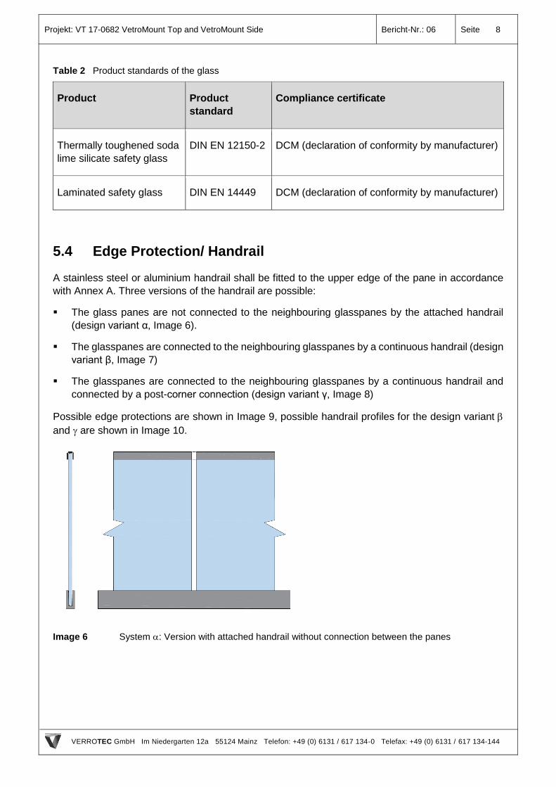
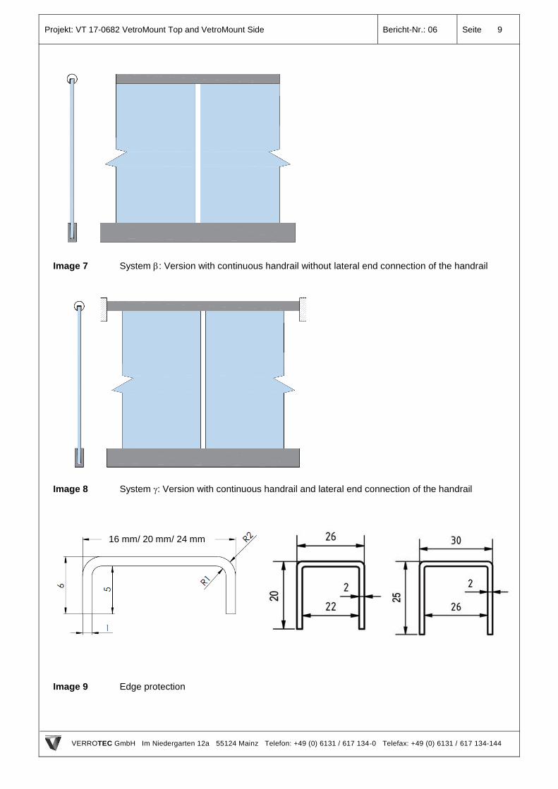
5.4 Edge Protection/ Handrail
A stainless steel or aluminium handrail shall be fitted to the upper edge of the pane in accordance
with Annex A. Three versions of the handrail are possible:
The glass panes are not connected to the neighbouring glasspanes by the attached handrail
(design variant α, Image 6).
The glasspanes are connected to the neighbouring glasspanes by a continuous handrail (design
variant β, Image 7)
The glasspanes are connected to the neighbouring glasspanes by a continuous handrail and
connected by a post-corner connection (design variant γ, Image 8)
Possible edge protections are shown in Image 9, possible handrail profiles for the design variant
and are shown in Image 10.
Image 6 System : Version with attached handrail without connection between the panes
Projekt: VT 17-0682 VetroMount Top and VetroMount Side Bericht-Nr.: 06 Seite 9
VERROTEC GmbH Im Niedergarten 12a 55124 Mainz Telefon: +49 (0) 6131 / 617 134-0 Telefax: +49 (0) 6131 / 617 134-144
Image 7 System : Version with continuous handrail without lateral end connection of the handrail
Image 8 System : Version with continuous handrail and lateral end connection of the handrail
Image 9 Edge protection
16 mm/ 20 mm/ 24 mm
Projekt: VT 17-0682 VetroMount Top and VetroMount Side Bericht-Nr.: 06 Seite 10
VERROTEC GmbH Im Niedergarten 12a 55124 Mainz Telefon: +49 (0) 6131 / 617 134-0 Telefax: +49 (0) 6131 / 617 134-144
Image 10 Handrail
Projekt: VT 17-0682 VetroMount Top and VetroMount Side Bericht-Nr.: 06 Seite 11
VERROTEC GmbH Im Niedergarten 12a 55124 Mainz Telefon: +49 (0) 6131 / 617 134-0 Telefax: +49 (0) 6131 / 617 134-144
6. Horizontal Line Load Test
6.1 General
The guardrail function of the system is verified taking into account the regulation for load testing of
BS 1680 [1].
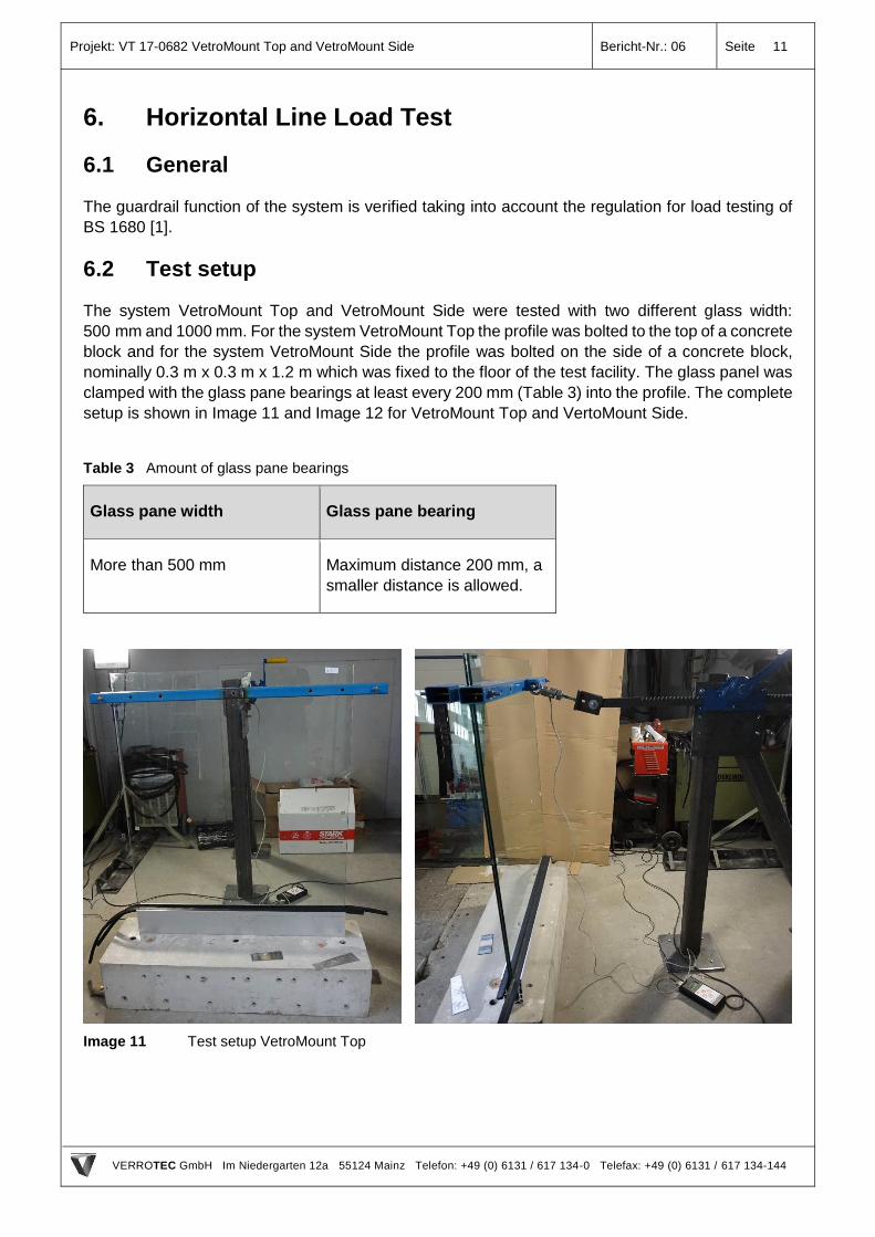
6.2 Test setup
The system VetroMount Top and VetroMount Side were tested with two different glass width:
500 mm and 1000 mm. For the system VetroMount Top the profile was bolted to the top of a concrete
block and for the system VetroMount Side the profile was bolted on the side of a concrete block,
nominally 0.3 m x 0.3 m x 1.2 m which was fixed to the floor of the test facility. The glass panel was
clamped with the glass pane bearings at least every 200 mm (Table 3) into the profile. The complete
setup is shown in Image 11 and Image 12 for VetroMount Top and VertoMount Side.
Table 3 Amount of glass pane bearings
Glass pane width Glass pane bearing
More than 500 mm Maximum distance 200 mm, a
smaller distance is allowed.
Image 11 Test setup VetroMount Top
Projekt: VT 17-0682 VetroMount Top and VetroMount Side Bericht-Nr.: 06 Seite 12
VERROTEC GmbH Im Niedergarten 12a 55124 Mainz Telefon: +49 (0) 6131 / 617 134-0 Telefax: +49 (0) 6131 / 617 134-144
Image 12 Test setup VetroMount Side
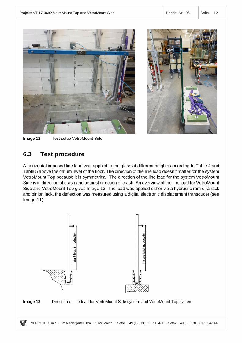
6.3 Test procedure
A horizontal imposed line load was applied to the glass at different heights according to Table 4 and
Table 5 above the datum level of the floor. The direction of the line load doesn’t matter for the system
VetroMount Top because it is symmetrical. The direction of the line load for the system VetroMount
Side is in direction of crash and against direction of crash. An overview of the line load for VetroMount
Side and VetroMount Top gives Image 13. The load was applied either via a hydraulic ram or a rack
and pinion jack, the deflection was measured using a digital electronic displacement transducer (see
Image 11).
Image 13 Direction of line load for VertoMount Side system and VertoMount Top system
Projekt: VT 17-0682 VetroMount Top and VetroMount Side Bericht-Nr.: 06 Seite 13
VERROTEC GmbH Im Niedergarten 12a 55124 Mainz Telefon: +49 (0) 6131 / 617 134-0 Telefax: +49 (0) 6131 / 617 134-144
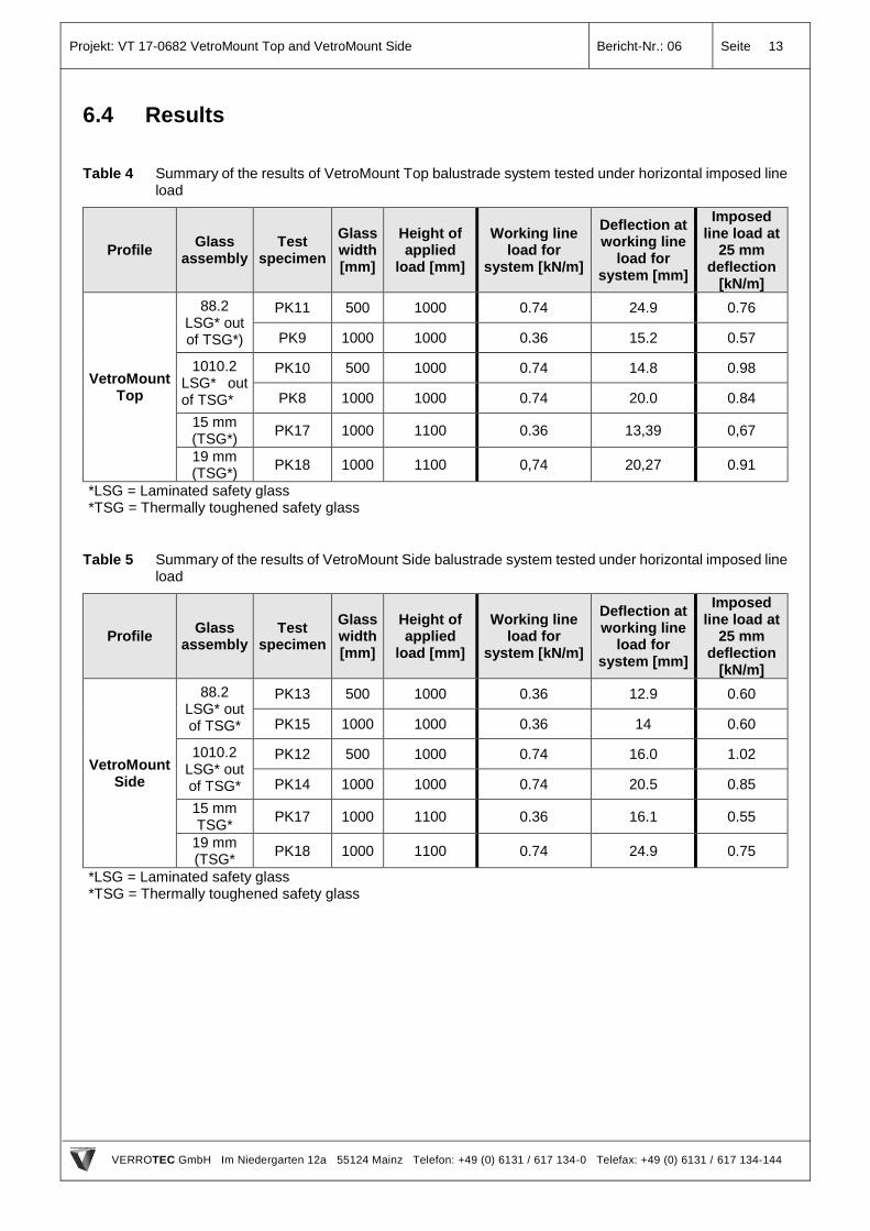
6.4 Results
Table 4 Summary of the results of VetroMount Top balustrade system tested under horizontal imposed line load
Profile Glass
assembly Test
specimen
Glass width [mm]
Height of applied
load [mm]
Working line load for
system [kN/m]
Deflection at working line
load for system [mm]
Imposed line load at
25 mm deflection
[kN/m]
VetroMount Top
88.2 LSG* out of TSG*)
PK11 500 1000 0.74 24.9 0.76
PK9 1000 1000 0.36 15.2 0.57
1010.2 LSG* out of TSG*
PK10 500 1000 0.74 14.8 0.98
PK8 1000 1000 0.74 20.0 0.84
15 mm (TSG*)
PK17 1000 1100 0.36 13,39 0,67
19 mm (TSG*)
PK18 1000 1100 0,74 20,27 0.91
*LSG = Laminated safety glass
*TSG = Thermally toughened safety glass
Table 5 Summary of the results of VetroMount Side balustrade system tested under horizontal imposed line load
Profile Glass
assembly Test
specimen
Glass width [mm]
Height of applied
load [mm]
Working line load for
system [kN/m]
Deflection at working line
load for system [mm]
Imposed line load at
25 mm deflection
[kN/m]
VetroMount Side
88.2 LSG* out of TSG*
PK13 500 1000 0.36 12.9 0.60
PK15 1000 1000 0.36 14 0.60
1010.2 LSG* out of TSG*
PK12 500 1000 0.74 16.0 1.02
PK14 1000 1000 0.74 20.5 0.85
15 mm TSG*
PK17 1000 1100 0.36 16.1 0.55
19 mm (TSG*
PK18 1000 1100 0.74 24.9 0.75
*LSG = Laminated safety glass
*TSG = Thermally toughened safety glass
Projekt: VT 17-0682 VetroMount Top and VetroMount Side Bericht-Nr.: 06 Seite 14
VERROTEC GmbH Im Niedergarten 12a 55124 Mainz Telefon: +49 (0) 6131 / 617 134-0 Telefax: +49 (0) 6131 / 617 134-144
7. Conclusion
The company VERROTEC GmbH located in Mainz (Germany) was assigned by the company Bohle
AG located in D-42781 Haan to verify the guardrail effect of the balustrade system VetroMount Top
and VetroMount Side by load testing to allow the balustrade system to be classified for use in
accordance with BS 6180:2011 Barriers in and about buildings.
The following Table 6 and Table 7 show an overview of the possible installation situations.
Projekt: VT 17-0682 VetroMount Top and VetroMount Side Bericht-Nr.: 06 Seite 15
VERROTEC GmbH Im Niedergarten 12a 55124 Mainz Telefon: +49 (0) 6131 / 617 134-0 Telefax: +49 (0) 6131 / 617 134-144
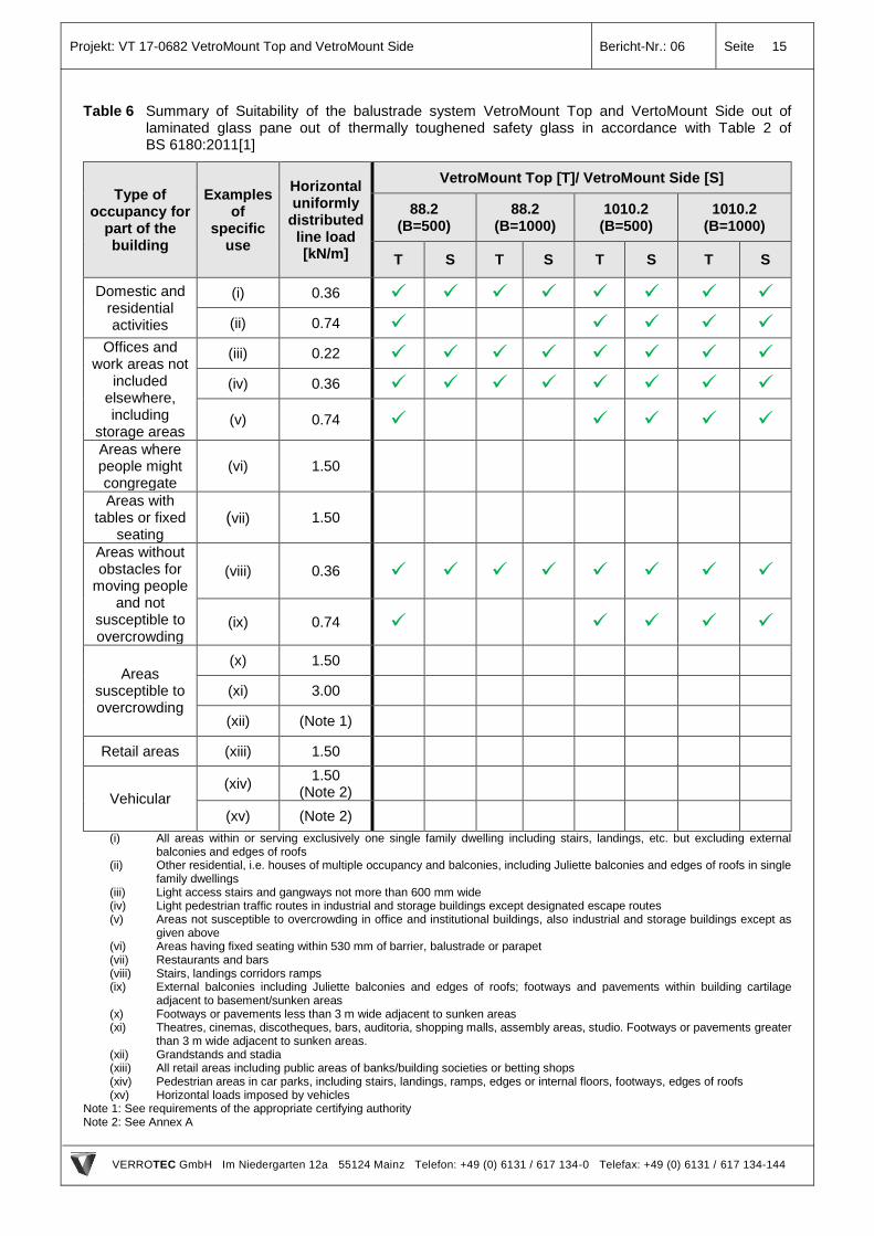
Table 6 Summary of Suitability of the balustrade system VetroMount Top and VertoMount Side out of laminated glass pane out of thermally toughened safety glass in accordance with Table 2 of BS 6180:2011[1]
Type of occupancy for
part of the building
Examples of
specific use
Horizontal uniformly
distributed line load [kN/m]
VetroMount Top [T]/ VetroMount Side [S]
88.2 (B=500)
88.2 (B=1000)
1010.2 (B=500)
1010.2 (B=1000)
T S T S T S T S
Domestic and residential activities
(i) 0.36
(ii) 0.74
Offices and work areas not
included elsewhere, including
storage areas
(iii) 0.22
(iv) 0.36
(v) 0.74
Areas where people might congregate
(vi) 1.50
Areas with tables or fixed
seating (vii) 1.50
Areas without obstacles for
moving people and not
susceptible to overcrowding
(viii) 0.36
(ix) 0.74
Areas susceptible to overcrowding
(x) 1.50
(xi) 3.00
(xii) (Note 1)
Retail areas (xiii) 1.50
Vehicular (xiv)
1.50 (Note 2)
(xv) (Note 2)
(i) All areas within or serving exclusively one single family dwelling including stairs, landings, etc. but excluding external balconies and edges of roofs
(ii) Other residential, i.e. houses of multiple occupancy and balconies, including Juliette balconies and edges of roofs in single family dwellings
(iii) Light access stairs and gangways not more than 600 mm wide (iv) Light pedestrian traffic routes in industrial and storage buildings except designated escape routes (v) Areas not susceptible to overcrowding in office and institutional buildings, also industrial and storage buildings except as
given above (vi) Areas having fixed seating within 530 mm of barrier, balustrade or parapet (vii) Restaurants and bars (viii) Stairs, landings corridors ramps (ix) External balconies including Juliette balconies and edges of roofs; footways and pavements within building cartilage
adjacent to basement/sunken areas (x) Footways or pavements less than 3 m wide adjacent to sunken areas (xi) Theatres, cinemas, discotheques, bars, auditoria, shopping malls, assembly areas, studio. Footways or pavements greater
than 3 m wide adjacent to sunken areas. (xii) Grandstands and stadia (xiii) All retail areas including public areas of banks/building societies or betting shops (xiv) Pedestrian areas in car parks, including stairs, landings, ramps, edges or internal floors, footways, edges of roofs (xv) Horizontal loads imposed by vehicles
Note 1: See requirements of the appropriate certifying authority Note 2: See Annex A
Projekt: VT 17-0682 VetroMount Top and VetroMount Side Bericht-Nr.: 06 Seite 16
VERROTEC GmbH Im Niedergarten 12a 55124 Mainz Telefon: +49 (0) 6131 / 617 134-0 Telefax: +49 (0) 6131 / 617 134-144
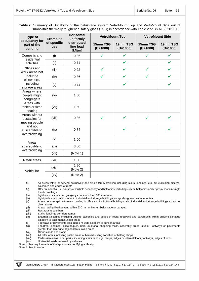
Table 7 Summary of Suitability of the balustrade system VetroMount Top and VertoMount Side out of monolithic thermally toughened safety glass (TSG) in accordance with Table 2 of BS 6180:2011[1]
Type of occupancy for
part of the building
Examples of specific
use
Horizontal uniformly
distributed line load [kN/m]
VetroMount Top VetroMount Side
15mm TSG (B=1000)
19mm TSG (B=1000)
15mm TSG (B=1000)
19mm TSG (B=1000)
Domestic and residential activities
(i) 0.36
(ii) 0.74
Offices and work areas not
included elsewhere, including
storage areas
(iii) 0.22
(iv) 0.36
(v) 0.74
Areas where people might congregate
(vi) 1.50
Areas with tables or fixed
seating (vii) 1.50
Areas without obstacles for
moving people and not
susceptible to overcrowding
(viii) 0.36
(ix) 0.74
Areas susceptible to overcrowding
(x) 1.50
(xi) 3.00
(xii) (Note 1)
Retail areas (xiii) 1.50
Vehicular (xiv)
1.50 (Note 2)
(xv) (Note 2)
(i) All areas within or serving exclusively one single family dwelling including stairs, landings, etc. but excluding external
balconies and edges of roofs (ii) Other residential, i.e. houses of multiple occupancy and balconies, including Juliette balconies and edges of roofs in single
family dwellings (iii) Light access stairs and gangways not more than 600 mm wide (iv) Light pedestrian traffic routes in industrial and storage buildings except designated escape routes (v) Areas not susceptible to overcrowding in office and institutional buildings, also industrial and storage buildings except as
given above (vi) Areas having fixed seating within 530 mm of barrier, balustrade or parapet (vii) Restaurants and bars (viii) Stairs, landings corridors ramps (ix) External balconies including Juliette balconies and edges of roofs; footways and pavements within building cartilage
adjacent to basement/sunken areas (x) Footways or pavements less than 3 m wide adjacent to sunken areas (xi) Theatres, cinemas, discotheques, bars, auditoria, shopping malls, assembly areas, studio. Footways or pavements
greater than 3 m wide adjacent to sunken areas. (xii) Grandstands and stadia (xiii) All retail areas including public areas of banks/building societies or betting shops (xiv) Pedestrian areas in car parks, including stairs, landings, ramps, edges or internal floors, footways, edges of roofs (xv) Horizontal loads imposed by vehicles
Note 1: See requirements of the appropriate certifying authority Note 2: See Annex A
VERROTEC GmbH Im Niedergarten 12a 55124 Mainz www.verrotec.de
Structural glass design | Steel constructions | Façades | Planning of structural framework | Expertise | Test laboratory
Tel. +49 (0) 6131 / 617 134-0 Fax +49 (0) 6131 / 617 134-144 E-Mail [email protected]
CEO : Dipl.-Ing. Martin Baitinger Dr.-Ing. Lars Kützing
Engineering office for structural glass design | Facades | Steel constructions
Content: Test Report
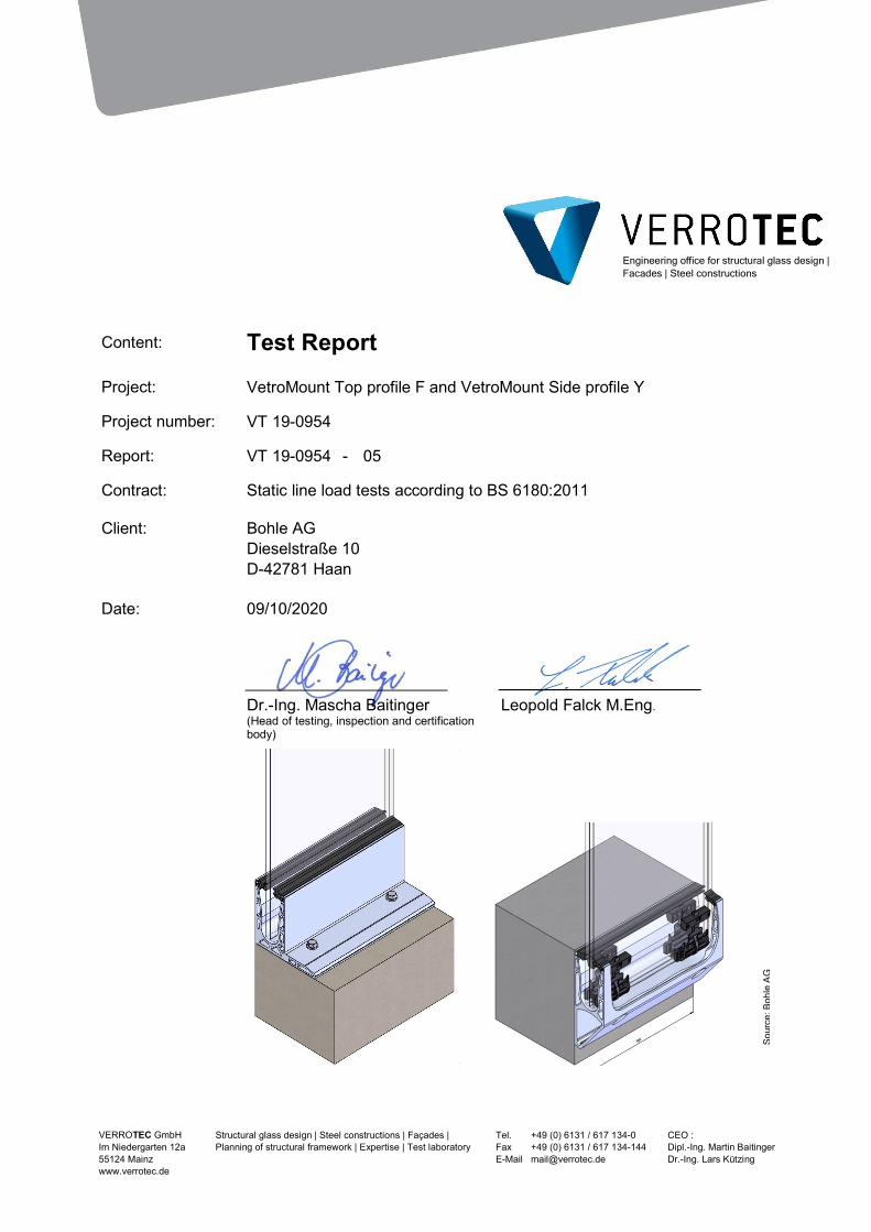
Project: VetroMount Top profile F and VetroMount Side profile Y
Project number: VT 19-0954
Report: VT 19-0954 - 05
Contract: Static line load tests according to BS 6180:2011
Client: Bohle AG Dieselstraße 10 D-42781 Haan
Date: 09/10/2020
Dr.-Ing. Mascha Baitinger (Head of testing, inspection and certification body)
Leopold Falck M.Eng.
Sou
rce:
Boh
le A
G
Project: VT 19-0954 VetroMount Top profile F and VetroMount Side profile Y – Test Report
Report : 05 Page 2
VERROTEC GmbH Im Niedergarten 12a 55124 Mainz Telefon: +49 (0) 6131 / 617 134-0 Telefax: +49 (0) 6131 / 617 134-144
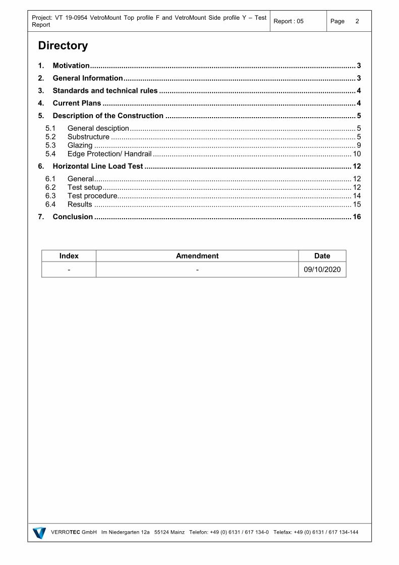
Directory
1. Motivation ............................................................................................................................... 3
2. General Information ............................................................................................................... 3
3. Standards and technical rules .............................................................................................. 4
4. Current Plans ......................................................................................................................... 4
5. Description of the Construction ........................................................................................... 5
5.1 General desciption ............................................................................................................ 5 5.2 Substructure ..................................................................................................................... 5 5.3 Glazing ............................................................................................................................. 9 5.4 Edge Protection/ Handrail ............................................................................................... 10
6. Horizontal Line Load Test ................................................................................................... 12
6.1 General ........................................................................................................................... 12 6.2 Test setup ....................................................................................................................... 12 6.3 Test procedure................................................................................................................ 14 6.4 Results ........................................................................................................................... 15
7. Conclusion ........................................................................................................................... 16
Index Amendment Date
- - 09/10/2020
Project: VT 19-0954 VetroMount Top profile F and VetroMount Side profile Y – Test Report
Report : 05 Page 3
VERROTEC GmbH Im Niedergarten 12a 55124 Mainz Telefon: +49 (0) 6131 / 617 134-0 Telefax: +49 (0) 6131 / 617 134-144
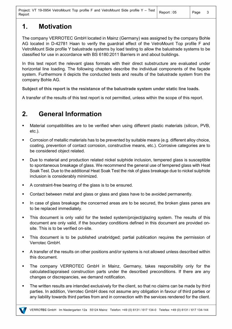
1. Motivation
The company VERROTEC GmbH located in Mainz (Germany) was assigned by the company Bohle AG located in D-42781 Haan to verify the guardrail effect of the VetroMount Top profile F and VetroMount Side profile Y balustrade systems by load testing to allow the balustrade systems to be classified for use in accordance with BS 6180:2011 Barriers in and about buildings.
In this test report the relevant glass formats with their direct substructure are evaluated under horizontal line loading. The following chapters describe the individual components of the façade system. Furthermore it depicts the conducted tests and results of the balustrade system from the company Bohle AG.
Subject of this report is the resistance of the balustrade system under static line loads.
A transfer of the results of this test report is not permitted, unless within the scope of this report.
2. General Information
Material compatibilities are to be verified when using different plastic materials (silicon, PVB, etc.).
Corrosion of metallic materials has to be prevented by suitable means (e.g. different alloy choice, coating, prevention of contact corrosion, constructive means, etc.). Corrosive categories are to be considered object related.
Due to material and production related nickel sulphide inclusion, tempered glass is susceptible to spontaneous breakage of glass. We recommend the general use of tempered glass with Heat Soak Test. Due to the additional Heat Soak Test the risk of glass breakage due to nickel sulphide inclusion is considerably minimized.
A constraint-free bearing of the glass is to be ensured.
Contact between metal and glass or glass and glass have to be avoided permanently.
In case of glass breakage the concerned areas are to be secured, the broken glass panes are to be replaced immediately.
This document is only valid for the tested system/project/glazing system. The results of this document are only valid, if the boundary conditions defined in this document are provided on-site. This is to be verified on-site.
This document is to be published unabridged; partial publication requires the permission of Verrotec GmbH.
A transfer of the results on other positions and/or systems is not allowed unless described within this document.
The company VERROTEC GmbH in Mainz, Germany, takes responsibility only for the calculated/appraised construction parts under the described preconditions. If there are any changes or discrepancies, we demand notification.
The written results are intended exclusively for the client, so that no claims can be made by third parties. In addition, Verrotec GmbH does not assume any obligation in favour of third parties or any liability towards third parties from and in connection with the services rendered for the client.
Project: VT 19-0954 VetroMount Top profile F and VetroMount Side profile Y – Test Report
Report : 05 Page 4
VERROTEC GmbH Im Niedergarten 12a 55124 Mainz Telefon: +49 (0) 6131 / 617 134-0 Telefax: +49 (0) 6131 / 617 134-144
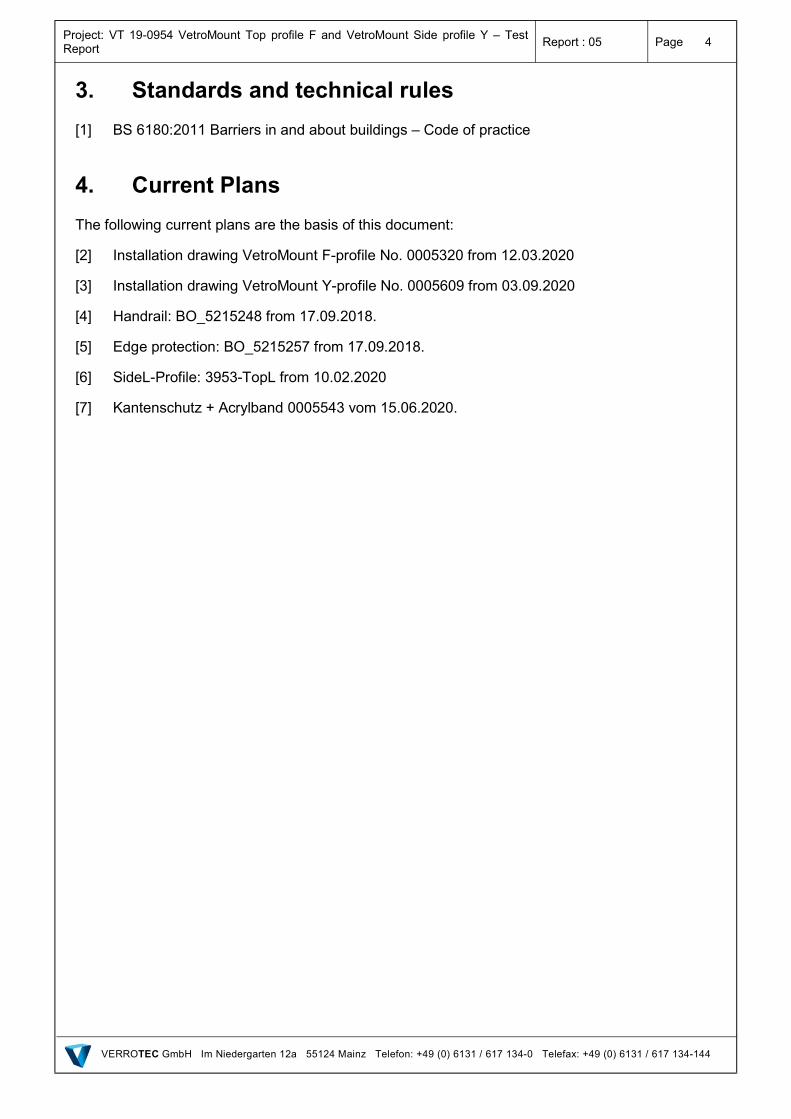
3. Standards and technical rules
[1] BS 6180:2011 Barriers in and about buildings – Code of practice
4. Current Plans
The following current plans are the basis of this document:
[2] Installation drawing VetroMount F-profile No. 0005320 from 12.03.2020
[3] Installation drawing VetroMount Y-profile No. 0005609 from 03.09.2020
[4] Handrail: BO_5215248 from 17.09.2018.
[5] Edge protection: BO_5215257 from 17.09.2018.
[6] SideL-Profile: 3953-TopL from 10.02.2020
[7] Kantenschutz + Acrylband 0005543 vom 15.06.2020.
Project: VT 19-0954 VetroMount Top profile F and VetroMount Side profile Y – Test Report
Report : 05 Page 5
VERROTEC GmbH Im Niedergarten 12a 55124 Mainz Telefon: +49 (0) 6131 / 617 134-0 Telefax: +49 (0) 6131 / 617 134-144
5. Description of the Construction
5.1 General desciption
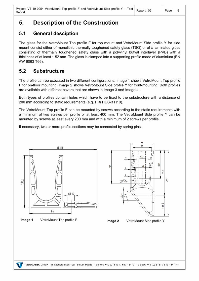
The glass for the VetroMount Top profile F for top mount and VetroMount Side profile Y for side mount consist either of monolithic thermally toughened safety glass (TSG) or of a laminated glass consisting of thermally toughened safety glass with a polyvinyl butyal interlayer (PVB) with a thickness of at least 1.52 mm. The glass is clamped into a supporting profile made of aluminium (EN AW 6063 T66).
5.2 Substructure
The profile can be executed in two different configurations. Image 1 shows VetroMount Top profile F for on-floor mounting. Image 2 shows VetroMount Side profile Y for front-mounting. Both profiles are available with different covers that are shown in Image 3 and Image 4.
Both types of profiles contain holes which have to be fixed to the substructure with a distance of 200 mm according to static requirements (e.g. Hilti HUS-3 H10).
The VetroMount Top profile F can be mounted by screws according to the static requirements with a minimum of two screws per profile or at least 400 mm. The VetroMount Side profile Y can be mounted by screws at least every 200 mm and with a minimum of 2 screws per profile.
If necessary, two or more profile sections may be connected by spring pins.
Image 1 VetroMount Top profile F
Image 2 VetroMount Side profile Y
Project: VT 19-0954 VetroMount Top profile F and VetroMount Side profile Y – Test Report
Report : 05 Page 6
VERROTEC GmbH Im Niedergarten 12a 55124 Mainz Telefon: +49 (0) 6131 / 617 134-0 Telefax: +49 (0) 6131 / 617 134-144
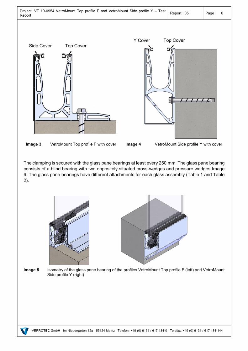
Image 3 VetroMount Top profile F with cover
Image 4 VetroMount Side profile Y with cover
The clamping is secured with the glass pane bearings at least every 250 mm. The glass pane bearing consists of a blind bearing with two oppositely situated cross-wedges and pressure wedges Image 6. The glass pane bearings have different attachments for each glass assembly (Table 1 and Table 2).
Image 5 Isometry of the glass pane bearing of the profiles VetroMount Top profile F (left) and VetroMount
Side profile Y (right)
Side Cover Top Cover Top Cover Y Cover
Project: VT 19-0954 VetroMount Top profile F and VetroMount Side profile Y – Test Report
Report : 05 Page 7
VERROTEC GmbH Im Niedergarten 12a 55124 Mainz Telefon: +49 (0) 6131 / 617 134-0 Telefax: +49 (0) 6131 / 617 134-144
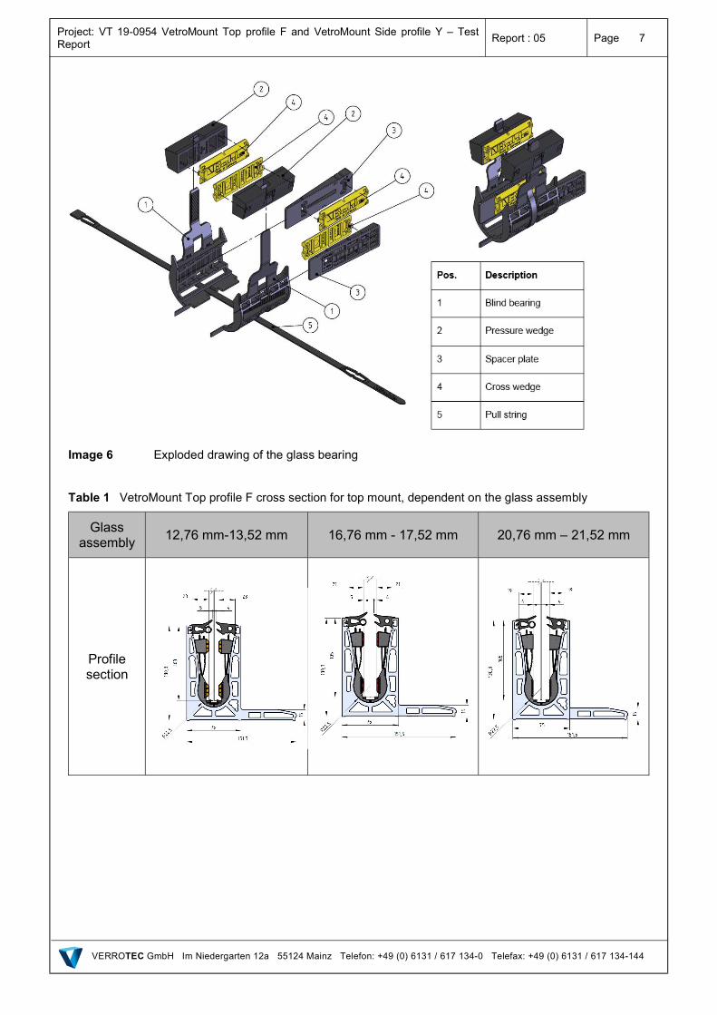
Image 6 Exploded drawing of the glass bearing
Table 1 VetroMount Top profile F cross section for top mount, dependent on the glass assembly
Glass assembly
12,76 mm-13,52 mm 16,76 mm - 17,52 mm 20,76 mm – 21,52 mm
Profile section
Project: VT 19-0954 VetroMount Top profile F and VetroMount Side profile Y – Test Report
Report : 05 Page 8
VERROTEC GmbH Im Niedergarten 12a 55124 Mainz Telefon: +49 (0) 6131 / 617 134-0 Telefax: +49 (0) 6131 / 617 134-144
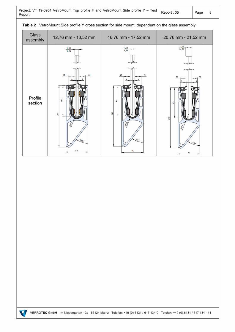
Table 2 VetroMount Side profile Y cross section for side mount, dependent on the glass assembly
Glass assembly
12,76 mm - 13,52 mm 16,76 mm - 17,52 mm 20,76 mm - 21,52 mm
Profile section
Project: VT 19-0954 VetroMount Top profile F and VetroMount Side profile Y – Test Report
Report : 05 Page 9
VERROTEC GmbH Im Niedergarten 12a 55124 Mainz Telefon: +49 (0) 6131 / 617 134-0 Telefax: +49 (0) 6131 / 617 134-144
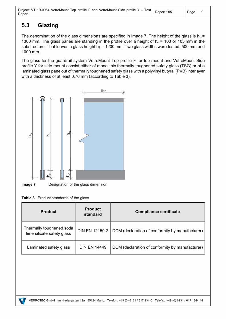
5.3 Glazing
The denomination of the glass dimensions are specified in Image 7. The height of the glass is hG = 1300 mm. The glass panes are standing in the profile over a height of hc = 103 or 105 mm in the substructure. That leaves a glass height hB = 1200 mm. Two glass widths were tested: 500 mm and 1000 mm.
The glass for the guardrail system VetroMount Top profile F for top mount and VetroMount Side profile Y for side mount consist either of monolithic thermally toughened safety glass (TSG) or of a laminated glass pane out of thermally toughened safety glass with a polyvinyl butyral (PVB) interlayer with a thickness of at least 0.76 mm (according to Table 3).
Image 7 Designation of the glass dimension
Table 3 Product standards of the glass
Product Product standard
Compliance certificate
Thermally toughened soda lime silicate safety glass
DIN EN 12150-2 DCM (declaration of conformity by manufacturer)
Laminated safety glass DIN EN 14449 DCM (declaration of conformity by manufacturer)
h C
h B
h C
h G h B
Project: VT 19-0954 VetroMount Top profile F and VetroMount Side profile Y – Test Report
Report : 05 Page 10
VERROTEC GmbH Im Niedergarten 12a 55124 Mainz Telefon: +49 (0) 6131 / 617 134-0 Telefax: +49 (0) 6131 / 617 134-144
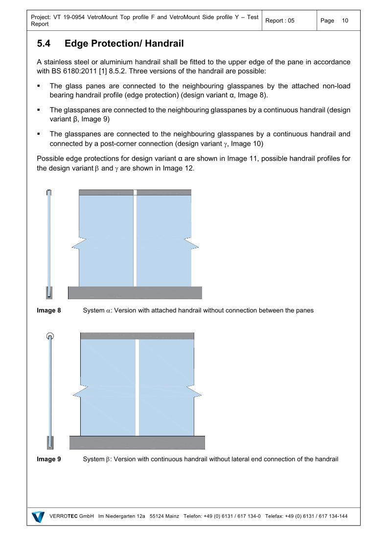
5.4 Edge Protection/ Handrail
A stainless steel or aluminium handrail shall be fitted to the upper edge of the pane in accordance with BS 6180:2011 [1] 8.5.2. Three versions of the handrail are possible:
The glass panes are connected to the neighbouring glasspanes by the attached non-load bearing handrail profile (edge protection) (design variant α, Image 8).
The glasspanes are connected to the neighbouring glasspanes by a continuous handrail (design variant β, Image 9)
The glasspanes are connected to the neighbouring glasspanes by a continuous handrail and connected by a post-corner connection (design variant , Image 10)
Possible edge protections for design variant α are shown in Image 11, possible handrail profiles for the design variant and are shown in Image 12.
Image 8 System : Version with attached handrail without connection between the panes
Image 9 System : Version with continuous handrail without lateral end connection of the handrail
Project: VT 19-0954 VetroMount Top profile F and VetroMount Side profile Y – Test Report
Report : 05 Page 11
VERROTEC GmbH Im Niedergarten 12a 55124 Mainz Telefon: +49 (0) 6131 / 617 134-0 Telefax: +49 (0) 6131 / 617 134-144
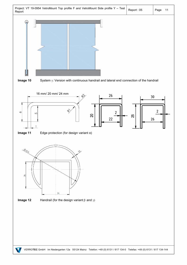
Image 10 System : Version with continuous handrail and lateral end connection of the handrail
Image 11 Edge protection (for design variant α)
Image 12 Handrail (for the design variant and
16 mm/ 20 mm/ 24 mm
Project: VT 19-0954 VetroMount Top profile F and VetroMount Side profile Y – Test Report
Report : 05 Page 12
VERROTEC GmbH Im Niedergarten 12a 55124 Mainz Telefon: +49 (0) 6131 / 617 134-0 Telefax: +49 (0) 6131 / 617 134-144
6. Horizontal Line Load Test
6.1 General
The guardrail function of the system is verified taking into account the regulation for load testing of BS 1680 [1].
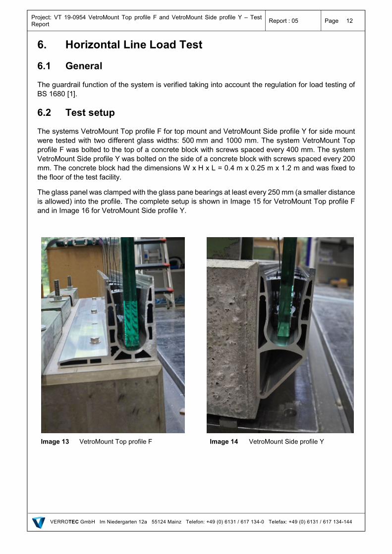
6.2 Test setup
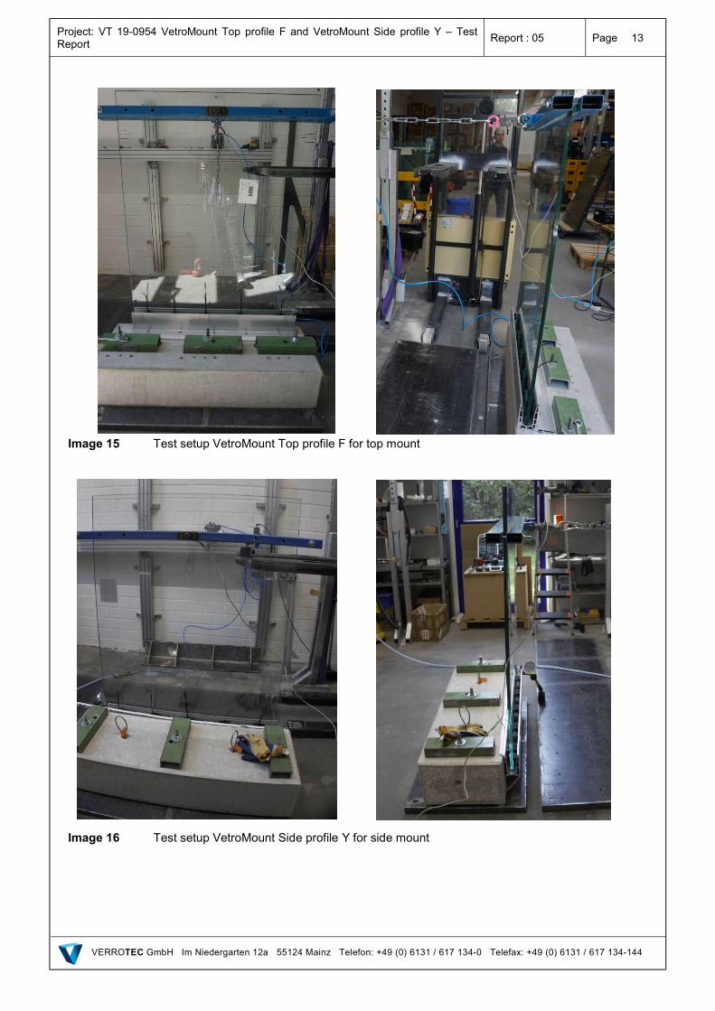
The systems VetroMount Top profile F for top mount and VetroMount Side profile Y for side mount were tested with two different glass widths: 500 mm and 1000 mm. The system VetroMount Top profile F was bolted to the top of a concrete block with screws spaced every 400 mm. The system VetroMount Side profile Y was bolted on the side of a concrete block with screws spaced every 200 mm. The concrete block had the dimensions W x H x L = 0.4 m x 0.25 m x 1.2 m and was fixed to the floor of the test facility.
The glass panel was clamped with the glass pane bearings at least every 250 mm (a smaller distance is allowed) into the profile. The complete setup is shown in Image 15 for VetroMount Top profile F and in Image 16 for VetroMount Side profile Y.
Image 13 VetroMount Top profile F
Image 14 VetroMount Side profile Y
Project: VT 19-0954 VetroMount Top profile F and VetroMount Side profile Y – Test Report
Report : 05 Page 13
VERROTEC GmbH Im Niedergarten 12a 55124 Mainz Telefon: +49 (0) 6131 / 617 134-0 Telefax: +49 (0) 6131 / 617 134-144
Image 15 Test setup VetroMount Top profile F for top mount
Image 16 Test setup VetroMount Side profile Y for side mount
Project: VT 19-0954 VetroMount Top profile F and VetroMount Side profile Y – Test Report
Report : 05 Page 14
VERROTEC GmbH Im Niedergarten 12a 55124 Mainz Telefon: +49 (0) 6131 / 617 134-0 Telefax: +49 (0) 6131 / 617 134-144
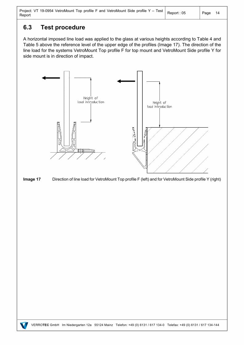
6.3 Test procedure
A horizontal imposed line load was applied to the glass at various heights according to Table 4 and Table 5 above the reference level of the upper edge of the profiles (Image 17). The direction of the line load for the systems VetroMount Top profile F for top mount and VetroMount Side profile Y for side mount is in direction of impact.
Image 17 Direction of line load for VetroMount Top profile F (left) and for VetroMount Side profile Y (right)
Project: VT 19-0954 VetroMount Top profile F and VetroMount Side profile Y – Test Report
Report : 05 Page 15
VERROTEC GmbH Im Niedergarten 12a 55124 Mainz Telefon: +49 (0) 6131 / 617 134-0 Telefax: +49 (0) 6131 / 617 134-144
6.4 Results
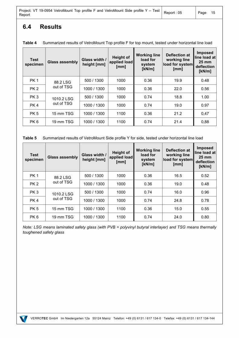
Table 4 Summarized results of VetroMount Top profile F for top mount, tested under horizontal line load
Test specimen
Glass assembly Glass width / height [mm]
Height of applied load
[mm]
Working line load for system [kN/m]
Deflection at working line
load for system [mm]
Imposed line load at
25 mm deflection
[kN/m]
PK 1 88.2 LSG out of TSG
500 / 1300 1000 0.36 19.9 0.48
PK 2 1000 / 1300 1000 0.36 22.0 0.56
PK 3 1010.2 LSG out of TSG
500 / 1300 1000 0.74 18.8 1.00
PK 4 1000 / 1300 1000 0.74 19.0 0.97
PK 5 15 mm TSG 1000 / 1300 1100 0.36 21.2 0,47
PK 6 19 mm TSG 1000 / 1300 1100 0.74 21.4 0,88
Table 5 Summarized results of VetroMount Side profile Y for side, tested under horizontal line load
Test specimen
Glass assembly Glass width / height [mm]
Height of applied load
[mm]
Working line load for system [kN/m]
Deflection at working line
load for system [mm]
Imposed line load at
25 mm deflection
[kN/m]
PK 1 88.2 LSG out of TSG
500 / 1300 1000 0.36 16.5 0.52
PK 2 1000 / 1300 1000 0.36 19.0 0.48
PK 3 1010.2 LSG out of TSG
500 / 1300 1000 0.74 16.0 0.96
PK 4 1000 / 1300 1000 0.74 24.8 0.78
PK 5 15 mm TSG 1000 / 1300 1100 0.36 15.0 0.55
PK 6 19 mm TSG 1000 / 1300 1100 0.74 24.0 0.80
Note: LSG means laminated safety glass (with PVB = polyvinyl butyral interlayer) and TSG means thermally toughened safety glass

Project: VT 19-0954 VetroMount Top profile F and VetroMount Side profile Y – Test Report
Report : 05 Page 16
VERROTEC GmbH Im Niedergarten 12a 55124 Mainz Telefon: +49 (0) 6131 / 617 134-0 Telefax: +49 (0) 6131 / 617 134-144
7. Conclusion
The company VERROTEC GmbH located in Mainz (Germany) was assigned by the company Bohle AG located in D-42781 Haan to verify the guardrail effect of the VetroMount Top profile F and VetroMount Side profile Y balustrade systems by load testing to allow the balustrade systems to be classified for use in accordance with BS 6180:2011 Barriers in and about buildings.
Subject of this report is the resistance of the balustrade system under static line loads.
The possible installation situations are given in Table 6 and Table 7.
Project: VT 19-0954 VetroMount Top profile F and VetroMount Side profile Y – Test Report
Report : 05 Page 17
VERROTEC GmbH Im Niedergarten 12a 55124 Mainz Telefon: +49 (0) 6131 / 617 134-0 Telefax: +49 (0) 6131 / 617 134-144
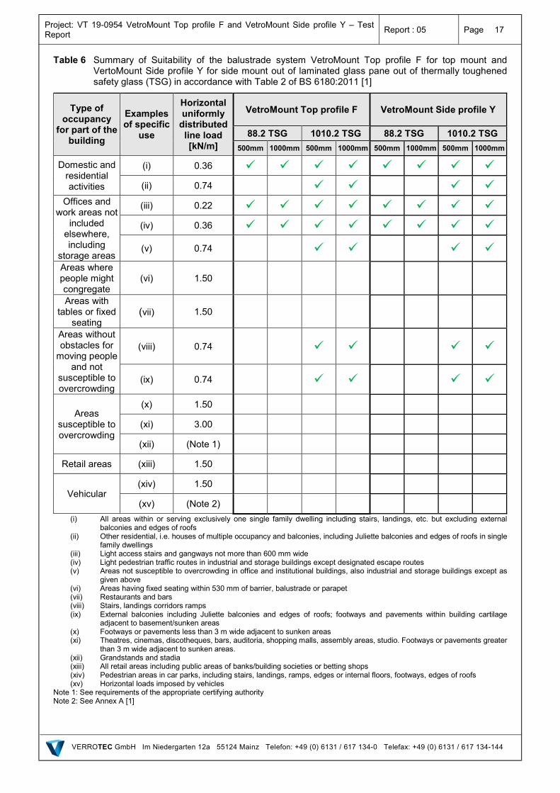
Table 6 Summary of Suitability of the balustrade system VetroMount Top profile F for top mount and VertoMount Side profile Y for side mount out of laminated glass pane out of thermally toughened safety glass (TSG) in accordance with Table 2 of BS 6180:2011 [1]
Type of occupancy
for part of the building
Examples of specific
use
Horizontal uniformly
distributed line load [kN/m]
VetroMount Top profile F VetroMount Side profile Y
88.2 TSG 1010.2 TSG 88.2 TSG 1010.2 TSG
500mm 1000mm 500mm 1000mm 500mm 1000mm 500mm 1000mm
Domestic and residential activities
(i) 0.36
(ii) 0.74
Offices and work areas not
included elsewhere, including
storage areas
(iii) 0.22
(iv) 0.36
(v) 0.74
Areas where people might congregate
(vi) 1.50
Areas with tables or fixed
seating (vii) 1.50
Areas without obstacles for
moving people and not
susceptible to overcrowding
(viii) 0.74
(ix) 0.74
Areas susceptible to overcrowding
(x) 1.50
(xi) 3.00
(xii) (Note 1)
Retail areas (xiii) 1.50
Vehicular (xiv) 1.50
(xv) (Note 2)
(i) All areas within or serving exclusively one single family dwelling including stairs, landings, etc. but excluding external balconies and edges of roofs
(ii) Other residential, i.e. houses of multiple occupancy and balconies, including Juliette balconies and edges of roofs in single family dwellings
(iii) Light access stairs and gangways not more than 600 mm wide (iv) Light pedestrian traffic routes in industrial and storage buildings except designated escape routes (v) Areas not susceptible to overcrowding in office and institutional buildings, also industrial and storage buildings except as
given above (vi) Areas having fixed seating within 530 mm of barrier, balustrade or parapet (vii) Restaurants and bars (viii) Stairs, landings corridors ramps (ix) External balconies including Juliette balconies and edges of roofs; footways and pavements within building cartilage
adjacent to basement/sunken areas (x) Footways or pavements less than 3 m wide adjacent to sunken areas (xi) Theatres, cinemas, discotheques, bars, auditoria, shopping malls, assembly areas, studio. Footways or pavements greater
than 3 m wide adjacent to sunken areas. (xii) Grandstands and stadia (xiii) All retail areas including public areas of banks/building societies or betting shops (xiv) Pedestrian areas in car parks, including stairs, landings, ramps, edges or internal floors, footways, edges of roofs (xv) Horizontal loads imposed by vehicles
Note 1: See requirements of the appropriate certifying authority Note 2: See Annex A [1]
Project: VT 19-0954 VetroMount Top profile F and VetroMount Side profile Y – Test Report
Report : 05 Page 18
VERROTEC GmbH Im Niedergarten 12a 55124 Mainz Telefon: +49 (0) 6131 / 617 134-0 Telefax: +49 (0) 6131 / 617 134-144
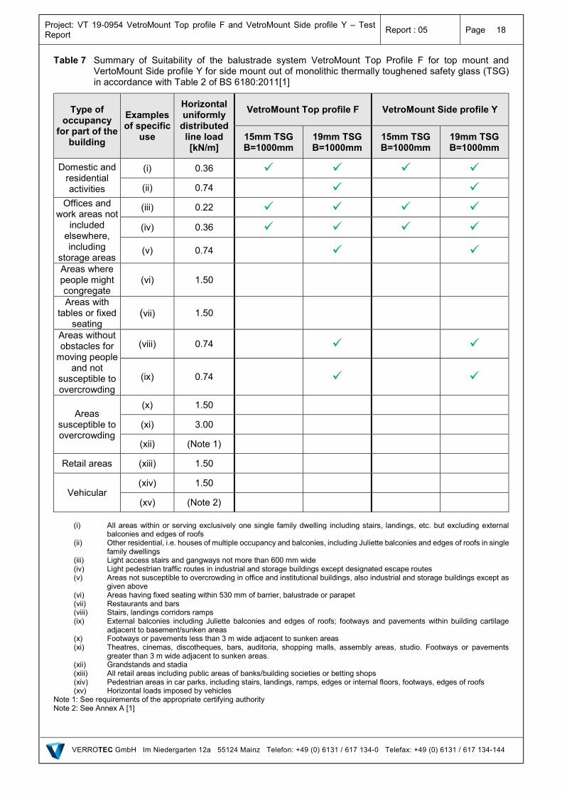
Table 7 Summary of Suitability of the balustrade system VetroMount Top Profile F for top mount and VertoMount Side profile Y for side mount out of monolithic thermally toughened safety glass (TSG) in accordance with Table 2 of BS 6180:2011[1]
Type of occupancy
for part of the building
Examples of specific
use
Horizontal uniformly
distributed line load [kN/m]
VetroMount Top profile F VetroMount Side profile Y
15mm TSG B=1000mm
19mm TSG B=1000mm
15mm TSG B=1000mm
19mm TSG B=1000mm
Domestic and residential activities
(i) 0.36
(ii) 0.74
Offices and work areas not
included elsewhere, including
storage areas
(iii) 0.22
(iv) 0.36
(v) 0.74
Areas where people might congregate
(vi) 1.50
Areas with tables or fixed
seating (vii) 1.50
Areas without obstacles for
moving people and not
susceptible to overcrowding
(viii) 0.74
(ix) 0.74
Areas susceptible to overcrowding
(x) 1.50
(xi) 3.00
(xii) (Note 1)
Retail areas (xiii) 1.50
Vehicular (xiv) 1.50
(xv) (Note 2)
(i) All areas within or serving exclusively one single family dwelling including stairs, landings, etc. but excluding external
balconies and edges of roofs (ii) Other residential, i.e. houses of multiple occupancy and balconies, including Juliette balconies and edges of roofs in single
family dwellings (iii) Light access stairs and gangways not more than 600 mm wide (iv) Light pedestrian traffic routes in industrial and storage buildings except designated escape routes (v) Areas not susceptible to overcrowding in office and institutional buildings, also industrial and storage buildings except as
given above (vi) Areas having fixed seating within 530 mm of barrier, balustrade or parapet (vii) Restaurants and bars (viii) Stairs, landings corridors ramps (ix) External balconies including Juliette balconies and edges of roofs; footways and pavements within building cartilage
adjacent to basement/sunken areas (x) Footways or pavements less than 3 m wide adjacent to sunken areas (xi) Theatres, cinemas, discotheques, bars, auditoria, shopping malls, assembly areas, studio. Footways or pavements
greater than 3 m wide adjacent to sunken areas. (xii) Grandstands and stadia (xiii) All retail areas including public areas of banks/building societies or betting shops (xiv) Pedestrian areas in car parks, including stairs, landings, ramps, edges or internal floors, footways, edges of roofs (xv) Horizontal loads imposed by vehicles
Note 1: See requirements of the appropriate certifying authority Note 2: See Annex A [1]