Embed Size (px)
Citation preview

The Design Discipline

Figure 7-1
Moving From Business Modeling Requirements to Design

Understanding the Elements of Design
Systems design discipline
Two tiers of discipline tasks
Design Activities
Support services architecture & deployment environment
Software architecture
Use case realizations
Database
System and user interfaces
System security and controls

Figure 7-3System Development Information Stored in the CASE Repository
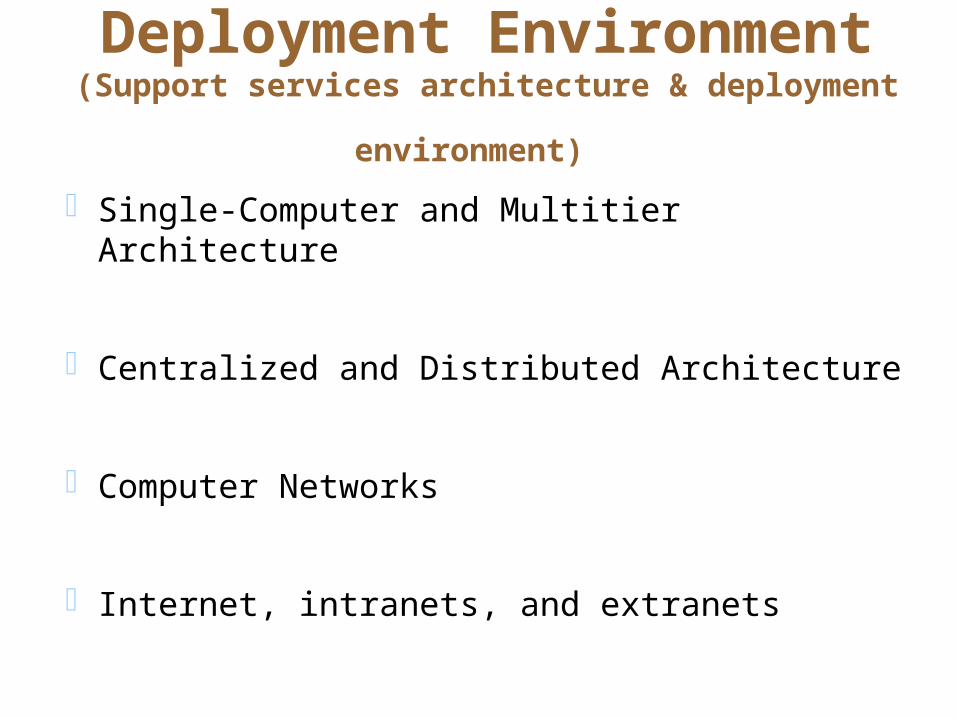
Deployment Environment(Support services architecture & deployment environment) Single-Computer and Multitier Architecture
Centralized and Distributed Architecture
Computer Networks
Internet, intranets, and extranets

Client/Server Architecture(Software architecture)
Client/server architecture tiers
Architectural issues for client/server software
Client and server communicate via well-defined
protocols over a physical network
Client/server architecture advantages
Client/server architecture disadvantages

Figure 7-9Client/Server Architecture with a Shared Database

Figure 7-11Interaction Among Multiple Clients and a Single Server

Three-Layer Client/Server Architecture
Variant of client/server architecture
Three-layers
The data layer
The business logic layer
The view (presentation) layer
Three-tier architecture advantages
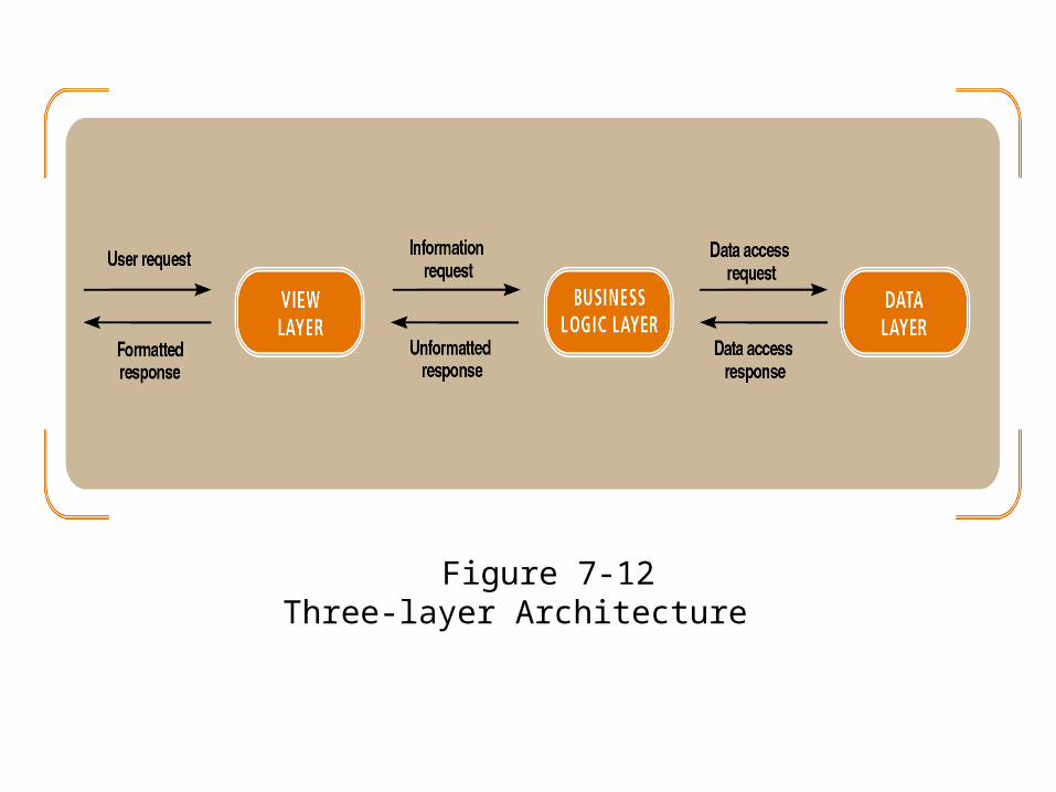
Figure 7-12Three-layer Architecture
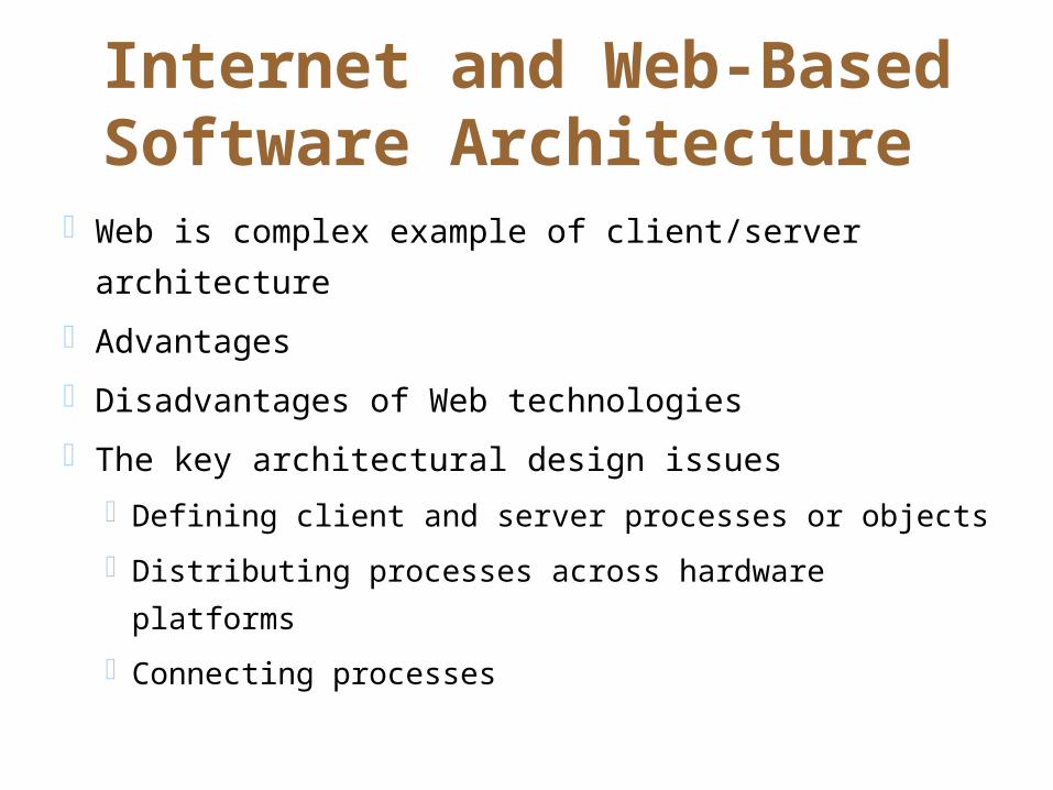
Internet and Web-Based Software Architecture
Web is complex example of client/server architecture
Advantages
Disadvantages of Web technologies
The key architectural design issues
Defining client and server processes or objects
Distributing processes across hardware platforms
Connecting processes

What is Object-Oriented Design?
The bridge between a user’s requirements and programming for the new system
An adaptive approach to development Requirements and design are done incrementally
within an iteration A complete set of designs may not be developed at
one time

Overview of Object-Oriented Programs
Object-oriented programs consist of a set of computing objects that cooperate to accomplish a result
Most object-oriented programs are event-driven
Instantiation of a class creates an object based on
the template provided by the class definition

Figure 8-1Object-oriented event-driven program flow
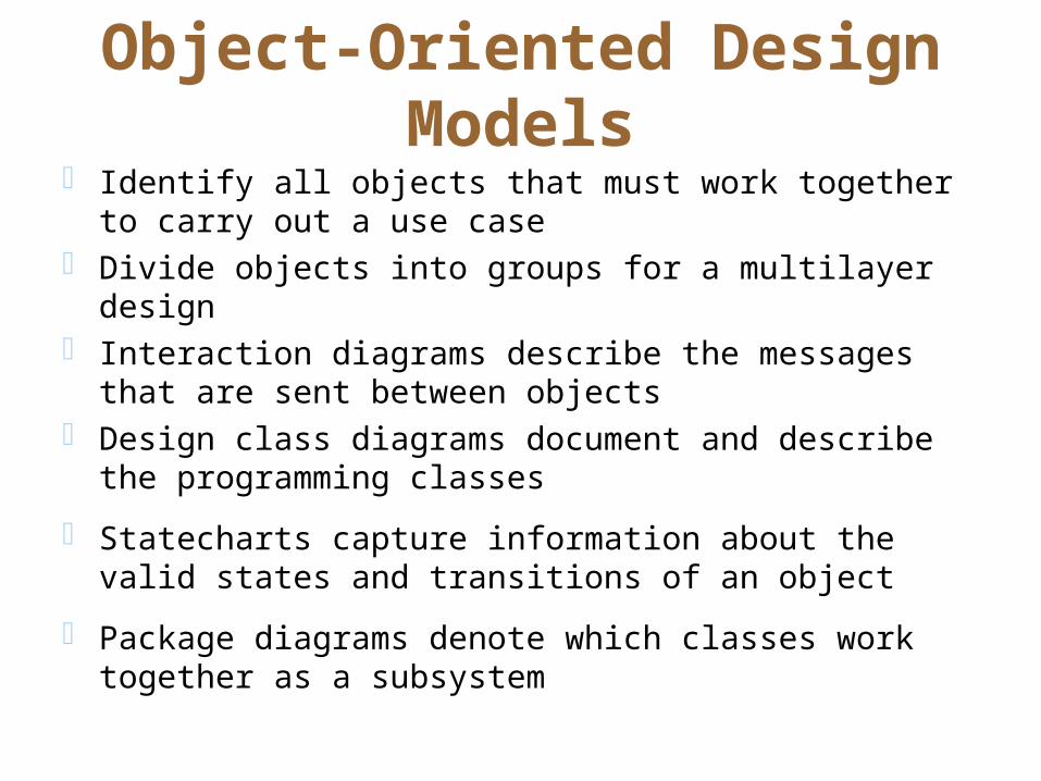
Object-Oriented Design Models Identify all objects that must work together to carry out a use
case Divide objects into groups for a multilayer design Interaction diagrams describe the messages that are sent
between objects Design class diagrams document and describe the
programming classes
Statecharts capture information about the valid states and transitions of an object
Package diagrams denote which classes work together as a subsystem

Figure 8-4 Design models with their respective input models

Design Classes and Design Class Diagrams
Design class diagrams are extensions of domain class model diagrams Elaborate on attribute details Define parameters and return values of methods Determine stereotypes
A first-cut design class diagram is based on the domain model and engineering design principles
Interaction diagrams are used to refine a design class diagram as development progresses

Figure 8-7Student class examples for the domain diagram and the design class diagram
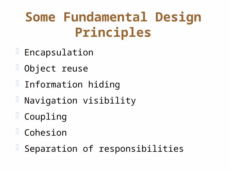
Some Fundamental Design Principles
Encapsulation
Object reuse
Information hiding
Navigation visibility
Coupling
Cohesion
Separation of responsibilities
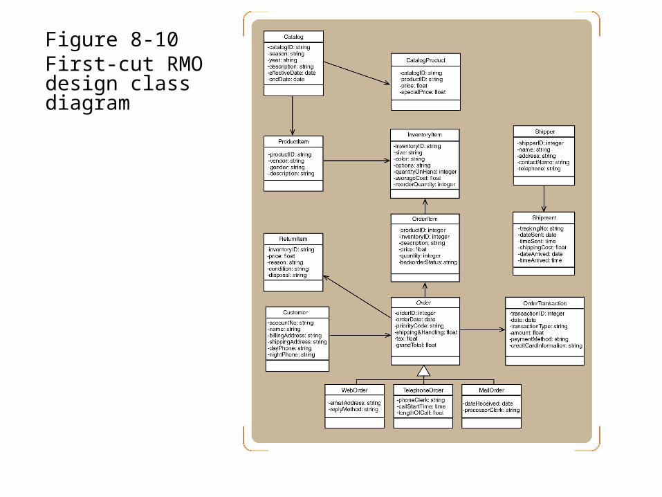
Figure 8-10First-cut RMO design class diagram

Interaction Diagrams–Realizing Use Cases and Defining Methods
Interaction diagrams are at the heart of object-oriented design
Realization of a use case Determine what objects collaborate by sending
messages to each other Object Responsibility
Knowing Doing

Use Case Controller
An artifact invented by the designer to handle a system function Serves as a collection point for incoming messages Intermediary between the outside world and the
internal system A single use case controller results in low
cohesion Several use case controllers raise coupling but
result in high cohesion
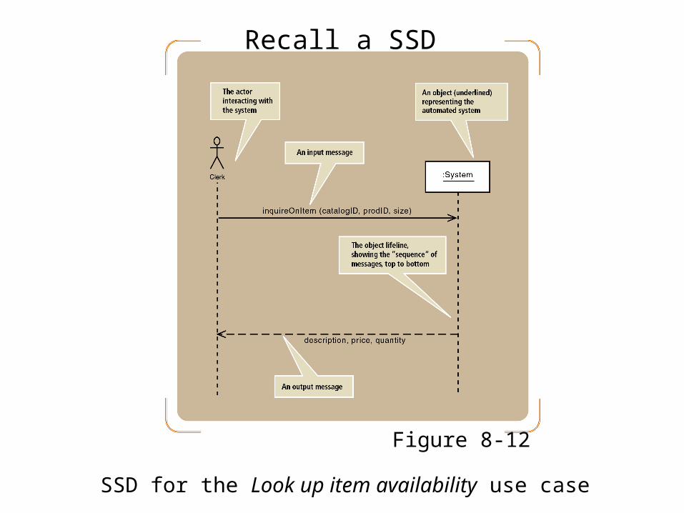
Figure 8-12SSD for the Look up item availability use case
Recall a SSD

First-Cut Sequence Diagram
Determine which other objects may need to be involved to carry out the use case
Replace the :System object with a use case controller object
Determine all of the internal messages that result from each input message
Identify the complete set of classes that will be affected by each message
Flesh out the components for each message Iteration, true/false conditions, return values, and passed
parameters

Figure 8-14 First-cut sequence diagram for the Look up item availability use case

Developing a Multilayer Design View layer
Design the user interface for each use case
Develop dialog designs for forms
Add the window classes to the sequence diagram
Data access layer
Initialize domain objects with data from the database
Query the database and send a reference object
Return information in the reference object

Figure 8-17Completed three-layer design for Look up item availability
Updating the Design Class Diagram
Add classes for the view and data access layers Update classes with method signatures
Constructor and get and set methods are optional Use case specific methods are required
Every message in a sequence diagram requires a method in the destination object
Include the new user controller classes and add navigation arrows

Figure 8-30Updated design class diagram for the domain layer
Package Diagrams-Structuring the Major Components
Associates classes of related groups One option is to separate the view, domain, and
data access layers into separate packages Indicate dependency relationships
Shows which elements affect other elements in a system
May exist between packages, or between classes within packages
Packages can be nested

Figure 8-31Partial design for a three-layer package diagram for RMO

Implementation Issues for Three-Layer Design
IDE tools can help programmers construct systems IDE tools can also make a system difficult to
maintain Creates window classes that generate class definitions Inserts business logic code into the user interface
Use good design principles when developing a system Define object responsibility for each layer
Summary
Design is driven by use cases
Two primary models developed during design Design class diagrams
Sequence class diagrams
Multilayer designs partition classes into groups View, domain, and data access layers
Communication diagrams are a viable alternative to sequence diagrams

Summary (continued)
Object-oriented design principles Encapsulation
Coupling
Cohesion
Navigation
Object responsibility
Package diagrams can group classes by subsystem or layer