Embed Size (px)
Citation preview

The Negative Branch Impedance in the Transformer Sequence Circuit Model
Elmo PriceABB Inc.
Krzysztof KulasekABB Inc.
Gary KobetTennessee Valley Authority

Introduction
• Common assumption: IN and IY0 do not change directions for faults on either side of the transformer, therefore a good polarizing quantity
• Current reversals occur due to a very small or negative low voltage (X) side branch impedance
Y1
H1
X1
X3
H2
H3 Y3
Y2
X2
XX
IN
IY0
C S
ZH0 (+/-) ZX0
ZY0
(a) Autotransformer with delta tertiary (b) Zero sequence circuit
IC0
H0 X0
N
N
IY0
*
*
* Polarizing Current

Introduction
• Aspects of transformer design that affect the positive and zero sequence T branch impedance model
• The development and effect of the T branch model on polarizing current reversal.
• A survey autotransformer applications from two utilities
• Discuss mitigation• Make recommendations

Leakage Impedance
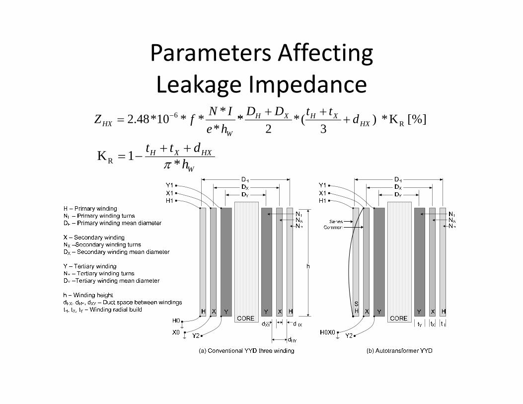
Parameters Affecting Leakage Impedance
]%[ K* )3
(*2
**
***10*48.2 R6
HXXHXH
WHX dttDD
heINfZ
W
HXXH
hdtt
*1KR

Winding Placement affectson Leakage Impedance

Impedance Testing
Single Phase Testing

T Branch Model
2
2
2

Three‐phase Autotransformer Positive Sequence Impedance Testing
ZHX1 ZHY1

Three‐phase Autotransformer Zero Sequence Impedance Testing
ZHX0 ZHY0

Effect of Core Type on Zero Sequence Impedance

Effect of Core Type on Zero Sequence Impedance

Phantom Tertiary

Effect of Core Type on Zero Sequence Impedance

T Branch Model
• ZY0 may vary 0.5 to 1.0 times positive sequence measurement
• Refer to IEEE Standard C57.12.90 – 2010 for zero sequence impedance testing

Impedances for Different Winding Arrangements
Winding Configuration Positive Sequence Impedance
Positive Sequence Impedance
H ‐ X H ‐ Y X ‐ Y H X Y1 Core‐TV‐LV‐HV 10.6 29.0 14.4 12.6 ‐2.00 16.42 Core‐LV‐TV‐HV 10.2 8.4 11.4 3.6 6.6 4.83 Core‐LV‐HV‐TV 10.4 39.7 70.3 ‐10.1 20.5 49.8
All impedances are in % on 0.6*280 MVA base at rated winding voltage. ZBase = kV2/MVA, ZW = ZBase x Z%/100, HVR ‐ regulating winding
280 MVA Autotransformer

Zero Sequence Currents for Single ‐G Ground Fault on HV and LV
SC Case Winding Configuration
HV (kA) LV (kA) TV (kA)Line Series
windingLine Common
windingLine Winding
1 faulton HV
1 ‐1.558 ‐1.558 3.734 ‐2.176 0.00 ‐0.242 ‐2.804 ‐2.804 2.42 0.384 0.00 11.933 ‐3.51 ‐3.51 5.69 ‐2.183 0.00 7.271
1 faulton LV
1 1.82 1.82 ‐7.69 5.87 0.00 9.8442 1.132 1.132 ‐4.957 3.826 0.00 6.6253 2.64 2.64 ‐5.01 2.365 0.00 ‐3.53
280 MVA Autotransformer

Determining k0
Zero Sequence T Branch Model
Perunit Current

Relative Amps in Three Winding YYD Transformers
Autotransformer Conventional

Application Criteria for Polarization
High Side Fault Low Side Fault
Delta 1 1
Neutral / /

Field Application StudyUtility A Utility B Both
Total units in survey 57 28 85
# (%) with negative high side branch impedance 0 0 0
# (%) with negative low side branchimpedance
42 (72%)
17 (61%)
60 (71%)
# (%) not suitable for tertiary current polarization, k0 > 1
1 (2%) 0 1 (1%)
# (%) not suitable for neutral current polarization, k0 > VX/VH
38 (67%)
10 (36%)
48(56%)
Summary of autotransformer application data

Field Application Study• Autotransformers are designed, unless otherwise specified,
with their winding configuration build from core such that negative low voltage branch impedance is rather common occurring in 71% of the cases studied.
• The negative impedances are generally small enough such that the low voltage source impedance overcomes the effect of the transformer’s negative low voltage branch impedance making the use of the delta tertiary suitable for 99% of the cases studied.
• The transformer’s neutral current is not suitable as a polarizing source in 56% of the cases .
• These numbers will vary with transformer design and likewise from utility to utility that use them

Field Application Study
Utility A• Most applications involving
newer technology used voltage polarizing
• Tertiary current polarizing was used mostly for legacy products where available
• Neutral current polarizing was not used
Utility B• Most applications involving
newer technology used voltage polarizing
• Tertiary current polarizing was used where dual polarization (using both voltage and current) was desired.
• Polarizing current derived from high and low voltage line ct connections was used in one application.
• Neutral current polarizing was used in some cases where tertiary current was not available and there were no application issues.

MitigationAlternative to Neutral Current Polarization
• Use delta tertiary polarization current if cts are available.
Buried or Non‐loaded Tertiary Loaded Tertiary

MitigationAlternative to Neutral Current Polarization
• Use equivalent delta tertiary polarization current if delta cts are not available.
Neutral and Low Side Cts High and Low Side Cts

Mitigation – Transformer Design
• Delta tertiary current reversal is eliminated by a varied number of designs changing the relative impedance between windings.– Example: placing the tertiary
between the series and common windings.
– Effects on transformer’s first and operating costs are considered.
• Specified by some utilities• Neutral current may still reverse
as it is dependent on VX/VH ratio for high side fault

Mitigation[Compensated] Polarizing Voltage
• Zero and Negative sequence voltages are far more reliable polarization methods if sensitivity is not an issue.
• This is particularly true in applications where mutual coupling affects the reliability of both zero sequence voltage and current polarization methods and negative sequence voltage polarization needs to be used.
• Microprocessor technology methods have been developed that reliably compensate zero and negative sequence polarizing voltages with the respective line zero or negative sequence current to address sensitivity issues

Mitigation[Compensated] Polarizing Voltage
• Zero sequence voltage compensated with zero sequence current

Conclusions• Voltage polarization and impedance compensated voltage
polarization are recommended as first choices.• Reliable polarization current can generally be obtained from the
delta tertiary winding. – There are a few exceptions where zero sequence source
impedance is very small and does not allow its use. – Schemes involving the neutral and line cts are available to provide
a proportional quantity when tertiary windings are not provided with cts.
– Each application should be reviewed with system changes.• Polarization current from the neutral ct is not generally reliable
and, therefore, not recommended where alternatives are available. – Using the neutral ct connected to line cts with an auxiliary
transformer may very well be suitable (above).

Conclusions• Accurate zero sequence testing is desired for development of the T branch model.
• Different winding configurations can eliminate the negative impedance. – The possible extra costs, first and evaluated, should be considered
• Different winding configurations can move the negative impedance to the high voltage side. – Possible for transformers with high VH/VX turns ratios (e.g. 345/34.5 kV).