Embed Size (px)
Citation preview

The Provision of an Initial Study of Multiple In Multiple Out Technology
Section 2: Literature Search
Professor Sana Salous
Contract: AY 4252 (510010100)
Anywhere WLAN!中国无线门户! http://www.anywlan.com
2006 年6月OFDM-MIMO专题
http://www.anywlan.com
2
List of Symbols C Channel capacity H Channel matrix I identity matrix N, n, nt Number of receive antennas M, m, nr Number of transmit antennas R correlation matrix r correlation coefficient λ wavelength λi Eigenvalue σi Singular value ρ Signal to noise ratio εi Optimum value for waterfilling
Anywhere WLAN!中国无线门户! http://www.anywlan.com
2006 年6月OFDM-MIMO专题
http://www.anywlan.com

3
GLOSSARY OF TERMS AOA Angle Of Arrival ASIC Application Specific Integrated Circuit AWGN Additive White Gaussian Noise BER Bit Error Rate BLAST Bell Laboratories Layered Space Time BLER Block Error Rate BS Base Station CDF Cumulative Distribution Function CDMA Code Division Multiple Access CIR Channel Impulse Response CLR Correlated Low Rank CSI Channel State Information CUBA Circular Uniform Beam Array D-BLAST Diagonal BLAST DOA Direction of Arrival DOD Direction of Departure DOF Degrees of Freedom DSP Digital Signal Processing ED Effective Dimensionality EDGE Enhanced Data rate for Global Evolution EDOF Effective Degrees Of Freedom ESPRIT Estimation of Signal Parameters via Rotational Invariance
Techniques FDD Frequency Division Duplex FDMA Frequency Division Multiple Access FDTD Finite Difference Time Domain G-MLD Group Maximum Likelihood Detection GSM Groupe Speciale Mobile or Global System for Mobile
Communication HDTV High Definition Television HF High Frequency HPBW Half Power Beam Width H-S Hybrid Selection iid independent identically distributed LOS Line of Sight MEA Multi-Element Array MCS Multi-Carrier System MI Mutual Information MIMO Multiple Input Multiple Output MISO Multiple Input Single Output MLED Maximum Likelihood Equalisation and Detection MMSE Minimum Mean Square Error MPC Multiple Path Components MRC Maximum ratio combining MS Mobile Station NLOS Non Line Of Sight OFDM Orthogonal Frequency Division Multiplexing OLOS Obstructed Line of Sight OSIC Ordered Successive Interference Cancellation OSTBC Orthogonal Space Time Block Codes
4
pdf probability density function PER Packet Error Rate PRBS Pseudo Random Binary Sequence QAM Quadrature Amplitude Modulation RF Radio Frequency rms root mean square Rx Receiver SIMO Single Input Multiple Output SINR Signal to Interference and Noise Ratio SNR Signal to Noise Ratio SISO Single Input Single Output STBC Space-Time Block Coding TDMA Time Division Multiple Access Tx Transmitter UHR Uncorrelated High Rank ULA Uniform Linear Array ULR Uncorrelated Low Rank UMTS Universal Mobile Telecommunication System V-BLAST Vertical BLAST WLAN Wireless Local Area Network WPMC Wireless Personal Multimedia Communication XPD Cross Polarisation Discrimination ZF Zero Forcing ZF_MRC Zero Forcing Maximal Ratio Combining 3G Third Generation 4G Fourth Generation
5
Contents Paper 1 Page 16 Layered Space-Time Architecture for Wireless Communication in a Fading Environment When Using Multi-Element Antennas G. J. Foschini, Bell Labs. Tech. Journal, Vol. 1, No.2, Autumn 1996, pp 41-59. Paper 2 Page 17 On Limits of Wireless Communications in a Fading Environment when Using Multiple Antennas G.J. Foschini and M.J. Gans, Wireless Personal Communications, Vol. 6, No. 3, March 1998, pp 311-335 Presentation 1 Page 19 Promises of Wireless MIMO Systems Mattias Wennstrom, Uppsala University, Sweden, http://www.signal.uu.se/courses/semviewgraphs/mw_011107.ppt Paper 3 Page 21 V-BLAST: An architecture for Realising very high data rates over the rich-scattering wireless channel P. W. Wolniansky, G. J. Foschini, G. D. Golden, R. A. Valenzuel, Proc. ISSSE’98, Pisa, Italy, Sept. 29, 1998. Paper 4 Page 23 Fading correlation and its effect on the capacity of multi-element antenna systems Da-Shan Shiu, Gerard J. Foschini, Michael J. Gans, and Joseph M. Kahn, IEEE Transaction on Communications, vol. 48, No. 3 March 2000, pp 502-513. Paper 5 Page 23 Estimating MIMO system performance using the correlation matrix approach Sergey Loyka and George Tsoulos, IEEE Communications Letters, vol. 6, No. 1, January 2002, pp 19-21. Paper 6 Page 24 New compound upper bound on MIMO channel capacity Sergey Loyka and Ammar Kouki, IEEE Communications Letters, vol.6, No. 3, March 2002, pp 96-98 Paper 7 Page 25 Channel capacity of MIMO architecture using the exponential correlation matrix Sergey Loyka, IEEE Communication Letters, vol. 5, No 9, September 2001, pp 369-371. Paper 8 Page 27 The impact of correlation on multi-antenna systems performance: correlation matrix approach. S. Loyka nd A. Kouki, IEEE 54th VTC conference, October 2001, pp 533-537 Paper 9 Page 27 Channel capacity of two-antenna BLAST architecture S. Loyka, Electronics Letters 19th August 1999, vol. 35, No. 17, pp 1421-1422

6
Paper 10 Page 27 Channel capacity of n-antenna BLAST architectureS. Loyka and J. Mosig, Electronics Letters, Vol. 36 No. 7, 30th March 2000, pp 660-661. Paper 11 Page 28 Spatial channel properties and spectral efficiency of BLAST architecture S. Loyka, and J.R. Mosig, AP2000, Davos, 9-14 April, 2000. Paper 12 Page 29 On MIMO channel capacity, correlations and keyholes: analysis of degenerate channels. S. Loyka, A. Kouki, IEEE Transaction on Communications, accepted 2002. Paper 13 Page 30 On the use of Jensen inequality for MIMO channel capacity estimation S. Loyka, and A. Kouki, Canadian Conference on Electrical and Computing Engineering, CCECE 2001, May 13-16, Toronto, Canada. Paper 14 Page 30 Correlation and MIMO communication architecture (Invited) Sergey Loyka, and Ammar Kouki, 8th International Symposium on Microwave and Optical Technology, Montreal, Canada, June 19-23, 2001. Paper 15 Page 31 MIMO channel capacity: Electromagnetic wave perspective S. Loyka, URSI 27th General Assembly, Maastricht, 2001August 17-24, 2002, paper 677. Paper 16 Page 32 V-BLAST outage probability: analytical analysis S. Loyka, http://www.site.uottawa.ca/~sloyka/papers/Final_paper_VTC02.pdf also paper presented at VTC 2002. Presentation 2 Page 32 New paradigm of wireless communications- MIMO architecture Sergey Loyka, 19 Dec. 2001, pp 1-48. http://www.site.uottawa.ca/~sloyka/ Paper 17 Page 33 On the capacity of the MIMO channel - A tutorial introduction (VTC 01) Bengt Holter http://www.ilab).ux.his.no/norsig/finalpapers/57.capacity_of_1992001154555.pdf Technical report 1 Page 36 Multiple input-multiple output (MIMO) communication systems Christian Schneider, Telenor R&D N 5/2001, ISSN 0809-102, Project no TXTV04, pp 45, 2001. Lecture notes 1 Page 36 Parallel Additive Gaussian Channels and Lecture notes: EE 7950: Statistical Communication Theory Christian Schlegel, http://www2.elen.utah.edu/~ee7950-5/
7
Lecture notes 2 Page 37 EE359 Wireless Communication fall 2001, Capacity of MIMO Channels - A Survey Anindya Poddar ([email protected]) http://www.stanford.edu/class/ee359/2001/proj2001.html Paper 18 Page 38 Effect of antenna separation on the capacity of BLAST in correlated channels Dimitry Chishik, Farrokh Rashid-Farroki, Jonathan Ling, and Angel Lozano, IEEE Communications Letters, Vol. 4, No. 11, November 2000, pp 337-339. Paper 19 Page 39 Keyholes, correlations and capacities of multi-element transmit and receive antennas Dmitry Chizhik, Gerard Foschini, Michael Gans, and Reinaldo Valenzuela, IEEE Transactions on Wireless Communications, vol. 1, No. 2, April 2002, pp 361-367. Paper 20 Page 40 Experimental verification of MTMR system capacity in controlled propagation environment Hao Xu, M.J. Gans, N. Amitay and R. A. Valenzuela, Electronics Letters 19th of July 2001, vol. 37, No. 15, pp 936-937. Paper 21 Page 40 MIMO channel capacity for fixed wireless: measurements and models H. Xu, M. Gans, N. Amitay, R.A. Valenzuela, T. Sizer, R. Storz, D. Taylor, M. McDonald and C.Tran, VTC 54th Atlantic city, October 2001, pp 1068-1072. Paper 22 Page 41 Outdoor BLAST measurement system at 2.44 GHz: calibration and initial results M. Gans, N. Amitay, Y. S. Yeh, H. Xu, T.C. Damen, R.A. Valenzuela, T. Sizer, R. Storz, D. Taylor, W.M. MacDonald, C. Tran and A. Adamiecki, IEEE Journal on Selected Areas in Communications, Vol. 20, No. 3, April 2002, pp 570-583. Presentation 3 Page 41 Mutliple antenna systems: a new wireless communication technology of extra-ordinary bandwidth efficiency for 3G and beyond. R. Valenzuela, www.bell-labs.com/user/rav/Internet2.pdf Paper 23 Page 43 Multiple input multiple output measurements and modeling in Manhattan D. Chizhik, J. Ling, P. Wolniansky, R. Valenzuela, N. Costa and K. Huber, IEEE Journal on Selected Areas in Communications, April 2003, Volume 21, Number 3 MIMO SYSTEMS AND APPLICATIONS: PART I Also presented at the VTS 56th Vehicular Technology Conference, VTC 2002, Vancouver Paper 24 Page 44 On the capacity formula for multiple input-multiple output wireless channels: a geometric interpretation P.F. Driessen and G.J. Foschini, IEEE Transactions on Communications, vol. 47, No. 2, February 1999, pp 173-176.
8
Paper 25 Page 45 Capacity of multiple antenna system in free space and above perfect ground P. Kyritsi and D. Chizhik, IEEE Communications Letters, Vol. 6, No. 8, August 2002, pp 325-327. Paper 26 Page 45 Information capacity of a random signature multiple input multiple output channel, P.B. Rapajic and D. Popescu, IEEE Transactions on Communications, Vol. 48, No. 8, August 2000, pp 1245-1248. Paper 27 Page 46 Spatial and temporal variation of MIMO channels and impacts on capacity Xu, Gans, Chizhik, Ling, Wolniansky, and Valenzuela, IEEE Proceeding International Conference on Communications, New York, pp 262-266, May 2001, ISSN 0-7803-7400-2/02 Paper 28 Page 47 Capacity of MIMO Systems Based on Measured Wireless Channels A. F. Molisch, M. Steinbauer, M. Toeltsch, E. Bonek, and R. S. Thomä, IEEE Journal on Selected Areas in Communications, Vol. 20, No. 3, April 2002, pp 561-569. Paper 29 Page 48 MIMO wireless channels: capacity and performance prediction D. Gesbert, H. Bolcskei, D. Gore, and A. Paulraj, IEEE Globecom 2000, San Fransisco, CA, vol. 2, Nov. 2000, pp 1083-1088, http://heim.ifi.uio.no/~gesbert/papers/globecom00.pdf Paper 30 Page 49 Dynamic capacity estimation for the indoor wireless channel with MIMO arrays and pedestrian traffic K. Ziri-Castro, W. G. Scanlon and F. Tofoni, http://telecoms.eeng.dcu.ie/symposium/papers/C2.pdf Paper 31 Page 50 Performance limits in fading MIMO channels A. Paulraj, D. Gore, and R. Nabar, WPMC 02, October 27-30, 2002, Hawaii, pp 7-11 Paper 32 Page 50 Double-directional radio channel estimation at 2 GHz for high-speed vehicular mobiles-experimental results H. Hofstetter, M. Steinbauer, C.F. Mecklenbrauker [email protected], http://www.ftw.at Paper 33 Page 51 Double directional superresolution radio channel measurements H. Hofstetter, C.F. Mecklenbrauker, and M. Steinbauer, http://www.nt.tuwien.ac.at/mobile/papers/mobile_radio_channel/Allerton_Bo/paper.pdf Paper 34 Page 51 Double directional channel measurements E. Bonek and M. Steinbauer, 11th International Conference on Antennas and Propagation, 17-20 April 2001, pp. 226-230
9
Paper 35 Page 51 MIMO vector channel sounder measurement for smart antenna system evaluation R. S. Thoma, D. Hampicke, A. Richter, G. Sommerkorn and U. Trautwein European Transactions on Telecommunications, ETT, Vol. 12, No.5, Special Issue on Smart Antennas, September/October 2001, pp 427- 438, www-emt.tu-ilmenau.de/WWWdocuments/ downloads/paper/2001-002.pdf Presentation 4 Page 52 MIMO measurement and joint M-D parameter estimation of mobile radio channels R. Thoma, A. Richter, D. Hampicke, G. Sommerkorn, University of Ilmenau Paper 36 Page 53 Outdoor MIMO wireless channels: models and performance prediction D. Gesbert, H. Bolcskei, D. Gore, and A. Paulraj http://heim.ifi.uio.no/~gesbert/papers/mimo_final.pdf IEEE Trans Communications 2002 Paper 37 Page 53 Capacity obtained from multiple input multiple output channel measurements in fixed wireless environments at 2.5 GHz V. Ecreg, P. Soma, D.S. Baum, A.J. Paulraj, www.nari.ee.ethz.ch/commth/pubs/ viewpub.php?ident=ESBP02 Paper 38 Page 55 Multiple-input multiple output (MIMO) wireless systems H. Bolcskei and A.J. Paulraj, The Communications Handbook, 2nd Edition, J. Gibson, Ed. pp 1-22 Paper 39 Page 56 MIMO a solution for advanced wireless access M.A. Beach, D.P. McNamara, P.N. Fletcher and P. Karlsson, ICAP 2001, Manchester, pp 231-235 Paper 40 Page 56 Systemes de communications multi-antennes influence du canal de propagation P. Guguen, P. Lopez, and G. El Zein, 4em Journees d’etudes Propagation Electromagnetique dans l’atmosphere du decanetrique a l’angstrom, Rennes, 13-15, March 2001, session 6. Paper 41 Page 57 Detection algorithm and initial laboratory results using V-BLAST space-time communication architecture G.D. Golden, C.J. Foschini, R.A. Valenzuela and P.W. Wolniansky, Electronics letters, 7 January 1999, volume 35, number 1 Chapter 9 Page 57 MIMO channels, pp 233-265, Space time wireless channels, G. Durgin, Prentice Hall Paper 42 Page 57 Multiple input multiple ouput (MIMO) radio channel measurements C.C. Martin, J.H. Winters, N.R. Sollenberger, VTC2000, ISSN 0-7803-6507, pp 774-779.
10
Article from Pentek publications Page 58 The Pentek Pipeline, Summer 2001, vol. 10, No. 2 Smart antenna experiments for 3G and 4 G cellular systems. Paper 43 Page 58 Multiple input multiple ouput (MIMO) radio channel measurements and experimental implementation for EDGE C.C. Martin, J.H. Winters, H.H. Zeng, N.R. Sollenberger and A. Dixit, IEEE publication, ISSN 0-7803-6514-3, pp 738-742 Paper 44 Page 59 MIMO radio channel measurements: performance comparison of antenna configurations C.C. Martin, J.H. Winters, N.R. Sollenberger, IEEE pub. 2001, ISSN 0-7803-7005-8, pp 1225-1229 Paper 45 Page 60 MIMO channel capacity based on measurement results M. Steinbauer, A. Molisch, A. Burr and R. Thoma, Proc. of the European Conference on Wireless Technology (ECWT), Oct. 2000, Paris, France, pp 52-55. Paper 46 Page 61 Experimental investigation of the joint spatial and polarisation diversity for MIMO radio channel J. P. Kermoal, L. Schumacher, F. Frederiksen, WPMC´01, Aalborg, Denmark, September, 2001, cpk.auc.dk/~schum/MIMO/Publications/p1258.pdf - Paper 47 Page 61 Capacity of MIMO systems with antenna selection A. Molisch, M.Z. Win, and Jack Winters, IEEE 2001, pp 570-574, ISSN 0-7803-7097. Paper 48 Page 62 On optimum MIMO with antenna selection R. Blum and J. Winters, IEEE Communications Letters, vol. 6, No. 8, August 2002, pp 322-324 Paper 49 Page 63 On the capacity of cellular systems with MIMO R. Blum, J. Winters, and N.R. Sollenberger, IEEE Communications Letters, vol. 6, No. 6, June 2002, pp 242-244. Paper 50 Page 63 Spatial characterisation of indoor radio channel measurements at 5 GHz R. Stridh and B. Ottersten, 1st IEEE Sensor Array and Multichannel Signal Processing Wokshop, Paper 51 Page 64 MIMO channel capacity on a measured indoor radio channel at 5.8 GHz R. Stridh, P. Karlsson and B. Ottersten, Proc. of Asilomar Conference on Signals, Systems and Computers, 2000.
11
Paper 52 Page 64 High data rate indoor wireless communications using antenna array M. Gans, R. Valenzuela, J. Winters, and M. Carloni, IEEE, 1995, pp 1040-1046, ISSN 0-7803-3002 Paper 53 Page 64 Effect of fading correlation on adaptive arrays in digital mobile radio J. Salz and Jack Winters, IEEE Transaction on Vehicular Technology, vol. 43, No. 4, Nov. 1994, pp 1049-1057. Paper 54 Page 65 The impact of antenna diversity on the capacity of wireless communication systems J. Winters, J. Salz, and R. G. Gitlin, IEEE Transactions on Communications, vol. 42, No. 2/3/4 Feb./Mar/April, 1994, pp 1740-1751. Paper 55 Page 65 On capacity of MIMO systems in correlated channels M. Ivrlac, T. Kurpjuhn, C.Brunner, and J.Nossek , In ITG-Fokusprojekt Mobilkommunikation 'Systeme mit intelligenten Antennen', Ilmenau, Germany, 2001, http://www.nws.ei.tum.de/cgi-bin/nws/publications?LANG=de&WER=miiv Paper 56 Page 66 Influence of environment on capacity of LOS city street MIMO channel N. Tarhuni and T. O. Korhonen, http://www.hut.fi/Units/Radio/URSI02/ursi_tarhuni.pdf, Paper 57 Page 66 arrowband MIMO channel modelling for LOS indoor scenarios K.Yu DM. Bengtsson, B. Ottersten and M. Beach, URSI 27th General Assembly, Maastricht, 2001August 17-24, 2002, paper 0162 Paper 58 Page 67 An experimental broadband 4 by 4 MIMO test-bed B. Vandeweile and P.Mattheijssen, URSI 27th General Assembly, Maastricht, 2001August 17-24, 2002, paper 1134 Paper 59 Page 67 Broadband measurement analysis of indoor space-time channels G.Dolmans M.Colllados, URSI 27th General Assembly, Maastricht, 2001August 17-24, 2002, paper 1139 Paper 60 Page 67 Experimental investigation of multipath richness for multi-element transmit and receive antenna arrays J.P.Kermoal, P.E.Mogensen S.H.Jensen,J.B.Anderson, F.Frederiksen, T.B. Sorensen and K.I.Pedersen, IEEE conference on vehicular technology, VTC 2000 Spring, Tokyo, Japan, May 2000, pp 2004-2008 Paper 61 Page 68 Antenna arrays in mobile communications: gain, diversity, and channel capacity J. B. Andersen, IEEE Antennas and Propagation Magazine, vol. 42, No. 2, April 2000, pp 12-16
12
Paper 62 Page 69 Capacity of MIMO systems in realistic cellular wireless systems A.G. Burr, IEE conference publication 02/112, ‘Getting the most out of the radio spectrum’, 24-25 October 2002, 26/1-26/5 Paper 63 Page 69 Digital wireless communications using MIMO links: applications to broadband mobile systems Overview by Professor David Gesbert, http//www.ifi.uio.no/¬gesbert/mimo_research.html Paper 64 Page 70 Smart antennas and spatial multiplexing D. Gesbert, http://www.ifi.uio.no/~gesbert/spatialmux_primer.htn Paper 65 Page 70 An antenna solution for MIMO Channels: the switched parasitic antenna M. Wennstrrom and O. Svantesson, IEEE Symposium on Personal Indoor and Mobile Radio Communication (PIMRC) 2001, San Diego, USA, September 30- October 3 2001. http://www.signal.uu.se/Publications/pdf/c0114.pdf Presentation 5 Page 70 The MIMO channel capacity potential-how much as possible? Christian Schlegel, WPMC 2002, October 30, 2002, Hawaii, www.ee.ualberta.ca/hcdc Paper 66 Page 71 The diversity gain of transmit diversity in wireless systems with Rayleigh fading J. Winters, IEEE Transactions on Vehicular Technology, Vol. 47, No.1, Feb. 1998, pp 119-123 http://www.jackwinters.com/00661038.pdf Paper 67 Page 71 The range increase of adaptive versus phased arrays in mobile radio systems J. Winters and M. J. Gans, IEEE Transactions on vehicular technology vol. 48 No. 2 March 1999, pp 353-362. Paper 68 Page 72 On the capacity of radio communication systems with diversity in a Rayleigh fading environment J. Winters, IEEE journal on selected areas in communications vol. SAC-5 June 1987, pp 871-878 Paper 69 Page 72 Experimental characterization of the MIMO wireless channel: data acquisition and analysis J.Wallace, M. Jensen, A. Swindlehurst, and B. Jeffs, IEEE Transaction on Wireless Communications, March 2003, http://goliath.ee.byu.edu/grad1/users/swindle/www_docs/pdffiles/wallace.pdf Paper 70 Page 73 Fundamental limits of MIMO capacity for spatially constrained arrays T.S. Pollock, T.D.Abhayapala, and R.A. Kennnedy, Austrialian Communication Theory Workshop Proceedings 2003
13
Paper 71 Page 74 Predicting multi element receive and transmit array capacity outdoors with ray tracing J. Ling, D. Chizhik, R.Valenzuela, VTC 2001, http://www.bell-labs.com/org/wireless/wisepub/vtc2001_jonling.pdf Paper 72 Page 74 Simulating polarization diversity and power allocation in MIMO channels L. Schumacher, J.P. Kermoal, K.I. Pedersen, P.E. Mogensen, EPMCC, Vienna 20-22 February 2001 Paper 73 Page 75 Rapid prototyping design of a 4 by 4 BLAST over UMTS system M. Guillaud S. Das, A. Burg, M. Rupp, E. Beck, Proceedings of the 35th Asilomar Conference on Signals,Systems and Computers, Pacific Grove, CA, USA, November 4-7, 2001. http://www.eurecom.fr/~guillaud/publications/blast6.pdf Paper 74 Page 75 METRA: Experimental investigation of MIMO radio channels for indoor picocell scenarios J. P. Kermoal, L. S. Schuacher, P.E. Mogensen, and K. I. Pedesen, F. Frederiksen Proceedings of IST Mobile Summit 2000, October, 2000, pp. 509-514, Galway, Ireland http://www.ist-metra.org/papers/Summit2000_4_Kermoal.pdf Paper 75 Page 76 Experimental investigation of correlation properties of MIMO radio channels for indoor picocell scenarios J. P. Kermoal, L. S. Schuacher, P.E. Mogensen, and K. I. Pedesen, Proceedings of VTC 2000 Fall, September, 2000, Vol. 1, pp. 14-21, Boston, USA Paper 76 Page 76 A stochastic MIMO radio channel model with experimental validation J. P. Kermoal, L. Schuacher, K. I. Pedesen, P. E. Mogensen and F. Frederiksen, IEEE Journal on Selected Areas in Communications, Vol. 20, No. 6, August 2002, pp 1211-1226. Paper 77 Page 77 Channel characterization and modelling for the next generation MIMO wireless communication M. Jensen, J. W. Wallace and A. L. Swindlehurst, Fifth Wireless World Research Forum meeting Digest, http://www.Wireless-world-research.org, Tempe, AZ Mar 7-8 2002. (IST), Jensen-Byu-wwrf2002 Paper 78 Page 78 Models for MIMO propagation channels, a review K. Yu and B. Ottersten, Wiley Journal on Wireless Communications and Mobile Computing, Special issue on adaptive antennas of MIMO systems, 8-7-2000 Paper 79 Page 80 Fundamental capacity of MIMO channels A. Goldsmith, S.A. Jafar, N. Jindal and S. Vishwanath, Department of Electrical Engineering, Stanford University, wsl.Stanford-edu/~ee359/mimo_tutorial.pdf
14
Paper 80 Page 80 Improved Techniques for 4 Transmit and 4 Receive Antenna MIMO-OFDM for Wireless Communications R.S. Blum, Q.Yan, Y.Li and J.H.Winters, IEEE Transactions on Communications vol. 49 No. 11 Nov. 2001 pp 1873-1878 Paper 81 Page 80 Signal Detection for MIMO-OFDM Wireless Communications Ye Li, J.H. Winters, and N. R. Sollenberger, IEEE Int. Conf. Common. June 2001 pp 3077-3081 Paper 82 Page 80 Improved Space-Time Coding for MIMO-OFDM Wireless Communications R.S. Blum, Y.Li, J.H.Winters and Q.Yan, VTC01, ISSN 0-7803-6728-6/$10.00, 2001IEEE, pp 1298-1302 Paper 83 Page 80 Mutual coupling effects on the capacity of multielement antenna systems T. Svantesson, A. Ranheim, IEEE ICASSP 01, Salt Lake City, Utah, may 2001 Paper 84 Page 81 Attainable throughput of an interference-limited multiple-input multiple-output (MIMO) cellular system S. Carteux, P.F. Driessen, and L.J. Greenstein, IEEE Transaction on Communications, Vol. 49, No. 8, August 2001, pp 1307-1311 Paper 85 Page 82 BLAST training: estimating channel characteristics for high capacity space-time wireless T. L. Marzetta, Proc. of 37th Annual Allerton Conference on Communication, Control, and Computing, Monticello, IL, Sept. 22-24, 1999 Paper 86 Page 82 How much training is needed in multiple-antenna wireless links? B. Hassibi and B. Hochawld, IEEE Transactions on Information Theory, vol.49, no.4, Apr. 2003, pages 951-964. Paper 87 Page 82 MIMO-capacities for COST 259 scenarios M. Stege, M. Bronzel, and F. Fettweis, University of Technology Dresden www.ifn.et.tu-dresden.de/MNS/veroeffentlichungen/ 2002/Stege_M_IZS02.pdf Paper 88 Page 83 The MIMO cube – a compact MIMO antenna J. B. Andersen and B. N. Getu, 5th International Symposium on Wireless Personal Multimedia Communications, WPMC02, Hawaii, October 27-30, 2002, pp 112-114 Paper 89 Page 83 Detection techniques for V-BLAST in frequency selective fading channels D.K.C. So and R.S. Cheng, in Proceeding of IEEE Wireless Communications and Networking Conference 2002, vol. 1, pp. 487-491, 17-21 March 2002, Orlando Florida, USA
2006 年6月OFDM-MIMO专题 http://www.anywlan.com

15
Paper 90 Page 84 Performance evaluation of space-time coding over frequency selective fading channels D.K.C. So and R.S. Cheng, in Proceeding of IEEE Vehicular Technology Society Conference VTC Spring 2002, vol. 2, pp. 635-639, 6-10 May 2002, Birmingham Alabama, USA. Paper 91 Page 84 BER and spectral efficiency of a MIMO system B. N. Getu and J. B. Andersen, 5th International Symposium on Wireless Personal Multimedia Communications, WPMC02, Hawaii, October 27-30, 2002, pp 397-401 Paper 92 Page 84 MIMO wireless systems: principles, potential, problems and concepts A. Burr, COST 273 workshop, pp 1-8 Paper 93 Page 84 Channel capacity evaluation of multi-element antenna systems using spatial channel model A. Burr, AP2000 Davos, paper 231
2006 年6月OFDM-MIMO专题 http://www.anywlan.com
16
Paper 1 Layered Space-Time Architecture for Wireless Communication in a Fading Environment When Using Multi-Element Antennas G. J. Foschini, Bell Labs. Tech. Journal, Vol. 1, No.2, Autumn 1996, pp 41-59.
This is the first paper in which Bell Labs propose BLAST as communication architecture for the transmission of high data rates using multiple antennas at the transmitter and receiver. The application envisaged for these systems were point to point communication systems such as: 1. Indoor wireless LAN. 2. Fixed wireless access network 3. Wireless local loop 4. Building to building wireless communications The paper provides key expressions for the enhanced capacity. These expressions are derived under the following assumptions: 1. Transmitted signal has fixed narrow bandwidth such that the channel can be considered flat
fading i.e. the transfer function is a complex scalar. The transmitted signals on the different antennas are assumed to be statistically independent Gaussians.
2. Total transmitted power is independent of the number of transmit antennas i.e. when the antennas are increased to n, the total power is divided equally between the antennas so that power per antenna = Pt/n.
3. Noise at the receiver is AWGN. The noise at each of the antenna outputs is independent and of identical power N.
4. Received signal at each antenna is the sum of all the transmitted signals. The average power at the output of each receiving antenna is P. Average power is spatial average.
5. Average SNR at each receive antenna, ρ=P/N. 6. Matrix channel impulse response is g(t) and is equal to n by m. h(t) denotes the normalised
form of g(t) where each element of h(t) has a spatial average power loss of unity (i.e.
hn
gT
ρ= )
7. The data are transmitted in bursts, which are assumed to be long enough to apply information theory and short enough to assume that the channel coefficients do not change during a single burst of data i.e. quasi-stationary. For example for several Msymb/s with several thousand symbols in a burst the channel changes on a scale of seconds.
8. The channel is unknown to the transmitter but is tracked at the receiver: need to transmit a training sequence.
9. The channel is assumed to be Rayleigh distributed. For half a wavelength separation between elements, H is approximated by a matrix having independent identically distributed (iid), complex, zero-mean, unit-variance entries: • Hij =Normal(0,1/√2) +j Normal(0,1/√2) • The magnitude squared of each element is a chi-squared variate with two degrees of
freedom denoted by χ22 but normalised so the expected value is 1, i.e. E|Hij|2=1.
Under conditions 1-8 the channel capacity for an n by m system is given by: 1. Generalised capacity formula for n by m antenna

17
( )[ ]tcm HHnIC ./detlog2 ρ+= b/s/Hz
tc: complex transpose 2. For the case of 1 by n (optimum ratio combining) and condition 9
[ ]nC 22
2 1log ρχ+= b/s/Hz Capacity curves were given which showed a linear relationship with n. With n = 8 at 1 % outage and 21-dB average SNR at each receiving element, 42 b/s/Hz is achieved. The capacity is more than 40 times that of a (1,1) system at the same total radiated transmitter power and bandwidth. The paper proposes two architectures, V-BlAST and D-BLAST for transmission and also discusses the processing of the received signals. Definitions and abbreviations 1. Capacity: is the limit to error free bit rate that is provided by information theory, which can
only be approached with the advance of technology. Any working system can only achieve a bit rate (at a desirable BER) that is only a fraction of capacity.
2. Channel outage: occurs when the desired BER is no longer achievable. 3. AWGN: Additive white Gaussian noise. Paper 2 On Limits of Wireless Communications in a Fading Environment when Using Multiple Antennas G.J. Foschini and M.J. Gans, Wireless Personal Communications, Vol. 6, No. 3, March 1998, pp 311-335 This paper is similar to paper 1 but contains additional capacity equations and simulations. The assumptions are similar, hence additional comments with regard to these assumptions were added to the list of paper 1. The paper however, points out a number of difficulties in the actual implementation of a MIMO system: 1. Feedback of the channel parameters to the transmitter to direct its transmission to the 'good
channel'. This is due to: • The required significant processing to exploit Multiple Element Arrays. • The extra time involved in incorporating the feedback loop could erode the validity of
assuming that the channel is virtually unchanged. 2. Antenna design: to ensure that the coefficients of the channel matrix are un-correlated (iid),
the antennas should be separated by half a wavelength. This requires considerable space on the user unit or the ability to cram as many antennas as possible in a small space with perhaps spacing less than the ideal λ/2 and using possibly different polarization. This increases the coupling between antennas, which makes it difficult to match the antenna impedance for efficient energy transfer to a receiver or from a transmitter. Also the coupling causes a further increase in the correlation between antenna signals. The amount of mutual
18
coupling is a function of the spacing between antennas, the number of antennas, and the direction of each ray relative to the array plane.
The capacity equations provided in this paper cover a wider range than those in the first paper and cover various configurations which include in addition to the traditional single transmit single receive (SISO) configuration, transmit diversity (MISO) and receive diversity (SIMO) and MIMO. The equations for SISO, SIMO and MIMO configurations are given below: 1. SISO: The standard formula for the Shannon capacity expressed in b/s/Hz is
+= 2
2 1log HC ρ b/s/Hz
where the normalized channel power transfer characteristic is |H|2 which is simply a complex scalar. For high SNR a 3 dB increase in ρ gives another bit/cycle capacity. 2. SIMO channels: usual receive diversity. Equations for maximal ratio combining (MRC) and
for selection diversity are given below:
+= ∑
=
m
iiHC
0
22 1log ρ b/s/Hz for MRC
+= 2
2 max1log mm HC ρ b/s/Hz for selection diversity
In the above equation the receiver picks up the strongest component between all the antennas. The above shows that selection diversity is inferior to MRC. 3. MIMO equation is similar to that given in the first paper, that is
( )[ ]tcm HHnIC ./detlog2 ρ+= b/s/Hz
For the case when the channel matrix is equal to the identity matrix and n=m (the case of orthogonal parallel channels)
( )[ ] ( )∞→→+= nasnnC )2ln(//1log2 ρρ b/s/Hz
( )[ ]nnC /1log2 ρ+=
That is the capacity increases linearly with n rather than logarithmically as SNR increases. If all the power is transmitted on one of the lines i.e. n = 1, then the capacity is only equal to
[ ]ρ+= 1log2C . The capacity equations for non-spatial multiplexing with Rayleigh iid fading, are also given in terms of the chi-squared variate as follows: 1. SISO system
[ ]22
2 1log ρχ+=C b/s/Hz 3. SIMO system (MRC)
[ ]nC 22
2 1log ρχ+= b/s/Hz
2006 年6月OFDM-MIMO专题 http://www.anywlan.com

19
4. MISO (transmit diversity) n by 1
+= n
nC 2
22 1log χρ b/s/Hz
5. Combined transmit-receive diversity for n transmit and m receive
+> ∑
−−=k
m
mnk nC 2
22
)1(1log χρ b/s/Hz
6. Spatial cycling (n transmit and m receive) but the signal is spatially cycled using one transmitter at a time
[ ]min
inC 2
22
11log1 ρχ+= ∑
= b/s/Hz
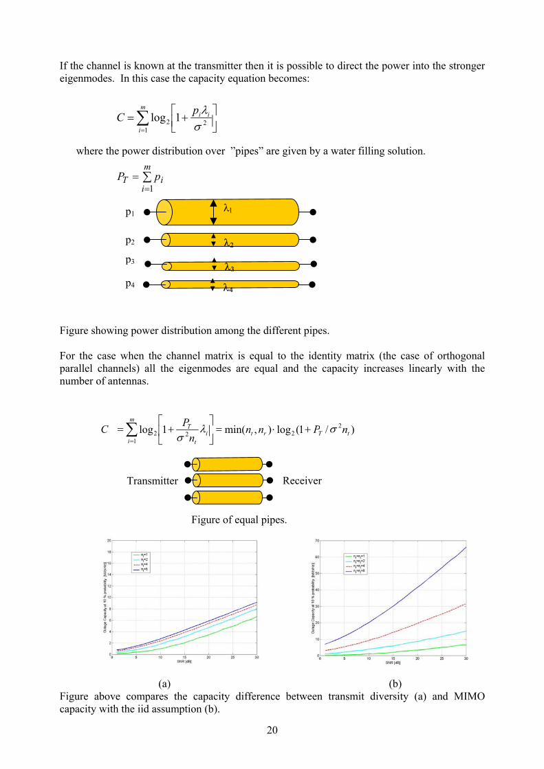
In 3-5 above the transmitter(s) sends the same set of data on all the antennas either simultaneously or sequentially with or without coding. Configurations 5 and 6 can be termed as MIMO. However, since same data are transmitted on all the antennas, configurations 5 and 6 are a form of diversity and not spatial multiplexing. Presentation 1 Promises of Wireless MIMO Systems Mattias Wennstrom, Uppsala University, Sweden http://www.signal.uu.se/courses/semviewgraphs/mw_011107.ppt The presentation covers the definitions of the channel capacity for transmit and receive diversity as in paper 2 in addition to spatial multiplexing which is given by:
where in the above equation m=min(nt, nr), ρσ
=2TP and H* is equal to Htc and λi is the ith
eigenmode of HH*. Figure showing m = min(nr, nt) parallel channels, with equal power allocated to each ”pipe”
∑ =
+ =
=
+ =
m
i i
t
T
t T
nP
HH n
P I C
1 2 2
* 2 2
1 log
det log
λ σ
σ
λ1
λ2
ReceiverTransmitter
2006 年6月OFDM-MIMO专题 http://www.anywlan.com
20
If the channel is known at the transmitter then it is possible to direct the power into the stronger eigenmodes. In this case the capacity equation becomes: Figure showing power distribution among the different pipes. For the case when the channel matrix is equal to the identity matrix (the case of orthogonal parallel channels) all the eigenmodes are equal and the capacity increases linearly with the number of antennas.
Figure of equal pipes. (a) (b) Figure above compares the capacity difference between transmit diversity (a) and MIMO capacity with the iid assumption (b).
∑=
+=
m
i
iipC1
22 1logσ
λ
where the power distribution over ”pipes” are given by a water filling solution.
∑=
=m
iiT pP
1
λ1
λ2
λ3
λ4
p1
p2
p3
p4
Transmitter Receiver
)/1(log),min(1log 22
1 2 2 tTrt
m
i i
t T nPnnn
P C σ λ σ
+ ⋅ =
+ = ∑
=
21
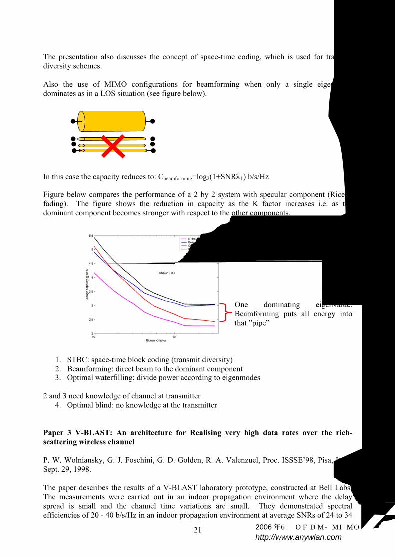
The presentation also discusses the concept of space-time coding, which is used for transmit diversity schemes. Also the use of MIMO configurations for beamforming when only a single eigenmode dominates as in a LOS situation (see figure below). In this case the capacity reduces to: Cbeamforming=log2(1+SNRλ1) b/s/Hz Figure below compares the performance of a 2 by 2 system with specular component (Ricean fading). The figure shows the reduction in capacity as the K factor increases i.e. as the dominant component becomes stronger with respect to the other components.
One dominating eigenvalue. Beamforming puts all energy into that ”pipe”
1. STBC: space-time block coding (transmit diversity) 2. Beamforming: direct beam to the dominant component 3. Optimal waterfilling: divide power according to eigenmodes
2 and 3 need knowledge of channel at transmitter
4. Optimal blind: no knowledge at the transmitter
Paper 3 V-BLAST: An architecture for Realising very high data rates over the rich-scattering wireless channel P. W. Wolniansky, G. J. Foschini, G. D. Golden, R. A. Valenzuel, Proc. ISSSE’98, Pisa, Italy, Sept. 29, 1998. The paper describes the results of a V-BLAST laboratory prototype, constructed at Bell Labs. The measurements were carried out in an indoor propagation environment where the delay spread is small and the channel time variations are small. They demonstrated spectral efficiencies of 20 - 40 b/s/Hz in an indoor propagation environment at average SNRs of 24 to 34
2006 年6月OFDM-MIMO专题 http://www.anywlan.com

22
dB. The system was implemented at 1.9 GHz with 24.3 ksymbols/sec in a bandwidth of 30 kHz. The system was operated in a laboratory with a separation of 12 m. The antenna arrays consisted of λ/2 wire dipoles mounted in various arrangements. The measurements showed that the results were independent of the small detail of the array geometry. The number of antenna elements was 8 at the transmitter and 12 at the receiver. The data were organised in blocks of 100 symbol duration where 20 symbols were used for training. In the experiment each of the substreams utilised uncoded 16-QAM i.e. 4 bits/symbol/transmitter so that the payload block size is 8 by 4 by 80=2560 bits giving a raw spectral efficiency of 25.9 b/s/Hz. The payload is 80% or 20.7 b/s/Hz (80 symbols of data to 20 symbols of training sequence) corresponding to payload data rate of 621 kbps in 30 kHz bandwidth. V-BLAST shown in figure below was implemented in preference to D-BLAST due to the implementation complexity of D-BLAST. The essential difference between the two systems lies in the vector encoding process. In D-BLAST, redundancy between the substreams is introduced through the use of specialized inter-substream block coding. The D-BLAST code blocks are organized along diagonals in space-time. It is this coding that leads to D-BLAST’s higher spectral efficiencies for a given number of transmitters and receivers. In V-BLAST, however, the vector encoding process is simply a demultiplex operation followed by independent bit-to-symbol mapping of each substream. No inter-substream coding, or coding of any kind, is required, though conventional coding of the individual substreams may be applied. The paper describes the processing required to extract the data. It is important to point out the following: V-BLAST, is essentially a single-user system, which uses multiple transmitters. It differs from the traditional multiple access schemes in: First, unlike code-division or other spread-spectrum multiple access techniques, the total channel bandwidth utilized in a BLAST system is only a small fraction in excess of the symbol rate, i.e. similar to the excess bandwidth required by a conventional QAM system. Second, unlike FDMA, each transmitted signal occupies the entire system bandwidth. Finally, unlike TDMA, the entire system bandwidth is used simultaneously by all of the transmitters all of the time. If one ”pipe” is bad in BLAST we get errors ...
Figure showing V-BLAST (after presentation 1)
Time
V-BLAST Antenna
s1 s1 s1 s1 s1 s1 s2 s2 s2 s2 s2 s2 s3 s3 s3 s3 s3 s3
23
Paper 4 Fading correlation and its effect on the capacity of multi-element antenna systems Da-Shan Shiu, Gerard J. Foschini, Michael J. Gans, and Joseph M. Kahn, IEEE Transaction on Communications, vol. 48, No. 3 March 2000, pp 502-513. This is a follow up paper of the work previously done by Foschini and Gans. The effect of correlation between the MIMO subchannels is discussed in terms of the angular spread, the angle of arrival, separation between the antenna elements at the transmitter and at the receiver and antenna configurations. The paper also gives alternative expressions for capacity in terms of the eigenmodes of the channel function for equal power distribution between all the subchannels.
+= ∑
=k
n
k nC λρ1log
12 where n is the min(nt,nr)
The water-filling approach is not considered in the simulations since the time taken to feed back the channel coefficients to the transmitter might be too long to consider the channel stationary. However, the paper does comment on the effective degrees of freedom (EDOF) for the significant eigenmodes, which are demonstrated to be affected by the fading correlation between the different subchannels. Also the capacity is reduced due to small signal to noise ratio, which can be low due to perhaps the use of a low power device or long range communication. Also the paper gives upper and lower bounds of capacity in terms of correlation. The authors use Monte Carlo simulation for a fixed wireless access channel with the 'single ring' model (ray tracing model) whose radius is determined by the rms delay spread. This model is suitable for fixed wireless access where the base station is elevated and the mobile or user equipment is down in the clutter. The simulations demonstrated the following: 1. The capacity is reduced for small angular spread. As the angular spread goes to zero, the
EDOF are reduced to one and the capacity is that of 1 by n MEA. 2. For 18 dB SNR, the capacity was computed for two 7-element antenna configurations: a
Uniform Linear Array, ULA and a hexagon for different values of angular spread. The performance was best for ULA for broadside Angle of Arrival, AOA than for the hexagonal array. The worst was for the inline AOA. The effect of the element separation was also investigated and was found to be more significant at the transmitter end than at the receiver end and more for the inline ULA than for the broadside case.
Paper 5 Estimating MIMO system performance using the correlation matrix approach Sergey Loyka and George Tsoulos, IEEE Communications Letters, vol. 6, No. 1, January 2002, pp 19-21. The paper investigates the effect of the angular spread, and the average AOA on the channel capacity. Expressions for the mean capacity and upper bound capacity are derived. Simulations were presented using the following assumptions: 1. N multiple paths arriving to each receive antenna.

24
2. AOAs are uniformly distributed within 2∆ 3. The gains of the multiple paths are iid complex Gaussian with zero mean and unit variance. 4. Each antenna launches a set of N independent paths with the same statistical characteristics. 5. The correlation matrix has equal values. Under these conditions it is demonstrated that for a linear array, correlation between the receive antenna elements does not affect the channel capacity of a MIMO system provided that the separation between the antenna elements is given by
φλcos2∆
>d when φ<π/2, φ+∆<π/2
where φ is the average AOA from the perpendicular of the array line. As in paper 4 the channel capacity is seen to be maximum for the broadside case with high angular spread. The results show that for angular spread of about 10o mean capacities on the order of 55 b/s/Hz are achieved for an antenna separation of about 2.5 wavelengths whereas for an angular spread of 1o the required separation is about 27 wavelengths. These are obtained for N=20, n=10 and 30 dB SNR. Paper 6 New compound upper bound on MIMO channel capacity Sergey Loyka and Ammar Kouki, IEEE Communications Letters, vol.6, No. 3, March 2002, pp 96-98 The paper derives expressions for the upper bound on capacity in terms of the correlation function. Due to the randomness of the channel a mean capacity equation is given as
+= ijij r
nC ρδdetlog2
where ∑=
kjkikij hhr *
where rij (index i= receive antenna, j= transmit antenna) gives the correlation effects of the channel matrix at both the transmitter and receiver. The correlation matrix (R) is subsequently separated into transmit and receive correlation matrices whose elements are:
∑=k
jkikR
ij hhr * the receive correlation
where k in this case is the transmit index.
∑=k
kjkiT
ij hhr * the transmit correlation
where k is the receive index. These were used to evaluate separate channel capacities. The upper bound which combines both was found using the smaller of the two i.e.
2006 年6月OFDM-MIMO专题 http://www.anywlan.com
25
=≤=
−−−TxRx CCCC ,min
Monte Carlo simulations were used to compute these capacities where equal correlation coefficients were assumed for the off diagonal and 1 for the diagonal terms. The results show that the compound capacity has a maximum of about 40 b/s/Hz when r =0.5. This figure is reduced by whichever side (transmit or receive) has the higher correlation coefficient. That is capacity is limited by either the transmit or the receive side depending on which one has the highest correlation. When r=1 at either end and 0 at the other the capacity drops to 10 b/s/Hz. Note: in above analysis • no channel model was assumed • no assumption of the channel correlation matrix factorisation is made. • Channel is correlated Rayleigh with correlation at both ends (Tx and Rx). The components
of H are identically distributed correlated complex Gaussian variables.
klT
ijR
jlikklij RRhhR == *,
Paper 7 Channel capacity of MIMO architecture using the exponential correlation matrix Sergey Loyka, IEEE Communication Letters, vol. 5, No 9, September 2001, pp 369-371. The paper studies the effect of correlation on the capacity of a MIMO system using the exponential correlation model and compares that with the uniform model previously used by the same author and published in paper 10. The paper discusses two correlation models: 1. A uniform correlation coefficient model can be assumed. This model accounts for the
worst-case analysis. However, this model is artificial since it assumes that the correlation coefficient of neighbouring subchannels is the same as the distant ones.
2. An exponential correlation model. Assumptions made: 1. The channel matrix is normalised such that
∑=
=n
jiij nh
1,
2
when H=I, we have completely uncorrelated parallel subchannels ρ/n is the SNR per receive branch. 2. All the received powers are equal so
∑=
==n
jiji h
1
21σ
The above two assumptions give the channel capacity in the form of:
2006 年6月OFDM-MIMO专题 http://www.anywlan.com

26
( )[ ]RnIC ./detlog2 ρ+= where R is the normalised channel correlation matrix whose components are given by
∑=k
jkikij hhr *
Since the channel is random the capacity becomes a random variable hence we need to estimate the mean capacity, which can be shown to be
( )[ ]RnIC ./detlog2
_ρ+=
The above expression is an upper bound limit. The deterministic channel capacity is shown to be equal to:
nnnC ∆+
+= 22 log1log ρ
The first term in the above equation is the usual MIMO capacity for independent subchannels whereas the second term gives the reduction due to the correlation matrix. Assuming that the correlation matrix components are given by
>
≤=
−
jir
jirr
ji
ij
ij,
,*
The maximum value of r =1. (r is the complex correlation coefficient of neighbouring receive branches) Making the following assumptions, expressions for ∆n are obtained to give a compact expression for capacity: 1. High SNR 2. N >> 1 and r < 1.
−+≈ 2
2 11log rn
nC ρ
Note: 1. When r = 0, the above reduces to that when H = I. 2. The effect of r is similar to a loss in SNR, r = 0.7 is equivalent to a 3 dB loss in SNR. This
can be interpreted as an increase in noise due to the interference caused by the other sub-channels.
3. The channel capacity is independent of the phase of r. The paper gives simulation results for n=10, 50, SNR of 30 dB and compares those with the uniform correlation coefficient case where all elements have r except for the diagonal terms which have 1. The results show: 1. MIMO capacity decreases for r > 0.5-0.8 but fairly fast for r > 0.8 as the case for spatial
diversity. 2006 年6月OFDM-MIMO专题 http://www.anywlan.com

27
2. Uniform r gives lower capacity than exponential r as it represents the worst case. 3. Accuracy decreases as SNR and n decrease. 4. For n = 10, r = 0.75 C about 50 b/s/Hz. Paper 8 The impact of correlation on multi-antenna systems performance: correlation matrix approach. S. Loyka nd A. Kouki, IEEE 54th VTC conference, October 2001, pp 533-537 This paper presents the same arguments and results as those in papers 5 and 6 above. It adds a section discussing the trade-off between channel capacity and antenna diversity order since a MIMO architecture can also be used in a diversity application to reduce the effects of fading. In a MIMO diversity scheme each transmit antenna must transmit the same data stream (not necessarily at the same time) which are then received by all the receive antennas hence providing n by n diversity order (n is the number of antenna elements and not the number of multipath components). Note that in a MIMO system with different bit streams the highest diversity order that can be achieved is n which is due to the reception of the same information by all the antennas. However, this order is not always possible to achieve by the receiver's processing and the diversity gain of a MIMO system is lower than this. Hence, nD nC < nm where nD is the diversity order and nC is the number of channels. For diversity transmission the number of channels is 1 and the MIMO channel capacity is low i.e. the same as that of a SISO system. Paper 9 Channel capacity of two-antenna BLAST architecture S. Loyka, Electronics Letters 19th August 1999, vol. 35, No. 17, pp 1421-1422 The paper gives capacity expressions for the case when the correlation coefficient r is not equal to zero for n=2. It assumes uniform received power, and r is real and is defined by
( )( )22*
2221*
2112*
1211*
11
22*
1221*
11
2*
21*
1
2*
1
hhhhhhhh
hhhh
yyyy
yyr
++
+== .
For this case the capacity is given by:
−++=
22
2 211log ρρ rC
A simulation graph for SNR of 20 and 30 dB is given. It shows that for r > 0.5-0.8 the capacity decreases significantly. Paper 10 Channel capacity of n-antenna BLAST architecture S. Loyka and J. Mosig, Electronics Letters, Vol. 36 No. 7, 30th March 2000, pp 660-661. This paper is an extension of paper 9 (the two-element case).
28
In this case the channel capacity for high SNR and r < 1 is given by:
( )
−+≈ r
nnC 11log2
ρ
Note: • For r = 0, the above equation reduces to the ideal case of independent channels. • For r = 1, the channel capacity reduces to that of a SISO architecture. • In the limiting case when n goes to infinity
( )2ln
1 rC −≈
ρ
Simulation figures are also presented for n = 10, and 50 which show that the capacity reduces for correlation coefficients of 0.5-0.8. In this paper as in the previous paper the following normalisation was used:
nhn
jiij =∑
=
2
1,
The paper notes that the analysis lacks taking into account the antennas and their coupling. Paper 11 Spatial channel properties and spectral efficiency of BLAST architecture
S. Loyka, and J.R. Mosig, AP2000, Davos, 9-14 April, 2000. The paper gives expressions for the channel capacity of a MIMO channel with n antenna elements and uniform correlation coefficient, r. The expressions are similar to those in paper 10. However, the paper includes additional simulations for the channel capacity versus n. In this case a definition for r is given as a function of n, the number of antenna elements.
)/tanh()( onnnr = where no depends on the space size occupied by antennas. The simulations show that the channel capacity increases as a function of n but then it starts to decrease. This is because as the number of antennas is increased within a particular space the correlation increases and hence the capacity starts to decrease. Therefore, it is possible to define 'spatial channel capacity'. The paper concludes that it is possible to increase capacity by: 1. Increasing the bandwidth 2. Enhancing the SNR 3. Increasing N for a particular space. Note also that BLAST capacity relies substantially on the active antenna array technology, which is affected by the non-linearity of the active elements.
2006 年6月OFDM-MIMO专题 http://www.anywlan.com

29
Paper 12 On MIMO channel capacity, correlations and keyholes: analysis of degenerate channels. S. Loyka, A. Kouki, IEEE Transaction on Communications, accepted 2002. The paper discusses the case when an iid channel matrix with zero correlation results in a low capacity i.e. when the channel matrix is singular (for example one of its eigenvalues is zero).
For example if
=
2221
1211
babababa
H σ
In the above case the det(H) =0 and the channel only gives one degree of freedom instead of two which are necessary to extract the two data streams. For the case of a 2 by 2 matrix, and expressing the channel capacity in terms of the correlation coefficients as in papers 6-11, the instantaneous capacity is given by
( )
−
+++= 2
122211
2
22112 122
1log RrrrrC ρρ
where 1R and 122211
1212 ≤=
rrrR
and r11 and r22 are the normalised received power. The eigenvalues are obtained from
( ) 01 21222112211
2 =
−++− Rrrrr λλ
Note: the singular values of H are the square roots of the eigenvalues given above. The above equation shows that when R12 is equal to 1, there is only one degree of freedom whereas for other values there are two degrees of freedom (as long as the received powers are not zero). The above refers to the case of a deterministic channel. When the channel is randomly varying, the mean capacity is usually used. In this case it is important to note that the channel capacity depends on the distribution of the correlation function and not on its mean. For example, if R12 = +1 with equal probability, its mean is equal to zero, but the channel has low capacity as previously discussed. Conclusions of study: 1. For a deterministic channel the correlation can be used to estimate capacity. 2. For a random channel the mean correlation = 0 is not sufficient for high capacity but a low
correlation is necessary. 3. The sufficient condition to achieve high capacity is low mean magnitude correlation. For
example if 012 =R 4. The general conditions for a channel to be degenerate are 1R and 0 1212 ==R
2006 年6月OFDM-MIMO专题 http://www.anywlan.com

30
Paper 13 On the use of Jensen inequality for MIMO channel capacity estimation S. Loyka, and A. Kouki, Canadian Conference on Electrical and Computing Engineering, CCECE 2001, May 13-16, Toronto, Canada. The paper discusses the same points previously presented in papers 6, 7 and 12. Paper 14 Correlation and MIMO communication architecture (Invited) Sergey Loyka, and Ammar Kouki, 8th International Symposium on Microwave and Optical Technology, Montreal, Canada, June 19-23, 2001. The paper presents the universal upper bound using the correlation approach as previously presented in paper 6. It also discusses the case of the exponential model of paper 7. The keyhole case of paper 12 is also presented. However, the paper adds two subsections, one on the effective dimensionality of MIMO channels and another on the fading and adaptive MIMO architecture. In the section on dimensionality it presents the channel capacity in terms of R, the normalised channel correlation matrix where all branches receive the same power. Under these assumptions, the channel capacity equation is equal to:
+= R
nInRC ρdetlog),( 2
To determine the effective degrees of freedom, the correlation matrix can be subdivided into two groups where one group contains the correlated terms and the remainder has the un-correlated terms that is
=
k-n
kI 00 R
R
where I is the identity n-k square matrix, 0 is the zero matrix, Rk is the k square matrix with non-zero correlation coefficients. For the case of high SNR, |r|=1,the ED, ne = n-k+1, that is for k correlated branches, the reduction in dimensionality is equal to k-1, which is perhaps intuitive since if these branches are highly correlated it is not possible to use them. In general
+
−+
−=
−−=
n
rn
knne
ρ
ρ
γ
γ
1log
11log1
)1(
2
22
For a reduction of dimensionality of k-1, the correlation coefficient is, |r| > 1-n/(2ρ). Simulations using the various derived equations are presented. These showed that for |r| > 0.995 the reduction by k-1 holds whereas for other cases, the reduction of dimensionality is less than this.
2006 年6月OFDM-MIMO专题 http://www.anywlan.com

31
The concept of EDOF presented in paper 4 and the ED are compared. The differences between the two concepts are attributed to the way the power distribution is assumed at the transmitter. For equal power distribution at the transmitter, the EDOF can be used whereas for the ED case, the total power is distributed among the uncorrelated branches. Subsection on fading and adaptive MIMO architecture discusses the advantages of MIMO architecture which include: 1. High capacity 2. Low fade depth 3. Low co-channel interference 4. Highly secure communication The above advantages cannot be attained simultaneously. Hence, an adaptive MIMO is proposed which can operate in one of four modes: 1. High capacity, 2. Low fading mode (10-30 dB reduction in fading), the diversity here is higher than SIMO
architectures (n by n in comparison to n). However, some form of space-time coding is required to achieve this order. In the case of SIMO no diversity gain can be achieved if the receiver branches are correlated whereas, in the MIMO case, diversity gain is still possible if the transmitter branches are not correlated. The outage probability of MIMO is 10n2 dB/decade in comparison to 10n for SIMO systems and 10 for SISO systems.
3. Low interference mode (5-15 dB reduction in interference). 4. High security mode. Paper 15 MIMO channel capacity: Electromagnetic wave perspective
S. Loyka, URSI 27th General Assembly, Maastricht, 2001August 17-24, 2002, paper 677 The paper argues the concept of spatial capacity as was previously discussed in paper 11. The differences between the definitions of MIMO channel capacity are attributed to: • Channel State Information (CSI), which can be known at the receiver, at the transmitter, at
both or not at all, (if CSI is known at the transmitter waterfilling can be used). • Ergodicity assumption: when the channel is random, capacity is random too, mean ergodic
capacity may be defined. • Can use outage capacity. • Can define network capacity when there are several users, which interfere with each other. • Spatial capacity: 'capacity of a given space' can be defined in a similar way as the maximum
of the conventional MIMO channel capacity per unit bandwidth over possible propagation channels including the transmitter and receiver locations and scatterers distribution.
Under the assumptions of rich scattering environment, a limited region of space, which has ideal sensors with no size and no coupling between the elements of the array either at the transmitter or receiver, an expression for the maximum MIMO capacity of a given region of space was derived. This capacity is given by
+≈=
optoptopt n
Vn ρπλ
1lognC and 2882max3
2006 年6月OFDM-MIMO专题 http://www.anywlan.com

32
where V is the volume of space region considered, λ is the wavelength and the equation takes the 6 polarisations (that is there are three components for each of the electric and magnetic fields) and the antennas are separated by half a wavelength. The above equation indicates that the channel capacity is a function of space and wavelength and that one can define a capacity as bits/s/Hz/m3. Paper 16 V-BLAST outage probability: analytical analysis S. Loyka, http://www.site.uottawa.ca/~sloyka/papers/Final_paper_VTC02.pdf also paper presented at VTC 2002. The paper discusses the processing steps of V-BLAST which include: 1. Interference cancellation: that is subtraction of all the detected signals. 2. Interference nulling: based on knowledge of channel matrix interference from undetected
signals is nulled out using the Gram-Schmidt orthogonalisation process. 3. Optimal ordering procedure: the order of symbol processing is organised such that signals
with the highest SNR or least correlation are detected first. Note that step 2 relies on having linearly independent channel vectors, otherwise the V-BLAST algorithm must be modified taking into account all the linearly dependent column vectors and decreasing the number of independent bit sub-streams. Under the assumptions of iid channel matrix, the effect of multipath fading was investigated. Performance analysis of the V-BLAST algorithm was developed with closed-form analytical expressions for the signal and noise vectors at i-th processing step, as well as for the outage probabilities. The diversity order at ith processing step is shown to be (n-m+i), (n and m are the number of transmit and receive antennas respectively) provided that no optimal ordering is used for an uncorrelated Rayleigh channel. The outage probability for the m = 2 case is analysed. It is shown that optimal ordering at the first detection step increases SNR by 3 dB rather than to increase the diversity order (as one might intuitively expect based on the selection combining argument). For the second detection step, the effect of the optimal ordering is to increase the outage probability twice which is seen as the “price” to pay for increased SNR at the first step. However, the diversity order at the second step is n. Thus, a 3 dB increase in outage probability will not degrade the overall performance since the original outage probability is low (for reasonably large SNR). Hence, it is important to improve the first step SNR since the diversity order is (n-1), less than at the second step. The results are verified using Monte Carlo simulations of outage probability. Presentation 2 New paradigm of wireless communications- MIMO architecture Sergey Loyka, 19 Dec. 2001, pp 1-48. School of Information Technology and Engineering University of Ottawa, 161 Louis Pasteur Ottawa Ontario, Canada K1N 6N5 http://www.site.uottawa.ca/~sloyka/ The presentation covers the basic principle of MIMO and compares it with the classical transmission methods of SISO, phased array and diversity combining.
2006 年6月OFDM-MIMO专题 http://www.anywlan.com

33
It gives two possible equations for the channel capacity: 1. Using the singular value decomposition, it gives the channel capacity as the sum of terms
with the eigenvalues of HHtc. 2. Using the correlation matrix as presented in papers 5-8. The presentation also discusses the following effects: 1. The reduction in dimensionality of MIMO systems due to the correlation of some branches. 2. The effect of keyholes that is zero correlation but low capacity. It concludes that the most critical factor is the channel and hence the key to the future success of MIMO systems is the channel. Parameters to measure are: 1. Channel matrix statistics. 2. Angular spread, delay spread, number of multipath components, correlation. 3. Polarisation diversity. Measurement strategy: 1. Full scale MIMO measurements, complexity is n by n 2. Reduced complexity SIMO measurements about n. 3. After measurements DSP: adaptive array algorithms 4. Indoor versus outdoor. Paper 17 On the capacity of the MIMO channel - A tutorial introduction (VTC 01) Bengt Holter Norwegian University of Science and Technology Department of Telecommunications Trondheim, Norway [email protected] http://www.ilab).ux.his.no/norsig/finalpapers/57.capacity_of_1992001154555.pdf The paper reviews the basic concept of MIMO architecture and provides a good insight into the assumptions and their necessity. Definitions used and assumptions: • Channel capacity is defined as the maximum information rate that can be used with
negligible probability of errors. The capacity for a band-limited channel is measured in b/s/Hz.
• The channel matrix H is assumed to be random and that the receiver has perfect knowledge of H.
• The channel is assumed to be memoryless i.e. for each use of the channel an independent realisation of H is drawn.
• The results are valid when, H is generated by an ergodic process, since as long as the receiver observes the H process, only the first order statistics are needed to determine the channel capacity.
2006 年6月OFDM-MIMO专题 http://www.anywlan.com

34
• H is a complex baseband linear matrix whose elements are given by complex variables of the form
ijjijij ehjh
φβα =+=
• In a rich scattering environment with no LOS the channel gains are usually Rayleigh
distributed. Note that if α & β are independent and normally distributed random variables, then |hij| is Rayleigh distributed.
• For a random channel we need to define the ergodic capacity, which is the expected value of
the capacity. Thus for a SISO channel
+= 2
2 1log hEC ρ
where ρ is the SNR at the receiver branch. If h is Rayleigh distributed then |h|2 is chi-square distributed with two degrees of freedom.
( ){ }222 1log ρχ+= EC
• The transmitter has no knowledge about the channel, hence the power is distributed equally
between the transmit antennas; that is the covariance transmit matrix is given by (Pt/n)In (I is the identity matrix).
• Un-correlated noise in each receiver branch with zero mean and σ2 variance. Under above assumptions the ergodic capacity is given by:
+= tc
n HHIn
EC ρdetlog2
where ρ is the average receive SNR at each branch. When the product of the channel matrix and its transpose conjugate is equal to the identity matrix, (this could happen when n is very large), the capacity becomes
( ){ }ρ+= 1log. 2nEC which increases linearly with n. The channel matrix can now be diagonalised using one of two methods: Eigenvalue decomposition of HHtc or singular value decomposition of H.
HHtc = EΛEtc H=UΣVtc
where E is the eigen vector matrix with orthonormal columns and Λ is the diagonal matrix with the eigenvalues on the diagonal, U and V are unitary matrices of left and right singular vectors and Σ has the singular values along its diagonal. Note: the singular values of H are the square root of the eigenvalues of HHtc. The above enables us to write the capacity in terms of the eigenvalues or the singular values:
+= ∑
=
k
ii
TnEC
12 1log λρ or
2006 年6月OFDM-MIMO专题 http://www.anywlan.com
35
+= ∑
=
k
ii
TnEC
1
22 1log σρ
where λi are the eigenvalues of Λ and σi are the singular values of Σ. Note: 1. k is the rank of the matrix, which is ideally equal to the smaller number of transmit-receive
antennas. However, in practice it represents the number of non-zero eigen values or singular values hence the number of parallel SISO channels. A rank deficient matrix results when the received signals are correlated or in the case of a pinhole (zero correlation but the rank of the matrix is still deficient). A rank deficient channel matrix means that some columns in the channel matrix are linearly dependent that is they can be expressed as a linear combination of the other columns in the channel matrix. The information in these columns is redundant and is not contributing to the capacity of the channel. To overcome these problems, the idea of antenna selection is to improve the capacity by not using the transmit antennas that correspond to the linearly dependent columns but instead redistribute the power among the other antennas. This results in a full rank matrix. Alternatively, select the best L-receive antennas. This reduces the number of RF receive chain.
2. Maximum channel capacity corresponds to the unrealistic case when each of the transmitted
signals has been received by all the receive antennas without interference from the other signals; that is as if there are nT by nR receive antennas.
• When the channel is known at the transmitter it is possible to apply waterfilling on the
transmit covariance matrix and the above capacity equations become:
+= ∑
=
k
ii
Ti n
EC1
2 1log λρε
+= ∑
=
k
ii
Ti n
EC1
22 1log σρε
where εi is a scalar representing the portion of available power to each transmitter such that all the transmitted power remains the same. • Outage capacity: the channel capacity is associated to an outage probability such that
Prob (C< Coutage) = q. • A rich scattering environment, so that the signals from each individual transmitter appear
highly uncorrelated at each of the receive antennas. When the signals are conveyed through uncorrelated channels between the transmitter and receiver, the signals corresponding to each of the individual transmit antennas have attained different spatial signatures. The receiver can use these differences in spatial signature to simultaneously and at the same frequency separate the signals that originated from different transmit antennas.
• The data streams must be independent: this is necessary so that the different streams are not confused with each other.
The paper is associated with a presentation, which essentially gives the same set of equations and analysis.
2006 年6月OFDM-MIMO专题 http://www.anywlan.com
36
Technical report 1 Multiple input-multiple output (MIMO) communication systems Christian Schneider Telenor R&D N 5/2001, ISSN 0809-102, Project no TXTV04, pp 45, 2001. The report reviews the basic principles of MIMO systems and identifies the work of Shui, Da-shan, and R. Stridh and B. Ottersten. 1. Shui, Da-shan, Wireless communication using dual antenna arrays, Kluwer Academic
publishers, Boston, 2000. 2. R. Stridh and B. Ottersten, “Spatial Characterization of Indoor Radio Channel
Measurements at 5 GHz”, Proceedings IEEE Sensor Array and Multichannel Signal Processing Workshop, 2000.
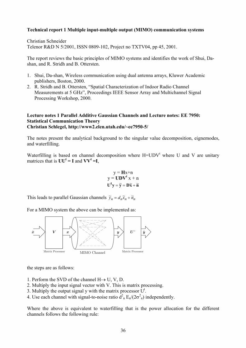
Lecture notes 1 Parallel Additive Gaussian Channels and Lecture notes: EE 7950: Statistical Communication Theory Christian Schlegel, http://www2.elen.utah.edu/~ee7950-5/ The notes present the analytical background to the singular value decomposition, eignemodes, and waterfilling. Waterfilling is based on channel decomposition where H=UDVt where U and V are unitary matrices that is UUt = I and VVt =I,
y = Hx+n y = UDVt x + n
nxDyyUt ~~~ +==
This leads to parallel Gaussian channels nnnn nxdy ~~~ += For a MIMO system the above can be implemented as:
x x y yV U+
Matrix Processor Matrix ProcessorMIMO Channel
the steps are as follows: 1. Perform the SVD of the channel H→ U, V, D. 2. Multiply the input signal vector with V. This is matrix processing. 3. Multiply the output signal y with the matrix processor Ut. 4. Use each channel with signal-to-noise ratio d2
n En/(2σ2n) independently.
Where the above is equivalent to waterfilling that is the power allocation for the different channels follows the following rule:

37
µσ =+ nn E2 and En = 0 when σ2n > µ where each channel has a different noise variance. So in
this case more power is added to the good channel and if the channel is very bad, it is not used at all.
Power level:Differnce µ − σ2n
µ
Channels 1 through N
level: σ2N
Waterfilling: power levels are shown in black. Drawback: the channel H needs to be known at both the transmitter and the receiver so the SVD can be computed. However, channel knowledge is not typically available at the transmitter, and the only choice we have is to distribute the energy uniformly over all component channels. This leads to the Symmetric Capacity. The notes also discuss the Rayleigh MIMO fading channel and shows that it is the expectation as in paper 17 by Holter. Also expressions for large systems capacities are derived. Lecture notes 2 EE359 Wireless Communication fall 2001, Capacity of MIMO Channels - A Survey Anindya Poddar ([email protected]) http://www.stanford.edu/class/ee359/2001/proj2001.html The notes discuss the basic theory of MIMO systems. The ideal case of iid is contrasted with the correlated channel. Water pouring is briefly described. D-BLAST and its decoding are presented as in the book by Da-shan Shiu. Examples of channel matrices with different degrees of correlation are also included. Correlated fading with Channel State Information (CSI), and without CSI at the transmitter are discussed. Space time pre-coding for m by 1 configurations employing either beamforming or transmit diversity are reviewed from paper by E. Vistotsky, U. Madhow, "Space-time transmit precoding with imperfect feedback", IEEE Transactions, Information Theory, vol. 47, no. 6, pp 2632-2639. Results of channel capacity of correlated fading, without channel knowledge at transmitter, are presented from book by Da-shan Shiu. The results of adaptive power allocation as presented by Ivrlac et. al. (VTC fall 01) are also discussed with some reservation as to the validity of the results.
2006 年6月OFDM-MIMO专题 http://www.anywlan.com

38
Paper 18 Effect of antenna separation on the capacity of BLAST in correlated channels Dimitry Chishik, Farrokh Rashid-Farroki, Jonathan Ling, and Angel Lozano, IEEE Communications Letters, Vol. 4, No. 11, November 2000, pp 337-339. The paper discusses the effect of correlation at the transmitter and receiver ends. It gives a modified expression of the channel capacity, which includes the effect of correlation between the antenna elements. The capacity bound is now given by:
+= tc
TRT
HHn
IC φφρdetlog2
where φΤ, φR are the covariance matrices of the transmit and receive arrays, respectively. The entries of the covariance matrices, corresponding to co-polarized antenna are given by the correlation coefficients
ααρφα
dpe ijjkdij )(
)cos(∫
−=
where α is the azimuth angle of incidence, k is the wavenumber, and φ is the angle orientation of the linear array, set to be 90o for the broadside array, p(α) is the pdf of the angle distribution. The capacity equation is obtained by transforming the uncorrelated complex Gaussian channel matrix H to:
Hc = KH Where each entry is ∑=
qppqijpqij hKh
,
Simulations assuming: 1. Gaussian pdf and a uniform pdf of the angle of arrival with 2o rms angular spread, 2. single and dual polarization, 3. 16 by 16 MIMO, 4. 10 dB SNR, 5. The remote (subscriber unit) antenna array elements are assumed uncorrelated. The results indicate that: 1. The Gaussian pdf reaches the higher capacity before the uniform distribution. 2. For a wavelength separation of 4, 80% of the maximum capacity is reached under the
Gaussian spectrum assumption i.e. 32 b/s/Hz in contrast to 42 b/s/Hz. 3. Full capacity is reached at a separation of 10 wavelengths. 4. Dual polarisation requires less separation.
2006 年6月OFDM-MIMO专题 http://www.anywlan.com
39
Paper 19 Keyholes, correlations and capacities of multi-element transmit and receive antennas Dmitry Chizhik, Gerard Foschini, Michael Gans, and Reinaldo Valenzuela, IEEE Transactions on Wireless Communications, vol. 1, No. 2, April 2002, pp 361-367 The paper introduces the idea of keyholes, which might cause the channel matrix to degenerate. The channel matrix is expressed similarly to that given in paper 12, where the entries are uncorrelated but still the channel matrix has only one degree of freedom. The channel entries are no longer Gaussian distributed but each is the product of complex Gaussians resulting in a Bessel function distribution. Examples that might arise in real situations are given. For indoor environment this might arise in propagation in a hallway, which corresponds to single mode, guided propagation. For outdoor environments diffraction over rooftops in the vicinity of the mobile or a tunnel might cause the keyhole effect. Analysis of vertical and horizontal base arrays is given. The rooftop diffracting edge acts as an equivalent horizontal line source with varying current strength along its length. If the base antennas are vertically separated, the richness of the perceived channel is collapsed and a keyhole is formed. Increasing the vertical antenna separation does not remedy the situation but placing the antenna elements in a horizontal array with adequate separation might remedy the situation. Cross polarisation coupling has been reported to be -6 dB and the fading on the two polarisation has been found to be uncorrelated. The capacity is expected to be approximately doubled when dual polarisation is used at both the transmitter and receiver ends. For outdoor environments the angular spread at the base station has been found to be greater when the mobile moved along circumferential roads (2-6o) than for radial streets (1-3o). Simulations with angular spread of 2o were used with equations derived in the paper for the correlation coefficient for a horizontal array. Similar results to those obtained in paper 18 are obtained. That is at 4 wavelength separation 80% of the capacity is achieved. Conclusions: 1. Decorrelation is not a guarantee of BLAST performance. 2. Keyhole situations give rise to entries in the channel matrix, which are the product of two
complex Gaussian distributions. 3. Physical examples of keyholes include a metal screen, a modal keyhole in a waveguide or a
hallway, (when only one mode propagates). 4. For outdoor propagation a keyhole arises at the base station with a vertical array when the
main components get diffracted over a rooftop at the mobile end. This can be remedied by using a horizontal array with adequate separation between antenna elements. The antenna separation of 4 wavelengths is adequate when the scattering region is about 30 m in diameter (about a street width) and the remote is less than 1 km away from the base. For a horizontal array additional scattering from tall buildings would enrich the channel and lead to larger capacities.
5. A similar diffraction keyhole may arise in a microcell with diffraction from a vertical building edge and a horizontal array.
2006 年6月OFDM-MIMO专题 http://www.anywlan.com
40
Paper 20: Experimental verification of MTMR system capacity in controlled propagation environment Hao Xu, M.J. Gans, N. Amitay and R. A. Valenzuela, Electronics Letters 19th of July 2001, vol. 37, No. 15, pp 936-937. The paper describes the results of measurements in the near field carried out with linear horizontal array at the transmitter with 5 elements each with 15o HPBW and 13 dB gain. The separation between elements is 0.52 m. The receiver has both vertical and horizontal elements with 26o HPBW and 15 dB gain. The two arrays form a cross resulting in 7 elements in the cross array. The transmitter was at 35 m above ground and the receiver was raised to 10 m above ground. The measurement was performed at 84 m separation between transmitter and receiver. The heights and separation were chosen to eliminate the reception of the ground wave. The transmitted signal consisted of CW transmissions at 2.44 GHz + (8, 9, 10, 11, 12 kHz). All these five frequencies were received by the seven receivers, down converted, digitised and Fourier transformed to extract the complex coefficients of the channel matrix. A channel model was used to compute the channel coefficients. Results of channel capacity were produced for the supermum (a channel whose matrix is full rank with all singular values equal), a keyhole (H has one degree of freedom or one nonzero singular value), the Rayleigh iid, free space at 83 m theoretical and measured, free space 830 m. The results showed the following capacities in order: Supermum, iid, (Free Space 83 m theory, Free Space 83 m measured) very close, Free Space 830 m and keyhole fairly close. The higher capacity achieved at 83 m in comparison to the 830 m is explained in terms of the curvature of the wave in the near field which results in the coefficients of the channel being different due to the phase difference. In the far field, the plane wave assumption holds and the channel coefficients are now very close in amplitude and phase and the capacity will be close to that of a keyhole. Paper 21: MIMO channel capacity for fixed wireless: measurements and models. H. Xu, M. Gans, N. Amitay, R.A. Valenzuela, T. Sizer, R. Storz, D. Taylor, M. McDonald and C.Tran, VTC 54th Atlantic city, October 2001, pp 1068-1072. The paper describes further results obtained with the setup previously described in paper 20. The first part of the paper gives the same free space model and results of paper 20. In the measurements the transmitter was mounted on a hill at 35 m and the receiver antenna was mounted at 5 m and 10 m. Results of capacity over 16 fixed locations in suburban environments showing the effects of polarization and antenna height are presented for 4 by 5 and 7 by 5 antenna array. Summary of results: 1. The measured capacity ranges from keyhole to Rayleigh iid.
2006 年6月OFDM-MIMO专题 http://www.anywlan.com
41
2. Horizontal array provides higher capacity for the 10 m height indicating a higher angular spread in the horizontal plane than in the vertical plane. At 5 m the angular spread is comparable in both planes due to scattering from clutter.
3. Higher capacities are obtained at lower antenna height because of the scattering effect although the direct path is attenuated causing the total received power to be reduced.
4. The capacity does not increase linearly with the number of antennas. For example for 4 element horizontal array we get 7 b/s/Hz, while for the 7 element we get 8.5 b/s/Hz which is only 20% more. For the 4 by 5 array, 60% of the iid capacity is reached.
Paper 22. Outdoor BLAST Measurement System at 2.44 GHz: Calibration and Initial Results. M. Gans, N. Amitay, Y. S. Yeh, H. Xu, T.C. Damen, R.A. Valenzuela, T. Sizer, R. Storz, D. Taylor, W.M. MacDonald, C. Tran and A. Adamiecki, IEEE Journal on Selected Areas in Communications, Vol. 20, No. 3, April 2002, pp 570-583. The paper describes in detail the system used in the BLAST measurements reported in papers 20 and 21. The paper highlights the importance of calibration. The effects of noise and system non-linearity on the measurement of keyholes are discussed. The 5 transmit elements used in the measurements are separated by 0.52 m and the receive elements are separated by 0.91 m. Seven antenna elements form the asymmetric arrangement. The measurements were taken over 10 ms at a time and recorded every 0.1 s. In each run 300 consecutive channel matrices are saved which take a total of 30 s. The paper describes a calibration procedure for both a free space situation and for a keyhole situation. Results of measurements at 16 locations up to 10.3 km are presented (The same as for paper 21). The results indicate channel capacities greater than 38 b/s/Hz at 20% of the locations and greater than 24 b/s/Hz at 50% of the locations. The power per transmitter was 30 dBm. Presentation 3 Mutliple Antenna Systems: A new wireless communication technology of extra-ordinary bandwidth efficiency for 3G and beyond. R. Valenzuela www.bell-labs.com/user/rav/Internet2.pdf The presentation gives the justification for BLAST; that is the need for higher bit rates at the same bandwidth. It gives a brief background for channel capacity of SISO and diversity techniques and contrasts this with BLAST capacity. It gives graphs of channel capacity versus range for different antenna numbers from 1-16 (assuming n = m). The applicability of BLAST to laptop or palm devices is proposed. The presentation includes slides on the V-BLAST prototype (30 kHz at 1.9 GHz with 12 by 16 antennas). The single position results (of paper 3) of BER and BLER over 10 positions are presented in addition to the outdoor results of the suburban measurements of paper 22. Urban measurements in Manhattan of 16 by 16 array at 2.1 GHz are reported. The measurements parameters are:
42
• horizontal 2x8 array of polarized antennas • 60o HPBW, 4.16 dBi gain, 2 and 4 λ spacing • h t : 100 m. • 16 discrete frequency tones • f c : 2.110 GHz + [4: 32] kHz • P t : 23 dBm/ Ant – Remote: van mounted • 4x4 array of alternating polarizations with laptop profile • 60o HPBW, 4.16 dBi gain, ½ λ spacing • h r : 1.5 m. • 1.5 ms per H or 650 H matrices/ second Capacity results for 10 dB SNR versus distance show that generally the channel capacity is not too far away from the iid case of 43 b/s/Hz with some locations suffering from the keyhole effect. These locations were not frequent. For 4 by 4 antenna configuration the capacity is seen to be 90% of the iid case while for the 16 by 16 it is only 80% of the iid capacity. The results show the following for 16 Tx 16 Rx, high base station • Lower capacity as Tx antennas are brought closer • Measured capacity is a large fraction of capacity of Rayleigh iid channel as shown in tables 1 and 2 below Array Size % of Rayleigh iid 2 Tx 2 Rx 99 % 4 Tx 4 Rx 90 % 16 Tx 16 Rx 80 % Table 1: Results of capacity versus antenna numbers
Array Size Measured mediancapacity(bps/Hz at 10 dB SNR)
Theoretical median capacity(bps/Hz with Rayleigh iid at 10 d
1Tx 1Rx 3.46 3.46
2 Tx 2 Rx 5.8 5.88
4 Tx 4 Rx 10.3 11.1
16 Tx 16 Rx 32 43.7
Table 2: Comparison of measured and theoretical capacity results MIMO in UMTS:
• BLAST (MIMO) technologies proposed to 3GPP standards body for use in high speed downlink packet access.
• Link and system level simulation results show promise of MIMO technologies. • MIMO text has been included in the technical report to be submitted to the March 2001
RAN plenary meeting for approval to become a work item for UMTS Release 5 (scheduled to be completed by March 2002).

43
Link simulations were presented for: -Turbo coding, 3km/ hr, flat fading, known channel, uncorrelated spatial fading Practical considerations for the terminal include: 1. For uncorrelated fading, ½ λ spacing is sufficient because of local scatterers. 2. Each antenna requires RF/ IF chain. Significant cost savings using direct conversion
(homodyne) solutions. 3. 20% and 70% of baseband processing used by V-BLAST detector and turbo decoder,
respectively, for (4,4) receiver. Overall processing is within range of existing hardware technologies.
MIMO in UMTS: conclusions • MIMO achieves high data rates (10.8 Mbps) more efficiently than conventional diversity
techniques (QPSK vs. 64 QAM). • MIMO achieves higher peak data rates (up to 21. 6 Mbps). Future work: • Alternative transmission/ detection/ decoding techniques • Closed loop MIMO techniques • Equalization for frequency selective fading • Reduced- complexity receiver processing Necessary questions to answer: • Need to determine the multipath characteristics of the channel. Large-scale propagation
measurements are under way. • Secondly, given the channel characteristics, what degree of antenna separation is necessary
to obtain good performance? Preliminary results indicate that very small separations suffice at terminals and a fraction of classic diversity separations suffice at the base station. While research continues at an accelerated pace, BLAST is already being introduced into the standards for mobile 3G systems (UMTS, EDGE) as well as indoor systems (WLAN).
Paper 23 Multiple input multiple output measurements and modeling in Manhattan D. Chizhik, J. Ling, P. Wolniansky, R. Valenzuela, N. Costa and K. Huber, IEEE Journal on Selected Areas in Communications, April 2003, Volume 21, Number 3 MIMO SYSTEMS AND APPLICATIONS: PART I Also presented at the VTS 56th Vehicular Technology Conference, VTC 2002, Vancouver Narrowband MIMO measurements using 16 transmitters and 16 receivers at 2.11 GHz were carried out in Manhattan. Capacities were summarized in presentation 3. In this paper correlation model parameters are derived from data. The model used is the iid channel matrix, which is modified by the correlation matrices at the transmitter and at the receiver:
2/12/1TiidR HH φφ=
where φR,Τ are the correlation matrices.

44
Correlation matrices were computed and used to filter the synthetically generated H matrix. The capacities from the measurements and the predictions were compared. They were generally found in agreement except for one location, which is akin to a keyhole. CDF of channel capacity statistics were found to be well represented by the separate transmitter and receiver correlation matrices, with a median relative error in capacity of 3%, in contrast with the 18% median relative error observed by assuming the antennas to be uncorrelated. For 16 by 16 MIMO system, the correlation matrices at the transmitter and at the receiver are 256 element each. To reduce the computations, a 4 parameter model was found. For the transmitter end, it was found that the correlation exponentially decayed with antenna separation. At the receiver the correlation coefficient was found to remain constant irrespective of the antenna separation. Using the coefficients for the two polarizations, four parameters can be found. The spatial channel model reported allows simulations of H matrices for arbitrary antenna configurations. These channel matrices may be used to test receiver algorithms in system performance studies. The results may also be used for antenna array design, as the decay of mobile antenna correlation with antenna separation has been reported here. An important finding for the base transmitter array was that the antennas were largely uncorrelated even at antenna separations as small as two wavelengths. Paper 24 On the capacity formula for multiple input-multiple output wireless channels: a geometric interpretation P.F. Driessen and G.J. Foschini, IEEE Transactions on Communications, vol. 47, No. 2, February 1999, pp 173-176. The paper uses raytracing to find the capacity for different antenna configurations for LOS channels and Rician channels. For LOS situations (free space) no fading, the coefficients of the channel matrix are of the form:
( )ki
kiij RT
RTjRTH
−−−
−=λπ /2
exp)( 11
where T's and R's are the coordinate vectors for antennas, T1 and R1 are the reference locations so that H1,1 = 1 and the absolute attenuation need not be calculated. If the antenna separation is less than half a wavelength for both antenna arrays, the channel coefficients are all equal since the phases are nearly the same. Hence the channel capacity reduces to:
)1(log2 ρnC += That is the channel matrix H for LOS situations is of rank 1 and the capacity gain is essentially due to the n fold array gain. For large antenna separation the amplitude of the coefficients are the same but the phases are different giving HHtc =nIn, H of LOS is of rank n, and
C = n log2 (1+ρ) The above capacity equation is seen to hold for the following antenna geometry: 1. Linear arrays at the transmitter and at the receiver with the broadsides facing each other.
45
2. Transmitter array on arc of radius >> wavelength, and receiver array linear with broadside facing centre of arc.
3. Transmitter array spread evenly on circle with radius >> wavelength, and receiver array on a circle of radius < wavelength at the centre of the transmitter array.
4. A street canyon with linear arrays with λ/2 spacing oriented perpendicular to the street. This relies on the reflections from images.
For the Rician channel, the coefficients can be divided into two parts one corresponds to the LOS and the other to the Rayleigh fading component that is H = aHLOS+bHRayleigh with a2+b2 =1 and the Rician factor K= a2/b2. Simulations were carried out for different values of K. When the antenna spacing is less than a wavelength, the capacity reduces to that of the LOS with one degree of freedom (rank 1). For the array geometry as described above when H LOS is of rank n, the capacity increases with increasing K. The paper proposes that to obtain high capacities for Rician channels, use the following: Spread out the elements of the array either explicitly by transmitting from different locations or implicitly by adding reflectors to create images. Paper 25: Capacity of multiple antenna system in free space and above perfect ground P. Kyritsi and D. Chizhik, IEEE Communications Letters, Vol. 6, No. 8, August 2002, pp 325-327. The paper examines the channel capacity of a free space environment with over ground reflection. The arrays are assumed to be isotropic without mutual coupling and known polarisation. Analytical expressions are given for propagation with ground reflection for horizontal and vertical polarisation. Experiments were carried out in a parking lot with 12 by 15 element arrays at 1.95 GHz. The arrays were flat, folded cavity backed slot antenna elements mounted on a 2 foot by 2 foot panel, with vertical or horizontal polarisations arranged on a 4 by 4 grid separated by λ/2. Two heights above ground were examined (2 m and 12 cm) with antenna separations of 1, 1.5, 2, 5, 10 and 15 m. The system bandwidth was 30 kHz. The results show that the capacity decreases with distance as is predicted by the theory. For Gaussian iid the capacity is 72 b/s/Hz for a 12 by 15 array. The measurements show that the capacity for array separation less than 6 wavelengths gives capacities higher than 72 b/s/Hz. Paper 26 Information capacity of a random signature multiple input multiple output channel, P.B. Rapajic and D. Popescu, IEEE Transactions on Communications, Vol. 48, No. 8, August 2000, pp 1245-1248. The paper gives closed form expressions for the channel capacity where the multiple inputs come from different CDMA users thus with random signature. The analysis is carried out for two cases: K<N that is the unsaturated system and for K>N (over-saturated system) where N is the rank of the channel matrix and K is the number of users.
2006 年6月OFDM-MIMO专题 http://www.anywlan.com
46
The results are applicable to CDMA systems where the different users are the multiple transmitters and the antennas at the base station form the multiple receivers. Paper 27 Spatial and temporal variation of MIMO channels and impacts on capacity Xu, Gans, Chizhik, Ling, Wolniansky, and Valenzuela, IEEE Proceeding International Conference on Communications, New York, pp 262-266, May 2001, ISSN 0-7803-7400-2/02 The paper presents results of measurements in Manhattan at 2.11 GHz using 16 by 16 narrowband channel sounder. Expressions for temporal and spatial correlation are given. Also the Doppler spectrum is used to derive an expression for the probability density function of the angle of arrival. This in turn is used to estimate the rms spread of the AOA. A modified expression for the channel capacity including the correlation at the transmitter and at the receiver is given with simulations for a 4 by 4 system in correlated channels. The configuration of the system assumed linear arrays at both ends with 4 λ at the base and 0.5 λ at the mobile. These configurations are currently under discussion in 3GPP MIMO Ad-Hoc group. Uniform angular distribution is used at the mobile with the angular sector width varying from 0 to 180o. The results show that the correlation decreases as the uniform AOA sector increases resulting in greater capacity. At the sector width of 72o the correlation coefficient drops to 0.5 and the median capacity reaches 10 b/s/Hz which is only 1 b/s/Hz less than the median capacity for a 4 by 4 system in an ideal Rayleigh iid channel. Further increase in angular sector width at the mobile does not increase the capacity. For a 4 λ spacing and 10o of angular spread at the base the transmitter antennae are essentially uncorrelated. The measurements used slot antennae with vertical polarisation and 78o beamwidth whilst the horizontally polarised antennae had uniform gain from 0 to 180o. The different antennae were distinguished by using frequency tones separated by 2 kHz. The receiver samples the 16 receiver chains simultaneously at 78125 Hz. The different tones are identified using the FFT. The channel update rate is 1.5 ms. Measurements were collected at two base station heights of 100 m and 30 m. The mobile receiver was mounted on the side of the van, which moved within the sector covered by the base station antennae. The range covered was from 500 metre to 2 km. Correlations were calculated by averaging over 40-50 wavelength which correspond to 6-7.5 m in distance or 0.6-0.75 s in time at a mobile speed of 10 m/s or 36 km/hr. For 0.5 correlation coefficient the median correlation distance is close to 0.5 wavelength which is twice the distance predicted by Jake's model. This gives a correlation time of 0.1 s. However the horizontal polarisation gives higher correlation distance/time. The angular spread for the horizontal polarisation antennae is about 22.5o, which is slightly lower than the 25.5o for the vertical polarisation. The angular spread 25o corresponds to a sector width of 86.6o with a uniform distribution of AOA in a continuous sector. In conclusion the non-uniform angular spread is not seen to reduce the channel capacity since the spread is wide enough. However the increased correlation time can be used to optimise the update frequency for equaliser taps, rake finger searching or the channel estimation.

47
Paper 28 Capacity of MIMO Systems Based on Measured Wireless Channels A. F. Molisch, M. Steinbauer, M. Toeltsch, E. Bonek, and R. S. Thomä, IEEE Journal on Selected Areas in Communications, Vol. 20, No. 3, April 2002, pp 561-569. In this paper a new procedure that allows the evaluation of the cumulative distribution function (cdf) of the capacity from a single MIMO channel snapshot is presented. It is based on the determination of the directions-of-arrival (DOAs), direction-of- departure (DODs), and delays of the multipath components, coupled with a synthetic variation of their phases. The method is applied to measurements at 5.2 GHz both for the frequency-flat fading channel and the frequency-selective channel. From this the following are derived: a) results for the capacity of frequency-flat channels in microcellular environments, and the
effects of the number of antennas, and other parameters; b) results for frequency-selective channels, which show how the mean capacity and outage
capacity are improved as the bandwidth is increased. The measurements were done with a RUSK ATM channel sounder with a bandwidth of 120 MHz, connected via a fast RF switch to a uniform linear receiver antenna array. This array consisted of antenna elements (+ 60o element-beamwidth), plus two dummy elements at each end of the array. For simplicity, a virtual array was used at the transmitter. It consisted of a monopole antenna mounted on a X–Y-positioning device with stepping motors. The positioning was controlled by a personal computer (PC) via a serial RS 232 interface. 16 transmit antenna positions were used in a cross (8 on each axis). One complete measurement run (2 by 8 antenna positions at TX times 8 spatial samples at RX times 192 frequency samples and 256 temporal samples gives 16 ×8× 192× 256 = 6,291,456 complex samples) took about 5 minutes. To assure the time-invariance during that period, they used two procedures: the first one was a Doppler-filtering procedure. Secondly, they performed measurements in the same location three times at intervals of about 5–10 minutes, and compared the results. Two advantages of the virtual array-technique: 1) it is more versatile than the physical-array arrangement; and 2) there is no mutual coupling to neighboring elements, so that no calibration is required. The data were processed using Unitary EPRIT for the estimation of the channel parameters. Subsequently the channel capacity was estimated from an ensemble realised by changing the phase using a uniform distribution where the channel coefficients are given by
( ) ( )[ ] ( ) ( )∑
−×+−=
iiiiTiRimk jfjmkdjafh ατπφφ
λπ exp2expsinsin2exp)( ,,,
where αi is a uniformly distributed random phase, which can take on different values for the different MPCs numbered i, and it stays unchanged for the different antenna elements. For the flat-fading case, τi = 0. For the frequency selective channel the capacity is given by
∫
+= dfff
NBC tc
T
)()(detlog12 HHI ρ
The CDF results were compared with the movement of the transmitter array first synthetically i.e. in simulations and secondly via measurements (only 8 measurements were taken). The results show that the measurements gave higher capacity than the synthetic movement of the

48
array. This was attributed to the power of the multi-path components being underestimated by the unitary ESPRIT algorithm. Results: The investigated scenarios were two courtyards with and without LOS. The derived channel parameters were used to compute the channel capacity for a 4 by 4 system with 20 dB SNR. (The paper does not specify whether the antennae were omni directional or had the same characteristic as those used in the measurements). The capacity was found to be on the order of 11-16 b/s/Hz as compared to 18 b/s/Hz for the iid channel. The LOS capacity was found to be smaller than the NLOS for the same SNR. The capacity was found not to increase as the antennae separation was increased. This was attributed to the insignificance of the de-correlation via the phases. Rather the more significant factor was the number of multi-path components and their relative amplitude. This was confirmed by simulating the same channel with similar amplitude for the multi-path components, which resulted in a channel capacity equal to the ideal iid channel. In the wideband case the capacity for the LOS scenario was found to improve from 13.6 b/s/Hz to 14.2 b/s/Hz as the bandwidth increased to 100 MHz (13.8 b/s/Hz for 10 MHz). The paper refers to the theoretical work of H. Boelcskei, D. Gesbert, and A. P. Paulraj, “On the capacity of OFDM based multi-antenna system”, 2000 submitted for publicaion which has shown that, in MIMO systems, the frequency selectivity of the channel can increase the mean capacity. Increases upto 30% were predicted for certain channel situations. However, the measurements reported in the paper, only showed a small change in the mean capacity as the bandwidth increased i.e. as the frequency selectivity increased. Specifically, the increase was always less than 10%. This was attributed to the fact that the scatterer distribution in the studied scenarios differed appreciably from the one assumed in the work of Paulraj. Finally, the paper investigates the improvement of the outage capacity by frequency diversity as a function of the array size. It was found that both the relative and the absolute improvement decreased as the number of antennas increased. The reason for this behavior is that the additional antennas already provide some degree of diversity, so that the additional frequency diversity becomes less important. Paper 29 MIMO wireless channels: capacity and performance prediction D. Gesbert, H. Bolcskei, D. Gore, and A. Paulraj, IEEE Globecom 2000, San Fransisco, CA, vol. 2, Nov. 2000, pp 1083-1088 http://heim.ifi.uio.no/~gesbert/papers/globecom00.pdf The paper gives a channel model, which takes into account the correlation at the transmitter and at the receiver arrays. It also introduces another factor, which can be used to interpret the effect of keyholes. Therefore the channel model can be used to represent: • uncorrelated high rank (UHR) also known as iid channels, • uncorrelated low rank (ULR) i.e. key holes where every realisation of the channel matrix has
rank 1 which can give diversity gain but no increase in capacity due to the multiple antennas at the transmitter,
• correlated low rank (CLR) MIMO channel,
2006 年6月OFDM-MIMO专题 http://www.anywlan.com
49
• 1 by 1 uncorrelated high rank (HR) i.e. UHR with M=N=1, Rayleigh fading, and low rank (LR) i.e. ULR or CLR with M=N=1, double Rayleigh.
The model assumes the number of scatterers to be greater than 10 and the effect of remote scatterers is negligible so there are two scattering rings one at the transmitter with radius Dt and another at the receiver with radius Dr and the separation between them is R. The channel matrix is then represented by:
2/1/2,
2/12/1,,
1SDtr rstdtrdrS θθθ RGRGRH =
where the first two R's are the correlation matrices at the receiver and at the transmitter respectively and the G's are iid matrices at the receiver (M by S) and transmitter (S by N) with the given angular spreads and the antenna spacing (M,N,S are the number of transmit antennas, receive antennas, and scatterers, respectively). These two R's are governed by, the angular spread, the antenna spacing and the beamwidth, which become rank deficient for highly correlated arrays. The last term is due to the scatterers and depends on the scatterers angular spread where tan(θs/2)=Dt/R, the diameter of the receiver spreading area and the range between the transmitter's and receiver's scatterers. The above equation shows that the channel matrix can become rank deficient if any of the R's becomes rank deficient due to correlation at the transmitter or receiver or due to the last term becoming rank deficient. This occurs when DtDr <<R (the range), making the scattering angle θs small. Hence, in the main the rank of the matrix is governed by, the range and the scattering radii. If the scatterers are absent at one end, the rank at that end is governed by the antenna separation. If the angular spread is also small the rank of the relevant matrix also drops resulting in loss of antenna diversity and spatial multiplexing capacity leaving only the antenna gain. Note that the product of G's approaches a single Rayleigh matrix, which justifies the traditional channel model when there is no correlation at either end and the scatterers lead to full rank. Monte Carlo ray tracing simulations were carried out to verify the model. The results show that as R (range) is increased the channel goes from UHR to ULR illustrating the effect of the scaterrers on the capacity. Paper 30 Dynamic capacity estimation for the indoor wireless channel with MIMO arrays and pedestrian traffic K. Ziri-Castro, W. G. Scanlon and F. Tofoni, http://telecoms.eeng.dcu.ie/symposium/papers/C2.pdf The paper presents a model for MIMO channels, which takes into account the movement of people in an indoor environment. The model is based on geometrical optics and a detailed radar cross-section representation of the human body. The ray-tracing components of the model takes the radiation pattern of the transmitting and receiving antennae including the direction of rays at the transmitter and receiver, the path length, the multi-path, the transmitted power and the reflection coefficient. It uses FDTD modelling image-based ray-tracing and detailed radar cross-section modelling of a realistic human body phantom.
2006 年6月OFDM-MIMO专题 http://www.anywlan.com

50
The model was applied to a single room with 7 m by 6 m. The MIMO system consisted of two linear arrays with half wavelength dipoles spaced at 0.4 wavelength and 8 elements each. The simulations were carried at 2.45 GHz assuming a narrowband signal. The room height was 2.75 m and the transmit antenna height was 1.95 m and the receive antenna height was 1 m. Simulations with 1 and 2 pedestrians crossing the path of the arrays showed that when the LOS is obstructed the signal strength is reduced and the capacity increased from 19.1 b/s/Hz to 31.4 b/s/Hz at 16 dB SNR. Paper 31 Performance limits in fading MIMO channels B. Paulraj, D. Gore, and R. Nabar, WPMC 02, October 27-30, 2002, Hawaii, pp 7-11 The paper discusses the effect of the variations of the channel capacity on the packet error rate when the transmitter does not have knowledge of the channel matrix to adjust its transmission rate but only knows the SNR. It presents simulations (iid channel assumed) for outage packet error rate (PER) vs SNR for fixed 6 b/s/Hz. The SISO channel is seen to suffer from errors as long as the SNR is less than 18 dB whereas the PER decreases as SNR increases for a 2 by 2 MIMO channel. The results show that a tradeoff exists between PER and SNR by a factor equal to the diversity order (M by N). The paper also compares the performance of different coding schemes and shows that the OSTBC (orthogonal space time block codes) data stream, which then uses the Alamouti scheme is worse than the spatial multiplexing with horizontal encoding with MMSE receiver, for SNR less than 18 dB and then it reverses. In the first, the data are optimally SISO encoded and then transmitted using the Alamouti scheme. In the second, the data are de-muxed and then coded optimally before transmission. Paper 32 double-directional radio channel estimation at 2 GHz for high speed vehicular mobiles-experimental results H. Hofstetter, M. Steinbauer, C.F. Mecklenbrauker [email protected], http://www.ftw.at The paper presents results of double-directional measurements obtained at high vehicular speeds (160 km/hr) on a race track at 2 GHz using a circular array at the transmitter (15 monopoles mounted on a ground plane spaced at 0.43 wavelength = 6.45 cm resulting in a diameter of around 30 cm in the middle of the 90 cm ground plane) and a uniform linear array with 8 patch elements spaced at a distance of 0.5 wavelength = 7.5 cm at the receiver. In the measurements the transmitter was mounted in the moving vehicle. Each measurement took 0.25 s where the duration of each impulse response is 3.2 µs. The DOA and DOD were estimated by a conditional maximum-likelihood estimator. Three paths were identified both in the LOS and NLOS case. The angular spread was seen to be small.
2006 年6月OFDM-MIMO专题 http://www.anywlan.com
51
Paper 33 Double directional superresolution radio channel measurements H. Hofstetter, C.F. Mecklenbrauker, and M. Steinbauer, http://www.nt.tuwien.ac.at/mobile/papers/mobile_radio_channel/Allerton_Bo/paper.pdf The paper describes double directional measurements obtained with the RUSK sounder at 2 GHz and 5.2 GHz. The 2 GHz measurements are those reported in paper 32. The 5 GHz measurements were taken in the courtyard of Ilmenau University. These used a synthetic array at the transmitter, spanning 8 by 8 cross and a uniform linear array at the receiver with a beamwidth of 120o. The paper describes the signal processing used to extract the DOA and DOD from the transfer function of the channel. Two methods are described. The first uses the 1D unitary ESPRIT in nested loops. Prior to the application of unitary ESPRIT the data are filtered to remove the Doppler shifted components. The second method exploits the shift invariance of ESPRIT in parallel over the different domains. Two new parameters are defined. The 5 GHz measurement when analysed for DOA and DOD did not identify all the components due the large number of scatterers and trees. Paper 34 double directional channel measurements E. Bonek and M. Steinbauer, 11th International Conference on Antennas and Propagation, 17-20 April 2001, pp. 226-230 The paper introduces the concept of double directional measurements. The measurements reported in the paper are the 5.2 GHz measurements described in paper 33. The model used assumes a channel impulse response, which is a function of time delay, angle of departure and angle of arrival. The paper argues the advantages of double directional measurements. These include the ability to simulate the channel excluding the antennas used in the measurements, the ability to test previous channel models such as the single bounce model, a better understanding of the propagation mechanisms, and the ability to predict the capacity of MIMO systems by introducing random phase variations as was subsequently reported in paper 28. Paper 35 MIMO vector channel sounder measurement for smart antenna system evaluation R. S. Thoma, D. Hampicke, A. Richter, G. Sommerkorn and U. Trautwein European Transactions on Telecommunications, ETT, Vol. 12, No.5Special Issue on Smart Antennas, September/October 2001, pp 427- 438, www-emt.tu-ilmenau.de/WWWdocuments/ downloads/paper/2001-002.pdf The paper discusses the advantages of MIMO measurements and gives the basic principle of sequential MIMO channel sounding as applied in the RUSK sounder. It discusses the main channel parameters that can be extracted from such measurements. These are the Doppler shift, time delay, angle of arrival in azimuth and elevation, angle of departure in azimuth and elevation. The path weights include the two orthogonal polarisation responses of the transmitter and receiver antennas and the cross polarisation coupling. The processing of the data using ESPRIT (Estimation of Signal Parameters via Rotational Invariance Techniques) is discussed in relation to different antenna array configurations, which include uniform linear array, uniform rectangular array, circular uniform beam array (CUBA), and stacked CUBA. The advantages and disadvantages of the different arrays are also discussed in terms of their angular resolution,

52
and the processing. The problems associated with antenna arrays such as mechanical and electrical manufacturing tolerances, amplitude and phase mismatch in antenna feeding, finite size effects, parasitic coupling between antenna elements, and cross polarisation coupling are highlighted. The need for calibration with known sources in an anechoic chamber is stressed. An example of DOA, DOD, time of arrival is presented. The application of the channel parameters to MIMO link simulation is discussed and the principle of multi-user SIMO measurements and simulation is also presented with results of bit error rate. The computation of channel capacity of MIMO systems as presented in paper 28 is proposed. Presentation 4 MIMO measurement and joint M-D parameter estimation of mobile radio channels R. Thoma, A. Richter, D. Hampicke, G. Sommerkorn, University of Ilmenau The presentation gives a summary of paper 35. An example of a measurement carried out in the courtyard of Ilmenau (paper 33) where the following parameters were resolved: delay, Doppler, base station azimuth, base station elevation, mobile station azimuth, base station elevation, and vertical to vertical path weights. The following advantages are listed: 1. Double directional channel analysis 2. Remove antenna influence from measurement 3. Enhanced resolution capability 4. Detect multiple reflections 5. Prerequisite for measurement-based deterministic channel modelling. The basis for statistical channel simulation is presented as follows: 1. Estimate the time-variant M-D channel model (the 7 parameters previously mentioned) 2. Reconstruct the electromagnetic field at the transmitter and receiver antenna aperture 3. Calculate transmitter and receiver antenna array outputs from the reconstructed field
corresponding to some predefined antenna array architecture 4. Introduce realistic local movements The advantages of such a technique include: 1. No site specific geometrical database required 2. No formal geometric and static assumptions made 3. Requires low storage capacity 4. Antenna aperture, time and frequency domain can be associated 5. Controlled accuracy by channel sounder dynamic range and resolution 6. Almost arbitrary antenna array architectures 7. Static generalisation in terms of local trajectory (from a single CIR record an ensemble can
be constructed). 8. Large scale variation results from measurement, small scale variation results from the
'animation of the model'
2006 年6月OFDM-MIMO专题 http://www.anywlan.com
53
Paper 36 Outdoor MIMO wireless channels: models and performance prediction D. Gesbert, H. Bolcskei, D. Gore, and A. Paulraj http://heim.ifi.uio.no/~gesbert/papers/mimo_final.pdf IEEE Trans Communications 2002 The paper gives an outdoor channel model similar to the one given in paper 29. The paper adds a section on LOS (also called the green field). In this case two linear arrays are assumed with bore sight propagation. The spatial signature is imposed by the phase of the array. When the phase difference between consecutive elements approaches 0 the channel matrix approaches the all 1 matrix and therefore has rank 1. This happens when the range between the transmitter and receiver is large. As the range decreases linear independence between the signatures starts to build up. For orthogonality the following condition must be satisfied
MRdd rt λ
≥
where the d's refer to the antenna separation, R range between transmitter and receiver, M number of receive antennas. In a pure LOS situation orthogonality can only be achieved for very small values of R. for example at 2 GHz with M = 3 a maximum of R = 20 metres is acceptable for 1 metre antenna spacing. Note that linear independence is necessary but not sufficient for the global channel matrix to have full rank. For the NLOS case the above condition becomes
MRMNDD rt λ
≥−− )1)(1(
22
this formula predicts the high rank region to start at 23 metres of scattering radius for a 10 km range, 3 transmit 3 receive antennae 10 dB SNR, d's=3 wavelength where the wavelength is equal to 0.15 metre. The authors suggest that high capacity can be attained easily even for large range as capacity builds up with scattering. This they suggest explains the high capacity obtained in urban and suburban environments where key holes were not detected. (refers to measurements reported in next paper). Paper 37 Capacity obtained from multiple input multiple output channel measurements in fixed wireless environments at 2.5 GHz V. Ecreg, P. Soma, D.S. Baum, A.J. Paulraj www.nari.ee.ethz.ch/commth/pubs/ viewpub.php?ident=ESBP02 Two by two MIMO measurements at 2.48 GHz conducted in the San Francisco Bay are reported. These were carried out using a coherent 4 x 3 MIMO channel measurement system based on swept frequency sounding. A narrowband test signal was swept in 200 kHz steps across a 4 MHz frequency band every 84 ms. The narrowband receiver was swept synchronously with the transmitter, with timing references derived from rubidium clocks. In the measurements, a dual-polarized receive antenna with slanted polarizations (co-located +/-45°), a gain of 12 dBi and an azimuthal beamwidth of 90° was used. It was mounted on a retractable mast at a 3 m height. The +45° and -45° polarization transmit antennas separated by 10 wavelengths were also directive with an azimuthal beamwidth of 90° and a gain of 17 dBi. The transmitter was located on top of an office building with an antenna height of nearly 20-m above the street level.

54
Fixed outdoor measurements at 40 locations with the receiver located at the curbside were conducted in the Bay Area. At each location two measurements 1 m apart were taken giving a total number of 80 measurements. Each measurement was taken over a 5- minute time interval in the direction of the strongest signal, which turned out to be the direct transmitter-receiver path in most cases. The terrain can be characterized as mostly suburban and flat with a moderate tree and building density. The average building and tree height is about 15 m. The separation distances between the transmitter and receiver were in the 0.2 - 7 km range. The measurements gave narrowband complex channel frequency responses H(f,t). At each frequency and time instance the normalized Ricean 2 x 2 MIMO channel matrix H can be written in terms of a fixed matrix and a correlated Rayleigh matrix which can be obtained from an iid matrix by including the correlation of H similar to paper 4.
+
+
+=
++
+=
22212
12211
X
11
1
11
1
2221
1211
XXX
Keeee
KK
KKK
jj
jj
αα
φφ
φφ
vF HHH
where Xij are correlated zero-mean, unit variance, complex Gaussian random variables of the Rayleigh matrix Hv; exp(jφij) are the elements of the fixed matrix HF; αi are the factors due to XPDs, and K is the temporal Ricean K-factor that determines the ratio of the fixed and variable power components defined as K = |m|2 / ( 2 σ 2 ), where |m|2 is the power of the fixed and 2σ 2 the power of the variable component. The temporal K-factors determined from the experimental data at each tone were estimated from the received signal power versus time (5 minute time intervals). The XPD is defined as the ratio of the mean power received by an antenna with equal polarization orientation as the transmit antenna to the mean power received by an antenna with cross polarization orientation to the transmit antenna. Based on the estimated matrix K-factor, which is defined as the averaged K-factor over frequency and 4 sub-channels of the matrix, the experimental data were separated into three groups: 1) Locations with close to Rayleigh fading characteristic having K-factors < 0 dB, 2) Locations having medium K-factors in the 0 dB to 10 dB range, and 3) Locations having high K-factors in the 10 dB to +infinity dB range. Three different channel matrices were proposed for the Monte Carlo simulations with corresponding envelope correlation coefficients and K factors:
1. Rank 1(low capacity bound)
=
=
2221
1211
X X X
;1 11 1
XvF HH
90-th percentile envelope correlation coefficient was used and low matrix K factors. 2. High XPD (orthogonal columns)
2006 年6月OFDM-MIMO专题 http://www.anywlan.com

55
=
=
22
11
X 00 X
;1 00 1
vF HH
50-th percentile envelope correlation coefficient, and mid-value K-factors. 3. Full rank matrix (upper bound)
=
=
2221
1211
X X X
;1 jj 1
XvF HH
10-th percentile envelope coefficient and high K-factors. The standard deviation of the frequency variation of the envelope correlation coefficients at each location was found to be in the 0.05 to 0.15 range with 0.1 mean value. For 90% of the cases, the envelope correlation coefficients were found to be less than 0.32, 0.42, and 0.42 for transmit, receive, and cross-correlation, respectively. The experimental results were compared with simulations. It was concluded that for the 1. Low K factor: XPD = 0 dB, and K= 0 with a statistical representation of the fading envelope
correlation coefficient can be used to model this case (Rayleigh channel). 2. Medium and high K factor: the results fell between cases 1 and 2 above. Also the condition number, which is equal to the ratio of the maximum to the minimum eigenvalues of H was used as an indicator of channel capacity. The lower is the condition number the better is the channel for MIMO systems. The experimental results were found to fall between the lower and upper bounds of capacity. The results were computed for 15 dB SNR. Paper 38 Multiple-input multiple output (MIMO) wireless systems H. Bolcskei and A.J. Paulraj The Communications Handbook, 2nd Edition, J. Gibson, Ed. pp 1-22 The paper discusses the benefits of MIMO systems which include diversity gain and multiplexing gain. The different types of diversity: time, frequency, and spatial diversity are briefly described. The diversity gain of a MIMO system is pointed out to be higher than SIMO diversity by a factor equal to the number of transmit antennae. The difference between transmit and receive diversity is highlighted. Receive diversity needs signals that fade independently and is independent of coding/modulation schemes, transmit diversity needs special modulation/coding schemes. Also receive diversity gives array gain whereas transmit diversity does not provide array gain when the channel is unknown at the transmitter. The paper then describes MIMO systems and gives the expressions for the channel capacity for the deterministic case and for the random case assuming iid channel matrix. It then briefly describes the main types of receivers that can be used to recover MIMO data. These include the zero-forcing receiver, which mainly aims to invert the channel matrix. It points out that this type of receiver gives perfect separation of the signals at the cost of noise enhancement. In the case of a rank-deficient matrix the receiver multiplies the received signal by the pseudo-inverse of the channel matrix to recover rank (H) data streams.
56
The equation for the minimum mean-square error receiver (MMSE) is given. It is pointed out that this type of receiver minimises the overall error due to noise and mutual interference between the signals. The steps of the receiver used in V-BLAST are described, nulling, slicing, and cancellation where first the strongest signal is detected, then cancelled out from the data stream and this is then repeated i.e. determine the strongest signal using ZF, null out all the other signals, detect the strongest, re-modulate it and subtract it from the overall received signal and repeat. Maximum likelihood receiver is identified as giving the best performance in terms of error rate but has the highest complexity. Finally indirect and direct transmit diversity are discussed. The described forms of indirect diversity are: delay (converts spatial diversity into frequency diversity), and intentional frequency diversity (converts spatial diversity into time diversity). Described direct diversity techniques are: space-time block coding using the Alamouti scheme and space-time trellis codes. Paper 39 MIMO a solution for advanced wireless access M.A. Beach, D.P. McNamara, P.N. Fletcher and P. Karlsson ICAP 2001, Manchester, pp 231-235 The paper contains a review of MIMO principles including a brief description of the BLAST architecture: vertical and diagonal BLAST. Two types of space-time coding are also described: the Alamouti encoder and the delay diversity transmission schemes. The paper gives a substantial number of references (31). Paper 40 Systemes de communications multi-antennes influence du canal de propagation P. Guguen, P. Lopez, and G. El Zein, 4em Journees d’etudes Propagation Electromagnetique dans l’atmosphere du decanetrique a l’angstrom, Rennes, 13-15, March 2001, session 6. The paper gives the background of MIMO systems and classifies the different types of diversity according to the type of dispersion imposed by the radio channel. Hence three types of dispersion are identified: time delay (frequency coherence), Doppler spread (time coherence), and wave vector (spatial coherence). The paper gives a signal model in terms of the sum of the received signals from all the transmit antennae. Channel models are discussed: statistical models including the effect of correlation at the transmitter and receiver and geometric models. It proposes that the number of degrees of freedom is proportional to D/Dcoh where D is the size of the antenna network and Dcoh is the coherent distance. If the ratio is approximately equal to 1 the network is completely coherent. If the ratio is equal to N then the network has N degrees of freedom. Accordingly it is possible to have four possibilities for a MIMO system. In the worst case both the transmitter and receiver has a ratio of 1 in which case there is no diversity gain as both the transmitter and receiver are completely coherent. When one end, either the transmitter or receiver has N degrees of freedom then it is possible to have a diversity link. When both ends are not coherent, and each provides N degrees of freedom where N is the minimum of transmit, receive antennae then it is possible to have a MIMO system.

57
The paper also differentiates between spatial multiplexing techniques (BLAST, spatial multiplexing, high diversity modulation etc..) and diversity techniques such as space time coding. The difficulties in equalising the frequency and time variations are highlighted. Simulations of capacity for a four by four system for different angular spreads at the transmitter and receiver and different wavelengths are presented. They identify two regions: a region where the antenna spacing and angular spread are sufficient to give high capacity, and another region where capacity is low since the system is operating in the coherent region. The paper gives several references particularly those relevant to space time coding. Paper 41 Detection algorithm and initial laboratory results using V-BLAST space-time communication architecture G.D. Golden, C.J. Foschini, R.A. Valenzuela and P.W. Wolniansky, Electronics letters, 7 January 1999, volume 35, number 1 The paper gives a description of initial laboratory results of V- BLAST using 4 transmit antennae and 6 receive antennae. It also gives the steps for extracting the data stream from the received signal. Laboratory results show that a channel capacity of 25.9 b/s/Hz. The paper is a short version of paper 3. Chapter 9 MIMO channels, pp 233-265, Space time wireless channels, G. Durgin, Prentice Hall The chapter gives a review of channel capacity of different types of systems using multiple antennas at the transmitter and/or at the receiver. It starts with SISO channels, SIMO channels and MISO channels. It distinguishes open space (no multi-path) and multi-path situations. In the case of SIMO channels this distinction differentiates antenna gain and diversity gain. In the case of MIMO channels it uses the singular value decomposition and proposes a physical explanation for MIMO channels where the transmitter has knowledge of the channel resulting in a double directional system where, each received signal is reflected by a different scatterer. The author warns of the danger of this over-simplification. The effects of correlation and key-holes on channel capacity are mentioned. Figures showing the effect of the Rician channel on capacity are given. The extraction of the data using the zero forcing technique i.e. matrix inversion is presented followed by the interference cancellation method used in V- BLAST. Also D- BLAST is briefly described. Space-time coding is introduced where the Alamouti coding scheme is presented as transmit diversity scheme. The chapter is clearly written although it is rather too brief. Paper 42 Multiple input multiple ouput (MIMO) radio channel measurements C.C. Martin, J.H. Winters, N.R. Sollenberger, VTC2000, ISSN 0-7803-6507, pp 774-779. The paper describes a measurement campaign using a 4 by 4 MIMO system. The field tests were conducted with four antennas attached to a laptop. The antennas were either vertical monopoles or dual polarised with half wavelength spacing. The laptop was placed in a van and

58
used as the transmitter where each channel transmitted 1 W. The receiver used dual polarised antennas with + 45o slant, which were separated by 20 wavelengths and were placed on the rooftop in a suburban environment. The measurement system used orthogonal Walsh codes with 8 symbols at 24.3 k symbol/s in 30 kHz bandwidth as in the IS-36 system. For a 4 by 4 antenna this should provide the possibility of increasing the bit rate to 1.5 Mbps from the 384 kbps of the EDGE system. The carrier frequency was 1900 MHz and a channel response was obtained every 300 µs. All the four received channels were obtained in real time using digital signal processing. Three different routes were covered including two drive routes along a suburban residential area which had a combination of tall trees and open area with office buildings and parks and the distance covered extended up to 2 miles with vehicle speeds up to 30 mph. The third route was covered at 60 mph and up to 5 miles. Also measurements for pedestrian users were conducted inside a building and by walking around the van. The measurements were used to compute capacity and correlation coefficient. To average out shadow fading the capacity of 16 measurements was averaged to obtain the normalised capacity at 20 dB using the following expression
∑ ∑= =
+
+= 4
1
4
1
2
)1log(161
))(det(log
i jij
tcn
H
HHICρ
ρ
CDF of capacity and correlation were obtained and compared with simulations, which were averaged over 8 and 128 fades as well as instantaneous capacity. The capacity for pedestrian users was found not to vary significantly with small changes in position or with time and was similar to mobile users. The measurements were averaged over 1 second. Hence as the velocity increased the capacity changed more slowly with time since fast fading was averaged out. The correlation coefficient was found to be higher indoor than at 30 mph which implies inadequate averaging at low speeds. The capacity varied rapidly but remained close to 3.77 bps even at 0.5 correlation coefficient and was equal to 3 bps when the correlation coefficient was higher due to the presence of a direct ray. Article from Pentek publications, The Pentek Pipeline, Summer 2001, vol. 10, No. 2 Smart antenna experiments for 3G and 4 G cellular systems. The article describes the measurements and setup as described in paper 42. Paper 43 Multiple input multiple ouput (MIMO) radio channel measurements and experimental implementation for EDGE C.C. Martin, J.H. Winters, H.H. Zeng, N.R. Sollenberger and A. Dixit, IEEE publication, ISSN 0-7803-6514-3, pp 738-742 The paper describes the same measurement set up and results as in paper 42 but it adds simulations for a 2 by 2 EDGE system. It presents BLER for 10% outage capacity, which are seen degraded by 1 dB only from the 1 by 1 system. The simulations assumed GSM urban channel with 4 Hz Doppler and EDGE MCS-5 modulation and coding scheme. It describes the experimental set up for EDGE but without presenting the results.
2006 年6月OFDM-MIMO专题 http://www.anywlan.com
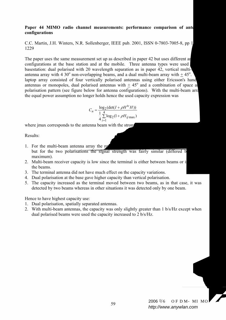
59
Paper 44 MIMO radio channel measurements: performance comparison of antenna configurations C.C. Martin, J.H. Winters, N.R. Sollenberger, IEEE pub. 2001, ISSN 0-7803-7005-8, pp 1225-1229 The paper uses the same measurement set up as described in paper 42 but uses different antenna configurations at the base station and at the mobile. Three antenna types were used at the basestation: dual polarised with 20 wavelength separation as in paper 42, vertical multi-beam antenna array with 4 30o non-overlapping beams, and a dual multi-beam array with + 45o. The laptop array consisted of four vertically polarised antennas using either Ericsson's handset antennas or monopoles, dual polarised antennas with + 45o and a combination of space and polarisation pattern (see figure below for antenna configurations). With the multi-beam array the equal power assumption no longer holds hence the used capacity expression was
∑=
+
+= 4
1max2
2
)1(log41
))(det(log
iij
tcn
H
HHICρ
ρ
where jmax corresponds to the antenna beam with the strongest received signal. Results: 1. For the multi-beam antenna array the received power varied considerably between beams
but for the two polarisations the signal strength was fairly similar (differed by 4 dB maximum).
2. Multi-beam receiver capacity is low since the terminal is either between beams or in one of the beams.
3. The terminal antenna did not have much effect on the capacity variations. 4. Dual polarisation at the base gave higher capacity than vertical polarisation. 5. The capacity increased as the terminal moved between two beams, as in that case, it was
detected by two beams whereas in other situations it was detected only by one beam. Hence to have highest capacity use: 1. Dual polarisation, spatially separated antennas. 2. With multi-beam antennas, the capacity was only slightly greater than 1 b/s/Hz except when
dual polarised beams were used the capacity increased to 2 b/s/Hz.
2006 年6月OFDM-MIMO专题 http://www.anywlan.com
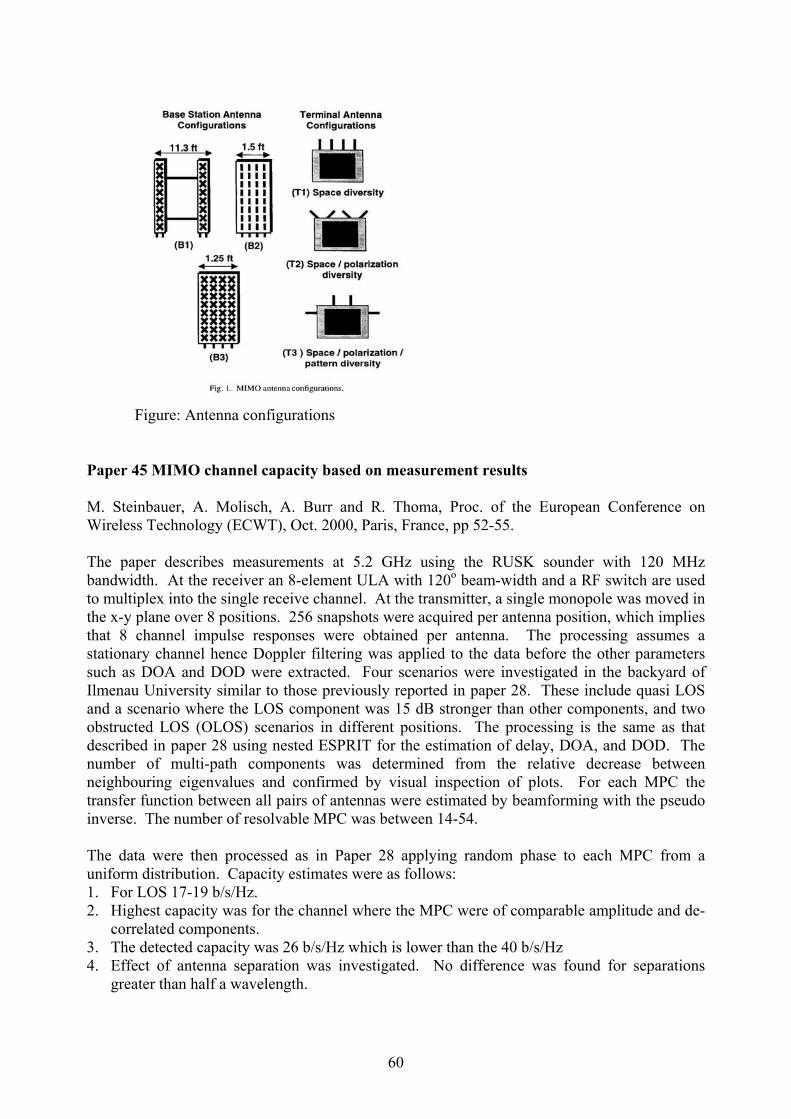
60
Figure: Antenna configurations
Paper 45 MIMO channel capacity based on measurement results M. Steinbauer, A. Molisch, A. Burr and R. Thoma, Proc. of the European Conference on Wireless Technology (ECWT), Oct. 2000, Paris, France, pp 52-55. The paper describes measurements at 5.2 GHz using the RUSK sounder with 120 MHz bandwidth. At the receiver an 8-element ULA with 120o beam-width and a RF switch are used to multiplex into the single receive channel. At the transmitter, a single monopole was moved in the x-y plane over 8 positions. 256 snapshots were acquired per antenna position, which implies that 8 channel impulse responses were obtained per antenna. The processing assumes a stationary channel hence Doppler filtering was applied to the data before the other parameters such as DOA and DOD were extracted. Four scenarios were investigated in the backyard of Ilmenau University similar to those previously reported in paper 28. These include quasi LOS and a scenario where the LOS component was 15 dB stronger than other components, and two obstructed LOS (OLOS) scenarios in different positions. The processing is the same as that described in paper 28 using nested ESPRIT for the estimation of delay, DOA, and DOD. The number of multi-path components was determined from the relative decrease between neighbouring eigenvalues and confirmed by visual inspection of plots. For each MPC the transfer function between all pairs of antennas were estimated by beamforming with the pseudo inverse. The number of resolvable MPC was between 14-54. The data were then processed as in Paper 28 applying random phase to each MPC from a uniform distribution. Capacity estimates were as follows: 1. For LOS 17-19 b/s/Hz. 2. Highest capacity was for the channel where the MPC were of comparable amplitude and de-
correlated components. 3. The detected capacity was 26 b/s/Hz which is lower than the 40 b/s/Hz 4. Effect of antenna separation was investigated. No difference was found for separations
greater than half a wavelength.
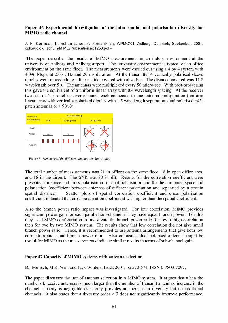
61
Paper 46 Experimental investigation of the joint spatial and polarisation diversity for MIMO radio channel J. P. Kermoal, L. Schumacher, F. Frederiksen, WPMC´01, Aalborg, Denmark, September, 2001, cpk.auc.dk/~schum/MIMO/Publications/p1258.pdf - The paper describes the results of MIMO measurements in an indoor environment at the university of Aalborg and Aalborg airport. The university environment is typical of an office environment on the same floor. The measurements were carried out using a 4 by 4 system with 4.096 Mcps, at 2.05 GHz and 20 ms duration. At the transmitter 4 vertically polarised sleeve dipoles were moved along a linear slide covered with absorber. The distance covered was 11.8 wavelength over 5 s. The antennas were multiplexed every 50 micro-sec. With post-processing this gave the equivalent of a uniform linear array with 0.4 wavelength spacing. At the receiver two sets of 4 parallel receiver channels each connected to one antenna configuration (uniform linear array with vertically polarised dipoles with 1.5 wavelength separation, dual polarised +45o patch antennas or + 90o/0o.
3�
-45
3�
-45
+45
3�
Novi2
Nokia
Airport
MS BS (dipole) BS (patch)
Measuredenvironment
����
Antenna set-up
-45
Figure 3: Summary of the different antenna configurations.
The total number of measurements was 21 in offices on the same floor, 18 in open office area, and 16 in the airport. The SNR was 30-31 dB. Results for the correlation coefficient were presented for space and cross polarisation for dual polarisation and for the combined space and polarisation (coefficient between antennas of different polarisation and separated by a certain spatial distance). Scatter plots of spatial correlation coefficient and cross polarisation coefficient indicated that cross polarisation coefficient was higher than the spatial coefficient. Also the branch power ratio impact was investigated. For low correlation, MIMO provides significant power gain for each parallel sub-channel if they have equal branch power. For this they used SIMO configuration to investigate the branch power ratio for low to high correlation then for two by two MIMO system. The results show that low correlation did not give small branch power ratio. Hence, it is recommended to use antenna arrangements that give both low correlation and equal branch power ratio. Also collocated dual polarised antennas might be useful for MIMO as the measurements indicate similar results in terms of sub-channel gain. Paper 47 Capacity of MIMO systems with antenna selection B. Molisch, M.Z. Win, and Jack Winters, IEEE 2001, pp 570-574, ISSN 0-7803-7097, The paper discusses the use of antenna selection in a MIMO system. It argues that when the number of, receive antennas is much larger than the number of transmit antennas, increase in the channel capacity is negligible as it only provides an increase in diversity but no additional channels. It also states that a diversity order > 3 does not significantly improve performance.

62
Instead of using MRC the paper suggests the use of selection diversity, which also results in a reduction in the number of RF channels. In MIMO context this will be referred to as hybrid selection/MIMO. This is useful for low rank matrices. Assumptions: 1. Transmitter uses all antennas. 2. Receiver H-S MIMO. 3. Flat fading, quasi-stationary and iid. 4. Uniform power/no water-filling. 5. Generate a sub-channel matrix by striking out the unused columns. This is achieved by first
estimating the full channel matrix, which can be obtained by multiplexing the receive antennas during the training period. Hence we need to add a few more training bits which results in a slight reduction of data.
Under above assumptions the upper bound on channel capacity is given by:
∑=
+=tn
iiC
12 ))(1(log ργ
where nt is the number of transmit antennas, γ(i) Chi- square distribution with 2L DOF, and L is the number of selected antennas. Monte Carlo simulations with iid channels and CDF's for 3 by 8 antennas and various values of selected antennas (< 3, 3, 8) were computed for 20 dB SNR and 10% outage capacity. Capacities were found to decrease drastically for < 3 receive antennas, 18.2 b/s/Hz for 3 antennas and 21.8 b/s/Hz for 8 receive antennas. Note the upper bound for full capacity (all 8 antennas used) was only equal 24.4 b/s/Hz in comparison to 20.1 b/s/Hz for 3 receive out of 8. Also the influence of SNR was investigated. For low SNR, the increase in signal level has more effect than at high SNR. The selection criterion on the basis of capacity instead of SNR was also investigated. The two methods chose the same channels for only 50% of the cases. This effect was explained in terms of the phase shift between antenna elements. For the SNR criterion the capacity reduces from 18 to 14.3 b/s/Hz at 20 dB SNR. Paper 48 On optimum MIMO with antenna selection R. Blum and J. Winters, IEEE Communications Letters, vol. 6, No. 8, August 2002, pp 322-324 The paper proposes the same as in paper 47 but in this case it suggests selection at both the transmitter and receiver where there is feedback to the transmitter to inform it of the selected antennas. In this case the Ergodic capacity is given by
{ } ( )( ){ }tcnr QHHIECE 112 detlog +=
H1 is selected channel matrix, chosen to maximise capacity, Q is for a single data stream, constant matrix with all entries equal to ρ/nt which can sometimes give a better performance than Q=ρ/nt Int.
63
Paper 49 On the capacity of cellular systems with MIMO R. Blum, J. Winters, and N.R. Sollenberger, IEEE Communications Letters, vol. 6, No. 6, June 2002, pp 242-244. The paper proposes adaptive MIMO for cellular systems since co-channel interference can seriously degrade overall capacity. The paper concludes that the largest mutual information (MI) is achieved when the number of data streams is controlled depending on the co-channel interference i.e. adaptive number of streams is transmitted. Sometimes, transmitting fewer data streams can increase the capacity. Paper 50 Spatial characterisation of indoor radio channel measurements at 5 GHz R. Stridh and B. Ottersten, 1st IEEE Sensor Array and Multichannel Signal Processing Wokshop. The paper investigates channel capacity for WLAN at 5.8 GHz. WLAN can be used indoor or outdoor in hot spots-on campus or at airports. The capacity is investigated for: 1. Uniform power distribution 2. Non-uniform power distribution (water-filling)
Y(t) = W*r HWt s(t)+ W*
r n(t) where the weights are used at both the transmitter and receiver. H=USV* (SVD) then if the weights are chosen as: Wt = Vγ (γ are the waterfilling weights), and Wr = U
∑=
+=n
ii
ti n
C1
22 )1(log σρε
the σ’s are the singular values of H and the εi’s are the optimum values for waterfilling. Measurements were performed at night by placing the transmitter in the office and the receiver in an open area resulting in NLOS measurements with 10-15 m distance between transmitter and receiver. A PRBS sounder with 400 MHz bandwidth at 5.8 GHz was used for the measurements. Single monopoles forming synthetic antenna arrays were used. 7 transmit positions separated by 300 mm and 21 positions separated by 1/4 wavelength (5 λ) with 20 samples at each position were measured. The channel matrix was normalised with 100 frequencies chosen at 5.8 GHz + 0.13 GHz. The results of simulations assuming iid channel matrix, transmit antennas 1,2,3 and receive antennas 3 were: 1. As nr > nt C increased logarithmly i.e. due to an increase in SNR from noise averaging. 2. An increase in antenna spacing more than a wavelength did not affect C. When
measurements were compared with simulations, d=2λ produced a channel closer to iid.
64
3. Waterfilling gives higher capacity for nr < nt=3. For nr > nt, the gain is smaller for uniform power allocation.
Note: antenna separation at transmitter is 6λ. Paper 51 MIMO channel capacity on a measured indoor radio channel at 5.8 GHz R. Stridh, P. Karlsson and B. Ottersten, Proc. of Asilomar Conference on Signals, Systems and Computers, 2000. Same measurement set-up as previous paper but the paper discusses the wideband channel. For a 20 MHz bandwidth for HiperLAN/2 it is shown that more than 80% of the channels reach 300 Mbit/s at 20 dB SNR. Paper 52 High data rate indoor wireless communications using antenna array M. Gans, R. Valenzuela, J. Winters, and M. Carloni, IEEE, 1995, pp 1040-1046. ISSN 0-7803-3002 The feasibility of using highly directive antennas at the transmitter and receiver to reduce delay spread is investigated. Ray tracing prediction and measurements show that, using antennas with 15o beamwidth at both ends, can provide high speed ubiquitous communication. Using antenna arrays with 50 to 200 elements at both ends, a 1Gbps can be achieved. Paper 53 Effect of fading correlation on adaptive arrays in digital mobile radio J. Salz and Jack Winters, IEEE Transaction on Vehicular Technology, vol. 43, No. 4, Nov. 1994, pp 1049-1057. The paper discusses the effect of correlation on the performance of adaptive arrays with optimum combining which minimises the mean square error (MMSE). Two channel models were examined: flat fading and two path model (a+b exp(-jωτ)) where a and b are independent complex Gaussian random variables. Note the coefficients at the different antennas are not necessarily independent due to the limited beamwidth of angular spread of multipath. In this case a uniform angular spread is assumed within a particular cone. The correlation was computed for different antenna spacing and angular spreads. The effect on interference nulling was found both theoretically and by simulations. The results show that for M antennas M-1 interferers can be nulled independent of the fading correlation. The only parameter that changes with correlation is the required spatial separation of the interfering signals: without fading the signals must be separated by the antenna beamwidth while with fading the signals (for 180o angular spread) need only be separated by half a wavelength. Note that increasing the spacing between antenna elements more than λ/2 decreases the beamwidth and introduces grating lobes (antenna pattern repeats every 90/(D/λ)). With increasing correlation the paper concludes that the array effectiveness to suppress interference is not affected but its effectiveness against fading is reduced. The degradation is small even for 0.5 correlation for antenna spacing of 4λ and 20o beam-width. This beamwidth can be reduced

65
even further by larger antenna spacing since this beamwidth is inversely proportional to the antenna spacing. Paper 54 The impact of antenna diversity on the capacity of wireless communication systems J. Winters, J. Salz, and R. G. Gitlin, IEEE Transactions on Communications, vol. 42, No. 2/3/4 Feb./Mar/April, 1994, pp 1740-1751. The paper discusses the advantages of using multiple antennas for interference suppression. Interference can be from users in the same cell or from neighbouring cells. Cancelling interference hence allows more users in the same cell and/or increase frequency reuse distance between cells thus eliminating the need for micro-cells which require more base stations and more handoffs. Expressions for bit error rate using zero-forcing optimum combiner solution for flat Rayleigh fading and frequency selective fading including a simple two-ray model are derived. For the flat Rayleigh case the result for each user is the same as for MRC with M-N+1 when the number of antennas is M, and the number of interferers is N. For the two ray model Monte Carlo simulations were carried out for different ratios between the delay between the two paths and the symbol period. For all values of M, the bit error rate decreases with the ratio until the delay is equal to the symbol duration i.e. when the bandwidth of the signal is equal to the bandwidth of the channel. The results for flat fading are seen to hold for frequency selective fading with equalisation. The analysis was applied to the digital TDMA system IS-54 and applications to CDMA, and GSM were discussed. Paper 55 On capacity of MIMO systems in correlated channels M. Ivrlac, T. Kurpjuhn, C.Brunner, and J.Nossek , In ITG-Fokusprojekt Mobilkommunikation 'Systeme mit intelligenten Antennen', Ilmenau, Germany, 2001, http://www.nws.ei.tum.de/cgi-bin/nws/publications?LANG=de&WER=miiv The paper discusses the different expressions for MIMO capacity with channel knowledge i.e. reciprocal channels where the transmitter has instantaneous knowledge of the channel matrix (Singular value decomposition where the channel capacity is expressed in terms of the eigen values), semi-reciprocal channels where the transmitter has knowledge of the long term average value of the channel matrix, non-reciprocal channels where the transmitter has no knowledge of the channel matrix. An expression for the independent-path channel where there are L-paths connecting the transmitter and receiver resulting in the row elements being correlated but the rows are pairwise independent The corresponding channel matrix is
T
trGA
AANH T=
2006 年6月OFDM-MIMO专题 http://www.anywlan.com
66
where A is N by L matrix of L array steering vectors of transmit array, G is the M by L matrix with uncorrelated elements and drawn from a complex Gaussian zero mean and unity variance distribution. N, M are the numbers of transmit and receive antennas respectively. This also corresponds to the situation when the receiver is surrounded by local scatterers. Simulations for 8 by 8 MIMO systems for uncorrelated semi-reciprocal Gaussian channel with the capacity of a correlated L-path semi-reciprocal channel with L=1,2,3 uncorrelated paths were performed. The results show that as the number of paths increases the capacity increases but that the uncorrelated channel outperforms the correlated channel for high-transmitted power. Paper 56 Influence of environment on capacity of LOS city street MIMO channel N. Tarhuni and T. O. Korhonen, http://www.hut.fi/Units/Radio/URSI02/ursi_tarhuni.pdf, The paper presents results of simulations of MIMO capacity in street canyon using to a deterministic channel model, which takes into account the width of the street, the wall permittivity and the reflection order. The simulations were performed for linear vertical antenna arrays with 4 × 1 to 4 × 4 antenna configurations as well as the single input single output channel. The simulations assume the following parameters: antenna spacing of half a wavelength at both ends, mobile station antenna height of 1.8 m, basestation antenna height is 15 m and it is located at a distance of a quarter of the street width from the wall while the mobile station is moved from 100 to 120 m from the base station in steps of 0.01 meter. The simulation frequency was 2.154 GHz and the signal to noise ratio was assumed to be 20 dB. The results show that for a four by four setup, when the street width is 40 m and the wall permittivity is equal to 15 the mean capacity is about 19 b/s/Hz. As the street width is increased the capacity approaches that of free space and the capacity gain is due to the antenna diversity. For walls with higher permittivity the capacity also increases since the reflected components have comparable power to the LOS component. Also the mean capacity increases for reflection order up to five. The simulations do not take the street crossings into account and assume the street walls to be flat smooth surfaces. Paper 57 Narrowband MIMO channel modelling for LOS indoor scenarios K.Yu DM. Bengtsson, B. Ottersten and M. Beach, URSI 27th General Assembly, Maastricht, 2001August 17-24, 2002, paper 0162 The paper presents a model for indoor LOS environments based on measurements at 5.2 GHz using the MEDAV sounder at the University of Bristol with 8 by 8 antenna arrays where the elements were separated by λ/2 and the transmit antennas were omni-directional and the receive antennas had a beamwidth of 120°. Each measurement took 5.3 sec and people were moving around. The measurements were used to extract the Rayleigh fading components from the composite signal, which contained a LOS component. In this way the channel matrix was divided into two components: the deterministic component and the Rayleigh component. Note that the deterministic component was not only made up of the direct path but also faded due to reflectors from ceilings, floors and sidewalls.

67
The data from the NLOS locations were averaged in time and in space to extract the channel function whereas the LOS locations were not averaged. The model for the Rayleigh part is the same as that given in paper 4 by Da-Shan Shiu et.al the dominant part is given by
TDD ga )(θ
which is related to the dominant direction of arrival, Dθ and the complex gain factor of the channel T
Dg . This work is part of the SATURN project Paper 58 An experimental broadband 4 by 4 MIMO test-bed B. Vandeweile and P.Mattheijssen, URSI 27th General Assembly, Maastricht, 2001August 17-24, 2002, paper 1134 The paper describes hardware architecture for measuring the performance of wideband MIMO systems in the 5.8 GHz ISM band, with 20 MHz bandwidth. The transmitter sends four independent data sequences with zero mean and mapped onto (M-ary QAM). A training sequence is included to form a frame At the receiver the best sampling time is identified with training sequences known at the receiver. The test-bed was used in the indoor environment and frequency transfer functions for 2 by 2 system are given with the corresponding impulse response. The antennas used in the measurements were patch antennas with directivity properties only in a half plane. The transmitter is mounted on a x-y scanner and the measurements were taken at night in a quiet environment. Paper 59 Broadband measurement analysis of indoor space-time channels G.Dolmans M.Colllados, URSI 27th General Assembly, Maastricht, 2001August 17-24, 2002, paper 1139 The paper gives results of measurements obtained with the test bed described in paper 58. The results are presented for delay spread, amplitude and phase density functions and correlation coefficient between the array elements at the transmitter and at the receiver using the Kronecker product of the correlation matrices. The results show that for 99% of the cases the rms delay spread is below 59 nanoseconds. The amplitude distribution was found to be Rayleigh distributed and the phase to be uniformly distributed. For a two by two MIMO system the correlation coefficient appears to be below 0.4 for antenna separation of one wavelength at both the transmitter and at the receiver. Paper 60 Experimental investigation of multipath richness for multi-element transmit and receive antenna arrays J.P.Kermoal, P.E.Mogensen S.H.Jensen,J.B.Anderson, F.Frederiksen, T.B. Sorensen and K.I.Pedersen, IEEE conference on vehicular technology, VTC 2000 Spring, Tokyo, Japan, May 2000, pp 2004-2008
2006 年6月OFDM-MIMO专题 http://www.anywlan.com

68
The paper presents results of measurements in a microcell scenario where the transmitter is placed outside the building and the receiver is placed inside a building at 300m away from the transmitter. The measurements were analysed to obtain the eigenvalues in both correlated and uncorrelated locations. The transmitter antenna was mounted on a rotating arm and the receiver antenna used four antennas with +45° and four antennas with -45°. The results for the correlated channel show that there is only one significant eigenvalue whereas for the uncorrelated scenario three eigenvalues with reasonable power were detected. For the correlated case the enhancement in channel capacity is due to the array gain i.e. 10 log M. For example for a 4 receive antenna element a 6 dB gain is obtained while for a 4 by 1 topology the gain is 9 dB where the diversity again is added to the antenna gain. These observations were confirmed by the measurements where the capacity for a correlated channel with 1 by 4 antenna configuration was 9.92 b/s/Hz and for a 4 by 1 configuration the capacity was 11.08 b/s/Hz. The capacity for the correlated channel was found to be 17 b/s/Hz and 27.9 b/s/Hz for the uncorrelated channel with a 30 dB SNR. The capacity was also found to increase with polarisation diversity. The eigenvalue decomposition method used in the analysis is only useful when the transmitter has knowledge of the channel and water-filling is applied. This can be available for TDD channels whereas for FDD channels it is necessary to feedback the channel parameters. Paper 61 Antenna arrays in mobile communications: gain, diversity, and channel capacity J. B. Andersen, IEEE Antennas and Propagation Magazine, vol. 42, No. 2, April 2000, pp 12-16 The paper discusses the use of antenna arrays at the transmitter and at the receiver from the point of view of gain and diversity using transmitter and receiver weights. It distinguishes four possible scenarios with regard to angular spread being high or low at the transmit and receive ends. The beam mode for both arrays arises when the weight vector is one giving a gain of either M or N for low angular spread at either end, MN, or 1 for low angular spread at both ends or high angular spread at both ends respectively. For maximum gain combining three cases give MN gain while the case of high angular spread at
both ends gives a gain of ( )2NM ÷ . The diversity order for these four scenarios are one for
low angular spread at both ends, N or M for high and low angular spread, and MN for high angular spread at both ends. When the singular value decomposition is applied at both ends the gain factors become equal to
the eigenvalues, which are limited by ( )2NM ÷ . This is useful when there is high angular
spread at both ends. The decomposition is equivalent to setting up separate channels since the weight vectors are orthogonal.
For large array sizes the eigenvalues are bounded by ( )2NM − and ( )2
NM ÷ .
69
Paper 62 Capacity of MIMO systems in realistic cellular wireless systems A.G. Burr, IEE conference publication 02/112, ‘Getting the most out of the radio spectrum’, 24-25 October 2002, 26/1-26/5 The paper discusses three main effects on MIMO systems: finite number of scatterers the effect of interference, and adaptive MIMO. The effect of scatterers is quantified by a new expression for the channel capacity in which the eigenvalues are replaced by the multipath gains and the
limits on the sum are replaced by the number of multipath components, i.e. 2ir
t
i nn
ξλ
=
Monte Carlo simulation was used to calculate channel capacity versus the number of transmit and receive antennas where the number of scatterers was assumed to be eight and the arrays were both ULA with half a wavelength spacing. The single bounce model was assumed. The effect of interference is analysed with the assumption that the other cell interference predominantly comes from a particular direction or a small number of directions. In this case the optimum receiver uses a pre-whitening filter to maximise the signal to noise ratio. This has the effect of reducing the degrees of freedom available to the wanted signal, and hence suppressing some of the eigenvalues potentially reducing capacity. The effects of adaptive MIMO systems are illustrated by simulations, with eight scatterers and water-filling. The capacity enhancement of adaptive MIMO is seen to increase with the number of antennas. The paper then comments about the reciprocity of the MIMO link i.e. uplink and downlink reciprocity. Paper 63 Digital wireless communications using MIMO links: applications to broadband mobile systems Overview by Professor David Gesbert, http//www.ifi.uio.no/¬gesbert/mimo_research.html MIMO applications are identified in the following environments:
• Indoor wireless LANs • Wireless local loop • Metropolitan voice/ data wireless networks (UMTS, EDGE, fourth generation networks) • Very high speed and mobile wireless ( point to multipoint) • Acoustic communications • Broadcast systems ( HDTV)
The overview highlights several of the open problems in MIMO research. These include channel modelling since the original MIMO concept was developed based on Rayleigh independent fading channels, MIMO capacity based on measurements of the propagation environments, signalling schemes and receiver design for MIMO systems, the development of a unifying scheme for spatial multiplexing and diversity schemes.
70
Additional problems of interest are MIMO algorithms coping with fast time varying channels due to user mobility, and interaction between MIMO based physical layer and medium access control. Paper 64 Smart antennas and spatial multiplexing D. Gesbert, http://www.ifi.uio.no/~gesbert/spatialmux_primer.htn Basic concepts of spatial multiplexing are outlined. The advantages of smart antennas are identified as: improvement in the signal to noise ratio through beam forming, reducing interference due to channel reuse, improving the link reliability through diversity techniques, mitigating the inter-symbol interference in multipath environments and increasing the throughput through creation of multiple parallel spatial channels (MIMO systems). Paper 65 An antenna solution for MIMO Channels: the switched parasitic antenna M. Wennstrrom and O. Svantesson, IEEE Symposium on Personal Indoor and Mobile Radio Communication (PIMRC) 2001, San Diego, USA, September 30- October 3 2001. http://www.signal.uu.se/Publications/pdf/c0114.pdf The paper proposes the use of a switched parasitic antenna at both the base station and user equipment for MIMO applications. The proposed antenna gives the advantage of reduced RF complexity in that it only requires one transceiver. Simulations are reported for different configurations including the use of arrays at both ends, parasitic elements at one end and an array of the other, and parasitic antennas at both ends. The results show a reduced channel capacity with the parasitic antenna however this reduction is not very high in comparison to the ideal i.i.d. matrix, for example the 90% CDF for the parasitic antenna at both ends is equal to 2.2 s/s/Hz in comparison to 2.55 b/s/Hz for the i.i.d. case (for 4 dB SNR) . Also the channel capacity at 10% outage was investigated as a function of the scattering radius. The results show that the channel capacity increases as the scattering of radius increases. Bit error rates for two space-time coding schemes were also investigated (Alamouti scheme and the orthogonal delay optimal rate codes for two, four, eight: Tarokh codes). The bit error rate results show that the array array configuration gives 5 dB better than the array switched parasitic area configuration. The assumptions for using the switched parasitic antenna are quasi-stationary environment and flat fading. Presentation 5 The MIMO channel capacity potential-how much as possible? Christian Schlegel, WPMC 2002, October 30, 2002, Hawaii, www.ee.ualberta.ca/hcdc This presentation was given as part of a panel session on MIMO. The presentation is an overview of various papers published by the author and others. It starts off by comparing the channel capacity of an orthogonal channel and the average capacity of a random eight by eight

71
MIMO channel. Also compared are the water filling capacity and the symmetric capacity. At about 17.8 dB SNR the difference in capacity is equal to 8.6 bits per channel use. The rapid variations with time of the channel coefficients is shown not to significantly vary the channel capacity where the effect of SNR is demonstrated to be more significant. The effect of low SNR is shown to be similar to a low rank channel matrix that is a single antenna channel. The information theoretic capacity of a random MIMO channel with equal number of transmit and receive antennas and for twice the number of receive antennas is compared for different types of receivers including the orthogonal, successive and MMSE with linear pre-processing. The results show that a small reduction results from the use of an MMSE architecture. Also different types of coding were compared including detective iterative turbo, iterative differential, and space-time Trellis. The linear pre filtering is speculated to gain most of the available capacity especially at low SNR. Paper 66 The diversity gain of transmit diversity in wireless systems with Rayleigh fading J. Winters, IEEE Transactions on Vehicular Technology, Vol. 47, No.1, Feb. 1998, pp 119-123 http://www.jackwinters.com/00661038.pdf The paper presents simulation results comparing diversity at the transmitter with receive diversity for multiple antennas. With transmit diversity the different antennas send delayed signals of the same symbol where the delay is chosen appropriately to cover the delay spread in the channel. The transmitted power is assumed to remain the same as for the single transmit antenna by dividing the total transited power equally between the antennas. The following assumptions were made:
• Transmitted symbols are independent • Flat finding • Independent fading from each transmit antenna to each receive antenna
The paper also briefly mentions the advantage of using transmit diversity in a multiple transmit multiple receive system. Paper 67 The range increase of adaptive versus phased arrays in mobile radio systems J. Winters and M. J. Gans, IEEE Transactions on vehicular technology vol. 48 No. 2 March 1999, pp 353-362 The paper compares the performance of adaptive arrays versus phased arrays with respect to range increase and the required number of elements to achieve the same performance. With the phased array the received signals are weighted and combined to create a beam in the direction of the mobile similar to a sectored antenna. As the number of antennas increases, the received signal gain (range) increases proportionally to the number of antennas but only until the beamwidth of the array is equal to that of the angle of multipath scattering around the mobile. Beyond that point the increased gain of more antennas is reduced by the loss of power from scatterers outside the beamwidth. The range can be even reduced with narrower beamwidths because the resulting reduction in delay spread can cause a loss of diversity gain in systems using equalization (RAKE receiver).
2006 年6月OFDM-MIMO专题 http://www.anywlan.com

72
With adaptive arrays the signal received by each antenna are weighted and combined to maximize the output SINR. Maximizing SINR also forms an antenna pattern matched to the wave front and therefore provides a range increase that is not limited by the scattering angle. Also adaptive arrays can provide diversity gain since all the receive antennas can be used for diversity combining. Thus for a given number of antennas adaptive arrays can provide greater range or require fewer elements to achieve a given range. For example the paper shows that for a 3° scattering angle a 100-element array base station can increase the range 2.8 and 5.5 fold with a phased array and an adaptive array respectively. Also for this angle the range increase of a 100-element phased array can be achieved by an adaptive array with only ten elements.
These results are supported by Monte Carlo simulation assuming twenty scatterers distributed uniformly in a circular area of radius r around the mobile and transmission from a mobile to a base station. The different antenna architectures including cylindrical and rectangular arrays are compared in terms of the required antenna spacing and coupling effects. Paper 68 On the capacity of radio communication systems with diversity in a Rayleigh fading environment Jack Winters, IEEE journal on selected areas in communications vol. SAC-5 June 1987, pp 871-878 The paper analyses two basic communication systems: 1) communication between multiple mobiles and a base station with multiple antennas, 2) communication between two mobiles each with multiple antennas. The information-theoretic capacity and the efficiency index (maximum data rate for a given error rate) in b/s/Hz are determined for different processing techniques. This is the first paper that discusses the use of multiple antennas at both ends of the radio link and gives the capacity expression in terms of the eigenvalues of the channel matrix. The assumptions were for independent flat Rayleigh fading between antennas and constrained total power per user. The paper concludes that M independent channels can be set up between M transmit and M receive antennas.
Paper 69 Experimental characterization of the MIMO wireless channel: data acquisition and analysis J.Wallace, M. Jensen, A. Swindlehurst, and B. Jeffs, IEEE Transaction on Wireless Communications, March 2003, http://goliath.ee.byu.edu/grad1/users/swindle/www_docs/pdffiles/wallace.pdf The paper describes a measurement system developed for MIMO channels. It consists of up to sixteen channels of binary shift keying in signal with 25 kHz bandwidth at 2.425 GHz. A sixteen channel data acquisition card with a 1.25 MHz sampling rate was used at the receiver. This gave an acquisition rate of 80 ms for each measurement. Various antenna arrays were used for the measurements, which were carried out indoors in one of the buildings of the university. The specific antenna arrays employed were four element single polarization patches with half wavelength spacing, two element dual polarization vertical and horizontal patches with half wavelength spacing, and ten element monopole with quarter wavelength spacing. Data records were ten seconds long.

73
The data are processed to determine the channel matrix elements statistics, channel temporal correlation, channel spatial correlation and channel capacity according to the water filling solution. The results show that the single polarization elements performance is inferior to the dual polarization case due to the substantial correlation between the elements. Using Monte Carlo simulation the capacities for both the dual polarized and the dual polarized elements with spacing were found to be virtually identical. The dual polarized elements give higher capacity than the i.i.d. matrix which can be attributed to the small coupling between the orthogonal polarizations giving a channel matrix which is nearly diagonal. The comparison indicates that for compact arrays of closely spaced elements, dual polarization is an attractive choice. However when wide separation is possible, spatially separated elements are more attractive due to the power advantage. Comparing the patch antennas with the monopoles the results show that the omni-directional antennas slightly outperform the more directive patch antennas. Note that for omnidirectional antennas the multipath richness is higher than for the directional antenna however this is offset by the gain of the directional antenna. The dependence on the number of elements was explored by using two, four, and ten monopole transmit and receive antennas. For all configurations the same total length of 2.25λ was used. The measurements show that as the number of antennas increases the capacity per antenna drops due to the higher correlation between adjacent elements. The effect of path loss was also examined and locations with low path loss exhibited higher capacity than locations, which suffered from high path loss.
Paper 70 Fundamental limits of MIMO capacity for spatially constrained arrays T.S. Pollock, T.D.Abhayapala, and R.A. Kennnedy, Austrialian Communication Theory Workshop Proceedings 2003 The paper discusses the effect of the volume containing the antenna elements at the transmitter and at the receiver. The channel model assumes a scatter free radius for the volume containing the transmitter and receiver antennas. This results in a channel matrix composed of the product of three distinct regions of signal propagation: transmitters, scatterers, and receiver. H=JR Ho J*T Both the transmit and receive matrices, J’s, describe the array geometry and are constant for fixed antenna locations within the spatial volume. For a random scattering environment the scattering channel matrix, Ho, would have random elements. The above decomposition indicates that the rank of the matrix H is the minimum of the rank of the three parts, which for the large number of antennas becomes the minimum of (2NT +1, 2NR +1), which refer to the size of the channel matrix and represent the number of modes. An expression for the maximum capacity is given for the case when the correlation between the antennas is zero where it is seen that the capacity increases linearly with the number of antennas. However if the rank of the antenna volume is smaller than the number of antennas then the capacity no longer grows with the antenna number and saturates at 2N+1. The capacity growth becomes zero at the saturation point. Therefore the maximum capacity for the region is defined by the capacity equation where the number of antennas in the equation is equal to the saturation number.
2006 年6月OFDM-MIMO专题 http://www.anywlan.com
74
Monte Carlo simulation were carried out to estimate the capacity for different array architectures including uniform circular array and uniform linear array where the saturation point is shown for a scattered volume of half a wavelength at the receiver and five wavelengths at the transmitter for a 10 dB SNR. The paper concludes that it is not possible to assign a spatial unit of capacity as with the traditional time and frequency concepts because doubling the region area or volume does not give a corresponding doubling of capacity. Paper 71 Predicting multi element receive and transmit array capacity outdoors with ray tracing J. Ling, D. Chizhik, R.Valenzuela, VTC 2001, http://www.bell-labs.com/org/wireless/wisepub/vtc2001_jonling.pdf The paper discusses the effect of diffraction on capacity of multiple element arrays. It first gives the theoretical capacity for a dyad matrix, which has a rank one and an ideal matrix, which has an identity covariance matrix. It shows that single edge diffraction results in a dyad matrix. If additional scatterers that bypass the wedge are present the entries in H will become a sum of dyads and the rank of the matrix increases. Ray tracing with two elements at the transmitter and two elements at the receiver was performed using a program developed at Bell labs for SNR= 20 dB for three cases one free space propagation; two single edge diffraction and three two wedges with single diffraction. The results show that at large distances the capacity drops for all three scenarios however for the two wedge situation the capacity oscillates rapidly at short distances and then decreases below that of free space. The lowest capacity is obtained with the single edge. For the free space case the capacity decreases as a function of distance as the antennas become less discernible. Paper 72 Simulating polarization diversity and power allocation in MIMO channels L. Schumacher, J.P. Kermoal, K.I. Pedersen, P.E. Mogensen, EPMCC, Vienna 20-22 February 2001 The paper presents results of Monte Carlo simulations using the COSSAP software. The simulated set-up consisted of a two by four MIMO channel in an outdoor to indoor microcenter scenario. The mobile station is assumed to have two antennas vertically polarized and with half a wavelength separation. At the base station four antennas are used in two configurations one half wavelength separation between elements and + 45° and in the second configuration two pairs of two antennas separated by half wavelength and with polarization of +45 °. Also simulated was the ideal uncorrelated channel, and the correlated channels. The simulations included the effect of correlation between the antenna elements at both the transmitter and at the receiver. These correlation values were taken from the ACTS project on smart antennas. The results show that the effect of correlation is to reduce the number of available eigenvalues hence the cross-polarized antennas gave better results than the copolarised antennas. Also the power allocation at the transmitter was investigated using both uniform power allocation and water filling. The latter approach is seen to provide some advantage in highly correlated

75
environments. So the paper concludes that the simulations confirmed previous experimental results obtained by B. Anderson.
Paper 73 Rapid prototyping design of a 4 by 4 BLAST over UMTS system M. Guillaud S. Das, A. Burg, M. Rupp, E. Beck, Proceedings of the 35th Asilomar Conference on Signals,Systems and Computers, Pacific Grove, CA, USA, November 4-7, 2001. http://www.eurecom.fr/~guillaud/publications/blast6.pdf A MIMO set up was implemented using gate arrays and DSP. The system was entirely designed using C code embedded in SIMULINK functions for simulation and after validation automatically mapped onto hardware platform. The paper describes the implemented architecture, the charnel model, the RAKE receiver and the finger assignment; the MIMO decoding algorithm and the simulation and implementation platforms. Paper 74 METRA: Experimental investigation of MIMO radio channels for indoor picocell scenarios J. P. Kermoal, L. S. Schuacher, P.E. Mogensen, and K. I. Pedesen, F. Frederiksen
Proceedings of IST Mobile Summit 2000, October, 2000, pp. 509-514, Galway, Ireland http://www.ist-metra.org/papers/Summit2000_4_Kermoal.pdf The results of indoor MIMO measurements with 4 by 4 elements are described. The transmitter switches between the antenna elements every 50 µs and the receiver uses parallel transmission. The sounding measurement was performed every 20 ms at a carrier of 2.05 GHz and a chip rate of 4.096 Mcps. The complex narrowband information was extracted from the wideband channel data. The height of the antenna arrays at the MS and the BS were 1.69 m and 2.34 m, respectively. The measurements were taken during quiet times to investigate time stationary picocell environments. At the MS the antenna array was moved using a slider over a distance of 9 wavelengths. Vertical polarized sleeve dipoles with average return loss of 14 dB and a cross-polar discriminator of 20 dB were used during the measurement. Simulations using were used to evaluate the mutual coupling between antenna elements. The effect of coupling is to change the radiation pattern resulting in 10 dB reduction in received signal from certain directions. Correlation measurements of MIMO channels require the use of omni-directional antenna elements. The measurements were also used to estimate DOA at the MS using a 0.4 wavelength separation between elements and an interleaved solution to resolve the forward/backward ambiguity. At the BS a ULA with 4 elements and a spacing of l.5 wavelength was employed since no DOA was planned at the Bs. Three indoor scenarios were investigated. The first referred to as Novi2 is an example of a building with several small offices on the same floor. The second called Nokia represents a typical modern open office environment. The last environment Novi.3 is a reception Hall. LOS and NLOS locations were measured.
2006 年6月OFDM-MIMO专题 http://www.anywlan.com
76
The measurements were analysed to extract the spatial correlation coefficient at the MS since the antenna separation at the BS was considered to be sufficiently large to assume lack of correlation. Definition of used correlation function is given. CDF’s of power correlation were computed for 21 locations for Novi2, 12 for Novi3 and 15 for Nokia. The results showed that for 90% of the locations the correlation was less than 0.6. The spatial power correlation matrices from the BS and the MS and the Doppler spectrum were fed into the COSSAP MIMO model for simulation. The measured and simulated results for the eigenvalues were also presented. The results show that four distinct eigenvalues are available in this 4 by 4 scenario and that an antenna separation of 0.4 wavelengths is sufficient to obtain decorrelation between elements. The results also show that the data and the simulations have Rayleigh distribution. The paper concludes that the statistical model is validated by the measurements. Paper 75 Experimental investigation of correlation properties of MIMO radio channels for indoor picocell scenarios J. P. Kermoal, L. S. Schuacher, P.E. Mogensen, and K. I. Pedesen, Proceedings of VTC 2000 Fall, September, 2000, Vol. 1, pp. 14-21, Boston, USA The paper presents the same measurement system and measurement results of those presented in paper 74. However it contains additional information with regard to the antenna radiation pattern and layout of measurement environment for two of the office types: the small office and the large open modern office. Paper 76 A stochastic MIMO radio channel model with experimental validation J. P. Kermoal, L. Schuacher, K. I. Pedesen, P. E. Mogensen and F. Frederiksen, IEEE Journal on Selected Areas in Communications, Vol. 20, No. 6, August 2002, pp 1211-1226. The paper proposes a statistical model for MIMO systems, which uses two correlation matrices at both ends of the transmission link and the associated Doppler spectrum of the channel paths. These parameters can be extracted from single input multiple output results. The following assumptions are made in the analysis: the complex transmission coefficients are assumed to be complex Gaussian distributed with identical average power, all the antenna elements in the two arrays have the same polarization and the same radiation pattern, and the correlation coefficient between each transmit and each receive antenna is given by the product of the correlation coefficient at the transmit side and the correlation coefficient at the receive side ( that is the correlation coefficients at both ends are independent). This implies that the spatial correlation matrix of the MIMO radio channel is the product of the spatial correlation matrix at the mobile station and the base station. The correlated channel coefficients are shown to be extracted from zero mean complex independent identically distributed random variables shaped by the desired Doppler spectrum provided that the correlation matrix is none singular. Therefore the model cannot take into account the keyhole effect. Two measurement set-ups were used to obtain results to validate the model. The first set-up used a synthetic circular antenna array with a separation of 0.5 wavelength between elements and the operating frequency was 1.71 GHz and the receiver had a uniform linear array with four elements spaced by 0.45 wavelengths polarized at + 45 degree. The second set up used interleaved antenna array with vertical polarization and the transmitter used a one to four switch between elements. The operating frequency was 2.05 GHz. The measurements were carried out with the system transmitting a
77
127 chip clocked at 4.096 Mcps giving a sounding time window of 14.6 µs with a sampling resolution of 122 ns. The narrow band information is subsequently extracted from the complex impulse response. The measurement environments included picocell and microcell scenarios at two locations one at the university campus and the other at the international airport. The stochastic model relies on the wide sense stationary assumption. The proposed model was validated using Monte Carlo simulation to compute the eigenvalues, which were then compared with the results of the measurements. Picocell uncorrelated results show that 17b/s/Hz can be achieved with a 4X4 MIMO set-up and that the difference between the two power allocation schemes (water-filling and equal power distribution) is very small. This is expected since the channel is uncorrelated. The effect of the antenna set-up and SNR was also investigated where an increase in SNR is seen to increase capacity. At low SNR the contribution of the strongest sub-channel is predominant. The results in general indicate that at low SNR the MIMO concept only provides a combined transmitter and receiver diversity and at high SNR the MIMO systems offer parallel channelling. The cell type was also discussed i.e. picocell versus microcell where the picocell is seen to offer fairly constant capacity in comparison to the micro-cell. The paper also includes an appendix, which contains the equations for the derived model. Paper 77 Channel characterization and modelling for the next generation MIMO wireless communication M. Jensen, J. W. Wallace and A. L. Swindlehurst, Fifth Wireless World Research Forum meeting Digest, http://www.Wireless-world-research.org, Tempe, AZ Mar 7-8 2002. (IST), Jensen-Byu-wwrf2002 The paper highlights a number of issues that still needs to be addressed in MIMO studies. These include the wideband response of the channel for broadband communications (10’s to 100’s of megahertz) and for frequency division duplex systems; polarization potential of the channel such as using the various degrees of communication freedom ( 3 electric and 3 magnetic polarization); multipath richness versus SNR and the use of space time coding algorithms that exploit MIMO architecture; intrinsic capacity of the channel which does not include the antenna effects; efficient channel model and evaluation of system architectures for achieving capacity including modulation schemes such as OFDM and CDMA. The paper also describes the measurement system used by the authors to characterize the narrow band MIMO channel at 2.425 GHz using sixteen transmit and sixteen receive antenna elements. The sounder was used in various indoor environments to obtain measurements with a dual polarization antenna configuration. The data were subsequently analysed to obtain the statistics of the achievable capacity as well as the pair wise joint statistics of the channel transfer matrix elements. Modelling using the modified Saleh-Valenzuela model (adding the angular spread to the model) was shown to give good agreement with the measured data. The authors also indicate that currently they are developing a wide band channel sounder as well as a 25 MHz real time MIMO communication test platform where the wide band sounder is expected to cover several hundred megahertz.
2006 年6月OFDM-MIMO专题 http://www.anywlan.com
78
Paper 78 Models for MIMO propagation channels, a review K. Yu and B. Ottersten Wiley Journal on Wireless Communications and Mobile Computing Special issue on adaptive antennas of MIMO systems, 8-7-2000 The paper proposes several classification methods of MIMO channel models. These include wideband models versus narrow band models, field measurements (from MIMO channel measurements) versus scatterers models (usually involves distributed scatterers), and physical versus none physical models. The non-physical models are based on the channel statistical characteristics using non-physical parameters. They are usually easy to simulate and provide accurate channel characterization. However, they do not give insight into the propagation characteristics of the MIMO channels and depend on the measurement equipment for example the bandwidth, the configuration and aperture of the arrays, and the heights and response of the transmit and receive antennas in the measurements. In contrast the physical models choose some crucial physical parameter to describe the MIMO propagation channel. Some typical parameters include angle of arrival, angle of departure, and time of arrival. However it is difficult to characterize the MIMO channel by a small number of parameters. In addition the measurement equipment (antenna responses, configuration etc.) affect the estimation of the parameter. Three non-physical models are discussed: the IST METRA project, the IST SATURN project narrow band and wideband models. The IST METRA model is a wide band MIMO model where the complex valued coefficients are assumed to be zero mean complex Gaussian and have the same average power, and the coefficients are independent from one time delay to another. The model takes into account the correlation between different pairs of complex transmission coefficients where both the spatial correlation coefficient at the transmitter and at the receiver are considered in the model. The model gives the power correlation matrix of the MIMO channel as the Kronecker product of the power correlation matrices seen from the transmitter and the receiver. One drawback of the proposed model is that the phase relationship between transmission coefficients is lost since the power correlation coefficients do not take the phase information into account. The IST SATURN narrow band model is based on measurements carried out in an indoor environment for none line of sight situation. The model proposes that the MIMO covariant matrix is the Kronecker product of the covariance matrices at the transmit and receive side respectively. In this model the channel covariance matrix is used instead of the power correlation matrix therefore providing the phase information of the MIMO channel. The structure was also discussed in the three GPP meeting. Assuming that the channel coefficients are zero mean complex Gaussian the first and second order moments of the MIMO channel are enough to characterize the propagation channel. This gives the channel matrix as the product of the square root of the transmit and receive covariance matrices and an i.i.d. matrix. This model was previously proposed by other researchers e.g. Gesbert et.al. (paper 29). The wide band model is an extension of the narrow band where in this case each tap of the MIMO channel response is the matrix with i.i.d. zero mean complex Gaussian elements. The authors propose that the elements of the i.i.d. matrix of this model can be presented by different SISO models. The physical MIMO models included seven different models. The first is the single ring and two ring models. In the single ring model the base station is assumed to be elevated and therefore not affected by local scattering while the mobile station is surrounded by scatteres. No
79
line of sight is assumed between the base station and the mobile station. In the two ring model both the base station and the mobile station are surrounded by scatters which can be the case for indoor wireless communications. The difficulty in this model is that the signals reflected by the scatterers at the transmit and receive sides are possibly not independent. Therefore the channel covariance matrix cannot completely describe the MIMO channel. The von Mises angular distribution model is a narrow band model similar to the single ring model but uses the probability density function of the angular spread at the mobile and takes the Doppler spread into account. This model was extended to include the LOS component. An important advantage of using the von Mises angular distribution is that it gives a closed form expression and therefore can be used to study the channel covariance analytically. The third physical model assumes distributed scattering at both the transmitter and receiver (paper 29). The fourth model is the extended Saleh-Valenzuela model, which proposes L clusters with K rays each. The rays in each cluster are assumed to be zero mean complex Gaussian and the cluster amplitude is Rayleigh distributed with a cluster decaying constant. The model was verified from narrowband indoor measurements where rich scattering was present. The COST 259 directional channel model takes into account the angle of arrival, the angle of departure and arrival time of the multipath components. In this model the propagation environment can be described by a number of external parameters such as frequency, height of base station and mobile station. To simulate the channel a layered approach was proposed were different environments have been separated into three levels. The top level is the cell type and each cell type includes a number of radio environments (second level) . For each environment some propagation scenario (third level) have been identified. The parameters in the second level are referred to as global parameters while those in the third level are called local parameters. The sixth model is the electromagnetic scattering model which takes the properties of the antennas as well as the channel into account. This model includes the antenna polarization properties through the antenna functions. It is a function of time and thus reflects the time variability of the MIMO channel therefore the Doppler shift is implicitly included in this model. The final model is the virtual channel model which assumes K scatterers within a cluster between the transmitter and the receiver and the MIMO channel for this case takes into account the path gain, the angle of arrival and the angle of departure for each scatterer in the cluster. Some indoor measurements are then used for both wideband and narrow band model evaluation. The paper proposes the following topics for future research: initial simulation carried out by the authors show that the Kronecker structure (IST SATURN narrowband model) gives high errors when both the base station and the mobile station have high covariances between neighbouring antenna elements. Other simulations show the need for the validation of the physical model from measurements to bridge the gap between the two groups of models. A validated physical model can greatly reduce the number of required measurements on designing MIMO communication systems and thus decrease the research and development costs. The second aspect, which needs to be verified is the inclusion of the line of sight component and the channel model since most models assume none LOS situation. In addition no outdoor MIMO channel models have been reported based on MIMO channel measurements. The outdoor scenarios are very different from the indoor scenarios where the Doppler shift is significantly higher for outdoor environments. Therefore to validate the proposed channel models it is important to carry out outdoor MIMO channel measurements.
80
Paper 79 Fundamental capacity of MIMO channels A. Goldsmith, S.A. Jafar, N. Jindal and S. Vishwanath, Department of Electrical Engineering, Stanford University, wsl.Stanford-edu/~ee359/mimo_tutorial.pdf This tutorial discusses the MIMO capacity of different types of channels including flat fading and frequency selective fading channels for the single user. Also the multiple access channel and the broadcast channel are briefly discussed. A substantial number of references are included. Paper 80 Improved Techniques for 4 Transmit and 4 Receive Antenna MIMO-OFDM for Wireless Communications R.S. Blum, Q.Yan, Y.Li and J.H.Winters, IEEE Transactions on Communications vol. 49 No. 11 Nov. 2001 pp 1873-1878 Paper 81 Signal Detection for MIMO-OFDM Wireless Communications Ye Li, J.H. Winters, and N. R. Sollenberger, IEEE Int. Conf. Common. June 2001 pp 3077-3081 Paper 82 Improved Space-Time Coding for MIMO-OFDM Wireless Communications R.S. Blum, Y.Li, J.H.Winters and Q.Yan, VTC01, ISSN 0-7803-6728-6/$10.00, 2001IEEE, pp 1298-1302 These three papers present results of simulation of a 4 by 4 MIMO system using OFDM modulation using either space-time coding across four antennas or across two antennas at a time. OFDM eliminates the need for equalization of wideband systems. The simulations are carried out for a bandwidth of 1.25 MHz, which is divided into 256 subchannels. The symbol duration is taken to be 204.8 µs so that the tones are orthogonal. The subchannel symbol rate is 4.44 kbaud. The effective transmitting rate is 4Mbit/s using 1.25 MHz of bandwidth so the transmission efficiency is 3.2 b/s/Hz. Different Doppler shifts up to 200 Hz were used in the simulations. Paper 83 Mutual coupling effects on the capacity of multielement antenna systems T. Svantesson, A. Ranheim, IEEE ICASSP 01, Salt Lake City, Utah, may 2001 The paper discusses the effects of mutual coupling between antenna elements of a MIMO system. It presents simulation assuming a dipole array, and a single scattering ring model for the study. The effect of mutual coupling in this scenario is shown to reduce the correlation between the elements and hence to improve the capacity. It is postulated that the coupling phenomenon actually decorrelates the signals by acting as an additional ‘channel’. For the case of localised scattering, the elements of the channel matrix will have a high degree of correlation regardless of whether coupling is included or not. Hence, there is no capacity gain in such scenarios. For the case of rich iid, coupling will degrade the performance. The

81
intermediate case, which is discussed in the paper shows that coupling can be beneficial and reduce the correlation between elements. Paper 84 Attainable throughput of an interference-limited multiple-input multiple-output (MIMO) cellular system S. Carteux, P.F. Driessen, and L.J. Greenstein, IEEE Transaction on Communications, Vol. 49, No. 8, August 2001, pp 1307-1311 The paper presents results of simulation of capacity for SISO, SIMO, and MIMO systems in a cellular environment where the first tier of six cells surround a cell in the centre. In this case one mobile user on a single frequency channel is assumed where all co-channel interferers are transmitting all the time. The simulation assumes the following:
1. Each user is randomly located with uniform probability over the cell. 2. Complex path gains to the serving and interfering bases by considering the inverse
distance law (3.7), Rayleigh fading (k-factor = 0 or 10), log normal shadow fading (standard deviation 0, 4, 8) and the antenna pattern when sectoring is used.
3. Processing either minimum mean square error (MMSE) or ordered successive interference cancellation OSIC-MMSE
4. Adaptive modulation rate where the number of modulation levels is varied according to the radio channel and interference conditions
5. The throughput per user is found by averaging over the short term Rayleigh fading of the path gains. The user’s spectral efficiency is a function of user position and shadow finding. Its average over all user locations and shadow fading is the mean spectral efficiency in b/s/Hz.
6. The total power transmitted on each link is the same and the SNR is the same at each receiver branch for a given location and is a random variable over the shadow fading.
7. Antennas at base station are either omni-directional or sectored with 90° beam width
Results: MIMO (3,3) suffers more performance degradation than SIMO (1,3) since the number of degrees of freedom for the SIMO system enables the cancellation of interference. For the case of, MIMO with more receive antennas than transmit antennas interference cancellation can be achieved and this also provides diversity gain against fading. The SIMO (1,6) gives a similar capacity to the MIMO (3,6). However, the mean spectral efficiency of 11 b/s/Hz implies a constellation with 2048 point for the SIMO system whereas the MIMO system only requires 16 constellation points (16 QAM). Comparing the uplink with the downlink indicated that in almost every case the uplink has higher capacity than the downlink by 10% to 24%. In the multi-cell environment there is a SNR beyond which the mean spectral efficiency becomes interference limited. This plateau is reached in the range of 15-20 dB.
82
Paper 85 BLAST training: estimating channel characteristics for high capacity space-time wireless T. L. Marzetta, Proc. of 37th Annual Allerton Conference on Communication, Control, and Computing, Monticello, IL, Sept. 22-24, 1999 The paper describes the requirements for training in a nulling and cancellation MIMO system. The optimal training signals are orthogonal with respect to time among the transmit antennas and each antenna is fed equal power. Errors in estimating the channel matrix result in crosstalk among the virtual subchannels. If its magnitude is too large the crosstalk constitutes an outage event, which is independent of the primary outage event i.e. when the propagation matrix cannot support the transmission rate. The results are:
• The required training interval grows approximately linearly with the number of transmit antennas.
• To maximise the overall transmission rate, the number of transmit antennas is chosen such that half of the interval is used for training and half the interval for data transmission.
Paper 86 How much training is needed in multiple-antenna wireless links? B. Hassibi and B. Hochawld, IEEE Transactions on Information Theory, vol.49, no.4, Apr. 2003, pages 951-964. The paper derives expressions for the optimal amount of training as a function of received SNR, fading coherence time, and number of transmit antennas. Since training uses some of the coherent time it leads to the transmission of lower data rate and hence lower capacity. Capacity expressions as a function of SNR, coherent time T, and number of transmit antennas M, are derived for cases when the power in the training sequence and the data sequence are different and when it is the same. When the power allocation is optimised, the optimum length of the training interval is equal to M for all SNR and T. For equal power allocation, then the length of the training interval can be longer than M. For high SNR it is not much larger than M but for low SNR it converges to T/2. The paper also proposes the use of a smaller number of training scheme i.e. M1 < M. In this case the capacity is optimised for M1=T/2 when min(M,N) > T/2 and by the choice M1 = min(M,N) when min(M,N) < T/2. The paper concludes that at high SNR, the optimal number of transmit antennas to use in a training based scheme is K = min(M,N,T/2). At low SNR training is highly sub-optimal. The exact transition for high SNR to low SNR is not clear but for a communication system, which tries to achieve capacity at low SNR training cannot be used. Paper 87 MIMO-capacities for COST 259 scenarios M. Stege, M. Bronzel, and F. Fettweis University of Technology Dresden www.ifn.et.tu-dresden.de/MNS/veroeffentlichungen/ 2002/Stege_M_IZS02.pdf The paper discusses five scenarios of channel models used in the COST 259 programme. Four of these models correspond to microcells and macrocelles and one to picocells. The macrocell scenarios correspond to ranges up to 3000 m and the microcell scenarios up to 300 m whereas the picocell extends up to 10 m. The four scenarios correspond to the downlink with mobile
83
user antenna in the cluster, uplink where the transmitter is in the cluster, a cluster at 30o from the receiver and corresponds to an urban scenario for both the uplink and downlink with a large cluster size and a large angular spread, a cluster at 30o from the receiver and corresponds to a rural scenario for both the uplink and downlink with a small cluster size and a small angular spread. The picocell scenario assumes that both the transmitter and receiver are in the cluster. Simulations for MIMO capacity with and without channel knowledge at the transmitter are presented for the various scenarios. The results show that highest capacities can be achieved in the picocell environment, followed by microcells and then macrocells. Channel knowledge at the transmitter (waterfilling) can be either on a fast rate where the receiver feeds back the channel coefficients at the rate at which the channel is changing or on a spatial average basis. The temporal scheme might not be practical due to the high rate at which the channel can change. Knowledge of the average also provides an advantage over no channel knowledge. However, this is seen to help increase the capacity for correlated scenarios.
Paper 88 The MIMO cube – a compact MIMO antenna J. B. Andersen and B. N. Getu, 5th International Symposium on Wireless Personal Multimedia Communications, WPMC02, Hawaii, October 27-30, 2002, pp 112-114 The paper proposes an antenna cube where the 12 antenna elements are placed at the centre of the sides of the cube. The 12 eigenvalues are computed between two cubes using simulations where idealized scattering is assumed. The results show that the gains range from –17 to 17 dB, with 8 channels having a gain larger than 0 dB. Simulations for a cube side from 0.05 to 0.5 λ are presented for capacity at 20 dB SNR, gain of the largest eigenvalue, and the number of active channels at 20 dB SNR. The results show the number of active channels still exceeds 6 even for a very compact antenna with 0.05 λ. This is explained by the existence of independent polarizations and a side of a cube can be considered as a loop or a magnetic dipole. The capacity ranges from 25 to 47 b/s/Hz for a cube side from 0.05 to 0.5 λ. The capacity for some non-idealized cases was also computed. These are presented for the case when the cross polarisation from the scatterers is zero, and for horizontal propagation only. The reduction is from about 45 to 28 b/s/Hz for the horizontal propagation only. Paper 89 Detection techniques for V-BLAST in frequency selective fading channels D.K.C. So and R.S. Cheng, in Proceeding of IEEE Wireless Communications and Networking Conference 2002, vol. 1, pp. 487-491, 17-21 March 2002, Orlando Florida, USA The paper proposes three different detection techniques for frequency selective channels. These include zero forcing maximal ratio combining (ZF-MRC), layered maximum likelihood detection and group maximum likelihood detection (G-MLD). The results show that G-MLD gives the best performance while ZF-MRC has the worst performance.
84
Paper 90 Performance evaluation of space-time coding over frequency selective fading channels D.K.C. So and R.S. Cheng, in Proceeding of IEEE Vehicular Technology Society Conference VTC Spring 2002, vol. 2, pp. 635-639, 6-10 May 2002, Birmingham Alabama, USA The paper studies the performance of trellis space-time coding transmission and detection over frequency selective fading channels with maximum likelihood equalisation and detection (MLED) and orthogonal frequency division multiplexing. The results show that both receivers attain frequency diversity in addition to space and time diversity. Simulations show that the MLED approach outperforms OFDM when the same maximum diversity order achievable code is used. Paper 91 BER and spectral efficiency of a MIMO system B. N. Getu and J. B. Andersen, 5th International Symposium on Wireless Personal Multimedia Communications, WPMC02, Hawaii, October 27-30, 2002, pp 397-401 The paper discusses the application of the singular value decomposition at the transmitter and receiver where this is referred to as eigenbeam forming. That is by using the orthogonal eigenvectors at the transmitter and at the receiver it is possible to form beams towards the scatterers at both ends and hence to optimise the capacity. Simulations of BER are presented for the proposed SVD system model and compared with the performance of space-time block coding, and V-BLAST. The power allocation between the different eigenchannels is dynamic and follows the variations of the channel. The power is allocated to minimise the BER. The results show that the proposed system gives a better performance than the STB coding. For a (2,4) MIMO system, V-BLAST only slightly outperforms the proposed MIMO model. Note that the scheme requires knowledge of the channel matrix at both the transmitter and receiver and also assumes the channel to be quasi-stationary. Paper 92 MIMO wireless systems: principles, potential, problems and concepts A. Burr, COST 273 workshop, pp 1-8 The paper gives a review of the MIMO concept including a brief description of D-BLAST, and space-time coding. A distinction between array gain, diversity gain and multiplexing gain is made. The effect of the limited number of scatterers on the channel capacity is discussed with examples where it is postulated that each scatterer carries one of the data streams. The paper recommends further propagation studies using double directional measurements and modelling. The potential for exploiting channel knowledge at the transmitter is also proposed. Paper 93 Channel capacity evaluation of multi-element antenna systems using spatial channel model A. Burr, AP2000 Davos, paper 231 The paper discusses the channel capacity of a MIMO system with a limited number of scatterers. The rank of the channel matrix and hence the channel capacity are limited by this number. The channel capacity is computed for two scenarios with linear arrays at both end and

85
for the broadside case. One scenario assumes that the two arrays are on the opposite sides of a square and the second scenario assumes that the receive array is surrounded by a cluster of scatterers. Simulations for different array sizes when the number of scatterers is limited to 8 are presented and are compared with the Rayleigh fading for scenario one. In the second scenario the capacity is computed for different spacing between the antenna elements at the transmitter, which is the end that is not surrounded by scatterers.
2006 年6月OFDM-MIMO专题 http://www.anywlan.com
Anywhere WLAN!中国无线门户! http://www.anywlan.com