Embed Size (px)
Citation preview
Freeze for less: energy cost reduction in industrial refrigeration
Anatoli Naoumov, GreenQ Partners
Thursday, October 5
Message to take home
• 30% reduction of energy use is possible through a low/no capex whole plant optimization
• No risk to operation, machines or relations with current refrigeration contractor
• Scientifically solid and practically proven framework
• $hort payback, incentives apply
2 GreenQ Partners © 2017
What’s In It For Me if I do not own the plant? • Proven way to score praise, respect and recognition
• Low risk to you: you stay in charge of changes
• Professional satisfaction: gain more out of machines
• Massive energy cost savings is a winning topic to brag about at a next conference or job interview
3 GreenQ Partners © 2017
Plan for the next 40 minutes
WHAT: Plant optimization : Theory and example
HOW: Project framework
Results of completed project
Q&A
4 GreenQ Partners © 2017
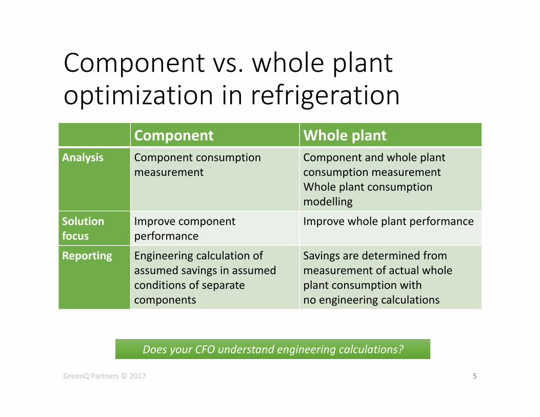
Component vs. whole plant optimization in refrigeration
Component Whole plant Analysis Component consumption
measurement Component and whole plant consumption measurement Whole plant consumption modelling
Solution focus
Improve component performance
Improve whole plant performance
Reporting Engineering calculation of assumed savings in assumed conditions of separate components
Savings are determined from measurement of actual whole plant consumption with no engineering calculations
5
Does your CFO understand engineering calculations? Does your CFO understand engineering calculations?
GreenQ Partners © 2017
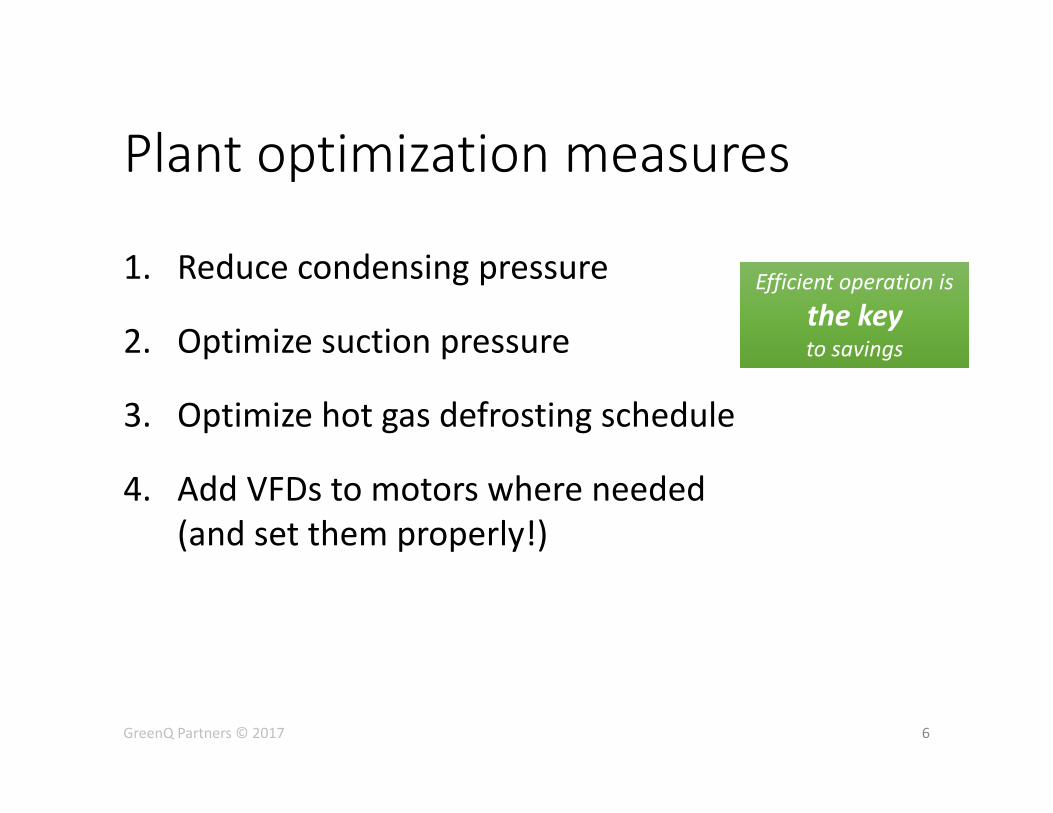
Plant optimization measures
1. Reduce condensing pressure
2. Optimize suction pressure
3. Optimize hot gas defrosting schedule
4. Add VFDs to motors where needed (and set them properly!)
6 GreenQ Partners © 2017
Efficient operation is the key to savings
Efficient operation is the key to savings
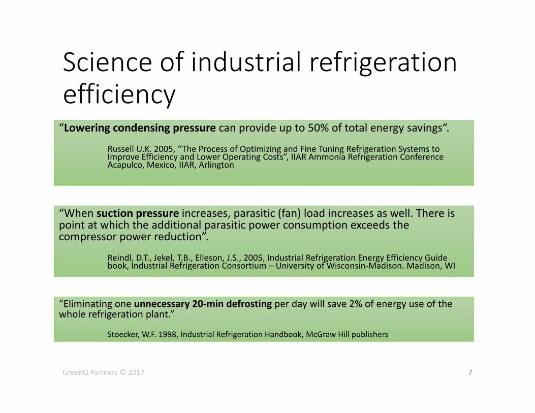
Science of industrial refrigeration efficiency “Lowering condensing pressure can provide up to 50% of total energy savings“.
Russell U.K. 2005, “The Process of Optimizing and Fine Tuning Refrigeration Systems to Improve Efficiency and Lower Operating Costs”, IIAR Ammonia Refrigeration Conference Acapulco, Mexico, IIAR, Arlington
7
“When suction pressure increases, parasitic (fan) load increases as well. There is point at which the additional parasitic power consumption exceeds the compressor power reduction”.
Reindl, D.T., Jekel, T.B., Elleson, J.S., 2005, Industrial Refrigeration Energy Efficiency Guide book, Industrial Refrigeration Consortium – University of Wisconsin‐Madison. Madison, WI
“Eliminating one unnecessary 20‐min defrosting per day will save 2% of energy use of the whole refrigeration plant.”
Stoecker, W.F. 1998, Industrial Refrigeration Handbook, McGraw Hill publishers
GreenQ Partners © 2017
Optimization of Refrigeration Plant Operation. Engineering Approach
32nd Annual Meeting International Institute of Ammonia Refrigeration March 14–17, 2010 2010 Industrial Refrigeration Conference & Exhibition Manchester Grand Hyatt San Diego, California http://www.iiar.org/IIAR/WCM/IIAR_Publications/IIAR_Technical_Papers/2010_Technical_Papers.aspx
Operating Ammonia Refrigeration Systems At Peak Efficiency
International institute of Refrigeration .Ammonia Refrigeration Technology. International Conference. Ohrid 2013 http://toc.proceedings.com/18495webtoc.pdf
Papers by Sergei Khoudiachov
GreenQ Partners © 2017 8
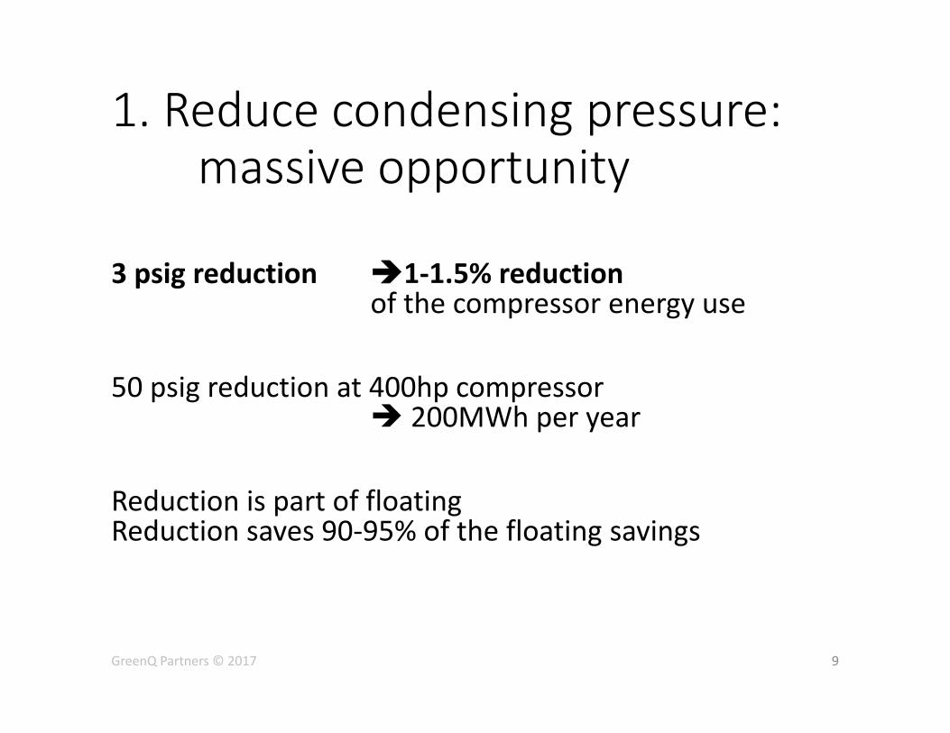
1. Reduce condensing pressure: massive opportunity
9
3 psig reduction 1‐1.5% reduction of the compressor energy use 50 psig reduction at 400hp compressor 200MWh per year Reduction is part of floating Reduction saves 90‐95% of the floating savings
GreenQ Partners © 2017
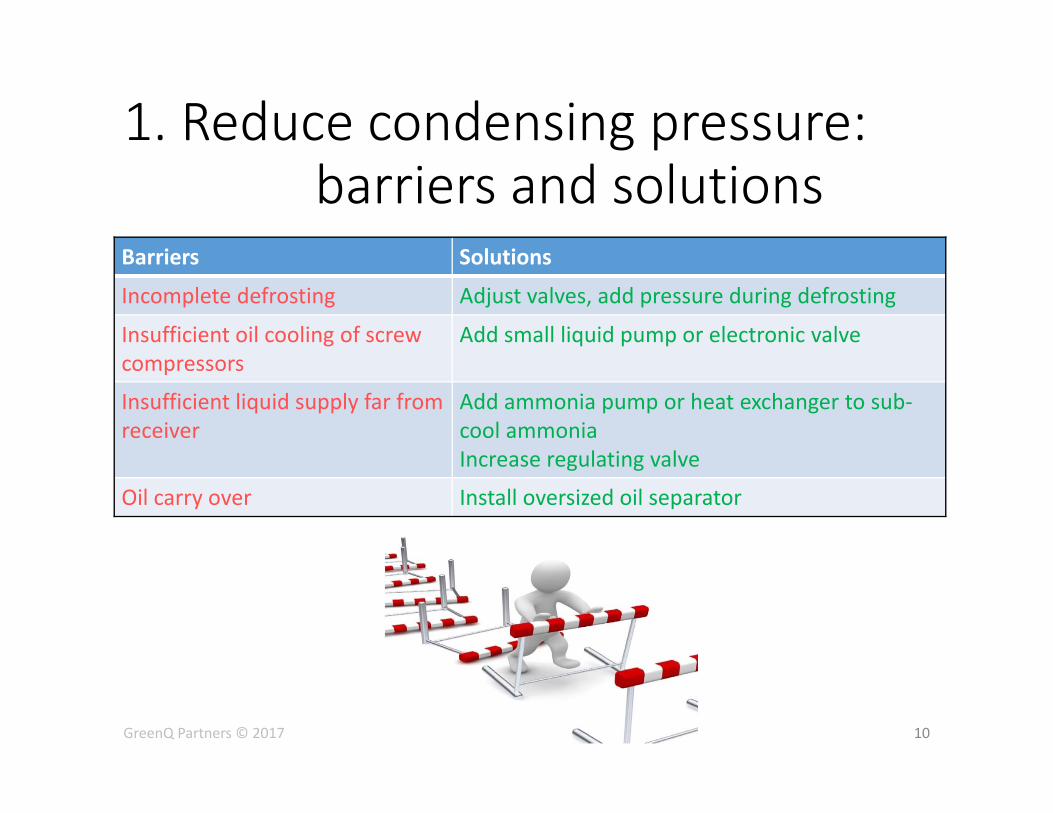
Barriers Solutions
Incomplete defrosting Adjust valves, add pressure during defrosting
Insufficient oil cooling of screw compressors
Add small liquid pump or electronic valve
Insufficient liquid supply far from receiver
Add ammonia pump or heat exchanger to sub‐cool ammonia Increase regulating valve
Oil carry over Install oversized oil separator
1. Reduce condensing pressure: barriers and solutions
10 GreenQ Partners © 2017
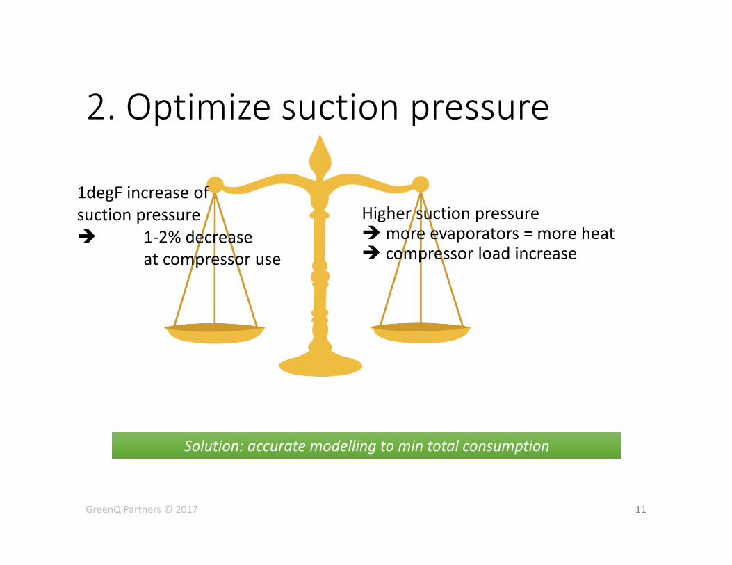
2. Optimize suction pressure
1degF increase of suction pressure 1‐2% decrease at compressor use
11
Higher suction pressure more evaporators = more heat compressor load increase
Solution: accurate modelling to min total consumption Solution: accurate modelling to min total consumption
GreenQ Partners © 2017
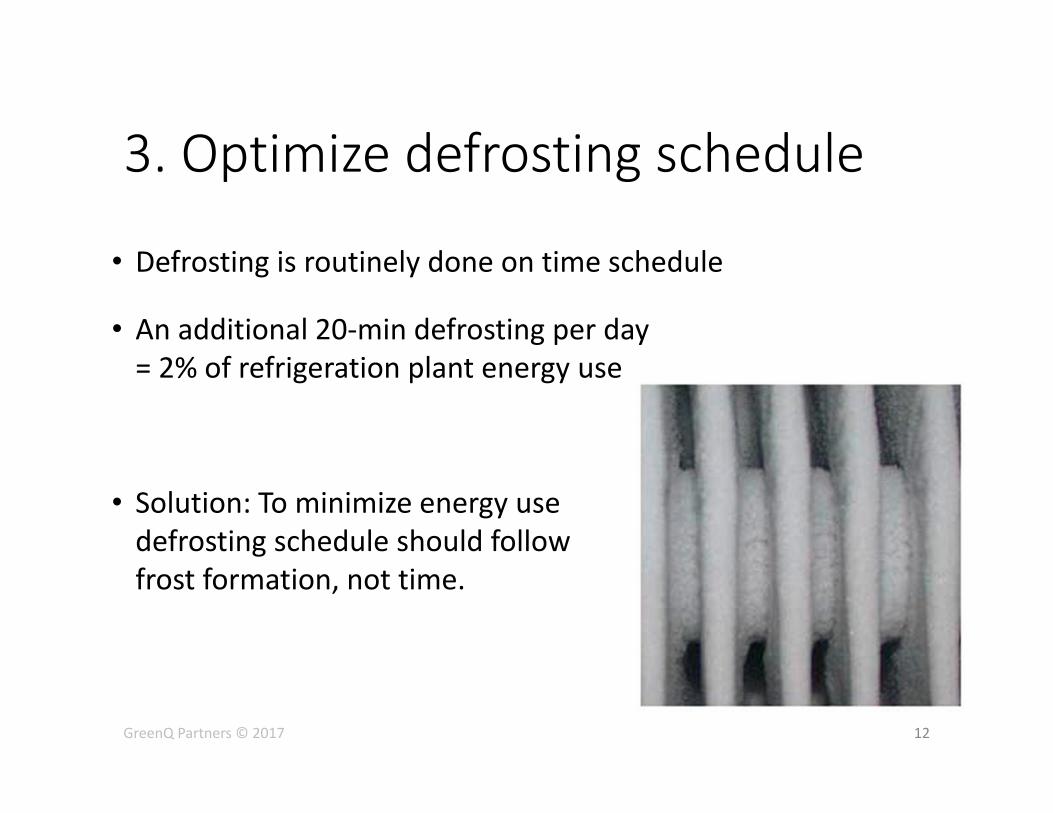
3. Optimize defrosting schedule
• Defrosting is routinely done on time schedule
• An additional 20‐min defrosting per day = 2% of refrigeration plant energy use
• Solution: To minimize energy use defrosting schedule should follow frost formation, not time.
12 GreenQ Partners © 2017
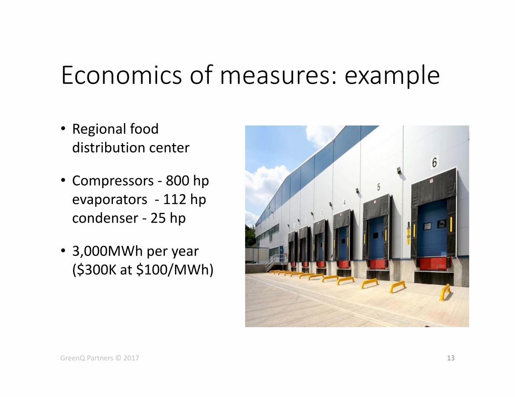
Economics of measures: example
• Regional food distribution center
• Compressors ‐ 800 hp evaporators ‐ 112 hp condenser ‐ 25 hp
• 3,000MWh per year ($300K at $100/MWh)
13 GreenQ Partners © 2017
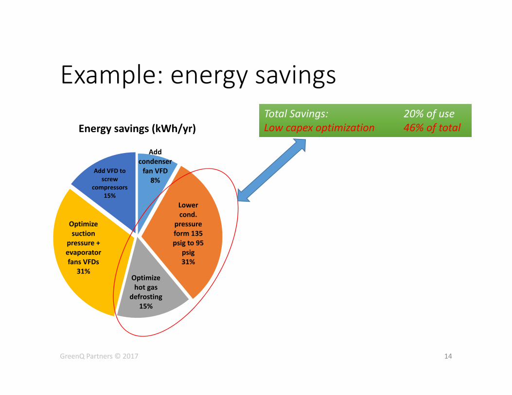
Example: energy savings
Add condenser fan VFD
8%
Lower cond.
pressure form 135 psig to 95
psig 31%
Optimize hot gas
defrosting 15%
Optimize suction
pressure + evaporator fans VFDs
31%
Add VFD to screw
compressors 15%
Energy savings (kWh/yr)
14
Total Savings: 20% of use Low capex optimization 46% of total Total Savings: 20% of use Low capex optimization 46% of total
GreenQ Partners © 2017
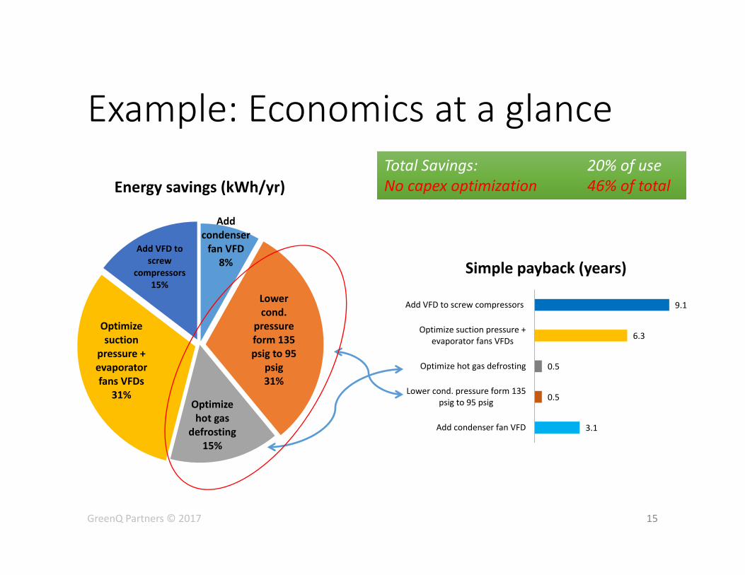
Example: Economics at a glance
Add condenser fan VFD
8%
Lower cond.
pressure form 135 psig to 95
psig 31%
Optimize hot gas
defrosting 15%
Optimize suction
pressure + evaporator fans VFDs
31%
Add VFD to screw
compressors 15%
Energy savings (kWh/yr)
15
Total Savings: 20% of use No capex optimization 46% of total Total Savings: 20% of use No capex optimization 46% of total
GreenQ Partners © 2017
3.1
0.5
0.5
6.3
9.1
Add condenser fan VFD
Lower cond. pressure form 135psig to 95 psig
Optimize hot gas defrosting
Optimize suction pressure +evaporator fans VFDs
Add VFD to screw compressors
Simple payback (years)
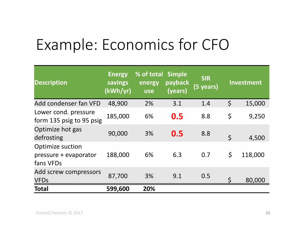
Example: Economics for CFO
Description Energy savings (kWh/yr)
% of total energy use
Simple payback (years)
SIR (5 years) Investment
Add condenser fan VFD 48,900 2% 3.1 1.4 $ 15,000 Lower cond. pressure form 135 psig to 95 psig 185,000 6% 0.5 8.8 $ 9,250
Optimize hot gas defrosting 90,000 3% 0.5 8.8
$ 4,500 Optimize suction pressure + evaporator fans VFDs
188,000 6% 6.3 0.7 $ 118,000
Add screw compressors VFDs 87,700 3% 9.1 0.5 $ 80,000 Total 599,600 20%
16 GreenQ Partners © 2017
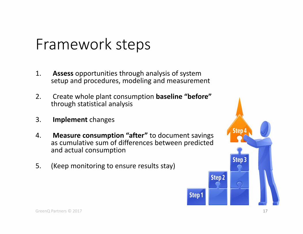
Framework steps
1. Assess opportunities through analysis of system setup and procedures, modeling and measurement
2. Create whole plant consumption baseline “before” through statistical analysis
3. Implement changes
4. Measure consumption “after” to document savings as cumulative sum of differences between predicted and actual consumption
5. (Keep monitoring to ensure results stay)
17 GreenQ Partners © 2017
Measurement is the key to prove results
18 GreenQ Partners © 2017
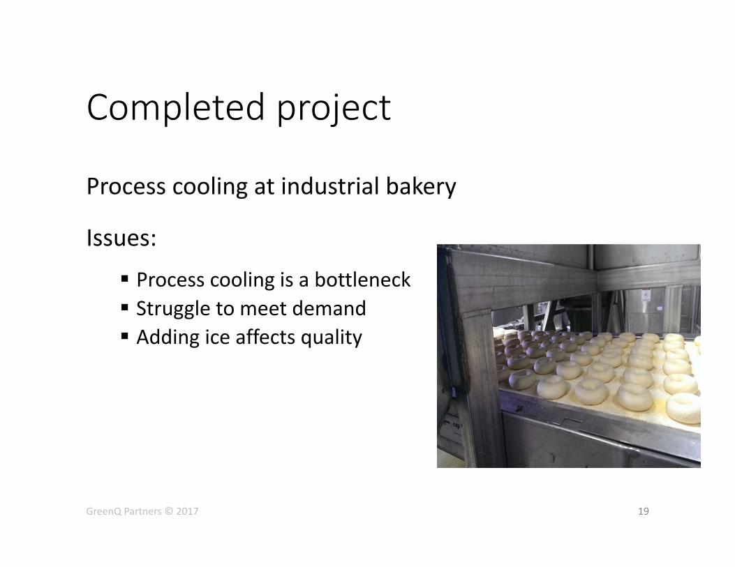
Completed project
Process cooling at industrial bakery
Issues:
Process cooling is a bottleneck Struggle to meet demand Adding ice affects quality
19 GreenQ Partners © 2017
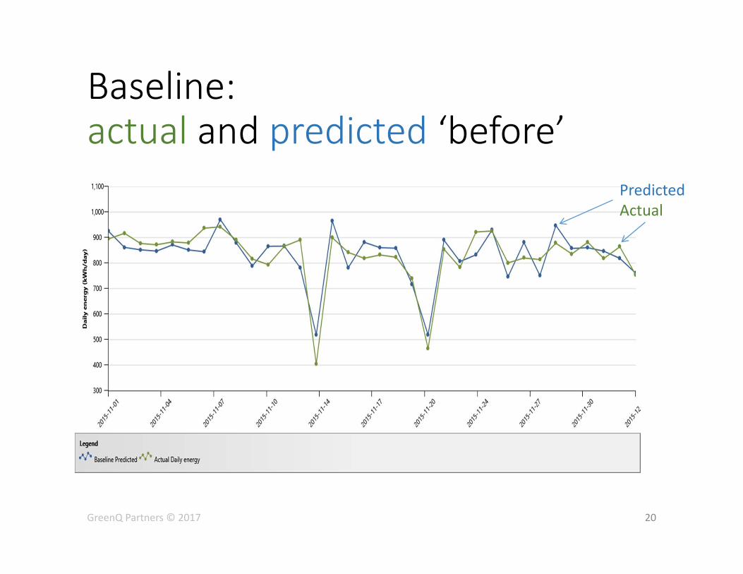
Baseline: actual and predicted ‘before’
20 GreenQ Partners © 2017
Predicted Actual
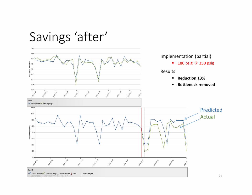
Savings ‘after’
21
Implementation (partial) 180 psig 150 psig
Results Reduction 13% Bottleneck removed
GreenQ Partners © 2017
Predicted Actual
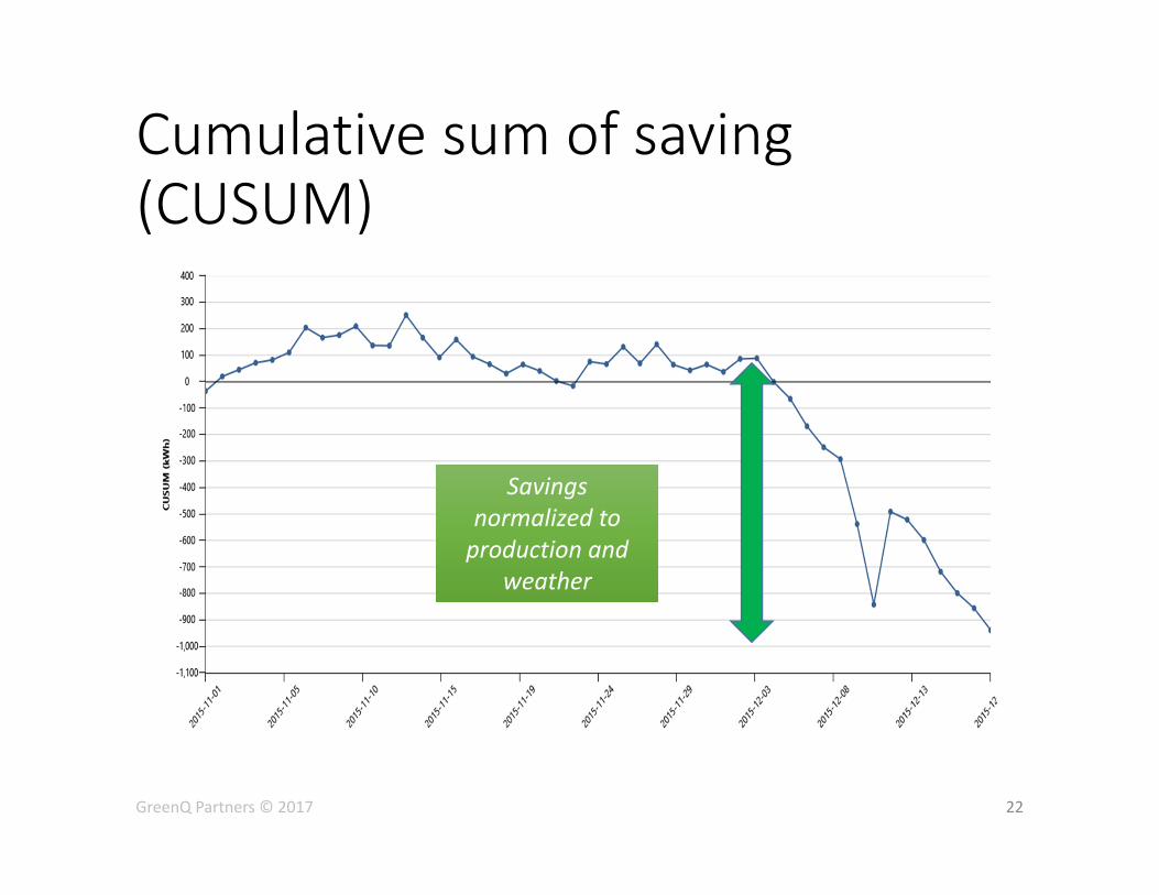
Cumulative sum of saving (CUSUM)
22
Savings normalized to production and
weather
Savings normalized to production and
weather
GreenQ Partners © 2017
GreenQ Partners © 2017 23
Summary
• 30% energy use reduction is possible though optimization
• Metering removes risks of hidden performance
• Current refrigeration contractor stays
• Incentives apply

Anatoli Naoumov, CMVP, MBA
416‐728‐7239
www.GreenQ.ca
24
To receive a copy of this presentation with links to reports, financial details of example, and detailed explanations on how suggested measures work –
Leave me your card marked ‘slides’
GreenQ Partners © 2017
Contact
Reduction of condensing pressure Overcoming barriers
• Not enough pressure for complete hot gas defrosting
Some operators report that hot gas defrosting cannot be completed when condensing pressure is low. This is only partially true: Often incomplete defrosting issue can be resolved through adjustment of defrosting valves. If incomplete defrosting still persists, condensing pressure can be slightly elevated for defrosting time and set back when defrosting is over through PLC.
• Insufficient oil cooling of screw compressors
This is likely the most common barrier to reduction of condensing pressure. Typically, at condensing pressure below 120 psig flow of liquid into the compressor will be limited by the thermal expansion valve. An addition of a small liquid ammonia pump or of an electronic expansion valve will remove this barrier.
• Insufficient liquid supply of ammonia far from receiver
We sometimes hear from operators that at condensing pressure below 120 psig, pressure difference 80‐90 psig, plants experience an undersupply of liquid ammonia to evaporators that are far away from receiver. This happens because liquid ammonia starts to evaporate in the pipe and vapour blocks liquid supply. This issue can be resolved through additional cooling of liquid ammonia below saturation temperature or by increasing the size of the regulating valve. Sub cooling can be achieved through installation of heat exchanger or ammonia pump.
• Oil carry over into ammonia through separator
At low condensing pressure gas density decreases and velocity increases. High gas velocity can cause oil carry over into ammonia system. This barrier can be removed by installation of oversized oil separator or by reducing mass flow of the refrigerant.
25 GreenQ Partners © 2017
Reduction of condensing pressure
26
Floating vs. reduced condensing pressure
Floating condensing pressure consists of two steps:
• lowering condensing pressure and
• actual floating.
Typically, lowering condensing pressure can provide 90‐95% of energy savings. Actual floating can give us just 5‐10% of the savings. Why does it happen? Lower condensing pressure reduces energy use by compressors, while floating condensing pressure reduces energy use by condensers. Usually, nominal power of condensers is about 10% of compressors’ power.
Additionally, floating can be activated only during short periods of the year. During summer, no floating is possible, because condensers typically run at full capacity to keep required condensing pressure. During winter, no floating is possible because refrigeration plants operate at minimum allowable condensing pressure. During fall and spring, floating can be activated, when condenser capacity exceeds optimum. However, floating will never be activated if a refrigeration plant has undersized condensers.
GreenQ Partners © 2017
Optimize suction pressure It is a common knowledge, that raising suction pressure, often measured as suction temperature, reduces energy consumption at compressor. Typically, reduction is 1‐2% per 1 degF increase in suction temperature. Increase of suction pressure does not come free; therefore, efficiency of the whole refrigeration plant should be considered to determine the optimum suction pressure. This is not a trivial decision.
Higher suction pressure will reduce temperature difference between suction temperature and air temperature in the refrigerated room. To keep the required refrigeration capacity more evaporators will be running. Therefore, fans will use more energy and release more heat in refrigerated room. This will cause a need for additional compressor energy to compensate this parasitic refrigeration load.
To estimate plant performance at a higher suction pressure, energy saved by compressors should be compared to energy used by additional evaporator fans. Sometimes, increase of energy use at evaporator fans exceeds saving at compressors. Power of evaporator fans determines optimum suction pressure.
Optimal value of suction pressure should be determined for each plant through accurate modeling.
27 GreenQ Partners © 2017
28
Optimize Hot Gas Defrosting frequency Hot gas defrosting requires temporary heating parts of plant that are cold during the regular work cycle. In our experience, the procedure is routinely done on time schedule, while from energy use perspective it should be done on as‐needed basis: often in summer and rarely in winter.
Defrosting is needed to eliminate frost from evaporator coils. Too much frost kills efficiency of evaporators. On the other hand, defrosting itself costs energy.
Defrosting is a highly inefficient procedure in terms of energy: from every 100 units of heat provided by hot gas, less than 20 units will melt frost, the remaining 80 units will warm up parts of the system. These 80 units must be removed by the refrigeration plant during the regular operation. After 35 minutes of hot gas defrosting, the evaporator coil, as well as part of refrigeration plant, will run for the next 1 hour in a cooling mode to remove the heat of defrosting. As a rule of thumb, eliminating one unnecessary defrosting per day saves 3% of whole refrigeration plant energy use.
Frequency of defrosting should be set to minimize total energy losses from frost and hot gas defrosting procedure. We recommend accurate plant‐specific modeling to determine this frequency.
GreenQ Partners © 2017
Screw compressor VFD VFDs can be installed for refrigeration compressors. These compressors have constant torque loads. With constant torque loads, the torque loading is not a function of speed. As the speed changes, the load torque remains constant and energy use changes linearly with speed. This means that at 50% speed the compressor will use 50% energy. There is no energy saving benefits of using VFDs for reciprocated compressors, unless you want gradual change capacities of these compressors.
Typically, screw compressors use slide valves to reduce capacity. Capacity can be changed gradually but energy efficiency will suffer. This energy efficiency will be reduced gradually (linearly) by unloading screw compressor from 100% to 50%. It will be reduced exponentially when compressor capacity is below 50%.
How much energy can be saved by compressor VFD?
This depends of average compressor load and operating compression ratio. Compressor VFD helps to recover losses related to part load operation of this compressor. The losses are greater when compressor operate at low capacity (below 50%) and at high compression ratio. It means that if compressor operate long time at low capacity and high compression ratio energy saved by VFD will be good. If compressor operate at high capacity and at low compression ratio energy saved by VFD will be minimal. Don’t forget that VFD itself use additional 3 – 3.5% of energy.
29 GreenQ Partners © 2017
Fan VFDs VFDs can be helpful to recover losses related to part load operation (compressors, condensers, evaporators). How great are the energy losses related to part load operation?
If plant is poorly designed and/or poorly operated, energy losses will be great and a lot of energy can be recovered through the use of VFDs and they will have a relatively short payback. If plant has a good design and is operated well, energy losses will be minimal and little energy can be recovered. Payback for an investment in VFDs for this plant will be very long. Plant design and plant operation are two major factors to determine VFDs’ payback.
Condenser fan VFDs can save up to 8% of a refrigeration plant’s energy use. But typically, the energy savings will be significantly lower because the operating time at favorable energy saving conditions will be short. During summer operation, the majority of refrigeration plants run condensers at full capacity. Very little energy can be saved during summer time. During winter operation, many condensers use little energy. This means that energy losses of part load operation are minimal and little energy can be recovered. During spring and fall some refrigeration plants can get good energy savings from condenser fan VFDs, especially plants with centrifugal condenser fans. To get maximum savings from condenser fan VFDs, condensers should not be undersized.
Evaporator fan VFDs can be useful to save energy, especially for evaporator coils located in penthouses. Electrical motors of these evaporator fans, typically, are oversized. Many designers are over focused on air throw and little attention is paid to natural air convection. Typically, penthouses are located in the middle of a cold room and the warmest air located under the ceiling is pulled evenly from each side of the room. This factor helps prevent hot spots in a refrigerated room with penthouses and many evaporator fans can operate successfully at a low speed. Ceiling hung evaporator fans should have a good throw to push warm air from the opposite upper corner of a cold room. Modern cold rooms with penthouses are typically high‐rise construction. During the cooling mode, the room height will help to natural air convection and the warmest air will always enter the evaporators.
30 GreenQ Partners © 2017