Embed Size (px)
Citation preview

TiN coating of the CSNS ceramic vacuum chambers
Haiyi DongInstitute of High Energy Physics, CAS
9/28/2015

Page散裂中子源进展汇报 October 8, 2015 2
Outline
• CSNS Project
• Ceramic chambers
• Setup of TiN coating
• Analysis of the samples
• Summary

Page散裂中子源进展汇报 October 8, 2015
Schematic layout of CSNS facilities
3
China Spallation Neutron Source (CSNS) is designed to accelerate proton beam pulses to 1.6GeV kinetic energy with a beam power of 100kW at 25Hz repetition rate, striking a solid metal target to produce spallation neutrons. H- are firstly generated from a Penning ion source. RFQ forms beam bunches and accelerates the beam to 3 MeV. DTL tanks further increase the beam energy to 80 MeV. A long beam transport line is followed with the DTL to send the beam to a rapid cycling synchrotron (RCS) accelerator. The H- beam is stripped to become proton beam and injected into the RCS ring. In the ring the proton beam is accumulated to a high current pulse and then accelerated to 1.6 GeV. The high-energy proton beam extracted from the RCS bombards on the target to generate neutrons through spallation reaction.
Page散裂中子源进展汇报 October 8, 2015 4
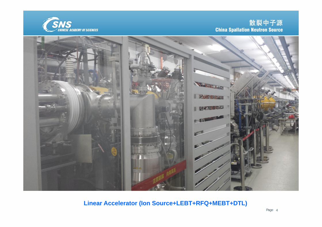
Linear Accelerator (Ion Source+LEBT+RFQ+MEBT+DTL)

Page散裂中子源进展汇报 October 8, 2015 5
LRBT vacuum system

Page散裂中子源进展汇报 October 8, 2015 6
Rapid Cycling Synchrotron (RCS)

Page散裂中子源进展汇报 October 8, 2015
2. Ceramic chambers
• The ceramic chambers were chosen in the dipole and quadrupole magnets to reduce the eddy-current effect which will produce the perturbation of magnetic fields and the large ohmic losses.
• The quadrupole ceramic chambers have been fabricated by metallizing and brazing.
• The glass joint has been adopted for the CSNS dipole ceramic chambers since this method is considerably less expensive and relatively simple than that of metallizing the ceramic pipe ends and brazing them together.
• Metal seal of Helicoflex Delta type and demountable chain clamp are used for the quick disconnect flanges.
• A new RF shielding method for the ceramic chambers has been developed.
7

Page散裂中子源进展汇报 October 8, 2015 8
Quadrupole Ceramic Vacuum Chamber
Glass jointLaser welding
Cu-Ag brazing

Page散裂中子源进展汇报 October 8, 2015 9
Dipole Ceramic Vacuum Chamber
• A 2.8m-long dipole ceramic chamber consists of 8 ceramic tubes with 15 bending .
• Each end of the ceramic tube is ground flat and glazed with a thin layer of suitable glass.
• The ceramic flange is also joined to the ceramic tubes by glass brazing in the air furnace of 1200C.

Page散裂中子源进展汇报 October 8, 2015 10
Types of Ceramic Chambers
MB QA QB QC QD INB1 INB2 QKA QKB
Drawings No. ACVA-****-0000
1101 1102 1103 1104 1105 1106 1107 1108 1109
Flange Sizes KF250 KF250 KF250 KF250 KF250 KF200KF200 CF150
KF250 KF250
Numbers of Installation 24 15 15 8 8 3 1 1 1Numbers of Spares 2 1 1 1 1 1 1 1 1
Numbers of manufacture 26 16 16 9 9 4 2 2 2
Length (mm) 2775 780 1535 1540 1205 1070 1415 740 1520
Outer Diameter (mm) 152×248 198 264 214 245 178 165 198 264
Inner Diameter (mm) 135×218 183 249 199 230 163 150 183 249
Wall Thickness (mm) 8.5×15 7.5 7.5 7.5 7.5 7.5 7.5 7.5 7.5
Numbers and Types of the CSNS Ceramic Vacuum Chambers

Page散裂中子源进展汇报 October 8, 2015 11
• The total leak rate of the dipole ceramic chamber is less than 2×10-11 Pam3/s
• The ultimate pressure of the ceramic chamber reached 5×10⁻⁸ Pa after 48h bakeout at 160C.
• The outgassing rate of the inner surface of the ceramic chamber is less than 5×10-13 Pam3/scm2.

Page散裂中子源进展汇报 October 8, 2015 12
RF shielding prototype of a dipole ceramic chamber
• RF copper strips with a length of 3m were cut with water according to the shape of a dipole ceramic chamber. • 8 sheets of RF copper strips with 3 types were fixed on the surface of ceramic chamber by kapton film knitting.• Advantage: no soldering points, cost-efficient.

Page散裂中子源进展汇报 October 8, 2015 13
3. Setup of TiN coating for the ceramic chambers
• A thin TiN layer of about 100 nm in thickness was coated in order to minimize the secondary electron yield (SEY) and prevent the charges from building-up in the inner surface.
• DC magnetron sputtering has been adopted to coat TiN inside the ceramic chambers.
• The equipment of TiN coating consists of Ti cathodes with magnets and copper anodes outside the ceramic chambers.

Page散裂中子源进展汇报 October 8, 2015 14
Ti Cathode and vacuum seal assembly
• The magnets inserted inside Ti cathode are stacked with opposing poles, resulting in a looping magnetic field of sufficient strength on the cathode surface.
• Ti cathode is insulated with vacuum chamber by teflon and sealed by viton ring.
• A cooling water tube is needed to cool down Ti cathode during DC magnetron sputtering.

Page散裂中子源进展汇报 October 8, 2015 15
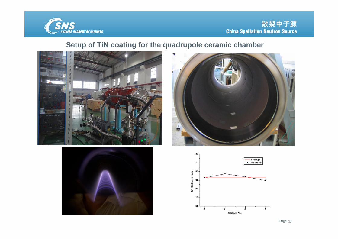
TiN coating for the quadrapole ceramic chamber
An anode screen made of thin copper sheet of 1 mm in thickness is wrapped outside the ceramic chamber in order to produce an electric field with the Ti cathode. This will result in a uniform thickness of TiN along the ceramic chamber. The uniformity of TiN thickness is better than 10, and the ratio of Ti and N is about 0.93.
SNS
J-PARC
CSNS

Page散裂中子源进展汇报 October 8, 2015 16
The electric field simulation for TiN coating of the quadrapole ceramic chamber(CST)
An anode grid inside chamber(2100V/m) An Anode screen outside chamber(1956V/m) No anode(1561V/m)

Page散裂中子源进展汇报 October 8, 2015 17
Ar+ discharge plasma distribution on the surface of a cathode(COMSOL Multiphysics)
Page散裂中子源进展汇报 October 8, 2015 18
Setup of TiN coating for the quadrupole ceramic chamber

Page散裂中子源进展汇报 October 8, 2015 1919
Left cathode(7.5)
Right cathode(7.5)
N2/Ar inlet
Cathode supports
TiN coating setup for a full-scale dipole ceramic chamber

Page散裂中子源进展汇报 October 8, 2015
TiN coating for the CSNS dipole ceramic chamber
• Two bending magnetron sputtering cathodes with a curve of 7.5 were inserted inside the dipole ceramic chamber symmetrically. • An anode screen made of thin copper sheet of 1 mm in thickness is wrapped outside the ceramic chamber in order to produce
an electric field with the Ti cathode. • The uniformity of TiN thickness is better than 50, and the ratio of Ti and N is about 0.92.

Page散裂中子源进展汇报 October 8, 2015 21
5.00E‐03
5.00E‐02
5.00E‐01
5.00E+00
5.00E+01
5.00E+0214:38:02
14:39:34
14:41:06
14:42:38
14:44:10
14:45:42
14:47:14
14:48:46
14:50:18
14:51:50
14:53:22
14:54:54
14:56:26
14:57:58
14:59:30
15:01:02
15:02:34
15:04:06
15:05:38
15:07:10
15:08:42
15:10:14
15:11:46
15:13:18
15:14:50
15:16:22
15:17:54
15:19:26
15:20:58
15:22:30
15:24:02
15:25:34
15:27:06
15:28:38
15:30:10
15:31:42
15:33:14
15:34:46
15:36:18
15:37:50
15:39:22
15:40:54
Voltage(V)
Current(A)
Pressure(mbar)
Ar(sccm)
N2(sccm)
TiN coating parameters for the dipole ceramic chamber
Coating Ti and TiN with cathode 1 Coating Ti and TiN with cathode 2
390V
4.4sccm
2.3sccm
7E-3 mbar
7A

Page散裂中子源进展汇报 October 8, 2015
4. Analysis of the TiN-coating samples
• TiN film thickness
• XPS measurements for TiN film Composition
• Secondary Electron yields
22

Page散裂中子源进展汇报 October 8, 2015 23
TiN coating samples for the dipole ceramic chamber
TiN film thickness (44nm~135nm)

Page散裂中子源进展汇报 October 8, 2015 24
Observation of digital metallurgical microscope for the ceramic samples with and w/o TiN film
Ceramic sample Ceramic sample coated with TiN

Page散裂中子源进展汇报 October 8, 2015 25
0.00E+00
2.00E+04
4.00E+04
6.00E+04
8.00E+04
1.00E+05
1.20E+05
1.40E+05
010020030040050060070080090010001100
Cou
nts
/ s
Binding Energy (eV)
Survey1 Scan, 55.5 s, 500µm, CAE 100.0, 1.00 eV
92.028.19
78.17
N
Ti
XPS spectrum for TiN film composition measurement

Page散裂中子源进展汇报 October 8, 2015 26
SEY measurements for the ceramic samples with and w/o TiN coating
Ceramic sample
5.821.92~2.06
Ceramic sample coated by TiN

Page散裂中子源进展汇报 October 8, 2015 27
TiN coating for the CSNS Extraction kicker Ferrites

Page散裂中子源进展汇报 October 8, 2015
5. Summary
• Most of the CSNS equipment have been produced and begun to install. The normal operation for user is foreseen in 2018.
• Both the dipole and quadrupole ceramic chambers have been coated with TiN by magnetron sputtering. Especially for the dipole ceramic chambers, two curved Ti cathodes of 7.5 were used.
• The thickness, composition and SEY for the samples coated with TiN have been measured. The results meet the requirements.
• Making use of the Ti cathode for coating the quadrupole ceramic chambers, the CSNS Extraction kicker Ferrites were coated with TiN to reduce SEY.
• The TiN coating of 86 ceramic chambers has almost been completed.
28