Embed Size (px)
Citation preview
Instructions for use
Title Massive Injection of Auxiliary Reducing Agent at Blast Furnace for the Sustainable Development
Author(s) 村井, 亮太
Issue Date 2016-09-26
DOI 10.14943/doctoral.k12451
Doc URL http://hdl.handle.net/2115/63326
Type theses (doctoral)
File Information Ryota_Murai.pdf
Hokkaido University Collection of Scholarly and Academic Papers : HUSCAP
Massive Injection of Auxiliary Reducing
Agent at Blast Furnace for the Sustainable
Development
Ryota MURAI
Laboratory of Energy Media
Hokkaido University
2016
R.Murai, “Massive Injection of Auxiliary Reducing Agent at Blast Furnace for the
Sustainable Development.”
2
CONTENTS
Chapter 1 General Introduction………………………………………………………… 6
1. 1 Current status of global warming and the roles to be performed by steel
making industries……………..……………………………………………………… 6
1. 2 Review on resent technologies of auxiliary reducing agent injection to blast
furnace……...……………..………………................................................................... 9
1. 2. 1 Liquid auxiliary reducing agent injection……………………………….9
1. 2. 2 Solid auxiliary reducing agent injection…………………………………9
1. 2. 3 Gas auxiliary reducing agent injection……………………………...… 11
1. 3 Roles of oxygen on the auxiliary reducing agent reaction and conventional
oxygen production methods………………………………………………..………..11
1. 3. 1 Reaction of auxiliary reducing agent and oxygen………………….… 11
1. 3. 2 Conventional oxygen production method…...………………………… 14
1. 4 Needs of furnace wall protection under massive injection of auxiliary
reducing agent…………………………………………..…………………………… 17
1. 4. 1 Accumulation of fine in a blast furnace and gas flow segregation
toward wall side…………………………………….………………………....… 17
1. 4. 2 Overview of conventional cooling system of blast furnace………..… 18
1. 5 Purpose and contents of this thesis……………………………………...…… 19
Chapter 2 Enhancement of combustion efficiency to increase in injection amount of
auxiliary reducing agents to a blast furnace…………………………………….…… 28
2. 1 Introduction…………………..…………………………………………….…… 28
2. 2 Concept of particle dispersion enhancement by convergent – divergent
lance………………………………………………..……………………….………… 30
2. 2. 1 Flow separation in divergent lance……………………………………. 30
2. 2. 2 Particle flow control by convergent lance…….………………..……… 32
R.Murai, “Massive Injection of Auxiliary Reducing Agent at Blast Furnace for the
Sustainable Development.”
3
2. 3 Direct observation of flow behavior of pulverized coal particle……………. 34
2. 3. 1 Experimental apparatus………………………………………..………. 34
2. 3. 2 Design of lance tip……………………………………………..………… 35
2. 4 Study on dispersibility and combustion behavior of pulverized coal by hot
model experiment………………………………………..………………….………. 38
2. 4. 1 Outline of hot model experimental furnace………………...………… 38
2. 4. 2 Evaluation of particle dispersion……………………………….……… 41
2. 4. 3 Effect of particle dispersibility on coke replacement ratio of pulverized
coal in hot model experiment………………………………………...………… 42
2. 5 Application of convergent – divergent lance to actual blast furnace……… 44
2. 5. 1 Evaluation of particle dispersibility at actual blast furnace………... 44
2. 5. 2 Change in permeability and coke replacement ratio at actual blast
furnace by use of convergent-divergent injection lance………………..….… 47
2. 6 Conclusions…………………………………………………………………...… 50
Chapter 3 Flow behavior of plastic particle as auxiliary reducing agent in the blast
furnace…………………………………………………………………………………… 53
3. 1 Introduction…………………………………………………………………...…53
3. 2 Characteristics of plastic gasification…………………………………...…… 55
3. 2. 1 Modeling of plastic gasification………………….…………….…..…… 55
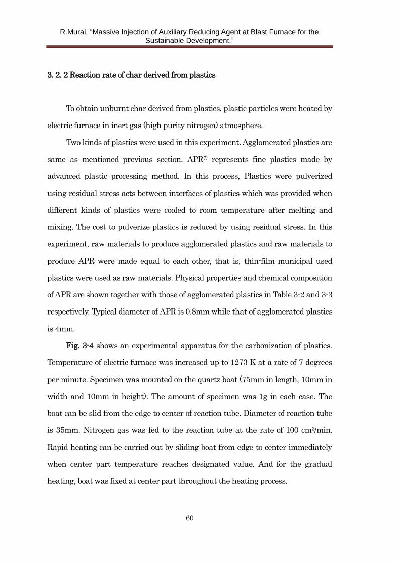
3. 2. 2 Reaction rate of char derived from plastics………………...…….…… 60
3. 3 Modeling of flow behavior of plastic particles in the lower part of blast
furnace…………………………..……………………………………….…………… 65
3. 4 Effect of initial plastic size on the operation of actual blast furnace……… 76
3. 5 Conclusions…………………………………………………………..…………. 78
Chapter 4 Solution combustion synthesis of Ca2AlMnO5 as an oxygen storage
material………………………………………..………………………………………… 85
R.Murai, “Massive Injection of Auxiliary Reducing Agent at Blast Furnace for the
Sustainable Development.”
4
4. 1 Introduction………………………………………………………………..…… 85
4. 2 Experiment………………………………………………………….…….……..87
4. 2. 1 Sample preparation…………………………………………………....... 87
4. 2. 2 Material characterization………………………….…………………… 89
4. 3 Results and Discussion……………………………………………………….... 91
4. 3. 1 Effect of on the behavior of oxygen storage…………………… …….91
4. 3. 2 Effect of periods of heat – treatment…………………………………... 99
4. 4 Conclusions……………………………………………………………………. 105
Chapter 5 Development of new cooling system to increase injection amount of
auxiliary reducing agent to blast furnace……………………………………………108
5. 1 Introduction…………………………………………………………………… 108
5. 2 Effect of operational condition of blast furnace on heat load to furnace
wall………………………………………………………………………………...…109
5. 3 Development of cast copper CS………………………………….………. .….113
5. 3. 1 Concept of enhancing durability of CS………………………………..113
5. 3. 2 Analysis of heat transfer and thermal stress of CS………………… 114
5. 4 Long-term wear resistance evaluation of CS at an actual blast furnace.. 117
5. 5 Comparative examination of copper CS and cast iron CS at actual blast
furnace…………………………..………………………………………………… ...119
5. 5. 1 Method of the examination………………………….…………. …...…119
5. 5. 2 Trends of CS body temperature………………………………… .……120
5. 5. 3 Evaluation of heat removal amount of CS.………………………….. 121
5. 6 Estimation and comparison of CS deformation behavior………...…… ….126
5. 7 Effect of copper CS on the operation of actual blast furnace……………... 127
5. 8 Conclusions……………………………………………………………………. 128
Chapter 6 Mitigation of carbon dioxide emission by integrating intensive injection
R.Murai, “Massive Injection of Auxiliary Reducing Agent at Blast Furnace for the
Sustainable Development.”
5
of auxiliary reducing agent and low reducing agent rate operation at blast
furnace………………………………..…………………………………….…………... 133
6. 1 Introduction…………………………………………………...………………. 133
6. 2 Optimization of solid auxiliary reducing agent combustion……………… 134
6. 2. 1 Concept of simultaneous injection of pulverized coal and used
plastics………………………………………………………...….……………... 134
6. 2. 2 Improvement of combustibility by simultaneous injection of
pulverized coal/used plastics………………………………...………………... 136
6. 2. 3 Improvement of combustibility by simultaneous injection of solid/gas
auxiliary reducing agents…………………………………………................... 143
6. 3 Relationship of blast furnace operational condition and the CO2 emission
………………………………………………………………………..……………… 147
6. 3. 1 Evaluation of CO2 emissions by RIST diagram…………………….. 147
6. 3. 2 Effect of hydrogenous reducing agent on CO2 emissions……...........156
6. 3. 3 Effect of low temperature operation on CO2 emissions……………..157
6. 3. 4 Evaluation of carbon dioxide emissions in various operation
conditions……………………………………………………………………….. 158
6. 4 Design of innovative blast furnace process considering top gas recycling.160
6. 5 Carbon balance in steelmaking works…………….………………………... 164
6. 6 Concept of innovative blast furnace integrated with co-generating oxygen
production system……………………………..…………………………………... 166
6. 7 Conclusions……………………………………………………………………. 167
Chapter 7 General conclusions………………………………………………………. 172
List of Publications related to the dissertation…………...…..…………………….. 177
Acknowledgement…………………………………….……………………………….. 178
R.Murai, “Massive Injection of Auxiliary Reducing Agent at Blast Furnace for the
Sustainable Development.”
6
Chapter 1 General Introduction
1. 1 Current status of global warming and the roles to be performed by steel
making industries
Considerable effort has been made to cope with global warming problem all
over the world. The 2015 United Nations Climate Change Conference, COP 21
was held in Paris in late 2015. Several countermeasures were agreed among
representatives of the 196 parties who participated in the conference. For example,
goal of limiting global warming was set to less than 2 degrees Celsius and they
pursue efforts to limit the temperature increase to 1.5 degrees Celsius. In addition,
zero net anthropogenic greenhouse gas (GHG) emissions was mentioned as a
long-term challenge1).
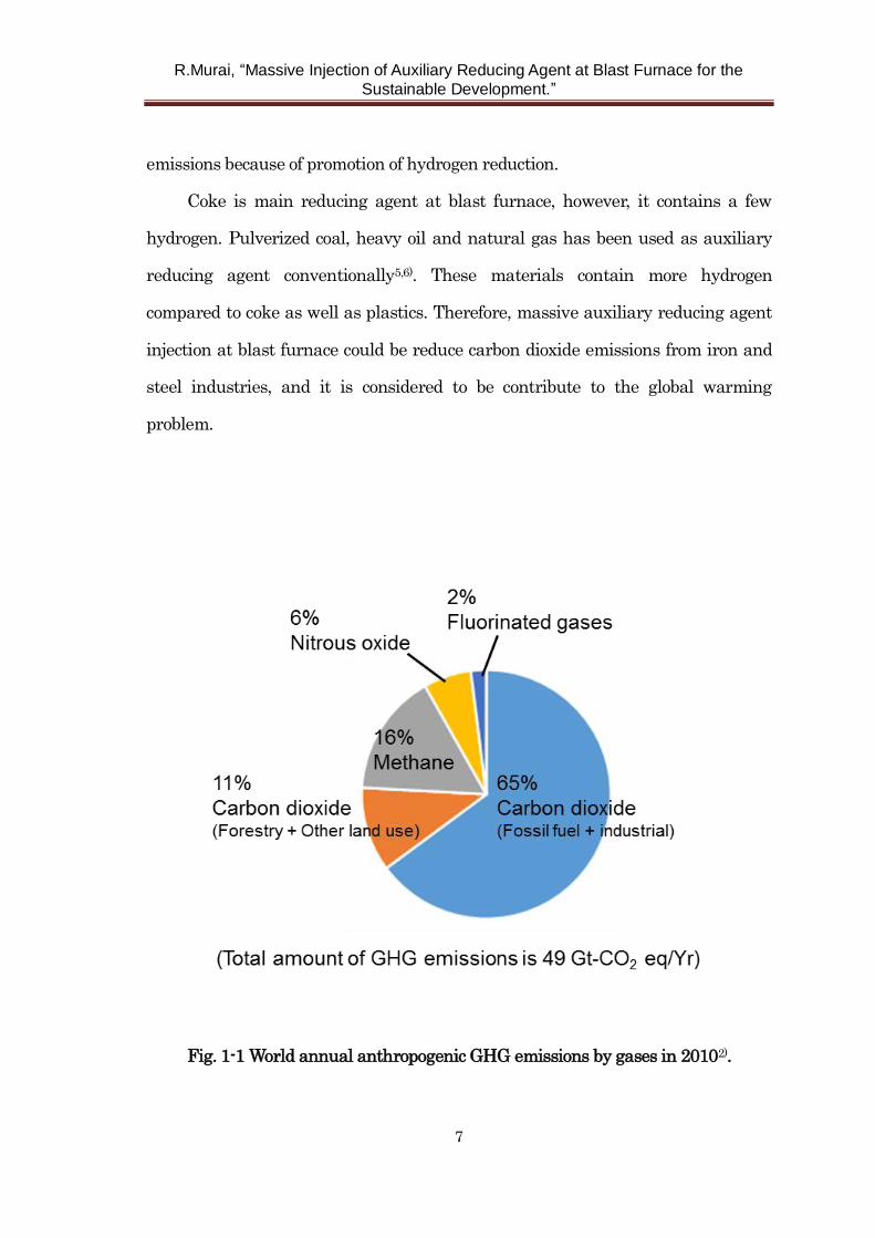
Fig. 1-1 shows total annual anthropogenic GHG emissions by gases in 20102).
Although there are several GHG such as carbon dioxide, methane, nitrous oxide
and fluorinated gases, carbon dioxide occupies the majority of them. Therefore, it is
considered that significance of carbon dioxide mitigation is extremely great.
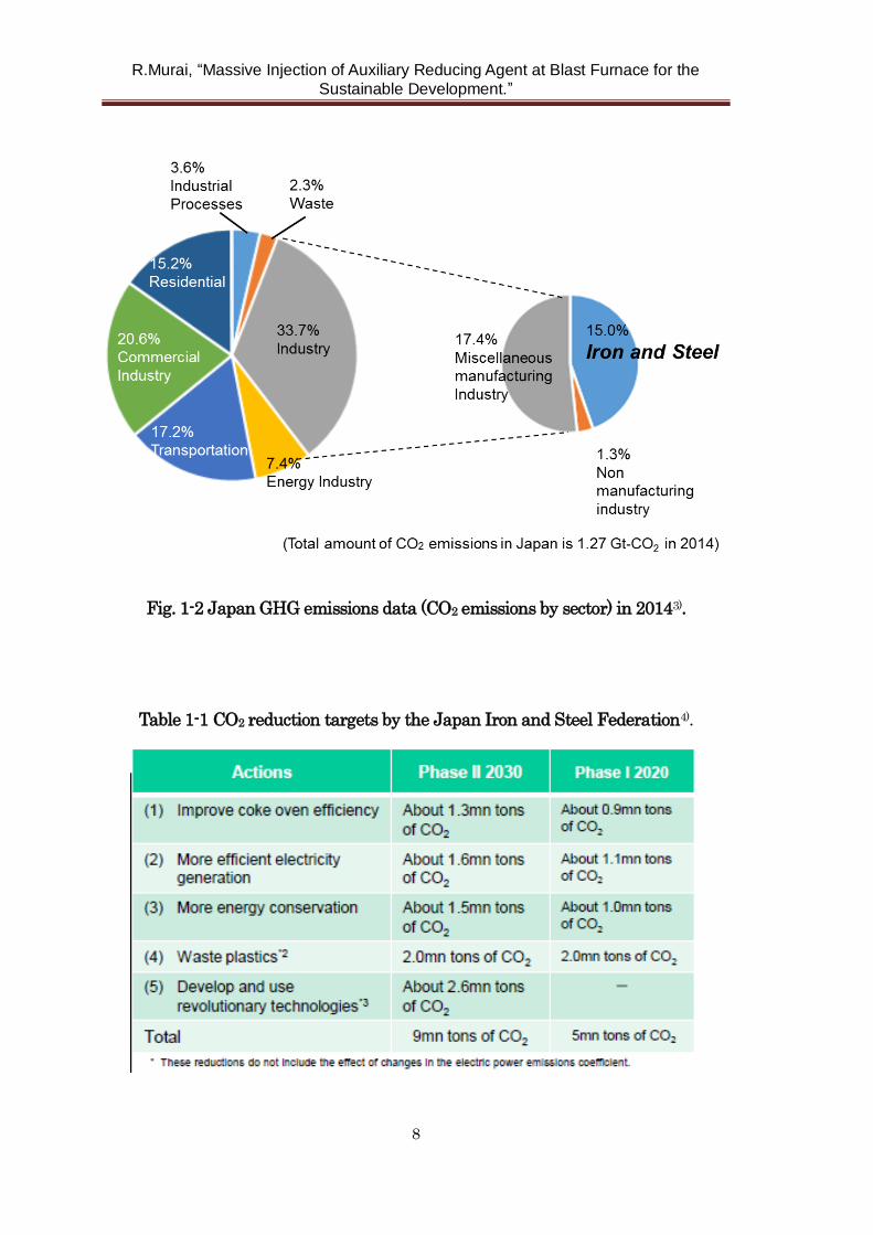
As shown in Fig. 1-2, total amount of carbon dioxide emission in Japan was
1.27 Gt-CO2 in 2014, and share of iron and steel making industry accounts for
15%3). This value is the largest among the industry sector.
The Japan Iron and Steel Federation announced “Report of Commitment to a
Low Carbon Society” in January 20154). It consists of improvement of coke oven
efficiency, more efficient electricity generation, more energy conservation, use of
used plastics and development and use revolutionary technologies (Table 1-1).
Used plastics contain large amount of hydrogen compered to coke. Use of used
plastics as auxiliary reducing agent at blast furnace may reduce carbon dioxide
R.Murai, “Massive Injection of Auxiliary Reducing Agent at Blast Furnace for the
Sustainable Development.”
7
emissions because of promotion of hydrogen reduction.
Coke is main reducing agent at blast furnace, however, it contains a few
hydrogen. Pulverized coal, heavy oil and natural gas has been used as auxiliary
reducing agent conventionally5,6). These materials contain more hydrogen
compared to coke as well as plastics. Therefore, massive auxiliary reducing agent
injection at blast furnace could be reduce carbon dioxide emissions from iron and
steel industries, and it is considered to be contribute to the global warming
problem.
Fig. 1-1 World annual anthropogenic GHG emissions by gases in 20102).
R.Murai, “Massive Injection of Auxiliary Reducing Agent at Blast Furnace for the
Sustainable Development.”
8
Fig. 1-2 Japan GHG emissions data (CO2 emissions by sector) in 20143).
Table 1-1 CO2 reduction targets by the Japan Iron and Steel Federation4).
R.Murai, “Massive Injection of Auxiliary Reducing Agent at Blast Furnace for the
Sustainable Development.”
9
1. 2 Review on resent technologies of auxiliary reducing agent injection to blast
furnace
1. 2. 1 Liquid auxiliary reducing agent injection
By the concern over tightening supply and demand or the steep rise in prices
of coking coal, injection of liquid auxiliary reducing agent injection into blast
furnaces had been studied in the 1960s. For example, heavy oil7,8), coal tar9,10),
naphtha11), coal slurry12) and coal oil mixture13-15) was used as liquid phase
reducing agent. Heavy oil injection operation at blast furnace in Japan was started
in 1961. Since liquid auxiliary reducing agent injection could contribute to achieve
a low reducing agent operation, steel making company installed the facility rapidly
and all of 42 blast furnaces were operated with heavy oil injection in 1964.
However, after so called oil crisis in 1973 and 1979, injection operation of
liquid reducing agent tended to decline rapidly because of loss of price
competitiveness. Finally, all of blast furnace in Japan had stopped injecting liquid
reducing agent by 1982.
1. 2. 2 Solid auxiliary reducing agent injection
After oil crisis, pulverized coal injection operation began to adopt widely
instead of liquid reducing agent injection16,17). This method capable of using the
inexpensive steam coal (slightly or non caking coal) is attractive for the steel
making industry. Pulverized coal injection operation at blast furnace in Japan was
started in 1981 and all of blast furnaces were installed the coal injection facility by
1998.
R.Murai, “Massive Injection of Auxiliary Reducing Agent at Blast Furnace for the
Sustainable Development.”
10
With the spread of pulverized coal injection operation, researches on the coal
combustion have also been conducted. They include studies on effect of kind of
coal18,19), combustion behavior of single coal particle 20-25), combustion experiments
using experimental furnace26-29), development of injection lances30-33), analysis of
change in in-furnace situation34-44) and numerical simulations45-55). As a result,
massive injection of pulverized coal technology has been established to some
extent56-59).
Used (or waste) plastics are also attractive as a reducing agent. Use of used
plastics as reducing agent of blast furnace is so effective from the viewpoint of
construction of a circulation type society. Moreover, as mentioned before, amount of
fossil fuel such as coal and coke can be reduced by using used plastics, so used
plastics injection into blast furnace can be considered to be a mitigation technology
of carbon dioxide emissions60).
According to the statistics in 2011, total amount of used plastics (sum of
municipal and industrial) was about 9.5 million ton 61). They were buried or
directly incinerated in the past. However, after establishment of “Containers and
Packaging Recycling Law” in 1995, ratio of effective use such as thermal recycling
or material recycling increased rapidly.
Used plastics injection into blast furnace was started in Germany at first in
199562,63). Only a one year later in 1996, used plastics injection operation at blast
furnace was started in Japan64,65). To maintain a stable operation under the
plastics injection, several researches have been conducted so far. They include
studies on gasification behavior of single plastic particle66-69), gasification
experiments using experimental furnace70), analysis of change in in-furnace
situation71) and theoretical studies72,73). Plastics have an elasto-plasticity and are
difficult to pulverize. Therefore rather coarse (about 2 to 10mm in diameter)
R.Murai, “Massive Injection of Auxiliary Reducing Agent at Blast Furnace for the
Sustainable Development.”
11
plastics were used conventionally. However, rate of gasification reaction of solid
particle depends on its particle diameter (specific surface area) generally 74), so
simple and inexpensive pulverizing method has been desired. Asanuma 75) et al.
developed APR process (Advanced Plastics Recycling, or fine plastic particle
production process) that contributes to stable plastic injection operation.
1. 2. 3 Gas auxiliary reducing agent injection
Injection of gas phase auxiliary reducing agent such as natural gas 76-79), coke
oven gas 80-82), and basic oxygen furnace gas 83) was adopted from the past because
handling of them was easy compared with solid reducing agent. Moreover, because
ignition of gas phase auxiliary reducing agent is so fast, they can be used to
promote the gasifying or combustion of solid auxiliary reducing agent 84-86).
To suppress the soot generation originated from unburnt fraction of gas
phase auxiliary reducing agent, it has been pointed out that mixing of gas and hot
blast is important. Therefore, several injection methods have been proposed 87).
1. 3 Roles of oxygen on the auxiliary reducing agent reaction and conventional
oxygen production methods
1. 3. 1 Reaction of auxiliary reducing agent and oxygen
For simplicity, the case that auxiliary reducing agent is pulverized coal is
considered. Although the fact that high oxygen content may enhance combustion
efficiency can be understood by sensation, Ariyama et al. explained this
phenomenon based on the observation result23). Fig. 1-3 shows combustion
R.Murai, “Massive Injection of Auxiliary Reducing Agent at Blast Furnace for the
Sustainable Development.”
12
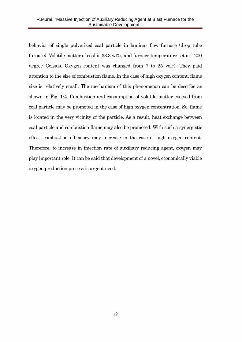
behavior of single pulverized coal particle in laminar flow furnace (drop tube
furnace). Volatile matter of coal is 33.3 wt%, and furnace temperature set at 1200
degree Celsius. Oxygen content was changed from 7 to 25 vol%. They paid
attention to the size of combustion flame. In the case of high oxygen content, flame
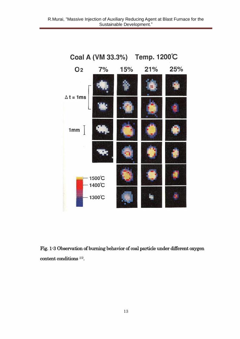
size is relatively small. The mechanism of this phenomenon can be describe as
shown in Fig. 1-4. Combustion and consumption of volatile matter evolved from
coal particle may be promoted in the case of high oxygen concentration. So, flame
is located in the very vicinity of the particle. As a result, heat exchange between
coal particle and combustion flame may also be promoted. With such a synergistic
effect, combustion efficiency may increase in the case of high oxygen content.
Therefore, to increase in injection rate of auxiliary reducing agent, oxygen may
play important role. It can be said that development of a novel, economically viable
oxygen production process is urgent need.
R.Murai, “Massive Injection of Auxiliary Reducing Agent at Blast Furnace for the
Sustainable Development.”
13
Fig. 1-3 Observation of burning behavior of coal particle under different oxygen
content conditions 23).
R.Murai, “Massive Injection of Auxiliary Reducing Agent at Blast Furnace for the
Sustainable Development.”
14
Fig. 1-4 Schematic representation of combustion mechanism of a single coal
particle 23).
1. 3. 2 Conventional oxygen production method
Currently, cryogenic air separation is most popular oxygen production
method. In this process, oxygen, nitrogen, and argon are separated by the
difference of their boiling points. Boiling points of oxygen, nitrogen, and argon are
90, 77, and 87 K respectively.
In typical cryogenic air separation, air is compressed from atmospheric
pressure to 450 kPa-G and is cooled to around 73 K by the adiabatic expansion.
Oxygen content of air is only a 20.9 vol%. It means that air with 5 times by volume
R.Murai, “Massive Injection of Auxiliary Reducing Agent at Blast Furnace for the
Sustainable Development.”
15
of oxygen must be compressed. Therefore, the problem of cryogenic air separation
is use of large amount of electrical power per unit oxygen. For example, specific
power consumption is around 0.36 kWh/Nm3-O2 at large scale cryogenic air
separation with a capacity of 60,000 Nm3/h class88).
Pressure Swing Adsorption (PSA) is another route to separate oxygen from
the air. Each gas may be adsorbed on the surface of solid (adsorbents) under the
higher pressure. When the pressure is decreased, gas may be released. Affinity
between each gas and adsorbents (or equilibrium adsorption quantity) is different.
By choosing adsorbent and pressure swing width appropriately, oxygen and
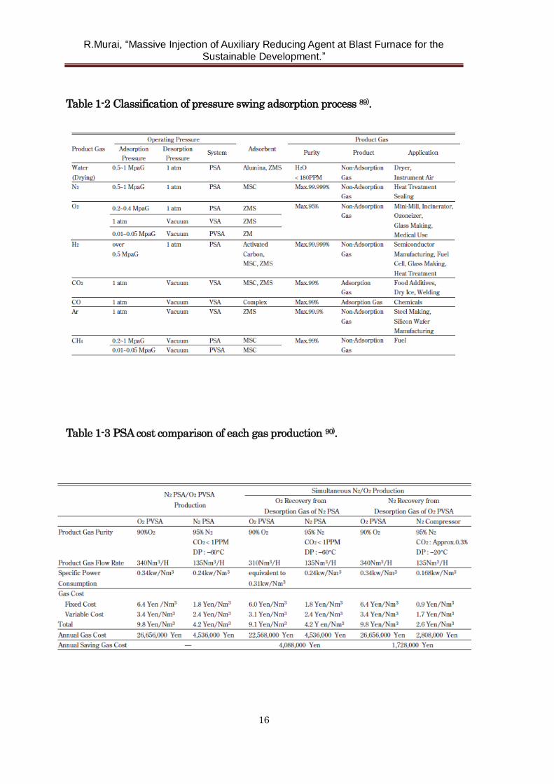
nitrogen can be separated from air. Table 1-2 shows classification of PSA process89).
Each process is sorted by the product gas, operating pressure, adsorbent, and
product gas. Regarding oxygen separation process, nitrogen gas is adsorbed and
released. So, purity is at most 95 vol% because argon gas in the air can not be
removed by this process. Moreover, nitrogen gas occupies majority of 79.1 vol% in
the air. So it is suggested that direct separation of oxygen may decrease cost of
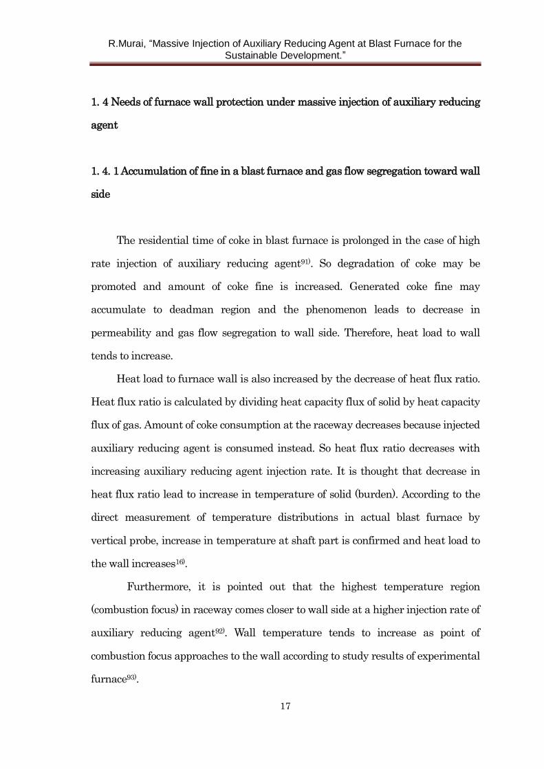
oxygen production. Table 1-3 shows PSA cost comparison of each gas production 90).
Specific power consumption of oxygen production is the range from 0.31 to 0.34
kWh/Nm3-O2.
R.Murai, “Massive Injection of Auxiliary Reducing Agent at Blast Furnace for the
Sustainable Development.”
16
Table 1-2 Classification of pressure swing adsorption process 89).
Table 1-3 PSA cost comparison of each gas production 90).
R.Murai, “Massive Injection of Auxiliary Reducing Agent at Blast Furnace for the
Sustainable Development.”
17
1. 4 Needs of furnace wall protection under massive injection of auxiliary reducing
agent
1. 4. 1 Accumulation of fine in a blast furnace and gas flow segregation toward wall
side
The residential time of coke in blast furnace is prolonged in the case of high
rate injection of auxiliary reducing agent91). So degradation of coke may be
promoted and amount of coke fine is increased. Generated coke fine may
accumulate to deadman region and the phenomenon leads to decrease in
permeability and gas flow segregation to wall side. Therefore, heat load to wall
tends to increase.
Heat load to furnace wall is also increased by the decrease of heat flux ratio.
Heat flux ratio is calculated by dividing heat capacity flux of solid by heat capacity
flux of gas. Amount of coke consumption at the raceway decreases because injected
auxiliary reducing agent is consumed instead. So heat flux ratio decreases with
increasing auxiliary reducing agent injection rate. It is thought that decrease in
heat flux ratio lead to increase in temperature of solid (burden). According to the
direct measurement of temperature distributions in actual blast furnace by
vertical probe, increase in temperature at shaft part is confirmed and heat load to
the wall increases16).
Furthermore, it is pointed out that the highest temperature region
(combustion focus) in raceway comes closer to wall side at a higher injection rate of
auxiliary reducing agent92). Wall temperature tends to increase as point of
combustion focus approaches to the wall according to study results of experimental
furnace93).
R.Murai, “Massive Injection of Auxiliary Reducing Agent at Blast Furnace for the
Sustainable Development.”
18
Formation of raceway shell (or bird’ s nest) is another noteworthy
phenomenon to describe increase in the heat load to wall27,94 ). Raceway shell is low
permeability layer formed at the end of raceway consisting of coke fine and low
viscosity ash which comes from solid auxiliary reducing agent. Once the raceway
shell is formed, gas permeability towards the inside of the furnace decreases. As a
result of this phenomenon, peripheral gas flow is intensified and heat load to wall
increases.
1. 4. 2 Overview of conventional cooling system of blast furnace
As mentioned in previous section, because of increase in heat load to wall,
furnace wall protection or enhancement of cooling capability is definitely
important. Therefore, cooling system of blast furnace is reviewed in this section.
Cooling plate system was widely used before 1969 in Japanese blast
furnaces95). The system is cooling method by inserting cooling plate into furnace
wall brick. Cooling capability is rather low and leakage of in-furnace gas is
occurred because thermal expansion ratio is different between cooling plate, wall
brick, and furnace steel shell.
To solve such problem, cooling stave (CS) was adopted95,96). Shaft part of the
blast furnace can be cooled from wide plane, so the cooling capability increases
considerably. To prolong CS campaign life, CS has been improved over the years.
For example, water feed system, arrangement of water cooling pipe, design of CS
body structure, and materials were improved97-99).
As for material, low chromium cast iron was used at first. Next, ductile cast
iron was used to prevent cracks. Thermal conductivity of copper is considerably
high compared with cast iron100,101). So excellent cooling capability can be expected
R.Murai, “Massive Injection of Auxiliary Reducing Agent at Blast Furnace for the
Sustainable Development.”
19
by use of copper CS. Development of cast copper CS is discussed in chapter 5.
1. 5 Purpose and contents of this thesis
The purpose of this thesis is to increase injection rate of auxiliary reducing
agent by solving above mentioned problems. It is considered that it makes
mitigation of carbon dioxide emissions from blast furnace possible because
hydrogen content of auxiliary reducing agent is rather high compared with coke.
The thesis includes seven chapters.
Chapter 1 presents a general introduction.
Chapter 2 describes the new injection lance for pulverized coal. To increase
the injection amount of pulverized coal, it is so important to improve a combustion
efficiency. Enhancement of particle dispersion is one of the measures to increase
combustion efficiency by accelerating oxygen-coal particle mixture in blowpipe to
tuyere region. To realize this, it is found that convergent – divergent injection lance
designed on the basis of the fluid dynamics has superior characteristics. Direct
observation results by offline apparatus, hot model experiments, and even in the
experiments at actual blast furnace prove that dispersion of pulverized coal
particles is enhanced and in-furnace permeability is improved at an actual blast
furnace. These results suggest that high combustion efficiency is achieved by using
developed injection lance.
Chapter 3 describes flow behavior of waste plastics in the blast furnace. Used
plastics injection into blast furnace is considered to contribute to construction of a
circulation type society and also mitigation of carbon dioxide emissions. However,
research on the flow behavior of plastic particles or unburnt char in the blast
furnace is few. Therefore, gasification behavior of plastic particles was determined
R.Murai, “Massive Injection of Auxiliary Reducing Agent at Blast Furnace for the
Sustainable Development.”
20
quantitatively by hot model experiments and thermogravimetry analysis in
condition similar to blast furnace at first. Then flow behavior of plastic particle and
unburnt char in a blast furnace was calculated by numerical simulation. As a
result of this research, desirable condition of plastic injection was clarified.
Chapter 4 describes novel production process of pure oxygen. Oxygen is
indispensable to promote combustion or gasification of auxiliary reducing agent. A
major problem of conventional oxygen production process such as cryogenic air
separation or nitrogen adsorbing type pressure swing adsorption is high cost of
production. Brownmillerite-type Ca2AlMnO5 exhibits remarkable oxygen
uptake/release capability, and therefore is a promising material for achieving
energy efficient air separation. The optimized conditions for glycine-nitrate-based
solution combustion synthesis of Ca2AlMnO5 is investigated.
Chapter 5 describes development of new cooling system. In the case of high
rate injection of auxiliary reducing agent, it is confirmed that heat load to furnace
wall increases. Therefore, enhancement of cooling capability of furnace wall is
necessary to maintain stable operation with high rate injection condition. Design
of cast copper cooling stave using finite element method is explained and its
application to actual blast furnace and change of in-furnace situation are
discussed.
Chapter 6 describes the concept of innovative ironmaking process. Intensive
injection of solid/gas reducing agent, oxygen blast, and recycle use of top gas are
integrated. As a result, it was evaluated that amount of carbon emission would be
reduced by eighty-six percent provided sequestration of carbon dioxide is
implemented.
Chapter 7 presents the general conclusions of this study.
R.Murai, “Massive Injection of Auxiliary Reducing Agent at Blast Furnace for the
Sustainable Development.”
21
References
1) Adoption of the Paris agreement, United Nations, 12 December 2015.
2) O. Edenhofer et al. : Climate change 2014 mitigation of climate change,
Summary for policymakers : Working group III contribution to the fifth
assessment report of the intergovernmental panel on climate change,
Intergovernmental panel on climate change, (2015),7
3) National Institute for Environmental Studies: The GHG emissions data of
Japan (1990-2014)
4) The Japan Iron and Steel Federation: Report of Commitment to a Low Carbon
Society in January 2015
5) S. Hayashi, G. Suzuki and T. Kobayashi: Tetsu-to-hagane, 49(1963), 655.
6) M. Kawabe, S. Wakuri, M. Baba, Y. Ishikawa and A. Hasegawa:
Tetsu-to-hagane,68(1982),2393.
7) Y. Otake, F. Nakamura : Tetsu-to-hagane, 58(1972),578.
8) M. Deguchi, S. Sasahara, J. Kasai, K. Tanaka and S. Tamura : Tetsu-to-hagane,
73(1987),1972.
9) S. Hayashi and T. Izawa : Journal of the Fuel Society of Japan, 46(1967),219.
10) S. Uno, N. Ishioka, S. Koizumi, M. Yagi and F. Ito : Tetsu-to-hagane,
66(1980),S97.
11) N. Takamatsu, K. Kurihara, A. Hatanaka, G. Saitoh and H. Kaku : Nippon
Steel Technical Report, 101(2012),79.
12) K. Morinaga, K. Tajima, Y. Jomoto, Y. Kanayama and H. Matsuoka : Journal of
the Fuel Society of Japan, 46(1967),211.
13) S. Yabe, I. Kurashige, T. Miyazaki, T. Iba, M. Kojima, Y. Shoji and Y. Kamei:
Proceedings of the Ironmaking conference, Toronto, Canada, (1981).
R.Murai, “Massive Injection of Auxiliary Reducing Agent at Blast Furnace for the
Sustainable Development.”
22
14) K. Morinaga, K. Tajima, K. Kusuno, Y. Kimoto, Y. Kanayama and H.
Matsuoka : Tetsu-to-hagane, 52(1966),107.
15) T. Miyazaki, Y. Shoji, Y. Kamei and T. Iba : Transactions ISIJ, 22(1982),207.
16) R. Ito, Y. Yoshida, K. Hoshino, F. Noma and T. Suzuki: Kobe Steel Engineering
reports, 50(2000), No.3, 6.
17) M. Naito, K. Takeda and Y. Matsui : Tetsu-to-hagane, 100(2014), 2.
18) H. Kugizaki, K. Oshima, I. Naruse and K. Otake: CAMP-ISIJ, 9(1996), 6.
19) H. Ueno, K. Yamaguchi and K. Tamura : ISIJ Int., 33(1993),640.
20) K. Ohtake: Proc. Of 3rd Int. Symp. on Coal Combustion, (1995), 195
21) R. H. Essenhigh, M. K. Misra and D. W. Shaw: Combustion and Flame,
77(1989), 3.
22) Y. Yamamoto, T. Ohe, I. Naruse and K. Ohtake: Trans. Jpn. Soc. Mech. Eng.,
ser. B, 60(1994), 649.
23) T. Ariyama, Y. Yamakawa and M. Sato : Tetsu-to-hagane, 81(1995), 703.
24) N. Kobayashi, T. Suzuki and T. Suwa : Inorganic Materials, 2(1995), No. 255,
115.
25) M. Saito, M. Sadakata, M. Sato and T. Sakai: Journal of Chemical Engineering
of Japan, 13(1987), 451.
26) T. Ariyama, M. Sato, Y. Yamakawa, Y. Yamada and M. Suzuki: Tetsu-to-hagane,
80(1994), 288.
27) T. Ariyama, M. Sato, R. Murai, K. Miyagawa, K. Nozawa and T. Kamijyo:
Tetsu-to-hagane, 81(1995), 1114.
28) H. Ueno, K. Yamaguchi and K. Tamura : Tetsu-to-hagane, 78(1992), 1206.
29) K. Yamaguchi, H. Ueno and K. Tamura : Tetsu-to-hagane, 78(1992), 1214.
30) M. Sato, R. Murai and T. Ariyama : Tetsu-to-hagane, 82(1996), 731.
31) M. Sato, R. Murai, T. Ariyama, A. Maki, A. Shimomura and K. Mori :
R.Murai, “Massive Injection of Auxiliary Reducing Agent at Blast Furnace for the
Sustainable Development.”
23
Tetsu-to-hagane, 84(1998), 37.
32) K. Tamura, H. Ueno, Y. Hayashi and T. Sato: Tetsu-to-hagane, 73(1987), S757.
33) J. Chung and N. Hur : ISIJ Int., 37(1997),119.
34) R. Murai, S. Kishimoto, H. Inoue, H. Mitsufuji, M. Sakurai and H. Wakai :
Proceedings of 1st ICSTI, ISIJ, Sendai, (1994), 272.
35) T. Yabata, K. Hoshino, Y. Yoshida, S. Ishiwaki and S. Kitayama:
Tetsu-to-hagane, 78(1992), T61.
36) T. Kamijyo, N. Takahashi, K. Hoshino, Y. Yoshida, R. Itoh, K. Shibata and Y.
Miyagawa: CAMP-ISIJ, 6(1993), 848.
37) M. Matsuura, T. Ariyama, M. Sato, K. Kimura, A. Shimomura and K. Mori:
CAMP-ISIJ, 9(1996), 635.
38) T. Sugiyama, S. Naito, S. Matsuzaki, T. Kumaoka and T. Nakayama:
CAMP-ISIJ, 7(1994), 46.
39) H. Haraguchi, T. Nishi, Y. Miura, Y. Ushikubo and T. Noda: Tetsu-to-hagane,
70(1984), 2216.
40) K. Yamaguchi, H. Hino, S. Matsunaga, K. Kakiuchi and S. Amano: ISIJ Int.,
35(1995),148.
41) H. Yamaoka: Tetsu-to-hagane, 72(1986), 403.
42) K. Shibata, M. Shimizu, S. Inaba, R. Takahashi and J. Yagi: ISIJ Int.,
31(1991),434.
43) R. Murai, A. Murao, K. Goto, M. Sato and T. Ariyama: Tetsu-to-hagane,
88(2002), 249.
44) M. Sato, K. Fukada, T. Ariyama, S. Itagaki and R. Murai: Tetsu-to-hagane,
87(2001), 365.
45) M. Kuwabara, Y. Hsieh, K. Osobo and I. Muchi: Aust. Inst. Min. Metall. Symp.
Ser. No. 26,(1981), 7.
R.Murai, “Massive Injection of Auxiliary Reducing Agent at Blast Furnace for the
Sustainable Development.”
24
46) J. He, M. Kuwabara and I. Muchi: Tetsu-to-hagane, 72(1986), 35.
47) A. S. Jamaluddin, T. F. Wall and J. S. Truelove : Ironmaking Steelmaking,
13(1986), 91.
48) H. Nogami, T. Miura and T. Furukawa : Tetsu-to-hagane, 78(1992), 1222.
49) K. Takeda and F. C. Lockwood: ISIJ Int., 37(1997),432.
50) X. Xiao, K. Nozawa, S. Sasahara, M. Shimizu and S. Inaba : Tetsu-to-hagane,
78(1992), 1230.
51) S. Nagami, T. Murai, Y. Shimoda, S. Komatsu and T. Inada: CAMP-ISIJ,
6(1993), 26.
52) J. Z. Chen, H. Nogami, T. Ariyama, R. Takahashi and J. Yagi : Advances in
Multiphase Flow, Elsevier Science (1995), 619.
53) K. Takeda and F. C. Lockwood: Tetsu-to-hagane, 82(1996), 492.
54) K. Shibata, R. Takahashi, M. Shimizu and J. Yagi: Tetsu-to-hagane, 75(1991),
1267.
55) H. Nogami, P. R. Austin and J. Yagi: CAMP-ISIJ, 8(1995), 30.
56) A. Maki, A. Sakai, N. Takagaki, K. Mori, T. Ariyama, M. Sato and R. Murai:
ISIJ Int., 36(1996),650.
57) K. Kakiuchi, S. Matsunaga, A. Sakamoto, H. Matsuoka, H. Ueno and K.
Yamaguchi: CAMP-ISIJ, 7(1994), 126.
58) M. Atsushi, H. Nakaya, S. Kitano, J. Yamagata, K. Shibata, T. Goto, R. Ono
and T. Yabata: CAMP-ISIJ, 8(1995), 321.
59) R. Maldonado, R. C. Mills, B. K. Hartley and N. J. Busby : Proc. 1st Int. Cong.
on Science and Technology of Ironmaking, Sendai, ISIJ, (1994), 535.
60) The Japan Containers And Packaging Recycling Association: Report on
Environmental Impact Regarding Recycling of plastics (2007), 20.
61) Plastic Waste Management Institute JAPAN: An Introduction to Plastic
R.Murai, “Massive Injection of Auxiliary Reducing Agent at Blast Furnace for the
Sustainable Development.”
25
Recycling (2013), 5.
62) J. Janz and W. Weiss: Proc. 3rd European Ironmaking Congress, Gent, Belgium,
(1996), 114.
63) A. G. Buekens, B. D. Caevel and M. D. Vos: Proc. 1st Inter. Symp. on Feedstock
Recycling of Plastics (1999), Sendai, PE-1, 91.
64) K. Nemoto, M. Iemoto and S. Sekine: Zairyo-to-Kankyo,48(1999),61.
65) Y. Yoshida, K. Nozawa, Y. Matsui, T. Funabiki and T. Mine: Kobe steel giho,
51(2002), 58.
66) T. Panagiotou and Y. A. Levendis: Combustion and Flame, 99(1994), 53.
67) T. Panagiotou and Y. A. Levendis: Combust. Sci. and Tech., 103(1994), 63.
68) T. Panagiotou and Y. A. Levendis: Combust. Sci. and Tech., 112(1996), 117.
69) T. Panagiotou and Y. A. Levendis: Proc. Twenty-Sixth on Combustion/The
combustion Institute (1996), 2421.
70) K. Yamaguchi, T. Deno and N. Konno: Tetsu-to-hagane, 83(1997), 545.
71) M. Asanuma, T. Ariyama, M. Sato, R. Murai, T. Nonaka, I. Okochi, H. Tsukiji
and K. Nemoto: ISIJ Int., 40(2000),244.
72) R. Jeschar and G. Dombrowski: Stahl und Eisen, 116(1996), No. 8, 81.
73) H. B. Lungen: Proc. ENCOSTEEL (1997), 77.
74) M. Asanuma, M. Kajioka and H. Tsuruta: Journal of the Japan Institute of
Energy, 91(2012),127.
75) M. Asanuma, M. Kajioka, M. Kuwabara, Y. Fukumoto and K. Terada: JFE giho,
22(2008), 67.
76) S. Yaroshevskii: Pig Iron Smelting Using Pulverized Coal injection Metallurgia,
Moscow, (1988), 176.
77) J. A. Castro, H. Nogami and J. Yagi : CAMP-ISIJ, 13(2000), 137.
78) J. M. Steiler: ICSTI / Ironmaking Conference Proceedings Vol. 57, ISS,
R.Murai, “Massive Injection of Auxiliary Reducing Agent at Blast Furnace for the
Sustainable Development.”
26
Warrendale, PA, (1988), 343.
79) K. Yamamoto, Y. Kashihara and H. Tsukiji : JFE Technical Report, 22(2008),
55.
80) A. Majeski, A. Runstedtler, J. D’alessio and N. Macfadyen : ISIJ Int.,
55(2015),1377.
81) E. A. Mousa, A. Babich and D. Senk: ISIJ Int., 53(2013),1372.
82) K. Kato, S. Hashimoto, K. Mori and Z. Ayuha: Tetsu-to-hagane, 48(1962), 365.
83) T. H. Burgler, G. Brunnbauer, A. Ferstl: 3rd International Conference on
Science and Technology of Ironmaking, Steel Institute VDEH, Dusseldorf, (2003),
157.
84) A. Babich, S. Yaroshevskii, A. Formoso, A. Cores, L. Garcia and V. Nozdrachev:
ISIJ Int., 39(1999),229.
85) J. A. Castro, H. Nogami and J. Yagi: ISIJ Int., 42(2002),1203.
86) A. Murao, Y. Kashihara, K. Takahashi, N. Oyama, H. Matsuno and M. Sato:
Tetsu-to-hagane, 101(2015), 653.
87) P. Hellberg, T. L. Jonsson, P. G. Jonsson and D. Y. Sheng: Metallurgical and
Process Industries SINTEF/ NTNU, Trondheim, Norway, (2005),1.
88) Taiyo Nissan Giho, 24(2005), 64.
89) K. Haruna: J. Vac. Soc. Jpn.: 43(2000), No.2, 1088.
90) K. Haruna, M. Miyake and H. Sasano: Sumitomo Kagaku, (2005), No.2, 59.
91) T. Ariyama, M. Sato, T. Sato, S. Watakabe and R. Murai: Tetsu-to-hagane,
92(2006), 114.
92) K. Shibata, N. Nozawa, M. Shimizu, R. Ono, T. Okuda, R. Ito and K. Hanao:
CAMP-ISIJ, 6(1993), 112.
93) K. Miyagawa, K. Nozawa, Y. Kamijo, M. Sato, Y. Yamakawa and T. Ariyama:
CAMP-ISIJ, 7(1994), 128.
R.Murai, “Massive Injection of Auxiliary Reducing Agent at Blast Furnace for the
Sustainable Development.”
27
94) Y. Shen, T. Shiozawa, P. Austin and A. Yu: Minerals Engineering, 63(2014), 91.
95) H. Kanoshima : Survey Reports on the Systemization of Technologies, 15(2010),
81.
96) F. Ito, A. Hanafusa, Y. Takei, T. Mitsuyasu and Y. Mizuno: Tetsu-to-hagane,
78(1992), 1179.
97) K. Kawaoka, K. Anan, A. Tsuda, K. Kakiuchi, Y. Matsuoka, H. Takeshita, K.
Nishioka and H. Takasaki: Shinnittetsu Giho, 384(2006), 115.
98) W. Lijiun, Z. Weiguo, C. Huier, S. Yunlong and L. Xiaojing: Applied
Mathematical Modelling., 31(2007),1249.
99) M. Maito, K. Takeda and Y. Matsui: ISIJ Int., 55(2015),7.
100) H. Tsukiji, K. Ishii, K. Kimura, M. Sakurai, A, Sakai, M. Sato and T. Ariyama:
CAMP-ISIJ, 14(2001), 758.
101) M. Gocho, K. Kimura, H. Nakamura, A. Sakai, T. Araki and M. Matsuura:
CAMP-ISIJ, 12(1999), 708.
R.Murai, “Massive Injection of Auxiliary Reducing Agent at Blast Furnace for the
Sustainable Development.”
28
Chapter 2 Enhancement of combustion efficiency to increase
injection amount of auxiliary reducing agents to blast
furnace
2. 1 Introduction
Pulverized coal injection into blast furnace as an alternative reducing agent
has spread widely resently1,2), because it may reduce coke consumption and
decrease carbon dioxide emissions by increase in hydrogen reduction3,4).
Several studies regarding effect of coke fine generation and accumulation due
to the high rate injection of pulverized coal on the permeability of blast furnace
have been reported5-8). To inject large amount of pulverized coal into the blast
furnace stably, enhancement of combustion efficiency is important. For example,
Sato et al. reported that improvement of combustion efficiency of pulverized coal
led to decrease in generation rate of coke fine in the raceway region and
improvement of permeability of the blast furnace9).
To improve combustion efficiency of pulverized coal, several kinds of injection
lance have been proposed. They included double lance arrangement10), eccentric
double lance arrangement11), high turbulence lance with diagonal edge12), swirl
burner13) for example. Purpose of these injection lance arrangements is
enhancement of particle dispersion. In the blowpipe or tuyere region, the
momentum of blast is predominant. So dispersion of coal particles in orthogonal
direction to the flow is limited. Multi point injection or momentum transportation
by turbulent flow to the orthogonal direction is considered to be effective to the
particle dispersion. Oxy-coal lance, that is pulverized coal and pure oxygen are
injected simultaneously using co-axial lance has been proposed13,14). Concentration
R.Murai, “Massive Injection of Auxiliary Reducing Agent at Blast Furnace for the
Sustainable Development.”
29
of oxygen in coal combustion region can be increased directly by using this kind of
lance. Therefore, combustion efficiency of pulverized coal is improved greatly. To
apply the oxy-coal lance, however, significant amount of pure oxygen is needed.
Therefore, there must be some restriction or need for a large amount of investment
cost.
In this chapter, convergent - divergent injection lance is proposed. Pulverized
coal particles are able to be diffused well in the blow pipe to tuyere region by the
combination of effective utilization of particle inertia and control of flow separation
phenomenon in the boundary layer. This type of lance can enhance the combustion
efficiency by the relatively simple method and it may be combined with existing
injection lance arrangement easily.
The Author, at first, designed the lance tip configuration of convergent -
divergent injection lance based on the theory of the boundary layer. Then, effect of
the lance tip configuration on the particle dispersibility was verified by the direct
observation using offline apparatus in the atmospheric condition. Hot model
experimental results showed advantages of the lance tip configuration including
particle dispersibility in the blowpipe and coke replacement ratio of pulverized
coal.
As the convergent - divergent injection lance proved to be valid judging from
offline and hot model experiments, the lances were used at actual blast furnace. It
was confirmed that permeability of the furnace improved by the use of the lances.
The reason of this phenomenon might be decrease in the amount of accumulation
of coke fine in the lower part of blast furnace. It was considered that enhancement
of coal particle dispersion by the use of convergent – divergent injection lance made
combustion efficiency of pulverized coal higher and coke degradation was
restrained by enhancement of combustion efficiency of pulverized coal.
R.Murai, “Massive Injection of Auxiliary Reducing Agent at Blast Furnace for the
Sustainable Development.”
30
2.2 Concept of particle dispersion enhancement by convergent – divergent lance
2.2.1 Flow separation in divergent lance
To enhance combustion efficiency of pulverized coal, it has been pointed out
that dispersion of coal particle is important. It is thought that flow control by
divergent lance is effective.
Divergent lance, where the stream cross section increases from inlet to outlet,
can be generate diffusion flow. Therefore, coal particles carried by the gas can also
be dispersed. However, when the divergence angle becomes larger, diffusion is
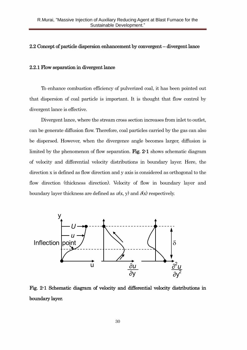
limited by the phenomenon of flow separation. Fig. 2-1 shows schematic diagram
of velocity and differential velocity distributions in boundary layer. Here, the
direction x is defined as flow direction and y axis is considered as orthogonal to the
flow direction (thickness direction). Velocity of flow in boundary layer and
boundary layer thickness are defined as u(x, y) and (x) respectively.
Fig. 2-1 Schematic diagram of velocity and differential velocity distributions in
boundary layer.
R.Murai, “Massive Injection of Auxiliary Reducing Agent at Blast Furnace for the
Sustainable Development.”
31
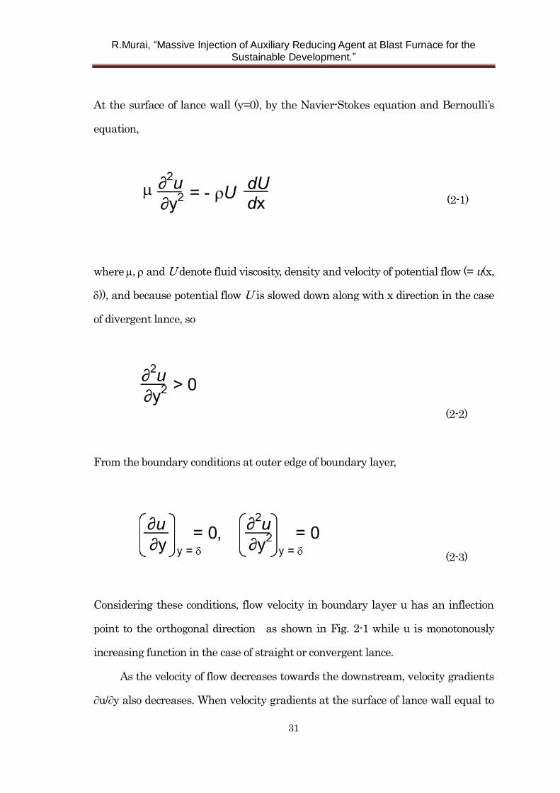
At the surface of lance wall (y=0), by the Navier-Stokes equation and Bernoulli’s
equation,
(2-1)
where , and U denote fluid viscosity, density and velocity of potential flow (= u(x,
)), and because potential flow U is slowed down along with x direction in the case
of divergent lance, so
(2-2)
From the boundary conditions at outer edge of boundary layer,
(2-3)
Considering these conditions, flow velocity in boundary layer u has an inflection
point to the orthogonal direction as shown in Fig. 2-1 while u is monotonously
increasing function in the case of straight or convergent lance.
As the velocity of flow decreases towards the downstream, velocity gradients
∂u/∂y also decreases. When velocity gradients at the surface of lance wall equal to
R.Murai, “Massive Injection of Auxiliary Reducing Agent at Blast Furnace for the
Sustainable Development.”
32
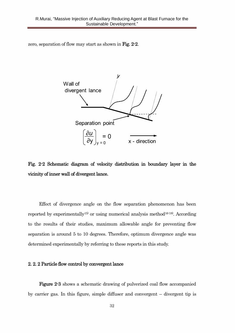
zero, separation of flow may start as shown in Fig. 2-2.
Fig. 2-2 Schematic diagram of velocity distribution in boundary layer in the
vicinity of inner wall of divergent lance.
Effect of divergence angle on the flow separation phenomenon has been
reported by experimentally15) or using numerical analysis method16-18). According
to the results of their studies, maximum allowable angle for preventing flow
separation is around 5 to 10 degrees. Therefore, optimum divergence angle was
determined experimentally by referring to these reports in this study.
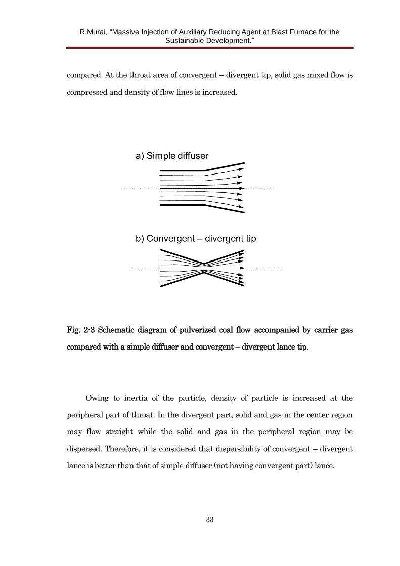
2. 2. 2 Particle flow control by convergent lance
Figure 2-3 shows a schematic drawing of pulverized coal flow accompanied
by carrier gas. In this figure, simple diffuser and convergent – divergent tip is
R.Murai, “Massive Injection of Auxiliary Reducing Agent at Blast Furnace for the
Sustainable Development.”
33
compared. At the throat area of convergent – divergent tip, solid gas mixed flow is
compressed and density of flow lines is increased.
Fig. 2-3 Schematic diagram of pulverized coal flow accompanied by carrier gas
compared with a simple diffuser and convergent – divergent lance tip.
Owing to inertia of the particle, density of particle is increased at the
peripheral part of throat. In the divergent part, solid and gas in the center region
may flow straight while the solid and gas in the peripheral region may be
dispersed. Therefore, it is considered that dispersibility of convergent – divergent
lance is better than that of simple diffuser (not having convergent part) lance.
R.Murai, “Massive Injection of Auxiliary Reducing Agent at Blast Furnace for the
Sustainable Development.”
34
2. 3 Direct observation of flow behavior of pulverized coal particle
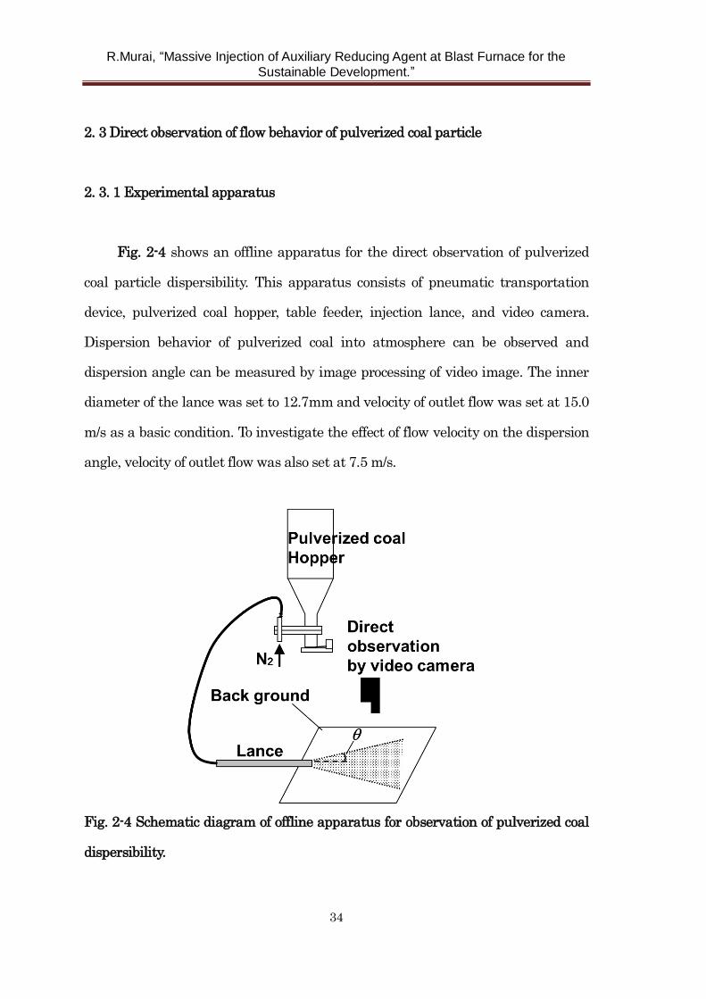
2. 3. 1 Experimental apparatus
Fig. 2-4 shows an offline apparatus for the direct observation of pulverized
coal particle dispersibility. This apparatus consists of pneumatic transportation
device, pulverized coal hopper, table feeder, injection lance, and video camera.
Dispersion behavior of pulverized coal into atmosphere can be observed and
dispersion angle can be measured by image processing of video image. The inner
diameter of the lance was set to 12.7mm and velocity of outlet flow was set at 15.0
m/s as a basic condition. To investigate the effect of flow velocity on the dispersion
angle, velocity of outlet flow was also set at 7.5 m/s.
Fig. 2-4 Schematic diagram of offline apparatus for observation of pulverized coal
dispersibility.
R.Murai, “Massive Injection of Auxiliary Reducing Agent at Blast Furnace for the
Sustainable Development.”
35
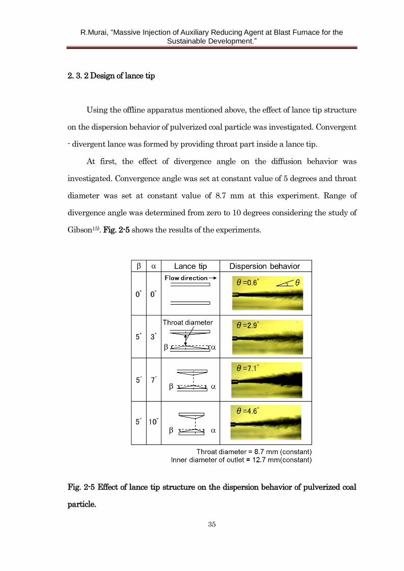
2. 3. 2 Design of lance tip
Using the offline apparatus mentioned above, the effect of lance tip structure
on the dispersion behavior of pulverized coal particle was investigated. Convergent
- divergent lance was formed by providing throat part inside a lance tip.
At first, the effect of divergence angle on the diffusion behavior was
investigated. Convergence angle was set at constant value of 5 degrees and throat
diameter was set at constant value of 8.7 mm at this experiment. Range of
divergence angle was determined from zero to 10 degrees considering the study of
Gibson15). Fig. 2-5 shows the results of the experiments.
Fig. 2-5 Effect of lance tip structure on the dispersion behavior of pulverized coal
particle.
R.Murai, “Massive Injection of Auxiliary Reducing Agent at Blast Furnace for the
Sustainable Development.”
36
As shown in Fig. 2-5, image of dispersion area of pulverized coal is taken by video
camera as black pixels. By the image processing, dispersion angle is measured.
In the case that divergence angle is 3 degrees, observed dispersion angle is 2.9
degrees. And in the case that is 7 degrees, is 7.1 degrees. In these cases, values
of substantially coincide with . It means that separation of flow in the divergent
lance can be avoided successfully because values of are relatively small. However,
when is increased further, can not be followed ( is only 4.6 degrees to 10
degrees of ). It suggests that separation of flow occurs in the higher divergence
angle over 7 degrees. Considering these experimental results, optimum divergence
angle was determined at 7 degrees.
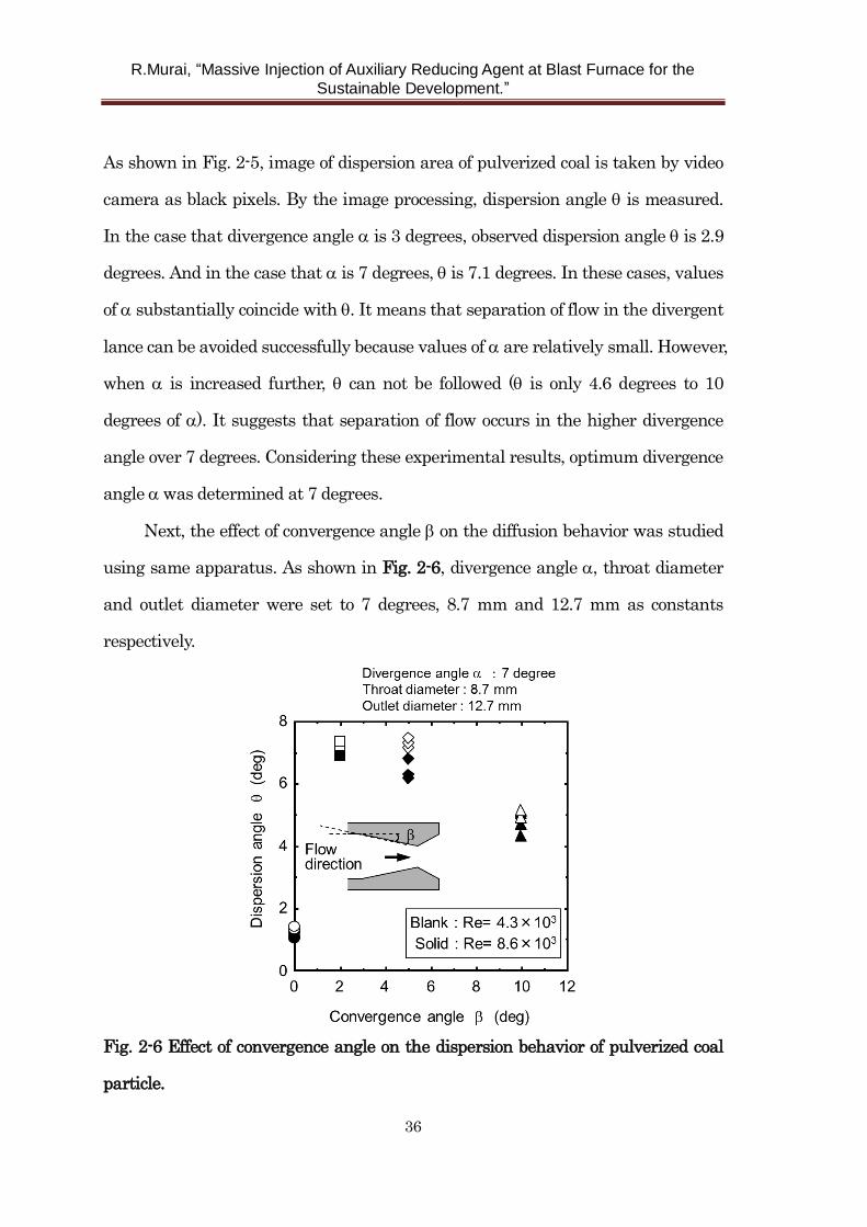
Next, the effect of convergence angle on the diffusion behavior was studied
using same apparatus. As shown in Fig. 2-6, divergence angle , throat diameter
and outlet diameter were set to 7 degrees, 8.7 mm and 12.7 mm as constants
respectively.
Fig. 2-6 Effect of convergence angle on the dispersion behavior of pulverized coal
particle.
R.Murai, “Massive Injection of Auxiliary Reducing Agent at Blast Furnace for the
Sustainable Development.”
37
In Fig. 2-6, data of straight tip ( = =0 degree and outlet diameter = throat
diameter = 12.7 mm) were also shown for comparison. To clarify the effect of flow
rate (Reynolds number: Re), flow rates of 7.5 m/s and 15.0 m/s were chosen and
they corresponded to Reynolds numbers of 4.3×10³ and 8.6×10³ respectively.
Dispersibility could be enhanced even in relatively small angles of 2 to 5
degrees compared with straight tip. However, when is increased further, shows
a decrease tendency. It suggests that scatter of particles by colliding with an inner
wall of lance tip affects dispersibility of convergent – divergent lance. It seems that
effect of Reynolds number is relatively small. If the is small, it takes longer
length to form throat shape. So it is decided that optimum value is 5 degrees.
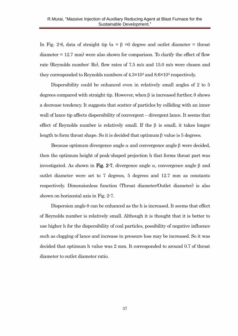
Because optimum divergence angle and convergence angle were decided,
then the optimum height of peak-shaped projection h that forms throat part was
investigated. As shown in Fig. 2-7, divergence angle , convergence angle and
outlet diameter were set to 7 degrees, 5 degrees and 12.7 mm as constants
respectively. Dimensionless function (Throat diameter/Outlet diameter) is also
shown on horizontal axis in Fig. 2-7.
Dispersion angle can be enhanced as the h is increased. It seems that effect
of Reynolds number is relatively small. Although it is thought that it is better to
use higher h for the dispersibility of coal particles, possibility of negative influence
such as clogging of lance and increase in pressure loss may be increased. So it was
decided that optimum h value was 2 mm. It corresponded to around 0.7 of throat
diameter to outlet diameter ratio.
R.Murai, “Massive Injection of Auxiliary Reducing Agent at Blast Furnace for the
Sustainable Development.”
38
Fig. 2-7 Effect of height of peak – shaped projection on the dispersion behavior of
pulverized coal particle.
2. 4 Study on dispersibility and combustion behavior of pulverized coal by hot
model experiment
2. 4. 1 Outline of hot model experimental furnace
In the previous section, pulverized coal was blown to air atmosphere.
Considering condition of pulverized coal injection at actual blast furnace, study on
dispersion behavior in hot blast is required.
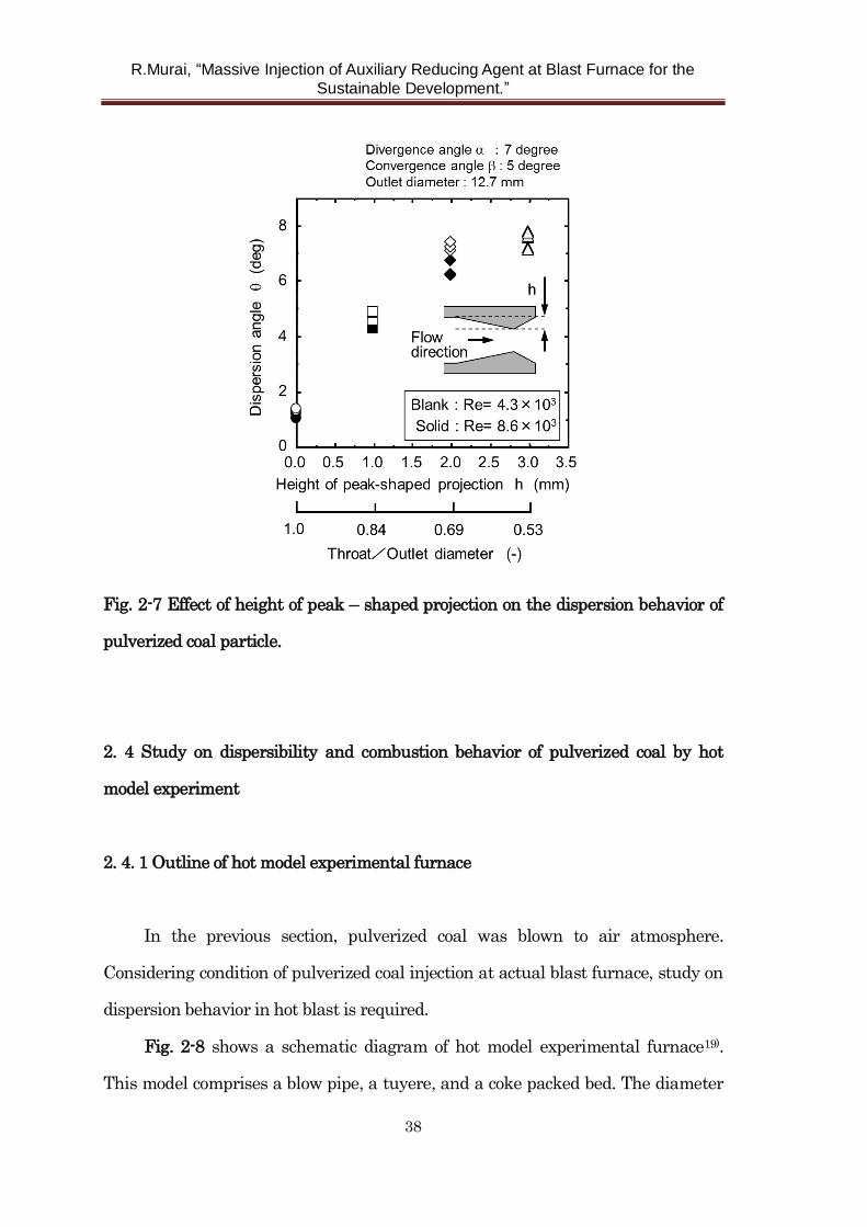
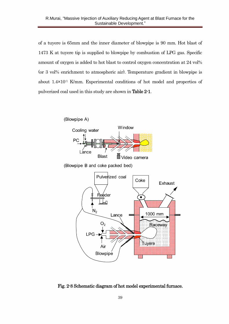
Fig. 2-8 shows a schematic diagram of hot model experimental furnace19).
This model comprises a blow pipe, a tuyere, and a coke packed bed. The diameter
R.Murai, “Massive Injection of Auxiliary Reducing Agent at Blast Furnace for the
Sustainable Development.”
39
of a tuyere is 65mm and the inner diameter of blowpipe is 90 mm. Hot blast of
1473 K at tuyere tip is supplied to blowpipe by combustion of LPG gas. Specific
amount of oxygen is added to hot blast to control oxygen concentration at 24 vol%
(or 3 vol% enrichment to atmospheric air). Temperature gradient in blowpipe is
about 1.4×10⁻¹ K/mm. Experimental conditions of hot model and properties of
pulverized coal used in this study are shown in Table 2-1.
Fig. 2-8 Schematic diagram of hot model experimental furnace.
R.Murai, “Massive Injection of Auxiliary Reducing Agent at Blast Furnace for the
Sustainable Development.”
40
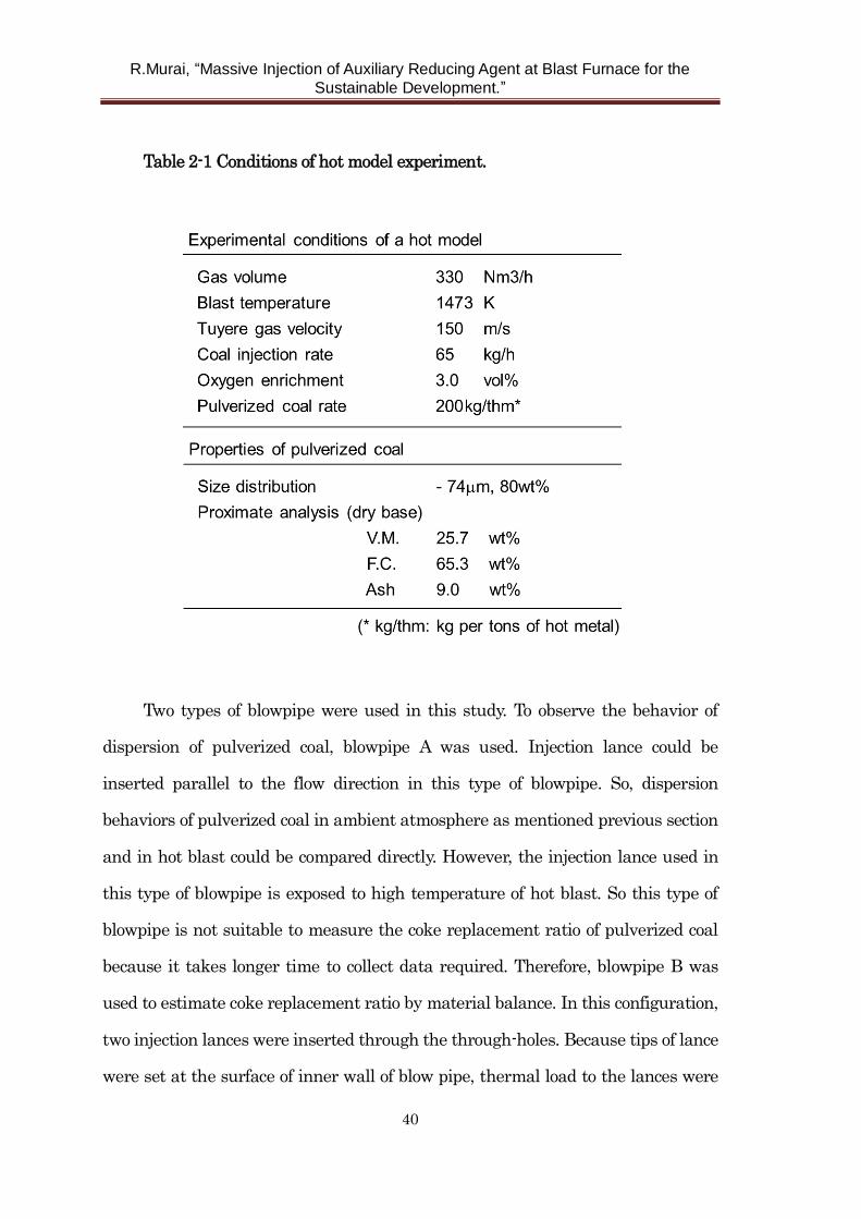
Table 2-1 Conditions of hot model experiment.
Two types of blowpipe were used in this study. To observe the behavior of
dispersion of pulverized coal, blowpipe A was used. Injection lance could be
inserted parallel to the flow direction in this type of blowpipe. So, dispersion
behaviors of pulverized coal in ambient atmosphere as mentioned previous section
and in hot blast could be compared directly. However, the injection lance used in
this type of blowpipe is exposed to high temperature of hot blast. So this type of
blowpipe is not suitable to measure the coke replacement ratio of pulverized coal
because it takes longer time to collect data required. Therefore, blowpipe B was
used to estimate coke replacement ratio by material balance. In this configuration,
two injection lances were inserted through the through-holes. Because tips of lance
were set at the surface of inner wall of blow pipe, thermal load to the lances were
R.Murai, “Massive Injection of Auxiliary Reducing Agent at Blast Furnace for the
Sustainable Development.”
41
reduced compared with blowpipe A. Stable and longer injection of pulverized coal
was realized using blowpipe B.
2. 4. 2 Evaluation of particle dispersion
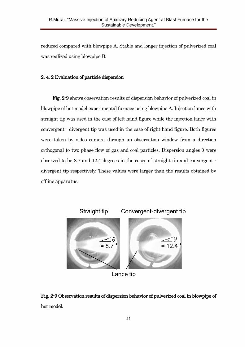
Fig. 2-9 shows observation results of dispersion behavior of pulverized coal in
blowpipe of hot model experimental furnace using blowpipe A. Injection lance with
straight tip was used in the case of left hand figure while the injection lance with
convergent - divergent tip was used in the case of right hand figure. Both figures
were taken by video camera through an observation window from a direction
orthogonal to two phase flow of gas and coal particles. Dispersion angles were
observed to be 8.7 and 12.4 degrees in the cases of straight tip and convergent -
divergent tip respectively. These values were larger than the results obtained by
offline apparatus.
Fig. 2-9 Observation results of dispersion behavior of pulverized coal in blowpipe of
hot model.
R.Murai, “Massive Injection of Auxiliary Reducing Agent at Blast Furnace for the
Sustainable Development.”
42
These results suggest that turbulence towards downstream of lance tip generated
by the lance itself has a significant influence on the particle dispersion12). However,
it is to be emphasized that the dispersion angle of convergent – divergent tip is
larger than that of straight tip as in the case of offline experiments. It is confirmed
that flow control without flow separation by convergent – divergent lance
enhances the dispersibility of pulverized coal particles.
2. 4. 3 Effect of particle dispersibility on coke replacement ratio of pulverized coal
in hot model experiment
Using blowpipe B, hot model experiments were conducted to determine the
coke replacement ratio of pulverized coal. Because multiple lances can be used in
this model, the eccentric double lance arrangement was adopted in this study 11).
Exchanging only lance tips, two kinds of experiments using straight lance tip and
convergent – divergent lance tip could be conducted. The results of combustion
experiments were compared.
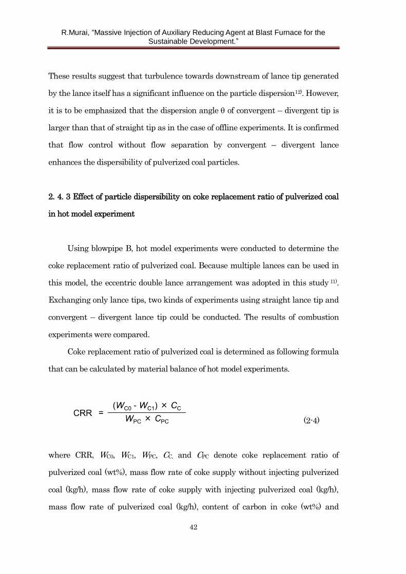
Coke replacement ratio of pulverized coal is determined as following formula
that can be calculated by material balance of hot model experiments.
(2-4)
where CRR, WC0, WC1, WPC, CC, and CPC denote coke replacement ratio of
pulverized coal (wt%), mass flow rate of coke supply without injecting pulverized
coal (kg/h), mass flow rate of coke supply with injecting pulverized coal (kg/h),
mass flow rate of pulverized coal (kg/h), content of carbon in coke (wt%) and
R.Murai, “Massive Injection of Auxiliary Reducing Agent at Blast Furnace for the
Sustainable Development.”
43
content of carbon in pulverized coal (wt%) respectively.
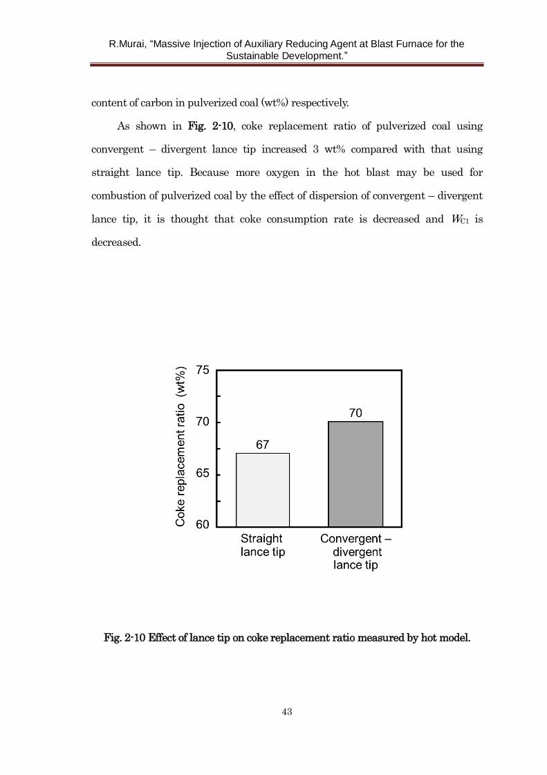
As shown in Fig. 2-10, coke replacement ratio of pulverized coal using
convergent – divergent lance tip increased 3 wt% compared with that using
straight lance tip. Because more oxygen in the hot blast may be used for
combustion of pulverized coal by the effect of dispersion of convergent – divergent
lance tip, it is thought that coke consumption rate is decreased and WC1 is
decreased.
Fig. 2-10 Effect of lance tip on coke replacement ratio measured by hot model.
R.Murai, “Massive Injection of Auxiliary Reducing Agent at Blast Furnace for the
Sustainable Development.”
44
2. 5 Application of convergent – divergent lance to actual blast furnace
2. 5. 1 Evaluation of particle dispersibility at actual blast furnace
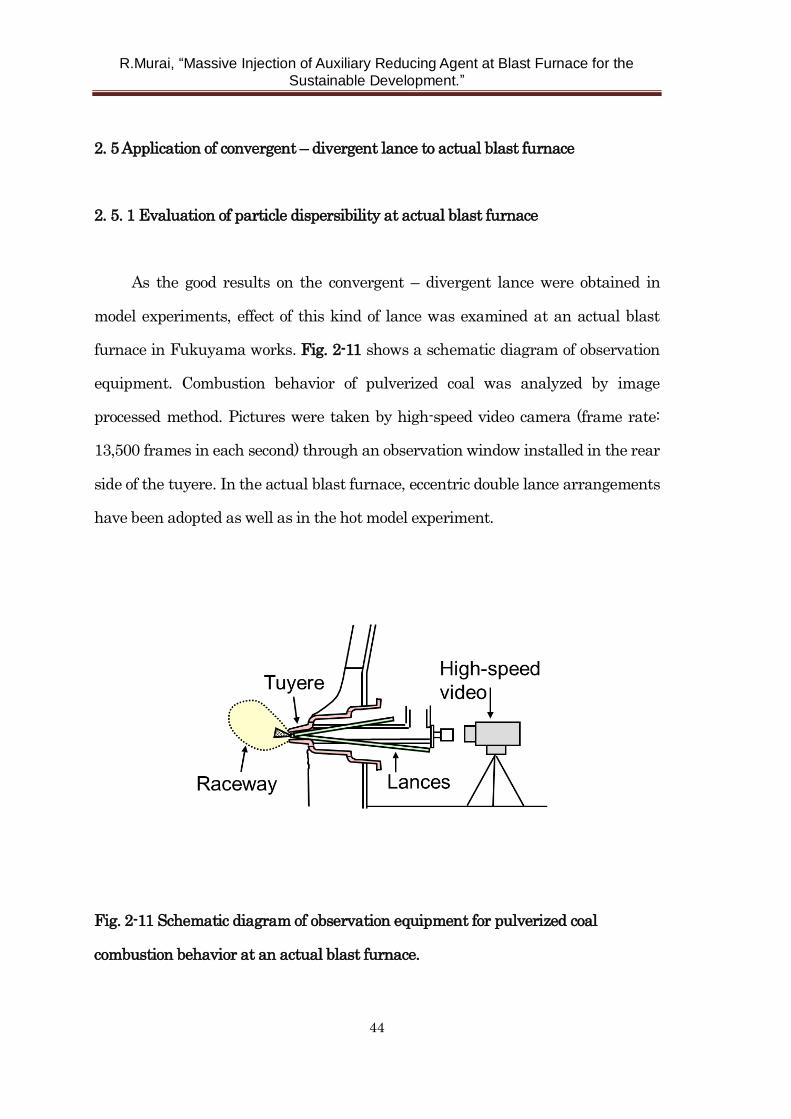
As the good results on the convergent – divergent lance were obtained in
model experiments, effect of this kind of lance was examined at an actual blast
furnace in Fukuyama works. Fig. 2-11 shows a schematic diagram of observation
equipment. Combustion behavior of pulverized coal was analyzed by image
processed method. Pictures were taken by high-speed video camera (frame rate:
13,500 frames in each second) through an observation window installed in the rear
side of the tuyere. In the actual blast furnace, eccentric double lance arrangements
have been adopted as well as in the hot model experiment.
Fig. 2-11 Schematic diagram of observation equipment for pulverized coal
combustion behavior at an actual blast furnace.
R.Murai, “Massive Injection of Auxiliary Reducing Agent at Blast Furnace for the
Sustainable Development.”
45
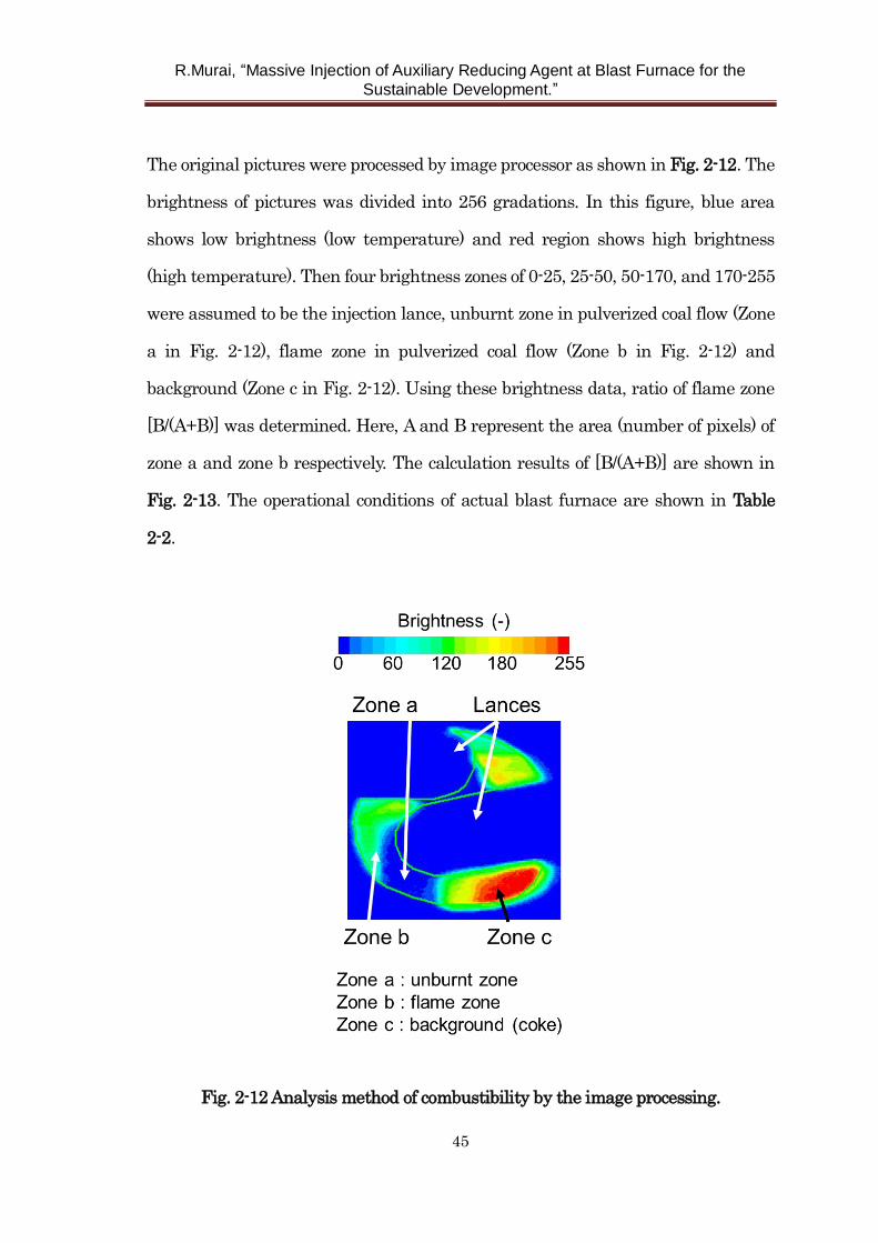
The original pictures were processed by image processor as shown in Fig. 2-12. The
brightness of pictures was divided into 256 gradations. In this figure, blue area
shows low brightness (low temperature) and red region shows high brightness
(high temperature). Then four brightness zones of 0-25, 25-50, 50-170, and 170-255
were assumed to be the injection lance, unburnt zone in pulverized coal flow (Zone
a in Fig. 2-12), flame zone in pulverized coal flow (Zone b in Fig. 2-12) and
background (Zone c in Fig. 2-12). Using these brightness data, ratio of flame zone
[B/(A+B)] was determined. Here, A and B represent the area (number of pixels) of
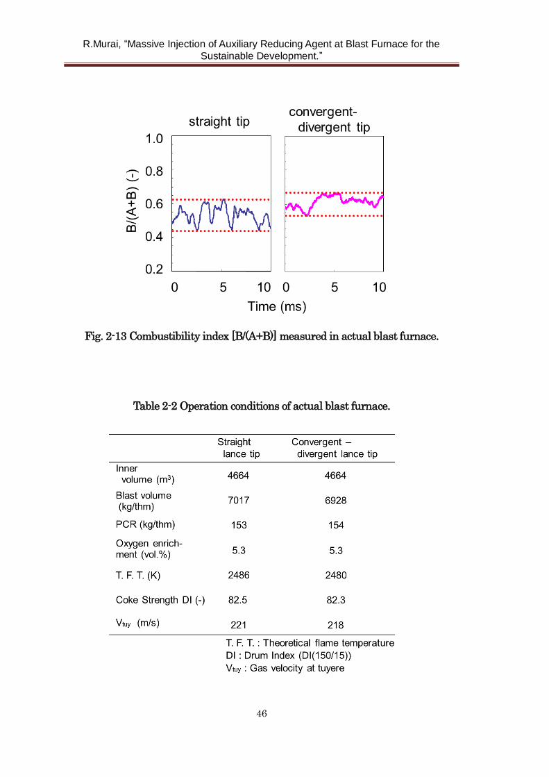
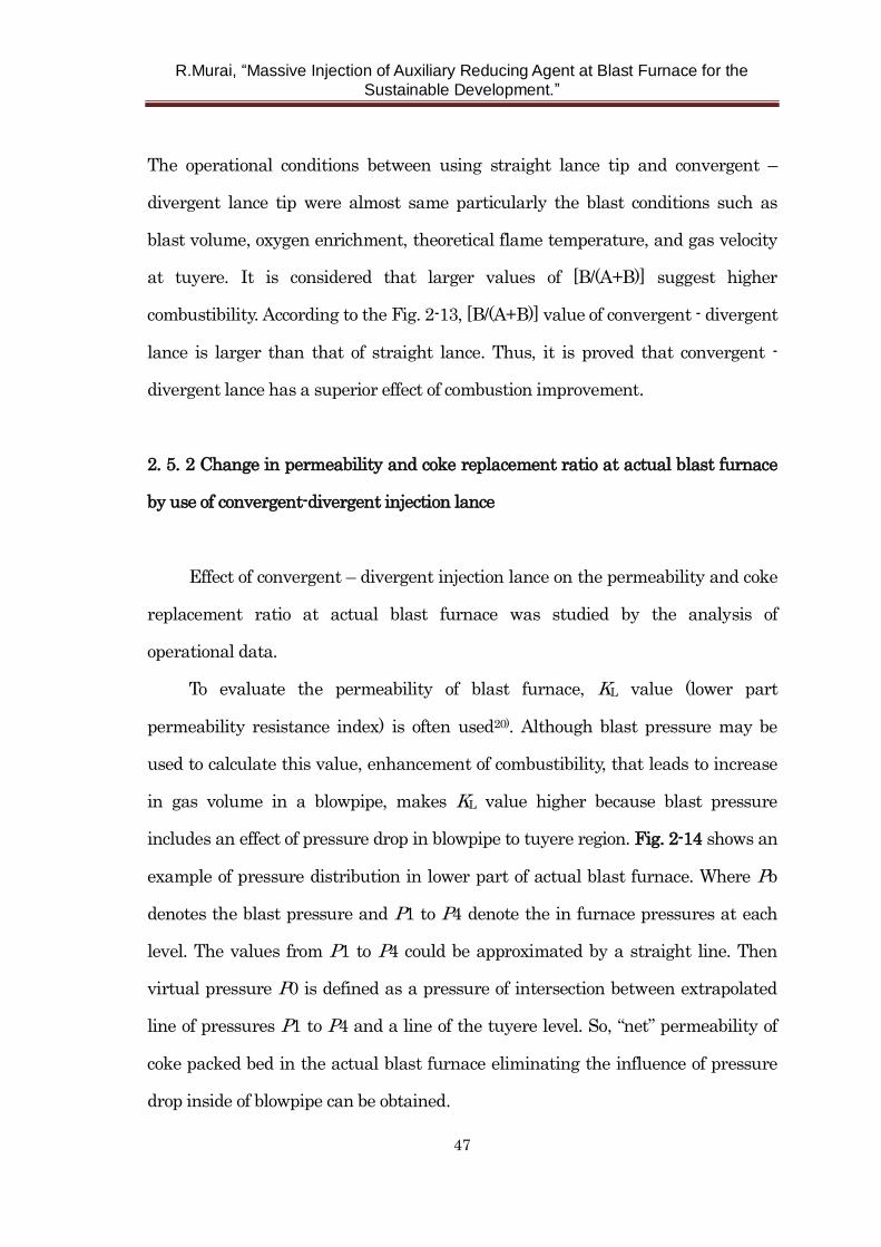
zone a and zone b respectively. The calculation results of [B/(A+B)] are shown in
Fig. 2-13. The operational conditions of actual blast furnace are shown in Table
2-2.
Fig. 2-12 Analysis method of combustibility by the image processing.
R.Murai, “Massive Injection of Auxiliary Reducing Agent at Blast Furnace for the
Sustainable Development.”
46
Fig. 2-13 Combustibility index [B/(A+B)] measured in actual blast furnace.
Table 2-2 Operation conditions of actual blast furnace.
R.Murai, “Massive Injection of Auxiliary Reducing Agent at Blast Furnace for the
Sustainable Development.”
47
The operational conditions between using straight lance tip and convergent –
divergent lance tip were almost same particularly the blast conditions such as
blast volume, oxygen enrichment, theoretical flame temperature, and gas velocity
at tuyere. It is considered that larger values of [B/(A+B)] suggest higher
combustibility. According to the Fig. 2-13, [B/(A+B)] value of convergent - divergent
lance is larger than that of straight lance. Thus, it is proved that convergent -
divergent lance has a superior effect of combustion improvement.
2. 5. 2 Change in permeability and coke replacement ratio at actual blast furnace
by use of convergent-divergent injection lance
Effect of convergent – divergent injection lance on the permeability and coke
replacement ratio at actual blast furnace was studied by the analysis of
operational data.
To evaluate the permeability of blast furnace, KL value (lower part
permeability resistance index) is often used20). Although blast pressure may be
used to calculate this value, enhancement of combustibility, that leads to increase
in gas volume in a blowpipe, makes KL value higher because blast pressure
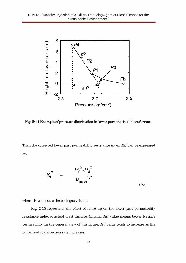
includes an effect of pressure drop in blowpipe to tuyere region. Fig. 2-14 shows an
example of pressure distribution in lower part of actual blast furnace. Where Pb
denotes the blast pressure and P1 to P4 denote the in furnace pressures at each
level. The values from P1 to P4 could be approximated by a straight line. Then
virtual pressure P0 is defined as a pressure of intersection between extrapolated
line of pressures P1 to P4 and a line of the tuyere level. So, “net” permeability of
coke packed bed in the actual blast furnace eliminating the influence of pressure
drop inside of blowpipe can be obtained.
R.Murai, “Massive Injection of Auxiliary Reducing Agent at Blast Furnace for the
Sustainable Development.”
48
Fig. 2-14 Example of pressure distribution in lower part of actual blast furnace.
Then the corrected lower part permeability resistance index KL* can be expressed
as,
(2-5)
where Vbosh denotes the bosh gas volume.
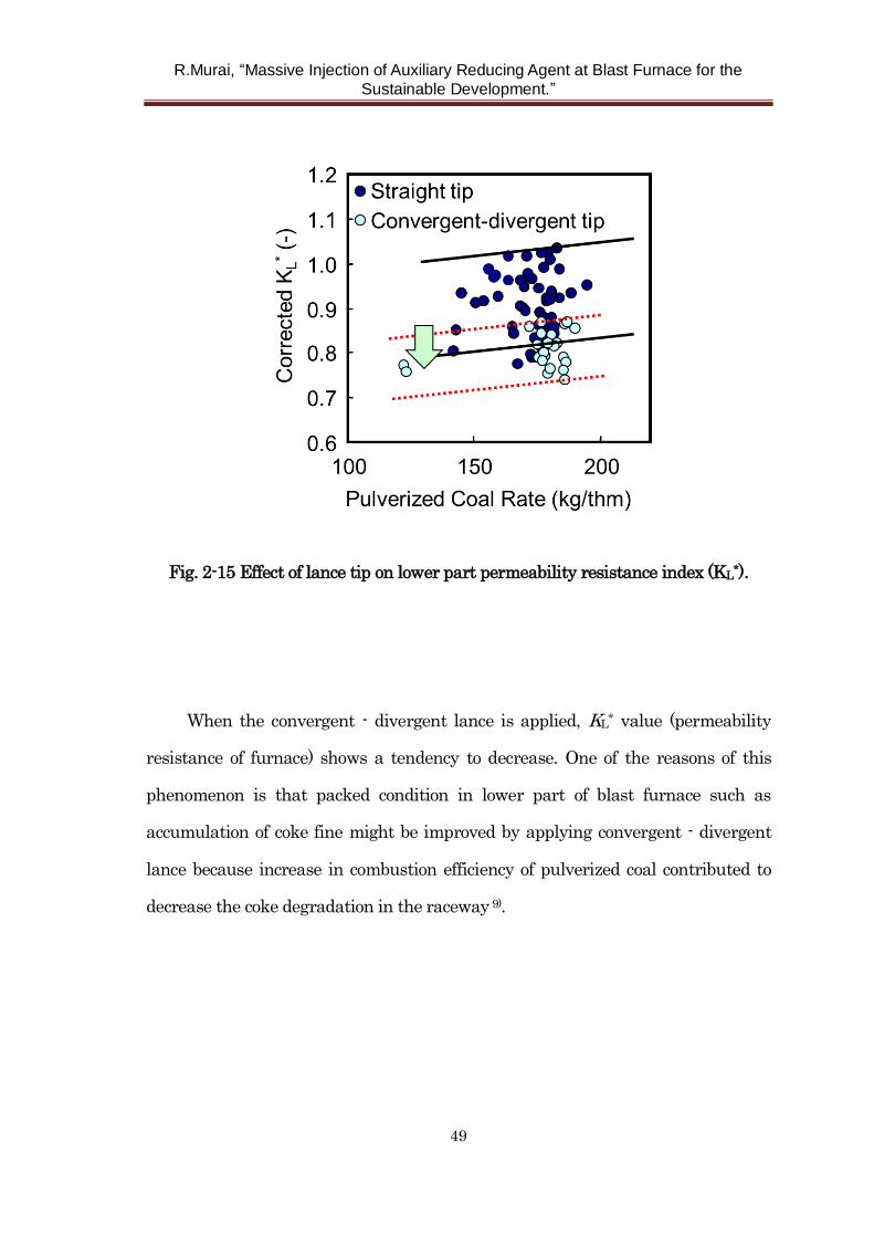
Fig. 2-15 represents the effect of lance tip on the lower part permeability
resistance index of actual blast furnace. Smaller KL* value means better furnace
permeability. In the general view of this figure, KL* value tends to increase as the
pulverized coal injection rate increases.
R.Murai, “Massive Injection of Auxiliary Reducing Agent at Blast Furnace for the
Sustainable Development.”
49
Fig. 2-15 Effect of lance tip on lower part permeability resistance index (KL*).
When the convergent - divergent lance is applied, KL* value (permeability
resistance of furnace) shows a tendency to decrease. One of the reasons of this
phenomenon is that packed condition in lower part of blast furnace such as
accumulation of coke fine might be improved by applying convergent - divergent
lance because increase in combustion efficiency of pulverized coal contributed to
decrease the coke degradation in the raceway 9).
R.Murai, “Massive Injection of Auxiliary Reducing Agent at Blast Furnace for the
Sustainable Development.”
50
2. 6 Conclusions
Aiming at enhancing the combustion efficiency of pulverized coal at blast
furnace, the convergent – divergent injection lance was proposed. Through the
experiments conducted by offline apparatus, hot model and actual blast furnace,
the following results were obtained.
(1) Optimum divergence angle where the particle dispersibility is maximized
proved to be around 7 degrees by the observation results of offline apparatus. This
angle could be explained by the theory of flow separation in the boundary layer.
(2) Optimum convergence angle where the particle dispersibility is
maximized proved to be around 5 degrees by the observation results of offline
apparatus. Due to the inertia of coal particles, segregation of particle to relatively
peripheral region at the throat part in the lance may be occurred. It was thought
that this segregation phenomenon played significant role to the good dispersibility
of the lance.
(3) The observation results of dispersion behavior by hot model experimental
furnace showed that higher dispersibility of convergent - divergent lance could be
conserved not only offline ambient atmosphere but even in a high-speed hot blast.
(4) Coke replacement ratio measured by hot model is higher in the case of
convergent - divergent injection lance. It is estimated that reason of this result is
attributed to increase in combustion efficiency by enhancement of particle
dispersion.
(5) Characteristics of the convergent – divergent injection lance including
higher particle dispersibility, higher combustibility, and higher coke replacement
ratio compared with normal straight injection lance proved in the actual blast
furnace.
R.Murai, “Massive Injection of Auxiliary Reducing Agent at Blast Furnace for the
Sustainable Development.”
51
References
1) S. Hayashi, G. Suzuki and T. Kobayashi: Tetsu-to-Hagane, 49(1963), 655.
2) M. Kawabe, S. Wakuri, M. Baba, Y. Ishikawa and A. Hasegawa:
Tetsu-to-Hagane, 68(1982), 2393.
3) M. Chu, H. Nogami and J. Yagi: ISIJ int., 44(2004), 801.
4) R. Murai, M. Sato and T. Ariyama: ISIJ int., 44(2004), 2168.
5) K. Yamaguchi, T. Uno, T. Yamamoto, H. Ueno, N. Konno and S. Matsuzaki:
Tetsu-to-Hagane, 82(1996), 641.
6) K. Tamura, M. Ichida, H. Wakimoto, K. Ono and Y. Hayashi: Tetsu-to-Hagane,
73(1987), 1980.
7) M. Ichida, T. Nakayama, K. Tamura, H. Shiota, K. Araki and Y. Sugisaki:
Tetsu-to-Hagane, 78(1992), 1132.
8) A. Kasai, H. Iwakiri, T. kamijo and M. Shimizu: Tetsu-to-Hagane, 83(1997), 551.
9) M. Sato, R. Murai, T. Ariyama, A. Maki, A. Shimomura and K. Mori:
Tetsu-to-Hagane, 85(1999), 717.
10) R. Ito, Y. Yoshida, K. Hoshino, F. Noma and T. Suzuki: Kobe Steel Eng. Rep.,
50(2000), 6.
11) M. Sato, R. Murai, T. Ariyama, A. Maki, A. Shimomura and K. Mori:
Tetsu-to-Hagane, 84(1998), 37.
12) N. Ishiwata, T. Uchiyama and K. Takeda: Kawasaki Steel Giho, 29(1997), 37.
13) J. W. Wikstrom, B. E. Skold and K. Karsud: Ironmaking Conference
Proceedings, AIST, Warrendale, (1996), 61.
14) R. Murai, M Sato and T. Ariyama: CAMP-ISIJ, 10(1997), 121.
15) A. H. Gibson: Proc. Roy. Soc., A83(1920), 366.
16) E. M. Sparrow, J. P. Abraham and W. J. Minkowycz: International Journal of
R.Murai, “Massive Injection of Auxiliary Reducing Agent at Blast Furnace for the
Sustainable Development.”
52
Heat and Mass Transfer, 52(2009), 3079.
17) R. W. Fox and S. J. Kline: J. of Fluids Engineering, 84(1962), 303.
18) J. P. Johnston: J.of Fluids Engineering, 120(1998), 6.
19) T. Ariyama, M. Sato, Y. Yamakawa, Y. Yamada and M. Suzuki:
Tetsu-to-Hagane, 80(1994), 288.
20) K. Ishii: Advanced Pulverized Coal Injection Technology and Blast Furnace
Operation, Pergamon Press, Oxford, (2000),149.
R.Murai, “Massive Injection of Auxiliary Reducing Agent at Blast Furnace for the
Sustainable Development.”
53
Chapter 3 Flow behavior of plastic particle as auxiliary
reducing agent in the blast furnace
3. 1 Introduction
As an alternative reducing agent, plastics has been injected to blast furnaces
aiming at mitigation of carbon dioxide emissions and attainment of sustainable
development1-3). Injected plastics may cause high temperature reactions such as
gasification in lower part of blast furnace. It is well known that a part of injected
plastics generates unburnt char as a result of incomplete gasification. Unburnt
char particles, consisting of fixed carbon and ash, are considered to be conveyed
with gas flow. And then, they may be consumed completely by the direct reduction
at the cohesive zone or they may be accumulated somewhere in coke packed bed.
Several researches concerning pyrolysis of plastic particles have been
reported. For example, Ariyama et al.4) researched gasification and combustion
behavior of single plastic particle in the laminar flow furnace. Yamaguchi et al.5)
investigated the behavior of plastic in blow pipe and raceway using vertical tower
furnace and hot model. Goto et al.6) estimated the behavior of plastics in a blast
furnace by numerical simulations and the simulation results were verified by the
hot model experiments. However, these previous researches focused on the
pyrolysis of plastic particles from blowpipe to raceway region, research on the flow
behavior of plastic particles and unburnt char in lower part of blast furnace
including outer part of raceway is very few. Some plastics has high alumina
content of ash, so slag flowability becomes worse. Accumulation of unburnt char in
particular part may cause unstable operation of blast furnace because of slag
drainage problem7).
R.Murai, “Massive Injection of Auxiliary Reducing Agent at Blast Furnace for the
Sustainable Development.”
54
There are various shapes of “used” plastics such as film, grain, lump, sheet,
and bar. Processing methods of these plastics to use at blast furnace have been
reported. Thin-film shape plastics tend to clog up the injection lines, so they are
often agglomerated into granular shape using extruder for instance8). In the case of
crushing large-size plastics, a part of crushing energy may change into heat, and
temperature of plastics increases. As previously reported9), “used” plastics are
composed of polyethylene, polypropylene, polystyrene, and so on. Pulverizing of
plastics is considerably difficult above glass transition temperature of these
plastics components. So, large-size plastics have been used to inject after crushing
into rather coarse grain in the early stage3).
Recently, pulverizing method of plastics has been developed and fine plastics
have been injected practically at a particular blast furnace7). However, effects of
particle size of injected plastics on the operation of blast furnace such as
permeability were not clear.
The author, at first, made a model of gasification behavior of plastic particles
based on the observation result of plastic injection experiment using experimental
furnace which is able to achieve rapid heating condition same as an actual blast
furnace. Then, the gasification rate of unburnt char has been quantified by the
thermogravimetric analysis. Next, using the results mentioned above, flow and
accumulation behavior of plastic particles and unburnt char in lower part of blast
furnace was clarified by numerical simulations.
In this chapter, effect of initial size of injected plastics on the blast furnace
operation is discussed and verified using operation data at actual blast furnace.
R.Murai, “Massive Injection of Auxiliary Reducing Agent at Blast Furnace for the
Sustainable Development.”
55
3. 2 Characteristics of plastic gasification
3. 2. 1 Modeling of plastic gasification
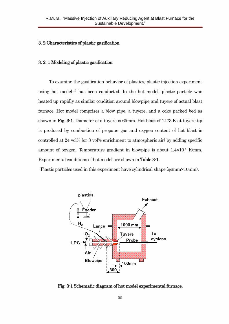
To examine the gasification behavior of plastics, plastic injection experiment
using hot model10) has been conducted. In the hot model, plastic particle was
heated up rapidly as similar condition around blowpipe and tuyere of actual blast
furnace. Hot model comprises a blow pipe, a tuyere, and a coke packed bed as
shown in Fig. 3-1. Diameter of a tuyere is 65mm. Hot blast of 1473 K at tuyere tip
is produced by combustion of propane gas and oxygen content of hot blast is
controlled at 24 vol% (or 3 vol% enrichment to atmospheric air) by adding specific
amount of oxygen. Temperature gradient in blowpipe is about 1.4×10⁻¹ K/mm.
Experimental conditions of hot model are shown in Table 3-1.
Plastic particles used in this experiment have cylindrical shape (φ6mm×10mm).
Fig. 3-1 Schematic diagram of hot model experimental furnace.
R.Murai, “Massive Injection of Auxiliary Reducing Agent at Blast Furnace for the
Sustainable Development.”
56
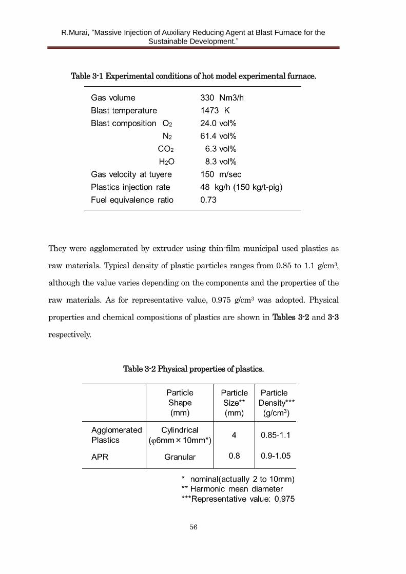
Table 3-1 Experimental conditions of hot model experimental furnace.
They were agglomerated by extruder using thin-film municipal used plastics as
raw materials. Typical density of plastic particles ranges from 0.85 to 1.1 g/cm3,
although the value varies depending on the components and the properties of the
raw materials. As for representative value, 0.975 g/cm3 was adopted. Physical
properties and chemical compositions of plastics are shown in Tables 3-2 and 3-3
respectively.
Table 3-2 Physical properties of plastics.
R.Murai, “Massive Injection of Auxiliary Reducing Agent at Blast Furnace for the
Sustainable Development.”
57
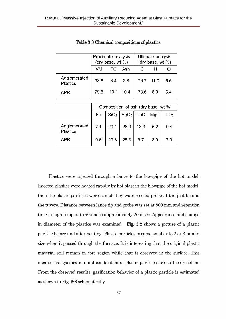
Table 3-3 Chemical compositions of plastics.
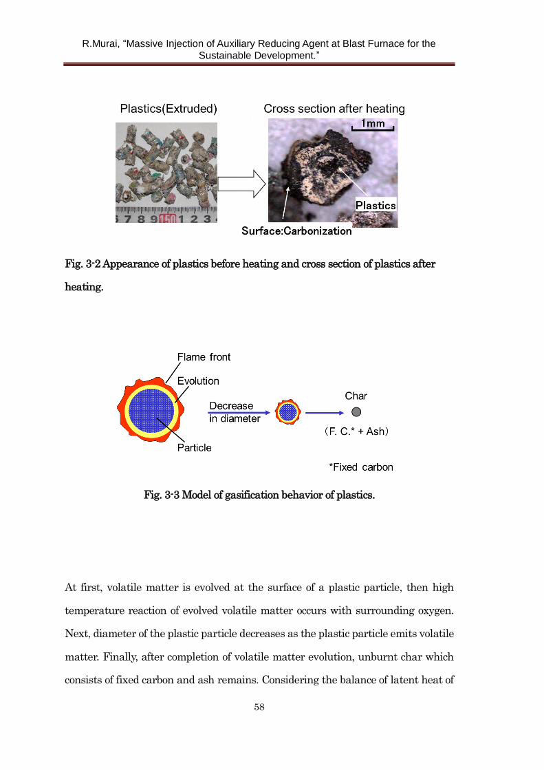
Plastics were injected through a lance to the blowpipe of the hot model.
Injected plastics were heated rapidly by hot blast in the blowpipe of the hot model,
then the plastic particles were sampled by water-cooled probe at the just behind
the tuyere. Distance between lance tip and probe was set at 800 mm and retention
time in high temperature zone is approximately 20 msec. Appearance and change
in diameter of the plastics was examined. Fig. 3-2 shows a picture of a plastic
particle before and after heating. Plastic particles became smaller to 2 or 3 mm in
size when it passed through the furnace. It is interesting that the original plastic
material still remain in core region while char is observed in the surface. This
means that gasification and combustion of plastic particles are surface reaction.
From the observed results, gasification behavior of a plastic particle is estimated
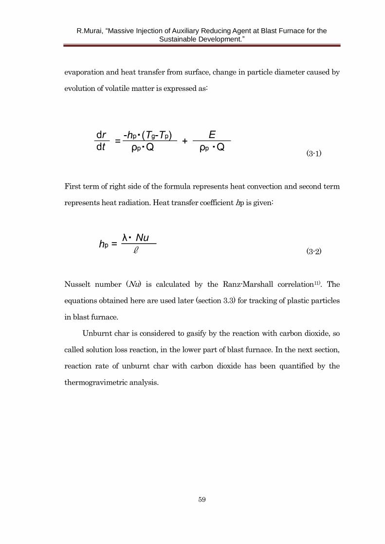
as shown in Fig. 3-3 schematically.
R.Murai, “Massive Injection of Auxiliary Reducing Agent at Blast Furnace for the
Sustainable Development.”
58
Fig. 3-2 Appearance of plastics before heating and cross section of plastics after
heating.
Fig. 3-3 Model of gasification behavior of plastics.
At first, volatile matter is evolved at the surface of a plastic particle, then high
temperature reaction of evolved volatile matter occurs with surrounding oxygen.
Next, diameter of the plastic particle decreases as the plastic particle emits volatile
matter. Finally, after completion of volatile matter evolution, unburnt char which
consists of fixed carbon and ash remains. Considering the balance of latent heat of
R.Murai, “Massive Injection of Auxiliary Reducing Agent at Blast Furnace for the
Sustainable Development.”
59
evaporation and heat transfer from surface, change in particle diameter caused by
evolution of volatile matter is expressed as:
(3-1)
First term of right side of the formula represents heat convection and second term
represents heat radiation. Heat transfer coefficient hp is given:
(3-2)
Nusselt number (Nu) is calculated by the Ranz-Marshall correlation11). The
equations obtained here are used later (section 3.3) for tracking of plastic particles
in blast furnace.
Unburnt char is considered to gasify by the reaction with carbon dioxide, so
called solution loss reaction, in the lower part of blast furnace. In the next section,
reaction rate of unburnt char with carbon dioxide has been quantified by the
thermogravimetric analysis.
R.Murai, “Massive Injection of Auxiliary Reducing Agent at Blast Furnace for the
Sustainable Development.”
60
3. 2. 2 Reaction rate of char derived from plastics
To obtain unburnt char derived from plastics, plastic particles were heated by
electric furnace in inert gas (high purity nitrogen) atmosphere.
Two kinds of plastics were used in this experiment. Agglomerated plastics are
same as mentioned previous section. APR7) represents fine plastics made by
advanced plastic processing method. In this process, Plastics were pulverized
using residual stress acts between interfaces of plastics which was provided when
different kinds of plastics were cooled to room temperature after melting and
mixing. The cost to pulverize plastics is reduced by using residual stress. In this
experiment, raw materials to produce agglomerated plastics and raw materials to
produce APR were made equal to each other, that is, thin-film municipal used
plastics were used as raw materials. Physical properties and chemical composition
of APR are shown together with those of agglomerated plastics in Table 3-2 and 3-3
respectively. Typical diameter of APR is 0.8mm while that of agglomerated plastics
is 4mm.
Fig. 3-4 shows an experimental apparatus for the carbonization of plastics.
Temperature of electric furnace was increased up to 1273 K at a rate of 7 degrees
per minute. Specimen was mounted on the quartz boat (75mm in length, 10mm in
width and 10mm in height). The amount of specimen was 1g in each case. The
boat can be slid from the edge to center of reaction tube. Diameter of reaction tube
is 35mm. Nitrogen gas was fed to the reaction tube at the rate of 100 cm3/min.
Rapid heating can be carried out by sliding boat from edge to center immediately
when center part temperature reaches designated value. And for the gradual
heating, boat was fixed at center part throughout the heating process.
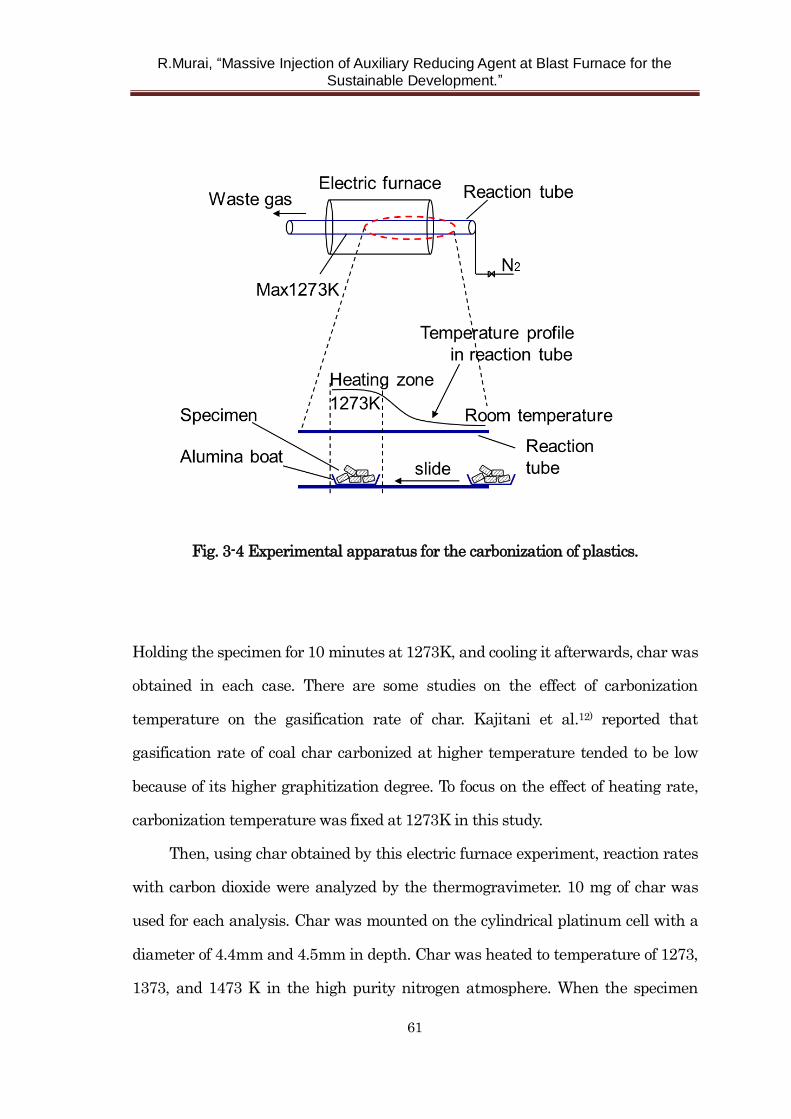
R.Murai, “Massive Injection of Auxiliary Reducing Agent at Blast Furnace for the
Sustainable Development.”
61
Fig. 3-4 Experimental apparatus for the carbonization of plastics.
Holding the specimen for 10 minutes at 1273K, and cooling it afterwards, char was
obtained in each case. There are some studies on the effect of carbonization
temperature on the gasification rate of char. Kajitani et al.12) reported that
gasification rate of coal char carbonized at higher temperature tended to be low
because of its higher graphitization degree. To focus on the effect of heating rate,
carbonization temperature was fixed at 1273K in this study.
Then, using char obtained by this electric furnace experiment, reaction rates
with carbon dioxide were analyzed by the thermogravimeter. 10 mg of char was
used for each analysis. Char was mounted on the cylindrical platinum cell with a
diameter of 4.4mm and 4.5mm in depth. Char was heated to temperature of 1273,
1373, and 1473 K in the high purity nitrogen atmosphere. When the specimen
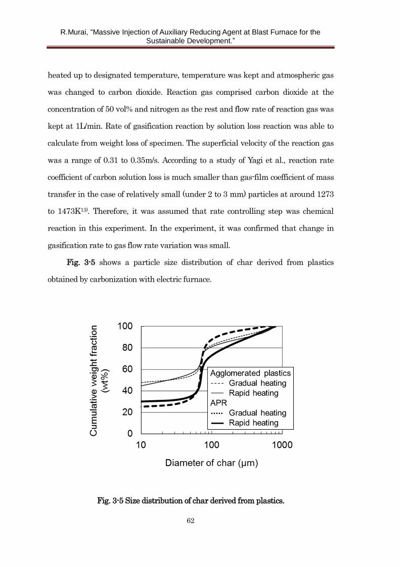
R.Murai, “Massive Injection of Auxiliary Reducing Agent at Blast Furnace for the
Sustainable Development.”
62
heated up to designated temperature, temperature was kept and atmospheric gas
was changed to carbon dioxide. Reaction gas comprised carbon dioxide at the
concentration of 50 vol% and nitrogen as the rest and flow rate of reaction gas was
kept at 1L/min. Rate of gasification reaction by solution loss reaction was able to
calculate from weight loss of specimen. The superficial velocity of the reaction gas
was a range of 0.31 to 0.35m/s. According to a study of Yagi et al., reaction rate
coefficient of carbon solution loss is much smaller than gas-film coefficient of mass
transfer in the case of relatively small (under 2 to 3 mm) particles at around 1273
to 1473K13). Therefore, it was assumed that rate controlling step was chemical
reaction in this experiment. In the experiment, it was confirmed that change in
gasification rate to gas flow rate variation was small.
Fig. 3-5 shows a particle size distribution of char derived from plastics
obtained by carbonization with electric furnace.
Fig. 3-5 Size distribution of char derived from plastics.
R.Murai, “Massive Injection of Auxiliary Reducing Agent at Blast Furnace for the
Sustainable Development.”
63
Laser diffraction method was used to analyze particle size distribution. Particle
size of char is characterized by 1) existence of fine particles under 10 µm, 2) rather
narrow distribution around 60-80 µm and 3) existence of relatively coarse particle
over 100 µm. Kinds of plastics and rate of heating do not affect particle size of
unburnt char greatly. Sugiyama14) reported the condition of powder accumulation
in the deadman. He suggested that coke fine which is over 500µm in size caused
hold-up in the lower part of blast furnace. It is considered that hold-up of fine in
lower part of blast furnace may cause unstable operation. So the condition of
accumulation of unburnt char derived from plastics is discussed later.
Fig. 3-6 shows results of char gasification experiments with carbon dioxide
(Arrhenius plot). Gasification rate of char obtained by rapid heating tends to be
larger than that of char by gradual heating. On the other hand, gasification rate
does not depend on the kind of plastics greatly.
It is considered that gasification rate of char is influenced by specific surface
area. Therefore surfaces of various char are observed with scanning electron
microscope. The results are shown in Fig. 3-7. Several micro pores are observed on
the surface of rapid heating char, while surface of char heated gradually seems to
be rather smooth. As the rate of volatile matter evolution is fast in the case of rapid
heating char, pores are formed on the surface. As a result, it is estimated that
specific surface area is increased and gasification rate is also increased. These
results agree very well with the study on the gasification rate of the char derived
from coal by Luo et al15).
There are various models describing the kinetics of a gas-solid reaction, such
as the volume-reaction model, the shrinking-core model, and the random-pore
model16-19).
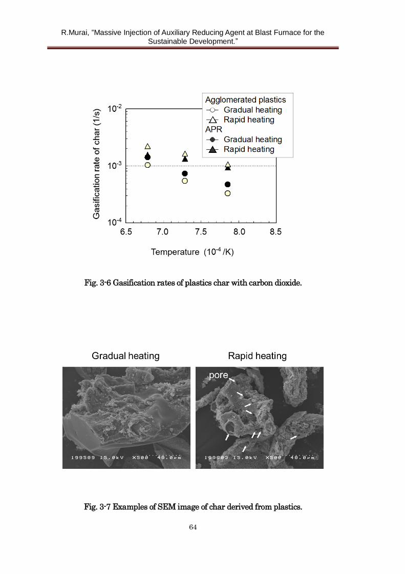
R.Murai, “Massive Injection of Auxiliary Reducing Agent at Blast Furnace for the
Sustainable Development.”
64
Fig. 3-6 Gasification rates of plastics char with carbon dioxide.
Fig. 3-7 Examples of SEM image of char derived from plastics.
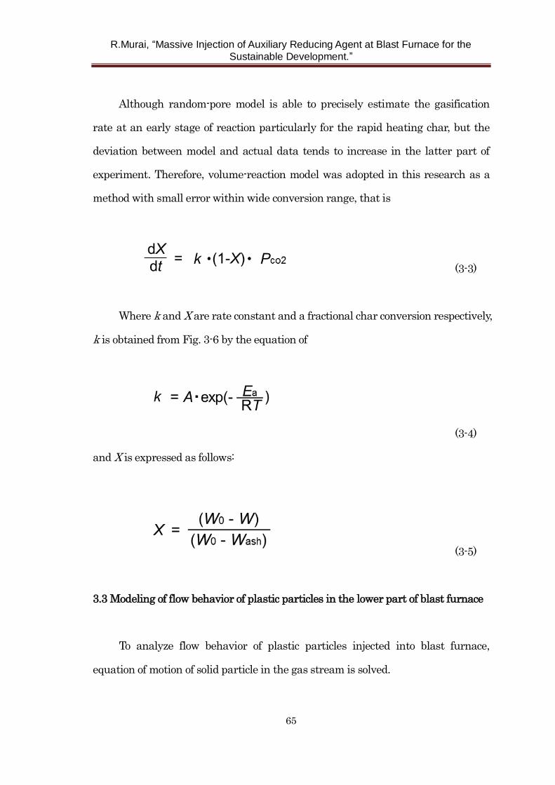
R.Murai, “Massive Injection of Auxiliary Reducing Agent at Blast Furnace for the
Sustainable Development.”
65
Although random-pore model is able to precisely estimate the gasification
rate at an early stage of reaction particularly for the rapid heating char, but the
deviation between model and actual data tends to increase in the latter part of
experiment. Therefore, volume-reaction model was adopted in this research as a
method with small error within wide conversion range, that is
(3-3)
Where k and X are rate constant and a fractional char conversion respectively,
k is obtained from Fig. 3-6 by the equation of
(3-4)
and X is expressed as follows:
(3-5)
3.3 Modeling of flow behavior of plastic particles in the lower part of blast furnace
To analyze flow behavior of plastic particles injected into blast furnace,
equation of motion of solid particle in the gas stream is solved.
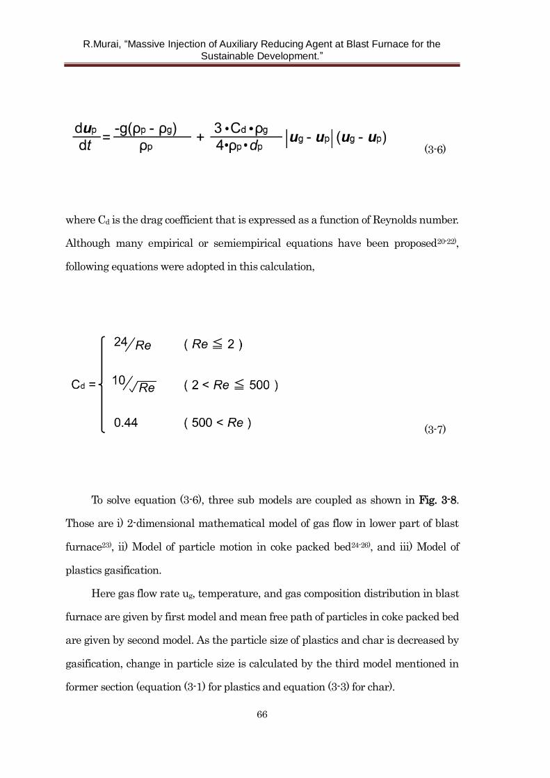
R.Murai, “Massive Injection of Auxiliary Reducing Agent at Blast Furnace for the
Sustainable Development.”
66
(3-6)
where Cd is the drag coefficient that is expressed as a function of Reynolds number.
Although many empirical or semiempirical equations have been proposed20-22),
following equations were adopted in this calculation,
(3-7)
To solve equation (3-6), three sub models are coupled as shown in Fig. 3-8.
Those are i) 2-dimensional mathematical model of gas flow in lower part of blast
furnace23), ii) Model of particle motion in coke packed bed24-26), and iii) Model of
plastics gasification.
Here gas flow rate ug, temperature, and gas composition distribution in blast
furnace are given by first model and mean free path of particles in coke packed bed
are given by second model. As the particle size of plastics and char is decreased by
gasification, change in particle size is calculated by the third model mentioned in
former section (equation (3-1) for plastics and equation (3-3) for char).
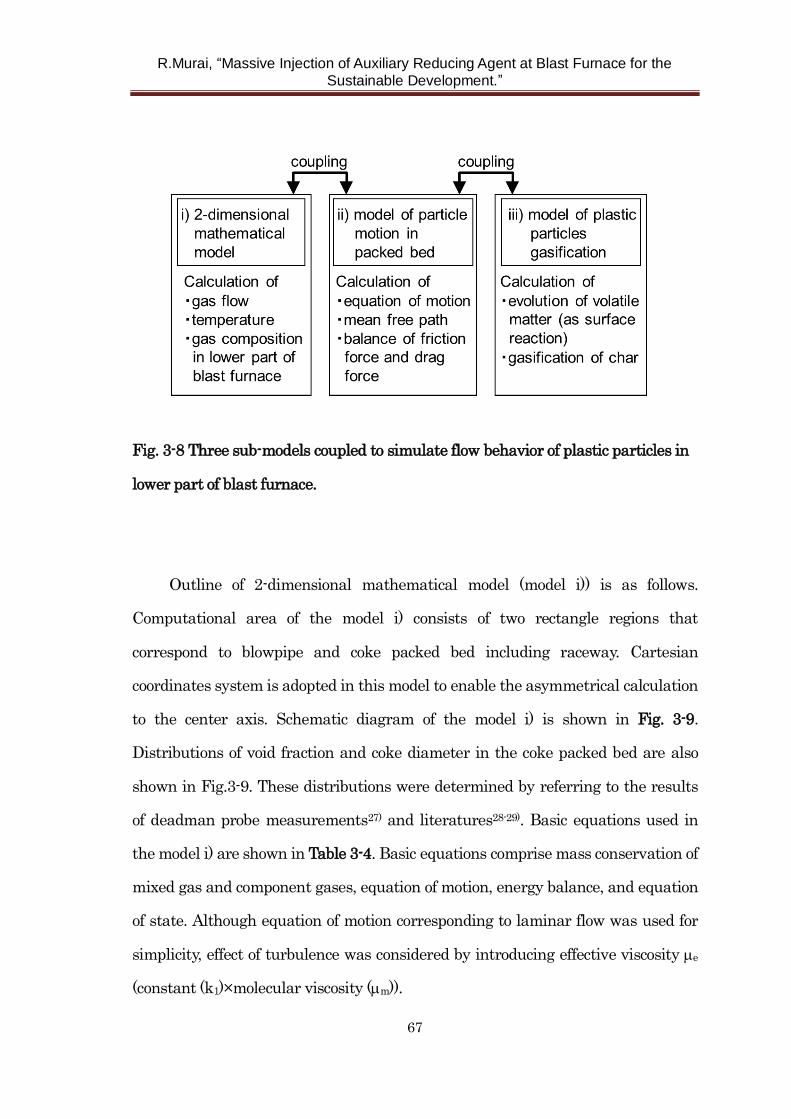
R.Murai, “Massive Injection of Auxiliary Reducing Agent at Blast Furnace for the
Sustainable Development.”
67
Fig. 3-8 Three sub-models coupled to simulate flow behavior of plastic particles in
lower part of blast furnace.
Outline of 2-dimensional mathematical model (model i)) is as follows.
Computational area of the model i) consists of two rectangle regions that
correspond to blowpipe and coke packed bed including raceway. Cartesian
coordinates system is adopted in this model to enable the asymmetrical calculation
to the center axis. Schematic diagram of the model i) is shown in Fig. 3-9.
Distributions of void fraction and coke diameter in the coke packed bed are also
shown in Fig.3-9. These distributions were determined by referring to the results
of deadman probe measurements27) and literatures28-29). Basic equations used in
the model i) are shown in Table 3-4. Basic equations comprise mass conservation of
mixed gas and component gases, equation of motion, energy balance, and equation
of state. Although equation of motion corresponding to laminar flow was used for
simplicity, effect of turbulence was considered by introducing effective viscosity e
(constant (k1)×molecular viscosity (m)).
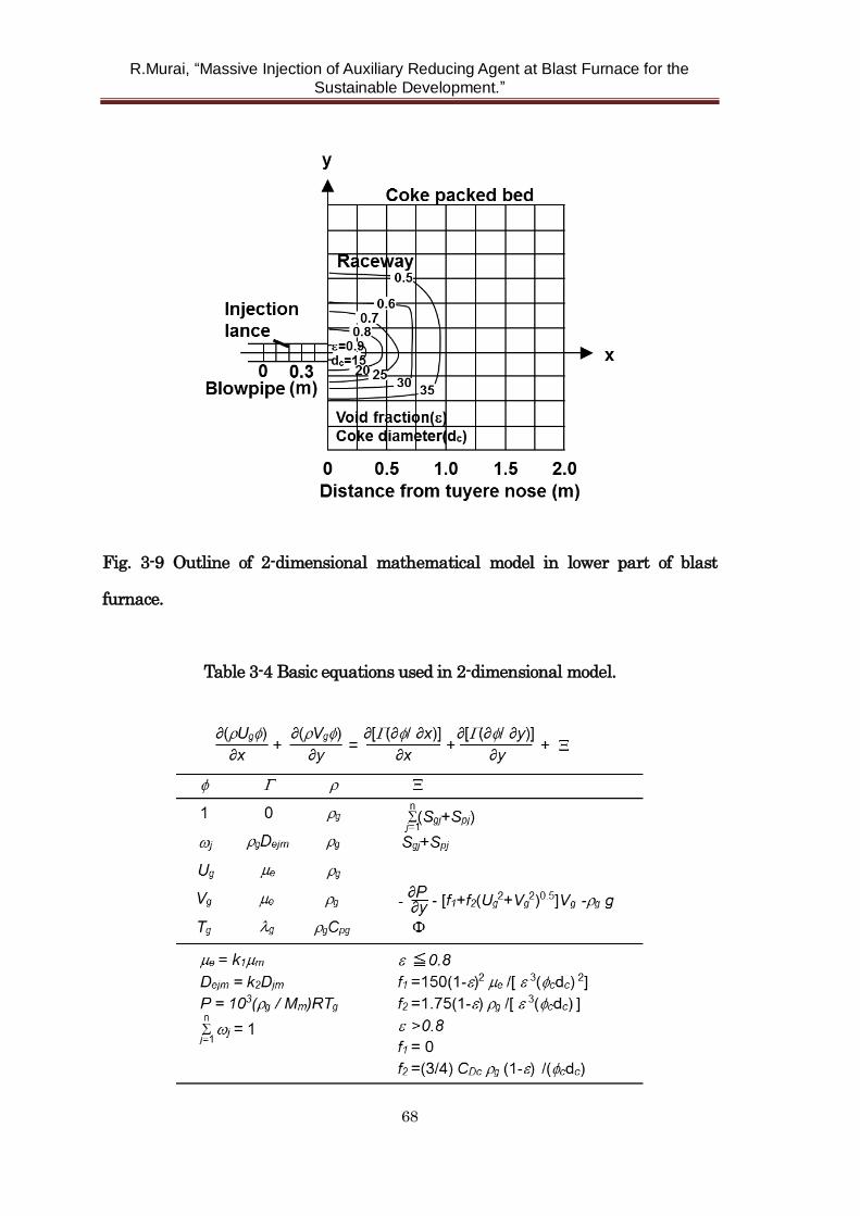
R.Murai, “Massive Injection of Auxiliary Reducing Agent at Blast Furnace for the
Sustainable Development.”
68
Fig. 3-9 Outline of 2-dimensional mathematical model in lower part of blast
furnace.
Table 3-4 Basic equations used in 2-dimensional model.
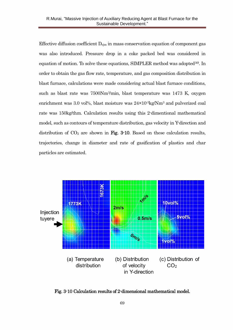
R.Murai, “Massive Injection of Auxiliary Reducing Agent at Blast Furnace for the
Sustainable Development.”
69
Effective diffusion coefficient Dejm in mass conservation equation of component gas
was also introduced. Pressure drop in a coke packed bed was considered in
equation of motion. To solve these equations, SIMPLER method was adopted30). In
order to obtain the gas flow rate, temperature, and gas composition distribution in
blast furnace, calculations were made considering actual blast furnace conditions,
such as blast rate was 7500Nm3/min, blast temperature was 1473 K, oxygen
enrichment was 3.0 vol%, blast moisture was 24×10-3kg/Nm3 and pulverized coal
rate was 150kg/thm. Calculation results using this 2-dimentional mathematical
model, such as contours of temperature distribution, gas velocity in Y-direction and
distribution of CO2 are shown in Fig. 3-10. Based on these calculation results,
trajectories, change in diameter and rate of gasification of plastics and char
particles are estimated.
Fig. 3-10 Calculation results of 2-dimensional mathematical model.
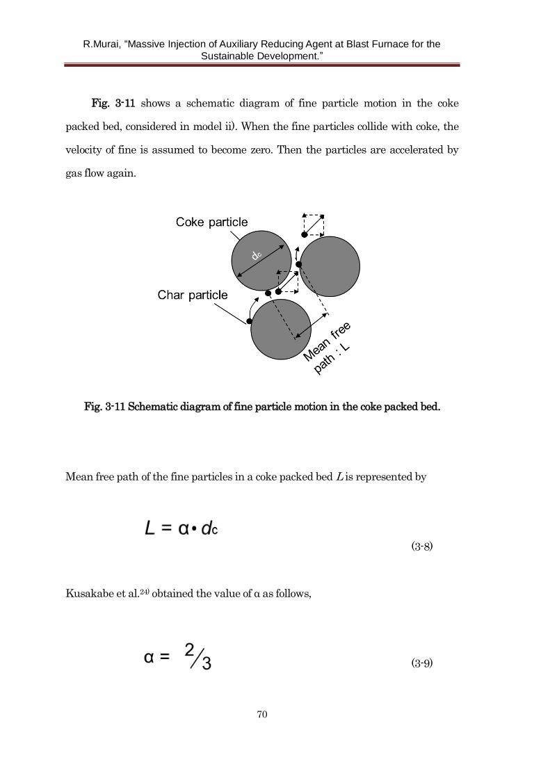
R.Murai, “Massive Injection of Auxiliary Reducing Agent at Blast Furnace for the
Sustainable Development.”
70
Fig. 3-11 shows a schematic diagram of fine particle motion in the coke
packed bed, considered in model ii). When the fine particles collide with coke, the
velocity of fine is assumed to become zero. Then the particles are accelerated by
gas flow again.
Fig. 3-11 Schematic diagram of fine particle motion in the coke packed bed.
Mean free path of the fine particles in a coke packed bed L is represented by
(3-8)
Kusakabe et al.24) obtained the value of α as follows,
(3-9)
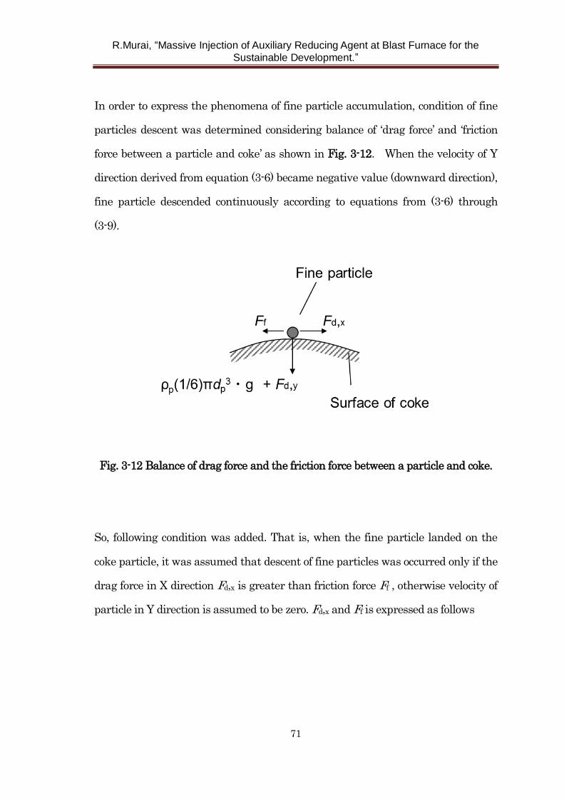
R.Murai, “Massive Injection of Auxiliary Reducing Agent at Blast Furnace for the
Sustainable Development.”
71
In order to express the phenomena of fine particle accumulation, condition of fine
particles descent was determined considering balance of ‘drag force’ and ‘friction
force between a particle and coke’ as shown in Fig. 3-12. When the velocity of Y
direction derived from equation (3-6) became negative value (downward direction),
fine particle descended continuously according to equations from (3-6) through
(3-9).
Fig. 3-12 Balance of drag force and the friction force between a particle and coke.
So, following condition was added. That is, when the fine particle landed on the
coke particle, it was assumed that descent of fine particles was occurred only if the
drag force in X direction Fd,x is greater than friction force Ff , otherwise velocity of
particle in Y direction is assumed to be zero. Fd,x and Ff is expressed as follows
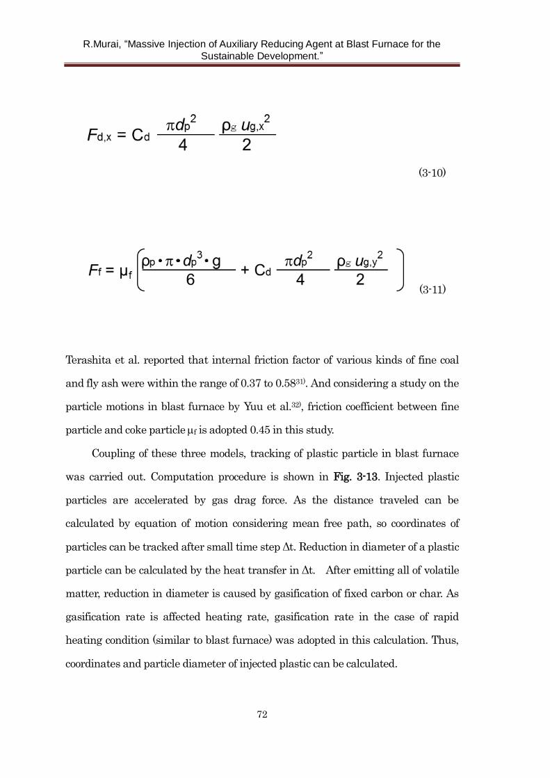
R.Murai, “Massive Injection of Auxiliary Reducing Agent at Blast Furnace for the
Sustainable Development.”
72
(3-10)
(3-11)
Terashita et al. reported that internal friction factor of various kinds of fine coal
and fly ash were within the range of 0.37 to 0.5831). And considering a study on the
particle motions in blast furnace by Yuu et al.32), friction coefficient between fine
particle and coke particle f is adopted 0.45 in this study.
Coupling of these three models, tracking of plastic particle in blast furnace
was carried out. Computation procedure is shown in Fig. 3-13. Injected plastic
particles are accelerated by gas drag force. As the distance traveled can be
calculated by equation of motion considering mean free path, so coordinates of
particles can be tracked after small time step Δt. Reduction in diameter of a plastic
particle can be calculated by the heat transfer in Δt. After emitting all of volatile
matter, reduction in diameter is caused by gasification of fixed carbon or char. As
gasification rate is affected heating rate, gasification rate in the case of rapid
heating condition (similar to blast furnace) was adopted in this calculation. Thus,
coordinates and particle diameter of injected plastic can be calculated.
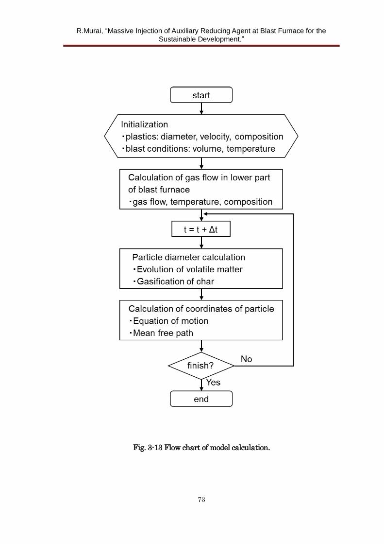
R.Murai, “Massive Injection of Auxiliary Reducing Agent at Blast Furnace for the
Sustainable Development.”
73
Fig. 3-13 Flow chart of model calculation.
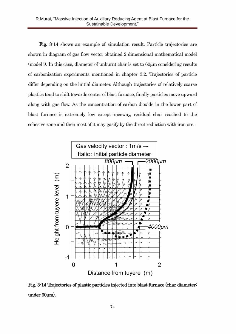
R.Murai, “Massive Injection of Auxiliary Reducing Agent at Blast Furnace for the
Sustainable Development.”
74
Fig. 3-14 shows an example of simulation result. Particle trajectories are
shown in diagram of gas flow vector obtained 2-dimensional mathematical model
(model i). In this case, diameter of unburnt char is set to 60µm considering results
of carbonization experiments mentioned in chapter 3.2. Trajectories of particle
differ depending on the initial diameter. Although trajectories of relatively coarse
plastics tend to shift towards center of blast furnace, finally particles move upward
along with gas flow. As the concentration of carbon dioxide in the lower part of
blast furnace is extremely low except raceway, residual char reached to the
cohesive zone and then most of it may gasify by the direct reduction with iron ore.
Fig. 3-14 Trajectories of plastic particles injected into blast furnace (char diameter:
under 60µm).
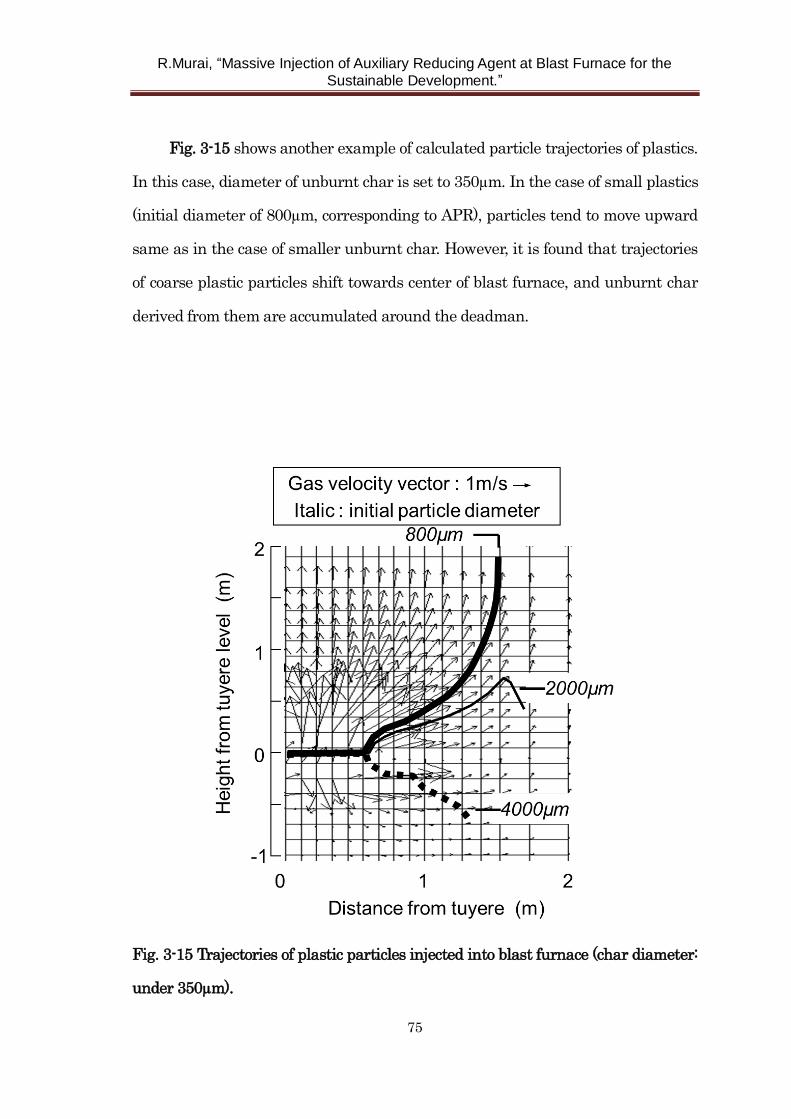
R.Murai, “Massive Injection of Auxiliary Reducing Agent at Blast Furnace for the
Sustainable Development.”
75
Fig. 3-15 shows another example of calculated particle trajectories of plastics.
In this case, diameter of unburnt char is set to 350µm. In the case of small plastics
(initial diameter of 800µm, corresponding to APR), particles tend to move upward
same as in the case of smaller unburnt char. However, it is found that trajectories
of coarse plastic particles shift towards center of blast furnace, and unburnt char
derived from them are accumulated around the deadman.
Fig. 3-15 Trajectories of plastic particles injected into blast furnace (char diameter:
under 350µm).
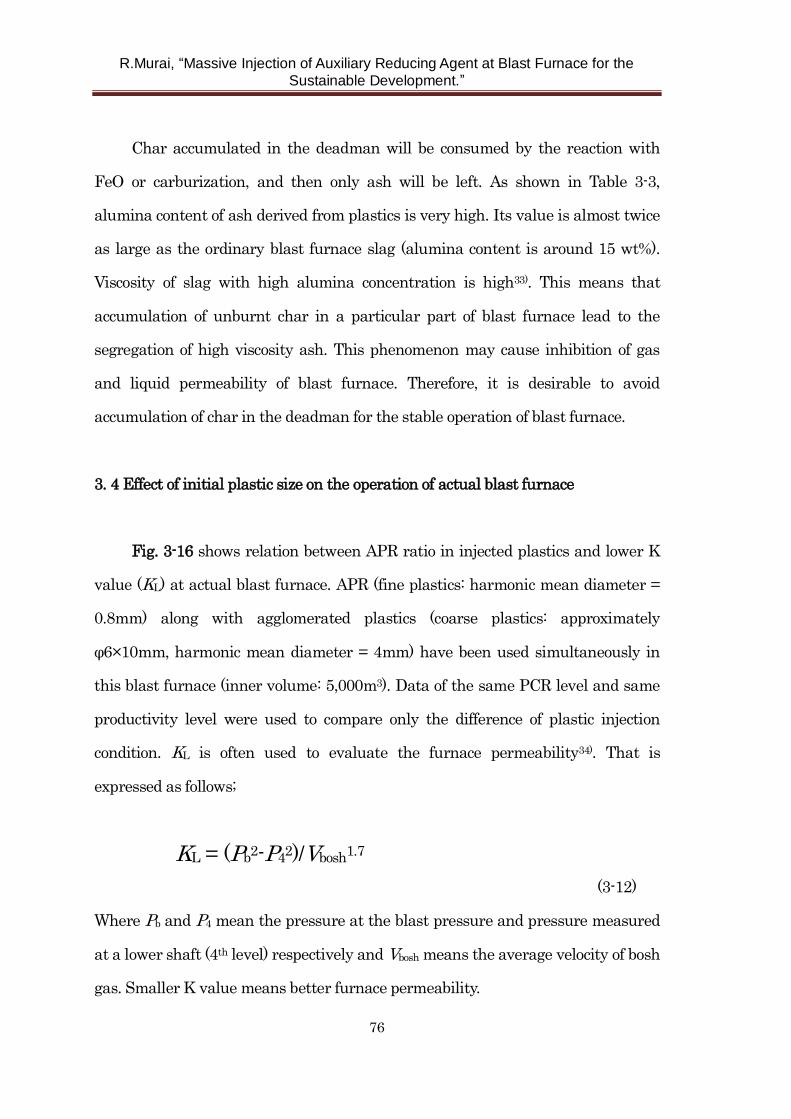
R.Murai, “Massive Injection of Auxiliary Reducing Agent at Blast Furnace for the
Sustainable Development.”
76
Char accumulated in the deadman will be consumed by the reaction with
FeO or carburization, and then only ash will be left. As shown in Table 3-3,
alumina content of ash derived from plastics is very high. Its value is almost twice
as large as the ordinary blast furnace slag (alumina content is around 15 wt%).
Viscosity of slag with high alumina concentration is high33). This means that
accumulation of unburnt char in a particular part of blast furnace lead to the
segregation of high viscosity ash. This phenomenon may cause inhibition of gas
and liquid permeability of blast furnace. Therefore, it is desirable to avoid
accumulation of char in the deadman for the stable operation of blast furnace.
3. 4 Effect of initial plastic size on the operation of actual blast furnace
Fig. 3-16 shows relation between APR ratio in injected plastics and lower K
value (KL) at actual blast furnace. APR (fine plastics: harmonic mean diameter =
0.8mm) along with agglomerated plastics (coarse plastics: approximately
φ6×10mm, harmonic mean diameter = 4mm) have been used simultaneously in
this blast furnace (inner volume: 5,000m3). Data of the same PCR level and same
productivity level were used to compare only the difference of plastic injection
condition. KL is often used to evaluate the furnace permeability34). That is
expressed as follows;
KL = (Pb2-P4
2)/Vbosh1.7
(3-12)
Where Pb and P4 mean the pressure at the blast pressure and pressure measured
at a lower shaft (4th level) respectively and Vbosh means the average velocity of bosh
gas. Smaller K value means better furnace permeability.
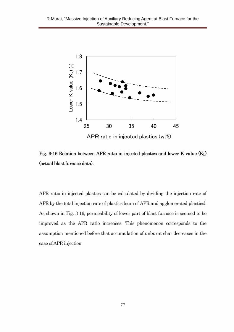
R.Murai, “Massive Injection of Auxiliary Reducing Agent at Blast Furnace for the
Sustainable Development.”
77
Fig. 3-16 Relation between APR ratio in injected plastics and lower K value (KL)
(actual blast furnace data).
APR ratio in injected plastics can be calculated by dividing the injection rate of
APR by the total injection rate of plastics (sum of APR and agglomerated plastics).
As shown in Fig. 3-16, permeability of lower part of blast furnace is seemed to be
improved as the APR ratio increases. This phenomenon corresponds to the
assumption mentioned before that accumulation of unburnt char decreases in the
case of APR injection.
R.Murai, “Massive Injection of Auxiliary Reducing Agent at Blast Furnace for the
Sustainable Development.”
78
3. 5 Conclusions
Aiming at clarifying the behavior of plastic particles injected into blast
furnace, evolution behavior of volatile matter of plastic was studied by hot model
experimental furnace and gasification behavior of unburnt char was quantified by
thermogravimetric analysis.
By using the results obtained here in the developed mathematical model, the
effect of initial size of plastic particles on the trajectory in the blast furnace was
evaluated.
1) According to the observation results of heated plastic samples obtained by
the hot model experiment, it was presumed that volatile matter of plastics was
evolved at surface of the particle.
2) Several kinds of char carbonized in different heat rates were made by
electric furnace and gasification rates of the char were analyzed by
thermogravimetric analysis. It was found that gasification rate of unburnt char
depended on the heating rate. Gasification rate in the case of rapid heating
condition tends to increase.
3) According to the observation results from scanning electron microscope,
several micro pores were observed on the surface of rapid heating char. It was
suggested that gasification rate was affected by the surface properties.
4) Trajectories of plastic particles injected into blast furnace were calculated
by mathematical model considering decrease in particle size by gasification. When
relatively small plastic was injected or diameter of unburnt char was small, it was
presumed that unburnt char went upward along with gas flow and most of it was
consumed at the cohesive zone by the direct reduction with iron ore. On the other
hand, when relatively coarse plastics was injected and diameter of unburnt char
R.Murai, “Massive Injection of Auxiliary Reducing Agent at Blast Furnace for the
Sustainable Development.”
79
was relatively coarse, it was suggested that unburnt char accumulated around the
deadman.
5) Alumina content of unburnt char derived from plastics is rather high in
general, therefore viscosity of produced slag is rather high. It is considered that
accumulation of unburnt char causes decrease in gas and liquid permeability. Thus
it is suggested that fine plastics injection is desirable for the stable operation of
blast furnace.
R.Murai, “Massive Injection of Auxiliary Reducing Agent at Blast Furnace for the
Sustainable Development.”
80
Nomenclature:
Cp specific heat at constant pressure, J/kg・K
Cd drag coefficient, -
D diffusion coefficient, m2/s
dp diameter of plastic particle, m
dc diameter of coke particle, m
E radiation energy, W/ m2
Ea activation energy, J/mol
Fd drag force, N
Ff friction force, N
g gravitational acceleration, m/sec2
hp heat transfer coefficient, W/(m・K)
k rate constant, 1/s
L mean free path, m
ℓ characteristic length, m
M molecular weight, g/mol
Nu Nusselt number, -
P pressure, kPa
Pco2 partial pressure of CO2, mol/mol
P4 pressure at shaft 4th level, kPa
Q latent heat of plastics, kJ/kg
R gas constant, J/mol・K
r particle radius, m
S rate of generation or consumption, kg/m3s
T temperature, K
R.Murai, “Massive Injection of Auxiliary Reducing Agent at Blast Furnace for the
Sustainable Development.”
81
t time, sec
u velocity, m/sec
Vbosh average velocity of bosh gas, Nm3/min
X fractional char conversion, -
W weight of char, g
Wash weight of ash in char, g
Greek letters:
α constant (calculation for mean free path), -
Φ energy dissipation term, W/m3
λ thermal conductivity, W/(m・K)
μe, μm coefficient of viscosity, Pa・s
μf friction coefficient, -
ρ density, kg/m3
ωj mass fraction of component j, -
Subscripts:
b blast
g gas
p particle
x x directional component
y y directional component
0 value at initial condition
R.Murai, “Massive Injection of Auxiliary Reducing Agent at Blast Furnace for the
Sustainable Development.”
82
References
1)M. Asanuma, T. Ariyama, M. Sato, R. Murai, T. Nonaka, I. Ohkochi, H. Tsukiji
and K. Nemoto: ISIJ Int.,40(2000), 244.
2)J. Janz and W. Weiss: Proc. 3rd European Ironmaking Congress, Gent, Belgium,
(1996), 114.
3)Y. Yoshida, K. Nozawa, Y. Matsui, T. Funabiki and T. Mine: Kobe steel giho,
51(2002), 58.
4)T. Ariyama, Y. Yamakawa and M. Sato: Tetsu to Hagane, 81(1995), 703.
5)K. Yamaguchi, T. Deno and N. Konno:Tetsu to Hagane, 83(1997), 545.
6)A. Goto, Y Morozumi, H. Hagiya, H. Aoki and T. Miura: J. Chem. Eng. Jpn.,
41(2008), 182.
7)M. Asanuma, M. Kajioka, M. Kuwabara, Y. Fukumoto and K. Terada: JFE giho,
22(2008), 67.
8)Y. Ohgaki, K. Tomioka, A. Watanabe, K. Arita, I. Kuriyama and T. Sugayoshi :
NKK giho, 169(2000), 1.
9) T. Nagaoka: Kobe Steel Eng. Rep., 58(2008), 86.
10)T. Ariyama, M. Sato, Y. Yamakawa, Y. Yamada and M. Suzuki: Tetsu-to-Hagane,
80(1994), 288.
11)W. E. Ranz and W. R Marshall: Cham. Eng. Prog., 48(1952), 141.
12) S. Kajitani, H. Matsuda, N. Suzuki and S. Hara: Kagaku Kogaku Ronbunshu,
30(2004), 29.
13) S. Yagi, D. Kunii, Y. Ikeda and T. Kamata: Kagaku Kougaku, 19(1955), 401.
14) T. Sugiyama: Tetsu to Hagane, 82(1996), 29.
15) C. Luo, M. Nakamura, M. Toyoda, S. Uemiya and T. Kojima : J. Japan Inst.
Energy, 79(2000), 1078.
R.Murai, “Massive Injection of Auxiliary Reducing Agent at Blast Furnace for the
Sustainable Development.”
83
16) M. Ishida and C. Y. Wen: Chem. Eng. Sci., 26(1971), 1031.
17) T. Shoji, M. Nakamura and H. Ozaki: Kagaku Kogaku Ronbunshu, 27(2001),
27.
18) J. Szekely and J. W. Evans: Chem. Eng. Sci., 25(1970),1091.
19) S. K. Bhatia and D. D. Perlmutter: AIChE J., 26(1980), 379.
20) L. Schiller and A. Nauman: V. D. I. Zeits, 77(1933), 318.
21) Z. Tanaka and K. Iinoya: J. Chem. Eng. Jpn., 3(1970), 261.
22) R. M. Clift, J. R. Grace and M. E. Weber: Bubbles, Drops and Particles,
Achademic Press, New York, (1978), 97.
23) M. Sato, R. Murai, T. Ariyama, A. Maki, A. Shimomura and K. Mori: Tetsu to
Hagane, 84(1998), 37.
24) K. Kusakabe, T. Yamaki, S. Morooka and H. Matsuyama: Tetsu to Hagane,
77(1991), 1407.
25) K. Kusakabe, T. Yamaki and S. Morooka: Tetsu to Hagane, 77(1991), 1413.
26)T. Ariyama, M. Sato and Y. Asakawa: Kagaku Kogaku Ronbunshu, 22(1996),
171.
27) R. Murai, S. Kishimoto, H. Inoue, H. Mitsufuji, M. Sakurai and H. Wakai: Proc.
of the First Int. Cong. of Sci. and Tech. of Ironmaking, ISIJ, Tokyo, (1994), 272.
28)K. Nozawa, T. Kamijyo, M. Shimizu: Tetsu to Hagane, 81(1995), 882.
29)M. Matsuura, M. Sato, T. Ariyama, H. Mitsufuji, H. Wakai, K. Ishii and H.
Tsukiji: CAMP-ISIJ, 6(1993), 852.
30) S. V. Patanker: Numerical Heat Transfer and Fluid Flow, McGraw-Hill Book
Co., New York, (1980),131.
31) K. Terashita, T. Konishi, K. Furubayashi and K. Miyanami: Zairyo, 33(1984),
1130.
32) S. Yuu, T. Umekage, S. Matsuzaki, M. Kadowaki and K. Kunitomo: ISIJ int.,

R.Murai, “Massive Injection of Auxiliary Reducing Agent at Blast Furnace for the
Sustainable Development.”
84
50(2010), 962.
33) M. Hoshi and T. Kawaguchi: CAMP-ISIJ, 12(1999), 710.
34) K. Ishii: Advanced Pulverized Coal Injection Technology and Blast Furnace
Operation, Pergamon Press, Oxford, (2000),149.
R.Murai, “Massive Injection of Auxiliary Reducing Agent at Blast Furnace for the
Sustainable Development.”
85
Chapter 4 Solution combustion synthesis of Ca2AlMnO5 as
an oxygen storage material
4. 1 Introduction
Establishing an energy-saving air separation process has the possibility of
contributing to the solution of energy problems and global warming. Because
oxygen is the element most widely used in a variety of chemical reactions1), large
amounts of high purity oxygen are required for various industries. Oxygen is
indispensable element for accelerating the combustion reactions of auxiliary
reducing agent also in the blast furnace. Cryogenic distillation, which exploits the
difference in the relative volatilities of oxygen and nitrogen, is the most common
air separation process. However, it is well known that cryogenic distillation
requires a large amount of energy to liquefy air2). Therefore, development of a
more energy-efficient air separation is urgently needed.
As alternative air-separation technologies pressure swing adsorption
(PSA) and temperature swing adsorption (TSA) using solid sorbents have
attracted increased attention for air separation. In these processes, O2 or N2 in air
are adsorbed in a solid and then released by changing the pressure or temperature
of the sorbent. Zeolite3,4) and carbon molecular sieves5) have been used extensively
as sorbents. However, their selectivities for oxygen or nitrogen as well as their gas
storage capacities are insufficient for energy efficient air separation.
Perovskite and perovskite-like oxides are the most promising solid
sorbents for air separation by PSA or TSA, because they can selectively adsorb a
considerable quantity of oxygen6). Yang and Lin have reported on the oxygen
storage/release performance of La0.1Sr0.9Co0.5Fe0.5O3-δ and La0.1Sr0.9Co0.9Fe0.1O3-δ by
R.Murai, “Massive Injection of Auxiliary Reducing Agent at Blast Furnace for the
Sustainable Development.”
86
thermogravimetric analysis at 773 and 873 K under oxygen pressures ranging
from 1.3 × 10⁻⁴ to 1 atm. These oxides exhibit high selectivity, large oxygen storage
capacity, and fast adsorption/desorption kinetics6). These authors also have
reported the effect of dopant addition on the oxygen storage capacity of
La0.1Sr0.9Co0.9Fe0.1O3-δ. Karppinen, Motohashi, and Kadota et al.7-9) have reported
on the oxygen storage/release properties of RBaCO4O7+δ (R= Y, Dy, Ho, Er, Tm, Yb,
and Lu) and have discovered that the materials can store and release a large
amount of oxygen in the temperature range of 473-873 K. He et al. investigated
Sr1+xCo0.8Fe0.2O3 (-0.2 x 0.1) and discovered that Sr0.9Co0.8Fe0.2O3 has a large
oxygen storage capacity and excellent stability after 1120 cycles of oxygen charging
and discharging10).
Although various oxides have been investigated as oxygen storage
materials, Ca2AlMnO5, which consists only of rock forming materials11), is very
promising based on its large oxygen storage capacity. Ca2AlMnO5 is classified as a
Brownmillerite, which is an oxygen-deficient B-site ordered perovskite with a
general formula of A2B2O5 11). Motohashi et al. 11) first reported that Ca2AlMnO5
can be applied in oxygen enrichment. They reported that this material can
store/release about 3.0 wt% oxygen topotactically in response to variations in
temperature and the surrounding atmosphere in a highly reversible manner11).
Palmer et al. reported on the basis of a crystal structure study that Ca2AlMnO5
absorbs excess oxygen at 873 K under 30 MPa oxygen pressure to form
Ca2AlMnO5.5 consistent with the oxidation of Mn3+ to Mn4+ 12). This result indicates
that Ca2AlMnO5 has the potential to store/release 3.3 wt% of oxygen, which is
greater than that of other perovskite-structured materials. In addition, it has been
reported that it is possible to change oxygen storage/release performance by
changing A-site or B-site components1).
R.Murai, “Massive Injection of Auxiliary Reducing Agent at Blast Furnace for the
Sustainable Development.”
87
Solid state reaction and coprecipitation are established methods of
producing Ca2AlMnO5. However, both methods require a heat-treatment period,
the former needing 48 h at 1523 K 13) and the latter needing 36 h at 1523 K 11) and
also producing an impurity. In addition, there has been no comprehensive study of
the optimal conditions for Ca2AlMnO5 production, even though it is a promising
material for energy efficient air separation.
Solution combustion synthesis (SCS) is a promising alternative for
producing perovskite-like oxides. The process involves a highly exothermic,
self-sustaining reaction generated by heating a solution mixture of aqueous metal
salts and fuels. The method is reported to enable the uniform (homogeneous)
doping of trace quantities of various elements within a solid matrix14). The purpose
of this study is to establish optimized conditions for glycine nitrate-based SCS
(first proposed by Chick et al. 15)) of single-phase Ca2AlMnO5+. The effect of the
amount of glycine and period of heat-treatment on the morphology, crystallinity,
and oxygen uptake/release performance of the products are discussed.
4. 2 Experiment
4. 2. 1 Sample preparation
Ca2AlMnO5 was prepared by the combination of SCS and heat treatment
(firing and annealing). Samples of Ca2AlMnO5 were prepared from commercially
available Ca(NO3)2·4H2O (Alfa Aesar, 99 %), Al(NO3)3·9H2O (High Purity
Chemical Co. Ltd., 98.0 %), 50% w/w aqueous Mn(NO3)2 (Alfa Aesar), and glycine
(C2H5O2N) (Kanto Chemical Co. Ltd., 99.0 %). Glycine was used as the combustion
fuel. The SCS of Ca2AlMnO5 can be expressed by the following overall exothermic
R.Murai, “Massive Injection of Auxiliary Reducing Agent at Blast Furnace for the
Sustainable Development.”
88
reaction (4-1):
2Ca(NO3)2·4H2O + Al(NO3)3·9H2O+Mn(NO3)2 + nC2H5O2N + XO2
→Ca2AlMnO5 + Gases
(4-1)
Here, n is a mol number of glycine. An index denoting the relative quantity of
glycine used in the synthesis is the fuel ratio, , which is defined by the following
equation taken from reference16).
(4-2)
Here, = 1 indicates a stoichiometric mixture, < 1 indicates an insufficient fuel
condition, and > 1 means an excess fuel condition17). In this study, = n/5.
The starting materials were stoichiometrically mixed with distilled water
using the different of glycine. Subsequently, the resulting solutions were
evaporated to sol-gels at 368 K. which were transferred to a laboratory made
apparatus for SCS as described in our previous study14, 17-19). The reactor consisted
R.Murai, “Massive Injection of Auxiliary Reducing Agent at Blast Furnace for the
Sustainable Development.”
89
of a stainless steel bin with a long vertical stainless steel mesh chimney, which
permitted the safe removal of large amounts of gases during combustion. A K-type
thermocouple was placed in the center of the sol-gel reactants to measure the
combustion temperature. The reactor was transferred to a heater, which was
pre-heated and maintained at 673 K. The viscous sol-gel mixtures self-ignited
under heating to produce voluminous ashes and the emission of a large quantities
of gas. The ashes of the reactants remaining in the reactor were collected.
To obtain Ca2AlMnO5 the precursors from the SCS procedure were fired at
1523 K in air (optionally) and then annealed at 1523 K in flowing N2 gas (99.99%
purity) to minimize the amount of excess oxygen in the Ca2AlMnO5+δ phase. Table
4-1 lists the experimental conditions used to synthesize Ca2AlMnO5 in this study.
The effect of , the temperature of firing/annealing, and the period of
firing/annealing on the phase compositions, morphology, crystallinity, and oxygen
uptake/release performance of the products was investigated.
4. 2. 2 Material characterization
Powder X-ray diffraction (XRD, Rigaku Miniflex, Cu Ka) was used to
characterize the phase compositions of the obtained materials. Scanning electron
microscopy (SEM, JEOL, JSM-7001) was used to observe morphology and
structure. The decomposition behaviors of the precursors from SCS were studied
by use of a combined thermogravimetric and differential scanning calorimetry
(TG/DSC1) analyzer (METTLER TOLEDO TG-DSC1). Samples were heated at a
rate of 10 K/min in air. The oxygen uptake/release characteristics were
investigated by use of a TG analyzer (METTLER TOLEDO TG-DSC1). Isothermal
TG data were measured to estimate the equilibrium oxygen content of each
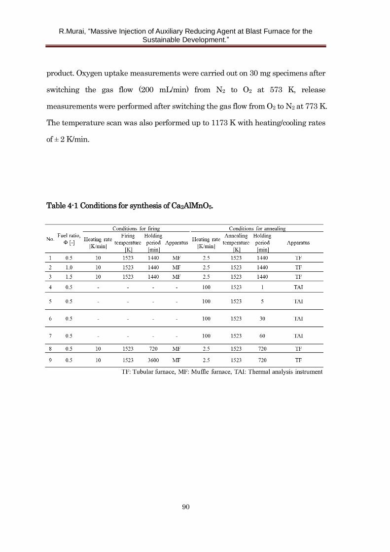
R.Murai, “Massive Injection of Auxiliary Reducing Agent at Blast Furnace for the
Sustainable Development.”
90
product. Oxygen uptake measurements were carried out on 30 mg specimens after
switching the gas flow (200 mL/min) from N2 to O2 at 573 K, release
measurements were performed after switching the gas flow from O2 to N2 at 773 K.
The temperature scan was also performed up to 1173 K with heating/cooling rates
of ± 2 K/min.
Table 4-1 Conditions for synthesis of Ca2AlMnO5.
R.Murai, “Massive Injection of Auxiliary Reducing Agent at Blast Furnace for the
Sustainable Development.”
91
4. 3 Results and Discussion
4. 3. 1 Effect of on the structure, morphology, and oxygen uptake and release
Fig. 4-1 shows the TG curve of the precursors from the SCS procedure, which were
obtained at different (0.5, 1.0, and 1.5). The measurements were performed in air
at a heating rate of 20 K/min. The total weight loss were found to be about 31 %,
16 %, and 26 % for the precursors obtained at = 0.5, 1.0, and 1.5 respectively. The
sample at = 1.0 showed the lowest weight loss and a remarkable weight loss
peak indicating an efficient combustion reaction between the glycine fuel and
nitrate oxidizers at near stoichiometric conditions. The weight loss at 923 – 1073 K
could be caused by the decomposition of CaCO3, formed during SCS. Because CaO
is generated by decomposition of Ca(NO3)2 during SCS, it would easily react with
CO2 from the oxidation of glycine to form the carbonate. It was expected that the
SCS-derived precursors would show greater weight changes at = 0.5 and 1.5,
because insufficient combustion reactions at the fuel-poor or rich conditions might
leave a large amount of unreacted glycine or nitrate residues. Although different
values produced different trends and total amounts of weight loss, all weight
changes were completed by about 1013 K for all samples. Therefore, we concluded
that the heat treatment temperature needed to form a stable product should be
higher than 1013 K.
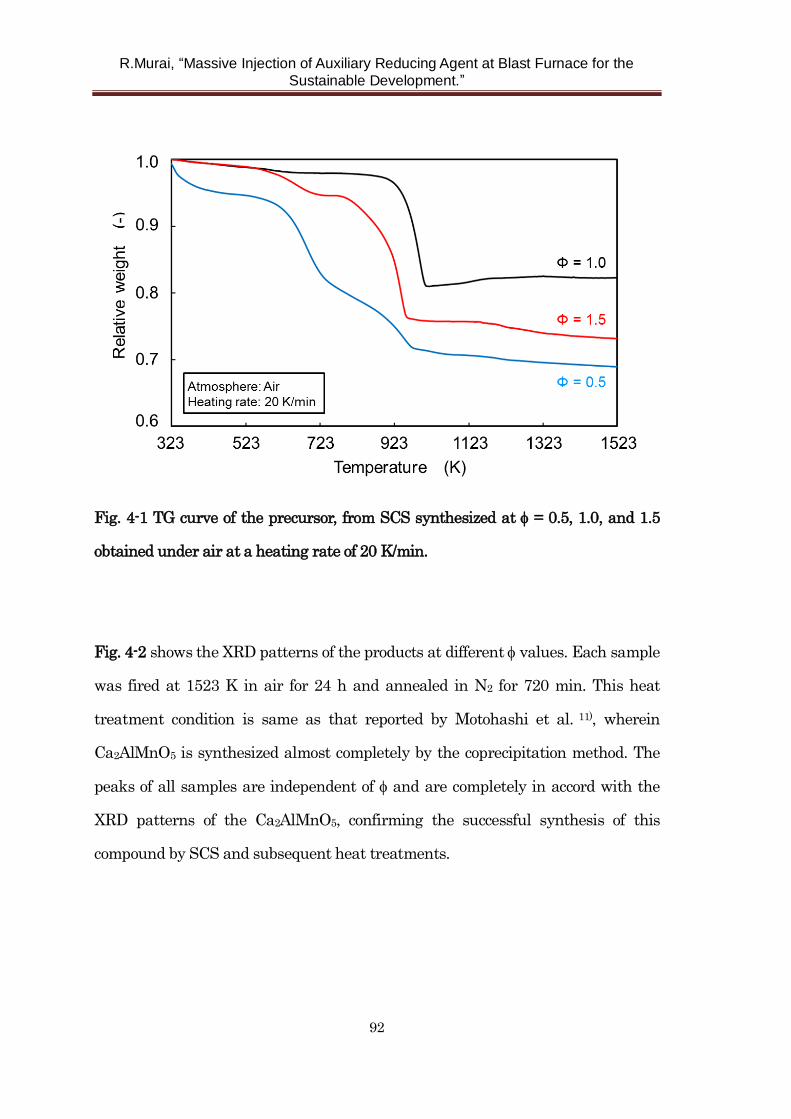
R.Murai, “Massive Injection of Auxiliary Reducing Agent at Blast Furnace for the
Sustainable Development.”
92
Fig. 4-1 TG curve of the precursor, from SCS synthesized at = 0.5, 1.0, and 1.5
obtained under air at a heating rate of 20 K/min.
Fig. 4-2 shows the XRD patterns of the products at different values. Each sample
was fired at 1523 K in air for 24 h and annealed in N2 for 720 min. This heat
treatment condition is same as that reported by Motohashi et al. 11), wherein
Ca2AlMnO5 is synthesized almost completely by the coprecipitation method. The
peaks of all samples are independent of and are completely in accord with the
XRD patterns of the Ca2AlMnO5, confirming the successful synthesis of this
compound by SCS and subsequent heat treatments.
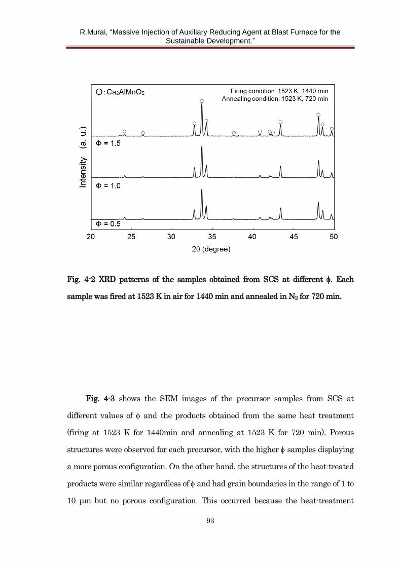
R.Murai, “Massive Injection of Auxiliary Reducing Agent at Blast Furnace for the
Sustainable Development.”
93
Fig. 4-2 XRD patterns of the samples obtained from SCS at different . Each
sample was fired at 1523 K in air for 1440 min and annealed in N2 for 720 min.
Fig. 4-3 shows the SEM images of the precursor samples from SCS at
different values of and the products obtained from the same heat treatment
(firing at 1523 K for 1440min and annealing at 1523 K for 720 min). Porous
structures were observed for each precursor, with the higher samples displaying
a more porous configuration. On the other hand, the structures of the heat-treated
products were similar regardless of and had grain boundaries in the range of 1 to
10 μm but no porous configuration. This occurred because the heat-treatment
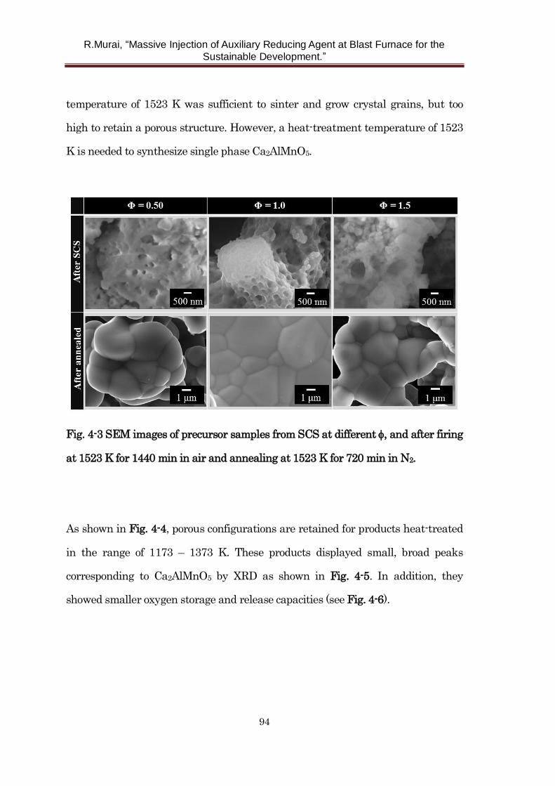
R.Murai, “Massive Injection of Auxiliary Reducing Agent at Blast Furnace for the
Sustainable Development.”
94
temperature of 1523 K was sufficient to sinter and grow crystal grains, but too
high to retain a porous structure. However, a heat-treatment temperature of 1523
K is needed to synthesize single phase Ca2AlMnO5.
Fig. 4-3 SEM images of precursor samples from SCS at different , and after firing
at 1523 K for 1440 min in air and annealing at 1523 K for 720 min in N2.
As shown in Fig. 4-4, porous configurations are retained for products heat-treated
in the range of 1173 – 1373 K. These products displayed small, broad peaks
corresponding to Ca2AlMnO5 by XRD as shown in Fig. 4-5. In addition, they
showed smaller oxygen storage and release capacities (see Fig. 4-6).
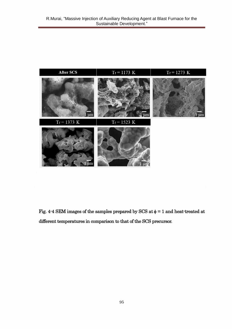
R.Murai, “Massive Injection of Auxiliary Reducing Agent at Blast Furnace for the
Sustainable Development.”
95
Fig. 4-4 SEM images of the samples prepared by SCS at = 1 and heat-treated at
different temperatures in comparison to that of the SCS precursor.
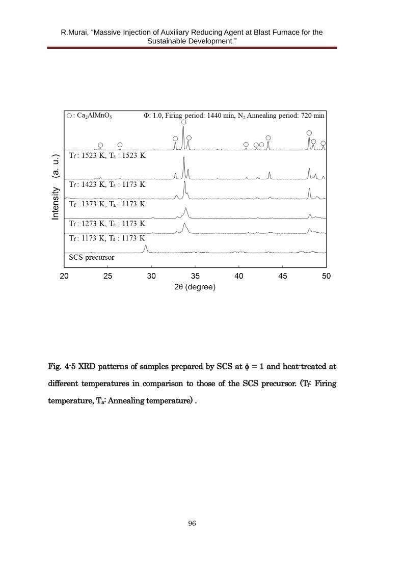
R.Murai, “Massive Injection of Auxiliary Reducing Agent at Blast Furnace for the
Sustainable Development.”
96
Fig. 4-5 XRD patterns of samples prepared by SCS at = 1 and heat-treated at
different temperatures in comparison to those of the SCS precursor. (Tf: Firing
temperature, Ta: Annealing temperature) .
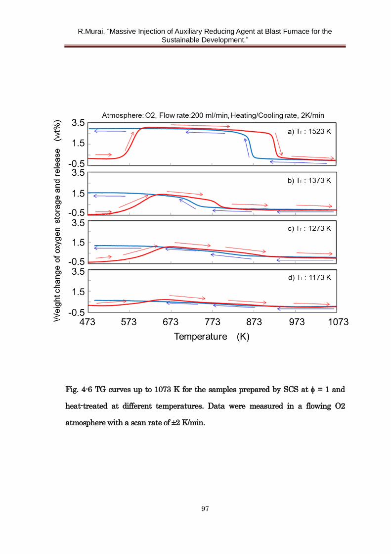
R.Murai, “Massive Injection of Auxiliary Reducing Agent at Blast Furnace for the
Sustainable Development.”
97
Fig. 4-6 TG curves up to 1073 K for the samples prepared by SCS at = 1 and
heat-treated at different temperatures. Data were measured in a flowing O2
atmosphere with a scan rate of ±2 K/min.
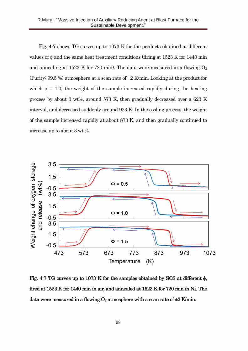
R.Murai, “Massive Injection of Auxiliary Reducing Agent at Blast Furnace for the
Sustainable Development.”
98
Fig. 4-7 shows TG curves up to 1073 K for the products obtained at different
values of and the same heat treatment conditions (firing at 1523 K for 1440 min
and annealing at 1523 K for 720 min). The data were measured in a flowing O2
(Purity: 99.5 %) atmosphere at a scan rate of ±2 K/min. Looking at the product for
which = 1.0, the weight of the sample increased rapidly during the heating
process by about 3 wt%, around 573 K, then gradually decreased over a 623 K
interval, and decreased suddenly around 923 K. In the cooling process, the weight
of the sample increased rapidly at about 873 K, and then gradually continued to
increase up to about 3 wt %.
Fig. 4-7 TG curves up to 1073 K for the samples obtained by SCS at different ,
fired at 1523 K for 1440 min in air, and annealed at 1523 K for 720 min in N2. The
data were measured in a flowing O2 atmosphere with a scan rate of ±2 K/min.
R.Murai, “Massive Injection of Auxiliary Reducing Agent at Blast Furnace for the
Sustainable Development.”
99
All products exhibited a similar pattern of oxygen-storage and release. The
reversible oxygen storage/release behavior of Ca2AlMnO5 is in good agreement
with the report of Motohashi et al. 11), in which Ca2AlMnO5 is synthesized almost
completely by a coprecipitation method. Our results show that SCS is an effective
new route to the synthesis of Ca2AlMnO5.
4. 3. 2 Effect of periods of heat-treatment
Fig. 4-8 shows the XRD patterns of the samples prepared by SCS at = 0.5,
and heat-treated for different lengths of time (1 – 4320 min) at 1523 K. All samples
showed clear evidence of Ca2AlMnO5. Interestingly, the sample with only 1 min
annealing (without firing) also showed a distinct Ca2AlMnO5 phase. This is a
much shorter heat-treatment period for Ca2AlMnO5 synthesis than that of other
methods such as coprecipitation and solid state reaction. Motohashi et al.
synthesized Ca2AlMnO5 by coprecipitation from nitrate salts and employed a
heat-treatment period of 36 h at 1523 K11). Wright et al. and Palmer et al.
synthesized Ca2AlMnO5 from carbonate and oxide powders by solid state reaction
at 1523 K for 48 h12,13). Therefore, the SCS affords the energy saving advantage of
rapid synthesis of high-purity Ca2AlMnO5. The formation of Ca2AlMnO5 by
annealing without firing showed that the precursors from SCS consisted of CaO,
Al2O3, Mn2O3 and that Ca2AlMnO5 was synthesized by the following reaction:
2CaO + 1/2 Al2O3 + 1/2 Mn2O3 → Ca2AlMnO5
(4-3)
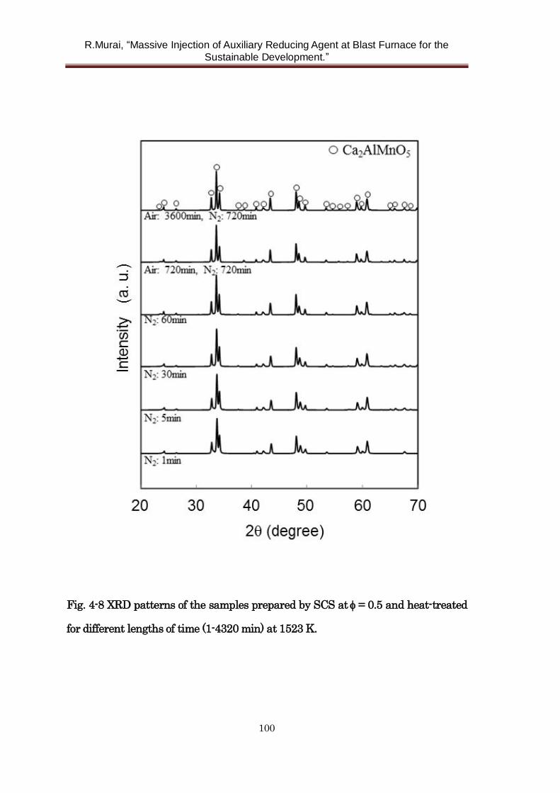
R.Murai, “Massive Injection of Auxiliary Reducing Agent at Blast Furnace for the
Sustainable Development.”
100
Fig. 4-8 XRD patterns of the samples prepared by SCS at= 0.5 and heat-treated
for different lengths of time (1-4320 min) at 1523 K.
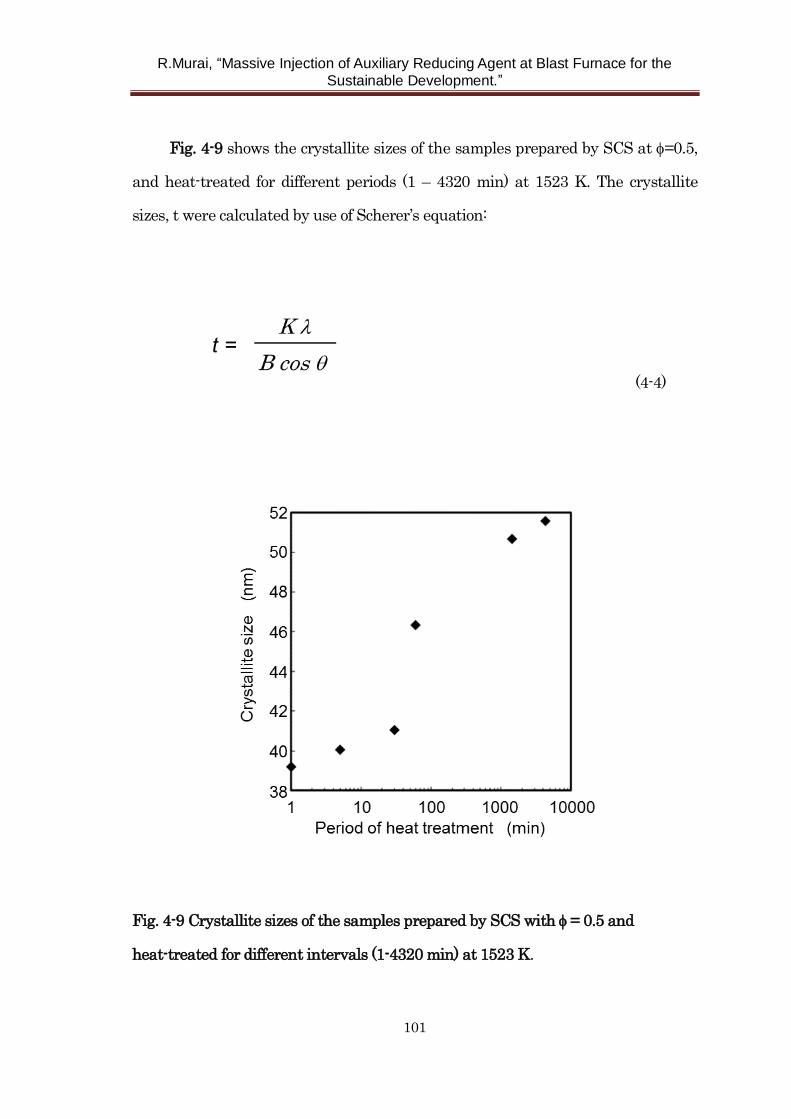
R.Murai, “Massive Injection of Auxiliary Reducing Agent at Blast Furnace for the
Sustainable Development.”
101
Fig. 4-9 shows the crystallite sizes of the samples prepared by SCS at =0.5,
and heat-treated for different periods (1 – 4320 min) at 1523 K. The crystallite
sizes, t were calculated by use of Scherer’s equation:
(4-4)
Fig. 4-9 Crystallite sizes of the samples prepared by SCS with = 0.5 and
heat-treated for different intervals (1-4320 min) at 1523 K.
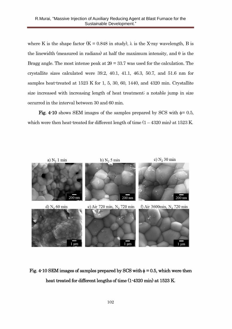
R.Murai, “Massive Injection of Auxiliary Reducing Agent at Blast Furnace for the
Sustainable Development.”
102
where K is the shape factor (K = 0.848 in study), is the X-ray wavelength, B is
the linewidth (measured in radians) at half the maximum intensity, and is the
Bragg angle. The most intense peak at 2 = 33.7 was used for the calculation. The
crystallite sizes calculated were 39.2, 40.1, 41.1, 46.3, 50.7, and 51.6 nm for
samples heat-treated at 1523 K for 1, 5, 30, 60, 1440, and 4320 min. Crystallite
size increased with increasing length of heat treatment; a notable jump in size
occurred in the interval between 30 and 60 min.
Fig. 4-10 shows SEM images of the samples prepared by SCS with = 0.5,
which were then heat-treated for different length of time (1 – 4320 min) at 1523 K.
Fig. 4-10 SEM images of samples prepared by SCS with = 0.5, which were then
heat treated for different lengths of time (1-4320 min) at 1523 K.
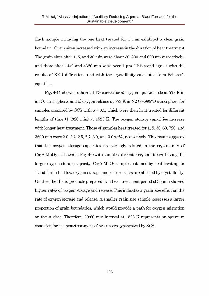
R.Murai, “Massive Injection of Auxiliary Reducing Agent at Blast Furnace for the
Sustainable Development.”
103
Each sample including the one heat treated for 1 min exhibited a clear grain
boundary. Grain sizes increased with an increase in the duration of heat treatment.
The grain sizes after 1, 5, and 30 min were about 30, 200 and 600 nm respectively,
and those after 1440 and 4320 min were over 1 μm. This trend agrees with the
results of XRD diffractions and with the crystallinity calculated from Scherer’s
equation.
Fig. 4-11 shows isothermal TG curves for a) oxygen uptake mode at 573 K in
an O2 atmosphere, and b) oxygen release at 773 K in N2 (99.999%) atmosphere for
samples prepared by SCS with = 0.5, which were then heat treated for different
lengths of time (1-4320 min) at 1523 K. The oxygen storage capacities increase
with longer heat treatment. Those of samples heat-treated for 1, 5, 30, 60, 720, and
3600 min were 2.0, 2.2, 2.5, 2.7, 3.0, and 3.0 wt%, respectively. This result suggests
that the oxygen storage capacities are strongly related to the crystallinity of
Ca2AlMnO5 as shown in Fig. 4-9 with samples of greater crystallite size having the
larger oxygen storage capacity. Ca2AlMnO5 samples obtained by heat treating for
1 and 5 min had low oxygen storage and release rates are affected by crystallinity.
On the other hand products prepared by a heat-treatment period of 30 min showed
higher rates of oxygen storage and release. This indicates a grain size effect on the
rate of oxygen storage and release. A smaller grain size sample possesses a larger
proportion of grain boundaries, which would provide a path for oxygen migration
on the surface. Therefore, 30-60 min interval at 1523 K represents an optimum
condition for the heat-treatment of precursors synthesized by SCS.
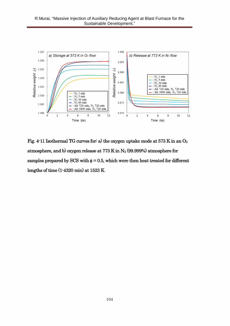
R.Murai, “Massive Injection of Auxiliary Reducing Agent at Blast Furnace for the
Sustainable Development.”
104
Fig. 4-11 Isothermal TG curves for: a) the oxygen uptake mode at 573 K in an O2
atmosphere, and b) oxygen release at 773 K in N2 (99.999%) atmosphere for
samples prepared by SCS with = 0.5, which were then heat treated for different
lengths of time (1-4320 min) at 1523 K.
R.Murai, “Massive Injection of Auxiliary Reducing Agent at Blast Furnace for the
Sustainable Development.”
105
4. 4 Conclusions
In summary, the high capacity oxygen storage material, Ca2AlMnO5, which
has applications in air-separation technology, was synthesized by
glycine-nitrate-based solution combustion synthesis. The effects of glycine content
and length of heat treatment on the structure, morphology, and oxygen
storage/release properties of the products were investigated to find optimized
production conditions. Single phase Ca2AlMnO5, whose maximum reversible
oxygen uptake and release amounts to about 3.0 wt%, was successfully
synthesized with various glycine contents. Single phase Ca2AlMnO5 can be
synthesized by combination of SCS and just 1 min of heat treatment at 1523 K.
Products prepared with longer periods of heat-treatment exhibited greater
crystallinity and larger reversible oxygen storage capacities. The present results
indicate that the glycine-nitrate SCS process is an attractive method for the
fabrication of Brownmillerite-type Ca2AlMnO5.
R.Murai, “Massive Injection of Auxiliary Reducing Agent at Blast Furnace for the
Sustainable Development.”
106
References
1) T. Motohashi, M. Kimura, T. Inayoshi, T. Ueda, Y. Masubuchi and S. Kikkawa:
Dalton Trans.,44(2015),10746.
2) Y. Kansha, A. Kishimoto, T. Nakagawa and A. Tsutsumi: Separation and
Purification Technology, 77(2011), 389.
3) N. D. Hutson, S. U. Rege and R. T. Yang: AIChE journal, 45(1999), 724.
4) K. Watanabe, N. Austin and M. Stapleton: Molecular Simulation, 15(1995), 197.
5) M. Hassan, D. Ruthven and N. Raghavan: Chemical Engineering Science,
41(1986), 1333.
6) Z. Yang, Y. Lin and Y. Zeng: Industrial & engineering chemistry research,
41(2002), 2775.
7) S. Kadota, M. Karppinen, T. Motohashi and H. Yamauchi: Chemistry of
Materials, 20(2008), 6378.
8) M. Karppinen, H. Yamauchi, S. Otani, T. Fujita, T. Motohashi, Y. H. Huang, et
al. : Chemistry of materials, 18(2006), 490.
9) T. Motohashi, S. Kadota, H. Fjellvåg, M. Karppinen and H. Yamauchi:
Materials Science and Engineering B, 148(2008), 196.
10) Y. He, X. Zhu and W. Yang: AIChE Journal, 57(2011), 87.
11) T. Motohashi, Y. Hirano, Y. Masubuchi, K. Oshima, T. Setoyama and S.
Kikkawa: Chemistry of Materials, 25(2013), 372.
12) H. M. Palmer, A. Snedden, A. J. Wright and C. Greaves: Chemistry of
materials, 18(2006), 1130.
13) A. Wright, H. Palmer, P. Anderson and C. Greaves: Journal of Materials
Chemistry, 12(2002), 978.
14) C. Zhu and T. Akiyama: Electrochimica Acta, 127(2014), 290.
R.Murai, “Massive Injection of Auxiliary Reducing Agent at Blast Furnace for the
Sustainable Development.”
107
15) L. A. Chick, L. Pederson, G. Maupin, J. Bates, L. Thomas and G. Exarhos:
Materials Letters, 10(1990), 6.
16) R. Epherre, E. Duguet, S. Mornet, E. Pollert, S. Louguet and S.
Lecommandoux, et al.: Journal of Materials Chemistry, 21(2011), 4393.
17) C. Zhu, A. Nobuta, Y. W. Ju, T. Ishihara and T. Akiyama: International
Journal of Hydrogen Energy, 38(2013), 13419.
18) C. Zhu, A. Nobuta, I. Nakatsugawa and T. Akiyama: International Journal of
Hydrogen Energy, 38(2013), 13238.
19) C. Zhu, A. Nobuta, G. Saito, I. Nakatsugawa and T. Akiyama: Advanced
Powder Technology, 25(2013), 342.
R.Murai, “Massive Injection of Auxiliary Reducing Agent at Blast Furnace for the
Sustainable Development.”
108
Chapter 5 Development of new cooling system to increase
injection amount of auxiliary reducing agent to blast furnace
5.1 Introduction
Life time prolongation of blast furnace has been one of the most important
issues to avoid considerable investment cost in the iron making process. Life time
of a blast furnace is usually determined by the deformation or damage of cooling
staves (CS) as well as wear of bottom brick because they are difficult to repair
during campaign. Injection of auxiliary reducing agent such as pulverized coal and
used plastics has been expanding year by year. However, it has been pointed out
that strengthen of peripheral gas flow leads to increase in the heat load to wall of
furnace due to the change in the permeability of lower part of blast furnace 1,2).
Considering the need for increase in the injection amount of auxiliary reducing
agent, development of new long life CS is so important to cope with change of the
in-furnace situations.
It has been reported that CS made with copper instead of conventional cast
iron has been used to enhance the durability of the bosh part3-8). Basically, many of
them are only a study of general evaluation to the operational conditions at
particular blast furnace, and there are few reports regarding thermal and
mechanical characteristics and mechanism of wearing of copper CS considering
above mentioned in-furnace situation such as high rate injection of pulverized coal.
Rolled copper has been used as material of copper CS. However, cast copper
has excellent features such as good workability (castability) and lower production
cost to make CS. In this chapter, characteristics of CS made with cast iron, rolled
copper, and cast copper are evaluated by the numerical simulation of heat transfer
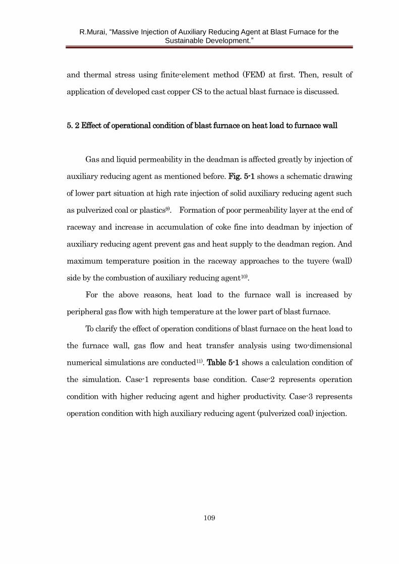
R.Murai, “Massive Injection of Auxiliary Reducing Agent at Blast Furnace for the
Sustainable Development.”
109
and thermal stress using finite-element method (FEM) at first. Then, result of
application of developed cast copper CS to the actual blast furnace is discussed.
5. 2 Effect of operational condition of blast furnace on heat load to furnace wall
Gas and liquid permeability in the deadman is affected greatly by injection of
auxiliary reducing agent as mentioned before. Fig. 5-1 shows a schematic drawing
of lower part situation at high rate injection of solid auxiliary reducing agent such
as pulverized coal or plastics9). Formation of poor permeability layer at the end of
raceway and increase in accumulation of coke fine into deadman by injection of
auxiliary reducing agent prevent gas and heat supply to the deadman region. And
maximum temperature position in the raceway approaches to the tuyere (wall)
side by the combustion of auxiliary reducing agent10).
For the above reasons, heat load to the furnace wall is increased by
peripheral gas flow with high temperature at the lower part of blast furnace.
To clarify the effect of operation conditions of blast furnace on the heat load to
the furnace wall, gas flow and heat transfer analysis using two-dimensional
numerical simulations are conducted11). Table 5-1 shows a calculation condition of
the simulation. Case-1 represents base condition. Case-2 represents operation
condition with higher reducing agent and higher productivity. Case-3 represents
operation condition with high auxiliary reducing agent (pulverized coal) injection.
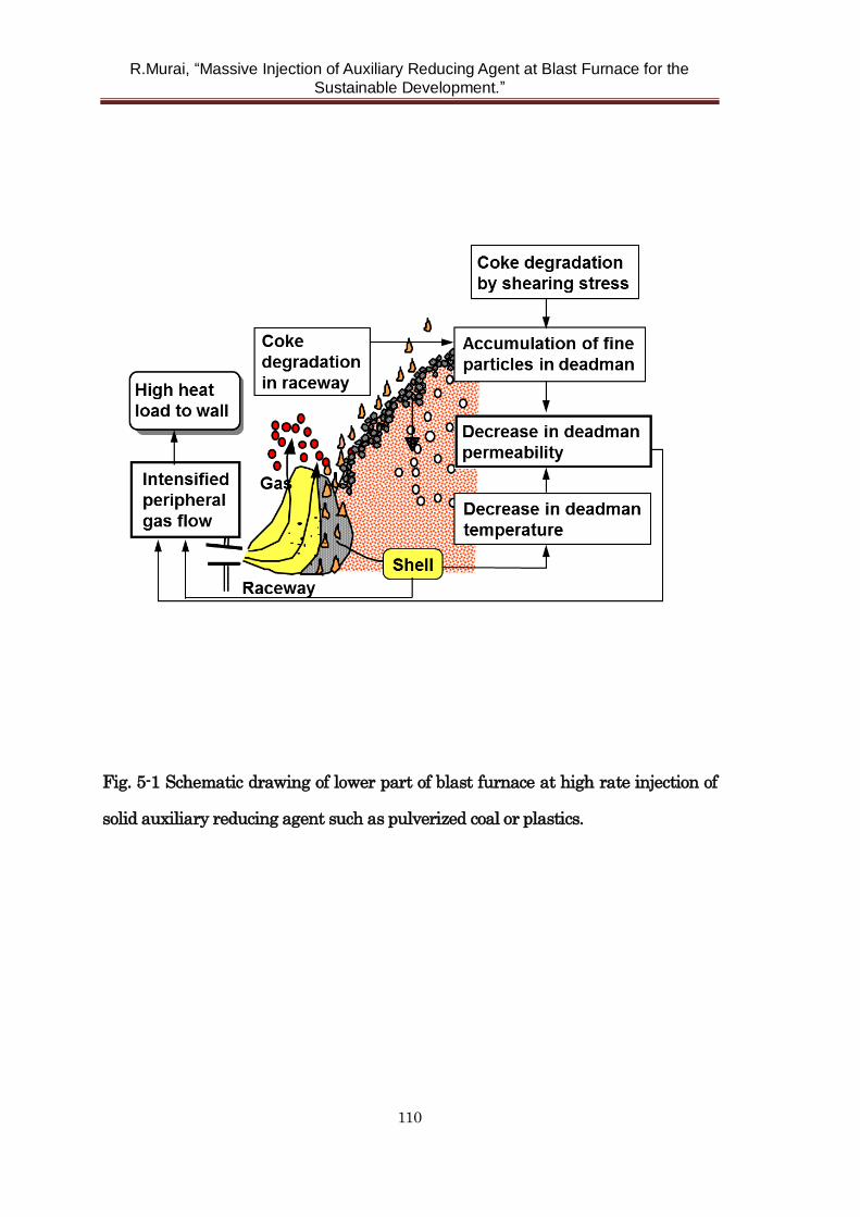
R.Murai, “Massive Injection of Auxiliary Reducing Agent at Blast Furnace for the
Sustainable Development.”
110
Fig. 5-1 Schematic drawing of lower part of blast furnace at high rate injection of
solid auxiliary reducing agent such as pulverized coal or plastics.
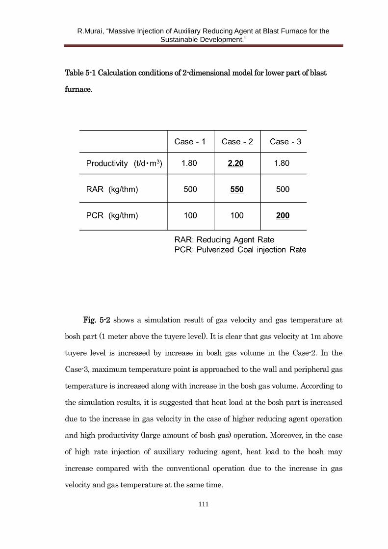
R.Murai, “Massive Injection of Auxiliary Reducing Agent at Blast Furnace for the
Sustainable Development.”
111
Table 5-1 Calculation conditions of 2-dimensional model for lower part of blast
furnace.
Fig. 5-2 shows a simulation result of gas velocity and gas temperature at
bosh part (1 meter above the tuyere level). It is clear that gas velocity at 1m above
tuyere level is increased by increase in bosh gas volume in the Case-2. In the
Case-3, maximum temperature point is approached to the wall and peripheral gas
temperature is increased along with increase in the bosh gas volume. According to
the simulation results, it is suggested that heat load at the bosh part is increased
due to the increase in gas velocity in the case of higher reducing agent operation
and high productivity (large amount of bosh gas) operation. Moreover, in the case
of high rate injection of auxiliary reducing agent, heat load to the bosh may
increase compared with the conventional operation due to the increase in gas
velocity and gas temperature at the same time.
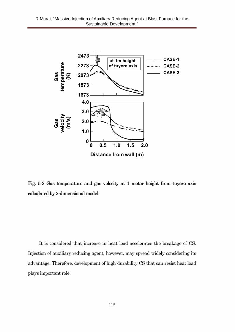
R.Murai, “Massive Injection of Auxiliary Reducing Agent at Blast Furnace for the
Sustainable Development.”
112
Fig. 5-2 Gas temperature and gas velocity at 1 meter height from tuyere axis
calculated by 2-dimensional model.
It is considered that increase in heat load accelerates the breakage of CS.
Injection of auxiliary reducing agent, however, may spread widely considering its
advantage. Therefore, development of high-durability CS that can resist heat load
plays important role.
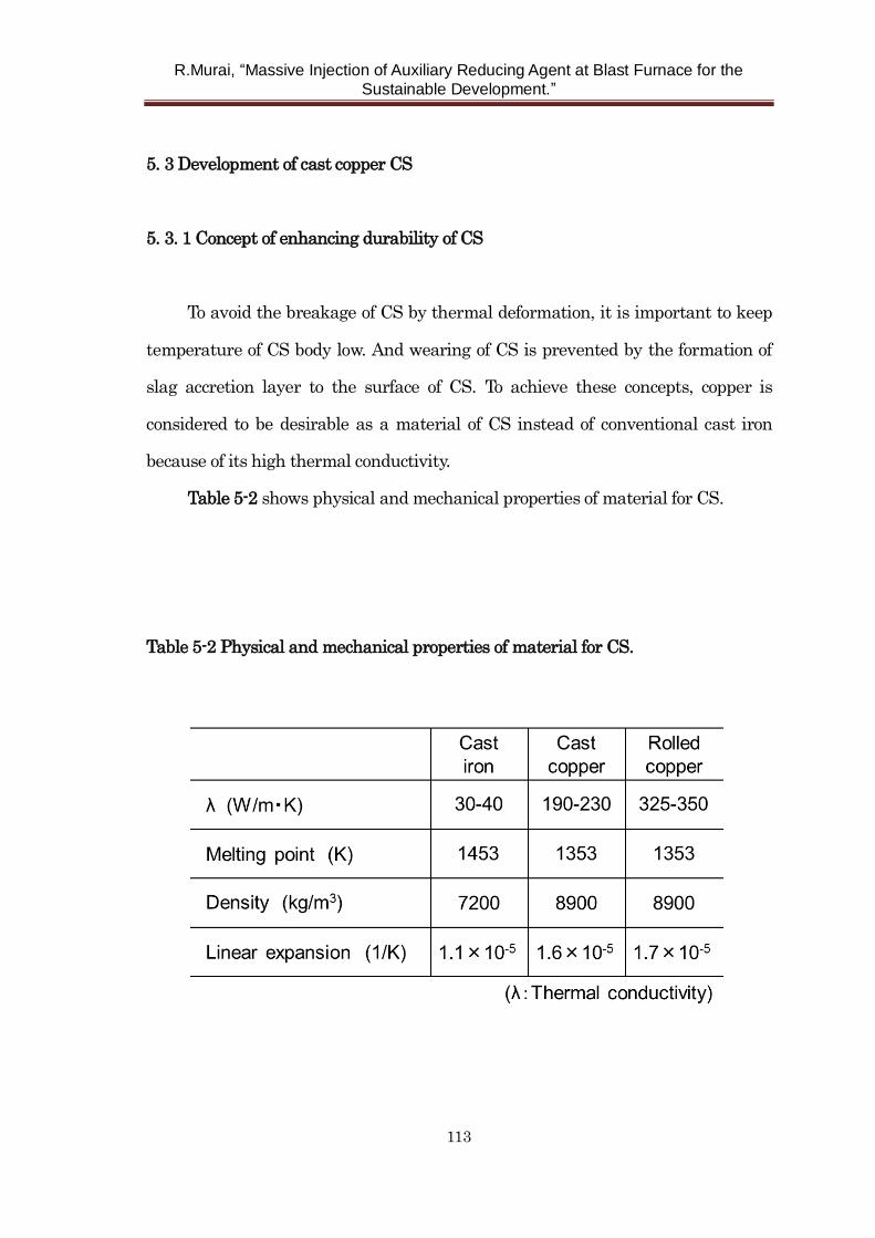
R.Murai, “Massive Injection of Auxiliary Reducing Agent at Blast Furnace for the
Sustainable Development.”
113
5. 3 Development of cast copper CS
5. 3. 1 Concept of enhancing durability of CS
To avoid the breakage of CS by thermal deformation, it is important to keep
temperature of CS body low. And wearing of CS is prevented by the formation of
slag accretion layer to the surface of CS. To achieve these concepts, copper is
considered to be desirable as a material of CS instead of conventional cast iron
because of its high thermal conductivity.
Table 5-2 shows physical and mechanical properties of material for CS.
Table 5-2 Physical and mechanical properties of material for CS.
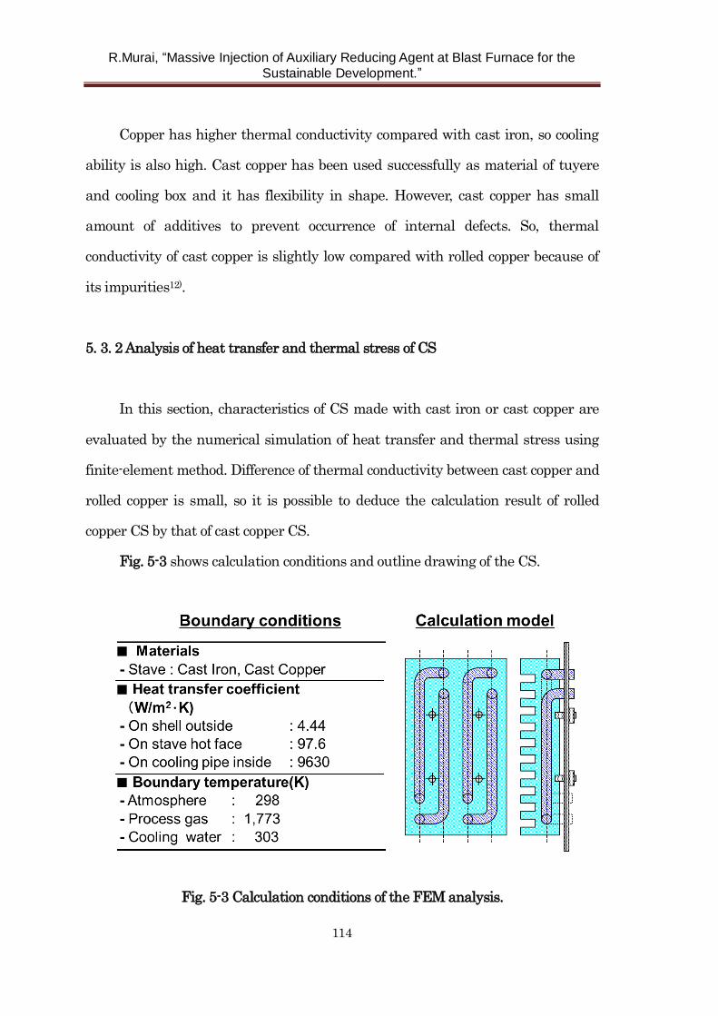
R.Murai, “Massive Injection of Auxiliary Reducing Agent at Blast Furnace for the
Sustainable Development.”
114
Copper has higher thermal conductivity compared with cast iron, so cooling
ability is also high. Cast copper has been used successfully as material of tuyere
and cooling box and it has flexibility in shape. However, cast copper has small
amount of additives to prevent occurrence of internal defects. So, thermal
conductivity of cast copper is slightly low compared with rolled copper because of
its impurities12).
5. 3. 2 Analysis of heat transfer and thermal stress of CS
In this section, characteristics of CS made with cast iron or cast copper are
evaluated by the numerical simulation of heat transfer and thermal stress using
finite-element method. Difference of thermal conductivity between cast copper and
rolled copper is small, so it is possible to deduce the calculation result of rolled
copper CS by that of cast copper CS.
Fig. 5-3 shows calculation conditions and outline drawing of the CS.
Fig. 5-3 Calculation conditions of the FEM analysis.
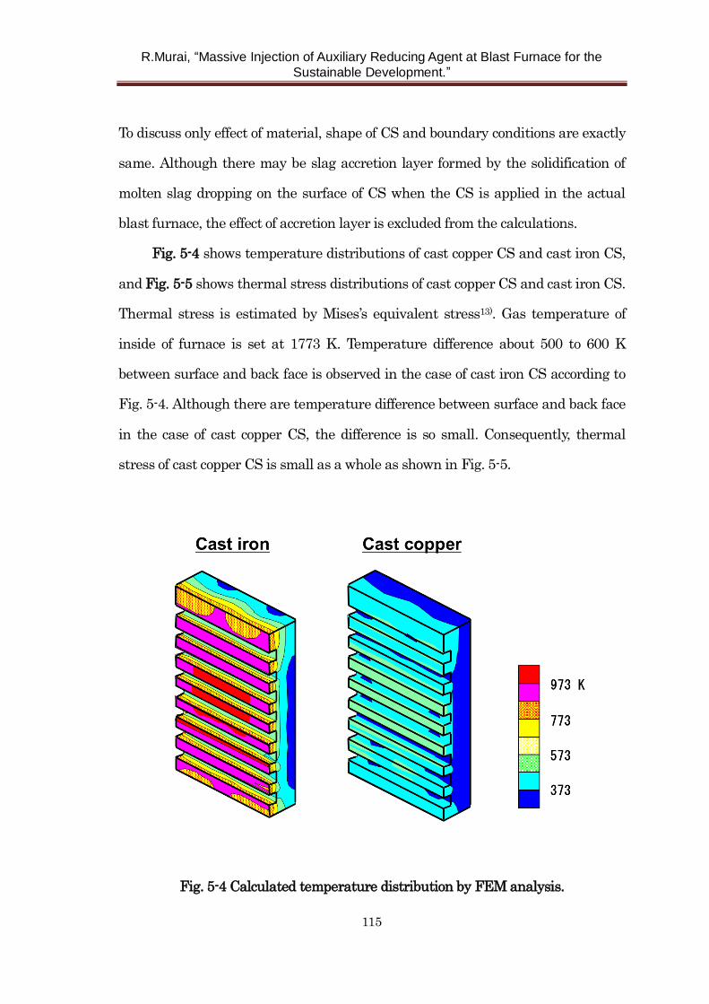
R.Murai, “Massive Injection of Auxiliary Reducing Agent at Blast Furnace for the
Sustainable Development.”
115
To discuss only effect of material, shape of CS and boundary conditions are exactly
same. Although there may be slag accretion layer formed by the solidification of
molten slag dropping on the surface of CS when the CS is applied in the actual
blast furnace, the effect of accretion layer is excluded from the calculations.
Fig. 5-4 shows temperature distributions of cast copper CS and cast iron CS,
and Fig. 5-5 shows thermal stress distributions of cast copper CS and cast iron CS.
Thermal stress is estimated by Mises’s equivalent stress13). Gas temperature of
inside of furnace is set at 1773 K. Temperature difference about 500 to 600 K
between surface and back face is observed in the case of cast iron CS according to
Fig. 5-4. Although there are temperature difference between surface and back face
in the case of cast copper CS, the difference is so small. Consequently, thermal
stress of cast copper CS is small as a whole as shown in Fig. 5-5.
Fig. 5-4 Calculated temperature distribution by FEM analysis.
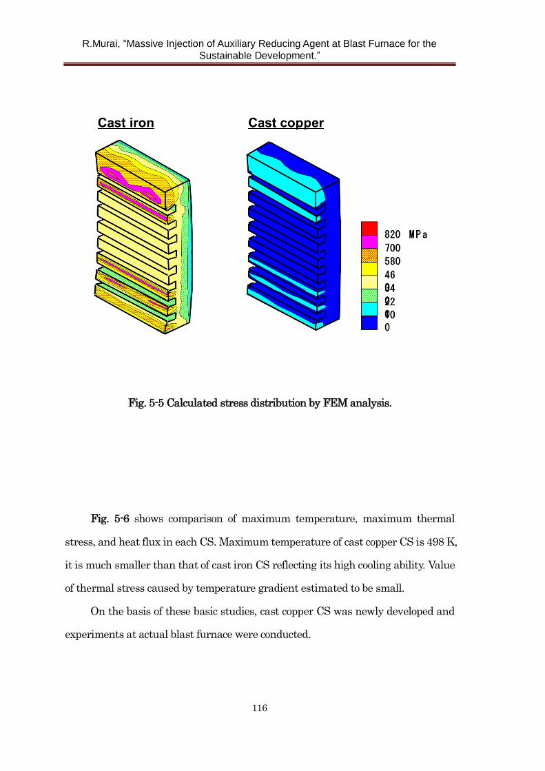
R.Murai, “Massive Injection of Auxiliary Reducing Agent at Blast Furnace for the
Sustainable Development.”
116
Fig. 5-5 Calculated stress distribution by FEM analysis.
Fig. 5-6 shows comparison of maximum temperature, maximum thermal
stress, and heat flux in each CS. Maximum temperature of cast copper CS is 498 K,
it is much smaller than that of cast iron CS reflecting its high cooling ability. Value
of thermal stress caused by temperature gradient estimated to be small.
On the basis of these basic studies, cast copper CS was newly developed and
experiments at actual blast furnace were conducted.
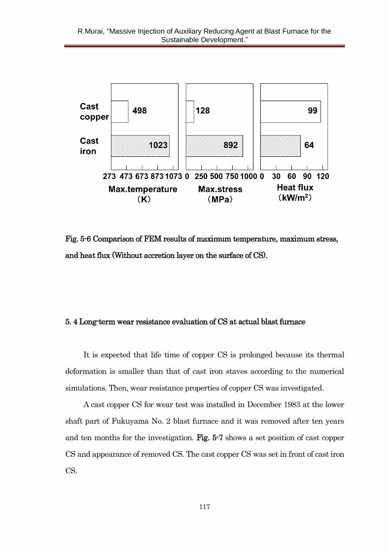
R.Murai, “Massive Injection of Auxiliary Reducing Agent at Blast Furnace for the
Sustainable Development.”
117
Fig. 5-6 Comparison of FEM results of maximum temperature, maximum stress,
and heat flux (Without accretion layer on the surface of CS).
5. 4 Long-term wear resistance evaluation of CS at actual blast furnace
It is expected that life time of copper CS is prolonged because its thermal
deformation is smaller than that of cast iron staves according to the numerical
simulations. Then, wear resistance properties of copper CS was investigated.
A cast copper CS for wear test was installed in December 1983 at the lower
shaft part of Fukuyama No. 2 blast furnace and it was removed after ten years
and ten months for the investigation. Fig. 5-7 shows a set position of cast copper
CS and appearance of removed CS. The cast copper CS was set in front of cast iron
CS.
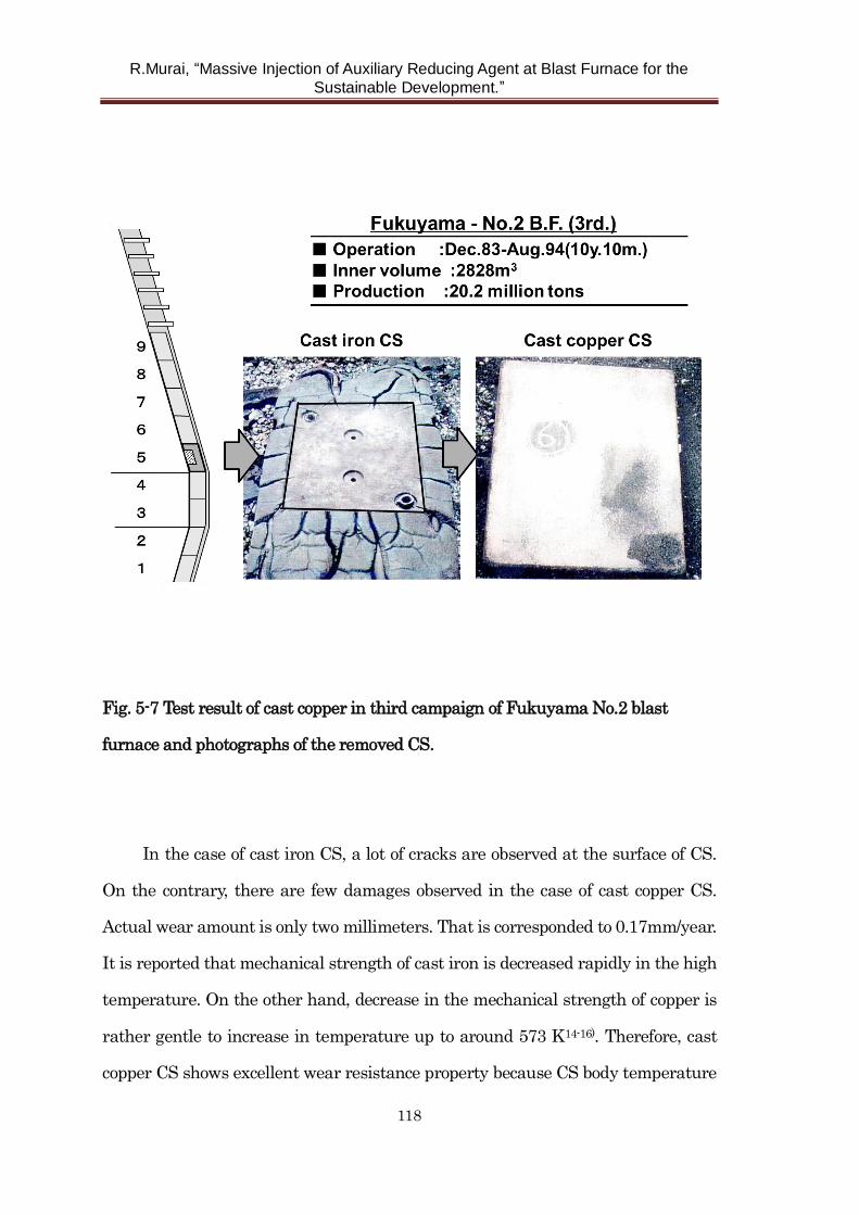
R.Murai, “Massive Injection of Auxiliary Reducing Agent at Blast Furnace for the
Sustainable Development.”
118
Fig. 5-7 Test result of cast copper in third campaign of Fukuyama No.2 blast
furnace and photographs of the removed CS.
In the case of cast iron CS, a lot of cracks are observed at the surface of CS.
On the contrary, there are few damages observed in the case of cast copper CS.
Actual wear amount is only two millimeters. That is corresponded to 0.17mm/year.
It is reported that mechanical strength of cast iron is decreased rapidly in the high
temperature. On the other hand, decrease in the mechanical strength of copper is
rather gentle to increase in temperature up to around 573 K14-16). Therefore, cast
copper CS shows excellent wear resistance property because CS body temperature
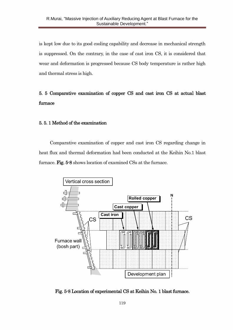
R.Murai, “Massive Injection of Auxiliary Reducing Agent at Blast Furnace for the
Sustainable Development.”
119
is kept low due to its good cooling capability and decrease in mechanical strength
is suppressed. On the contrary, in the case of cast iron CS, it is considered that
wear and deformation is progressed because CS body temperature is rather high
and thermal stress is high.
5. 5 Comparative examination of copper CS and cast iron CS at actual blast
furnace
5. 5. 1 Method of the examination
Comparative examination of copper and cast iron CS regarding change in
heat flux and thermal deformation had been conducted at the Keihin No.1 blast
furnace. Fig. 5-8 shows location of examined CSs at the furnace.
Fig. 5-8 Location of experimental CS at Keihin No. 1 blast furnace.
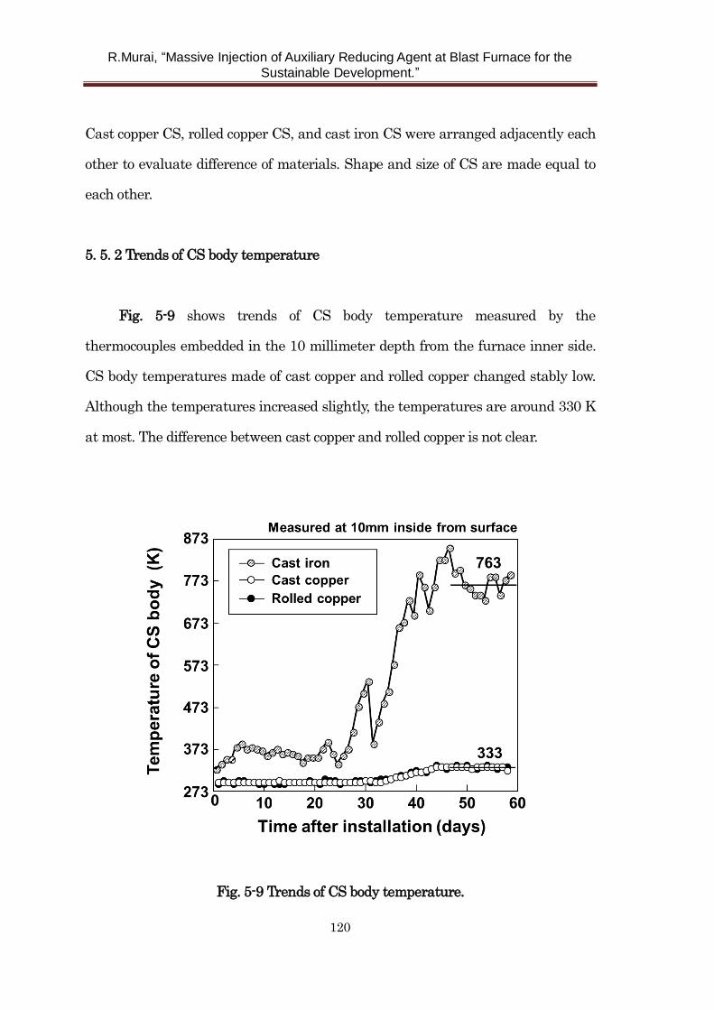
R.Murai, “Massive Injection of Auxiliary Reducing Agent at Blast Furnace for the
Sustainable Development.”
120
Cast copper CS, rolled copper CS, and cast iron CS were arranged adjacently each
other to evaluate difference of materials. Shape and size of CS are made equal to
each other.
5. 5. 2 Trends of CS body temperature
Fig. 5-9 shows trends of CS body temperature measured by the
thermocouples embedded in the 10 millimeter depth from the furnace inner side.
CS body temperatures made of cast copper and rolled copper changed stably low.
Although the temperatures increased slightly, the temperatures are around 330 K
at most. The difference between cast copper and rolled copper is not clear.
Fig. 5-9 Trends of CS body temperature.
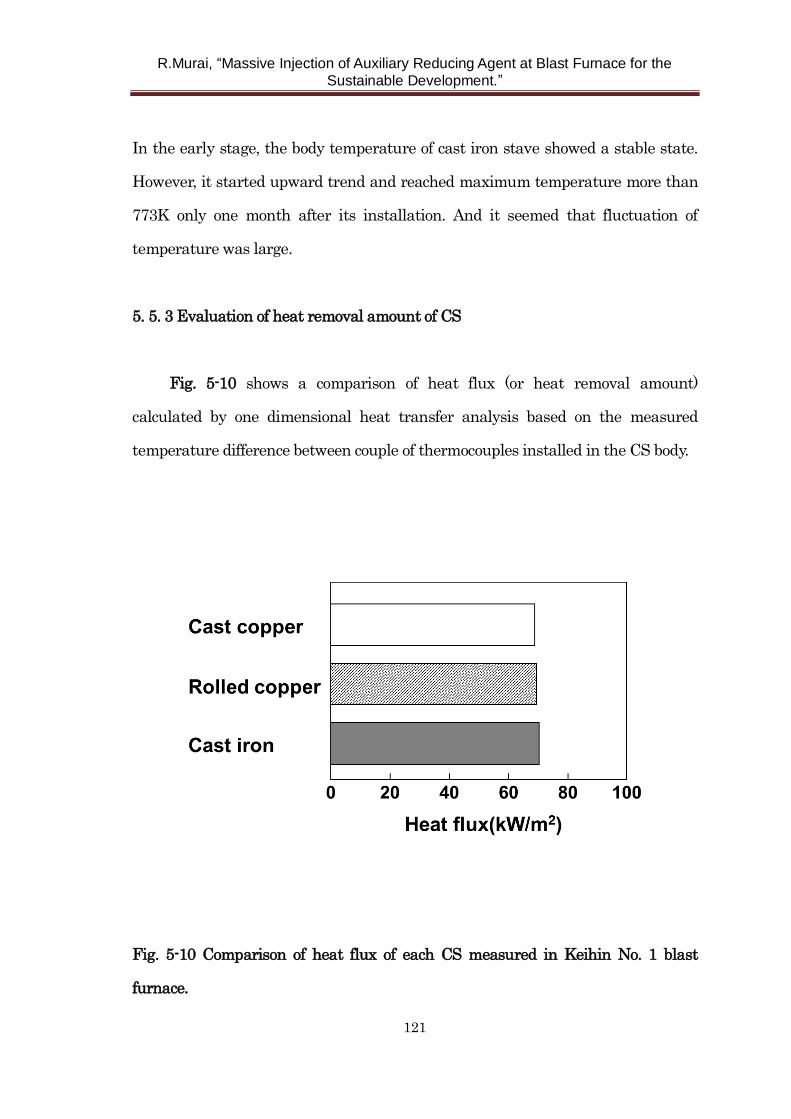
R.Murai, “Massive Injection of Auxiliary Reducing Agent at Blast Furnace for the
Sustainable Development.”
121
In the early stage, the body temperature of cast iron stave showed a stable state.
However, it started upward trend and reached maximum temperature more than
773K only one month after its installation. And it seemed that fluctuation of
temperature was large.
5. 5. 3 Evaluation of heat removal amount of CS
Fig. 5-10 shows a comparison of heat flux (or heat removal amount)
calculated by one dimensional heat transfer analysis based on the measured
temperature difference between couple of thermocouples installed in the CS body.
Fig. 5-10 Comparison of heat flux of each CS measured in Keihin No. 1 blast
furnace.
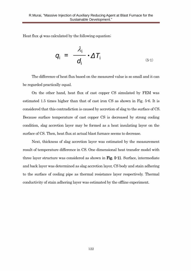
R.Murai, “Massive Injection of Auxiliary Reducing Agent at Blast Furnace for the
Sustainable Development.”
122
Heat flux qi was calculated by the following equation;
(5-1)
The difference of heat flux based on the measured value is so small and it can
be regarded practically equal.
On the other hand, heat flux of cast copper CS simulated by FEM was
estimated 1.5 times higher than that of cast iron CS as shown in Fig. 5-6. It is
considered that this contradiction is caused by accretion of slag to the surface of CS.
Because surface temperature of cast copper CS is decreased by strong cooling
condition, slag accretion layer may be formed as a heat insulating layer on the
surface of CS. Then, heat flux at actual blast furnace seems to decrease.
Next, thickness of slag accretion layer was estimated by the measurement
result of temperature difference in CS. One dimensional heat transfer model with
three layer structure was considered as shown in Fig. 5-11. Surface, intermediate
and back layer was determined as slag accretion layer, CS body and stain adhering
to the surface of cooling pipe as thermal resistance layer respectively. Thermal
conductivity of stain adhering layer was estimated by the offline experiment.
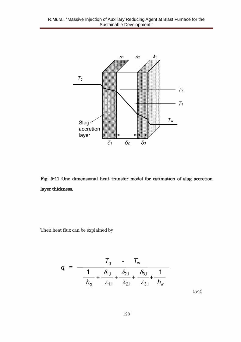
R.Murai, “Massive Injection of Auxiliary Reducing Agent at Blast Furnace for the
Sustainable Development.”
123
Fig. 5-11 One dimensional heat transfer model for estimation of slag accretion
layer thickness.
Then heat flux can be explained by
(5-2)
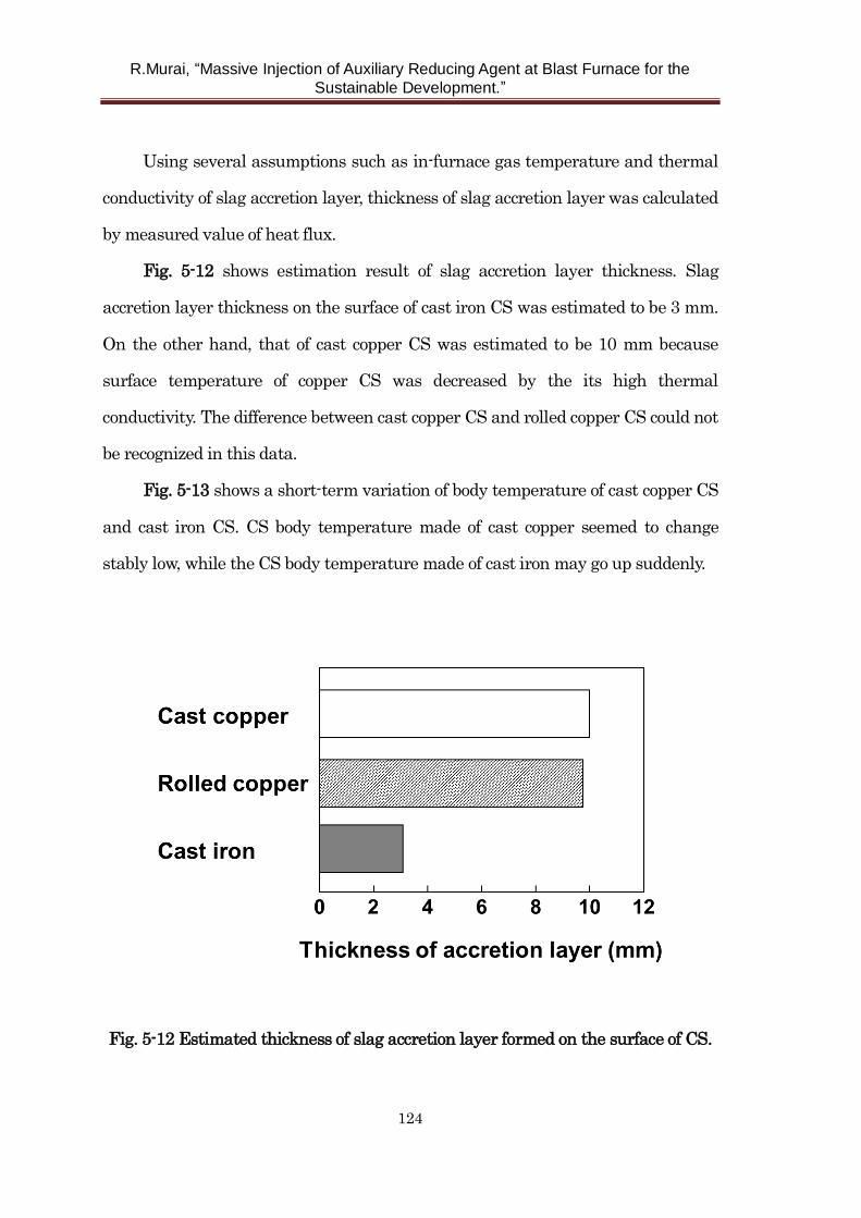
R.Murai, “Massive Injection of Auxiliary Reducing Agent at Blast Furnace for the
Sustainable Development.”
124
Using several assumptions such as in-furnace gas temperature and thermal
conductivity of slag accretion layer, thickness of slag accretion layer was calculated
by measured value of heat flux.
Fig. 5-12 shows estimation result of slag accretion layer thickness. Slag
accretion layer thickness on the surface of cast iron CS was estimated to be 3 mm.
On the other hand, that of cast copper CS was estimated to be 10 mm because
surface temperature of copper CS was decreased by the its high thermal
conductivity. The difference between cast copper CS and rolled copper CS could not
be recognized in this data.
Fig. 5-13 shows a short-term variation of body temperature of cast copper CS
and cast iron CS. CS body temperature made of cast copper seemed to change
stably low, while the CS body temperature made of cast iron may go up suddenly.
Fig. 5-12 Estimated thickness of slag accretion layer formed on the surface of CS.
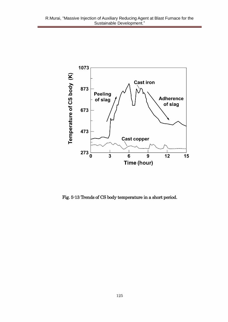
R.Murai, “Massive Injection of Auxiliary Reducing Agent at Blast Furnace for the
Sustainable Development.”
125
Fig. 5-13 Trends of CS body temperature in a short period.
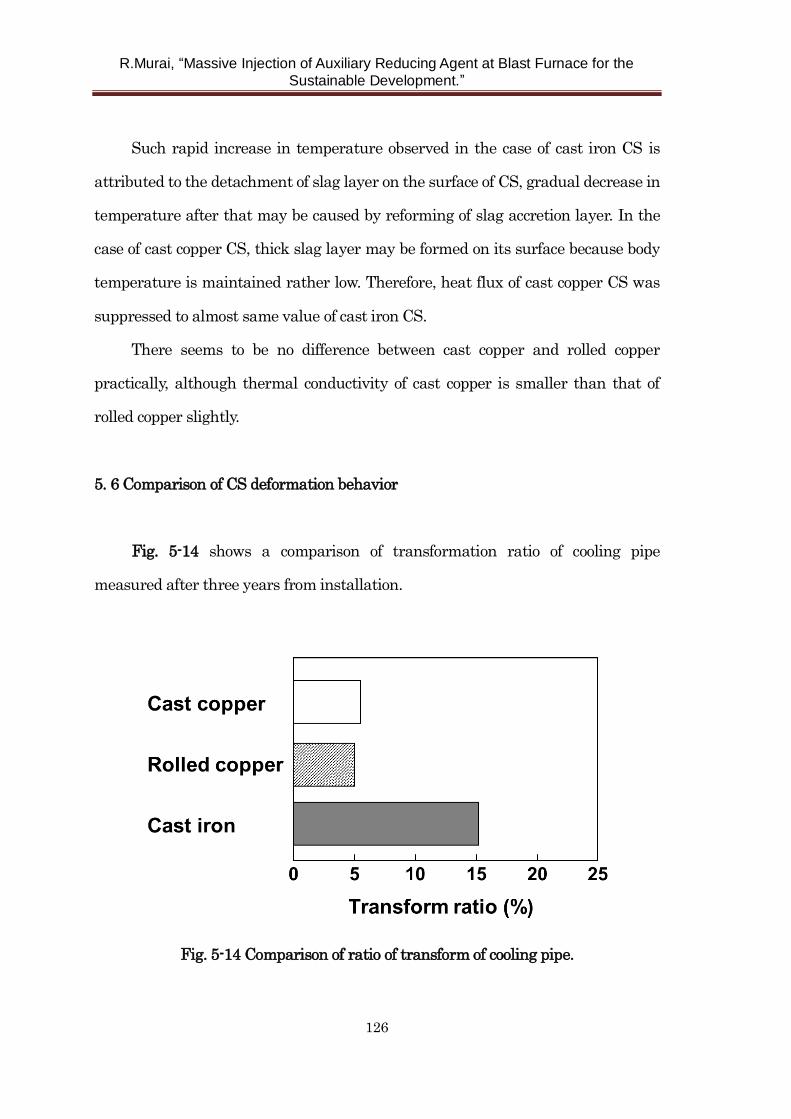
R.Murai, “Massive Injection of Auxiliary Reducing Agent at Blast Furnace for the
Sustainable Development.”
126
Such rapid increase in temperature observed in the case of cast iron CS is
attributed to the detachment of slag layer on the surface of CS, gradual decrease in
temperature after that may be caused by reforming of slag accretion layer. In the
case of cast copper CS, thick slag layer may be formed on its surface because body
temperature is maintained rather low. Therefore, heat flux of cast copper CS was
suppressed to almost same value of cast iron CS.
There seems to be no difference between cast copper and rolled copper
practically, although thermal conductivity of cast copper is smaller than that of
rolled copper slightly.
5. 6 Comparison of CS deformation behavior
Fig. 5-14 shows a comparison of transformation ratio of cooling pipe
measured after three years from installation.
Fig. 5-14 Comparison of ratio of transform of cooling pipe.
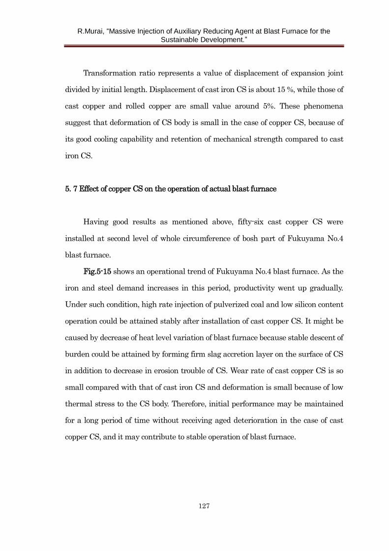
R.Murai, “Massive Injection of Auxiliary Reducing Agent at Blast Furnace for the
Sustainable Development.”
127
Transformation ratio represents a value of displacement of expansion joint
divided by initial length. Displacement of cast iron CS is about 15 %, while those of
cast copper and rolled copper are small value around 5%. These phenomena
suggest that deformation of CS body is small in the case of copper CS, because of
its good cooling capability and retention of mechanical strength compared to cast
iron CS.
5. 7 Effect of copper CS on the operation of actual blast furnace
Having good results as mentioned above, fifty-six cast copper CS were
installed at second level of whole circumference of bosh part of Fukuyama No.4
blast furnace.
Fig.5-15 shows an operational trend of Fukuyama No.4 blast furnace. As the
iron and steel demand increases in this period, productivity went up gradually.
Under such condition, high rate injection of pulverized coal and low silicon content
operation could be attained stably after installation of cast copper CS. It might be
caused by decrease of heat level variation of blast furnace because stable descent of
burden could be attained by forming firm slag accretion layer on the surface of CS
in addition to decrease in erosion trouble of CS. Wear rate of cast copper CS is so
small compared with that of cast iron CS and deformation is small because of low
thermal stress to the CS body. Therefore, initial performance may be maintained
for a long period of time without receiving aged deterioration in the case of cast
copper CS, and it may contribute to stable operation of blast furnace.
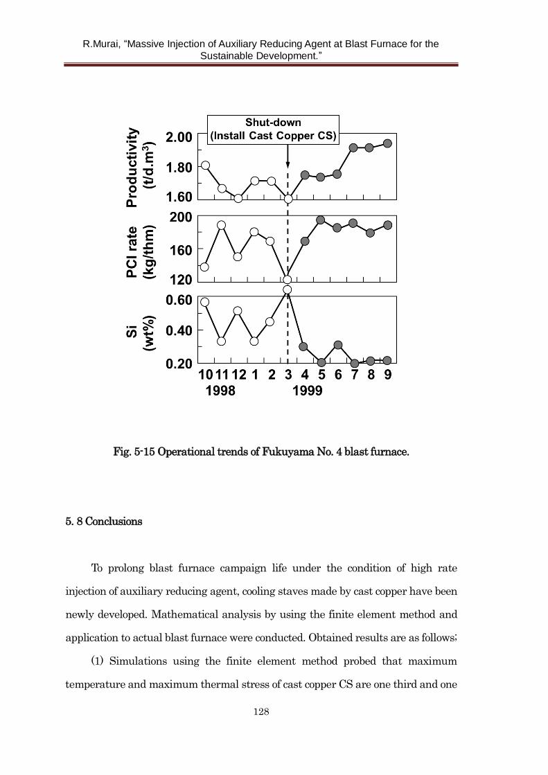
R.Murai, “Massive Injection of Auxiliary Reducing Agent at Blast Furnace for the
Sustainable Development.”
128
Fig. 5-15 Operational trends of Fukuyama No. 4 blast furnace.
5. 8 Conclusions
To prolong blast furnace campaign life under the condition of high rate
injection of auxiliary reducing agent, cooling staves made by cast copper have been
newly developed. Mathematical analysis by using the finite element method and
application to actual blast furnace were conducted. Obtained results are as follows;
(1) Simulations using the finite element method probed that maximum
temperature and maximum thermal stress of cast copper CS are one third and one
R.Murai, “Massive Injection of Auxiliary Reducing Agent at Blast Furnace for the
Sustainable Development.”
129
sixth level compared with conventional cast iron CS respectively because of its
high thermal conductivity, or high cooling capacity.
(2) Slag accretion layer seems to be formed on the surface of CS of cast copper
staves judging from the measurement results of CS body temperature at actual
blast furnace. Therefore, heat flux of cast copper stave is estimated as same level
as that of conventional cast iron CS. Deformation and wear rate of cast copper CS
is so small.
(3) Although thermal conductivity of cast copper CS is slightly inferior to that
of rolled copper CS, application result at actual blast furnace showed that cooling
capabilities of both CS were approximately same. Considering the flexibility and
processability of cast copper, cast copper may be superior to rolled copper as a raw
material of CS.
(4) Operation of actual blast furnace turned stably by the decrease in erosion
trouble of CS after using cast copper CS to whole circumference of bosh part.
Decrease in fluctuation of heat level may contribute to maintain of low silicon
operation owing to formation of stable, thick slag accretion layer on the surface of
CS.
(5) It is considered that cast copper CS is so effective to prolong blast furnace
campaign life operating with injection of massive auxiliary reducing agent such as
pulverized coal because of its enough cooling capacity to cope with increase in the
heat load to the lower part of blast furnace.
R.Murai, “Massive Injection of Auxiliary Reducing Agent at Blast Furnace for the
Sustainable Development.”
130
Nomenclature
q: heat flux (W/m2)
λ : thermal conductivity(W/m・K)
d: depth difference of thermocouples (m)
T: Temperature (K)
⊿T: temperature difference of thermocouples (K)
δ:thickness (m)
h: heat transfer coefficient (W/m2・K),
subscripts
i: cast iron, cast copper, rolled copper
1: slag
2: CS
3: stain adhering layer on the surface of cooling pipe
R.Murai, “Massive Injection of Auxiliary Reducing Agent at Blast Furnace for the
Sustainable Development.”
131
References
1) T.Kamijo, N.Takahashi, K.Hoshino, Y.Yoshida, R.Ito, K.Shibata and
Y.Miyakawa: CAMP-ISIJ, 6(1993),848
2) K.Mori, K.Tomioka, A.Shimomura, A.Sakai, K.Kimura and A.Maki: CAMP-ISIJ,
8(1995),960
3) H.Peter, H.Hille, H.J.Bachofen and W.Kowalski: Iron and Steel Engineer,
69(1992),49
4) H.Hille: Metallurgical Plant Technology International, 15(1992),38
5) W.R.Hathaway, K.S. Nanavati, D.H.Wakelin and R.C.Schlotman: Proceedings of
the 58th Ironmaking Conference, (1999),35
6) R. G. Helenbrook, W. Kowalski, K. H. Grosspietsch and H. Hille: Iron and Steel
Engineer, 73(1996),30
7) C. M. Smithyman: Iron and Steelmaker, 25(1998),87
8) L. Bonte, H. DeLanghe, M. Depamelaere and B. Speleers: Iron and Steel
Engineer, 76(1999),43
9) T.Ariyama, M.Sato, R.Murai, K.Goto and A.Murao: JSPS ironmaking 54th
committee, 54-2228,(2001)
10) T.Ariyama, M.Sato, R.Murai, K.Miyakawa, K.Nozawa and T.Kamijo:
Tetsu-to-Hagane, 81(1995),1114
11) M. Sato, R. Murai, T. Ariyama, A. Maki, A. Shimomura and K. Mori:
Tetsu-to-Hagane, 84(1998),37
12) H. Ueno: Chuuzou Kougaku, 73(2001),469
13) H. Suzuki: Sosei Kako(Second edition), Shokabo, Tokyo, (1980), 52
14) 4th edition of Casting Handbook, Japan Foundry Society, Tokyo, (1986), 594.
15) I. Iidaka: Theoretical Metallography, Seibundo, Tokyo,(1971),252.

R.Murai, “Massive Injection of Auxiliary Reducing Agent at Blast Furnace for the
Sustainable Development.”
132
16) The Japan Institute of Metals and Materials: Non-ferrous material, (1987), 66.
R.Murai, “Massive Injection of Auxiliary Reducing Agent at Blast Furnace for the
Sustainable Development.”
133
Chapter 6 Mitigation of carbon dioxide emission by
integrating intensive injection of auxiliary reducing agent
and low reducing agent rate operation at blast furnace.
6. 1 Introduction
Minimizing of carbon dioxide emissions is considered to be an important
subject in steel industry from the viewpoint of green-house problem. Japan Iron
and Steel Federation has issued “Report of Commitment to a Low Carbon Society”
in January 2015 as a part of voluntary action program to cope with global
warming problem1). Target value of carbon dioxide reduction in 2030 was set at 9
million tons per year. In the reduction of CO2 emissions, lowering of reducing agent
ratio in ironmaking process is a key technology. Recently, several operation
results with low reducing agent in blast furnace have been reported2, 3). However,
further developments are expected to decrease carbon dioxide emission to attain
its target.
To reduce carbon dioxide emissions by reducing carbonaceous material, use of
hydrogenous reducing agent such as used plastics is so effective. The utilization
of used plastics in the blast furnace has been reported in several papers4-6).
However, the massive gasification technology of used plastics under the low
oxygen excess ratio is required for lowering reducing agent ratio remarkably.
Some studies on low temperature reduction of wustite or lowering carburization
temperature of metal have been reported7,8). These studies are useful with the
intention of decrease in reducing agent rate by low temperature operation of blast
furnace. Top gas recycling process has been also proposed to decrease reducing
agent rate9-12). Although these are valuable as an individual technology, it is
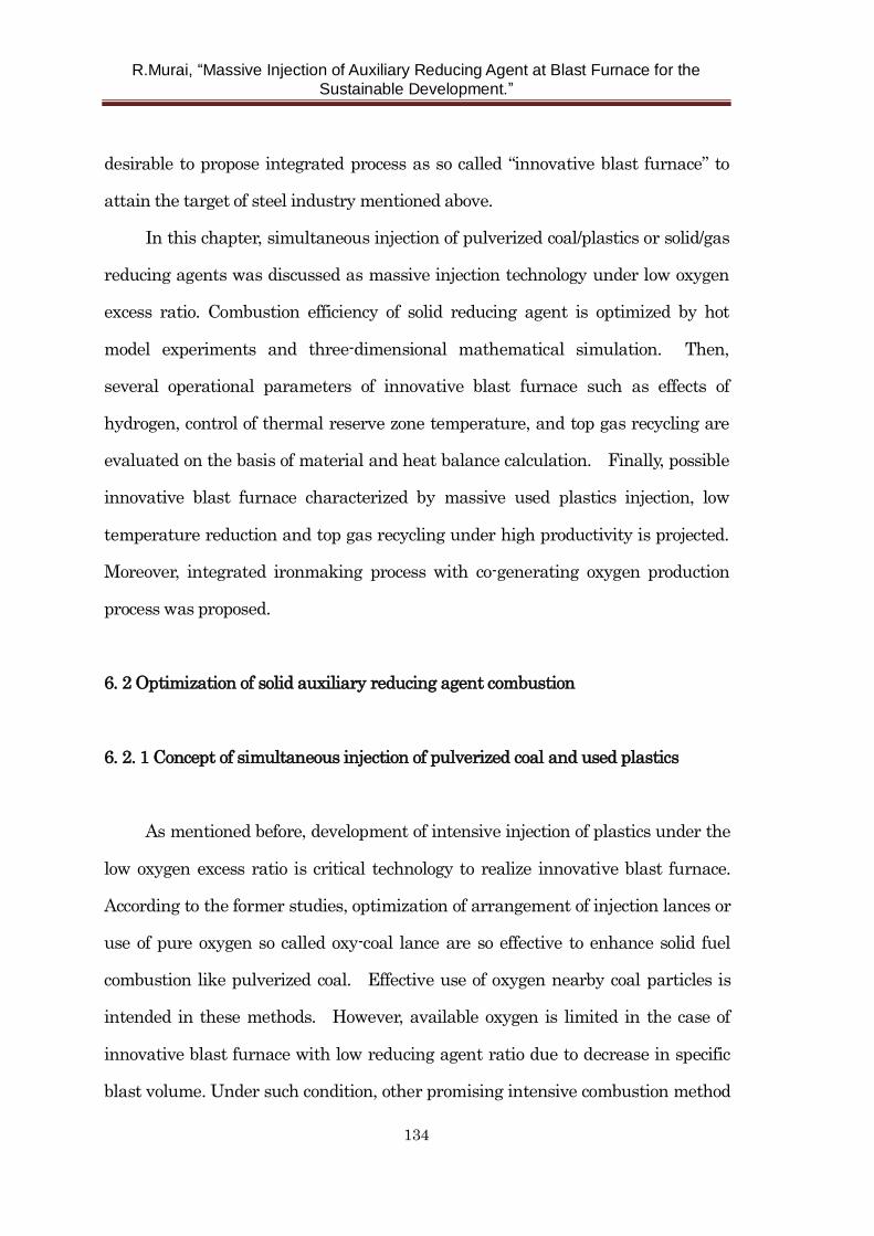
R.Murai, “Massive Injection of Auxiliary Reducing Agent at Blast Furnace for the
Sustainable Development.”
134
desirable to propose integrated process as so called “innovative blast furnace” to
attain the target of steel industry mentioned above.
In this chapter, simultaneous injection of pulverized coal/plastics or solid/gas
reducing agents was discussed as massive injection technology under low oxygen
excess ratio. Combustion efficiency of solid reducing agent is optimized by hot
model experiments and three-dimensional mathematical simulation. Then,
several operational parameters of innovative blast furnace such as effects of
hydrogen, control of thermal reserve zone temperature, and top gas recycling are
evaluated on the basis of material and heat balance calculation. Finally, possible
innovative blast furnace characterized by massive used plastics injection, low
temperature reduction and top gas recycling under high productivity is projected.
Moreover, integrated ironmaking process with co-generating oxygen production
process was proposed.
6. 2 Optimization of solid auxiliary reducing agent combustion
6. 2. 1 Concept of simultaneous injection of pulverized coal and used plastics
As mentioned before, development of intensive injection of plastics under the
low oxygen excess ratio is critical technology to realize innovative blast furnace.
According to the former studies, optimization of arrangement of injection lances or
use of pure oxygen so called oxy-coal lance are so effective to enhance solid fuel
combustion like pulverized coal. Effective use of oxygen nearby coal particles is
intended in these methods. However, available oxygen is limited in the case of
innovative blast furnace with low reducing agent ratio due to decrease in specific
blast volume. Under such condition, other promising intensive combustion method
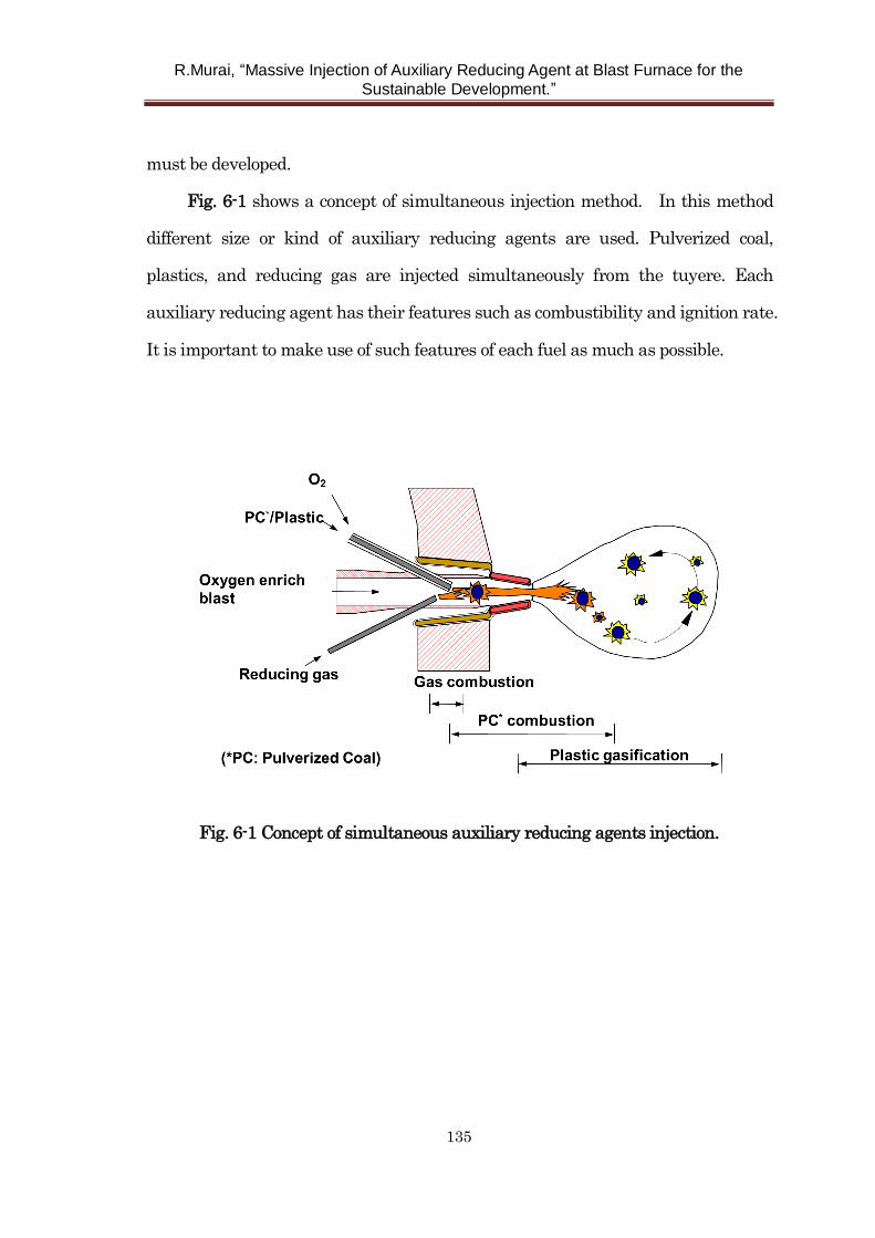
R.Murai, “Massive Injection of Auxiliary Reducing Agent at Blast Furnace for the
Sustainable Development.”
135
must be developed.
Fig. 6-1 shows a concept of simultaneous injection method. In this method
different size or kind of auxiliary reducing agents are used. Pulverized coal,
plastics, and reducing gas are injected simultaneously from the tuyere. Each
auxiliary reducing agent has their features such as combustibility and ignition rate.
It is important to make use of such features of each fuel as much as possible.
Fig. 6-1 Concept of simultaneous auxiliary reducing agents injection.
R.Murai, “Massive Injection of Auxiliary Reducing Agent at Blast Furnace for the
Sustainable Development.”
136
6. 2. 2 Improvement of combustibility by simultaneous injection of pulverized
coal/used plastics
Used plastics are one of the ideal reducing agents replacing coke because it
contains relatively high hydrogen, so carbon emission can be reduced if massive
plastics injection is achieved. Moreover, use of “used” plastics as a reducing agent
in ironmaking process contributes to environmental conservation compared with
use in conventional incineration process.
One of the important subjects in plastics injection is generation of unburnt
char. As mentioned in chapter 3, unburnt char derived from plastics may
accumulate in the lower part of blast furnace. It possibly causes the problem of low
permeability or increase in coke rate. To avoid these situations, used plastics
must be so sufficiently consumed in raceway.
Fig. 6-2 shows an example of an observation result of plastics particle in
the blowpipe of the experimental furnace. Agglomerated plastics of approximately
5mm in diameter are injected into hot blast with temperature of 1473 K in this
case.
R.Murai, “Massive Injection of Auxiliary Reducing Agent at Blast Furnace for the
Sustainable Development.”
137
Fig. 6-2 Observation of combustion behavior of plastic in hot blast.
This photograph was taken through the observation hole located at a position of
300 mm from the injection lance tip in the blowpipe. As shown in this figure, such
coarse plastics particle could not ignite in the blowpipe. Although APR (Advanced
Plastics Recycling method: see chapter 3) was developed recently, the average
diameter of APR is 800 m. That is rather coarse, while the diameter of pulverized
coal is about 50 m, method to improve the reaction of plastic particles in blowpipe
to tuyere region must be developed. Fig. 6-3 shows a calculated temperature of
pulverized coal and plastics particle in blowpipe. Temperature of particle is
calculated considering particle velocity in blowpipe, heat convection through
interface of fluid/solid, and heat conduction inside particle. In the case of plastics,
temperature of particle is rather low due to specific small surface.
Fig. 6-4 shows the change of particle velocity in the blowpipe after injection.
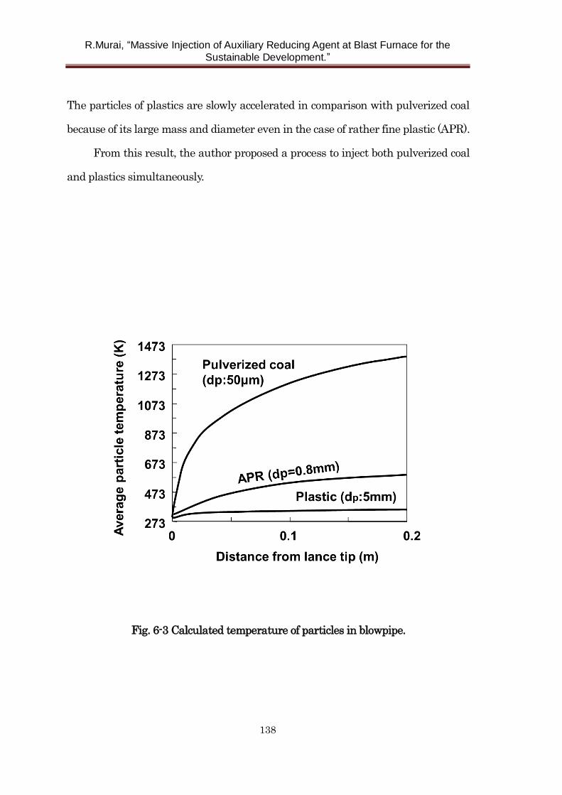
R.Murai, “Massive Injection of Auxiliary Reducing Agent at Blast Furnace for the
Sustainable Development.”
138
The particles of plastics are slowly accelerated in comparison with pulverized coal
because of its large mass and diameter even in the case of rather fine plastic (APR).
From this result, the author proposed a process to inject both pulverized coal
and plastics simultaneously.
Fig. 6-3 Calculated temperature of particles in blowpipe.
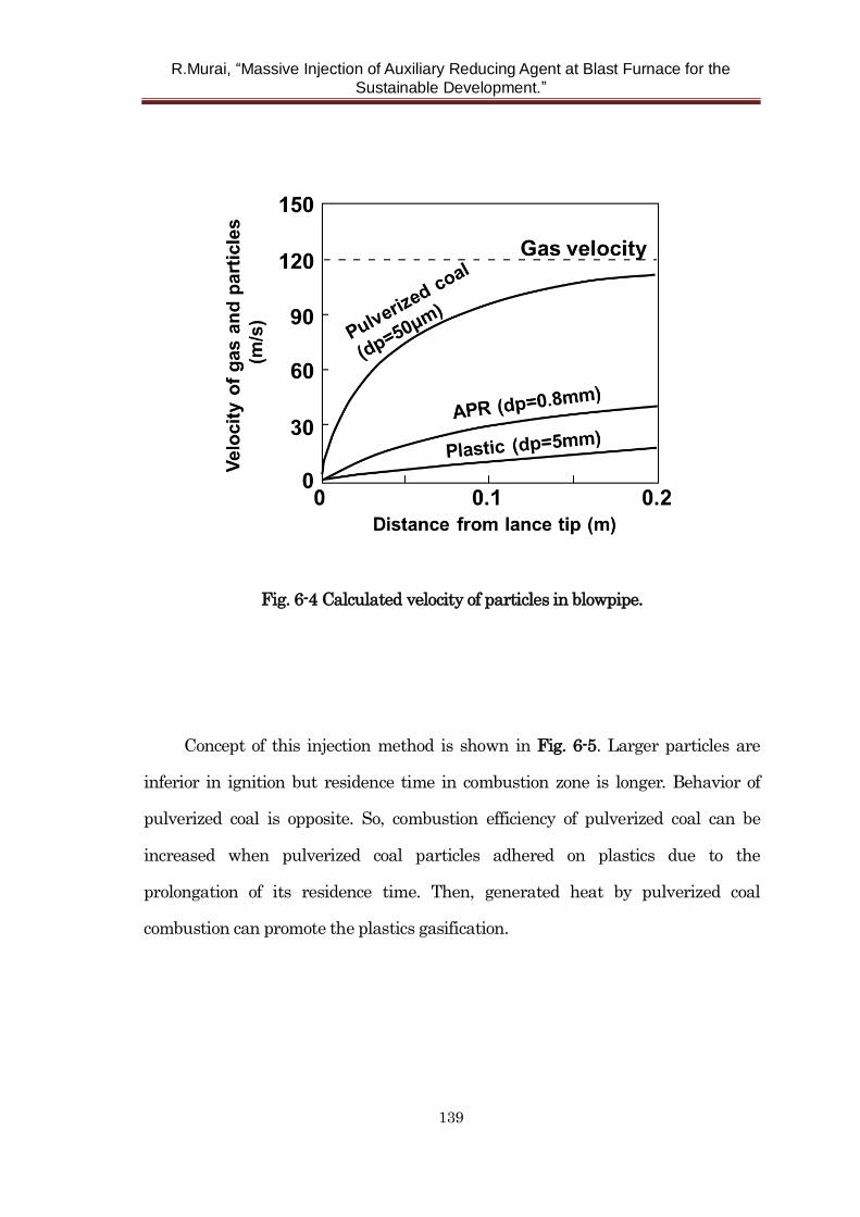
R.Murai, “Massive Injection of Auxiliary Reducing Agent at Blast Furnace for the
Sustainable Development.”
139
Fig. 6-4 Calculated velocity of particles in blowpipe.
Concept of this injection method is shown in Fig. 6-5. Larger particles are
inferior in ignition but residence time in combustion zone is longer. Behavior of
pulverized coal is opposite. So, combustion efficiency of pulverized coal can be
increased when pulverized coal particles adhered on plastics due to the
prolongation of its residence time. Then, generated heat by pulverized coal
combustion can promote the plastics gasification.
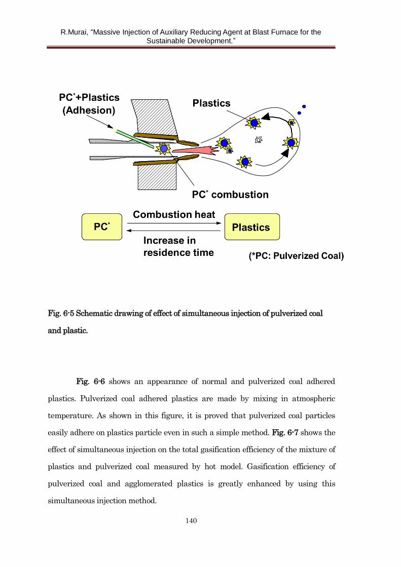
R.Murai, “Massive Injection of Auxiliary Reducing Agent at Blast Furnace for the
Sustainable Development.”
140
Fig. 6-5 Schematic drawing of effect of simultaneous injection of pulverized coal
and plastic.
Fig. 6-6 shows an appearance of normal and pulverized coal adhered
plastics. Pulverized coal adhered plastics are made by mixing in atmospheric
temperature. As shown in this figure, it is proved that pulverized coal particles
easily adhere on plastics particle even in such a simple method. Fig. 6-7 shows the
effect of simultaneous injection on the total gasification efficiency of the mixture of
plastics and pulverized coal measured by hot model. Gasification efficiency of
pulverized coal and agglomerated plastics is greatly enhanced by using this
simultaneous injection method.
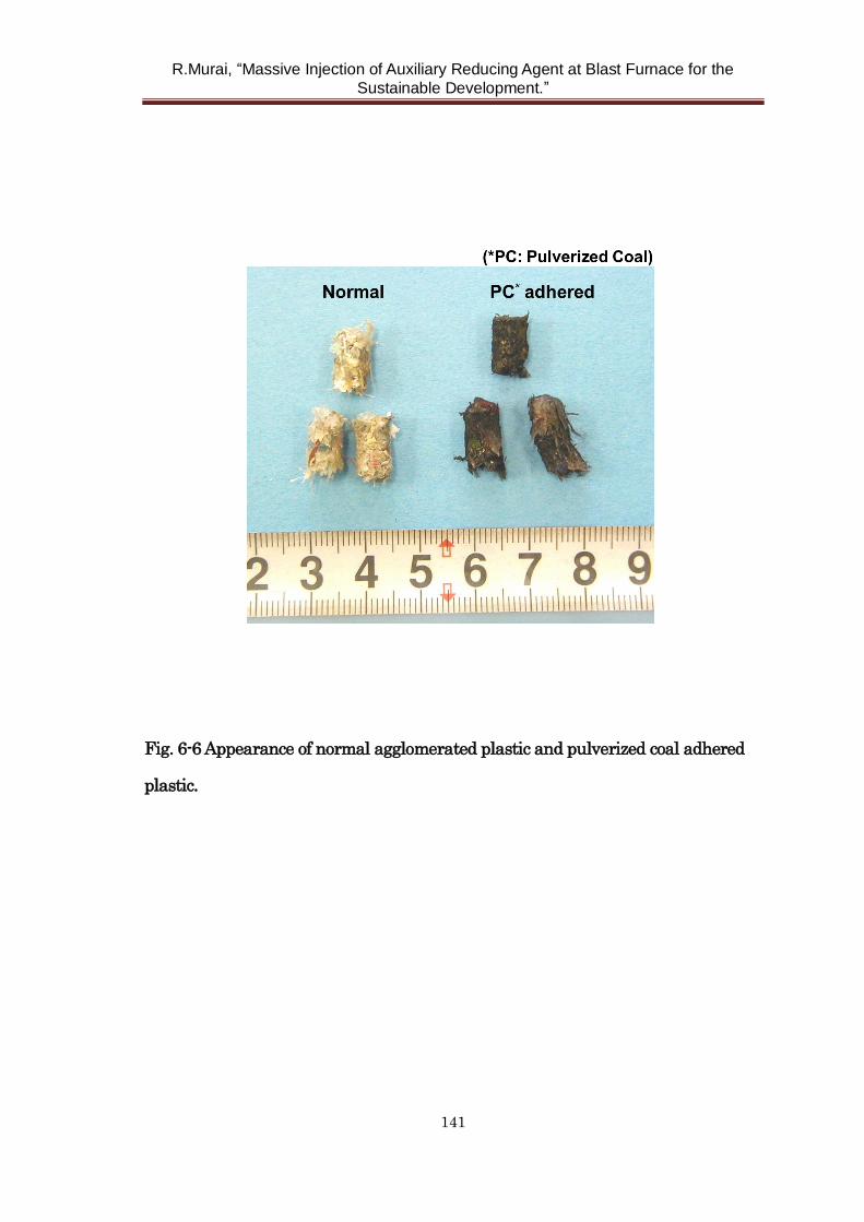
R.Murai, “Massive Injection of Auxiliary Reducing Agent at Blast Furnace for the
Sustainable Development.”
141
Fig. 6-6 Appearance of normal agglomerated plastic and pulverized coal adhered
plastic.
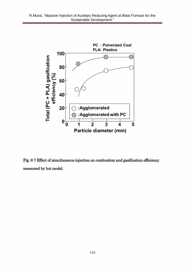
R.Murai, “Massive Injection of Auxiliary Reducing Agent at Blast Furnace for the
Sustainable Development.”
142
Fig. 6-7 Effect of simultaneous injection on combustion and gasification efficiency
measured by hot model.
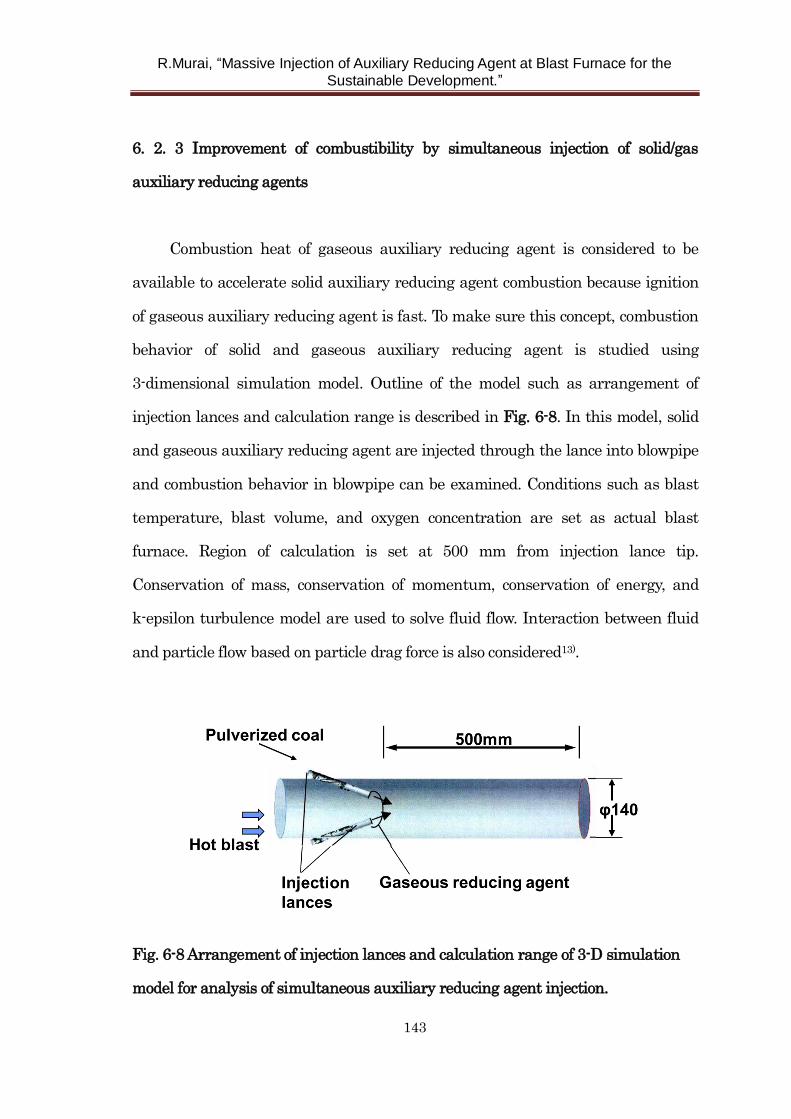
R.Murai, “Massive Injection of Auxiliary Reducing Agent at Blast Furnace for the
Sustainable Development.”
143
6. 2. 3 Improvement of combustibility by simultaneous injection of solid/gas
auxiliary reducing agents
Combustion heat of gaseous auxiliary reducing agent is considered to be
available to accelerate solid auxiliary reducing agent combustion because ignition
of gaseous auxiliary reducing agent is fast. To make sure this concept, combustion
behavior of solid and gaseous auxiliary reducing agent is studied using
3-dimensional simulation model. Outline of the model such as arrangement of
injection lances and calculation range is described in Fig. 6-8. In this model, solid
and gaseous auxiliary reducing agent are injected through the lance into blowpipe
and combustion behavior in blowpipe can be examined. Conditions such as blast
temperature, blast volume, and oxygen concentration are set as actual blast
furnace. Region of calculation is set at 500 mm from injection lance tip.
Conservation of mass, conservation of momentum, conservation of energy, and
k-epsilon turbulence model are used to solve fluid flow. Interaction between fluid
and particle flow based on particle drag force is also considered13).
Fig. 6-8 Arrangement of injection lances and calculation range of 3-D simulation
model for analysis of simultaneous auxiliary reducing agent injection.
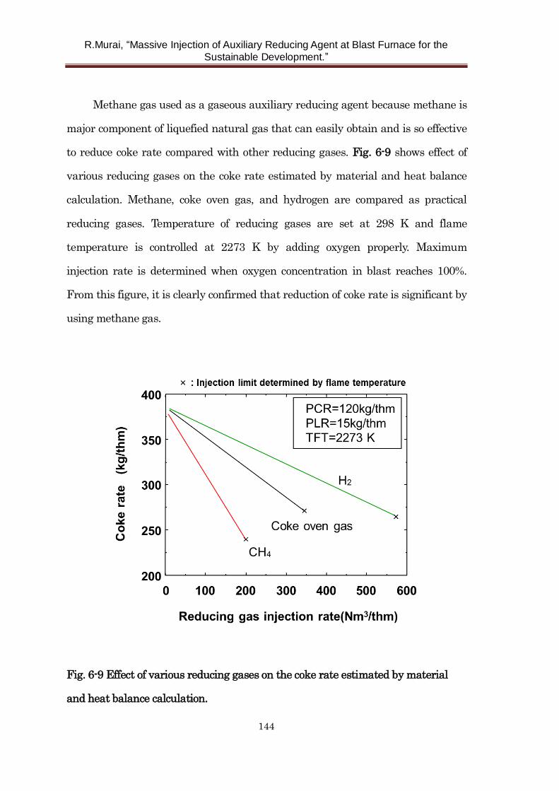
R.Murai, “Massive Injection of Auxiliary Reducing Agent at Blast Furnace for the
Sustainable Development.”
144
Methane gas used as a gaseous auxiliary reducing agent because methane is
major component of liquefied natural gas that can easily obtain and is so effective
to reduce coke rate compared with other reducing gases. Fig. 6-9 shows effect of
various reducing gases on the coke rate estimated by material and heat balance
calculation. Methane, coke oven gas, and hydrogen are compared as practical
reducing gases. Temperature of reducing gases are set at 298 K and flame
temperature is controlled at 2273 K by adding oxygen properly. Maximum
injection rate is determined when oxygen concentration in blast reaches 100%.
From this figure, it is clearly confirmed that reduction of coke rate is significant by
using methane gas.
Fig. 6-9 Effect of various reducing gases on the coke rate estimated by material
and heat balance calculation.
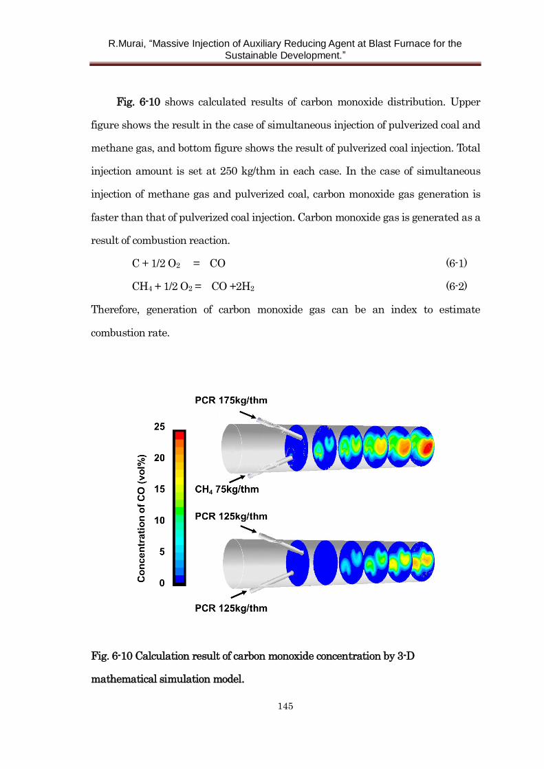
R.Murai, “Massive Injection of Auxiliary Reducing Agent at Blast Furnace for the
Sustainable Development.”
145
Fig. 6-10 shows calculated results of carbon monoxide distribution. Upper
figure shows the result in the case of simultaneous injection of pulverized coal and
methane gas, and bottom figure shows the result of pulverized coal injection. Total
injection amount is set at 250 kg/thm in each case. In the case of simultaneous
injection of methane gas and pulverized coal, carbon monoxide gas generation is
faster than that of pulverized coal injection. Carbon monoxide gas is generated as a
result of combustion reaction.
C + 1/2 O2 = CO (6-1)
CH4 + 1/2 O2 = CO +2H2 (6-2)
Therefore, generation of carbon monoxide gas can be an index to estimate
combustion rate.
Fig. 6-10 Calculation result of carbon monoxide concentration by 3-D
mathematical simulation model.
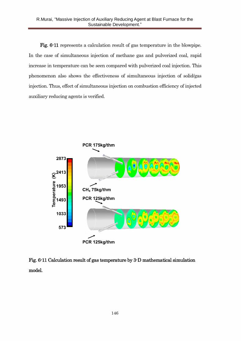
R.Murai, “Massive Injection of Auxiliary Reducing Agent at Blast Furnace for the
Sustainable Development.”
146
Fig. 6-11 represents a calculation result of gas temperature in the blowpipe.
In the case of simultaneous injection of methane gas and pulverized coal, rapid
increase in temperature can be seen compared with pulverized coal injection. This
phenomenon also shows the effectiveness of simultaneous injection of solid/gas
injection. Thus, effect of simultaneous injection on combustion efficiency of injected
auxiliary reducing agents is verified.
Fig. 6-11 Calculation result of gas temperature by 3-D mathematical simulation
model.
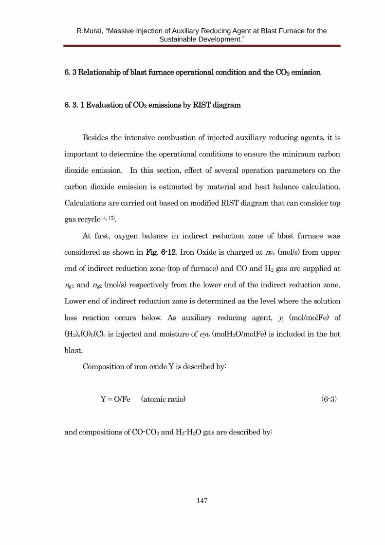
R.Murai, “Massive Injection of Auxiliary Reducing Agent at Blast Furnace for the
Sustainable Development.”
147
6. 3 Relationship of blast furnace operational condition and the CO2 emission
6. 3. 1 Evaluation of CO2 emissions by RIST diagram
Besides the intensive combustion of injected auxiliary reducing agents, it is
important to determine the operational conditions to ensure the minimum carbon
dioxide emission. In this section, effect of several operation parameters on the
carbon dioxide emission is estimated by material and heat balance calculation.
Calculations are carried out based on modified RIST diagram that can consider top
gas recycle14, 15).
At first, oxygen balance in indirect reduction zone of blast furnace was
considered as shown in Fig. 6-12. Iron Oxide is charged at nFe (mol/s) from upper
end of indirect reduction zone (top of furnace) and CO and H2 gas are supplied at
ng1 and ng2 (mol/s) respectively from the lower end of the indirect reduction zone.
Lower end of indirect reduction zone is determined as the level where the solution
loss reaction occurs below. As auxiliary reducing agent, yj (mol/molFe) of
(H2)a(O)b(C)c is injected and moisture of eyb (molH2O/molFe) is included in the hot
blast.
Composition of iron oxide Y is described by:
Y = O/Fe (atomic ratio) (6-3)
and compositions of CO-CO2 and H2-H2O gas are described by:
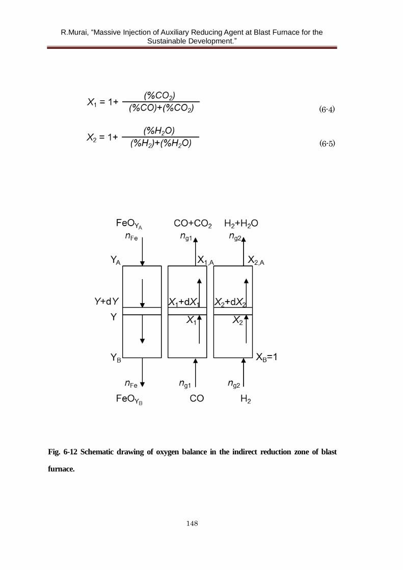
R.Murai, “Massive Injection of Auxiliary Reducing Agent at Blast Furnace for the
Sustainable Development.”
148
(6-4)
(6-5)
Fig. 6-12 Schematic drawing of oxygen balance in the indirect reduction zone of blast
furnace.
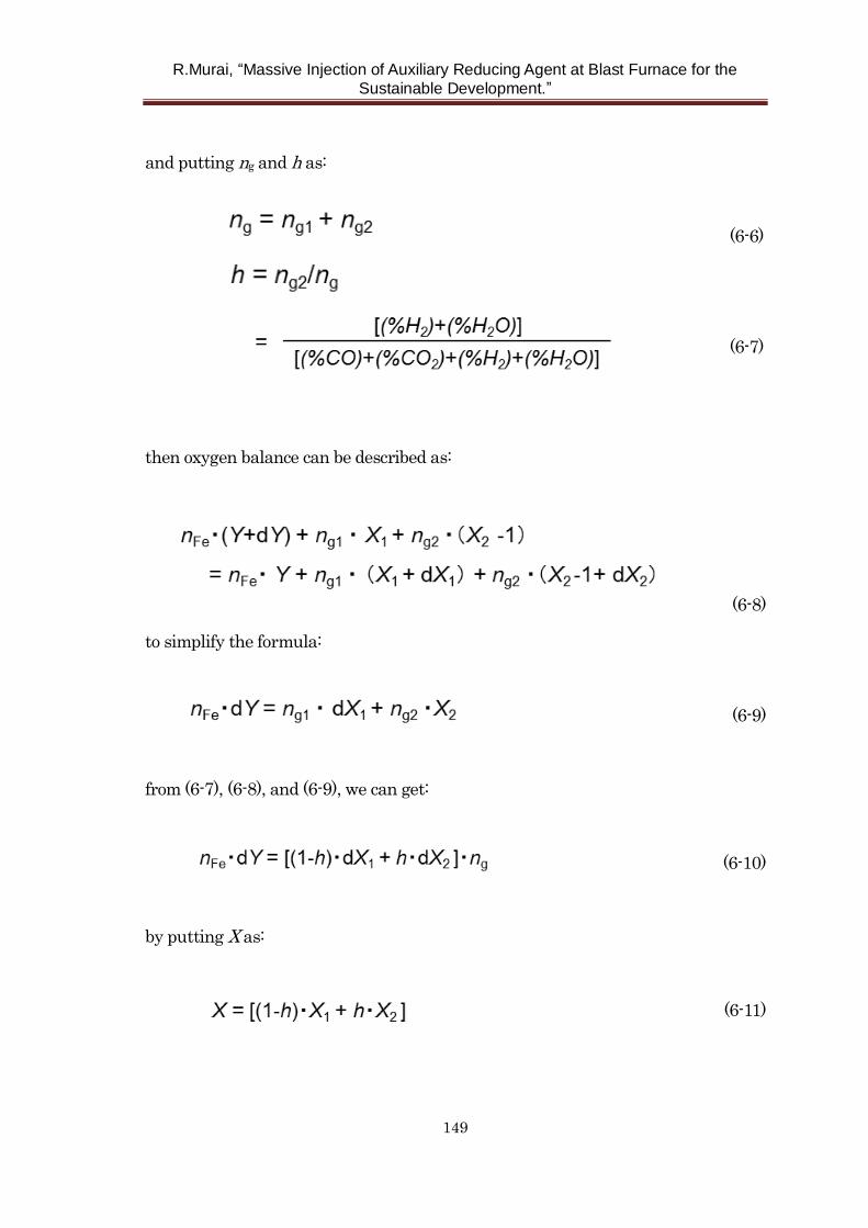
R.Murai, “Massive Injection of Auxiliary Reducing Agent at Blast Furnace for the
Sustainable Development.”
149
and putting ng and h as:
(6-6)
(6-7)
then oxygen balance can be described as:
(6-8)
to simplify the formula:
(6-9)
from (6-7), (6-8), and (6-9), we can get:
(6-10)
by putting X as:
(6-11)
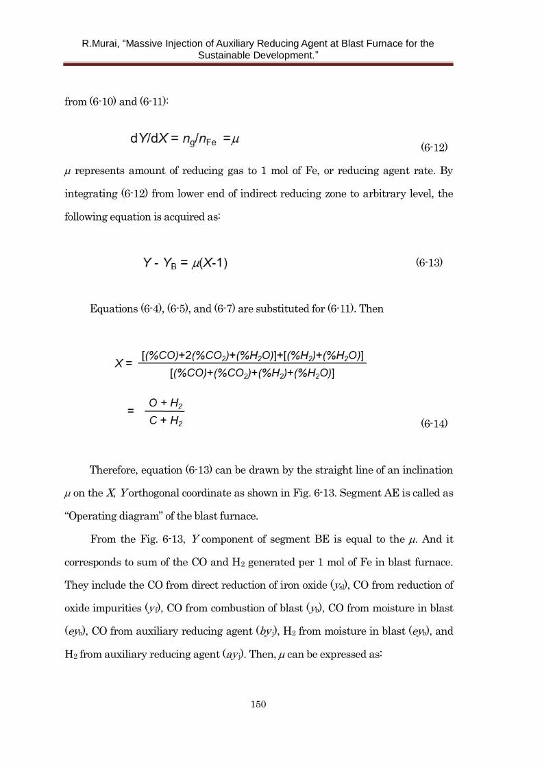
R.Murai, “Massive Injection of Auxiliary Reducing Agent at Blast Furnace for the
Sustainable Development.”
150
from (6-10) and (6-11):
(6-12)
represents amount of reducing gas to 1 mol of Fe, or reducing agent rate. By
integrating (6-12) from lower end of indirect reducing zone to arbitrary level, the
following equation is acquired as:
(6-13)
Equations (6-4), (6-5), and (6-7) are substituted for (6-11). Then
(6-14)
Therefore, equation (6-13) can be drawn by the straight line of an inclination
on the X, Y orthogonal coordinate as shown in Fig. 6-13. Segment AE is called as
“Operating diagram” of the blast furnace.
From the Fig. 6-13, Y component of segment BE is equal to the . And it
corresponds to sum of the CO and H2 generated per 1 mol of Fe in blast furnace.
They include the CO from direct reduction of iron oxide (ysl), CO from reduction of
oxide impurities (y f), CO from combustion of blast (yb), CO from moisture in blast
(eyb), CO from auxiliary reducing agent (by j), H2 from moisture in blast (eyb), and
H2 from auxiliary reducing agent (ay j). Then, can be expressed as:
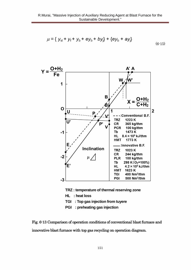
R.Murai, “Massive Injection of Auxiliary Reducing Agent at Blast Furnace for the
Sustainable Development.”
151
(6-15)
Fig. 6-13 Comparison of operation conditions of conventional blast furnace and
innovative blast furnace with top gas recycling on operation diagram.
TRZ : temperature of thermal reserving zone
HL : heat loss
TGI : Top gas injection from tuyere
PGI : preheating gas injection

R.Murai, “Massive Injection of Auxiliary Reducing Agent at Blast Furnace for the
Sustainable Development.”
152
Considering point U on the Fig. 6-13 which satisfies the condition of following
equations:
(6-16)
(6-17)
then the equation (6-13) can be rearranged as:
(6-18)
Equation (6-18) represents oxygen balance in the blast furnace.
Next, heat balance in the blast furnace is considered. From the balance of
heat input and heat output in the processing zone of blast furnace, following
equation can be given as:
(6-19)
Eliminating ysl by (6-18) and (6-19), operating diagram which satisfies both
heat and material (oxygen) balance can be acquired as:
(6-20)
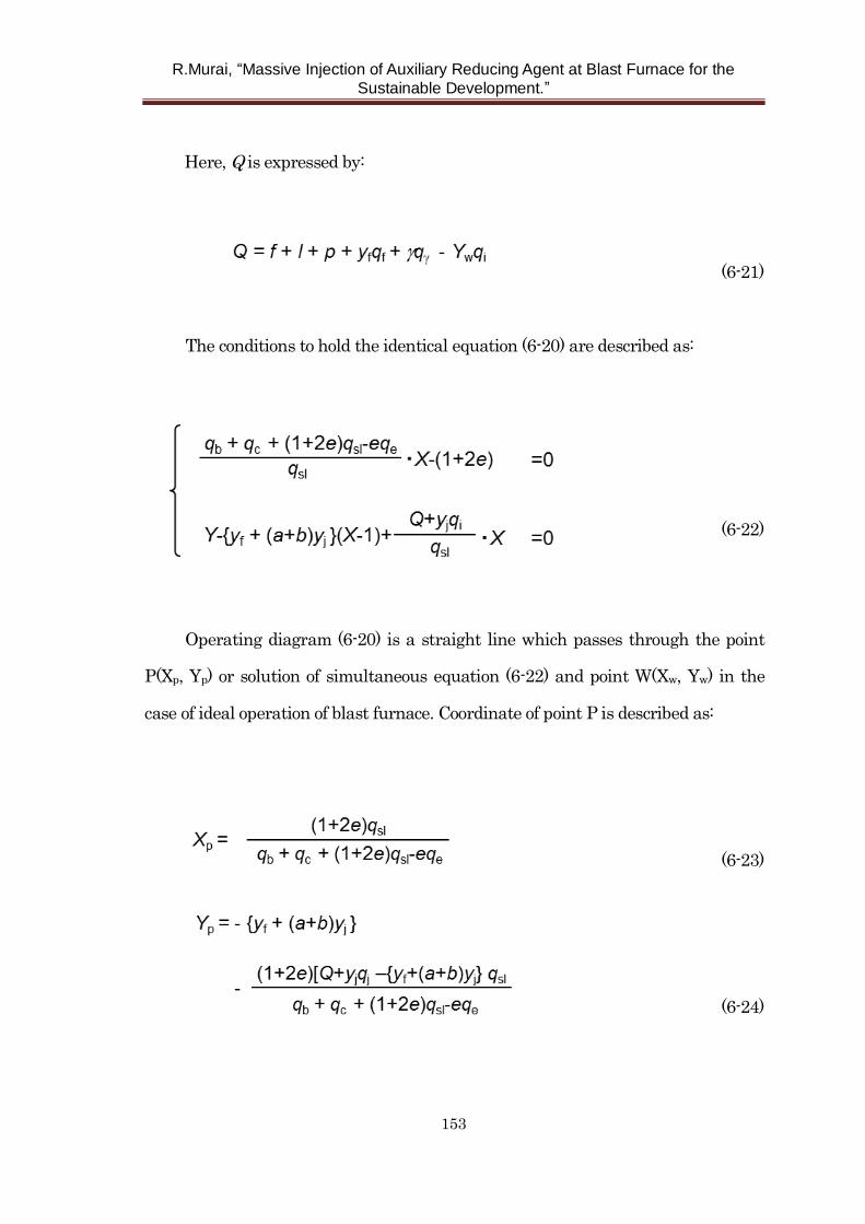
R.Murai, “Massive Injection of Auxiliary Reducing Agent at Blast Furnace for the
Sustainable Development.”
153
Here, Q is expressed by:
(6-21)
The conditions to hold the identical equation (6-20) are described as:
(6-22)
Operating diagram (6-20) is a straight line which passes through the point
P(Xp, Yp) or solution of simultaneous equation (6-22) and point W(Xw, Yw) in the
case of ideal operation of blast furnace. Coordinate of point P is described as:
(6-23)
(6-24)
R.Murai, “Massive Injection of Auxiliary Reducing Agent at Blast Furnace for the
Sustainable Development.”
154
Coordinate of point W that represents equilibrium gas composition of wustite
and metallic Fe depends on the temperature of thermal reserving zone (TRZ).
Lower TRZ temperature leads to larger Xw value. That makes reducing agent rate
() smaller. For example, in the case of TRZ temperature is 1273K under CO-CO2
equilibrium, coordinate of point W is expressed by W(1.295, 1.05).
Then, we can estimate the reducing agent rate () or carbon emission from
blast furnace when auxiliary reducing agent rate (y j), moisture in blast (ey b), and
hot metal temperature (f ) and so on are changed.
Conventional blast furnace and innovative blast furnace with top gas
recycling are compared in Fig. 6-13. Blast furnace is divided into two parts at the
level of upper end of reduction zone and material and heat balance are calculated
in each parts. Reducing gas in top gas is injected to both upper and lower part in
the case of innovative blast furnace. It is assumed here that iron oxide is reduced
till wustite in upper part and further reduction reaction till metallic Fe occurs in
lower part. TRZ temperature is set at 1223 K and 1023 K in conventional blast
furnace and innovative blast furnace respectively. Operation diagrams go through
P or P’ that are called thermal pinch point and W or W’ as mentioned before. Blast
volume is determined by the segment OE or OE’ and flame temperature is
calculated by plastics injection rate, top gas recycling rate and blast condition. In
the case of innovative blast furnace, preheating gas was injected to control heat
flow ratio in upper part. Therefore, gradient from W’ to A’ becomes steeper because
of increase in reducing gas volume. Although apparent reducing agent rate (sum of
coke rate, plastics injection rate and top gas recycling rate) corresponds to gradient
of segment E’W’ is increased, amount of coke and plastics can be reduced
considerably.
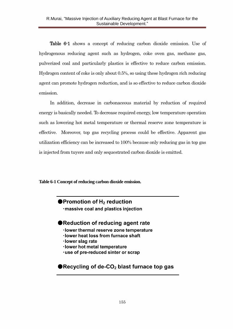
R.Murai, “Massive Injection of Auxiliary Reducing Agent at Blast Furnace for the
Sustainable Development.”
155
Table 6-1 shows a concept of reducing carbon dioxide emission. Use of
hydrogenous reducing agent such as hydrogen, coke oven gas, methane gas,
pulverized coal and particularly plastics is effective to reduce carbon emission.
Hydrogen content of coke is only about 0.5%, so using these hydrogen rich reducing
agent can promote hydrogen reduction, and is so effective to reduce carbon dioxide
emission.
In addition, decrease in carbonaceous material by reduction of required
energy is basically needed. To decrease required energy, low temperature operation
such as lowering hot metal temperature or thermal reserve zone temperature is
effective. Moreover, top gas recycling process could be effective. Apparent gas
utilization efficiency can be increased to 100% because only reducing gas in top gas
is injected from tuyere and only sequestrated carbon dioxide is emitted.
Table 6-1 Concept of reducing carbon dioxide emission.
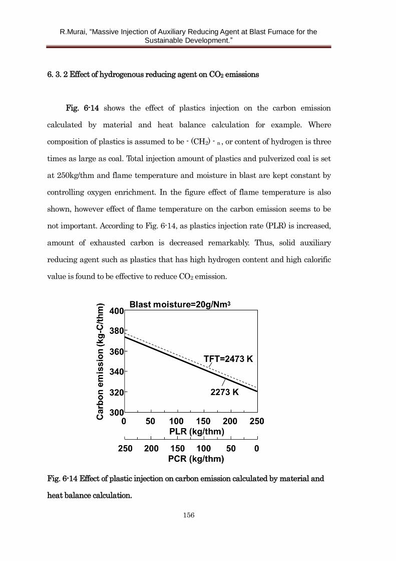
R.Murai, “Massive Injection of Auxiliary Reducing Agent at Blast Furnace for the
Sustainable Development.”
156
6. 3. 2 Effect of hydrogenous reducing agent on CO2 emissions
Fig. 6-14 shows the effect of plastics injection on the carbon emission
calculated by material and heat balance calculation for example. Where
composition of plastics is assumed to be - (CH2) - n , or content of hydrogen is three
times as large as coal. Total injection amount of plastics and pulverized coal is set
at 250kg/thm and flame temperature and moisture in blast are kept constant by
controlling oxygen enrichment. In the figure effect of flame temperature is also
shown, however effect of flame temperature on the carbon emission seems to be
not important. According to Fig. 6-14, as plastics injection rate (PLR) is increased,
amount of exhausted carbon is decreased remarkably. Thus, solid auxiliary
reducing agent such as plastics that has high hydrogen content and high calorific
value is found to be effective to reduce CO2 emission.
Fig. 6-14 Effect of plastic injection on carbon emission calculated by material and
heat balance calculation.
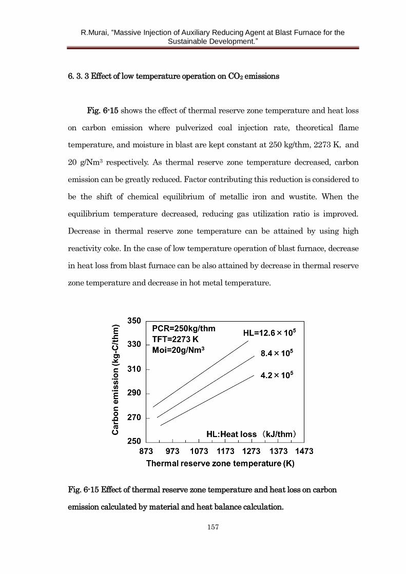
R.Murai, “Massive Injection of Auxiliary Reducing Agent at Blast Furnace for the
Sustainable Development.”
157
6. 3. 3 Effect of low temperature operation on CO2 emissions
Fig. 6-15 shows the effect of thermal reserve zone temperature and heat loss
on carbon emission where pulverized coal injection rate, theoretical flame
temperature, and moisture in blast are kept constant at 250 kg/thm, 2273 K, and
20 g/Nm3 respectively. As thermal reserve zone temperature decreased, carbon
emission can be greatly reduced. Factor contributing this reduction is considered to
be the shift of chemical equilibrium of metallic iron and wustite. When the
equilibrium temperature decreased, reducing gas utilization ratio is improved.
Decrease in thermal reserve zone temperature can be attained by using high
reactivity coke. In the case of low temperature operation of blast furnace, decrease
in heat loss from blast furnace can be also attained by decrease in thermal reserve
zone temperature and decrease in hot metal temperature.
Fig. 6-15 Effect of thermal reserve zone temperature and heat loss on carbon
emission calculated by material and heat balance calculation.
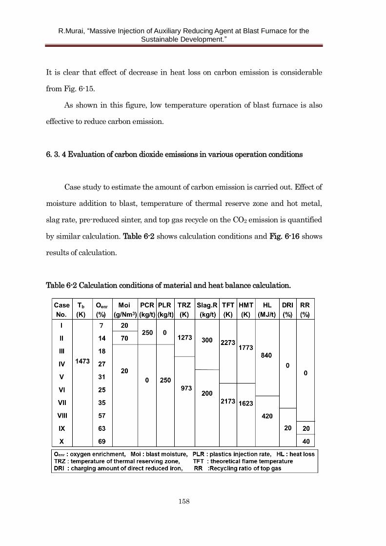
R.Murai, “Massive Injection of Auxiliary Reducing Agent at Blast Furnace for the
Sustainable Development.”
158
It is clear that effect of decrease in heat loss on carbon emission is considerable
from Fig. 6-15.
As shown in this figure, low temperature operation of blast furnace is also
effective to reduce carbon emission.
6. 3. 4 Evaluation of carbon dioxide emissions in various operation conditions
Case study to estimate the amount of carbon emission is carried out. Effect of
moisture addition to blast, temperature of thermal reserve zone and hot metal,
slag rate, pre-reduced sinter, and top gas recycle on the CO2 emission is quantified
by similar calculation. Table 6-2 shows calculation conditions and Fig. 6-16 shows
results of calculation.
Table 6-2 Calculation conditions of material and heat balance calculation.
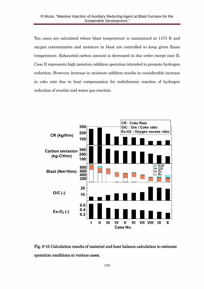
R.Murai, “Massive Injection of Auxiliary Reducing Agent at Blast Furnace for the
Sustainable Development.”
159
Ten cases are calculated where blast temperature is maintained at 1473 K and
oxygen concentration and moisture in blast are controlled to keep given flame
temperature. Exhausted carbon amount is decreased in due order except case II.
Case II represents high moisture addition operation intended to promote hydrogen
reduction. However, increase in moisture addition results in considerable increase
in coke rate due to heat compensation for endothermic reaction of hydrogen
reduction of wustite and water gas reaction.
Fig. 6-16 Calculation results of material and heat balance calculation to estimate
operation conditions at various cases.
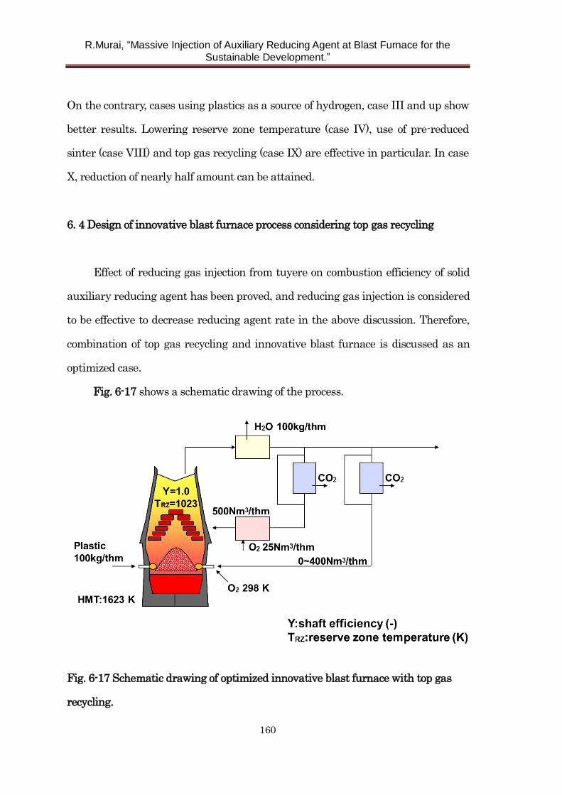
R.Murai, “Massive Injection of Auxiliary Reducing Agent at Blast Furnace for the
Sustainable Development.”
160
On the contrary, cases using plastics as a source of hydrogen, case III and up show
better results. Lowering reserve zone temperature (case IV), use of pre-reduced
sinter (case VIII) and top gas recycling (case IX) are effective in particular. In case
X, reduction of nearly half amount can be attained.
6. 4 Design of innovative blast furnace process considering top gas recycling
Effect of reducing gas injection from tuyere on combustion efficiency of solid
auxiliary reducing agent has been proved, and reducing gas injection is considered
to be effective to decrease reducing agent rate in the above discussion. Therefore,
combination of top gas recycling and innovative blast furnace is discussed as an
optimized case.
Fig. 6-17 shows a schematic drawing of the process.
Fig. 6-17 Schematic drawing of optimized innovative blast furnace with top gas
recycling.
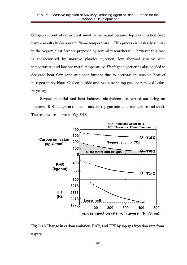
R.Murai, “Massive Injection of Auxiliary Reducing Agent at Blast Furnace for the
Sustainable Development.”
161
Oxygen concentration in blast must be increased because top gas injection from
tuyere results in decrease in flame temperature. This process is basically similar
to the oxygen blast furnace proposed by several researchers8-11), however this case
is characterized by massive plastics injection, low thermal reserve zone
temperature, and low hot metal temperature. Shaft gas injection is also needed to
decrease heat flow ratio at upper furnace due to decrease in sensible heat of
nitrogen in hot blast. Carbon dioxide and moisture in top gas are removed before
recycling.
Several material and heat balance calculations are carried out using an
improved RIST diagram that can consider top gas injection from tuyere and shaft.
The results are shown in Fig. 6-18.
Fig. 6-18 Change in carbon emission, RAR, and TFT by top gas injection rate from
tuyere.
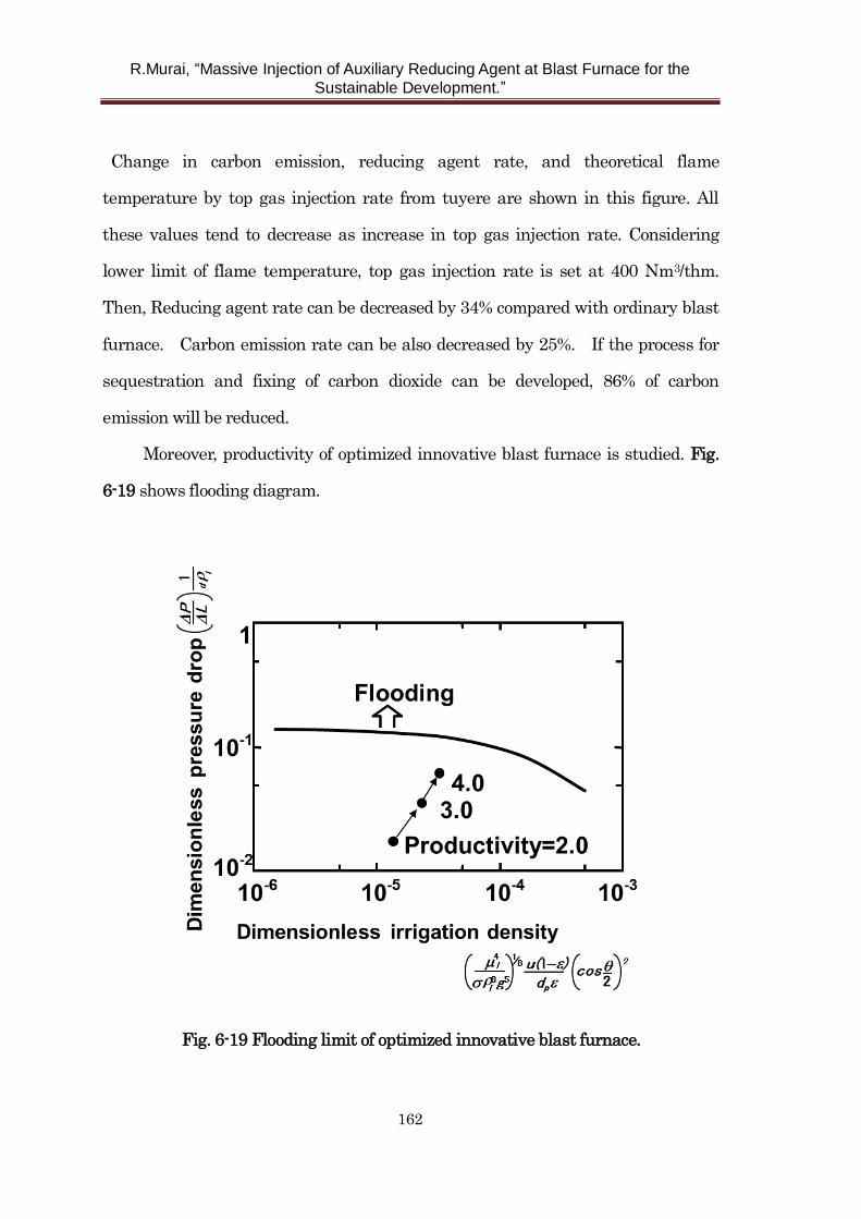
R.Murai, “Massive Injection of Auxiliary Reducing Agent at Blast Furnace for the
Sustainable Development.”
162
Change in carbon emission, reducing agent rate, and theoretical flame
temperature by top gas injection rate from tuyere are shown in this figure. All
these values tend to decrease as increase in top gas injection rate. Considering
lower limit of flame temperature, top gas injection rate is set at 400 Nm3/thm.
Then, Reducing agent rate can be decreased by 34% compared with ordinary blast
furnace. Carbon emission rate can be also decreased by 25%. If the process for
sequestration and fixing of carbon dioxide can be developed, 86% of carbon
emission will be reduced.
Moreover, productivity of optimized innovative blast furnace is studied. Fig.
6-19 shows flooding diagram.
Fig. 6-19 Flooding limit of optimized innovative blast furnace.
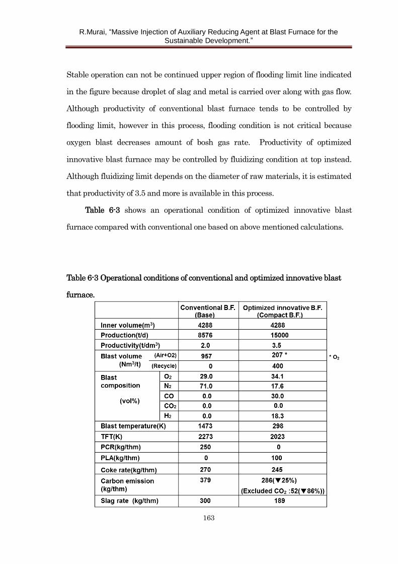
R.Murai, “Massive Injection of Auxiliary Reducing Agent at Blast Furnace for the
Sustainable Development.”
163
Stable operation can not be continued upper region of flooding limit line indicated
in the figure because droplet of slag and metal is carried over along with gas flow.
Although productivity of conventional blast furnace tends to be controlled by
flooding limit, however in this process, flooding condition is not critical because
oxygen blast decreases amount of bosh gas rate. Productivity of optimized
innovative blast furnace may be controlled by fluidizing condition at top instead.
Although fluidizing limit depends on the diameter of raw materials, it is estimated
that productivity of 3.5 and more is available in this process.
Table 6-3 shows an operational condition of optimized innovative blast
furnace compared with conventional one based on above mentioned calculations.
Table 6-3 Operational conditions of conventional and optimized innovative blast
furnace.
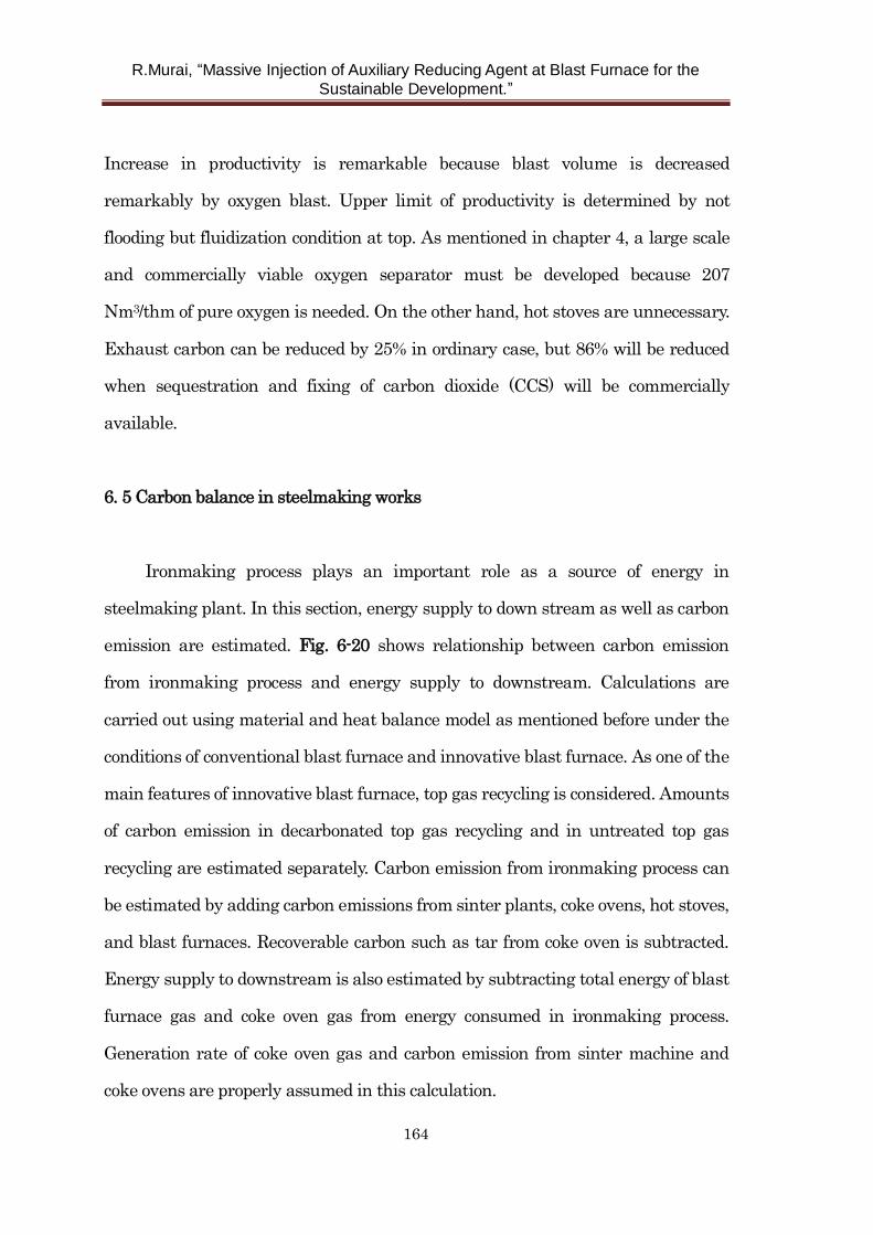
R.Murai, “Massive Injection of Auxiliary Reducing Agent at Blast Furnace for the
Sustainable Development.”
164
Increase in productivity is remarkable because blast volume is decreased
remarkably by oxygen blast. Upper limit of productivity is determined by not
flooding but fluidization condition at top. As mentioned in chapter 4, a large scale
and commercially viable oxygen separator must be developed because 207
Nm3/thm of pure oxygen is needed. On the other hand, hot stoves are unnecessary.
Exhaust carbon can be reduced by 25% in ordinary case, but 86% will be reduced
when sequestration and fixing of carbon dioxide (CCS) will be commercially
available.
6. 5 Carbon balance in steelmaking works
Ironmaking process plays an important role as a source of energy in
steelmaking plant. In this section, energy supply to down stream as well as carbon
emission are estimated. Fig. 6-20 shows relationship between carbon emission
from ironmaking process and energy supply to downstream. Calculations are
carried out using material and heat balance model as mentioned before under the
conditions of conventional blast furnace and innovative blast furnace. As one of the
main features of innovative blast furnace, top gas recycling is considered. Amounts
of carbon emission in decarbonated top gas recycling and in untreated top gas
recycling are estimated separately. Carbon emission from ironmaking process can
be estimated by adding carbon emissions from sinter plants, coke ovens, hot stoves,
and blast furnaces. Recoverable carbon such as tar from coke oven is subtracted.
Energy supply to downstream is also estimated by subtracting total energy of blast
furnace gas and coke oven gas from energy consumed in ironmaking process.
Generation rate of coke oven gas and carbon emission from sinter machine and
coke ovens are properly assumed in this calculation.
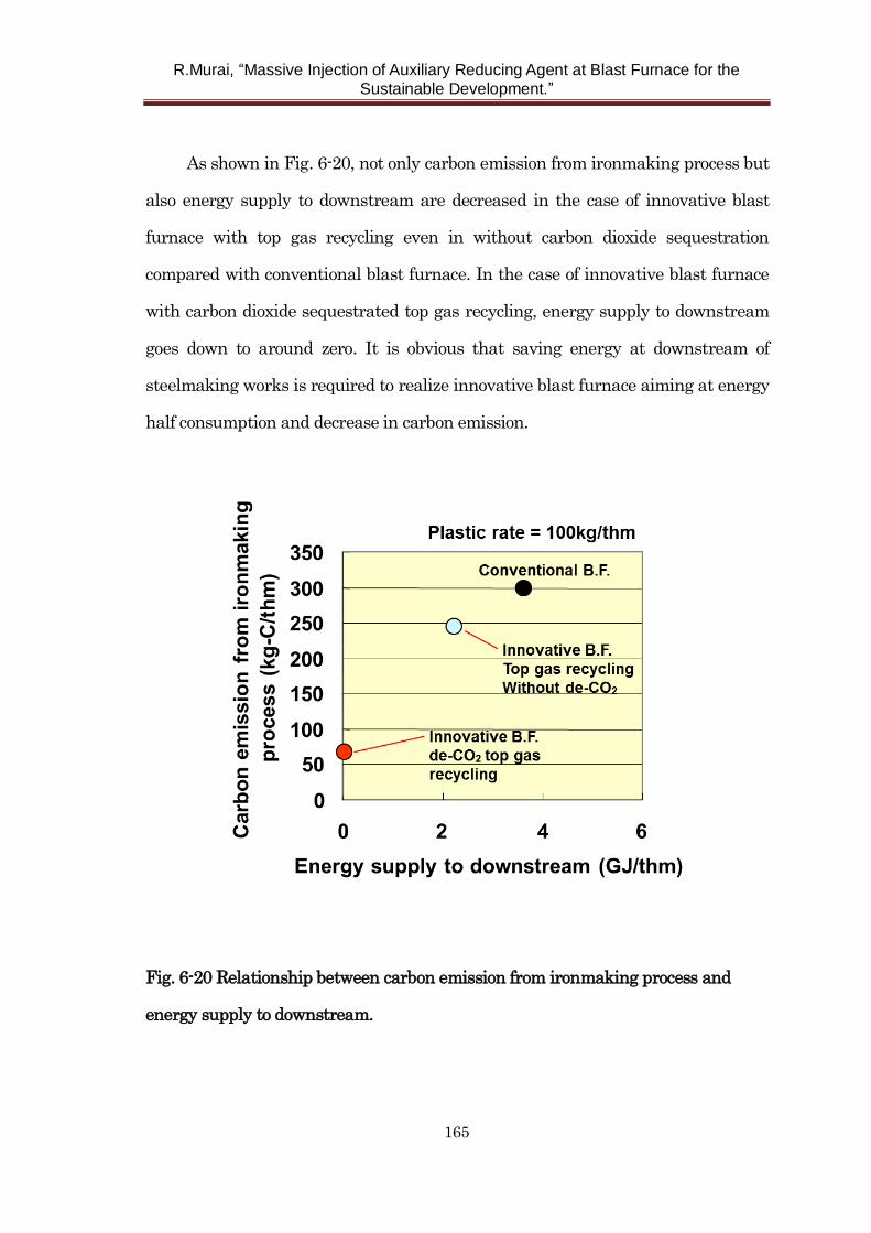
R.Murai, “Massive Injection of Auxiliary Reducing Agent at Blast Furnace for the
Sustainable Development.”
165
As shown in Fig. 6-20, not only carbon emission from ironmaking process but
also energy supply to downstream are decreased in the case of innovative blast
furnace with top gas recycling even in without carbon dioxide sequestration
compared with conventional blast furnace. In the case of innovative blast furnace
with carbon dioxide sequestrated top gas recycling, energy supply to downstream
goes down to around zero. It is obvious that saving energy at downstream of
steelmaking works is required to realize innovative blast furnace aiming at energy
half consumption and decrease in carbon emission.
Fig. 6-20 Relationship between carbon emission from ironmaking process and
energy supply to downstream.
R.Murai, “Massive Injection of Auxiliary Reducing Agent at Blast Furnace for the
Sustainable Development.”
166
6. 6 Concept of innovative blast furnace integrated with co-generating oxygen
production system
Low temperature operation, massive injection of plastics under low oxygen
excess ratio condition, and top gas recycling are the key technologies for the
innovative blast furnace. Apart from these, development of commercially viable
process for oxygen production and sequestration of carbon dioxide is necessary.
Cryogenic distillation is the most spread air separation method. However, to
liquefy the air, a large amount of energy is required. Therefore, the author focused
on the oxygen storage material used in PSA or TSA process in chapter 4. In
addition to this, oxygen separation by membrane filter is under development16,17).
This method can separate oxygen through inorganic membrane. These methods
may be able to produce pure oxygen inexpensively compared with cryogenic
distillation. Concept of integration of innovative blast furnace and oxygen
production system is described in Fig. 6-21. In PSA/TSA air separation process,
high temperature of 800-1000K is needed, and in membrane air separation process,
oxygen transfer can be enhanced under conditions of high temperature of about
1173 K and high oxygen partial pressure. Therefore, a part of top gas is used in
partial combustion chamber to heat up air. Top gas pressure is recovered by
turbine to generate power and power is used to compress the air or at other plant
such as carbon dioxide sequestration. Oxygen separated in this process can be used
at innovative blast furnace. This process can be efficient ironmaking system
characterized by integrated blast furnace process with co-generating oxygen
production.
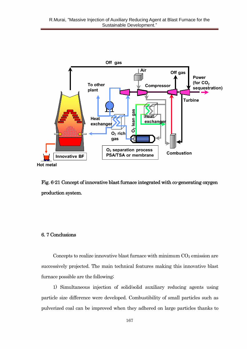
R.Murai, “Massive Injection of Auxiliary Reducing Agent at Blast Furnace for the
Sustainable Development.”
167
Fig. 6-21 Concept of innovative blast furnace integrated with co-generating oxygen
production system.
6. 7 Conclusions
Concepts to realize innovative blast furnace with minimum CO2 emission are
successively projected. The main technical features making this innovative blast
furnace possible are the following;
1) Simultaneous injection of solid/solid auxiliary reducing agents using
particle size difference were developed. Combustibility of small particles such as
pulverized coal can be improved when they adhered on large particles thanks to
R.Murai, “Massive Injection of Auxiliary Reducing Agent at Blast Furnace for the
Sustainable Development.”
168
prolongation of their residence time. Then, generated heat by combustion of
small particle can promote the gasification and combustion of large particles.
2) Simultaneous injection of solid/gas fuel was developed. Combustion heat of
gaseous auxiliary reducing agent was considered to be available to accelerate solid
auxiliary reducing agent combustion because ignition of gaseous auxiliary
reducing agent is rapid.
3) Use of hydrogen rich reducing agent such as hydrogen, coke oven gas,
methane gas, pulverized coal, and particularly plastics and promoting hydrogen
reduction is so useful to reduce carbon dioxide emission.
4) Low temperature operation of blast furnace is also favorable to reduce
carbon emission for example decrease in thermal reserve zone temperature and
heat loss from the blast furnace.
5) Top gas recycling process could be effective. Apparent gas utilization
efficiency can be increased to 100% if only reducing gas in top gas is injected from
tuyere and only sequestrated carbon dioxide is emitted.
6) To combine with efficient oxygen production process, integration of
innovative blast furnace and co-generating oxygen production system was newly
proposed.
As a whole, it is expected that 86% of exhaust carbon can be reduced in
optimized innovative blast furnace with top gas recycling and sequestration and
fixing of carbon dioxide. Productivity can be also enhanced due to relaxation of
flooding condition in this process. Productivity of 3.5 and more can be attained in
this innovative ironmaking process. This innovative blast furnace enables to solve
global warming problem in future.
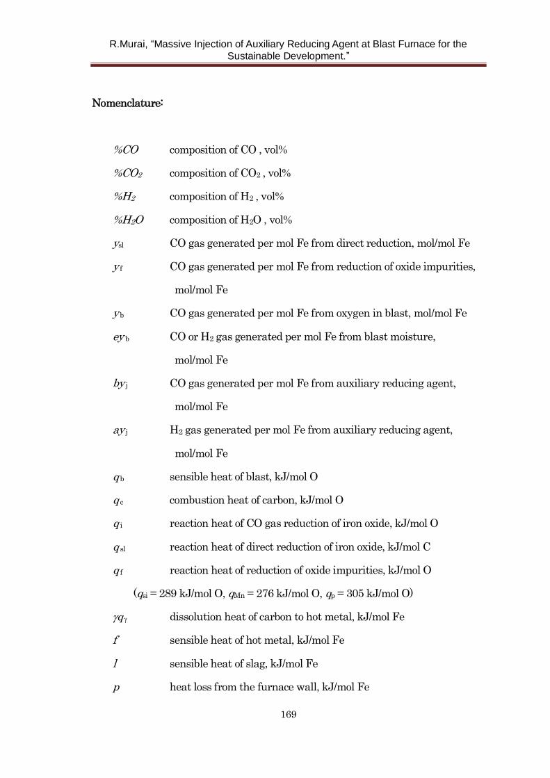
R.Murai, “Massive Injection of Auxiliary Reducing Agent at Blast Furnace for the
Sustainable Development.”
169
Nomenclature:
%CO composition of CO , vol%
%CO2 composition of CO2 , vol%
%H2 composition of H2 , vol%
%H2O composition of H2O , vol%
ysl CO gas generated per mol Fe from direct reduction, mol/mol Fe
y f CO gas generated per mol Fe from reduction of oxide impurities,
mol/mol Fe
y b CO gas generated per mol Fe from oxygen in blast, mol/mol Fe
ey b CO or H2 gas generated per mol Fe from blast moisture,
mol/mol Fe
by j CO gas generated per mol Fe from auxiliary reducing agent,
mol/mol Fe
ay j H2 gas generated per mol Fe from auxiliary reducing agent,
mol/mol Fe
q b sensible heat of blast, kJ/mol O
q c combustion heat of carbon, kJ/mol O
q i reaction heat of CO gas reduction of iron oxide, kJ/mol O
q sl reaction heat of direct reduction of iron oxide, kJ/mol C
q f reaction heat of reduction of oxide impurities, kJ/mol O
(qsi = 289 kJ/mol O, qMn = 276 kJ/mol O, qp = 305 kJ/mol O)
q dissolution heat of carbon to hot metal, kJ/mol Fe
f sensible heat of hot metal, kJ/mol Fe
l sensible heat of slag, kJ/mol Fe
p heat loss from the furnace wall, kJ/mol Fe

R.Murai, “Massive Injection of Auxiliary Reducing Agent at Blast Furnace for the
Sustainable Development.”
170
q e reaction heat of moisture in blast, kJ/mol Fe
q j reaction heat of auxiliary reducing agent, kJ/mol Fe
R.Murai, “Massive Injection of Auxiliary Reducing Agent at Blast Furnace for the
Sustainable Development.”
171
References
1) The Japan Iron and Steel Federation: Report of Commitment to a Low Carbon
Society in January 2015.
2) M. Naito and S. Matsuzaki: CAMP-ISIJ, 17(2004),2.
3) G. Tashiro, O. Anzai, G. Kousaka and A. Matsui: CAMP-ISIJ, 15(2002),866.
4) M. Asanuma, T. Ariyama, M. Sato, R. Murai and T. Sumigama: Tetsu-to-Hagane,
83(1997)13.
5) M. Asanuma, T. Ariyama, M. Sato, R. Murai, T. Nonaka, I. Okochi, H. Tsukiji
and K. Nemoto: ISIJ Int., 40(2000),244.
6) T. Ariyama: CAMP-ISIJ, 14(2001),200.
7) R. Suzuki, Y. Kashiwaya and K. Ishii: CAMP-ISIJ, 16(2003),928.
8) K. Ohno, T. Nagasaka and M. Hino: Steel Research, 74(2003),5
9) Y. Ohno, M. Matsuura, H. Mitsufuji and T. Furukawa : ISIJ Int., 32(1992),838.
10) W-K. Lu and R. V. Kumar : ISS Trans., 5(1984),25.
11) Q. Minsheng and Y. Naifu : Scan. J. Met., 15(1986),138.
12) F. Fink : Proc. European Ironmaking Cong., VDEh, Dusseldorf, (1986), PV-3.
13) B. E. Launder and D. B. Spalding : Mathematical Models of Turbulence,
Academic Press, New York (1972).
14) A. Rist and N. Meysson : J. Metals, (1967), p.50
15) Y. Ono: Tetsu-to-Hagane, 79(1993), N618.
16) Y. Teraoka, H. Zhang, S. Furukawa and N. Yamazoe: Chem. Lett.,(1985),1743
17) J. Ishii, T. Anyashiki, M. Asanuma, K. Yabuta, T. Ariyama, C. Fisher, Y.
Iwamoto and Y. Ikuhara: CAMP-ISIJ, 17(2004),92.
R.Murai, “Massive Injection of Auxiliary Reducing Agent at Blast Furnace for the
Sustainable Development.”
172
Chapter 7 General conclusions
Auxiliary reducing agents used in blast furnace such as pulverized coal, used
plastics, and natural gas contain a lot of hydrogen compared with coke. It is
thought that massive auxiliary reducing agent injection at blast furnace could
contribute to mitigation of carbon dioxide emissions. To cope with global warming
problem, further research and development of this field will be required. Moreover,
construction of a circulation type society by effective use of used plastics is so
significant as Japan has to depend on import for most of resources.
Technical problems to increase the injection rate of auxiliary reducing agents
and to mitigate carbon dioxide emissions are
1) Enhancement of combustion efficiency of pulverized coal.
2) Clarification of the plastic particle behavior in the blast furnace and
optimizing the injection condition of plastics.
3) Development of a novel, economically viable oxygen production process.
4) Development of new cooling system with a high cooling capability for
coping with increase in heat load to furnace wall.
5) Integration of various elemental technologies.
Therefore, the purpose of this thesis is to solve the above-mentioned problems for
massive injection of auxiliary reducing agent at blast furnace. This chapter
summarizes this thesis.
In chapter 1, a general introduction was provided. First, current status of
global warming and the role to be performed by steel making industries was
R.Murai, “Massive Injection of Auxiliary Reducing Agent at Blast Furnace for the
Sustainable Development.”
173
introduced; second, resent technologies of liquid, solid, and gas phase auxiliary
reducing agent injection were reviewed; third, conventional oxygen production
methods were explained; fourth, needs of furnace wall protection under massive
injection of auxiliary reducing agent were described and conventional cooling
system was reviewed; and finally, the purpose and contents of this thesis were
described.
In chapter 2, new injection lance with convergent – divergent nozzle for
pulverized coal injection was developed.
First; as the results of the experimental results performed by offline
apparatus, optimum angles of divergence and convergence turned out to be 7 and 5
degrees respectively. Optimum divergence angle could be explained by the theory
of flow separation. On the other hand, it is suggested that segregation of particle to
relatively peripheral region at the throat part in the lance may be occurred due to
the inertia of coal particles in the convergence part. It was thought that this
segregation phenomenon played significant role to the good dispersibility of the
lance.
Second; after the lance was tested at hot model experimental furnace,
convergent-divergent injection lance was installed in the actual blast furnace. As a
result, superior characteristics of the lance including higher particle dispersibility,
higher combustibility, and higher coke replacement ratio compared with normal
straight injection lance proved.
In chapter 3, flow and gasification behavior of injected plastic particle in the
blast furnace was clarified.
First; gasification mechanism was estimated by the observation results of
R.Murai, “Massive Injection of Auxiliary Reducing Agent at Blast Furnace for the
Sustainable Development.”
174
heated plastics with a similar conditions of actual blast furnace. It was presumed
that volatile matter of plastics was evolved at the surface of the particle. Then,
gasification rates of the char were analyzed by thermogravimetric analysis. It was
found that gasification rate of unburnt char depended on the heating rate.
Gasification rate in the case of rapid heating condition tends to increase.
Second; Trajectories of plastic particles injected into blast furnace were
calculated by mathematical model considering decrease in particle size by
gasification. As a result, it is suggested that fine plastics (for example APR)
injection is desirable for the stable operation of blast furnace.
In chapter 4, the high capacity oxygen storage material, Ca2AlMnO5, which
has applications in air-separation technology, was synthesized by
glycine-nitrate-based solution combustion synthesis (SCS).
First; it was found that maximum reversible oxygen uptake and release
amounts of single phase Ca2AlMnO5 was about 3.0 wt%. Ca2AlMnO5 was
successfully synthesized with various glycine contents.
Second; Condition to synthesize single phase Ca2AlMnO5 was determined.
That is SCS and just one minute of heat treatment at 1250 ˚C. Longer periods of
heat-treatment leads to greater crystallinity and larger reversible oxygen storage
capacities.
In chapter 5, cooling staves (CS) made by cast copper have been newly
developed to cope with increase in heat load to the furnace wall in the case of
massive auxiliary reducing agent injection.
First; according to simulations by finite element method, maximum
temperature and maximum thermal stress of cast copper CS was one third and
R.Murai, “Massive Injection of Auxiliary Reducing Agent at Blast Furnace for the
Sustainable Development.”
175
one sixth level compared with conventional cast iron CS respectively.
Second; heat removal amount of cast copper CS was estimated as same level
as that of conventional cast iron CS at actual blast furnace. One of the reasons of
that slag accretion layer may be formed on the surface of cast copper CS by
estimating the measurement results of CS body temperature.
Third; in comparison, thermal conductivity of cast copper CS is slightly
inferior to that of rolled copper CS. However, cooling capabilities of both CS were
approximately same. Cast copper may be superior to rolled copper as a raw
material of CS in terms of the flexibility and processability.
Thus, cast copper CS is so effective to maintain stable operation and prolong
blast furnace campaign life at high rate injection of auxiliary reducing agent
operation.
In chapter 6; by integrating several elemental technologies, concepts to
realize innovative blast furnace with minimum carbon dioxide emission
characterized by massive auxiliary reducing agent injection was projected.
First; to enhance gasification or combustion efficiency, simultaneous injection
of solid/ solid or solid/ gas was developed. In the case of solid/ solid injection, point
is the velocity gaps that is caused by difference of size. Combustibility of small
particles such as pulverized coal can be improved when they adhered on large
particles by the prolongation effect of their residence time. Then, generated heat
by combustion of small particle can promote the gasification of large particles. As a
result, reaction both small and large particles may be promoted.
Second; hydrogen, coke oven gas, methane gas (natural gas), pulverized coal,
and particularly plastics are confirmed to be so useful to reduce carbon dioxide
emission because hydrogen reduction is promoted. Top gas recycling and low

R.Murai, “Massive Injection of Auxiliary Reducing Agent at Blast Furnace for the
Sustainable Development.”
176
temperature operation for example decrease in thermal reserve zone temperature
is also desirable to reduce carbon emissions.
Third; combining efficient oxygen production process as mentioned in chapter
4 and innovative blast furnace is promising process to reduce carbon emissions. It
is expected that 86% of exhaust carbon can be reduced in optimized innovative
blast furnace with top gas recycling and CCS (carbon capture and storage).
R.Murai, “Massive Injection of Auxiliary Reducing Agent at Blast Furnace for the
Sustainable Development.”
177
List of Publications related to the dissertation
Ryota Murai, Yusuke Kashihara, Akinori Murao, Michitaka Sato,
"Convergent-Divergent Injection Lance for the Enhancement of Combustion
Efficiency of Pulverized Coal at Blast Furnace" ISIJ International, Vol.56, No.5,
pp.770-776(2016)
Ryota Murai, Minoru Asanuma, Michitaka Sato, Takanori Inoguchi, Kaneo Terada,
"Flow Behavior of Plastic Particles in the Lower Part of Blast Furnace" ISIJ
International, Vol.55, No.3, pp.528-535(2015)
Takahiro Nomura, Chunyu Zhu, Nan Sheng, Ryota Murai, Tomohiro Akiyama,
"Solution combustion synthesis of Brownmillerite-type Ca2AlMnO5 as an oxygen
storage material" J. of Alloys and Compounds, Vol.646, pp.900-905(2015)
Ryota Murai, Tatsuro Ariyama, Koichi Kimura, Makoto Gocho, Atsushi Sakai,
Masaaki Sakurai, Masahiro Matsuura, Akira Maki, “Development of cast copper
cooling staves and its application to commercial blast furnace” Tetsu-to Hagane,
Vol.88,No.9,pp.487-492(2002)
Ryota Murai, Michitaka Sato, Tatsuro Ariyama, "Design of Innovative Blast
Furnace for Minimizing CO2 Emission Based on Optimization of Solid Fuel
Injection and Top Gas Recycling" ISIJ International, Vol.44, No.12,
pp.2168-2177(2004)
R.Murai, “Massive Injection of Auxiliary Reducing Agent at Blast Furnace for the
Sustainable Development.”
178
Acknowledgement
First of all, I would like to express my deep and sincere gratitude to my
supervisor Prof. Tomohiro Akiyama, Ph. D., professor of the Center for Advanced
Research of Energy and Materials, Hokkaido University. His considerable
encouragement, and detailed advice has been of great help for me.
I also would like to thank to the members of examining committee: Prof.
Ryosuke Suzuki, Prof. Naoyuki Hashimoto, Associate Prof. Naoto Tsubouchi and
Takahiro Nomura whose constructive comments were invaluable contribution.
I wish to express my thanks to all the members in the Akiyama Laboratory,
especially Dr. Chunyu Zhu and Dr. Nan Sheng for kind help and encouragement.
I would like to express my gratitude to the professor emeritus Kuniyoshi Ishii
(Hokkaido Univ.) and professor emeritus Tatsuro Ariyama (Tohoku Univ.) who
gave me some pertinent advice and a lot of encouragement.
This study has been conducted in Steel Research Laboratory, JFE Steel
Corporation. I would like to express my thanks for Dr. Yasuhiro Sodani, Dr. Saiji
Matsuoka and Dr. Ikuhiro Sumi for giving me opportunity of this study.
I would like to express my thanks for Dr. Akio Fujibayashi, Dr. Michitaka
Sato and Dr. Hidetoshi Matsuno for their useful and practical advice.
I would like to express my thanks for co-researcher for their kindly help and
encouragement. Especially, Mr. Akira Maki, Mr. Koichi Kimura, Mr. Atsushi Sakai,
Mr. Masaaki Sakurai, Mr. Makoto Gocho, Mr. Masahiro Matsuura and Dr. Minoru
Asanuma helped me in various ways.
Thanks are also extended to each of all the member of Environmental
processing research department and Ironmaking research department and
Ironmaking department and head quarter of JFE Steel Corporation. Especially,
R.Murai, “Massive Injection of Auxiliary Reducing Agent at Blast Furnace for the
Sustainable Development.”
179
Akinori Murao, Yuusuke Kashihara, Takanori Inoguchi and Kaneo Terada gave
me very useful suggestions.
Last but not least, my deepest gratitude goes to my family for their
immeasurable help.