Embed Size (px)
Citation preview
Title Studies on energy conversion systems based onbioelectrocatalytic reactions( Dissertation_全文 )
Author(s) Tsujimura, Seiya
Citation Kyoto University (京都大学)
Issue Date 2007-03-23
URL https://doi.org/10.14989/doctor.r12049
Right
Type Thesis or Dissertation
Textversion author
Kyoto University
Studies on Energy Conversion Systems Based on Bioelectrocatalytic Reactions Seiya TSUJIMURA
2007
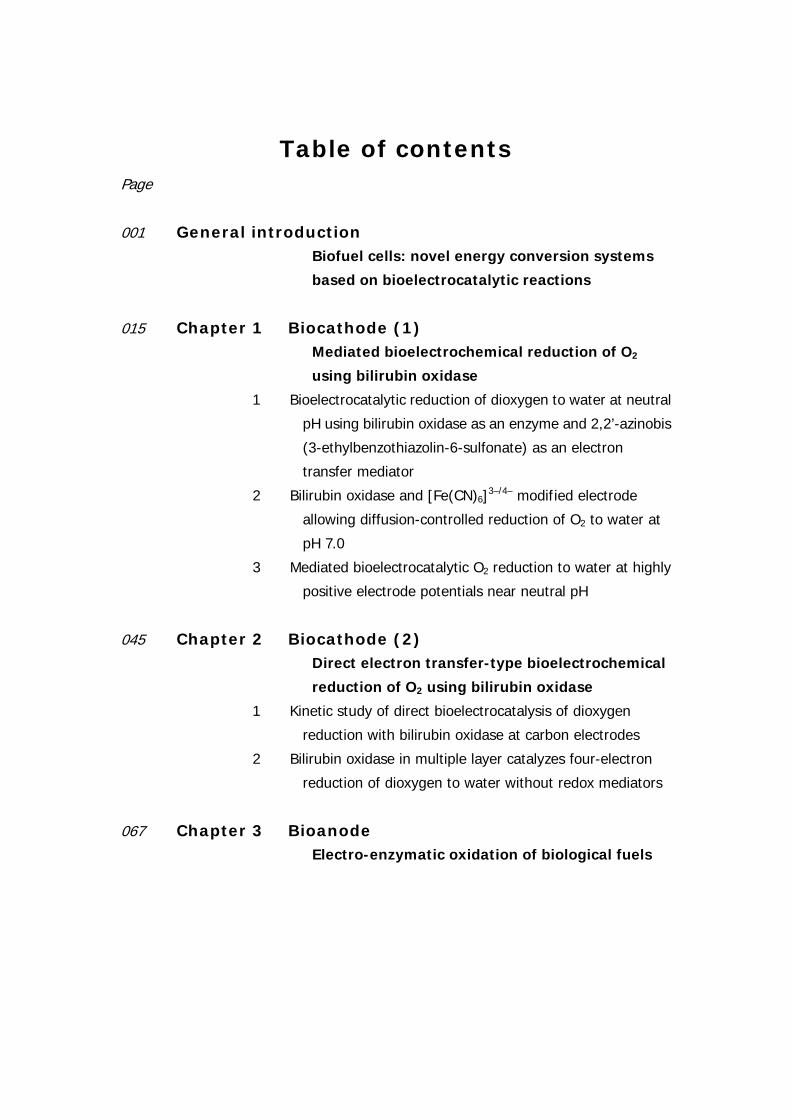
Table of contents Page
001 General introduction Biofuel cells: novel energy conversion systems
based on bioelectrocatalytic reactions
015 Chapter 1 Biocathode (1) Mediated bioelectrochemical reduction of O2
using bilirubin oxidase
1 Bioelectrocatalytic reduction of dioxygen to water at neutral
pH using bilirubin oxidase as an enzyme and 2,2’-azinobis
(3-ethylbenzothiazolin-6-sulfonate) as an electron
transfer mediator
2 Bilirubin oxidase and [Fe(CN)6]3–/4– modified electrode
allowing diffusion-controlled reduction of O2 to water at
pH 7.0
3 Mediated bioelectrocatalytic O2 reduction to water at highly
positive electrode potentials near neutral pH
045 Chapter 2 Biocathode (2) Direct electron transfer-type bioelectrochemical
reduction of O2 using bilirubin oxidase
1 Kinetic study of direct bioelectrocatalysis of dioxygen
reduction with bilirubin oxidase at carbon electrodes
2 Bilirubin oxidase in multiple layer catalyzes four-electron
reduction of dioxygen to water without redox mediators
067 Chapter 3 Bioanode Electro-enzymatic oxidation of biological fuels
Page
075 Chapter 4 Biofuel cell Bioelectrochemical energy conversion system
1 Bioelectrocatalysis-based dihydrogen/dioxygen fuel cell
operating at physiological pH
2 Photosynthetic bio -electrochemical ccell utilizing
cyanobacteria and water-generating oxidase
3 Glucose/O2 biofuel cell operating at physiological conditions
111 Chapter 5 Redox titration of redox proteins Development of a novel bulk electrolysis method
for in situ spectroscopic measurements
125 Appendix A Theory of bioelectrocatalytic current
135 Appendix B Review of biofuel cell (in Japanese)
154 Acknowledgments
155 List of publications
General introduction Biofuel cells: novel energy conversion systems based on bioelectrocatalytic reactions
1 Biological and electrical conversion of chemical energy
Living cells and organisms must perform work to stay alive, to grow, and to reproduce themselves. The ability to harness energy from a variety of metabolic pathways so to channel it into biological work is a fundamental property of all living organisms. Chemical energy is transferred within cells by ATP (adenosine 5'-triphosphate), which is primarily known in biochemistry as the "molecular currency" of intracellular energy transfer. For ATP to be synthesized in the cellular respiration from complex fuels, they first need to be broken down into their basic components, and then oxidized to CO2 concomitant with the reduction of NAD+ to NADH (and FAD to FADH2). The majority of ATP production by a non-photosynthetic aerobic eukaryote takes place in the mitochondria. In the mitochondria, it is the passage of electron pairs
b-c1Complex
Q
Cytochrome c
Inner membrane
Membrane
Outer membrane
NADHdehydrogenase
redo
x po
tent
ial (
mV
)
0
800
-400
400
Quinone
Cytochrome oxidase complex
NADH
NAD+
2H++1/2O2 H2O
redo
x po
tent
ial (
mV
)
0
800
-400
400
Electron flow
NADH
NAD+
2H++1/2O2 H2O
Proton flow
Figure 1. Electron and proton flows in respiration chain and biofuel cell.
1
INTRODUCTION
from NADH and FADH2 through the electron transport chain that powers the pumping of protons out of the mitochondrial matrix (outer membrane) and into the inner membrane space, which results in a proton motive force that is the net effect of a pH gradient and an electric potential gradient across the inner mitochondrial membrane (Figure 1, left). Flow of protons down the potential gradient provides the driving force for ATP synthesis by the protein complex ATP synthase. The chemical energy in fuels is transferred to ATP via proton motive force. The basic concept of biofuel cell is direct conversion of the fuel’s chemical energies to electricity using outer electronic circuit not proton circuit (Figure 1, right).
2 Basic concepts: biofuel cells directly convert fuel to electricity
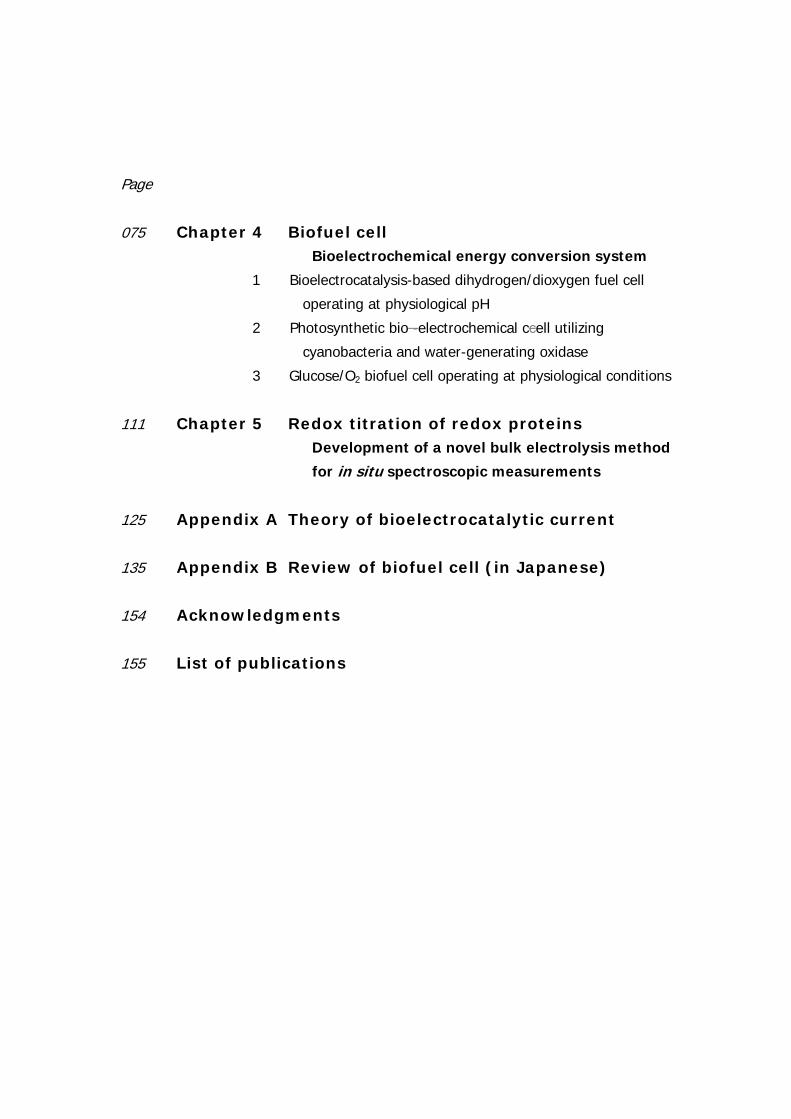
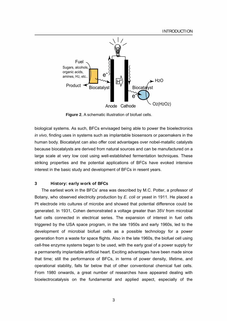
Biofuel cells (BFCs) utilize biocatalysts such as enzymes and microorganisms for the conversion of chemical energy into electrical energy in the one of two ways. Either (i) the biocatalysts can generate the fuel substrates, such as H2, methanol, and methane, for the fuel cell by biocatalytic transformations or metabolic processes, or (ii) the biocatalysts may participate in the electron transfer chain between the fuel substrates and the electrode surface. In this thesis, the author focused on the BFCs, which directly convert fuels to electricity, that is type (ii) (Figure 2). BFCs represent a new kind of energy-conversion technology that is distinct from conventional fuel cells, such as H2/O2 and methanol/O2 polyelectrolyte membrane-type fuel cells, mainly in that they can operate under moderate conditions, such as in mild media (near-neutral pH) and at ambient temperature (20 – 40 ºC). Moreover, compared with the noble-metal catalysts used in conventional fuel cells, the biocatalysts used in the BFCs are more efficient and selective to the fuel. Therefore, when anodic and cathodic biocatalysts are completely immobilized on each electrode, it prevents crossover reactions between anode and cathode, which allows one-compartment (and miniature) biofuel cells without separator. Also the variety of reactions able to be catalyzed by biocatalysts makes the use of much wider range of fuel substances possible. Abundant organic raw materials such as alcohols, organic acids, or sugars can be used as substrates for oxidation process, and O2 or H2O2 can act as the substrate being reduced. In principle, when one moles of glucose is completely converted to 6 moles of CO2 using the cascade enzymatic reactions, a process is capable of releasing 24 electrons and yields high capacity per weight as large as 3600 Ah kg–1. In case of ethanol, the capacity would increase up to 7000 Ah kg–1, the value being much higher than that of methanol. More remarkably, the biomass consumed by the BFCs, such as glucose and O2, is generally endogenous to
2
INTRODUCTION
O2(H2O2)
H2O
Fuel
Product
Sugars, alcohols,organic acids,amines, H2, etc.. e-
e-
H+
Biocatalyst
Anode Cathode
Biocatalyst
Figure 2. A schematic illustration of biofuel cells.
biological systems. As such, BFCs envisaged being able to power the bioelectronics in vivo, finding uses in systems such as implantable biosensors or pacemakers in the human body. Biocatalyst can also offer cost advantages over nobel-matallic catalysts because biocatalysts are derived from natural sources and can be manufactured on a large scale at very low cost using well-established fermentation techniques. These striking properties and the potential applications of BFCs have evoked intensive interest in the basic study and development of BFCs in resent years.
3 History: early work of BFCs
The earliest work in the BFCs’ area was described by M.C. Potter, a professor of Botany, who observed electricity production by E. coli or yeast in 1911. He placed a Pt electrode into cultures of microbe and showed that potential difference could be generated. In 1931, Cohen demonstrated a voltage greater than 35V from microbial fuel cells connected in electrical series. The expansion of interest in fuel cells triggered by the USA space program, in the late 1950s and early 1960s, led to the development of microbial biofuel cells as a possible technology for a power generation from a waste for space flights. Also in the late 1960s, the biofuel cell using cell-free enzyme systems began to be used, with the early goal of a power supply for a permanently implantable artificial heart. Exciting advantages have been made since that time; still the performance of BFCs, in terms of power density, lifetime, and operational stability, falls far below that of other conventional chemical fuel cells. From 1980 onwards, a great number of researches have appeared dealing with bioelectrocatalysis on the fundamental and applied aspect, especially of the
3
INTRODUCTION
second-generation amperometric biosensors. Nevertheless, recent development from 2000 showed a renewed interest in BFCs. The biocatalytic reduction of oxidizers has attracted much less attention than the biocatalytic oxidation of fuels. Nonetheless, in order to construct a biofuel cell element, it is essential to design a functional cathode for the reduction of the oxidizer that is coupled to the anode and allows the electrically balanced current flow. Conventional O2-reducing cathodes used in fuel cells are usually not compatible with biocatalytic anodes since high temperatures and pressures are applied for their operation. Thus, biocatalytic reductive processes at the cathode should be considered as a strategy to design all biomaterial-based functional fuel cells. BFC becomes to be considered as a general device for power generation. The author first emphasized the development of the bioelectrochemical reduction of O2 to water at neutral pH, and successfully achieved it (described in chapter 1 and 2). Therefore, recent studies have directed toward special and concrete applications such as implantable devices, sensors, drug delivery systems, microchips, and portable power supplies.
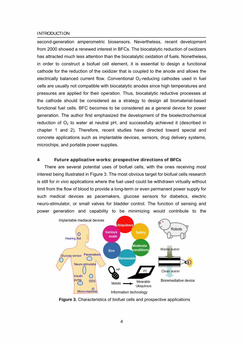
4 Future applicative works: prospective directions of BFCs
There are several potential uses of biofuel cells, with the ones receiving most interest being illustrated in Figure 3. The most obvious target for biofuel cells research is still for in vivo applications where the fuel used could be withdrawn virtually without limit from the flow of blood to provide a long-term or even permanent power supply for such medical devices as pacemakers, glucose sensors for diabetics, electric neuro-stimulator, or small valves for bladder control. The function of sensing and power generation and capability to be minimizing would contribute to the
Pacemakers
Insulinpump
Glucose sensor
Hearing Aid
DDS
Neuro-stimulator
Micro-machine
PCHP
WearableMobileUbiquitous
Clean water
Waste water
Bioremediative device
Robots
Implantable mediacal devicesUbiquitous
Safety
Moderateconditions
Renewable
Eco
Various scale
Information technology Figure 3. Characteristics of biofuel cells and prospective applications
4
INTRODUCTION
development drug delivery system (DDS). The living system where BFCs run is not restricted to the human body; for example, fresh vegetables, fruit, fish, and animals would be used for BFC system, since the oxygen and fuel required for their operation can conceivably be taken from their immediate environment. Theses power supplement would contribute to the development of the field of ubiquitous networks and computing.
Ex vivo proposed applications are various. The large scale is represented by proposed power recovery from waste streams with simultaneous remediation by bioelectrochemical means, or purely for power generation in remote areas, the medium scale by power generating systems for specialist applications such as the robot, and perhaps of greatest potential the small scale power generation to replace battery packs for consumer electronic goods such as laptop computers or mobile telephones. In the future, especially, there would arise a significant demand for power souse for the miniaturization and portability of computing and communications devices. BFCs would be a promising candidate because they can be small and light, and the fuel can be taken from familiar concentrated chemical energy sources (e.g., juices and alcohols).
The larger scale applications tend to be organism based and the smaller scale ones more likely to be enzymatic. In the case of enzymatic fuel cells, at least, the major barrier to any successful application is component lifetime, particularly in view of the limited enzyme lifetime and problems of electrode fouling/poisoning. Implantable medical devices need power supplies that will operate for extremely long durations, as maintenance would necessitate surgery.
Although, BFC would be used as multi-cell stacks to produce the desirable output voltage of 1 – 5 V, it would be difficult to keep its output against the rapid change. Hybrid devices combining fuel cells and rechargeable batteries or capacitors would be desired. One candidate is redox flow–type cells, in which energy can be stored in chemical form (resembling mediator) until the cell is discharged in BFC to generate current and power can be supplied to the cell to drive a charging set of reactions. A bio-redox flow cell has not yet been reported, but some reported BFC using mediator works as redox flow mechanism in principal.
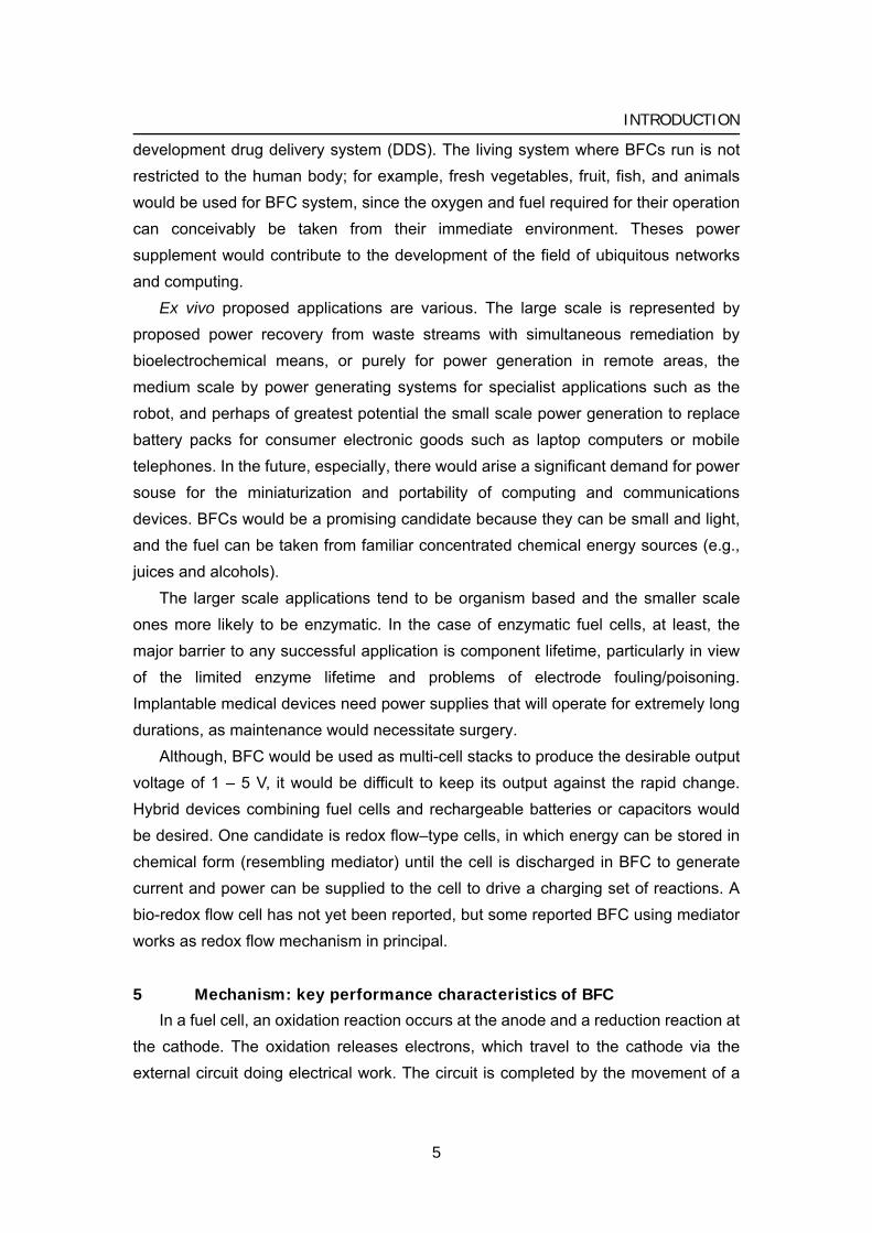
5 Mechanism: key performance characteristics of BFC
In a fuel cell, an oxidation reaction occurs at the anode and a reduction reaction at the cathode. The oxidation releases electrons, which travel to the cathode via the external circuit doing electrical work. The circuit is completed by the movement of a
5
INTRODUCTION
iRinner
Ec−Ea
Vcell
i
P
E
i
imax
Eo'fuel Eo'O2
Electrocatalytic oxidation of fuel
Electrocatalytic oxidation of O2
1 1
2
2ilimimax
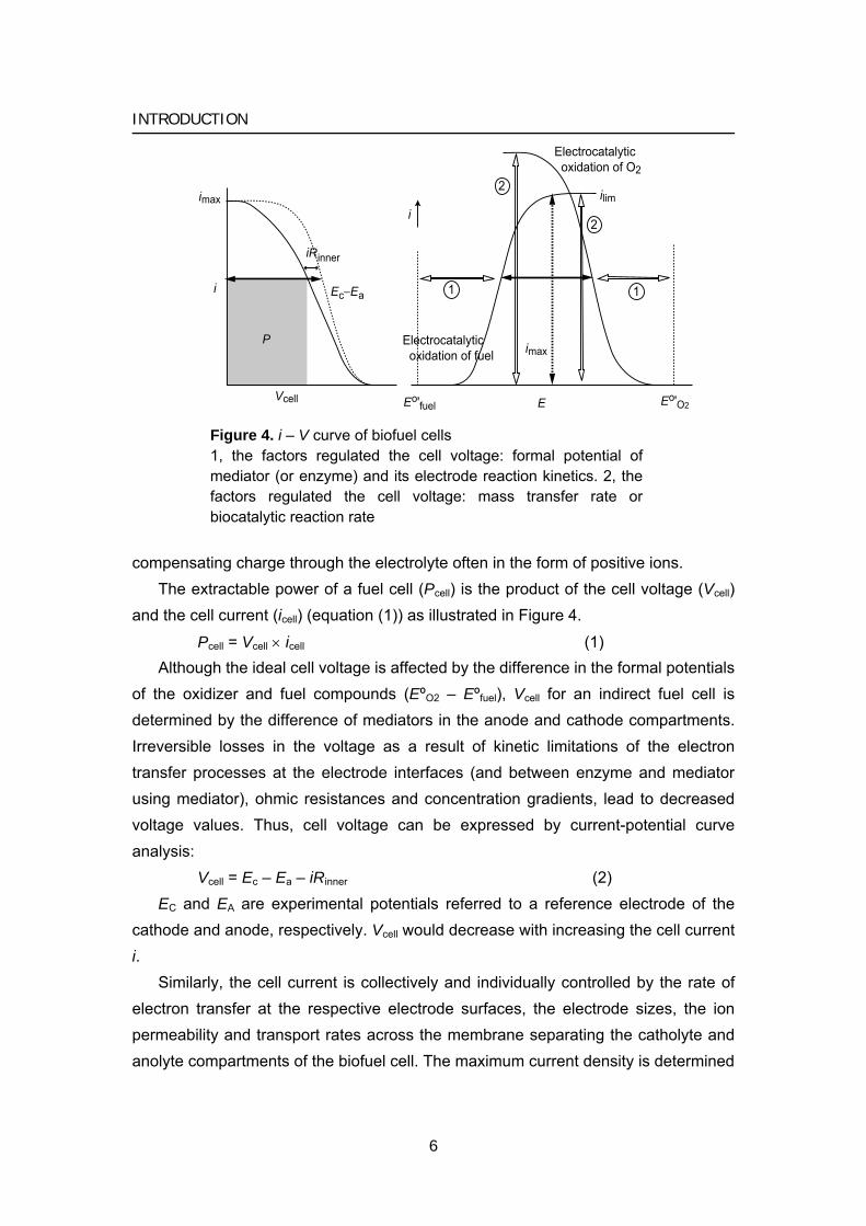
Figure 4. i – V curve of biofuel cells 1, the factors regulated the cell voltage: formal potential of mediator (or enzyme) and its electrode reaction kinetics. 2, the factors regulated the cell voltage: mass transfer rate or biocatalytic reaction rate
compensating charge through the electrolyte often in the form of positive ions. The extractable power of a fuel cell (Pcell) is the product of the cell voltage (Vcell)
and the cell current (icell) (equation (1)) as illustrated in Figure 4.
Pcell = Vcell × icell (1) Although the ideal cell voltage is affected by the difference in the formal potentials
of the oxidizer and fuel compounds (EºO2 – Eºfuel), Vcell for an indirect fuel cell is determined by the difference of mediators in the anode and cathode compartments. Irreversible losses in the voltage as a result of kinetic limitations of the electron transfer processes at the electrode interfaces (and between enzyme and mediator using mediator), ohmic resistances and concentration gradients, lead to decreased voltage values. Thus, cell voltage can be expressed by current-potential curve analysis:
Vcell = Ec – Ea – iRinner (2) EC and EA are experimental potentials referred to a reference electrode of the
cathode and anode, respectively. Vcell would decrease with increasing the cell current i.
Similarly, the cell current is collectively and individually controlled by the rate of electron transfer at the respective electrode surfaces, the electrode sizes, the ion permeability and transport rates across the membrane separating the catholyte and anolyte compartments of the biofuel cell. The maximum current density is determined
6
INTRODUCTION
by the surface biocatalytic reaction velocity, which is the product of surface concentration of biocatalyst and its kinetics. These different parameters collectively influence the biofuel cell power, and for improved efficiencies, the Vcell and icell values should be optimized. For example, to obtain an optimal voltage from a cell it is desirable to maximize the driving force (Ec – Ea) and to minimize the ohmic resistance losses, iRinner. The latter can be achieved through appropriate cell design considerations such as minimizing the inter-electrode gap or optimizing electrode configurations. Towards this goal, it is essential to tailor integrated enzyme-electrodes that exhibit electrical contact and communication with the conductive supports. The detailed characterization of the interfacial electron transfer rates, biocatalytic rate-constants and cell resistances is essential upon the construction of the biofuel cells. Identification of the rate-limiting steps allows then the development of strategies to improve and enhance the cell output.
6 Bioelectrochemical cells involving a whole organism
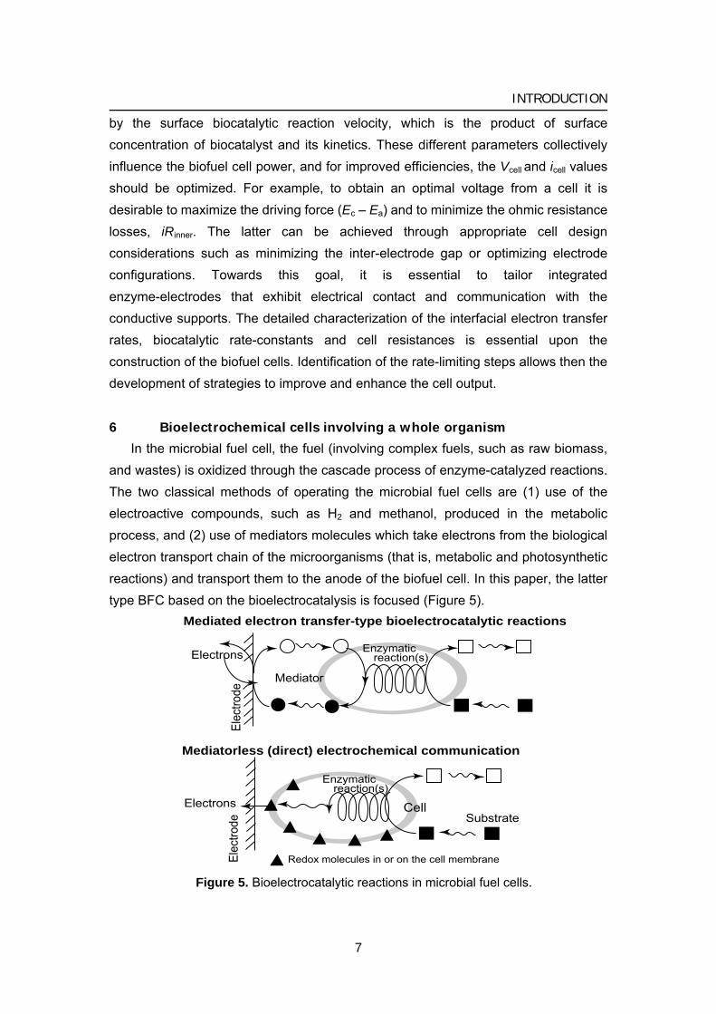
In the microbial fuel cell, the fuel (involving complex fuels, such as raw biomass, and wastes) is oxidized through the cascade process of enzyme-catalyzed reactions. The two classical methods of operating the microbial fuel cells are (1) use of the electroactive compounds, such as H2 and methanol, produced in the metabolic process, and (2) use of mediators molecules which take electrons from the biological electron transport chain of the microorganisms (that is, metabolic and photosynthetic reactions) and transport them to the anode of the biofuel cell. In this paper, the latter type BFC based on the bioelectrocatalysis is focused (Figure 5).
Mediatorless (direct) electrochemical communication
Cell
Enzymatic reaction(s)
Redox molecules in or on the cell membraneElec
trode
Electrons
Electrons
Elec
trode
Mediator
Enzymatic reaction(s)
Substrate
Mediated electron transfer-type bioelectrocatalytic reactions
Figure 5. Bioelectrocatalytic reactions in microbial fuel cells.
7
INTRODUCTION
In this case, the biocatalytic process performed in the microorganisms becomes different from the natural one since the electron flow goes to the anode instead of to a natural electron acceptor. Since the natural electron acceptor is usually more efficient, it can compete with the desired scheme, so it is usually removed from the system. In most cases, the microbiological system operates under anaerobic conditions (when O2 is removed from the system), allowing electron transport to the artificial electron relays and, finally, to the anode. Low molecular weight redox species may assist the shuttling of electrons between the intracellular bacterial space and an electrode.
However, there are many important requirements that such a mediator should satisfy in order to provide an efficient electron transport from the bacterial metabolites to the anode: (a) The oxidized state of the mediator should easily penetrate the membrane to reach the reductive species inside the bacterium. (b) The redox potential of the mediator should fit the potential of the reductive metabolite (the mediator potential should be positive enough to provide fast electron transfer from the metabolite, but it should not be so positive as to prevent significant loss of potential). (c) Neither oxidation state of the mediator should interfere with other metabolic processes. (d) The reduced state of the mediator should easily escape from the cell through the bacterial membrane. (e) The mediator should be chemically stable in the electrolyte solution, be well soluble, and not adsorb on the bacterial cells or electrode surface. (f) The electrochemical kinetics of the oxidation process of the mediator-reduced state at the electrode should be fast (electrochemically reversible). Many different organic and organometallic compounds have been tested in combination with bacteria to test the efficiency of mediated electron transport from the internal bacterial metabolites to the anode of a biofuel cell.
Photo-microbial fuel cells (photo-bioelectrochemical cells) using photosynthetic cyanobacterium have much in common with other microbial fuel cells, differing only in that the energy converted to electricity comes originally from a light source rather than a fuel substrate. The excited electrons by illumination may be extracted by a soluble mediator, such as quinones, transporting electrons to electrode. By combining photosynthetic anodic reaction, in which the oxidation of water to produce O2 and protons, and cathodic reaction of O2 reduction, a photo-microbial biofuel cell with no special fuel requirement can be produced (section 2 in chapter 4).
Mediatorless electron transfer in microbial biofuel cell system is achieved by culture of microbial cell, which belong to the group of Shewanella or Geobacter, on the electrode surface combined with an organism with electron transfer groups naturally incorporated into the cell membrane. Cytochromes, quinone compounds, or
8
INTRODUCTION
electrically conductive pilus-like appendages called bacterial nanowires are considered as the candidates for the electron transfer pathway from cells to anodes, however the details of electron transfer mechanism are not clear.
7 Biofuel cells utilizing a purified enzyme
Upon utilizing enzymes as catalytically active ingredients in biofuel, one may apply oxidative biocatalysts in the anodic compartments for the oxidation of the fuel-substrate and transfer of electrons to the anode, whereas reductive biocatalysts may participate in the reduction of the oxidizer in the cathodic compartment of the biofuel cell.
Redox enzyme is categorized into two groups by the view of bioelectrocatalytic reactions. The first group enzymes has nicotinamide adenine dinucleotide (NADH/NAD+) or nicotinamide adenine dinucleotide phosphate (NADPH/NADP+) redox centers, which are often weakly bound to the protein of the enzyme and diffuse away from the enzyme, acting as carriers of electrons. To complete the electron transfer to the electrode, produced NADH or NADPH should be oxidized at electrode without kinetic losses by using some suitable electrocatalyst including enzymes (diaphorase) (described in chapter 3).
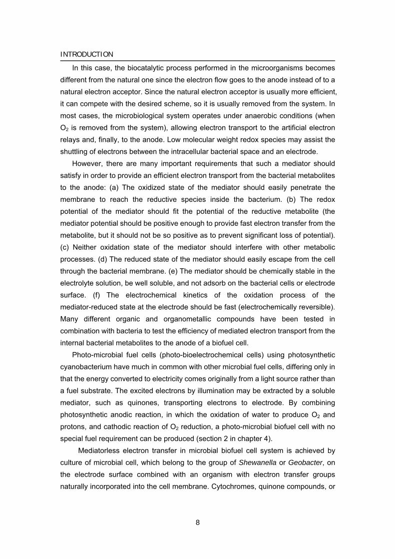
The other type of enzyme is the enzyme with a strongly bound redox center deeply bound in a protein or glycoprotein shell. In addition, enzymes in this group are classified into three types, peroxidases and dehydrogenase. Oxidases use dioxygen as electron acceptor and dioxygen is reduced to water or hydrogen peroxide.
Mediated electron transfer-type bioelectrocatalytic reactions
Direct electron transfer type bioelectrocatalytic reactions
Electrons
Ele
ctro
deE
lect
rode
Electrons
Mediator
Substrate
Enzyme
Figure 6. Enzymatic bioelectrocatalytic reactions.
9
INTRODUCTION
Peroxidases catalyze the oxidation of substrate by a hydrogen peroxide. Dehydrogenases catalyze the oxidation reaction of substrate by transferring one or more protons and a pair of electrons to an electron acceptor, except for dioxygen and peroxide. The enzyme-catalyzed reaction is characterized into two types from the view of bioelectrocatalytic electron transfer mechanisms: one is mediated electron transfer (MET) type and direct electron transfer (DET) type, where the enzymatic and electrode reactions are coupled by direct (mediatorless) electron transfer (Figure 6).
In MET, a low molecular weight, redox-active species, referred to as a mediator, is introduced to shuttle electrons between the enzyme active site and the electrode. In this case, the enzyme catalyzes the oxidation or reduction of the redox mediator. Therefore, the mediator acts as a substrate for the enzymatic reaction: for example, the electron-donating substrate in oxidase or peroxidase reactions, and the electron acceptor in the dehydrogenase reaction can be a mediator. The regeneration of the mediator occurs on the electrode surface preferably at low overvoltage (electrochemically reversible). The significant advantage of MET system is that this system can be applied to most of redox enzymes. In addition, the MET-type bioelectrocatalytic reaction offers the current density advantage over the DET-type one as long as the mediator concentration is sufficiently high describe in appendix A. Mediators can exist free in solution; physically entrapped behind a membrane; immobilized in a matrix along with the biocatalyst; immobilized on the surface of electrode; or covalently bound to a surface or polymer network, wherein the polymer can be conductive or insulating. Selected immobilization chemistries reported in relation to enzymatic biofuel cells are reviewed in the sections below (REF). Immobilization will also increase the surface concentration of mediators and enzymes, which may lead to an increase in the current density of bioelectrocatalysis.
However, the MET system has several disadvantages also. One of disadvantages is concerned with the thermodynamic loss, which is arisen from negative standard Gibbs energy change required for fast electron transfers between enzymes and mediators. The rate constant between enzymes and mediators increases exponentially with their formal potential difference (due to linear free energy relationship) in a series of compounds and tends to reach a constant value independent of the potential difference (due to microscopic diffusion control). In order to minimize the thermodynamic loss, one must select suitable mediators in view of thermodynamics and kinetics. Another disadvantage is that the system has high risk of mediator-leaking (or desorption) from electrodes, which causes serious crossover reactions: mediators desorbed from anodes will react at cathodes or vice versa,
10
INTRODUCTION
leading to a decrease in the cell power by merely converting the redox reaction energy into heat. In order to avoid the risky crossover, separators may be incorporated into biofuel cells, which would lose simplicity in structure of biofuel cells.
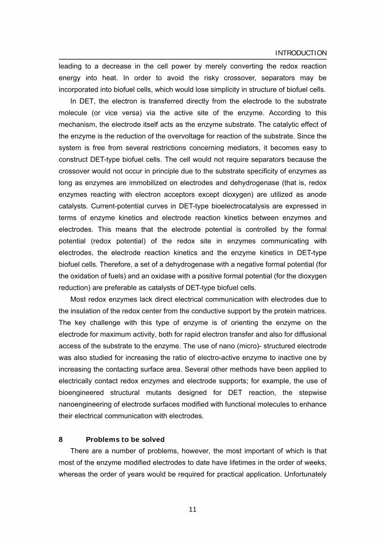
In DET, the electron is transferred directly from the electrode to the substrate molecule (or vice versa) via the active site of the enzyme. According to this mechanism, the electrode itself acts as the enzyme substrate. The catalytic effect of the enzyme is the reduction of the overvoltage for reaction of the substrate. Since the system is free from several restrictions concerning mediators, it becomes easy to construct DET-type biofuel cells. The cell would not require separators because the crossover would not occur in principle due to the substrate specificity of enzymes as long as enzymes are immobilized on electrodes and dehydrogenase (that is, redox enzymes reacting with electron acceptors except dioxygen) are utilized as anode catalysts. Current-potential curves in DET-type bioelectrocatalysis are expressed in terms of enzyme kinetics and electrode reaction kinetics between enzymes and electrodes. This means that the electrode potential is controlled by the formal potential (redox potential) of the redox site in enzymes communicating with electrodes, the electrode reaction kinetics and the enzyme kinetics in DET-type biofuel cells. Therefore, a set of a dehydrogenase with a negative formal potential (for the oxidation of fuels) and an oxidase with a positive formal potential (for the dioxygen reduction) are preferable as catalysts of DET-type biofuel cells.
Most redox enzymes lack direct electrical communication with electrodes due to the insulation of the redox center from the conductive support by the protein matrices. The key challenge with this type of enzyme is of orienting the enzyme on the electrode for maximum activity, both for rapid electron transfer and also for diffusional access of the substrate to the enzyme. The use of nano (micro)- structured electrode was also studied for increasing the ratio of electro-active enzyme to inactive one by increasing the contacting surface area. Several other methods have been applied to electrically contact redox enzymes and electrode supports; for example, the use of bioengineered structural mutants designed for DET reaction, the stepwise nanoengineering of electrode surfaces modified with functional molecules to enhance their electrical communication with electrodes.
8 Problems to be solved
There are a number of problems, however, the most important of which is that most of the enzyme modified electrodes to date have lifetimes in the order of weeks, whereas the order of years would be required for practical application. Unfortunately
11
INTRODUCTION
most of the biofuel cells described today would be capable of meeting demands for short term application only.
Although the stabilization of enzymes has been an active area for many years, the state-of-the-art is not capable of meeting the requirements of such devices. Suitable immobilization of enzymes would extend its lifetime as shown by practical bioreactors. It is probable that enzymes will have to be modified by routes such as genetic engineering if the required enzyme stabilities are to be met. In addition to that, it would be necessary to develop the screening test for the new enzyme suitable for the fuel cell.
Biofuel cell can exhibit higher operational voltage as described above. The current density is still small in the order of two or three compared with the conventional fuel cell or batteries, although hundreds or more current density compared with 10 years ago. It would be needed the further development of immobilization method using micro- (or nano-) structured material, and also the search for the new enzyme with much higher activity. An enzyme-electrode would encounter the problem of the mass transfer of fuels in the stage of obtaining the current density in the order of 100 mA cm–2 and more.
As for anodes in enzymatic fuel cells, most of the enzymatic reactions using solo enzyme are two electrons oxidation of reducing fuel. It would cause the accumulation of oxidized product. Cascade reaction constructed from the multiple reactions, such as citrate cycle and pentose phosphate cycle, would be needed to make a gaseous product, such as CO2, or insoluble product in order to easily exhaust from the system.
A problem for biomedical devices implanted that must be addressed is that of biocompatibility; the biofuel cell must be capable of existing in the physiological environment without an unacceptable degree of biofouling occurring over extended periods of time. Coating of biocompatible polymer, such as MPC polymer, to prevent the protein adsorption and fouling on the enzyme electrode.
9 Concluding remarks
During the 20th century, energy consumption increased dramatically and an unbalanced energy management exists. Every year, to construct the sustainable energy cycle, increasing attentions have been paid to the global energy, and the research into alternative renewable energy instead of petroleum. Fuel cells offer a possible solution to this problem, with the fuel needed for conventional cells usually being either hydrogen or methanol. Hydrogen is gaseous and this gives rise to storage and transport problems. Methanol also has a problem in safety. Many of the
12
INTRODUCTION
alternative fuels that could be used within fuel cells are still dependent on petroleum products and therefore offer few advantages.
Biofuel cells for the generation of electrical energy from abundant organic substrates can be organized by various approaches. All compounds to be utilized by living things such as sugars, alcohols, amines, organic acids and hydrogen and also, in principle, other variety of large molecular-weight biomasses are possible substances for biofuel cell. For example, if a molecule of glucose is oxidized completely to CO2 with O2 as the oxidant, there are 24 electrons available for current generation. Furthermore, the glucose is produced of photosynthesis, and then the process is carbon neutral, which clearly offers environmental benefits. One approach involves the use of microorganisms as biological reactors for the fermentation of raw materials to fuel products, e.g., hydrogen, that are delivered into a conventional fuel cell. A further methodology to develop biofuel cells involves the application of redox enzymes (microorganisms) for the targeted oxidation and reduction of specific fuel and oxidizer substrates at the electrode supports and the generation of the electrical power output. The development of biofuel cells for practical applications is a field which is still in its infancy, although there is unquestionably much potential for further improvement.
In future, one of the most active areas in the field is focused towards developing power sources for implantable devices within humans as the alternative use of lithium–iodine batteries in implantable devices such as pacemakers, pumps (e.g., insulin pumps), sensors and prosthetic units. Implanted biofuel cell would use a biological fuel source such as glucose or lactate, and O2, both of which are readily available in physiological fluids such as blood. Other possibilities for biofuel cell research include the future development of power supplies for use in remote areas. In an ideal scenario biofuel cells such as these should be capable of using readily available fuel sources. Plant saps, for example, often contain high levels of sugars, which could be used as a fuel. Many conventional hydrogen or alcohol fuel cells require expensive noble metal catalysts and moreover often require extreme conditions of pH or high temperature. Thus, disposable style maybe suitable for biofuel cells until enough stability can be secured. Microbial fuel cells may also in the future be used to help degrade organic waste such as sewage sludge (and also produce electricity). Problems of lifetime, stability and power density all need to be addressed, although the possible benefits of this technology are likely to drive continuing research. It needs to improve our knowledge of biocatalysis, electron processes at surfaces, biological and other material stability to realize this vision.
13
INTRODUCTION
14
10 References (review articles) S. C. Barton, J Gallaway and P. Atanassov, Chem. Rev., 104, 4867(2005). R. A. Bullen, T. C. Arnot, J. B. Lakeman and F. C. Walsh, Biosens. Bioelectron., 21,
2015 (2006). J. Kim, H. F. Jia, P. Wang, Biotechnol. Adv., 24, 296 (2006). G. T. R. Palmore, G. M. Whitesides, ACS Symp. Series No.556, 271 (1994). E. Katz, A. N. Shipway and I. Willner, in Handbook of Fuel Cells—Fundamentals,
Technology, Applications, ed. W. Vielstich, H. Gasteiger and A. Lamm, Wiley, vol. 1, pp. 355–381 (2003).
A. Heller, Phys. Chem. Chem. Phys., 6, 209 (2004).
1
Biocathode (1) Mediated bioelectrochemical reduction of O2 using bilirubin oxidase
Bioelectrocatalytic reduction of dioxygen to water at neutral pH using bilirubin oxidase as an enzyme and
2,2’-azinobis (3-ethylbenzothiazolin-6-sulfonate) as an electron transfer mediator
1
Electrochemical reduction of dioxygen to water proceeds very effectively at 0.4 V vs.
Ag|AgCl in pH 7.0 solution at an ambient temperature through the 2,2’-azinobis
(3-ethylbenzothiazoline-6-sulfonate) (ABTS2–)-mediated and bilirubin oxidase (BOD)
[EC 1.3.3.5]-catalyzed reaction of dioxygen. Electrochemistry of the ABTS2– oxidation
and the indirect catalytic reduction of dioxygen with ABTS2– and BOD have been
studied in detail to elucidate fully the bioelectrocatalytic behavior. The
bioelectrocatalytic system using a carbon felt electrode has been examined and
discussed in view of the cathode reaction in a biofuel cell.
Introduction
Electrochemical reduction of dioxygen to water without overvoltage has been a challenging subject in the field of fuel cell-related electrochemistry. Electrocatalysis using metal complexes [1, 2] and redox enzymes [3-9] has been studied to realize a fast electrochemical reduction of dioxygen at moderate temperatures under mild conditions. The author has been interested in the use of redox enzymes and microorganisms, because they are catalytically active under mild conditions, easily renewable, and free from environmental pollution. Laccase has been utilized as a biocatalyst for electrocatalytic reduction of dioxygen to water without a mediator
15
Chapter 1
compound [3, 4] and with 2,2’-azinobis (3-ethylbenzothiazolin-6-sulfonate) (ABTS2–) as a mediator [5]. The bioelectrocatalysis without mediator reported by Tarasevich et al. appears to be attractive because of the operation with a low overpotential, but extensive data obtained under fully specified experimental conditions are lacking [3]. Anson et al. have studied extensively the laccase-catalyzed electrolytic reduction of dioxygen and revealed that the reaction proceeds at about 0.5 V vs. SCE at pH lower than 5.5 [4]. More recently, Yaropolov et al. have investigated bioelectrocatalysis for dioxygen reduction based on direct electron transfer between carbon electrodes and copper-containing enzymes (laccase, tyrosinase, ascorbate oxidase and ceruloplasmin) [6]. Palmore et al. have reported bioelectrocatalysis of laccase with ABTS2– as a mediator to demonstrate that the bioelectrocatalytic reduction of dioxygen occurs at about 0.5 V vs. SCE at pH 4.0 [5]. The same system using laccase from different origin has also been reported by Bourbonnais et al. [7]. The author has demonstrated that whole cells of Thiobacillus ferrooxidans function as effective biocatalyts to produce a cathodic current at about 0.3 V vs. Ag|AgCl at pH 2.0 for the bioelectrocatalytic reduction of dioxygen to water [8]. It is noted that these reactions proceed under acidic conditions. Considering that biocatalytic anodic oxidation of such substrates as glucose [9, 10], NADH [9, 11, 12], methanol [12], ethanol [13] and hydrogen [8, 14, 15], which can serve as an anodic reaction in a biofuel cell system, proceeds at around pH 7.0, the author needs to operate the cathodic reaction under neutral conditions. Bioelectrocatalytic reduction of dioxygen at pH 7.0 has been realized by a combination of cytochrome c and cytochrome oxidase, but the reduction occurs at a less positive potential, 0.0 V vs. SCE [16-18].
Bilirubin oxidase (BOD) [EC 1.3.3.5, from Myrothecium verrucaria] catalyzes the oxidation of bilirubin to biliverdin [19]. It has molecular mass of 60 kDa and is a multi-copper oxidase containing type 1, type 2, and type 3 coppers (in the ratio 1:1:2) similar to laccase, ascorbate oxidase, and ceruloplasmin [20-23]. It has been reported that BOD can catalyze the oxidation of ABTS2– and syringaldazine with dioxygen at the optimum pH 4.0 and 8.0, respectively [24]. The author has examined BOD as a catalyst for the ABTS2–-mediated bioelectrocatalytic reduction of dioxygen to water and found that the system allows electrocatalytic reduction of dioxygen at 0.5 V vs. Ag|AgCl at pH 7.0. This paper describes the details of the bioelectrocatalytic behavior at pH 7.0. The bioelectrocatalytic reduction of dioxygen with a carbon felt electrode is also examined to characterize the bulk electrolytic behavior of the reaction.
16
BIOCATHODE (MET)
Experimental
Materials Bilirubin oxidase (BOD, Amano, lot No. BOV02512) [EC 1.3.3.5] from
Myrothecium verrucaria was obtained from Amano Pharmaceutical Co. Japan. The concentration of bilirubin oxidase in a stock solution was determined spectrophotometrically using ε600 = 4800 M–1 cm–1 [23]. 2,2’-Azinobis (3-ethylbenzothiazoline-6-sulfonate) diammonium salt was purchased from Sigma Chemical Co. and used without further purification. All other chemicals used were of reagent grade.
Apparatus, electrodes, and electrochemical measurements Cyclic voltammetry and chronoamperometry were performed using a
Bioanalytical systems (BAS) CV-50W electrochemical analyzer. A glassy carbon
electrode with φ = 3.0 mm (BAS, No. 11-2013) was used as the working electrode. A platinum disk and Ag|AgCl|KCl(sat.) were used as the counter and reference electrode, respectively. A homemade one-compartment electrolysis cell with the solution volume of 1 cm3 was used. A glassy carbon electrode modified with immobilized BOD was prepared by the method reported previously [11]. In brief, 10 μL aliquot of the BOD solution (50 mg BOD mL–1) was dropped onto the surface of a glassy carbon electrode with a surface area of 0.07 cm2. After the solvent was allowed to evaporate at room temperature, the electrode was covered with a dialysis membrane having a thickness of 20 μm in the dry state. The BOD-modified electrode
was stored at 4 °C in pH 7.0 phosphate buffer when not in use. Bulk electrolysis and chronamperometry were carried out using a carbon felt sheet (TORAY Co., 1.5 cm × 1.5 cm × 1.0 mm) as the working electrode in an H-type electrolysis cell separated from the counter electrode with a sintered glass disc and a KCl salt bridge tube. Potentiometery with the carbon felt electrode was performed on an Advantest R6450 digital voltmeter (Tokyo, Japan). Dioxygen concentration was measured with a Clark-type oxygen electrode (Oriental Electronics, two-electrode system). All measurements were carried out in a phosphate buffer of pH 7.0 with ionic strength 0.1 (adjusted with KCl) at 25 ºC unless stated otherwise. The concentration of oxygen in pure water saturated with air is calculated to be 254 μM from the solubility data of
oxygen at 25 °C [25]. Solubility in an aqueous solution is somewhat different from that in pure water and depends on the kind and concentration of the salt present [25]. The salt effect has been corrected by taking the ratio of the limiting current at an oxygen electrode in pure water to that in the buffer solution; the oxygen concentration in the
17
Chapter 1
buffer saturated with air was determined to be 248 μM. All potentials are referred to the Ag|AgCl|KCl(sat.) electrode.
Results and discussion
Electrochemical behavior of ABTS2– in pH 7.0 phosphate buffer 2,2’-Azinobis (3-ethylbenzothiazoline-6-sulfonate) (ABTS2–) produced
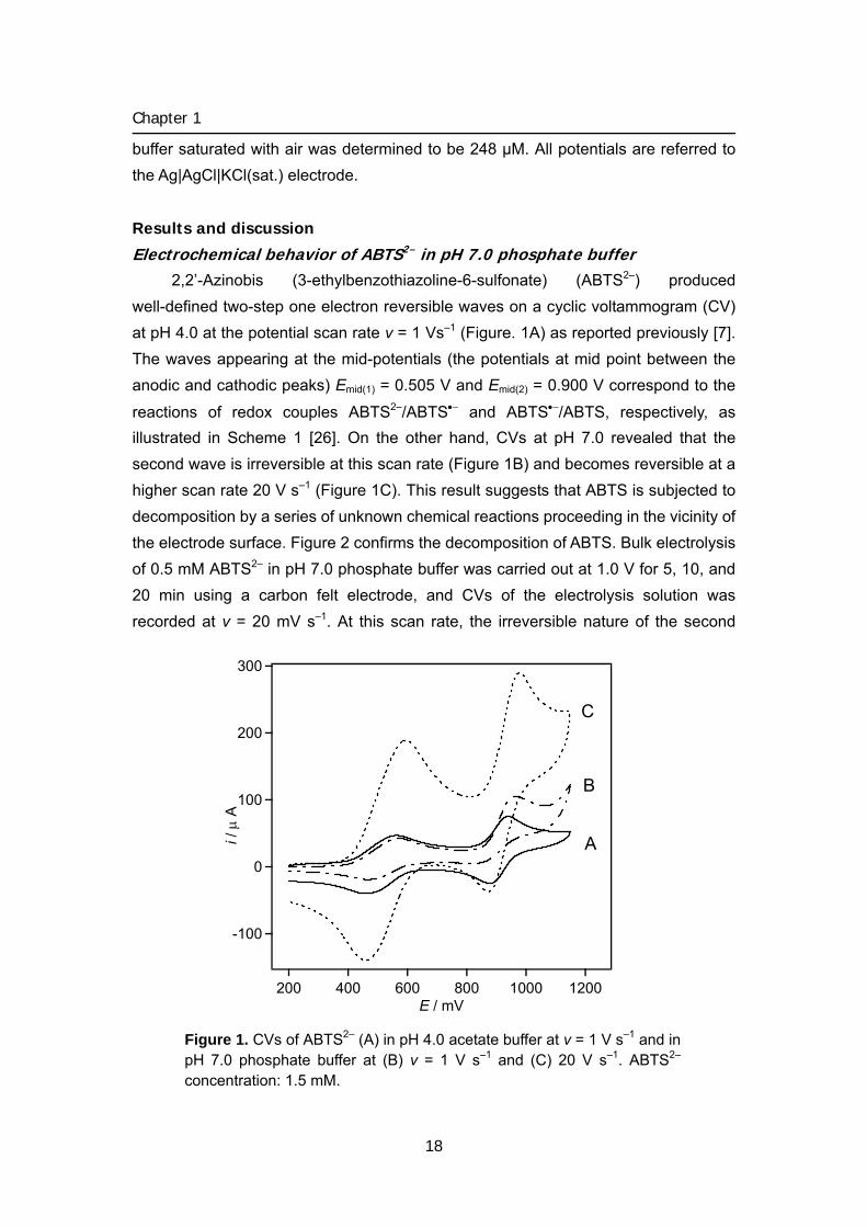
well-defined two-step one electron reversible waves on a cyclic voltammogram (CV) at pH 4.0 at the potential scan rate v = 1 Vs–1 (Figure. 1A) as reported previously [7]. The waves appearing at the mid-potentials (the potentials at mid point between the anodic and cathodic peaks) Emid(1) = 0.505 V and Emid(2) = 0.900 V correspond to the
reactions of redox couples ABTS2–/ABTS•− and ABTS•−/ABTS, respectively, as illustrated in Scheme 1 [26]. On the other hand, CVs at pH 7.0 revealed that the second wave is irreversible at this scan rate (Figure 1B) and becomes reversible at a higher scan rate 20 V s–1 (Figure 1C). This result suggests that ABTS is subjected to decomposition by a series of unknown chemical reactions proceeding in the vicinity of the electrode surface. Figure 2 confirms the decomposition of ABTS. Bulk electrolysis of 0.5 mM ABTS2– in pH 7.0 phosphate buffer was carried out at 1.0 V for 5, 10, and 20 min using a carbon felt electrode, and CVs of the electrolysis solution was recorded at v = 20 mV s–1. At this scan rate, the irreversible nature of the second
300
200
100
0
-100
i / μ
A
12001000800600400200E / mV
A
B
C
Figure 1. CVs of ABTS2– (A) in pH 4.0 acetate buffer at v = 1 V s–1 and in pH 7.0 phosphate buffer at (B) v = 1 V s–1 and (C) 20 V s–1. ABTS2– concentration: 1.5 mM.
18
BIOCATHODE (MET)
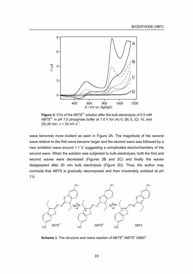
wave becomes more evident as seen in Figure 2A. The magnitude of the second wave relative to the first wave became larger and the second wave was followed by a new oxidation wave around 1.1 V, suggesting a complicated electrochemistry of the second wave. When the solution was subjected to bulk electrolysis, both the first and second waves were decreased (Figures 2B and 2C) and finally the waves disappeared after 20 min bulk electrolysis (Figure 2D). Thus, the author may conclude that ABTS is gradually decomposed and then irreversibly oxidized at pH 7.0.
8
6
4
2
0
i / μ
A
12001000800600400E / mV vs. Ag|AgCl
A
B
C
D
Figure 2. CVs of the ABTS2– solution after the bulk electrolysis of 0.5 mM ABTS2– in pH 7.0 phosphate buffer at 1.0 V for (A) 0, (B) 5, (C) 10, and (D) 20 min. v = 20 mV s-1.
Scheme 1. The structure and redox reaction of ABTS2–/ABTS•−/ABST
19
Chapter 1
-4
-2
0
2
4
i / μ
A
700600500400300E / mV vs. Ag|AgCl
v / mV s−1
20010050
20105
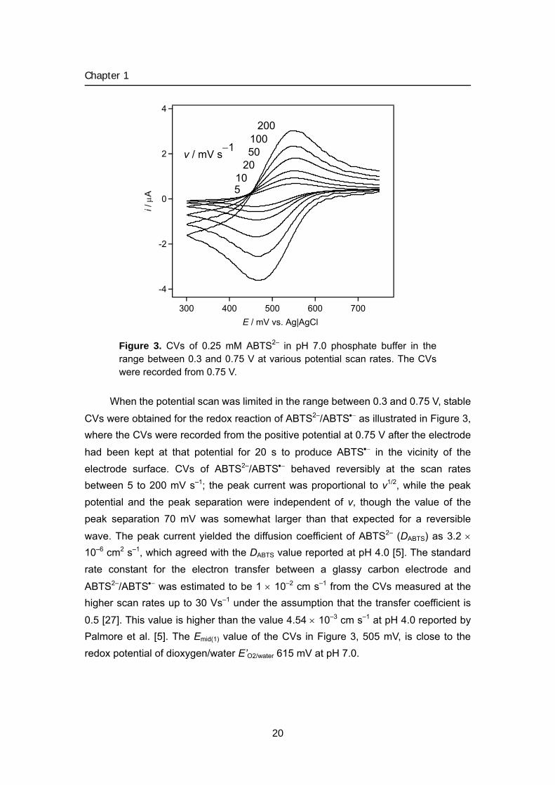
Figure 3. CVs of 0.25 mM ABTS2– in pH 7.0 phosphate buffer in the range between 0.3 and 0.75 V at various potential scan rates. The CVs were recorded from 0.75 V.
When the potential scan was limited in the range between 0.3 and 0.75 V, stable
CVs were obtained for the redox reaction of ABTS2–/ABTS•− as illustrated in Figure 3, where the CVs were recorded from the positive potential at 0.75 V after the electrode
had been kept at that potential for 20 s to produce ABTS•− in the vicinity of the electrode surface. CVs of ABTS2–/ABTS•− behaved reversibly at the scan rates between 5 to 200 mV s–1; the peak current was proportional to v1/2, while the peak potential and the peak separation were independent of v, though the value of the peak separation 70 mV was somewhat larger than that expected for a reversible
wave. The peak current yielded the diffusion coefficient of ABTS2– (DABTS) as 3.2 × 10⁻⁶ cm2 s–1, which agreed with the DABTS value reported at pH 4.0 [5]. The standard rate constant for the electron transfer between a glassy carbon electrode and
ABTS2–/ABTS•− was estimated to be 1 × 10⁻² cm s–1 from the CVs measured at the higher scan rates up to 30 Vs–1 under the assumption that the transfer coefficient is
0.5 [27]. This value is higher than the value 4.54 × 10⁻³ cm s–1 at pH 4.0 reported by Palmore et al. [5]. The Emid(1) value of the CVs in Figure 3, 505 mV, is close to the redox potential of dioxygen/water E’O2/water 615 mV at pH 7.0.
20
BIOCATHODE (MET)
-3
-2
-1
0
1
I / μ
A
700600500400300200E / mV
A
B
C
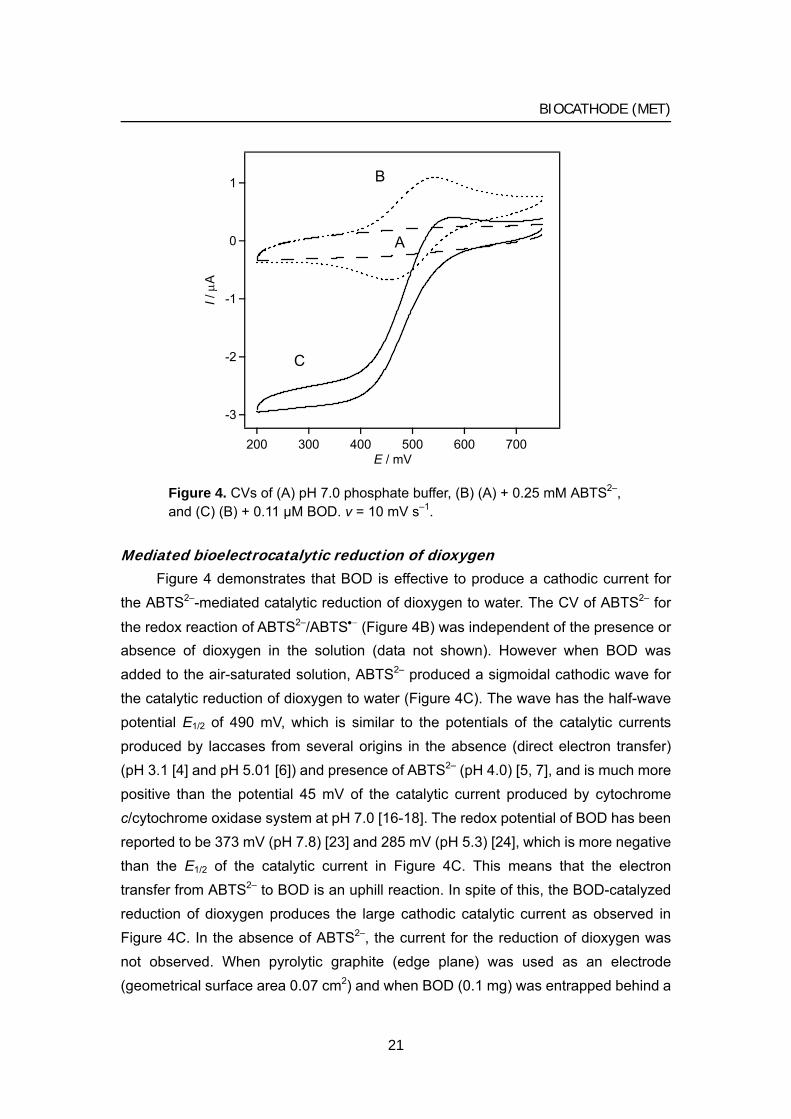
Figure 4. CVs of (A) pH 7.0 phosphate buffer, (B) (A) + 0.25 mM ABTS2–, and (C) (B) + 0.11 μM BOD. v = 10 mV s–1.
Mediated bioelectrocatalytic reduction of dioxygen Figure 4 demonstrates that BOD is effective to produce a cathodic current for
the ABTS2–-mediated catalytic reduction of dioxygen to water. The CV of ABTS2– for
the redox reaction of ABTS2–/ABTS•− (Figure 4B) was independent of the presence or absence of dioxygen in the solution (data not shown). However when BOD was added to the air-saturated solution, ABTS2– produced a sigmoidal cathodic wave for the catalytic reduction of dioxygen to water (Figure 4C). The wave has the half-wave potential E1/2 of 490 mV, which is similar to the potentials of the catalytic currents produced by laccases from several origins in the absence (direct electron transfer) (pH 3.1 [4] and pH 5.01 [6]) and presence of ABTS2– (pH 4.0) [5, 7], and is much more positive than the potential 45 mV of the catalytic current produced by cytochrome c/cytochrome oxidase system at pH 7.0 [16-18]. The redox potential of BOD has been reported to be 373 mV (pH 7.8) [23] and 285 mV (pH 5.3) [24], which is more negative than the E1/2 of the catalytic current in Figure 4C. This means that the electron transfer from ABTS2– to BOD is an uphill reaction. In spite of this, the BOD-catalyzed reduction of dioxygen produces the large cathodic catalytic current as observed in Figure 4C. In the absence of ABTS2–, the current for the reduction of dioxygen was not observed. When pyrolytic graphite (edge plane) was used as an electrode (geometrical surface area 0.07 cm2) and when BOD (0.1 mg) was entrapped behind a
21
Chapter 1
dialysis membrane on the electrode surface, a very small cathodic current started to appear from 0.4 V in an air-saturated buffer at v = 10 mV s-1, the magnitude being 15 nA at 0.2 V.
An empirical equation has been derived for the steady-state catalytic current IS of a mediated bioelectrocatalysis [28], which can be written in the present case by
fK
kDnFAi ]ABTS[
]/2ABTS[BOD][ 2
2ABTS
catABTSs
−−
•
+= (1)
with
( ) ( ) ⎥
⎥⎦
⎤
⎢⎢⎣
⎡
+++=
−−
−
17.9][ABTS 11.4][ABTS 0.848
][ABTS
ABTS22
ABTS2
ABTS2
KK
Kf 1
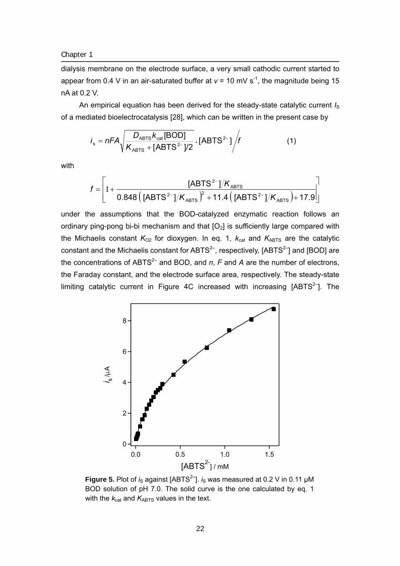
under the assumptions that the BOD-catalyzed enzymatic reaction follows an ordinary ping-pong bi-bi mechanism and that [O2] is sufficiently large compared with the Michaelis constant KO2 for dioxygen. In eq. 1, kcat and KABTS are the catalytic constant and the Michaelis constant for ABTS2–, respectively, [ABTS2–] and [BOD] are the concentrations of ABTS2– and BOD, and n, F and A are the number of electrons, the Faraday constant, and the electrode surface area, respectively. The steady-state limiting catalytic current in Figure 4C increased with increasing [ABTS2–]. The
8
6
4
2
0
i s /μ
A
1.51.00.50.0
[ABTS2-] / mM
Figure 5. Plot of iS against [ABTS2–]. iS was measured at 0.2 V in 0.11 μM BOD solution of pH 7.0. The solid curve is the one calculated by eq. 1 with the kcat and KABTS values in the text.
22
BIOCATHODE (MET)
dependence of iS on [ABTS2–] in Figure 5 obtained by chronoamperometry was
analyzed by eq. 1 with DABTS = 3.2 × 10⁻⁶ cm2 s–1and [BOD] = 0.11 μM to give the kcat value as 8.2 × 10² s–1 and KABTS value as 11 μM using non-linear curve fitting. The solid curve is the one calculated by eq 1 with the kcat and KABTS values.
The dependence of the BOD-catalyzed reaction on the concentration of dioxygen was studied by an ordinary method of measuring dioxygen consumption rate with a Clark-type oxygen electrode under the conditions [BOD] = 11 nM, [ABTS2–] = 250 μM, and [O2] = 10 to 248 μM. Analysis of the results by an ordinary
Michelis-Menten type equation yielded the values of KO2 = 51 μM and kcat = 2.3 × 10² s-1. The KO2 value confirms that the condition [O2] >> KO2 assumed in eq. 1 is satisfied in air-saturated solution, and the kcat value, as requested, is in fair agreement with that determined above from the data in Figure 5. From these data, the author can calculate the bimolecular rate constants, kcat/KABTS for the reaction between ABTS2–
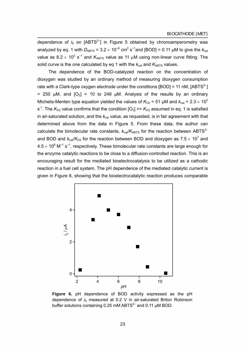
and BOD and kcat/KO2 for the reaction between BOD and dioxygen as 7.5 × 10⁷ and 4.5 × 10⁶ M–1 s–1, respectively. These bimolecular rate constants are large enough for the enzyme catalytic reactions to be close to a diffusion-controlled reaction. This is an encouraging result for the mediated bioelectrocatalysis to be utilized as a cathodic reaction in a fuel cell system. The pH dependence of the mediated catalytic current is given in Figure 6, showing that the bioelectrocatalytic reaction produces comparable
4
2
0
i s / μ
A
108642pH
Figure 6. pH dependence of BOD activity expressed as the pH dependence of iS measured at 0.2 V in air-saturated Briton Robinson buffer solutions containing 0.25 mM ABTS2– and 0.11 μM BOD.
23
Chapter 1
magnitudes of the current in the range between pH 4.0 and 7.5. The catalytic current also depended on the ionic strength of the solution adjusted with KCl; it decreased to 45% with the increase in ionic strength from 0.1 to 0.2, and to 30% and 25% at the ionic strength of 0.3 and 0.4, respectively. The catalytic current remained unchanged in magnitude for more than 120 h when the current was measured periodically at 24 h interval with the glassy carbon electrode modified with immobilized BOD, which was prepared by the method described in Experimental section.
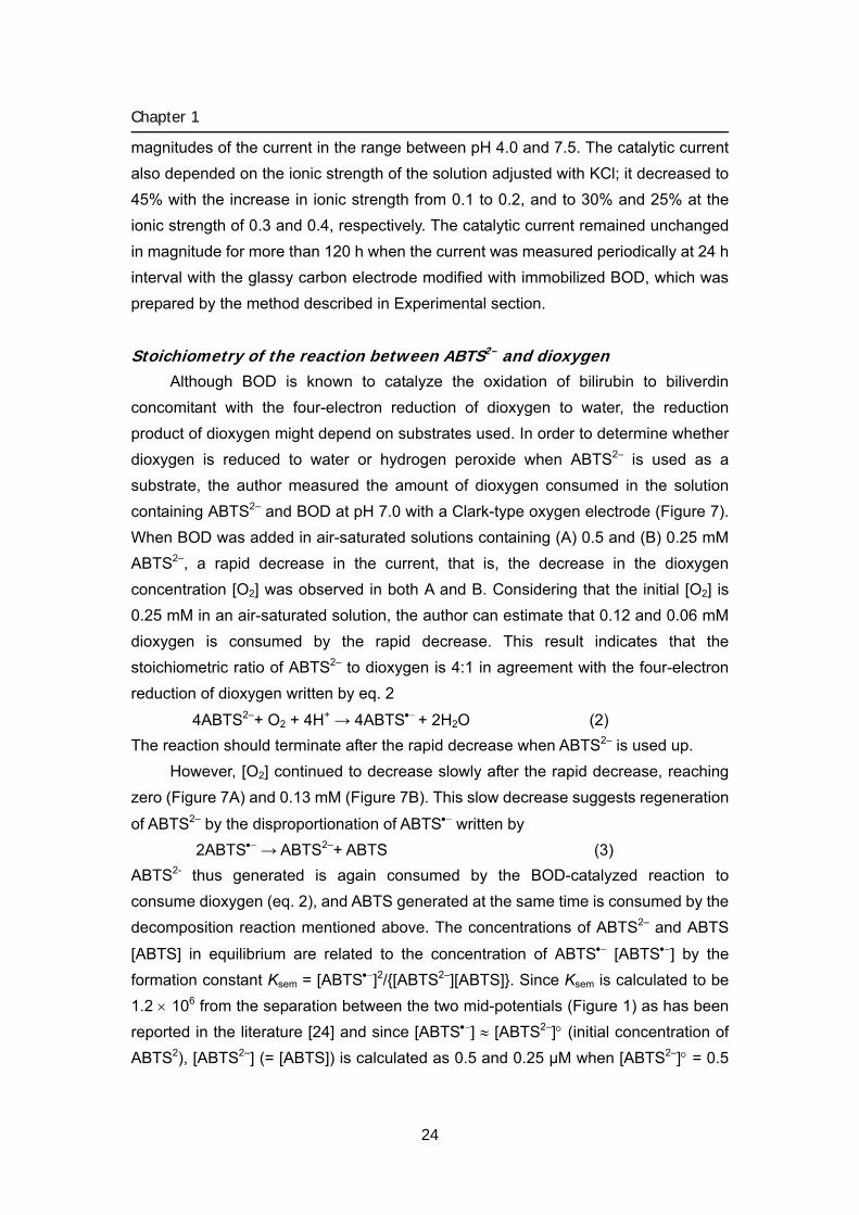
Stoichiometry of the reaction between ABTS2– and dioxygen Although BOD is known to catalyze the oxidation of bilirubin to biliverdin
concomitant with the four-electron reduction of dioxygen to water, the reduction product of dioxygen might depend on substrates used. In order to determine whether dioxygen is reduced to water or hydrogen peroxide when ABTS2– is used as a substrate, the author measured the amount of dioxygen consumed in the solution containing ABTS2– and BOD at pH 7.0 with a Clark-type oxygen electrode (Figure 7). When BOD was added in air-saturated solutions containing (A) 0.5 and (B) 0.25 mM ABTS2–, a rapid decrease in the current, that is, the decrease in the dioxygen concentration [O2] was observed in both A and B. Considering that the initial [O2] is 0.25 mM in an air-saturated solution, the author can estimate that 0.12 and 0.06 mM dioxygen is consumed by the rapid decrease. This result indicates that the stoichiometric ratio of ABTS2– to dioxygen is 4:1 in agreement with the four-electron reduction of dioxygen written by eq. 2
4ABTS2–+ O2 + 4H+ → 4ABTS•− + 2H2O (2) The reaction should terminate after the rapid decrease when ABTS2– is used up.
However, [O2] continued to decrease slowly after the rapid decrease, reaching zero (Figure 7A) and 0.13 mM (Figure 7B). This slow decrease suggests regeneration
of ABTS2– by the disproportionation of ABTS•− written by 2ABTS•− → ABTS2–+ ABTS (3)
ABTS2- thus generated is again consumed by the BOD-catalyzed reaction to consume dioxygen (eq. 2), and ABTS generated at the same time is consumed by the decomposition reaction mentioned above. The concentrations of ABTS2– and ABTS
[ABTS] in equilibrium are related to the concentration of ABTS•− [ABTS•−] by the formation constant Ksem = [ABTS•−]2/[ABTS2–][ABTS]. Since Ksem is calculated to be 1.2 × 10⁶ from the separation between the two mid-potentials (Figure 1) as has been reported in the literature [24] and since [ABTS•−] ≈ [ABTS2–]° (initial concentration of ABTS2), [ABTS2–] (= [ABTS]) is calculated as 0.5 and 0.25 μM when [ABTS2–]° = 0.5
24
BIOCATHODE (MET)
0.2
0.1
0.0
[O2]
/ m
M
150100500t / min
B
A
BOD
Figure 7. Time courses of dioxygen consumption in air-saturated (A) 0.50 and (B) 0.25 mM ABTS2- solutions measured with an oxygen electrode. BOD was added to the solutions at the point indicated by the arrow to make the solution 0.11 μM in BOD.
and 0.25 mM, respectively. The actual [ABTS2–] may be around the calculated [ABTS2–] values, though they will depend on the relative rate of the BOD-catalyzed reaction to that of the decomposition reaction. The calculated [ABTS2–] values are small enough for the BOD-catalyzed reaction rate to be written by VBOD = (kcat/KABTS)[BOD][ABTS2–]. In satisfying with this equation, the initial slope of the time
course in the slow decay in Figure 7 is proportional to [ABTS2–]°, which is presumed to determine the actual [ABTS2–] as mentioned.
The BOD-catalyzed reaction terminates when the consumption of the total
amount of ABTS2– [ABTS2–]° is completed by the decomposition reaction of ABTS through the disproportionation reaction. The final stoichiometry of the reaction between ABTS2- and dioxygen is given by the sum of eq. 2 and eq. 3:
2ABTS2– + O2 + 4H+ → 2ABTS + 2H2O (4) Eq. 4 explains the final [O2] close to zero mM in Figure 7A (0.5 mM ABTS2–) and of 0.13 mM in Figure 7B (0.25 mM ABTS2–). The time courses in Figure 7 were not affected by the addition of catalase catalyzing the reaction: 2 H2O2 → 2 H2O + O2 (data not shown), assuring that H2O2 was not produced during the BOD-catalyzed
25
Chapter 1
reaction.
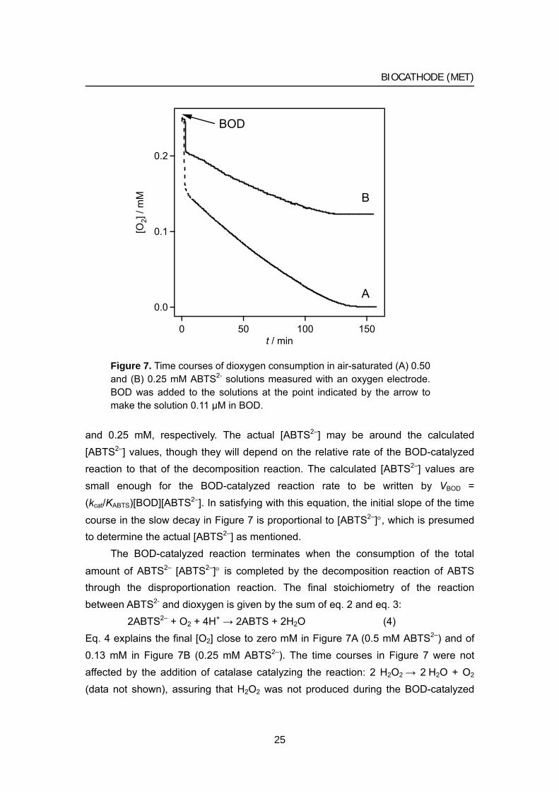
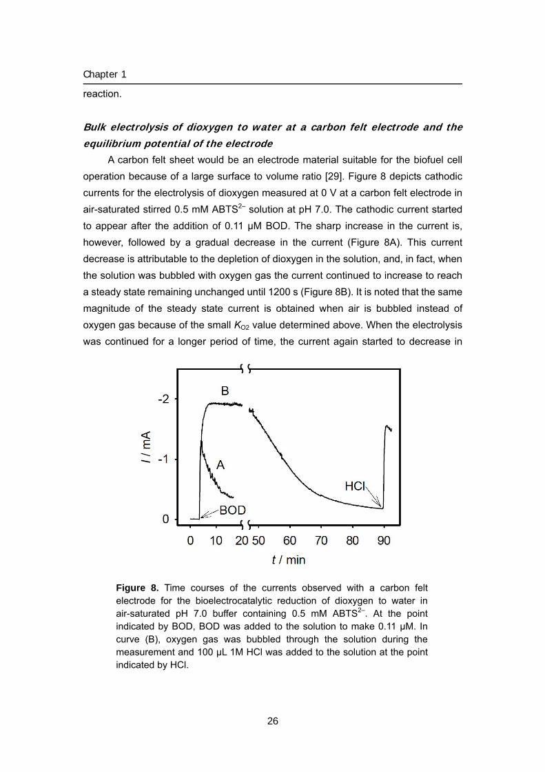
Bulk electrolysis of dioxygen to water at a carbon felt electrode and the equilibrium potential of the electrode
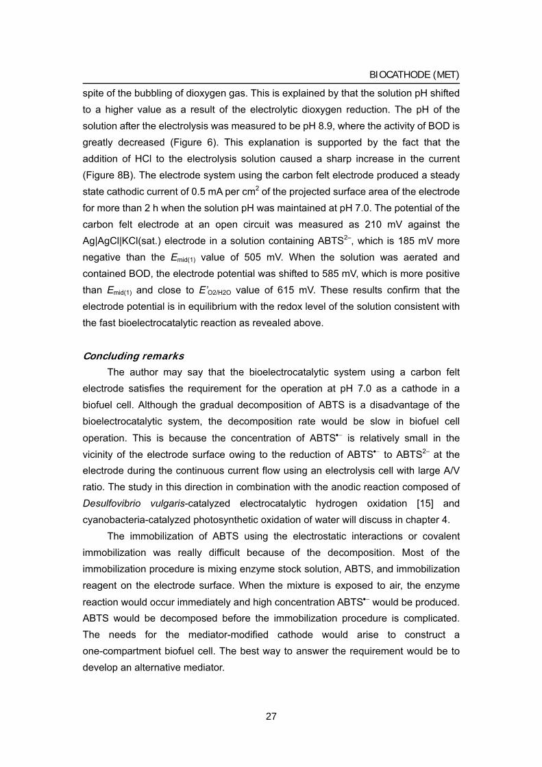
A carbon felt sheet would be an electrode material suitable for the biofuel cell operation because of a large surface to volume ratio [29]. Figure 8 depicts cathodic currents for the electrolysis of dioxygen measured at 0 V at a carbon felt electrode in air-saturated stirred 0.5 mM ABTS2– solution at pH 7.0. The cathodic current started to appear after the addition of 0.11 μM BOD. The sharp increase in the current is, however, followed by a gradual decrease in the current (Figure 8A). This current decrease is attributable to the depletion of dioxygen in the solution, and, in fact, when the solution was bubbled with oxygen gas the current continued to increase to reach a steady state remaining unchanged until 1200 s (Figure 8B). It is noted that the same magnitude of the steady state current is obtained when air is bubbled instead of oxygen gas because of the small KO2 value determined above. When the electrolysis was continued for a longer period of time, the current again started to decrease in
Figure 8. Time courses of the currents observed with a carbon felt electrode for the bioelectrocatalytic reduction of dioxygen to water in air-saturated pH 7.0 buffer containing 0.5 mM ABTS2–. At the point indicated by BOD, BOD was added to the solution to make 0.11 μM. In curve (B), oxygen gas was bubbled through the solution during the measurement and 100 μL 1M HCl was added to the solution at the point indicated by HCl.
26
BIOCATHODE (MET)
spite of the bubbling of dioxygen gas. This is explained by that the solution pH shifted to a higher value as a result of the electrolytic dioxygen reduction. The pH of the solution after the electrolysis was measured to be pH 8.9, where the activity of BOD is greatly decreased (Figure 6). This explanation is supported by the fact that the addition of HCl to the electrolysis solution caused a sharp increase in the current (Figure 8B). The electrode system using the carbon felt electrode produced a steady state cathodic current of 0.5 mA per cm2 of the projected surface area of the electrode for more than 2 h when the solution pH was maintained at pH 7.0. The potential of the carbon felt electrode at an open circuit was measured as 210 mV against the Ag|AgCl|KCl(sat.) electrode in a solution containing ABTS2–, which is 185 mV more negative than the Emid(1) value of 505 mV. When the solution was aerated and contained BOD, the electrode potential was shifted to 585 mV, which is more positive than Emid(1) and close to E’O2/H2O value of 615 mV. These results confirm that the electrode potential is in equilibrium with the redox level of the solution consistent with the fast bioelectrocatalytic reaction as revealed above.
Concluding remarks The author may say that the bioelectrocatalytic system using a carbon felt
electrode satisfies the requirement for the operation at pH 7.0 as a cathode in a biofuel cell. Although the gradual decomposition of ABTS is a disadvantage of the bioelectrocatalytic system, the decomposition rate would be slow in biofuel cell
operation. This is because the concentration of ABTS•− is relatively small in the vicinity of the electrode surface owing to the reduction of ABTS•− to ABTS2– at the electrode during the continuous current flow using an electrolysis cell with large A/V ratio. The study in this direction in combination with the anodic reaction composed of Desulfovibrio vulgaris-catalyzed electrocatalytic hydrogen oxidation [15] and cyanobacteria-catalyzed photosynthetic oxidation of water will discuss in chapter 4.
The immobilization of ABTS using the electrostatic interactions or covalent immobilization was really difficult because of the decomposition. Most of the immobilization procedure is mixing enzyme stock solution, ABTS, and immobilization reagent on the electrode surface. When the mixture is exposed to air, the enzyme
reaction would occur immediately and high concentration ABTS•− would be produced. ABTS would be decomposed before the immobilization procedure is complicated. The needs for the mediator-modified cathode would arise to construct a one-compartment biofuel cell. The best way to answer the requirement would be to develop an alternative mediator.
27
Chapter 1
References [1] J. P. Collman, M. Marrocco, P. Denisevich, C. Koval, F. C. Anson, J. Electroanal.
Chem., 101, 117 (1979). [2] J. P. Collman, M. Rapta, M. Broering, L. Raptova, R. Schwenninger, B. Boitrel, L.
Fu, M., L’Her, J. Am. Chem. Soc., 121, 1387 (1999). [3] M. R. Tarasevich, A. I. Yaropolov, V. A. Bogdanovskaya, S. D. Varfolomeev,
Bioelectrochem. Bioenerg., 6, 393 (1979). [4] C-W. Lee, H. B. Gray, F. C. Anson, B. G. Malmstrom, J. Electroanal. Chem., 172,
289 (1984). [5] G. T. R. Palmore, H-H. Kim, J. Electroanal. Chem., 464, 110 (1999). [6] A. I. Yaropolov, A. N. Kharybin, J. Emneus, G. Marko-Varga, Ns L. Gorton,
Bioelectrochem. Bioenerg., 40, 49 (1996). [7] P. Bourbonnais, D. Leech, M. G. Paice, Biochim. Biophys. Acta, 1379, 381 (1998). [8] T. Ikeda, K. Takagi, H. Tatsumi, K. Kano, Chem. Lett., 5 (1997). [9] B. Persson, L. Gorton, G. Johansson, A. Torstensson, Enzyme Microb. Technol., 7,
549 (1985). [10] K. Takayama, T. Kurosaki, T. Ikeda, J. Electroanal. Chem., 356, 295 (1993). [11] Y. Ogino, K. Takagi, K. Kano, T. Ikeda, J. Electroanal. Chem., 396, 517 (1995). [12] G. T. R. Palmore, H. Bertschy, S. H. Bergens, G. M. Whitesides, J. Electroanal.
Chem., 443, 155 (1998). [13] T. Ikeda, K. Kato, H. Tatsumi, K. Kano, J. Electroanal. Chem., 440, 265 (1997). [14] I. Karube, T. Matsunaga, S. Tsuru, S. Suzuki, Biotech. Bioeng., 19, 1727 (1977). [15] H. Tatsumi, K. Takagi, M. Fujita, K. Kano, T. Ikeda, Anal. Chem., 71, 6935 (1999). [16] H. A. O. Hill, N. J. Walton, I. J. Higgins, FEBS Lett., 126, 282 (1981). [17] H. A. O. Hill, N. J. Walton, J. Am. Chem. Soc., 104, 6515 (1982). [18] E. Katz, I. Willner, A. B. Kotlyar, J. Electroanal. Chem., 479, 64 (1999). [19] S. Murao, N. Tanaka, Agric. Biol. Chem., 46, 2031 (1982). [20] N. Tanaka, S. Murao, Agric. Biol. Chem., 46, 2499 (1982). [21] Y. Gotoh, Y. Kondo, H. Kaji, A. Takeda, T. Samejima, J. Biochem., 106, 621
(1989). [22] A. Shimizu, J-H. Kwon, T. Sasaki, T. Satoh, N. Sakurai, T. Sakurai, S. Yamaguchi,
T., Samejima, Biochemistry, 38, 3034 (1999). [23] A. Shimizu, T. Sasaki, J-H. Kwon, A. Odaka, T. Satoh, N. Sakurai, T. Sakurai, S.
Yamaguchi, T. Samejima, J. Biochem., 125, 662 (1999). [24] F. Xu, W. Shin, S. H. Brown, J. A. Wahleithner, U. M. Sundaram, E. I. Solomon,
Biochim. Biophys. Acta, 1292, 303 (1996).
28

BIOCATHODE (MET)
[25] Handbook of Chemistry (Kagakubinran), ed. Chemical Society of Jpn, II-158 (1984).
[26] Von S. Hung, H. Balli, H. Conrad, A. Schott, Liebigs Ann. Chem., 676, 52 (1964). [27] R. S. Nicholson, Anal. Chem., 37, 1351 (1965). [28] K. Kano, T. Ohgaru, H. Nakase, T. Ikeda, Chem. Lett., 439 (1996). [29] K. Kato, K. Kano, T. Ikeda, J. Electrochem. Soc., 147, 1449 (2000).
29
Chapter 1
Bilirubin oxidase and [Fe(CN)6]3–/4– modified electrode allowing diffusion-controlled reduction of
O2 to water at pH 7.0
2
An enzyme-modified electrode was prepared producing a diffusion-limited
bioelectrocatalytic current for the reduction of O2 to water at neutral pH and at
ambient temperature. The electrode uses bilirubin oxidase as an enzyme and
[Fe(CN)6]3–/4– as a mediator, both of which are immobilized on the surface of a glassy
carbon electrode by electrostatic entrapment with poly-lysine.
Introduction
The author has previously shown that bilirubin oxidase (BOD) is a remarkable enzyme exhibiting a high catalytic activity at neutral pH to produce a large bioelectrocatalytic current for the reduction of O2 to water [1]. This is a significant property of the enzyme allowing the four electron reduction of O2 at a bio-cathode of a biofuel cell operating at neutral pH [2] and is contrasted to the catalytic property of laccases that are active in acidic pH and accordingly produce appreciable bioelectrocatalytic currents only under acidic conditions [3-6 BOD is a multi-copper oxidase with a molecular mass of 60 kDa [7-10] catalyzing the oxidation of bilirubin to biliverdin [11] which can use 2,2’-azinobis (3-ethylbenzothiazoline-6-sulfonate) (ABTS) as an electron donor in place of bilirubin [12]. The bioelectrocatalytic behavior of BOD has been studied in detail using ABTS as an electron transfer mediator [1]. The electrocatalytic reduction of O2 to water occurs at the potential at which ABTS is electrochemically generated from the oxidized form, thus the voltammogram for the O2 reduction attains a limiting current at 0.40 V vs Ag/AgCl at pH 7.0 with the half-wave potential, 0.49 V, close to the redox potential of ABTS, 0.505 V, which is 0.11 V more negative than the redox potential of dioxygen/water, E’O2/H2O = 0.615 V, at this pH. Kinetic analysis of the bioelectrocatalytic current has revealed that the BOD
reaction has a high catalytic constant, kcat = 2.3 × 10² s−1, with the Michaelis constant KABTS = 11 μM for ABTS. The large catalytic constant and the small Michaelis constant are ideal properties for the enzyme to be used in a bio-cathode reaction of a biofuel cell.
However, there is a problem that it is difficult to immobilize ABTS on an electrode surface for obtaining a higher current density. Very recently, Heller et al have used BODs to realize the bioelectrocatalytic reduction of O2 at pH 7.4 and at
30
BIOCATHODE (MET)
37.5 °C using a redox polymer as a mediator, in which BOD has been cross-linked with the polymer on carbon fibers [113, 14].
Here, the author reports on the use of [Fe(CN)6]3− as a mediator, which is easily immobilized on an electrode surface by an electrostatic entrapment with a cationic
polymer [15, 16]. Both BOD and [Fe(CN)6]3− were entrapped with a cationic polymer poly-L-lysine (PLL) on a glassy carbon electrode.
Experimental
A stock solution was prepared by dissolving 6.0 mg of BOD (EC 1.3.3.5, from Myrothecium verrucaria, a gift from Amano Pharmaceutical Co. Japan) and 4.4 mg of PLL (average molecular weight of 8000, purchased from Peptide Institute Inc. Osaka) in a phosphate buffer (0.0465 M, pH 7). 10 μL of the solution was syringed on the surface of a glassy carbon (GC) electrode (diameter, 3 mm). After allowing evaporation of the solvent, the electrode was immersed in 5 mM potassium hexacyano ferrate (III) for 5 min. Then the electrode was rinsed with a distilled water
and 5 μL of 2.2 % PLL solution was further syringed to cover the BOD-Fe(CN)63−-PLL
layer. The electrode (BOD-[Fe(CN)6]3–/4–- PLL GCE) was stored in a phosphate buffer
(pH 7.0) at 5 °C. Cyclic voltammetry was performed using a BAS 50W voltammetric analyzer in a
three electrode system with Ag|AgCl(sat. KCl) and a Pt disk as the reference and counter electrodes, respectively. In this paper, potentials are referred to Ag|AgCl(sat. KCl) unless otherwise stated. A homemade one-compartment electrolysis cell with the solution volume of 1 cm3 was used.
Dioxygen concentration was measured with a Clark-type oxygen electrode (Opto-sciences, Kyoto). All measurements were carried out in a phosphate buffer of pH 7.0 with ionic strength 0.1 (adjusted with KCl) at 25 ºC unless stated otherwise.
Results and discussions
As shown in Figure 1, the BOD-[Fe(CN)6]3–/4–-PLL GCE produced peak-shaped cyclic voltammograms (CVs) in a deaerated solution. The peak current increases linearly with the increase in the scan rate, which is typical of the current due to a surface-confined redox species, and the waves are attributable to the redox reaction
of [Fe(CN)6]3–/4– electrostatically entrapped in the BOD-Fe(CN)63−-PLL layer on the
GCE surface. The peak potentials of the anodic and cathodic waves shift positive and negative directions, respectively, with increasing scan rate, which reflects an irreversible nature of the electrode reaction of [Fe(CN)6]3–/4–. The amount of the
31
Chapter 1
-10
-5
0
5
10
i / μ
A
4002000-200E / mV (vs. Ag|AgCl)
ab
c
d
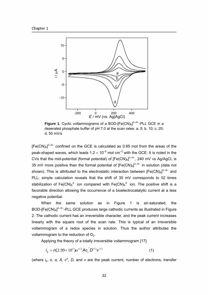
Figure 1. Cyclic voltammograms of a BOD-[Fe(CN)6]3–/4–-PLL GCE in a deaerated phosphate buffer of pH 7.0 at the scan rates: a, 5; b, 10; c, 20; d, 50 mV/s
[Fe(CN)6]3–/4– confined on the GCE is calculated as 0.85 mol from the areas of the
peak-shaped waves, which leads 1.2 × 10⁻⁸ mol cm–2 with the GCE. It is noted in the CVs that the mid-potential (formal potential) of [Fe(CN)6]3–/4–, 240 mV vs Ag/AgCl, is 35 mV more positive than the formal potential of [Fe(CN)6]3–/4– in solution (data not shown). This is attributed to the electrostatic interaction between [Fe(CN)6]3–/4– and PLL; simple calculation reveals that the shift of 35 mV corresponds to 52 times
stabilization of Fe(CN)64− ion compared with Fe(CN)6
3− ion. The positive shift is a favorable direction allowing the occurrence of a bioelectrocatalytic current at a less negative potential.
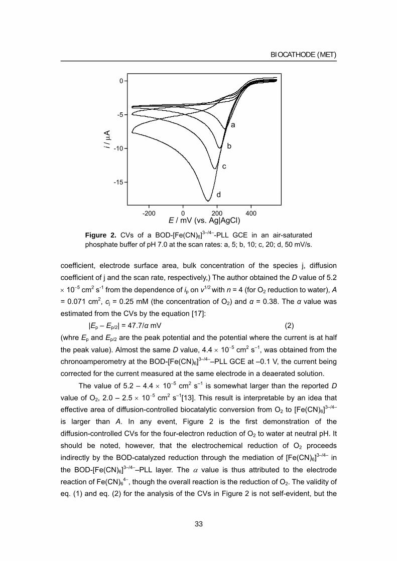
When the same solution as in Figure 1 is air-saturated, the BOD-[Fe(CN)6]3–/4–-PLL GCE produces large cathodic currents as illustrated in Figure 2. The cathodic current has an irreversible character, and the peak current increases linearly with the square root of the scan rate. This is typical of an irreversible voltammogram of a redox species in solution. Thus the author attributes the voltammogram to the reduction of O2.
Applying the theory of a totally irreversible voltammogram [17]:
212121510992 //*j
/p ).( vDAcni α×= (1)
(where ip, n, α, A, c*, D, and v are the peak current, number of electrons, transfer
32
BIOCATHODE (MET)
-15
-10
-5
0
i / μ
A
4002000-200E / mV (vs. Ag|AgCl)
a
b
c
d
Figure 2. CVs of a BOD-[Fe(CN)6]3–/4–-PLL GCE in an air-saturated phosphate buffer of pH 7.0 at the scan rates: a, 5; b, 10; c, 20; d, 50 mV/s.
coefficient, electrode surface area, bulk concentration of the species j, diffusion coefficient of j and the scan rate, respectively,) The author obtained the D value of 5.2
× 10−5 cm2 s-1 from the dependence of ip on v1/2 with n = 4 (for O2 reduction to water), A = 0.071 cm2, cj = 0.25 mM (the concentration of O2) and α = 0.38. The α value was estimated from the CVs by the equation [17]:
|Ep – Ep/2| = 47.7/α mV (2) (whre Ep and Ep/2 are the peak potential and the potential where the current is at half
the peak value). Almost the same D value, 4.4 × 10⁻⁵ cm2 s–1, was obtained from the chronoamperometry at the BOD-[Fe(CN)6]3–/4––PLL GCE at –0.1 V, the current being corrected for the current measured at the same electrode in a deaerated solution.
The value of 5.2 – 4.4 × 10⁻⁵ cm2 s–1 is somewhat larger than the reported D value of O2, 2.0 – 2.5 × 10⁻⁵ cm2 s–1[13]. This result is interpretable by an idea that effective area of diffusion-controlled biocatalytic conversion from O2 to [Fe(CN)6]3–/4– is larger than A. In any event, Figure 2 is the first demonstration of the diffusion-controlled CVs for the four-electron reduction of O2 to water at neutral pH. It should be noted, however, that the electrochemical reduction of O2 proceeds indirectly by the BOD-catalyzed reduction through the mediation of [Fe(CN)6]3–/4– in
the BOD-[Fe(CN)6]3–/4––PLL layer. The α value is thus attributed to the electrode reaction of Fe(CN)6
4−, though the overall reaction is the reduction of O2. The validity of eq. (1) and eq. (2) for the analysis of the CVs in Figure 2 is not self-evident, but the
33
Chapter 1
0.25
0.20
0.15
0.10
0.05
0.00
[O2]
/ m
M
4003002001000t / sec
Fe(CN)63−
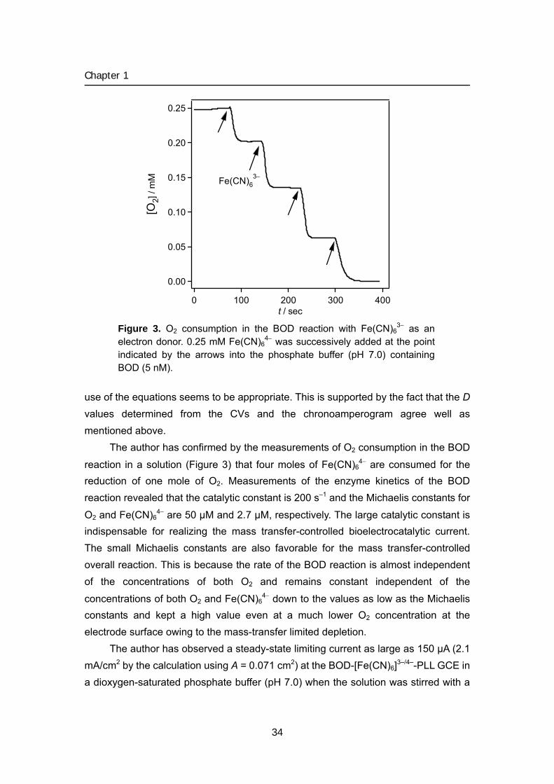
Figure 3. O2 consumption in the BOD reaction with Fe(CN)6
3− as an electron donor. 0.25 mM Fe(CN)6
4− was successively added at the point indicated by the arrows into the phosphate buffer (pH 7.0) containing BOD (5 nM).
use of the equations seems to be appropriate. This is supported by the fact that the D values determined from the CVs and the chronoamperogram agree well as mentioned above.
The author has confirmed by the measurements of O2 consumption in the BOD
reaction in a solution (Figure 3) that four moles of Fe(CN)64− are consumed for the
reduction of one mole of O2. Measurements of the enzyme kinetics of the BOD reaction revealed that the catalytic constant is 200 s–1 and the Michaelis constants for
O2 and Fe(CN)64− are 50 μM and 2.7 μM, respectively. The large catalytic constant is
indispensable for realizing the mass transfer-controlled bioelectrocatalytic current. The small Michaelis constants are also favorable for the mass transfer-controlled overall reaction. This is because the rate of the BOD reaction is almost independent of the concentrations of both O2 and remains constant independent of the
concentrations of both O2 and Fe(CN)64− down to the values as low as the Michaelis
constants and kept a high value even at a much lower O2 concentration at the electrode surface owing to the mass-transfer limited depletion.
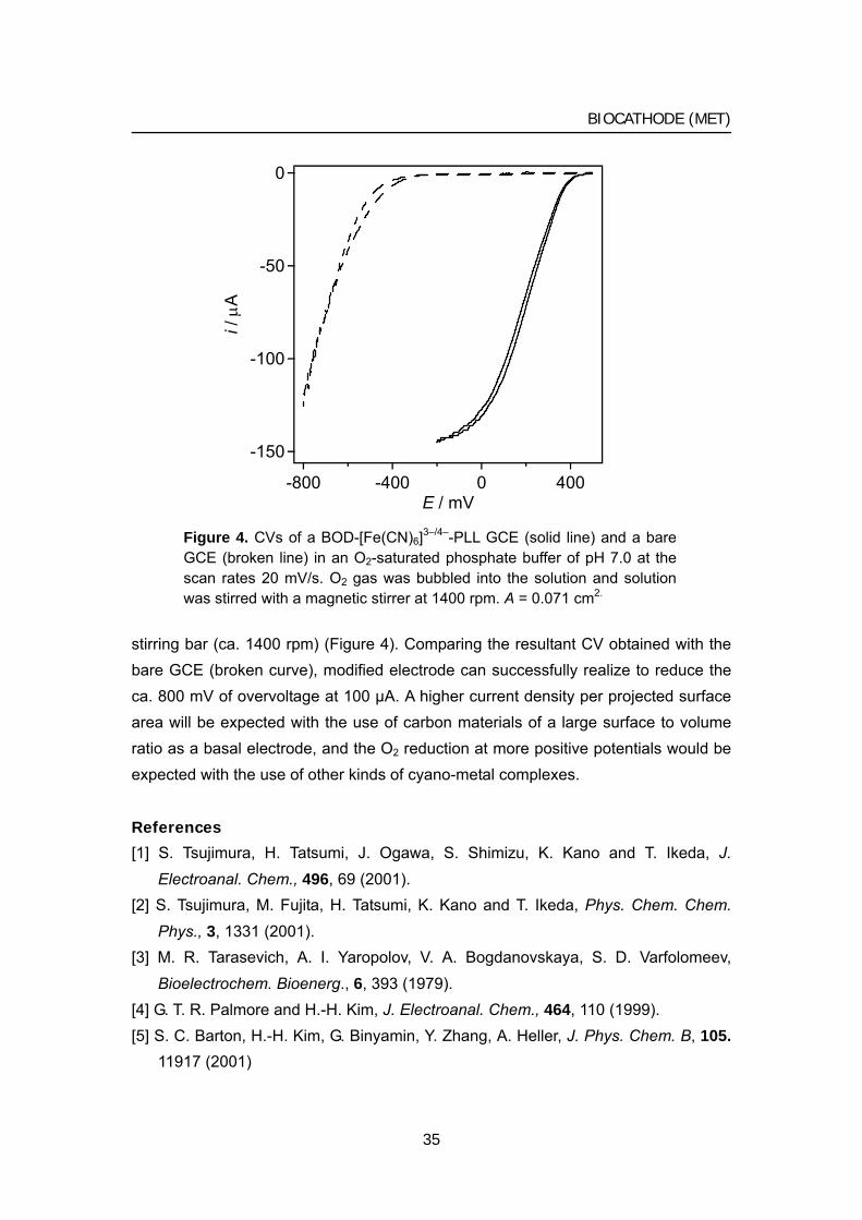
The author has observed a steady-state limiting current as large as 150 μA (2.1 mA/cm2 by the calculation using A = 0.071 cm2) at the BOD-[Fe(CN)6]3–/4–-PLL GCE in a dioxygen-saturated phosphate buffer (pH 7.0) when the solution was stirred with a
34
BIOCATHODE (MET)
-150
-100
-50
0
i / μ
A
-800 -400 0 400E / mV
Figure 4. CVs of a BOD-[Fe(CN)6]3–/4–-PLL GCE (solid line) and a bare GCE (broken line) in an O2-saturated phosphate buffer of pH 7.0 at the scan rates 20 mV/s. O2 gas was bubbled into the solution and solution was stirred with a magnetic stirrer at 1400 rpm. A = 0.071 cm2.
stirring bar (ca. 1400 rpm) (Figure 4). Comparing the resultant CV obtained with the bare GCE (broken curve), modified electrode can successfully realize to reduce the ca. 800 mV of overvoltage at 100 μA. A higher current density per projected surface area will be expected with the use of carbon materials of a large surface to volume ratio as a basal electrode, and the O2 reduction at more positive potentials would be expected with the use of other kinds of cyano-metal complexes.
References
[1] S. Tsujimura, H. Tatsumi, J. Ogawa, S. Shimizu, K. Kano and T. Ikeda, J.
Electroanal. Chem., 496, 69 (2001). [2] S. Tsujimura, M. Fujita, H. Tatsumi, K. Kano and T. Ikeda, Phys. Chem. Chem.
Phys., 3, 1331 (2001). [3] M. R. Tarasevich, A. I. Yaropolov, V. A. Bogdanovskaya, S. D. Varfolomeev,
Bioelectrochem. Bioenerg., 6, 393 (1979). [4] G. T. R. Palmore and H.-H. Kim, J. Electroanal. Chem., 464, 110 (1999). [5] S. C. Barton, H.-H. Kim, G. Binyamin, Y. Zhang, A. Heller, J. Phys. Chem. B, 105.
11917 (2001)
35
Chapter 1
[6] S. C. Barton, H.-H. Kim, G. Binyamin, Y. Zhang, A. Heller, J. Am. Chem. Soc., 123, 5802 (2001).
[7] N. Tanaka, S. Murao, Agric. Biol. Chem., 46, 2499 (1982). [8] Y. Gotoh, Y. Kondo, H. Kaji, A. Takeda, T. Samejima, J. Biochem., 106, 621 (1989). [9] Shimizu, J-H. Kwon, T. Sasaki, T. Satoh, N. Sakurai, T. Sakurai, S. Yamaguchi, T.,
Samejima, Biochemistry, 38, 3034 (1999). [10] Shimizu, T. Sasaki, J-H. Kwon, A. Odaka, T. Satoh, N. Sakurai, T. Sakurai, S.
Yamaguchi, T. Samejima, J. Biochem.,125, 662 (1999). [11] S. Murao, N. Tanaka, Agric. Biol. Chem., 46, 2031 (1982). [12] F. Xu, W. Shin, S. H. Brown, J. A. Wahleithner, U. M. Sundaram, E. I. Solomon,
Biochim. Biophys. Acta, 1292, 303 (1996). [13] N. Mano, H.-H Kim, Y. Zhang and A. Heller, J. Am. Chem. Soc., 124, 6480
(2002). [14] N. Mano, H.-H Kim and A. Heller, J. Phys. Chem. B., 106, 8842 (2002). [15] N. Oyama and F. C. Anson, J. Electroanal. Chem., 127, 247 (1980). [16] T. Ikeda, T. Shiraishi and M. Senda, Agric. Biol. Chem., 52, 3187 (1988). [17] A. J. Bard and L. R. Faukner “Electrochemical Methods, Fundamentals and
Applications” Second ed. Wiley, New York, 2001, p. 236. [18] M. Tsushima, K. Tokuda, T. Ohsaka, Anal. Chem., 66, 4551 (1994).
36
BIOCATHODE (MET)
3 Mediated bioelectrocatalytic O2 reduction to water at highly positive electrode potentials near neutral pH
Combinations of bilirubin oxidase and metal complexes: [W(CN)8]3−/4−, [Os(CN)6]3−/4−
and [Mo(CN)8]3−/4− (the formal potentials, E°’(M), being 0.320, 0.448, and 0.584 V vs.
Ag|AgCl, respectively, at pH 7.0), allowed bioelectrocatalytic reduction of O2 to water
at their formal potentials near neutral pH. The O2 reduction current appeared even at
the standard potential of the O2/H2O redox couple, E°’(O2/H2O), when [Mo(CN)8]3−/4−
was used at pH 7.4, though the magnitude was small. The magnitude of the
bioelectrocatalytic current systematically decreased with the decrease in the potential
difference between E°’(O2/H2O) and E°’(M). A limiting current as large as 17 mA per
square centimeter of a projected electrode surface area was obtained at 0.25 V (−0.37
V vs. E°’(O2/H2O)) for the O2 reduction at pH 7.0 with a carbon felt electrode modified
with electrostatically entrapped bilirubin oxidase and [W(CN)8]3−/4− at the electrode
rotation rate of 4000 rpm.
Introduction
Recently the author has demonstrated that bilirubin oxidase (BOD), a multi-copper enzyme catalyzing oxidation of bilirubin to biliverdin with O2, has an excellent property of producing a mediated bioelectrocatalytic current for the reduction of O2 to water near neutral pH [1]. This is contrasted to the hitherto reported mediated bioelectrocatalytic O2 reductions using laccases; the laccase-based bioelectrocatalytic currents appear in an appreciable magnitude only in acidic solutions (less than pH 5.0) owing to the very low activity of laccases above pH 5.0 [2-5]; therefore a biofuel cell utilizing laccase for the dioxygen reduction reaction should operate in acidic condition [6-9].
BOD has accordingly been utilized in the constructions of a dioxygen biocathode operating near neutral pH of a H2/O2 biofuel cell [10], a photosynthetic bioelectrochemical cell [11], and glucose/O2 biofuel cells [12, 13]. The potential at which the bioelectrocatalytic current starts to appear exclusively depends on the
formal potential, E°’(M), of the mediator compound employed; that is, 2,2’-azinobis(3-ethylbenzothiazolin-6-sulfonate), ABTS, (E°’(M) = 0.505 V vs. Ag|AgCl) [1, 10, 11], Os(2,2’-bipyridine)2Cl complexed with a poly(4-vinylpyridine)
(E°’(M) = 0.350 V vs. Ag|AgCl) [12], and Os(4,4’-dichloro-2,2’-bipyridine)2Cl complexed with a 1:7 polyacrylamide-poly(N-vinylimidazole) copolymer (E°’(M) =
37
Chapter 1
0.350 V vs. Ag|AgCl) [13-15]. In biofuel cell applications, a large current density (that is, a rapid mediated bioelectrocatalytic reaction) is required at a potential as positive
as possible, ideally at the O2/H2O standard potential, E°’(O2/H2O) (the standard potential at pH = 0 (at unit activity of H+), E°(O2/H2O), is 1.229 V vs. NHE [16]). Considering the idea of a linear free energy relationship, however, the author may
anticipate that the rate of the bioelectrocatalytic reaction becomes smaller, as E°’(M) becomes closer to E°’(O2/H2O) (and also to the redox potential of the enzyme, E°’(Enz)). The present communication demonstrates that the effect of the potential differences on the rate of the catalytic reaction is clearly observed in the bioelectrocatalytic systems of BOD with metal complexes functioning as very effective
mediators: [W(CN)8]3−/4−, [Os(CN)6]3−/4− and [Mo(CN)8]3−/4−.
Experimental
BOD (EC 1.3.3.5, 3.31 U mg−1) from Myrothecium verrucaria was a gift from Amano Pharmaceutical Co Japan. The concentration of BOD in a stock solution was
determined by the absorbance measurement at 600 nm with ε = 4800 [17]. Metal complexes [W(CN)8]4–, [Os(CN)6]4− and [Mo(CN)8]4− were synthesized as potassium salts according to the methods in the literatures [18-20]. Cyclic voltammetry was performed using a BAS 50W voltammetric analyzer in a three electrode system with a glassy carbon electrode (GCE) (3 mm diameter, BAS), Ag|AgCl(sat. KCl) and a Pt disk as the working, reference and counter electrodes, respectively. Britton and Robinson buffer, that was made by mixing 0.1 M boric acid, 0.1 M acetic acid, and 0.1 M phosphoric acid with 1M NaOH to the desired pH, was used to adjust the pH of the
test solutions and the voltammograms of the solutions were recorded at 25 °C. In this communication, potentials are referred to Ag|AgCl(sat. KCl) unless otherwise stated.
An electrode with immobilized BOD and [W(CN)8]4− was prepared by the following procedure. A carbon felt sheet (1 mm thickness, Toray B0050; a gift from Toray Co.) was cut into 3 mm diameter disks, and 3 μL BOD (210 μM), 10 μL
[W(CN)8]4− (10 mM), and 5 μL 1.3% (w/v) poly-L-lysine (PLL) (PLL hydrochloride, cut off molecular weight 8000, purchased from Peptide Institute INC. Osaka, lot No. 350408) were syringed successively onto the disk. After the solvent of the solution on the disk was allowed to evaporate in a dry box overnight, the disk with immobilized
BOD and [W(CN)8]4− was mounted on the surface of a glassy carbon electrode and fixed with a piece of nylon net covering the electrode. Rotated disk voltammograms
were recorded with the BOD- and [W(CN)8]4−- modified electrode in a phosphate buffer at pH 7.0 using a BAS RDE-1.
38
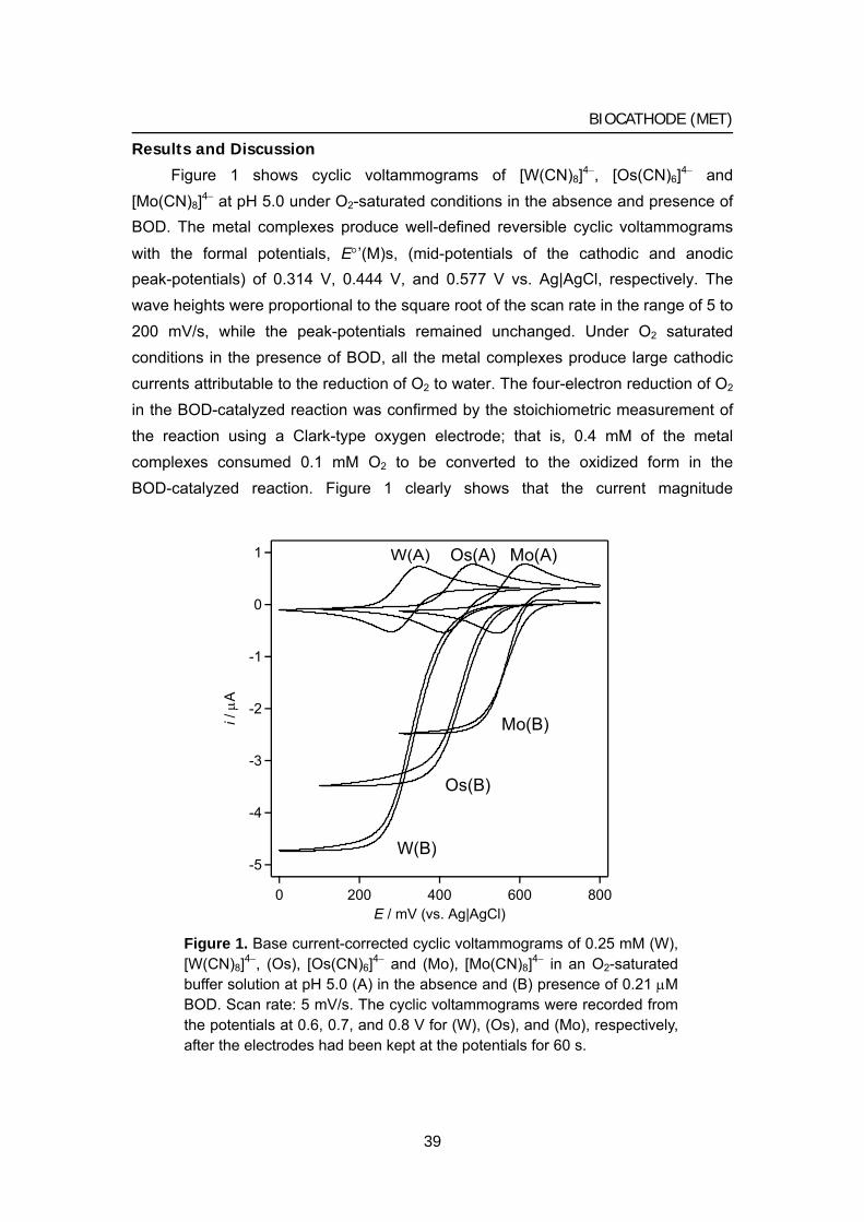
BIOCATHODE (MET)
Results and Discussion
Figure 1 shows cyclic voltammograms of [W(CN)8]4−, [Os(CN)6]4− and [Mo(CN)8]4− at pH 5.0 under O2-saturated conditions in the absence and presence of BOD. The metal complexes produce well-defined reversible cyclic voltammograms
with the formal potentials, E°’(M)s, (mid-potentials of the cathodic and anodic peak-potentials) of 0.314 V, 0.444 V, and 0.577 V vs. Ag|AgCl, respectively. The wave heights were proportional to the square root of the scan rate in the range of 5 to 200 mV/s, while the peak-potentials remained unchanged. Under O2 saturated conditions in the presence of BOD, all the metal complexes produce large cathodic currents attributable to the reduction of O2 to water. The four-electron reduction of O2 in the BOD-catalyzed reaction was confirmed by the stoichiometric measurement of the reaction using a Clark-type oxygen electrode; that is, 0.4 mM of the metal complexes consumed 0.1 mM O2 to be converted to the oxidized form in the BOD-catalyzed reaction. Figure 1 clearly shows that the current magnitude
-5
-4
-3
-2
-1
0
1
i / μ
A
8006004002000E / mV (vs. Ag|AgCl)
W(A) Os(A) Mo(A)
W(B)
Os(B)
Mo(B)
Figure 1. Base current-corrected cyclic voltammograms of 0.25 mM (W), [W(CN)8]4−, (Os), [Os(CN)6]4− and (Mo), [Mo(CN)8]4− in an O2-saturated buffer solution at pH 5.0 (A) in the absence and (B) presence of 0.21 μM BOD. Scan rate: 5 mV/s. The cyclic voltammograms were recorded from the potentials at 0.6, 0.7, and 0.8 V for (W), (Os), and (Mo), respectively, after the electrodes had been kept at the potentials for 60 s.
39
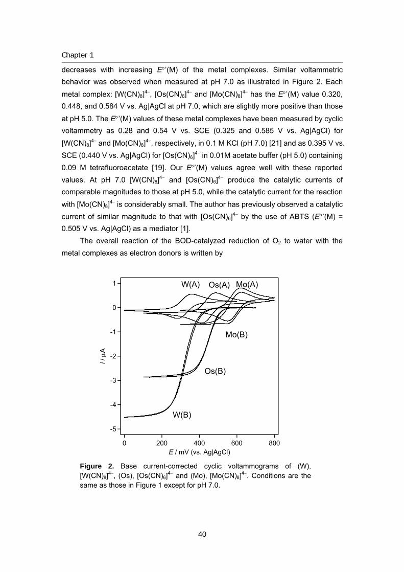
Chapter 1
decreases with increasing E°’(M) of the metal complexes. Similar voltammetric behavior was observed when measured at pH 7.0 as illustrated in Figure 2. Each
metal complex: [W(CN)8]4−, [Os(CN)6]4− and [Mo(CN)8]4− has the E°’(M) value 0.320, 0.448, and 0.584 V vs. Ag|AgCl at pH 7.0, which are slightly more positive than those
at pH 5.0. The E°’(M) values of these metal complexes have been measured by cyclic voltammetry as 0.28 and 0.54 V vs. SCE (0.325 and 0.585 V vs. Ag|AgCl) for
[W(CN)8]4− and [Mo(CN)8]4−, respectively, in 0.1 M KCl (pH 7.0) [21] and as 0.395 V vs. SCE (0.440 V vs. Ag|AgCl) for [Os(CN)6]4− in 0.01M acetate buffer (pH 5.0) containing 0.09 M tetrafluoroacetate [19]. Our E°’(M) values agree well with these reported values. At pH 7.0 [W(CN)8]4− and [Os(CN)6]4− produce the catalytic currents of comparable magnitudes to those at pH 5.0, while the catalytic current for the reaction
with [Mo(CN)8]4− is considerably small. The author has previously observed a catalytic current of similar magnitude to that with [Os(CN)6]4− by the use of ABTS (E°’(M) = 0.505 V vs. Ag|AgCl) as a mediator [1].
The overall reaction of the BOD-catalyzed reduction of O2 to water with the metal complexes as electron donors is written by
-5
-4
-3
-2
-1
0
1
i / μ
A
8006004002000E / mV (vs. Ag|AgCl)
W(A) Os(A) Mo(A)
W(B)
Os(B)
Mo(B)
Figure 2. Base current-corrected cyclic voltammograms of (W), [W(CN)8]4−, (Os), [Os(CN)6]4− and (Mo), [Mo(CN)8]4−. Conditions are the same as those in Figure 1 except for pH 7.0.
40
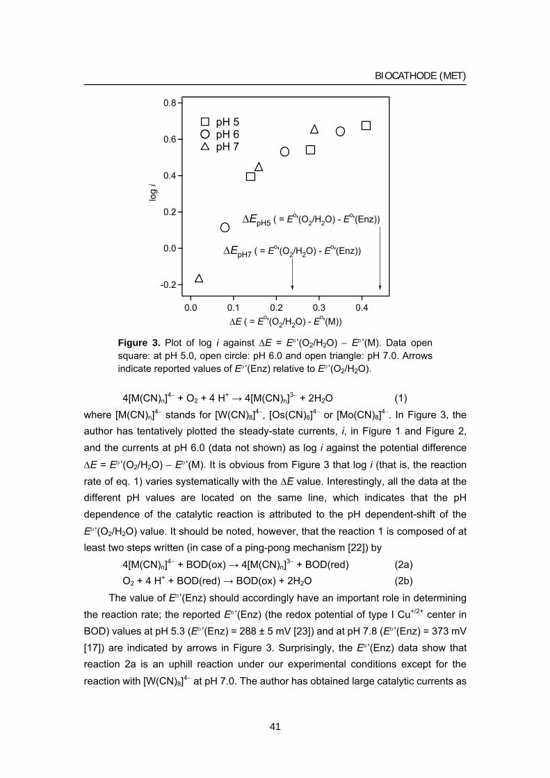
BIOCATHODE (MET)
0.8
0.6
0.4
0.2
0.0
-0.2
log
i
0.40.30.20.10.0ΔE ( = Eo'(O2/H2O) - Eo'(M))
ΔEpH7 ( = Eo'(O2/H2O) - Eo'(Enz))
ΔEpH5 ( = Eo'(O2/H2O) - Eo'(Enz))
pH 5 pH 6 pH 7
Figure 3. Plot of log i against ΔE = E°’(O2/H2O) − E°’(M). Data open square: at pH 5.0, open circle: pH 6.0 and open triangle: pH 7.0. Arrows indicate reported values of E°’(Enz) relative to E°’(O2/H2O). 4[M(CN)n]4− + O2 + 4 H+ → 4[M(CN)n]3− + 2H2O (1)
where [M(CN)n]4− stands for [W(CN)8]4−, [Os(CN)6]4− or [Mo(CN)8]4−. In Figure 3, the author has tentatively plotted the steady-state currents, i, in Figure 1 and Figure 2, and the currents at pH 6.0 (data not shown) as log i against the potential difference
ΔE = E°’(O2/H2O) − E°’(M). It is obvious from Figure 3 that log i (that is, the reaction rate of eq. 1) varies systematically with the ΔE value. Interestingly, all the data at the different pH values are located on the same line, which indicates that the pH dependence of the catalytic reaction is attributed to the pH dependent-shift of the
E°’(O2/H2O) value. It should be noted, however, that the reaction 1 is composed of at least two steps written (in case of a ping-pong mechanism [22]) by
4[M(CN)n]4− + BOD(ox) → 4[M(CN)n]3− + BOD(red) (2a) O2 + 4 H+ + BOD(red) → BOD(ox) + 2H2O (2b)
The value of E°’(Enz) should accordingly have an important role in determining the reaction rate; the reported E°’(Enz) (the redox potential of type I Cu+/2+ center in BOD) values at pH 5.3 (E°’(Enz) = 288 ± 5 mV [23]) and at pH 7.8 (E°’(Enz) = 373 mV [17]) are indicated by arrows in Figure 3. Surprisingly, the E°’(Enz) data show that reaction 2a is an uphill reaction under our experimental conditions except for the
reaction with [W(CN)8]4− at pH 7.0. The author has obtained large catalytic currents as
41
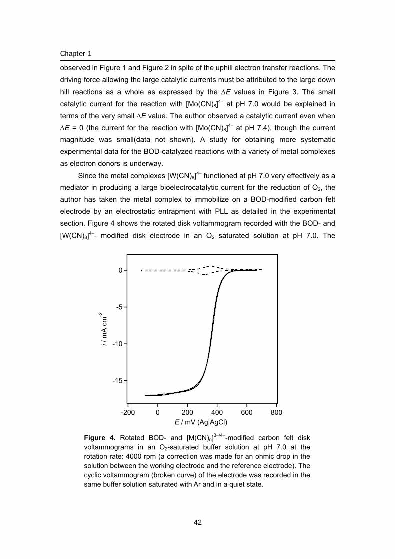
Chapter 1
observed in Figure 1 and Figure 2 in spite of the uphill electron transfer reactions. The driving force allowing the large catalytic currents must be attributed to the large down
hill reactions as a whole as expressed by the ΔE values in Figure 3. The small catalytic current for the reaction with [Mo(CN)8]4− at pH 7.0 would be explained in terms of the very small ΔE value. The author observed a catalytic current even when ΔE = 0 (the current for the reaction with [Mo(CN)8]4− at pH 7.4), though the current magnitude was small(data not shown). A study for obtaining more systematic experimental data for the BOD-catalyzed reactions with a variety of metal complexes as electron donors is underway.
Since the metal complexes [W(CN)8]4− functioned at pH 7.0 very effectively as a mediator in producing a large bioelectrocatalytic current for the reduction of O2, the author has taken the metal complex to immobilize on a BOD-modified carbon felt electrode by an electrostatic entrapment with PLL as detailed in the experimental section. Figure 4 shows the rotated disk voltammogram recorded with the BOD- and
[W(CN)8]4−- modified disk electrode in an O2 saturated solution at pH 7.0. The
-15
-10
-5
0
i / m
A c
m-2
8006004002000-200E / mV (Ag|AgCl)
Figure 4. Rotated BOD- and [M(CN)n]3−/4−-modified carbon felt disk voltammograms in an O2-saturated buffer solution at pH 7.0 at the rotation rate: 4000 rpm (a correction was made for an ohmic drop in the solution between the working electrode and the reference electrode). The cyclic voltammogram (broken curve) of the electrode was recorded in the same buffer solution saturated with Ar and in a quiet state.
42
BIOCATHODE (MET)
voltammogram attained a limiting current at 0.25 V. The current magnitude was very large as compared with the small surface wave (broken curve in Figure 4) due to the redox reaction of the metal complex confined in the modified BOD layer on the carbon-felt disk. Calculation using the projected surface area of the electrode (3 mm diameter of the carbon felt disk) yields the current density 17 mA/cm2 at the rotation rate of 4000 rpm. Tentative calculation of the effective electrode surface area from the limiting current by the Levich equation with the diffusion coefficient of O2, D = 2.07
×10−5 cm2 s−1 [24] and with the saturated concentration of O2, cO2 = 1.28 mM [24] lead to 0.12 cm2 for the BOD- and [W(CN)8]4− - modified disk electrodes. The larger surface area as compared with the projected surface area (0.07 cm2) is indicative of the convective penetration of the solution within the felt matrix to some extent. The convective penetration suggests that the felt electrode is capable of producing higher current densities per projected surface area at higher rates of the convective mass transfer and is promising for the use as a cathode of a high current density in biofuel cells. References [1] S. Tsujimura, H. Tatsumi, J. Ogawa, S. Shimizu, K. Kano, T. Ikeda, J. Electroanal.
Chem., 496, 69 (2001). [2] W. Jin., U. Wollenberger, F. F. Bier, A. Makower, F. W. Scheller, Bioelectrochem.
Bioenerg., 39, 221 (1996). [3] F. Trudeau, F. Daigle and D. Leech, Anal. Chem., 69, 882 (1997). [4] P. Bourbonnas, D. Leech and M. G. Paice, Biochim. Biophys. Acta, 1379, 381
(1998). [5] G. T. R. Palmore and H. -H. Kim, J. Electroanal. Chem., 464, 110 (1999). [6] T. Chen, S. C. Barton, G. Binyamin, Z. Gao, Y. Zhang, H.-H. Kim and A. Heller, J.
Am. Chem. Soc., 123, 8630 (2001). [7] S. C. Barton, H.-H. Kim, G. Binyamin, Y. Zhang and A. Heller, J. Am. Chem. Soc.,
123, 5802 (2001). [8] S. C. Barton, H.-H. Kim, G. Binyamin, Y. Zhang and A. Heller, J. Phys. Chem. B,
105, 11917 (2001). [9] S. C. Barton, M. Pickard, R. V-Duhalt and A. Heller, Biosensors and Bioelectronics,
17, 1071 (2002). [10] S. Tsujimura, M. Fujita, H. Tatsumi, K. Kano and T.Ikeda, Phys. Chem. Chem.
Phys., 3, 1331 (2001).
43
Chapter 1
44
[11] S. Tsujimura, A. Wadano, K. Kano, and T. Ikeda, Enz. Microbial Tech., 29, 225 (2001).
[12] S. Tsujimura, K. Kano, T. Ikeda, Electrochemistry, 70, 940 (2002). [13] N. Mano, H.-H. Kim, Y. Zhang and A. Heller, J. Am. Chem. Soc., 124, 6480
(2002) [14] N. Mano, H.-H. Kim and A. Heller, J. Phys. Chem. B, 106, 8842 (2002). [15] N. Mano, F. Mao and A. Heller, J. Am. Chem. Soc., 124, 12962 (2002). [16] A. J. Bard and L. R. Faulkner, Electrochemical Methods, Wiley, New York, (980). [17] A. Shimizu, T. Sasaki, J-H. Kwon, A. Odaka, T. Satoh, N. Sakurai, T. Sakurai, S.
Yamaguchi, T. Samejima, J. Biochem., 125, 662(1999) [18] J. G. Leipoldt, L. D. C. Bok, and P. J. Cilliers, Z. Anorg. Allg. Chem., 407, 350
(1974). [19] J. C. Curtis and T. J. Meyer, Inorg. Chem., 21 (1982) 1562 [20] J. G. Leipoldt, L. D. C. Bok, and P. J. Cillers, Z. Anorg. Allg. Chem., 409, 343
(1974). [21] I. Taniguchi, S. Miyamoto, S. Tomimura and F. M. Hawkridge, J. Electroanal.
Chem., 240, 333 (1988). [22] Sigel, Enzyme Kinetics, Wiley, New York, Ch 9, (1993). [23] F. Xu, W. Shin, S. H. Brown, J. A. Wahleithner, U. M. Sundaram, E. I. Solomon,
Biochim. Biophys. Acta, 1292, 303 (1996). [24] M. Tsushima, K. Tokuda, and T. Ohsaka, Anal. Chem., 66, 4551 (1994).
2
Biocathode (2) Direct electron transfer-type bioelectrochemical reduction of O2 using bilirubin oxidase
Kinetic study of direct bioelectrocatalysis of dioxygen reduction with bilirubin oxidase at carbon
electrodes
1
Direct electron transfer-type bioelectrocatalysis of four-electron reduction of dioxygen
was successfully realized with bilirubin oxidase (BOD, EC 1.3.3.5, from Myrothecium
verrucaria) at carbon electrode surfaces with high crystal graphite edge density. It was
found that adsorbed BOD functions as a biocatalyst. The current-potential curves were
interpreted by considering the enzyme catalytic constant, surface electron transfer
kinetics, surface concentration of BOD, and the formal potential of BOD. The analysis
suggested that the standard surface electron transfer rate constant and surface
coverage of “active” enzyme depend strongly on functional groups and/or
nano-structure of carbon electrode surface.
Introduction
Direct electron transfer (DET) between enzymes and electrodes has been attracting considerable attention for construction of the 3rd generation biosensors and biofuel cells. DET-based catalytic phenomena have been reported for limited species of enzymes [1-6]. All these enzymes have more than one redox center and it has been proposed that one of the redox centers can work as a build-in mediator (or a specific site) for electron transfer (ET) between enzymes and electrodes [5, 6].
Bilirubin oxidase (BOD, EC 1.3.3.5, from Myrothecium verrucaria) is a family of multi-copper enzyme and contains type 1, type 2, and type 3 coppers (in the ratio of
45
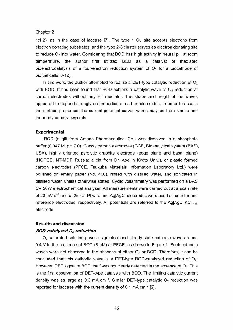
Chapter 2
1:1:2), as in the case of laccase [7]. The type 1 Cu site accepts electrons from electron donating substrates, and the type 2-3 cluster serves as electron donating site to reduce O2 into water. Considering that BOD has high activity in neural pH at room temperature, the author first utilized BOD as a catalyst of mediated bioelectrocatalysis of a four-electron reduction system of O2 for a biocathode of biofuel cells [8-12].
In this work, the author attempted to realize a DET-type catalytic reduction of O2 with BOD. It has been found that BOD exhibits a catalytic wave of O2 reduction at carbon electrodes without any ET mediator. The shape and height of the waves appeared to depend strongly on properties of carbon electrodes. In order to assess the surface properties, the current-potential curves were analyzed from kinetic and thermodynamic viewpoints.
Experimental
BOD (a gift from Amano Pharmaceutical Co.) was dissolved in a phosphate buffer (0.047 M, pH 7.0). Glassy carbon electrodes (GCE, Bioanalytical system (BAS), USA), highly oriented pyrolytic graphite electrode (edge plane and basal plane) (HOPGE, NT-MDT, Russia; a gift from Dr. Abe in Kyoto Univ.), or plastic formed carbon electrodes (PFCE, Tsukuba Materials Information Laboratory Ltd.) were polished on emery paper (No. 400), rinsed with distilled water, and sonicated in distilled water, unless otherwise stated. Cyclic voltammetry was performed on a BAS CV 50W electrochemical analyzer. All measurements were carried out at a scan rate
of 20 mV s–1 and at 25 °C. Pt wire and Ag|AgCl electrodes were used as counter and reference electrodes, respectively. All potentials are referred to the Ag|AgCl|KCl sat.
electrode.
Results and discussion
BOD-catalyzed O2 reduction O2-saturated solution gave a sigmoidal and steady-state cathodic wave around
0.4 V in the presence of BOD (8 μM) at PFCE, as shown in Figure 1. Such cathodic waves were not observed in the absence of either O2 or BOD. Therefore, it can be concluded that this cathodic wave is a DET-type BOD-catalyzed reduction of O2. However, DET signal of BOD itself was not clearly detected in the absence of O2. This is the first observation of DET-type catalysis with BOD. The limiting catalytic current density was as large as 0.3 mA cm–2. Similar DET-type catalytic O2 reduction was reported for laccase with the current density of 0.1 mA cm–2 [2].
46
BIOCATHODE (DET)
When the immersed electrode was took out from the BOD solution and rinsed well with distilled water, the voltammogram at the electrode remained almost unchanged in an O2-saturated buffer in the absence of BOD. The result suggests that BOD absorbs on the electrode surface from the solution and that the adsorbed BOD functions as a catalyst.
k°
O2
2H2O
Type 1 copper
Type 2-3 copper cluster
ELECTRODE
kc
BOD
Scheme 1. Schematic representation of DET-type bioelectrocatalytic reduction of O2 with BOD adsorbed on electrodes.
0
0
0
0
0
0
0
6004002000E / mV (Ag|AgCl)
50 μA cm-2
HOPGE (edge plane)
PFCE
6004002000E / mV (Ag|AgCl)
2 μA cm-2
HOPGE (basal plane)
GCE
Figure 1. Background current-corrected steady-state liner sweep voltammograms recorded with BOD-adsorbed electrodes prepared with HOPGE (edge plane), PFCE, HOPGE (basal plane), and GCE at pH 7.0. The open square and circles represent the regression curves based on Eqs. (1)–(3) with the parameter given in the text and Table 1.
47
Chapter 2
Interestingly, the BOD-adsorbed electrode lost the catalytic activity completely, when the electrode was dried out in a desiccator for 1 h at room temperature. This may be due to denaturation of BOD by losing water molecule surrounding BOD.
The catalytic wave started to increase around 0.5 V, which is very close to the formal potential of the type I Cu site of BOD [13]. This suggests that electrons are transferred from electrode to the type 1 Cu site of adsorbed BOD and then to the type 2-3 Cu sites, where O2 is reduced to water, as illustrated in Scheme 1.
Significance of electrode material and surface in DET-type biocatalysis Figure 1 shows the background current-corrected steady-state voltammograms of
the catalytic O2 reduction in the presence of BOD at various carbon electrodes. Edge plane-HOPGE was found to be a good material for the DET-type catalysis of BOD as in the case of PFCE. In contrast, only low density of the catalytic current was observed on GCE or basal plane-HOPGE polished with the emery paper. Such catalytic current was not observed at all, when GCE was polished to a mirror-like finish with alumina slurry (0.05 μm diameter) or when basal plane-HOPGE was used just after cutting without polishing.
It is well known that crystal edge plane of graphite enables fast homogeneous ET of various hydrophilic compounds and that graphite basal plane with extremely smooth surface is not suitable for fast ET. PFCE contains high density of graphite edge plane oriented toward the axial direction, and has some structural similarity with edge plane-HOPGE [14-16]. Polish treatment of GCE and basal plane-HOPGE with the emery paper may produce similar crystal edge plane in part. Such crystal edge plane of graphite seems to play an important role in DET of BOD. Au or Pt electrodes (polished with alumina powder) did not show any BOD-catalyzed reduction of O2. Modification of Au electrodes with 4,4’-bipyrydine disulfide did not improve DET-type catalysis of BOD. All these results suggest significance of carbon material and its surface property for DET of BOD.
Kinetic analysis of DET-type catalysis of BOD One of the important approaches to understand the DET-type BOD catalysis is
quantitative interpretation of the current-potential curves. Considering the DET-model given in Scheme 1, the current density (i) can be expressed by:
fbfc
tc
// kkkknFk
i++Γ
=1
(1)
48
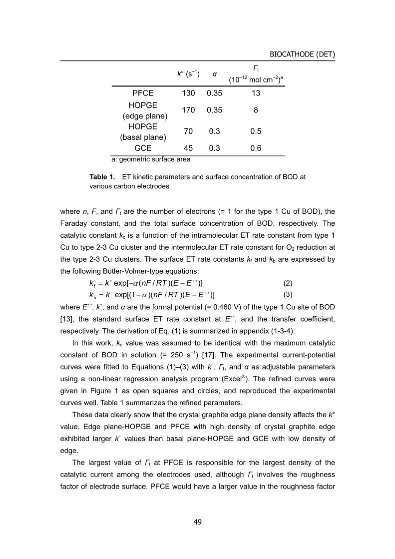
BIOCATHODE (DET)
k° (s–1) α Γt
(10–12 mol cm–2)a
PFCE 130 0.35 13 HOPGE
(edge plane) 170 0.35 8
HOPGE (basal plane)
70 0.3 0.5
GCE 45 0.3 0.6 a: geometric surface area
Table 1. ET kinetic parameters and surface concentration of BOD at various carbon electrodes
where n, F, and Γt are the number of electrons (= 1 for the type 1 Cu of BOD), the Faraday constant, and the total surface concentration of BOD, respectively. The catalytic constant kc is a function of the intramolecular ET rate constant from type 1 Cu to type 2-3 Cu cluster and the intermolecular ET rate constant for O2 reduction at the type 2-3 Cu clusters. The surface ET rate constants kf and kb are expressed by the following Butler-Volmer-type equations:
)]')(/(exp[foo EERTnFkk −−= α (2)
)]')(/)(exp[(boo EERTnFkk −−= α1 (3)
where E˚´, k˚, and α are the formal potential (= 0.460 V) of the type 1 Cu site of BOD [13], the standard surface ET rate constant at E˚´, and the transfer coefficient, respectively. The derivation of Eq. (1) is summarized in appendix (1-3-4).
In this work, kc value was assumed to be identical with the maximum catalytic constant of BOD in solution (= 250 s–1) [17]. The experimental current-potential curves were fitted to Equations (1)–(3) with k˚, Γt, and α as adjustable parameters using a non-linear regression analysis program (Excel®). The refined curves were given in Figure 1 as open squares and circles, and reproduced the experimental curves well. Table 1 summarizes the refined parameters.
These data clearly show that the crystal graphite edge plane density affects the k° value. Edge plane-HOPGE and PFCE with high density of crystal graphite edge exhibited larger k˚ values than basal plane-HOPGE and GCE with low density of edge.
The largest value of Γt at PFCE is responsible for the largest density of the catalytic current among the electrodes used, although Γt involves the roughness factor of electrode surface. PFCE would have a larger value in the roughness factor
49
Chapter 2
than the other electrodes used [14], which would be responsible in part for the large value of Γt. In contrast, basal-plane-HOPGE and GCE exhibited small Γt, in spite of that the surface roughness factors of these electrodes would be larger than unity because of polishing treatment with the emery paper.
Judging from k˚ values at PFCE and edge-plane HOPGE, non-catalytic surface wave of adsorbed BOD, if observed, would be reversible at least at 20 mV s–1 and the
peak current density is expected to be about 0.2 μA cm–2 at Γt ≅ 1 × 10–11 mol cm–2. The expected peak current density is much smaller than the base current density and the catalytic current density. This might be the reason why DET signal of adsorbed BOD could not be identified clearly in the absence of O2. Here, it is noteworthy that the present analysis allows rough evaluation of DET kinetic parameters (and Γt of “active” enzymes adsorbed on electrode surfaces) from current-potential curves of catalytic waves, although development of another method is demanded for evaluation of total Γt of “active and denatured” enzymes adsorbed on electrode surfaces.
The present results suggest that functional groups and/or nano-structural properties of carbon electrode surface would be important factor(s) governing the surface ET kinetics and the adsorptive property of BOD with retaining enzymatic function.
Appendix: Expression of steady-state voltammograms in DET-type bioelectrocatalysis current-potential curve (Eq. (1))
The steady-state current density (i) obtained in the reaction represented as scheme 1 is given by:
RbOf ΓkΓknFA
i−= (4)
RcΓknFA
i= (5)
where ΓO is the surface concentration of oxidized form of enzyme and and ΓR is the one of reduced enzyme. The maximum current can be expressed by:
tcmax Γk
nFAi
= (6)
with
ROt ΓΓΓ += (7)
From Eq. (4), (5), and (7), following equation is obtained:
RbRtfRc )( ΓkΓΓkΓk −−=
Rbftf )( ΓkkΓk +−= (8)
50
BIOCATHODE (DET)
Then ΓR is expressed by
)( bfc
tfR kkk
ΓkΓ++
= (9)
Eqs. (5) can be rewritten with Eq. (9) to give Eq. (1).
)( bfc
tcf
kkkΓkk
nFAi
++=
f
b
f
c
tc
kk
kkΓk
++=
1 (1)
References
[1] T. Ikeda, Frontiers in Biosensorics I (Eds. F. W. Scheller, F. Schubert, and J. Fedrowitz), Birkhäuser Verlag, Berlin, p. 243 (1997).
[2] A. L. Ghindilis, P. Atanasov, and E. Wilkins, Electroanalysis, 9, 661 (1997). [3] A. I. Yaropolov, A. N. Kharybin, J. Emnéus, G. Marko-Varga, and L. Gorton,
Bioelectrochem. Bioenerg., 40. 49 (1996). [4] T. Larsson, A. Lindgren, T. Ruzgas, S-E, Lindquist, and L. Gorton, J. Electroanal.
Chem., 482, 1 (2000). [5] T. Ikeda, D. Kobayashi, F. Matsushita, T. Sagara, and K. Niki, J. Electroanal.
Chem., 361, 221 (1993). [6] L. J. C. Jeuken, A. K. Jones, S. K. Chapman, G. Cecchini, and F.A. Armstrong, J.
Am. Chem. Soc., 124, 5702 (2002) [7] N. Tanaka, S. Murao, Agric. Biol. Chem. 46 2499 (1982). [8] S. Tsujimura, H. Tatsumi, J. Ogawa, S. Shimizu, K. Kano and T. Ikeda, J.
Electroanal. Chem., 496, 69 (2001). [9] S. Tsujimura, M. Fujita, H. Tatsumi, K. Kano and T. Ikeda, Phys. Chem. Chem.
Phys., 3, 1331 (2001). [10] S. Tsujimura, A. Wadano, K. Kano and T. Ikeda, Enyme Microb. Tech., 29, 225
(2001) [11] S. Tsujimura, K. Kano and T. Ikeda, Electrochemistry, 70, 940 (2002). [12] S. Tsujimura, M. Kawaharada, T. Nakagawa, K. Kano, and T. Ikeda, Electrochem.
Comm., 5, 138 (2003). [13] A. Kuriyama, M. Arasaki, N. Fujieda, S. Tsujimura, K. Kano, and T. Ikeda, Rev.
Polarogr., 49, 192 (2003) (in Japanese).
51

Chapter 2
[14] T. Kawakubo, Y. Suda, H. Kaneko, A. Negishi, and M. Yamada, Tanso, 152, 106 (1992) (in Japanese).
[15] H. Kaneko, A. Negishi, Y. Suda, and T. Kawakubo, Denki Kagaku (presently Electrochemistry), 61, 920(1993).
[16] T. Kawakubo, Y. Suda, A. Negishi, and H. Kaneko, Tanso, 169, 201(1995) (in Japanese).
[17] S. Tsujimura, K. Kano, and T. Ikeda, 204th Meeting of the Electrochemical Society, Meeting Abst., p.1230 (2003).
52
BIOCATHODE (DET)
Bilirubin oxidase in multiple layer catalyzes four-electron reduction of dioxygen to water
without redox mediators
2
Bilirubin oxidase (BOD) was immobilized as a multiple layer in a cationic polymer
(poly-L-lysine) matrix on an electrode surface. The BOD-modified electrode catalyzed
four-electron reduction of dioxygen (O2) to water without any mediator to produce a
diffusion-controlled voltammogram for the O2 reduction in a quiet solution. The
voltammogram was successfully analyzed by a theory of irreversible voltammogram.
Under convective conditions where O2 depletion was negligible near electrode surface,
a steady-state voltammogram was obtained with a limiting current density about 1 mA
cm–2. The steady-state voltammogram was explained by an equation derived on the
basis of a reaction layer model, in which BOD was considered to be diffusible in the
immobilized layer.
Introduction
Electrochemical reduction of dioxygen (O2) to water with minimized overvoltage has been a challenging subject in the field of fuel cell-related electrochemistry. Enzymes using O2 as an electron acceptor in the reactions are useful for the construction of biocathodes; the enzymes enable four-electron reduction of O2 without formation of the intermediate hydrogen peroxide. The most promising ones are multi-copper enzymes, which contain type 1, type 2, and type 3 coppers (in the ratio of 1:1:2). The type 1 Cu site accepts electrons from electron-donating substrates, and the type 2-3 cluster serves as an electron-donating site to reduce O2 into water. The author has previously shown that bilirubin oxidase (BOD; EC 1.3.3.5, from Myrothecium verrucaria) [1], a family of the multi-copper enzymes, is an attractive enzyme exhibiting a high catalytic activity near neutral pH to produce a large bioelectrocatalytic current for the reduction of O2 to water in the presence of a suitable mediator [2], and that the bioelectrocatalysis using BOD functions effectively as a biocathode of a H2/O2 biofuel cell [3].
To obtain higher current density and to construct membrane-less biofuel cells, many researchers address their attention to co-immobilization of mediator and BOD on the surface of carbon electrodes. Electrochemical behavior of BOD-modified electrodes with Os complex-composite polymers and its application to a biofuel cell operating at physiological conditions have been reported [4-6]. The author has
53
Chapter 2
achieved mediated bioelectrocatalytic reduction of O2 at pH 7.0 using several cyano-metal complexes (Fe(CN)6
3–/4-, W(CN)83–/4-, Os(CN)6
3–/4-, and Mo(CN)83–/4-) as
mediators, in which negatively charged BOD and mediator have been immobilized on the GC electrode surface with a poly-L-lysine (PLL) as a cationic polymer with the aid of electrostatic interaction [7, 8]. BOD has a net negative charge in neutral solution, because the isoelectric point of BOD is 4.2 [1].
Direct electron transferring (DET)-type biocathodes are also very attractive and would be important to simplify and/or miniaturize biofuel cells. Bioelectrochemical O2 reduction utilizing fungal laccase (from Polyporous versicolor) adsorbed on a pyrolytic graphite electrode has been reported [9-11]. These enzyme-modified electrodes can work only under acidic conditions of pH 3-4. Although the tree laccase from Rhus vernicifera exhibited a bioelectrocatalytic activity at neutral pH on several carbon electrodes [12] and 3-mercaptopropionic acid-modified Au electrode [13], the magnitudes of the catalytic current obtained from these two enzyme modified electrodes are not so large (ca. 60 [12] and 84 μA cm-2 [13] at pH 7). It is noted that a limiting value of the steady-state catalytic current is obtained at 0.05 V vs. Ag|AgCl, which is largely negative than the formal potential of the O2/H2O couple (0.62 V). The large overpotential may be attributed in part to the low formal potential of the type 1 Cu in these laccases (= 0.2 V) [13].
In contrast, BOD has a type 1 Cu with a formal potential of 0.46 V [14]. The author has recently achieved DET-type bioelectrocatalytic reduction of O2 to water using BOD as an electrocatalyst at neutral pH [15], in which BOD was just adsorbed on such carbon electrodes as edge plane of highly oriented pyrolytic graphite electrode (HOPGE) and plastic formed carbon electrode (PFCE); they contain crystal graphite edge in high density. The BOD-adsorbed PFCE exhibited a large steady-state catalytic current density of 300 μA cm–2. The current-potential curves were well interpreted by considering the enzyme kinetics, surface electron transfer kinetics, surface concentration of BOD, and the formal potential of BOD. When redox enzymes are adsorbed in a monolayer on electrode surfaces, the number of active enzyme is limited, and its electrochemical activity would depend on the orientation of the adsorbed enzyme: only the enzyme molecules oriented with their redox centers proximal to the electrode surface would be electro-active. In contrast, when enzymes are immobilized in a hydrogel, electrons may be transferred to the electrode via mobile enzymes diffusing in the gel. As a result, the number of active enzymes would increase. When an enzyme is immobilized as a multiple layer on an electrode surface, the current density is accordingly expected to increase
54
BIOCATHODE (DET)
compared with that of the monolayer-type electrode. Here the author will report DET-type bioelectrocatalysis of a four-electron reduction of O2 at BOD multiple layer-modified electrodes. PLL was used to immobilize BOD on PFCE by an electrostatic entrapment. The electrochemical behavior was discussed in comparison with the case of monolayer-type BOD-modified electrodes.
Experimental
BOD was kindly donated from Amano Pharmaceutical Co. Japan, and PLL (the cut-off molecular weight = 8000) was purchased from Peptide Institute Inc. Japan. BOD and PLL composite film-modified electrodes (BOD-PLL-PFCE) were prepared as follows. Five μL of a BOD stock solution (3 mg BOD in 0.1 mL of a phosphate buffer (pH 7)) and 5 μL PLL stock solution (3 mg PLL in 0.1 mL of a phosphate buffer (pH 7)) were syringed on a PFCE (diameter: 3 mm; Tsukuba Materials Information Laboratory Ltd., Japan) [16-18], which had been polished on an emery paper (No. 400). The geometrical surface area (0.071 cm2) was used in the following as a value of the electrode surface area by ignoring the surface roughness. After the solvent was evaporated at room temperature, the electrode was rinsed with distilled water. Cyclic voltammetry was performed on a BAS CV 50W electrochemical analyzer. A Pt wire and a laboratory-made Ag|AgCl electrodes were used as counter and reference electrodes, respectively. All the potentials are referred to the Ag|AgCl|KClsat. electrode.
Results and discussion
DET-type electrochemistry of BOD immobilized in PLL film The BOD-PLL-PFCE produced a large cathodic wave with a peak potential (Ep) of
+0.25V in the absence of mediator in an O2-saturated buffer solution of pH 7, as illustrated in Figure 1, curve A. Such cathodic waves were not observed in the absence of O2. The voltammogram is compared with that observed at a PFCE prepared by coating PLL (PLL-PFCE) without BOD (Figure 1, curve B); a non-catalytic (i.e. direct) O2 reduction wave appeared at –0.35 V of Ep at the PLL-PFCE. These results indicate that BOD immobilized with PLL on the PFCE works as an efficient DET-type electrocatalyst for the O2 reduction. The BOD-PLL-PFCE achieves the decrease of the overvoltage by 0.5 V. During the bioelectrocatalysis, the oxidized form of BOD must be reduced directly at the electrode. However, (non-catalytic) direct redox signal of BOD itself was not clearly detected in the absence of O2.
55
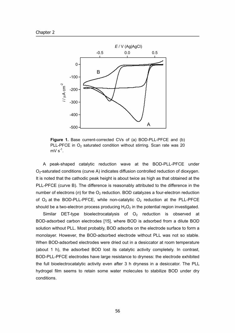
Chapter 2
-500
-400
-300
-200
-100
0i /
μA
cm
-2
-0.5 0.0 0.5E / V (Ag|AgCl)
A
B
Figure 1. Base current-corrected CVs of (a) BOD-PLL-PFCE and (b) PLL-PFCE in O2 saturated condition without stirring. Scan rate was 20 mV s-1.
A peak-shaped catalytic reduction wave at the BOD-PLL-PFCE under O2-saturated conditions (curve A) indicates diffusion controlled reduction of dioxygen. It is noted that the cathodic peak height is about twice as high as that obtained at the PLL-PFCE (curve B). The difference is reasonably attributed to the difference in the number of electrons (n) for the O2 reduction. BOD catalyzes a four-electron reduction of O2 at the BOD-PLL-PFCE, while non-catalytic O2 reduction at the PLL-PFCE should be a two-electron process producing H2O2 in the potential region investigated.
Similar DET-type bioelectrocatalysis of O2 reduction is observed at BOD-adsorbed carbon electrodes [15], where BOD is adsorbed from a dilute BOD solution without PLL. Most probably, BOD adsorbs on the electrode surface to form a monolayer. However, the BOD-adsorbed electrode without PLL was not so stable. When BOD-adsorbed electrodes were dried out in a desiccator at room temperature (about 1 h), the adsorbed BOD lost its catalytic activity completely. In contrast, BOD-PLL-PFCE electrodes have large resistance to dryness: the electrode exhibited the full bioelectrocatalytic activity even after 3 h dryness in a desiccator. The PLL hydrogel film seems to retain some water molecules to stabilize BOD under dry conditions.
56
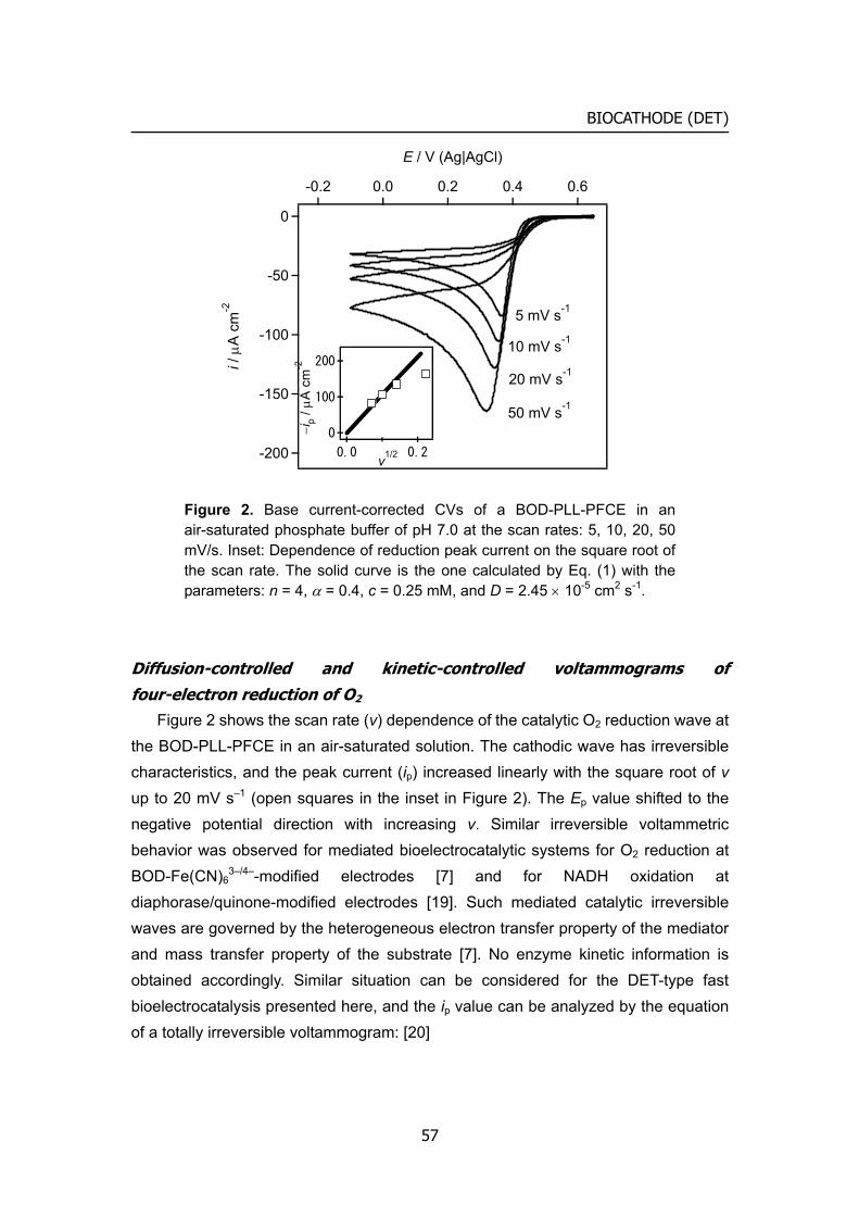
BIOCATHODE (DET)
-200
-150
-100
-50
0i /
μA
cm
-2
0.60.40.20.0-0.2
E / V (Ag|AgCl)
5 mV s-1
20 mV s-1
50 mV s-1
10 mV s-1
200
100
0−ip
/ μA
cm
-2
0.20.0 v1/2
Figure 2. Base current-corrected CVs of a BOD-PLL-PFCE in an air-saturated phosphate buffer of pH 7.0 at the scan rates: 5, 10, 20, 50 mV/s. Inset: Dependence of reduction peak current on the square root of the scan rate. The solid curve is the one calculated by Eq. (1) with the parameters: n = 4, α = 0.4, c = 0.25 mM, and D = 2.45 × 10⁻⁵ cm2 s-1.
Diffusion-controlled and kinetic-controlled voltammograms of four-electron reduction of O2
Figure 2 shows the scan rate (v) dependence of the catalytic O2 reduction wave at the BOD-PLL-PFCE in an air-saturated solution. The cathodic wave has irreversible characteristics, and the peak current (ip) increased linearly with the square root of v up to 20 mV s–1 (open squares in the inset in Figure 2). The Ep value shifted to the negative potential direction with increasing v. Similar irreversible voltammetric behavior was observed for mediated bioelectrocatalytic systems for O2 reduction at BOD-Fe(CN)6
3–/4–-modified electrodes [7] and for NADH oxidation at diaphorase/quinone-modified electrodes [19]. Such mediated catalytic irreversible waves are governed by the heterogeneous electron transfer property of the mediator and mass transfer property of the substrate [7]. No enzyme kinetic information is obtained accordingly. Similar situation can be considered for the DET-type fast bioelectrocatalysis presented here, and the ip value can be analyzed by the equation of a totally irreversible voltammogram: [20]
57
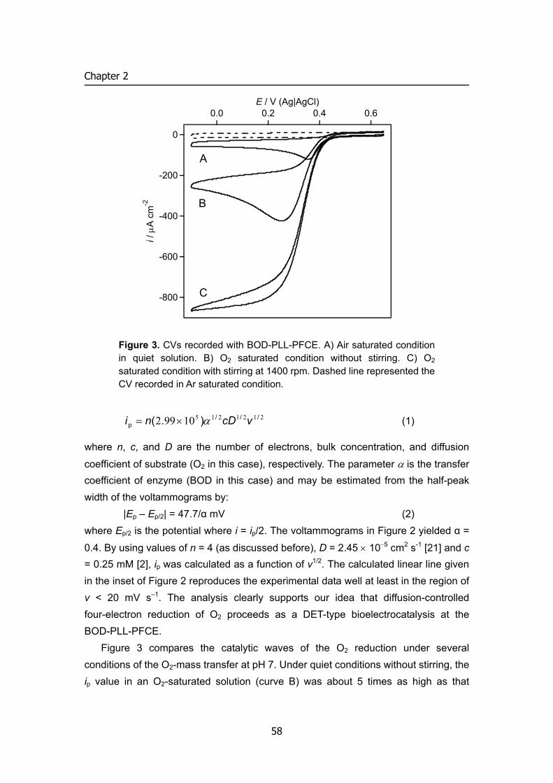
Chapter 2
-800
-600
-400
-200
0i /
μA
cm
-2
0.60.40.20.0E / V (Ag|AgCl)
C
B
A
Figure 3. CVs recorded with BOD-PLL-PFCE. A) Air saturated condition in quiet solution. B) O2 saturated condition without stirring. C) O2 saturated condition with stirring at 1400 rpm. Dashed line represented the CV recorded in Ar saturated condition.
212121510992 ///p ).( vcDni α×= (1)
where n, c, and D are the number of electrons, bulk concentration, and diffusion
coefficient of substrate (O2 in this case), respectively. The parameter α is the transfer coefficient of enzyme (BOD in this case) and may be estimated from the half-peak width of the voltammograms by:
|Ep – Ep/2| = 47.7/α mV (2) where Ep/2 is the potential where i = ip/2. The voltammograms in Figure 2 yielded α =
0.4. By using values of n = 4 (as discussed before), D = 2.45 × 10⁻⁵ cm2 s-1 [21] and c = 0.25 mM [2], ip was calculated as a function of v1/2. The calculated linear line given in the inset of Figure 2 reproduces the experimental data well at least in the region of v < 20 mV s–1. The analysis clearly supports our idea that diffusion-controlled four-electron reduction of O2 proceeds as a DET-type bioelectrocatalysis at the BOD-PLL-PFCE.
Figure 3 compares the catalytic waves of the O2 reduction under several conditions of the O2-mass transfer at pH 7. Under quiet conditions without stirring, the ip value in an O2-saturated solution (curve B) was about 5 times as high as that
58
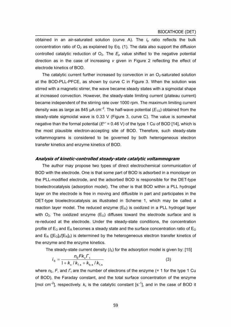
BIOCATHODE (DET)
obtained in an air-saturated solution (curve A). The ip ratio reflects the bulk concentration ratio of O2 as explained by Eq. (1). The data also support the diffusion controlled catalytic reduction of O2. The Ep value shifted to the negative potential direction as in the case of increasing v given in Figure 2 reflecting the effect of electrode kinetics of BOD.
The catalytic current further increased by convection in an O2-saturated solution at the BOD-PLL-PFCE, as shown by curve C in Figure 3. When the solution was stirred with a magnetic stirrer, the wave became steady states with a sigmoidal shape at increased convection. However, the steady-state limiting current (plateau current) became independent of the stirring rate over 1000 rpm. The maximum limiting current density was as large as 845 μA cm–2. The half-wave potential (E1/2) obtained from the steady-state sigmoidal wave is 0.33 V (Figure 3, curve C). The value is somewhat
negative than the formal potential (E°’ = 0.46 V) of the type 1 Cu of BOD [14], which is the most plausible electron-accepting site of BOD. Therefore, such steady-state voltammograms is considered to be governed by both heterogeneous electron transfer kinetics and enzyme kinetics of BOD.
Analysis of kinetic-controlled steady-state catalytic voltammogram The author may propose two types of direct electrochemical communication of
BOD with the electrode. One is that some part of BOD is adsorbed in a monolayer on the PLL-modified electrode, and the adsorbed BOD is responsible for the DET-type bioelectrocatalysis (adsorption model). The other is that BOD within a PLL hydrogel layer on the electrode is free in moving and diffusible in part and participates in the DET-type bioelectrocatalysis as illustrated in Scheme 1, which may be called a reaction layer model. The reduced enzyme (ER) is oxidized in a PLL hydrogel layer with O2. The oxidized enzyme (EO) diffuses toward the electrode surface and is re-reduced at the electrode. Under the steady-state conditions, the concentration profile of EO and ER becomes a steady state and the surface concentration ratio of EO and ER ([EO]0/[ER]0) is determined by the heterogeneous electron transfer kinetics of the enzyme and the enzyme kinetics.
The steady-state current density (IS) for the adsorption model is given by: [15]
s f,s b,s f,c
tcES // kkkk
ΓFkni
++=
1 (3)
where nE, F, and Γt are the number of electrons of the enzyme (= 1 for the type 1 Cu of BOD), the Faraday constant, and the total surface concentration of the enzyme [mol cm–2], respectively. kc is the catalytic constant [s–1], and in the case of BOD it
59
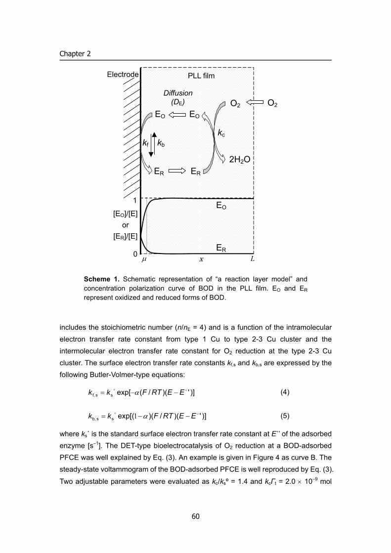
Chapter 2
includes the stoichiometric number (n/nE = 4) and is a function of the intramolecular electron transfer rate constant from type 1 Cu to type 2-3 Cu cluster and the intermolecular electron transfer rate constant for O2 reduction at the type 2-3 Cu cluster. The surface electron transfer rate constants kf,s and kb,s are expressed by the following Butler-Volmer-type equations:
)]')(/(exp[ss f,oo EERTFkk −−= α (4)
)]')(/)(exp[(ss b,oo EERTFkk −−= α1 (5)
where ks˚ is the standard surface electron transfer rate constant at E˚’ of the adsorbed enzyme [s–1]. The DET-type bioelectrocatalysis of O2 reduction at a BOD-adsorbed PFCE was well explained by Eq. (3). An example is given in Figure 4 as curve B. The steady-state voltammogram of the BOD-adsorbed PFCE is well reproduced by Eq. (3).
Two adjustable parameters were evaluated as kc/ksº = 1.4 and kcΓt = 2.0 × 10⁻⁹ mol
EO
ER
EO O2 O2
ER
EO
ER
[EO]/[E] or
[ER]/[E]
2H2O
PLL film
0
1
Electrode
kc
Diffusion (DE)
kf kb
μ x L
Scheme 1. Schematic representation of “a reaction layer model” and concentration polarization curve of BOD in the PLL film. EO and ER represent oxidized and reduced forms of BOD.
60

BIOCATHODE (DET)
s–1 cm–2. The regression curve is depicted open squares in Figure 4, curve B [15]. When the steady-state voltammogram at the BOD-PLL-PFCE was fitted to Eq. (3)
using a non-linear regression analysis program (Excel®), the adjustable parameters
kc/ksº and kcΓt were evaluated as 13 and 8.9 × 10⁻⁹ mol cm–2 s–1, respectively, where α was fixed as an allowable value of 0.5. Assuming kc value to be identical with the maximum catalytic constant of BOD in solution (250 s–1) [22], the Γt and ks˚ values were calculated as 38 pmol cm–2 and 18 s–1, respectively. Considering the crystallographic structure of a fungal laccase from Trametes versicolor with a
molecular mass of ca. 70 kDa (roughly evaluated dimension of 65 × 55 × 45 Å) [23], Γt of BOD can be calculated as 5-7 pmol cm–2 at the most by ignoring the orientation of adsorbed states of BOD, though the roughness factor of electrode surface is not taken into account. This calculated maximum value is much smaller than that evaluated based on Eq. (3). The author can safely conclude that the adsorption model is not appropriate for explaining the steady-state voltammogram of DET-type bioelectrocatalysis for O2 reduction at the BOD-PLL-PFCE.
The IS value for the reaction layer model is given by:
fbfc
cES //
[E]kkkk
kFnI++
=μ
μ1
(6)
with )]')(/(exp[f
oo EERTFkk −−= α (7)
)]')(/)(exp[(boo EERTFkk −−= α1 (8)
where [E] is the total concentration of the enzyme in the enzyme layer, μ is the reaction layer thickness (the distance x at which the concentration of [ER]x = [ER]0/e:
[ER]0 being the surface concentration of ER) and is given by cE / kD=μ ; DE being
the diffusion coefficient of the enzyme in the immobilized enzyme layer. k˚ is now the standard electron transfer rate constant at E˚’ [cm s–1]. The derivation of Eq. (6) is summarized in Appendix.
The experimental steady-state voltammogram (Figure 4, curve A) was fitted to Eq. (6) with adjustable parameters of [E]kcμ and kc/k˚ using the non-linear regression analysis program. The α value was assumed to be 0.5. The best fit was obtained with [E]kcμ = 8.9 × 10⁻⁹ mol cm–2 s–1and kcμ/k˚ = 13, respectively, as shown as open circles on curve A in Figure 4. Assuming the kc value again to be 250 s–1 and the D value to be 1×10⁻⁷ cm2 s–1, the reaction layer thickness is calculated as 0.2 μm. The value is sufficiently small than the film thickness of the BOD-PLL layer (50 μm), which was
61
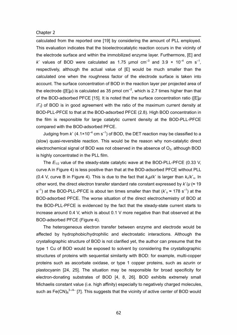
Chapter 2
calculated from the reported one [19] by considering the amount of PLL employed. This evaluation indicates that the bioelectrocatalytic reaction occurs in the vicinity of the electrode surface and within the immobilized enzyme layer. Furthermore, [E] and k˚ values of BOD were calculated as 1.75 μmol cm–3 and 3.9 × 10⁻⁴ cm s–1, respectively, although the actual value of [E] would be much smaller than the calculated one when the roughness factor of the electrode surface is taken into account. The surface concentration of BOD in the reaction layer per projected area of the electrode ([E]μ) is calculated as 35 pmol cm–2, which is 2.7 times higher than that of the BOD-adsorbed PFCE [15]. It is noted that the surface concentration ratio ([E]μ /Γt) of BOD is in good agreement with the ratio of the maximum current density at BOD-PLL-PFCE to that at the BOD-adsorbed PFCE (2.8). High BOD concentration in the film is responsible for large catalytic current density at the BOD-PLL-PFCE compared with the BOD-adsorbed PFCE.
Judging from k˚ (4.1×10⁻⁴ cm s–1) of BOD, the DET reaction may be classified to a (slow) quasi-reversible reaction. This would be the reason why non-catalytic direct electrochemical signal of BOD was not observed in the absence of O2, although BOD is highly concentrated in the PLL film.
The E1/2 value of the steady-state catalytic wave at the BOD-PLL-PFCE (0.33 V, curve A in Figure 4) is less positive than that at the BOD-adsorbed PFCE without PLL (0.4 V, curve B in Figure 4). This is due to the fact that kcμ/k˚ is larger than kc/k˚s. In other word, the direct electron transfer standard rate constant expressed by k˚/μ (≈ 19 s–1) at the BOD-PLL-PFCE is about ten times smaller than that (k˚s ≈ 178 s–1) at the BOD-adsorbed PFCE. The worse situation of the direct electrochemistry of BOD at the BOD-PLL-PFCE is evidenced by the fact that the steady-state current starts to increase around 0.4 V, which is about 0.1 V more negative than that observed at the BOD-adsorbed PFCE (Figure 4).
The heterogeneous electron transfer between enzyme and electrode would be affected by hydrophobic/hydrophilic and electrostatic interactions. Although the crystallographic structure of BOD is not clarified yet, the author can presume that the type 1 Cu of BOD would be exposed to solvent by considering the crystallographic structures of proteins with sequential similarity with BOD: for example, multi-copper proteins such as ascorbate oxidase, or type 1 copper proteins, such as azurin or plastocyanin [24, 25]. The situation may be responsible for broad specificity for electron-donating substrates of BOD [4, 8, 26]. BOD exhibits extremely small Michaelis constant value (i.e. high affinity) especially to negatively charged molecules, such as Fe(CN)6
3–/4– [7]. This suggests that the vicinity of active center of BOD would
62
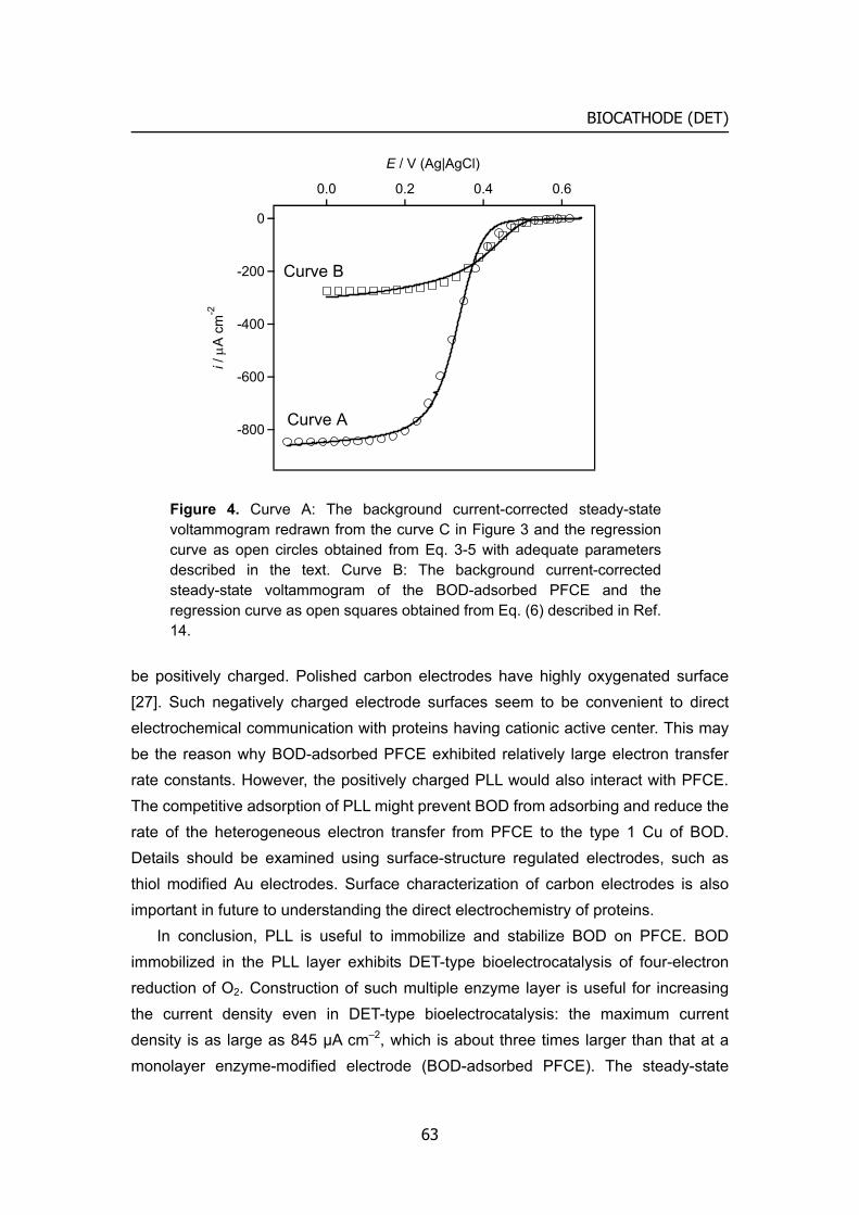
BIOCATHODE (DET)
-800
-600
-400
-200
0i /
μA
cm
-2
0.60.40.20.0
E / V (Ag|AgCl)
Curve A
Curve B
Figure 4. Curve A: The background current-corrected steady-state voltammogram redrawn from the curve C in Figure 3 and the regression curve as open circles obtained from Eq. 3-5 with adequate parameters described in the text. Curve B: The background current-corrected steady-state voltammogram of the BOD-adsorbed PFCE and the regression curve as open squares obtained from Eq. (6) described in Ref. 14.
be positively charged. Polished carbon electrodes have highly oxygenated surface [27]. Such negatively charged electrode surfaces seem to be convenient to direct electrochemical communication with proteins having cationic active center. This may be the reason why BOD-adsorbed PFCE exhibited relatively large electron transfer rate constants. However, the positively charged PLL would also interact with PFCE. The competitive adsorption of PLL might prevent BOD from adsorbing and reduce the rate of the heterogeneous electron transfer from PFCE to the type 1 Cu of BOD. Details should be examined using surface-structure regulated electrodes, such as thiol modified Au electrodes. Surface characterization of carbon electrodes is also important in future to understanding the direct electrochemistry of proteins.
In conclusion, PLL is useful to immobilize and stabilize BOD on PFCE. BOD immobilized in the PLL layer exhibits DET-type bioelectrocatalysis of four-electron reduction of O2. Construction of such multiple enzyme layer is useful for increasing the current density even in DET-type bioelectrocatalysis: the maximum current density is as large as 845 μA cm–2, which is about three times larger than that at a monolayer enzyme-modified electrode (BOD-adsorbed PFCE). The steady-state
63
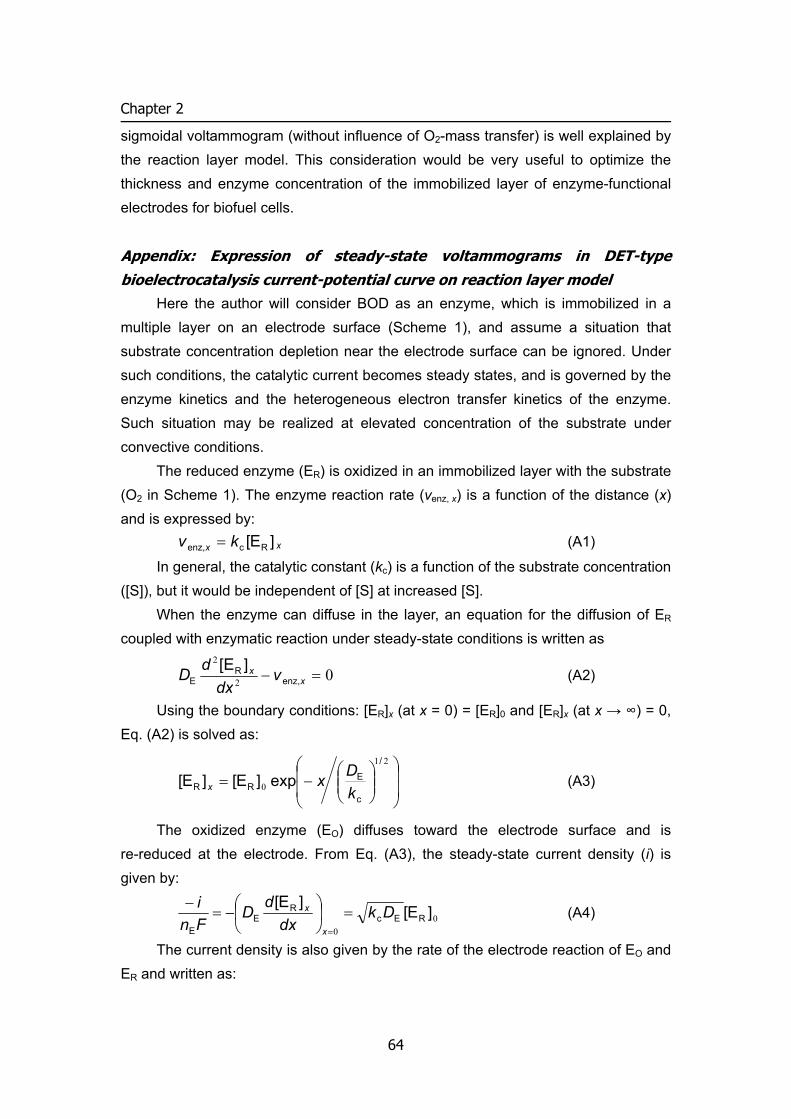
Chapter 2
sigmoidal voltammogram (without influence of O2-mass transfer) is well explained by the reaction layer model. This consideration would be very useful to optimize the thickness and enzyme concentration of the immobilized layer of enzyme-functional electrodes for biofuel cells.
Appendix: Expression of steady-state voltammograms in DET-type bioelectrocatalysis current-potential curve on reaction layer model
Here the author will consider BOD as an enzyme, which is immobilized in a multiple layer on an electrode surface (Scheme 1), and assume a situation that substrate concentration depletion near the electrode surface can be ignored. Under such conditions, the catalytic current becomes steady states, and is governed by the enzyme kinetics and the heterogeneous electron transfer kinetics of the enzyme. Such situation may be realized at elevated concentration of the substrate under convective conditions.
The reduced enzyme (ER) is oxidized in an immobilized layer with the substrate (O2 in Scheme 1). The enzyme reaction rate (venz, x) is a function of the distance (x) and is expressed by:
]E[ Rcenz, kv x = x (A1)
In general, the catalytic constant (kc) is a function of the substrate concentration ([S]), but it would be independent of [S] at increased [S].
When the enzyme can diffuse in the layer, an equation for the diffusion of ER coupled with enzymatic reaction under steady-state conditions is written as
02
2
=− xx v
dxdD enz,
RE
][E (A2)
Using the boundary conditions: [ER]x (at x = 0) = [ER]0 and [ER]x (at x → ∞) = 0, Eq. (A2) is solved as:
⎟⎟
⎠
⎞
⎜⎜
⎝
⎛⎟⎟⎠
⎞⎜⎜⎝
⎛−=
21
0
/
c
ERR exp]E[]E[
kDxx (A3)
The oxidized enzyme (EO) diffuses toward the electrode surface and is re-reduced at the electrode. From Eq. (A3), the steady-state current density (i) is given by:
00
]E[]E[REc
RE
E
Dkdx
dDFni
x
x =⎟⎠
⎞⎜⎝
⎛−=−
=
(A4)
The current density is also given by the rate of the electrode reaction of EO and ER and written as:
64
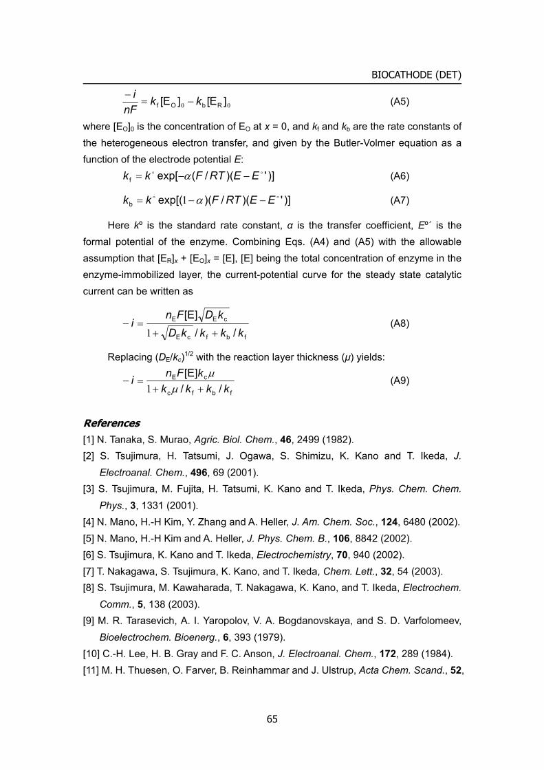
BIOCATHODE (DET)
00 ]E[]E[ RbOf kknF
i−=
− (A5)
where [EO]0 is the concentration of EO at x = 0, and kf and kb are the rate constants of the heterogeneous electron transfer, and given by the Butler-Volmer equation as a function of the electrode potential E:
)]')(/(exp[foo EERTFkk −−= α (A6)
)]')(/)(exp[(boo EERTFkk −−= α1 (A7)
Here kº is the standard rate constant, α is the transfer coefficient, Eº´ is the formal potential of the enzyme. Combining Eqs. (A4) and (A5) with the allowable assumption that [ER]x + [EO]x = [E], [E] being the total concentration of enzyme in the enzyme-immobilized layer, the current-potential curve for the steady state catalytic current can be written as
fbfcE
cEE
//[E]
kkkkDkDFn
i++
=−1
(A8)
Replacing (DE/kc)1/2 with the reaction layer thickness (μ) yields:
fbfc
cE
//[E]
kkkkkFn
i++
=−μ
μ1
(A9)
References [1] N. Tanaka, S. Murao, Agric. Biol. Chem., 46, 2499 (1982). [2] S. Tsujimura, H. Tatsumi, J. Ogawa, S. Shimizu, K. Kano and T. Ikeda, J.
Electroanal. Chem., 496, 69 (2001). [3] S. Tsujimura, M. Fujita, H. Tatsumi, K. Kano and T. Ikeda, Phys. Chem. Chem.
Phys., 3, 1331 (2001). [4] N. Mano, H.-H Kim, Y. Zhang and A. Heller, J. Am. Chem. Soc., 124, 6480 (2002). [5] N. Mano, H.-H Kim and A. Heller, J. Phys. Chem. B., 106, 8842 (2002). [6] S. Tsujimura, K. Kano and T. Ikeda, Electrochemistry, 70, 940 (2002). [7] T. Nakagawa, S. Tsujimura, K. Kano, and T. Ikeda, Chem. Lett., 32, 54 (2003). [8] S. Tsujimura, M. Kawaharada, T. Nakagawa, K. Kano, and T. Ikeda, Electrochem.
Comm., 5, 138 (2003). [9] M. R. Tarasevich, A. I. Yaropolov, V. A. Bogdanovskaya, and S. D. Varfolomeev,
Bioelectrochem. Bioenerg., 6, 393 (1979). [10] C.-H. Lee, H. B. Gray and F. C. Anson, J. Electroanal. Chem., 172, 289 (1984). [11] M. H. Thuesen, O. Farver, B. Reinhammar and J. Ulstrup, Acta Chem. Scand., 52,
65
Chapter 2
555 (1998). [12] A. I. Yaropolov, A. N. Kharybin, J. Emnéus, G. Marko-Varga, and L. Gorton,
Bioelectrochem. Bioenerg., 40, 49 (1996). [13] D. L. Johnson, J. L. Thomptson, S. M. Brinkmann, K. A. Schuller, and L. L. Martin,
Biochemistry, 42, 10229 (2003). [14] A. Kuriyama, M. Arasaki, N. Fujieda, S. Tsujimura, K. Kano, and T. Ikeda, Rev.
Polarogr., 49, 192 (2003) (in Japanese). [15] S. Tsujimura, T. Nakagawa, K. Kano, and T. Ikeda, Electrochemistry, 72, 437
(2004). [16] T. Kawakubo, Y. Suda, H. Kaneko, A. Negishi, and M. Yamada, Tanso, 152, 106
(1992) (in Japanese). [17] H. Kaneko, A. Negishi, Y. Suda, and T. Kawakubo, Denki Kagaku (presently
Electrochemistry) 61, 920 (1993). [18] T. Kawakubo, Y. Suda, A. Negishi, and H. Kaneko, Tanso, 169, 201 (1995) (in
Japanese). [19] A. Sato, K. Kano, and T. Ikeda, Chem. Lett., 32, 880 (2003). [20] A. J. Bard and L. R. Faukner, Electrochemical Methods, Fundamentals and
Applications, Second ed. Wiley, New York, pp. 236 (2001). [21] M. Tsushima, K. Tokuda, T. Ohsaka, Anal. Chem., 66, 4551 (1994). [22] S. Tsujimura, K. Kano, and T. Ikeda, Proc. 204th Meeting of the Electrochemical
Society, Orland, FL., 12-16, Oct., p.1230 (2003). [23] K. Pionetek, M. Antorini, and T. Choinowski, J. Biol. Chem., 277, 37663 (2002). [24] E. I. Solomon, U. M. Sundaram, and T. E. Machonkin, Chem. Rev., 96, 2563
(1996). [25] F. J. Enguita, L. O. Martins, A. O. Henriques, and M. A. Carrondo, J. Biol. Chem.,
278, 19416 (2003). [26] F. Xu, W. Shin, S. H. Brown, J. A. Wahleithner, U. M. Sundaram, E. I. Solomon,
Biochim. Biophys. Acta., 1292, 303 (1996). [27] R. L. McCreery, in: A. J. Bard, (Ed.), Electroanalytical Chemistry vol. 17, Dekker,
New York, 1984, pp. 221-374.
66
3
Bioanode Electro-enzymatic oxidation of biological fuels
A new redox polymer containing Os (E°’ = –0.15 V vs. Ag|AgCl) was designed and
synthesized as an efficient mediator of diaphorase-catalyzed electrochemical oxidation
of NADH and glucose, and as a support to immobilize enzyme(s) on electrode surfaces.
The electrochemical characteristics of the polymer and its application to biosensors
and bioanodes of biofuel cells are briefed.
Introduction
Electrochemical oxidation of NADH has been a subject receiving great attention in views of biosensors and biofuel cells [1-3], since NAD-dependent enzymes constitute the largest group of redox enzymes. Because the direct electrochemical oxidation of NADH requires large overpotential [4], organic or inorganic compounds may be used as non-enzymatic catalysts [1]. More efficient catalytic systems are mediated bioelectrocatalysis consisting of suitable enzymes and mediators. Diaphorase is frequently used for this purpose, and several metal complexes [5], quinines [6] and also viologens [3] have been utilized as mediators. The electron transferring relays from a reduced substrate to an electrode is illustrated in scheme 1. The formal
potential of mediator (E°’M) and the rate constant between diaphorase and mediator (kM) are important factors; the more negative in E°’M and the larger in kM, the better the mediator is. Considering the fact that kM increases exponentially with E°’M and reaches the diffusion-controlled limiting value at increased E°’M [6], vitamin K3 is one of the most promising mediators with more negative E°’M among the mediators with diffusion-controlled value of kM [6, 7]. However, vitamin K3 has serious drawbacks in O2-sensitive property of the reduced form [8] and difficulty in the immobilization on
67
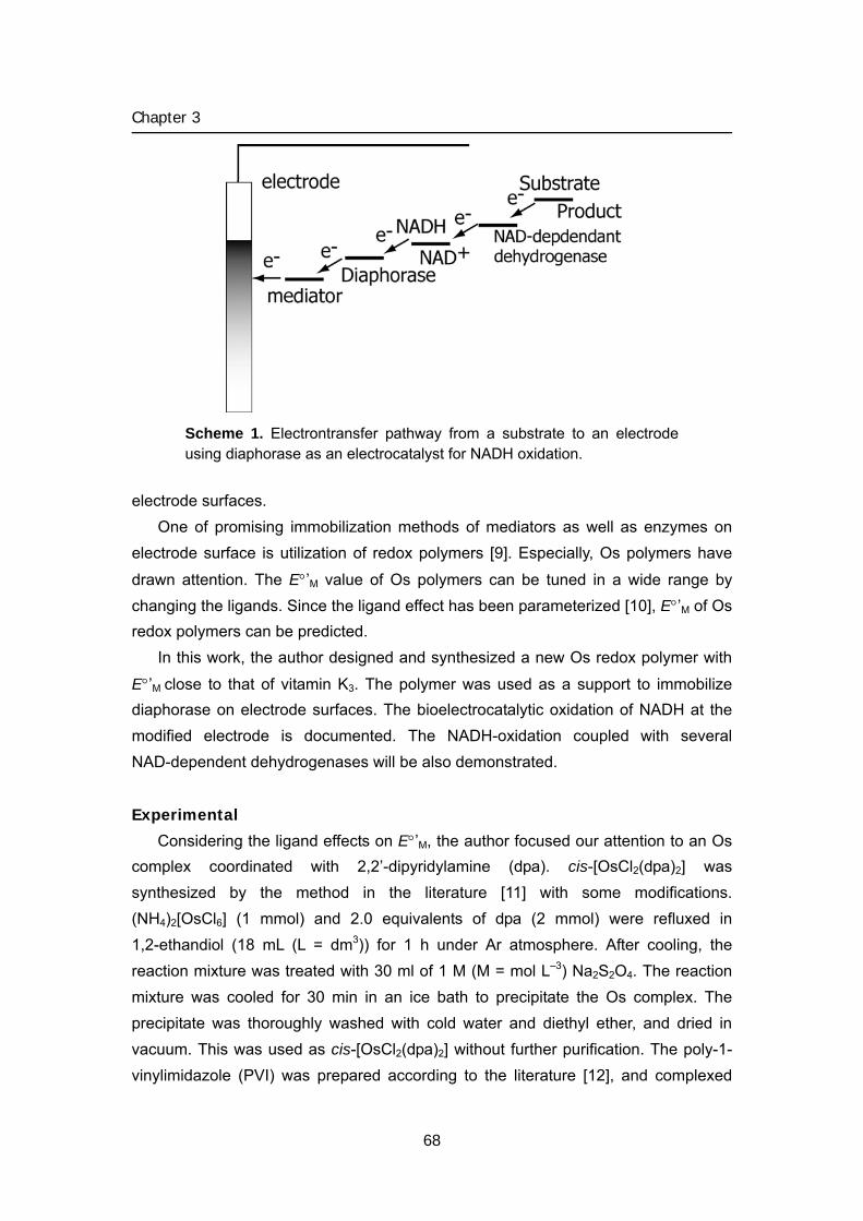
Chapter 3
Scheme 1. Electrontransfer pathway from a substrate to an electrode using diaphorase as an electrocatalyst for NADH oxidation.
electrode surfaces. One of promising immobilization methods of mediators as well as enzymes on
electrode surface is utilization of redox polymers [9]. Especially, Os polymers have
drawn attention. The E°’M value of Os polymers can be tuned in a wide range by changing the ligands. Since the ligand effect has been parameterized [10], E°’M of Os redox polymers can be predicted.
In this work, the author designed and synthesized a new Os redox polymer with
E°’M close to that of vitamin K3. The polymer was used as a support to immobilize diaphorase on electrode surfaces. The bioelectrocatalytic oxidation of NADH at the modified electrode is documented. The NADH-oxidation coupled with several NAD-dependent dehydrogenases will be also demonstrated.
Experimental
Considering the ligand effects on E°’M, the author focused our attention to an Os complex coordinated with 2,2’-dipyridylamine (dpa). cis-[OsCl2(dpa)2] was synthesized by the method in the literature [11] with some modifications. (NH4)2[OsCl6] (1 mmol) and 2.0 equivalents of dpa (2 mmol) were refluxed in 1,2-ethandiol (18 mL (L = dm3)) for 1 h under Ar atmosphere. After cooling, the reaction mixture was treated with 30 ml of 1 M (M = mol L–3) Na2S2O4. The reaction mixture was cooled for 30 min in an ice bath to precipitate the Os complex. The precipitate was thoroughly washed with cold water and diethyl ether, and dried in vacuum. This was used as cis-[OsCl2(dpa)2] without further purification. The poly-1- vinylimidazole (PVI) was prepared according to the literature [12], and complexed
68
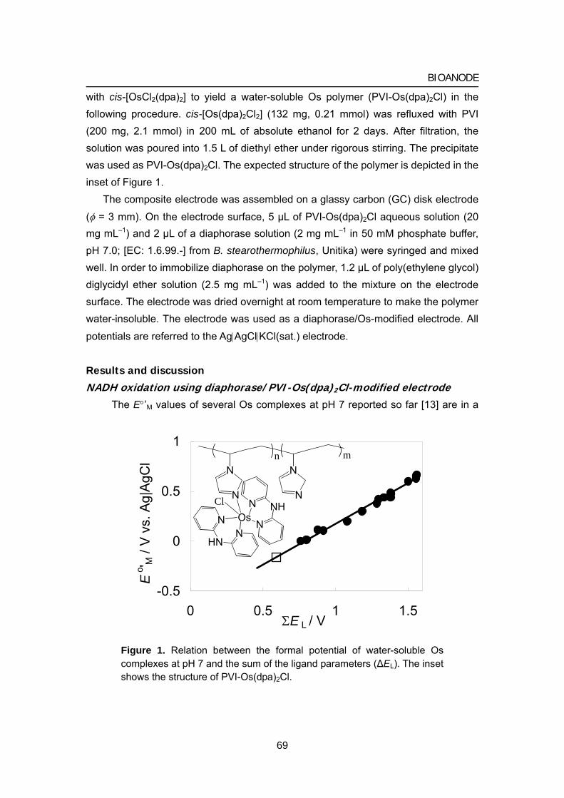
BIOANODE
with cis-[OsCl2(dpa)2] to yield a water-soluble Os polymer (PVI-Os(dpa)2Cl) in the following procedure. cis-[Os(dpa)2Cl2] (132 mg, 0.21 mmol) was refluxed with PVI (200 mg, 2.1 mmol) in 200 mL of absolute ethanol for 2 days. After filtration, the solution was poured into 1.5 L of diethyl ether under rigorous stirring. The precipitate was used as PVI-Os(dpa)2Cl. The expected structure of the polymer is depicted in the inset of Figure 1.
The composite electrode was assembled on a glassy carbon (GC) disk electrode
(φ = 3 mm). On the electrode surface, 5 μL of PVI-Os(dpa)2Cl aqueous solution (20 mg mL–1) and 2 μL of a diaphorase solution (2 mg mL–1 in 50 mM phosphate buffer, pH 7.0; [EC: 1.6.99.-] from B. stearothermophilus, Unitika) were syringed and mixed well. In order to immobilize diaphorase on the polymer, 1.2 μL of poly(ethylene glycol) diglycidyl ether solution (2.5 mg mL–1) was added to the mixture on the electrode surface. The electrode was dried overnight at room temperature to make the polymer water-insoluble. The electrode was used as a diaphorase/Os-modified electrode. All
potentials are referred to the Ag|AgCl|KCl(sat.) electrode.
Results and discussion
NADH oxidation using diaphorase/PVI-Os(dpa)2Cl-modified electrode The E°’M values of several Os complexes at pH 7 reported so far [13] are in a
-0.5
0
0.5
1
0 0.5 1 1.ΣE L / V
Eo ' M
/ V
vs.
Ag|
AgC
l
5
N
N
OsN NH
NN
HN
N
Cl
N
N
n m
Figure 1. Relation between the formal potential of water-soluble Os complexes at pH 7 and the sum of the ligand parameters (ΔEL). The inset shows the structure of PVI-Os(dpa)2Cl.
69
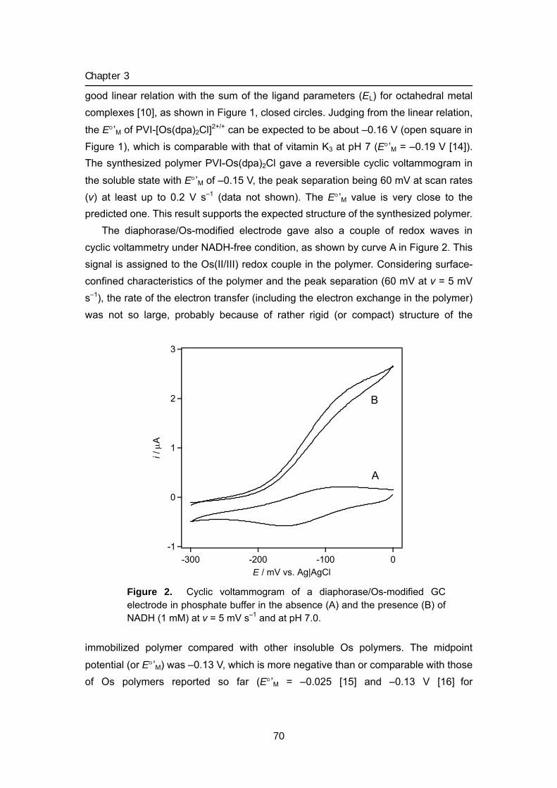
Chapter 3
good linear relation with the sum of the ligand parameters (EL) for octahedral metal complexes [10], as shown in Figure 1, closed circles. Judging from the linear relation,
the E°’M of PVI-[Os(dpa)2Cl]2+/+ can be expected to be about –0.16 V (open square in Figure 1), which is comparable with that of vitamin K3 at pH 7 (E°’M = –0.19 V [14]). The synthesized polymer PVI-Os(dpa)2Cl gave a reversible cyclic voltammogram in
the soluble state with E°’M of –0.15 V, the peak separation being 60 mV at scan rates (v) at least up to 0.2 V s–1 (data not shown). The E°’M value is very close to the predicted one. This result supports the expected structure of the synthesized polymer.
The diaphorase/Os-modified electrode gave also a couple of redox waves in cyclic voltammetry under NADH-free condition, as shown by curve A in Figure 2. This signal is assigned to the Os(II/III) redox couple in the polymer. Considering surface- confined characteristics of the polymer and the peak separation (60 mV at v = 5 mV s–1), the rate of the electron transfer (including the electron exchange in the polymer) was not so large, probably because of rather rigid (or compact) structure of the
immobilized polymer compared with other insoluble Os polymers. The midpoint
potential (or E°’M) was –0.13 V, which is more negative than or comparable with those of Os polymers reported so far (E°’M = –0.025 [15] and –0.13 V [16] for
3
2
1
0
-1
i / μ
A
-300 -200 -100 0E / mV vs. Ag|AgCl
A
B
Figure 2. Cyclic voltammogram of a diaphorase/Os-modified GC electrode in phosphate buffer in the absence (A) and the presence (B) of NADH (1 mM) at v = 5 mV s–1 and at pH 7.0.
70
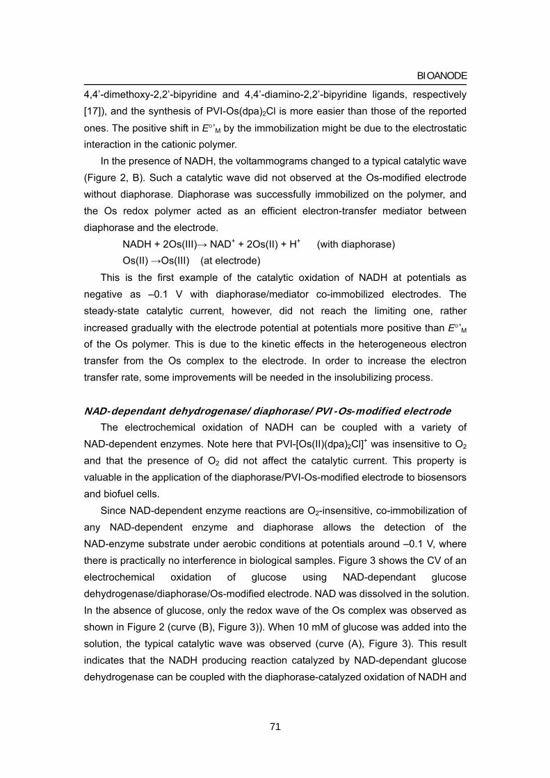
BIOANODE
4,4’-dimethoxy-2,2’-bipyridine and 4,4’-diamino-2,2’-bipyridine ligands, respectively [17]), and the synthesis of PVI-Os(dpa)2Cl is more easier than those of the reported
ones. The positive shift in E°’M by the immobilization might be due to the electrostatic interaction in the cationic polymer.
In the presence of NADH, the voltammograms changed to a typical catalytic wave (Figure 2, B). Such a catalytic wave did not observed at the Os-modified electrode without diaphorase. Diaphorase was successfully immobilized on the polymer, and the Os redox polymer acted as an efficient electron-transfer mediator between diaphorase and the electrode.
NADH + 2Os(III)→ NAD+ + 2Os(II) + H+ (with diaphorase) Os(II) →Os(III) (at electrode)
This is the first example of the catalytic oxidation of NADH at potentials as negative as –0.1 V with diaphorase/mediator co-immobilized electrodes. The steady-state catalytic current, however, did not reach the limiting one, rather
increased gradually with the electrode potential at potentials more positive than E°’M of the Os polymer. This is due to the kinetic effects in the heterogeneous electron transfer from the Os complex to the electrode. In order to increase the electron transfer rate, some improvements will be needed in the insolubilizing process.
NAD-dependant dehydrogenase/diaphorase/PVI-Os-modified electrode The electrochemical oxidation of NADH can be coupled with a variety of
NAD-dependent enzymes. Note here that PVI-[Os(II)(dpa)2Cl]+ was insensitive to O2 and that the presence of O2 did not affect the catalytic current. This property is valuable in the application of the diaphorase/PVI-Os-modified electrode to biosensors and biofuel cells.
Since NAD-dependent enzyme reactions are O2-insensitive, co-immobilization of any NAD-dependent enzyme and diaphorase allows the detection of the NAD-enzyme substrate under aerobic conditions at potentials around –0.1 V, where there is practically no interference in biological samples. Figure 3 shows the CV of an electrochemical oxidation of glucose using NAD-dependant glucose dehydrogenase/diaphorase/Os-modified electrode. NAD was dissolved in the solution. In the absence of glucose, only the redox wave of the Os complex was observed as shown in Figure 2 (curve (B), Figure 3)). When 10 mM of glucose was added into the solution, the typical catalytic wave was observed (curve (A), Figure 3). This result indicates that the NADH producing reaction catalyzed by NAD-dependant glucose dehydrogenase can be coupled with the diaphorase-catalyzed oxidation of NADH and
71
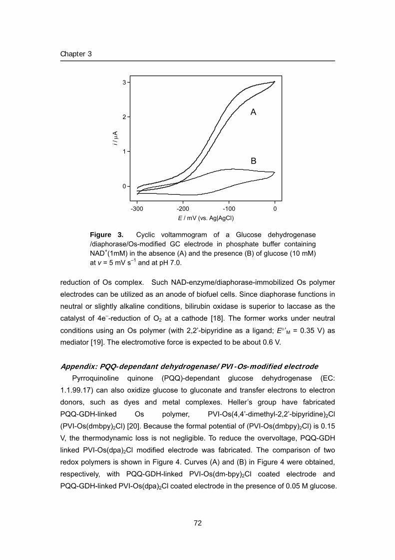
Chapter 3
3
2
1
0
i / μ
A
-300 -200 -100 0E / mV (vs. Ag|AgCl)
A
B
Figure 3. Cyclic voltammogram of a Glucose dehydrogenase /diaphorase/Os-modified GC electrode in phosphate buffer containing NAD+(1mM) in the absence (A) and the presence (B) of glucose (10 mM) at v = 5 mV s–1 and at pH 7.0.
reduction of Os complex. Such NAD-enzyme/diaphorase-immobilized Os polymer electrodes can be utilized as an anode of biofuel cells. Since diaphorase functions in neutral or slightly alkaline conditions, bilirubin oxidase is superior to laccase as the catalyst of 4e–-reduction of O2 at a cathode [18]. The former works under neutral
conditions using an Os polymer (with 2,2’-bipyridine as a ligand; E°’M = 0.35 V) as ediator [19]. The electromotive force is expected to be about 0.6 V.
Ap
m
pendix: PQQ-dependant dehydrogenase/PVI-Os-modified electrode Pyrroquinoline quinone (PQQ)-dependant glucose dehydrogenase (EC:
1.1.99.17) can also oxidize glucose to gluconate and transfer electrons to electron donors, such as dyes and metal complexes. Heller’s group have fabricated PQQ-GDH-linked Os polymer, PVI-Os(4,4’-dimethyl-2,2’-bipyridine)2Cl (PVI-Os(dmbpy)2Cl) [20]. Because the formal potential of (PVI-Os(dmbpy)2Cl) is 0.15 V, the thermodynamic loss is not negligible. To reduce the overvoltage, PQQ-GDH linked PVI-Os(dpa)2Cl modified electrode was fabricated. The comparison of two redox polymers is shown in Figure 4. Curves (A) and (B) in Figure 4 were obtained, respectively, with PQQ-GDH-linked PVI-Os(dm-bpy)2Cl coated electrode and PQQ-GDH-linked PVI-Os(dpa)2Cl coated electrode in the presence of 0.05 M glucose.
72
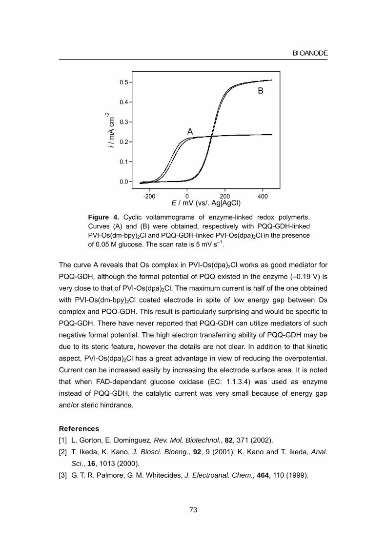
BIOANODE
0.5
0.4
0.3
0.2
0.1
0.0
i / m
A cm
-2
4002000-200E / mV (vs/. Ag|AgCl)
A
B
Figure 4. Cyclic voltammograms of enzyme-linked redox polymerts. Curves (A) and (B) were obtained, respectively with PQQ-GDH-linked PVI-Os(dm-bpy)2Cl and PQQ-GDH-linked PVI-Os(dpa)2Cl in the presence of 0.05 M glucose. The scan rate is 5 mV s–1.
The curve A reveals that Os complex in PVI-Os(dpa)2Cl works as good mediator for PQQ-GDH, although the formal potential of PQQ existed in the enzyme (–0.19 V) is very close to that of PVI-Os(dpa)2Cl. The maximum current is half of the one obtained with PVI-Os(dm-bpy)2Cl coated electrode in spite of low energy gap between Os complex and PQQ-GDH. This result is particularly surprising and would be specific to PQQ-GDH. There have never reported that PQQ-GDH can utilize mediators of such negative formal potential. The high electron transferring ability of PQQ-GDH may be due to its steric feature, however the details are not clear. In addition to that kinetic aspect, PVI-Os(dpa)2Cl has a great advantage in view of reducing the overpotential. Current can be increased easily by increasing the electrode surface area. It is noted that when FAD-dependant glucose oxidase (EC: 1.1.3.4) was used as enzyme instead of PQQ-GDH, the catalytic current was very small because of energy gap
nd/or steric hindrance.
[2] iosci. Bioeng., 92, 9 (2001); K. Kano and T. Ikeda, Anal.
a
References
[1] L. Gorton, E. Dominguez, Rev. Mol. Biotechnol., 82, 371 (2002). T. Ikeda, K. Kano, J. BSci., 16, 1013 (2000).
[3] G. T. R. Palmore, G. M. Whitecides, J. Electroanal. Chem., 464, 110 (1999).
73
Chapter 3
74
[4] 80); T. Matsue, M.
[5] ang, I. Uchida, K. Nagata, K. Tomita, Biochim.
[6] 1995); K. 8).
[9] hmidt, F. Gutberlet, W. Schuhmann, Sensor Actuat. B-Chem., 13/14, 366
[11] land, J. V. Caspar, K. R. Braqawi, T. J. Meyer,
[13
ang, T. Haruyama, E. Kobatake, M. 0).
[15 r, G. Kenausis, I. Katakis, A. Heller, J. Electroanal. Chem., 396, 511
[16 . Kim S. C. Barton, Y. Zhang, A. Heller, Angew. Chem.
[18Fujita, H. Tatsumi, K. Kano,
[20 W. Schuhmann, H. Schmidt, J. A. Duine, A. Heller, Anal. Chem., 65, 238 (1993).
J. Moiroux, P. J. Elving, J. Am. Chem. Soc., 102, 6533 (19Suda, and I. Uchida, J. Electroanal. Chem., 234, 163 (1987). T. Matsue, H. Yamada, H-C. ChBiophys. Acta, 1038, 29 (1990). Y. Ogino, K. Takagi, K. Kano, T. Ikeda, J. Electroanal. Chem., 396, 517 (Takagi, K. Kano, and T. Ikeda, J. Electroanal. Chem., 445, 211 (199
[7] K. Miki, T. Ikeda, S. Todoroki, M. Senda, Anal. Sci., 5, 269 (1989). [8] H. Tatsumi, H. Nakane, K. Kano, T. Ikeda, J. Electroanal. Chem., 443, 236 (1998).
H.-L. Sc(1993).
[10] A. B. P. Lever, Inorg. Chem., 29, 1271(1990). S. R. Johnson, T. D. WestmoreInorg. Chem., 27, 3195 (1988).
[12] T. J. Ohara, R. Rajagopalan, A. Heller, Anal. Chem., 65, 3512 (1993). ] Y. Nakabayashi, A. Omayu, S. Yagi, K. Nakamura, J. Motonaka, Anal. Sci., 17, 945 (2001); S. M. Zakeeruddin, D. M. Fraser, M-K. Nazeeruddin, M. Grätzel, J.
Electroanal. Chem., 337, 253 (1992); C. ZhAizawa, Anal. Chim. Acta, 408, 225 (200
[14] K. Kano, Rev. Polarogr., 48, 29 (2002). ] C. Taylo(1995).
] Z. Gao, G. Binyamin, H-H ,Int. Ed., 41, 810 (2002).
[17] B. G. Maerker, F. H. Case, J. Am. Chem. Soc., 80, 2745 (1958). ] S. Tsujimura, H. Tatsumi, J. Ogawa, S. Shimizu, K. Kano, and T. Ikeda, J.
Electroanal. Chem., 496, 69 (2001); S. Tsujimura, M. T. Ikeda, Phys. Chem. Chem. Phys., 3, 1331 (2001).
[19] S. Tsujimura, K. Kano, T. Ikeda, Electrochemistry, 70, 940 (2002). ] L. Ye, M. Hammerle, A. J. J. Olsthoorn,
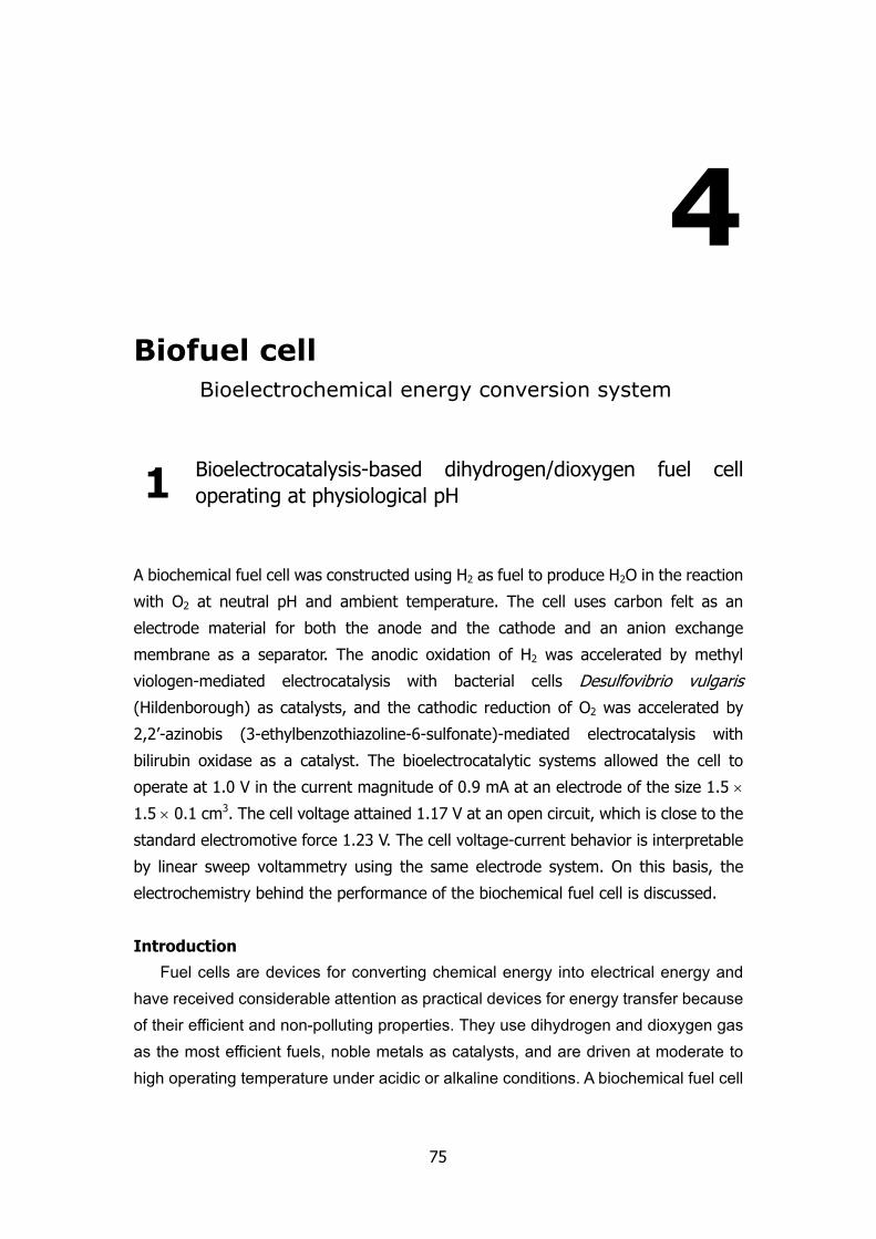
4
Biofuel cell Bioelectrochemical energy conversion system
1 Bioelectrocatalysis-based dihydrogen/dioxygen fuel cell operating at physiological pH
A biochemical fuel cell was constructed using H2 as fuel to produce H2O in the reaction
with O2 at neutral pH and ambient temperature. The cell uses carbon felt as an
electrode material for both the anode and the cathode and an anion exchange
membrane as a separator. The anodic oxidation of H2 was accelerated by methyl
viologen-mediated electrocatalysis with bacterial cells Desulfovibrio vulgaris (Hildenborough) as catalysts, and the cathodic reduction of O2 was accelerated by
2,2’-azinobis (3-ethylbenzothiazoline-6-sulfonate)-mediated electrocatalysis with
bilirubin oxidase as a catalyst. The bioelectrocatalytic systems allowed the cell to
operate at 1.0 V in the current magnitude of 0.9 mA at an electrode of the size 1.5 ×
1.5 × 0.1 cm3. The cell voltage attained 1.17 V at an open circuit, which is close to the
standard electromotive force 1.23 V. The cell voltage-current behavior is interpretable
by linear sweep voltammetry using the same electrode system. On this basis, the
electrochemistry behind the performance of the biochemical fuel cell is discussed.
Introduction
Fuel cells are devices for converting chemical energy into electrical energy and have received considerable attention as practical devices for energy transfer because of their efficient and non-polluting properties. They use dihydrogen and dioxygen gas as the most efficient fuels, noble metals as catalysts, and are driven at moderate to high operating temperature under acidic or alkaline conditions. A biochemical fuel cell
75
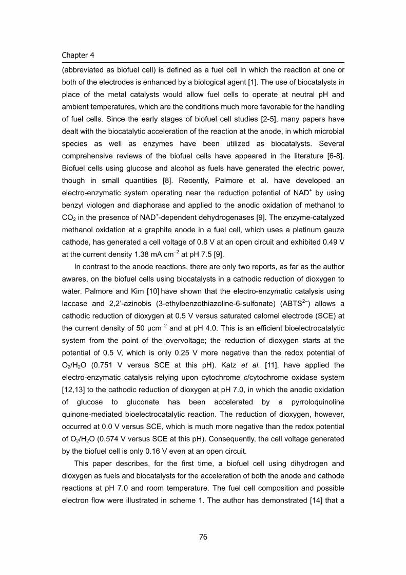
Chapter 4
(abbreviated as biofuel cell) is defined as a fuel cell in which the reaction at one or both of the electrodes is enhanced by a biological agent [1]. The use of biocatalysts in place of the metal catalysts would allow fuel cells to operate at neutral pH and ambient temperatures, which are the conditions much more favorable for the handling of fuel cells. Since the early stages of biofuel cell studies [2-5], many papers have dealt with the biocatalytic acceleration of the reaction at the anode, in which microbial species as well as enzymes have been utilized as biocatalysts. Several comprehensive reviews of the biofuel cells have appeared in the literature [6-8]. Biofuel cells using glucose and alcohol as fuels have generated the electric power, though in small quantities [8]. Recently, Palmore et al. have developed an electro-enzymatic system operating near the reduction potential of NAD+ by using benzyl viologen and diaphorase and applied to the anodic oxidation of methanol to CO2 in the presence of NAD+-dependent dehydrogenases [9]. The enzyme-catalyzed methanol oxidation at a graphite anode in a fuel cell, which uses a platinum gauze cathode, has generated a cell voltage of 0.8 V at an open circuit and exhibited 0.49 V at the current density 1.38 mA cm–2 at pH 7.5 [9].
In contrast to the anode reactions, there are only two reports, as far as the author awares, on the biofuel cells using biocatalysts in a cathodic reduction of dioxygen to water. Palmore and Kim [10] have shown that the electro-enzymatic catalysis using laccase and 2,2’-azinobis (3-ethylbenzothiazoline-6-sulfonate) (ABTS2–) allows a cathodic reduction of dioxygen at 0.5 V versus saturated calomel electrode (SCE) at the current density of 50 μcm–2 and at pH 4.0. This is an efficient bioelectrocatalytic system from the point of the overvoltage; the reduction of dioxygen starts at the potential of 0.5 V, which is only 0.25 V more negative than the redox potential of O2/H2O (0.751 V versus SCE at this pH). Katz et al. [11]. have applied the electro-enzymatic catalysis relying upon cytochrome c/cytochrome oxidase system [12,13] to the cathodic reduction of dioxygen at pH 7.0, in which the anodic oxidation of glucose to gluconate has been accelerated by a pyrroloquinoline quinone-mediated bioelectrocatalytic reaction. The reduction of dioxygen, however, occurred at 0.0 V versus SCE, which is much more negative than the redox potential of O2/H2O (0.574 V versus SCE at this pH). Consequently, the cell voltage generated by the biofuel cell is only 0.16 V even at an open circuit.
This paper describes, for the first time, a biofuel cell using dihydrogen and dioxygen as fuels and biocatalysts for the acceleration of both the anode and cathode reactions at pH 7.0 and room temperature. The fuel cell composition and possible electron flow were illustrated in scheme 1. The author has demonstrated [14] that a
76
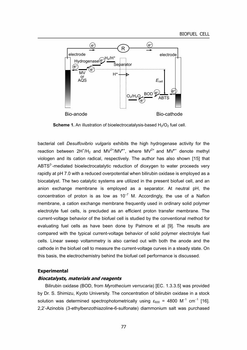
BIOFUEL CELL
BODABTSO2/H2O
H2/H+
MVor
AQS
Separator
e-
e-
e-
e-
e-e-
electrode electrode
Ecell
e-e-
Bio-anode Bio-cathode
H+
R
Hydrogenase
Scheme 1. An illustration of bioelectrocatalysis-based H2/O2 fuel cell.
bacterial cell Desulfovibrio vulgaris exhibits the high hydrogenase activity for the
reaction between 2H+/H2 and MV2+/MV•+, where MV2+ and MV•+ denote methyl viologen and its cation radical, respectively. The author has also shown [15] that ABTS2--mediated bioelectrocatalytic reduction of dioxygen to water proceeds very rapidly at pH 7.0 with a reduced overpotential when bilirubin oxidase is employed as a biocatalyst. The two catalytic systems are utilized in the present biofuel cell, and an anion exchange membrane is employed as a separator. At neutral pH, the concentration of proton is as low as 10–7 M. Accordingly, the use of a Nafion membrane, a cation exchange membrane frequently used in ordinary solid polymer electrolyte fuel cells, is precluded as an efficient proton transfer membrane. The current-voltage behavior of the biofuel cell is studied by the conventional method for evaluating fuel cells as have been done by Palmore et al [9]. The results are compared with the typical current-voltage behavior of solid polymer electrolyte fuel cells. Linear sweep voltammetry is also carried out with both the anode and the cathode in the biofuel cell to measure the current-voltage curves in a steady state. On this basis, the electrochemistry behind the biofuel cell performance is discussed.
Experimental
Biocatalysts, materials and reagents Bilirubin oxidase (BOD, from Myrothecium verrucaria) [EC. 1.3.3.5] was provided
by Dr. S. Shimizu, Kyoto University. The concentration of bilirubin oxidase in a stock
solution was determined spectrophotometrically using ε600 = 4800 M−1 cm−1 [16]. 2,2’-Azinobis (3-ethylbenzothiazoline-6-sulfonate) diammonium salt was purchased
77
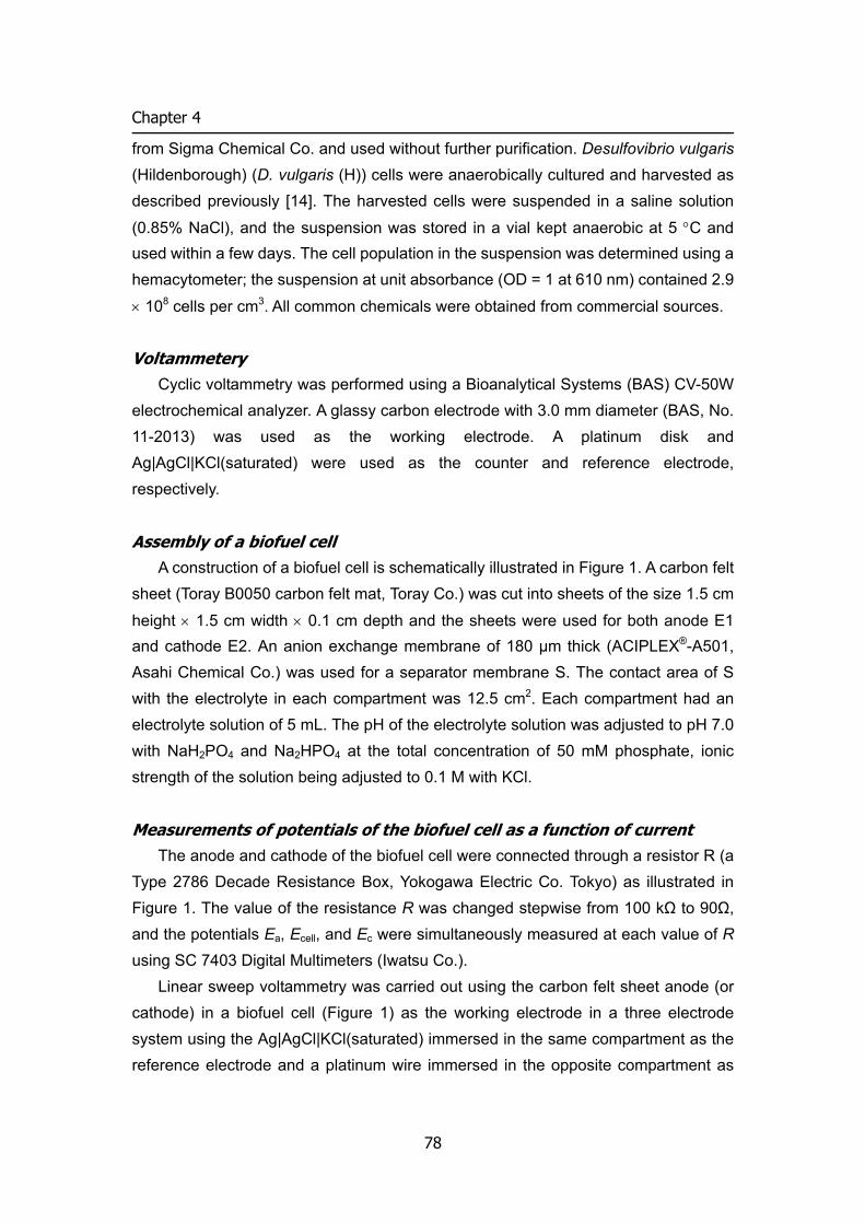
Chapter 4
from Sigma Chemical Co. and used without further purification. Desulfovibrio vulgaris (Hildenborough) (D. vulgaris (H)) cells were anaerobically cultured and harvested as described previously [14]. The harvested cells were suspended in a saline solution
(0.85% NaCl), and the suspension was stored in a vial kept anaerobic at 5 °C and used within a few days. The cell population in the suspension was determined using a hemacytometer; the suspension at unit absorbance (OD = 1 at 610 nm) contained 2.9
× 108 cells per cm3. All common chemicals were obtained from commercial sources.
Voltammetery Cyclic voltammetry was performed using a Bioanalytical Systems (BAS) CV-50W
electrochemical analyzer. A glassy carbon electrode with 3.0 mm diameter (BAS, No. 11-2013) was used as the working electrode. A platinum disk and Ag|AgCl|KCl(saturated) were used as the counter and reference electrode, respectively.
Assembly of a biofuel cell A construction of a biofuel cell is schematically illustrated in Figure 1. A carbon felt
sheet (Toray B0050 carbon felt mat, Toray Co.) was cut into sheets of the size 1.5 cm
height × 1.5 cm width × 0.1 cm depth and the sheets were used for both anode E1 and cathode E2. An anion exchange membrane of 180 μm thick (ACIPLEX®-A501, Asahi Chemical Co.) was used for a separator membrane S. The contact area of S with the electrolyte in each compartment was 12.5 cm2. Each compartment had an electrolyte solution of 5 mL. The pH of the electrolyte solution was adjusted to pH 7.0 with NaH2PO4 and Na2HPO4 at the total concentration of 50 mM phosphate, ionic strength of the solution being adjusted to 0.1 M with KCl.
Measurements of potentials of the biofuel cell as a function of current The anode and cathode of the biofuel cell were connected through a resistor R (a
Type 2786 Decade Resistance Box, Yokogawa Electric Co. Tokyo) as illustrated in Figure 1. The value of the resistance R was changed stepwise from 100 kΩ to 90Ω, and the potentials Ea, Ecell, and Ec were simultaneously measured at each value of R using SC 7403 Digital Multimeters (Iwatsu Co.).
Linear sweep voltammetry was carried out using the carbon felt sheet anode (or cathode) in a biofuel cell (Figure 1) as the working electrode in a three electrode system using the Ag|AgCl|KCl(saturated) immersed in the same compartment as the reference electrode and a platinum wire immersed in the opposite compartment as
78
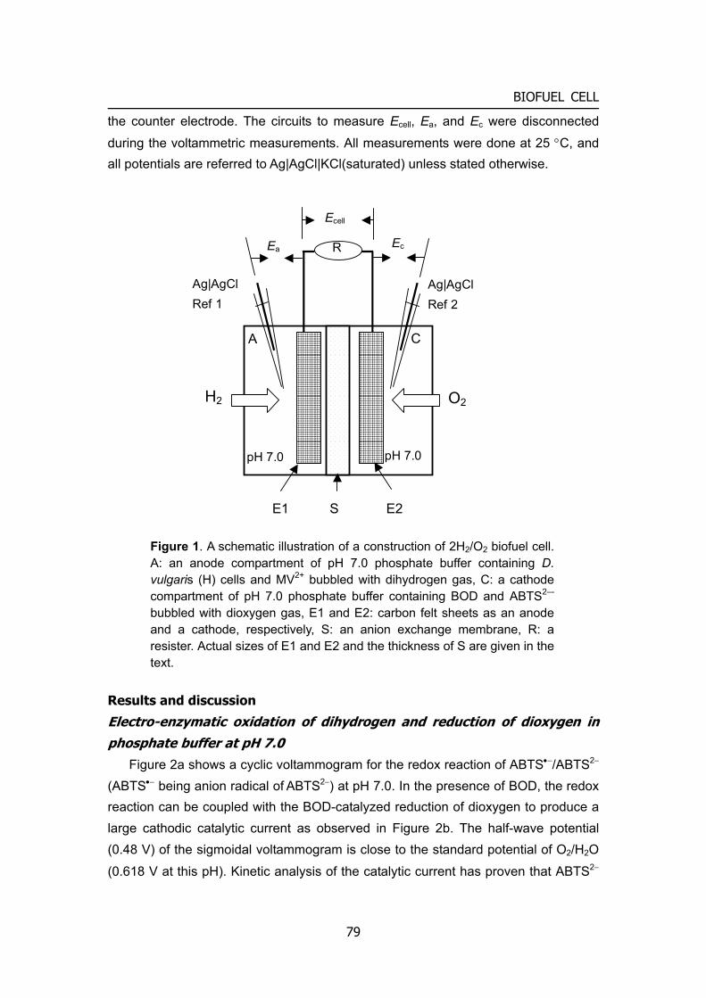
BIOFUEL CELL
the counter electrode. The circuits to measure Ecell, Ea, and Ec were disconnected
during the voltammetric measurements. All measurements were done at 25 °C, and all potentials are referred to Ag|AgCl|KCl(saturated) unless stated otherwise.
Results and discussion
Electro-enzymatic oxidation of dihydrogen and reduction of dioxygen in phosphate buffer at pH 7.0
Figure 2a shows a cyclic voltammogram for the redox reaction of ABTS•−/ABTS2− (ABTS•− being anion radical of ABTS2−) at pH 7.0. In the presence of BOD, the redox reaction can be coupled with the BOD-catalyzed reduction of dioxygen to produce a large cathodic catalytic current as observed in Figure 2b. The half-wave potential (0.48 V) of the sigmoidal voltammogram is close to the standard potential of O2/H2O
(0.618 V at this pH). Kinetic analysis of the catalytic current has proven that ABTS2−
R
Ecell
H2 O2
Ec Ea
Ag|AgCl Ref 1
pH 7.0 pH 7.0
Ag|AgCl Ref 2
E1 S E2
A C
Figure 1. A schematic illustration of a construction of 2H2/O2 biofuel cell. A: an anode compartment of pH 7.0 phosphate buffer containing D. vulgaris (H) cells and MV2+ bubbled with dihydrogen gas, C: a cathode compartment of pH 7.0 phosphate buffer containing BOD and ABTS2–- bubbled with dioxygen gas, E1 and E2: carbon felt sheets as an anode and a cathode, respectively, S: an anion exchange membrane, R: a resister. Actual sizes of E1 and E2 and the thickness of S are given in the text.
79
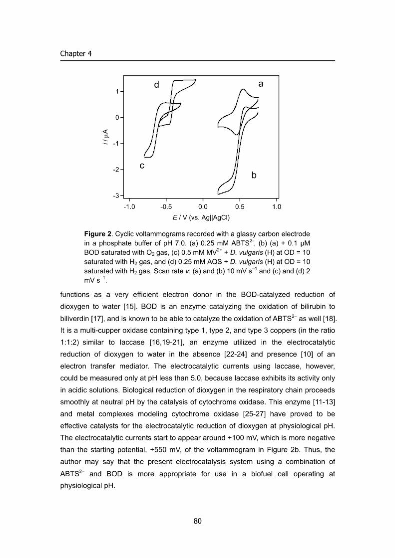
Chapter 4
-3
-2
-1
0
1
i / μ
A
-1.0 -0.5 0.0 0.5 1.0E / V (vs. Ag||AgCl)
a
bc
d
Figure 2. Cyclic voltammograms recorded with a glassy carbon electrode in a phosphate buffer of pH 7.0. (a) 0.25 mM ABTS2-, (b) (a) + 0.1 μM BOD saturated with O2 gas, (c) 0.5 mM MV2+ + D. vulgaris (H) at OD = 10 saturated with H2 gas, and (d) 0.25 mM AQS + D. vulgaris (H) at OD = 10 saturated with H2 gas. Scan rate v: (a) and (b) 10 mV s–1 and (c) and (d) 2 mV s–1.
functions as a very efficient electron donor in the BOD-catalyzed reduction of dioxygen to water [15]. BOD is an enzyme catalyzing the oxidation of bilirubin to
biliverdin [17], and is known to be able to catalyze the oxidation of ABTS2− as well [18]. It is a multi-cupper oxidase containing type 1, type 2, and type 3 coppers (in the ratio 1:1:2) similar to laccase [16,19-21], an enzyme utilized in the electrocatalytic reduction of dioxygen to water in the absence [22-24] and presence [10] of an electron transfer mediator. The electrocatalytic currents using laccase, however, could be measured only at pH less than 5.0, because laccase exhibits its activity only in acidic solutions. Biological reduction of dioxygen in the respiratory chain proceeds smoothly at neutral pH by the catalysis of cytochrome oxidase. This enzyme [11-13] and metal complexes modeling cytochrome oxidase [25-27] have proved to be effective catalysts for the electrocatalytic reduction of dioxygen at physiological pH. The electrocatalytic currents start to appear around +100 mV, which is more negative than the starting potential, +550 mV, of the voltammogram in Figure 2b. Thus, the author may say that the present electrocatalysis system using a combination of
ABTS2− and BOD is more appropriate for use in a biofuel cell operating at physiological pH.
80
BIOFUEL CELL
Figure 2c shows a cyclic voltammogram for methyl viologen-mediated D. vulgaris (H) cell-catalyzed redox reaction of 2H+/H2. It is noted that the sigmoidal cyclic voltammogram has both cathodic and anodic limiting currents with the half-wave potential (–0.635 V, the average of the potentials obtained from the negative-going and positive-going voltammograms) in agreeing with the mid-potential Em (–0.634 V, the potential at the mid point between the anodic and cathodic peaks) of the cyclic
voltammogram for the redox reaction of MV2+/MV•+ (data not shown). This means that the methyl viologen-mediated electrocatalysis is voltammetrically reversible as has been discussed previously [14], that is, the electrocatalytic system allows both the oxidation of dihydrogen and the reduction of proton depending on the potential applied to the electrode. The anodic current for the oxidation of dihydrogen starts to appear from –0.61 V (the null potential obtained as the average of those on the negative-going and positive-going voltammograms in Figure 2c), which agrees with the standard potential of 2H+/H2 (–0.611 V at pH 7.0). Figure 2d is the voltammogram obtained with anthraquinone 2-sulfonate (AQS). AQS has Em of –0.42 V at pH 7.0, a potential more positive than the standard potential of 2H+/H2. This favors the direction of dihydrogen oxidation, accordingly only an anodic limiting current is observed, and the magnitude is larger than that observed with methyl viologen [14, 28].
The catalytic activity of D. vulgaris (H) is due to hydrogenase existing in the periplasmic space behind the outer membrane of the bacterial cell [14, 28]. Catalysis of isolated hydrogenases has been studied for the oxidation of dihydrogen using the natural electron acceptors, cytochrome c3 [29-31] and cytochrome c553 [32], and catalytic currents of significant magnitude have been reported for the cytochromes c-mediated oxidation of dihydrogen [29-31]. Hydrogenases isolated from Thiocapsa roseopersina [33] and Megasphaera elsdenii [34] allowed direct electrocatalysis without a mediator, producing a voltammogram with both anodic and cathodic currents. The anodic current for the oxidation of dihydrogen starts from –0.61 V, and has the limiting current smaller than the cathodic limiting current [34], which is very similar to our result in Figure 2c. The results indicate that D. vulgaris (H) exhibits catalytic activity as high as the isolated hydrogenases. This is a fortunate result, since whole cells of D. vulgaris (H) are more stable and easier to handle than isolated hydrogenases.
81
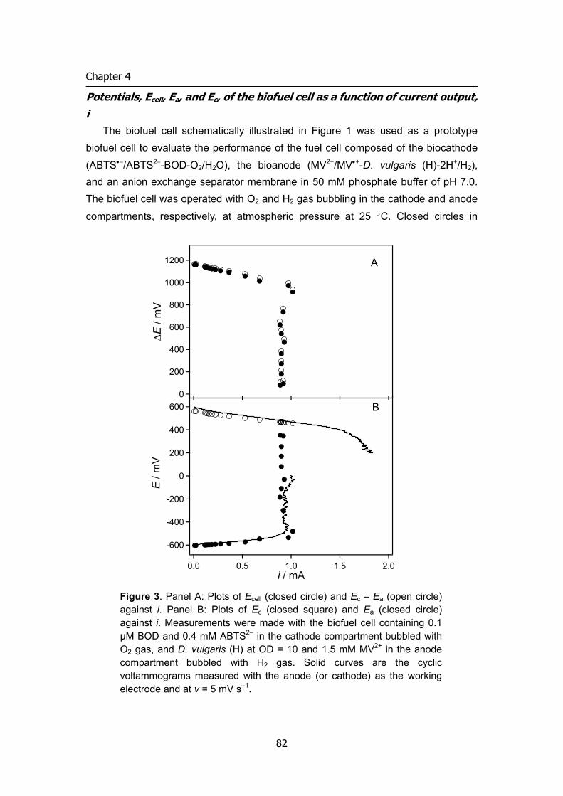
Chapter 4
Potentials, Ecell, Ea, and Ec, of the biofuel cell as a function of current output, i
The biofuel cell schematically illustrated in Figure 1 was used as a prototype biofuel cell to evaluate the performance of the fuel cell composed of the biocathode
(ABTS•−/ABTS2−-BOD-O2/H2O), the bioanode (MV2+/MV•+-D. vulgaris (H)-2H+/H2), and an anion exchange separator membrane in 50 mM phosphate buffer of pH 7.0. The biofuel cell was operated with O2 and H2 gas bubbling in the cathode and anode
compartments, respectively, at atmospheric pressure at 25 °C. Closed circles in
600
400
200
0
-200
-400
-600
E /
mV
2.01.51.00.50.0i / mA
B
1200
1000
800
600
400
200
0
ΔE
/ mV
A
Figure 3. Panel A: Plots of Ecell (closed circle) and Ec – Ea (open circle) against i. Panel B: Plots of Ec (closed square) and Ea (closed circle) against i. Measurements were made with the biofuel cell containing 0.1 μM BOD and 0.4 mM ABTS2− in the cathode compartment bubbled with O2 gas, and D. vulgaris (H) at OD = 10 and 1.5 mM MV2+ in the anode compartment bubbled with H2 gas. Solid curves are the cyclic voltammograms measured with the anode (or cathode) as the working electrode and at v = 5 mV s–1.
82
BIOFUEL CELL
Figure 3A plot Ecell against i, where i was calculated from the Ecell value at a given value of R. A constant value of Ecell, which was attained a few seconds after fixing R at a given value, was recorded for about 30 s at each value of R. It was confirmed that the Ecell values were reproducible in repetitive measurements over one hour period. The Ecell value is 1.17 V at an open circuit, which is close to the standard
electromotive force (1.23 V) for the reaction H2 + 1/2O2 → H2O, and remains 1.0 V at the current flowing at i = 0.9 mA. This is a significant result in view of that it is even larger than the value of the cell voltage (1.0 V) realized in solid polymer electrolyte
fuel cells at an open circuit at 50 °C and 1 atm pressure [35]. The value of Ecell, however, begins to decrease rapidly down to zero at around i = 1 mA (this leads to 0.2 mA cm-2 for the current density at the felt electrode calculated per projected surface area), which is much smaller than the current attained in the solid polymer electrolyte
fuel cells, 0.2 A cm−2 or more [35]. The author will later discuss the factor determining the upper limit of i of the biofuel cell.
Open circles in Figure 3A plot the quantity Ec – Ea against i. Each open circle is located only slightly above the closed circle (Ecell) at the corresponding value of i. The small difference between Ec – Ea and Ecell assures that the internal resistance of the biofuel cell is small, that is, the anion exchange membrane works well as a separator. The primary ionic species carrying charges through the anion exchange membrane
are HPO42− and H2PO4
−. The biofuel cell reactions generate protons in the anode reaction and consume them in the cathode reaction. The generation and consumption
of protons causes the change in the concentration ratio of HPO42− to H2PO4
−, [HPO4
2−]/[H2PO4−]; the ratio decreases in the anode compartment and increases in
the cathode compartment. Accordingly, H2PO4− (HPO4
2−) moves from the anode (cathode) to the cathode (anode) through the anion exchange membrane. The net
charge transfer process will involve the proton transfer reaction between HPO42− and
H2PO4−, which is known to be a very rapid reaction. In this way, the pH of the anode
and cathode compartments can be kept constant during the flow of the current. It should be noted, however, that above discussion assumes ideal behavior of the anion exchange membrane. Actual ion transfer mechanism would be more complicated one; there are possibilities of leakage of other ionic species such as the mediator
compound ABTS•−/ABTS2− and protons, higher concentrations of phosphate species inside of the membrane, and permeation of dioxygen and dihydrogen gas through the membrane. They may affect the actual performance of the biofuel cell and cause time-dependent deterioration of the biofuel cell. The author has preliminary confirmed that the current produced by the biofuel cell remains unchanged in the magnitude at
83
Chapter 4
least for 2 h when measured with R = 700Ω. Study of the lifetime of the biofuel cell will be our next project.
Figure 3B shows the dependence of Ec (closed square) and Ea (closed circle) on i. Solid curves in the figure depict linear sweep voltammograms recorded on a three electrode system as described in the Experimental section with the cathode or the anode in the biofuel cell system as the working electrode. The voltammograms are essentially the same in shape as the cyclic voltammograms obtained with a glassy carbon electrode (Figures 2b and 2c) and are superimposable on the plots of Ec (closed square) and Ea (closed circle) against i. The sigmoidal shape of the voltammograms reflects that the electro-enzymatic reactions at the felt electrodes are in a steady state. The voltammogram recorded with the anode exactly traces the Ea versus i plot at i > 0, and the voltammogram with the cathode traces the Ec versus i plot but increases further to reach a limiting current. The result reveals that the maximum current obtained with the biofuel cell is limited by the anodic reaction. The agreement of the voltammograms with the Ec (and Ea) versus i plots is not surprising, since a given electrochemical system should give the same current-potential curve independent of the method of the electrochemical measurement in a steady state. Nevertheless, this is a significant observation demonstrating that conventional voltammetry provides a convenient method of analyzing the dependence of the cell voltage on the output current of a biofuel cell. Figure 4 shows Ec (square) (and Ea (circle)) versus i plots obtained with the biofuel cell using AQS as a mediator in the anode reaction. A larger maximum current is obtained compared with that in Figure 3 as expected from the cyclic voltammogram in Figure 2d. The maximum current is, in this case, controlled by the rate of the cathode reaction, and is dependent on the concentrations of BOD (Figures 4 A and B). Factors influencing the maximum current for a mediated electro-enzymatic reaction have been quantitatively studied using carbon felt electrodes by linear sweep voltammetry and chronoamperometry [36]. The current density per projected surface area at a felt electrode depends on the structure of the carbon felt [36]. When the carbon felt used in the present study (the average distance between the fibers, l, is 170 μm [36]) is replaced with, for example, carbon felt with l =17 μm, it is expected that the current density per projected surface area will be increased in two orders of magnitude.
84
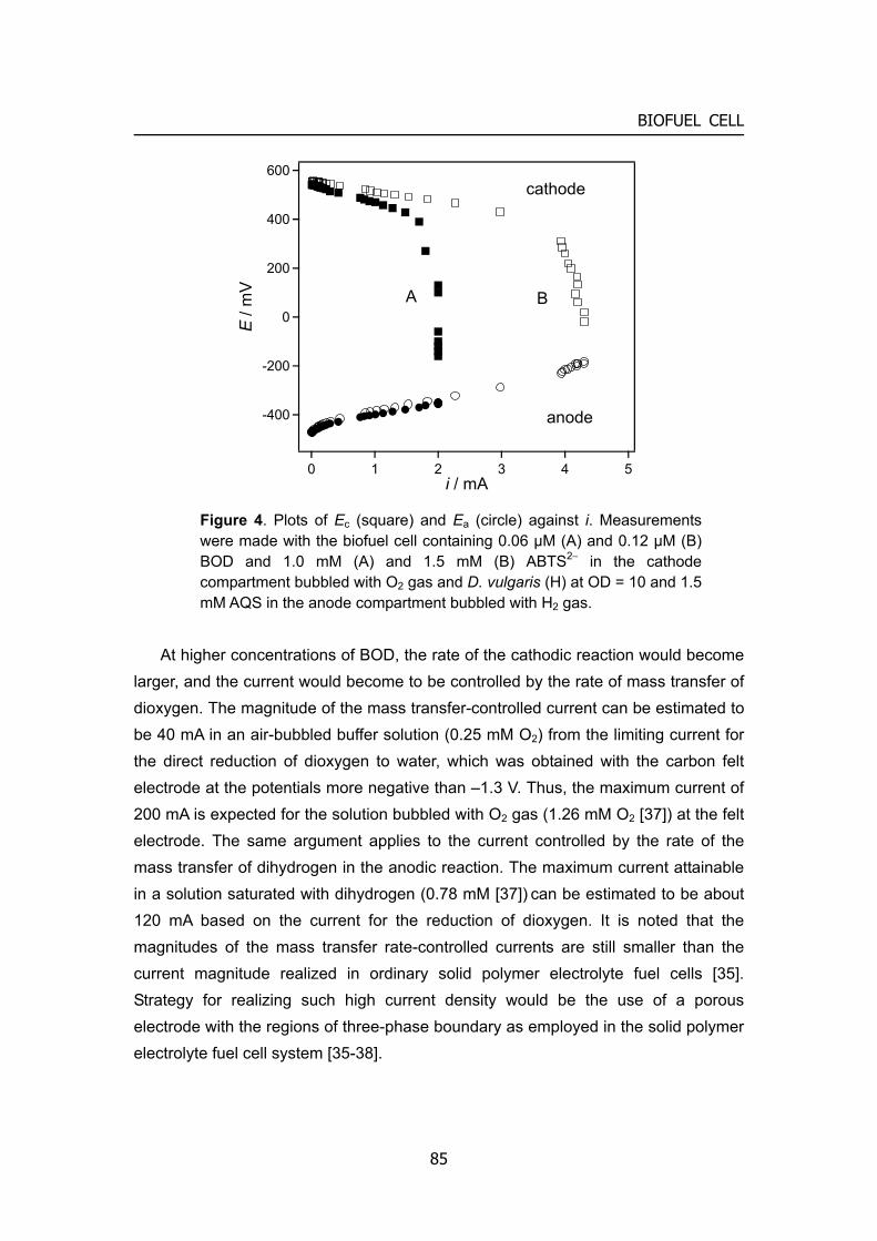
BIOFUEL CELL
600
400
200
0
-200
-400
E /
mV
543210i / mA
cathode
anode
A B
Figure 4. Plots of Ec (square) and Ea (circle) against i. Measurements were made with the biofuel cell containing 0.06 μM (A) and 0.12 μM (B) BOD and 1.0 mM (A) and 1.5 mM (B) ABTS2− in the cathode compartment bubbled with O2 gas and D. vulgaris (H) at OD = 10 and 1.5 mM AQS in the anode compartment bubbled with H2 gas.
At higher concentrations of BOD, the rate of the cathodic reaction would become larger, and the current would become to be controlled by the rate of mass transfer of dioxygen. The magnitude of the mass transfer-controlled current can be estimated to be 40 mA in an air-bubbled buffer solution (0.25 mM O2) from the limiting current for the direct reduction of dioxygen to water, which was obtained with the carbon felt electrode at the potentials more negative than –1.3 V. Thus, the maximum current of 200 mA is expected for the solution bubbled with O2 gas (1.26 mM O2 [37]) at the felt electrode. The same argument applies to the current controlled by the rate of the mass transfer of dihydrogen in the anodic reaction. The maximum current attainable in a solution saturated with dihydrogen (0.78 mM [37]) can be estimated to be about 120 mA based on the current for the reduction of dioxygen. It is noted that the magnitudes of the mass transfer rate-controlled currents are still smaller than the current magnitude realized in ordinary solid polymer electrolyte fuel cells [35]. Strategy for realizing such high current density would be the use of a porous electrode with the regions of three-phase boundary as employed in the solid polymer electrolyte fuel cell system [35-38].
85
Chapter 4
In conclusion, the author has demonstrated that a combination of efficient bioelectrocatalytic systems for the oxidation of dihydrogen and the reduction of dioxygen with an anion exchange membrane allows a biofuel cell to operate at neutral pH and ambient temperature with the cell potential close to the standard
electromotive force at an open circuit for the reaction 2H2 + O2 → 2H2O. The current-potential behavior at each electrode during the operation can be characterized by linear sweep voltammetry recorded with the same electrode system. Factors governing the maximum current density have been discussed. Next direction of biofuel cell research will be the study of the chemistry governing the lifetime of the present type of biofuel cell, then realization of the biofuel cell with high current density and long lifetime.
References
[1] T. G. Young, L. Hadjipetrou, and M. D. Lilly, Biotech. Bioeng., 8, 581 (1966). [2] M. C. Potter, Proc. Roy. Soc. London, Ser. B., 84, 260 (1911). [3] B. Cohen, J. Bacteriol., 21, 18 (1931). [4] J. B. Davis and H. F. Yarbrough, Jr., Science, 137, 615 (1962). [5] J. Mizuguchi, S. Suzuki, F. Takahashi, and K. Kashiya, Kogyo Kagaku Zasshi (in
Jananese), 65, 1606 (1962). [6] L. B. Wingard, Jr, C. H. Shaw, and J. F. Castner, Enzyme. Microbiol. Technol., 4,
137 (1982). [7] G. Davis, H. A. O. Hill, W. J. Aston, I. J. Higgins, and A. P. F. Turner, Enzyme.
Microbiol. Technol., 5, 382 (1983). [8] G. T. R. Palmore and G. M. Whitesides, ACS Symp. Series No.556, 271 (1994). [9] G. T. R. Palmore, H. Bertschy, S. H. Bergens, and G. M. Whitesides, J. Electroanal.
Chem., 443, 155 (1998). [10] G. T. R. Palmore and H-H. Kim, J. Electroanal. Chem., 464, 110 (1999). [11] E. Katz, I. Willner, and A. B. Kotlyar, J. Electroanal. Chem., 479, 64 (1999). [12] H. A. O. Hill, N. J. Walton, and I. J. Higgins, FEBS Lett., 126, 282 (1981). [13] H. A. O. Hill and N. J. Walton, J. Am. Chem. Soc., 104, 6515 (1982). [14] H. Tatsumi, K. Takagi, M. Fujita, K. Kano, and T. Ikeda, Anal. Chem., 71, 1753
(1999). [15] S. Tsujimura, H. Tatsumi, J. Ogawa, S. Shimizu, K. Kano, and T. Ikeda, J.
Electroanal. Chem., 496, 69 (2000). [16] A. Shimizu, J-H. Kwon, T. Sasaki, T. Satoh, N. Sakurai, T. Sakurai, T. Yamaguchi,
and T. Samejima, J. Biochem., 125, 662 (1999).
86
BIOFUEL CELL
[17] S. Murao and N. Tanaka, Agric. Biol. Chem., 46, 2031 (1982). [18] F. Xu, W. Shin, S. H. Brown, J. A. Wahleithner, U. M. Sundaram, and E. I.
Solomon, Biochim. Biophys. Acta, 1292, 303 (1996). [19] N. Tanaka and S. Murao, Agric. Biol. Chem., 46, 2499 (1982). [20] Y. Gotoh, Y. Kondo, H. Kaji, A. Takeda, and T. Samejima, J. Biochem., 106, 621
(1989). [21] A. Shimizu, J-H. Kwon, T. Sasaki, T. Satoh, N. Sakurai, T. Sakurai, S. Yamaguchi,
and T. Samejima, Biochemistry, 38, 3034 (1999). [22] M. R. Tarasevich, A. I. Yaropolov, V. A. Bogdanovskaya, and S. D. Varfolomeyev,
Bioelectrochem. Bioenerg., 6, 393 (1979). [23] C-W. Lee, H. B. Gray, F. C. Anson and B. G. Malmstrom, J. Electroanal. Chem.,
172, 289 (1984). [24] A. I. Yaropolov, A. N. Kharybin, J. Emneus, G. Marko-Varga, and L. Gorton,
Bioelectrochem. Bioenerg., 40, 49 (1996). [25] J. P. Collman, L. Fu, P. C. Hermann, and X. Zhang, Science, 275, 949 (1997). [26] J. P. Collman, L. Fu, P. C. Hermann, Z. Wang, M. Rapta, M. Broring, R.
Schwenninger, and B. Boitrel, Angew. Chem. Int. Ed., 37, 3397 (1998). [27] J. P. Collman, M. Rapta, M. Broring, L. Raptove, R. Schwenninger, B. Boitrel, L.
Fu, and M. L’Her, J. Am. Chem. Soc., 121, 1387 (1999). [28] H. Tatsumi, K. Kano, and T. Ikeda, J. Phys. Chem. B, 104, 12079 (2000). [29] J. Haladjian, P. Bianco, F. Guerlesquin, and M. Bruschi, Biochem. Biophys. Res.
Commun., 147, 1289 (1987). [30] V. Niviere, E. C. Hatchikan, P. Bianco, and J. Haladjian, Biochim. Biophys. Acta,
935, 34 (1988). [31] P. Bianco, J. Haladjian, M. Bruschi, and F. Guerlesquin, Biochem. Biophys. Res.
Commun., 189, 633 (1992). [32] M. F. J. Verhagen, R. B. G. Wolbert, and W. R. Hagen, Eur. J. Biochem., 221, 821
(1994). [33] S. D. Varfolomeyev, A. I. Yaropolov, and A. A. Karyakin, J. Biotech., 27, 331
(1993). [34] J. N. Butt, M. Eilipiak, and W. R. Hagen, Eur. J. Biochem., 245, 116 (1997). [35] S. Srinivasan, O. A. Velev, A. Parthasarathy, D. J. Manko and A. J. Appleby, J.
Power Sources, 36, 299 (1991). [36] K. Kato, K. Kano, and T. Ikeda, J. Electrochem. Soc., 147, 1449 (2000). [37] Handbook of Chemistry II, ed. Chemical Soc. Jpn., Maruzen, Tokyo, p.158
(1984).
87
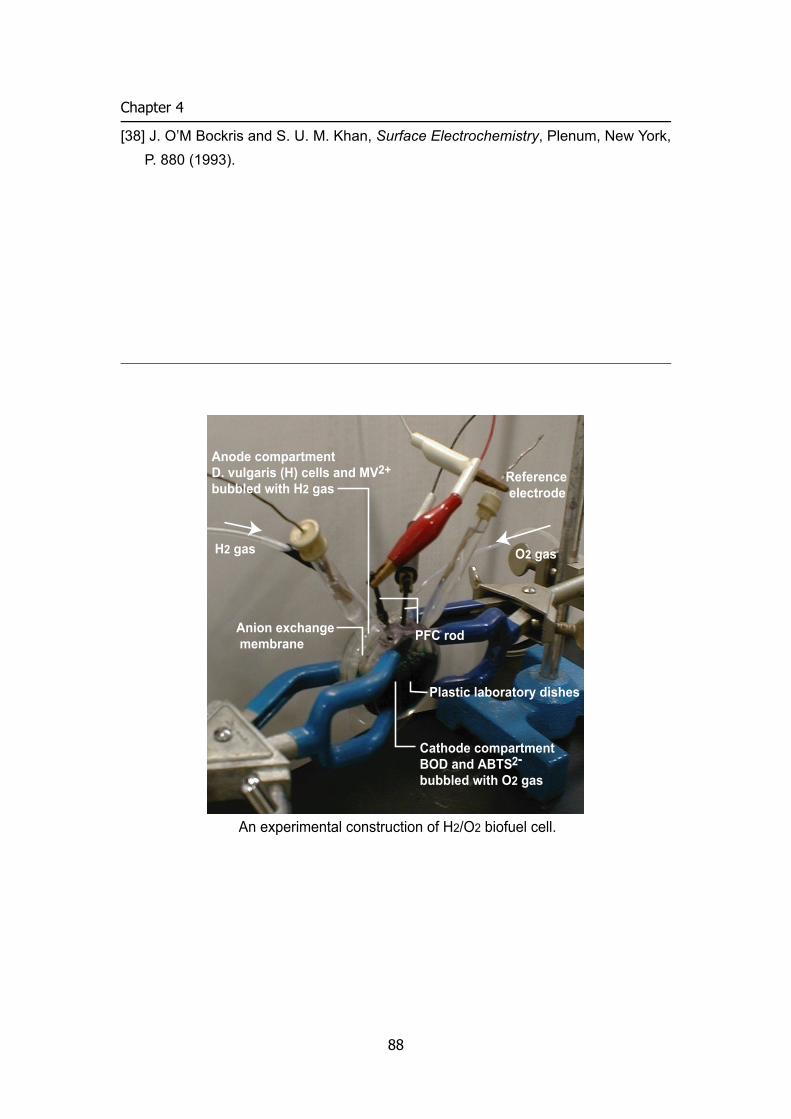
Chapter 4
[38] J. O’M Bockris and S. U. M. Khan, Surface Electrochemistry, Plenum, New York, P. 880 (1993).
An experimental construction of H2/O2 biofuel cell.
Anode compartmentD. vulgaris (H) cells and MV2+bubbled with H2 gas
Reference electrode
H2 gas O2 gas
Cathode compartmentBOD and ABTS2-bubbled with O2 gas
Anion exchange membrane PFC rod
Plastic laboratory dishes
88
BIOFUEL CELL
Photosynthetic bioelectrochemical cell utilizing cyanobacteria and water-generating oxidase 2
A novel photosynthetic bioelectrochemical cell that utilizes biocatalysts in both anode
and cathode compartments was constructed for the first time. In the anodic half-cell,
some parts of the electrons produced by the oxidation of water in the photosystem of
cyanobacteria are transferred to the carbon felt anode through quinonoid electron
transfer mediators. The electron is passed to dioxygen to regenerate water in the
cathodic half-cell reaction with an aid of bilirubin oxidase reaction via a mediator. The
maximum electric power was about 0.3−0.4 W m–2 for the projective electrode surface
area at an apparent efficiency of the light energy conversion of 2−2.5%. The factors
governing the cell output are discussed on the basis of the potential-current curves of
each half-cell.
Introduction
Photo-electrochemical cells (or batteries) have been investigated as devices converting the light energy into the electric energy. Solar cells using semi-conductors have been come into practical use. Dye-sensitized solar cells also draw attention for its high efficiency and facility [1], for which several organic compounds or metal complexes have been investigated as photo-sensitizers. Biological photosystem may be also utilized as photo-electrochemical cells [2].
The high-energy electrons produced by the light excitation in the photosystem can be transferred to electrodes through suitable exogenous electron transfer mediators (Scheme 1). For this purpose, several voltammetric studies have been done to investigate photo-bioelectrochemical anodic reactions using chloroplast [3-7], photosystems I [8] and II [9-11], and thylakoid membranes [12-13]. Intact microorganisms, such as cyanobacteria, have been also used as a photosynthetic system [14-15]. Advantages of the use of intact whole cells are that any special isolation process is not required and that its high stability of the photosystem can be expected. In photo-bioelectrochemical anodic reaction involving photosystem II, the overall reaction is photosystem-catalyzed electrochemical oxidation of water to dioxygen. Carbohydrates produced in the dark reaction of the photosynthetic system can also be oxidized electrochemically by using suitable exogenous electron transfer mediators [15-17]. Prototypes of photosynthetic bioelectrochemical cells were reported in the literature by utilizing such photosynthetic systems [15-17, 19].
89
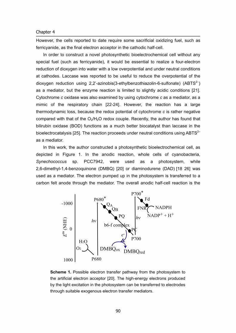
Chapter 4
However, the cells reported to date require some sacrificial oxidizing fuel, such as ferricyanide, as the final electron acceptor in the cathodic half-cell.
In order to construct a novel photosynthetic bioelectrochemical cell without any special fuel (such as ferricyanide), it would be essential to realize a four-electron reduction of dioxygen into water with a low overpotential and under neutral conditions at cathodes. Laccase was reported to be useful to reduce the overpotential of the
dioxygen reduction using 2,2’-azinobis(3-ethylbenzothiazolin-6-sulfonate) (ABTS2−) as a mediator, but the enzyme reaction is limited to slightly acidic conditions [21]. Cytochrome c oxidase was also examined by using cytochrome c as a mediator, as a mimic of the respiratory chain [22-24]. However, the reaction has a large thermodynamic loss, because the redox potential of cytochrome c is rather negative compared with that of the O2/H2O redox couple. Recently, the author has found that bilirubin oxidase (BOD) functions as a much better biocatalyst than laccase in the bioelectrocatalysis [25]. The reaction proceeds under neutral conditions using ABTS2– as a mediator.
In this work, the author constructed a photosynthetic bioelectrochemical cell, as depicted in Figure 1. In the anodic reaction, whole cells of cyanobacteria, Synechococcus sp. PCC7942, were used as a photosystem, while 2,6-dimethyl-1,4-benzoquinone (DMBQ) [20] or diaminodurene (DAD) [18 26] was used as a mediator. The electron pumped up in the photosystem is transferred to a carbon felt anode through the mediator. The overall anodic half-cell reaction is the
P680*P700*
P700
P680
H2OO2
NADP+ + H+NADPH
-1000
0
1000
E0 ' (NH
E) hνhν
QAQB
PQ
b6-f complexPC
Fd
FNR
DMBQox DMBQred
e-
Scheme 1. Possible electron transfer pathway from the photosystem to the artificial electron acceptor [20]. The high-energy electrons produced by the light excitation in the photosystem can be transferred to electrodes through suitable exogenous electron transfer mediators.
90
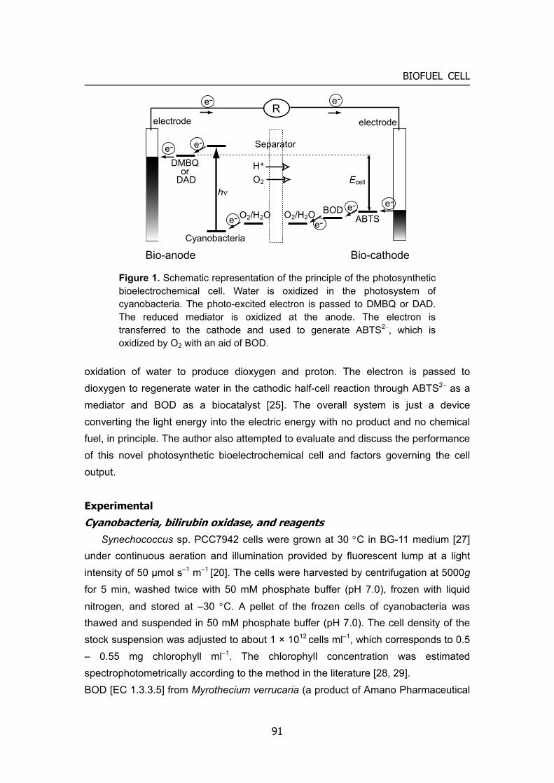
BIOFUEL CELL
hν
Cyanobacteria
BODABTSO2/H2OO2/H2O
DMBQor
DAD
Separator
e-
e-
e-
e-
e-e-
electrode electrode
Ecell
e-e-
Bio-anode Bio-cathode
H+
O2
R
Figure 1. Schematic representation of the principle of the photosynthetic bioelectrochemical cell. Water is oxidized in the photosystem of cyanobacteria. The photo-excited electron is passed to DMBQ or DAD. The reduced mediator is oxidized at the anode. The electron is transferred to the cathode and used to generate ABTS2−, which is oxidized by O2 with an aid of BOD.
oxidation of water to produce dioxygen and proton. The electron is passed to dioxygen to regenerate water in the cathodic half-cell reaction through ABTS2– as a mediator and BOD as a biocatalyst [25]. The overall system is just a device converting the light energy into the electric energy with no product and no chemical fuel, in principle. The author also attempted to evaluate and discuss the performance of this novel photosynthetic bioelectrochemical cell and factors governing the cell output.
Experimental
Cyanobacteria, bilirubin oxidase, and reagents Synechococcus sp. PCC7942 cells were grown at 30 °C in BG-11 medium [27]
under continuous aeration and illumination provided by fluorescent lump at a light intensity of 50 μmol s–1 m–1 [20]. The cells were harvested by centrifugation at 5000g for 5 min, washed twice with 50 mM phosphate buffer (pH 7.0), frozen with liquid
nitrogen, and stored at –30 °C. A pellet of the frozen cells of cyanobacteria was thawed and suspended in 50 mM phosphate buffer (pH 7.0). The cell density of the stock suspension was adjusted to about 1 × 10¹² cells ml–1, which corresponds to 0.5 – 0.55 mg chlorophyll ml–1. The chlorophyll concentration was estimated spectrophotometrically according to the method in the literature [28, 29]. BOD [EC 1.3.3.5] from Myrothecium verrucaria (a product of Amano Pharmaceutical
91
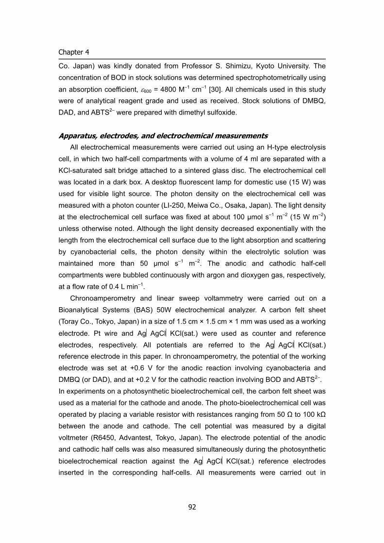
Chapter 4
Co. Japan) was kindly donated from Professor S. Shimizu, Kyoto University. The concentration of BOD in stock solutions was determined spectrophotometrically using
an absorption coefficient, ε600 = 4800 M–1 cm–1 [30]. All chemicals used in this study were of analytical reagent grade and used as received. Stock solutions of DMBQ, DAD, and ABTS2– were prepared with dimethyl sulfoxide.
Apparatus, electrodes, and electrochemical measurements All electrochemical measurements were carried out using an H-type electrolysis
cell, in which two half-cell compartments with a volume of 4 ml are separated with a KCl-saturated salt bridge attached to a sintered glass disc. The electrochemical cell was located in a dark box. A desktop fluorescent lamp for domestic use (15 W) was used for visible light source. The photon density on the electrochemical cell was measured with a photon counter (LI-250, Meiwa Co., Osaka, Japan). The light density at the electrochemical cell surface was fixed at about 100 μmol s–1 m–2 (15 W m–2) unless otherwise noted. Although the light density decreased exponentially with the length from the electrochemical cell surface due to the light absorption and scattering by cyanobacterial cells, the photon density within the electrolytic solution was maintained more than 50 μmol s–1 m–2. The anodic and cathodic half-cell compartments were bubbled continuously with argon and dioxygen gas, respectively, at a flow rate of 0.4 L min–1.
Chronoamperometry and linear sweep voltammetry were carried out on a Bioanalytical Systems (BAS) 50W electrochemical analyzer. A carbon felt sheet (Toray Co., Tokyo, Japan) in a size of 1.5 cm × 1.5 cm × 1 mm was used as a working
electrode. Pt wire and AgAgClKCl(sat.) were used as counter and reference electrodes, respectively. All potentials are referred to the AgAgClKCl(sat.) reference electrode in this paper. In chronoamperometry, the potential of the working electrode was set at +0.6 V for the anodic reaction involving cyanobacteria and DMBQ (or DAD), and at +0.2 V for the cathodic reaction involving BOD and ABTS2–. In experiments on a photosynthetic bioelectrochemical cell, the carbon felt sheet was used as a material for the cathode and anode. The photo-bioelectrochemical cell was operated by placing a variable resistor with resistances ranging from 50 Ω to 100 kΩ between the anode and cathode. The cell potential was measured by a digital voltmeter (R6450, Advantest, Tokyo, Japan). The electrode potential of the anodic and cathodic half cells was also measured simultaneously during the photosynthetic
bioelectrochemical reaction against the AgAgClKCl(sat.) reference electrodes inserted in the corresponding half-cells. All measurements were carried out in
92
BIOFUEL CELL
phosphate buffer of pH 7.0 with an ionic strength of 0.1 (adjusted with KCl) at 25 °C unless stated otherwise.
Results and discussion
Chronoamperometry of the half-cell reactions The cathodic half-cell compartment contains BOD as a biocatalyst and
ABTS2– as a mediator. The reaction is written as follows [25]: −•+− +⎯⎯ →⎯++ 4ABTSO2H4H4ABTSO 2
BOD2
2 (1a) −−• ⎯⎯⎯ →⎯ 2ABTSABTS electrode (1b)
The overall reaction is a bioelectrocatalytic four-electron reduction of dioxygen to water. Linear sweep voltammograms showed a sigmoidal catalytic wave at a carbon felt electrode (data not shown, see also ref. [25]). The presence of BOD, ABTS2–, and dissolved dioxygen was essential to produce such reduction current. The half-wave potential of the catalytic wave (0.49 V) was very close to the formal redox potential
(E°'pH 7) of the ABTS•–/ABTS2– couple (0.505 V) [25]. This is due to highly reversible characteristics of the electrode reaction of ABTS2– [31]. The equilibrium potential
-4
-3
-2
-1
0
i /
mA
20100t / min
12
34
5
6
1.0
0.5
0.0
i s / m
A
6040200[BOD] t / nM
Figure 2. The catalytic reduction current (i) of O2 at a carbon felt electrode observed at +0.2 V and at [BOD]t = 0.11 μM in pH 7.0 phosphate buffer under O2 saturated conditions. ABTS2– was injected at points1−6 at [ABTS2–]t = 0.1, 0.2, 0.3, 0.4, 0.6, and 0.8 mM in turn. The inset shows the steady-state current (Is) as a function of [BOD]t at [ABTS2–]t = 0.25 mM.
93
Chapter 4
(Eeq,c) at open circuit (and at [BOD]t = 0.1 μM, [ABTS2–]t = 0.5 mM) was 0.57 V, which
is close to E°'pH 7 of the O2/H2O couple (0.618 V). Since Eeq,c > E°'pH 7(ABTS•–/ABTS2–), the most of ABTS2– are oxidized in the bulk phase.
Figure 2 shows the cathodic current response at +0.2 V on the successive addition of ABTS2–. The steady-state current (or kinetics) was observed. This is contrastive to usual (non-catalytic) bulk electrolysis with a carbon fiber electrode, which obeys a first-order kinetics under convectional condition because of large electrode surface area to the solution volume [32]. Under the steady-state condition, the electrode reaction is balanced with the enzyme reaction in the reaction layer near the electrode surface. When the convection effect is ignored, the steady-state current (Is) is expressed by [32– 34]
tM
catMMStMs ]M[
]E[)/(]M[
+≅
KkDnn
FAni2
2 (2)
where A is the electrode surface area; F, the Faraday constant; nS and nM, the number of electrons of substrate and mediator, respectively; DM and [M]t, the diffusion coefficient and the total concentration of mediator, respectively; kcat, the catalytic constant; [E], the enzyme concentration; and KM, the Michaelis constant of enzyme against mediator.
The is value increased with [ABTS2–]t up to about 0.8 mM, as shown in Figure 2, and the slope of the is vs. [ABTS2–]t relation gradually decreased at increased [ABTS2–]t. This feature is basically expressed by Eq. (2). However, the linear range extended over KM value of BOD against ABTS2– (0.01 mM) [25]. This would be ascribed to the decrease in [ABTS2–] near the electrode surface (partial destruction of the concentration polarization) due to the convection.
The is vs. [BOD]t profile, shown in the inset of Figure 2, exhibited a curved characteristic. The current increase is attributable to the decrease in the thickness of the steady-state reaction layer. The curved characteristic seems to satisfy Equation (2), although the is value reached to a maximum value. The reason of the leveling-off characteristic is not clear. One of the reasons might be a limitation of the thickness of the reaction layer near the electrode surface.
The anodic half-cell compartment contains cyanobacterial whole cells and DMBQ (or DAD). The reaction is written as follows:
)(DAD DMBQ1/2O )(DAD DMBQ2OH RedRed2riacyanobacte
OxOx2 +⎯⎯⎯⎯ →⎯++ νh
(3a)
94
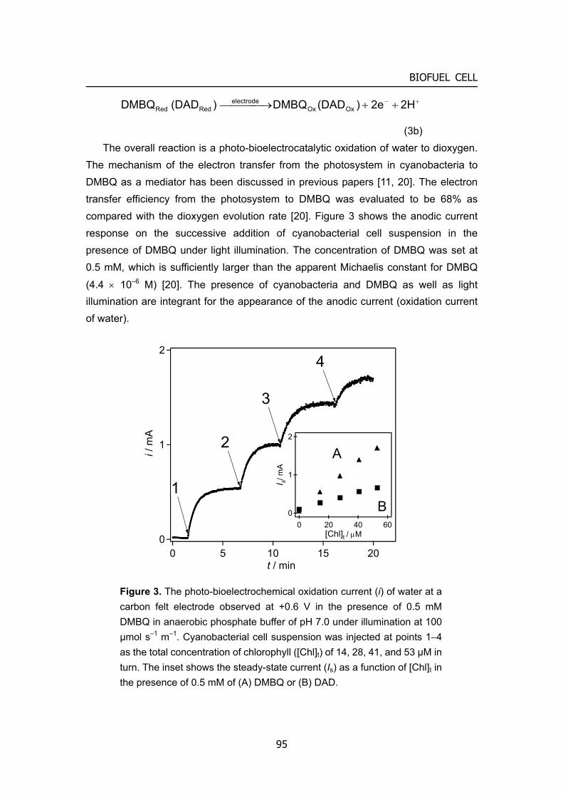
BIOFUEL CELL
+− ++⎯⎯⎯ →⎯ 2H2e )(DADDMBQ )(DAD DMBQ OxOxelectrode
RedRed
(3b) The overall reaction is a photo-bioelectrocatalytic oxidation of water to dioxygen.
The mechanism of the electron transfer from the photosystem in cyanobacteria to DMBQ as a mediator has been discussed in previous papers [11, 20]. The electron transfer efficiency from the photosystem to DMBQ was evaluated to be 68% as compared with the dioxygen evolution rate [20]. Figure 3 shows the anodic current response on the successive addition of cyanobacterial cell suspension in the presence of DMBQ under light illumination. The concentration of DMBQ was set at 0.5 mM, which is sufficiently larger than the apparent Michaelis constant for DMBQ
(4.4 × 10⁻⁶ M) [20]. The presence of cyanobacteria and DMBQ as well as light illumination are integrant for the appearance of the anodic current (oxidation current of water).
2
1
0
i / m
A
20151050t / min
4
3
2
1
2
1
A
0
I s/ m
A
B20 400[Chl]t / μM
60
Figure 3. The photo-bioelectrochemical oxidation current (i) of water at a carbon felt electrode observed at +0.6 V in the presence of 0.5 mM DMBQ in anaerobic phosphate buffer of pH 7.0 under illumination at 100 μmol s–1 m–1. Cyanobacterial cell suspension was injected at points 1−4 as the total concentration of chlorophyll ([Chl]t) of 14, 28, 41, and 53 μM in turn. The inset shows the steady-state current (Is) as a function of [Chl]t in the presence of 0.5 mM of (A) DMBQ or (B) DAD.
95
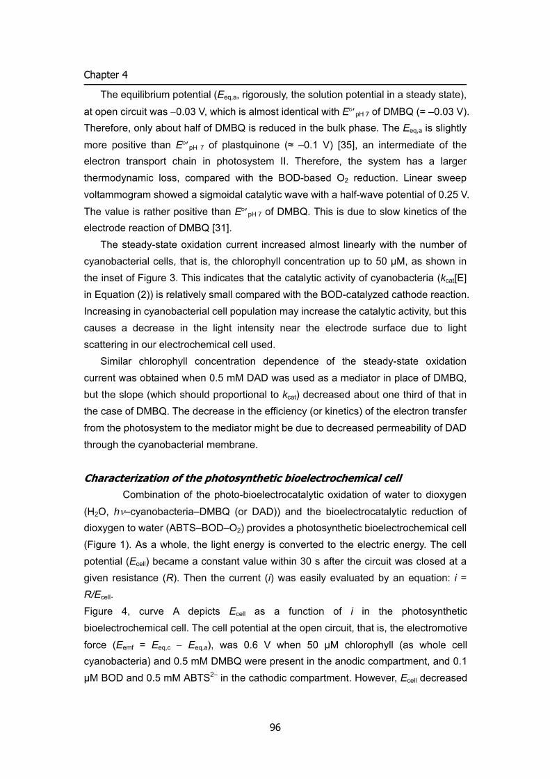
Chapter 4
The equilibrium potential (Eeq,a, rigorously, the solution potential in a steady state),
at open circuit was −0.03 V, which is almost identical with E°′pH 7 of DMBQ (= –0.03 V). Therefore, only about half of DMBQ is reduced in the bulk phase. The Eeq,a is slightly
more positive than E°′pH 7 of plastquinone (≈ –0.1 V) [35], an intermediate of the electron transport chain in photosystem II. Therefore, the system has a larger thermodynamic loss, compared with the BOD-based O2 reduction. Linear sweep voltammogram showed a sigmoidal catalytic wave with a half-wave potential of 0.25 V.
The value is rather positive than E°′pH 7 of DMBQ. This is due to slow kinetics of the electrode reaction of DMBQ [31].
The steady-state oxidation current increased almost linearly with the number of cyanobacterial cells, that is, the chlorophyll concentration up to 50 μM, as shown in the inset of Figure 3. This indicates that the catalytic activity of cyanobacteria (kcat[E] in Equation (2)) is relatively small compared with the BOD-catalyzed cathode reaction. Increasing in cyanobacterial cell population may increase the catalytic activity, but this causes a decrease in the light intensity near the electrode surface due to light scattering in our electrochemical cell used.
Similar chlorophyll concentration dependence of the steady-state oxidation current was obtained when 0.5 mM DAD was used as a mediator in place of DMBQ, but the slope (which should proportional to kcat) decreased about one third of that in the case of DMBQ. The decrease in the efficiency (or kinetics) of the electron transfer from the photosystem to the mediator might be due to decreased permeability of DAD through the cyanobacterial membrane.
Characterization of the photosynthetic bioelectrochemical cell Combination of the photo-bioelectrocatalytic oxidation of water to dioxygen
(H2O, hν–cyanobacteria–DMBQ (or DAD)) and the bioelectrocatalytic reduction of dioxygen to water (ABTS–BOD–O2) provides a photosynthetic bioelectrochemical cell (Figure 1). As a whole, the light energy is converted to the electric energy. The cell potential (Ecell) became a constant value within 30 s after the circuit was closed at a given resistance (R). Then the current (i) was easily evaluated by an equation: i = R/Ecell. Figure 4, curve A depicts Ecell as a function of i in the photosynthetic bioelectrochemical cell. The cell potential at the open circuit, that is, the electromotive
force (Eemf = Eeq,c − Eeq,a), was 0.6 V when 50 μM chlorophyll (as whole cell cyanobacteria) and 0.5 mM DMBQ were present in the anodic compartment, and 0.1 μM BOD and 0.5 mM ABTS2– in the cathodic compartment. However, Ecell decreased
96
BIOFUEL CELL
0.15
with i, and the short circuit current (isc) at Ecell = 0 was about 1 mA. Figure 4, curve B shows the cell power (P = EcellI) as a function of i. The maximum power (Pmax) of this photosynthetic bioelectrochemical cell was 0.13 mW (0.29 W m–2 for projective electrode surface area) at R = 500 Ω and Ecell = 0.26 V (i = 0.5 mA). By considering the light intensity (L = 15 W m–2) at our electrochemical cell surface, the efficiency of the light energy conversion (η = Pmax/L) is calculated to be 1.9%.
The fill factor (ff = Pmax/EemfIsc) is also an important parameter to characterize the cell output. The ff parameter will be unity (that is, Ecell vs. i pattern is rectangular) for the ideal case. In our case, however, ff is only 0.22. In order to examine the factors governing Ecell vs. i relationship, the author measured the potential of the two half-cells simultaneously during the discharge. Plots A and B in Figure 5 represent the electrode potential of the cathodic and anodic compartments (Ec and Ea) as a function of i. It is noteworthy that almost identical relation between i and Ec or between i and Ea
were obtained by linear sweep voltammetry at a scan rate of 10 mV s−1, where the steady-state current was observed (data not shown).
The negative shift in Ec is not so large when i increases at least up to about 1 mA (Figure 5, A). Therefore, the cathodic electrode process is acceptable within the range of i investigated. In the anodic compartment, however, the positive shift in Ea
600
400
200
B0.10
0
Ece
ll / m
V
0.05
0.00
P / mW
A
0.50.0i / mA
1.0
Figure 4. Cell potential (Ecell) () and Power (P) () as a function of the current (i) in the photosynthetic bioelectrochemical cell at different external resistance. Anode: [Chl]t = 50 μM (as whole cell cyanobacteria), [DMBQ]t = 0.5 mM. Cathode: [BOD]t = 0.1 μM, [ABTS2–]t = 0.5 mM.
97
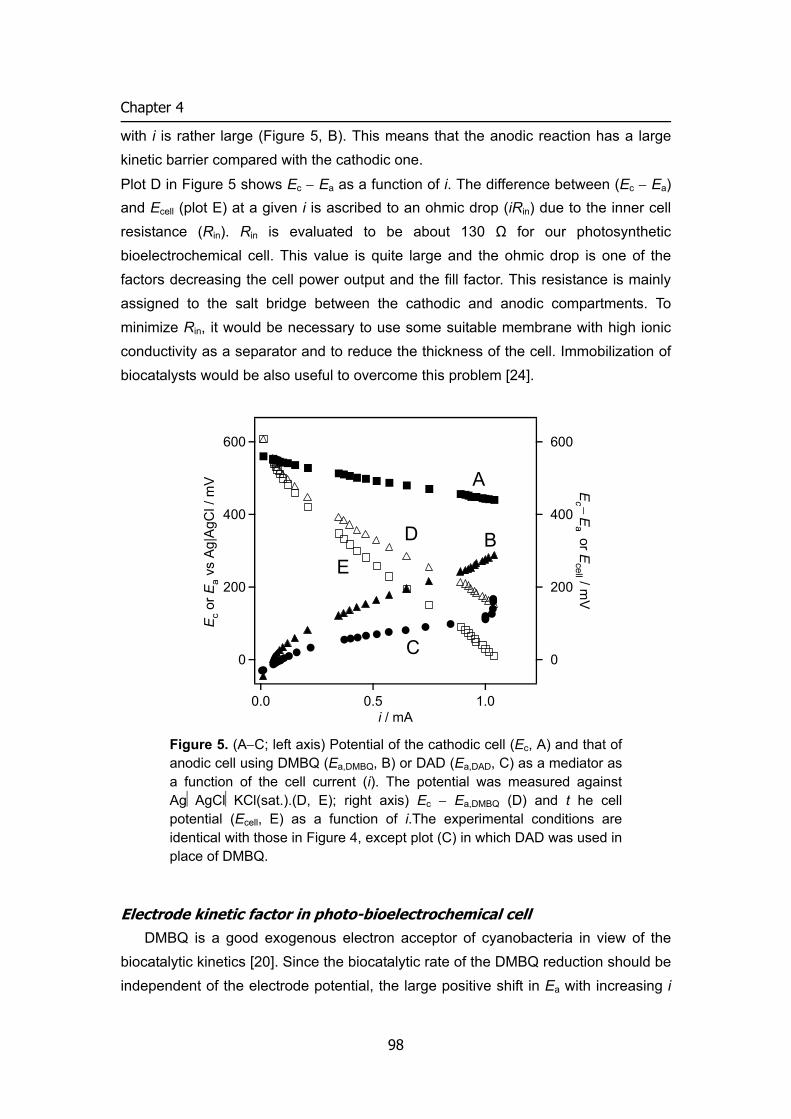
Chapter 4
with i is rather large (Figure 5, B). This means that the anodic reaction has a large kinetic barrier compared with the cathodic one.
Plot D in Figure 5 shows Ec − Ea as a function of i. The difference between (Ec − Ea) and Ecell (plot E) at a given i is ascribed to an ohmic drop (iRin) due to the inner cell resistance (Rin). Rin is evaluated to be about 130 Ω for our photosynthetic bioelectrochemical cell. This value is quite large and the ohmic drop is one of the factors decreasing the cell power output and the fill factor. This resistance is mainly assigned to the salt bridge between the cathodic and anodic compartments. To minimize Rin, it would be necessary to use some suitable membrane with high ionic conductivity as a separator and to reduce the thickness of the cell. Immobilization of biocatalysts would be also useful to overcome this problem [24].
600
400
200
0
Ec − E
a or Ecell / m
V
1.00.50.0i / mA
600
400
200
0
Ec o
r Ea
vs A
g|A
gCl /
mV A
B
C
D
E
Figure 5. (A−C; left axis) Potential of the cathodic cell (Ec, A) and that of anodic cell using DMBQ (Ea,DMBQ, B) or DAD (Ea,DAD, C) as a mediator as a function of the cell current (i). The potential was measured against AgAgClKCl(sat.).(D, E); right axis) Ec − Ea,DMBQ (D) and t he cell potential (Ecell, E) as a function of i.The experimental conditions are identical with those in Figure 4, except plot (C) in which DAD was used in place of DMBQ.
Electrode kinetic factor in photo-bioelectrochemical cell DMBQ is a good exogenous electron acceptor of cyanobacteria in view of the
biocatalytic kinetics [20]. Since the biocatalytic rate of the DMBQ reduction should be independent of the electrode potential, the large positive shift in Ea with increasing i
98
BIOFUEL CELL
(Figure 5, B) is ascribed to a large kinetic barrier of DMBQ in the heterogeneous electron transfer at the anode. Therefore, the author attempted to use DAD as a mediator in place of DMBQ, since DAD exhibits better electrode reaction kinetics than DMBQ. Plot C in Figure 5 shows Ea vs. i relationship when DAD was used as a mediator in the anodic reaction. As expected, the positive shift in Ea with increasing i was smaller than that in the case of DMBQ (Figure 5, B). Eeq,a (=Ecell at i = 0) of the DAD system
was –0.05 V, which is more negative than E°′pH 7 of DAD (0.02 V). However, the limiting current (ca. 1 mA) observed at sufficiently positive Ea (see Figure 5C) is smaller than that of DMBQ. This is due to the decreased efficiency of the electron transfer from cyanobacteria to DAD, as described in 3.2. (Figure 3, inset). In spite of the decreased biocatalytic electron transfer efficiency, the DAD system exhibited a maximum power of 0.17 mW (0.38 W m–2 for projective electrode surface area) at R = 400 Ω at Ecell = 0.26 V, and its ff and η were improved up to 0.29 and 2.5 %, respectively. This is of course due to the better electrode kinetics of DAD than DMBQ. Therefore, it is important to consider electrode kinetic factor also in selecting mediators and electrode materials.
Concluding remarks This is the first report on the photosynthetic bioelectrochemical cell that utilizes
biocatalysts in both anode and cathode compartments. The most important point is utilization of the BOD system to reduce O2 to H2O in the cathodic half-cell. In principle, O2 is generated from H2O in the photosystem in the anodic half-cell. Therefore, this cell may be an ideal device converting the light energy into the electric energy with no special chemical fuel and no product. However, the power is not enough for practical use at the present stage, and unfortunately the cell performance is inferior to the best one of the prototype photosynthetic bioelectrochemical cells (Eemf = 0.8 V, Pmax = 0.19 mW cm–2, the maximum current density ≈ 0.4 mA cm–2), although the prototype cell utilizes ferricyanide as a cathodic (oxidizing) fuel [19].
In this work, the author has also proposed an evaluation method of the cell characteristics on the basis of the potential vs. current relationship. The analysis has indicated that most of the limiting factors concern the anodic half-cell. One of the problems is a large thermodynamic loss in the electron transfer from the photosystem
to the mediator. To minimize the thermodynamic loss, E°′pH of mediators should be more negative, although such mediators might have large kinetic barrier in the biocatalytic electron transfer from photosystems, and increase a risk of backward
99
Chapter 4
reaction leakage due to the re-oxidation of the reduced form of mediators with O2.
2-Hydroxy-1,4-naphthoquinone (HNQ), of which E°′pH 7 (= –0.345 V) is more negative than that of DMBQ, was utilized in the prototype photosynthetic cell [19]. However, HNQ did not work as a mediator in our case. The discrepancy suggests that the mediator performance depend on the cell species used. Therefore Eemf will be able to increase by the selection of cyanobacterial cell species and the mediator.
The second point is the low current density in the anodic half-cell, which is responsible in part for low cell power (Figure 5). In our cell, the photo-anodic current density increased linearly with the cyanobacterial population (Figure 3, inset). Therefore, increasing the cell population may increase the current density. However, since the increase in the cell density causes energy loss by light scattering, the improvement of the cell design is required. The utilization of photosystem II-enriched membrane fractions is also useful to increase the current density, as evidenced in the potentiostatic experiments on photo-bioelectrochemical oxidation of water [10,11].
The third point is the electrode kinetics of mediators. This may be overcome by selecting a suitable mediators and electrode material. The reduction of the inner cell resistance is also the problem, which confronts us. For this purpose, the author tried to immobilize biocatalysts as well as mediators on electrode surface in the next stage. The author will address these live issues to improve this novel photosynthetic cell.
References
[1] B. O’Regan, M. Grätzel, Nature, 353, 737 (1991). [2] G. T. R. Palmore, G. M. Whitesides, ACS Symp. Series No.556, 271 (1994). [3] H. Ochiai, H. Shibata, T. Matsuo, K. Hashinokuchi, M. Yukawa, Agric. Biol.
Chem., 41, 721 (1977). [4] H. Ochiai, H. Shibata, T. Matsuo, K. Hashinokuchi, I. Inamura, Agric. Biol. Chem.,
42, 683 (1978). [5] W. Heahnel, H. J. Hochmeimer, Bioelectrochem. Bioenerg., 6, 563 (1979). [6] E. Tyszkiewicz, H. Bottin, E. Roux, Bioelectrochem. Bioenerg., 9, 157 (1982). [7] M. Okano, T. Iida, H. Shinohara, H. Kobayashi, T. Mitamura, Agric. Biol. Chem.,
48, 1977 (1984). [8] H.A.O. Hill, N.J. Walton, P. Whitford, J. Electroanal. Chem., 187, 109 (1985). [9] S. Lemieux, R. Carpentier, , J. Photochem. Photobiol., 2B, 221 (1988). [10] T. Ikeda, M. Senda, T. Shiraishi, M. Takahashi, K. Asada, Chem. Lett., 913
(1989). [11] K. Amako, H. Yanai, T. Ikeda, T. Shiraishi, M. Takahashi, K. Asada, J.
100
BIOFUEL CELL
Electroanal. Chem., 362, 71 (1993). [12] M. Mimeault, R. Carpentier, Bioelectrochem. Bioenerg., 22, 145 (1989). [13] R. Carpentier, S. Lemieux, M. Mimeault, M. Purcell, D. C. Goetze,
Bioelectrochem. Bioenerg., 22, 145 (1989). [14] H. Ochiai, H. Shibata, Y. Sawa, M. Shoga, S. Ohta, Appl. Biochem. Biotechnol.,
8, 289 (1983). [15] K. Tanaka, R. Tamamushi, T. Ogawa, J. Chem. Tech. Biotechnol., 35B, 191
(1985). [16] K. Tanaka, N. Kashiwagi, T. Ogawa, J. Chem. Tech. Biotechnol., 42, 235
(1988). [17] T. Yagishita, T. Horigome, K. Tanaka, J. Chem. Tech. Biotechnol., 56, 393
(1993). [18] N. Martens, E. A. H. Hall, Photochem. Photobiol., 59, 91 (1994). [19] T. Yagishita, S. Sawayama, K. Tsukahara, and T. Ogi, Solar Energy, 61, 347
(1997). [20] M. Torimura, A. Miki, A. Wadano, K. Kano, T. Ikeda, J. Electroanal. Chem., 496,
21 (2001). [21] G. T. R. Palmore, H-H. Kim, J. Electroanal. Chem., 464, 110 (1999). [22] H. A. O. Hill, N. J. Walton, I. J. Higgins, FEBS Lett., 126, 282 (1981). [23] H. A. O. Hill, N. J. Walton, J. Am. Chem. Soc., 104, 6515 (1982). [24] E. Katz, I. Willner, A. B. Kotlyar, J. Electroanal. Chem., 479, 64 (1999). [25] S. Tsujimura, H. Tatsumi, J. Ogawa, S. Shimizu, K. Kano, T. Ikeda, J. Electroanal.
Chem., 496, 69 (2001). [26] S. Izawa, in Pietro, A. S. (Ed.), Methods in Enzymology, Vol. 69, Academic Press,
Ch. 39 (1980). [27] R. Rippaka, J. Deruelles, J. B. Waterbuy, M. Herdman, R. Y. Stanier, J. Gen.
Microbiol., 111, 1 (1979) . [28] G. Mackinnery, J. Biol. Chem., 140, 315 (1941). [29] D. T. Arnon, Plant Physiol., 24, 1 (1949) [30] A. Shimizu, J-H. Kwon, T. Sasaki, T. Satoh, N. Sakurai, T. Sakurai, S. Yamaguchi,
T. Samejima, J. Biochem., 125, 662 (1999). [31] Y. Ogino, K. Takagi, K. Kano, and T. Ikeda, J. Electroanal. Chem., 396, 517
(1995).
[32] K. Kato, K. Kano, T. Ikeda, J. Electrochem. Soc., 147, 1449 (2000). [33] K. Kano, T. Ohgaru, H. Nakase, T. Ikeda, Chem. Lett., 439 (1996).
[34] T. Ohgaru, H. Tatsumi, K. Kano, T. Ikeda, J. Electroanal. Chem., 496, 37 (2001).
101

Chapter 4
[35] A. Smith, P. Datta, G. Smith, R. Bentley, and others, Oxford Dictionary of Biochemistry and Molecular Biology, Oxford University Press, UK, 516 (2000)
102
BIOFUEL CELL
Glucose/O2 biofuel cell operating at physiological conditions 3
A glassy carbon electrode modified with bilirubin oxidase (BOD) cross-linked with Os
redox polymer functions as a bio-cathode for a 4-electron reduction of O2 under
neutral conditions. On the other hand, a glassy carbon electrode modified with
pyrroloquinoline quinone-dependent soluble glucose dehydrogenase (sGDH)- or
glucose oxidase cross linked with Os redox polymer functions as a bio-anode for a
2-electron oxidation of glucose. A prototype of a one-compartment glucose biofuel cell
without a separator was constructed by using the BOD-modified cathode and the
sGDH-modified anode. The maximum power density was 0.058 mW cm–2. The loss in
the power is discussed in terms of thermodynamics and kinetics.
Introduction
Increasing attention has been recently paid to biofuel cells, which are devices for converting chemical energy into electrical energy by means of enzymatic oxidations of biological reductants such as H2, NADH, alcohols and carbohydrates at anodes [1] and enzymatic reductions of O2 and others at cathodes. The advantages of biofuel cells are ease in handling, simplicity of cell structure and flexibility in size (which allow miniaturization and bio-implantable type), mild conditions for operation, and minimized pollution in scrapping.
The author has constructed prototypes of an H2/O2 biofuel cell [2] and a photo-respiration-like biocell [3]. Many attentions are also drawn to glucose as a promising biofuel [4, 5], since it has high solubility in water, and glucose biofuel cells would be safe and easy in handing. The power density of the prototype biofuel cells is, however, lower in two or three orders magnitudes than that of conventional fuel cells. In biofuel cells, some suitable redox mediators are required to shuttle electrons between enzymes and electrodes. The thermodynamic loss in biofuel cells is predominantly governed by the difference in the formal potential (Eo’) between fuels and mediators. On the other hands, kinetic loss is governed by the electrode reaction of mediators and the enzymatic reaction as well as cell resistances [2]. Therefore, selection and co-immobilization of enzymes and mediators as well as cell designs are very important to improve the power density of biofuel cells.
Co-immobilization of enzymes and mediators on an electrode may realize a high current density due to the mediated enzyme electrochemical reaction because of
103
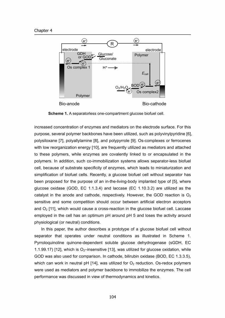
Chapter 4
increased concentration of enzymes and mediators on the electrode surface. For this purpose, several polymer backbones have been utilized, such as polyvinylpyridine [6], polysiloxane [7], polyallylamine [8], and polypyrrole [9]. Os-complexes or ferrocenes with low reorganization energy [10], are frequently utilized as mediators and attached to these polymers, while enzymes are covalently linked to or encapsulated in the polymers. In addition, such co-immobilization systems allows separator-less biofuel cell, because of substrate specificity of enzymes, which leads to miniaturization and simplification of biofuel cells. Recently, a glucose biofuel cell without separator has been proposed for the purpose of an in-the-living-body implanted type of [5], where glucose oxidase (GOD, EC 1.1.3.4) and laccase (EC 1.10.3.2) are utilized as the catalyst in the anode and cathode, respectively. However, the GOD reaction is O2 sensitive and some competition should occur between artificial electron acceptors and O2 [11], which would cause a cross-reaction in the glucose biofuel cell. Laccase employed in the cell has an optimum pH around pH 5 and loses the activity around physiological (or neutral) conditions.
In this paper, the author describes a prototype of a glucose biofuel cell without separator that operates under neutral conditions as illustrated in Scheme 1. Pyrroloquinoline quinone-dependent soluble glucose dehydrogenase (sGDH, EC 1.1.99.17) [12], which is O2–insensitive [13], was utilized for glucose oxidation, while GOD was also used for comparison. In cathode, bilirubin oxidase (BOD, EC 1.3.3.5), which can work in neutral pH [14], was utilized for O2 reduction. Os-redox polymers were used as mediators and polymer backbone to immobilize the enzymes. The cell performance was discussed in view of thermodynamics and kinetics.
BOD
Os complex2O2/H2O
Glucose/ Gluconate
Os complex 1
e-e-
e-
e-
e-
e-
e-e-
electrode electrode
Ecell
Bio-anode Bio-cathode
H+
R
GDH or GOD
Polymer
Polymer
Scheme 1. A separatorless one-compartment glucose biofuel cell.
104
BIOFUEL CELL
Experimental
Enzymes and redox polymers BOD from Myrothecium verrucaria and GOD from Aspergius niger were obtained
from Amano Pharmaceutical Co. and Oriental Yeast Co., respectively. sGDH from Acinetobactor calcoaceticus was donated from Prof. Duine. Poly(vinylpyridine) complexed with Os(2,2’-bipyridine)2Cl and quaternized with bromoethylamine (1) [13] and poly1-vinylimidazole complexed with Os(4,4’-dimethyl-2,2’-bipyridine)2Cl (2) [15] were prepared according to the literatures; 1 was used as a redox polymer to link a BOD reaction to a cathode reaction , and 2 to link GOD or sGDH reactions to an anode reaction.
Preparation of enzyme-linked redox polymer-modified electrodes A glassy carbon disk electrode (3 mm in diameter) was polished with alumina
powder (0.5 μm) and sonicated for 5 min in deionized water. On a bare electrode surface as a cathode, 5 μL of 1 solution (25 mg ml–1) and 2 μL of BOD solution (20 mg ml–1 in 50 mM phosphate buffer, pH 7.0) were syringed and mixed with a syringe needle. To the mixture, 1.2 μL of poly(ethylene glycol) diglycidyl ether (2.5 mg ml–1, PEG, Aldrich) was added and mixed. The electrode was left overnight for dryness at room temperature to prepare a bio-cathode modified with BOD cross-linked with 1. Similarly, bio-anodes were prepared using GOD or sGDH as enzyme 2 as a redox polymer.
Electrochemical measurement Cyclic voltammetry were performed using a Bioanalytical Systems CV-100W
electrochemical analyzer. A platinum wire and Ag|AgCl|KCl(sat.) were used as the counter and reference electrode, respectively. Electrochemical measurements were carried out in phosphate buffer of 50 mM, pH 7.0 at 25 °C unless stated otherwise. In the experiments on the sGDH-linked electrode, MOPS buffer containing 3 mM CaCl2 was used as electrolytic solution, MOPS being used in order to avoid the precipitation of Ca2+ which is essential for the activation of sGDH. A prototype of the biofuel cell was constructed using BOD linked electrode as cathode and sGDH linked electrode as anode. The anode and cathode of the cell were connected through a resistor. The cell potentials were measured with an electrometer (HE-106, Hokuto Denko, Japan.) at each value of the resistance, which was changed stepwise from 1 MΩ to 1 kΩ, All potentials are referred to the Ag|AgCl|KCl(sat.) electrode.
105
Chapter 4
Results and discussion
Cyclic voltammetry of bio-cathode The current-potential curves of cathode and anode were separately investigated
to characterize the electrode reactions. BOD-linked-1-coated electrode (bio-cathode) gave a surface redox wave with a formal potential (E°’1) of 0.35 V under deaerated conditions, as shown in Figure 1(A). The polymer 1 shows good reversibility and is very stable. The wave is ascribed to the Os(III/II) redox reaction of 1 as shown by Heller [16]. Upon passing O2 gas as the substrate of BOD, the typical catalytic current was observed (Figure 1(B)). The overall electrode process is a 4-electron reduction of O2 to H2O. The catalytic constant (kcat) and the Michaelis constant (Km) in the reaction between BOD and Os(2,2’-bipyridine)2(imidazole)2 (as a monomer model of 1) were evaluated as 3300 s–1 and 0.23 mM, respectively. Compared with those of 2,2’-azinobis (3-ethylbenzothiazolin-6-sulfonate) (ABTS; kcat = 830 s–1, Km = 0.011 mM, Eo’ = 0.51 V) as a very effective artificial electron donor of BOD [14], it can be concluded that Os(II) in 1 works as an excellent electron donor of BOD, although the thermodynamic loss (Eo’O2/H2O – Eo’1 = 0.27 V) is larger by 0.15 V than in the case of ABTS.
Similar bioelectrochemical reductions of O2 have been reported using laccase-linked Os-redox polymer at pH 4.7 [17] and 5.0 [18]. For the latter case, the Eo’ value of the polymer is as high as 0.55 V, but the thermodynamic loss is comparable with that of our case, by considering Eo’O2/H2O at pH 5. The use of the laccase-linked electrodes is limited in slightly acidic solution. This is in marked contrast with the BOD-linked electrode, which remains its activity under neutral conditions.
Cyclic voltammetry of two-types of bio-anodes The polymer 2 gave a reversible surface redox wave of Os(III/II) (data not shown),
but the formal potential (Eo’2) is 0.15 V due to the electron donating property of the ligands compared with 1. Figure 1(C) shows a voltammograms observed at the GOD-linked-2-coated bio-anode in the presence of glucose. A typical catalytic wave was observed as shown in the previous paper [15]. The overall electrode process is a 2-electron oxidation of glucose to gluconate, where Os(III) in 2 functions as an artificial electron acceptor of GOD in place of O2. In order to achieve fast electron transfer from GOD to artificial electron acceptors, relatively large difference is
required between Eo’mediaor and Eo’GOD (≈ –0.35 V at pH 7.0 [19]) [20-23]. The minimum value of Eo’mediaor – Eo’GOD seems to be about 0.5 V for mediators to be used in
106
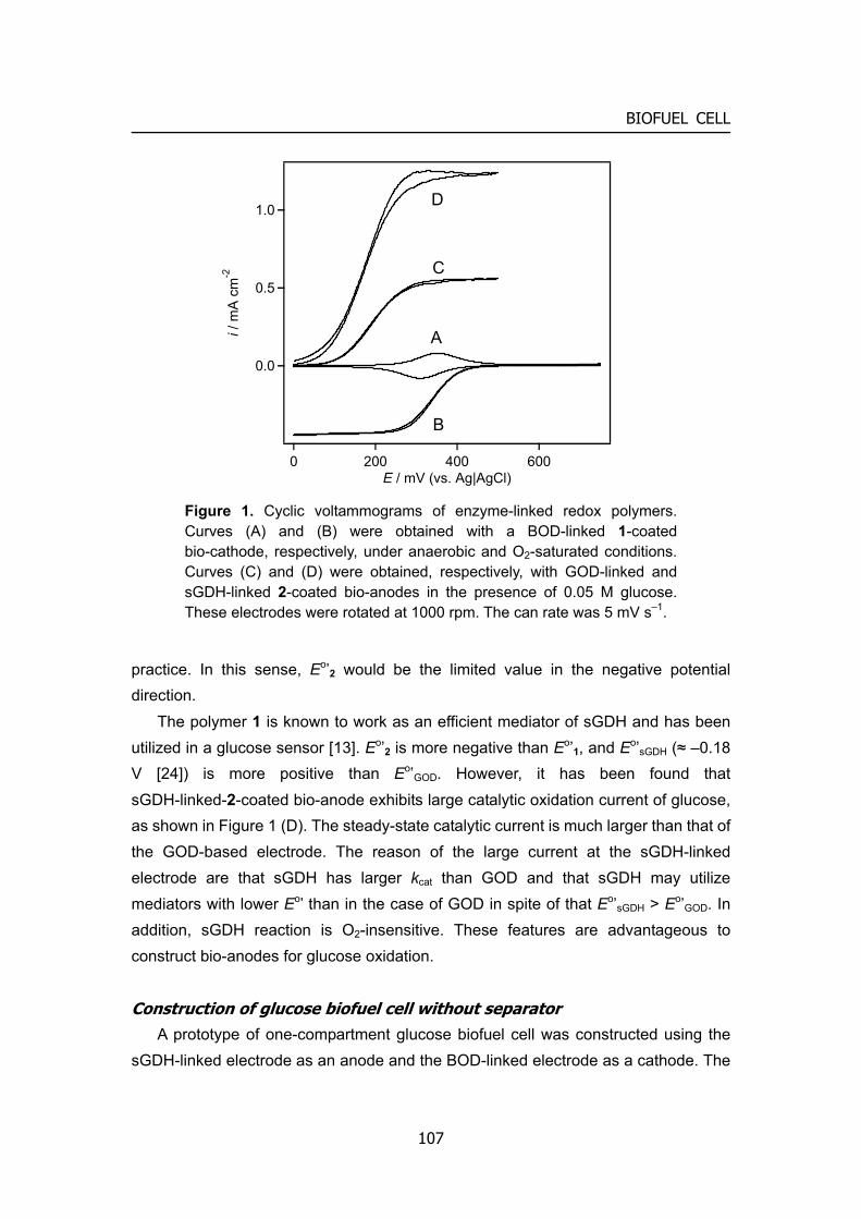
BIOFUEL CELL
practice. In this sense, Eo’2 would be the limited value in the negative potential direction.
The polymer 1 is known to work as an efficient mediator of sGDH and has been utilized in a glucose sensor [13]. Eo’2 is more negative than Eo’1, and Eo’sGDH (≈ –0.18 V [24]) is more positive than Eo’GOD. However, it has been found that sGDH-linked-2-coated bio-anode exhibits large catalytic oxidation current of glucose, as shown in Figure 1 (D). The steady-state catalytic current is much larger than that of the GOD-based electrode. The reason of the large current at the sGDH-linked electrode are that sGDH has larger kcat than GOD and that sGDH may utilize mediators with lower Eo’ than in the case of GOD in spite of that Eo’sGDH > Eo’GOD. In addition, sGDH reaction is O2-insensitive. These features are advantageous to construct bio-anodes for glucose oxidation.
Construction of glucose biofuel cell without separator A prototype of one-compartment glucose biofuel cell was constructed using the
sGDH-linked electrode as an anode and the BOD-linked electrode as a cathode. The
1.0
0.5
A
B
C
D
0.0
i / m
A c
m-2
200 4000E / mV (vs. Ag|AgCl)
600
Figure 1. Cyclic voltammograms of enzyme-linked redox polymers. Curves (A) and (B) were obtained with a BOD-linked 1-coated bio-cathode, respectively, under anaerobic and O2-saturated conditions. Curves (C) and (D) were obtained, respectively, with GOD-linked and sGDH-linked 2-coated bio-anodes in the presence of 0.05 M glucose. These electrodes were rotated at 1000 rpm. The can rate was 5 mV s–1.
107
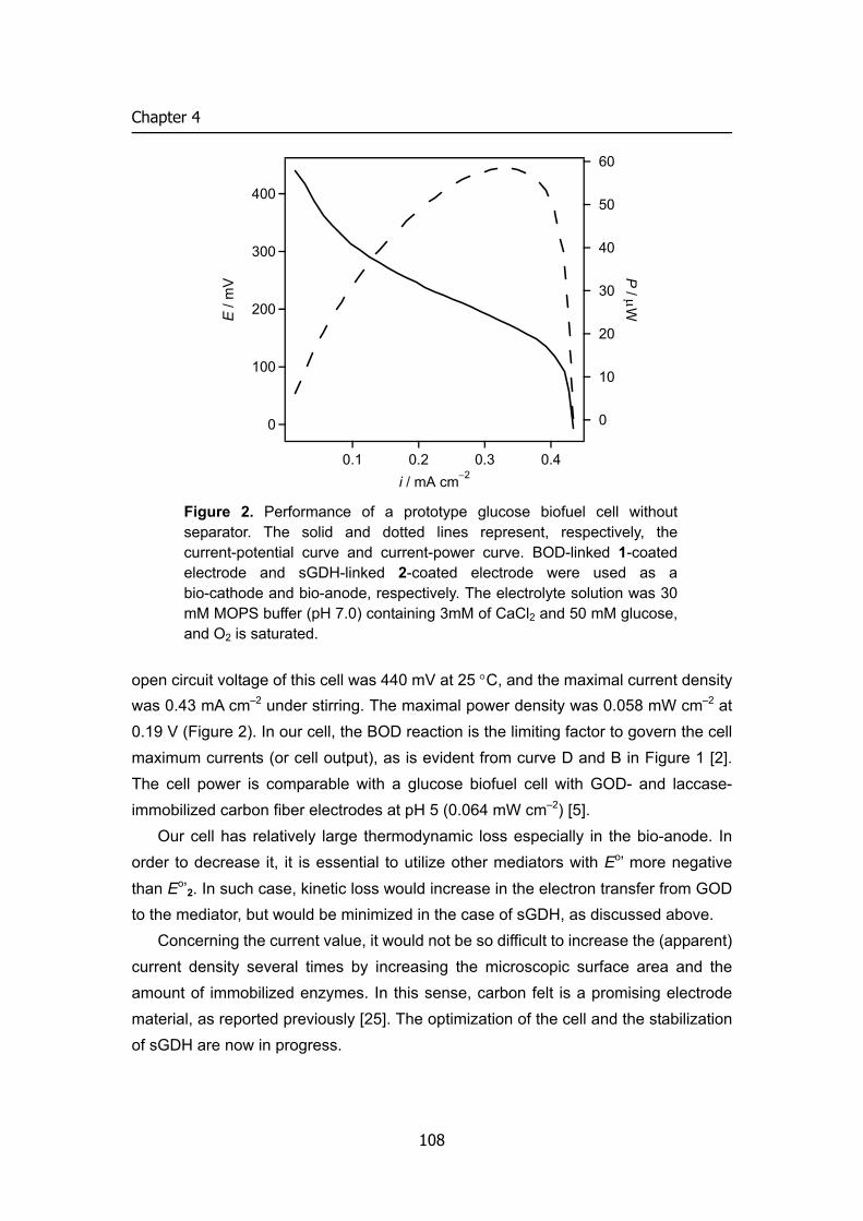
Chapter 4
60
open circuit voltage of this cell was 440 mV at 25 °C, and the maximal current density was 0.43 mA cm–2 under stirring. The maximal power density was 0.058 mW cm–2 at 0.19 V (Figure 2). In our cell, the BOD reaction is the limiting factor to govern the cell maximum currents (or cell output), as is evident from curve D and B in Figure 1 [2]. The cell power is comparable with a glucose biofuel cell with GOD- and laccase- immobilized carbon fiber electrodes at pH 5 (0.064 mW cm–2) [5].
Our cell has relatively large thermodynamic loss especially in the bio-anode. In order to decrease it, it is essential to utilize other mediators with Eo’ more negative than Eo’2. In such case, kinetic loss would increase in the electron transfer from GOD to the mediator, but would be minimized in the case of sGDH, as discussed above.
Concerning the current value, it would not be so difficult to increase the (apparent) current density several times by increasing the microscopic surface area and the amount of immobilized enzymes. In this sense, carbon felt is a promising electrode material, as reported previously [25]. The optimization of the cell and the stabilization of sGDH are now in progress.
400
300
200
100
50
40
0
E /
mV 30
0.40.30.20.1i / mA cm−2
20
10
0
P / μW
Figure 2. Performance of a prototype glucose biofuel cell without separator. The solid and dotted lines represent, respectively, the current-potential curve and current-power curve. BOD-linked 1-coated electrode and sGDH-linked 2-coated electrode were used as a bio-cathode and bio-anode, respectively. The electrolyte solution was 30 mM MOPS buffer (pH 7.0) containing 3mM of CaCl2 and 50 mM glucose, and O2 is saturated.
108
BIOFUEL CELL
References
[1] G. T. R. Palmore, G. M. Whitesides, ACS Symp. Series No.556, 271 (1994). [2] S. Tsujimura, M. Fujita, H. Tatsumi, K. Kano, and T. Ikeda, Phys. Chem. Chem.
Phys., 3, 1331 (2001). [3] S. Tsujimura, A. Wadano, K. Kano, and T. Ikeda, Enz. Microbial Tech., 29, 225
(2001). [4] E. Katz, I. Willner, and A. B. Kotlyar, J. Electroanal. Chem., 479, 64 (1999). [5] T. Chen, S. C. Barton, G. Binyamin, Z. Gao, Y. Zhang, H-H. Kim, and A. Heller, J.
Am. Chem. Soc., 123, 8630 (2001). [6] A. Heller, Acc. Chem. Res., 23, 128 (1990). [7] P. D. Hale, T. Imnagaki, H. I. Karan, Y. Okamoto, and T. A. Skotheim, J. Am. Chem.
Soc., 111, 3482 (1989). [8] E. J. Calvo, C. Damlowicz, and L. Diaz, J. Electroanal. Chem., 369, 279 (1994). [9] A. Haimerl and A. Merz, Angew. Chem., 98, 179 (1986). [10] R.A. Marcus and N. Sutin, Biochim. Biophys. et Acta, 811, 265 (1985). [11] R. Matsumoto, M. Mochizuki, K. Kano, and T. Ikeda, Anal. Chem., in press. [12] A. J. J. Olsthoorn and J. A. Duine, Arch. Biochem. Biophys., , 336, 42 (1996). [13] L. Ye, M. Hammerle, A. J. J. Olsthoorn, W. Schuhmann, H. Schmidt, J. A. Duine,
and A. Heller, Anal. Chem., 65, 238 (1993). [14] S. Tsujimura, H. Tatsumi, J. Ogawa, S. Shimizu, K. Kano, and T. Ikeda, J.
Electroanal. Chem., 496, 69 (2001). [15] T. J. Ohara, R. Rajagopalan, and A. Heller, Anal. Chem., 66, 2451 (1994). [16] B. A. Gregg and A. Heller, J. Phys. Chem., 95, 5970 (1990). [17] F. Trudeau, F. Daigle, and D. Leech, Anal. Chem., 69, 882 (1997). [18] S. C. Barton. H-H. Kim, G. Binyamin, Y. Zhang, and A. Heller, J. Phys. Chem. B,
105, 11917 (2001). [19] Eo’GOD at pH 7.0 was theoretically calculated from the literature (M. T. Stankovich,
L. M. Schopfer, and V. Massey, J. Biol. Chem., 253, 4971 (1978)). [20] T. Ikeda, H. Hiasa, and M. Senda, Redox chemistry and interfacial behavior of
biological molecules (Ed. G. Dryhurst and K. Niki), Plenum Pless, New York, N.Y., p 193 (1988).
[21] J. J. Kulys and N. K. Cenas, Biochim. Biophys. Acta, 744, 57 (1983). [22] S. M. Zakeeruddin, D. M. Fraser, M-K. Nazeeruddin, and M. Grätzel, J.
Electroanal. Chem., 337, 253 (1992) [23] Y. Nakabayashi, A. Omayu, S. Yagi, K. Nakamura, and J. Motonaka, Anal. Sci.,
17. 945 (2001)
109
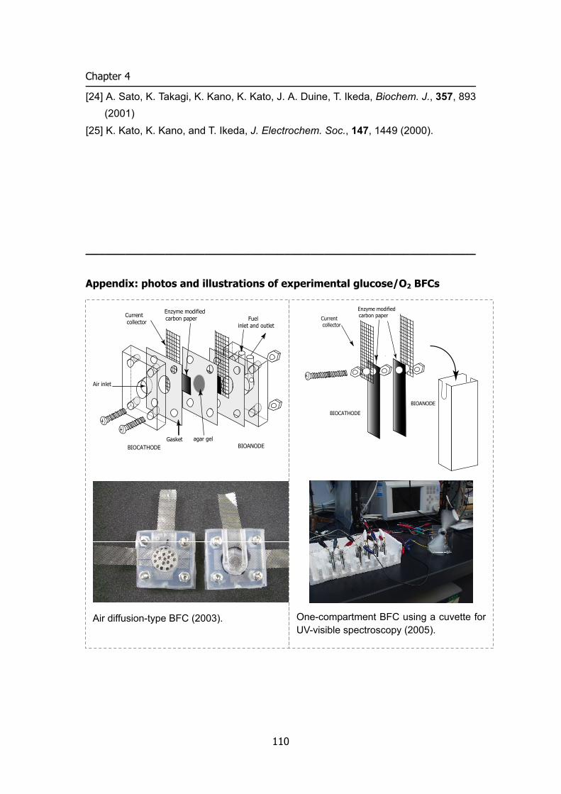
Chapter 4
[24] A. Sato, K. Takagi, K. Kano, K. Kato, J. A. Duine, T. Ikeda, Biochem. J., 357, 893 (2001)
[25] K. Kato, K. Kano, and T. Ikeda, J. Electrochem. Soc., 147, 1449 (2000).
___________________________________________________________
Appendix: photos and illustrations of experimental glucose/O2 BFCs
BIOCATHODE BIOANODE
Enzyme modifiedcarbon paperCurrent
collector Fuelinlet and outlet
Gasket agar gel
Air inlet
Air diffusion-type BFC (2003).
BIOCATHODE
BIOANODE
Enzyme modifiedcarbon paperCurrent
collector
One-compartment BFC using a cuvette for UV-visible spectroscopy (2005).
110
5
Redox titration of redox proteins Development of a novel bulk electrolysis method for in situ spectroscopic measurements
One-compartment bulk electrolysis and simultaneous spectroscopic measurements
are realized in a conventional spectroscopic cuvette without separator by using a
mesh-type working electrode with extremely large surface area and a wire-type
counter electrode with very small surface area. Spectrophotometric monitoring
revealed complete electrolysis in a first-order kinetics. This technique was applied to
mediated titration of cytochrome c and bilirubin oxidase for determining their redox
potentials. Kinetics consideration is briefed for solution redox reaction between protein
and mediator. The subtraction of spectral background due to mediator adsorption is
very easy because of high reproducibility. The experiments can be done under
completely anaerobic conditions. Low absorbance protein samples (of low
concentrations or small absorption coefficients) and hydrophobic proteins (such as
membrane-bound proteins) are acceptable for measurements.
Introduction
There are substantial demands for knowing redox potentials (E°′P) of proteins,
since E°′P is one of the most important physicochemical parameters for better
understanding of physiological electron transfer processes and also for developments
of biosensors, bioreactors, and biofuel cells. Cyclic voltammetry or other voltammetric
methods might be applied to direct determination of E°′P at suitable electrodes [1].
However, direct electrode reactions of redox proteins are often irreversible or
undetectable, since redox centers of proteins are usually bound strongly within deep
inside of the polypeptide chains, and strong adsorption properties of proteins may
lead to denaturation on electrode surface. Thus, mediator-assisted potentiometric
111
Chapter 5
titration coupled with spectroscopic detection is most frequently employed for
determining E°′P [2,3]. However, volume change by addition of titrants often
decreases the reproducibility of the spectroscopic response, which makes difficult to
background subtraction for mediator adsorption. In addition, it takes long time for
equilibration.
Controlled potential bulk electrolysis is, in principle, convenient for redox titration,
since the solution potential may be controlled by the working electrode potential, no
volume change occurs during titration, and bulk electrolytic methods can be easily
coupled with several spectroscopic methods. Optically transparent thin-layer (OTT)
[1] cell allows in situ UV-visible absorption spectroelectrochemistry [4]. Since proteins
can be indirectly electrolyzed in the presence of mediators, OTT
spectroelectrochemical techniques may be used as the alternative for determining
E°′P [5]. The disadvantages of the OTT technique might be that it also takes long time
to reach equilibrium, that relatively high concentration of samples are needed
because of very short light-path length, and that it is very difficult to remove dissolved
dioxygen (O2) which complicates redox titration of O2-sensitive proteins and
mediators.
In order to overcome these disadvantages of the above methods,
(continuous-flow) column electrolytic spectroelectrochemical technique has been
proposed for E°′P determination [6–9]. The method allows rapid and quantitative
electrolysis, and gives very stable background in spectroscopic detection even in the
presence of redox mediators. One serious drawback is adsorption of (hydrophobic)
proteins and mediators on the surface of column electrodes.
Very recently, the author has proposed a separator-less one-compartment bulk
electrolytic method, in which the area of the counter electrode (AC) is sufficiently small
compared with that of the working electrode (AW) [10]. The principle of the method is
that when AC << AW, the current density at the counter electrode becomes much
larger than that at the working electrode, and then the potential of the counter
electrode must move to a potential sufficient for electrolysis of solvent or electrolytes,
which minimizes re-electrolysis of the product(s) generated at the working electrode.
Since any separator is not required between working and counter electrodes,
one-compartment bulk electrolysis can be achieved in any kind of cells including
spectroscopic cuvettes, which would realize a variety of spectroelectrochemical
experiments. Our attempt in this work is to apply the separator-less one-compartment
112
REDOX TITRATION
bulk electrolysis method to the determination of E°′P. Cytochrome c and bilirubin
oxidase (BOD) were selected, respectively, as a typical redox protein and an enzyme
very sensitive to O2 with low absorption coefficients.
Experimental
Chemicals Potassium hexacyano ferrate (II) (K4[FeII(CN)6]) and cytochrome c (from horse
heart) were purchased from Wako Pure Chemicals, Co Ltd (Japan) and used without further purification. Metal complexes [Os(4,4’-dimethyl-2,2’-dipyridyl)2(Imidazole)Cl](PF6)2 [11], potassium octacyano tungstate (IV) (K4[W(CN)8]) [12], potassium hexacyano osmate (III) (K4[Os(CN)6]) [13], and potassium octacyano molybdate (IV) (K4[Mo(CN)8]) [14] were synthesized according to the literature. BODs (EC 1.3.3.5, 3.31 U mg–1) from Myrothecium verrucaria and Trachderma tsunodae were a gift from Amano Enzyme Inc. (Japan) and purchased from Takara Shuzo (Japan), respectively. All other chemicals used were of reagent grade.
Electrolysis cell A quartz cuvette for UV-visible spectroscopy (10 mm × 10 mm × 42 mm) was used
as an electrolysis cell. As shown in Figure 1, a Pt mesh (100 mesh, 10 mm × 20 mm) was attached at the bottom and two frosted sides of the cuvette and used as the working electrode. A Pt wire (1 mm diameter) as the auxiliary electrode was immersed into solution to a depth of about 1 mm. An Ag|AgCl|sat.KCl (Hokuto Denko Co., Japan) was used as the reference electrode, to which all potentials are referred, unless otherwise stated. These electrodes were fixed with a silicon cap on the top of the cell. Special care was taken for the electrode arrangement not to block the light path with the electrodes.
113
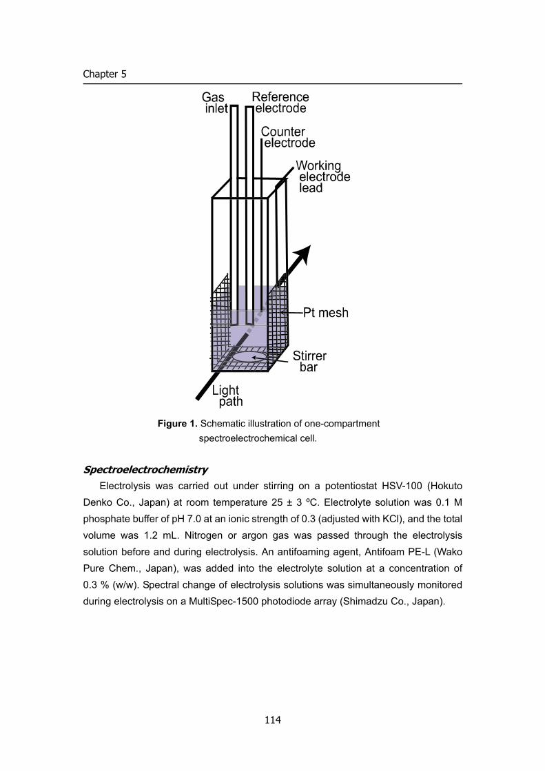
Chapter 5
Figure 1. Schematic illustration of one-compartment spectroelectrochemical cell.
Spectroelectrochemistry Electrolysis was carried out under stirring on a potentiostat HSV-100 (Hokuto
Denko Co., Japan) at room temperature 25 ± 3 ºC. Electrolyte solution was 0.1 M phosphate buffer of pH 7.0 at an ionic strength of 0.3 (adjusted with KCl), and the total volume was 1.2 mL. Nitrogen or argon gas was passed through the electrolysis solution before and during electrolysis. An antifoaming agent, Antifoam PE-L (Wako Pure Chem., Japan), was added into the electrolyte solution at a concentration of 0.3 % (w/w). Spectral change of electrolysis solutions was simultaneously monitored during electrolysis on a MultiSpec-1500 photodiode array (Shimadzu Co., Japan).
114
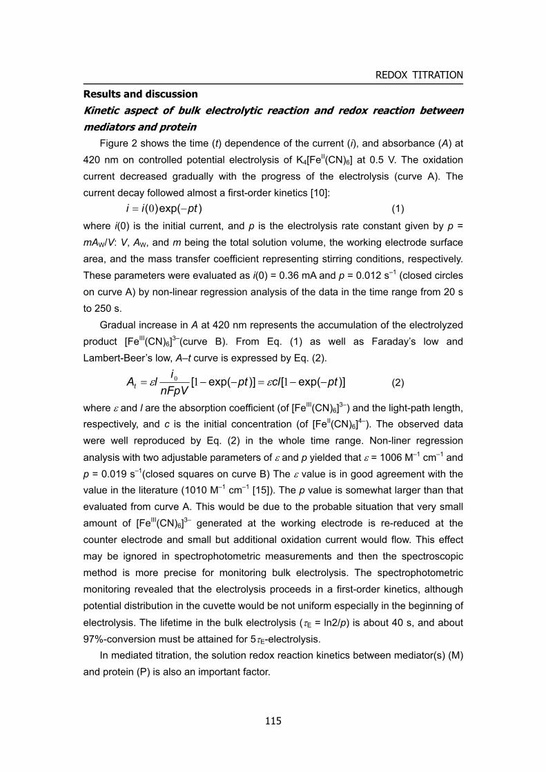
REDOX TITRATION
Results and discussion
Kinetic aspect of bulk electrolytic reaction and redox reaction between mediators and protein
Figure 2 shows the time (t) dependence of the current (i), and absorbance (A) at 420 nm on controlled potential electrolysis of K4[FeII(CN)6] at 0.5 V. The oxidation current decreased gradually with the progress of the electrolysis (curve A). The current decay followed almost a first-order kinetics [10]:
)exp()( ptii −= 0 (1)
where i(0) is the initial current, and p is the electrolysis rate constant given by p = mAW/V: V, AW, and m being the total solution volume, the working electrode surface area, and the mass transfer coefficient representing stirring conditions, respectively. These parameters were evaluated as i(0) = 0.36 mA and p = 0.012 s–1 (closed circles on curve A) by non-linear regression analysis of the data in the time range from 20 s to 250 s.
Gradual increase in A at 420 nm represents the accumulation of the electrolyzed product [FeIII(CN)6]3–(curve B). From Eq. (1) as well as Faraday’s low and Lambert-Beer’s low, A–t curve is expressed by Eq. (2).
)]exp([)]exp([ ptclptnFpV
ilAt −−=−−= 110 εε (2)
where ε and l are the absorption coefficient (of [FeIII(CN)6]3–) and the light-path length, respectively, and c is the initial concentration (of [FeII(CN)6]4–). The observed data were well reproduced by Eq. (2) in the whole time range. Non-liner regression
analysis with two adjustable parameters of ε and p yielded that ε = 1006 M–1 cm–1 and p = 0.019 s–1(closed squares on curve B) The ε value is in good agreement with the value in the literature (1010 M–1 cm–1 [15]). The p value is somewhat larger than that evaluated from curve A. This would be due to the probable situation that very small amount of [FeIII(CN)6]3– generated at the working electrode is re-reduced at the counter electrode and small but additional oxidation current would flow. This effect may be ignored in spectrophotometric measurements and then the spectroscopic method is more precise for monitoring bulk electrolysis. The spectrophotometric monitoring revealed that the electrolysis proceeds in a first-order kinetics, although potential distribution in the cuvette would be not uniform especially in the beginning of
electrolysis. The lifetime in the bulk electrolysis (τE = ln2/p) is about 40 s, and about 97%-conversion must be attained for 5τE-electrolysis.
In mediated titration, the solution redox reaction kinetics between mediator(s) (M) and protein (P) is also an important factor.
115
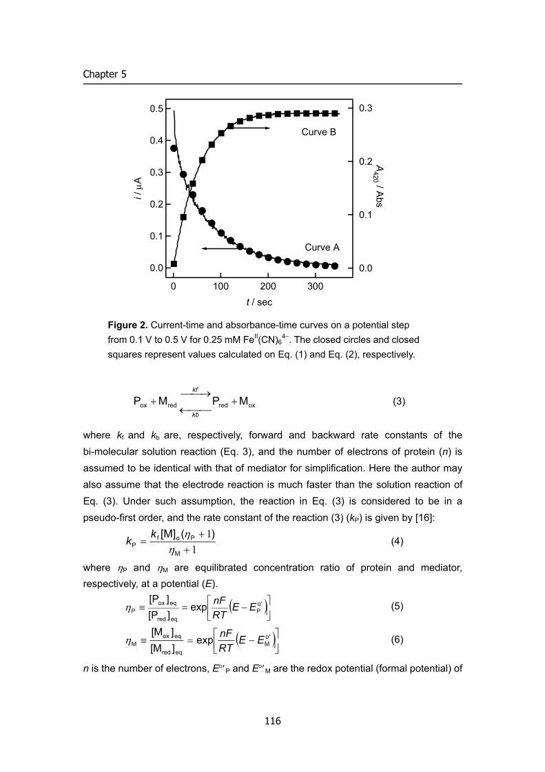
Chapter 5
0.5
0.4
0.3
0.2
0.1
0.0
i / μ
A
3002001000t / sec
0.3
0.2
0.1
0.0
A420 / Abs
Curve A
Curve B
Figure 2. Current-time and absorbance-time curves on a potential step from 0.1 V to 0.5 V for 0.25 mM FeII(CN)6
4–. The closed circles and closed squares represent values calculated on Eq. (1) and Eq. (2), respectively.
oxredredox MPMP +⎯⎯←⎯→⎯
+kb
kf
(3)
where kf and kb are, respectively, forward and backward rate constants of the bi-molecular solution reaction (Eq. 3), and the number of electrons of protein (n) is assumed to be identical with that of mediator for simplification. Here the author may also assume that the electrode reaction is much faster than the solution reaction of Eq. (3). Under such assumption, the reaction in Eq. (3) is considered to be in a pseudo-first order, and the rate constant of the reaction (3) (kP) is given by [16]:
11
++
=M
PofP
)([M]η
ηkk (4)
where ηP and ηM are equilibrated concentration ratio of protein and mediator, respectively, at a potential (E).
( ⎥⎦⎤
⎢⎣⎡ −=≡ 'o
Peqred
eqoxP exp
][P][P
EERTnFη ) (5)
( ⎥⎦⎤
⎢⎣⎡ −=≡ 'o
Meqred
eqoxM exp
]M[]M[
EERTnFη ) (6)
n is the number of electrons, E°′P and E°′M are the redox potential (formal potential) of
116
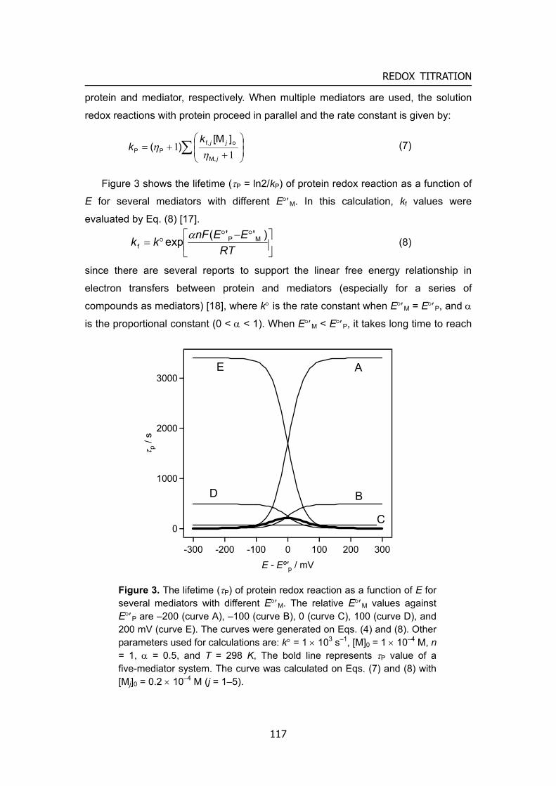
REDOX TITRATION
protein and mediator, respectively. When multiple mediators are used, the solution
redox reactions with protein proceed in parallel and the rate constant is given by:
∑ ⎟⎟⎠
⎞⎜⎜⎝
⎛
++=
11
j
jjkk
M,
of,PP
]M[)(
ηη (7)
Figure 3 shows the lifetime (τP = ln2/kP) of protein redox reaction as a function of
E for several mediators with different E°′M. In this calculation, kf values were
evaluated by Eq. (8) [17].
⎥⎦
⎤⎢⎣
⎡ °−°°=
RTEEnFkk )''(exp MP
fα
(8)
since there are several reports to support the linear free energy relationship in
electron transfers between protein and mediators (especially for a series of
compounds as mediators) [18], where k° is the rate constant when E°′M = E°′P, and α
is the proportional constant (0 < α < 1). When E°′M < E°′P, it takes long time to reach
3000
2000
1000
0
τ p /
s
A
B
C
-300 -200 -100 0 100 200 300E - Eº'p / mV
D
E
Figure 3. The lifetime (τP) of protein redox reaction as a function of E for several mediators with different E°′M. The relative E°′M values against E°′P are –200 (curve A), –100 (curve B), 0 (curve C), 100 (curve D), and 200 mV (curve E). The curves were generated on Eqs. (4) and (8). Other parameters used for calculations are: k° = 1 × 10³ s–1, [M]0 = 1 × 10⁻⁴ M, n = 1, α = 0.5, and T = 298 K, The bold line represents τP value of a five-mediator system. The curve was calculated on Eqs. (7) and (8) with [Mj]0 = 0.2 × 10⁻⁴ M (j = 1–5).
117
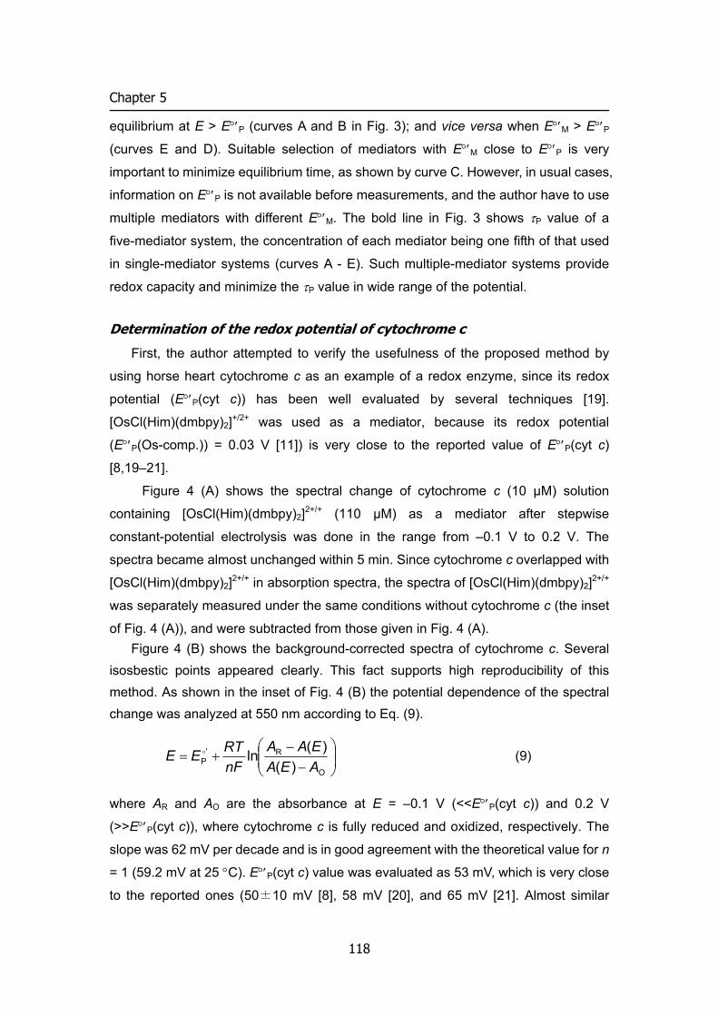
Chapter 5
equilibrium at E > E°′P (curves A and B in Fig. 3); and vice versa when E°′M > E°′P
(curves E and D). Suitable selection of mediators with E°′M close to E°′P is very
important to minimize equilibrium time, as shown by curve C. However, in usual cases,
information on E°′P is not available before measurements, and the author have to use
multiple mediators with different E°′M. The bold line in Fig. 3 shows τP value of a
five-mediator system, the concentration of each mediator being one fifth of that used
in single-mediator systems (curves A - E). Such multiple-mediator systems provide
redox capacity and minimize the τP value in wide range of the potential.
Determination of the redox potential of cytochrome c
First, the author attempted to verify the usefulness of the proposed method by
using horse heart cytochrome c as an example of a redox enzyme, since its redox
potential (E°′P(cyt c)) has been well evaluated by several techniques [19].
[OsCl(Him)(dmbpy)2]+/2+ was used as a mediator, because its redox potential
(E°′P(Os-comp.)) = 0.03 V [11]) is very close to the reported value of E°′P(cyt c)
[8,19–21].
Figure 4 (A) shows the spectral change of cytochrome c (10 μM) solution
containing [OsCl(Him)(dmbpy)2]2+/+ (110 μM) as a mediator after stepwise
constant-potential electrolysis was done in the range from –0.1 V to 0.2 V. The
spectra became almost unchanged within 5 min. Since cytochrome c overlapped with
[OsCl(Him)(dmbpy)2]2+/+ in absorption spectra, the spectra of [OsCl(Him)(dmbpy)2]2+/+
was separately measured under the same conditions without cytochrome c (the inset
of Fig. 4 (A)), and were subtracted from those given in Fig. 4 (A). Figure 4 (B) shows the background-corrected spectra of cytochrome c. Several
isosbestic points appeared clearly. This fact supports high reproducibility of this method. As shown in the inset of Fig. 4 (B) the potential dependence of the spectral change was analyzed at 550 nm according to Eq. (9).
⎟⎟⎠
⎞⎜⎜⎝
⎛−
−+=
O
R'P )(
)(lnAEAEAA
nFRTEE o (9)
where AR and AO are the absorbance at E = –0.1 V (<<E°′P(cyt c)) and 0.2 V
(>>E°′P(cyt c)), where cytochrome c is fully reduced and oxidized, respectively. The
slope was 62 mV per decade and is in good agreement with the theoretical value for n
= 1 (59.2 mV at 25 °C). E°′P(cyt c) value was evaluated as 53 mV, which is very close
to the reported ones (50±10 mV [8], 58 mV [20], and 65 mV [21]. Almost similar
118
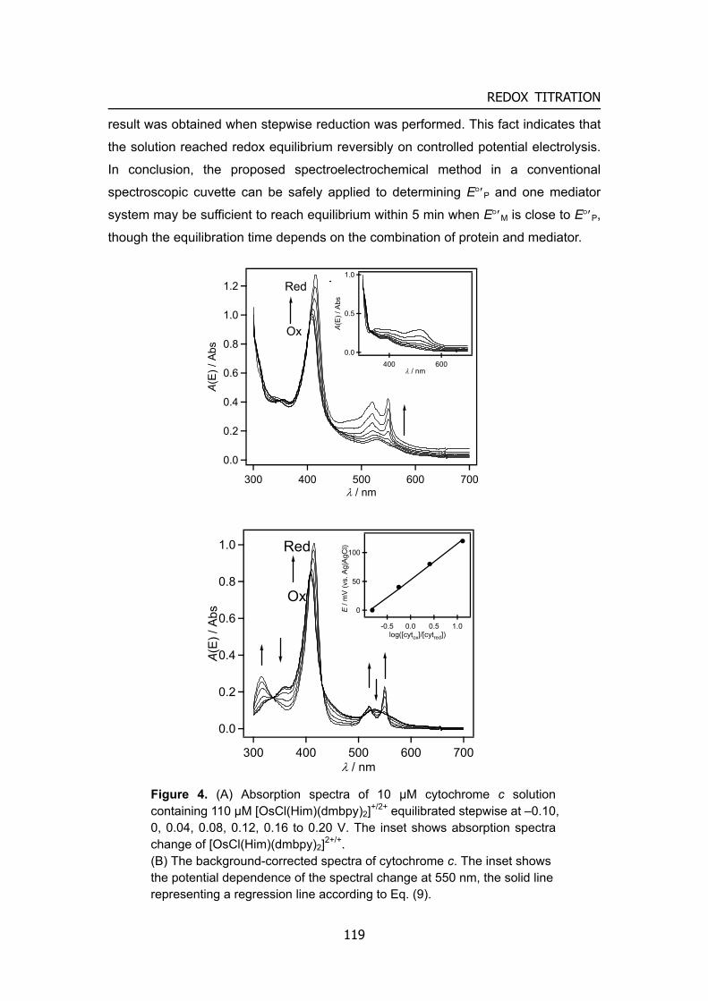
REDOX TITRATION
result was obtained when stepwise reduction was performed. This fact indicates that
the solution reached redox equilibrium reversibly on controlled potential electrolysis.
In conclusion, the proposed spectroelectrochemical method in a conventional
spectroscopic cuvette can be safely applied to determining E°′P and one mediator
system may be sufficient to reach equilibrium within 5 min when E°′M is close to E°′P,
though the equilibration time depends on the combination of protein and mediator.
1.2
1.0
0.8
0.6
0.4
0.2
0.0
A(E
) / A
bs
700600500400300λ / nm
Red
Ox
1.0
0.5
0.0
A(E
) / A
bs
600400λ / nm
1.0
0.8
0.6
0.4
0.2
0.0
A(E
) / A
bs
700600500400300λ / nm
Red
Ox
100
50
0E /
mV
(vs.
Ag|
AgC
l)
1.00.50.0-0.5log([cytox]/[cytred])
Figure 4. (A) Absorption spectra of 10 μM cytochrome c solution containing 110 μM [OsCl(Him)(dmbpy)2]+/2+ equilibrated stepwise at –0.10, 0, 0.04, 0.08, 0.12, 0.16 to 0.20 V. The inset shows absorption spectra change of [OsCl(Him)(dmbpy)2]2+/+. (B) The background-corrected spectra of cytochrome c. The inset shows the potential dependence of the spectral change at 550 nm, the solid line representing a regression line according to Eq. (9).
119
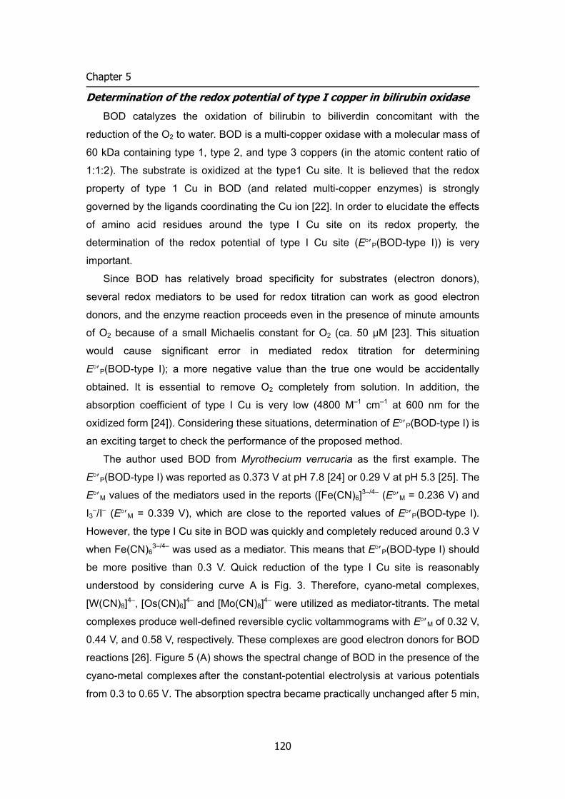
Chapter 5
Determination of the redox potential of type I copper in bilirubin oxidase
BOD catalyzes the oxidation of bilirubin to biliverdin concomitant with the
reduction of the O2 to water. BOD is a multi-copper oxidase with a molecular mass of
60 kDa containing type 1, type 2, and type 3 coppers (in the atomic content ratio of
1:1:2). The substrate is oxidized at the type1 Cu site. It is believed that the redox
property of type 1 Cu in BOD (and related multi-copper enzymes) is strongly
governed by the ligands coordinating the Cu ion [22]. In order to elucidate the effects
of amino acid residues around the type I Cu site on its redox property, the
determination of the redox potential of type I Cu site (E°′P(BOD-type I)) is very
important.
Since BOD has relatively broad specificity for substrates (electron donors),
several redox mediators to be used for redox titration can work as good electron
donors, and the enzyme reaction proceeds even in the presence of minute amounts
of O2 because of a small Michaelis constant for O2 (ca. 50 µM [23]. This situation
would cause significant error in mediated redox titration for determining
E°′P(BOD-type I); a more negative value than the true one would be accidentally
obtained. It is essential to remove O2 completely from solution. In addition, the
absorption coefficient of type I Cu is very low (4800 M–1 cm–1 at 600 nm for the
oxidized form [24]). Considering these situations, determination of E°′P(BOD-type I) is
an exciting target to check the performance of the proposed method.
The author used BOD from Myrothecium verrucaria as the first example. The
E°′P(BOD-type I) was reported as 0.373 V at pH 7.8 [24] or 0.29 V at pH 5.3 [25]. The
E°′M values of the mediators used in the reports ([Fe(CN)6]3–/4– (E°′M = 0.236 V) and
I3–/I– (E°′M = 0.339 V), which are close to the reported values of E°′P(BOD-type I).
However, the type I Cu site in BOD was quickly and completely reduced around 0.3 V
when Fe(CN)63–/4– was used as a mediator. This means that E°′P(BOD-type I) should
be more positive than 0.3 V. Quick reduction of the type I Cu site is reasonably
understood by considering curve A is Fig. 3. Therefore, cyano-metal complexes,
[W(CN)8]4–, [Os(CN)6]4– and [Mo(CN)8]4– were utilized as mediator-titrants. The metal
complexes produce well-defined reversible cyclic voltammograms with E°′M of 0.32 V,
0.44 V, and 0.58 V, respectively. These complexes are good electron donors for BOD
reactions [26]. Figure 5 (A) shows the spectral change of BOD in the presence of the
cyano-metal complexes after the constant-potential electrolysis at various potentials
from 0.3 to 0.65 V. The absorption spectra became practically unchanged after 5 min,
120
REDOX TITRATION
but electrolysis continued for 10 min. The increase in absorbance around 600 nm
reflects the oxidation of type 1 Cu site in BOD.
Since both oxidized and reduced state of the cyano-metal complexes used do not
adsorb the light in the wavelength region from 500 to 750 nm, the potential
dependence of the absorbance at 600 nm was analyzed without background
subtraction, by using Eq. (9). As shown in Figure 5 (B), a good linear relation was
obtained in the Nernstian analysis. The slope is 83 mV, which is somewhat larger
0.55
0.50
0.45
0.40
0.35
E /
V (v
s. A
g|A
gCl)
-2 -1 0 1 2log (BODox/BODred)
0.15
0.10
0.05
0.00
A(E
) / A
bs
650600550500λ / nm
0.3 V
0.65 V
Figure 5. (A) The absorption spectra of BOD from Myrothecium verrucaria in the presence of the cyano-metal complexes after constant-potential electrolysis at 0.30, 0.34, 0.38, 0.42, 0.44, 0.46, 0.48, 0.50, 0.53, 0.57, 0.65 V. (B) Nernstian plots of E dependence of the absorbance at 600 nm. The solid line represents a regression line according to Eq. (9).
121
Chapter 5
than the theoretical one for n = 1. The disagreement might be in part attributable to
(very small) spectral change of type 2-3 Cu cluster due to its redox reaction. The
value of E°′P(BOD-type I) was evaluated from the plot as 0.46 V. This value is located
in high redox buffer capacity region provided by [W(CN)8]4–, [Os(CN)6]4– and
[Mo(CN)8]4–. In addition, BOD gives bioelectrocatalytic wave of O2 reduction owing to
direct electron transfer from some carbon electrodes to oxidized BOD, and the
catalytic wave has been well explained by considering this E°′P(BOD-type I) value
[27,28]. Therefore, the author believes that the present value is reliable. In the
literature [24,25], the E°′M values of the mediators used are more negative than the
E°′P(BOD-type I) value evaluated here. As shown in Fig. 3 (curves A and B)), it would
take extremely long time to reach equilibration in the potential region around and
more positive than E°′P when E°′M < E°′P. In such cases, more negative values might
be erroneously obtained [29]. The author also attempted to determine E°′P(BOD-type
I) of BOD from Trachderma tsunodae, which was evaluated as 0.510 V at pH 7.0. The
values evaluated here were also more positive than the reported one (0.415 V at pH
6.8 [30]). When evaluated E°′P values are out of redox capacity regions in
mediator-assisted methods, it would be very important to re-evaluate E°′P by using
more suitable mediator(s).
Concluding remarks The mediator-assisted separator-less one-compartment bulk electrolysis method
is a novel technique for indirect spectroelectrochemical titration of proteins. Since conventional spectroscopic cuvettes can be used as electrolysis cells, no special instruments are required except potentiostat and spectrophotometer. The method has high reproducibility, and the subtraction of the background due to mediator adsorption is very easy. In addition, it is not difficult to remove O2 from the cell. Low absorbance samples (of low concentrations or low absorption coefficients) are also acceptable for measurements. Actually, this method has been successfully applied to more complicated examples such as multi-heme proteins and membrane bound proteins. Details will be reported elsewhere in combination with biochemical interests. The author hopes this method is of great benefit for many researchers in the fields of biochemistry and electrochemistry.
122
REDOX TITRATION
References
[1] F.A. Armstrong, H.A.O. Hill, N.J. Walton, Acc. Chem. Res., 21, 407 (1988). [2] G.S. Wilson, S. Fleischer and L. Packer (Eds.), Methods in Enzymology,
Academic Press, New York, vol. 58, pp. 396–410 (1978). [3] P.L. Dutton, S. Fleischer and L. Packer (Eds.), Methods in Enzymology, Academic
Press, New York, vol. 58, pp. 411–435 (1978). [4] W.R. Heineman, F.M. Hawkridge, H.N. Blount, A. J. Bard (Ed.), Electroanalytical
Chemistry, Marcel Dekker, New York, vol. 13, pp 1–113 (1984). [5] S. Dong, J. Niu, T.M. Cotton, Methods in Enzymology, Academic Press, New York,
vol. 246, pp. 701–32 (1995). [6] M. Torimura, M. Mochizuki, K. Kano, T. Ikeda, T. Ueda, Anal. Chem., 70, 4690
(1998). [7] M. Torimura, K. Kano, T. Ikeda, T. Ueda, Chem. Lett., 525 (1997). [8] M. Oyama, M. Okada, S. Okazaki, Denki Kagaku, 61, 778 (1993). [9] T. Larsson, A. Lindgren, T. Ruzgas, Bioelectrochem., 53, 243 (2001). [10] A. Kuriyama, M. Arasaki, N. Fujieda, S. Tsujimura, K. Kano, T. Ikeda,
Electrochemistry, 72, 484 (2004). [11] Y. Nakabayashi, A. Omayu, S. Yagi, K. Nakamura, J. Motonaka, Anal. Sci., 17,
945 (2001). [12] J.G. Leipoldt, L.D.C. Bok, P.J. Cilliers, Z. Anorg. Allg. Chem., 407, 350 (1974). [13] J.C. Curtis, T. J. Meyer, Inorg. Chem., 21, 1562 (1982). [14] J.G. Leipoldt, L.D.C. Bok, P.J. Cillers, Z. Anorg. Allg. Chem., 409, 3433 (1974). [15] S. Kida (Ed.), Jikken Kagaku Kouza vol. 17, Maruzen, Tokyo, Japan, p. 89 (1991)
(in Japanese). [16] A. Sato, M. Torimura, K. Takagi, K. Kano, T. Ikeda, Anal. Chem., 72, 150 (2000). [17] K. Takagi, K. Kano, T. Ikeda, J. Electroanal. Chem., 445, 211 (1998). [18] J.J. Kulys, N.K. Cenas, Biochim. Biophys. Acta, 744, 57 (1983). [19] K. Kano, Rev. Polarogr., 48, 29 (2002). [20] M.J. Eddowes, H.A.O. Hill, J. Am. Chem. Soc., 101, 4461 (1979). [21] W.R. Heineman, B.J. Norris, J.F. Goelz, Anal. Chem., 47, 79 (1975). [22] F. Xu, R.M.Berka, J.A. Wahleithner, B.A. Nelson, J.R. Shuster, S.H. Brown, A.E.
Palmer, E.I. Solomon, Biochem. J., 334, 63 (1998). [23] S. Tsujimura, H. Tatsumi, J. Ogawa, S. Shimizu, K. Kano, T. Ikeda, J. Electroanal.
Chem., 496, 69 (2001). [24] A. Shimizu, T. Sasaki, J.H. Kwon, A. Odaka, T. Satoh, N. Sakurai, T. Sakurai, S.
Yamaguchi, T. Samejima, J. Biochem., 125, 662 (1999).
123
Chapter 5
124
[25] F. Xu, W. Shin, S.H. Brown, J.A. Wahleithner, U.M. Sundaram, E.I. Solomon, Biochim. Biophys. Acta, 1292, 303 (1996).
[26] S. Tsujimura, M. Kawaharada, T. Nakagawa, K. Kano, T. Ikeda, Electrochem.
Commun., 5, 138 (2003). [27] S. Tsujimura, T. Nakagawa, K. Kano, T. Ikeda, Electrochemistry, 72, 437 (2004). [28] S. Tsujimura, K. Kano, T. Ikeda, J. Electroanal. Chem., 576, 113 (2005) [29] K. Kano, T. Ikeda, Anal. Sci., 16, 1013 (2000). [30] J. Hirose, K. Inoue, H. Sakuragi, M. Kikkawa, M. Minakami, T. Morikawa, H.
Iwamoto, K. Hiromi, Inorg. Chim. Acta, 273, 204 (1998).
Appendix A
Theory of bioelectrocatalytic current The enzyme-catalyzed electrochemical reaction, called bioelectrocatalysis, is classified
into direct electron transfer system and mediated electron transfer system.
Fundamental properties and theoretical equations of steady-state catalytic current and
current-potential curve of both systems are summarized.
1 Introduction
Oxidoreductases are a group of enzymes catalyzing biological redox reactions and have received considerable attention in connecting their reactions with electrochemical reactions, since the connection has been expected to open a new one for applying the enzymes in a variety of field. Enzymes have novel properties of substrate specificities and high catalytic efficiencies, allowing each of them to function in a specific biological reaction under such mild reaction conditions as atmospheric pressure, temperature around 20 to 40 ºC, and pH near neutrality. “Bioelectrocatalysis” is the term expressing the enzyme-catalyzed acceleration of electrochemical reactions of substrates. Bioelectrocatalysis is now recognized as a key reaction for developing not only biosensor but also bioreactor and biofuel cells and also for understanding the kinetics and thermodynamics of oxidoreductase reactions [1, 2]. A great number of researches have appeared dealing with bioelectrocatalysis with emphasis on the applied aspect, especially of the second-generation amperometric biosensors.
The most oxidoreductase reaction (except for the NAD-dependant oxidoreductase reaction) obeys the “ping-pong” mechanism. In this paper, the author would describe the reaction of substrate (S) oxidation.
Reduced substrate (S) is oxidized by oxidized enzyme (Eox) and reduced enzyme (Ered) transfer electron to the electron acceptor (EA). These reactions are usually
125
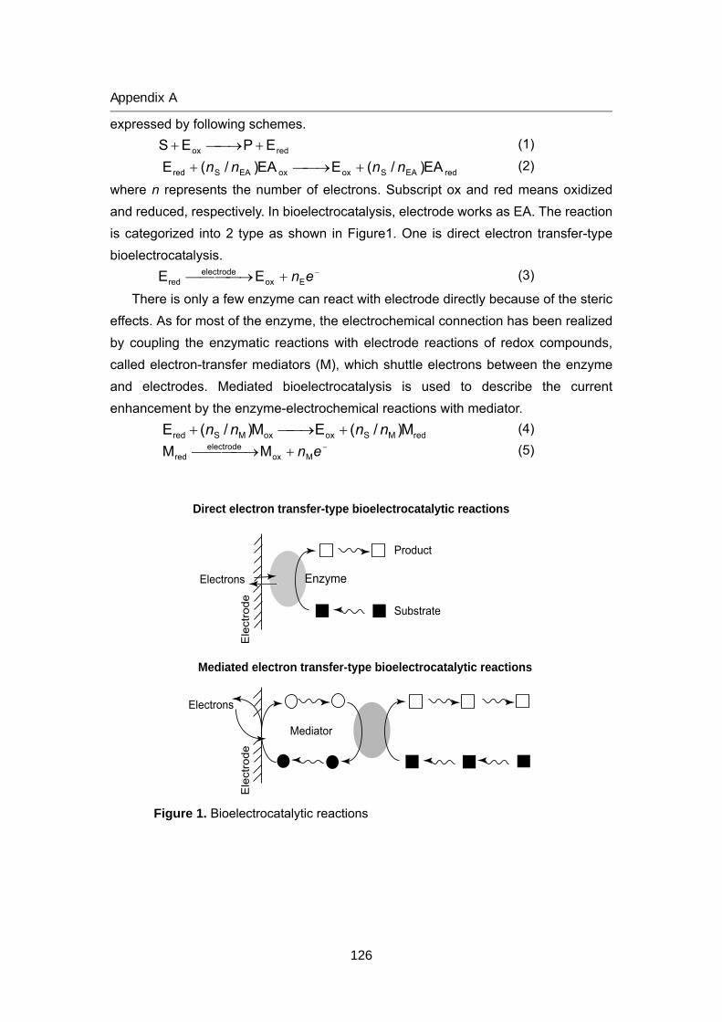
Appendix A
expressed by following schemes.
redox EPES +⎯→⎯+ (1)
redEASoxoxEASred EA)/(EEA)/(E nnnn +⎯→⎯+ (2)
where n represents the number of electrons. Subscript ox and red means oxidized and reduced, respectively. In bioelectrocatalysis, electrode works as EA. The reaction is categorized into 2 type as shown in Figure1. One is direct electron transfer-type bioelectrocatalysis.
−+⎯⎯⎯ →⎯ enEoxelectrode
red EE (3)
There is only a few enzyme can react with electrode directly because of the steric effects. As for most of the enzyme, the electrochemical connection has been realized by coupling the enzymatic reactions with electrode reactions of redox compounds, called electron-transfer mediators (M), which shuttle electrons between the enzyme and electrodes. Mediated bioelectrocatalysis is used to describe the current enhancement by the enzyme-electrochemical reactions with mediator.
redMSoxoxMSred M)/(EM)/(E nnnn +⎯→⎯+ (4) −+⎯⎯⎯ →⎯ enMox
electrodered MM (5)
Mediated electron transfer-type bioelectrocatalytic reactions
Direct electron transfer-type bioelectrocatalytic reactions
Electrons
Ele
ctro
deE
lect
rode
Electrons
Mediator
Substrate
Enzyme
Product
Figure 1. Bioelectrocatalytic reactions
126
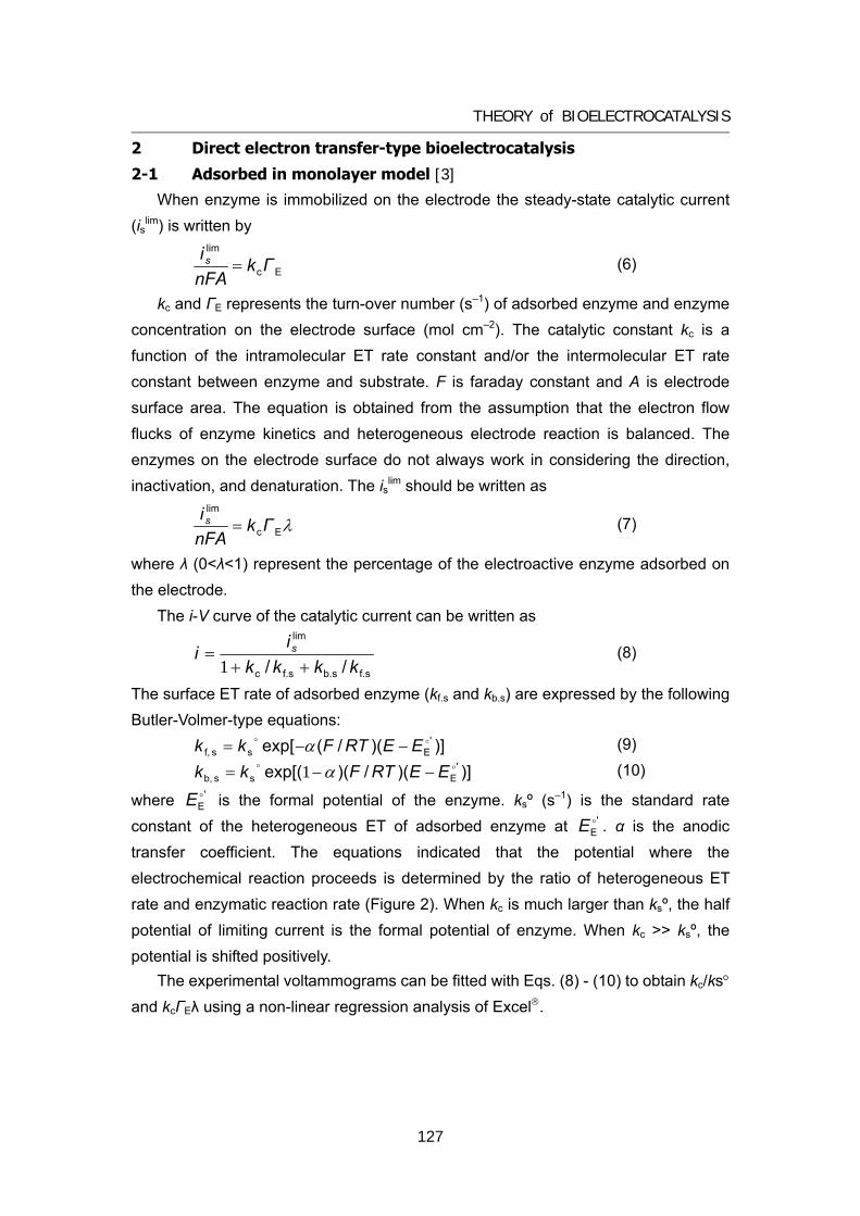
THEORY of BIOELECTROCATALYSIS
2 Direct electron transfer-type bioelectrocatalysis
2-1 Adsorbed in monolayer model [3]
When enzyme is immobilized on the electrode the steady-state catalytic current (islim) is written by
Ec
lim
ΓknFAis = (6)
kc and ΓE represents the turn-over number (s–1) of adsorbed enzyme and enzyme concentration on the electrode surface (mol cm–2). The catalytic constant kc is a function of the intramolecular ET rate constant and/or the intermolecular ET rate constant between enzyme and substrate. F is faraday constant and A is electrode surface area. The equation is obtained from the assumption that the electron flow flucks of enzyme kinetics and heterogeneous electrode reaction is balanced. The enzymes on the electrode surface do not always work in considering the direction, inactivation, and denaturation. The islim should be written as
λEc
lim
ΓknFAis = (7)
where λ (0<λ<1) represent the percentage of the electroactive enzyme adsorbed on the electrode.
The i-V curve of the catalytic current can be written as
f.sb.sf.sc
lim
// kkkkii s
++=
1 (8)
The surface ET rate of adsorbed enzyme (kf.s and kb.s) are expressed by the following Butler-Volmer-type equations:
)])(/(exp[ 'Ess f,oo EERTFkk −−= α (9)
)])(/)(exp[( 'Ess b,oo EERTFkk −−= α1 (10)
where is the formal potential of the enzyme. ksº (s–1) is the standard rate constant of the heterogeneous ET of adsorbed enzyme at . α is the anodic transfer coefficient. The equations indicated that the potential where the electrochemical reaction proceeds is determined by the ratio of heterogeneous ET rate and enzymatic reaction rate (Figure 2). When kc is much larger than ksº, the half potential of limiting current is the formal potential of enzyme. When kc >> ksº, the potential is shifted positively.
'EoE
'EoE
The experimental voltammograms can be fitted with Eqs. (8) - (10) to obtain kc/ks° and kcΓEλ using a non-linear regression analysis of Excel®.
127
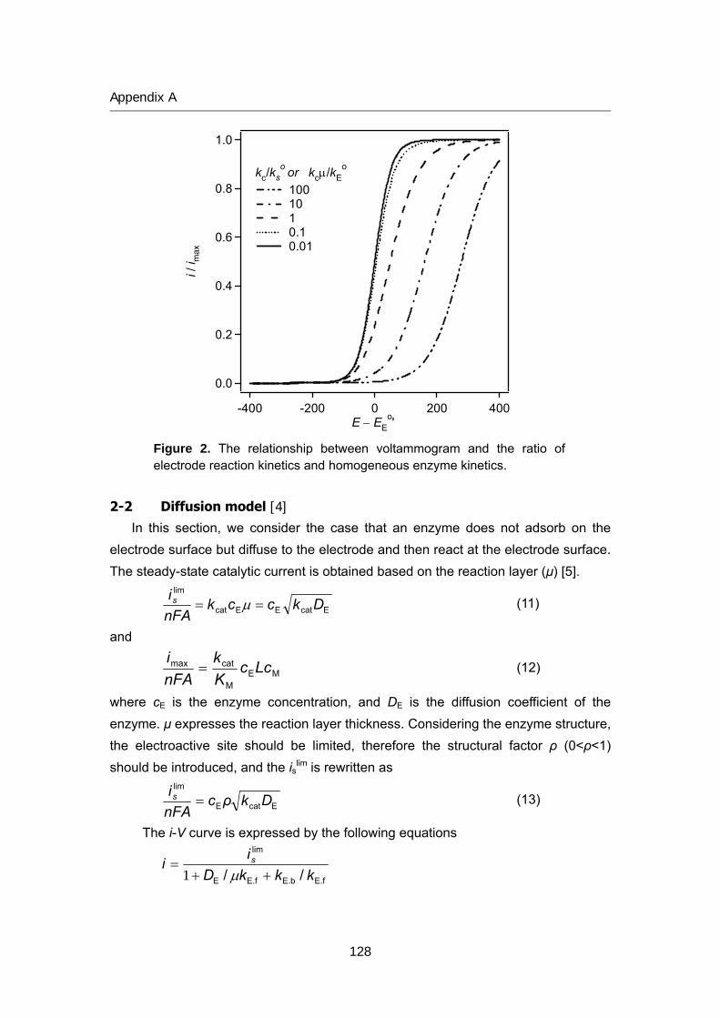
Appendix A
1.0
0.8
0.6
0.4
0.2
0.0
i / i m
ax
-400 -200 0 200 400E − EE
o'
kc/kso or kcμ/kE
o 100 10 1 0.1 0.01
Figure 2. The relationship between voltammogram and the ratio of electrode reaction kinetics and homogeneous enzyme kinetics.
2-2 Diffusion model [4] In this section, we consider the case that an enzyme does not adsorb on the
electrode surface but diffuse to the electrode and then react at the electrode surface. The steady-state catalytic current is obtained based on the reaction layer (μ) [5].
EcatEEcat
lim
DkccknFAis == μ (11)
and
MEM
catmax LccKk
nFAi
= (12)
where cE is the enzyme concentration, and DE is the diffusion coefficient of the enzyme. μ expresses the reaction layer thickness. Considering the enzyme structure, the electroactive site should be limited, therefore the structural factor ρ (0<ρ<1) should be introduced, and the islim is rewritten as
EcatE
lim
DkρcnFAis = (13)
The i-V curve is expressed by the following equations
E.fE.bE.fE
lim
// kkkDii s
++=
μ1
128
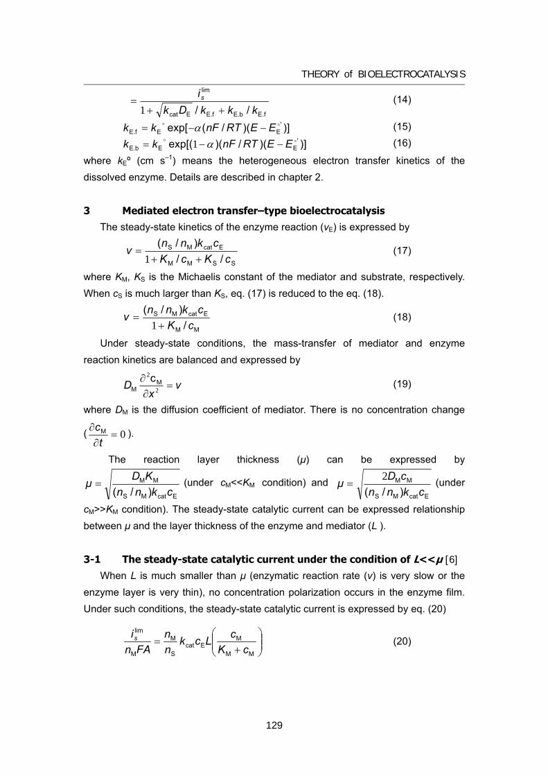
THEORY of BIOELECTROCATALYSIS
E.fE.bE.fEcat
lim
// kkkDkis
++=
1 (14)
)])(/(exp[ 'EEE.foo EERTnFkk −−= α (15)
)])(/)(exp[( 'EEE.boo EERTnFkk −−= α1 (16)
where kEº (cm s–1) means the heterogeneous electron transfer kinetics of the dissolved enzyme. Details are described in chapter 2.
3 Mediated electron transfer–type bioelectrocatalysis
The steady-state kinetics of the enzyme reaction (vE) is expressed by
SSMM
EcatMS
//)/(
cKcKcknn
v++
=1
(17)
where KM, KS is the Michaelis constant of the mediator and substrate, respectively. When cS is much larger than KS, eq. (17) is reduced to the eq. (18).
MM
EcatMS
/)/(
cKcknnv
+=
1 (18)
Under steady-state conditions, the mass-transfer of mediator and enzyme reaction kinetics are balanced and expressed by
vx
D =∂∂
2
2M
Mc (19)
where DM is the diffusion coefficient of mediator. There is no concentration change
( 0=∂∂
tcM ).
The reaction layer thickness (μ) can be expressed by
EcatMS
MM
)/( cknnKDμ = (under cM<<KM condition) and
EcatMS
MM
)/( cknncDμ 2
= (under
cM>>KM condition). The steady-state catalytic current can be expressed relationship between μ and the layer thickness of the enzyme and mediator (L ).
3-1 The steady-state catalytic current under the condition of L<<μ [6]
When L is much smaller than μ (enzymatic reaction rate (v) is very slow or the enzyme layer is very thin), no concentration polarization occurs in the enzyme film. Under such conditions, the steady-state catalytic current is expressed by eq. (20)
⎟⎟⎠
⎞⎜⎜⎝
⎛+
=MM
MEcat
S
M
M
lim
cKcLck
nn
FAnis (20)
129
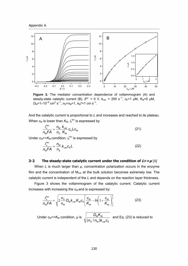
Appendix A
12
10
8
6
4
2
0
i / μ
A
-0.3 -0.2 -0.1 0.0 0.1 0.2 0.3E / V
12
10
8
6
4
2
0
i / μ
A
50403020100cM / μM
1.5
1.0
0.5
0.0
i / μ
A
3210cM / μM
A B
Figure 3. The mediator concentration dependence of voltammogram (A) and steady-state catalytic current (B). Eº´ = 0 V, kcat = 200 s–1, cE=1 μM, KM=5 μM, DM=1×10⁻⁶ cm2 s–1, nS=nM=1, kMº=1 cm s–1.
And the catalytic current is proportional to L and increases and reached to its plateau. When cM is lower than KM, islim is expressed by
MEM
cat
S
M
M
lim
LccKk
nn
FAnis = (21)
Under cM>>KM condition, islim is expressed by
Lcknn
FAnis
EcatS
M
M
lim
= (22)
3-2 The steady-state catalytic current under the condition of L>>μ [6] When L is much larger than μ, concentration polarization occurs in the enzyme
film and the concentration of MOX at the bulk solution becomes extremely low. The catalytic current is independent of the L and depends on the reaction layer thickness.
Figure 3 shows the voltammogram of the catalytic current. Catalytic current increases with increasing the cM and is expressed by:
⎥⎦
⎤⎢⎣
⎡⎟⎟⎠
⎞⎜⎜⎝
⎛+−=
M
M
M
MEMM
M
S
M
lims ln
Kc
KccKkD
nn
FAnI
cat 12 (23)
Under c <<K condition, μ is M M
EcatMS
MM
)/( cknnKD and Eq. (23) is reduced to
130
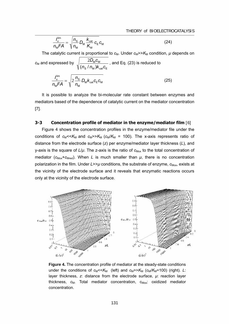
THEORY of BIOELECTROCATALYSIS
MEM
catM
M
S
M
lim
ccKkD
nn
FAnIs = ( 24)
The catalytic current is proportion on
cM and expressed by
al to cM. Under cM>>KM condition, μ depends
EcatMS )/( cknn
MMcD2 , and Eq. (23) is reduced to
MEcatMM
S
M
lim nI cckDnFAn
s 2= (25)
me
ratio of cMox to the total concentration of mediator (cMox+cMred). When L is much smaller than μ, there is no concentration polarization in the film. Under L>>μ conditions, the substrate of enzyme, cMox, exists at the vicinity of the electrode surface and it reveals that enzymatic reactions occurs only at the vicinity of the electrode surface.
It is possible to analyze the bi-molecular rate constant between enzymes anddiators based of the dependence of catalytic current on the mediator concentration
[7].
3-3 Concentration profile of mediator in the enzyme/mediator film [6] Figure 4 shows the concentration profiles in the enzyme/mediator file under the
conditions of cM<<KM and cM>>KM (cM/KM = 100). The x-axis represents ratio of distance from the electrode surface (z) per enzyme/mediator layer thickness (L), and y-axis is the square of L/μ. The z-axis is the
Figure 4. The concentration profile of mediator at the steady-state conditions under the conditions of cM<<KM (left) and cM>>KM (cM/KM=100) (right). L: layer thickness, z: distance from the electrode surface, μ: reaction layer thickness, cM. Total mediator concentration, cMox: oxidized mediator concentration.
131
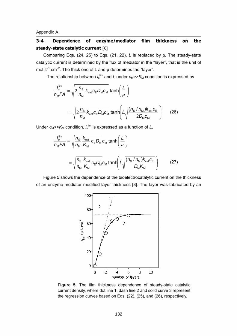
Appendix A
3-4 Dependence of enzyme/mediator film thickness on the
steady-state catalytic current [6]
Comparing Eqs. (24, 25) to Eqs. (21, 22), L is replaced by μ. The steady-state catalytic current is determined by the flux of mediator in the “layer”, that is the unit of mol s–1 cm–2. The thick one of L and μ determines the “layer”.
The relationship between islim and L under cM>>KM condition is expressed by
⎟⎟⎠
⎞⎜⎜⎝
⎛=
μLcDck
nn
FAnIs tanhMMEcat
M
S
M
lim
2
⎟⎟⎠
⎞⎜⎜⎝
⎛=
MM
EcatMSMMEcat
M
S )/(tanhcD
cknnLcDcknn
22 (26)
Under cM<<KM condition, islim is expressed as a function of L,
⎟⎟⎠
⎞⎜⎜⎝
⎛=
μLcDc
Kk
nn
FAnIs tanhMME
M
cat
M
S
M
lim
⎟⎟⎠
⎞⎜⎜⎝
⎛=
MM
EcatMSMME
M
cat
M
S )/(tanh
KDcknn
LcDcKk
nn (27)
Figure 5 shows the dependence of the bioelectrocatalytic current on the thickness of an enzyme-mediator modified layer thickness [8]. The layer was fabricated by an
Figure 5. The film thickness dependence of steady-state catalytic current density, where dot line 1, dash line 2 and solid curve 3 represent the regression curves based on Eqs. (22), (25), and (26), respectively.
132
THEORY of BIOELECTROCATALYSIS
electrostatic layer-by-layer assembly method. Positively charged enzyme (PQQ-dependant glucose dehydrogenase) and polymer-bounded mediator (Os com
hickness and reached satur he reaction layer with the enzymatic kinetic parameters, the concentrations of enzyme and mediator, and the diffusion coefficient of mediator.
3-5 Voltammograms of mediated bioelectrocatalysis [9-11] When the heterogeneous electron transfer reaction between mediator and
electrode is fast, so called “reversible”, the voltammogram is obtained by replacing
the cM to
plex-coordinated poly(N-vinylimidazole)) are successively entrapped on the electrode surface with the negatively charged polymer. The steady-state catalytic current value increased linearly with increasing the layer t
ated value. The behavior was successfully interpreted based on the theory of t
⎟⎟⎠
⎞⎜⎜⎝
⎛ η+ M
MM η
c1
(with ( )⎟⎠⎞
⎜⎝⎛ −=⎟
⎟⎠
⎞⎜⎜⎝
⎛=
=
'M
M
MM exp
red
ox oEERTc
η nFc
x 0
).
However, most of the case, the electrode reaction is categorize to “quasi-reversible”, thus it is not so fast that there is a time lag to reach a equilibrium of electrode potential and cM at the electrode surface. Under this urve is repressed by
condition, the i-V c
M.fM.bM.fM
lim
kkkDii s
++=
μ1 (28)
and
)])(/(exp[ 'MMM.foo EERTnFkk −−= α (29)
(30)
kMº is the heterogeneous ET rate constant of dissolved mediator. The voltammogram of mediated bioelectrocatalysis is very similar to that of DET reactions.
4 Concluding remarks This article describes the theory of steady-state bioelectrocatalytic current. The
steady-state catalytic current can be obtained at the condition cS is much higher than the Michaelis constant. Under the condition that the catalytic current depends on the substrate concentration, no-steady state catalytic current is observed on CVs. This is because the time-dependant substrate depression occurs at the vicinity of the electrode not observe wh iator
)])(/)(exp[( 'MMM.boo EERTnFkk −−= α1
surface, and no steady state is attained. Steady-state current canen scan rate is much higher than the enzymatic reaction rate, or med
133
Appendix A
134
] S. Tsujimura, K. Kano, and T. Ikeda, J. Electroanal. Chem., 576, 113 (2005). D rscience, NY,
[7] K. Kano, T. Ohgaru, H. Nakase, and T. Ikeda, Chem. Lett., 439 (1996). [8] A.
nd L. R. Faulkner, “Electrochemical Methods – Fundamentals and Applications”, Wiley, NY, 2001, Chap. 12.3.5
[11] J. M. Savéant and E. Vianello, Ele
concentration is high. In these conditions, the time-dependant diffusive current is dominant to enzymatic catalytic current.
4 References
[1] K. Kano and T. Ikeda, Anal. Sci., 16, 1013 (2000). [2] K. Kano and T. Ikeda, Electrochemistry, 71, 86 (2003). [3] S. Tsujimura, T. Nakagawa, K. Kano, and T. Ikeda, Electrochemistry, 72, 437
(2004). [4[5] P. elahay, New Instrumental Methods in Electrochemistry, Inte
1954; Reprint edn., Krieger, Huntington, NY, pp. 87-113 (1980). [6] W. J. Albery, A. E. G. Cass, and Z. X. Shu, Biosensors & Bioelectronics, 5, 367
(1990)
Ishii, S. Tsujimura, and K. Kano, Bunseki Kagaku, submitted. [9] Y. Ogino, K. Takagi, K. Kano, and T. Ikeda, J. Electroanal. Chem., 396, 517
(1995). [10] A. J. Bard a
ctrochim. Acta, 10, 905 (1965)
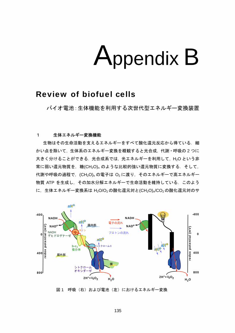
Appendix B
Review of biofuel cells
バイオ電池:生体機能を利用する次世代型エネルギー変換装置
1 生体エネルギー変換機能
生物はその生命活動を支えるエネルギーをすべて酸化還元反応から得ている.細
かい点を除いて,生体系のエネルギー変換を概観すると光合成,代謝・呼吸の 2 つに
大きく分けることができる.光合成系では,光エネルギーを利用して,H2O という非
常に弱い還元物質を,糖(CH2O)n のような比較的強い還元物質に変換する.そして,
代謝や呼吸の過程で,(CH2O)n の電子は O2 に渡り,そのエネルギーで高エネルギー
物質 ATP を生成し,その加水分解エネルギーで生命活動を維持している.このよう
に,生体エネルギー変換系は H2O/O2の酸化還元対と(CH2O)n/CO2の酸化還元対のサ
b-c1複合体
Q
シトクロームC
膜内部
膜
膜外部
NADHデヒドロゲナーゼ
red
ox
po
ten
tia
l (m
V)
0
800
-400
400
キノン
シトクロームオキシダーゼ
NADH
NAD+
2H++1/2O2 H2O
red
ox
po
ten
tia
l (m
V)
0
800
-400
400
電子の流れ
NADH
NAD+
2H++1/2O2 H2O
プロトンの流れ
図 1 呼吸(右)および電池(左)におけるエネルギー変換
135
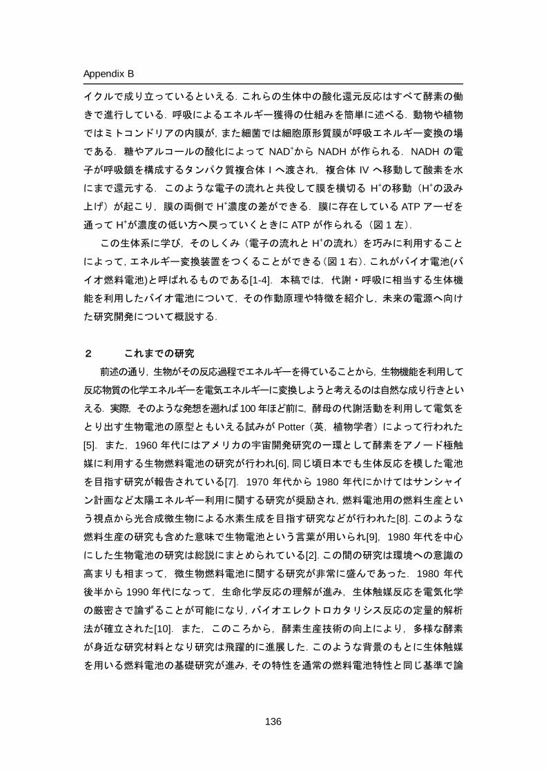
Appendix B
イクルで成り立っているといえる.これらの生体中の酸化還元反応はすべて酵素の働
きで進行している.呼吸によるエネルギー獲得の仕組みを簡単に述べる.動物や植物
ではミトコンドリアの内膜が,また細菌では細胞原形質膜が呼吸エネルギー変換の場
である.糖やアルコールの酸化によって NAD+から NADH が作られる.NADH の電
子が呼吸鎖を構成するタンパク質複合体 I へ渡され,複合体 IV へ移動して酸素を水
にまで還元する.このような電子の流れと共役して膜を横切る H+の移動(H+の汲み
上げ)が起こり,膜の両側で H+濃度の差ができる.膜に存在している ATP アーゼを
通って H+が濃度の低い方へ戻っていくときに ATP が作られる(図 1 左).
この生体系に学び,そのしくみ(電子の流れと H+の流れ)を巧みに利用すること
によって,エネルギー変換装置をつくることができる(図 1 右).これがバイオ電池(バ
イオ燃料電池)と呼ばれるものである[1-4].本稿では,代謝・呼吸に相当する生体機
能を利用したバイオ電池について,その作動原理や特徴を紹介し,未来の電源へ向け
た研究開発について概説する.
2 これまでの研究
前述の通り,生物がその反応過程でエネルギーを得ていることから,生物機能を利用して
反応物質の化学エネルギーを電気エネルギーに変換しようと考えるのは自然な成り行きとい
える.実際,そのような発想を遡れば100年ほど前に,酵母の代謝活動を利用して電気を
とり出す生物電池の原型ともいえる試みが Potter(英,植物学者)によって行われた
[5].また,1960 年代にはアメリカの宇宙開発研究の一環として酵素をアノード極触
媒に利用する生物燃料電池の研究が行われ[6],同じ頃日本でも生体反応を模した電池
を目指す研究が報告されている[7].1970 年代から 1980 年代にかけてはサンシャイ
ン計画など太陽エネルギー利用に関する研究が奨励され,燃料電池用の燃料生産とい
う視点から光合成微生物による水素生成を目指す研究などが行われた[8].このような
燃料生産の研究も含めた意味で生物電池という言葉が用いられ[9],1980 年代を中心
にした生物電池の研究は総説にまとめられている[2].この間の研究は環境への意識の
高まりも相まって,微生物燃料電池に関する研究が非常に盛んであった.1980 年代
後半から 1990 年代になって,生命化学反応の理解が進み,生体触媒反応を電気化学
の厳密さで論ずることが可能になり,バイオエレクトロカタリシス反応の定量的解析
法が確立された[10].また,このころから,酵素生産技術の向上により,多様な酵素
が身近な研究材料となり研究は飛躍的に進展した.このような背景のもとに生体触媒
を用いる燃料電池の基礎研究が進み,その特性を通常の燃料電池特性と同じ基準で論
136
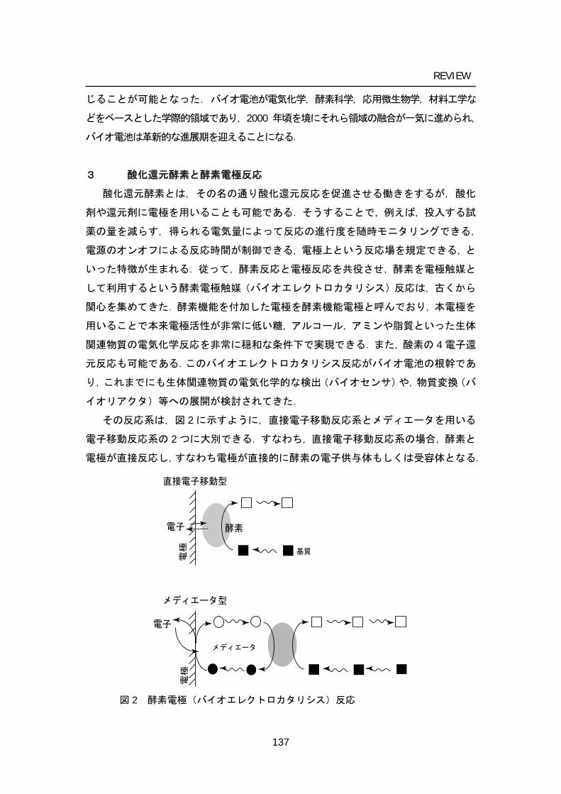
REVIEW
じることが可能となった.バイオ電池が電気化学,酵素科学,応用微生物学,材料工学な
どをベースとした学際的領域であり,2000 年頃を境にそれら領域の融合が一気に進められ,
バイオ電池は革新的な進展期を迎えることになる.
3 酸化還元酵素と酵素電極反応
酸化還元酵素とは,その名の通り酸化還元反応を促進させる働きをするが,酸化
剤や還元剤に電極を用いることも可能である.そうすることで,例えば,投入する試
薬の量を減らす,得られる電気量によって反応の進行度を随時モニタリングできる,
電源のオンオフによる反応時間が制御できる,電極上という反応場を規定できる,と
いった特徴が生まれる.従って,酵素反応と電極反応を共役させ,酵素を電極触媒と
して利用するという酵素電極触媒(バイオエレクトロカタリシス)反応は,古くから
関心を集めてきた.酵素機能を付加した電極を酵素機能電極と呼んでおり,本電極を
用いることで本来電極活性が非常に低い糖,アルコール,アミンや脂質といった生体
関連物質の電気化学反応を非常に穏和な条件下で実現できる.また,酸素の 4 電子還
元反応も可能である.このバイオエレクトロカタリシス反応がバイオ電池の根幹であ
り,これまでにも生体関連物質の電気化学的な検出(バイオセンサ)や,物質変換(バ
イオリアクタ)等への展開が検討されてきた.
その反応系は,図 2 に示すように,直接電子移動反応系とメディエータを用いる
電子移動反応系の 2 つに大別できる.すなわち,直接電子移動反応系の場合,酵素と
電極が直接反応し,すなわち電極が直接的に酵素の電子供与体もしくは受容体となる.
電極
酵素電子
直接電子移動型
電子
電極
メディエータ型
メディエータ
基質
図 2 酵素電極(バイオエレクトロカタリシス)反応
137
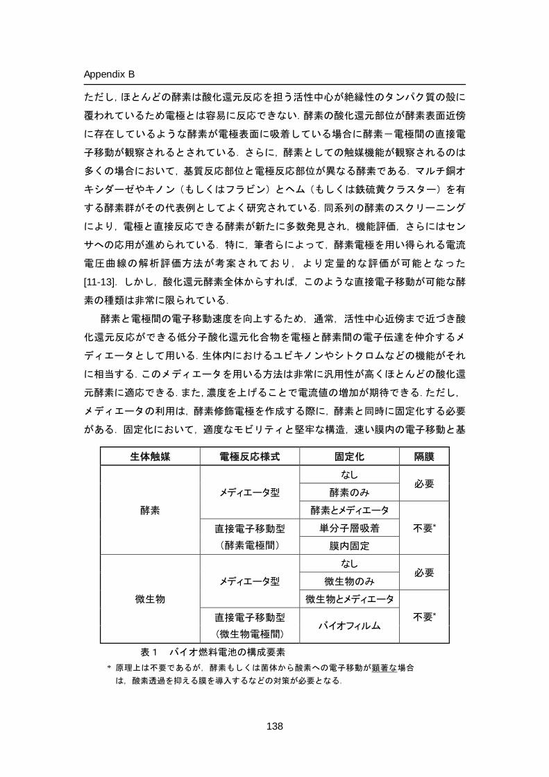
Appendix B
ただし,ほとんどの酵素は酸化還元反応を担う活性中心が絶縁性のタンパク質の殻に
覆われているため電極とは容易に反応できない.酵素の酸化還元部位が酵素表面近傍
に存在しているような酵素が電極表面に吸着している場合に酵素-電極間の直接電
子移動が観察されるとされている.さらに,酵素としての触媒機能が観察されるのは
多くの場合において,基質反応部位と電極反応部位が異なる酵素である.マルチ銅オ
キシダーゼやキノン(もしくはフラビン)とヘム(もしくは鉄硫黄クラスター)を有
する酵素群がその代表例としてよく研究されている.同系列の酵素のスクリーニング
により,電極と直接反応できる酵素が新たに多数発見され,機能評価,さらにはセン
サへの応用が進められている.特に,筆者らによって,酵素電極を用い得られる電流
電圧曲線の解析評価方法が考案されており,より定量的な評価が可能となった
[11-13].しかし,酸化還元酵素全体からすれば,このような直接電子移動が可能な酵
素の種類は非常に限られている.
酵素と電極間の電子移動速度を向上するため,通常,活性中心近傍まで近づき酸
化還元反応ができる低分子酸化還元化合物を電極と酵素間の電子伝達を仲介するメ
ディエータとして用いる.生体内におけるユビキノンやシトクロムなどの機能がそれ
に相当する.このメディエータを用いる方法は非常に汎用性が高くほとんどの酸化還
元酵素に適応できる.また,濃度を上げることで電流値の増加が期待できる.ただし,
メディエータの利用は,酵素修飾電極を作成する際に,酵素と同時に固定化する必要
がある.固定化において,適度なモビリティと堅牢な構造,速い膜内の電子移動と基
生体触媒 電極反応様式 固定化 隔膜
酵素
メディエータ型
なし 必要
酵素のみ
酵素とメディエータ
不要* 直接電子移動型
(酵素電極間)
単分子層吸着
膜内固定
微生物
メディエータ型
なし 必要
微生物のみ
微生物とメディエータ
不要* 直接電子移動型
(微生物電極間) バイオフィルム
表1 バイオ燃料電池の構成要素 * 原理上は不要であるが,酵素もしくは菌体から酸素への電子移動が顕著な場合
は,酸素透過を抑える膜を導入するなどの対策が必要となる.
138
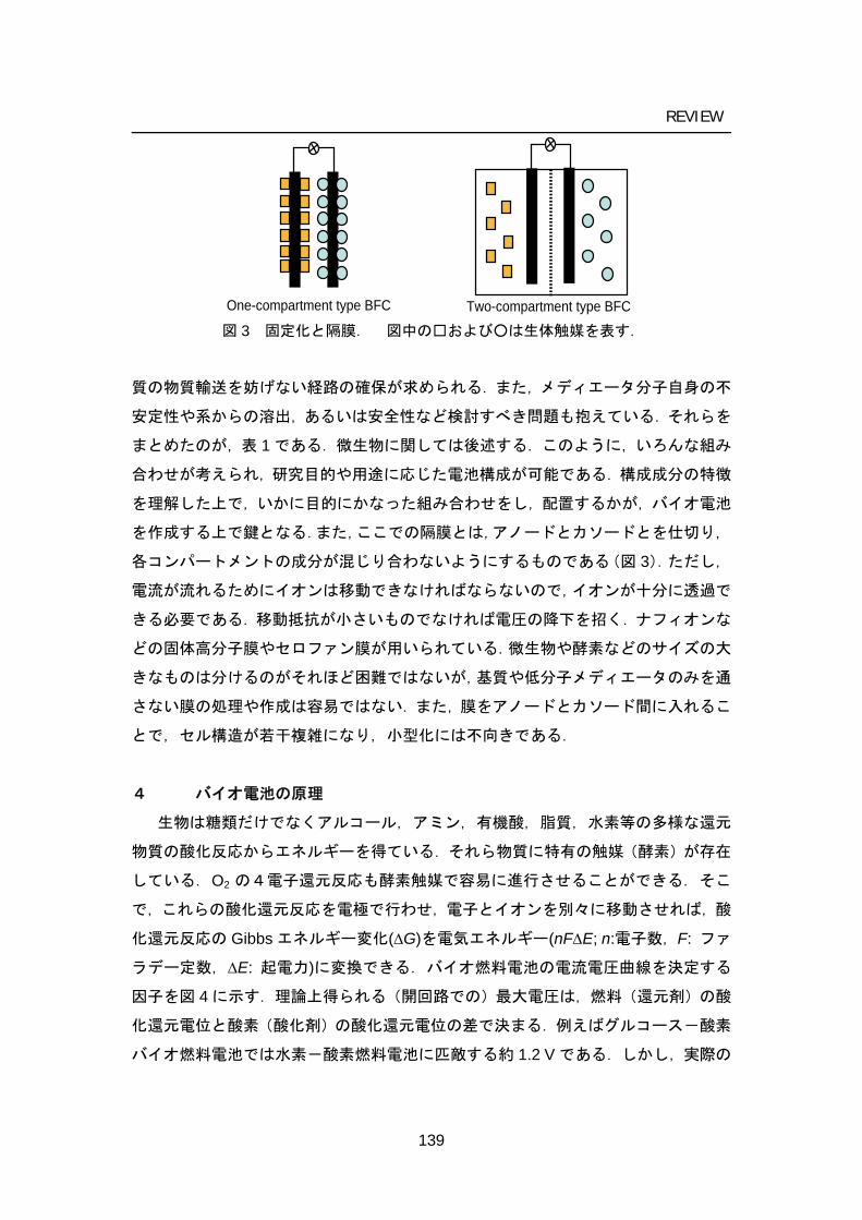
REVIEW
One-compartment type BFC Two-compartment type BFC 図 3 固定化と隔膜. 図中のおよびは生体触媒を表す.
質の物質輸送を妨げない経路の確保が求められる.また,メディエータ分子自身の不
安定性や系からの溶出,あるいは安全性など検討すべき問題も抱えている.それらを
まとめたのが,表 1 である.微生物に関しては後述する.このように,いろんな組み
合わせが考えられ,研究目的や用途に応じた電池構成が可能である.構成成分の特徴
を理解した上で,いかに目的にかなった組み合わせをし,配置するかが,バイオ電池
を作成する上で鍵となる.また,ここでの隔膜とは,アノードとカソードとを仕切り,
各コンパートメントの成分が混じり合わないようにするものである(図 3).ただし,
電流が流れるためにイオンは移動できなければならないので,イオンが十分に透過で
きる必要である.移動抵抗が小さいものでなければ電圧の降下を招く.ナフィオンな
どの固体高分子膜やセロファン膜が用いられている.微生物や酵素などのサイズの大
きなものは分けるのがそれほど困難ではないが,基質や低分子メディエータのみを通
さない膜の処理や作成は容易ではない.また,膜をアノードとカソード間に入れるこ
とで,セル構造が若干複雑になり,小型化には不向きである.
4 バイオ電池の原理
生物は糖類だけでなくアルコール,アミン,有機酸,脂質,水素等の多様な還元
物質の酸化反応からエネルギーを得ている.それら物質に特有の触媒(酵素)が存在
している.O2 の4電子還元反応も酵素触媒で容易に進行させることができる.そこ
で,これらの酸化還元反応を電極で行わせ,電子とイオンを別々に移動させれば,酸
化還元反応の Gibbs エネルギー変化(ΔG)を電気エネルギー(nFΔE; n:電子数,F: ファ
ラデー定数,ΔE: 起電力)に変換できる.バイオ燃料電池の電流電圧曲線を決定する
因子を図 4 に示す.理論上得られる(開回路での)最大電圧は,燃料(還元剤)の酸
化還元電位と酸素(酸化剤)の酸化還元電位の差で決まる.例えばグルコース-酸素
バイオ燃料電池では水素-酸素燃料電池に匹敵する約 1.2 V である.しかし,実際の
139
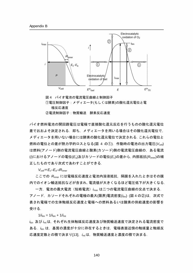
Appendix B
iRinner
Ec−Ea
Vcell
i
P
E
i
imax
Eo'fuel Eo'O2
Electrocatalytic oxidation of fuel
Electrocatalytic oxidation of O2
1 1
2
2ilimimax
図 4 バイオ電池の電流電圧曲線と制御因子 ①電圧制御因子:メディエータ(もしくは酵素)の酸化還元電位と電
極反応速度 ②電流制御因子:物質輸送 酵素反応速度
バイオ燃料電池の開回路電圧は電極で直接酸化還元反応を行うものの酸化還元電位
差でおおよそ決定される.即ち,メディエータを用いる場合はその酸化還元電位で,
メディエータを用いない場合には酵素の酸化還元電位で決定される.これらの電位と
燃料の電位との差が熱力学的ロスとなる(図 4 の①).作動時の電池の出力電圧(Vcell)
は燃料(アノード)側の電流電圧曲線と酸素(カソード)側の電流電圧曲線の,ある電流
(i)におけるアノードの電位(Ea)及びカソードの電位(Ec)の差から,内部抵抗(Rinner)の補
正したものであり次式であわすことができる.
Vcell=Ec–Ea–iRinner
ここでの Rinner には電極反応速度と電池内溶液抵抗,隔膜を入れたときはその膜
内でのイオン輸送抵抗などが含まれ,電流値が大きくなるほど電圧低下が大きくなる.
一方,電池の最大電流(短絡電流)imax は二つの電流電圧曲線の交点で決まる.
アノード,カソードそれぞれの電極の最大(限界)電流密度(ilim) (図 4 の②)は,次式で
表され電極での生体触媒反応速度と電極への燃料あるいは酸素の供給速度の影響を
受ける.
1/ilim = 1/ikin + 1/imt
ikin 及び imtは,それぞれ生体触媒反応速度及び物質輸送速度で決定される電流密度で
ある.ikin は,基質の濃度が十分に存在するときは,電極表面近傍の触媒量と触媒反
応速度定数との積で決まり[13],imtは,物質輸送速度と濃度の積で決まる.
140
REVIEW
また,負荷があるときの電力(P)は P = iVcellで与えられる.バイオエレクトロカタ
リシス反応の電流電圧曲線について詳しい理論的考察が行われおり,バイオ燃料電池
特性の定量的解析が可能である.バイオ燃料電池の電池出力特性をより定量的に評価
し議論するためにも,端子間抵抗を変化させたときに得られる電流-電圧曲線を提示
するべきである.また,形状因子 ff(fill factor)というパラメータで電流電圧曲線を
評価することもある.ff とは,起電力と最大電流の積に対する最大出力で与えられ,
出力を得るまでに溶液抵抗などで失ったエネルギー損失を反映する.1 に近いほどエ
ネルギロスが少ないことを表す.
ここで,バイオ電池に用いるメディエータの選択について,電池出力決定因子を
踏まえて概説する.メディエータとして利用の考えられる低分子酸化還元物質は,安
定性や溶解度,場合によっては酸素との反応性といった化学特性はもちろんのこと,
出力に及ぼす影響を考慮して選ぶ必要がある.すなわち,メディエータの酸化還元電
位が基質の酸化還元電位に近いほど,電池としてはより大きな電圧を得ることが出来
る.しかし,両者の酸化還元電位の差(反応の駆動力)が小さくなればなるほど,直
線自由エネルギー関係に従い,指数関数的に反応速度が遅くなり,電流値は小さくな
る[14,15].逆に大きな反応の駆動力があると,反応は拡散等など別の因子が律速段階
となる.メディエータの特性によっても,酵素との反応性は異なる.電池を組むとき
には,できるだけ電位差が小さくて,しかも反応速度が大きい酵素-メディエータ反
応系の探索が必要となる[16].そのためにもターゲット酵素の触媒活性についての詳
細な検討が必要である.また,微生物触媒を用いる場合,これに加えて,細胞膜や細
胞壁の透過性といった問題も考慮に入れて選択しなければならない.また,メディエ
ータ自身の電極反応速度(厳密にいうと,酵素反応速度に対する電極反応速度の比)
も重要となってくる.すなわち,メディエータの電極反応速度が(酵素反応に対して)
十分に速いときには,その電流-電圧曲線は,ネルンスト式で表されるシグモイド型
となる.しかし,電極反応速度が(酵素反応速度に対して非常に)遅いと,電流値が
大きくなるに従い,顕著な電圧の降下が見受けられる.
5 バイオ電池の特徴
バイオ電池は,①常温,常圧,中性付近で作動する;②糖やアルコールなどの多種多
様なバイオマスを還元剤として,酸素を酸化剤として利用する;③アノードとカソード
のみからなる非常にシンプルな構成である;④再生可能な資源材料から構成されている;⑤
高い安全性を有する,といった特徴を有している.これらバイオ電池の特徴は,触媒であ
141
Appendix B
る酵素の特徴を強く反映したものとなっている.
前述のようにバイオ電池では,適切な酵素(微生物)を選択することで,原理上
は,水素,メタノールはもとより,安全性の高いエタノールや糖,体内の血糖,飲食
物や環境中の有機物さらには有機物廃液などのバイオマス資源を直接燃料として発
電することができる.水素やアルコール等を燃料とする場合には白金等の無機電極触
媒に関する研究が進められているが,このような多種多様な燃料に対して,常温,常圧,
中性付近で機能する触媒は,現在のところ,酵素に勝るものはない.しかも,原理上で
は,いくつかの酵素反応を組み合わせることによって,燃料の多段階酸化反応を経て
完全酸化することができることである.例えば,生体中と同じように,グルコースや
エタノールを CO2まで完全酸化させれば,それぞれの電子数は 24,12 となり,バイ
オ電池の容量密度が向上する.糖などの(CH2O)n化合物において nCO2までの完全酸
化経路を構築することができれば,約 3600 Ah kg–1もの高い重量容量密度が得られる
計算となる.同様に,エタノールの場合,約 7000 Ah kg–1でありメタノールのそれを
上回る.高い容量密度は,携帯機器等で必要とされる長時間駆動に直結する.
酵素反応の大きな特徴の一つとして基質(反応物)に対する選択性が高いことが
挙げられる.当然酵素機能電極においても高い基質選択性があり,白金触媒電極で問
題となる燃料のクロスオーバーによる電圧降下などを心配する必要はない.また,こ
のことは,生体触媒を修飾させたアノードとカソードだけの非常にシンプルな電池が
でき,サイズ,形状などの制約が少ない自由度の高い電池開発が可能となる.
6 バイオ電池の応用分野
バイオ電池は,前節に述べた特性を活かした身近な化合物を燃料とする安全なユビキ
タス電源として,情報,通信,環境,医療といった分野での活躍,特に,一般的な電
源とは異なる様々な利用領域,あるいは隙間を埋める応用領域があると期待されてい
る.図 5 にその想定される応用分野をまとめた.
現在,酵素バイオ電池に関してもっとも注目を集めているのは,ペースメーカなどの体内
埋め込み型医療機器用の体内発電型電源や,発電量が血糖値に依存する性質を利用した血糖
センサやそれと連動したインシュリンポンプといった医療機器への展開も期待されている.
そのほか,補聴器用電源やドラッグデリバリーシステム(DDS)への応用も期待されている.
血糖の 3 日間連続モニタリング用使い捨て型微小電源の研究開発が進められている
が,さらに耐久性や安全性を高め,抗原抗体反応といった生体適合性などの問題を解
決する必要がある.微小バイオ電池は,血管埋め込みタイプのみならず,ユビキタス
142
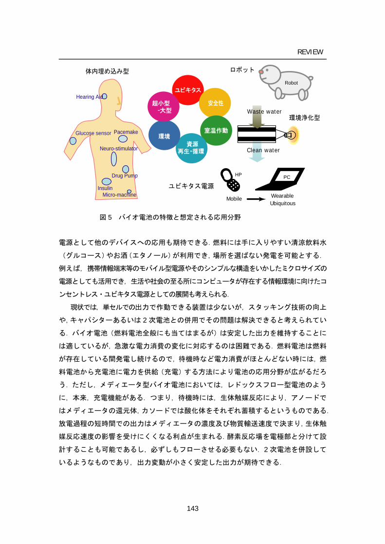
REVIEW
Pacemake
Insulin
Glucose sensor
Hearing Aid
Drug Pump
Neuro-stimulator
Micro-machine
PCHP
WearableMobileUbiquitous
Robot
Clean water
Waste water
ユビキタス電源
環境浄化型
ロボット体内埋め込み型
ユビキタス
安全性
室温作動
資源再生・循環
環境
超小型 -大型
図 5 バイオ電池の特徴と想定される応用分野
電源として他のデバイスへの応用も期待できる.燃料には手に入りやすい清涼飲料水
(グルコース)やお酒(エタノール)が利用でき,場所を選ばない発電を可能とする.
例えば,携帯情報端末等のモバイル型電源やそのシンプルな構造をいかしたミクロサイズの
電源としても活用でき,生活や社会の至る所にコンピュータが存在する情報環境に向けたコ
ンセントレス・ユビキタス電源としての展開も考えられる.
現状では,単セルでの出力で作動できる装置は少ないが,スタッキング技術の向上
や,キャパシターあるいは 2 次電池との併用でその問題は解決できると考えられてい
る.バイオ電池(燃料電池全般にも当てはまるが)は安定した出力を維持することに
は適しているが,急激な電力消費の変化に対応するのは困難である.燃料電池は燃料
が存在している間発電し続けるので,待機時など電力消費がほとんどない時には,燃
料電池から充電池に電力を供給(充電)する方法により電池の応用分野が広がるだろ
う.ただし,メディエータ型バイオ電池においては,レドックスフロー型電池のよう
に,本来,充電機能がある.つまり,待機時には,生体触媒反応により,アノードで
はメディエータの還元体,カソードでは酸化体をそれぞれ蓄積するというものである.
放電過程の短時間での出力はメディエータの濃度及び物質輸送速度で決まり,生体触
媒反応速度の影響を受けにくくなる利点が生まれる.酵素反応場を電極部と分けて設
計することも可能であるし,必ずしもフローさせる必要もない.2 次電池を併設して
いるようなものであり,出力変動が小さく安定した出力が期待できる.
143
Appendix B
7 バイオ電池の課題
以上のように,バイオ電池は,いろいろな夢を与えてくれるが,実用化を視野に
入れると,従来の電池の場合とは異なるいくつかの課題が山積している.酵素バイオ
電池をモバイル型電源としての利用を想定した場合,研究開発課題として,1)高電
流密度化,2)耐久性の向上,3)多電子酸化系の構築が挙げられる.さらには,バイ
オ電池の特性を活かした,4)電池構造や作動形態の検討も必要である.それらの課
題解決への取り組みと将来的な展望について,以下にいくつかの課題ごとに述べる.
1)高電流密度は,電極上での酵素反応速度,つまり反応場である電極上の酵素量と
酵素活性の積で決まる.つまり,高電流密度を目指すためには,高活性酵素の探
索,高密度かつ活性を保ったまま電極上に酵素を集積する技術の向上が求められ
る.また,当然のことながら基質の輸送などの問題を解決しなければならなくな
る.
2)安定性については,固定化酵素の工業レベルでの実用化の実例があるように,固
定化により酵素の立体構造が保持され,活性を所要期間安定に保つ可能性も考え
られる.酵素固定化法の改良により,酵素の安定化を実現することは不可能では
ない.一方,酵素の価格は,大量生産系を構築することにより,大幅に下げることがで
きる.ここが白金触媒との大きな違いであり,実際,胃腸薬などの医薬品や洗剤,血糖セ
ンサなどに大量に使用されており,既に十分な実績を積んでいる.以上のことを考慮に入
れると,乾電池のように使い捨て型という利用形態が実用的バイオ電池の第一段階
として考えられる.また,電池の耐久性を決める要因については,酵素の失活以
外にも酵素固定化膜自身の安定性(メディエータや酵素の電極からの脱離)や,
副生成物による被毒なども考えられる.状況に応じた適切な電池の設計により,
ある程度は対処できる.
3)一般的に一種の酸化還元酵素では,2 電子酸化しかできない.従って,グルコー
スやエタノールなどを燃料として用いた場合,エネルギー密度でリチウムイオン
電池など従来の電池を超えるには,濃度や出力の問題があるとしても,多電子反
応系の構築は必須である.従って,よく知られたペントースリン酸回路やクエン
酸回路などのような,一連の反応に関わる酵素をすべて用意した反応系を構築す
る必要がある.酸化還元酵素のみならず,様々な転移酵素や炭素-炭素間の結合
を切断する酵素などで構成され,相当数の酵素が必要となる.
4)より高い出力を単位スケール内で得るためには,その空間なり平面を最大限利用
する工夫が必要となる.また,求められているものが電圧もしくは電流かによっ
144
REVIEW
て,電極の配置(直列もしくは並列)が変わってくる.特に直列に配置する際に
は,適切な仕切りをいれるなどの十分な注意が必要となってくる.バッチ式もし
くはフロー式での電池作動によっても,燃料供給を含めた電池システムは変わっ
てくる.
8 酵素型バイオ電池の展開
バイオ電池が近年(2000 年以降),再び注目を集めるようになったのは,中性で
酸素の 4 電子還元ができたということ,修飾方法の改良によりアノード,カソード共
に「意外に」出力(電流密度)が出ることがわかったからである.それまでの研究に
おいて,酸素還元カソード極には,電極触媒として白金や,酵素ではサイトクローム
オキシダーゼ複合体やラッカーゼなどが使われていた[1-4, 17].中には,過酸化水素
を電子受容体とする電池も報告されていた.しかし,どれも中性条件下(多くのアノ
ード極酵素の作動条件)で用いるには問題があり,カソード極が電池作成の障壁とな
っていた.しかし,筆者らによって,ビリルビンオキシダーゼという活性中心に 4
つの銅を持つ酵素が,中性でも,熱力学および速度論的にも非常に優れた電極触媒活
性を示すことがわかった [18].この成果を受けてバイオ電池の研究が一気に広がっ
た.次に,後者の一番の要因として,電極表面に酵素と電子伝達メディエータを高密
度に固定化する研究が盛んに行われたからである.しかも,固定化することにより,
メディエータの外部からの供給や隔膜を不要とし,従来の固体高分子型燃料電池にな
い機能や特性を有した新しい電池ができる.しかし,酵素固定化電極に関する研究は
古くからあったが,バイオセンサへの応用を意識したものがほとんどで,高電流密度
を目指した研究はほとんどなかった.酵素活性を損なわず,かつ固定化酵素と電極間
の早い電子移動,酵素への迅速な基質の供給をいかに実現するかが最大の課題にあっ
た. A.Heller(米)らによって開発されたメディエータがペンダント状にぶら下がっ
たポリマーに酵素も共有結合させて固定化した電極を用いることで,大きな電流密度
を得ることに成功している[19, 20].筆者らも,カチオン性のポリマーにアニオン性
の酵素とメディエータの静電的相互作用による共固定化に成功しており,これらの酵
素修飾電極で得られる電流は,電流密度にしてmA cm–2のオーダーにまで達した[21].
電極の比表面積(幾何表面積に対する実効表面積)を向上させることで,さらに数倍
から数十倍の電流密度の向上を達成している.
さらなる高性能化を目指したとき,酵素性能の向上がバイオ電池すべての鍵を握
っていると言っても過言ではない.すなわち,固定化方法の改良などにより酵素の持
145
Appendix B
つ能力を最大限引き出しても限界はある.これからはバイオ電池に適した酵素の探索
が盛んに行われて,今後酵素活性,安定性ともに優れた新しい酵素が見つかってくる
可能性は高いものと信じている.そのためにも新規酵素のスクリーニング,評価方法
の基盤形成も重要な検討課題である.
実際,いくつかの新しい電池用酵素の開発が進められている. Armstrong らは酵
素を用いた隔膜のない画期的な水素-酸素燃料電池を作成し報告している[22].ちな
みに固体高分子形燃料電池では,水素やメタノール酸化と酸素還元の両方に白金が触
媒として用いられており,燃料が混じらないような工夫がされている.筆者らは以前,
酵素反応の基質選択性に注目し,酵素を電極触媒に利用する水素-酸素燃料電池を提
案した[23].しかし,隔膜のない燃料電池への展開は実現が困難であった.それは水
素の酸化反応を担うヒドロゲナーゼ(EC:1.12.99.6)のほとんどは,酸素や一酸化炭
素によって失活してしまうからである.しかし,彼らによる酸素耐性が高い Ralstonia
eutropha 由来の膜結合型ヒドロゲナーゼの発見が無隔膜型水素酸素バイオ電池へと
つながった.起電力は 1 V 弱と高く生体触媒の利点を活かせているが,電流値は非常
に小さい.今後の電極素材などの工夫で伸びる可能性はある.
全く新しい酵素も興味深いが,これまで知られていた酵素も使用条件や修飾方法
を見直すことで,潜在的にもっている機能を発揮させることもある.電極反応が可能
かどうかは酵素の構造,つまり酸化還元部位の存在位置に大きく依存しているが,電
極上への酵素固定化量や酵素-電極間の電子移動速度の向上については,酵素と電極
の相互作用を考慮に入れた適切なマッチングが不可欠である.電極側の構造(ナノス
ケールでの凹凸など)や表面特性の制御(電荷,親水疎水性,水素結合性)は酵素自
身のそれにくらべると容易であり,これまでに様々な角度から進められてきた.金電
極上への様々な官能基を有するアルカンチオールの修飾,プロモータと呼ばれる化合
物の添加,炭素電極上に電解化学的,化学的処理などがある.酵素との接触面積の増
加や電子授受部位との接近を目的として,電極および固定化担体として導電性ナノ材
料(金属,半導体もしくは炭素微粒子,メソ孔材料,カーボンナノチューブ,金属ナ
ノワイヤなど)の積極的な利用が一つの最近の傾向としてある[24].直接電子移動反
応が可能な酵素については,酵素構造とともに,使用する電極の特性も大きく影響を
受ける.
筆者のグループではごく最近に両極に酵素修飾電極を用いた糖-酸素バイオ電
池を発表している(図 6)[25].ビーカー内には果糖と酸素が溶けており,酵素修飾
電極を挿入しているだけという非常にシンプルな構成である.燃料酸化極にはフルク
146
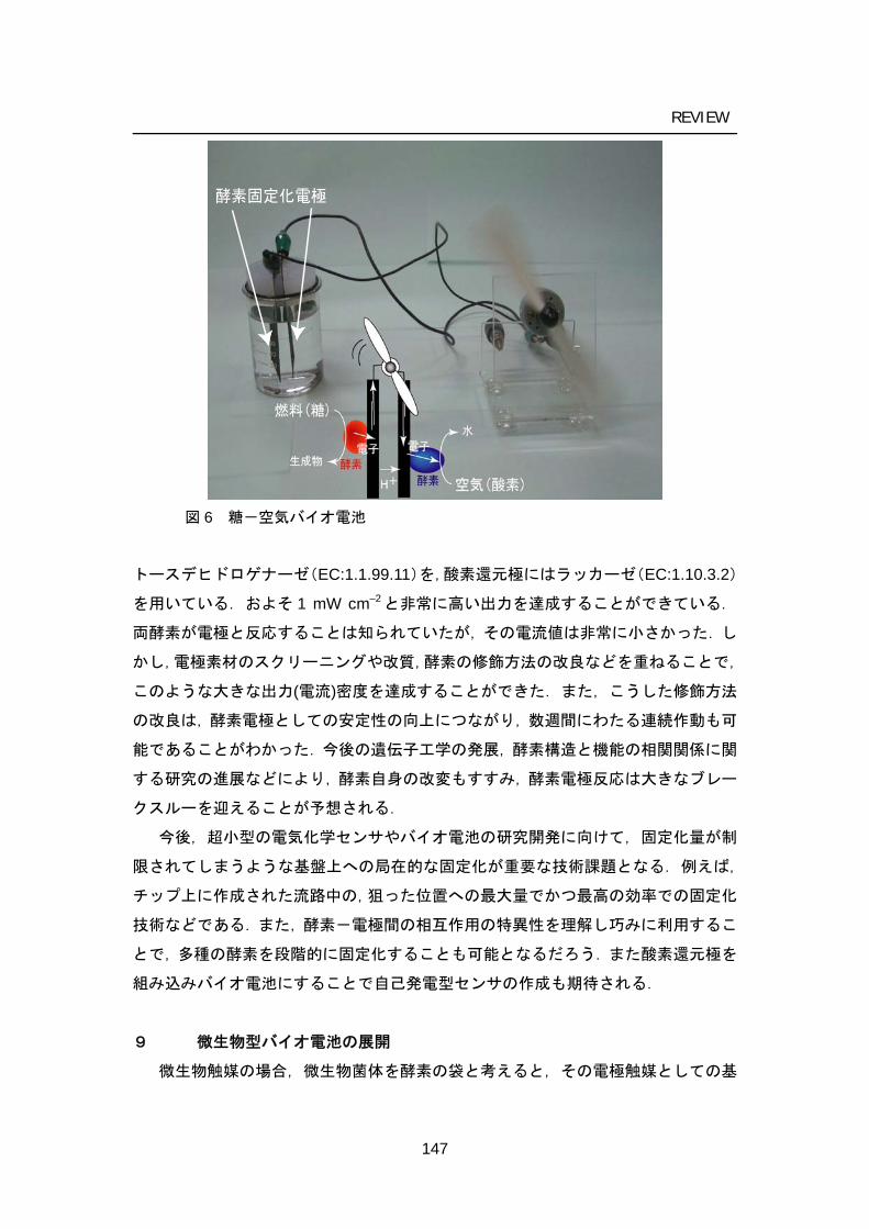
REVIEW
酵素固定化電極
図 6 糖-空気バイオ電池
トースデヒドロゲナーゼ(EC:1.1.99.11)を,酸素還元極にはラッカーゼ(EC:1.10.3.2)
を用いている.およそ 1 mW cm–2と非常に高い出力を達成することができている.
両酵素が電極と反応することは知られていたが,その電流値は非常に小さかった.し
かし,電極素材のスクリーニングや改質,酵素の修飾方法の改良などを重ねることで,
このような大きな出力(電流)密度を達成することができた.また,こうした修飾方法
の改良は,酵素電極としての安定性の向上につながり,数週間にわたる連続作動も可
能であることがわかった.今後の遺伝子工学の発展,酵素構造と機能の相関関係に関
する研究の進展などにより,酵素自身の改変もすすみ,酵素電極反応は大きなブレー
クスルーを迎えることが予想される.
今後,超小型の電気化学センサやバイオ電池の研究開発に向けて,固定化量が制
限されてしまうような基盤上への局在的な固定化が重要な技術課題となる.例えば,
チップ上に作成された流路中の,狙った位置への最大量でかつ最高の効率での固定化
技術などである.また,酵素-電極間の相互作用の特異性を理解し巧みに利用するこ
とで,多種の酵素を段階的に固定化することも可能となるだろう.また酸素還元極を
組み込みバイオ電池にすることで自己発電型センサの作成も期待される.
9 微生物型バイオ電池の展開
微生物触媒の場合,微生物菌体を酵素の袋と考えると,その電極触媒としての基
147
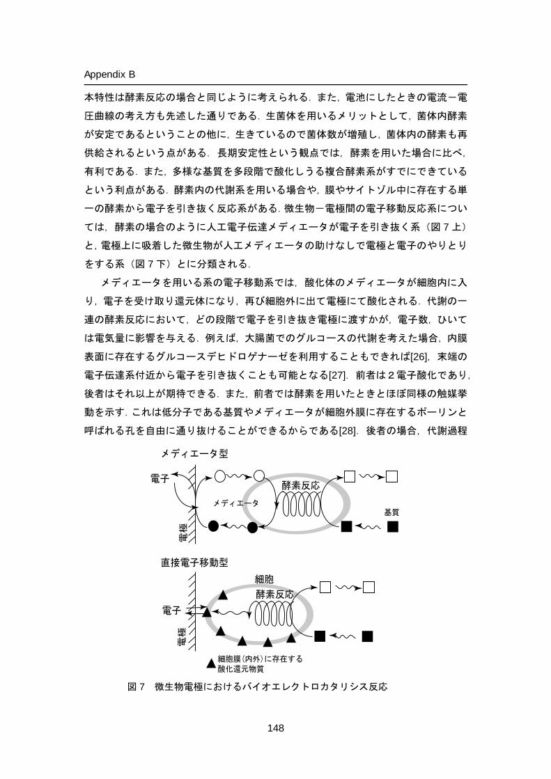
Appendix B
本特性は酵素反応の場合と同じように考えられる.また,電池にしたときの電流-電
圧曲線の考え方も先述した通りである.生菌体を用いるメリットとして,菌体内酵素
が安定であるということの他に,生きているので菌体数が増殖し,菌体内の酵素も再
供給されるという点がある.長期安定性という観点では,酵素を用いた場合に比べ,
有利である.また,多様な基質を多段階で酸化しうる複合酵素系がすでにできている
という利点がある.酵素内の代謝系を用いる場合や,膜やサイトゾル中に存在する単
一の酵素から電子を引き抜く反応系がある.微生物-電極間の電子移動反応系につい
ては,酵素の場合のように人工電子伝達メディエータが電子を引き抜く系(図 7 上)
と,電極上に吸着した微生物が人工メディエータの助けなしで電極と電子のやりとり
をする系(図 7 下)とに分類される.
メディエータを用いる系の電子移動系では,酸化体のメディエータが細胞内に入
り,電子を受け取り還元体になり,再び細胞外に出て電極にて酸化される.代謝の一
連の酵素反応において,どの段階で電子を引き抜き電極に渡すかが,電子数,ひいて
は電気量に影響を与える.例えば,大腸菌でのグルコースの代謝を考えた場合,内膜
表面に存在するグルコースデヒドロゲナーゼを利用することもできれば[26],末端の
電子伝達系付近から電子を引き抜くことも可能となる[27].前者は2電子酸化であり,
後者はそれ以上が期待できる.また,前者では酵素を用いたときとほぼ同様の触媒挙
動を示す.これは低分子である基質やメディエータが細胞外膜に存在するポーリンと
呼ばれる孔を自由に通り抜けることができるからである[28].後者の場合,代謝過程
電極
酵素反応
電子
直接電子移動型
電子
電極
メディエータ型
メディエータ基質
細胞膜(内外)に存在する酸化還元物質
酵素反応
細胞
図 7 微生物電極におけるバイオエレクトロカタリシス反応
148
REVIEW
およびその速度,細胞内のメディエータや基質の拡散がその出力に大きく影響を与え
る.引き抜くサイトや電子数は,菌体の種類や用いるメディエータの特性(酸化還元
電位,親水・疎水性,酸化還元特性など)に大きく影響される.逆に言うと,用いる
メディエータによって代謝経路を制御できるということにもなる[29].時には,菌体
の生育を損ねる場合もある.微生物の代謝反応過程で生じる還元体のうち,酸化還元
電位の低いものから選択的に電子を引き抜くことが困難であること,電極表面の触媒
活性密度が低くなることが,短所としてあげられる.
本来の電子の流れの途中から電子を引き抜くので,電池を構成する上でいろいろ
工夫が必要となってくる.例えば好気性菌では,酸素のある条件下においては,本来
の電子受容体である酸素に電子が流れ,メディエータ反応との競合が起こる.その結
果,電流値は大幅に減少するので,嫌気条件に保つ必要がある.もしくは,微生物の
代謝経路の遺伝子発現調整といった方針が有効かもしれない.また,このことは,酵
素反応でも観測され,本来酸素を電子受容体とするオキシダーゼを用いた場合でも,
同じような現象が観測される.
光合成細菌や藍藻を用いることで光エネルギーを電気エネルギーに変換する電
池を作成することができる.この電池では,主に光合成系 I と II の間からメディエー
タを介して電子を引き抜くことが実験的に示唆されている.また,アノードでの水の
酸化と,カソードでの酸素 4 電子還元反応とを組み合わせることで,燃料が光だけと
いうバイオ太陽電池を作成することができる[30, 31].
微生物の固定化方法については,酵素固定化方法のように,ポリマーでかためて
しまう方法もあるが,電極表面に微生物細胞集合体であるバイオフィルムを形成させ
るという方法も簡便で有効と考えられる.そのフィルム内に電子伝達メディエータを
固定させることが出来ればなおよいが,現在ではまだ成功例はない.燃料と同時に大
量の電子伝達メディエータを外部から供給しなければならないことになる.微生物燃
料電池は概念的には環境浄化と並行させて稼動できるが,人工的な低分子メディエー
タを利用するには限界がある.微生物自身(もしくは共生菌)が産み出した酸化還元
物質を電子伝達メディエータとして利用するという検討もなされている.
一方で,米国の Lovley らは,メディエータを利用することなく電極と直接電子の
やりとりを行う微生物細菌を触媒として,グルコースの 24 電子酸化が実現できると
発表して,その電池への応用とスクリーニング実験を盛んに行い注目を集めている
[32].細胞外膜に電子伝達を行うことのできる部位(膜内に存在するサイトクロムと
言われている)が露出しているようである.その後の研究により,微生物が産生する
149
Appendix B
ピルスと呼ばれる極細の繊維が,ナノワイヤとして電気伝導に関与するというモデル
が提唱されている[33,34]が,このモデルに関する議論はまだ続くものと思われる.
電子移動メカニズムに不明な点は残されているが,応用に向けた研究は盛んに行われ
ている.電極を海底等に浸積させることで,微生物が電極上にバイオフィルムを形成
し,適当なカソード極と組み合わせることで,メディエータを必要としない,海底の
汚泥中の有機物を燃料とするバイオ電池ができると報告されている[32].その出力は
酵素修飾電極に比べ極端に小さく,電力供給タイプとしての利用は考えにくい.海底
に大面積の電極を敷けば十分な電力を得ることが出来るとの主張もあるが,環境保全
型微生物バイオ電池としての展開が期待される.韓国の Kim らもほぼ同じ電子移動
系を有する微生物電池を研究しており[35],その BOD(生化学的酸素要求量)センサ
への応用を検討している.これは水中の有機物の濃度を発電出力としてモニタリング
するというものである[36].他方で,バイオ電池を搭載したロボットを作ろうという
プロジェクトが進行している[37].やはりバイオ電池の出力は非常に小さいので,電
池で発生した電力を2次電池に充電しながら利用するようである.
電池構成の改良により,最近では,メディエータを利用することなく,微生物バ
イオ電池で 0.7 mW cm–2程度の出力が発表されている[38].この後もリアクター設計
の技術と,微生物スクリーニングと,電極微生物間の電子移動反応メカニズムの解明
により,いよいよ現実的なものになってくることが期待される.
10 結言
環境保全,資源循環,脱石油の実現に向けて,省エネルギー・環境調和型社会シ
ステム構築は,地球レベルでの人間社会の将来を左右する極めて重要な今日的問題で
ある.その中で,化石資源以外のエネルギー源として,カーボンニュートラルという
特性を持つバイオマスへの関心が最近益々高まってきている.バイオ電池は多種多様
なバイオマス燃料を直接利用できる全く新しい電池として,潜在的な需要を掘り起こ
す革新的な電源として注目を集めるだけでなく,バイオ電池の進展は,エネルギー問
題だけでなく,環境問題解決へのひとつのアプローチとなると確信する.バイオマス
資源からメタンやメタノール,エタノール,あるいは水素などの燃料に変換して発電
する技術に比べ,物質変換,輸送,貯蔵,精製などの過程で生ずるロスを少なくする
ことができる.また原理上カルノーサイクルの制約を受けないので高いエネルギー変
換効率が期待される.つまり,バイオ燃料電池は,エネルギー資源の出発原料からみ
て全体の変換過程がシンプルで,その実質的なエネルギー変換効率は高く,まさに夢
150
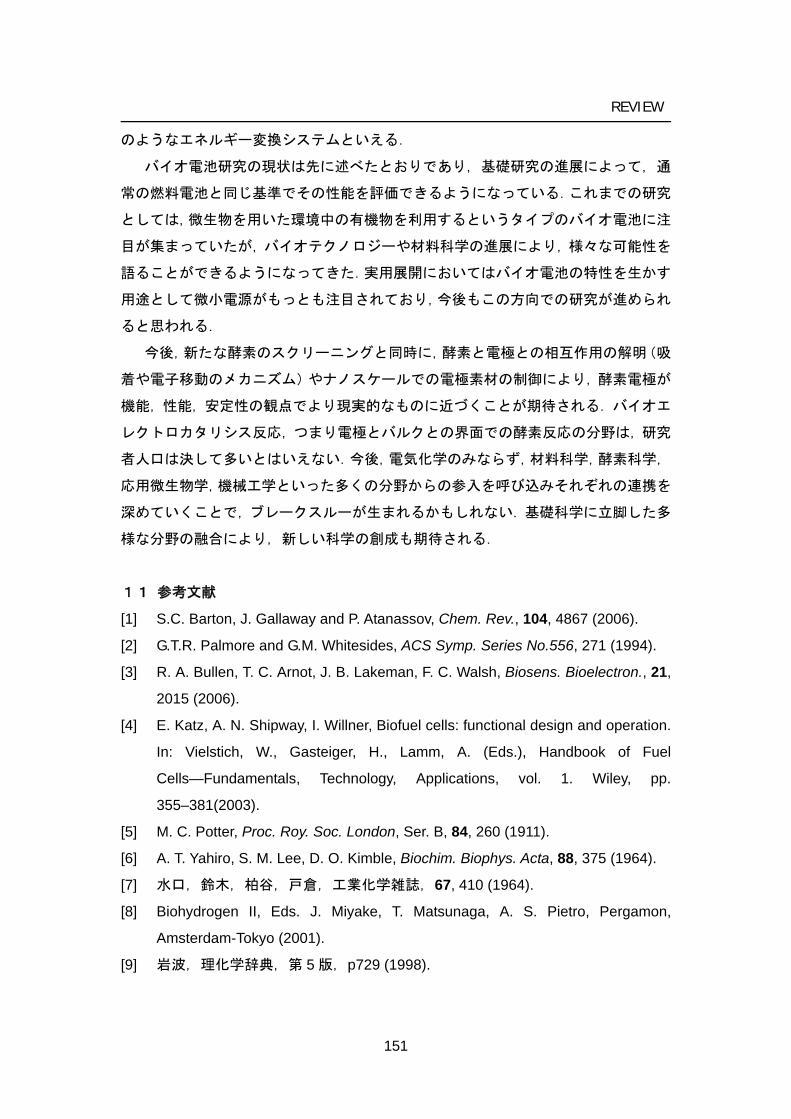
REVIEW
のようなエネルギー変換システムといえる.
バイオ電池研究の現状は先に述べたとおりであり,基礎研究の進展によって,通
常の燃料電池と同じ基準でその性能を評価できるようになっている.これまでの研究
としては,微生物を用いた環境中の有機物を利用するというタイプのバイオ電池に注
目が集まっていたが,バイオテクノロジーや材料科学の進展により,様々な可能性を
語ることができるようになってきた.実用展開においてはバイオ電池の特性を生かす
用途として微小電源がもっとも注目されており,今後もこの方向での研究が進められ
ると思われる.
今後,新たな酵素のスクリーニングと同時に,酵素と電極との相互作用の解明(吸
着や電子移動のメカニズム)やナノスケールでの電極素材の制御により,酵素電極が
機能,性能,安定性の観点でより現実的なものに近づくことが期待される.バイオエ
レクトロカタリシス反応,つまり電極とバルクとの界面での酵素反応の分野は,研究
者人口は決して多いとはいえない.今後,電気化学のみならず,材料科学,酵素科学,
応用微生物学,機械工学といった多くの分野からの参入を呼び込みそれぞれの連携を
深めていくことで,ブレークスルーが生まれるかもしれない.基礎科学に立脚した多
様な分野の融合により,新しい科学の創成も期待される.
11 参考文献
[1] S.C. Barton, J. Gallaway and P. Atanassov, Chem. Rev., 104, 4867 (2006).
[2] G.T.R. Palmore and G.M. Whitesides, ACS Symp. Series No.556, 271 (1994).
[3] R. A. Bullen, T. C. Arnot, J. B. Lakeman, F. C. Walsh, Biosens. Bioelectron., 21,
2015 (2006).
[4] E. Katz, A. N. Shipway, I. Willner, Biofuel cells: functional design and operation.
In: Vielstich, W., Gasteiger, H., Lamm, A. (Eds.), Handbook of Fuel
Cells—Fundamentals, Technology, Applications, vol. 1. Wiley, pp.
355–381(2003).
[5] M. C. Potter, Proc. Roy. Soc. London, Ser. B, 84, 260 (1911).
[6] A. T. Yahiro, S. M. Lee, D. O. Kimble, Biochim. Biophys. Acta, 88, 375 (1964).
[7] 水口,鈴木,柏谷,戸倉,工業化学雑誌,67, 410 (1964).
[8] Biohydrogen II, Eds. J. Miyake, T. Matsunaga, A. S. Pietro, Pergamon,
Amsterdam-Tokyo (2001).
[9] 岩波,理化学辞典,第 5 版,p729 (1998).
151
Appendix B
[10] K. Kano, T. Ikeda, Electrochemistry, 71, 86 (2003). [11] S. Tsujimura, T. Nakagawa, K. Kano, T. Ikeda, Electrochemistry, 72, 437
(2004); (Chapter 2-1).
r 2-2).[12] S. Tsujimura, K. Kano, T. Ikeda, J. Electroanal. Chem., 576, 113
(2005); (Chapte
[13] S. Tsujimura, Review of Polarography, 52, 81, (2006) (in Japanese); (Appendix
A).
[14] S. M. Zakeeruddin, D. M. Fraser, M-K. Nazeeruddin and M. Grätzel, J.
Electroanal. Chem., 337, 253 (1992).
[15] K. Takagi, K. Kano and T. Ikeda, J. Electroanal. Chem., 445, 211 (1998). [16] S. Tsujimura, K. Kano, and T. Ikeda, Chem. Lett., 1022 (2002); (Chapter 3).
[17] G. T. R. Palmore, H. Bertschy, S. H. Bergens and G. M. Whiteside, J.
Electrocanal. Chem., 443, 155 (1998).
[18] S. Tsujimura, H. Tatsumi, J. Ogawa, S. Shimizu, K. Kano and T. Ikeda, J.
Electroanal. Chem., 496, 69 (2001); (Chapter 1 -1).
[19] T. Chen, S. C. Barton, G. Binyamin, Z. Gao, Y. Zhang, H-.H. Kim, A. Heller, J.
Am. Chem. Soc., 123, 8630 (2001). [20] S. Tsujimura, K. Kano, T. Ikeda, Electrochemistry, 70, 940 (2002); (Chapter 4-3).
[21] T. Nakagawa, S. Tsujimura, K. Kano, and T. Ikeda, Chem. Lett., 32, 54
(2003); (Chapter 1 -2)., S. Tsujimura, M. Kawaharada, T. Nakagawa, K. Kano,
and T. Ikeda, Electrochem. Commun., 5, 138 (2003); (Chapter 1 -3).
[22] K.A. Vincent, J.A. Cracknell, O. Lenz, I. Zebger, B. Friedrich, and F.A.
Armstrong, Proc. Natl. Acad. Sci. USA, 102, 16951 (2005).
[23] S. Tsujimura, M. Fujita, H. Tatsumi, K. Kano, T. Ikeda, Phys. Chem. Chem.
Phys., 3, 1331 (2001); (Chapter 4 -1).
[24] L. Murphy, Curr. Opin. Chem. Biol., 10, 177 (2006).
[25] Y. Kamitaka, S. Tsujimura, N. Setoyama, T. Kajino, K. Kano, Phys. Chem.
Chem. Phys., submitted.
[26] D. Iswantini, K. Kano, and T. Ikeda, Biochem. J., 350, 917 (2000).
[27] H. P. Bennetto, J. L. Stirling, K. Tanaka, C. A. Vega, Biotechnol. Bioeng., 25, 559
(1983).
[28] H. Tatsumi, K. Kano, and T. Ikeda, J. Phys. Chem. B, 104, 12079 (2000).
[29] S. Yamazaki, T. Kaneko, N. Taketomo, K. Kano, and T. Ikeda, Appl. Microbiol.
152
REVIEW
153
Biotechnol., 59, 72 (2002).
[30] M. Torimura, A. Miki, A. Wadano, K. Kano, and T. Ikeda, J. Electroanal. Chem.,
496, 21 (2001).
[31] S. Tsujimura, A. Wadano, K. Kano, and T. Ikeda, Enz. Microbial Tech., 29, 225
(2001); (Chapter 4 -2).
[32] S. K. Chaudhuri, D. R. Lovley, Nature Biotech., 21, 1229 (2003).
[33] G. Reguera, K.D. McCarthy, T. Mehta, J.S. Nicoll, M.T. Tuominen, D.R. Lovley,
Nature, 435, 1098 (2005).
[34] Y.A. Gorby, S. Yanina, J.S. McLean, K.M. Rosso, D. Moyles, A. Dohnalkova, T.J.
Beveridge, I.S. Chang, B.H. Kim, K.S. Kim, D.E. Culley, S.B. Reed, M.F. Romine,
D.A. Saffarini, E.A. Hill, L. Shi, D.A. Elias, D.W. Kennedy, G. Pinchuk, K.
Watanabe, S. Ishii, B. Logan, K.H. Nealson, J.K. Fredrickson, Proc. Natl. Acad.
Sci., U.S.A., 103, 11358 (2006).
[35] H. J. Kim, H. S. Park, M. S. Hyun, I. S. Chang, M. Kim, B. H. Kim, Enz. Microbial
Tech., 30, 145 (2002).
[36] I. S. Chang, J. K. Jang, G. C. Gil, M. Kim, H. J. Kim, B. W. Cho, B. H. Kim,
Biosens. Bioelectro., 19, 607 (2004).
[37] S. Wilkinson, Autonomous Robots, 9, 99 (2000).
[38 ] B.E. Logan, J.M. Regan, Envirom. Sci. Technol., 40, 5172 (2006).

Acknowledgments
I wish to express my sincere thanks to Prof. Tokuji Ikeda and Prof. Kenji Kano. Their scientific insight, patience and personal concern have been invaluable contributions to this research.
Thanks are due as well to all the members of laboratory of Bio-Analytical and Physical Chemistry for their helpful discussion and collaborations. Seiya Tsujimura 2006
154
List of publications Bioelectrocatalytic reduction of dioxygen to water at neutral pH using bilirubin
oxidase as an enzyme and 2,2'-azinobis (3-ethylbenzothiazolin-6-sulfonate) as an electron transfer mediator
Tsujimura, S., Tatsumi, H.,Ogawa, J., Shimizu, S., Kano, K., and Ikeda, T. J. Electroanal. Chem., 496(1/2), 69-75 (2001). (Chapter 1, 1) Bioelectrocatalysis-based dihydrogen/dioxygen fuel cell operating at
physiological pH Tsujimura, S., Fujita, M., Tatsumi, H., Kano, K., and Ikeda, T. Phys. Chem. Chem. Phys., 3(3), 1331-1335 (2001). (Chapter 4, 1) Photosynthetic bioelectrochemical cell utilizing cyanobacteria and
water-generating oxidase Tsujimura, S., Wadano, A., Kano, K., and Ikeda, T. Enz. Microbial Tech., 29 (4-5), 225-231 (2001) (Chapter 4, 2) Glucose/O2 biofuel cell operating at physiological conditions Tsujimura, S., Kano, K., and Ikeda, T. Electrochemistry, 70 (12), 940-942 (2002). (Chapter 4, 3) Electrochemical oxidation of NADH catalyzed by diaphorase conjugated with
poly-1-vinylimidazle complexed with Os(2,2'-dipyridylamine)2Cl Tsujimura, S., Kano, K., and Ikeda, T. Chem. Lett., 2002 (10), 1022-1023. (Chapter 3)
155
List of Publications
Bilirubin oxidase and [Fe(CN)6]3–/4– modified electrode allowing
diffusion-controlled reduction of O2 to water at pH 7.0 Nakagawa, T., Tsujimura, S., Kano, K., and Ikeda, T. Chem. Lett., 32 (1), 54-55 (2003). (Chapter 1, 2) Mediated bioelectrocatalytic O2 reduction to water at highly positive electrode
potentials near neutral pH Tsujimura, S., Kawaharada, M., Nakagawa, T., Kano, K., and Ikeda. T. Electrochem. Commun., 5 (2), 138-141 (2003). (Chapter 1, 3) Kinetic study of direct bioelectrocatalysis of dioxygen reduction with bilirubin
oxidase at carbon electrodes Tsujimura, S., Nakagawa, T., Kano, K., and Ikeda, T. Electrochemistry, 72 (6) 437-439 (2004). (Chapter 2, 1) Bilirubin oxidase in multiple layer catalyzes four-electron reduction of
dioxygen to water without redox mediators Tsujimura, S., Kano, K., and Ikeda, T. J. Electroanal. Chem., 576(1), 113-120 (2005) (Chapter 2, 2) Mediated spectroelectrochemical titration of proteins for redox potential
measurements by a separator-less one-compartment bulk electrolysis method
Tsujimura, S., Kuriyama, A., Fujieda, N., Kano, K., and Ikeda, T. Anal. Biochem., 337 (2), 325-331 (2005) (Chapter 5)
156
List of Publications
Related papers not included in the thesis are listed below.
Separator-less one-compartment bulk electrolysis with a small auxiliary electrode and its application to spectroelectrochemistry,
Kuriyama, A., Arasaki, M., Fujieda, N., Tsujimura, S., Kano, K., and Ikeda, T., Electrochemistry, 72 (7), 484-486 (2004). Kinetic study of direct electron transfer between enzyme and carbon electrodes Tsujimura, S., Kano, K., and Ikeda, T. Chemical Sensors, 20 (Supplement B), 770-771 (2004). Novel FAD-dependent glucose dehydrogenase to construct dioxygen-insensitive glucose
biosensor, Tsujimura, S., Kojima, S., Kano, K., Ikeda, T., Sato, M., Sanada, H., and Omura, H., Biosci. Biotech. Biochem., 70(3), 654-659 (2006). Electron transfer kinetics between PQQ-dependent soluble glucose dehydrogenase and
mediators, Okumura, N., Abo, T., Tsujimura, S., and Kano, K., Electrochemistry, 74(8), 639-641 (2006). Electrochemical quartz crystal microbalance study on adsorption of bilirubin oxidase as a
catalyst in bioelectrocatalytic reduction of dioxygen, Kamitaka, Y., Tsujimura, S., Ikeda, T., and Kano, K., Electrochemistry, 74(8), 642-644 (2006). Escherichia coli-catalyzed bioelectrochemical oxidation of acetate in the presence of
mediators, Wang, Y.F., Cheng, S.S., Tsujimura, S., Ikeda, T., and Kano, K., Bioelectrochemistry, 69, 74-81 (2006). Potential-step coulometry of D-glucose using novel FAD-dependent glucose
dehydrogenase, Tsujimura, S., Kojima, S., Ikeda, T., Kano, K., Anal. Bioanal. Chem., 386(3), 645-651(2006).
157
List of Publications
158
Osmium complex grafted on a carbon electrode surface as a mediator for a
bioelectrocatalytic reaction, Tsujimura S., Katayama, A., and Kano, K., Chem. Lett., 35 (11), 1244-1245 (2006). Bioelectrocatalytic reduction of O2 catalyzed by CueO from Escherichia coli adsorbed on a
highly oriented pyrolytic graphite electrode, Miura, Y., Tsujimura, S., Kamitaka, Y., Kurose, S., Kataoka, K., Sakurai, T., and Kano, K., Chem. Lett., 36(1), 132-133 (2007). Steady-state bioelectrocatalytic current, Tsujimura, S., Rev. Polarogra., 52, 81-89 (2006) (in Japanese). Effects of axial ligand mutation of the type I copper site in bilirubin oxidase on direct electron
transfer-type bioelectrocatalytic reduction of dioxygen, Kamitaka, Y., Tsujimura, S., Kataoka, K., Sakurai, T., Ikeda, T., and Kano, K., J. Electroanal. Chem., in press. High current density bio-electrolysis of D-fructose at fructose dehydrogenase-adsorbed and
ketjen black-modified electrodes without a mediator, Kamitaka, Y., Tsujimura, S., and Kano, K., Chem. Lett., in press. Dependence of the steady-state catalytic currents on the thickness of an
enzyme-mediator-immobilized layer fabricated by layer–by-layer method Ishii, A., Tsujimura, S., and Kano, K., Bunseki Kagaku, submitted. Fructose/dioxygen biofuel cell based on direct electron transfer-type bioelectrocatalysis, Kamitaka, Y., Tsujimura, S., Setoyama, N., Kajino, T., and Kano, K., Phys. Chem. Chem. Phys., submitted.