Embed Size (px)
Citation preview
1
The 31st International Electric Propulsion Conference, University of Michigan, USA
Distribution A: Approved for public release; distribution unlimited
Total and Differential Sputter Yields of Boron Nitride
Measured by Quartz Crystal Microbalance
IEPC-2009-042
Presented at the 31st International Electric Propulsion Conference,
University of Michigan • Ann Arbor, Michigan • USA
September 20 – 24, 2009
B Rubin1, J. L. Topper
2 and A. P. Yalin
3
Colorado State University, Fort Collins, Colorado 80523, USA
We present differential sputter yield measurements of boron nitride due to
bombardment by xenon ions. A four-grid ion optics system is used to achieve a collimated
ion beam at low energy (<100 eV). A quartz crystal microbalance (QCM) is used to measure
differential sputter yield profiles of condensable components from which total sputter yields
can also be determined. We report total and differential sputter yields of three grades of
boron nitride due to bombardment by xenon ions for ion energies in the range of 60-500 eV
and ion incidence angles of 0°, 15°, 30°, and 45° from normal. We also present preliminary
results of the temperature dependence of the sputter yield. Comparisons with published
values are made where possible.
Nomenclature
As = QCM sensor area
E = ion energy
E* = characteristic energy describing the differential sputter yield profile shape
Eth = threshold sputtering energy
JB,avg = time-averaged current of ions and energetic neutrals incident on the target
k = fitting coefficient
MB = boron atomic mass
MN = nitrogen atomic mass
R = mass accumulation rate
rqcm = distance from the target center to the QCM
YBN = full BN sputter yield
Y,YQCM = deposited condensable sputter yield
y, yMZ = volumetric differential sputter yield
α = ejection polar angle of sputtered atoms measured relative to the surface normal
β = incidence angle of bombarding ions measured relative to the surface normal
φ = ejection azimuthal angle of the sputtered atoms measured in the plane of the target surface
ρ = density of the target material
I. Introduction
ON sputtering is a primary life-limiting mechanism in electric propulsion (EP) thrusters used for satellite and
space exploration1-12
. Owing to the relatively long lifetimes (5-10+ years) of EP thruster devices and the
complexity and expense of experimental tests, effects of sputter erosion and deposition are often studied with
1 Postdoctoral researcher, Department of Mechanical Engineering, [email protected]
2 Graduate student, Department of Mechanical Engineering, [email protected]
3 Associate professor, Department of Mechanical Engineering, [email protected]
I

2
The 31st International Electric Propulsion Conference, University of Michigan, USA
Distribution A: Approved for public release; distribution unlimited
numeric codes. For erosion (lifetime) studies, the aim is to compute the amount of surface erosion due to the
bombarding ions. Such modeling requires knowledge of the total sputter yields (Y) of the eroding materials at the
ion conditions (energy and incidence angle) of interest. Deposition modeling additionally requires differential
(angular) sputter yields (y(α,φ)) in order to track the trajectories of sputtered particles. Total and differential sputter
yield profiles have been measured with a multitude of techniques, a partial list of which includes weight loss10,12
,
collector plates13-14
, mass spectrometry15
, quartz crystal microbalance3-7,9-11,16-17
, Rutherford backscattering18-19
,
radioactive tracers 20
, and cavity ring-down spectroscopy 21-22
.
We are specifically interested in the sputtering of boron nitride (BN) because of its widespread use as an
insulator material in the acceleration channel of stationary plasma thrusters (SPTs). Erosion of the insulator channel
is the dominant thruster life-limiting mechanism in SPTs. Sputter erosion removes material from the channel wall
and eventually exposes the underlying magnetic yoke, causing the magnetic field profile to be altered and the end of
life to be reached. Furthermore, deposition of the sputtered BN can contaminate spacecraft surfaces (e.g. solar
panels or thermal control surfaces). Despite the importance of BN erosion there is a lack of basic sputtering data on
BN. Numerical modeling of thruster erosion23-25
shows that the ions most critical to the erosion process have
relatively low energy (≤100 eV). Measurements in this energy range are challenging since the low sputter yields can
lead to signals below the detection sensitivity of the measurement system; additionally, it can be difficult to obtain
collimated monoenergetic ion beams at these energies. The goal of the present study is to contribute towards filling
this gap. In this work we detail development of an experimental configuration for low energy BN sputter
measurements. We report differential and total sputter yields for several grades of BN at ion energies down to 60
eV, obtained with a QCM deposition sensor3-7,9-11,16-17
. In section II we discuss the experimental apparatus and
procedures used for data analysis. Results of validation measurements performed by using molybdenum as a control
are presented in section III. Section IV contains a summary of the experimental results, including total and
differential sputter yields of HBC, HBR, and HP grades of boron nitride under bombardment by xenon ions.
Comparisons with available published values are provided. Finally, conclusions are given in section V.
II. Experimental Apparatus and Procedure
A. Overview of Sputter Measurement System
Total and differential sputter yields are measured using a quartz crystal microbalance (QCM) deposition monitor.
The experimental apparatus is shown in Fig. 1. The main elements of the system have been previously described5-7, 9-
11,26. In this subsection we give an overview of its essential features, while the following subsections detail specific
aspects and recent modifications. An improvement relative to our past work7 is that both weight loss and QCM
measurements are performed concurrently in the same facility. The role of weight loss measurements is discussed
below. The ion source and QCM are housed within a 0.125 m3 stainless steel vacuum chamber (43 cm ID x 76 cm
long main section), equipped with a 1500 liter/s cryogenic pump (CTI-8). The chamber base pressure is 5×10⁻⁵
Pa
giving a working pressure of approximately 2 to 5×10⁻³
Pa (corrected for Xe). Based on the chamber pressure and
Figure 1. Left: Schematic diagram of experimental set-up. Right: Solid-model showing angle definitions.

3
The 31st International Electric Propulsion Conference, University of Michigan, USA
Distribution A: Approved for public release; distribution unlimited
temperature, the mean free path for boron atoms (i.e. sputtered particles) is 1.7 m such that ~10% of the boron atoms
will experience a collision with background xenon atoms before reaching QCM surface (17.4 cm away). Some
particles will therefore be deflected prior to reaching the QCM (lowering the measured yield), but other particles not
originally directed at the QCM will be deflected to deposit on it. The effect of these collisions is hard to estimate
exactly but is at most 10% which, as compared to the 30% uncertainty on reported yields, is considered to be
negligible. The DC ion source with two-grid and four-grid ion optics, specially designed for low energy operation, is
described below in more detail. A rotatable target-mount is positioned 23 cm downstream of the ion source. As
shown in Fig. 1, the QCM is rotated in an arc above the target and the target itself is rotated azimuthally.
Combinations of these movements allow us to probe over the hemisphere above the target, thereby obtaining
differential sputter yield profiles. Both the QCM and target rotation are performed using 25000 step stepper motors,
which are controlled using a motion control system (Parker CompuMotor). A personal computer with LabView is
used for data logging. Detailed discussion of the QCM sensor is provided in subsection IIF.
B. Definition of Angles
The angles used to describe the direction of ion incidence and the ejections angles of sputtered particles are
shown in Fig. 1. We define as follows: β is the incidence angle of bombarding ions measured relative to the surface
normal (β=0 for normal incidence), α is the ejection polar angle of sputtered atoms measured relative to the surface
normal, and φ is the ejection azimuthal angle of the sputtered atoms measured in the plane of the target surface
(defined so that φ =0 is in the forward sputter direction i.e. in the forward direction of the plane containing the
surface normal and the incident ion directions).
C. Ion Source
A DC Kaufman ion source using a dual thoriated tungsten filament as a discharge cathode and thoriated tungsten
filament as a neutralizer is used11
. The four-grid ion optics system, designed using an in-house ffx code26, 27
and
fabricated in-house, produces collimated beams at the low ion energies of interest to this work (20-350 eV). For
higher energy measurements (250 – 500 eV), a two-grid ion optics system is used. Both grid sets can be used for the
250-350 eV range and the results obtained using two grid sets are similar. For both grid sets, typical beam
parameters include a xenon flow rate of 0.05 mg/s, a beam current of 1-4 mA, a discharge voltage of 20 to 40 V, and
a (beam) neutralizer current of 150% of the beam current. During measurements, the ion current leaving the source
is recorded. Determination of the sputter yield requires knowledge of the current of energetic particles (ions and fast
neutrals) incident on the sputtering target. As in our past work9-11
, we make corrections for charge-exchange and
scattering. The charge-exchange beam generates fast neutrals which, depending on scattering angles, may bombard
the target. The resulting correction is to multiply the measured source current by 0.8-0.95, depending on the
chamber pressure and ion energy.
Ion source characterization was performed to determine the bombardment conditions26
. The beam divergence
angle, defined as the angle from normal including 90% of the beam current, was found as 12° from a beam profile
measured with a collimated Faraday probe (the divergence angle increases slightly with beam energy),
corresponding to a beam diameter of approximately 13.5 cm at the sample plane. A four-grid retarding potential
analyzer (RPA) was used to measure the ion energy distribution, yielding a full width at half maximum (FWHM) of
6-19 V, increasing with beam energy. To determine the charge states of the ions an ExB probe was used. No triply
charged ions were detected. The average double-to-single number density ratio was ≤5% for beam energies between
80 eV and 250 eV, dropping with decreasing energy. For beam energies below 80 eV the number density of doubles
fell below the detection limit (1%). The doubly-charged ions have twice the energy of singles but are counted as two
charges in the current measurements. Because the measured yields are relatively linear and the fraction of doubles is
low, simple estimates show their effect to be negligible.
D. Boron Nitride Targets, Surface Charging, and Moisture Effects
Test results reported herein are for HBC, HBR, and HP grades of Boron Nitride (BN). Each of these materials is
formed by hot-pressing and corresponds to the graphite-like allotrope of BN. In the base plane, atoms are held
together by strongly directed hexagonal arrays of covalent bonds, resulting in unique electrical, thermal, and
mechanical properties. The HBC and HBR materials were obtained from General Electric's Advanced Ceramics
(currently Momentive Performance Materials). Calcium borate is used as binder in HBR, while no binder is used in
HBC. The two grades have generally similar properties though with some differences. For example, HBR has higher
thermal expansion, higher moisture absorption, and higher volume resistivity at elevated temperatures. The HP
grade is obtained from Saint-Gobain and uses calcium borate as binder. Figure 2 shows Scanning Electron
4
The 31st International Electric Propulsion Conference, University of Michigan, USA
Distribution A: Approved for public release; distribution unlimited
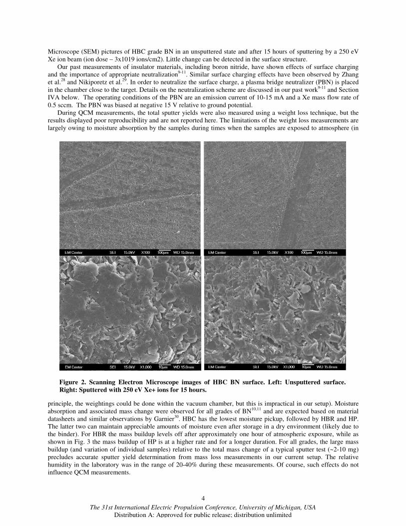
Microscope (SEM) pictures of HBC grade BN in an unsputtered state and after 15 hours of sputtering by a 250 eV
Xe ion beam (ion dose – 3x10¹⁹ ions/cm2). Little change can be detected in the surface structure.
Our past measurements of insulator materials, including boron nitride, have shown effects of surface charging
and the importance of appropriate neutralization9-11
. Similar surface charging effects have been observed by Zhang
et al.28
and Nikiporetz et al.29
. In order to neutralize the surface charge, a plasma bridge neutralizer (PBN) is placed
in the chamber close to the target. Details on the neutralization scheme are discussed in our past work9-11
and Section
IVA below. The operating conditions of the PBN are an emission current of 10-15 mA and a Xe mass flow rate of
0.5 sccm. The PBN was biased at negative 15 V relative to ground potential.
During QCM measurements, the total sputter yields were also measured using a weight loss technique, but the
results displayed poor reproducibility and are not reported here. The limitations of the weight loss measurements are
largely owing to moisture absorption by the samples during times when the samples are exposed to atmosphere (in
principle, the weightings could be done within the vacuum chamber, but this is impractical in our setup). Moisture
absorption and associated mass change were observed for all grades of BN10,11
and are expected based on material
datasheets and similar observations by Garnier30
. HBC has the lowest moisture pickup, followed by HBR and HP.
The latter two can maintain appreciable amounts of moisture even after storage in a dry environment (likely due to
the binder). For HBR the mass buildup levels off after approximately one hour of atmospheric exposure, while as
shown in Fig. 3 the mass buildup of HP is at a higher rate and for a longer duration. For all grades, the large mass
buildup (and variation of individual samples) relative to the total mass change of a typical sputter test (~2-10 mg)
precludes accurate sputter yield determination from mass loss measurements in our current setup. The relative
humidity in the laboratory was in the range of 20-40% during these measurements. Of course, such effects do not
influence QCM measurements.
Figure 2. Scanning Electron Microscope images of HBC BN surface. Left: Unsputtered surface.
Right: Sputtered with 250 eV Xe+ ions for 15 hours.

5
The 31st International Electric Propulsion Conference, University of Michigan, USA
Distribution A: Approved for public release; distribution unlimited
Another phenomenon that can influence weight loss
measurements is xenon ion implantation into the sample.
If a significant number of xenon ions are implanted in the
sample, the measured mass loss and apparent sputter yield
would be reduced. To check the influence of ion
implantation, X-ray photoelectron spectrometry (XPS)
analysis was performed on a HBC BN sample using a
PHI 5800 XPS system. A previously unused sample was
sputtered for 15 hours with a 250 eV ion beam (ion dose –
3x10¹⁹ ions/cm2) after which XPS analysis was
performed. The analysis shows implanted xenon with an
atomic fraction of 0.1%. Angularly resolved XPS
measurements show that the implanted xenon is only in a
thin near-surface layer. The measured atomic fraction
versus electron emission angle is shown in Fig. 4. The
increase of atomic fraction with angle shows that the
depth of xenon implantation does not exceed a few
nanometers. From the point of view of weight loss, simple
numeric estimates show that the mass of implanted xenon
is negligible compared to the mass change due to
sputtering.
E. Boron Nitride Sputter Products
In deposition mode, the QCM allows determination of
differential sputter yields through measurement of mass
accumulation (of sputtered particles) on its surface. For condensable components, sticking coefficients are assumed
to be unity. Note that sticking coefficients for “new layers” and very thin layers (typically 10’s of Angstroms) may
be less than unity, but once a sufficient layer thickness of a given material has accumulated, sticking coefficients for
condensables are generally unity 31
. As will be further discussed, the sputtered particles from BN may consist of a
mix of condensable and non-condensable
components. To study the chemical composition of the layer
deposited on the QCM surface during the BN sputter
yield measurements, the surface of the QCM as well
as a HBC BN target were analyzed using XPS. For
the QCM surface layer, B 1s and N 1s spectral lines
were detected in a proportion of 5.5:1 B:N. It is
important to realize that these features are due to all of
the corresponding material regardless of atomic or
molecular composition, e.g. the B 1s is due to boron
from boron atoms, BN, oxides etc. Therefore, the
5.5:1 ratio immediately indicates that sputtering is
predominantly as atoms of B and N (or possibly Bx
and Ny) but not so much as BN or other BxNy, since
there is much more B on the QCM relative to N). We
make this conclusion under the assumption the B
atoms (or Bx) condense onto the QCM while N or N2
does not. We use the NIST XPS database32
for line
assignments and other features of the spectra are as
follows. There is variation in reported B 1s line locations, but the consensus is that pure atomic B is at 186-188 eV,
B from BN is at ~190-191 eV, and B from B2O3 is at ~192-194 eV. Atomic B is not detected in the target or QCM
surface likely because it oxidizes (to B2O3) in the atmosphere (and the materials were exposed to atmosphere prior
to the XPS measurements). Clearly the BN feature is large from the BN target (which shows both BN and B2O3) but
small from the QCM surface (consistent with our hypothesis). In summary, the salient point is that the majority of
the
0 500 1000 15000
0.05
0.1
0.15
Time (min)
Mass G
ain
(g)
Figure 3. Mass change as a function of time of
atmospheric exposure for six different HP BN
samples. Zero time corresponds to 90 minutes
after removal from vacuum chamber, and mass
gain is relative to sample mass at 90 minutes. The
starting total sample mass is approximately 150 g.
0 20 40 60 80 1000.1
0.2
0.3
0.4
0.5
Angle (degrees)
Xe a
tom
ic f
raction (
%)
Figure 4 . Angularly resolved XPS measurements
of Xe in BN target.

6
The 31st International Electric Propulsion Conference, University of Michigan, USA
Distribution A: Approved for public release; distribution unlimited
B detected in the QCM surface is in the form of B2O3 as would be expected if sputtering of B is predominantly is
predominantly as B atoms, or Bx, (but not as BN) which deposit on the QCM and subsequently oxidize.
Sputtering predominantly as atoms is also consistent with past mass spectrometry results1,28,33
and multi-
component sputtering theory. The XPS analysis of a sputtered BN sample performed by Garnier30
demonstrated
little variation between the boron and nitrogen fractions in the sample before and after sputtering, which suggests
that boron and nitrogen are sputtered at approximately equal rates as would be expected based on the bulk
composition. Therefore, assuming sputtering as atoms with only B depositing on the QCM, the full BN yield is
related to the deposited condensable yield as
B NBN QCM
B
M MY Y
M
+= ⋅
(1)
where MB is the mass of boron, MN is the mass of nitrogen, YQCM is the QCM-measured yield, and YBN is the full
BN yield (this equation applies for both differential and total yields). Owing to the reactivity of atomic nitrogen, it is
also possible that N atoms form N2 as they leave the surface, but in the case of sputter products being B and N2 (with
B depositing on the QCM), equation (1) still holds.
F. QCM Sensor and Measurement Procedure
We use a deposition controller (Sigma Instruments SQC-339) that reads the crystal frequency to 0.001 Hz and an
RC-cut quartz crystal as opposed to the more conventional AC-cut crystal. The RC-cut crystal (Tangidyne
Corporation) is very accurate for deposition of thin films. Increased sensitivity is achieved by adjusting the stress
coefficients of the quartz plate using advanced fabrication methods
The quartz crystal resonance frequency is extremely sensitive to temperature variation so the QCM should be
maintained at constant temperature during measurements. A programmable digital temperature controller with
refrigerating/heating circulator (PolyScience 9002) is used to control the temperature of the QCM. The water
circulates through the stainless steel body of the QCM housing with the temperature of the water bath controlled to
±0.01oC. As the crystal is moved to different positions its incident heat flux varies; therefore, although the
temperature of the water stays constant, the actual crystal temperature is different at different locations (α angles). A
K-type thermocouple wire embedded in a copper holder silver-soldered to the back of the QCM crystal holder
monitors QCM temperature, and each sputter yield measurement is started only after the temperature of the crystal
has stabilized.
For a given incidence angle β (obtained by tilting the target), the differential sputter yield profile is obtained by
measuring the sputter yield over two chords above the target: φ=0o/180
o and φ �= 60
o/240
o (where the latter, by
symmetry, also corresponds to φ=120o/300
o for azimuthally symmetric sputtering profiles). A total of 34-36
Figure 5. XPS results for the HBC BN target (a) and QCM surface (b). For the HBC BN target, fitted peaks
(and their sum) are shown.

7
The 31st International Electric Propulsion Conference, University of Michigan, USA
Distribution A: Approved for public release; distribution unlimited
positions above the target are typically sampled. At a given measurement point the volumetric differential sputter
yield, y(α,φ), in units of mm3/C/sr, is determined using
2
,
( , )( , )
qcm
B avg s
R ry
J A
α φα φ
ρ
= (2)
where R(α, φ) is the measured mass accumulation rate (found from the QCM’s deposition monitor device), ρ is the
density of the target material (close to 2 mg/cm3 for all grades of BN used), JB,avg (C/s) is the time-averaged current
of bombarding particles (ions and energetic neutrals) incident on the target, rqcm is the distance from the target center
to the QCM (17.4 cm), and As is the QCM sensor area (0.535 cm2). The quantity As/rqcm
2 corresponds to the solid
angle that the QCM sensor subtends while R(α, φ)/ρJB,avg corresponds to the volume of sputtered material per
bombarding charge. It is important to emphasize that the directly measured quantity is the mass buildup of
condensable particles on the QCM and the volumetric differential sputter yield should be considered in this way. (In
fact the “volume” may not really correspond to any physically observed volume since it corresponds to the
equivalent volume due to the mass of the deposited material if one uses the density of the full target material; of
course conversion to the deposited mass yield simply requires removing the density from (2)). Finally, as discussed
in subsection IIE, equation (1) can be used to convert the measured QCM yield (from (2)) to the corresponding full
BN yield.
G. QCM Signal Analysis.
Analysis and fitting of differential sputter yield profiles requires appropriate functional forms. At our conditions,
stopping is predominantly due to elastic (nuclear) collisions and is generally in the linear cascade regime (emitted
particles are secondary or higher generation recoils) or single knock-on regime (emitted particles are primary
recoils)1. A classical theory for the linear cascade regime was originally developed by Sigmund
35. Independent of
ion incidence angle, the original Sigmund theory predicts sputtering profiles that are azimuthally symmetric and
approximately diffuse in shape, corresponding to cosine-like profiles of the form y~cos(α)n (n=1 for a diffuse
profile). More recent experimental and numerical studies show a range of profile shapes. For normally incident
ions on polycrystalline and amorphous targets, cosine-like profiles are generally observed with increasingly under-
cosine shapes as ion energy is lowered and increasingly over-cosine shapes for higher ion energies5-7,9-10,15,35-37
. For
obliquely incident ions at relatively high ion energy, observed profiles also tend to be azimuthally symmetric.
However, for lower ion energies the measured profiles tend to be asymmetric with increased sputtering in the
forward direction5-7,9-10,16,20,35
. Similar profiles have been modeled on a theoretical basis37-39
.
As a means to describe the measured differential sputter yield profiles we use expressions from Zhang40
, based
on work from Yamamura38-39
, to which we introduce two fit parameters. We term the resulting expressions as
Modified Zhang (MZ)7:
( )
( )( ) ( ) ( ) ( ) ( )
*
*
cos 1 31 cos sin sin cos
4 21 cos
MZ
Y Ey
EE
E
αβ γ α π β α φ
πβ
= ⋅ − +
−
(3a)
( )( )
( )
( ) ( )( )( )
( )( )
2 22
2 3
cos 3sin 13sin 1 1 sinln
1 sinsin 2sin
α αα αγ α
αα α
+ − += +
− (3b)
where yMZ is the differential sputter yield, Y is the total sputter yield, E is the ion energy, E* is a characteristic
energy describing the profile shape, and the angles are as defined above (the expression is properly normalized so
that integrating the differential sputter yield, yMZ, over the sputtering hemisphere gives Y). The formulation
decouples the amplitude and shape of the profiles through the use of Y and E* respectively. More recent work by
Zhang et al.41
also discusses the use of a varying energy parameter. In general, rather than using the MZ expressions
for a priori calculation, we treat Y and E* as free fit-parameters which we determine from (least-squares fitting)

8
The 31st International Electric Propulsion Conference, University of Michigan, USA
Distribution A: Approved for public release; distribution unlimited
experimental data. Note that profile shapes are determined by the ratio E*/E and for high ion energy (E*/E << 1)
the MZ expression reduces to the diffuse yield (y=Ycos(α)/π).
H. Measurement Procedure
Targets are pre-sputtered to better represent the conditions found in long-duration EP operating applications. Pre-
sputtering of HBC and HBR samples is by a 500 eV ion beam with a current density of ~0.1 mA/cm² for 15 hours,
while the HP sample is pre-sputtered by a 750 eV ion beam with a current density of ~1 mA/cm² for 2 hours. An
order-of-magnitude estimate for the typical dose of incident ions on a target prior to testing is 1019 ions/cm2
(corresponding to a sputtered surface thickness of several microns). Target contamination effects are estimated to be
negligible, since for typical conditions the flux of ions incident on the target is approximately 10 times higher than
the flux of nitrogen (the major contaminant) to the target7. The samples are also heated under the chamber filaments
for at least 30 minutes prior to sputtering to remove moisture and to reach thermal steady-state. Test durations are
fixed such that the QCM has time (at each position) to sufficiently stabilize relative to thermal and background
noise. Test times vary from several hours for higher energy tests to as long as 20 hours for lower energy tests,
corresponding to the ion doses of 6.7x10¹⁸-4.5x10¹⁹ ions/cm2.
III. Measurement System Validation
Validation of our sputter yield measurements is performed by using molybdenum as a control. While there is
variation in data from different research groups,
molybdenum sputter yields are reasonably well
characterized3,6,7,42,43
. We have measured the total sputter
yield of Mo at normal incidence at energies of 150, 250 and
350 eV. As shown in Fig. 6, the total yields (found from the
Y parameter of the best-fit MZ profile) are self-consistent
and in reasonable agreement with the Yamamura and
Tawara curve fit42-43
. The currently reported yields (shown
as CSU 2008) are somewhat lower than those previously
measured using the same apparatus with two-grid ion optics
(shown as CSU 2007) though the difference is within
experimental uncertainty7. Although our values are
approximately a factor of two lower then Kolasinski’s
(measured by etching a thin Mo layer off the QCM
surface)3, they are in good agreement with the data of
Doerner44
(weight loss method). These results are taken as
validation of the measurement methods and in particular of
the assumption that the sticking coefficient of the QCM may
be taken as unity for condensables.
IV. Results & Discussion
A. Total Sputter Yields
Figure 7 shows total sputter yields of the three BN grades, determined from the Y parameter of the best-fit MZ
profile (equivalent to integrating the best-fit differential profile) as a function of ion energy for normal incidence.
The total yields of Fig. 7 (and Fig. 8) are only due to condensable particles depositing on the QCM, and equation (1)
can be used to find the corresponding full BN yields. The measurements of total sputter yield values are performed
multiple times for the majority of the data points. Measurements in the energy range of 60-350 eV are performed
using the four-grid ion optics, while the range of 250-500 eV uses the two-grid ion optics. For the cases when
several measurements were done at the same conditions, the average value is reported. Total sputter yields of HBC
and HBR grades are nearly identical, although HP yields at 200 and 250 eV are somewhat higher. However, the
differences between the yields of HP and the other two grades are likely not statistically significant as the
differences are within the experimental uncertainty. Experimental uncertainty on measured differential sputter yields
and total sputter yields are estimated to be about 30% based on the repeatability of the sputter yield measurements.
Where possible, we compare our total sputter yields with measurements and modeled values from other research
groups. Figure 9 shows our recent measurements for HBC BN along with weight loss measurements by Semenov46
,
Garnier30
, Abashkin47
, Kim48
, and modeled values from Yim23
. In this case we have scaled our yields using (1) to
0 100 200 3000
0.02
0.04
0.06
E(eV)
Y(m
m3/C
)
CSU 2008
CSU 2007
Doerner
Kolasinski
Yamamura
Figure 6. Total sputter yield versus ion energy for
normal incidence, Xe+ on Mo.

9
The 31st International Electric Propulsion Conference, University of Michigan, USA
Distribution A: Approved for public release; distribution unlimited
represent full BN sputtering yields (not just the measured
condensable particles). Not all of the authors specify the
grade of BN used. The values we are currently reporting
are high relative to past measurements. The difference in
the measured sputter yields may be attributed to the
difference in the properties of different BN grades (e.g.
presence of binders). Even for a given BN grade produced
by the same manufacturer, the material properties can
vary. Comparison against weight loss measurements may
be influenced by moisture effects as discussed in
connection with Fig.3. Also, if samples have been heated,
it is possible that surface changes have been induced. In
terms of Yim’s modeled values, certain details of the
molecular binding were selected to achieve agreement
with the published experimental data. Finally, inadequate
surface neutralization may lead to low apparent yields as
further discussed below. The validation measurements
presented above suggest that if a systematic error is
present in our data, it results in sputter yields that are
lower, not higher, than true values.
The values reported here are also higher then the
values we have previously reported using the weight loss
method in a different vacuum chamber10
likely owing to
inadequate surface charge neutralization or variations in
current density values in the previous work. While the
latter would not lead to substantial error (<~30%), the
former could be significant. A key differences in the
present setup compared to that used for the past total
yield measurements10
is that the present setup allows real-
time sputter measurements using the QCM. This
capability allows us to select the emitted current from the
PBN by monitoring its effect on the measured sputter
yield. Initially the sputter rate increases with the
neutralization current prior to reaching saturation when
the target is adequately neutralized. Measurements
reported here are safely in the saturated regime. In
contrast, in the past setup the neutralization current was
pre-selected based on the total beam current value and the
neutralizer characteristics, and may have been inadequate
for complete surface neutralization thereby leading to
lower measured sputter yields.
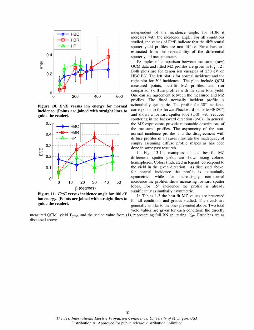
B. Differential Sputter Yields As described in subsection IIG, MZ expressions are
used to fit the profiles and the parameter E*/E describes
the shape of the profile. Figure 10 shows the variation in
E*/E for normal incidence as a function of ion energy for
the three grades of BN. In this energy range the parameter
E*/E tends to increase with energy for all grades of BN but
other apparent features (e.g. maxima) are likely not
statistically significant (i.e. fall within the noise of the
data). Figure 11 shows the variation in E*/E at 100 eV as a
function of incidence angle for the three grades of BN. For
HBC and HP grades the value of the parameter is almost
0 200 400 6000
0.02
0.04
0.06
0.08
E(eV)
YQ
CM
(m
m3/C
)
HBC
HBR
HP
Figure 7. Total condensable sputter yield from
QCM versus ion energy for normal incidence.
0 20 400.005
0.01
0.015
0.02
0.025
0.03
0.035
β (degrees)
YQ
CM
(m
m3/C
)
HBC
HBR
HP
Figure 8. Total condensable sputter yield from
QCM versus incidence angle for 100 eV ion
energy.
0 200 400 6000
0.05
0.1
0.15
0.2
YB
N (
mm
3/C
)
E(eV)
Semenov
Garnier
Abashkin
Kim
Yim (simulation)
Current w ork (HBC)
Figure 9. Total BN sputter yields as compared
with published values.
10
The 31st International Electric Propulsion Conference, University of Michigan, USA
Distribution A: Approved for public release; distribution unlimited
independent of the incidence angle, for HBR it
increases with the incidence angle. For all conditions
studied, the values of E*/E indicate that the differential
sputter yield profiles are non-diffuse. Error bars are
estimated from the repeatability of the differential
sputter yield measurements. Examples of comparison between measured (raw)
QCM data and fitted MZ profiles are given in Fig. 12 .
Both plots are for xenon ion energies of 250 eV on
HBC BN. The left plot is for normal incidence and the
right plot for 30° incidence. The plots include QCM
measured points, best-fit MZ profiles, and (for
comparison) diffuse profiles with the same total yield.
One can see agreement between the measured and MZ
profiles. The fitted normally incident profile is
azimuthally symmetric. The profile for 30° incidence
corresponds to the forward/backward plane (φ=0/180°)
and shows a forward sputter lobe (α<0) with reduced
sputtering in the backward direction (α>0). In general,
the MZ expressions provide reasonable descriptions of
the measured profiles. The asymmetry of the non-
normal incidence profiles and the disagreement with
diffuse profiles in all cases illustrate the inadequacy of
simply assuming diffuse profile shapes as has been
done in some past research.
In Fig. 13-14, examples of the best-fit MZ
differential sputter yields are shown using colored
hemispheres. Colors (indicated in legend) correspond to
the yield in the given direction. As discussed above,
for normal incidence the profile is azimuthally
symmetric, while for increasingly non-normal
incidence the profiles show increasing forward sputter
lobes. For 15° incidence the profile is already
significantly azimuthally asymmetric.
In Tables 1-3 the best-fit MZ values are presented
for all conditions and grades studied. The trends are
generally similar to the ones presented above. Two total
yield values are given for each condition: the directly
measured QCM yield YQCM, and the scaled value from (1), representing full BN sputtering, YBN. Error bas are as
discussed above.
0 200 400 6000
0.2
0.4
E*/
E
HBC
HBR
HP
Figure 10. E*/E versus ion energy for normal
incidence. (Points are joined with straight lines to
guide the reader).
0 10 20 30 40 500
0.1
0.2
0.3
0.4
0.5
E*/
E
β (degrees)
HBC
HBR
HP
Figure 11. E*/E versus incidence angle for 100 eV
ion energy. (Points are joined with straight lines to
guide the reader).

11
The 31st International Electric Propulsion Conference, University of Michigan, USA
Distribution A: Approved for public release; distribution unlimited
Table 1. Total Sputter Yields (Y) and Characteristic Energies (E*) of HBC BN.
Ion energy (eV) Incidence angle (o) YQCM (mm
3/C) YBN (mm
3/C) E* (eV)
60 0
0.0063
0.0145 8
100 0 0.0136
0.0312 18
100 15 0.0142
0.0327 13
100 30 0.0145
0.0333 18
100 45 0.0181
0.0417 21
150 0 0.0170
0.0390 13
200 0 0.0268
0.0614 40
250 0 0.0291
0.0669 63
250 15 0.0234 0.0539 65
-50 0 500
0.001
0.002
0.003
0.004
0.005
0.006
α (degrees)
y(m
m3/C
/sr)
Zhang
Diffuse
QCM
-50 0 500
0.005
0.01
0.015
α (degrees)
y(m
m3/C
/sr)
Zhang
Diffuse
QCM
(a) (b)
Figure 12. Example of QCM data with best-fit MZ profiles for 250 eV ions on HBC at normal incidence (a),
and at 30° (b).
(a) (b)
Figure 13. Differential sputter yield profiles for HBC grade BN. Normal incidence and different beam
energies (a). Varying incidence angles at a beam energy of 100 eV (b). Arrows show the direction of ion
incidence. Units are mm3/C/sr.

12
The 31st International Electric Propulsion Conference, University of Michigan, USA
Distribution A: Approved for public release; distribution unlimited
250 30 0.0287 0.0660 96
250 45 0.0258 0.0594 86
300 0 0.0367
0.0842 67
350 0 0.0316
0.0726
84
350 15 0.0200 0.0459 97
350 30 0.0243 0.0559 148
350 45 0.0308 0.0707 163
500 0 0.0423
0.0973 123
500 15 0.0473 0.109 150
500 30 0.0485 0.112 207
500 45 0.0545 0.125 231
Table 2. Total Sputter Yields (Y) and Characteristic Energies (E*) of HBR BN.
Ion energy (eV) Incidence angle (o) YCond (mm
3/C) YBN (mm
3/C) E* (eV)
60 0 0.0064 0.015 2
100 0 0.0158 0.036 6
100 15 0.0185 0.0425 27
100 30 0.0218 0.0502 38
100 45 0.0233 0.0535 27
200 0 0.025 0.058 53
250 0 0.034 0.079 46
250 15 0.0276 0.0634 58
250 30 0.0566 0.130 69
250 45 0.0497 0.114 97
350 0 0.0365 0.0838 94
350 15 0.0328 0.0753 134
350 30 0.0514 0.118 135
350 45 0.0644 0.148 182
500 0 0.0388 0.089 191
500 15 0.0669 0.154 213
500 30 0.0657 0.151 250
500 45 0.101 0.233 261
Table 3. Total Sputter Yields (Y) and Characteristic Energies (E*) of HP BN.
Ion energy (eV) Incidence angle (o) YCond (mm
3/C) YBN (mm
3/C) E* (eV)
60 0 0.004 0.010 5
100 0 0.015 0.034 25
100 15 0.015 0.034 19
100 30 0.018 0.041 10
100 45 0.016 0.037 15
200 0 0.035 0.080 61
250 0 0.053 0.122 71
13
The 31st International Electric Propulsion Conference, University of Michigan, USA
Distribution A: Approved for public release; distribution unlimited
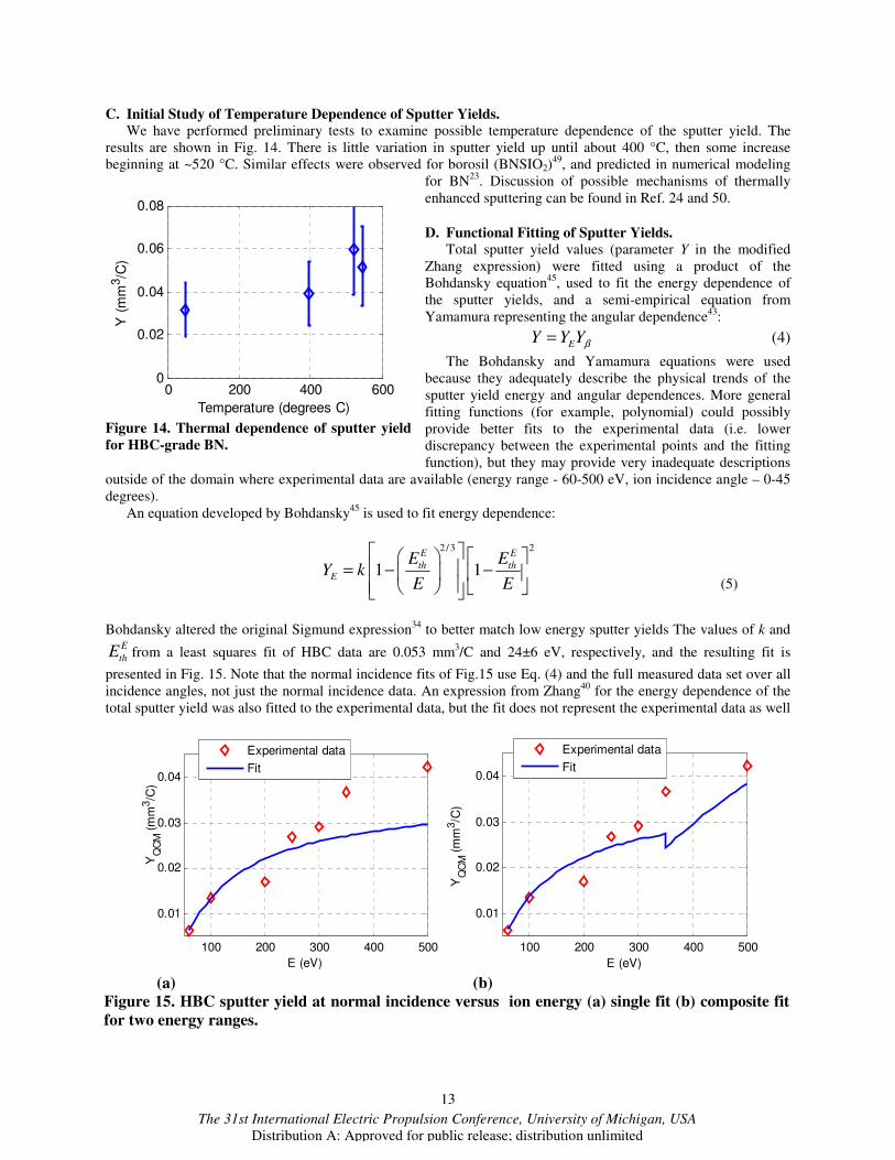
C. Initial Study of Temperature Dependence of Sputter Yields.
We have performed preliminary tests to examine possible temperature dependence of the sputter yield. The
results are shown in Fig. 14. There is little variation in sputter yield up until about 400 °C, then some increase
beginning at ~520 °C. Similar effects were observed for borosil (BNSIO2)49
, and predicted in numerical modeling
for BN23
. Discussion of possible mechanisms of thermally
enhanced sputtering can be found in Ref. 24 and 50.
D. Functional Fitting of Sputter Yields.
Total sputter yield values (parameter Y in the modified
Zhang expression) were fitted using a product of the
Bohdansky equation45
, used to fit the energy dependence of
the sputter yields, and a semi-empirical equation from
Yamamura representing the angular dependence43
:
EY Y Yβ= (4)
The Bohdansky and Yamamura equations were used
because they adequately describe the physical trends of the
sputter yield energy and angular dependences. More general
fitting functions (for example, polynomial) could possibly
provide better fits to the experimental data (i.e. lower
discrepancy between the experimental points and the fitting
function), but they may provide very inadequate descriptions
outside of the domain where experimental data are available (energy range - 60-500 eV, ion incidence angle – 0-45
degrees).
An equation developed by Bohdansky45
is used to fit energy dependence:
2/3 2
1 1E E
th thE
E EY k
E E
= − −
(5)
Bohdansky altered the original Sigmund expression34
to better match low energy sputter yields The values of k and E
thE from a least squares fit of HBC data are 0.053 mm3/C and 24±6 eV, respectively, and the resulting fit is
presented in Fig. 15. Note that the normal incidence fits of Fig.15 use Eq. (4) and the full measured data set over all
incidence angles, not just the normal incidence data. An expression from Zhang40
for the energy dependence of the
total sputter yield was also fitted to the experimental data, but the fit does not represent the experimental data as well
0 200 400 6000
0.02
0.04
0.06
0.08
Temperature (degrees C)
Y (
mm
3/C
)
Figure 14. Thermal dependence of sputter yield
for HBC-grade BN.
100 200 300 400 500
0.01
0.02
0.03
0.04
E (eV)
YQ
CM
(m
m3/C
)
Experimental data
Fit
100 200 300 400 500
0.01
0.02
0.03
0.04
E (eV)
YQ
CM
(m
m3/C
)
Experimental data
Fit
(a) (b)
Figure 15. HBC sputter yield at normal incidence versus ion energy (a) single fit (b) composite fit
for two energy ranges.
14
The 31st International Electric Propulsion Conference, University of Michigan, USA
Distribution A: Approved for public release; distribution unlimited
as that from Bohdansky, especially at low energies. The threshold energy obtained from the Zhang fit was 57 eV.
The lowest ion energy for which we have detected BN sputtering is 40 eV, however the experimental uncertainty
was significant and the data are not reported here. At lower energies, the signal falls below our noise limit (due to
both the low sputter yield and the reduced beam current), but sputtering likely continues to occur (as the value of
24 6E
thE = ± eV in the Bohdansky fit indicates).
For the dependence on incidence angle, a semi-empirical equation from Yamamura43
is fitted to the HBC data:
1(cos ) exp 1
cos
fYβ θ
θ
= −Σ −
(6a)
where
/1.71 1 2.5
1 /
th
th
E Ef
E E
β
β
= + −
(6b)
0.450.09145
*cos 90 286fE
Σ = − (6c)
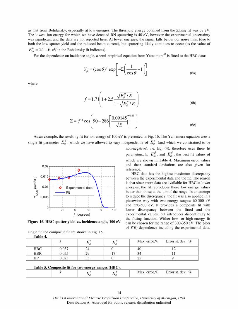
As an example, the resulting fit for ion energy of 100 eV is presented in Fig. 16. The Yamamura equation uses a
single fit parameter th
Eβ
, which we have allowed to vary independently of E
thE (and which we constrained to be
non-negative), i.e. Eq. (4), therefore uses three fit
parameters, k, th
Eβ
, and th
Eβ
, the best fit values of
which are shown in Table 4. Maximum error values
and their standard deviations are also given for
reference.
HBC data has the highest maximum discrepancy
between the experimental data and the fit. The reason
is that since more data are available for HBC at lower
energies, the fit reproduces these low energy values
better than those at the top of the range. In an attempt
to reduce the discrepancy, the fit was also applied in a
piecewise way with two energy ranges: 60-300 eV
and 350-500 eV. It provides a composite fit with
lower discrepancy between the fitted and the
experimental values, but introduces discontinuity to
the fitting function. Wither low- or high-energy fit
can be chosen for the range of 300-350 eV. The plots
of Y(E) dependence including the experimental data,
single fit and composite fit are shown in Fig. 15.
Table 4.
k E
thE
thE
β Max. error,% Error st. dev., %
HBC 0.037 24 0 40 12
HBR 0.055 29 17 34 11
HP 0.073 35 0 25 9
Table 5. Composite fit for two energy ranges (HBC).
k E
thE
thE
β Max. error,% Error st. dev., %
0 20 40 60 80 1000
0.005
0.01
0.015
0.02
β (degrees)
YQ
CM
(m
m3/C
)
Experimental data
Fit
Figure 16. HBC sputter yield vs. incidence angle, 100 eV

15
The 31st International Electric Propulsion Conference, University of Michigan, USA
Distribution A: Approved for public release; distribution unlimited
60-300 eV 0.038 23 0 29 9
350-500 eV 0.104 116 0 26 8
To capture differential sputter yield we also fit E* values using the second-order polynomial fit:
2 2
1 2 3 4 5 6*E c E c c E c E c cβ β β= + + + + + (7)
The fitting parameters are given in Table 6.
Table 6.
c1 c2 c3 c4 c5 c6
HBC 0.073 -0.53 0.0065 0.00037 0.0020 0.92
HBR -0.011 0.78 0.0034 0.00079 -0.014 -0.18
HP -0.011 0.78 0.0034 0.00079 -0.014 -0.18
Example of hemispheric differential sputter yield plots obtained using the experimental and fitted values of Y
and E* are shown in Fig. 17 and 18.
0
0.005
0.01
0.015
0.02
0.025
0
0.005
0.01
0.015
0.02
(a) (b)
Figure 17. Hemispherical plots of differential sputter yield for HBR, ion energy - 350 eV, incidence angle 45,
(a) – using the experimental values of Y, E*, (b) using fitted values of Y, E*. Units are mm3/C/sr.
0
0.005
0.01
0.015
0.02
0.002
0.004
0.006
0.008
0.01
0.012
(a) (b)
Figure 18. Hemispherical plots of differential sputter yield for HBR, ion energy - 500 eV, incidence angle 15,
(a) – using the experimental values of Y, E*, (b) using fitted values of Y, E*. Units are mm3/C/sr.
16
The 31st International Electric Propulsion Conference, University of Michigan, USA
Distribution A: Approved for public release; distribution unlimited
V. Conclusion
We report total and differential sputter yield measurements for three grades of BN (HBC, HBR, and HP) in the
energy range of 60-500 eV. Measurements have been performed using a QCM deposition sensor providing
differential sputter yield profiles of condensable particles. Total yields are found from the integrated profiles. Using
a four-grid source we have performed measurements of BN sputtering below 100 eV.
The numerical models, previously published experimental data, and our study of the QCM surface layer
composition indicate that sputtering is predominantly as atoms (with boron atoms depositing to the QCM, but not
nitrogen). This information is critical for interpretation of our QCM measurements and is also important for
interpretation of future laser diagnostics systems based on CRDS which will measure only boron contributions. In
terms of total BN sputter yields, we observe higher values relative to published data. Possible reasons for this are
discussed and are under ongoing investigation. In comparison to a representative refractory metal such as
molybdenum, we find similar volumetric yields for BN, though the corresponding BN mass- (or atomic-) based
yields are still ~5x lower due to the lower density of BN. For HBC grade BN, the threshold energy determined by
fitting experimental data is 24±6 eV. Preliminary data on the temperature dependence of the sputter yield are
reported for temperature up to 544oC.
Finally, we find that the fitted MZ profiles provide a reasonable description of the measured yields. The shapes
(E*/E values) for the three grades of BN are all relatively similar and show azimuthally symmetric behavior at
normal incidence and forward/backward sputtering features at oblique incidence.
There is a critical need in the EP community for low ion energy sputter measurements of BN, and the present
contribution is a step forward filling this gap. Upcoming and ongoing work aims to measure the BN sputtering over
a broader range of sputtering conditions and includes study of variation of BN sputter yields with temperature.
Acknowledgments
The authors would like to thank Air Force Research Labs (Edwards Air Force Base, CA) for funding support.
The authors also thank George Diehl and Caleb Blissett (Sigma Instruments) for help with the QCM measurement
system, Paul Wilbur, John Williams and Casey Farnell (Colorado State University) for initial development of the
QCM apparatus, and Cody Farnell (Colorado State University) for designing the four-grid ion optics.
References 1Betz, G. and Wien, K. “Energy and Angular Distributions of Sputtered Particles,” International Journal of Mass Spectrometry
and Ion Processes, Vol. 140, 1994, pp. 1-110. 2Tartz, M., Neumann, H., Fritsche, B., Leiter, H., and Esch, J., “Investigation of Sputter Behaviour of Ion Thruster Grid
Mmaterials,” 40th AIAA Joint Propulsion Conference (Ft. Lauderdale, FL), 2004, AIAA paper 2004-4114 3Kolasinski, R. D., “Oblique Angle Sputtering Yield Measurements for Ion Thruster Grid Materials,” 41st AIAA Joint Propulsion
Conference (Tucson AZ), 2005, AIAA paper 2005-3526. 4Kolasinksi, R. D., Polk J. E., Goebel D., and Johnson, L. J., “Carbon Sputtering Yield Measurements at Grazing Incidence,”
42nd AIAA Joint Propulsion Conference (Sacramento, CA), 2006, AIAA paper 2006-4337. 5Zoerb, K. A., Williams, J. D., Williams, D. D., and Yalin, A. P., “Differential Sputtering Yields of Refractory Metals by Xenon,
Krypton, and Argon Ion Bombardment at Normal and Oblique Incidences,” 29th International Electric Propulsion Conference
(Princeton, NJ), 2005, IEPC-2005-293. 6Yalin, A. P., Williams, J. D., Surla, V., Wolf, J., and Zoerb, K. A., “Azimuthal Differential Sputter Yields of Molybdenum by
Low Energy Ion Bombardment,” 42nd AIAA Joint Propulsion Conference (Sacramento, CA), 2006, AIAA paper 2006-4335. 7Yalin, A. P., Williams, J. D., Surla, V., and Zoerb, K. A., “Differential Sputter Yield Profiles of Molybdenum due to
Bombardment by Low Energy Xenon Ions at Normal and Oblique Incidence,” Journal of Physics D - Applied Physics, Vol. 40,
2007, pp.3194-3202. 8Polk, J. E., “An Overview of the Results from an 8200 Hour Wear Test of the NSTAR Ion Thruster,” 35th AIAA Joint
Propulsion Conference (Los Angeles, CA), 1999, AIAA paper 99-2446. 9Yalin, A. P., Rubin, B., Domingue, S. R., Glueckert, Z., and Williams, J. D., “Differential Sputter Yields of Boron Nitride,
Quartz, and Kapton Due to Low Energy Xe+ Bombardment,” 43rd AIAA Joint Propulsion Conference (Cincinnati, OH), 2007m
AIAA paper 2007-5314. 10Rubin, B., Topper, J. L., and Yalin, A. P., “Total and Differential Sputter Yields of Boron Nitride Measured by Quartz Crystal
Microbalance and Weight Loss”, 30th International Electric Propulsion Conference (Florence, Italy), 2007, IEPC-2007-074. 11Topper, J. L., Rubin, B., Farnell, C. C., and Yalin, A. P., “Preliminary Results of Low Energy Sputter Yields of Boron Nitride
due to Xenon Ion Bombardment,” 44th AIAA Joint Propulsion Conference (Hartford, CT), 2008, AIAA paper 2008-5092. 12Yalin, A. P., Surla, V., Farnell, C., Butweiller, M., and Williams, J. D., “Sputtering Studies of Multi-Component Materials by
Weight Loss and Cavity Ring-Down Spectroscopy,” 42nd AIAA Joint Propulsion Conference (Sacramento, CA), 2006. AIAA
paper 2006-4338.

17
The 31st International Electric Propulsion Conference, University of Michigan, USA
Distribution A: Approved for public release; distribution unlimited
13Chiplonkar, V. T. and Rane, S. R., “Dependence of Angular Distribution of Sputtering by Positive Ions from Metal Targets on
the Impact Angle,” Indian Journal of Pure and Applied Physics, Vol. 3, 1965, p. 161. 14Tsuge, H. and Esho, S. “Angular Distribution of Sputtered Atoms from Polycrystalline Metal Targets,” Journal of Applied
Physics, Vol. 52, 1981, pp. 4391-95. 15Wucher, A. and Reuter, W., “Angular Distribution of Sputtered Particles from Metals and Alloys,” Journal of Vacuum Science
and Technology A, Vol. 6, 1988, pp. 2316-18. 16Mannami, M., Kimura, K., and Kyoshima, A., “Angular Distribution Measurements of Sputtered Au atoms with Quartz
Oscillator Microbalances,” Nuclear Instruments and Methods, Vol. 185, 1981, pp. 533-37. 17Wickersham, C. E. and Zhang, Z. “Measurement of Angular Emission Trajectories for Magnetron-Sputtered Tantalum,”
Journal of Electronic Materials, Vol. 34, 2005, pp. 1474-79. 18Shutthanandan, V., Ray, P., Shivaparan, N., Smith, R., Thevuthasan, T., and Mantenieks, M., “On the Measurement of Low-
Energy Sputtering Yield Using Rutherford Backscattering Spectrometry,” 25th International Electric Propulsion Conference
(Cleveland, OH), 1997, IEPC-97-069. 19Mantenieks, M., Foster, J., Ray, P., Shutthanandan, S., and Thevuthasan, T., “Low Energy Xenon Ion Sputtering Yield
Measurements,” 27th International Electric Propulsion Conference (Pasadena, CA,) 2001, IEPC-01-309. 20Kundu, S., Ghose, D., Basu, D., and Karmohapatro, S. B., “The Angular Distribution of Sputtered Silver Atoms,” Nuclear
Instruments and Methods in Physics Research B, Vol. 12, 1985, pp.352-57. 21Surla, V. and Yalin, A. P., “Differential Sputter Yield Measurements Using Cavity Ring-Down Spectroscopy,” Applied. Optics,
Vol. 46, 2007, pp. 4057-64. 22Yalin, A. P., Tao, L., Yamamoto, N., Smith, T. B., and Gallimore, A. D., “Boron Nitride Sputter Erosion Measurements by
Cavity Ring-Down Spectroscopy,” 30th International Electric Propulsion Conference (Florence, Italy), 2007, IEPC-2007-075. 23Yim, J., “Computational Modeling of Hall Thruster Channel Wall Erosion,” Ph.D. Dissertation, Univ. of Michigan, Ann Arbor,
MI, 2008. 24Cheng, S. “Modeling of Hall Thruster Lifetime and Erosion Mechanisms,” Ph.D. Dissertation, Massachusetts Inst. of
Technology, Cambridge, MA, 2007. 25Ustarroz, J., Caro, I., Corengia, P., Garmendia, I., Marcos, J., Ahedo, E., and Gonzales del Amo, J., “Specific Laboratory
Testing Equipment & Methodology for Sputtering Tests of Electric Propulsion Materials,” 30th International Electric Propulsion
Conference (Florence, Italy), 2007, IEPC-2007-167. 26Rubin, B., Topper, J. L., and Yalin, A. P., (preprint) “QCM Based System for High-Sensitivity Differential Sputter Yield
Measurements,” in submission to Review of Scientific Instruments.. 27Farnell, C. C., Williams, J. D., Wilbur, P. J., “Numerical Simulation of Ion Thruster Optics,” 28th International Electric
Propulsion Conference (Toulouse, France,) 2003 IEPC-2003-073. 28 Zhang, J., Bhattachargee, S., Shutthanandan, V., and Ray, P. K. “Sputtering Investigation of Boron Nitride with Secondary
Ion and Secondary Neutral Mass Spectrometry,” Journal of Vacuum Science and Technology A, Vol. 15, 1997, pp. 243-7. 29Nikiporetz, E., Semenov, A., Shkarban, I., and Khartova, E., “Sputtering Process of BN Based Ceramic by the Flows of
Noncompensated Charge Plasma,” 30th International Electric Propulsion Conference (Florence, Italy), 2007 IEPC-2007-7. 30Garnier, Y., Viel, V., Roussel, J.-F., and Bernard, J., “Low-Energy Xenon Ion Sputtering of Ceramics Investigated for
Stationary Plasma Thrusters,” Journal of Vacuum Science and Technology A, Vol. 17, 1999, pp. 3246-54. 31Bachmann, L’ and Shin, J.J., “Measurement of the Sticking Coefficients of Silver and Gold in an Ultrahigh Vacuum,“ Journal
of Applied Physics, Vol. 37, 1966, pp. 242-6. 32http://srdata.nist.gov/xps/ 33Abgaryan, V. K., Mikheev, S. Yu., Prokofiev, M. V., Ryzhov, Yu. A., and Shkrban, I. I., “Mass Spectra of Particles Emitted
from Ceramic Surfaces Irradiated by Plasma Flows,” Bulletin of the Russian Academy of Sciences: Physics (Izvestiya Rossiiskoi
Akademii Nauk. Seriya Fizicheskaya), Vol. 70, 2006, pp. 879-82 (in Russian). 34Sigmund, P. “Theory of Sputtering I: Sputtering Yield of Amorphous and Polycrystalline Targets,” Physical Review, Vol. 184,
1969,pp. 383-416. 35Wehner, G. K. and Rosenberg, D., “Angular Distribution of Sputtered Material” Journal of Applied Physics, Vol. 31, 1960,
pp.177-9. 36Chini, T. K., Tanemura, M., and Okuyama, F., “Angular Distribution of Sputtered Ge Atoms by Low keV Ar+ and Ne+ Ion
Bombardment,” Nuclear Instruments and Methods in Physics. Research B , Vol. 119 ,1996, pp. 387-91. 37Yamamura, Y. and Muraoka, K., “Over-Cosine Angular Distributions of Sputtered Atoms at Normal Incidence”, Nuclear
Instruments and Methods in Physics Research B, Vol. 42, 1989, pp. 175-81. 38Yamamura, Y., “Contribution of Anisotropic Velocity Distribution of Recoil Atoms to Sputtering Yields and Angular
Distributions of Sputtered Atoms,” Radiation Effects, Vol. 55, 1981, pp. 49–55 . 39Yamamura, Y., “Theory of Sputtering and Comparison to Experimental Data,” Nuclear Instruments and Methods,” Vol. 194,
1982, 515–22 . 40Zhang, Z. L. and Zhang, L. “Anisotropic Angular Distributions of Sputtered Atoms,” Radiation Effects & Defects in Solids,
Vol. 159, 2004, pp. 301-7. 41Zhang, L. and Zhang, L.Z. “Anisotropic Energy Distribution of Sputtered Atoms Induced by Low energy Heavy Ion
Distribution,” Radiation Effects & Defects in Solids, Vol. 160, 2005, pp. 337-47. 42Yamamura, Y. and Tawara, H. “Energy Dependence of Ion-Induced Sputtering Yields from Monatomic Solids at Normal
Incidence,” Atomic Data Nuclear Data Tables, Vol. 62, 1996, pp.149-253.

18
The 31st International Electric Propulsion Conference, University of Michigan, USA
Distribution A: Approved for public release; distribution unlimited
43Yamamura, Y., Itikawa, Y., and Itoh, N. “Angular Dependence of Sputtering Yields of Monatomic Solids” Institute for Plasma
Physics Report, IPPJ AM-26, 1983. 44Doerner, R. P., Whyte, D. G., and Goebel, D. M., “Sputtering Yield Measurements During Low Energy Xenon Plasma
Bombardment,” Journal of Applied Physics, Vol. 93, 2003, pp. 5816-23. 45Bohdansky, J. A., “Universal Relation for the Sputtering Yield of Monatomic Solids at Normal Ion Incidence,” Nuclear
Instruments and Methods in Physics. Research. B, Vol. 2, 1984, pp. 587–91. 46Semenov, A. and Shkarban, I., “Ion Beam Sputtering of the Surfaces of Ion and Plasma Sources,” Rocket and Space
Engineering: Rocket Engines and Power Plants, No.3, 1991, pp. 42-53 (in Russian). 47Abashkin, V., Gorshkov, O., Lovtsov, A., and Shagaida, A., “Analysis of Ceramic Erosion Characteristic in Hall-Effect
Thruster with Higher Specific Impulse,” 30th International Electric Propulsion Conference (Florence, Italy), 2007, IEPC-2007-
133. 48Kim, V., Kozlov, V., Semenov, A., and Shkarban, I., “Investigation of the Boron Nitride Based Ceramics Sputtering Yield
Under it’s Bombardment by Xe and Kr Ions,” 27th International Electric Propulsion Conference (Pasadena, CA), 2001, IEPC-
2001-073. 49Khartov, S.A., Nadiradze, A.B., Shkarban,I.I., Zikeeva, Y.V., “SPT’s High Lifetime – Some Problems of Solution,” 29th
International Electric Propulsion Conference (Princeton University), 2005, IEPC-2005-62. 50Doerner, R.P., Krasheninnikov, S.I., Schmid, K., “Particle-Induced Erosion of Materials at Elevated Temperature”, Journal of
Applied Physics, Vol. 91, 2004, pp. 4471-4475.