Embed Size (px)
Citation preview

Toward the first D-band Point to multipoint wireless system field test
Claudio Paoloni1, Rupa Basu1 , Marcel Burhenn2, Maruf Hossain9, Daniel Huebsch2, Viktor Krozer3, Trung Le2, Rosa Letizia1, Ernesto Limiti5, François Magne4, Marc Marilier6, Antonio Ramirez7, Jeevan M Rao1, Giacomo
Ulisse3, Borja Vidal8, Hadi Yacob9,
1 Engineering Department, Lancaster University, Lancaster, United Kingdom, LA1 4YW email: [email protected] 2 Hübner GmbH & Co. KG, Kassel 34123, Germany
3 Goethe University Frankfurt/M, Frankfurt 60323, Germany 4When Ab, Paris, France
5 University of Rome, Tor Vergata, Rome, Italy 6 OMMIC S.A.S., Limeil Brevannes, 94453, France
7 Fibernova Systems, Valencia 46022, Spain 8 Universitat Politècnica de València, Valencia 46022, Spain
9 Ferdinand-Braun-Institut, Leibniz-Institut für Höchstfrequenztechnik, Berlin, Germany
Abstract— The European Commission Horizon 2020 ULTRAWAVE “Ultra capacity wireless layer beyond 100 GHz based on millimeter waves” is in the final stage of development. The first ever field test of a D-band point to multipoint wireless system will be performed in a real environment. The ULTRAWAVE wireless system comprises a D-band Transmission Hub to produce a 30 degree sector with 600 m radius with multi gigabit per second data rate and a number of compact D-band terminals. The terminals will be distributed at different distances from the transmission hub to recreate real deployment condition. The paper describes the latest update on the development of the ULTRAWAVE systems and the field test set up.
Keywords— D-band; point to multipoint, wireless, terminals, TWT, transmissio hub, 6G, 5G, backhaul
I. INTRODUCTION Point to multipoint distribution (PmP) with high capacity at
D-band (141 - 148.5 GHz) is the ambitious aim of the European Commission Horizon 2020 ULTRAWAVE “Ultra capacity wireless layer beyond 100 GHz based on millimeter waves” [1]-[4]. The advantages of point to multipoint distribution in comparison to other modalities, such as point to point (PtP), beam steering or multiple beam are the flexibility of frequency allocation, easy alignment of terminals, low Total Cost of Operation (TCO), small footprint of front ends, easy reconfiguration of the network to adapt to new traffic needs, low latency, low complexity of the radio and the antenna system ( [5] – [7]).
Differently, from the other distribution modalities that use high gain high directivity antennas, PmP distributes the signal over a wide area by a wide beam, generated by a low gain antenna. The reduction in gain with respect to typical PtP antennas (>40 dBi) is in the order of 20 dBi, that have to be
compensated, for achieving a same range as an equivalent PtP link, by higher transmission power.
Above 100 GHz, solid state power amplifiers have limited output power. Specifically, at D-band, state of the art power amplifiers can provide about 20 dBm output power [8] - [10]. This power does not satisfy the link budget for wide beam hundreds of meters long, providing sufficient signal to noise ratio (SNR) for operation in real environment.
This is the main reason why it is so challenging to enable PmP wireless distribution above 100 GHz. The development and introduction of Traveling Wave Tubes (TWTs) as power amplifier has opened new opportunities to enable sub-THz PmP wireless system [11]. TWTs can provide output power in the range of 40 dBm at D-band, over more than 10 GHz bandwidth [12], [13]. That performance permits to enable wide beam to transport tens of Gb/s data rate, with more than 100 Gb/s/km2 area capacity, with high SNR supporting up to 64QAM over radial sector with 600 m or more radius.
The ULTRAWAVE wireless concept is to distribute internet at high capacity by sectors in PmP deployed where needed. Each sector is generated by a transmission hub. Terminals are distributed over the sector to serve base stations at ground level, with a flexible allocation of channels.
The transmission hub and the terminals at D-band use a simple Radio topology. This is an important design aspects, since the electronics at D-band is very challenging, not only in terms of mmMICs (millimeter wave Monolithic Integrated Circuits) but also interconnections, transitions, assembly.
The ULTRAWAVE project has developed the full D-band PmP wireless system, including the mmMIC chipset, antennas, filters,
The work has received funding from the European Union’s Horizon 2020 research and innovation programs under grant agreement no 762119. This work reflects only the author view’s and the Commission is not responsible of any use that may be made of the information it contains.

motherboards, housings and TWT. The project is in advanced stage of completion with the Transmission Hub and the Terminals almost fully fabricated and tested at laboratory level at the time of the submission of this paper
A field test in real environment is scheduled at the end of May 2021 in the infrastructure available at the campus of the Politechnica Universitat of Valencia in Spain.
In the following, the latest results of the projects and a description of the field test will be discussed.
Section II will give an overview of the ULTRAWAVE PmP D-band system, Section III describes the Transmission Hub, Section IV describes the Terminal and Section V the setup for the field tests.
II. ULTRAWAVE D-BAND PMP CONCEPT The ULTRAWAVE system is an end-to-end sub-network
based on a point to multipoint wireless distribution network at D-band (141 - 148.5 GHz) connected to the fiber infrastructure directly at a point of presence or by point to point very high capacity fronthaul at G-band (275 - 305 GHz) in form of mesh network with redundancy. The G-band wireless system consists of a photonic transmitter connected to a TWT with sufficient power to satisfy the link budget to provide 30 Gb/s over 500 -600 m range.
In this paper, the PmP at D-band will be discussed. The PmP backhaul distribution system at D-Band uses sector’s Transmission Hub to feed Terminals, several sectors can be deployed for convenient coverage. Substantial challenges pertain to the gain of amplifiers together with their linearity, the interconnection losses, image and LO leakage filtering, synthesizer and LOs distribution and finally to mmMIC and TWT fabrication and performances.
A. Transmission Hub The Transmission Hub comprises an in-door unit IDU with
switch aggregation and stack of modems creating a multiplex, and an out-door unit ODU comprising the radio with the TWT as power amplifier, the receiver and the sector antennas.
1) D-band Transmission Hub Indoor Unit (Multiplex) In a PmP distribution system, the Transmission Hub
multiplex provides the total capacity which is delivered and collected to and from the Terminals. The Terminals have the purpose of feeding small cells at lower capacity at street level. The wireless networking standard 802.11ad was firstly considered. However, it has been assessed that the standard 802.11ac wave 2, with 80MHz and 160MHz channels is more suitable to match the small cell’s demand with the best suppleness. Considering the range-throughput compromise, dedicated capacities could be provided to a dozen of small cells with 120 to 480 Mbps each depending on the demand. With this configuration, a total capacity of 4 Gigabits per sector can be a typical service (for instance with 8 channels of 160 MHz in 16QAM). The spectrum required for these operating conditions is around 1.5 GHz.
The schematic of the Transmission Hub is shown in Fig.1. Several 802.11ac modems are combined by RF/combiner splitter to feed the radio ODU. The connection is on N-SMA
cables or on fiber optics if the ODU is placed far from the IDU (e.g., ODU on the roof and IDU one or two floor below). The modem with RJ45 plugs to the GbE router/switch, then to the combiners and splitters for the radio multiplex and TOSA (Transmitter Optical Sub-Assembly) and ROSA (Receiver
Fig. 1 Block diagram of the Transmission Hub including the IDU and the ODU
Fig. 2 Transmission Hub rendering
Optical Sub-Assembly) for optical transmission, so called RoF (Radio over Fiber).
2) D-band Transmission Hub Outdoor Unit The outdoor unit of the Transmission Hub [4] includes the
motherboard, the TWT and the low gain horn antennas (20 dBi). Fig. 2 shows the internal arrangement in the housing. The motherboard includes the D-band radio with conversion at W-band and a second level of conversion at Q-band to bring the signal at the frequency of modems, C-band (5 - 6 GHz). The TWT is placed in correspondence of a heating extraction unit connected to the outside of the housing. The motherboard is also connected to the housing wall for heat dissipation. The motherboard is very compact, about 24 x 18 x 2 cm. The housing is over-dimensioned for prototyping purposes. With a space optimization the TH can be very compact with a size in the range of 40x25x20 cm including all necessary power supplies apart from a 24V external DC supply.
To consider that a single TH can provide over one sector up to 30 Gb/s distributed in tens of channels and it is equivalent to more than 20 E-band PtP links available on the market. This is a relevant result from the Total Cost of Operation (TCO) that will make competitive the ULTRAWAVE system.
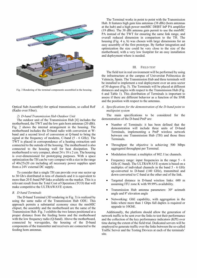
B. D-band Terminals The D-band Terminal (3D rendering in Fig. 3) is realized by
using the same radio of the Transmission Hub ODU. This approach permits a substantial economy since the mmMIC chipset, the assembly and the motherboard are the same of the Transmission Hub. Fig. 3 exhibits the two lenses positioned at a proper distance from the feeding horns and the motherboard with the low frequency radio (Q-band). Above the motherboard, connected by waveguides, the housing of the D-band components of the transmitter and receivers are connected to the feeding horn antennas.
The Terminal works in point to point with the Transmission Hub. It features high gain lens antennas (38 dBi) (horn antennas at the hub) and a high power mmMIC DHBT InP PA amplifier (19 dBm). The 38 dBi antenna gain permit to use the mmMIC PA instead of the TWT for ensuring the same link range, and overall reduced dimension in comparison to the TH. The housing (Fig. 4 a, b) was chosen with large dimensions for an easy assembly of the first prototype. By further integration and optimization the size could be very close to the size of the motherboard, with a very low footprint for an easy installation and deployment where is needed.
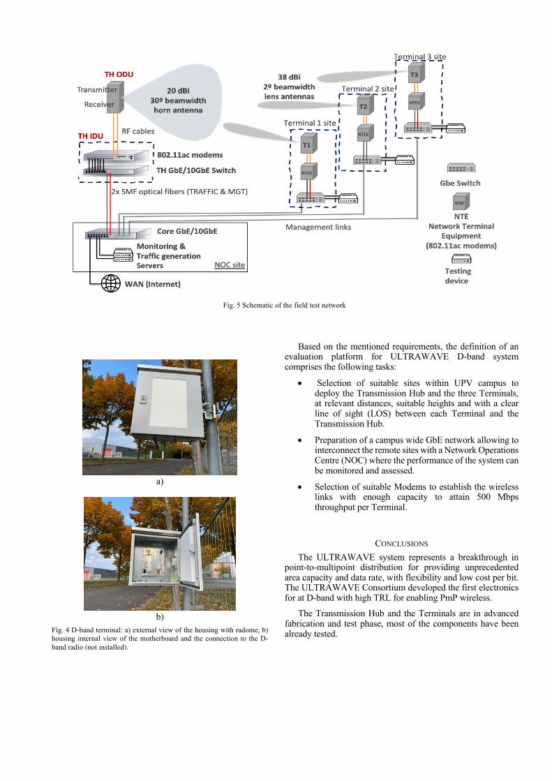
III. FIELD TEST The field test in real environment will be performed by using
the infrastructure at the campus of Universitat Politecnica de Valencia, Spain. The Transmission Hub and three terminals will be installed to implement a real deployment over an area sector of 30 degrees (Fig. 5). The Terminals will be placed at different distances and angles with respect to the Transmission Hub (Fig. 6 and Table 1). This distribution of Terminals is important to assess if there are different behavior as a function of the SNR and the position with respect to the antennas.
A. Specifications for the demonstration of the D-band point to multipoint system The main specifications to be considered for the
demonstration of the D-band PmP are:
• Number of Terminals: it has been defined that the demonstration will include three units of D-band Terminals, implementing a PmP wireless network between one Transmission Hub (TH) and those three Terminals.
• Throughput: the objective is achieving 500 Mbps aggregated throughput per Terminal.
• Modulation format: a multiplex of 802.11ac channels.
• Frequency range: input frequencies in the range 5 - 6 GHz (C-band). The ULTRAWAVE system is based on a multiplex of individual channels in the band 5 - 6 GHz up-converted to D-band (140 GHz), transmitted and down-converted to C-band at the other end of the link.
• Targeted distance in D-band wireless links: 600 m assuming ITU zone K with 99.99% availability.
• Transmission Hub antenna parameters: 30º azimuth angle and 8º elevation angle
• Networking: GbE capability, with aggregation in the links where more than 1 Gbps full duplex is required or upgrade to 10GbE.
Additionally, the platform should allow the generation of network traffic to be sent over the links to test their performance and the collection of the key performance indicators (KPI) over time during the extent of the field trial. Dedicated servers will be employed to generate traffic over the links between the so-called Traffic Server and the Testing Devices at each of the terminals’ site.
Fig. 3 Rendering of the terminal components assembled in the housing.
Based on the mentioned requirements, the definition of an evaluation platform for ULTRAWAVE D-band system comprises the following tasks:
• Selection of suitable sites within UPV campus to deploy the Transmission Hub and the three Terminals, at relevant distances, suitable heights and with a clear line of sight (LOS) between each Terminal and the Transmission Hub.
• Preparation of a campus wide GbE network allowing to interconnect the remote sites with a Network Operations Centre (NOC) where the performance of the system can be monitored and assessed.
• Selection of suitable Modems to establish the wireless links with enough capacity to attain 500 Mbps throughput per Terminal.
CONCLUSIONS The ULTRAWAVE system represents a breakthrough in
point-to-multipoint distribution for providing unprecedented area capacity and data rate, with flexibility and low cost per bit. The ULTRAWAVE Consortium developed the first electronics for at D-band with high TRL for enabling PmP wireless.
The Transmission Hub and the Terminals are in advanced fabrication and test phase, most of the components have been already tested.
Fig. 5 Schematic of the field test network
a)
b)
Fig. 4 D-band terminal: a) external view of the housing with radome, b) housing internal view of the motherboard and the connection to the D-band radio (not installed).

REFERENCES
ULTRAWAVE website [Online]. Available: http://ultrawave2020.eu Paoloni, C, Boppel, S, Krozer, V, Quang, TL, Letizia, R, Limiti, E,
Magne, F, Marilier, M, Ramirez, A, Vidal, B & Zimmerman, R 2019, Technology for D-band/G-band Ultra Capacity Layer, 2019 European Conference on Networks and Communications (EuCNC). IEEE, pp. 209-213, EUCNC, Valencia, Spain, 18/06/19.
F. Magne, A. Ramirez, C. Paoloni, “Millimeter Wave Point to Multipoint for Affordable High Capacity Backhaul of Dense Cell Networks”, IEEE Wireless Communications and Networking Conference 2018, WCNC 2018, Barcelona, Spain, April 2018.
M. Hossain, V. Krozer, T. Le, R. Basu, R. Letizia, E. Limiti, F. Magne, M. Marilier, A. Ramirez, J. M Rao, G. Ulisse, B. Vidal, H. Yacob, C. Paoloni,“ D-band Transmission Hub for Point to MultiPoint Wireless Distribution”, European Microwave Week 2020, virtual
R. Taori and A. Sridharan. "Point-to-multipoint in-band mmwave backhaul for 5G networks,", IEEE Communications Magazine, pp. 195-201, January 2015.
J. Shi, L. Lv, Q. Ni, H. Pervaiz and C. Paoloni, "Modeling and Analysis of Point-to- Multipoint Millimeter Wave Backhaul Networks," in IEEE Trans. Wireless Commun., vol. 18, Jan. 2019, pp. 268-285.
C. Paoloni, F. Magne, F. André, J. Willebois, Q. T. Le, X. Begeaud, G. Ulisse, V. Krozer, R. Letizia, M. Marilier, A. Ramirez, R. Zimmerman, “Transmission Hub and Terminals for Point to Multipoint W-band TWEETHER System”, European Conference on Networks and Communications, EuCNC 2018, Ljubljana, Slovenia, June 2018.
Hua Wang, Tzu-Yuan Huang, Naga Sasikanth Mannem, Jeongseok Lee, Edgar Garay, David Munzer, Edward Liu, Yuqi Liu, Bryan Lin, Mohamed Eleraky, Sensen Li, Fei Wang, Amr S. Ahmed, Christopher Snyder, Sanghoon Lee, Huy Thong Nguyen, and Michael Edward Duffy Smith, "Power Amplifiers Performance Survey 2000-Present," [Online]. Available: https://gems.ece.gatech.edu/PA_survey.html
Dhillon, S. S. et. al, “The 2017 terahertz science and technology roadmap”, J. Phys. D: Appl. Phys. 2017, 50, 043001.
T. Nagatsuma et al. Advances in terahertz communications accelerated by photonics, Nature Photonics 10, 371-379 (2016)
C. Paoloni, D. Gamzina, R. Letizia, Y. Zheng and N. C. Luhmann Jr., “Milimeter Wave Traveling Wave Tubes for the 21st Century”, J. Electromagn. Wav. Appl., Dec. 2020. 10.1080/09205071.2020.1848643
R.Basu, L. R. Billa, R. Letizia, C. Paoloni, “Design of sub-THz traveling wave tubes for high data rate long range wireless links”, 2018 Semicond. Sci. Technol. 33 124009
R.Basu, L. R. Billa, R. Letizia, C. Paoloni, “Design of D-band Double Corrugated Waveguide TWT for Wireless Communications “, Proc. IEEE 20th Int. Vac. Electron. Conf., Busan, South Kores, April. 2019
Fig. 6 Position and distance of the D-band Terminals from the point of view of the Transmission Hub (Google Earth image)’
TABLE I Installation details (height, distance, angle) between TH and Terminals
1, 2 and 3
Site name Height Delta
height vs TH
Distance from TH
Azimuth angle
from TH
TH 27 m - - - Terminal
1 20 m -7 m 300 m 270º
Terminal 2 27 m 0 m 450 m 277º
Terminal 3 28 m +1 m 500 m 280º