Embed Size (px)
DESCRIPTION
Direct injected gasoline engine research.
Citation preview

400 Commonwealth Drive, Warrendale, PA 15096-0001 U.S.A. Tel: (724) 776-4841 Fax: (724) 776-5760
SAE TECHNICALPAPER SERIES 2000-01-0530
Research and Development of a New DirectInjection Gasoline Engine
Makoto Koike and Akinori SaitoToyota Central R&D Labs., Inc.
Terutoshi Tomoda and Yasuhiro YamamotoToyota Motor Corp.
Reprinted From: Direct Injection SI Engine Technology 2000(SP–1499)
SAE 2000 World CongressDetroit, MichiganMarch 6–9, 2000

The appearance of this ISSN code at the bottom of this page indicates SAE’s consent that copies of thepaper may be made for personal or internal use of specific clients. This consent is given on the condition,however, that the copier pay a $7.00 per article copy fee through the Copyright Clearance Center, Inc.Operations Center, 222 Rosewood Drive, Danvers, MA 01923 for copying beyond that permitted by Sec-tions 107 or 108 of the U.S. Copyright Law. This consent does not extend to other kinds of copying such ascopying for general distribution, for advertising or promotional purposes, for creating new collective works,or for resale.
SAE routinely stocks printed papers for a period of three years following date of publication. Direct yourorders to SAE Customer Sales and Satisfaction Department.
Quantity reprint rates can be obtained from the Customer Sales and Satisfaction Department.
To request permission to reprint a technical paper or permission to use copyrighted SAE publications inother works, contact the SAE Publications Group.
No part of this publication may be reproduced in any form, in an electronic retrieval system or otherwise, without the prior writtenpermission of the publisher.
ISSN 0148-7191Copyright © 2000 Society of Automotive Engineers, Inc.
Positions and opinions advanced in this paper are those of the author(s) and not necessarily those of SAE. The author is solelyresponsible for the content of the paper. A process is available by which discussions will be printed with the paper if it is published inSAE Transactions. For permission to publish this paper in full or in part, contact the SAE Publications Group.
Persons wishing to submit papers to be considered for presentation or publication through SAE should send the manuscript or a 300word abstract of a proposed manuscript to: Secretary, Engineering Meetings Board, SAE.
Printed in USA
All SAE papers, standards, and selectedbooks are abstracted and indexed in theGlobal Mobility Database

1
2000-01-0530
Research and Development of a New Direct InjectionGasoline Engine
Makoto Koike and Akinori SaitoToyota Central R&D Labs., Inc.
Terutoshi Tomoda and Yasuhiro YamamotoToyota Motor Corp.
Copyright © 2000 Society of Automotive Engineers, Inc.
ABSTRACT
A new stratified charge combustion system has beendeveloped for direct injection gasoline engines. Thespecial feature of this system is employment of a thin fan-shaped fuel spray formed by a slit nozzle. The stratifiedmixture is produced by the combination of this fan-sprayand a shell-shaped piston cavity. Both under-mixing andover-mixing of fuel in the stratified mixture is reduced bythis system. This combustion system does not requiredistinct charge motion such as tumble or swirl, whichenables intake port geometry to be simplified to improvefull load performance. The effects of the new system onengine performance at part load are improved fuelconsumption and reduced smoke, CO and HC emissions,obviously at medium load and medium engine speed. HCemissions at light load are also improved even with highEGR conditions.
INTRODUCTION
The distinctive feature of recent direct injection (DI)gasoline engines is to mix various operating regimes[1]~[3]. The engines are operated in stratified mode atpart load and homogeneous mode at or near full load.Charge stratification is achieved by injecting fuel duringthe compression stroke to provide a mixture cloud aroundthe spark plug. This enables stable combustion to beachieved while the overall mixture is ultra lean. Fuelconsumption is improved by reducing pumping loss andheat losses. On the other hand, homogeneous mixturesare achieved by injecting fuel during the induction stroke.Full load performance is improved more than PFI (PortFuel Injection) engines, because charge cooling withinjection improves volumetric efficiency and knockcharacteristics.
Besides this strategy, a strategy to employ stoichiometricoperation even at part load is also taken intoconsideration [4],[5]. Absence of liquid fuel in the intakeport and availability of conventional three-way-catalystgive an excellent potential to reduce pollutant emissions.
Higher compression ratio and engine down sizing enablevehicles to reduce fuel consumption.
Thus, DI gasoline engines have very attractive potentialfor improving gasoline engine’s advantage of powerdensity, and for improving their disadvantage ofincreased fuel consumption at part load. Recentdevelopments of fuel systems, engine control systems,after-treatment systems and combustion systems havegreatly contributed to the realization of this DI gasolineengine development [1]. Some automotive companies,including TOYOTA, have already introduced production DIgasoline engines [1]~[3].
Judging from these considerations, DI gasoline enginesare promising for passenger cars. Studies of mixturepreparation and combustion in DI gasoline engines havebeen increased recently, with stratified combustion beinga major reason for engine research and development.
As combustion starts with spark discharge and flamepropagation through the prepared mixture, the state ofthe mixture at the spark timing is one of the mostimportant factors for better engine performance.Combustion systems for stratified mixture should bedeveloped to operate well under homogeneousconditions as well as for good stratification. Robustnessagainst varying engine loads and engine speeds are alsoimportant. TOYOTA has previously developed acombustion system, consisting of a high-pressure swirlfuel injector, involute concave piston and helical intakeport with swirl control valve in 1996 [1]. Further studieshave derived a new concept to improve both full load andpart load performances. This paper reportsconsiderations to requirements of mixture preparation, anew combustion system and test engine performance.
LEADING COMBUSTION SYSTEMS SO FAR
Spray characteristics are the major factor for control ofmixture preparation. In addition to this, chambergeometry (piston, cylinder head) and charge motion arealso utilizable factors for mixture preparation. Figure 1

2
shows the classification of leading combustion systemsproposed recently.
The combustion systems that have come into practice,apply charge motion, piston geometry and swirl nozzlecone-sprays for stratified mixture preparation [1]~[3].Figure 2 shows one of these combustion systems [1].Since engines for passenger cars must have stablecombustion in any condition, ways of not injecting fueldirectly toward the spark plug are adopted. Fuel isinjected once toward the piston cavity and is guided bypiston wall to the spark plug with the assistance ofcharge motion. Vaporization and mixing of the fuel withair occur during this process. This concept requiresintake port modification or a flow control valve togenerate charge motion, as well as a piston with cavity.Although these requirements are not favorable for idealhomogenous operation, there are some advantages forstratified operation. Fuel behavior during the mixturepreparation period can be influenced in various ways bypiston cavity geometry and charge motion control.Regulation of mixture position by the cavity wall is alsouseful for stable combustion. Combustion systems of thiskind are proposed by many companies and researchfacilities [6],[7].
Figure 1. Classification of Combustion System
Two other methods that do not require special pistongeometry for stratified mixture preparation have beenproposed. One method is charge motion transport of fuelto the spark plug. Fuel is vaporized and mixes with air onits way to the spark plug. A swirl-based system isproposed in the past [8]. Recently, a tumble-basedsystem has been proposed by FEV [9]. Although theshape of the piston of those systems is thought to befavorable for homogenous operation, requirements forstrong charge motion seem to be against full loadperformance. Besides this, test engine results show [9]that combustion stability, including misfiring, seems to bea problem. Another is the jet-controlled method In whichthe spark discharges directly into the spray jet [10]. Fewmodifications from current PFI engines are very
attractive. However, the short distance between theinjection nozzle and spark plug, and short intervalsbetween injection and spark discharge cause problemsfor spark plug durability and soot generation, because itis difficult to avoid the existence of many fuel dropletsaround the spark plug. Besides this, previous reportsshow that engine performance is sensitive to the injectionand ignition timings, and are affected by the pistongeometry [10]. Another system using an air-assistedinjector is also proposed by Orbital [11].
Figure 2. Conventional Combustion System
REQUIREMENTS OF MIXTURE PREPARATION
STRATIFICATION UNDER LOWER CHARGEMOTION – Almost all the combustion systems havehigher demands for charge motion than PFI engines toprepare stratified mixtures. Since the cone-spray formedby a swirl nozzle has weak penetration, the role of chargemotion to transport fuel to the spark plug is veryimportant. However, special port geometry or ports withflow control valves increase flow losses to no smallextent. So, the theoretical benefits of DI gasoline enginesfor improving full load performance cannot be fullyutilized. Further, distinct charge motion increases heatlosses to wall, preventing fuel consumption from beingmore improved. These disadvantages are notable athigher engine speed. Consequently, stratified combustionsystems without the assistance of distinct charge motionis required to improve both full load performance and partload performance at middle and high engine speeds.
DISPERSION OF FUEL AND HOMOGENIZATION INSTRATIFIED MIXTURE – Flame propagation isimportant for recent DI gasoline engines during stratifiedoperation, where the air/fuel ratio of the mixture shouldbe within the flammable limits of the propagation. It isusually thought to be important for the fuel not to bedispersed, because lean mixtures are difficult to burn,and have resulted in light load HC emissions that havebeen one of the major problems of DI gasoline engines.

3
The state of the mixture preparation in the conventionalcombustion system was examined. The tested systemwas the swirl-based system with cone-spray [1]. Figure 3shows the ratio of unburned fuel in the HC emissionsunder stratified operation, analyzed by gaschromatograph. Almost 90% of HC emissions areunburned fuel at light load. The rest of those are partiallyburned HC. The ratio of unburned fuel is more than 80%at medium load even in the operation with EGR. Theseresults indicate that most of HC emissions are from over-diluted fuel or isolated fuel torn into pieces that is due toover-dilution. This confirms the importance of not formingan over-lean mixture.
Figure 3. Ratio of Unburned Fuel in HC Emissions
Figure 4. Flame in Stratified Operation
Conversely, as the stratified mixture stays locally under-mixed, the fuel should be mixed well with air at this point.Figure 4 shows a flame image of stratified combustion inthe conventional DI gasoline engine. The blue and yellowflames suggest flame propagation throughheterogeneous air/fuel ratio. Yellow flame shows theunder-mixing of fuel. Although this is the result of fuelstratification for reliable inflammation under ultra leanoperation and reduction of over-diluted fuel, combustionin the rich mixture is undesirable because of a significantamount of incomplete combustion products. As most ofthese products are oxidized during the expansion andexhaust stroke, many incomplete combustion products
do not leave to the end. The problem is that the amountof heat released near TDC decreases because of heatloss due to incomplete combustion. These phenomenaare notable during conditions where the engine isoperated under higher load or higher engine speed,preventing fuel consumption from being more improved.
Figure 5 shows the effects of mixture preparation period(τmp) on engine performance at medium load. The τmp isthe period from the start of injection until spark discharge.HC emissions increase as τmp increases, becausemixing of fuel with air progresses. However, fuelconsumption (ISFC) decreases. The reason is that longτmp decreases rich mixture formation and increasescombustion efficiency near TDC. This is confirmed by thefact that ratio of heat release {R.H.R., (integration of heatrelease rate)/(heating value of fuel)}, that is to say themaximum integral value of heat release rate, increases inproportion to τmp.
Figure 5. Effects of Mixture Preparation Period
Thermodynamic considerations indicate that R.H.R doesnot decrease even if flame propagates through a fuel-richmixture, as long as burned gases mix with the surroundingair quickly like the diesel combustion process. However,mixing with air in DI gasoline engines progresses slowerthan the case of diesel engines. According to the theory ofmomentum [12], the amount of air induced into the fuel jetcan be calculated by equation (1).
(1)
Although the equation (1) is developed for a diesel spray,it is thought to be available to high-pressure gasolinespray because of fine droplets. It has been validated bycomparison between calculated spray lengths by thistheory and experimental results. Figure 6 shows thecomparisons of various types of sprays. The tested swirlnozzle forms solid cone spray. The calculated spraylengths give good agreement with the results of

4
experiment, showing that equation (1) is valid for DIgasoline sprays.
Figure 6. Comparisons of Spray Length
Figure 7. Comparison of Air Induction Speed
Figure 7 shows the contour lines of the numerical valuesof the underlined portion of the equation (1). It shows theeffects of air density and spray jet speed. The larger thevalue is, the larger the air induction speed becomes.Circles in the figure show each DI engine’s characteristic.The air induction speed of DI gasoline engines is from 1/3 to 1/5 of the case of DI diesel engines. It is thought thatthe large period from start of injection to spark advance isnot only due to the fuel travel to the spark plug, but alsofrom slow mixing speed. Slow mixing of fuel with airimplies slow mixing of burned gases with air.
The above shows that fuel should be mixed well beforespark discharge, to get high combustion efficiency afterflame propagation. It is particularly important at higherload and higher speed because the permissible time formixture preparation is short.
NEW COMBUSTION SYSTEM
The aims of the new combustion system are:
• Mixture preparation without depending on distinctcharge motion
• Decreased under-mixing and over-mixing of fuel, androbustness against varying engine loads and enginespeed
As mentioned previously, most of the combustionsystems prepare stratified mixtures with charge motion.One of the differences in mixture preparation with orwithout charge motion seems to be engine speedresponse. Since present fuel systems are unable tocontrol fuel pressure like diesel fuel systems, spraycharacteristics are fundamentally independent to enginespeed. On the other hand, the time allowed for mixturepreparation decreases in proportion to engine speed.Consequently, there are some differences in mixturepreparation with engine speed. The differences areinvestigated from the point of view of spray penetrationand fuel dilution.
Figure 8 shows the typical situation of mixturepreparation with and without charge motion control. Eachline in the figure represents differing engine speeds. Asthe required travel distance of fuel is thought to beindependent on engine speed, fuel must travel faster ortraveling time must be increased if engine speedbecomes high. Faster fuel delivery can be achieved bycharge motion control, because charge motion increaseswith the engine speed. However, induced air into thespray seems to be unchanged. Far from that, a decreaseof induced air is conceivable because of lower relativevelocity, causing under mixing at higher engine speed.
Figure 8. Influences of Charge Motion

5
Increased travelling time can be achieved by advance ofinjection timing. Although the required crank angle formixture preparation becomes longer, mixing with air isensured. It is important for robustness to keep fueltransfer and mixing with air well balanced. The conceptwithout charge motion has the ability to meet thisrequirement. Piston movement, intervention of piston walland differences in turbulence don’t make this simple inpractice. However, it is well understood that mixturepreparation without charge motion has potential for notonly managing both stratified and homogeneousoperations well, but also for improving the robustnessagainst the engine speed.
The new concept without charge motion requires differentspray characteristics as before. Suitably large penetrationand high mixing ability of spray are needed for therequired injection timing not to advance too far at higherengine speed. The cone-sprays used in conventional DIgasoline engines are currently suitable for ultra leanstratified operation at low load because of itscharacteristic of contracting in the high ambient pressure[13]~[15]. In summary, a cone-spray is not suitable forthis new concept for the following:
Figure 9. Combustion System
• The contracting characteristic means that fuel movesto the inside of the spray. Fuel distributions arebelieved to be fuel-rich inside and fuel-lean outside inthe case of late injection. HC emissions and cycle-by-cycle variation of combustion increase greatly ifinjection timing is advanced to eliminate under-mixing of fuel.
• Adequate dispersion of fuel is hard to realize athigher load and higher engine speed because of thecontracting characteristic.
• Large spray angles make penetration small. Itrequires charge motion assistance.
So, a new combustion system is developed using a fan-shaped spray. Figure 9 shows the outline of this system.The system puts fan-spray characteristics to practicaluse. The characteristics are:
• A thin, fan shape to enable fuel to be well dispersedand to mix with air uniformly.
• Small side view angle enables the fuel to move fasterthan cone spray.
Fuel is injected toward the piston crown, on which a shellshaped cavity is made for the spray to be rolled up nearthe spark plug.
MIXTURE PREPARATION AND COMBUSTION
Spray Characteristics – The fan-spray is formed by a slitnozzle of which the shape is rectangular and longer sidesare diverged from the inside to the outside. Shorter sidesof the tested nozzles are from 0.1mm to 0.2. Figure 10shows the schematic drawing of the slit nozzle. Figure 11shows an example of a fan-spray. Concentric circles ofspray are observed in a front view, and a thin spray isobserved in a side view. A leading slug of liquid, which isone of the defects of swirl nozzle, is not observed at all.
Figure 10. Slit Nozzle
The new combustion system requires two importantspray characteristics. The first is homogeneity of fueldistribution in a spray. Figure 12 shows line-of-sight fueldistributions that are measured from the intensity of lightthrough the spray [16]. It shows that fuel mixes with airequally toward the downstream of the spray tohomogenize fuel concentration especially at high ambientpressure. It keeps fuel from under-mixing in stratifiedoperation. Another characteristic observed is that theambient pressure does not change the spray angle in afront view, but the other spray angle (in a side view)becomes large as ambient pressure increased.
Figure 11. Image of Fan Spray

6
Figure 12. Fuel Distribution
The second characteristic is spray penetration to movethe spray towards the spark plug. The fan shape is morefavorable for large penetration than a cone-spray. Figure13 shows the effect of spray angle on spray penetration ineach case for a cone-spray and fan-spray. The sprayangle of the fan-spray is the larger one. The line in thefigure shows the border of the spray angle that forms thesame penetration for each spray. These results arecalculated from the theory of momentum [12]. The cone-spray is assumed as a solid cone. This figure shows thatthe fan-spray has larger penetration than a cone-spray forthe same spray angle. The difference becomes greater asthe spray angle becomes large. Although it may bedifficult to compare fan-sprays and cone-sprays formed bya swirl nozzle (because cone-sprays contract in highambient pressure or its shape can breakdown),experimental results show that the spray lengths of a fan-spray (spray angle:60°) and a cone-spray (sprayangle:30°) formed by swirl nozzle are almost the same, asshown in figure 14. It is as same as the results of figure13. Since the cone-angle of a swirl nozzle is usually morethan 40° in most DI gasoline engines, spray penetration ofa fan-spray is always larger than a cone-spray.
Figure 13. Comparison of Spray Length
Figure 14. Spray Length
An another important spray characteristic is the dropletsize. The SMD (Sauter Mean Diameter) values of thedroplets are measured by laser diffraction. Table 1 showsthe average SMD at 40mm downstream from the nozzle.The results show that the slit nozzle provides highlyatomized fuel spray.
Mixture Preparation – Mixture preparation in the cylinder,calculated by 3-D CFD [17], is shown in figures 15 and16. Figure 15 shows velocity and borderline of a fuelconcentration in a vertical cross sectional view includingthe spark plug at each crank angle. Injected fuelimpinges the bottom of the cavity at first, then moves tothe spark plug along the piston wall. During theseprocesses, shear flow generates a large eddy at theouter and the plug sides of the spray as well as entrainingsurrounding air. As the eddy moves with the spray, finefuel droplets and vaporized fuel are engulfed, and thespray increases its thickness. Mixture preparationprogresses as if it were rolled up. As the piston moves up,squish flow from the exhaust side joins the spray flow.Near TDC a kind of round shape mixture is apparent inthe cross sectional view. The eddy finally reaches themixture and revolves in it, homogenizing the fueldistribution, keeping the mixture shape until sparkdischarge. Figure 16 shows a horizontal cross sectionalview at 20°BTDC (section A-A in Figure 15). The shapeof the cavity wall opposite to the nozzle is formed for thespray to turn direction toward the inside of the cavity. Ithelps the once diverged fan-shape mixture to fold backtoward the center of the cavity. That is to say, the mixtureaway from the spark plug moves spirally toward thecenter of the cavity. These behaviors form an ellipsoidalshaped mixture around the spark plug at the time ofspark discharge. Mixture preparation processes aresimilar for various loads and engine speeds. Thedifferences are that longer mixture preparation periodsmake the mixture spread toward the injector side, makingthe ellipsoidal mixture large at higher load for example.
Table 1. Droplet size
Ambient Pressure(MPa, Absolute)
SMD(μm)
0.1 100.5 15

7
Figure 15. Mixture Formation Process
Figure 16. Velocity and Fuel Distribution
Figure 17. Comparison of Fuel Distribution
Figure 17 shows the fuel equivalence ratio distributions atthe time of ignition in the horizontal cross section of thechamber in the spark plug gap, that are measured by LIF(Laser-Induced Fluorescence) [18]. The figure comparesfuel distribution of the new combustion system with thatof the conventional combustion system. Mixturepreparation periods (from start of injection to sparkadvance) of both system are the same. Rich mixtureswith equivalence ratios exceeding 2 are observed for theconventional system. The equivalence ratio of the richestmixture partially exceeds 2.5. On the other hand, theequivalence ratio is less than 2 in the case of the newcombustion system. It is proved that the new combustionsystem prepares the mixture quickly and decreasesunder-mixing of fuel. It is advantageous to extending thestratified operation region.
Combustion – Effects of the new combustion systemwere examined using a single cylinder test engine. Theengine specifications are shown here.
• Bore × Stroke … 86mm × 86mm
• Fuel pressure … 12MPa
• Spray angle … 60deg
• Compression ratio … 11
One of the major benefits is full load performancebecause of simple port geometry, which are reported inanother paper [19]. Part load performances are reportedin this paper. The major purpose of this concept forstratified operation is to reduce under-mixing of fuelespecially at high load and high speed in the stratifiedoperation region.
8
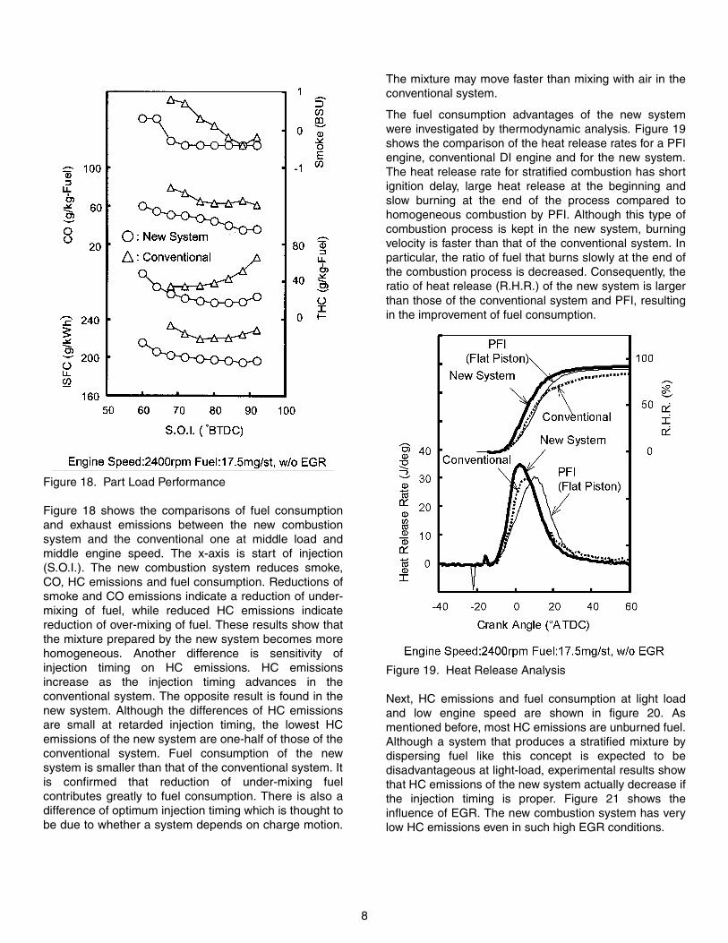
Figure 18. Part Load Performance
Figure 18 shows the comparisons of fuel consumptionand exhaust emissions between the new combustionsystem and the conventional one at middle load andmiddle engine speed. The x-axis is start of injection(S.O.I.). The new combustion system reduces smoke,CO, HC emissions and fuel consumption. Reductions ofsmoke and CO emissions indicate a reduction of under-mixing of fuel, while reduced HC emissions indicatereduction of over-mixing of fuel. These results show thatthe mixture prepared by the new system becomes morehomogeneous. Another difference is sensitivity ofinjection timing on HC emissions. HC emissionsincrease as the injection timing advances in theconventional system. The opposite result is found in thenew system. Although the differences of HC emissionsare small at retarded injection timing, the lowest HCemissions of the new system are one-half of those of theconventional system. Fuel consumption of the newsystem is smaller than that of the conventional system. Itis confirmed that reduction of under-mixing fuelcontributes greatly to fuel consumption. There is also adifference of optimum injection timing which is thought tobe due to whether a system depends on charge motion.
The mixture may move faster than mixing with air in theconventional system.
The fuel consumption advantages of the new systemwere investigated by thermodynamic analysis. Figure 19shows the comparison of the heat release rates for a PFIengine, conventional DI engine and for the new system.The heat release rate for stratified combustion has shortignition delay, large heat release at the beginning andslow burning at the end of the process compared tohomogeneous combustion by PFI. Although this type ofcombustion process is kept in the new system, burningvelocity is faster than that of the conventional system. Inparticular, the ratio of fuel that burns slowly at the end ofthe combustion process is decreased. Consequently, theratio of heat release (R.H.R.) of the new system is largerthan those of the conventional system and PFI, resultingin the improvement of fuel consumption.
Figure 19. Heat Release Analysis
Next, HC emissions and fuel consumption at light loadand low engine speed are shown in figure 20. Asmentioned before, most HC emissions are unburned fuel.Although a system that produces a stratified mixture bydispersing fuel like this concept is expected to bedisadvantageous at light-load, experimental results showthat HC emissions of the new system actually decrease ifthe injection timing is proper. Figure 21 shows theinfluence of EGR. The new combustion system has verylow HC emissions even in such high EGR conditions.

9
Figure 20. Part Load Performance
Figure 21. Emissions
CONCLUSIONS
A new combustion system that produces a stratifiedmixture by a fan-spray and shell-shaped piston cavity hasbeen developed. This system does not require specialcharge motion, such as tumble or swirl. The following arefeatures of this mixture preparation and the test engineresults.
1. Characteristics of the spray are:
• Large penetration compared to cone-spray
• Uniform fuel distribution in the spray
• The spray keeps its shape and uniformity of fueldistribution even if ambient pressure changes.
2. The eddy induced by the shear flow of the spray andcavity shape form an ellipsoidal stratified mixturewhile rolling up the originally thin and fan-shapedspray.
3. The new combustion system reduces under-mixingof fuel. LIF measurements and flame observationsconfirm this effect.
4. The new combustion system improves fuelconsumption as well as smoke, CO and HCemissions at middle load and middle engine speed.
5. Thermodynamic analysis shows that the newcombustion system makes the burning velocity fast,especially at the end of combustion process. Thiscauses increased heat release near TDC.
6. HC emissions at light load are lower than that ofconventional DI combustion systems, even in thecondition of high EGR.
ACKNOWLEDGEMENTS
The authors would like to thank all the collaborators atToyota Motor Corporation and Toyota Central R&D Labs.,Inc. for their supports and useful suggestions.
REFERENCES
1. J.Harada, T.Tomita, H.Mizuno, Z.Mashiki, Y.Ito,”Development of Direct Injection Gasoline Engine”,SAE 970540.
2. T.Kume, Y.Iwamoto, K.Iida, M.Murakami, K.Akishino,H.Ando, ”Combustion Control Technologies for DirectInjection SI Engine”, SAE 960600.
3. Y.Takagi, T.Itoh, S.Muranaka, A.Iiyama, Y.Iwakiri,T.Urushihara, K.Naitoh, ”Simultaneous Attainment ofLow Fuel Consumption, High Output Power and LowExhaust Emissions in Direct Injection SI Engines”,SAE 980149.
4. D.Andriesse, A.Ferrari, “Assessment ofStoichiometric GDI Engine Technology”, ConferenceEngine and Environment ’97,1997.
5. R.W.Anderson, J.Yang, D.D.Brehob, J.K.Vallance,R.M.Whiteaker, “Understanding Thermodynamics ofDirect Injection Spark Ignition (DISI) CombustionSystems: An Analytical and ExperimentalInvestigation”, SAE 962018.
6. M.Wirth, W.F.Piock, G.K.Fraidl, P.Schoeggl,E.Winklhofer, “Gasoline DI Engines: The CompleteSystem Approach by Interaction of AdvancedDevelopment Tools”, SAE 980492.
7. T.H.Lake, S.M.Sapsford, J.Stokes, N.S.Jackson,“Simulation and Development Experience of aStratified Charge Gasoline Direct Injection Engine”,SAE 962014.
8. J.E.witzky, S.Antonio, “Schichtladung undLuftverunreinigung bei Verbrennungsmotoren” MTZMotortechnische Zeitschrift 33, 1972.
9. M.grigo, M.Schwaderlapp, P.Wolters, “Charge-MotionControlled Combustion system for SI Engines withDirect Fuel Injection”, Fortschr Ber VDI Reihe 12,No.306, 1997.
10. G.Karl, J.Abthoff, M.Bargende, R.Kemmler, M.Kühn,G.Bubeck, “Thermodynamic Analysis of a StratifiedDirect Injected Gasoline Engine”, Fortschr Ber VDIReihe 12, No.267, 1996

10
11. R.Houston, G.Cathcart, “Combustion and EmissionsCharacteristics of Orbital’s Combustion ProcessApplied to Multi-Cylinder Automotive Direct Injected4-Stroke Engines”, SAE 980153.
12. Y.Wakuri, M.Fujii, T.Amitani, R.Tsuneya, “Studies onthe Penetration of Fuel Spray of Diesel Engine”(inJapanese), Bull. of JSME, Vol.3, No.9, p.123,1960.
13. Y.Iwamoto, K.Noma, O.Nakayama, T.Yamauchi,H.Ando, “Development of Gasoline Direct InjectionEngine”, SAE 970541.
14. K.Naitoh, Y.Takagi, “Synthesized Spheroid Particle(SSP) Method for Calculating Spray Phenomena inDirect-Injection SI Engines”, SAE 962017.
15. R.Ortmann, S.Arndt, C.Döring, S.Fehler, R.Grzeszik,“Atomization and Mixture Formation with High-Pressure Injectors for Gasoline Direct-InjectionEngines”.
16. K.Kawamura, A.Saito, Y.Tanasawa, “Measurement ofParticle distribution in Sprays by Laser-light-computed Tomography (part 2)”(in Japanese), JSAENo.36, 1987.
17. Y.Nomura, T.Fujikawa, M.Koike, M.Kanda,T.Kobayashi, “Prediction of Mixture Formation in theCylinder of DI Gasoline Engine”, Proceedings of The76th JSME Annual Meeting No.98-3, pp513-514,1998.
18. T.Fujikawa, Y.Hattori, K.Akihama, M.Koike,“Quantitative 2-D Fuel Distribution Measurements ina Direct-Injection Gasoline Engine Using Laser-Induced Fluorescence Technique”, Proceedings ofCOMODIA-98, pp.317-322, 1998.
19. M.Kanda, T.Baika, M.Koike, A.Saito, “Application of aNew Combustion Concept to Direct InjectionGasoline Engine”, SAE Annual Congress 2000,2000.