Embed Size (px)
DESCRIPTION
training program for Vacuum Circuit breaker VCB and VCUL&T
Citation preview

Electrical Systems & Equipment E&A IC

Electrical Systems & Equipment E&A IC
Project : Ruwais Refinery Expansion Project
TRAINING PROGRAM ONMEDIUM VOLTAGE SWITCHGEAR
EPC

Electrical Systems & Equipment E&A IC
Training Program – Medium Voltage Switchgear
Main Objective:
• Familiarize the participants with the Medium Voltageswitchgear supplied by L&T.
• Operation, Installation & Maintenance Instructions
• Do’s & Dont’s

Electrical Systems & Equipment E&A IC
Content- Day 1Training Program on Medium Voltage Switchgear
Sr.no.
Topic Description TrainingSchedule
1 Introduction to L&T L&T Corporate Film & Brief Overview to L&T EAIC
Day 1Session-1
2 Basic Description Terminologies and equipment used in Switchgear
3 Evolution of MVSwitchgear
Brief overview of Arc quenching techniquesEvolution of Vacuum as an Arc quenching medium.Working principle of Vacuum Interrupter
4 MV Switchgear -Standard,classification andspecification
Details on product specificationsProduct classification as per IEC standards
LUNCH- BREAK5 MV Switchgear –
Panel Construction &operation
Basic Switchgear StructureOperating Sequence / InstructionImportance of Interlocks from Safety / Operation point of view.All in built Interlocks of VCB and earth switch
Day 1Session-2
6 Vacuum CircuitBreaker
Vacuum Circuit Breaker detail overview- VCB Design- Operating Mechanism- Familiarity with the electrical devices- Shutter Mechanism- SDS

Electrical Systems & Equipment E&A IC
Content- Day 2Training Program- Medium Voltage Switchgear
Sr.no.
Topic Description TrainingSchedule
7 Vacuum Contactor Unit VCU designApplication of VCUOperating Mechanism (Opening & Closing)Familiarity with the electrical componentsShutter MechanismComparison between VCB and VCU
Day 2Session-3
8 Earthing Switch Importance of Earthing.Operating principle of Earthing switchInterlocks with earthing switch
9 Operating Instructions &Interlocks
Operating Sequence of VCB / VCUOperating Sequence of Earth SwitchGeneral Interlocks
LUNCH- BREAK10 Type Tests information Significance of the Type tests as per the IEC standards
IEC 62271-100, IEC 62271-200, IEC 62271-102
Day 2Session-4
11 Installation of spares Mounting & Removal of Closing, Tripping Coils & Spring Chargingmotor
12 Maintenance Schedule Importance of Maintenance as a Preventive measure / Elongation ofproduct life.What to do?When to do?How to do?

Electrical Systems & Equipment E&A IC
Content- Day 3Training Program- Medium Voltage Switchgear
Sr.no.
Topic Description TrainingSchedule
13 Electrical Components Selection of CT, VT, Surge Arrester, Voltage detecting Indication etcImportance of Above electrical Components
DAY 3Session-5
14 Understanding of ElectricalScheme
Emphasis on understandingWiring SchemeControl CircuitPower CircuitWiring scheme Interlocks
LUNCH- BREAK16 Do’s & Don'ts Good operation and maintenance practices.
Preventive & Corrective Measures to be followed in a Substation.Special DO’s & Dont’s for MV Switchgear
DAY 3Session-617 Q&A Open Forum for Discussion /Queries.

Electrical Systems & Equipment E&A IC
INTRODUCTION TO L&T
TRAINING PROGRAM ONMEDIUM VOLTAGE SWITCHGEAR
L&T Corporate Video

Electrical Systems & Equipment E&A IC
E&A IC : Business Units
Control & Automation Systems (C&A) Metering & Protection Systems (MPS)
Electrical Systems & Equipment (ESE)
• Market leaders in LVsystems in India
• MV SWITCHGEAR• Comprehensive
product range• Manufacturing
facility in 6 countries
• Market leader inSwitchgear in India
• Comprehensive productrange compatible to
International standards• ASTA certified products
• Leading SystemIntegration & Automation
Solution Provider• Solutions based on“Open Architecture”
• SCADA, Drives, Robotics& Process automation
systems
• Leading manufacturerof static energy meters.• Market leader in highend Trivector meters.
• In-house products forpre-paid metering and
AMR
Electrical Standard Products (ESP)

Electrical Systems & Equipment E&A IC
Saudi Arabia• LV Switchgear & MCCs• Integrated Automation
Systems
Mumbai• LV Switchgear & MCCs
• Integrated Automation Systems
Ahmednagar• MV & LV Switchgear
Mysore• Metering & Protection
Systems
Jebel Ali, UAE• Integrated Automation Systems
Australia• MV switchboards
• Swgr Systems
Indonesia• MV Switchgear
• Switchgear Systems
Malaysia• MV Switchboards
E&A IC : Manufacturing Locations
Coimbatore• LV Switchgear & MCCs

Electrical Systems & Equipment E&A IC
Plant Location - Ahmednagar

Electrical Systems & Equipment E&A IC
Plant Location - Ahmednagar
Manufacturing Facilities
In House Test Facilities
Certifications

Electrical Systems & Equipment E&A IC
Model : AE255 NTMake : AMADA , JapanCapacity : 20 T45 Tool StationPunching up to 4 mm MSAuto sheet loader facility
Model : HDS 8025 NTMake : AMADA, JapanCapacity : 80 TBending length up to 2.5 M
Manufacturing FacilitiesCNC TURRET PUNCH PRESS
CNC PRESS BRAKE

Electrical Systems & Equipment E&A IC
Model: TOGU IIIMake: AMADAUsed for Sharpening the Tools
AUTOMATIC TOOL GRINDER
CNC TURRET PUNCH PRESS
Model : EUROMAC 1250Make : EUROMACCapacity : 35 TUsed for Cu / AL bus barand link punching up to10 mm Thick CU
Manufacturing Facilities

Electrical Systems & Equipment E&A IC
BUS BAR POLISHING MACHINE MIG WELDING MACHINE
Manufacturing Facilities

Electrical Systems & Equipment E&A IC
SPOT WELDING MACHINE GRINDING AND BUFFINGSTATION
Manufacturing Facilities

Electrical Systems & Equipment E&A IC
9 tank process - Pretreatment facility
Fully Automated Powder coating line
Robotic painting applicator
PAINTING SET UP
Manufacturing Facilities

Electrical Systems & Equipment E&A IC
80KV POWERFREQUENCY TESTER IMPULSE TEST LAB
Testing Facilities

Electrical Systems & Equipment E&A IC
VCB TESTING TROLLEYSECONDARY INJECTIONTROLLEY
Testing Facilities

Electrical Systems & Equipment E&A IC
PANEL TESTING TROLLEY CONDUCTIVITY METER
Testing Facilities

Electrical Systems & Equipment E&A IC
Painting Thickness Meter
Push Pull MeterLug Pull Tester
Surface Plate & MeasuringInstrument
Testing Facilities

Electrical Systems & Equipment E&A IC
Various In-House Type Tests
• Partial Discharge• Lightning Impulse• Corrosion resistance• Temperature Rise• Primary Injection
PARTIAL DISCHARGETEMPERATURE RECORDER
Testing Facilities

Electrical Systems & Equipment E&A IC
Quality Systems
• ISO 9001 - 2008 - BV
• ISO 14001 - BV
• OHSAS 18001 - BV
Certifications

Electrical Systems & Equipment E&A IC
DESCRIPTION OF MV Equipment
TRAINING PROGRAM ONMEDIUM VOLTAGE SWITCHGEAR

Electrical Systems & Equipment E&A IC
Introduction to Switchgear
A switch is simply a means of opening orclosing the current path in an electriccircuit.
• There is no special opening conditionfor short circuit or other fault.
SWITCH
A fuse is used for over current and shortcircuit protection.
A fuse is a part of the circuit whichconsists of conductor which melts easilyand breaks the connection when electriccurrent exceeds the predetermined value.
• Fuse has to be replaced after everyFault.
FUSE
Electrical Systems & Equipment E&A IC
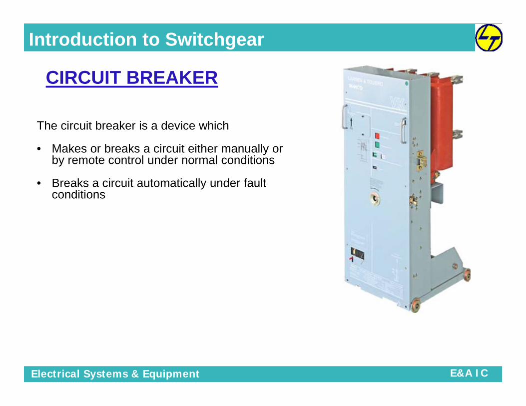
The circuit breaker is a device which
• Makes or breaks a circuit either manually orby remote control under normal conditions
• Breaks a circuit automatically under faultconditions
Introduction to Switchgear
CIRCUIT BREAKER

Electrical Systems & Equipment E&A IC
• Insulators - To insulate equipment from ground andother phases.
Busbar - To allow multiple connections from onefeeder to another feeder.
• Surge Arrester – Surge Arrester are the primaryprotection to make the circuit device immune todifferent types of over voltages and spikes eitheratmospheric or switching. Surge arrester are generallyconnected in parallel with the equipment to beprotected to divert the surge currents. A properlychosen and installed arrester is to be regarded aspractically maintenance free during its life time.
Introduction to Switchgear

Electrical Systems & Equipment E&A IC
• CT – Current Transformer are instrument transformer that are
used to supply a reduced value of current to meters, protective
relays and other instrument. CT’s provide isolation from the high
voltage primary , permit grounding of the secondary for safety
and step down the magnitude of the measured current to a
value that can be safely handled by instruments
• CBCT - The core-balance CT (or CBCT) is normally of the ring
type, through the centre of which cable is passed that forms the
primary winding. An earth fault relay, connected to the
secondary winding, is energized only when there is residual
current in the primary system
Introduction to Switchgear

Electrical Systems & Equipment E&A IC
• Voltage Transformers - Transformers which convert high
voltages into measurable and standardized voltages.
These are then proportional and in-phased to the primary
signal. They are intended to supply electrical measuring
instruments, meters, relays or other electrical devices.
Furthermore the connected measuring and protective
devices are electrically insulated against live parts.
• Voltage Detecting Unit – To detect voltage presence on
bus or cable side
• Capacitive Voltage Detector – To sense the voltage on
Busbar
Introduction to Switchgear

Electrical Systems & Equipment E&A IC
Brain = Relay
Eyes, Ears, Nose &Skin =
CTs, VTs
Hands & Legs=
Circuit Breakers
Protection System Analogy

Electrical Systems & Equipment E&A IC
Relay Issues TripCommand To
Breaker
Sensed byInstrument
Transformers &communicated to
Relay
Breaker Trips& Clears Fault
Protection System Analogy
FAULT

Electrical Systems & Equipment E&A IC
Introduction to MV SWITCHGEAR
TRAINING PROGRAM ONMEDIUM VOLTAGE SWITCHGEAR

Electrical Systems & Equipment E&A IC
It is the generic term including the entire range of switching devices and theircombination with associated control, measuring, protecting, and regulatingequipment.
• Carrying the normal load current
• Making or breaking the normal load current
• Clearing the fault current (for which sensing devices like CT, PTand various relays are employed) Assemblies containing electrical switching,protection, metering and management devices
• Used in three-phase, high-power industrial, commercial and utilityapplications
• Covers a variety of actual uses, including motor control, distribution panelsand outdoor switchyards
• The term "switchgear" is plural, even when referring to a single switchgearassembly (never say, "switchgears")
Introduction to Switchgear
SWITCHGEAR

Electrical Systems & Equipment E&A IC
Evolution of MV SWITCHGEAR
TRAINING PROGRAM ONMEDIUM VOLTAGE SWITCHGEAR

Electrical Systems & Equipment E&A IC
ARC Extinction Theory
When two current contacts just open, an arc bridges the contact gapthrough which the current gets a low resistive path to flow so there will notbe any sudden interruption of current.
The intensity of arc column depend up on the presence of ionized mediabetween separated electrical contacts, hence, special attention should begiven in reducing ionization or increasing deionization of media betweencontacts.
That is why the main designing feature of circuit breaker is to providedifferent pressure control methods, cooling methods for different arc mediain between circuit breaker contacts.

Electrical Systems & Equipment E&A IC
Oil is outdated in MV switchgear as insulating material because of firerisk and its susceptibility to contamination (moisture and by-productsafter switching). The maintenance requirements with its related costsalso plays a negative role in the application of oil.
BULK OIL CBOil is used as arc quenching media as well as insulating media between currentcarrying contacts and earthed parts of the breaker.
MINIMUM OIL CBA Minimum Oil circuit breaker places the interrupting unit in insulatingchamber at live potential. The insulating oil is available only in interruptingchamber.The features of designing MOCB is to reduce requirement of oil, andhence these breaker are called minimum oil circuit breaker.
OIL CIRCUIT BREAKER

Electrical Systems & Equipment E&A IC
AIR BLAST CB
Air can be considered outdated as arc-quenching medium, due to therelatively bulky volumes needed, sound aspects when operating andsensitivity for moisture.
Advantages Disadvantages
There is no chance of fire hazard causedby oil.
In order to have frequent operations, it isnecessary to have sufficiently highcapacity air compressor.
Arc quenching is much fasterduring operation of air blast circuit breaker.
Frequent maintenance of compressor,associated air pipes and automatic controlequipment is also
As the duration of arc is smaller , so lesseramount of heat realized from arc to currentcarrying contacts hence the service life ofthe contacts becomes longer.
Due to high speed current interruptionthere is always a chance of high rate ofrise of re-striking voltage and currentchopping.
Requires much less maintenancecompared to OIL Circuit Breaker
There also a chance of air pressureleakage from air pipes junctions.

Electrical Systems & Equipment E&A IC
The use of SF6 as an interrupting is not ecofriendly and advancedtechnology solutions like vacuum is available for upto 52KV. Howeverfor extra high voltages beyond this value it still remains the mostpractical solution.
Advantages Disadvantages
SF6 is a gas with good insulating properties,Have High dielectric strengthcolorless, odorless, non-toxic and non-flammable
SF6 is a potent greenhouse gas and should notbe released to the atmosphere.
SF6 molecule is electronegative, it providesexcellent insulation after extinction.
Density approximately five times that of air.
SF6 gives an excellent dissipation of heatwhich is cooling the arc and which is importantaround the zero crossing
Although pure SF6 is non-toxic, the by-products after arcing are extremely toxic formaintenance workers (in case of leakage).
Low force needed for contacts pressure SF6 arc byproducts (S -2 F-10) are hazardouswaste requiring special care for disposal.
Requires much less maintenance comparedto OIL & AIR Circuit Breaker
Special attention shall be given when theswitchgear has to be cleared at the end of itslife.
SF6 Circuit Breaker

Electrical Systems & Equipment E&A IC
Vacuum as an Arc quenching media have a number of attractive features like beingmaintenance-free, compact and environmentally friendly.
Other important features are:
• Large operation reliability: Because of its simple construction, the number ofcomponents is small (approximately 50 percent less than a comparable SF6 oroil circuit breaker).
• Small amount of operating energy. Due to the small stroke (≈8-12 mm) of thecontacts and the light weight of the accelerating mass, the required operatingforce is low. Consequently, the operating mechanism is of a very simple design.
• Low arcing voltage. Because of the low arcing voltage (≈30 V) the energy inthe arc is limited.
• Environmentally friendly: no danger of explosion and/or fi re, only little noisewhen operated.
• Excellent interrupting characteristics: arc duration below 10 ms
• Better Performance: Switching Life more than 3 times of that of a SF6 CB.
Vacuum Circuit Breaker
Vacuum Interrupter

Electrical Systems & Equipment E&A IC
MV SwitchgearStandard, Classification & Specification
TRAINING PROGRAM ONMEDIUM VOLTAGE SWITCHGEAR

Electrical Systems & Equipment E&A IC
IEC 62271-200:High-voltage switchgear and controlgear
AC metal-enclosed switchgear and controlgear for rated voltages above1 kV and up to and including 52 kV
IEC 62271-100:High-voltage switchgear and controlgear
Alternating-current circuit-breakers
IEC 62271-102:High-voltage switchgear and controlgear
Alternating Current Disconnectors and Earthing Switches
Compliance to IEC Standards

Electrical Systems & Equipment E&A IC
Product Classification
• Partition Metallic Class• (Metal Partitioned Compartment)• Partition Metallic Class• (Metal Partitioned Compartment)PMPM• Mechanical Endurance Class• (10,000 Mechanical Operations)• Mechanical Endurance Class• (10,000 Mechanical Operations)M2M2• Electrical Endurance Class• (Highest Breaking Capacity class for MV Switchgear)• Electrical Endurance Class• (Highest Breaking Capacity class for MV Switchgear)E2E2• Capacitive Switching Class• (Least chance of restriking during Capacitive Switching)• Capacitive Switching Class• (Least chance of restriking during Capacitive Switching)C2C2• Degree of Protection• (Ingress Protection against External agents)• Degree of Protection• (Ingress Protection against External agents)IP4XIP4X• Loss of Service Continuity Test• (Continuity access from one compartment to another)• Loss of Service Continuity Test• (Continuity access from one compartment to another)LSC-2BLSC-2B

Electrical Systems & Equipment E&A IC
Air insulated Switchgear
Vacuum Circuit BreakerPanel- VH1H12kV, 630A, 25kA
12kV, 1250A, 25kA
12kV, 2000A, 25kA
12kV, 2000A, 40kA
12kV, 3150A, 40kA
12kV, 3150A, 50kA
Vacuum Circuit BreakerPanel- VH1H12kV, 630A, 25kA
12kV, 1250A, 25kA
12kV, 2000A, 25kA
12kV, 2000A, 40kA
12kV, 3150A, 40kA
12kV, 3150A, 50kA
Vacuum ContactorUnit Panel2- Tier Design3.6kV, 400A, 50kA7.2kV, 400A, 40kA

Electrical Systems & Equipment E&A IC
AIS - 12 kV VCB Panel – up to 25kAType Designation VHIH
Voltage Upto 12 kV
Impulse withstand voltage 75 kVp
One minute power frequencywithstand voltage
28 kV rms
Frequency 50 Hz
Normal current Upto 1250 A
Short circuit breaking current25kA
63kAShort circuit making current
Duration of short circuit withstand 1 sec
Degree of Protection IP 41

Electrical Systems & Equipment E&A IC
AIS - 12 kV VCB Panel –31.5, 40 & 50kA
Type Designation VHIH
Voltage Upto 12 kV
Impulse withstand voltage 75 kVp
One minute powerfrequency withstandvoltage
28 kV rms
Frequency 50 Hz
Normal current Upto 3150 A
Short circuit breakingcurrent 31.5kA
80kA
40kA
100kA
50kA
125kAShort circuit makingcurrent
Duration of short circuitwithstand
1 sec
Degree of Protection IP 41
Electrical Systems & Equipment E&A IC
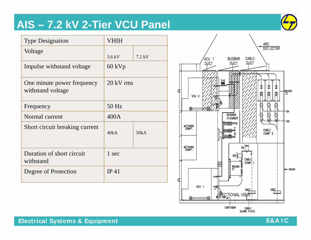
AIS – 7.2 kV 2-Tier VCU PanelType Designation VHIH
Voltage3.6 kV 7.2 kV
Impulse withstand voltage 60 kVp
One minute power frequencywithstand voltage
20 kV rms
Frequency 50 Hz
Normal current 400A
Short circuit breaking current40kA 50kA
Duration of short circuitwithstand
1 sec
Degree of Protection IP 41

Electrical Systems & Equipment E&A IC
Panel SpecificationParameters Rating / Description
System earthing Low Resistance Earthing
Insulation Level As per the System Voltage
Design Ambient 40 deg C
Auxiliary Supply-1 110 V DC
Auxiliary Supply-1 240 V AC
VCB Spring Charging Motor Supply 110V DC
Closing Coil Supply 110V DC
Trip Coil Supply 110V DC
Panel Space Heater Supply 240V AC, 50Hz
Plug & Socket Supply 240V AC, 50Hz
Panel Illumination Supply 240V AC, 50Hz
Power Cable Entry Rear Bottom
Auxiliary Control Supply Cable Front ( for 25kA Panels)Rear (for 31.5kA, 40kA & 50 kA Panels)

Electrical Systems & Equipment E&A IC
Scope of Supply
Board Details VCU400A
630A(25kA)
1250A(25kA)
2000A(25kA)
2000A(40kA)
3150A(40kA)
4000A(50kA)
SRNO
BOARDNO
NO. OFPANELS
QTY
1 MYB0230 31 20 3
2 MYB0231 12 7 3
3 MYB0232 33 25
4 MYB0233 37 49 3 3
5 MYB0234 45 . 34
6 MYB0235 4 2
7 MYB0236 22 15
8 MYB0237 17 14 3
9 MYB0238 16 11
10 MYB0239 19 13
TOTAL 236 70 3 2 3 84 6 37

Electrical Systems & Equipment E&A IC
MV Switchgear – Panel Construction
TRAINING PROGRAM ONMEDIUM VOLTAGE SWITCHGEAR

Electrical Systems & Equipment E&A IC
Type VHIH switchgear is completely metal-clad (LSC2B) and compartmentalized.
The switchgear is fully assembled, wired-up and tested in the factory beforedelivery.
The VHIH panel is fabricated from high grade pickled and oiled steel sheets,which is chemically treated before painting to provide adequate protectionagainst corrosion and weathering.
The cubicle parts are Powder coated process which provides optimum protectionagainst corrosion and weathering.
The paintwork is tested to withstand 1000 hours in a 5% salt spray.
Panel Construction

Electrical Systems & Equipment E&A IC
Panel Construction
The Panel consists of fourcompartments
• Circuit breaker compartment
• Busbar compartment
• Cable & CT compartment
• Low voltage compartment

Electrical Systems & Equipment E&A IC
Circuit breaker Compartment
The circuit breaker compartment contains a withdrawablevacuum circuit breaker which moves on two in-built rails.
It can be transferred between the Connected and Testpositions of circuit breaker compartment using a RackingHandle with the door closed.
In the Connected /service position, the moving upper andthe lower contact arms of the VCB engages with the fixedcontacts connected to the busbars and the outgoingcircuit respectively.
Shutters operated by the VCB movement in the Test/Disconnected positions, separates the contact arms andtheir fixed contacts.
These shutters prevent access to the fixed contacts,while in isolated position.

Electrical Systems & Equipment E&A IC
Cable Compartment
• No live parts are located less than 300 mmabove floor level.
• The cable termination height is well above floor• level, and generous space is provided for• terminating power cables.
• This ensures a higher bending radius as well• as reduces tension on the terminals.
• The cable chamber also houses the CT and the earthing Switch and main earthbusbar.
• The Gland Plate is fitted at rear bottom of cable compartment. The cable isaccessible from rear of the cubicle by opening the cable compartment covers.
• All CT, CBCT, fixed type VT, Surge Arrestors , Earth Switch are mounted here.
• Anti-condensation Space Heater along with the thermostat to keep moisture away.
• Pressure relief flaps are provided at top.
• Earthbar running throughout the switchboard

Electrical Systems & Equipment E&A IC
Busbar Compartment
Busbar Bushing / Fixed contacts isconnected to breaker.
The busbar extends from one Compartmentto the adjacent.
All the busbar joints are covered with PVCBoots.
Main busbar extensible at both ends
Main Busbars Boot

Electrical Systems & Equipment E&A IC
Low Voltage Compartment
The low voltage compartment contains theequipment viz.
• Fuses / MCBs• Control terminals• Protective relays• Indicating lamps• Meters• Push buttons• Control switches• Illumination Lamp
These equipment operating on Auxiliary Supplyvoltage are mounted on LV compartment door andinside LV Compartment

Electrical Systems & Equipment E&A IC
Arc Deflector / Gas Duct
Pressure relief flaps are provided at the top portion of the panel to ensuresafety to the operator in the event of an internal arc fault
The Arc Deflectors / Gas Duct at the top will ensure that the ionized gases aresafely evacuated

Electrical Systems & Equipment E&A IC
Shutter Mechanism
Shutter Operation
• Metallic Shutters covers the Fixed contactsin the VCB compartment.
• Opening / Closing of Shutters is actuatedwith the movement of the VCB.
• Shutters for Fixed contacts on Busbar andCable side can be padlocked individuallyduring maintenance.
• Metallic Shutters are earthed.

Electrical Systems & Equipment E&A IC
Shutter Mechanism- BusbarShutter Operation - Busbar
• Figure-1 shows the stud which actuatesthe movement of the Shutter Assembly(figure-2) in the VCB Compartment onLHS.
• Figure-3 shows the Busbar shutteropened.
Figure-1
Figure-2 Figure-3
Electrical Systems & Equipment E&A IC
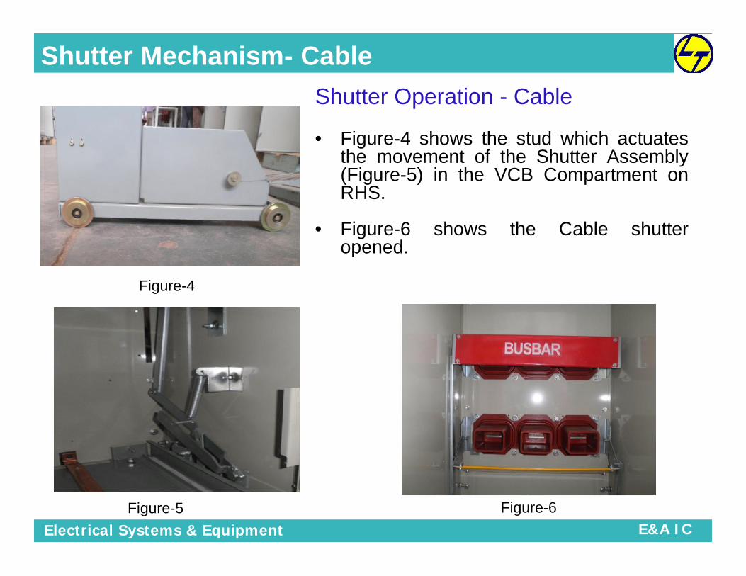
Shutter Mechanism- CableShutter Operation - Cable
• Figure-4 shows the stud which actuatesthe movement of the Shutter Assembly(Figure-5) in the VCB Compartment onRHS.
• Figure-6 shows the Cable shutteropened.
Figure-4
Figure-5 Figure-6

Electrical Systems & Equipment E&A IC
Control Circuit Plug Arrangement
A removable plug at the panel connects these controlwires to the fixed wiring at the metering compartment.Ensure that the plug makes full connection beforefastening the clasp as shown below figure
The breaker can only be racked intothe CONNECTED position when thesecondary control plug is inserted.
Control circuit plug can be insertedby moving the Red leverDownwards.
Control Plug
Control PlugArrangementon VCB

Electrical Systems & Equipment E&A IC
VACUUM CIRCUIT BREAKER
TRAINING PROGRAM ONMEDIUM VOLTAGE SWITCHGEAR

Electrical Systems & Equipment E&A IC
Vacuum Circuit Breaker- DesignHorizontal Isolation
The mating of the contacts of the VCB is inhorizontal direction
Horizontal Draw-out out Type
The VCB Truck can be drawn out of the panelhorizontally.
Truck Mounted Design
The VCB mechanism is mounted on the truck(trolley).

Electrical Systems & Equipment E&A IC
VACUUM CIRCUIT BREAKER- Front

Electrical Systems & Equipment E&A IC
VACUUM CIRCUIT BREAKER- Rear

Electrical Systems & Equipment E&A IC
VACUUM CIRCUIT BREAKER- Mechanism
AuxiliarySwitch
ClosingSpring
Closing SpringCharging Motor
TrippingSpring
OperationCounter
Trip Coil
ClosingCoil

Electrical Systems & Equipment E&A IC
VCB Manual Operation
Note - Confirm that the circuit breaker is in the “OPEN” state indicated as bythe OFF position at the ON / OFF indicator.
a) Charging Operation
Manual charging can be performed in the event that the motor malfunctions.
The CHARGED/DISCHARGED indicator will change its color from white(DISCHARGED) to yellow(CHARGED), indicating that the closing spring isfully charged.
Push the CLOSE button to initiate the close operation. The indicators on thebreaker will now read CLOSED and DISCHARGED.
Push the TRIP button to initiate the opening operation. The indicator will nowread OPEN.

Electrical Systems & Equipment E&A IC
VCB Electrical Operation
When the power supply is connected to theoperation circuit, energy from the motor isstored in the closing spring.
When the spring charging is complete, thelimit switches opens and the motor stops.
The indicator shows CHARGED condition,confirming that the spring charging iscomplete.
As the closing spring may be released by aclosing signal, the limit switch closes whenthe closing operation terminates, causingthe motor to run.
A) Charging Operation Spring

Electrical Systems & Equipment E&A IC
B) Closing Operation
When the closing coil is excited by a closingsignal, the closing catch is released and theclosing cam is rotated by the closing spring,which in turn rotates the main shaft.
The main shaft drives the vacuum interruptersthrough the wipe spring, and the circuit breakercloses.
CAUTION: DO NOT repeat the closingoperation once the breaker is closed.
C) Tripping Operation
When the tripping coil is excited by a tripping signal, the trippingcatch is released, and the breaker is opened by the openingspring.
VCB Electrical Operation

Electrical Systems & Equipment E&A IC
A) Excellent Breaking Performance
B) High Reliability
C) Safety for personnel and operating safety
D) Minimized Maintenance
E) Compact & Light
VCB Features
VCB Safety Interlocks• VCB cannot be engaged or withdrawn unless it is in open
condition
• VCB can only be closed or opened if it is in engaged orisolated position (and in between)
• Interlocking with earth switch
• Interlocking with cubicle door

Electrical Systems & Equipment E&A IC
VCU Design and Application
VacuumContactor Unit

Electrical Systems & Equipment E&A IC
VCU Construction
VacuumContactor Unit
HT FuseJaw
Contacts
VacuumInterrupter
Cradle
Shutter

Electrical Systems & Equipment E&A IC
Application of VCU
Main application in motor switching duty like Pumping stations
Cranes, Forward Reverse operations in mines, Lift Hoists
Transformer Switching
Neutral grounding of Generators, Operations of soft starters
Switching of Reactor Capacitor switching for reactive powercompensation

Electrical Systems & Equipment E&A IC
A) Excellent Breaking Performance
B) No Surge Protection Required
C) Safety for personnel and operating safety
D) Minimized Maintenance
E) Compact & Light
F) Low Power consumption
G) Conformity to Insdustrial Standard
VCU Features

Electrical Systems & Equipment E&A IC
Difference between VCB & VCU
VacuumContactor Unit
Vacuum CircuitBreaker

Electrical Systems & Equipment E&A IC
Difference between VCB & VCU
CHARACTERISTIC CIRCUIT BREAKER CONTACTOR with FUSES
Continous Currents High (1200A, 2000A. 3000A, 4000A)Moderate (400A enclosed- NEMA size H3, or 720Aenclosed size H6)
Switching Capability
Switching current from very low(magnetising) values to full systemshort-circuit current
# Switching current from very low (magnetising)values to interrupting capability of vacuum contactorwithout fuses ( at least 10 x continous rating)
# Fuses operate for currents higher than theinterrupting capability capability of vacuumcontactor alone, up to the interrupting capcity of thefuse
Endurance-Mechanical
High (typically 10,000 operations) ( referto ANSI/IEEE C37.06) & IEC 62271 Very high, 10,00,000 to 25,00,000 operations
Endurance-Electrical High Very high.
# for Vacuum, typically 10,000operations at rated continous current
#Switching continuous current, 400,000 operationsfor 400A & 200,000 operations for 720A
# for Vacuum, typically 30 to 100operations at full short-circuit rating
Switching short-circuit current, endurence data notestablished in NEMA or UL standards; short-circuitcurrent interruption requires replacement of current-limiting fuses
Applicationlimitations
Not appropriate for very high endurenceapplications Well suited for very frequent switching operatioons
OperationsElectrically operated (manual operationfor maintance or emergency) Electrically operated only

Electrical Systems & Equipment E&A IC
CHARACTERISTIC CIRCUIT BREAKER CONTACTOR with FUSES
Control Scheme Mechanically latched- circuit breaker remainsclosed on loss of system voltage
# Usually magnetically held-vacuum contactoropens on loss of system voltage; vacuumcontactor will close automatically on systemvoltage return with two-wire control, manualrestart required on system voltage return withthree-wire control
# Latched contactors are also available
Overcurrent/ short-circuit protection Requires protective relays
Requires protective relays for overloadprotection and current limiting fuses for short-circuit protection
short-circuit let-through energy
High (three to five cycles or more of short-circuitcurrent)
Low (current-limiting fuses interrupt in 1/4 cyclefor highest short-circuit currents, and peakmagnitute is limited)
Remote operation Well suited Well suited
Control power Control power needed for protective relays, circuitbreaker operation and space heaters ( if present)
Control power usually provided by controlpower transformer (CPT) incorporated in thecontroller
Construction # Drawout, if metal-clad (ANSI/IEEE c37.20.2) #Stationary, if metal-enclosed (ANSI/IEEE C37.20.3) Drawout or Stationary
Space requirement # Large enclosure# NEC required workspace equal
# Smaller enclosure# NEC required workspace equal# Rear access not required
Purchase cost Relativally high Moderate
MaintenanceMedium (long maintenance intervals, need toclean insulation)
Low (simple mechanism, need to cleaninsulation, replace fuses)
Difference between VCB & VCU
Electrical Systems & Equipment E&A IC
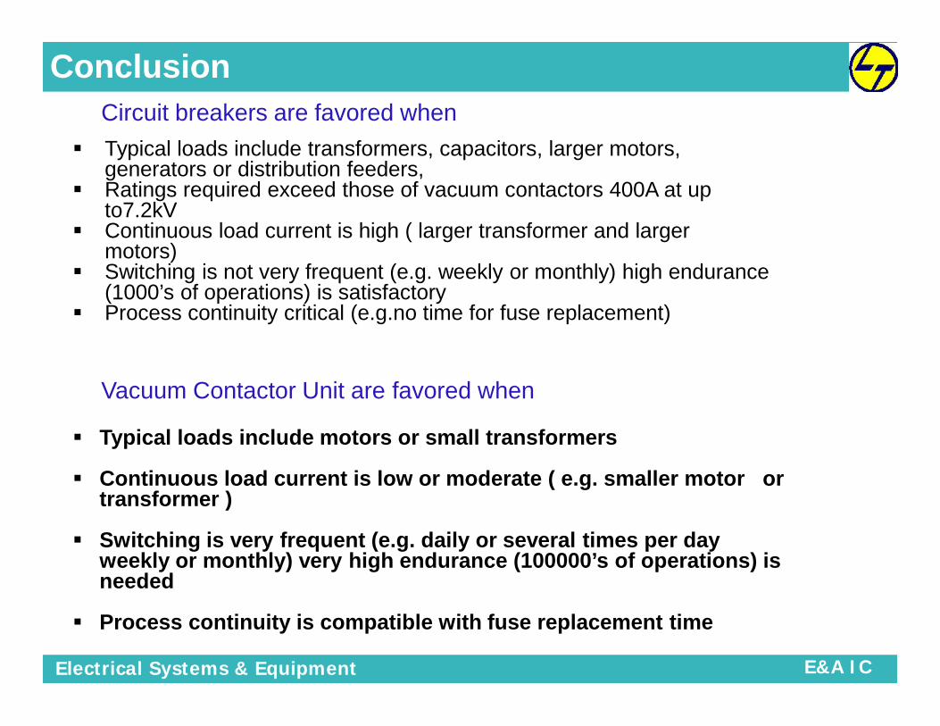
Conclusion
Typical loads include transformers, capacitors, larger motors,generators or distribution feeders,
Ratings required exceed those of vacuum contactors 400A at upto7.2kV
Continuous load current is high ( larger transformer and largermotors)
Switching is not very frequent (e.g. weekly or monthly) high endurance(1000’s of operations) is satisfactory
Process continuity critical (e.g.no time for fuse replacement)
Circuit breakers are favored when
Vacuum Contactor Unit are favored when
Typical loads include motors or small transformers
Continuous load current is low or moderate ( e.g. smaller motor ortransformer )
Switching is very frequent (e.g. daily or several times per dayweekly or monthly) very high endurance (100000’s of operations) isneeded
Process continuity is compatible with fuse replacement time

Electrical Systems & Equipment E&A IC
Earthing Switch
TRAINING PROGRAM ONMEDIUM VOLTAGE SWITCHGEAR

Electrical Systems & Equipment E&A IC
Earthing Switch
Window forVCB racking
Handle
Window forEarthingSwitch
Operation
Rotate Earth switch Handle as perInstruction given . Do Not Rotatein Reverse Direction. It MayDamage the interlocks.

Electrical Systems & Equipment E&A IC
Earthing Switch
Earth SwitchOperation –
OFF Position
Earth SwitchOperation –ON Position
Earth SwitchHandle
Insert ESWHandle till Red
Mark

Electrical Systems & Equipment E&A IC
Earthing Switch & Interlocks
Basic Interlocks which are commonly provided in a MV switchboard. VCB can not be racked in or connected to service position from test
position when;a. VCB in closed position b. Without control Plug.c. Earth switch in closed position. d. Door is opened.
While VCB in service position;a. Earth switch can not be closed b. Control plug can not be removed.c. Closed VCB can not be racked out. d. VCB door can not be opened.
While VCB in intermediate position;a. VCB can not be closed b. Control plug can not be removed.
While VCB in Test position;a. VCB door can be opened b. ESW can be operated.c. Control plug can be removed and inserted.
VCB only can be opened and closed while in test and service position.
These are equipped with a snap action spring device which ensures anindependent closing speed. They can make and withstand short-circuitcurrents

Electrical Systems & Equipment E&A IC
Operating Sequence/ Instructions
TRAINING PROGRAM ONMEDIUM VOLTAGE SWITCHGEAR

Electrical Systems & Equipment E&A IC
VCB Rack-In Operation – Closed Door
1. ENSURE THE FOLLOWING BEFORERACK-IN;
a VCB IS IN ‘TEST’ POSITIONb CONTROL PLUG IS PROPERLYCONNECTED TO VCB.
c VCB IS IN ‘OPEN’ CONDITION.d. EARTH SWITCH IS OFF
1. ENSURE THE FOLLOWING BEFORERACK-IN;
a VCB IS IN ‘TEST’ POSITIONb CONTROL PLUG IS PROPERLYCONNECTED TO VCB.
c VCB IS IN ‘OPEN’ CONDITION.d. EARTH SWITCH IS OFF
2. CLOSE THE DOOR ANDTIGHTEN THE CAPTIVESCREW.
2. CLOSE THE DOOR ANDTIGHTEN THE CAPTIVESCREW.
3. LIFT THE ‘LEVER A’, OPENTHE FLAP OF ‘SOCKET FORVCB RACKING HANDLE’, ANDINSERT THE VCB RACKINGHANDLE,
3. LIFT THE ‘LEVER A’, OPENTHE FLAP OF ‘SOCKET FORVCB RACKING HANDLE’, ANDINSERT THE VCB RACKINGHANDLE,
5. ROTATE THE RACKINGHANDLE CLOCKWISE UNTIL;
a VCB POSITION INDICATORSHOWS ;SERVICE’ ANDb MECHANICAL RESISTANCE ISFELT TO ROTATE HANDLE
5. ROTATE THE RACKINGHANDLE CLOCKWISE UNTIL;
a VCB POSITION INDICATORSHOWS ;SERVICE’ ANDb MECHANICAL RESISTANCE ISFELT TO ROTATE HANDLE
6. REMOVETHE RACKING
HANDLE.
6. REMOVETHE RACKING
HANDLE.

Electrical Systems & Equipment E&A IC
VCB Rack- Out Operation – Closed Door
1. ENSURE THE FOLLOWING BEFORE RACK-OUT;
a VCB IS IN ‘OPEN’ CONDITION.b VCB POSITION INDICATOR SHOWS‘SERVICE’ POSITION.
1. ENSURE THE FOLLOWING BEFORE RACK-OUT;
a VCB IS IN ‘OPEN’ CONDITION.b VCB POSITION INDICATOR SHOWS‘SERVICE’ POSITION.
2. LIFT THE ‘ LEVER A’. OPEN THEFLAP OF SOCKET FOR VCBRACKING HANDLE AND INSERT THEVCB RACKING HANDLE
2. LIFT THE ‘ LEVER A’. OPEN THEFLAP OF SOCKET FOR VCBRACKING HANDLE AND INSERT THEVCB RACKING HANDLE
3. ROTATE THE RACKING HANDLE ANTICLOCKWISEUNTIL
(a) THE HANDLE STARTS ROTATING FREELY AND
(b) VCB POSITION INDICATOR SHOWS ‘TEST’
3. ROTATE THE RACKING HANDLE ANTICLOCKWISEUNTIL
(a) THE HANDLE STARTS ROTATING FREELY AND
(b) VCB POSITION INDICATOR SHOWS ‘TEST’
4. REMOVE THERACKING HANDLE.
4. REMOVE THERACKING HANDLE.

Electrical Systems & Equipment E&A IC
VCU Rack-In Operation – Closed Door
1. ENSURE THE FOLLOWING BEFORERACK-IN;
a VCU POSITION INDICATIONS SHOWS‘DCON’b CONTROL PLUG IS PROPERLYCONNECTED TO VCU.
c VCU IS IN ‘OPEN’ CONDITION.d. EARTH SWITCH IS OFF
1. ENSURE THE FOLLOWING BEFORERACK-IN;
a VCU POSITION INDICATIONS SHOWS‘DCON’b CONTROL PLUG IS PROPERLYCONNECTED TO VCU.
c VCU IS IN ‘OPEN’ CONDITION.d. EARTH SWITCH IS OFF
2. CLOSE THE DOOR ANDTIGHTEN THE CAPTIVESCREW.
2. CLOSE THE DOOR ANDTIGHTEN THE CAPTIVESCREW.
3. OPEN THE VCU OPERATINGWINDOWAND INSERT THEVCU RACKING HANDLE
3. OPEN THE VCU OPERATINGWINDOWAND INSERT THEVCU RACKING HANDLE
4. PULL THE VCU HANDLE UP TODRIVE THE VCU TO CONNECTEDAND EARTH OFF POSITION
5. CHECK THE VCU POSITIONINDICATOR FOR ‘CON’ POSITION
4. PULL THE VCU HANDLE UP TODRIVE THE VCU TO CONNECTEDAND EARTH OFF POSITION
5. CHECK THE VCU POSITIONINDICATOR FOR ‘CON’ POSITION
6. REMOVETHE RACKINGHANDLE AND
CLOSE THEVCU
OPERATINGWINDOW.
6. REMOVETHE RACKINGHANDLE AND
CLOSE THEVCU
OPERATINGWINDOW.

Electrical Systems & Equipment E&A IC
VCU Rack- Out Operation – Closed Door
1. ENSURE THE FOLLOWING BEFORE RACK-OUT;
a VCU POSITION INDICATION SHOWS ‘CON’b VCU IS IN OPEN CONDITION
1. ENSURE THE FOLLOWING BEFORE RACK-OUT;
a VCU POSITION INDICATION SHOWS ‘CON’b VCU IS IN OPEN CONDITION
2. OPEN THE VCU OPERATINGWINDOW AND INSERT THE VCURACKING HANDLE
2. OPEN THE VCU OPERATINGWINDOW AND INSERT THE VCURACKING HANDLE
3. PUSH THE HANDLE DOWN TO BRING THE VCU TODISCONNECTED POSITION AND EARTH SWITH ONPOSITION.
4. CHECK THE VCU POSITION INDICATOR FOR‘DCON’ INDICATION
3. PUSH THE HANDLE DOWN TO BRING THE VCU TODISCONNECTED POSITION AND EARTH SWITH ONPOSITION.
4. CHECK THE VCU POSITION INDICATOR FOR‘DCON’ INDICATION
4. REMOVE THERACKING HANDLE ANDCLOSE THE VCUOPERATING WINDOW.
4. REMOVE THERACKING HANDLE ANDCLOSE THE VCUOPERATING WINDOW.

Electrical Systems & Equipment E&A IC
Earth Switch Operation
1. ENSURE THAT VCB IS AT‘DISCONNECTED’ & ‘TEST’ POSITION.1. ENSURE THAT VCB IS AT‘DISCONNECTED’ & ‘TEST’ POSITION.
2. MOVE THE ‘LEVER B’ TO LEFT TOOPEN THE COVER OF EARTH SWITCHOPERATING MECHANISM.
2. MOVE THE ‘LEVER B’ TO LEFT TOOPEN THE COVER OF EARTH SWITCHOPERATING MECHANISM.
3. INSERT THE EARTHSWITCH OPERATINGHANDLE.’
3. INSERT THE EARTHSWITCH OPERATINGHANDLE.’
4. PULL THEHANDLE UPWARDTO ‘SWITCH ON.
4. PULL THEHANDLE UPWARDTO ‘SWITCH ON.
5. REMOVE THERACKING HANDLE.5. REMOVE THERACKING HANDLE.

Electrical Systems & Equipment E&A IC
GeneralInterlocks
TRAINING PROGRAM ONMEDIUM VOLTAGE SWITCHGEAR

Electrical Systems & Equipment E&A IC
General Interlocks
SDS Interlock (Control Plug)VCB cannot be Racked in unless the Control plug is fitted.Ensure that SDS is Plugged in during VCB / VCU during Rack In.
SDS Interlock (Control Plug)VCB cannot be Racked in unless the Control plug is fitted.Ensure that SDS is Plugged in during VCB / VCU during Rack In.
VCB Positive InterlockVCB cannot be engaged or withdrawn unless it is in OPEN positionVCB Positive InterlockVCB cannot be engaged or withdrawn unless it is in OPEN position
VCB Negative InterlockVCB cannot be operated unless it is in Service or Test position. IeVCB cannot be closed when in intermediate position.
VCB Negative InterlockVCB cannot be operated unless it is in Service or Test position. IeVCB cannot be closed when in intermediate position.
Closed Door OperationsAll operations are behind closed door.In any case VCB/VCU should not be operated in open doorcondition
Closed Door OperationsAll operations are behind closed door.In any case VCB/VCU should not be operated in open doorcondition
Earth Switch InterlockVCB cannot be engaged when Earthing Switch is CLOSEDEarthing switch cannot be closed when VCB is engaged
Earth Switch InterlockVCB cannot be engaged when Earthing Switch is CLOSEDEarthing switch cannot be closed when VCB is engaged

Electrical Systems & Equipment E&A IC
General InterlocksOTHER INTERLOCKS
1. Racking in & racking out of VCB & VCU is not possible unless it is OFF
2. VCB/VCU can be closed only when it is in service or test position
3. VCB/VCU cannot be operated while it is in intermediate position
4. VCB/VCU cannot be racked in or operated unless control plug is inserted
5. VCB/VCU can be withdrawn only when control plug is removed
6. It shall not be possible to remove control plug while the VCB/VCU is inIntermediate or service position
7. Control Plug can be removed only when VCB/VCU is in Test DisconnectedPosition
8. VCB/VCU can be operated / moved from Disconnected position/ test position onlywhen Earth Switch is in OPEN condition
9. Earth Switch can be operated only when VCB/VCU is in test/disconnected position
10. Earth Switch cannot be operated if VCB/VCU is in service / intermediate position.Access to Earth switch Operating Handle is Blocked.
Electrical Systems & Equipment E&A IC
General Interlocks
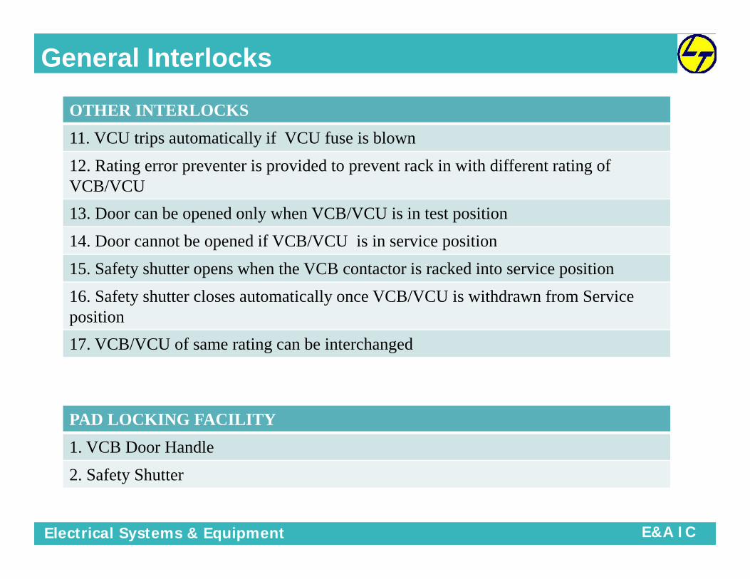
OTHER INTERLOCKS
11. VCU trips automatically if VCU fuse is blown
12. Rating error preventer is provided to prevent rack in with different rating ofVCB/VCU
13. Door can be opened only when VCB/VCU is in test position
14. Door cannot be opened if VCB/VCU is in service position
15. Safety shutter opens when the VCB contactor is racked into service position
16. Safety shutter closes automatically once VCB/VCU is withdrawn from Serviceposition
17. VCB/VCU of same rating can be interchanged
PAD LOCKING FACILITY
1. VCB Door Handle
2. Safety Shutter

Electrical Systems & Equipment E&A IC
Type Test Details
TRAINING PROGRAM ONMEDIUM VOLTAGE SWITCHGEAR

Electrical Systems & Equipment E&A IC
Type tests
Short Time Current Withstand & Peak WithstandShort Time Current Withstand & Peak Withstand
Lightning Impulse Voltage WithstandLightning Impulse Voltage Withstand
HV Power Frequency Dry Withstand TestHV Power Frequency Dry Withstand Test
Temperature Rise Test & Measurement of ResistanceTemperature Rise Test & Measurement of Resistance
Degree of Protection TestDegree of Protection Test
Internal Arc Fault Withstand TestInternal Arc Fault Withstand Test
Mechanical Operation & Integrity of Interlocks TestMechanical Operation & Integrity of Interlocks Test
Basic Test DutyBasic Test Duty

Electrical Systems & Equipment E&A IC
Type testsShort Time Current Withstand & Peak Withstand
1. STC = Fault current duration in kA for 1 Sec / 3 Sec (rms)
2. Peak Current = 2.5 times (rms) for 50 Hz Application
3. Peak Current = 2.6times (rms) for 60Hz Application
4. Followed by supplementary test of contact resistance measurement & dry powerHV Withstand capacity test
HV Power Frequency Dry Withstand Voltage (PFWV)
1. Short Duration (1 minute) test voltage 2 to 4 times the rated maximum Voltage
Eg – For rated max. voltage 12 kV = 28kV rms (as per IEC standard)
Lightning Impulse Withstand Voltage (LIWV or BIL)
1. A fast rising voltage impulse 4 to 12 times rated Maximum voltage
2. Rise time = 1.2 microseconds and decay to 50% in 50 microseconds
Eg – for rated max voltage 12kV = 75kV peak (as per IEC standard)

Electrical Systems & Equipment E&A IC
Type testsMechanical Operation
Switching devices and withdrawable parts shall be operated 50 times,
Removable parts inserted 25 times and removed 25 times to verify satisfactoryoperation of the equipment
Ingress Protection - IP
Extent of protection provided by an enclosure, partition or shutter if applicable, againstaccess to hazardous parts, against ingress of solid foreign objects and/or ingress ofwater and verified by standardized test methodsEg – IP 4X for Indoor Sub station Panels
Basic Test Duty
1. Short circuit switching duties verified for different fault currents as under for breakeroperating sequence ( O - 0.3sec - CO – 3 min – CO )2. Switching Current (kA) = T10, T30, T60, T100s & T100a
3. Followed by supplementary test of contact resistance measurement & dry power HVWithstand capacity test

Electrical Systems & Equipment E&A IC
Type tests – Internal Arc Test - Classification
Classification: IAC ( “Internal Arc Classified” )
Accessibility: A (F, L, R)*B (F, L, R)*C
Test values: Current [ kA ] and duration [ s ]
Example 1: IAC A FLR 40 kA 1 s
Example 2: IAC B FL 31.5 kA 0.5 s
• F = Front; L = Lateral; R = Rear
• A= Autorised operators; B = GeneralPublic; C= Pole mounted /unreachable
Electrical Systems & Equipment E&A IC
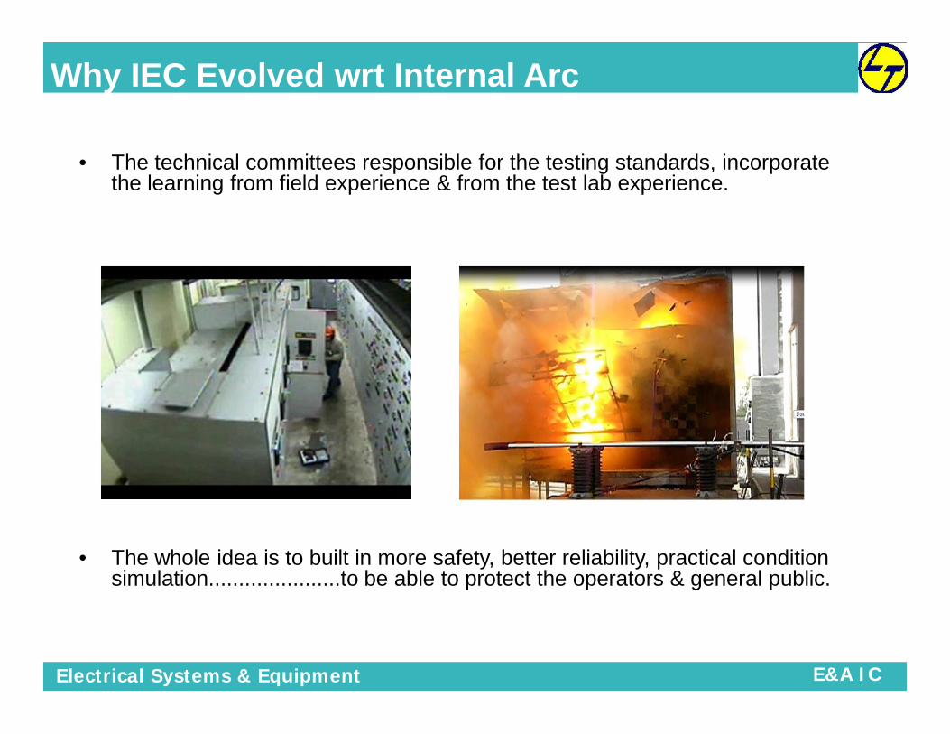
• The technical committees responsible for the testing standards, incorporatethe learning from field experience & from the test lab experience.
• The whole idea is to built in more safety, better reliability, practical conditionsimulation......................to be able to protect the operators & general public.
Why IEC Evolved wrt Internal Arc

Electrical Systems & Equipment E&A IC
Overcoming Weaknesses of old IECOvercoming Weaknesses of old IEC
1: Old IEC allowed middle cubicle of the switch board for internal arc testing.•Consequence - The middle cubicle was supported from the 2 sides & was not testedfor the worst condition.
•Remedy - The new IEC makes it mandatory to perform the internal arc test on theextreme cubicle.
1: Old IEC allowed middle cubicle of the switch board for internal arc testing.•Consequence - The middle cubicle was supported from the 2 sides & was not testedfor the worst condition.
•Remedy - The new IEC makes it mandatory to perform the internal arc test on theextreme cubicle.
2: Old IEC did not demand simulation of room condition•Consequence - The hot gases, released from the test object, went up in the skywhereas in real condition these shall hit the roof & get reflected from the roof & maycause fatality.
•Remedy - The new IEC makes it mandatory to simulate side walls & roof like a room &then only test the switchgear.
3: Old IEC did not demand close door operation•Consequence - The MV switchgear could be operated with the door open therebyexposing the operator directly to the possible arc products & rendering the IAC testmeaningless.
•Remedy - The new IEC makes it mandatory to test the switchgear in “real operatingcondition”. Implying that if the door has to be opened for operation then the switchgearbe tested with door open condition. Indirectly making “all operation behind closed doora mandatory feature.
Internal Arc Fault

Electrical Systems & Equipment E&A IC
Type tests – Internal Arc TestInternal Arc Test in following compartments:
• CB Compartment
• Busbar Compartment
• Cable Compartment
Criteria 1 – Doors & Covers must not open
Criteria 2 – Parts of the Switchgear must not fly-off
Criteria 3 – Holes must not develop on the external parts ofthe enclosure
Criteria 4 – Indicators must not ignite
Criteria 5 – Earth connections must remain effective
Test Passing Criteria
Electrical Systems & Equipment E&A IC
Installation of Spares
TRAINING PROGRAM ONMEDIUM VOLTAGE SWITCHGEAR

Electrical Systems & Equipment E&A IC
Installation of Spares
Mounting Trip Coil
Removal of Trip coil
Mounting Spring Charging Motor
Removal of Spring Charging Motor
Removal of Closing coil

Electrical Systems & Equipment E&A IC
Maintenance Schedule
TRAINING PROGRAM ONMEDIUM VOLTAGE SWITCHGEAR

Electrical Systems & Equipment E&A IC
MAINTENANCE AND INSPECTION SCHEDULEWhy Maintenance ?
Preventive maintenance today, Can avoid costly failures tomorrow
The failures that can lead to….
Major breakdowns A loss of production A loss of property Even a loss of lives
Ultimately a loss to the Business

Electrical Systems & Equipment E&A IC
MAINTENANCE AND INSPECTION SCHEDULE
The frequency of the maintenance depends essentially onservice conditions viz.. Frequency of operation
Tripping on fault
Relative humidity
Presence of dust & reactive gases
After every 3000 mechanicaloperations OR
After six months if switchboard isexposed to dust OR
After an idle period longer than sixmonths ORevery year
It is Recommendedto carry outPreventive
Maintenance
When maintenance is required ?

Electrical Systems & Equipment E&A IC
Upkeep of switchboard room
Switchboard room should be clean, well
ventilated & dust free.
Ensure switchboard room to be free from
insects, rats & lizards
Closed loop air supply & exhaust system to be
ensured in dusty surrounding
Cable trenches, bus duct entries are to be
sealed to restrict the entry of lizards, rats &
snakes
Upkeep of switchboard room

Electrical Systems & Equipment E&A IC
Pressurized air circulation system to be used in a contaminatedenvironment where chemical gases, fumes, steam fumesetc,which can cause harmful effects to the switchboardequipment
Appropriate measures to be taken to avoid leakage & seepageof water through ceiling & walls inside the switchboard room asit can lead to flashovers
A thermometer should be installed in the vicinity of theswitchboard for monitoring ambient temperature
Entry to the switchboard room should be restricted toauthorized personnel only, preferably to have locking provision.
Upkeep of switchboard room
Upkeep of switchboard room

Electrical Systems & Equipment E&A IC
Name and telephone numbers of the nearest dispensary anddoctor should be displayed
Fire fighting equipment and Fire alarms as prescribed by thesafety department should be available in working condition.
Relevant drawings of switchboard e.g. General arrangementdrawing, Wiring diagram, should be kept inside the cupboardfor reference whenever required
A hydraulic or manual operated trolley should be keptavailable for loading & unloading of the Vacuum CircuitBreakers.
Upkeep of switchboard room

Electrical Systems & Equipment E&A IC
MAINTENANCE AND INSPECTION SCHEDULE
Before starting the maintenance
Switch off incoming power supply before starting maintenance. Lock out
incoming power supply. For safe operations, rack out incomer VCBs to
isolated position & lock them
Measure voltage on busbars to ensure that busbars are de-energized.
Switch off the control supply.
Isolate remote control voltage sources.
Ensure that only qualified personnel are instructed
and permitted to use the defeat mechanism
to gain access to an energized panel

Electrical Systems & Equipment E&A IC
MAINTENANCE AND INSPECTION SCHEDULE
Do not attempt to withdraw the unit or disconnect any terminations when
the defeat mechanism has been used to open a compartment door.
Current transformer primaries must not be energized when secondary's
are open circuited.
Only manufacturer recommended lubricants should be used.
For safety of personnel working on busbars, provide temporary earthing
using a metallic chain/strip near the workplace. Remove this earthing
only after the job is completed.
Before starting the maintenance

Electrical Systems & Equipment E&A IC
MAINTENANCE AND INSPECTION SCHEDULE
After maintenance, if Panel is going to be de-energised for a longer
period, switch on the panel space heaters to prevent moisture
condensation on the cables/insulators.
vacuum cleaners should be used to remove dust and avoid moisture
condensation in the switchboard
Use recommend tools and equipment for maintenance of switchboards
Before starting the maintenance

Electrical Systems & Equipment E&A IC
MAINTENANCE AND INSPECTION SCHEDULE
Recommended Tools for maintenance Cleaning
Dry cloth
CRC 2-26 Spray
Vacuum cleaner with small nozzle
WD - 40 ( Rust Preventer )
Zero Grade Emery Paper ( not for contacts )
Tightening
Screw drivers 6”, 8”, 10”
Double ended spanners ( 4mm to 19mm )
Socket spanner set ( upto 19mm )

Electrical Systems & Equipment E&A IC
MAINTENANCE AND INSPECTION SCHEDULE
Torque wrench 0.3 to 1.2 kg.m, 1.2 to 7 kg.m, 5.0 to 23.0 kg.m
Heavy duty Star Screw Driver (12 “)
Allen key set 0 - 10mm
Plier 8”
Tubular spanners
Nose pliers 8”
Wire stripper 0 - 6 sq.mm
Small star screw driver
Recommended Tools for maintenance

Electrical Systems & Equipment E&A IC
MAINTENANCE AND INSPECTION SCHEDULE
General Guidelines for switchboard maintenance
All electrical power should be de-energised, tagged and locked out
accordingly with established procedures.
Access covers and enclosures should be removed and all assemblies
should be hand cleaned with a dry lint free cloth and non metallic brushes.
Do not use cotton waste for cleaning.
Special attention should be given to insulating surfaces.
High power vacuums should be used to remove all loose debris.
Compressed air should be avoided to prevent forcing dust and
contaminates into other components.

Electrical Systems & Equipment E&A IC
MAINTENANCE AND INSPECTION SCHEDULE
Contacts in circuit breakers, contactors, and other switching equipment like
Earthing switches should be inspected & cleaned of all dirt.
All the components of switchboard should be examined for cracks, defective
plating, frayed wires, burnt insulation, and general overall condition
Ensure tightness of Cable, connections and components, also mechanical parts
of equipments should be free to function
Loose connections and damaged insulations should be repaired or replaced to
avoid Over heating and flashover
General Guidelines for switchboard maintenance

Electrical Systems & Equipment E&A IC
Busbar connections and fasteners to be ensured for tightness
Frame grounding cable for tight connections
Insulating materials / creep surfaces, clean, intact / retape taped bars asneeded
Fuses and earthbar links, right size and tight
Switches, knobs, present and all in good condition
Ensure VCB ON-OFF operation at least 4 to 5 times, also free operation ofother mechanical parts
Lubricate appropriate components, do not over lubricate
What to Inspect…?
MAINTENANCE AND INSPECTION SCHEDULE

Electrical Systems & Equipment E&A IC
Cables and bundles secured, no abrasive contacts
Charging handles and rails, in position and secured
Insulation matting, always in place
Equipment labeling is correct
Structural integrity of enclosures, Gas duct and IAF flaps are in place
Latches and locks operating
What to Inspect…?
MAINTENANCE AND INSPECTION SCHEDULE

Electrical Systems & Equipment E&A IC
(a) Cleaning• All dust and dirt found on the top covers should be brushed off and cleaned prior to
commencing any dismantling to minimize ingress of dirt into internal portions of theswitchgear panel. Use lint-free clean cloth to clean the switchgears.
(b)Insulation• All insulation surfaces should be cleaned and closely inspected for signs of tracking,
treeing, blistering, and delamination or mechanical damage. There should be no trace ofgrease on any part of the insulation surfaces especially at the spouts in the breakercompartment. Clean and dry insulators with a suitable cleaning agent.
• Caution: Cleaning agent cannot be used on the black & grey surfaces of the• bushing or on the copper bars.
(c) Heater• The operation of all heaters, where fitted, should be verified.
What to Inspect…?
MAINTENANCE AND INSPECTION SCHEDULE

Electrical Systems & Equipment E&A IC
(d) Main and Earth busbars connections• Ensure that all connections are tight and that good contact is maintained.• This examination should include opening the boots for torque checks on the
busbar bolt joints. There is a very slim chance for yearly shutdown of the bus, butchecks should be done at least once in three years.
(e) Secondary wiring and fuses• Ensure that the connections are tight and good contact is maintained. Verify the
continuity of wiring to the fuses, instrument transformers, relays, instruments andother associated devices.
• All contacts including that for the plug and socket contacts should be cleaned andlubricated sparingly with the correct lubricant. Fuses should be tested forcontinuity and inspected for signs of deterioration.
•
What to Inspect…?
MAINTENANCE AND INSPECTION SCHEDULE

Electrical Systems & Equipment E&A IC
(f) Auxiliary switches, indicating devices and interlocks• Auxiliary switches should be kept in a clean and operational condition because
they are critical to the correct functioning of the equipment, especially theprotection system.
• Indicating devices such as semaphores should be tested for good operations• and blown bulbs replaced. Interlocks and locking devices should receive
particular attention, especially those associated with earthing and testingfacilities. A strained or worn out
• device may result in a dangerous condition. It should be verified that any mal-operation is satisfactorily inhibited. Lubricate when necessary.
(g) Shutters• The shutter mechanisms should be verified for correct operation and lubricated
sparingly. This should normally be carried out immediately after the withdrawal ofthe breaker from its housing or immediately prior to reenergization.
What to Inspect…?
MAINTENANCE AND INSPECTION SCHEDULE

Electrical Systems & Equipment E&A IC
What to Inspect…?
MAINTENANCE AND INSPECTION SCHEDULE
(h) Isolating contacts• The isolating contacts should be examined for discoloration and
deformation due to overheating or environmental contamination. Replace ifnecessary. Replace conductors if cause is overheating. For environmentalcontamination, eliminate source of contamination and clean the platingsurface with appropriate cleaning agent.
(i) Earthing switches• Earthing switches should be examined for correct operation and its contacts
for good connections. The correct interlocking between the earthing switchand the breaker should be verified.

Electrical Systems & Equipment E&A IC
MAINTENANCE AND INSPECTION SCHEDULE
(j) Meters, Transducers and Batteries• For the following items, refer to the relevant manufacturer's instruction
manuals provided for operation checks:• Protection relays• Voltmeters and ammeters• Energy meters (active or reactive)• Transducers (voltage, current, watt, var)• DC tripping/control supply
(k) Protection relays• Wipe off any dust on the relay covers before removing them. Ensure that
the covers are securely replaced to minimize the ingress of dust into therelays. Injection testing by primary injection is preferred. However, regulartesting by secondary injection is sufficient to prove the integrity of the relays.
• Tests should be made on protection relays to verify the operating andresetting times, the pick-up and drop-off values.
What to Inspect…?

Electrical Systems & Equipment E&A IC
MAINTENANCE AND INSPECTION SCHEDULE
• In the case of electro-mechanical relays, great care should be taken toavoid damage to the relay mechanisms when manipulating the inductiondisc of the relay.
• In general, avoid subjecting protection relays to high-voltage tests. If suchtests are required, ensure that the correct test voltages are applied to avoiddamage to the relay, especially the solid state type.
• If it is necessary to disturb any connections for testing purposes, ensure thatthese connections are correctly restored before returning the switchgearsinto service.
(l) Current transformers (CT) and voltage transformers (VT)• Steps should be taken to ensure that voltage transformers are isolated and
discharged to earth before commencing examination. Care should be takento ensure that the transformers are not made live inadvertently due tofeedback from the secondary windings.
• In the case of the CT, attention is drawn to the dangerous voltages that mayresult if the secondary's are open-circuited while the primaries are on load.
What to Inspect…?

Electrical Systems & Equipment E&A IC
MAINTENANCE AND INSPECTION SCHEDULE
• Any connections removed for checking/testing must be correctly replacedand securely tightened. Insulation resistance and continuity tests of thesecondary windings should be carried out where possible.
• Generally, check CT's and VT's for physical appearance and that all relatedconnections are tight. The insulation material should be cleaned and closelyexamined for any signs of damage such as cracks, tracking marks orpeeling.
• In case of withdrawable VT's, the isolating contacts should be checked,cleaned and lubricated sparingly. The correct operation of safety shutters forthe VT truck should also be verified. Primary and secondary fuses shouldbe tested for continuity.
(m) Control relays or contactors• Inspect mechanical parts for free movement with the control and main
circuits isolated. Check the operation of the relays/contactors by energisingthe control circuit.
What to Inspect…?

Electrical Systems & Equipment E&A IC
Maintenance of Switchboard
BUSBAR ZONE
Check that power cables do not exert undue pressure on the termination
Ensure proper clamping of cables on the glands and cable clamps to avoidweight of cables acting directly on the termination
Close rear door covers/plates
Check whether joint shrouds are in it’s place
Remove rear door plates and check for tightness (at the specified torque values)of hardware for busbar / fishplate coupling. Poor connections will causeoverheating.
MAINTENANCE AND INSPECTION SCHEDULE
POWER CABLE ZONE

Electrical Systems & Equipment E&A IC
Check for unused holes, block them
Check for presence of shrouds/boots on outgoing terminals
Check for proper termination of extension links
Always use copper wires / cables for control purposes
Check all power and control circuit connections at terminal blocks, cable
terminals, switch terminals, contactor terminals, for tightness
Refer to the scheme diagrams and terminal chart before reconnecting the
meters and relays
Maintenance of SwitchboardMAINTENANCE AND INSPECTION SCHEDULE

Electrical Systems & Equipment E&A IC
Inspect all devices to ensure that the equipment is in proper working order
Check that all CT secondary shorting links are present
Ensure that the wires are not hanging loose. Temporary connections madeduring testing should be removed
Check the setting of Intelligent relays as per setting chart
Check the setting of overload relays and other protection relays
Check that fuses are fitted in main and auxiliary circuit and that ratings areappropriate for the circuit
Maintenance of Switchboard
MAINTENANCE AND INSPECTION SCHEDULE

Electrical Systems & Equipment E&A IC
Inspect all wiring for wear and cuts, wherever they pass on sharp edges
Look for wear of the silver plating on the contacts & on the earthing contacts fixed to VCBand at the point where they engage with the fixed contacts.
Clean & lubricate the contacts once a year with HP MPL (EXXON) grease
Look for indications of overheating, arcing or insulation breakdown Inspect power andcontrol contacts. Replace worn out contacts
Inspect all auxiliary and control circuits for desired functioning
Grease racking screw and telescopic rails at least once a year ( HP - LETHON - 2 orSYNTHOLUBE-20 of HJ Leach & Co.)
Inspect all door gaskets for wear and replace where necessary
Maintenance of Switchboard
MAINTENANCE AND INSPECTION SCHEDULE

Electrical Systems & Equipment E&A IC
Before energizing the switchboard Inspect busbar chamber, unit compartments and cable alleys, remove tools, conductor
strands and any other material lying loose
Use vacuum cleaner to remove dust, small particles etc.
Check tightness of electrical joints
Remove CT secondary shorting while connecting the meters or relays
Close all doors before energizing the board, do not operate any equipment with it’s
compartment door open when the board is energized
Ensure correct settings of protection relays for overload and short circuit coordination
MAINTENANCE AND INSPECTION SCHEDULE

Electrical Systems & Equipment E&A IC
Check for operation of the feeders as per scheme drawing
Equipment must be operated at rated voltages. Check the supply voltage before the circuit
is energized
Remove all temporary wires
Remake all connections removed for troubleshooting purposes
Check for the quality of the work after it’s completion
Ensure proper earthing connections
Be alert of undesirable grounds and eliminate them
Measure the insulation resistance with 2000 volts megger between phases and between
phase and ground. It should be more than 500 Mega-ohm
Before energizing the switchboard
MAINTENANCE AND INSPECTION SCHEDULE

Electrical Systems & Equipment E&A IC
Repeated HV test deteriorates the insulation properties. Avoid repeated HV
test
Ensure that all other VCBs and switches are OFF while making the Incomer
ON
Switch ON the space heaters beforeenergizing of Switchboard
Before energizing the switchboard
MAINTENANCE AND INSPECTION SCHEDULE
Space Heater
Effect of High humidity & Water sipage inSwitchgear

Electrical Systems & Equipment E&A IC
MAINTENANCE AND INSPECTION SCHEDULE
CHECKPOINT CHECK ITEM CHECK METHOD CRITERIA WHAT TO DO FREQUE
NCY
Entire VCB
Tightness of boltsand nuts
By tightening themwith screw driverand wrench
No loose connectionsRe-tighten looseconnections
Once in3
years*
Dust and foreignmatter
Visual checkThe VCB should beclear of dust andstains
Clean with a vacuumcleaner. Wipe with aclean, dry cloth andrecommended cleaningagent (AS66)
Deformation,excessive wearand damage
Visual checkNo deformation,excessive wear ordamage
Replace parts, ifnecessary
Lost or missingparts
Visual check No missing parts Replace missing parts
Controlcircuit
Electrical closingand tripping
Check at the“DISCONNECTED”position
The closing andtripping operationscan be done smoothlyMotor can springcharge automatically
Check circuits and theclosing and trippingdevices.When the motor cannotspring charge, check ifline fuse is blown.Replace if blown.
Once in3
years*

Electrical Systems & Equipment E&A IC
MAINTENANCE AND INSPECTION SCHEDULE
Operatingmechanism
Dust and foreignmatter
Visual checkThere should be nodust and foreignmatter
Remove foreignmatter withpressurized air
Once in 3years*
Smooth operation Manual operationOperation should besmooth
Clean off oldlubricant and apply asmall amount offresh lubricant, ifnecessary.
Lubricant ofbearing pins
Check by sightand touch
Shaft of closingand trippingportion
Visual check Must rotate smoothly
Main circuitdisconnects/contact finger
Dis-colouration ofcontacts
Visual checkThere should be a thinfilm of contact greaseon the contact surface
Clean the contactsurface of old greaseand apply a thin filmof new grease
Once in 3years*
Main barrierContaminationand dis-colouration
Visual check
There should be noforeign matter
Clean with pressuredair and then wipewith clean cloth Once in 3
years*There should be notracking marks, cracksor damages
Replace whendamaged
CHECK POINT CHECK ITEM CHECK METHOD CRITERIA WHAT TO DO FREQUENCY

Electrical Systems & Equipment E&A IC
MAINTENANCE AND INSPECTION SCHEDULE
Measurementof insulationresistance
When the insulationresistance betweenthe main circuitterminals is low,clean the surface ofthe vacuuminterrupter with a drycloth and then takethe measurementsagain
Once in 3years*
Main conductor-Ground / Mainconductors
500MΩ or more 2000V
Control circuit Ground 2 MΩ or more 500V
Measurementof contactresistance
Measuring location Resistance TesterCheck wipe andcontact gaps
Once in 3years*Across each set
contacts1250A <75µΩ
Micro-O-meter
Timing Test Across each set ofcontacts
Trip test & Close test As per specs
Carried outwhen speedof operationis critical
CHECK POINT CHECK ITEM CHECK METHOD CRITERIA WHAT TO DO FREQUENCY

Electrical Systems & Equipment E&A IC
Troubleshooting
Part Trouble Possible Cause Remedy
DO
OR
Handle cannot belocked
Wrong key (if any)
Internal mechanism rusted
Internal mechanism faulty
1. Check key number
2. Lubricate hole
3. If in emergency, cut off thehandle
Loose handleFixing screws loose
Internal mechanism worn out
1. Re-tighten the screws
2. Replace handle
STR
UC
TUR
E
Door warped and loose
Loose screws at the hinges
Hinge pin bent
Door deformed by external force
Re-adjust the door and tighten thescrews
Rectify the hinge pin
Repair the deformed portion
Internal noise
Partition plates vibrating due toelectromagnetic Induction/loose screwson partition plates
Cable touching gland plate.
Partial discharge due to stained or moistinsulating material
For screwed on partition plates,retighten the screws.
For gland plates, add sealingcompound between cable andplate
Shutdown power and clean thesurface of the insulatingmaterial. Switch on the heatersto dry the air inside the cubicle

Electrical Systems & Equipment E&A IC
TroubleshootingM
AIN
CO
ND
UC
TOR
S Connections overheated1. Loose bolts
2. Overload
Re-tighten bolts to specified torqueor replace busbar if necessary
Limit current to the rated value
Ground fault or faileddielectric tests
Insulators cracked
Insulators stained with foreign matters andmoisture
Intrusion of rodents
1. Replace insulators
2. Clean and dry insulators withsuitable cleaning agent
3. Plug gaps and openings andremove rodents
ControlCircuit
Extinction of indicatingtights
Bulb filament broken
Fuse or resistor burnt
Poor contact of auxiliary switches at thebreaker
Auxiliary supply switches open circulated
Limit switch contact shifted or faulty
Replace bulb
Replace fuse or resistor
Clean the auxiliary contacts
Check MCCB of fuse and wireterminals
Check limit switches contact andoperation of limit switch.
Simultaneous lighting ofboth ON and OFFindicating lights
Poor contact of breaker auxiliary switches
Contact resistance increased due to dustcontamination or oxidation of contacts(especially when they are not operated forprolonged period)
Clean contacts of auxiliary switch
Operate the auxiliary switch severaltimes
Poor operation of controlcircuits
Loose screws on the terminal blocks
Control circuit plug not properly connected
1. Re-tighten screws on theterminal blocks
2. Re-insert the control circuit plug
Part Trouble Possible Cause Remedy

Electrical Systems & Equipment E&A IC
TroubleshootingVA
CU
UM
CIR
CU
IT B
REA
KER
VCB cannot close
Circuit breaker not fully inserted
REMOTE/LOCAL selector switch incorrectlyselected
Auxiliary supply MCCB open
Control circuit plug not connected
Control circuit voltage drop
Closing coil burnt
1. Breaker to be aligned withthe CONNECTED positionsticker
2. Switch to correct position
3. Close the MCCB
4. Connect the control plug
5. Restore the voltage
6. Replace the coil
VCB cannot open
1. REMOTE/LOCAL selector switchincorrectly selected
2. Auxiliary supply MCB/switch open
3. Control circuit voltage drop
Switch to correct position
Close the MCB/Switch
Restore the voltage
VCB cannot be inserted intocubicle
Wrong rating of breaker
Lock lever does not lift up due to theCLOSED position of breaker
Insert the breaker of the correctrating
Trip the breaker
Adjust the shutter mechanism,lubricate the moving part
SHU
TTER
Shutters cannot close1. Shutter damaged
2. Moving parts poorly adjustment andlubricating oil deteriorated
Repair damaged shutters
Adjust moving parts and applylubricating oil
Clean the moving part
Part Trouble Possible Cause Remedy
Electrical Systems & Equipment E&A IC
Electrical Components
TRAINING PROGRAM ONMEDIUM VOLTAGE SWITCHGEAR

Electrical Systems & Equipment E&A IC
Understanding of Electrical Scheme
TRAINING PROGRAM ONMEDIUM VOLTAGE SWITCHGEAR

Electrical Systems & Equipment E&A IC
TRAINING PROGRAM ONMEDIUM VOLTAGE SWITCHGEAR

Electrical Systems & Equipment E&A IC
DO’s
DO’s
All operation behind Close Door.
Ensure following before racking VCB from TEST toSERVICE position1. VCB is in TEST Position2. VCB is in OPEN condition3. Earth Switch is in OFF condition4. Control Circuit plug is fully engaged. Red lever on control
plug mechanism should come upward direction whenControl Plug is fully engaged
Earth Switch shall be operated when VCB is inDISCONNECTED position.Earth switch handle shall be rotated in direction shown only.

Electrical Systems & Equipment E&A IC
DO’s
DO’s
Cross check rating of VCB before insertion inside the panel
Complete switchboard shall be free from Dust & other foreignparticles
All opening including hole provided for earthing connectionare properly closed with seal to avoid vermin/reptile entry
Ensure VCB Compartment door is fully closed and all Allenbolts on VCB compartment door is fully tightened. Then DoorPadlock shall be done.

Electrical Systems & Equipment E&A IC
DONT’s
DON’Ts
Do not apply any flammable lubrication on busbar jointsor VCB finger contacts
Do not perform any operation in OPEN door condition
Do not try to rack in VCB when control plug is notengaged. By operating the VCB forcefully it may damagethe control plug mechanism
Do not try to rack in VCB when VCB is in CLOSEDcondition
Do not try to operate Earth Switch when VCB is inCONNECTED position

Electrical Systems & Equipment E&A IC
DONT’s
DON’Ts
Do not try to insert wrong rating VCB inside the panel
Do not insert VCB without unlatching the shutterassemblies
Do not try to by pass VCB compartment door interlockwhen the feeder is in live condition
Do Not operate the padlock handles if door bolts are nottightened fully by Allen key.
All Interlocks are designed as per IEC working withcertain Torque Limits. Do not exert force higher than 750Newton as per IEC.
Do Not try to rotate ESW in the wrong direction

Electrical Systems & Equipment E&A IC
Q & A
Electrical Systems & Equipment E&A IC
Thank you


![ASIA OSS Training Program [Training the Trainers ]](https://img.pdfslide.tips/doc/110x75/547ce50cb47959ac508b4795/asia-oss-training-program-training-the-trainers-.jpg)