Embed Size (px)
Citation preview

Transformers Change voltage, frequency remains

Principle of Function
dtdN
dtdue i
Φ⋅=
Ψ==−
Maxwell-Faraday law of induction

Single-Phase Transformer Magnetic circuit
u1 ui10
i10
Φ1h0
ui20 u20
N1
N2
Input (primary) winding
Output (secondary) winding

u1 ui1
ui2 u2 i1
i2
L1σ
L2σ
11
11111
1111 iudtdiLiR
dtd
NdtdiLiRu ++⋅=
Φ++⋅= σ
µσ
22
22222
2222 iudtdiLiR
dtd
NdtdiLiRu +−⋅−=
Φ+−⋅−= σ
µσ
hh 21 Φ+Φ=Φµ
Fundamental Transformer Equation

X2σ
X1σ h
Real Transformer with Sinusoidal Supply
111111ˆˆˆˆ
iUIXjIRU +⋅⋅+⋅= σ 222222ˆˆˆˆ
iUIXjIRU +⋅⋅−⋅−= σ
1U 1ˆ
iU
2ˆ
iU 2U
2I
1I

Electromotive Force Ui in Winding Φh = Φhm . sin ωt
ui = N . dΦ /dt = N .Φhm . ω. cos ωt
ω = 2πf
2mUU = for sinusoidal waveform
12
1max11 ⋅⋅⋅Φ⋅= ωµNUi Ui1 = 4,44· f1·N1· Φμmax
Watch out!
Ui … effective value
Φμmax … maximum value
44,42
2=
πUi2 = 4,44· f1·N2· Φμmax
2
1
2
1
i
i
UU
NNp ==

Equivalent Circuit of Transformer

Φ1h
Φ1σ
No-Load Operation
µσ
IXU
XXRUI
hh
=≅++
=1
102
1121
1010
)(
10110110 ˆˆˆ iUjXIRU ++⋅= σ
1020 ˆˆ iUU =′
)%105(10 −≈i

Current Waveform in No-Load Operation

Iron Losses ΔPFe ΔPFe = f ( Bhm , f ) Losses in equivalent circuit are represented
by appropriately placed resistor. Equivalent resistance RFe is connected with main reactance X1h in parallel.
010 FePP ∆≈
FeIII 1110 ˆˆˆ += µ

201 ˆˆˆ III ′+=
Complete Equivalent Circuit of Transformer

Complete Equivalent Circuit of Transformer
hFe
hFejXRjXRZ
1
10ˆ
+⋅
=
σ111ˆ jXRZ +=
σ222ˆ XjRZ ′+′=′
00111 ˆˆˆˆˆ IZIZU ⋅+⋅=
00222 ˆˆˆˆˆ IZIZU ⋅+′⋅′−=′

Phasor Diagram of Transformer with Load

Short-circuit operation
1k
I1k = I1N
1k
)13,004,0(1 −≈ku
Short circuit voltage in per unit system:
kN
k
N
Nk
N
kk z
ZZ
UIZ
UUu 1
1
1
1
11
1
11 ==
⋅==
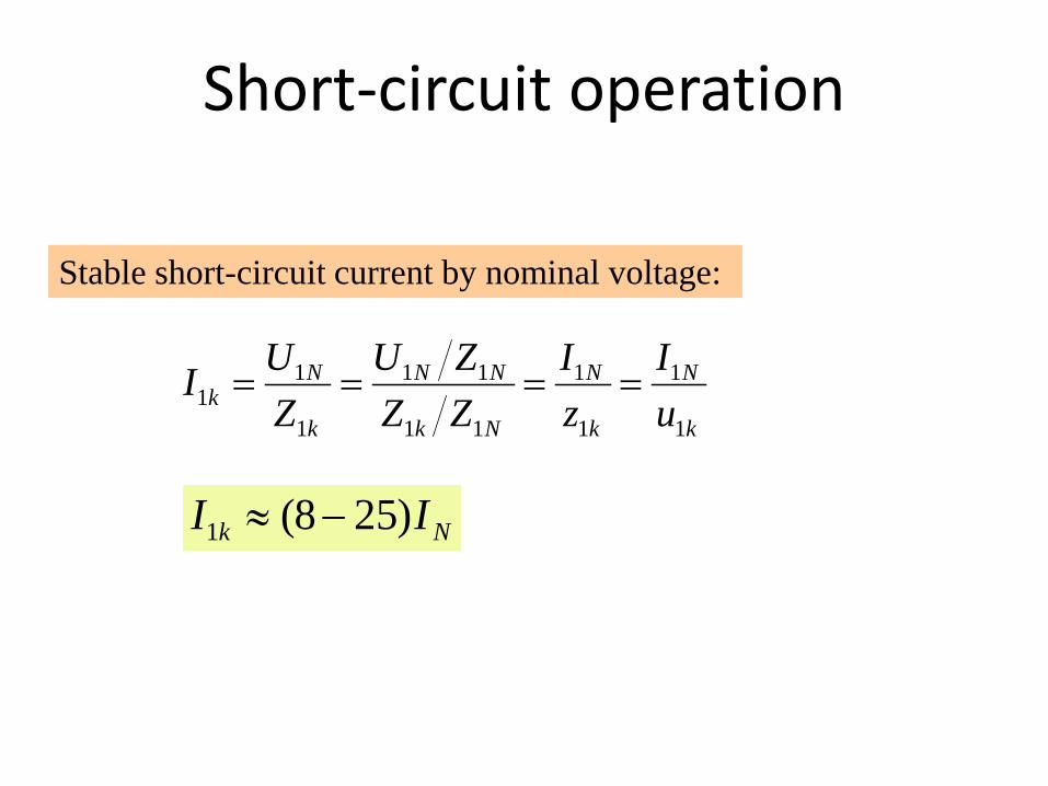
Stable short-circuit current by nominal voltage:
k
N
k
N
Nk
NN
k
Nk u
IzI
ZZZU
ZUI
1
1
1
1
11
11
1
11 ====
Nk II )258(1 −≈
Short-circuit operation

1k
I1k = I1N
1k R1k = R1 + R′2
X1k = X1σ + X′2σ
Z1k = R1k + jX1k
k
kkk ZR 111 cosϕ=
kkk ZX 111 sinϕ=Per unit no-load losses ΔpkN :
kNN
kN
N
N
N
k
N
kk p
SP
II
ZR
ZRr ∆=
∆=⋅== 2
1
21
1
1
1
11
dNNjNjkN PPPP ∆+∆+∆=∆ 21
Additional losses caused by leakage fluxes in construction and container.
(ΔPFek is neglected)
Total short-circuit losses by nominal current:
Short-Circuit Operation

kjjFe PPPPPP ∆+∆=∆+∆+∆=∆ 021
k
k
kp PPPPP
PPPP
PP
∆+∆+∆+∆
−=∆+∆+
==0
0
0
1η
kNN
kN
PiPSiPiP
∆⋅+∆+⋅∆+∆
−= 202
20
cos1
ϕη
Losses within load operation:
Efficiency:
Losses and Efficiency
For per unit load i :

02 PPPi kkN ∆=∆=∆⇒0=
didη
Maximum efficiency by load operation is estimated from condition:
kNPPi
∆∆
= 0
Maximum η occurs when losses in winding are equal to no-load losses.
For a common value of losses 04 PPkN ∆⋅≈∆5,0≈iwe get maximum efficiency for per unit load
Losses and Efficiency

PN
P
η
Typical waveform of transformer efficiency
Losses and Efficiency

Is estimated as a difference between input voltage in no-load operation and input voltage by particular load current I2 and cosφ2 .
( )
+=
+≅∆
Nkk
N
kk
IIxr
UIXIRu
1
12121
1
211211
sincos
sincos
ϕϕ
ϕϕ
(Valid approximately for z1k < 4 %)
Voltage Drop over Load

Three-Phase Transformer with Independent Magnetic Circuit

ia ib ic
Symmetrical Three-Phase System
ia + ib + ic = 0
Φa + Φb + Φc = 0

Three-Phase Transformer with Dependent Magnetic Circuits
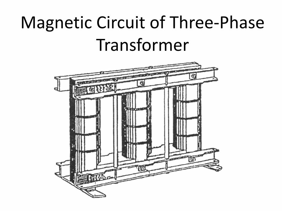
Magnetic Circuit of Three-Phase Transformer

Star (wye) Connection
UUV UU ⋅= 3
Uuv

Triangle (delta) Connection
UUV II ⋅= 3

Zigzag (Interconnected Star) Connection
UUVU
UZ UUUUU ⋅≅⋅=
+= 866,0
2330cos
22
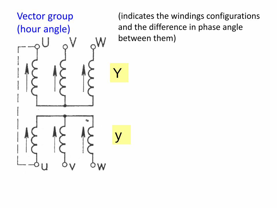
(indicates the windings configurations and the difference in phase angle between them)
Y
y
Vector group (hour angle)

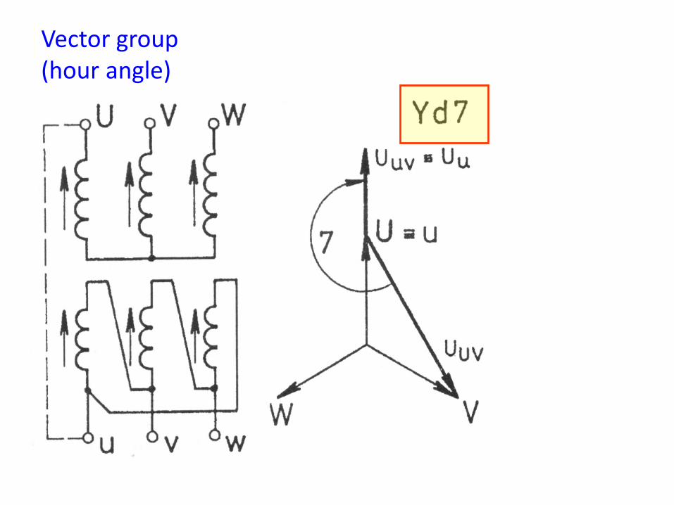
Vector group (hour angle)

Y
d
Vector group (hour angle)
Hodinový úhel Vector group (hour angle)

Parallel operation of transformers
Balancing current I2 = 0
Requirement:
0=∆⇒ U

Requirements for parallel no-load operation:
1. Same nominal voltages
3. Same vector groups (hour angles) 4. Same voltage drop caused by no-load current
2. Same turns ratio
Parallel Operation of Transformers

Requirements for parallel operation of loaded transformers:
1. Same nominal voltages
2. Same turns ratio
3. Same vector groups (hour angles)
4. Same voltage drop caused by no-load current
5. Same voltage drop when loaded
2211 IZIZ kk =
Parallel Operation of Transformers

Parallel Operation of 3 Transformers
332211 IZIZIZ kkk ==
332211 iziziz kkk ==
5. Same voltage drop when loaded
321 kkk zzz ==
321 kkk uuu ==

Autotransformer
Part of the winding common for primary and secondary
→ lower weight, costs, losses, I0 . Input – output galvanically connected.

For 12
1 >=UUp
Current I1 flows only through Aa part of the winding Lower current flows through common part of the winding
21ˆˆˆ III +=
For normal transformer:
0ˆˆˆ2211 ≅=+ µFININ
0ˆˆ 2
1 ≅+pII
Current in the common part of the autotransformer winding:
( ) ( )pIpII 111 21 −=−=
Autotransformer

For 12
1 >=UUp
Power to secondary side is transmitted in form of:
22111 IUIUS ⋅≈⋅=
Typical power: (magnetic transmission)
( ) ( )pSIUIUIUUS 111121112112 −=−=−=
Electric power: (galvanic transmission)
pSSSSel 11121 ⋅=−=
Autotransformer

Current Instrument Transformer
Load: ammeter ~ short-circuit
Range: 5 A
Current instrument transformer must not be disconnected on output side!
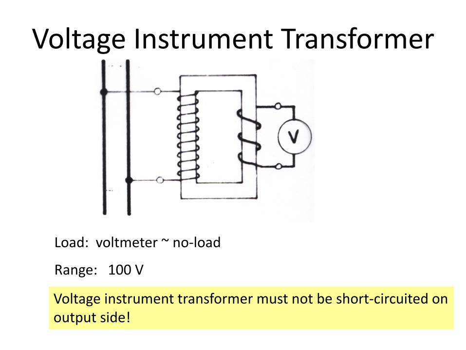
Load: voltmeter ~ no-load
Range: 100 V
Voltage instrument transformer must not be short-circuited on output side!
Voltage Instrument Transformer

Connection of Transformer in No-Load Operation to Grid
dtdNiR
dtdiRu 11
111111ϕ
⋅+⋅=Ψ
+⋅=
Supposing: ( )αω
ϕ+⋅=
⋅= tUu
LNi sin, max11
11
1111
then: ( )αωϕϕ +⋅=+⋅= tN
Udt
dLR
Nu sin
1
max11111
11
1
1
1
Solution:
( )t
LR
zb
tLR
eet 11
1
11
1
coscosmax1111
−−
±
+−−= ϕααωϕϕ
Steady magnetic flux DC component of magnetic flux
Remanent flux
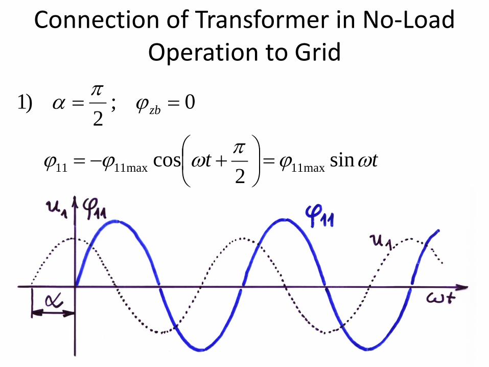
0;2
)1 == zbϕπα
tt ωϕπωϕϕ sin2
cos max11max1111 =
+−=
Connection of Transformer in No-Load Operation to Grid

0;0)2 == zbϕα)cos( 11
1
max1111
tLR
et−
+−= ωϕϕ
α
Connection of Transformer in No-Load Operation to Grid

0;0)2 == zbϕα
)cos( 11
1
max1111
tLR
et−
+−= ωϕϕ
Connection of Transformer in No-Load Operation to Grid

0;0)2 == zbϕα)cos( 11
1
max1111
tLR
et−
+−= ωϕϕ
Connection of Transformer in No-Load Operation to Grid

φ11mez ≈ 2,5 φ11max
Highest current by connection.
Connection of Transformer in No-Load Operation to Grid

Short Circuit of Transformer in Steady-State No-Load Operation
Fundamental voltage equation:
( )αω +=+= tUdtdiLiRu kk sinmax1
111
Solution for i1 = 0 at t = 0
( ) ( )
−−−+⋅=
− tLR
kkkk
k
etIi ϕαϕαω sinsin21
Angle α is determined by instant of short-circuit.
Extreme cases: 1)α = 0 2)α = φk + π/2

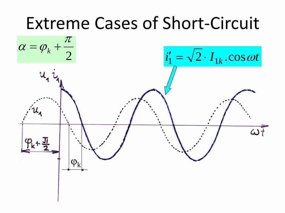
Extreme Cases of Short-Circuit
kϕα =tIi k ωsin2 11 ⋅=Solution to this is the steady
short-circuit current
φk
2πϕα += k tIi k ωcos.2 11 ⋅=′
Extreme Cases of Short-Circuit

2πϕα += k
tLR
kk
k
eIi−
=′′ 11 2
tIi k ωsin2 11 ⋅=′ tIi k ωcos2 11 ⋅⋅=′
tLR
kk
k
eIi−
−=′′ 11 2
Extreme Cases of Short-Circuit

2πϕα += k tIi k ωcos.2 11 ⋅=′
tLR
kk
k
eIi−
−=′′ ..2 11
+−=
− πk
kXR
kmez e
ZUI 12 1
1
111 iii ′′+′=
Extreme Cases of Short-Circuit

Limitation of Short-Circuit Current
11lim 2 1
k
k
RX
k
UI eZ
π− = − +
( ) ( )1lim 1 11,7 1,8 2 . 30 40k NI I tj I= ÷ ⋅ ÷ ⋅
Big transformers:
Small transformers:
( ) ( )1lim 1 11, 2 1,3 2 . 15 20k NI I tj I= ÷ ⋅ ÷ ⋅

Mechanical Stress of Transformers Forces ~ I1·I2 or more precisely I2
During short-circuit → SHORT-CIRCUIT FORCES
RADIAL

AXIAL BETWEEN THE WINDINGS
Mechanical Stress of Transformers

INSIDE THE WINDING
Mechanical Stress of Transformers

630 kVA
6 / 0,4 kV

1500 kVA
22 / 1,5 kV

400 kVA
22 / 0,4 kV

1000 kVA
22 / 0,4 kV

250 – 630 kVA
22 kV

50 – 1000 kVA
35 kV

25 MVA
110 ± 8 x 2 % / 23 kV
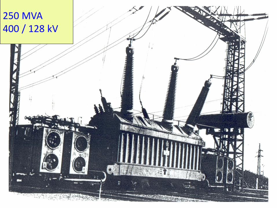
250 MVA 400 / 128 kV