Embed Size (px)
Citation preview

Donald B. Cheke www.textualcreations.ca
1
TurboCAD Pro V17.1 - Anatomy of a TurboCAD House
Donald B. Cheke

Donald B. Cheke www.textualcreations.ca
2
Copyright © 2010 Donald B. Cheke TurboCAD is a registered trademark of IMSI/Design.
Published by:
Donald B. ChekeSaskatoon, SK Canada
Visit: www.textualcreations.ca
All rights reserved No part of this document may be reproduced, copied, stored on a retrieval system or transmitted in any form without written permission from the author. The purchaser may, however, print one copy of the document to paper and may make one backup copy of the downloaded material for personal safe keeping. Limitation of Liability While every effort has been taken in the preparation and the writing of this document the author assumes no responsibility for errors and/or omissions nor for the uses of the material and the decisions based on such use. No warranties are made, express or implied with regard to either the contents of the document, its merchant ability or fitness for a particular purpose. The author should not be liable for direct, indirect, special, incidental or consequential damages arising out of the use or inability to use the contents of this document. Special Note All of the work presented within this tutorial is based on TurboCAD Pro V17.1. Although users of previous versions are welcome to try the tutorial it cannot be stated what results will be achieved. Many changes, some subtle and others not so subtle, are made with each program revision. Although many steps and directions would be generic some may not be. The same can be said for tools between versions. Older versions may not have the same tools as Pro V17.1 and if the same tools are available the tools themselves may have been revised and hence, work in a different manner than they previously did.

Donald B. Cheke www.textualcreations.ca
3
Table of Contents Table of Contents ......................................................................................................................................................... 3 Introduction .................................................................................................................................................................. 4 Setup .............................................................................................................................................................................. 6 Initial Lighting ............................................................................................................................................................. 15 Preconstruction Notes ............................................................................................................................................... 21 Basement Footings/Walls ........................................................................................................................................ 23 Main Floor Joists ........................................................................................................................................................ 46 Main Floor Sheathing ................................................................................................................................................ 52 Main Floor Walls ........................................................................................................................................................ 58 Materials Application – Session 1 .......................................................................................................................... 67 Lower Joist Area Wall ................................................................................................................................................ 94 Main Floor Interior Walls .......................................................................................................................................... 97 Main Floor Windows & Doors ............................................................................................................................... 103 Main Floor to Basement Stairs ............................................................................................................................. 125 First Floor ................................................................................................................................................................. 137 Flooring ..................................................................................................................................................................... 144 Roof/Roof Trusses .................................................................................................................................................. 156 Gable Ends ............................................................................................................................................................... 175 Box Ladders ............................................................................................................................................................. 178 Gable Walls .............................................................................................................................................................. 186 Soffits & Fascia ....................................................................................................................................................... 190 Shingles .................................................................................................................................................................... 203 Chimney ................................................................................................................................................................... 208 Rain Gutter ............................................................................................................................................................... 221 Ground ...................................................................................................................................................................... 227 Stairs & Sidewalk ................................................................................................................................................... 229 Window Sills & Headers ........................................................................................................................................ 235 Materials Application – Session 2 ....................................................................................................................... 241 Cutaway .................................................................................................................................................................... 259 Ceiling ....................................................................................................................................................................... 291 Inserting Supplied Furnishing ............................................................................................................................... 299 Named Views ........................................................................................................................................................... 301 Render Scene Luminance ..................................................................................................................................... 305 Render Scene Environment .................................................................................................................................. 308 Saving the Rendered Image ................................................................................................................................. 310 Paper Space Setup ................................................................................................................................................. 311 Printing ..................................................................................................................................................................... 321 Special Notes ........................................................................................................................................................... 323 Appendix – An Important Note about TurboCAD Materials ............................................................................. 325

Donald B. Cheke www.textualcreations.ca
4
Introduction I had been surfing the internet one day looking for tutorial inspiration when I came across a house cutaway that I just loved. I knew immediately that this was the route I wanted to go to showcase many of the TurboCAD architecture tools that exist. I made contact via email and asked if those behind the creation minded if I based my new tutorial on their idea. Matt Jennings replied that he was pleased that I liked his illustration and said that he was okay with basing the tutorial on it. Thanks Matt! See Architectural Visualization gallery at:
http://www.industrial-artworks.co.uk/pages/portfolio_vis.html
Direct link: http://www.industrial-artworks.co.uk/images/images/large_images/houseCutaway.jpg I hope that you enjoy the tutorial. Best regards, Don More and more, architects, builders and interior designers are being forced to compete in the industry by supplying top notch architectural visuals in a timely and cost effective manner. Luckily, CAD software designers such as IMSI/Design are aware of these needs and have stepped up to the plate to create a package that addresses these needs – all the while keeping in mind the budget conscious, ease of use and, of course, quality of output. TurboCAD Pro V17 (Platinum Edition) has kept up with the tradition of introducing additional architectural features, this time most notably with the addition of window muttons. Within this tutorial the new user will be introduce to many of the new and existing architectural tools and functions in a manner that should prove most enjoyable. Within the tutorial the reader will be led through each keystroke to produce all components of the cutaway house (with the exception of the furnishings which are supplied) that is illustrated on the cover of the tutorial. The reader will learn how to set up their drawing, how to insert standard lighting and how utilize render scene luminance. The reader will learn how to establish a render scene environment and the reader will learn how to render their drawing and save it in a high resolution image format. The user will also learn how to use paper space to create a single page paper presentation. This tutorial is in no way intended to teach architectural design or construction but rather it is intended to teach the use of some of the tools that TurboCAD has to offer and to introduce the new user to a drawing methodology. The author feels confident that the techniques outlined within the tutorial can help lay the foundation for future successful TurboCAD drawing and illustration for even the newest user.
As with any technically advanced software, the user is generally faced with a steep learning curve. It is the hope of the author that the money and time spent working through a Textual Creations tutorial will help ease the learning and allow the reader to come away feeling confident that they made a wise decision.

Donald B. Cheke www.textualcreations.ca
5
This tutorial will assume that the reader has the Platinum edition of TurboCAD Pro V17.1 with its extra architectural and mechanical tools, as many of the architectural tools will be looked at in detail. There are many ways to approach a project and it is likely that each person using the program would proceed in very different ways, so be open to alternative methods as experience builds. What is important is that the user becomes familiar with the objects that they wish to model and begin to look at them in a different way than they might otherwise do. What primitive shapes make up the whole? What will be required of these primitive shapes early in the drawing and how will this affect needs further along? What component or components should be started with? Many questions can only be answered through experience, but hopefully some of them will be answered by the time the beginner has worked through this tutorial. There is a great deal covered in this tutorial and the author urges the beginner to be patient, to read very carefully and to take the time necessary to do a good job. Try to enjoy the process as much as you will enjoy the final results. This tutorial assumes that the beginner has studied the desktop to some degree and can locate most of the tools. Since there are endless desktop configurations that can be set up in TurboCAD the author has opted to illustrate the required tools with the Office 2000 user interface, and the default toolbars in their undocked format (Office 2000 theme).
Please remember that any supplied images and files are for use within the tutorial only and may not be shared or sold to others. Place tutorial images in a permanent location on the hard drive.
Donald B. Cheke www.textualcreations.ca
36
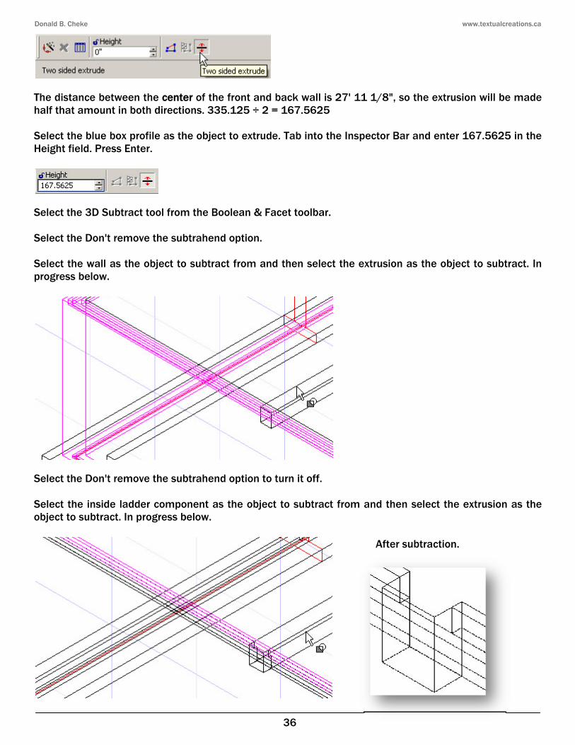
The distance between the center of the front and back wall is 27' 11 1/8", so the extrusion will be made half that amount in both directions. 335.125 ÷ 2 = 167.5625 Select the blue box profile as the object to extrude. Tab into the Inspector Bar and enter 167.5625 in the Height field. Press Enter.
Select the 3D Subtract tool from the Boolean & Facet toolbar. Select the Don't remove the subtrahend option. Select the wall as the object to subtract from and then select the extrusion as the object to subtract. In progress below.
Select the Don't remove the subtrahend option to turn it off. Select the inside ladder component as the object to subtract from and then select the extrusion as the object to subtract. In progress below.
After subtraction.

Donald B. Cheke www.textualcreations.ca
37
Select the Simple Extrude tool from the 3D Object toolbar. Select the red I=beam profile as the object to extrude. Tab into the Inspector Bar and enter 167.5625 in the Height field. Press Enter.
Select Plane by World from the Workplane toolbar.
To begin to create the posts, select the Cylinder tool from the 3D Object toolbar.
Zoom in on the left central footing and V SEKE snap the first point of the cylinder to the upper corner, as indicated in the picture below.

Donald B. Cheke www.textualcreations.ca
51
Tab into the Inspector Bar and enter 16 in the X Step field, 0 in the Y Step field, 0 in the Z Step field and 22 in the Sets field. Press Enter.
Press Ctrl + T to open the Select by Entity Type dialogue. Select Block Insertion and click OK.
Tab into the Inspector Bar and enter 0 in the Y Position field. Press Enter to center.
Press Esc to deselect the selection.

Donald B. Cheke www.textualcreations.ca
52
Main Floor Sheathing 4 x 8 x ¾" sheathing will now be placed over the joists. Turn off the Foundation Wall and FW Boxed Ladder layer. Select the Box tool from the 3D Object toolbar. Select Plane by World from the Workplane toolbar. Zoom in on the front left corner of the floor joists. V SEKE snap the first point of the box at the vertex of the far left joist as indicated in the picture below.
Tab into the Inspector Bar and enter 4' in the Width field, 8' in the Length field and .75 in the Height field. Press Enter.
Press the Space Bar to exit the tool. Select the new box. Press D SEKE and relocate (V SEKE) the reference point to the lower left forward corner of the panel as indicated in the picture below.

Donald B. Cheke www.textualcreations.ca
85
Press Ctrl + A to select all visible timbers. Select the Quality Rendering tool on the Render toolbar. Press Esc to deselect the selection after the screen renders. The grain should now be travelling in the correct direction on each timber.
Select the Wireframe tool to end the render. Select Refresh at the top of the Design Director palette to deselect any layer names.
Turn off the FW Boxed Ladder layer. Press Ctrl + A to select all visible timbers. Reassign the selection to the FW Boxed Ladder layer. Turn on the Main Floor Sheathing layer. Press Ctrl + A to select all visible timbers. Select the Quality Rendering tool on the Render toolbar. Open the Materials palette. Locate the Wood Wraps category and double click the Stand Board A thumbnail to apply the material to the selection.

Donald B. Cheke www.textualcreations.ca
86
Press Esc to deselect the selection after the screen rerenders.
Select the Wireframe tool to end the render. Turn off the Main Floor Sheathing layer and turn on the Main Floor Walls layer. Switch to Isometric SW view. Press Ctrl + A to select all visible walls. Select the Quality Rendering tool on the Render toolbar. Press Esc to deselect the selection. Open the Style Manager palette. Expand Walls Styles and select Exterior Wall 4 C. Expand Components and expand Drywall. Left mouse click in the Component Material Value field to open the initial Materials dialogue.

Donald B. Cheke www.textualcreations.ca
106
Select Add.
Adjust the Muntin Block settings to reflect those in the image below.
Click OK to exit the Muntins Block dialogue and OK to exit the Muntins dialogue.

Donald B. Cheke www.textualcreations.ca
107
Materials can be applied now or later, with the style updated at the time. Expand Materials. Left mouse click in the blank box to the right of Frame material. Select Tutorial Wall Finishes from the Category dropdown menu and select Beige A from the Material dropdown menu. Click OK. A change will be made latter if after rendering the color is a poor choice.
Left mouse click in the blank box to the right of Sash material. Select Tutorial Wall Finishes from the Category dropdown menu and select Beige A from the Material dropdown menu. Click OK. Left mouse click in the blank box to the right of Glass material. Select Glass from the Category dropdown menu and the click Edit.
Select the Create New Material icon to the right of the current material name field. Enter Anatomy House Glass in the New Material dialogue and click OK.

Donald B. Cheke www.textualcreations.ca
119
Select Finish to Edit Geometry at the top of the Style Manager palette.
On the Style Manager palette, expand Door Styles if need be.
Select Exterior Single so it is the active door and then left mouse click into the Profile selection field and select the new profile. In progress below.
All doors in the drawing change.
With the door still selected, select the Edit Tool from the Inspector Bar.
With the door now in edit mode the user will note on the Inspector Bar that the door swing can be changed.

Donald B. Cheke www.textualcreations.ca
137
Turn on the last six layers.
Switch to Front view. First Floor The first floor will be quickly created with a copy of the main floor. Select all visible objects. Select the Make Copy tool to turn it on. Note that the Make Copy tool is the only reliable copy tool to use with architectural components like Doors and Windows, otherwise they may not keep their wall associations. Tab into the Inspector Bar and enter 9'-1 3/8" in the Delta Z field. Press Enter.

Donald B. Cheke www.textualcreations.ca
158
Using four V SEKE snaps, snap around the outside perimeter of the wall cap. About to make the forth snap below. Zoom in closer than illustrated to make the snaps.
Select Finish. Select the Edit Slope Angle tool from the Architecture toolbar.
Left mouse click the lower edge of the forward slope to select it.
Close-up of first

Donald B. Cheke www.textualcreations.ca
187
Using two V SEKE snap (right to left) place a gable wall on top of the forward 1st floor wall, as indicated in the picture below. In progress below.
Select Finish. In the same manner snap a wall on the opposite side. Left to right.

Donald B. Cheke www.textualcreations.ca
188
Select Finish. Switch to Front view. Select Plane by Active View from the Workplane toolbar. Turn on the last five layers.
Select the Polyline tool from the Line toolbar. Select Blue from the color dropdown menu on the Property toolbar.
Using three V SEKE snaps, place a polyline along the bottom on the forward fascia, as indicated in the picture below. Select Finish after the third snap.
Switch to Isometric SE view. Turn off all layers, except layer 0. Select the Top Wall Modifier tool from the Architecture toolbar.
Select the forward wall as the wall to modify and then select the blue polyline as the modifier graphic. In progress below.

Donald B. Cheke www.textualcreations.ca
232
The Two sided extrude option should still be engaged. Select the stair profile as the object to extrude. Tab into the Inspector Bar and enter 30 in the Height field. Press Enter.
Select the Rotated Box tool from the 3D Object toolbar. Select Plane by World from the Workplane toolbar. Using two V SEKE snaps, place the first two points of the box, as indicated in the picture below. In progress below.
Tab into the Inspector Bar and enter -7' 3.5 in the Length field and -3.5 in the Height field. Press Enter.
Select the 3D Subtract tool from the Boolean & Facet toolbar. Select the Don't remove the subtrahend option. Select the grass as the object to subtract from and then select the sidewalk as the object to subtract. In progress below.

Donald B. Cheke www.textualcreations.ca
245
Select the Wireframe tool on the Render toolbar to stop the render. Turn off all layers, except layer 0 and then turn on the four layers indicated in the picture below.
Select all visible objects. Select the Quality Rendering tool on the Render toolbar to render the screen. Press Esc to deselect the selection after it renders. These are complete.
Select the Wireframe tool on the Render toolbar to stop the render. Turn off all layers, except layer 0 and then turn on the three layers indicated in the picture below.
Select all visible objects. Select the Quality Rendering tool on the Render toolbar to render the screen. Press Esc to deselect the selection after it renders. Only the gable walls are complete.

Donald B. Cheke www.textualcreations.ca
259
Save the file now. The cutaway will be made in a separate file. From the File menu at the top of the TurboCAD desktop select Save As. Save the file with the name Anatomy TC House Tutorial CUTAWAY.tcw.
Cutaway The wall cutaway will be made by using the Wall Modifier tool which uses a modifier graphic as a guide. Turn off all layers, except layer 0 and then turn on the Footings, Foundation Wall, Main Floor Walls, Lower Joist Area Walls, 1st Floor Walls and Upper Floor Joist Area Walls layers. Switch to Left view. Select Plane by Active View from the Workplane toolbar. Turn on the grid. Select the Line tool from the Line toolbar. Select Green from the color dropdown menu on the Property toolbar.

Donald B. Cheke www.textualcreations.ca
305
Right mouse click the Wireframe icon on the Render toolbar to open the Camera Properties. Check Quality and Click OK. Allow time for the graphics to load and the screen to render. (32 seconds on the authors off the shelf HP)
Render Scene Luminance From the View menu at the top of the TurboCAD desktop select Lights. Left mouse click the three light bulb icons to turn them off in the drawing.
Click OK to exit the Light Properties dialogue. When the scene begins to rerender press ESC to halt the render. From the Options menu at the top of the TurboCAD desktop select Render Scene Luminance. Select Single from the Category dropdown menu and select Spot from the Luminance dropdown menu. Select Edit Luminance.

Donald B. Cheke www.textualcreations.ca
321
Using two G SEKE snaps place a rectangle over the paper. Press the Space Bar to exit the tool. Select the black rectangle and then select press Shift + Page Down to move the rectangle to the back. Press Esc to deselect the selection. Double click on the signature text. Under the Text tab select Left Bottom Justification. Click OK.
With the text still selected Tab into the Inspector Bar and enter .5 in the Y Position field. Press Enter.
Press Esc to deselect the selection. Select Zoom Full View.
Printing Select the Print icon at the top of the desktop. Select Page Setup.