Embed Size (px)
Citation preview
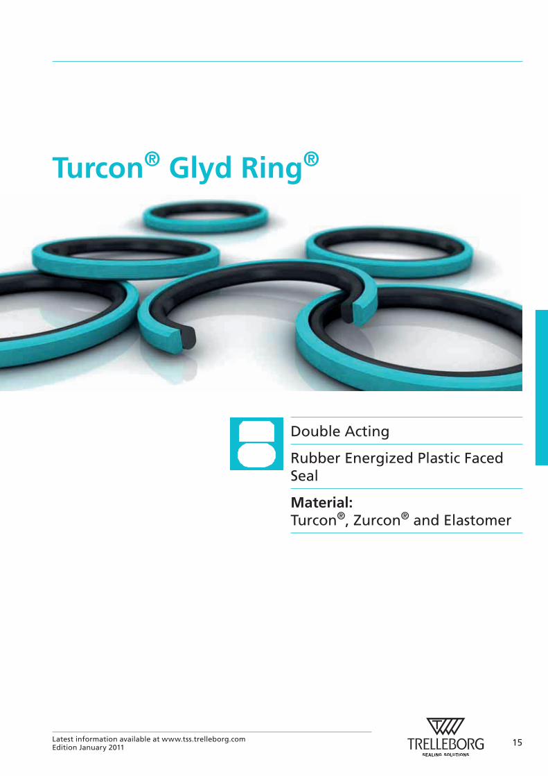
Turcon® Glyd Ring®
Double Acting
Rubber Energized Plastic Faced Seal
Material:Turcon®, Zurcon® and Elastomer
15Latest information available at www.tss.trelleborg.comEdition January 2011
16 Latest information available at www.tss.trelleborg.comEdition January 2011
Turcon® Glyd Ring®
17Latest information available at www.tss.trelleborg.comEdition January 2011
Turcon® Glyd Ring®
Turcon® Glyd Ring®
Description
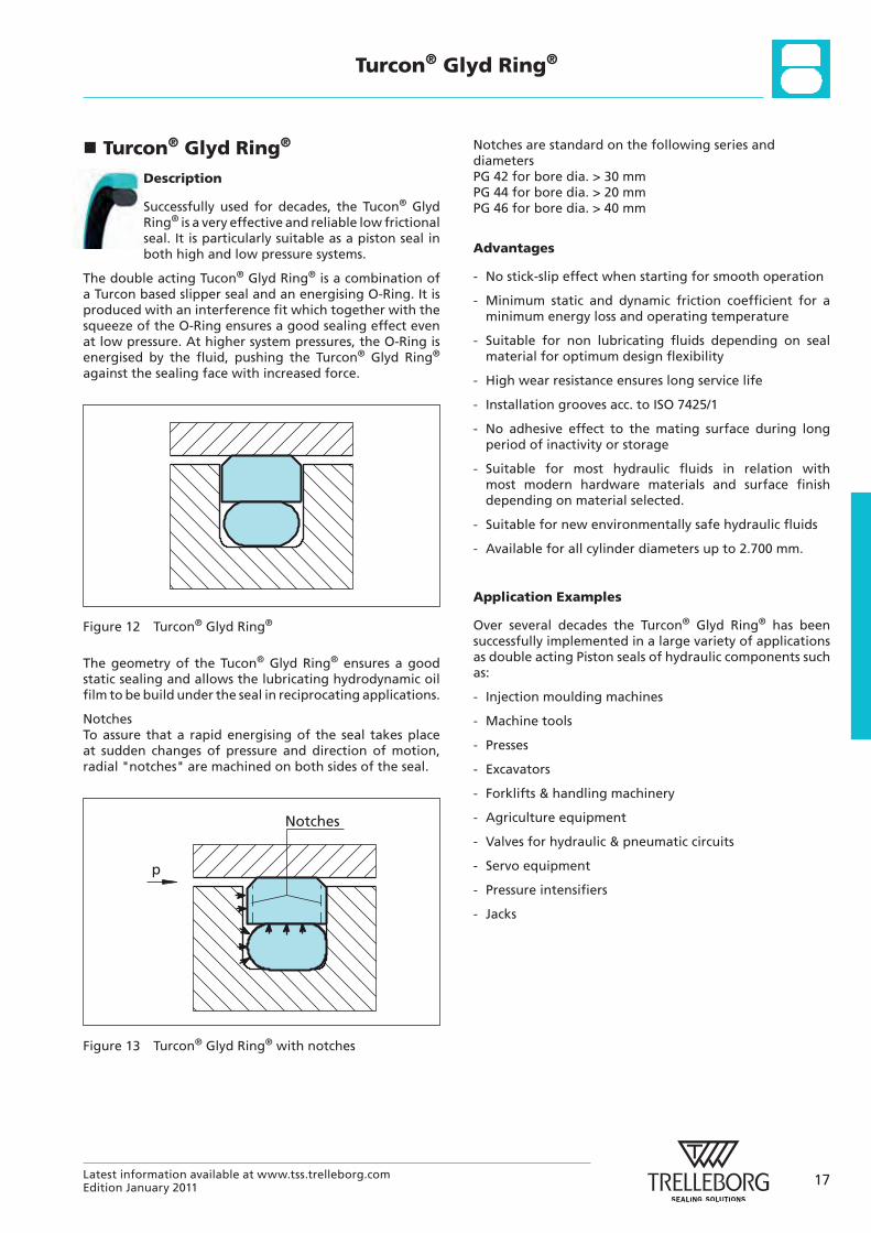
Successfully used for decades, the Tucon® Glyd Ring® is a very effective and reliable low frictional seal. It is particularly suitable as a piston seal in both high and low pressure systems.
The double acting Tucon® Glyd Ring® is a combination of a Turcon based slipper seal and an energising O-Ring. It is produced with an interference fit which together with the squeeze of the O-Ring ensures a good sealing effect even at low pressure. At higher system pressures, the O-Ring is energised by the fluid, pushing the Turcon® Glyd Ring® against the sealing face with increased force.
Figure 12 Turcon® Glyd Ring®
The geometry of the Tucon® Glyd Ring® ensures a good static sealing and allows the lubricating hydrodynamic oil film to be build under the seal in reciprocating applications.
NotchesTo assure that a rapid energising of the seal takes place at sudden changes of pressure and direction of motion, radial "notches" are machined on both sides of the seal.
Notches
p
Figure 13 Turcon® Glyd Ring® with notches
Notches are standard on the following series and diametersPG 42 for bore dia. > 30 mmPG 44 for bore dia. > 20 mmPG 46 for bore dia. > 40 mm
Advantages
- No stick-slip effect when starting for smooth operation
- Minimum static and dynamic friction coefficient for a minimum energy loss and operating temperature
- Suitable for non lubricating fluids depending on seal material for optimum design flexibility
- High wear resistance ensures long service life
- Installation grooves acc. to ISO 7425/1
- No adhesive effect to the mating surface during long period of inactivity or storage
- Suitable for most hydraulic fluids in relation with most modern hardware materials and surface finish depending on material selected.
- Suitable for new environmentally safe hydraulic fluids
- Available for all cylinder diameters up to 2.700 mm.
Application Examples
Over several decades the Turcon® Glyd Ring® has been successfully implemented in a large variety of applications as double acting Piston seals of hydraulic components such as:
- Injection moulding machines
- Machine tools
- Presses
- Excavators
- Forklifts & handling machinery
- Agriculture equipment
- Valves for hydraulic & pneumatic circuits
- Servo equipment
- Pressure intensifiers
- Jacks
18 Latest information available at www.tss.trelleborg.comEdition January 2011
Turcon® Glyd Ring®
Technical Data
Operating conditions:
The Turcon® Glyd Ring® is recommended for reciprocating (with a length of stroke at least twice the groove width) and helical movements.
Pressure: Up to 60 MPa
Speed: Up to 15 m/s
Frequency: Up to 5 Hz.
Temperature: -45 °C to +200 °C *) (depending on O-Ring Material)
Media: Mineral oil based hydraulic fluids, flame retardant hydraulic fluids, environmentally safe hydraulic fluids (bio-oils), phosphate ester, water and others, depending on the seal and O-Ring material compatibility (see Table X)
Clearance: The maximum permissible radial clearance Smax is shown in the Table XI as a function of the operating pressure and functional diameter.
Important Note:The above data are maximum values and cannot be used at the same time. e.g. the maximum operating speed depends on material type, pressure, temperature and gap value. Temperature range also dependent on medium.
*) In the case of unpressurized applications in temperatures below 0°C please contact ourapplication engineers for assistance!
Materials
The following material combinations have proven effective for hydraulic applications:
For light to heavy applications with reciprocating movements in mineral oils and other media with good lubrication:
All round material for hydraulic applications with reciprocating, short stroke or helical movements in mineral oils, flame retardant hydraulic fluids HFC, phosphate ester, bio-oils or fluids having less satisfactory lubricating properties:
Turcon® Glyd Ring®: Turcon® M12
O-Ring: NBR, 70 Shore A N FKM, 70 Shore A V
Set code: M12N or M12V
For medium to heavy applications with reciprocating movements in mineral oils and other media with good lubrication:
Turcon® Glyd Ring®: Turcon® T46
O-Ring: NBR, 70 Shore A N FKM, 70 Shore A V
Set code: T46N or T46V
For specific applications, all Turcon® materials are available. Other viable material combinations are listed in Table IX.
19Latest information available at www.tss.trelleborg.comEdition January 2011
Turcon® Glyd Ring®
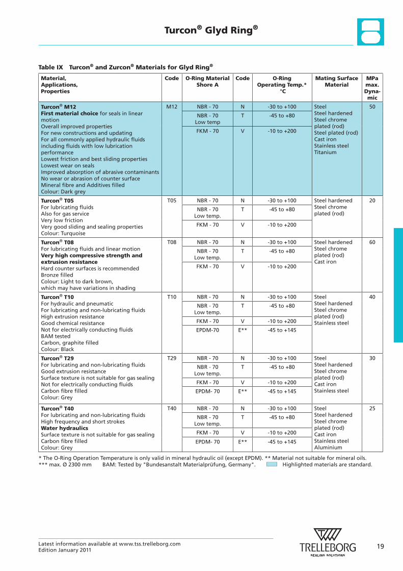
Table IX Turcon® and Zurcon® Materials for Glyd Ring®
Material, Applications, Properties
Code O-Ring Material Shore A
Code O-Ring Operating Temp.*
°C
Mating Surface Material
MPa max. Dyna- mic
Turcon® M12First material choice for seals in linear motion Overall improved properties For new constructions and updating For all commonly applied hydraulic fluids including fluids with low lubrication performance Lowest friction and best sliding properties Lowest wear on seals Improved absorption of abrasive contaminants No wear or abrasion of counter surface Mineral fibre and Additives filled Colour: Dark grey
M12 NBR - 70 N -30 to +100 Steel Steel hardened Steel chrome plated (rod) Steel plated (rod) Cast iron Stainless steel Titanium
50
NBR - 70 Low temp
T -45 to +80
FKM - 70 V -10 to +200
Turcon® T05For lubricating fluids Also for gas service Very low friction Very good sliding and sealing properties Colour: Turquoise
T05 NBR - 70 N -30 to +100 Steel hardened Steel chrome plated (rod)
20
NBR - 70 Low temp.
T -45 to +80
FKM - 70 V -10 to +200
Turcon® T08For lubricating fluids and linear motion Very high compressive strength and extrusion resistance Hard counter surfaces is recommended Bronze filled Colour: Light to dark brown, which may have variations in shading
T08 NBR - 70 N -30 to +100 Steel hardened Steel chrome plated (rod) Cast iron
60
NBR - 70 Low temp.
T -45 to +80
FKM - 70 V -10 to +200
Turcon® T10For hydraulic and pneumatic For lubricating and non-lubricating fluids High extrusion resistance Good chemical resistance Not for electrically conducting fluids BAM tested Carbon, graphite filled Colour: Black
T10 NBR - 70 N -30 to +100 Steel Steel hardened Steel chrome plated (rod)Stainless steel
40
NBR - 70 Low temp.
T -45 to +80
FKM - 70 V -10 to +200
EPDM-70 E** -45 to +145
Turcon® T29For lubricating and non-lubricating fluids Good extrusion resistance Surface texture is not suitable for gas sealing Not for electrically conducting fluids Carbon fibre filled Colour: Grey
T29 NBR - 70 N -30 to +100 Steel Steel hardened Steel chrome plated (rod) Cast iron Stainless steel
30
NBR - 70 Low temp.
T -45 to +80
FKM - 70 V -10 to +200
EPDM- 70 E** -45 to +145
Turcon® T40For lubricating and non-lubricating fluids High frequency and short strokes Water hydraulics Surface texture is not suitable for gas sealing Carbon fibre filled Colour: Grey
T40 NBR - 70 N -30 to +100 Steel Steel hardened Steel chrome plated (rod) Cast iron Stainless steel Aluminium
25
NBR - 70 Low temp.
T -45 to +80
FKM - 70 V -10 to +200
EPDM- 70 E** -45 to +145
* The O-Ring Operation Temperature is only valid in mineral hydraulic oil (except EPDM). ** Material not suitable for mineral oils. *** max. Ø 2300 mm BAM: Tested by "Bundesanstalt Materialprüfung, Germany". Highlighted materials are standard.
20 Latest information available at www.tss.trelleborg.comEdition January 2011
Turcon® Glyd Ring®
Material, Applications, Properties
Code O-Ring Material Shore A
Code O-Ring Operating Temp.*
°C
Mating Surface Material
MPa max. Dyna- mic
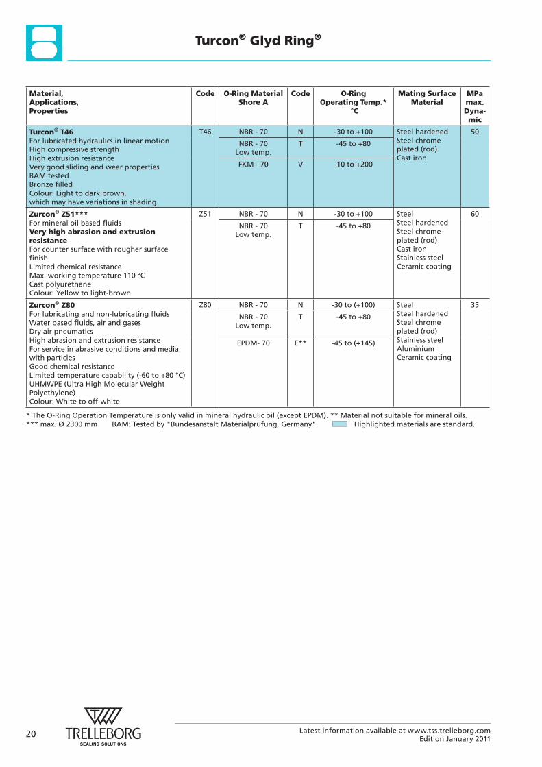
Turcon® T46For lubricated hydraulics in linear motion High compressive strength High extrusion resistance Very good sliding and wear properties BAM tested Bronze filled Colour: Light to dark brown, which may have variations in shading
T46 NBR - 70 N -30 to +100 Steel hardened Steel chrome plated (rod) Cast iron
50
NBR - 70 Low temp.
T -45 to +80
FKM - 70 V
-10 to +200
Zurcon® Z51***For mineral oil based fluids Very high abrasion and extrusion resistanceFor counter surface with rougher surface finish Limited chemical resistance Max. working temperature 110 °C Cast polyurethane Colour: Yellow to light-brown
Z51 NBR - 70 N -30 to +100 Steel Steel hardened Steel chrome plated (rod) Cast iron Stainless steel Ceramic coating
60
NBR - 70 Low temp.
T -45 to +80
Zurcon® Z80For lubricating and non-lubricating fluids Water based fluids, air and gases Dry air pneumatics High abrasion and extrusion resistance For service in abrasive conditions and media with particles Good chemical resistance Limited temperature capability (-60 to +80 °C) UHMWPE (Ultra High Molecular Weight Polyethylene) Colour: White to off-white
Z80 NBR - 70 N -30 to (+100) Steel Steel hardened Steel chrome plated (rod) Stainless steel Aluminium Ceramic coating
35
NBR - 70 Low temp.
T -45 to +80
EPDM- 70 E** -45 to (+145)
* The O-Ring Operation Temperature is only valid in mineral hydraulic oil (except EPDM). ** Material not suitable for mineral oils. *** max. Ø 2300 mm BAM: Tested by "Bundesanstalt Materialprüfung, Germany". Highlighted materials are standard.
21Latest information available at www.tss.trelleborg.comEdition January 2011
Turcon® Glyd Ring®
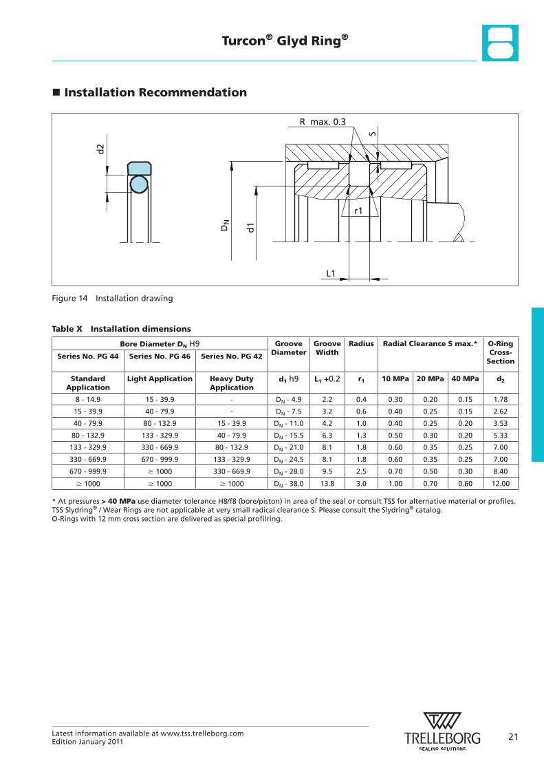
Installation Recommendation
R max. 0.3
L1
r1
S
DN
d1
d2
Figure 14 Installation drawing
Table X Installation dimensions
Bore Diameter DN H9 Groove Diameter
Groove Width
Radius Radial Clearance S max.* O-Ring Cross-
SectionSeries No. PG 44 Series No. PG 46 Series No. PG 42
Standard Application
Light Application Heavy Duty Application
d1 h9 L1 +0.2 r1 10 MPa 20 MPa 40 MPa d2
8 - 14.9 15 - 39.9 - DN - 4.9 2.2 0.4 0.30 0.20 0.15 1.78
15 - 39.9 40 - 79.9 - DN - 7.5 3.2 0.6 0.40 0.25 0.15 2.62
40 - 79.9 80 - 132.9 15 - 39.9 DN - 11.0 4.2 1.0 0.40 0.25 0.20 3.53
80 - 132.9 133 - 329.9 40 - 79.9 DN - 15.5 6.3 1.3 0.50 0.30 0.20 5.33
133 - 329.9 330 - 669.9 80 - 132.9 DN - 21.0 8.1 1.8 0.60 0.35 0.25 7.00
330 - 669.9 670 - 999.9 133 - 329.9 DN - 24.5 8.1 1.8 0.60 0.35 0.25 7.00
670 - 999.9 � 1000 330 - 669.9 DN - 28.0 9.5 2.5 0.70 0.50 0.30 8.40
� 1000 � 1000 � 1000 DN - 38.0 13.8 3.0 1.00 0.70 0.60 12.00
* At pressures > 40 MPa use diameter tolerance H8/f8 (bore/piston) in area of the seal or consult TSS for alternative material or profiles.TSS Slydring® / Wear Rings are not applicable at very small radical clearance S. Please consult the Slydring® catalog. O-Rings with 12 mm cross section are delivered as special profilring.
22 Latest information available at www.tss.trelleborg.comEdition January 2011
Turcon® Glyd Ring®
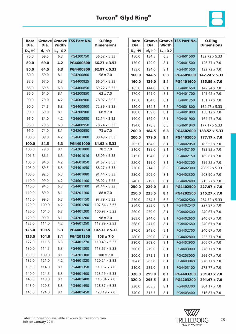
Bore Dia.
Groove Dia.
Groove Width
TSS Part No. O-Ring Dimensions
DN H9 d1 h9 L1 +0.2
8.0
10.0
12.0
3.1
5.1
7.1
2.2
2.2
2.2
PG4400080
PG4400100
PG4400120
2.90 x 1.78
4.80 x 1.8
6.70 x 1.8
14.0
15.0
16.0
9.1
7.5
11.1
2.2
3.2
2.2
PG4400140
PG4400150
PG4600160
8.75 x 1.8
7.59 x 2.62
10.82 x 1.78
16.0
18.0
18.0
8.5
13.1
10.5
3.2
2.2
3.2
PG4400160
PG4600180
PG4400180
7.59 x 2.62
12.42 x 1.78
9.19 x 2.62
19.05
20.0
20.0
11.55
15.1
12.5
3.2
2.2
3.2
PG4400190
PG4600200
PG4400200
10.77 x 2.62
14.00 x 1.78
12.37 x 2.62
21.0
22.0
22.0
13.5
17.1
14.5
3.2
2.2
3.2
PG4400210
PG4600220
PG4400220
12.37 x 2.62
17.17 x 1.78
13.94 x 2.62
24.0
25.0
25.0
16.5
20.1
17.5
3.2
2.2
3.2
PG4400240
PG4600250
PG4400250
15.54 x 2.62
18.77 x 1.78
17.12 x 2.62
25.0
25.4
28.0
14.0
20.5
20.5
4.2
2.2
3.2
PG4200250
PG4600254
PG4400280
13.87 x 3.53
17.12 x 2.62
20.29 x 2.62
30.0
32.0
32.0
22.5
27.1
24.5
3.2
2.2
3.2
PG4400300
PG4600320
PG4400320
21.89 x 2.62
26.70 x 1.78
23.47 x 2.62
32.0
35.0
35.0
21.0
27.5
24.0
4.2
3.2
4.2
PG4200320
PG4400350
PG4200350
20.22 x 3.53
26.64 x 2.62
23.40 x 3.53
Bore Dia.
Groove Dia.
Groove Width
TSS Part No. O-Ring Dimensions
DN H9 d1 h9 L1 +0.2
36.0
38.0
40.0
28.5
30.5
32.5
3.2
3.2
3.2
PG4400360
PG4400380
PG4600400
28.24 x 2.62
29.82 x 2.62
31.42 x 2.62
40.0
42.0
44.45
29.0
31.0
36.95
4.2
4.2
3.2
PG4400400
PG4400420
PG4600444
28.17 x 3.53
29.75 x 3.53
36.17 x 2.62
45.0
48.0
50.0
34.0
37.0
42.5
4.2
4.2
3.2
PG4400450
PG4400480
PG4600500
32.92 x 3.53
36.09 x 3.53
40.94 x 2.62
50.0
50.0
50.8
39.0
34.5
43.3
4.2
6.3
3.2
PG4400500
PG4200500
PG4600508
37.70 x 3.53
32.69 x 5.33
42.52 x 2.62
50.8
52.0
53.0
39.8
41.0
42.0
4.2
4.2
4.2
PG4400508
PG4400520
PG4400530
37.70 x 3.53
40.87 x 3.53
40.87 x 3.53
55.0
57.0
58.0
44.0
46.0
47.0
4.2
4.2
4.2
PG4400550
PG4400570
PG4400580
44.04 x 3.53
44.04 x 3.53
47.22 x 3.53
60.0
62.0
63.0
49.0
51.0
52.0
4.2
4.2
4.2
PG4400600
PG4400620
PG4400630
47.22 x 3.53
50.39 x 3.53
50.39 x 3.53
63.0
65.0
68.0
47.5
54.0
57.0
6.3
4.2
4.2
PG4200630
PG4400650
PG4400680
46.99 x 5.33
53.57 x 3.53
56.74 x 3.53
70.0
70.0
75.0
59.0
54.5
64.0
4.2
6.3
4.2
PG4400700
PG4200700
PG4400750
56.74 x 3.53
53.34 x 5.33
63.09 x 3.53
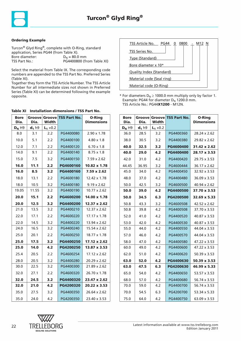
Table XI Installation dimensions / TSS Part No.
Ordering Example
Turcon® Glyd Ring®, complete with O-Ring, standard application, Series PG44 (from Table X).Bore diameter: DN = 80.0 mmTSS Part No.: PG4400800 (from Table XI)
Select the material from Table IX. The corresponding code numbers are appended to the TSS Part No. Preferred Series (Table XI).Together they form the TSS Article Number. The TSS Article Number for all intermediate sizes not shown in Preferred Series (Table XI) can be determined following the example opposite.
Material code (Seal ring)
TSS Series No.
TSS Article No. M120800 N
Material code (O-Ring)
Bore diameter x 10*
PG44
Quality Index (Standard)
-
Type (Standard)
0
* For diameters DN 1000.0 mm multiply only by factor 1.Example: PG44 for diameter DN 1200.0 mm.TSS Article No.: PG44X1200 - M12N.
23Latest information available at www.tss.trelleborg.comEdition January 2011
Turcon® Glyd Ring®
Bore Dia.
Groove Dia.
Groove Width
TSS Part No. O-Ring Dimensions
DN H9 d1 h9 L1 +0.2
75.0
80.0
80.0
59.5
69.0
64.5
6.3
4.2
6.3
PG4200750
PG4600800
PG4400800
56.52 x 5.33
66.27 x 3.53
62.87 x 5.33
80.0
82.5
85.0
59.0
67.0
69.5
8.1
6.3
6.3
PG4200800
PG4400825
PG4400850
58 x 7.0
66.04 x 5.33
69.22 x 5.33
85.0
90.0
90.0
64.0
79.0
74.5
8.1
4.2
6.3
PG4200850
PG4600900
PG4400900
63 x 7.0
78.97 x 3.53
72.39 x 5.33
90.0
95.0
95.0
69.0
84.0
79.5
8.1
4.2
6.3
PG4200900
PG4600950
PG4400950
68 x 7.0
82.14 x 3.53
78.74 x 5.33
95.0
100.0
100.0
74.0
89.0
84.5
8.1
4.2
6.3
PG4200950
PG4601000
PG4401000
73 x 7.0
88.49 x 3.53
81.92 x 5.33
100.0
101.6
105.0
79.0
86.1
94.0
8.1
6.3
4.2
PG4201000
PG4401016
PG4601050
78 x 7.0
85.09 x 5.33
91.67 x 3.53
105.0
108.0
110.0
89.5
92.5
99.0
6.3
6.3
4.2
PG4401050
PG4401080
PG4601100
88.27 x 5.33
91.44 x 5.33
98.02 x 3.53
110.0
110.0
115.0
94.5
89.0
99.5
6.3
8.1
6.3
PG4401100
PG4201100
PG4401150
91.44 x 5.33
88 x 7.0
97.79 x 5.33
120.0
120.0
120.0
109.0
104.5
99.0
4.2
6.3
8.1
PG4601200
PG4401200
PG4201200
107.54 x 3.53
100.97 x 5.33
98 x 7.0
125.0
125.0
125.0
114.0
109.5
104.0
4.2
6.3
8.1
PG4601250
PG4401250
PG4201250
113.89 x 3.53
107.32 x 5.33
103 x 7.0
127.0
130.0
130.0
111.5
114.5
109.0
6.3
6.3
8.1
PG4401270
PG4401300
PG4201300
110.49 x 5.33
113.67 x 5.33
108 x 7.0
132.0
135.0
140.0
121.0
114.0
124.5
4.2
8.1
6.3
PG4601320
PG4401350
PG4601400
120.24 x 3.53
113.67 x 7.0
123.19 x 5.33
140.0
145.0
145.0
119.0
129.5
124.0
8.1
6.3
8.1
PG4401400
PG4601450
PG4401450
116.84 x 7.0
126.37 x 5.33
123.19 x 7.0
Bore Dia.
Groove Dia.
Groove Width
TSS Part No. O-Ring Dimensions
DN H9 d1 h9 L1 +0.2
150.0
150.0
155.0
134.5
129.0
134.0
6.3
8.1
8.1
PG4601500
PG4401500
PG4401550
132.72 x 5.33
126.37 x 7.0
132.72 x 7.0
160.0
160.0
165.0
144.5
139.0
144.0
6.3
8.1
8.1
PG4601600
PG4401600
PG4401650
142.24 x 5.33
135.89 x 7.0
142.24 x 7.0
170.0
175.0
180.0
149.0
154.0
164.5
8.1
8.1
6.3
PG4401700
PG4401750
PG4601800
145.42 x 7.0
151.77 x 7.0
164.47 x 5.33
180.0
190.0
194.0
159.0
169.0
178.5
8.1
8.1
6.3
PG4401800
PG4401900
PG4601940
158.12 x 7.0
164.47 x 7.0
177.17 x 5.33
200.0
200.0
205.0
184.5
179.0
184.0
6.3
8.1
8.1
PG4602000
PG4402000
PG4402050
183.52 x 5.33
177.17 x 7.0
183.52 x 7.0
210.0
215.0
220.0
189.0
194.0
199.0
8.1
8.1
8.1
PG4402100
PG4402150
PG4402200
183.52 x 7.0
189.87 x 7.0
196.22 x 7.0
230.0
230.0
240.0
214.5
209.0
219.0
6.3
8.1
8.1
PG4602300
PG4402300
PG4402400
208.92 x 5.33
208.90 x 7.0
215.27 x 7.0
250.0
250.0
250.0
229.0
225.5
234.5
8.1
8.1
6.3
PG4402500
PG4202500
PG4602500
227.97 x 7.0
215.27 x 7.0
234.32 x 5.33
254.0
260.0
265.0
233.0
239.0
244.0
8.1
8.1
8.1
PG4402540
PG4402600
PG4402650
227.97 x 7.0
240.67 x 7.0
240.67 x 7.0
268.0
270.0
280.0
247.0
249.0
259.0
8.1
8.1
8.1
PG4402680
PG4402700
PG4402800
240.67 x 7.0
240.67 x 7.0
253.37 x 7.0
290.0
300.0
300.0
269.0
279.0
275.5
8.1
8.1
8.1
PG4402900
PG4403000
PG4203000
266.07 x 7.0
278.77 x 7.0
266.07 x 7.0
304.8
310.0
320.0
283.8
289.0
299.0
8.1
8.1
8.1
PG4403048
PG4403100
PG4403200
278.77 x 7.0
278.77 x 7.0
291.47 x 7.0
320.0
330.0
340.0
295.5
305.5
315.5
8.1
8.1
8.1
PG4203200
PG4403300
PG4403400
291.47 x 7.0
304.17 x 7.0
316.87 x 7.0
24 Latest information available at www.tss.trelleborg.comEdition January 2011
Turcon® Glyd Ring®
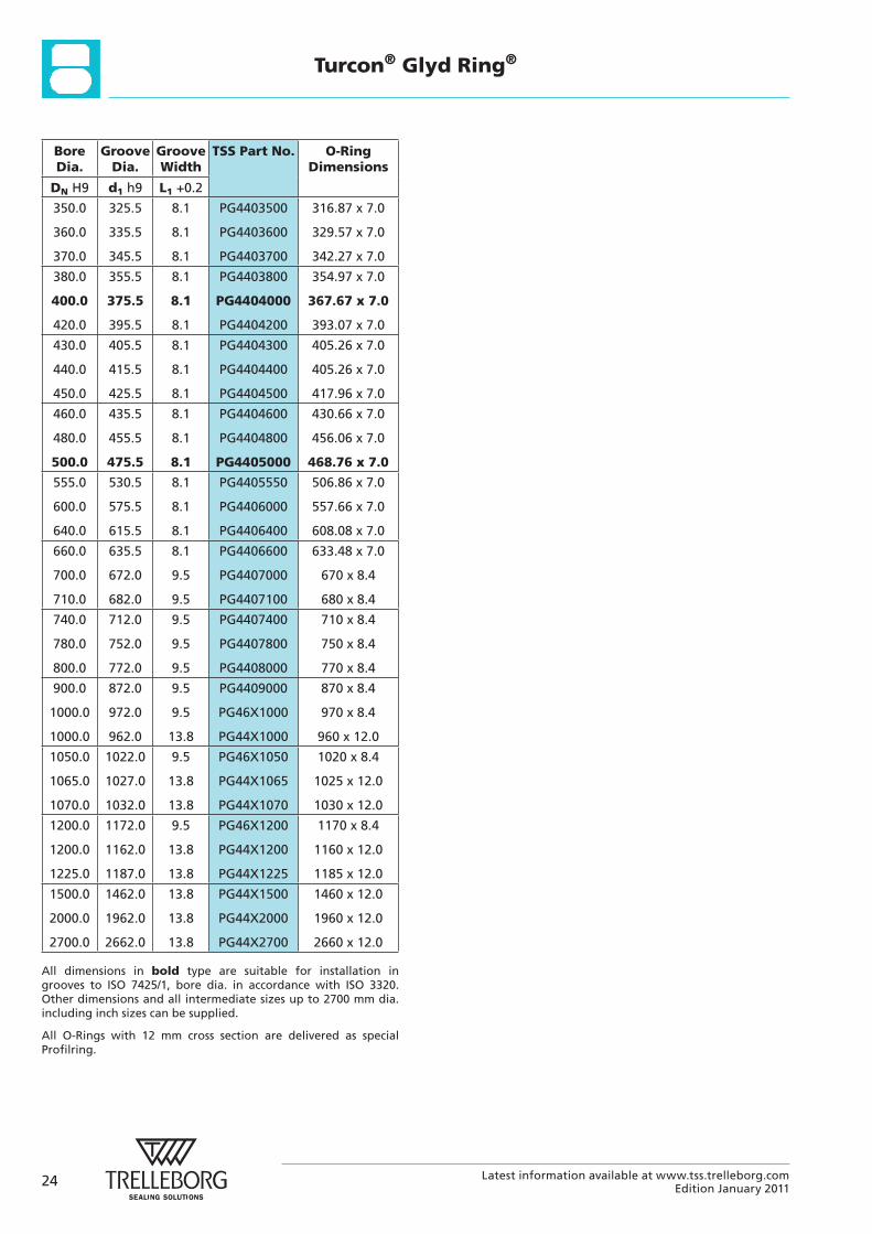
Bore Dia.
Groove Dia.
Groove Width
TSS Part No. O-Ring Dimensions
DN H9 d1 h9 L1 +0.2
350.0
360.0
370.0
325.5
335.5
345.5
8.1
8.1
8.1
PG4403500
PG4403600
PG4403700
316.87 x 7.0
329.57 x 7.0
342.27 x 7.0
380.0
400.0
420.0
355.5
375.5
395.5
8.1
8.1
8.1
PG4403800
PG4404000
PG4404200
354.97 x 7.0
367.67 x 7.0
393.07 x 7.0
430.0
440.0
450.0
405.5
415.5
425.5
8.1
8.1
8.1
PG4404300
PG4404400
PG4404500
405.26 x 7.0
405.26 x 7.0
417.96 x 7.0
460.0
480.0
500.0
435.5
455.5
475.5
8.1
8.1
8.1
PG4404600
PG4404800
PG4405000
430.66 x 7.0
456.06 x 7.0
468.76 x 7.0
555.0
600.0
640.0
530.5
575.5
615.5
8.1
8.1
8.1
PG4405550
PG4406000
PG4406400
506.86 x 7.0
557.66 x 7.0
608.08 x 7.0
660.0
700.0
710.0
635.5
672.0
682.0
8.1
9.5
9.5
PG4406600
PG4407000
PG4407100
633.48 x 7.0
670 x 8.4
680 x 8.4
740.0
780.0
800.0
712.0
752.0
772.0
9.5
9.5
9.5
PG4407400
PG4407800
PG4408000
710 x 8.4
750 x 8.4
770 x 8.4
900.0
1000.0
1000.0
872.0
972.0
962.0
9.5
9.5
13.8
PG4409000
PG46X1000
PG44X1000
870 x 8.4
970 x 8.4
960 x 12.0
1050.0
1065.0
1070.0
1022.0
1027.0
1032.0
9.5
13.8
13.8
PG46X1050
PG44X1065
PG44X1070
1020 x 8.4
1025 x 12.0
1030 x 12.0
1200.0
1200.0
1225.0
1172.0
1162.0
1187.0
9.5
13.8
13.8
PG46X1200
PG44X1200
PG44X1225
1170 x 8.4
1160 x 12.0
1185 x 12.0
1500.0
2000.0
2700.0
1462.0
1962.0
2662.0
13.8
13.8
13.8
PG44X1500
PG44X2000
PG44X2700
1460 x 12.0
1960 x 12.0
2660 x 12.0
All dimensions in bold type are suitable for installation in grooves to ISO 7425/1, bore dia. in accordance with ISO 3320. Other dimensions and all intermediate sizes up to 2700 mm dia. including inch sizes can be supplied.
All O-Rings with 12 mm cross section are delivered as special Profilring.
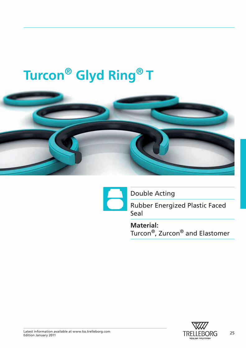
Turcon® Glyd Ring® T
Double Acting
Rubber Energized Plastic Faced Seal
Material:Turcon®, Zurcon® and Elastomer
25Latest information available at www.tss.trelleborg.comEdition January 2011

26 Latest information available at www.tss.trelleborg.comEdition January 2011
27Latest information available at www.tss.trelleborg.comEdition January 2011
Turcon® Glyd Ring® T
Turcon® Glyd Ring® T*Description
Turcon® Glyd Ring® T is a further technical development of the Turcon® Glyd Ring® seal which has been successfully used for decades. It is fully interchangeable with the earlier Glyd
Ring® seals in all new applications. Glyd Ring® T meets all the market demands for a function-specific seal solution, observing economic and ecological aspects.
The benefits of the patented seal concept are provided by the innovative functional principle of the trapezoidal profile cross-section.
Both lateral profile flanks are inclined so that the seal profile tapers towards the seal surface. The profile can thus retain the robust and compact form typical of piston seals without losing any of the flexibility required to achieve a pressure-related maximum compression (Figure 15).
p
Turcon® Seal ring
O-Ring
Figure 15 Turcon® Glyd Ring® T
The edge angle created by the special Glyd Ring® T crosssectional form permits an additional degree of freedom and enables a slight tilting movement of the seal. The maximum compression is thus always shifted towards the area of the seal edge directly exposed to the pressure. On the low-pressure edge of the seal, on the other hand, the Glyd Ring® T exhibits only zones with neutral strains without compressive or shearing loads, thus effectively reducing the danger of gap extrusion. The resulting benefits for the user can be seen in the following list.
Advantages
The benefits offered to date by the Glyd Ring® are still retained in full, and are now complemented by a number of further important advantages:
- Very good static leak-tightness
- Increased clearance possible (approx. +50%), depending on the operating conditions
- Due to the larger extrusion gap, safe use even with soiled media
- Low friction, no stick-slip effect
- Simple groove design, one-piece pistons possible
- Installation grooves to ISO 7425/1
- Adaptable to the operating conditions due to a wide range of possible materials (Turcon®, Zurcon®)
- Suitable for new environmentally safe hydraulic fluids
- Available for all cylinder diameters up to 2.700 mm.
Application Examples
The Turcon® Glyd Ring® T is the recommended sealing element for double acting pistons of hydraulic components such as:
- Injection moulding machines
- Machine tools
- Presses
- Excavators
- Forklifts & handling machinery
- Agriculture
- Valves for hydraulic & pneumatic circuits.
- Servo equipment
- Pressure intensifiers
- Jacks
It is particularly recommended for heavy duty and large diameter applications.
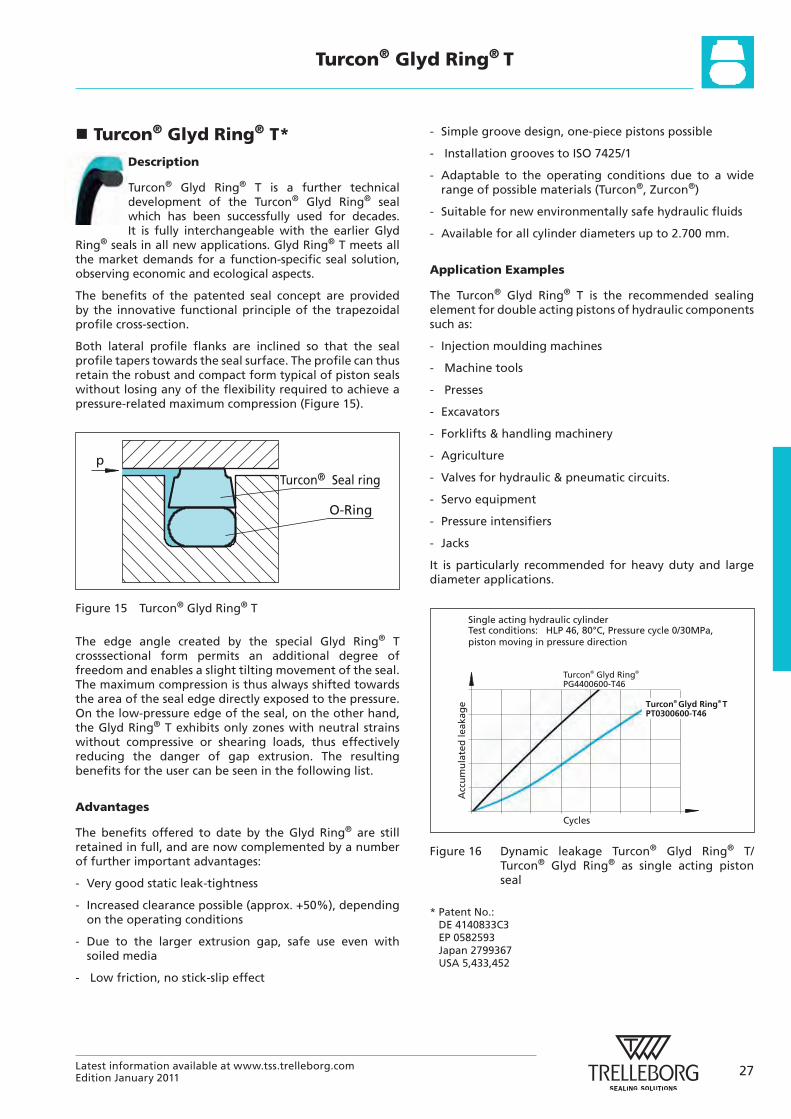
Single acting hydraulic cylinderTest conditions: HLP 46, 80°C, Pressure cycle 0/30MPa,piston moving in pressure direction
Cycles
Acc
um
ula
ted
leak
age
Turcon® Glyd Ring® PG4400600-T46
Turcon® Glyd Ring® T
PT0300600-T46
Figure 16 Dynamic leakage Turcon® Glyd Ring® T/ Turcon® Glyd Ring® as single acting piston seal
* Patent No.: DE 4140833C3 EP 0582593 Japan 2799367 USA 5,433,452
28 Latest information available at www.tss.trelleborg.comEdition January 2011
Turcon® Glyd Ring® T
Technical Data
Operating conditions
Pressure: Up to 60 MPa
Speed: Up to 15 m/s Temperature: -45 °C to +200 °C *)
(depending on O-Ring material).
Media: Mineral oil-based hydraulic fluids, flame retardant hydraulic fluids, environmentally safe hydraulic fluids (bio-oils), phosphate ester, water, air and others, depending on the seal and O-Ring material compatibility (see Table XIII)
Clearance: The maximum permissible radial clearance smax is shown in Table XIV, as a function of the operating pressure and functional diameter.
Important Note:The above data are maximum values and cannot be used at the same time. e.g. the maximum operating speed depends on material type, pressure, temperature and gap value. Temperature range also dependent on medium.
*) In the case of unpressurized applications in temperatures below 0°C please contact ourapplication engineers for assistance!
Materials
The following material combinations have proven effective for hydraulic applications:
All round material for hydraulic applications with reciprocating or short stroke in mineral oils, flame retardant hydarulic fluids HFC, phosphate ester, bio-oils or fluids having less satisfactory properties.
Turcon® Glyd Ring® T: Turcon® M12
O-Ring: NBR, 70 Shore A N FKM, 70 Shore A V
Set code: M12N or M12V
For medium to heavy applications with reciprocating movements in mineral oils and other media with good lubrication:Turcon® Glyd Ring® T: Turcon® T46
O-Ring: NBR, 70 Shore A N FKM, 70 Shore A V
Set code: T46N or T46V
For specific applications, other viable material combinations are listed in Table XIII.
Series
Different cross-section sizes are recommended as a function of the seal diameters.
Table XII, shows the relationship between the series number according to the seal diameter range and the different application class sizes. These application classes are:
Standard application: General applications in which no exceptional operating conditions exist.
Light application: Applications with demands for reduced friction or for smaller grooves.
Heavy-duty application: For exceptional operating loads such as high pressures, pressure peaks, etc.
Table XII Available range
Series No. Piston Diameter DN H9
PT00 8.0 - 140.0
PT01 8.0 - 200.0
PT02 16.0 - 380.0
PT03 40.0 - 480.0
PT04 80.0 - 700.0
PT08 133.0 - 999.9
PT05 310.0 - 999.9
PT05X 1000.0 - 1200.0
PT06 750.0 - 999.9
PT06X 1000.0 - 2700.0
For the recommended range see Table XIV.
29Latest information available at www.tss.trelleborg.comEdition January 2011
Turcon® Glyd Ring® T
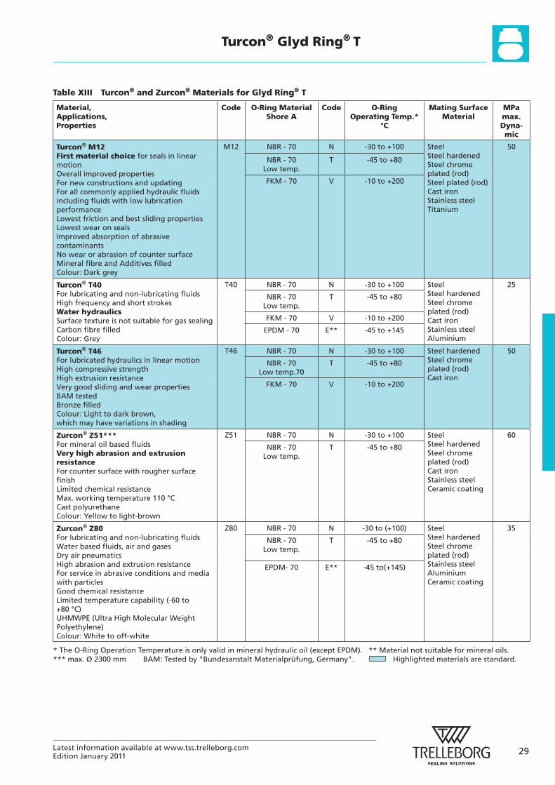
Table XIII Turcon® and Zurcon® Materials for Glyd Ring® T
Material, Applications, Properties
Code
O-Ring Material Shore A
Code
O-Ring Operating Temp.*
°C
Mating Surface Material
MPa max. Dyna- mic
Turcon® M12 First material choice for seals in linear motion Overall improved properties For new constructions and updating For all commonly applied hydraulic fluids including fluids with low lubrication performance Lowest friction and best sliding properties Lowest wear on seals Improved absorption of abrasive contaminants No wear or abrasion of counter surface Mineral fibre and Additives filled Colour: Dark grey
M12 NBR - 70 N -30 to +100 Steel Steel hardened Steel chrome plated (rod) Steel plated (rod) Cast iron Stainless steel Titanium
50
NBR - 70 Low temp.
T -45 to +80
FKM - 70 V -10 to +200
Turcon® T40 For lubricating and non-lubricating fluids High frequency and short strokes Water hydraulics Surface texture is not suitable for gas sealing Carbon fibre filled Colour: Grey
T40 NBR - 70 N -30 to +100 Steel Steel hardened Steel chrome plated (rod) Cast iron Stainless steel Aluminium
25
NBR - 70 Low temp.
T -45 to +80
FKM - 70 V -10 to +200
EPDM - 70 E** -45 to +145
Turcon® T46 For lubricated hydraulics in linear motion High compressive strength High extrusion resistance Very good sliding and wear properties BAM tested Bronze filled Colour: Light to dark brown, which may have variations in shading
T46 NBR - 70 N -30 to +100 Steel hardened Steel chrome plated (rod) Cast iron
50
NBR - 70 Low temp.70
T -45 to +80
FKM - 70 V -10 to +200
Zurcon® Z51*** For mineral oil based fluids Very high abrasion and extrusion resistance For counter surface with rougher surface finish Limited chemical resistance Max. working temperature 110 °C Cast polyurethane Colour: Yellow to light-brown
Z51 NBR - 70 N -30 to +100 Steel Steel hardened Steel chrome plated (rod) Cast iron Stainless steel Ceramic coating
60
NBR - 70 Low temp.
T -45 to +80
Zurcon® Z80 For lubricating and non-lubricating fluids Water based fluids, air and gases Dry air pneumatics High abrasion and extrusion resistance For service in abrasive conditions and media with particles Good chemical resistance Limited temperature capability (-60 to +80 °C) UHMWPE (Ultra High Molecular Weight Polyethylene) Colour: White to off-white
Z80 NBR - 70 N -30 to (+100) Steel Steel hardened Steel chrome plated (rod) Stainless steel Aluminium Ceramic coating
35
NBR - 70 Low temp.
T -45 to +80
EPDM- 70 E** -45 to(+145)
* The O-Ring Operation Temperature is only valid in mineral hydraulic oil (except EPDM). ** Material not suitable for mineral oils. *** max. Ø 2300 mm BAM: Tested by "Bundesanstalt Materialprüfung, Germany". Highlighted materials are standard.
30 Latest information available at www.tss.trelleborg.comEdition January 2011
Turcon® Glyd Ring® T
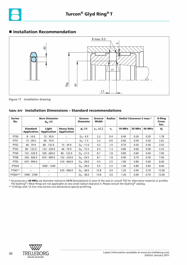
Installation Recommendation
R max. 0.3
L1
r1
S
d2
DN
d1
Figure 17 Installation drawing
Table XIV Installation Dimensions – Standard recommendations
Series-No.
Bore Diameter DN H9
Groove Diameter
Groove Width
Radius Radial Clearance S max.* O-Ring Cross-Sec.
Standard Application
Light Application
Heavy Duty Application
d1 h9 L1 +0.2 r1 10 MPa 20 MPa 40 MPa d2
PT00 8 - 14.9 15 - 39.9 -- DN - 4.9 2.2 0.4 0.40 0.30 0.20 1.78
PT01 15 - 39.9 40 - 79.9 -- DN - 7.5 3.2 0.6 0.60 0.50 0.30 2.62
PT02 40 - 79.9 80 - 132.9 15 - 39.9 DN - 11.0 4.2 1.0 0.70 0.50 0.30 3.53
PT03 80 - 132.9 133 - 329.9 40 - 79.9 DN - 15.5 6.3 1.3 0.80 0.60 0.40 5.33
PT04 133 - 329.9 330 - 669.9 80 - 132.9 DN - 21.0 8.1 1.8 0.80 0.60 0.40 7.00
PT08 330 - 669.9 670 - 999.9 133 - 329.9 DN - 24.5 8.1 1.8 0.90 0.70 0.50 7.00
PT05 670 - 999.9 -- 310 - 669.9 DN - 28.0 9.5 2.5 1.00 0.80 0.60 8.40
PT05X -- 1000 - 1200 -- DN - 28.0 9.5 2.5 1.00 0.80 0.60 8.40
PT06** -- -- 670 - 999.9 DN - 38.0 13.8 3.0 1.20 0.90 0.70 12.00
PT06X** 1000 - 2700 -- -- DN - 38.0 13.8 3.0 1.20 0.90 0.70 12.00
* At pressures > 40 MPa use diameter tolerance H8/f8 (bore/piston) in area of the seal or consult TSS for alternative material or profiles.TSS Slydring® / Wear Rings are not applicable at very small radical clearance S. Please consult the Slydring® catalog.
** O-Rings with 12 mm cross section are delivered as special profilring.
31Latest information available at www.tss.trelleborg.comEdition January 2011
Turcon® Glyd Ring® T
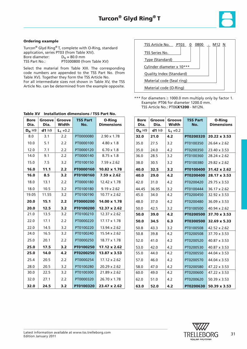
Ordering example
Turcon® Glyd Ring® T, complete with O-Ring, standard application, series PT03 (from Table XIV).Bore diameter: DN = 80.0 mmTSS Part No.: PT0300800 (from Table XV)
Select the material from Table XIII. The corresponding code numbers are appended to the TSS Part No. (from Table XV). Together they form the TSS Article No.For all intermediate sizes not shown in Table XV, the TSS Article No. can be determined from the example opposite.
Material code (Seal ring)
TSS Series No.
TSS Article No. M120800 N
Material code (O-Ring)
Cylinder diameter x 10***
PT03
Quality Index (Standard)
-
Type (Standard)
0
*** For diameters 1000.0 mm multiply only by factor 1.Example: PT06 for diameter 1200.0 mm. TSS Article No.: PT06X1200 - M12N.
Bore Dia.
Groove Dia.
Groove Width
TSS Part No.
O-Ring Dimensions
DN H9 d1 h9 L1 +0.2
8.0
10.0
12.0
3.1
5.1
7.1
2.2
2.2
2.2
PT0000080
PT0000100
PT0000120
2.90 x 1.78
4.80 x 1.8
6.70 x 1.8
14.0
15.0
16.0
9.1
7.5
11.1
2.2
3.2
2.2
PT0000140
PT0100150
PT0000160
8.75 x 1.8
7.59 x 2.62
10.82 x 1.78
16.0
18.0
18.0
8.5
13.1
10.5
3.2
2.2
3.2
PT0100160
PT0000180
PT0100180
7.59 x 2.62
12.42 x 1.78
9.19 x 2.62
19.05
20.0
20.0
11.55
15.1
12.5
3.2
2.2
3.2
PT0100190
PT0000200
PT0100200
10.77 x 2.62
14.00 x 1.78
12.37 x 2.62
21.0
22.0
22.0
13.5
17.1
14.5
3.2
2.2
3.2
PT0100210
PT0000220
PT0100220
12.37 x 2.62
17.17 x 1.78
13.94 x 2.62
24.0
25.0
25.0
16.5
20.1
17.5
3.2
2.2
3.2
PT0100240
PT0000250
PT0100250
15.54 x 2.62
18.77 x 1.78
17.12 x 2.62
25.0
25.4
28.0
14.0
20.5
20.5
4.2
2.2
3.2
PT0200250
PT0000254
PT0100280
13.87 x 3.53
17.12 x 2.62
20.29 x 2.62
30.0
32.0
32.0
22.5
27.1
24.5
3.2
2.2
3.2
PT0100300
PT0000320
PT0100320
21.89 x 2.62
26.70 x 1.78
23.47 x 2.62
Bore Dia.
Groove Dia.
Groove Width
TSS Part No.
O-Ring Dimensions
DN H9 d1 h9 L1 +0.2
32.0
35.0
35.0
21.0
27.5
24.0
4.2
3.2
4.2
PT0200320
PT0100350
PT0200350
20.22 x 3.53
26.64 x 2.62
23.40 x 3.53
36.0
38.0
40.0
28.5
30.5
32.5
3.2
3.2
3.2
PT0100360
PT0100380
PT0100400
28.24 x 2.62
29.82 x 2.62
31.42 x 2.62
40.0
42.0
44.45
29.0
31.0
36.95
4.2
4.2
3.2
PT0200400
PT0200420
PT0100444
28.17 x 3.53
29.75 x 3.53
36.17 x 2.62
45.0
48.0
50.0
34.0
37.0
42.5
4.2
4.2
3.2
PT0200450
PT0200480
PT0100500
32.92 x 3.53
36.09 x 3.53
40.94 x 2.62
50.0
50.0
50.8
39.0
34.5
43.3
4.2
6.3
3.2
PT0200500
PT0300500
PT0100508
37.70 x 3.53
32.69 x 5.33
42.52 x 2.62
50.8
52.0
53.0
39.8
41.0
42.0
4.2
4.2
4.2
PT0200508
PT0200520
PT0200530
37.70 x 3.53
40.87 x 3.53
40.87 x 3.53
55.0
57.0
58.0
44.0
46.0
47.0
4.2
4.2
4.2
PT0200550
PT0200570
PT0200580
44.04 x 3.53
44.04 x 3.53
47.22 x 3.53
60.0
62.0
63.0
49.0
51.0
52.0
4.2
4.2
4.2
PT0200600
PT0200620
PT0200630
47.22 x 3.53
50.39 x 3.53
50.39 x 3.53
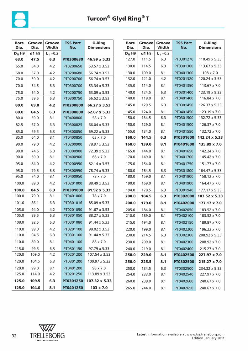
Table XV Installation dimensions / TSS Part No.
32 Latest information available at www.tss.trelleborg.comEdition January 2011
Turcon® Glyd Ring® T
Bore Dia.
Groove Dia.
Groove Width
TSS Part No.
O-Ring Dimensions
DN H9 d1 h9 L1 +0.2
63.0
65.0
68.0
47.5
54.0
57.0
6.3
4.2
4.2
PT0300630
PT0200650
PT0200680
46.99 x 5.33
53.57 x 3.53
56.74 x 3.53
70.0
70.0
75.0
59.0
54.5
64.0
4.2
6.3
4.2
PT0200700
PT0300700
PT0200750
56.74 x 3.53
53.34 x 5.33
63.09 x 3.53
75.0
80.0
80.0
59.5
69.0
64.5
6.3
4.2
6.3
PT0300750
PT0200800
PT0300800
56.52 x 3.53
66.27 x 3.53
62.87 x 5.33
80.0
82.5
85.0
59.0
67.0
69.5
8.1
6.3
6.3
PT0400800
PT0300825
PT0300850
58 x 7.0
66.04 x 5.33
69.22 x 5.33
85.0
90.0
90.0
64.0
79.0
74.5
8.1
4.2
6.3
PT0400850
PT0200900
PT0300900
63 x 7.0
78.97 x 3.53
72.39 x 5.33
90.0
95.0
95.0
69.0
84.0
79.5
8.1
4.2
6.3
PT0400900
PT0200950
PT0300950
68 x 7.0
82.14 x 3.53
78.74 x 5.33
95.0
100.0
100.0
74.0
89.0
84.5
8.1
4.2
6.3
PT0400950
PT0201000
PT0301000
73 x 7.0
88.49 x 3.53
81.92 x 5.33
100.0
101.6
105.0
79.0
86.1
94.0
8.1
6.3
4.2
PT0401000
PT0301016
PT0201050
78 x 7.0
85.09 x 5.33
91.67 x 3.53
105.0
108.0
110.0
89.5
92.5
99.0
6.3
6.3
4.2
PT0301050
PT0301080
PT0201100
88.27 x 5.33
91.44 x 5.33
98.02 x 3.53
110.0
110.0
115.0
94.5
89.0
99.5
6.3
8.1
6.3
PT0301100
PT0401100
PT0301150
91.44 x 5.33
88 x 7.0
97.79 x 5.33
120.0
120.0
120.0
109.0
104.5
99.0
4.2
6.3
8.1
PT0201200
PT0301200
PT0401200
107.54 x 3.53
100.97 x 5.33
98 x 7.0
125.0
125.0
125.0
114.0
109.5
104.0
4.2
6.3
8.1
PT0201250
PT0301250
PT0401250
113.89 x 3.53
107.32 x 5.33
103 x 7.0
Bore Dia.
Groove Dia.
Groove Width
TSS Part No.
O-Ring Dimensions
DN H9 d1 h9 L1 +0.2
127.0
130.0
130.0
111.5
114.5
109.0
6.3
6.3
8.1
PT0301270
PT0301300
PT0401300
110.49 x 5.33
113.67 x 5.33
108 x 7.0
132.0
135.0
140.0
121.0
114.0
124.5
4.2
8.1
6.3
PT0201320
PT0401350
PT0301400
120.24 x 3.53
113.67 x 7.0
123.19 x 5.33
140.0
145.0
145.0
119.0
129.5
124.0
8.1
6.3
8.1
PT0401400
PT0301450
PT0401450
116.84 x 7.0
126.37 x 5.33
123.19 x 7.0
150.0
150.0
155.0
134.5
129.0
134.0
6.3
8.1
8.1
PT0301500
PT0401500
PT0401550
132.72 x 5.33
126.37 x 7.0
132.72 x 7.0
160.0
160.0
165.0
144.5
139.0
144.0
6.3
8.1
8.1
PT0301600
PT0401600
PT0401650
142.24 x 5.33
135.89 x 7.0
142.24 x 7.0
170.0
175.0
180.0
149.0
154.0
164.5
8.1
8.1
6.3
PT0401700
PT0401750
PT0301800
145.42 x 7.0
151.77 x 7.0
164.47 x 5.33
180.0
190.0
194.0
159.0
169.0
178.5
8.1
8.1
6.3
PT0401800
PT0401900
PT0301940
158.12 x 7.0
164.47 x 7.0
177.17 x 5.33
200.0
200.0
205.0
184.5
179.0
184.0
6.3
8.1
8.1
PT0302000
PT0402000
PT0402050
183.52 x 5.33
177.17 x 7.0
183.52 x 7.0
210.0
215.0
220.0
189.0
194.0
199.0
8.1
8.1
8.1
PT0402100
PT0402150
PT0402200
183.52 x 7.0
189.87 x 7.0
196.22 x 7.0
230.0
230.0
240.0
214.5
209.0
219.0
6.3
8.1
8.1
PT0302300
PT0402300
PT0402400
208.92 x 5.33
208.92 x 7.0
215.27 x 7.0
250.0
250.0
250.0
229.0
225.5
134.5
8.1
8.1
6.3
PT0402500
PT0802500
PT0302500
227.97 x 7.0
215.27 x 7.0
234.32 x 5.33
254.0
260.0
265.0
233.0
239.0
244.0
8.1
8.1
8.1
PT0402540
PT0402600
PT0402650
227.97 x 7.0
240.67 x 7.0
240.67 x 7.0
33Latest information available at www.tss.trelleborg.comEdition January 2011
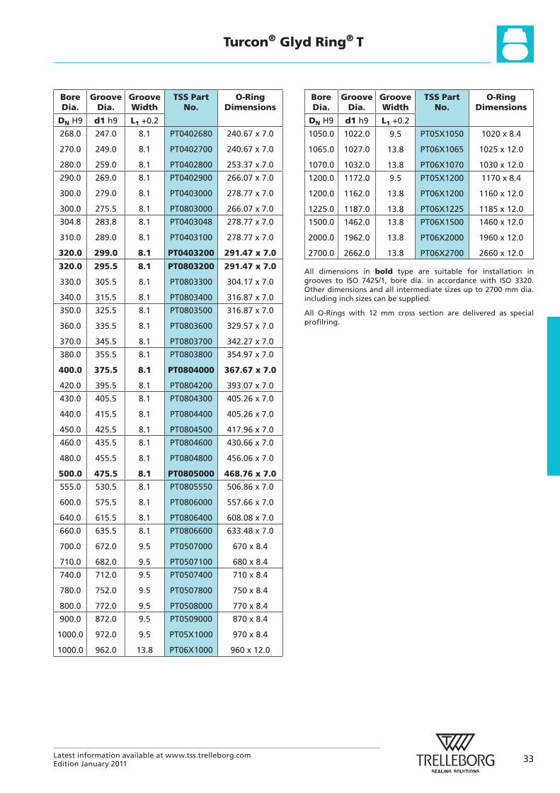
Turcon® Glyd Ring® T
Bore Dia.
Groove Dia.
Groove Width
TSS Part No.
O-Ring Dimensions
DN H9 d1 h9 L1 +0.2
268.0
270.0
280.0
247.0
249.0
259.0
8.1
8.1
8.1
PT0402680
PT0402700
PT0402800
240.67 x 7.0
240.67 x 7.0
253.37 x 7.0
290.0
300.0
300.0
269.0
279.0
275.5
8.1
8.1
8.1
PT0402900
PT0403000
PT0803000
266.07 x 7.0
278.77 x 7.0
266.07 x 7.0
304.8
310.0
320.0
283.8
289.0
299.0
8.1
8.1
8.1
PT0403048
PT0403100
PT0403200
278.77 x 7.0
278.77 x 7.0
291.47 x 7.0
320.0
330.0
340.0
295.5
305.5
315.5
8.1
8.1
8.1
PT0803200
PT0803300
PT0803400
291.47 x 7.0
304.17 x 7.0
316.87 x 7.0
350.0
360.0
370.0
325.5
335.5
345.5
8.1
8.1
8.1
PT0803500
PT0803600
PT0803700
316.87 x 7.0
329.57 x 7.0
342.27 x 7.0
380.0
400.0
420.0
355.5
375.5
395.5
8.1
8.1
8.1
PT0803800
PT0804000
PT0804200
354.97 x 7.0
367.67 x 7.0
393.07 x 7.0
430.0
440.0
450.0
405.5
415.5
425.5
8.1
8.1
8.1
PT0804300
PT0804400
PT0804500
405.26 x 7.0
405.26 x 7.0
417.96 x 7.0
460.0
480.0
500.0
435.5
455.5
475.5
8.1
8.1
8.1
PT0804600
PT0804800
PT0805000
430.66 x 7.0
456.06 x 7.0
468.76 x 7.0
555.0
600.0
640.0
530.5
575.5
615.5
8.1
8.1
8.1
PT0805550
PT0806000
PT0806400
506.86 x 7.0
557.66 x 7.0
608.08 x 7.0
660.0
700.0
710.0
635.5
672.0
682.0
8.1
9.5
9.5
PT0806600
PT0507000
PT0507100
633.48 x 7.0
670 x 8.4
680 x 8.4
740.0
780.0
800.0
712.0
752.0
772.0
9.5
9.5
9.5
PT0507400
PT0507800
PT0508000
710 x 8.4
750 x 8.4
770 x 8.4
900.0
1000.0
1000.0
872.0
972.0
962.0
9.5
9.5
13.8
PT0509000
PT05X1000
PT06X1000
870 x 8.4
970 x 8.4
960 x 12.0
Bore Dia.
Groove Dia.
Groove Width
TSS Part No.
O-Ring Dimensions
DN H9 d1 h9 L1 +0.2
1050.0
1065.0
1070.0
1022.0
1027.0
1032.0
9.5
13.8
13.8
PT05X1050
PT06X1065
PT06X1070
1020 x 8.4
1025 x 12.0
1030 x 12.0
1200.0
1200.0
1225.0
1172.0
1162.0
1187.0
9.5
13.8
13.8
PT05X1200
PT06X1200
PT06X1225
1170 x 8.4
1160 x 12.0
1185 x 12.0
1500.0
2000.0
2700.0
1462.0
1962.0
2662.0
13.8
13.8
13.8
PT06X1500
PT06X2000
PT06X2700
1460 x 12.0
1960 x 12.0
2660 x 12.0
All dimensions in bold type are suitable for installation in grooves to ISO 7425/1, bore dia. in accordance with ISO 3320. Other dimensions and all intermediate sizes up to 2700 mm dia. including inch sizes can be supplied.
All O-Rings with 12 mm cross section are delivered as special profilring.