Embed Size (px)
Citation preview
. . .,TWHUI.Q.ALMEMOEAliDUMS .. .. .. . . .
NATIONAL ADVISORY COMMITTIE FOE AEROEhUTICS
UJ4 ------,-------/
%d
NO. 879:%
L..;,,rI,..
STATIC LO?U31TUI)IHAL STABILITY Al!?D
101?(31TUDINAE COHTROL Ol? AUTOGIRO ROTORS
By M. Schrenk
Luftfahrtforschum
f’ Vol. 15, Ho. 6, June 61 1938Terlag von E. Oldenb,ourg, liiinchen~d Berlin
w-+ -t,.... . . . , . . . . . ..-1 ... . . . . . . ,,. ,-,. .
WashingtonOctober 1938
.-
9
1,%, 1.!,;
‘-7,-I ,3.,.1*
,.’+
..— .. I
.-%.J
MATIOI?AL ADVISORY +OiMITTEE
v.’
FOR AERONAUTICS
TECHNICAL MEMORANDUM
-.. ! . . —.
EO. 879
.,.. . -., . ...- -
STATIC LOMGITUDII?AL STABILITY AND
LOlU31TUDIl?AL CONTROL OF AUTOGIRO ROTORS*
By M. Schrenk
SUMURY
The present rsport discusses three different systemsof elevator control and their effects on the stability andmaneuverability of autogiros: (a) ailerons and elevatore(standard); (b) blade control (la Clerva); (c) gravitycontrol (new).
The control senOiti.vitydv~’
which is dependent to a
great degree” on the speed in s~’stem (a), becomes substan-tially more uniform in eystem (b), and practically constanttnrough the whole rango from zero to maximum speed in eys--tem (c). At the same time, the highest restoring momentsattainable at pull-up become coneintontly smaller. The im-portant charaoteristlcs of blade control and gravity con-trol are:
1) Flattening out from a high-speed dive Is smootherand with little etretas;
2) The airplane can be landed with very small controldeflection;
3) Steering 1s not too sensitive at high speeds;
4) The maximum permieslble speed can be easily and~afely limited by control movements, a factwhich constitutes a special safeguard for anautogiro rotor having a prescribed maximum co-efficient of advance.
The control-force balance can be readily achieved byproper design of the rotor head with its suspension. The
*llStatlsche L&ngsstabllit&t und Ht!hensteuerung von Trag-schrauben .W Zuftfahrtforechung, vol. 15, no. 6, June 6,1938, pp. 283-289.

&
w’ .2 M.A. C.A. Technical M@nQ#an&~”Ho. 879
control forceta (to be kept ntoderate)””with blade controland gravity control also “change linearly with the speed.The shifting of the equilibrium condition or balance ofcenter of gravity dfaplacementm, attainable by suitablestructural design of the rotor head assembly, affectsneither stability nor control-force variation.
I. INTRODUCTION
1. Aerodynamic Principles
. .1) The calculation of the rotor-blade moments is ap-
parent from the report entitled ‘lThe Aerodynamic priIICipleS
of the Autogiro Rotori’ (reference 1). In It the flow lossesat the rotor had been divided Into three sectl-ens, charac-t~rized by the three coefficients ‘i‘ cd, and Cu. It was
proved that the resultant rotor force at vanishing coeffi-cient of advance must, for reasons of s~mmetry, lie in theaxis of rotation and that the asymmetrical Inflow df therotor of finite coefficient of advance is followed by abackward inclination of the resultant in relatlon to theaxis of rotation.
In figure 1, accordingly, the total force (S) of the‘irotor of vanishin~ coefficient of advance” is located Inthe axis of rotation (dash-dots), the actual resultant S
“is further inclined by Cu; Cu is the coefficient of the
nonuniformity loss. The result is the plot of figure 2,upon which the entire subsequent calculation of the rotormouents is based. The end points of the rotor force vec-tors (coefficient cS) are approximately located (as isreadily proved) on a parabola of the second order.
Admittedly this Is applicable for the present only tothe simplified picture of an autoglro rotor with very heavyblades, where the bla~es, sufficiently approximated, may bevisualized as rotating In one plane. The 5° to 9° cone an-gles for the conventional blade designs causo a certainforward shift of the air forces, especially at small anglesof attack. It further Is assumed that the blade hinges liein the axis of rotation. But In reali%y tney are always acertain distance away from it for constructional reaeons.
...- ----- .. . ,
Both affects enhance the stabilizing actions of theair forces on the rotor moment, but, being little amenableto mathematical treatment, will be disregarded here. The
:.
M.A. C.A. Techni-cal Memorandum I?o..879 3
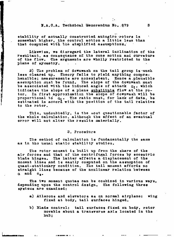
.,.stability of actually constructed autoglro -rotors Is ‘somewhat higher , the control aotion a little lefaa thanthat computed with %hb simplified assumpttoria.” “
Llkewlse, we disregard the lateral inclination of theresultant, as consequence ofi the cone motion and curvatureof the flow. The arguments are wholly restricted to theplane of symmetry. . .
2) The problem of downwaeh on the tail group is”mueh1000 cleared up. Theory fall~ to yield anything compr.e-henslble; measurements aro nonexistent. Hence a.plausdbleassumption must be found. The slope of the downwash mustbe associated with the iaduce~ angle of attack ci, whichindicateq the slope of a plane substitute flow at the ro-tor. In first approximation the slope of downwash wI1l beProportional to a .
iThe ratio must, for lack of data, be
estimated In accor with the position of the tall relatlveto the rotor.
This, undoubtedly, Is the i~ost questionable factor ofthe whole calculation, although the effect of an eventualerror will not alter the results materially.
2. Frocedure
The method of calculation is fundamentally the sameas in tho usual static stability studies,
The rotor mcment is built up frcu the share of theair forces and that of the centrifugal forces by eccentricblade hinges. The latter effects a displacement of themoment lines and Is easily computed on the assu~tion ofquasi-statfon’ary conditicn. Tile tail mouent affords nostraight lines because of the nonlinear relation betweena and Cs.
The two mcment quotas can be combined in various ways,depending upon the control design. The following threesysteus are oxamlned:
a) Ailerons and elevators as op normal airplane: wingfixed at body, tail surfaces hinged.
b) Blade control: tail surfaces fixed on body, rotormovable about a transverse axis located in thehub ;
. .-.. —-
I
4 19.A. C.A. Technical Memormdum Ho. 879
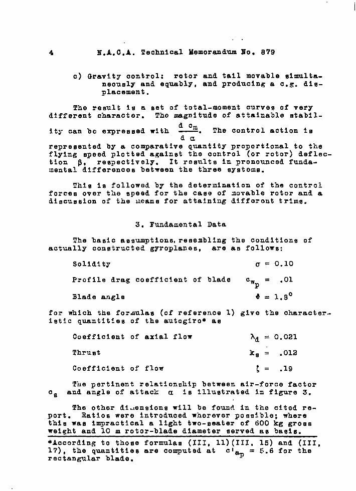
c) Gravity control: rotor and tail movable simulta.neously and equably, and producing a e.g. dis-placement.
The result Is a set of total-moment curves of verydifferent character. Tho magnitude of attainable stabll-
d Cmity can bc expressed with —. The control action is
darepresented by a comparative quantity proportional to theflying speed plotted against the control (or rotor) deflec-tion P~ res~ectlvely. It results in pronounced funda-mental differences between the three systems.
This is followod by the determination of the controlforces over the speed for the case of novablo rotor and adiscussion of the means for attaining different trims.
3. Fundamental Data
The basic assumptions, resembling the conditions ofactually constructed gyroplanes, are as follows:
Solidity (J= 0.10
Profile drag coefficient of blade Cw = .01P
Blade angle d = 1.9°
for which the formzlas (of reference 1) give the character-istic quantities of the autogiro* as
Coefficient of axial flow Ad = 0.021
Thrust kg = .012
Coefficient of flow t = .19
The pertinent relationship between air-force factor
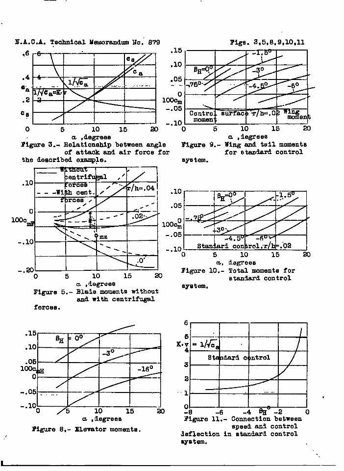
Cs and angle of attack a is Illustrated in figure 3.
The other di.mnsiocs will be found in the cited re-port. Ratios were introduced wherever possible; wherethis was impractical a light two-seater of 600 kg grossweight and 10 m rotor-blade diameter served as basis.
*According to those formulas (III, 11)(111, 15) and (III,17), the quantities are computed at
c’%= 5.6 for the
rectangular blade.
I?.A. C.A. Techm&Gal Homorandum Mo. 879 5. ....”. . . .
4. Symbols
Other thazi”t-hb”eyrnbiilsgiven in the cited report (ref -erenae 1) the following are aleo’ umed:
r e.g. position back
h height of rotor position
‘H ta~il surface lever arm
aj b, c, d, e, f dlmenelonn of control according tofigure 17
m mass of rotor blade per unit length
P proportionality factor for downwashslope
$ angle of the control (~Hs PY)
P control-stick force
II. Partial Moments
1. Rotor Moment, Hinges In Axis of Rotation
With tho notation of figure 4 (where the backwardposition r of the center of gravity Is negative) the air-forco moment s is:
Ida = - S(h Cu + r)
whl ch , reduced to dynamic pressure, rotor area, and diam-eter, gives tho moment factor
MaCma = =. Ca ;(~+;)
P/2 v= F D
According to the report 345 (reference 1), cm can be ex-
pressed In the fundamental quantities of the autogiro.
With K = ~ and cos a = 1 (reference 1, formula VI, 9)8
for the lancet-shaped blade) it is: .
.,.. - ., -m-. . —.

I?.A. C.A. Technical Mern.orar@um Ilo. 879
Hence:
;(;/’+:)cm = -cB -a
(1)
A general examination of figure 4 discloses that,with suitably chosen r, the rotor moments afford astable equilibrium. The backward-position limit IS r =O (e.g. in axis of rotation), whereby the rotor moment isbalanced in vertical ascent; as the e.g. Is shifted for-ward (r negative) the rate of the aoffientequilibrium in-creases.”
The dotted lines (fig. 5) confirm this and indicatethat fairly small e.g. displacements sufflco to producepronounced changes in the angle of attack of the balance.(To avoid deci-1 fractions, the mo:~ent coefficients aremultiplied by lCO.)
2. Rotor lioment, Hin~os Eccentric
As already stated in the introduction, the effect ofthe blado-hlnfie distance from the axis of rotation is tobe examined only as regards the moments.of tho centrifugalforces due to the flapping motion.
. .
Figure 5 illustrates a rotor head with two hingesin the plane of symmetry. Uader the initial assuinption ofthe blades rotating In one plane, the centrifugal forcosZ applied at the hinge are Fara$lel and Inclined thrQughflappln:~ angle PLS’ the amouat of-which can be approxi-
1mated ~reference 1, IV, 10; factor is made =
. ....(
1- C2 )
3/2) at:
4“$1 = @ + ~tt) ~ (2)
HOW, an autogiro usually has three rather than twoblades, and consequentl~ two blade forces inclined %0°
towaad the plahd of symme~ry instead. of the ~ne shown.. ~h~ minor fluctuations In tho resultant centrifugal forces,,--.occurring during rothi~o~”vftih’’il~-tirnds.-fhe ffequency.ofthe revolution speed, In.tune plaqe.qf qyemmetr7, can be fg- .nored here. .:.
Then, with Q as.t.he blade ~EIS per uait length, wehave: .. ..
Mz = -2Z a PI .
f
Cswhence, with equation (2) and A =
~
L(*= -3amva @d+; d)&a
and
Re@arding tbie deviation, it should be observed thatt>e flapping angle P, in equation (3) Ie dependent on A,Cn reepectlvely. This formula therefore gives the addi -
tlonal moment due to the centrifugal force for the steadyetage, that ,is, the dynamic pressure.of horizontal flightfor the related fllght condition. In reality the dynamicpressure doos not change at all In firet approximationduring angle of attack fluctuations; the moment of the cen-trifugal force, viewed from the moinentary equilibrium con-
. dition, varioe somewhat differently. To allow for this,it would be necessary to drav a second curve of the addi-tional moments produced during o.ecillattons from everypoint of the stationary curve. However, since lt usuallyinvolves only small oscillations; this task is unnecessary,particularly within the scope of the present, strictlystatic analysis. ., .
B’or the mathemat~cal intbrpr~tation of,”eq~.tion (3),it should be borne in”ruind that m, the blade daea per
., i ,., . .#. .,.
.—
8 N. A. C,A. YechnicaJ. Memorandum Mo,. 879
length, should be proportional to the” disk area T, when
cmz became unaffected by the scale. Mow, ~ Is,withoutE
a doubt, not” constant,* but bound to the scale; that 1s,definite numerical conditions must be used as a basis.
In conformity with the conditions on a light two-seat-er, assume
D =lOm F = 78.5 ma
a = 80 mm mg = 2 kg/m
The theoretical values are included In figure 5. Theyapply with slight changes to any other not abnormally dif-ferent dimension.
3. Tail tioment
The angle of attack of the tail is according to theintroduction and to figure 7:
aH(cg) = a(ca) - p ai(cg) + pH (4)
The proportional factor p, which indicates the amount ofslope of the flow at the tail as a result of Its curvatureover that at the rotor axis, Is probably not altogetherconstant. But , lacking sore exact information, a linearrelationship Is assumed for which lH/D = 0.5, we put
. .P = 1.2
The tall with the deflection. pH is assumed to be undivid--ed, in order to simplify the analysis.
In formula (4) ai(cg) IS linear, while cf(cg) con-
tains a parabolic shqre (angle of.f}ow ~, “reference 1).
●To ~llugtrate, if, by enlargement of the rotor the coneangle is to rehain constant, the thrust load per un3t
length of blade increases at equalc%
and ; (u=
const.) linearly with the diameter i), that 1s, the samemust hold for radial loading. But. thi.s depends under thecited conditions, only on. m~ which in consequence %tselfincreases linearly with Q.
I
9
..
N.A,C.A. Techntoal Memorandum Mo. 879 9
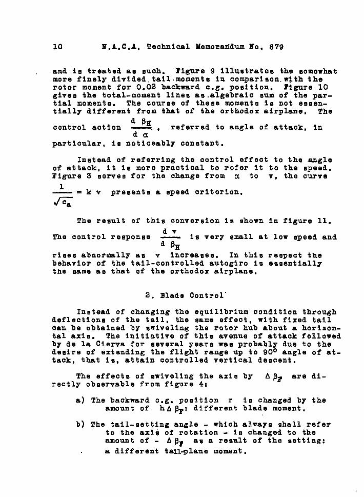
In consequence, UH(CS) -will no longer be linear, that is,
.the.,tall-moue.n.t.=l~p.e-~g,not et.:_qlght.., .. ...-.. ,-..---...
Its coeffiolent 1s:
cmH = aH Cl 35%F D (5) .
..
c~a ,H
the slope of the tail lift above its angle of at-
taak, Is for an aepeot ratio of A = 3 (In degree):
0.055c1 = 0.06°aK = C.565 + l/JS . .
Since the rotor moiuent with suitably chosen c.g.-posi.tionitmelf is stable, the choice of tall dimensions is merely
. contingent upon the desired control range and the neces-sary daqing capacit~ against onclllatlons...
With the choson proportionality factors
equation (5) finally gives
100 cmH = 100 aH X 0.06
and 2=*
x 0.01 x 0.5 = 0.03 a~(cs)
When computing ~H according to equation (4), a(cs)
should be t.aken.from figure 3, ai(c ) from figure 18 ofReport Ho. 345 (reference l)., The o~tained noment coeffi-cients are shown in figure 8. The llnes for different el~vator deflections ~H differ from one another only by a
constant difference In caH.
III. TOTAL MOMEJRFS, STATIC STABILITY
1. Aileron and Elevator Control
The firHt caee.iw that of the normal airplane control
10 I?.A. C.A. Technical Memozazidum Ho. 879
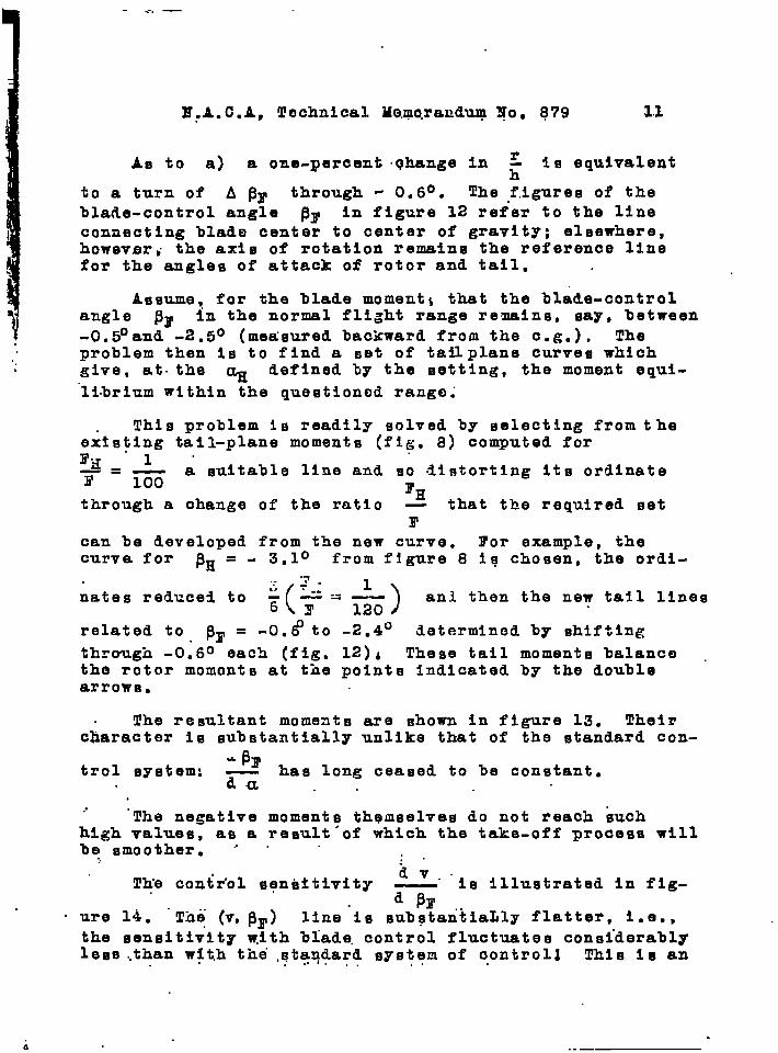
and ia treated a~ such. S’igure 9 illustrates the eomowhatmore finely divided. tail.moments In comparison.with therotor moment for 0.02 backward e.g. position. lFlgure 10gives the total-moment lines as.algebralc sum of the par-tial moments. The course of these moments is not essen-tially different from that of the orthodox airplane. The
d ~Hcontrol action —. , referred to angle of attack, In
daparticular, IS noticeably constant.
Instead of referring the control effect to the agleof attack, it is more practical to refer it to the speed.Figure 3 serves for the change from a to v, the curve
— = k v presents a speed criterion.
k
The result of this conversion is shown in figure 11.
dvThe control response — is very small at low speed and
d ~Hrises abnormally as v increases. In this respect thebehavior of the tail-controlled autogiro Is essentiallythe same as that of the orthodox airplane.
2. Blade Control-
Inetead of changing the equilibrium condition throughdeflections of the tail, the same effect, with fixed tailcan be obtained by swiveling the rotor hub about a horizon-tal axis. The initiative of this avenue of attack followedby de la Clerva for several years waa probably due to thedesire of extending the flight range up to 90° angletack, that is, attain controlled vertical desoent.
The effects of Bwiveling ths axis by A~r arerectly observable from figure 4:
a) The backward e.g. position r is changed byamount of hA~F: different blade moment.
of at-
di-
the
b) The tail-setting angle - which always shall referto the axi~ of rotation - Is changed to theamount of - A P~ as a result of the setting:
a different tail~lano moment.
. . —
1
E:A. C.AP !J!ochnical Me.rno.rauduqgo. 879 3.1
AO to a) a one-percent .t$hange In r 10 equivalentz
to a turn of ~ Pr through - 0.6°. The f.iguree of the
blade-control angle Pr in figure 12 refer to the l~neconnecting blade center to center of gravity; eleewhere,howevsrti the axiB of rotation remains the reference linefor the angles of attack of rotor and tail. .
~
Assume! for the blade momentt that the bl&le-controlangle SF in the normal flight range remains, say, between-0.5°and -2.5° (measured backward from the e.g.). Theproblem then is to find a set of tailplane curves which,,give, at. the ~ defined by the setting, the moment equl-
“li.brlum within the questioned range;
This problem is readily solved by selecting from theextsting tail-plane moments (fig. 8) computed forlr~”l”—=E
a suitable line and so distorting Its ordinateG
through a ohange of the ratio*H— that the required setr
can be developed from the new curve. l’or example, thecurva for ~H = - 3m10 from figure 8 iq chosen, the ordi-
.~...
(-7 -h 1
nates reduce~ to:y=~ )
anl then the new tall lines
related to Py = -0.#to -2.4° determlnod by shifting
through -O~60 each (fig. 12)A These tail moments balance .the rotor momonts at the points indicated by the doublearrows.
The resultant moments are shown in figure 13. Theircharacter is substantially unlike that of the standard con-
- Prtrol system: hag long cea~ed to be constant.
G..
..“The negative moments themselves do not reach buch
high values, as a result-of which the take-off process willbe, smoother. ‘ . “ ;.
T~e contr’ol sensitivitydv..— Is illustrated in fig-d PE
o ure 14. “The (v,~F) line-is subqtaritiaLly flatter, i.e.,the sensitivity with biade. control fluctuates considerablylese..tilan with thei ,qtaq~ard system of c.ontrol~ This Is an..
..—
.
12 lT.A.C.Ai Techhical .Mernoraddum lZb..J379
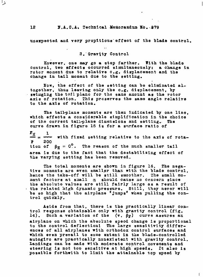
unexpected and very propitious” effect of the blade oontrol.
. .
3m” Qravtty Control
However, one may go a step farther. With the bladecontrol, two effects occurred simultaneously: a change inrotor moment due to relative e.g. displacement and thechange in tail moment due to the setting.
Now, the effect of the setting can be eliminated al-together, thus leaving only the e.g. displacement, byswinging the t~~l piano for the same amount as the rotoraxis of rotation. This preserves the same angle relativeto the axis of rotation.
The tall~lane moments are then indicated by one line,which effects a considerable simplification in the choiceof the correct tall-lane dimensions and setting.. Thecurve drawn In figure 15 is for a surface ratio of
‘H 1—=— with fixed setting relative to the axis of rota-B’ 200tlon of ~H=Oo* The reason of the much smaller tail
area is due to the fact that the destabilizing effect ofthe varying setting has been removed.
The total moments are shown in figure 16. The nega-tive moments are even smaller than with the blade control,hence the take-off will be still smoother. The small mo-ment factors at small u should cause ao ccncern sincethe absolute values are still fairly large as a result of
. the related high dynamic pressure. still, they never willbe so high that the airplane IIjumps’1 when pulling the con-trol quickly.
Aside from that, there is the practically linear con-trol response obtainable only with gravity control (fig.14) . Such a variation of the (v, ~F) curve assures an
airplane on which the absol-ate speed change is proportionalto the control deflection The largo sensitivity differ-ences of all airplanes with orthodox control surfaces andwhich even prevail to some extent in the blade-controlledautogiro are practically nonexistent with gravity control.Landings can be made with moderate control movements andsteering 1.snot too sensitive at high speeds. It also ispossible forthwith to limit the attainable top speed by
I
H.A..C..A. Tec~ical Memorandum Ho. 879 13
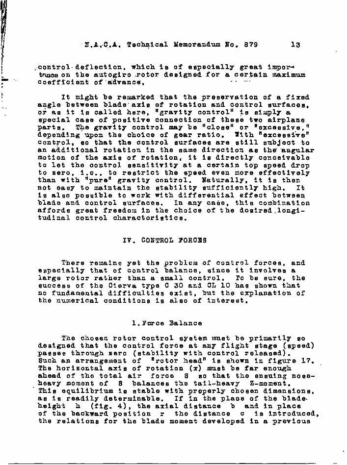
i’j ,.control.deflection, which is of especially great impor-. tnnce on the autogiro rotor designed for a certain maximum- ..P coefficient of ‘adWanca. .. ....r
iIt might be remarked that the preservation of a fixed
angle between blade” axis of rotation and control surfaces,.,or as it Is called here, “gravity control” is simply aspecial case of positive connection of these twc airplaneparts. T@e gravity control may be “close” or ‘Iexcessive,lldepending upon the choice of gear ratio. With ‘iexcessi-ve’fcontrol, 80 that the control surfacee are tatill subject toan additional rotation in the same direction as tha “angularmotion of the axis of rotation, it is directly conceivableto let the ccntrol sensitivity at a certain top speed dropto zero, i.e., to restric% the speed even more effectivelythan with llpureH gravity control. Naturally, it is thennot easy to maintain the stability sufficiently high. Itis also possible to work with differential effect betweenblade and control surfaces. In any caee, this combinationaffords great freedom in the choice cf the doslred.longi-tudlnal control charactoristlcs.
IV. CONTROL FORCES
There remains yet the problcm of control forces, andespecially that of control balance, since it involves alarge rotor rather than a small control. 10 be sure, thesuccess of the Clerva type C 30 aE~ ~~J 10 has shown thatno fundamental difficulties exist, but the oxplanatlon ofthe numerical conditions is also of Interest.
l.I’crce Balance
The chosen rotor control system must be primarily soLeslgned that the control force at any flight stage (speed)passes through zero (stability with control released).Such an arrangement of ‘rotor head” Is shown In figure 17.The horizontal axis of rotation (x) must be far enoughahead of the total air forc~ S so that the ensuing nose-heavy moment of S ~alances tho tail-heavy Z-moment.This equilibrium IS stable with properly chosen dimensions,as Is readily determinable. If in the place of the blade.height h (fig. 4), the axial distance b and in placeof the backward position r the distance c is Introduced,the relations for the blade moment developed in a provlous
—
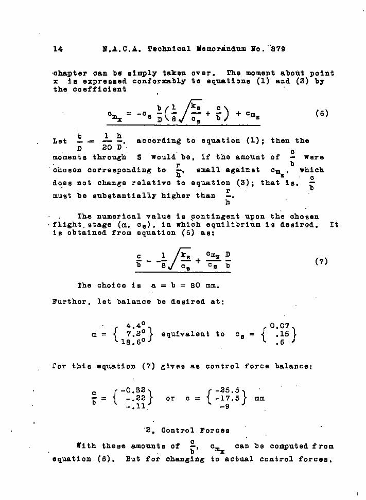
14 E.A. C.A. Technical Memorandum MO. -”879
chapter can bei simplY taken over. The moment about pointx Is expressed conformably to equations (1) and (3) bythe coefficient .
(6)
b lhLet --u= --, according to equation (l); then the
D 20D.
mo”ments through S would” be, if the amount of ~ wereb
“chosen oorreeponding to:’
small against cmz 0 which
does not change relative to equation (3); that is,” ~
must be substantially higher than ~.%.a
. . The numerical value is ~ontingent upon the chosen
.fllght. stage (a, Cfj), in which equilibrium Is desired. Itis obtained from equation (6) as:
c
f
1 Jfs cm= D-=--b 0
—+—-cs bcm
(7)
!Che choice is a = b = 80 mm.
Further, let balance be desired at:
a={:+!}equivalent to cs ={007}
:15● .6
for this equation (7) gives as control force balance:
‘2. Control Forces “
With these amounts of ~, cm can be computed fromx
equation (6). But for changing to actual control forces,
I

15
Ithe transmission ratio betyc.?n contrql. st.~ck and blade as~-1~ se-the “st!olrlength is needed?, ,:Supposq, the total de-
““fle.ctions are: “ ‘ ..... .
A~1=30 (f& 14), A $~t = 48° “
. .that ie, a 1:16 ratio bet~ieon blade and control stick.This gives by way of example . . :
\..
d = 320&n’j e ‘= 2omm “, “ “ “
/’ :.
:, Let the length of control Btick beI
f = 500 mm
Then”the control force becomes:
G“or , with q = —
lrc~.
e D cmxP = .-— G (8)
“d f C=
which for G = 600 kg find i)= 10 u flfially e.ffords
ciuxP = 750 —
Cs
The related numerical values are presented in figure 18.The point for v = O (vertical descent) Is computod fromthe ~lmple equllibri~ equati6n (fig. 17):
—
, ifx=cG
. .P
CsG = 0.075 c :
= Z“F
All potnts aro.locatod on E st.~lght l~n~ for a certainequilibrium stage (c = const.)”. A~gles and forces at thecontrol thus pass (at least with gravity control) to both. .....

I
16 ti.A.”C.A. Technical Memorandum Mo. 879
sid6q of the equilibrium speed, linearly with the speedchange. The conceivably most promiein~ longitudinal con-trol characteristics are the result. The forces remainwithin = kg, that is, easil~ applied.
.“
3.. Trim
A final problem Involves the change - with blade orgravity control - of the equilibrium position with controlreleased and the balancing of a displaceinent in the e.g.position.
1) The use of springs might be resorted to for influenc-ing the equilibrium position. But they have the undeslr.able quality of forming vibratory systems. But there isone almost “natural” solution which consists (fig. 19) Inmounting the pivot B adjustable in relation to the ele-vator lever C, so that thG distance of the axis of rota-tion from the elevator axis (c in fig. 17) can be changedat will. Since it Involves a space of a few mm only, thisshould be constructively easy (spindle with flexible shaft).Figure 18 presents the effect of the distance c on theequilibrium speed of our example.
2) The blade moment with wings fixed to the fuselage isvery eensitive to e.g. displacements (fig. 5). With mov-able wings and stable stress distribution the e.g. dis-placement for control released is, of course, without ef-fect on the blade moment, since it always assumes the sameangle of attack to the air stream. But with blade control,the position of the body affects the setting between finand blade, the fin receives an additional stress with theresult that tho stability is changed in unpredictable man-ner.
This is not the case with pure gravity control, be-cause the angle of setting is not affected by the positionof the fuselage. Still the changed position may have dis-agreeable consequences In practical service; the controlstick setting for a certain flight condition in particular,changes when the e.g. is displaced. This might be overcome,by ad$usting the push-rod lengtk between control and blade;but it 1S more logical to simply shift the blade by theamount of the e.g. change relative to the fuselage. Figure19 illustrates this with the carriage guide. between D andE.
Such a solution results In an airplane on which changes
H.A.C.A. Technical Memorandum No. 879 17
In equilibrium-dynamic pressure can be attained and cen-ter of gravity displacements can be balanced in a large
* measure, without. one- precautlo.n=ry-meamure--ln$luenclngthe other or changing the static longitudinal stabilityof the whole Bystem.
Translation by J. Vanier,National Advisory Committeefor Aeronautics.
1. Schrenk, Martin: Aerodynamic Principles of the DirectLifting Propeller. T.M. NO. 733, N.A.C.A. , 1934.
—- . .. . .
M.A.C.A. TechnicalMemorandumNo. 879 Figs. 1,2,4,6,7,17,18,19
If~,
4
a’
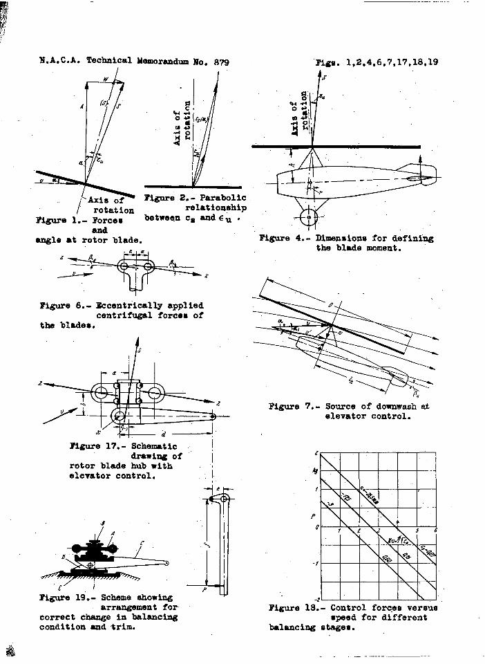
I rotationI?igure 1.- Forces
andangle ●t rotor blade.
E?igure2.- Parabolicrelationship
betweenc~ andcu .
Figure 6.- Eccentrically appliedcentrifugal forces of
the blades.
/$
z
x
Figure 17.- Schematic IdrawiuzOf i
rotor blade hub withelevator control.
-8
1
~igure 19.- Scheme showingarrangement for
correct change in balancingcondition and trim.
i
-+ ,
1\Pa
t /s
-x
.. . — - — -
“w’e’Figure4.- Dimensionsfor defining
the blademoment.
Figure 7.- Source of downwash atelevatorcontrol.
“REEEE‘LxKmEI
Figure 18.- Control forces versusspeed for different
balancing stages.
.- . . . . . ..—
.
I?.A.C.A. Teohnioal Memorandum No.”8?9
.6 .15
● 10
.05- ..
100:-.05
-.10
rigs. 3,5,8,9,10,11
-b7#jo’
mamen
o 5.-—
10 15 m 0 5a ,degreee
Figure 3.- Relationahlp between angle Ylgure 9.-of attaok and air force for
the deecribed example. ayatam.
s /entrifigal ,’
/—1.10 I
~orceO / “-- - -Wip > :/h=.041 .10cent. 0 I
fb rcea z i/ .
/ /“ .050 - -;. — —
-.10} I \ \ 1-“1 -1.
I1
10 15 20a ,degreeeWing and tail momentefor standard control
a ,flegreeeFigure 5.- Blade moments without
and with centrl~lforcee.
.15- /~ = 0> “
.10 e ‘
.0510W ~
o F T
-.05 . . .. . — 4
-.100 /5 10 15 20
a ,degreeO
Elgure 8,- Elevator moments..’
a,Figure 10.-
qwtem.
dagreee
Total moments foretandexd control
61I I 7 I 1
5 --K*~ = l/& .
I
Standard c mtrol3
2 /~
1 “ .-.--
:8-- I I I I-6 -4 %“ -2 0
Figure ll;- Connecti& betweenspeed an3 control
deflection In atandar~ controlOyetmm.

. . .
11.A.C.A. Technical Memcran3um Ho. 879 3igs. 12,13,14,15,16
.1
.1
;0 12.- Bla& and controleurface moments for
ontrol. The double arrowae the related lines anl the
100-g” f the corresponding mouent
1●
-9
-.1
a ,degrees
.10 —— I .1*%= -+.E0 -~,2° ‘T %?=-f”$”
.05 .10-2.4? -0.6°
c / - ‘&g—.—.
loo% 1— ./-0 05 –— 0‘-l .8° -1:20
-. 10 — -.05 - +% ~ ‘o 5 10 15 20 B;aie
IQ Uxlena - ‘- . -0.6°a ,degreee -. /
IWgure 13.- Total momentOfor 3ravity Oontrol illb~e controlii. r 1-. 100 5 10
l’i~e 15.-frees 15 ~
Bla%e’% control taurface
6 .‘momemts with Ilgravity controlii.
1 “10 ~=2. 4: J o #.!-l.205 .05 .—
100Q I4
-0.6~
3 -.05 Grav!ty contl’01 IK*v=l ~a
—.—0 5 10 15 20
2
Figure 16.-
.0 -1 -2 .3%0
I’lgure14.. Relation between epee~ and control3eflection for ‘iblafiecontroln an~
controln. The control sensitivity correepon3eelope of the tangent to the curve at the particularpoint, It 10 practically con~tant with ‘gravity centroln.
a ,degreeO
Total momenta with‘gravity controln,
ugravi~to the

,.-,—.——..,. —.,,.’ .—,. .
llllqlgggp~ \ ,. ~~ :’“~‘- “---‘“‘,,. ,,,’ ,, ,.
.,, . ,!
9
,.
.
I
,,
,.,,
,.”