Embed Size (px)
Citation preview
Underwater Active Oneshot Scan withStatic Wave Pattern and Bundle Adjustment
Hiroki Morinaga1, Hirohisa Baba1, Marco Visentini-Scarzanella1,Hiroshi Kawasaki1, Ryo Furukawa2, and Ryusuke Sagawa3
1 Kagoshima University, Japan{marco,kawasaki}@ibe.kagoshima-u.ac.jp
2 Hiroshima City University, [email protected]
3 National Institute of Advanced Industrial Science and Technology, [email protected]
Abstract. Structured Light Systems (SLS) are widely used for various purposes.Recently, a strong demand to apply SLS to underwater applications has emerged.When SLS is used in an air medium, the stereo correspondence problem can besolved efficiently by epipolar geometry due to the co-planarity of the 3D pointand its corresponding 2D points on camera/projector planes. However, in under-water environments, the camera and projector are usually set in special housingsand refraction occurs at the interfaces between water/glass and glass/air, resultingin invalid conditions for epipolar geometry which strongly affect the correspon-dence search process. In this paper, we tackle the problem of underwater 3Dshape acquisition with SLS. In this paper, we propose a method to perform 3Dreconstruction by calibrating the system as if they are in the air at multiple depth.Since refraction cannot be completely described by a polynomial approximationof distortion model, grid based SLS method solve the problem. Finally, we pro-pose a bundle adjustment method to refine the final result. We tested our methodwith an underwater SLS prototype, consisting of custom-made diffractive opti-cal element (DOE) laser and underwater housings, showing the validity of theproposed approach.
Keywords: Underwater scan, Camera-Projector system, One-shot scan
1 Introduction
Structured Light Systems (SLS) are widely used in various applications such as aug-mented reality, medical examination, games, movies, etc. A typical SLS consists ofa camera and a projector. Usually the projector projects an encoded pattern onto anobject’s surface, and the images of the object captured by the camera can be easilydecoded through knowledge of the projected pattern. Because the technique uses an ac-tive pattern projector, the correspondence searching process becomes much easier thanpassive stereo techniques due to the uniqueness and distinctiveness of the features inthe pattern. Therefore, a higher reconstruction accuracy and density can be achievedwith active stereo systems, and SLS has become one of the most important non-contact
2 Hiroki Morinaga et al.
Case of Air
3D Object Points
2D Point on
Camera Plame
2D Point on
Projector Plame
Epipole Line
Base Line
Camera Projector Center
Projector Projection
(a) (b)
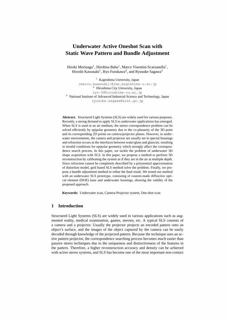
Fig. 1. (a) Epipolar geometry without water. (b) Epipolar geometry with water.
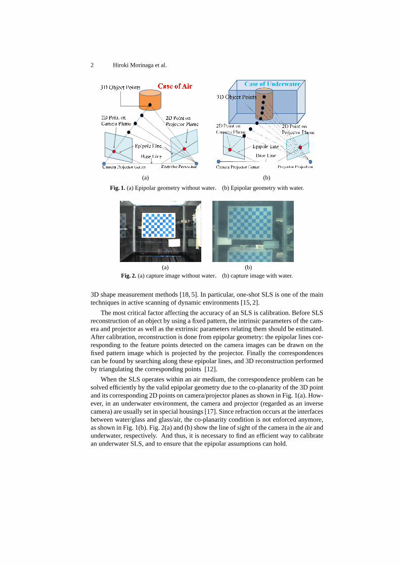
(a) (b)Fig. 2. (a) capture image without water. (b) capture image with water.
3D shape measurement methods [18, 5]. In particular, one-shot SLS is one of the maintechniques in active scanning of dynamic environments [15, 2].
The most critical factor affecting the accuracy of an SLS is calibration. Before SLSreconstruction of an object by using a fixed pattern, the intrinsic parameters of the cam-era and projector as well as the extrinsic parameters relating them should be estimated.After calibration, reconstruction is done from epipolar geometry: the epipolar lines cor-responding to the feature points detected on the camera images can be drawn on thefixed pattern image which is projected by the projector. Finally the correspondencescan be found by searching along these epipolar lines, and 3D reconstruction performedby triangulating the corresponding points [12].
When the SLS operates within an air medium, the correspondence problem can besolved efficiently by the valid epipolar geometry due to the co-planarity of the 3D pointand its corresponding 2D points on camera/projector planes as shown in Fig. 1(a). How-ever, in an underwater environment, the camera and projector (regarded as an inversecamera) are usually set in special housings [17]. Since refraction occurs at the interfacesbetween water/glass and glass/air, the co-planarity condition is not enforced anymore,as shown in Fig. 1(b). Fig. 2(a) and (b) show the line of sight of the camera in the air andunderwater, respectively. And thus, it is necessary to find an efficient way to calibratean underwater SLS, and to ensure that the epipolar assumptions can hold.
Underwater Active Oneshot Scan with Static Wave Pattern 3
This paper proposes three approaches to jointly tackle the aforementioned issues.First, we introduce a depth-dependent calibration method that uses a polynomial ap-proximation model for the SLS for underwater environment. Second, to solve the prob-lem that the epipolar geometry is only approximately valid underwater, we introducea grid-based active scanning method (specifically, a wave grid pattern) which allowsto find correspondences that stray away from the epipolar line while still maintaining agood matching performance. Since the results are based on approximate model, we alsointroduce a refinement algorithm based on bundle adjustment which uses the wave re-construction results as the initial parameters to achieve high accuracy. We demonstratethe effectiveness of the proposed approach with simulation as well as a real system witha special housing of camera and pattern projector placed underwater in a pool tank.
2 Related Work
Calibration models for underwater camera have been proposed extensively [14, 3, 13,1, 17, 10, 7, 6, 8]. However, none of them gives an entire calibration and reconstructionprocedure for an SLS. Because of the correspondence matching problem in SLS, someof the proposed models becomes invalid since the formulated models do not offer apractical strategy for matching and reconstruction. Besides, projector calibration un-derwater is also a slightly different issue than camera calibration due to the ”blindness”of the projector [4].
There are some early works for underwater 3D reconstruction based on approxima-tion model [14, 3, 13]. Queiroz-Netoet al.proposed an underwater model which simplyignores the effects of the refraction, but earns results with low accuracy due to the non-linear refraction effect [14]. Some approximate methods also have been proposed, suchas focal length adjustment [14], lens radial distortion approximation [3] and a combi-nation of the two [13]. Unfortunately, the accuracy of these approximation models arealso insufficient to an SLS system for correspondence search using epipolar geometry.
To improve the accuracy of underwater measurement, some physical models forcamera calibration and reconstruction have been proposed [1, 17, 10, 7, 6, 8]. Agrawalet al.gives a general calibration method for underwater cameras, based on a physical re-fractive model [1]. They consider that all refractive planes are parallel to each other, andthey derive front-projection and back-projection equations for their refractive model.However, it is necessary to solve 4th degree equations even for one refractive plane’scase, and 12th degree equations in the 2 plane case in a forward projection situation, andthus, it is difficult to use this method directly for SLS. Sedlazecket al. focus on the un-derwater light rays which are projected as a curved surface: after learning this surface,perspective projection can be done [17]. According to this method, it is also difficultto tackle the forward projection problem due to the complicated learning phase. Kanget al. and Sedlazeck also consider the underwater reconstruction with Structure fromMotion (SfM) [7, 6]. SfM is a passive way to recover 3D shape of objects, and it isdifficult to achieve a dense reconstruction result due to the difficulty of the correspon-dence searching. Kawahara et.al. proposed pixel-wise varifocal camera model, wherethe focal length of the projection varies pixel-by-pixel, for modeling non-central pro-jection of an underwater camera, and a calibration method for the cameras [8]. They
4 Hiroki Morinaga et al.
also proposed an active-stereo system composed of a projector and two cameras, whereprojection of the cameras and the projector is based on their model [9]. Since image-based correspondence search using epipolar lines are not valid for underwater cameras,they applied space carving method, where only photo-consistency is needed.
In terms of SLS for underwater, Camposet al.proposed an underwater active stereosystem that uses a DOE-based pattern projector [11]. They used a pattern of parallellines and each line is not coded into local features. Their decoding method (i.e., themethod for solving correspondences between the captured image and the projected pat-tern) relies on the order between the detected lines on the camera image, thus, ambiguitymay occur if only a small region of the pattern is detected.
3 Overview
3.1 System configuration
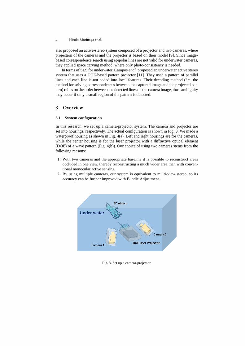
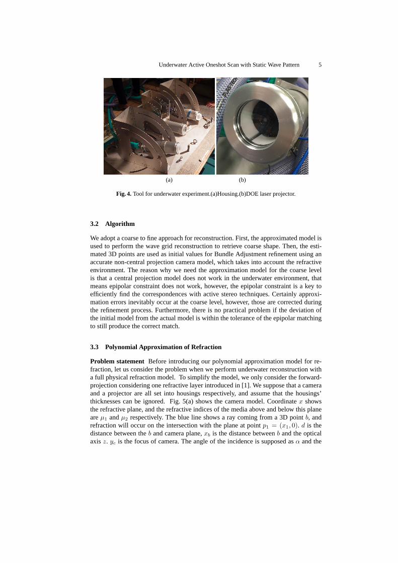
In this research, we set up a camera-projector system. The camera and projector areset into housings, respectively. The actual configuration is shown in Fig. 3. We made awaterproof housing as shown in Fig. 4(a). Left and right housings are for the cameras,while the center housing is for the laser projector with a diffractive optical element(DOE) of a wave pattern (Fig. 4(b)). Our choice of using two cameras stems from thefollowing reasons:
1. With two cameras and the appropriate baseline it is possible to reconstruct areasoccluded in one view, thereby reconstructing a much wider area than with conven-tional monocular active sensing.
2. By using multiple cameras, our system is equivalent to multi-view stereo, so itsaccuracy can be further improved with Bundle Adjustment.
Fig. 3.Set up a camera-projector.
Underwater Active Oneshot Scan with Static Wave Pattern 5
(a) (b)
Fig. 4.Tool for underwater experiment.(a)Housing.(b)DOE laser projector.
3.2 Algorithm
We adopt a coarse to fine approach for reconstruction. First, the approximated model isused to perform the wave grid reconstruction to retrieve coarse shape. Then, the esti-mated 3D points are used as initial values for Bundle Adjustment refinement using anaccurate non-central projection camera model, which takes into account the refractiveenvironment. The reason why we need the approximation model for the coarse levelis that a central projection model does not work in the underwater environment, thatmeans epipolar constraint does not work, however, the epipolar constraint is a key toefficiently find the correspondences with active stereo techniques. Certainly approxi-mation errors inevitably occur at the coarse level, however, those are corrected duringthe refinement process. Furthermore, there is no practical problem if the deviation ofthe initial model from the actual model is within the tolerance of the epipolar matchingto still produce the correct match.
3.3 Polynomial Approximation of Refraction
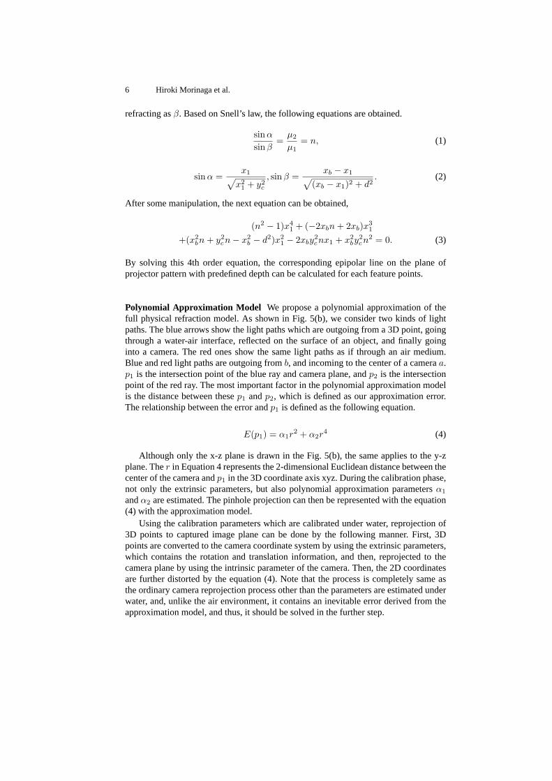
Problem statement Before introducing our polynomial approximation model for re-fraction, let us consider the problem when we perform underwater reconstruction witha full physical refraction model. To simplify the model, we only consider the forward-projection considering one refractive layer introduced in [1]. We suppose that a cameraand a projector are all set into housings respectively, and assume that the housings’thicknesses can be ignored. Fig. 5(a) shows the camera model. Coordinatex showsthe refractive plane, and the refractive indices of the media above and below this planeareµ1 andµ2 respectively. The blue line shows a ray coming from a 3D pointb, andrefraction will occur on the intersection with the plane at pointp1 = (x1, 0). d is thedistance between theb and camera plane,xb is the distance betweenb and the opticalaxisz. yc is the focus of camera. The angle of the incidence is supposed asα and the
6 Hiroki Morinaga et al.
refracting asβ. Based on Snell’s law, the following equations are obtained.
sinα
sinβ=
µ2
µ1= n, (1)
sinα =x1√
x21 + y2c
, sinβ =xb − x1√
(xb − x1)2 + d2. (2)
After some manipulation, the next equation can be obtained,
(n2 − 1)x41 + (−2xbn+ 2xb)x
31
+(x2bn+ y2cn− x2
b − d2)x21 − 2xby
2cnx1 + x2
by2cn
2 = 0. (3)
By solving this 4th order equation, the corresponding epipolar line on the plane ofprojector pattern with predefined depth can be calculated for each feature points.
Polynomial Approximation Model We propose a polynomial approximation of thefull physical refraction model. As shown in Fig. 5(b), we consider two kinds of lightpaths. The blue arrows show the light paths which are outgoing from a 3D point, goingthrough a water-air interface, reflected on the surface of an object, and finally goinginto a camera. The red ones show the same light paths as if through an air medium.Blue and red light paths are outgoing fromb, and incoming to the center of a cameraa.p1 is the intersection point of the blue ray and camera plane, andp2 is the intersectionpoint of the red ray. The most important factor in the polynomial approximation modelis the distance between thesep1 andp2, which is defined as our approximation error.The relationship between the error andp1 is defined as the following equation.
E(p1) = α1r2 + α2r
4 (4)
Although only the x-z plane is drawn in the Fig. 5(b), the same applies to the y-zplane. Ther in Equation 4 represents the 2-dimensional Euclidean distance between thecenter of the camera andp1 in the 3D coordinate axis xyz. During the calibration phase,not only the extrinsic parameters, but also polynomial approximation parametersα1
andα2 are estimated. The pinhole projection can then be represented with the equation(4) with the approximation model.
Using the calibration parameters which are calibrated under water, reprojection of3D points to captured image plane can be done by the following manner. First, 3Dpoints are converted to the camera coordinate system by using the extrinsic parameters,which contains the rotation and translation information, and then, reprojected to thecamera plane by using the intrinsic parameter of the camera. Then, the 2D coordinatesare further distorted by the equation (4). Note that the process is completely same asthe ordinary camera reprojection process other than the parameters are estimated underwater, and, unlike the air environment, it contains an inevitable error derived from theapproximation model, and thus, it should be solved in the further step.
Underwater Active Oneshot Scan with Static Wave Pattern 7
c(0, yc)
b(xb, -d)
p1(x1, 0)
z
x
d
1µ
2µ
α
β
c(0, yc)
b(xb, -d)
p2(x2, 0)
p1(x1, 0)
z
x
d
1µ
2µ
α
β
(a) (b)
Fig. 5. (a) physical camera refraction model. (b) polynomial approximation camera refractionmodel.
4 Depth dependent calibration
4.1 Overview of the calibration process
First, the camera and projector are put into their respective housings, and placed into apool filled with water. After that, the intrinsic parameters of the camera are estimatedwith a checkerboard [19]. Then, the intrinsic parameters of the projector and the extrin-sic parameters between them are estimated by a second calibration using a sphere ofknown size, described in the next section.
Since the effect of refraction is depth dependent, we conduct the calibration at themultiple depth in the paper. From the multiple calibration results, it is possible to rep-resent the refraction effect with several hyper parameters. However, we take anothersolution to cope with a depth dependent effect in the paper for simplicity and leavethe hyper parameter estimation approach for our future task. In order to retrieve a dis-crete set of depth-dependent calibration parameters, we put the calibration objects,i.e.,checker board planes and sphere, at multiple depth and conduct calibrations indepen-dently.
For the selection of the best parameters, the residual errors of epipolar constraintsare used. To achieve this, the 3D reconstruction process is conducted for all the param-eter sets independently. The sum of residual errors of the correspondences, which arenormally errors of epipolar constraints, is calculated and used for the selection of thebest result.
4.2 Sphere based projector calibration
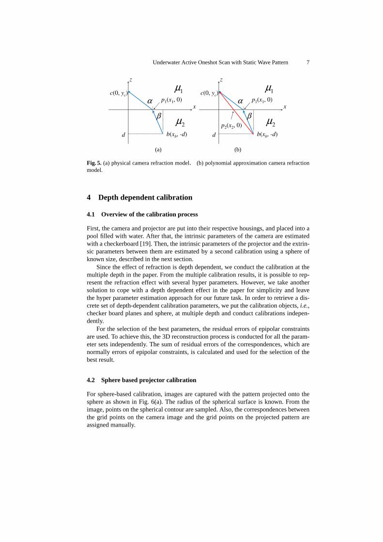
For sphere-based calibration, images are captured with the pattern projected onto thesphere as shown in Fig. 6(a). The radius of the spherical surface is known. From theimage, points on the spherical contour are sampled. Also, the correspondences betweenthe grid points on the camera image and the grid points on the projected pattern areassigned manually.
8 Hiroki Morinaga et al.
Projector
Simulated
image
Camera
Sphere
Auxiliary plane
c
gc2
gc1gi1
gi2
gp1
gp2 Rx+t
s~
22)~( csc −
r
(a) (b)
Fig. 6. Calibration of intrinsic/extrinsic parameters of the pattern projector by sphere object: (a)pattern projection on a sphere, (b) calibration errors.
For the calibration process, we minimize reprojection errors between the imagedgrid points on the sphere and the simulated grid positions, with respect to the extrinsicparameters, the intrinsic parameters of the projector, and the position of the calibrationsphere. Fig. 6(b) shows how the simulated grid positions are calculated. From a gridpoint (for example,gp1 in Fig. 6(b)) of the projector, the gird projection on the sphere(gc1) is calculated by ray-tracing, and is projected to the camera (gi1). If the ray of thegrid point does not intersect with the sphere (for example,gp2), we use intersectionof the ray with an auxiliary plane (gc2) that is fronto-parallel and includes the spherecenter.
Other than the reprojection errors, points on the spherical contour are also used forthe optimization. The line of sight of a contour point (s in Fig. 6(b)) should be tangentto the sphere in the 3D space; thus, the distance between the spherical center (c) andthe line should equal to the sphere radius (r). Thus, the difference between the distancefrom the spherical object and the radius (
√∥c∥2 − (s · c)− r) is also considered to be
an error. Thus, the sum of squares of these errors is minimized by using Levenberg-Marquardt method.
5 3D Reconstruction
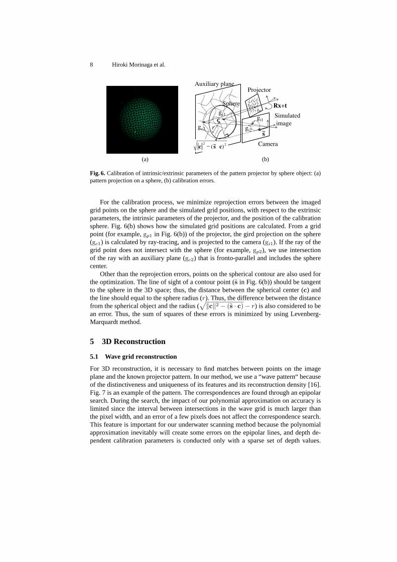
5.1 Wave grid reconstruction
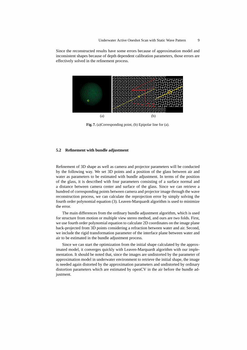
For 3D reconstruction, it is necessary to find matches between points on the imageplane and the known projector pattern. In our method, we use a “wave pattern“ becauseof the distinctiveness and uniqueness of its features and its reconstruction density [16].Fig. 7 is an example of the pattern. The correspondences are found through an epipolarsearch. During the search, the impact of our polynomial approximation on accuracy islimited since the interval between intersections in the wave grid is much larger thanthe pixel width, and an error of a few pixels does not affect the correspondence search.This feature is important for our underwater scanning method because the polynomialapproximation inevitably will create some errors on the epipolar lines, and depth de-pendent calibration parameters is conducted only with a sparse set of depth values.
Underwater Active Oneshot Scan with Static Wave Pattern 9
Since the reconstructed results have some errors because of approximation model andinconsistent shapes because of depth dependent calibration parameters, those errors areeffectively solved in the refinement process.
(a) (b)
Fig. 7. (a)Corresponding point, (b) Epipolar line for (a).
5.2 Refinement with bundle adjustment
Refinement of 3D shape as well as camera and projector parameters will be conductedby the following way. We set 3D points and a position of the glass between air andwater as parameters to be estimated with bundle adjustment. In terms of the positionof the glass, it is described with four parameters consisting of a surface normal anda distance between camera center and surface of the glass. Since we can retrieve ahundred of corresponding points between camera and projector image through the wavereconstruction process, we can calculate the reprojection error by simply solving thefourth order polynomial equation (3). Leaven-Marquardt algorithm is used to minimizethe error.
The main differences from the ordinary bundle adjustment algorithm, which is usedfor structure from motion or multiple view stereo method, and ours are two folds. First,we use fourth order polynomial equation to calculate 2D coordinates on the image planeback-projected from 3D points considering a refraction between water and air. Second,we include the rigid transformation parameter of the interface plane between water andair to be estimated in the bundle adjustment process.
Since we can start the optimization from the initial shape calculated by the approx-imated model, it converges quickly with Leaven-Marquardt algorithm with our imple-mentation. It should be noted that, since the images are undistorted by the parameter ofapproximation model in underwater environment to retrieve the initial shape, the imageis needed again distorted by the approximation parameters and undistorted by ordinarydistortion parameters which are estimated by openCV in the air before the bundle ad-justment.
10 Hiroki Morinaga et al.
6 Experiments
6.1 Depth dependent calibration
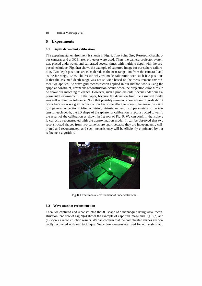
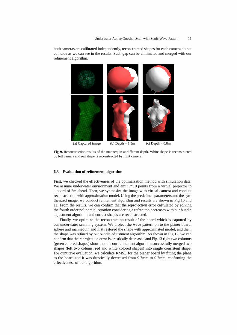
The experimental environment is shown in Fig. 8. Two Point Grey Research Grasshop-per cameras and a DOE laser projector were used. Then, the camera-projector systemwas placed underwater, and calibrated several times with multiple depth with the pro-posed technique. Fig. 9(a) shows the example of captured image for our sphere calibra-tion. Two depth positions are considered, as the near range, 1m from the camera 0 andas the far range, 1.5m. The reason why we made calibration with such few positionsis that the assumed depth range was not so wide based on the measurement environ-ment we applied. As wave grid reconstruction applied in our method works using theepipolar constraint, erroneous reconstruction occurs when the projection error turns tobe above our matching tolerance. However, such a problem didn’t occur under our ex-perimental environment in the paper, because the deviation from the assumed modelwas still within our tolerance. Note that possibly erroneous connection of grids didn’toccur because wave grid reconstruction has some effect to correct the errors by usinggrid pattern connections. After acquiring intrinsic and extrinsic parameters of the sys-tem for each depth, the 3D shape of the sphere for calibration is reconstructed to verifythe result of the calibration as shown in 1st row of Fig. 9. We can confirm that sphereis correctly reconstructed with the approximation model. It can be observed that tworeconstructed shapes from two cameras are apart because they are independently cali-brated and reconstructed, and such inconsistency will be efficiently eliminated by ourrefinement algorithm.
Fig. 8.Experimental environment of underwater scan.
6.2 Wave oneshot reconstruction
Then, we captured and reconstructed the 3D shape of a mannequin using wave recon-struction. 2nd row of Fig. 9(a) shows the example of captured image and Fig. 9(b) and(c) shows a reconstruction results. We can confirm that the complicated shapes are cor-rectly recovered with our technique. Since two cameras are used for our system and
Underwater Active Oneshot Scan with Static Wave Pattern 11
both cameras are calibrated independently, reconstructed shapes for each camera do notcoincide as we can see in the results. Such gap can be eliminated and merged with ourrefinement algorithm.
(a) Captured image (b) Depth = 1.5m (c) Depth = 0.8m
Fig. 9. Reconstruction results of the mannequin at different depth. White shape is reconstructedby left camera and red shape is reconstructed by right camera.
6.3 Evaluation of refinement algorithm
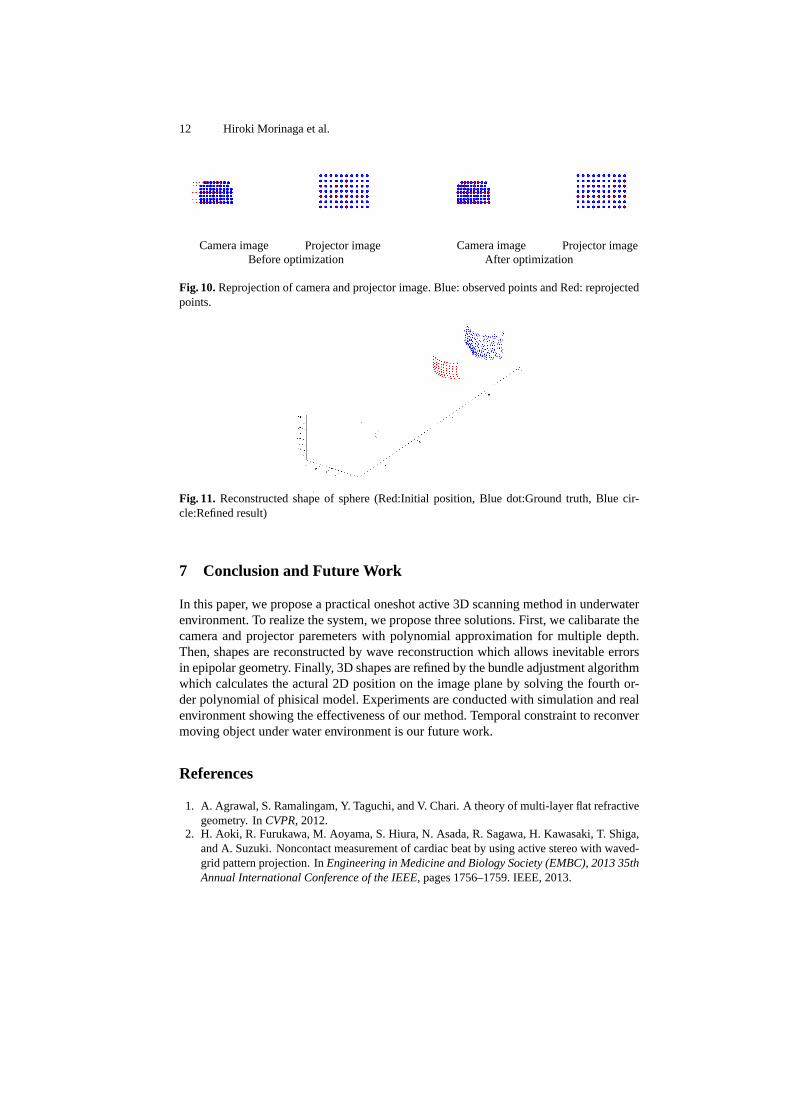
First, we checked the effectiveness of the optimaization method with simulation data.We assume underwater environment and emit 7*10 points from a virtual projector toa board of 2m ahead. Then, we synthesize the image with virtual camera and conductreconstruction with approximation model. Using the predefined parameters and the syn-thesized image, we conduct refinement algorithm and results are shown in Fig.10 and11. From the results, we can confirm that the reprojection error calculated by solvingthe fourth order polinomial equation considering a refraciton decreases with our bundleadjustment algorithm and correct shapes are reconstructed.
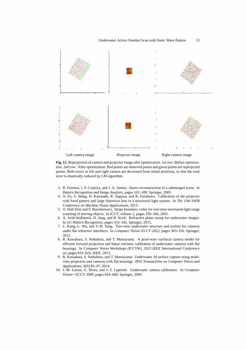
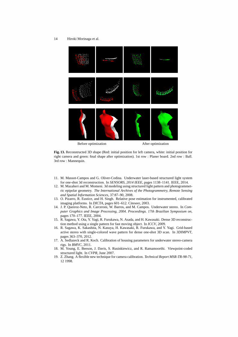
Finally, we optimize the reconstruction result of the board which is captured byour underwater scanning system. We project the wave pattern on to the planer board,sphere and mannequin and first restored the shape with approximated model, and then,the shape was refined by out bundle adjustment algorithm. As shown in Fig.12, we canconfirm that the reprojection error is drastically decreased and Fig.13 right two columns(green colored shapes) show that the our refinement algorithm successfully merged twoshapes (left two colums, red and white colored shapes) into single consistent shape.For quntitave evaluation, we calculate RMSE for the planer board by fitting the planeto the board and it was drestically decreased from 9.7mm to 0.7mm, confirming theeffectiveness of our algorithm.
12 Hiroki Morinaga et al.
Camera image Projector image Camera image Projector imageBefore optimization After optimization
Fig. 10.Reprojection of camera and projector image. Blue: observed points and Red: reprojectedpoints.
Fig. 11. Reconstructed shape of sphere (Red:Initial position, Blue dot:Ground truth, Blue cir-cle:Refined result)
7 Conclusion and Future Work
In this paper, we propose a practical oneshot active 3D scanning method in underwaterenvironment. To realize the system, we propose three solutions. First, we calibarate thecamera and projector paremeters with polynomial approximation for multiple depth.Then, shapes are reconstructed by wave reconstruction which allows inevitable errorsin epipolar geometry. Finally, 3D shapes are refined by the bundle adjustment algorithmwhich calculates the actural 2D position on the image plane by solving the fourth or-der polynomial of phisical model. Experiments are conducted with simulation and realenvironment showing the effectiveness of our method. Temporal constraint to reconvermoving object under water environment is our future work.
References
1. A. Agrawal, S. Ramalingam, Y. Taguchi, and V. Chari. A theory of multi-layer flat refractivegeometry. InCVPR, 2012.
2. H. Aoki, R. Furukawa, M. Aoyama, S. Hiura, N. Asada, R. Sagawa, H. Kawasaki, T. Shiga,and A. Suzuki. Noncontact measurement of cardiac beat by using active stereo with waved-grid pattern projection. InEngineering in Medicine and Biology Society (EMBC), 2013 35thAnnual International Conference of the IEEE, pages 1756–1759. IEEE, 2013.
Underwater Active Oneshot Scan with Static Wave Pattern 13
Left camera image Projector image Right camera image
Fig. 12.Reprojection of camera and projector image after optimization. 1st row: Before optimiza-tion. 2nd row : After optimization. Red points are observed points and green points are reprojectedpoints. Both errors in left and right camera are decreased from initial positions, so that the totalerror is drastically reduced by LM algorithm.
3. R. Ferreira, J. P. Costeira, and J. A. Santos. Stereo reconstruction of a submerged scene. InPattern Recognition and Image Analysis, pages 102–109. Springer, 2005.
4. X. Fu, Z. Wang, H. Kawasaki, R. Sagawa, and R. Furukawa. Calibration of the projectorwith fixed pattern and large distortion lens in a structured light system. InThe 13th IAPRConference on Machine Vision Applications, 2013.
5. O. Hall-Holt and S. Rusinkiewicz. Stripe boundary codes for real-time structured-light rangescanning of moving objects. InICCV, volume 2, pages 359–366, 2001.
6. A. Jordt-Sedlazeck, D. Jung, and R. Koch. Refractive plane sweep for underwater images.In GC Pattern Recognition, pages 333–342. Springer, 2013.
7. L. Kang, L. Wu, and Y.-H. Yang. Two-view underwater structure and motion for camerasunder flat refractive interfaces. InComputer Vision–ECCV 2012, pages 303–316. Springer,2012.
8. R. Kawahara, S. Nobuhara, and T. Matsuyama. A pixel-wise varifocal camera model forefficient forward projection and linear extrinsic calibration of underwater cameras with flathousings. InComputer Vision Workshops (ICCVW), 2013 IEEE International Conferenceon, pages 819–824. IEEE, 2013.
9. R. Kawahara, S. Nobuhara, and T. Matsuyama. Underwater 3d surface capture using multi-view projectors and cameras with flat housings.IPSJ Transactions on Computer Vision andApplications, 6(0):43–47, 2014.
10. J.-M. Lavest, G. Rives, and J.-T. Lapreste. Underwater camera calibration. InComputerVision―ECCV 2000, pages 654–668. Springer, 2000.
14 Hiroki Morinaga et al.
Before optimization After optimization
Fig. 13.Reconstructed 3D shape (Red: initial position for left camera, white: initial position forright camera and green: final shape after optimization). 1st row : Planer board. 2nd row : Ball.3rd row : Mannequin.
11. M. Massot-Campos and G. Oliver-Codina. Underwater laser-based structured light systemfor one-shot 3d reconstruction. InSENSORS, 2014 IEEE, pages 1138–1141. IEEE, 2014.
12. M. Mazaheri and M. Momeni. 3d modeling using structured light pattern and photogrammet-ric epipolar geometry.The International Archives of the Photogrammetry, Remote Sensingand Spatial Information Sciences, 37:87–90, 2008.
13. O. Pizarro, R. Eustice, and H. Singh. Relative pose estimation for instrumented, calibratedimaging platforms. InDICTA, pages 601–612. Citeseer, 2003.
14. J. P. Queiroz-Neto, R. Carceroni, W. Barros, and M. Campos. Underwater stereo. InCom-puter Graphics and Image Processing, 2004. Proceedings. 17th Brazilian Symposium on,pages 170–177. IEEE, 2004.
15. R. Sagawa, Y. Ota, Y. Yagi, R. Furukawa, N. Asada, and H. Kawasaki. Dense 3D reconstruc-tion method using a single pattern for fast moving object. InICCV, 2009.
16. R. Sagawa, K. Sakashita, N. Kasuya, H. Kawasaki, R. Furukawa, and Y. Yagi. Grid-basedactive stereo with single-colored wave pattern for dense one-shot 3D scan. In3DIMPVT,pages 363–370, 2012.
17. A. Sedlazeck and R. Koch. Calibration of housing parameters for underwater stereo-camerarigs. InBMVC, 2011.
18. M. Young, E. Beeson, J. Davis, S. Rusinkiewicz, and R. Ramamoorthi. Viewpoint-codedstructured light. InCVPR, June 2007.
19. Z. Zhang. A flexible new technique for camera calibration.Technical Report MSR-TR-98-71,12 1998.