Embed Size (px)
Citation preview

United States Patent (19) Endou et al.
WATER QUALITY CONTROL METHOD, AND METHOD AND APPARATUS FOR MEASURING ELECTRICAL CONDUCTIVITY USED IN THE WATER QUALITY CONTROL
54
Inventors: Masao Endou, Hitachi; Yamato Asakura, Katsuta; Atsushi Watanabe, Hitachi; Masaharu Sakagami, Katsuta; Shunsuke Uchida; Makoto Nagase, both of Hitachi; Tsutomu Baba, Katsuta; Katsumi Ohsumi, Hitachi, all of Japan
75
73) Assignee: Hitachi, Ltd., Tokyo, Japan
21) Appl. No.: 141,424
22 Filed: Jan. 7, 1988
Foreign Application Priority Data Japan .................................... 62-1651 Japan .. ... 62-114660 Japan ................................ 62-221916
30 Jan. 9, 1987 (JP)
May 13, 1987 JP Sep. 7, 1987 (JP)
51 Int. Cl." ...................... G01N 27/06; G01N 27/02 52 U.S. C. .................................... 324/441; 324/444;
324/439; 324/57 R; 204/408 58) Field of Search ..................... 324/57 R, 439, 441,
324/442, 444, 446, 450, 71.2, 65 CR; 204/1 T, 404, 406, 408; 364/497
Il MEASURING AND CONTROL UNIT
MEASURED CURRENT
2
CACULATION DEVICE
APP FR EEN CY
CURRENT/VOLTAGE
AC FREQ. SWEEP SIGNAL
CONTROL UNIT
11 Patent Number: 4,853,638 (45) Date of Patent: Aug. 1, 1989
56) References Cited U.S. PATENT DOCUMENTS
4,176,031 1 1/1979 Rosenblum ......................... 2O4/408 4,204,259 5/1980 Yabe .................................... 364/497 4,238,298 12/1980 Tsuru et al. ........... ... 324/57 RX 4,445,091 4/1984 Kisebauch et al. ............ 324/439 X 4,626,338 12/1986 Kondo et al. ...... ... 204/408 X 4,682,113 7/1987 Barben, II ........................... 324/.441
FOREIGN PATENT DOCUMENTS
59-60293 6/1984 Japan. Primary Examiner-Reinhrd J. Eisenzopf Assistant Examiner-Jack B. Harvey Attorney, Agent, or Firm-Antonelli, Terry & Wands 57 ABSTRACT Electric conductivities of an aqueous solution under measurement are measured at two or more different temperatures in a range To to Tn, and a relationship between the electrical conductivity and the tempera tures is obtained. A solute substance in the aqueous solution is determined by applying this relationship against a known temperature and electrical conductiv ity relationship of an individual substance. A concentra tion of the determined substance is estimated by apply ing the electrical conductivity at the lowest tempera ture To to a known relationship between an electrical conductivity and a concentration at the same tempera ture To with respect to an individual substance.
15 Claims, 19 Drawing Sheets
APPLIED
VOLTAGE
U.S. Patent Aug. 1, 19 Sheet 1 of 19 4,853,638
F G.
(MEASURED WALUES) ROOMTEMPERATUREELECTRICAL CONDUCTIVITY puS/cm
a SQEMERAUREELECTRICAL ^ CONDUCTIVITY 5us/cm / ROOMTEMPERATUREELECTRICAL
3O M CONDUCTIVITY OuS/cm
25 / (CALCULATED VALUE) , --- COMPLETE DISSOCATION (ASSUMED)
IOO 20O 3OO TEMPERATURE (C)


U.S. Patent Aug. 1, 1989 Sheet 3 of 19 4,853,638
F G. 4
CURRENT/ VOLTAGE a- 1 -
MEASURING AND CONTROL
MEASURED MEASURED APPLIED CURRENT VOLTAGE AC VOLAGE
2 AC MPEDANCE ANALYZER
AC MPEDANCE
AC FREQUENCY SWEEP SIGNAL
3 APPLIED FREQUENCY CONTROL UNIT

U.S. Patent Aug. 1, 1989 Sheet 4 of 19 4,853,638
F. G. 5 C.
5OK WATER TEMPERATURE: 5C
G S. E
O 5OK OOK Re CZ) (S))
F. G. 5b
3K 6 WATER TEMPERATURE:3OOC
S. E
O 3K 6K Re (Z) (S2)

U.S. Patent Aug. 1, 1989 Sheet 5 of 19 4,853,638
F. G. 6
8
7 |7 6
--&-- Rf Rf
U.S. Patent Aug. 1, 1989 Sheet 6 of 19 4,853,638 F G. 7
up : FREQUENCY
() nox = 1 / ( C Rf) : Re (Z) ( S) )
F G. 8
O OO 2OO 3OO WATER TEMPERATURE (C)

U.S. Patent Aug. 1, 1989 Sheet 8 of 19 4,853,638
E S 4. O /k, (2 3.6 o W S. f \
3.2 f W
R I A. S 2.4 I
2 2.O g 8 f o ELECTRODE INTERVAL 2mm
.. 6 / A ELECTRODE INTERVAL 5mm 3 1.2 ? OELECTRODE INTERVAL 2nn i O. 8 9' - - - CALCULATED VALUE i -
O OO 2OO 3OO
WATER TEMPERATURE (C)

U.S. Patent Aug. 1, 1989 Sheet 9 of 19 4,853,638 F G.
Il CURRENT/VOLTAGE MEASURING AND CONTROL UNIT
CAL CULATION DEVICE
APPLIED AEEE2.Ncy CONTROL UNIT

U.S. Patent Aug. 1, 1989 Sheet 10 of 19 4,853,638
F. G. 3
2K O MEASURED WALUE (5mm NTERVAL) A MEASURED WALUE (3mm NTERVAL)
ELECTRICAL CONDUCTIVITY 2OuS/cm C
N IK E

U.S. Patent Aug. 1, 1989 Sheet 11 of 19 4,853,638 F G. 4
x O3
O 2 4. 6 8 ROOM TEMPERATURE ELECTRICAL CONDUCTIVITY(us/cm)
F. G. 5
5
O OO 2 OO 3OO 4OO
TEMPERATURE (C)

U.S. Patent Aug. 1, 1989 Sheet 12 of 19
/
7O o Ao MEASURED VALUE / a --- CALUATEDVALUE/ 5 Sion, ?o-o f M
6o ASSUMED ) // S. NPURITY W / \
/ 5O N O2 So4 //O s > ROOM TEMPERATURE 4/ / H ELECTRICAL t / 9 4OHCONDUCTIVITY / C) 9.5uS/cm M 2 N- M O / O 3O A A s A^TA-aa C / A1 47ts/cm 2O /
/ A l.OALS/Cm i O---- - C N O / u N
/ O O
3OO 2OO
TEMPERATURE (C)
O OO
4.853,638

U.S. Patent Aug. 1, 1989 Sheet 13 of 19 4,853,638
F. G. 7
E O 6
O. O OO
HIGH TEMPERATURE ELECTRICAL CONDUCTIVITY AT 288°C (LLS/cm )
U.S. Patent Aug. 1, 1989 Sheet 14 of 19 4.853,638
F. G. 8
OF MATERIAL SUS 3O4 TEMP. 288°C Do I2OOppb EAN33xots - Na2SO4
- c U
E
O. O OO
ROOM TEMPERATURE ELECTRICAL CONDUCTIVITY (us/cm)
U.S. Patent Aug. 1, 1989 Sheet 15 of 19 4,853,638
4 1. ROOM TEMP.
M ELECTRICAL CONDUCTIVITY
2 1 plS/cm MPURITY
O OH2SO4. ANCOH ONd2SO4
--- CALCULATED VALUE UNDER THE ASSUMPTION OF COMPLETE DISSOCATION
8
O OO 2OO 3OO
WATER TEMPERATURE (C)

U.S. Patent Aug. 1, 1989 Sheet 16 of 19 4.853,638
E2, EXE 7 O / CONDUCTIVITY LS/cm
/ O IMPURITY Un O H2SO4
6O // A NaOH // 1 Na2SO4
1. 1AA-R --- CALCULATED 5 O /, P(a R VALUE UNDER
A/22 THE ASSUMPTION 14 OF COMPLETE
M DISSOCATION 4O 7
1. 1 1. 1. e
3O ? 1
O MEASURED VALUE OF PURE WATER
- a- - - - ar
- - - -
O OO 2OO 3OO WATER TEMPERATURE (C)

U.S. Patent Aug. 1, 1989 Sheet 17 of 19 4,853,638
6O
S No C2 n CO
S
is 4O s d
? 2 O C
- C. H2SO4. O 2O
s -
O OO 2OO 3OO
TEMPERATURE (C)

U.S. Patent Aug. 1, 1989 She 18 of 19 4.853,638
O 6 O
35 SS g 9N
t
O 4O CN
g O
X
S2 L
S 2O G ROOM TEMPERATURE 55 ELECTRICAL CONDUCTIVITY Ou.S/cm E3
O
O 5O OO
CONTRIBUTION RATE OF NOC0 TO ROOM TEMP, ELECTRICAL CONDUCTIVITY OF AGUEOUS H2SO4 SOLUTION (%)

U.S. Patent Aug. 1, 1989 Sheet 19 of 19
F. G. 23
4.853,638
HIGH TEMP. ELECTRICAL 2 4 CONDUCTWiTYNEER
CATION 22EXCHAGE
BODY
DEVICE
LiOH 28 CONCENTRATION
REGULATING
DISSOCATION EVALUATION
St. TEMP EVALUAT DEV ON

4,853,638 1.
WATER QUALITY CONTROL METHOD, AND METHOD AND APPARATUS FOR MEASURING ELECTRICAL CONDUCTIVITY USED IN THE
WATER QUALITY CONTROL
BACKGROUND OF THE INVENTION
The present invention relates to a water quality con trol method, and a method and apparatus for measuring an electrical conductivity used in the water quality control. In particular, the present invention relates to water quality control of high temperature water in atomic and thermal power plants, detection of the cor rosion rate of a metallic structural member disposed in the aqueous solution in the plants, and to a method and apparatus for measuring electrical conductivity used in the detection of the corrosion rate. Minute amount of impurities contained in high tem
perature water affect the corrosion of an analytical metallic material. Accordingly in atomic and thermal power plants, the high temperature water is sampled, and after cooling down and reducing the pressure, elec trical conductivity is continuously monitored at room temperature to achieve the water quality control so that the measured value of the room temperature electrical conductivity does not exceed a tolerance value. Specifi cally, in the prior art, a room temperature electrical conductivity measuring method has been applied for the purpose of continuous monitoring of a corrosive
O
15
20
25
environment and continuous monitoring of inclusion of 30 impurities. Such a water quality control method using the room temperature electrical conductivity measuring apparatus is proposed in Japanese Patent Laid-Open Publication No. 59-60293 (1984). However, in the method mentioned above, it is diffi
cult to accurately evaluate the high temperature electri cal conductivity at corrosive environment temperatures based on the measured values at room temperature because the dissociation of the water perse or the disso ciation of the impurities, and the mobility of ions have respectively different temperature dependencies. As a result, in the prior art high temperature water quality control method using the room temperature electrical conductivity, the setting of a standard value for the water quality control is empirical, and the setting of a generally applicable and rational standard value is diffi cult. Furthermore, even when the room temperature electrical conductivity is the same, since the effect on the corrosion rate in high temperature water differs significantly depending on the chemical form of con tained impurities, a problem is involved in that the set ting of the standard value for the control of the room temperature electrical conductivity becomes more se were than needed.
Additionally, in the prior art method, the analyzing operation in the analysis of a chemical form of impuri ties is conducted on the off-line basis, and thus, the analyzing time becomes long. Consequently, it is diffi cult to detect rapidly formed impurity substances when the water quality is changed abruptly. In particular, it is difficult to detect Cl ion which accelerates the corro sion in high temperature water peculiarly, and to diag nose the cause of the abnormalities.
SUMMARY OF THE INVENTION
An object of the present invention is to realize the rational water quality control in place of the prior art water quality control which uses the room temperature
35
45
50
55
65
2 electrical conductivity as an indicator, wherein the high temperature electrical conductivity at a corrosive envi ronment temperature and the temperature dependency of the electrical conductivity in a temperature range from the corrosive environment temperature to the room temperature are used as indicators, and the influ ence of the chemical form of impurities on the corrosion in relatively high temperature water is taken into con sideration.
In one aspect of a method of water quality control in accordance with the present invention, the method comprises the steps of:
(a) measuring electrical conductivities of an aqueous solution under measurement at two or more different temperatures in a range of To to Tn, and obtaining a relationship between the electrical conductivity and the temperature;
(b) determining a solute substance in the aqueous solution under measurement by applying the relation ship obtained in the step (a) to a relationship between a temperature and an electrical conductivity of an indi vidual substance obtained beforehand, and
(c) estimating a concentration of the determined sub stance by applying the electrical conductivity at a low est temperature To among the measurement tempera tures in the step (a) to a relationship between an electri cal conductivity and a concentration at the same tem perature To in an individual substance obtained before hand.
In another aspect of a method of water quality con trol in accordance with the present invention, the method comprises the steps of: (A) immersing at least a pair of electrodes in an aque
ous solution under measurement in order to obtain a relationship between an electrical conductivity and a temperature by measuring electrical conductivities at least at two different temperatures in a range of To to Tn with respect to the aqueous solution under measure ment, and measuring complex AC impedances of the aqueous solution between the pair of electrodes at each of the temperatures by applying an AC voltage between the pair of electrodes while varying a frequency of the AC voltage;
(B) obtaining a liquid resistance of the aqueous solu tion under measurement at each of the measurement temperatures from a frequency response of each of the complex AC impedances;
(C) obtaining an electrical conductivity at each of the measurement temperatures in the range of To to Tn from the liquid resistance; (D) deciding a corrosion rate of a metallic structural
member in contact with the aqueous solution by apply ing a relationship between a highest temperature in the measurement temperatures in the range of To to Tn and the electrical conductivity to a relationship between an electrical conductivity and a corrosion rate of an indi vidual substance obtained beforehand;
(E) determining a solute substance in the aqueous solution under measurement by applying the relation ship between the measurement temperature in the tem perature range of To to Tn and the electrical conductiv ity to a relationship between a temperature and an elec trical conductivity of an individual substance obtained beforehand; and
(F) with respect to the determined substance, estimat ing a concentration of the substance by applying a part of the relationship obtained in the step (C), that is, the

4,853,638 3
relationship between the temperature and the electrical conductivity at a lowest temperature To, to a relation ship between an electrical conductivity and a concen tration at the same temperature To with respect to an individual substance obtained beforehand. The invention was made based on the following new
findings by the inventors of the present application. (1) Even when a solute substance is a strong electro
lyte, it becomes substantially difficult to dissociate com pletely in water at a relatively higher temperature than a room temperature. In other words, in the high temper ature water, the concentration of a molecular solute substance which does not dissociate to ions can not be neglected with respect to a concentration of an ionized solute substance. --
(2) There is a significant correlation between a high temperature electrical conductivity in an incomplete dissociating condition and a corrosion rate in high tem perature water, and the corrosion rate increases in pro portion to power of the high temperature electrical conductivity.
(3) The extent of incomplete dissociation changes depending upon the kind of the solute substance, and in particular, a difference between the electric conductivi ties of different solute substances becomes significant in a high temperature region at 150 C. or higher.
(4) Since the corrosion rate in high temperature water increases not depending upon the chemical form of the impurity but in proportion to power of the high tem perature electrical conductivity, it is possible to accu rately control the corrosive environment, by using the high temperature electrical conductivity at a corrosive environment temperature as an indicator, based on a common standard value which is not dependent upon the chemical form of the included impurity.
(5) A pattern of electrical conductivity change with temperature exhibits a unique pattern depending upon the kind of solute impurity substances. Thus, the kind of solute impurity substance can be determined by com paring the patterns obtained by measuring the high temperature electrical conductivity at one or a plurality of temperatures in a temperature region higher than the room temperature in which region the solute substance does not dissociate completely. For example, it is possi ble to decide the presence or absence of Clion which is known to have a unique accelerating effect on the cor rosion of stainless steel in high temperature water. When the presence of the Cl ion is determined, the concentration of the Clion caribe determined quantita tively by using an actually measured value of the elec trical conductivity in a temperature region, for example, at a room temperature, in which the solute substance is substantially perfectly dissociated. Thus, it is possible to perform the on-line analysis/control of the Clion con centration.
BRIEF DESCRIPTION OF THE DRAWINGS
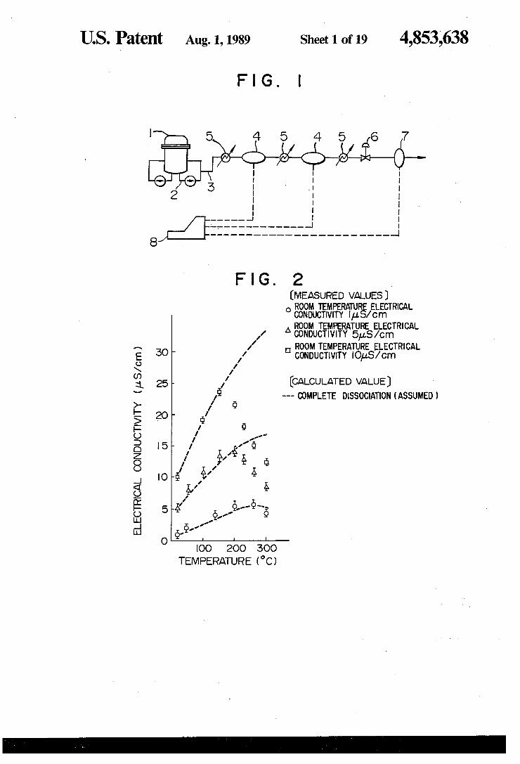
FIG. 1 is a schematic diagram showing a basic ar rangement of a BWR type nuclear reactor primary cooling system to which the present invention is ap plied;
FIG. 2 is a graph showing a comparison between measured values and calculated values of temperature dependency of the electrical conductivity in an aqueous H2SO4 solution; FIG. 3 is a flowchart showing an example of a high
temperature water quality control system to which the present invention is applied;
5
10
15
20
25
30
35
40
45
50
55
65
4. FIG. 4 is a schematic diagram showing a basic ar
rangement of a measuring apparatus used to measure a high temperature electrical conductivity; FIGS. 5A and 5B are graphs showing a frequency
response of the electrode impedance of platinum elec trodes dipped in pure water, plotted on the complex plane in a frequency range from 1 Hz to 100 kHz;
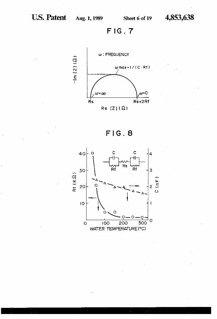
FIG. 6 is a diagram showing an electrical equivalent circuit of the measuring electrode set estimated from the result of analysis of the frequency response of the electrode impedance; FIG. 7 is a graph showing a locus of the frequency
response of a theoretical AC impedance represented by the electrical equivalent circuit of the measuring elec trode set;
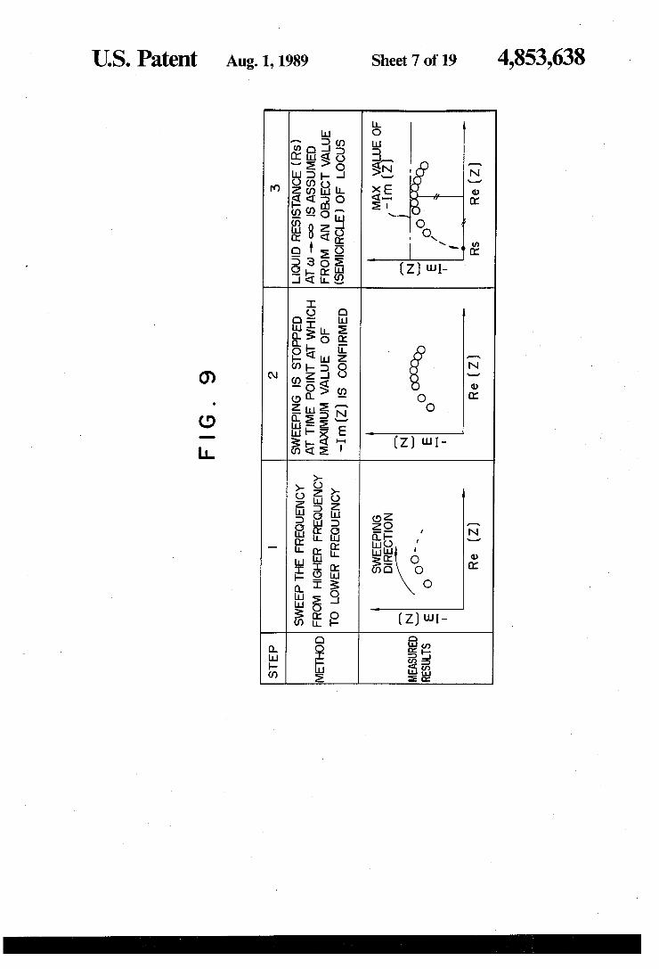
FIG. 8 is a graph showing temperature dependencies of a measuring electrode surface reaction resistance and an electrode capacitance; FIG. 9 is a diagram illustrating the control performed
by the applied frequency control device in FIG. 1 which is unique in the present invention;
FIG. 10 is a graph showing a comparison between measured results and theoretical calculation results when the present invention is applied to the measure ment of electrical conductivity of pure water; FIG. 11 is a schematic diagram showing an arrange
ment of another measuring apparatus used in the mea surement of the high temperature electrical conductiv ity;
FIG. 12 is a diagram showing a structure of the elec trode set; FIG. 13 is a graph showing the results of analysis of
a frequency response of the electrode impedance when the electrode set is dipped in a high electrical conduc tivity liquid; FIG. 14 is a graph showing a correlation between the
results of measurement of a liquid resistance at room temperature by a measuring apparatus of the present invention and the results, of measurement by an electri cal conductivity measuring apparatus available in the market;
FIG. 15 is a graph showing changes in equivalention electrical conductivity with temperature which is used in calculating the high temperature electrical conduc tivity; FIG. 16 is a graph showing a comparison between
changes in measured value and theoretical calculation value of the electrical conductivity with temperature when Na2SO4 is dissolved as an impurity; FIG. 17 is a graph showing a correlation between the
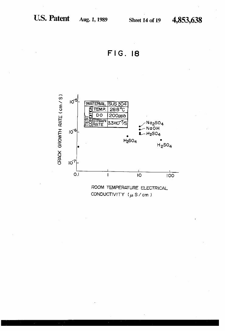
high temperature electrical conductivity and corrosion rate which forms the basis of the present invention; FIG. 18 is a graph showing a correlation between the
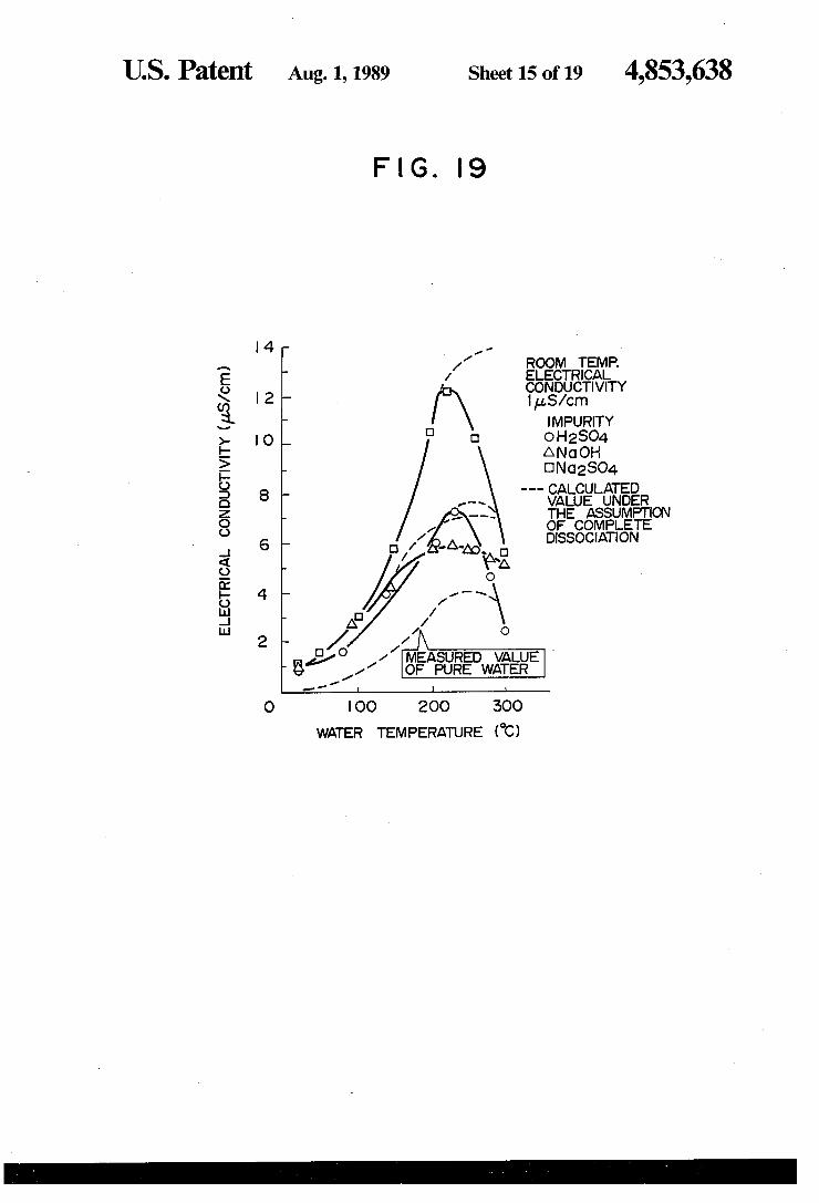
room temperature electrical conductivity and the cor rosion rate known in the art; FIGS. 19 and 20 are graphs respectively showing
comparisons among three kinds of solute substances of NaOH, H2SO4 and Na2SO4 as to patterns of changes in electrical conductivities with temperature when the room temperature electrical conductivities are constant; FIG. 21 is a graph showing a comparison between an
aqueous NaCl solution and an aqueous H2SO4 solution as to changes in electrical conductivities with tempera ture;
FIG. 22 is a graph showing a high temperature elec trical conductivity of a mixed NaCl and H2SO4 solution at 280 C. as a function of a mixing ratio;

4,853,638 5
FIG. 23 is a diagram showing a modified example when the present invention is applied to high tempera ture water containing a plurality of chlorides; and
FIG. 24 is a schematic diagram showing a modified example when the present invention is applied to opti mum control of high temperature pH in the PWR type nuclear reactor primary system.
DESCRIPTION OF THE PREFERRED EMBODIMENTS
FIG. 1 shows a basic arrangement of components when the present invention is applied to the water quality control of a primary cooling system of a boiling water type nuclear power plant. The components shown in FIG. 1 include a nuclear reactor 1, a coolant recirculation line 2, a reactor water sampling line 3, a high temperature electrical conductivity measuring ap paratus 4, a temperature regulator 5, a pressure control valve 6, a room temperature electrical conductivity measuring apparatus 7, and a data analyzer 8. A basic characteristic feature of the arrangement in FIG. 1 resides in that a plurality of electrical conductivity measuring meters for different temperatures are in stalled on the sampling line of high temperature water, and the water quality is controlled based on a measure ment result of the electrical conductivity at each ten perature, and the room temperature electrical conductivity measuring apparatus is not necessarily required. Furthermore, the water quality control is possible solely by the high temperature electrical con ductivity measuring apparatus which measures at a corrosion environment temperature. However, as shown in FIG. 2, in the case of an impu
rity such as H2SO4 which forms a multivalent anion (SO42): by dissociation, the extent of dissociation in high temperature water is lowered remarkably, that is, it dissociates incompletely. As a result, the assumption of complete dissociation can not be applied, and it is difficult to evaluate the amount of included impurity, whether it is large or small, based on the high tempera ture electrical conductivity. In other words, in order to evaluate the amount of inclusion of impurity, whether the amount is large or small, it is necessary to evaluate by using as an indicator the electrical conductivity mea sured in a temperature region (a low temperature region equal to or lower than 150 C.) in which the impurity dissociates completely to irons, or the impurity dissoci ates substantially completely. Moreover, it is known that the Clion, among other impurities, accelerates the corrosion peculiarly in high temperature water, and it is necessary to control the concentration of the Cl ion separately from other impurities. For this reason, there is a problem in performing the high temperature water quality control by solely using the high temperature electrical conductivity measuring apparatus in atomic and thermal power plants in which there is the possibil ity of inclusion of the Clion, and it is not practical.
FIG. 3 shows an example of a water quality control system employing the water quality monitoring appara tus shown in FIG. 1. In the system, the high tempera ture electrical conductivity measured at the corrosion environment temperature is compared with a predeter mined control standard value at the corrosion environ ment temperature, and the effect on the corrosion rate of a structural member which is in contact with high temperature water under measurement is evaluated thereby to decide as to whether the operation of the plant is to be continued or stopped. Furthermore, the
10
15
25
30
35
45
50
55
65
6 changes in the electrical conductivities with tempera ture measured at a plurality of different temperatures are analyzed, and the presence or absence of Cl ion (included as NaCl) and the amount of inclusion thereof due to a leak of sea-water in a condenser is analyzed. The concentration of the Cl ion is compared with a control reference value with respect to the magnitude . thereby to decide as to whether the operation of the plant is to be continued or stopped. FIG. 4 shows a high temperature electrical conduc
tivity measuring apparatus required in implementing the present invention. The apparatus includes measuring electrodes 9, a liquid sample under measurement 10, a current/voltage measuring and control unit 11, an AC impedance analyzer 12 for measuring an AC impedance between the measuring electrodes, an applied frequency control unit 13, lead lines 14, and a sample container 15. The AC voltage supplied from the analyzer 12 is ap plied to the measuring electrodes 9 through the current /voltage measuring and control unit 11. The AC cur rent flowing between the measuring electrodes 9 is measured by the current/voltage measuring and control unit 11, and the measured AC current is supplied to gether with an applied voltage signal to the analyzer 12 thereby to obtain a complex impedance.
Next, an applied frequency control method unique to the high temperature electrical conductivity measuring apparatus will be described in detail through a concrete application example of the measuring apparatus. FIGS. 5A and 5B show the results of analysis of the AC impe dance between the measuring electrodes frequency range from 1 Hz to 100 kHz in which the measuring electrodes include a set of two sheets of platinum elec trodes of the same shape and same surface condition fixed with a constant spacing in a range of 2-12 mm. The measuring electrodes are dipped in pure water at respectively 15° C. and 300° C. to measure the AC impedances over a frequency range of 1 Hz-100 K Hz. It was found from the measured results that:
(1) The electrode set can be approximated to an elec trical equivalent circuit shown in FIG. 6 in a whole temperature range from room temperature to 300 C.
(2) The obtained locus forms a part of a semicircular locus calculated from the FIG. 6 and shown in FIG. 7.
(3) However, the changes in the electrode surface reaction resistance Rf and the electrode capacitance C with temperature, which are directly attributable to the electrode surface reaction, are large as shown in FIG. 8, and the frequency required to directly measure the liquid resistance Rs goes higher as the temperature rises. These results also indicate that the AC signal at a
constant frequency of around 10 kHz used in the con ventional measurement of the room temperature electri cal conductivity is insufficient for the measurement of the liquid resistance Rs at high temperatures. On the other hand, the measurement in a high frequency region equal to 100 kHz or higher imposes the problem in the two points. In other words, there is a significant in crease in impedance, i.e., in noises caused by capacitive and inductive components of the lead lines between the measuring electrode set and the measuring apparatus, and furthermore, the frequency dependency of the liq uid resistance becomes unnegligible. The inventors paid attention to the fact that the locus of the measured impe dance can be approximated on the complex plane by a substantially ideal semicircle or a part of the semicircle, and noticed that the impedance as ca)=0 and at a) = co can be estimated with a sufficient accuracy from a part

4,853,638 7
of the locus by using the applied frequency control unit 13 in FIG. 4. Specifically, FIG. 9 shows a control pro cess performed in the applied frequency control unit 13 in FIG. 4.
First, the frequency is swept from higher to lower frequencies sequentially. A value of the imaginary part of a complex impedance at each frequency is sequen tially compared with the measured value of the previ ous time, and the sweeping of the frequency is stopped at a time point at which it is confirmed that the absolute value of the imaginary part exhibits a maximum value. Supposing that the maximum value is Im(Z)lmax, and the value of the real part at this time point is Re(Z)0, and a measuring frequency is comax, a liquid resistance Rs can be obtained from the following formula.
FIG. 10 shows a comparison between a change in the electrical conductivity of pure water with temperature measured according to the method of the present inven tion and that resulting from the theoretical calculation based on the dissociation of water. Both the measured and theoretical values are coincident with an error of 5%, and the validity of the above-mentioned measur
ing technique could be confirmed. FIG. 11 shows another high temperature electrical
conductivity measuring apparatus required in imple menting the present invention. The AC voltage sup plied from an analyzer 12 is applied across electrodes 9a and 9b (electrode pair X) through a current/voltage measuring and control unit 11. The AC current flowing between the electrodes 9a and 9b is measured by the current/voltage measuring and control unit 11, and the measured result is supplied together with an applied voltage signal to the analyzer 12 thereby to obtain a complex impedance. Then the electrode 9a is changed over to an electrode 9c by a change-over switch 20, and a complex impedance between the electrodes 9c and 9b (electrode pair Y) is obtained in a similar manner. A calculation device 19 calculates a liquid resistance or an electrical conductivity from the result of measurement of both the complex impedances of the electrode pairs X and Y. FIG. 12 shows an electrode structure used in the
measuring apparatus in detail. Three sheets of electrode plates 9a, 9b and 9c are arranged in parallel to one an other, and the electrode pairs X and Y are arranged so that the electrode surface reaction resistances of both pairs are equal to each other. In order to achieve this, for example, opposite surfaces of the central electrode plate 9b are made electrochemically in substantially the same surface condition to exhibit equivalent electro chemical properties. Also, the surface of each of the electrode plates 9a and 9c positioned at opposite sides, which surface facing the central electrode plate 9b, is formed to exhibit substantially the same electrochemi cal property. In addition, the intervals in respective electrode pairs X and Y are arranged to be different from each other, that is, the interval between the elec trode plates 9a and 9b differs from the interval between the electrode plates 9b and 9c. In this respect, in the present invention, the two pairs of electrode plates may be formed with four sheets of electrode plates (not shown). FIG. 6 shows the electrical equivalent circuit between the electrodes when the electrode pair is dipped in water. FIG. 7 shows the frequency response of the complex impedance plotted on the complex plane. The frequency response is calculated by using the
10
15
20
25
30
35
45
50
55
65
8 AC impedance between the electrodes obtained from the equivalent circuit of FIG. 6 and by setting numeri cal values of the AC impedances in the frequency range from zero frequency to substantially infinite frequency. From FIG. 7, a solution resistive component is deter mined from the measured value in a higher frequency range, and the sum of a surface reaction resistance (Rf) and a solution resistance (Rs) is determined from the measured value in a lower frequency range.
FIG. 13 shows the result of measurement of the fre quency response of impedance when three sheets of platinum plates are used as electrode plates. Each of the platinum plates has a size of 25 mm X50 mm and a thick ness of 1 mm, and the surface condition (ground condi tion) of the opposite surfaces of each platinum plate is equivalent, and the interval in the electrode pair X is 5 mm and the interval in the electrode pair Y is set to be 3 mm. When the electrical conductivity is equal to 5 us/cm or larger, even when the AC impedance is mea sured at the maximum frequency of 100 kHz acceptable in the measurement, the semicircular locus as shown in FIG. 7 can not be obtained. Thus, it is difficult to deter mine the solution resistive component from the mea sured values in the higher frequency region with high accuracy. In contrast, the value of 2Rf--Rs can be determined accurately from the measured values in the lower frequency region. Supposing that the value of 2Rf--Rs1 between the electrodes having the electrode interval (L1) of 5 mm is Z1, and the value of 2Rf--Rs2 between the electrodes having the electrode interval (L2) of 3 mm is Z2, the specific electrical conductivity (k) of the liquid is obtained from the following formula.
(Rs.1 - Rs2)/(Li - L.2) (1)
Furthermore, in the present invention, when the elec trode interval is unknown, the value of (L1-L2) can be estimated as follow. Namely, since a difference between Z1 and Z2 is proportional to a reciprocal number of the electrical conductivity, it is possible to convert to the electrical conductivity by obtaining the value of (L1-L2) (proportional constant of the electrodes) from the measurement of a liquid whose electrical conductiv ity is known.
In the present invention, the effect of the polarization occurring on the electrode surface which affects the result of measurement adversely can be neglected by applying an AC voltage at a frequency equal to 10 Hz or higher. Thus, the dependency of measured impe dance on the current density can be suppressed to a great extent.
FIG. 14 shows a correlation between a value of 1/Rs obtained by the method of the present invention and a room temperature electrical conductivity measured by an electrical conductivity measuring apparatus on the market, wherein the room temperature electrical con ductivity is changed in a range from 0.8 to 8pS/cm. A satisfactory linear relation is recognized between both the values, and the validity of the measuring technique in the present invention was confirmed.
In the embodiment described above, the same voltage is applied to the electrode pairs X and Y, and the fre

4,853,638 9
quency of 10 Hz is used as a lowest frequency. How ever, a low frequency alternating current of a frequency lower than 10 Hz may be used. However, if a load frequency alternating current of a frequency equal to 1 Hz or lower is used, the obtained value of 2Rf--Rs will be changed depending on the current density of a cur rent flowing between the electrodes (Rf is changed depending on the current density). Accordingly, it is necessary to adjust the voltages respectively applied to the electrode pairs X and Y, so that the current densities in the electrode pairs X and Y are equal to each other. Furthermore, in embodiment, the measuring electrode set of a three-electrode structure of fixed type is used. However, similar effects will be obtained by using a measuring electrode set of a two-electrode structure with the electrode interval variable in two stages or Oe.
In the embodiment, the parallel, flat plate type elec trodes are used. However, electrodes of a coaxial cylin drical type having equal lengths in the axial direction and having different radiuses may be used to obtain similar effects. When a solute impurity (or an impurity solved and
held in a solution) dissociates completely also in high temperature water, the high temperature electrical con ductivity can be obtained analytically by the following well-known method based on the concentration of the solute impurity. Thus, the high temperature electrical conductivity measuring apparatus described in the fore going becomes unnecessary. Specifically, as ionic spe cies in reactor water, there exist H and OH formed by ionization of the water, besides A and B formed by ionization of an impurity having a schematic chemi cal form represented by A-B and leaked into the reactor water. Supposing that, the molarity of each ionic spe cies is Ci (mol/m), and the equivalent ionic electrical conductivity is Ai (S-m/mol), the electrical conductiv ity K (S/n) is expressed by the following formula.
K=XCi-Ni (5) The molarity of each ionic species can obtained by calculation from the following two conditional formu lae (6) and (7), if the initial amount of addition is deter mined. That is, the conditional formula (6) for electrical neutrality of each ionic species in the solution;
CA. --CH=CB -- Cot (6), and the conditional formula (7) for ionization equilibrium;
CH-CoH =K (7)
(here, K is the ionic product). In molarity can be ob tained from the simultaneous formulae (6) and (7). On the other hand, with respect to the equivalent ionic electrical conductivity, the calculated values in the infinite dilution condition as shown in FIG. 17 are re ported. FIG. 18 shows a comparison between the calcu lated values as to Na2SO4 using the values in FIG. 17 and actually measured values. In the past, Na2SO4 had been considered to dissociate completely in high tem perature water as a strong electrolyte substance. How ever, it was revealed from the experimental results shown in FIG. 18 that the formula for calculating the electrical conductivity on the premise of complete dis sociation is applicable only on the condition that the room temperature electrical conductivity is equal to 1 uS/cm or smaller and the water temperature is equal to 200 C. or lower, and that when the water temperature is equal to 200 C. or higher, the electrical conductivity
10
15
20
25
30
35
45
50
55
65
10 exhibits a value which differs considerably from the high temperature electrical conductivity which had been predicted till then from the calculation.
FIG. 17 shows a correlation between the stress corro sion crack growth rate of stainless steel (SUS 304) which has been subject to sensibility treatment and the high temperature electrical conductivity. The correla tion shown in FIG. 17, that is, the high temperature electrical conductivity at a corrosive environment tem perature measured by using the high temperature elec trical conductivity measuring apparatus is applied to the evaluation of the stress corrosion cracking environ ment. It is confirmed that the stress corrosion crack growth rate is not dependent upon the chemical form of the impurity, but increases in proportion to power of the high temperature electrical conductivity. Accord ingly, the degree of influence of the electrical conduc tivity on the stress corrosion cracking phenomenon can be evaluated quantitatively, and the rational water qual ity control corresponding to the operation history of the plant can be realized.
Next, for the purpose of comparison, the correlation between the stress corrosion crack growth rate and the room temperature electrical conductivity known in the art is shown in FIG. 18. However, since the correlation is not satisfactory, it is difficult to accurately evaluate the stress corrosion cracking environment based on the room temperature electrical conductivity. For this rea son, in order to achieve the control with sufficient mar gin with respect to the safety, in the case of the water quality control based on the room temperature electri cal conductivity, the water quality control standard value must be set more severely than it is necessary.
Hereinafter, a method of determination of a solute substance which is unique in the present invention will be described by way of concrete examples showing the application of the method. FIGS. 19 and 20 show the results obtained experimentally as to the correlation between a variation in room temperature electrical con ductivity and a variation in high temperature electrical conductivity as to the three kinds of solute impurities; NaOH, H2SO4 and Na2SO4. Specifically, a change in electrical conductivity of aqueous solution with temper ature is shown for each of the three kinds of impurities in contrast to one another, wherein imitatively, the three kinds of impurities are respectively dissolved in pure water having a room temperature electrical con ductivity of 0.1 uS/cm, and the room temperature elec trical conductivity of the solution is adjusted to 1 uS/cm (in FIG. 19) and 9.5 S/cm (in FIG.20). As will be seen from FIGS. 19 and 20, although the room tem perature electrical conductivity is the same, the change in electrical conductivity with temperature exhibits a pattern peculiar to each of the impurities, and in particu lar, in a temperature range of 150-250 C., the differ ences among the solute substances become significant. Accordingly, by measuring an increase in the room temperature electrical conductivity for pure water, and by using the results shown in FIGS. 19 and 20, for example, the amount of increase in the high temperature electrical conductivity at 200 C. is predicted for each of the three kinds of solute impurities; NaOH, H2SO4 and Na2SO4. Then, by comparing the predicted results with actually measured values of the increase in the high temperature electrical conductivity, it is possible to determine the kinds of the solute substances con tained in the core water. Once the kinds of the solute

4,853,638 11
substances have been determined, it is possible to fur ther analyze the concentrations of the solute substances based on the value of the room temperature electrical conductivity.
EMBODIMENT 2.
In the embodiment described above, in predicting the amount of increase in the high temperature electrical conductivity, the actually measured data relating to the change in electrical conductivity with temperature ob tained when the room temperature electrical conductiv ity is made to change for each kind of solute substance is used as it is. However, when the room temperature electrical conductivity is equal to 1 S/cm or less and the water temperature is equal to 200 C. or lower, it is possible to obtain the amount of increase in the high temperature electrical conductivity analytically by using the following method known in the art. When the room temperature electrical conductivity of a sample under measurement exceeds 1 uS/cm, pure water for dilution can be supplied at the upstream side of the electrical conductivity measuring apparatus so that the room temperature electrical conductivity decreases to 1 uS/cm or less.
EMBOOMENT 3
In the embodiment 2, in order to apply the present invention to the analysis of an aqueous solution having a room temperature electrical conductivity equal to 1 LS/cm or larger, a dilution device is provided at the upstream side of the high temperature electrical con ductivity measuring apparatus. However, when the high temperature electrical conductivity of each kind of solute substance is known, whose room temperature electrical conductivity is close to the room temperature electrical conductivity of an aqueous solution under measurement, it is possible to know the high tempera ture electric conductivity of the aqueous solution under measurement approximately by the following method. That is, a change in electrical conductivity with temper ature when the room temperature electrical conductiv ity is A S/cm (A > 1), is obtained experimentally for each of NaOH, H2SO4 and Na2SO4, and the obtained values are expressed respectively as a function of tem perature (T) by finaOH (T), fESO4 (T) and fNa2SO4 (T). Supposing that the room temperature electrical conduc tivity C S/cm of the aqueous solution under measure ment is changed from C S/cm to C-AC S/cm by AC S/cm, the amounts of change AfnaoH (To), Aft2SO4 (To) and Afna2SO4 (To) of the high temperature electrical conductivity at a temperature To can be ob tained from the following formulae (8)-(10).
AfNaOH (To) = AC X (A - Ao)
Aft2SO4 (To) = AC X (A - 40)
(fNa2SO4 (To) - fo (To)} (10) AfNa2SO4 (To) = AC X - -
where, A0 is a value of the electrical conductivity of pure water at room temperature, and fo(To) is a value of the electrical conductivity of pure water at a tempera ture To. Furthermore, in order to enhance the accuracy
O
5
20
25
30
35
45
50
55
60
65
12 of approximation, ACs (A-Ao) is a necessary condi tion. By comparing the values of
AfNaOH (To), AfthsO4 (To), and AfNa2SO4
estimated by the above formulae with actually mea sured values, it is possible to directly determine a solute substance in an aqueous solution whose electrical con ductivity is equal to 1 S/cm or larger without deluting the solute substance.
EMBODIMENT 4
In the above embodiments, the object solute sub stances to be determined are NaOH, H2SO4 and Na2 SO4. However, the present invention can be applied by a similar technique to aqueous solutions containing other electrolyte substances. When the reactor water of a nuclear reactor is the
object of measurement, the substances which are highly possible to be included in the reactor water are the following two kinds of substances. One is NaCl in cluded due to leakage of sea water in the condenser, and the other is H2SO4 produced by thermal decomposition of ion exchange resin which flows into a core section from a condensating and desalting device where the ion exchange resin is used.
In order to control the concentration of Clion which has a peculiar acceleration effect on the corrosion in high water temperature, the temperature dependency of the electrical conductivity is measured in a range from a corrosive environment temperature to a room temper ature. By utilizing the fact that such a temperature de pendency exhibits a pattern inherent in a chemical form of the impurity, the chemical form of the impurity, in particular, the presence or absence of Clion is decided.
FIG. 21 shows a comparison between changes in electrical conductivity with temperature in both aque ous solutions (room temperature electrical conductivity of 10 S/cm) of NaCl and H2SO4. As shown in FIGS. 19 and 20, even when the room
temperature electrical conductivity is the same, the high temperature electrical conductivities differ from each other depending on the chemical forms of the solute substances. In particular, when NaCl and H2SO4 are compared with each other, the difference between the high temperature electrical conductivities of both substances becomes significant in a high temperature region equal to 200 C. or higher in which H2SO4 does not dissociate completely. Thus, it is impossible to de termine whether the solute substance is NaCl or H2SO4 by comparing a measured temperature dependency of electrical conductivity with the result shown in FIG. 21. In the embodiment, the chemical form of the impu rity is determined by comparing the patterns of the temperature dependency of electrical conductivity with each other. However, it is possible to determine based on the amount of change in the electrical conductivity at two different temperatures. For example, by compar ing the amount of change between a room temperature electrical conductivity and a high temperature electri cal conductivity at 280 C. with the result shown in FIG. 21, it is possible to determine whether the impu rity is NaCl or H2SO4. Furthermore, when NaCl and H2SO4 coexist, as shown in FIG. 22, the contribution rate of NaCl to the room temperature electrical conduc tivity increases, the value of the high temperature elec trical conductivity at 280 C. increases from a value of an aqueous H2SO4 solution to a value of an aqueous
4,853,638 13
NaCl solution substantially linearly. Accordingly, it is possible to quantitatively determine a mixing ratio of NaCl and H2SO4.
EMBODIMENT 5
When other chlorides are coexisting other than NaCl, as shown in FIG. 23 a heat-resisting cation exchange body 22 is provided at the upstream side of a high tem perature electrical conductivity meter 4, and all the chlorides are converted in the form of HC. Accord ingly, the concentration of Cl ion can be determined quantitatively. For example, as the heat-resisting cation exchange body 22, iron oxide (Fe3O4) is used, and when high temperature water at 280 C. and including HCl, KC, and CoCl2 other than NaCl is fed through a col umn filled with the iron oxide, the Nat, Kh and Co2 ions are replaced by H ions on the surface of the iron oxide. As a result, the cation component in the water in the outlet of the column includes only Hi ion, and the anion component in the water includes only Clt ion. Accordingly, the temperature dependency of electrical conductivity of the aqueous HCl solution is obtained in advance, and by comparing the temperature depen dency in the aqueous HCl solution with the temperature dependency of electrical conductivity exhibited by the water in the outlet of the column, it is possible to decide the presence or absence of the Clion. Furthermore, the concentration of the Clion can be determined quantita tively from the electrical conductivity at room tempera ture at which HCl dissociates to ions completely.
EMBODIMENT 6
FIG. 24 illustrates an embodiment in which the pres ent invention is applied to optimum control of pH of high temperature water in a primary cooling system of a power water type atomic plant (hereinafter referred to as PWR). In FIG. 24, reference numeral 23 designates a nuclear reactor, 24 a water vapor generator, 25 a pri mary system high temperature water sampling line, 26 a dissociation evaluation device of boric acid, 27 a high temperature pH evaluation device, and 28 an LiOH concentration regulating device. In the high tempera ture water in the PWR primary system, the boric acid is added to control the degree of reaction. The concentra tion of the boric acid is lowered with the progress of operation of the plant. On the other hand, in order to suppress a decrease of pH due to the addition of the boric acid, LiOH is added, and the concentration of LiOH is controlled so that pH at high temperatures assumes an optimum value (around 7) from the stand point of suppressing the corrosion. However, pH at the corrosive environment temperature is not directly mea sured, and the control is performed based on high tem perature pH calculated from measured values of boric acid and LiOH concentrations, and based on high tem perature pH calculated from the dissociation of an aque ous boric acid solution. However, generally, since the dissociation of electrolyte is influenced by solvent and other coexisting electrolytes, more accurate optimum control of high temperature pH is possible by using the extent of dissociation of boric acid in high temperature water in which LiOH and boric acid coexist.
In the present invention, in order to realize the two types of control method above, firstly, as shown in FIG. 24, a high temperature electrical conductivity in high temperature water at a corrosive environment tempera ture is measured. From the measured result, the extent of dissociation of boric acid at the corrosive environ
10
15
20
25
30
35
40
45
50
55
65
14 ment temperature is determined. In other words, since LiOH dissociates to ions almost completely even in high temperature water, the electrical conductivity of high temperature water in which boric acid and LiOH coexist can be calculated as a function of the extent of dissociation of the boric acid. On the other hand, from the actually measured value of the high temperature electric conductivity, it is possible to determine the extent of dissociation of boric acid in a corrosive envi ronment when LiOH coexists. In calculating the electri cal conductivity mentioned above, although the con centrations of boric acid and LiOH are necessary, these concentrations can be obtained in the following manner from a measured value of the electrical conductivity in a temperature region in which boric acid dissociates almost completely, for example, at a room temperature. Specifically, by supplying high temperature water to a cation exchange body, the boric acid concentration can be obtained from a room temperature electrical conduc tivity of sampling water in which LiOH has been re moved. Furthermore, the LiOH concentration can be obtained from a difference between a room temperature electrical conductivity of sampling water which is not supplied to the cation exchange body and a room tem perature electrical conductivity of sampling water in which LiOH has been removed by passing through the cation exchange body. The concentrations of boric acid and LiOH obtained by in-line measurement of the elec tric conductivity in a temperature range from the corro sive environment temperature to the room temperature, and the extent of dissociation of boric acid at the corro sive environment temperature are used to calculate a concentration of hydrogen at the corrosive environ ment temperature, that is, high temperature pH is ob tained. The calculated high temperature pH is com pared with an optimum control value of high tempera ture pH to determine which is larger, and when pH is larger than the optimum control value, the LiOH con centration is reduced. Conversely, when pH is smaller than the optimum control value, the LiOH concentra tion is increased. In this manner, the LiOH concentra tion regulating device is controlled, and it is possible to maintain pH at an optimum value. As described above, the in-line analysis of the con
centrations of boric acid and LiOH can be achieved, and at the same time, the high temperature pH control which is accurate and quick in response, and which takes the extent of dissociation of boric acid at the cor rosive environment temperature into consideration can be realized easily.
In the above embodiment, there is shown an example of application of the present invention to the evaluation of high temperature pH in a mixed aqueous solution of boric acid and LiOH. However, the present invention is not limited to such a combination but is generally appli cable to the evaluation of high temperature pH in a mixed aqueous solution containing a plurality of elec trolytes.
In the present invention, it is possible to perform the water quality control by accurately measuring the elec trical conductivity of an aqueous solution even when the aqueous solution is in a relatively high temperature region equal to or higher than room temperature in which the solute substance does not dissociate com pletely.
Furthermore, by analyzing the corrosion rate and the concentration of corrosive anion by using an electrical conductivity measuring apparatus, it is possible to easily

4,853,638 15
realize the water quality control which takes into con sideration a difference in the influence on the corrosion due to a chemical form of a solute substance in high temperature water, in particular, in a temperature re gion in which the solute substance dissociates incom pletely. In addition, since the water quality control standard value is set for each chemical form of the solute substances individually, it is possible to rationally moderate the water quality control standard value used at the present time which is excessively severe, without degrading the safety in the water quality control. We claim: 1. A method of water quality control comprising the
steps of: (a) measuring electrical conductivities of an aqueous
solution under measurement at least at a tempera ture To and a temperature Tn, and obtaining a relationship between the electrical conductivity and the temperature, wherein the measurement temperature To is in a first range, and the measure ment temperature Tn is in a second range different from said first range, and at least one value of the electrical conductivity is measured in each of the temperature ranges;
(b) utilizing a determining means to determine a sol ute substance in said aqueous solution under mea surement by applying the relationship obtained in said step (a) to a relationship between a tempera ture and an electrical conductivity of an individual substance obtained beforehand; and
(c) utilizing an estimating means to estimate a concen tration of the substance determined in said step (b) by applying the electrical conductivity at a lowest temperature To among the measurement tempera tures in said first temperature range in said step (a) to a relationship between an electrical conductivity and a concentration at the same temperature To with respect to an individual substance obtained beforehand.
2. A method according to claim 1, wherein said first range is from a predetermined temperature up to 100 C., and said second range is from 150 to 280 C.
3. A method of measuring an electrical conductivity of an aqueous solution comprising the steps of:
(A) immersing at least a pair of electrodes in said aqueous solution under measurement in order to obtain a relationship between an electrical conduc tivity and a temperature by measuring electrical conductivities at least at two different temperatures To and Tn with respect to said aqueous solution under measurement, and measuring a complex AC impedance between said pair of electrodes at each of the temperatures of said aqueous solution by applying an AC voltage between said pair of elec trodes while varying a frequency of the AC volt age, wherein the measurement temperature To is in a first range, and the measurement temperature Tn is in a second range different from said first range, and at least one value of the electrical conductivity is measured in each of the temperature ranges;
(B) obtaining a liquid resistance of said aqueous solu tion under measurement at each of the measure ment temperatures from a frequency response of each of the complex impedance;
(C) obtaining an electrical conductivity at each of the measurement temperatures from said liquid resis tance;
10
15
20
25
30
35
45
50
55
65
16 (D) determining a solute substance in said aqueous
solution under measurement by applying a relation ship between the measurement temperatures and the electrical conductivities to a relationship be tween a temperature and an electrical conductivity with respect to an individual substance; and
(e) estimating a concentration of the solute substance determined in said step (D) by applying the rela tionship between a lowest temperature To in said first temperature range and the electrical conduc tivity obtained in said step (C) to a relationship between the same temperature To and a concentra tion with respect to an individual substance ob tained beforehand
4. A method according to claim 3 wherein, in said steps (A) and (B), said liquid resistance is obtained by using a pair of electrodes, detecting a maximum value of absolute values of imaginary parts of said complex AC impedances between said pair of electrodes, obtaining an electrode surface reaction resistance value of said electrodes from the maximum value, and subtracting the maximum value of the absolute values of the imagi nary parts from a real part of the complex AC impe dance corresponding to said maximum value.
5. A method according to claim 3 wherein, in said steps (A) and (B), said liquid resistance is obtained by immersing two measuring electrode pairs X and Y
into said aqueous solution, said two measuring electrode pairs X and Y respectively having elec trode intervals different from each other and hav ing substantially identical electrochemical, elec trode surface reaction resistances,
measuring the complex AC impedances between the electrodes of said electrode pair X by applying the AC voltage between said electrodes while chang ing a frequency thereof,
measuring the complex AC impedances between the electrodes of said electrode pair Y by applying the AC voltage between said electrodes while chang ing a frequency thereof,
detecting a minimum value of absolute values of imaginary parts of the complex AC impedances between the electrodes of said electrode pair X, said minimum value being in a frequency range close to a DC side of said AC voltage, and obtain ing from said minimum value a combined resis tance consisting of an electrode surface reaction resistance and a liquid resistance between the elec trodes of said electrode pair X,
detecting a minimum value of absolute values of imaginary parts of the complex AC impedances between the electrodes of said electrode pair Y, said minimum value being in a frequency range close to a DC side of said AC voltage, and obtain ing from said minimum value a combined resis tance consisting of an electrode surface reaction resistance and a liquid resistance between the elec trodes of said electrode pair Y,
obtaining the liquid resistance of said aqueous solu tion from a difference between the combined resis tances of said electrode pair X and said electrode pair Y, and
obtaining the electrical conductivity of said aqueous solution from said liquid resistance.
6. A method according to claim 5 wherein the applied frequencies are in a range of 10-100 Hz.
4,853,638 measuring the complex AC impedances between the
17 7. A method according to claim 3, wherein said first
range is from a predetermined temperature up to 100 C., and said second range is from 150 to 280 C.
8. A method of water quality control for analyzing a corrosive substance in an aqueous solution with a metal- 5 lic structural member dipped therein, and for detecting a corrosion rate of said metallic structural member, said method comprising the steps of:
18
electrodes of said electrode pair X by applying the AC voltage while changing the frequency thereof,
measuring the complex AC impedances between the electrodes of said electrode pair Y by applying the AC voltage while changing the frequency thereof,
detecting a minimum value of absolute values of imaginary parts of the complex AC impedances
(A) immersing at least a pair of electrodes in an aque ous solution under measurement in order to obtain a relationship between an electrical conductivity and a temperature by measuring electrical conduc tivities at least at two different temperatures To and Tn with respect to said aqueous solution under measurement, and measuring a complex AC impe dance of said aqueous solution between said pair of electrodes at each of the measurement tempera tures by applying an AC voltage between said pair of electrodes while varying a frequency thereof;
(B) obtaining a liquid resistance of said aqueous solu tion under measurement at each of the measure ment temperatures from a frequency response of each complex AC impedance;
(C) obtaining an electrical conductivity at each of the measurement temperatures from said liquid resis tance;
(D) deciding a corrosion rate of said metallic struc tural member in contact with said aqueous solution by applying a relationship between a maximum temperature in the measurement temperatures and the electrical conductivity to a relationship be tween an electrical conductivity and a corrosion rate of an individual substance obtained before hand;
(E) determining a solute substance in said aqueous solution under measurement by applying the rela tionship between the measurement temperatures and the electrical conductivity to a relationship between a temperature and an electrical conductiv ity of an individual substance obtained beforehand; and
(F) with respect to the determined substance, estimat ing a concentration of said substance by applying a part of the relationship obtained in said step (C), that is, the relationship between the temperature and the electrical conductivity at a lowest tempera ture To, to a relationship between an electrical conductivity and a concentration at the same tem perature To with respect to an individual substance obtained beforehand.
9. A method according to claim 8 wherein, in said
10
15
20
25
30
35
45
50
between said electrode pair X, said minimum value being in a frequency range close to a DC side of said AC voltage, and obtaining from said minimum value a combined resistance consisting of an elec trode surface reaction resistance and a liquid resis tance between the electrodes of said electrode pair X,
detecting a minimum value of absolute values of imaginary parts of the complex AC impedances between said electrode pair Y, said minimum value being in a frequency range close to a DC side of said AC voltage, and obtaining from said minimum value a combined resistance consisting of an elec trode surface reaction resistance and a liquid resis tance between the electrodes of said electrode pair Y,
obtaining the liquid resistance of aid aqueous solution from a difference between the combined resis tances of said electrode pair X and said electrode pair Y, and
obtaining the electrical conductivity of said aqueous solution from said liquid resistance.
11. A method according to claim 10 wherein the applied frequency are in a range of 10-100 Hz.
12. A method according to claim 8, wherein To is in a range from a predetermined temperature up to 100 C., and Tn is in a second range from 150 to 280 C.
13. An apparatus for measuring an electrical conduc tivity of an aqueous solution by applying an AC voltage between measuring electrodes which are dipped in said aqueous solution containing ions, and measuring at least one of an electrode surface reaction resistance and a liquid resistance of said aqueous solution, said apparatus comprising:
a plurality of electrode pairs having respective elec trode intervals different from each other and hav ing substantially identical electrochemical, elec trode surface reaction resistances;
means for measuring AC complex impedances be tween the electrodes of each said electrode pair by applying the AC voltage between said electrodes while changing a frequency thereof:
means for detecting a minimum value of absolute steps (A) and (B), said liquid resistance is obtained by using a pair of electrodes, detecting a maximum value of absolute values of imaginary parts of said complex AC impedances, obtaining an electrode surface reaction 55 resistance value of said electrodes from the maximum value, and subtracting the maximum value of the abso lute values of the imaginary parts from a real part of the complex AC impedance corresponding to said maxi mum value. 60
10. A method according to claim 8 wherein, in said steps (A) and (B), said liquid resistance is obtained by
immersing two measuring electrode pairs X and Y into said aqueous solution, said two measuring electrode pairs X and Y respectively having elec- 65 trode intervals different from each other and hav ing substantially identical electrode surface reac tion resistances,
values of imaginary parts of the complex AC im pedances between the electrodes of each said elec trode pair, said minimum value being in a fre quency range close to a DC side of said AC volt age, and for obtaining from said minimum value a combined resistance consisting of an electrode surface reaction resistance and a liquid resistance between the electrodes of each said electrode pair;
first means for obtaining the liquid resistance of said aqueous solution from a difference between the combined resistances of each said electrode pair; and
second means for obtaining the electrical conductiv ity of said aqueous solution from said liquid resis tance.
14. A method of water quality control for analyzing a corrosive substance in an aqueous solution with a metal
4,853,638 20
between the electrodes of said electrode pair Y, said minimum value being in a frequency range close to a DC side of said AC voltage, and obtain
19 lic structural member dipped therein, and for detecting a corrosion rate of said metallic structural member, said method comprising the steps of: (A) immersing at least a pair of electrodes in said aqueous solution under measurement in order to 5 tance consisting of an electrode surface reaction obtain a relationship between an electrical conduc- resistance and a liquid resistance between the elec tivity and a temperature by measuring electrical trodes of said electrode pair Y, conductivities at least at a temperature To in a first obtaining the liquid resistance of said aqueous solu range and a temperature Tn in a second range dif- tion from a difference between the combined resis ferent from said first range with respect to said 10 tances of said electrode pair X and said electrode aqueous solution between said pair of electrodes at pair Y, and each of the measurement temperatures by applying obtaining the electrical conductivity of said aqueous an AC voltage between said pair of electrodes solution from said liquid resistance; while varying a frequency thereof; (C) obtaining an electrical conductivity at each of the
(B) obtaining a liquid resistance of said aqueous solu- 15 measurement temperatures from said liquid resis tion under measurement at each of the measure- tance; ment temperatures from a frequency response of (D) deciding a corrosion rate of said metallic struc each of the complex AC impedances, wherein said tural member in contact with said aqueous solution liquid resistance is obtained by, by applying a relationship between a maximum
immersing two measuring electrode pairs X and Y 20 temperature in the measurement temperatures and into said aqueous solution, said two measuring the electrical conductivity to a relationship be electrode pairs X and Y respectively having elec- tween an electrical conductivity and a corrosion trode intervals different from each other and hav- rate of an individual substance obtained before ing substantially identical electrochemical, elec- hand; trode surface reaction resistances, 25 (E) determining a solute substance in said aqueous
measuring the complex AC impedances between the solution under measurement by applying the rela electrodes of said electrode pair Xby applying the tionship between the measurement temperature AC voltage between said electrode while changing and the electrical conductivity to a relationship a frequency thereof, between a temperature and an electrical conductiv
measuring the complex AC impedances between the 30 ity of an individual substance obtained beforehand; electrodes of said electrode pair Y by applying the and AC votlage between said electrodes while chang- (F) with respect to the determined substance, estimat ing a frequency thereof, ing a concentration of said substance by applying a
detecting a minimum value of absolute values of part of the relationship obtained in said step (C), imaginary parts of the complex AC impedances 35 that is, the relationship between the temperature between the electrodes of said electrode pair X, and the electrical conductivity at a lowest tempera said minimum value being in a frequency range ture To, to a relationship between an electrical close to a DC side of said AC voltage, and obtain- conductivity and a concentration at the same tem ing from said minimum value a combined resis- perature To with respect to an individual substance tance consisting of an electrode surface reaction 40 obtained beforehand. resistance and a liquid resistance between the elec- 15. A method according to claim 14, wherein said trodes of said electrode pair X, first range is from a predetermined temperature up to
detecting a minimum value of absolute values of 100 C., and said second range is from 150 to 280 C. imaginary parts of the complex AC impedances is it k . .
45
50
55
60
65
ing from said minimum value a combined resis