Embed Size (px)
Citation preview
University of Connecticut Senior Design BME4900
Final Report Automatic Lift System for Danielle Giroux
Team 5
Jordan Smith
Kayla Gosse
Leah McElhaney
Client Contact Information:
Dave and Suzanne Giroux
53 Charlotte Dr, Tolland, CT 06084
860-604-0893
1
Table of Contents
Abstract……………………………………………………………………………………………2
1. Introduction…………..………………………………………………………….. ……………..3
1.1 Background……………………………………………………………………………3
1.2 Purpose of Project……………………………………………………………………..4
1.3 Previous Work Done by Others…………………………………………………….…4
1.3.1 Products……………………………………………………………………...4
1.3.2 Patents……………………………………………………………………….4
1.4 Map for the Remainder of the Report…………………………………………………5
2. Project Design…………………………………………………………………………………..6
2.1 Introduction……………………………………………………………………………6
2.1.1. Alternative Design 1………………………………………………………..6
2.1.2. Alternative Design 2………………………………………………………..7
2.1.3. Alternative Design 3………………………………………………………..8
2.2 Optimal Design………………………………………………………………………10
2.2.1 Objective…………………………………………………………………...10
2.2.2 Subunits……………………………………………………………………12
2.2.2.1 Motorized Jacks and Battery……………………………………..12
2.2.2.2 Platform…………………………………………………………..12
2.2.2.3 Base Assembly…………………………………………….……..13
2.2.2.4 Foldable Ramp……………………………………………….…..15
2.2.2.4.1 Ramp Components……………………………………..15
2.2.2.4.2 Latch/Hinge to Secure Components……………...……17
2.2.2.4.3 Support Rods…………………………………….……..17
2.2.2.4.4 Attachment to Lift……………………………….……..20
2.2.2.5 Threshold Ramp…………………………………………...……..20
3. Realistic Constraints……………………………………………………………………..……21
4. Safety Issues…………………………………………………………………………...………23
5. Impact of Engineering Solutions…………………………………………………...…………24
6. Life-Long Learning……………………………………………………………………………25
7. Budget and Timeline…………………………………………………………………..………25
7.1 Budget………………………………………………………………………………..25
7.2 Timeline……………………………………………………………………………...26
8. Team Member Contribution to Project………………………………………………..………28
9. Conclusion………………………………………………………………………………….…29
10. References……………………………………………………………………………………30
11. Acknowledgements………………………………………………………………………..…31
12. Appendix…………………………………………………………………………………..…32

2
Abstract
The purpose of this project is to develop an automatic ramp to assist Danielle Giroux in
and out of her home, as well as in and out of other locations. Danielle Giroux is an 11 year-old
girl with cerebral palsy. She is confined to a wheel chair and therefore cannot enter or exit
buildings with stairs. Danielle’s home has a front porch with three stairs attached. The automatic
ramp will assist Danielle with getting her wheelchair in and out of her home with minimal
assistance from her family members. Additionally, this automatic ramp will be collapsible and
transportable so that Danielle and her family can bring the ramp to other locations for use, most
importantly other relatives’ homes that are not suited for people with disabilities. Currently
Danielle enters and exits her home only with the help of family members; one family member
will pick Danielle out of her wheel chair and carry her in or out of the home, while a second
family member must carry Danielle’s wheelchair in or out as well. This puts a tremendous strain
on the family because Danielle is getting older and heavier. The wheel chair she currently uses
also is getting bigger as Danielle’s needs change. The project design of the automatic ramp will
eliminate the need for Danielle’s family to physically bring her in and out of her home.
The finished device will be a collapsed lift that will be placed at the bottom of the stairs
Danielle wishes to ascend. The wheelchair will be rolled on top of the lift and secured with ties,
much like the ramp Danielle uses in her family’s van. Once secured, the lift will elevate Danielle
vertically to the desired height of the stairs. Once Danielle is in the correct vertical position, a
second ramp will fold out of the lift mechanism. The ramp will fold out to reach the foyer area at
the top of the stairs. There are four support rods positioned underneath the ramp component.
Once the ramp is positioned at the top of the stairs, the four support rods will fall down onto the
steps for additional support. Once the ramp and support rods are in place, a family member will
undo Danielle’s tie down’s and she will be able to maneuver across the ramp onto the foyer of
the porch. Additionally, a threshold ramp will be used to aid Danielle in and out of the building
itself. All components will be made of aluminum to support Danielle’s weight, as well as the
weight of her wheelchair. The ramp will also be functional in the reverse direction so the patient
may exit the building. The ramp will be controlled by two automatic jacks spaced one foot apart.
The two jacks will each have their own motor; both motors will be attached to one battery, and
the battery will be controlled using a remote control. The two jacks will be wired together so the
user can control both simultaneously using only one remote control. This is critical to the design
because Danielle will not be able to operate the lift system alone, per the request of the client. It
is critical that the ramp will only be automated by the patient’s family members and not the
patient herself to avoid accidental activation or malfunction.
This design project will be created to accommodate homes and buildings with two to four
steps leading to a stoop, as well as the ledge leading from the stoop to the building. This device
is unusual because it must fit a variety of different stoops. The automatic lift will assist the
patient to enter and exit any building of her choice with two to four steps.
3
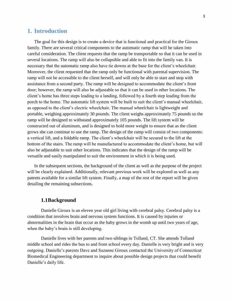
1. Introduction
The goal for this design is to create a device that is functional and practical for the Giroux
family. There are several critical components to the automatic ramp that will be taken into
careful consideration. The client requests that the ramp be transportable so that it can be used in
several locations. The ramp will also be collapsible and able to fit into the family van. It is
necessary that the automatic ramp also have tie downs at the base for the client’s wheelchair.
Moreover, the client requested that the ramp only be functional with parental supervision. The
ramp will not be accessible to the client herself, and will only be able to start and stop with
assistance from a second party. The ramp will be designed to accommodate the client’s front
door; however, the ramp will also be adjustable so that it can be used in other locations. The
client’s home has three steps leading to a landing, followed by a fourth step leading from the
porch to the home. The automatic lift system will be built to suit the client’s manual wheelchair,
as opposed to the client’s electric wheelchair. The manual wheelchair is lightweight and
portable, weighing approximately 30 pounds. The client weighs approximately 75 pounds so the
ramp will be designed to withstand approximately 105 pounds. The lift system will be
constructed out of aluminum, and is designed to hold more weight to ensure that as the client
grows she can continue to use the ramp. The design of the ramp will consist of two components:
a vertical lift, and a foldable ramp. The client’s wheelchair will be secured to the lift at the
bottom of the stairs. The ramp will be manufactured to accommodate the client’s home, but will
also be adjustable to suit other locations. This indicates that the design of the ramp will be
versatile and easily manipulated to suit the environment in which it is being used.
In the subsequent sections, the background of the client as well as the purpose of the project
will be clearly explained. Additionally, relevant previous work will be explored as well as any
patents available for a similar lift system. Finally, a map of the rest of the report will be given
detailing the remaining subsections.
1.1 Background
Danielle Giroux is an eleven year old girl living with cerebral palsy. Cerebral palsy is a
condition that involves brain and nervous system functions. It is caused by injuries or
abnormalities in the brain that occur as the baby grows in the womb up until two years of age,
when the baby’s brain is still developing.
Danielle lives with her parents and two siblings in Tolland, CT. She attends Tolland
middle school and rides the bus to and from school every day. Danielle is very bright and is very
outgoing. Danielle’s parents Dave and Suzanne Giroux contacted the University of Connecticut
Biomedical Engineering department to inquire about possible design projects that could benefit
Danielle’s daily life.

4
Danielle currently has no motor control of her left hand due to her disability. However,
Danielle is not discouraged by her condition. She is eager to work with us and her family to
create a device to assist her in and out of her relatives’ homes, which will expand her social skills
immensely as well as bring a positive outlook on traveling for her and her family, since entering
and exiting a non-handicap accessible building will no longer be an issue.
1.2 Purpose of the Project
Currently Danielle enters and exits her home with help of both parents. On a typical day,
Danielle’s mother Suzanne will carry Danielle in and out of their home, and Danielle’s father
Dave will carry her wheelchair in and out. This puts an enormous strain on both parents as well
as Danielle because she is a growing girl. Soon Danielle’s mother and father will not be able to
lift her and her wheelchair with such ease as they did when she was little.
The automatic ramp that will be designed for Danielle will eliminate the need for her
mother and father to physically remove her and bring her in to her home. Additionally, it will
enable the family to visit various locations that may not be handicap accessible, such as a
relative’s home. The device will enhance Danielle’s independence and make travel much less
stressful for her family.
1.3 Previous Work Done by Others
1.3.1 Products
There are currently no products on the market that fit all the criteria that the client
requested in the design for the automatic lift system. There are, however, several stationary
ramps that could adequately help someone with a similar disability. Collapsible ramps are fairly
affordable and easy to obtain. The Alumilite Folding Curb Ramp is a basic ramp to get up or
down two to four stairs. This ramp, from Alumiramp, Inc., comes in a variety of dimensions: 3,
4, 5, or 6 feet x 29 or 36 inches open, and 15 or 18 inches closed. Depending of what model
purchased, the weight of the Alumilite Folding Curb Ramp varies from 18 to 41 pounds
depending on size. The capacity of this ramp is 600 pounds. A threshold ramp is also suitable to
get the client into her home from the stoop. An Aluminum Wheelchair Threshold Ramp costs
approximately $175.95 and is manufactured by The Express Ramps Network. The threshold
ramp is also transportable and weighs approximately 20 pounds. It can accommodate thresholds
5 3/4" to 6 1/4" tall. The threshold ramp is 32 3/4" in length by 34".
1.3.2 Patent Search Results
The patent that exists for a portable ramp device is owned by Roy T. Witkin of Wesport,
CT. The patent was issued on February 16, 1999. The patent describes the ramp as “a portable

5
ramp for use in allowing access for the disabled, in a wheelchair, to enter an automobile,
elevated area and the like or for similar entry use by a pet.” The patent number is 5870788 and
figure 1. shows the schematic for the device.
Figure 1. Schematic for Patent 5870788
1.4 Map for the Rest of the Report
The remainder of this report will focus on the design of the automatic lift system. Three
alternative designs will be discussed, as well as an optimal design, with subunits included. The
realistic constraints of the design will also be featured, as well as all the safety issues concerning
the device. Furthermore, the impact of engineering solutions will be addressed as well as the
lifelong learning that was obtained from completing this design. The budget will also be outlined
for this project, and a tentative timeline will also be included. In addition, team member
contributions will be noted in the remainder of the report.

6
2. Project Design 2.1 Introduction
The project design involves three alternative designs as well as an optimal design. The
three alternative designs will be briefly discussed in the following subsections, followed by an in
depth discussion of the optimal design. Included in the optimal design discussion will be all the
subunits involved. All designs will be supplemented by pictures, figures, and SolidWorks
adaptations.
The optimal design was chosen by combining different elements of all three alternative
designs. Due to the realistic constraints of the design, the optimal design will be the most
beneficial to the client while still remaining in budget. The optimal meets all specifications set
forth by the client and will be completed on time for the client to take the device on vacation
with them in the Spring.
2.1.1 Alternative Design 1
The first alternative design for the automatic lift system will be in two parts. The first is
the automatic ramp to ascend/descend the stairs. The second part will be the threshold ramp to
get the client in and out of the home. The threshold ramp will not be automated. The design of
this ramp system will enable the client to ascend/descend the stairs and maneuver herself to the
door to gain entry into the home or building.
The automatic portion of the ramp will also be transportable so that the client can use the
device in other locations. The ramp will fold horizontally and close like a suitcase. The ramp will
have a handle on it when closed for easy transport. The ramp will not exceed a width of 8” when
folded to ensure that it will fit in the family van without taking up too much space. Additionally,
there will be tie downs on the automatic portion of the ramp for the client’s wheelchair to secure
her to the ramp. The ramp will be automated by a push-button system located on the ramp. Once
the ramp is activated, it will send an electrical signal to the motor and the ramp will begin to
ascend or descend the stairs.
The ramp will be designed to accommodate the client’s front door; however, the ramp
will also be adjustable so that it can be used in other locations. The client’s home has three steps
leading to a landing, followed by a fourth step leading from the porch to the home. The vertical
dimension of the steps is 20”, and the threshold leading from the porch to the home is an
additional 6”. The automatic ramp will be built to suit the client’s manual wheelchair, as opposed
to the client’s electric wheelchair. The manual wheelchair is lightweight and portable, weighing
approximately 30 pounds. The client weighs approximately 75 pounds so the ramp will be
designed to withstand at least 105 pounds. The ramp will also be designed to hold more weight
to ensure that as the client grows she can continue to use the ramp. Figure 2 represents a
SolidWorks adaptation of this alternative design.
7
Figure 2. SolidWorks Representation of Alternative Design 1
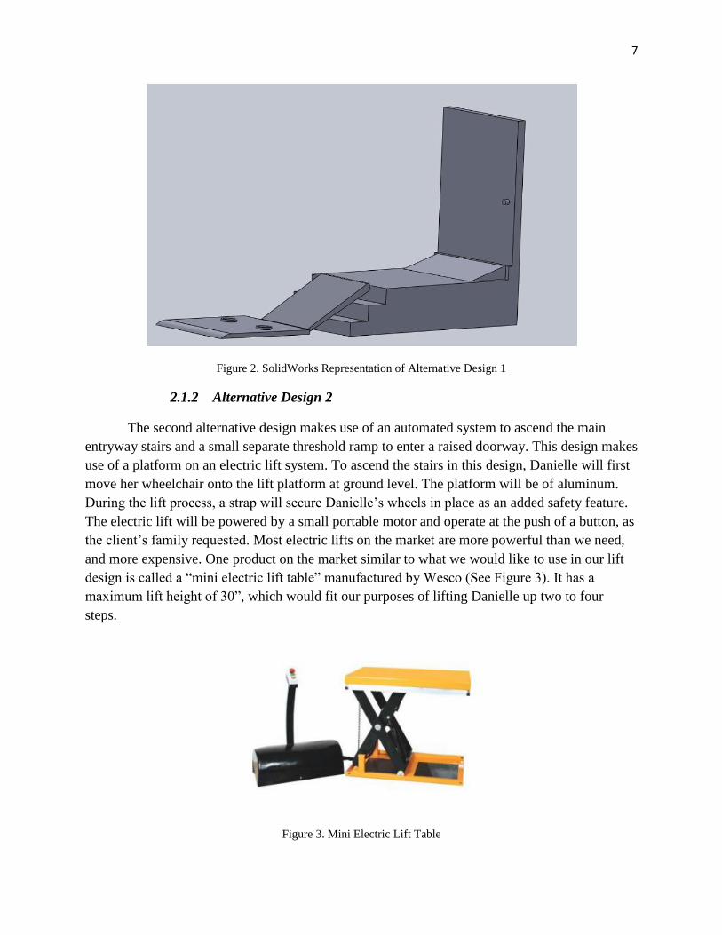
2.1.2 Alternative Design 2
The second alternative design makes use of an automated system to ascend the main
entryway stairs and a small separate threshold ramp to enter a raised doorway. This design makes
use of a platform on an electric lift system. To ascend the stairs in this design, Danielle will first
move her wheelchair onto the lift platform at ground level. The platform will be of aluminum.
During the lift process, a strap will secure Danielle’s wheels in place as an added safety feature.
The electric lift will be powered by a small portable motor and operate at the push of a button, as
the client’s family requested. Most electric lifts on the market are more powerful than we need,
and more expensive. One product on the market similar to what we would like to use in our lift
design is called a “mini electric lift table” manufactured by Wesco (See Figure 3). It has a
maximum lift height of 30”, which would fit our purposes of lifting Danielle up two to four
steps.
Figure 3. Mini Electric Lift Table
8
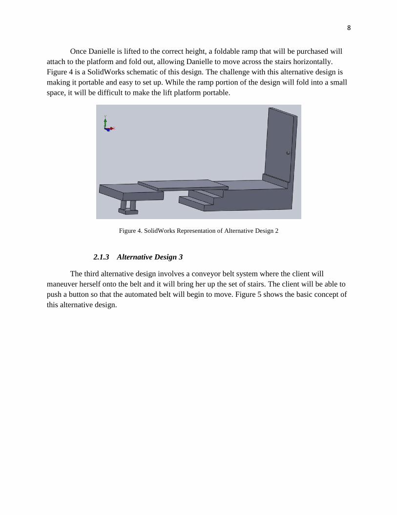
Once Danielle is lifted to the correct height, a foldable ramp that will be purchased will
attach to the platform and fold out, allowing Danielle to move across the stairs horizontally.
Figure 4 is a SolidWorks schematic of this design. The challenge with this alternative design is
making it portable and easy to set up. While the ramp portion of the design will fold into a small
space, it will be difficult to make the lift platform portable.
Figure 4. SolidWorks Representation of Alternative Design 2
2.1.3 Alternative Design 3
The third alternative design involves a conveyor belt system where the client will
maneuver herself onto the belt and it will bring her up the set of stairs. The client will be able to
push a button so that the automated belt will begin to move. Figure 5 shows the basic concept of
this alternative design.

9
Figure 5. SolidWorks Representation of Alternative Design 3
This system will not be portable due to the complexity involved with setting it up.
Danielle will be able to move onto the conveyor belt system and begin to move up the stairs at
the push of a button. There will be a small ramp at the beginning of the belt, as well as at the end,
so that the client can easily get on or off. The belt will not span all the way to the threshold of the
door. Since there is a 6” threshold, a small portable ramp will be implemented so that the client
can easily get into the doorway of the house. The system will feature a control box where the
client’s parents will be able to control the movement of the system. This gear box will be
attached to the belt and will have switches for forward and reverse movement so that the client
can go either enter or exit the house. The rollers are powered by a mechanical drive system that
moves the rubber belt on top. The rollers rotate and are able to move the belt in each direction.
This is similar to the design of the automatic sidewalks that are seen in many airports across the
country that allow transport of passengers from one side of the airport to another. One of the
major disadvantages of this alternative design is that it does not allow portability of the system.
The client had requested that a lifting mechanism be designed to be universal in order to allow
the client to go up a set of many different staircases. This system is bulky and does not collapse
very well. The benefit of a ramp or conveyor belt system is that it can be used with any
reasonable height staircase spanning 3 or 4 steps because it simply spans from the bottom of the
steps to the stop of the steps. Therefore, it does not matter how many steps there are in front of
the house, or the respective height of each step itself.
10
2.2 Optimal Design
2.2.1 Objective
The automatic lift to ascend and descend front steps will be functional and practical for the
Giroux family. There are several critical components to the automatic lift that will be taken into
careful consideration. The client requests that the lift be transportable so that it can be used in
several locations. The lift will also be collapsible and able to fit into the family van. When
collapsed, the lift will not exceed a width of 8” to ensure enough room for the client and her
family members inside the van without jeopardizing safety. It is necessary that the lift also have
tie downs at the base for the client’s wheelchair. The tie-downs will secure the client and her
wheelchair to the lift surface so that there is no possibility of the client slipping or sliding off the
lift. Moreover, the client’s parents requested that the lift only be functional with parental
supervision. The lift will not be accessible to the client herself, and will only be able to start and
stop with assistance from a second party. The lift will be built to suit the client’s manual
wheelchair, as opposed to the client’s electric wheelchair. The manual wheelchair is lightweight
and portable, weighing approximately 30 pounds. The client weighs approximately 75 pounds so
the ramp will be designed to withstand approximately 105 pounds. The ramp will also be
designed to hold more weight to ensure that as the client grows she can continue to use the lift.
The lift will consist of a pair of motorized scissor jacks that will lift a 20”x32”1/4” aluminum
platform, with a ramp attached to it. The scissor lift will be automatic and portable. The lift
capacity is 600 lbs which is suitable for the client. The lift can reach heights from 10” to 30”
which is ideal for a variety of stairs. The lift is automatically operated using a remote control that
will simultaneously move both scissor jacks. Each scissor jack will have its own motor, and the
pair will be attached to one battery. Furthermore, the remote control will be attached to the
singular battery, and it will automate both jacks at once to ensure steady vertical rise and descent.
The jacks will be house in an aluminum base. Aluminum will be used instead of steel because it
is lighter weight for easy transport. Two swivel caster wheels will be attached to the side of the
base. This will enable to the client to tip the lift system (when it is not in use) on its side for
transportability. When the lift is not in use, the platform will rest on the base containing the two
scissor jacks, and will appear to be an aluminum box. The platform of the scissor lift will be
20”x32” and ¼” thick. The platform will be equipped with tie downs for the client’s wheelchair
for safety. To raise the lift, the client’s parents will use the remote control to lift the platform to
the desired height. Contrarily wise, to lower the lift, the client’s parents will use the remote
control to lower the scissor jacks. Furthermore, the scissor lift will require good quality oil with
150 SSU at 100°F. The oil must also have rust and oxidation inhibitors and anti-wear properties.
Oils to use are Exxon/Mobil DTE 24, Exxon/Mobil NUTO H32, or Chevron Amaco AW32. It is
very important to keep the hydraulic oil free of dirt, rust, metal chips, water, and other
contamination. This is because most problems with hydraulic systems are caused by
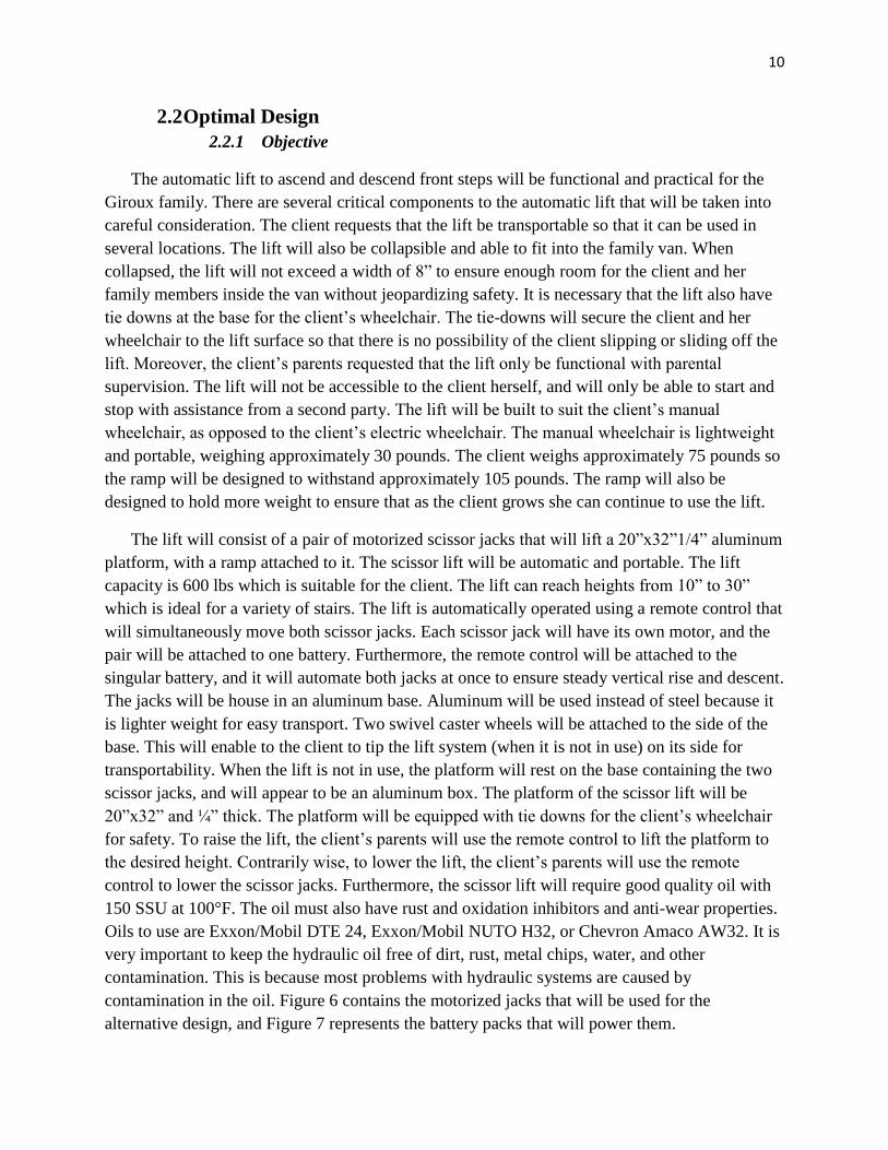
contamination in the oil. Figure 6 contains the motorized jacks that will be used for the
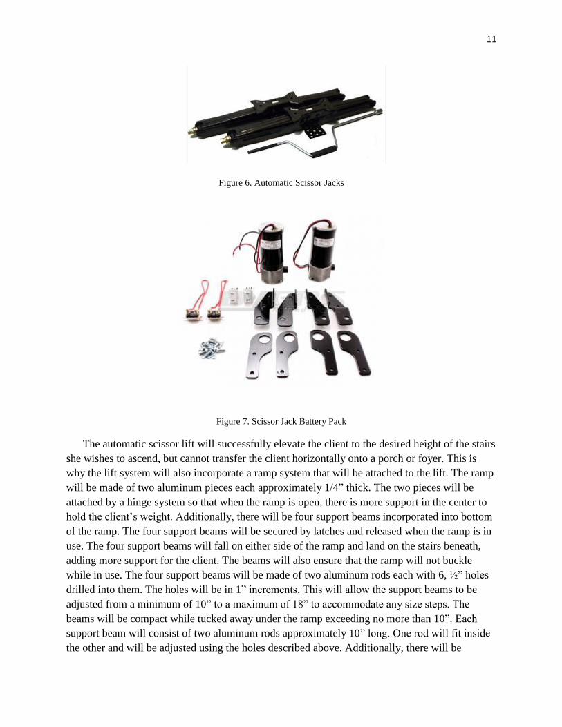
alternative design, and Figure 7 represents the battery packs that will power them.
11
Figure 6. Automatic Scissor Jacks
Figure 7. Scissor Jack Battery Pack
The automatic scissor lift will successfully elevate the client to the desired height of the stairs
she wishes to ascend, but cannot transfer the client horizontally onto a porch or foyer. This is
why the lift system will also incorporate a ramp system that will be attached to the lift. The ramp
will be made of two aluminum pieces each approximately 1/4” thick. The two pieces will be
attached by a hinge system so that when the ramp is open, there is more support in the center to
hold the client’s weight. Additionally, there will be four support beams incorporated into bottom
of the ramp. The four support beams will be secured by latches and released when the ramp is in
use. The four support beams will fall on either side of the ramp and land on the stairs beneath,
adding more support for the client. The beams will also ensure that the ramp will not buckle
while in use. The four support beams will be made of two aluminum rods each with 6, ½” holes
drilled into them. The holes will be in 1” increments. This will allow the support beams to be
adjusted from a minimum of 10” to a maximum of 18” to accommodate any size steps. The
beams will be compact while tucked away under the ramp exceeding no more than 10”. Each
support beam will consist of two aluminum rods approximately 10” long. One rod will fit inside
the other and will be adjusted using the holes described above. Additionally, there will be
12
railings attached to the ramp system to ensure the client’s safety while maneuvering across the
ramp.
The final component to the lift system will be a threshold ramp located at the threshold of the
desired location. Since the ramp is not automated, once the client has been elevated by the
scissor ramp and maneuvered onto the porch over the ramp described above, she will need to
finally go over the threshold ramp to enter the building. The threshold ramp will also be made of
aluminum and will be adjustable. The maximum height for the threshold ramp will be 6”. Once
the client is safely in the desired location, the ramp can be folded up and the lift can be lowered.
The threshold ramp can be taken away manually and will not weigh more than 20 lbs. The
lift/ramp system will be able to be rolled and stored away until the client is ready to exit the
building.
2.2.2 Subunits
2.2.2.1 Motorized Jacks and Battery
The automatic lift system for Danielle will incorporated two motorized jacks that will
simultaneously elevate a platform. The motorized jacks will work at the same time to rotate the
inner hinge to raise or collapse the jacks by remote control. The jacks have a maximum elevation
of 30” which is ideal for an assistive device to reach two to four stairs. Figure 7 above is a
picture of the two motorized jacks that will be used. Each motorized jack comes separately and is
controlled by one remote control. To enhance the optimal design and make it easier for the client
to use, the two motorized jacks will be wired together and controlled by just one remote instead
of two. This will make activation much easier for the client, as well as ensure that the jacks are
traveling the same distance at the same speed.
Additionally, the motorized jacks will be connected to one battery, shown in figure 8
above. The BAL Product Scissor Jack Power Pack will be purchased and used to operate the
motorized jacks. The jacks and battery will remain inside the base structure of the device. When
the jacks are not in use (downward position), they will be hidden by the base structure and the
platform. The device will appear as just an aluminum box with wheels on the side, so it is very
discrete and relatively easy to transport. An advantage of using the motorized jacks and battery
pack described above is that they are both relatively lightweight. The weight of both jacks plus
the battery does not exceed 40 lbs. The platform, the client, and her wheelchair, weigh a
combined 150 lbs, so the jacks are more than powerful enough to elevate the client to the desired
height without any strain on the system.
2.2.2.2 Platform
The platform for the automatic lift system will be made of aluminum and manufactured
in the University of Connecticut Senior Design Lab and workshop. The platform will be a
20”x32” sheet of aluminum approximately 1/4” thick. The weight of the platform is
approximately 15.5 lbs, and will be able to hold the weight of the client and her wheelchair.
13
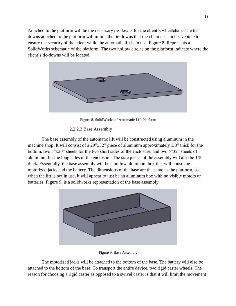
Attached to the platform will be the necessary tie-downs for the client’s wheelchair. The tie
downs attached to the platform will mimic the tie-downs that the client uses in her vehicle to
ensure the security of the client while the automatic lift is in use. Figure 8. Represents a
SolidWorks schematic of the platform. The two hollow circles on the platform indicate where the
client’s tie-downs will be located.
Figure 8. SolidWorks of Automatic Lift Platform
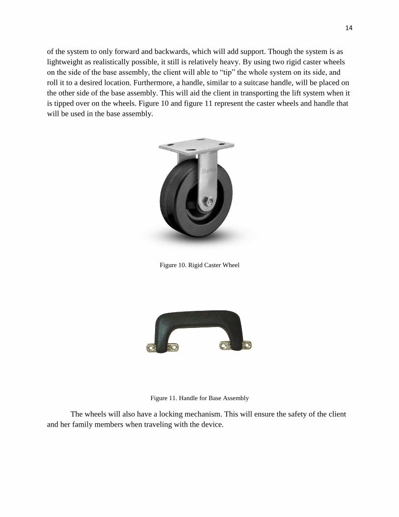
2.2.2.3 Base Assembly
The base assembly of the automatic lift will be constructed using aluminum in the
machine shop. It will consist of a 20”x32” piece of aluminum approximately 1/8” thick for the
bottom, two 5”x20” sheets for the two short sides of the enclosure, and two 5”32” sheets of
aluminum for the long sides of the enclosure. The side pieces of the assembly will also be 1/8”
thick. Essentially, the base assembly will be a hollow aluminum box that will house the
motorized jacks and the battery. The dimensions of the base are the same as the platform, so
when the lift is not in use, it will appear to just be an aluminum box with no visible motors or
batteries. Figure 9. is a solidworks representation of the base assembly.
Figure 9. Base Assembly
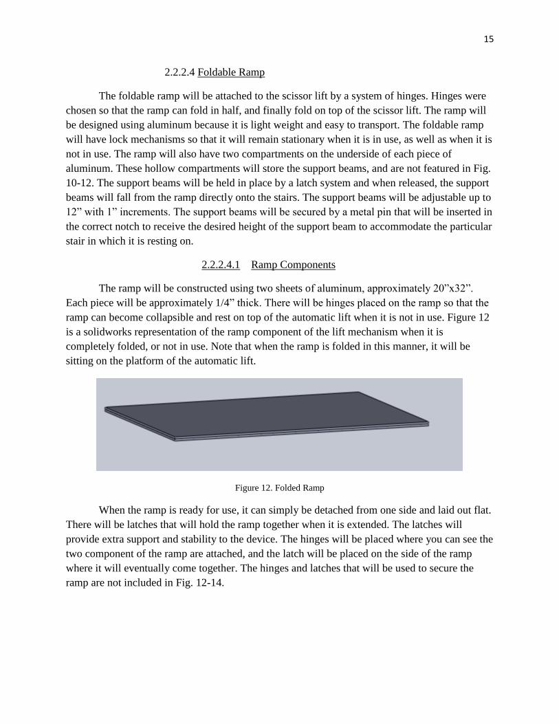
The motorized jacks will be attached to the bottom of the base. The battery will also be
attached to the bottom of the base. To transport the entire device, two rigid caster wheels. The
reason for choosing a rigid caster as opposed to a swivel caster is that it will limit the movement
14
of the system to only forward and backwards, which will add support. Though the system is as
lightweight as realistically possible, it still is relatively heavy. By using two rigid caster wheels
on the side of the base assembly, the client will able to “tip” the whole system on its side, and
roll it to a desired location. Furthermore, a handle, similar to a suitcase handle, will be placed on
the other side of the base assembly. This will aid the client in transporting the lift system when it
is tipped over on the wheels. Figure 10 and figure 11 represent the caster wheels and handle that
will be used in the base assembly.
Figure 10. Rigid Caster Wheel
Figure 11. Handle for Base Assembly
The wheels will also have a locking mechanism. This will ensure the safety of the client
and her family members when traveling with the device.
15
2.2.2.4 Foldable Ramp
The foldable ramp will be attached to the scissor lift by a system of hinges. Hinges were
chosen so that the ramp can fold in half, and finally fold on top of the scissor lift. The ramp will
be designed using aluminum because it is light weight and easy to transport. The foldable ramp
will have lock mechanisms so that it will remain stationary when it is in use, as well as when it is
not in use. The ramp will also have two compartments on the underside of each piece of
aluminum. These hollow compartments will store the support beams, and are not featured in Fig.
10-12. The support beams will be held in place by a latch system and when released, the support
beams will fall from the ramp directly onto the stairs. The support beams will be adjustable up to
12” with 1” increments. The support beams will be secured by a metal pin that will be inserted in
the correct notch to receive the desired height of the support beam to accommodate the particular
stair in which it is resting on.
2.2.2.4.1 Ramp Components
The ramp will be constructed using two sheets of aluminum, approximately 20”x32”.
Each piece will be approximately 1/4” thick. There will be hinges placed on the ramp so that the
ramp can become collapsible and rest on top of the automatic lift when it is not in use. Figure 12
is a solidworks representation of the ramp component of the lift mechanism when it is
completely folded, or not in use. Note that when the ramp is folded in this manner, it will be
sitting on the platform of the automatic lift.
Figure 12. Folded Ramp
When the ramp is ready for use, it can simply be detached from one side and laid out flat.
There will be latches that will hold the ramp together when it is extended. The latches will
provide extra support and stability to the device. The hinges will be placed where you can see the
two component of the ramp are attached, and the latch will be placed on the side of the ramp
where it will eventually come together. The hinges and latches that will be used to secure the
ramp are not included in Fig. 12-14.
16
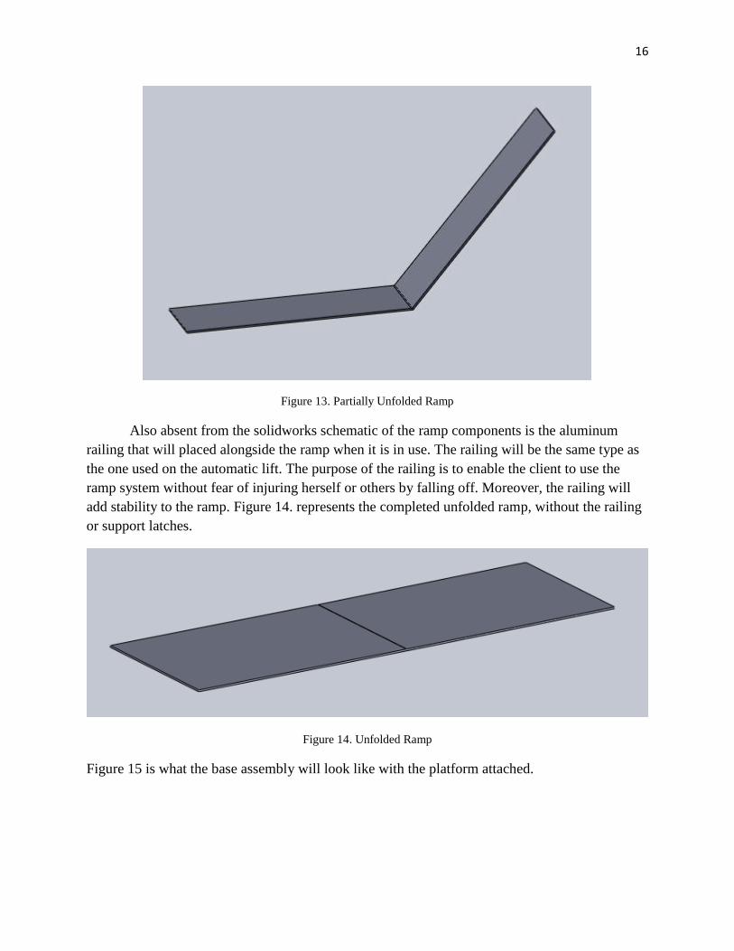
Figure 13. Partially Unfolded Ramp
Also absent from the solidworks schematic of the ramp components is the aluminum
railing that will placed alongside the ramp when it is in use. The railing will be the same type as
the one used on the automatic lift. The purpose of the railing is to enable the client to use the
ramp system without fear of injuring herself or others by falling off. Moreover, the railing will
add stability to the ramp. Figure 14. represents the completed unfolded ramp, without the railing
or support latches.
Figure 14. Unfolded Ramp
Figure 15 is what the base assembly will look like with the platform attached.

17
Figure 15. Base Assembly with Platform
2.2.2.4.2 Latch/Hinge to Secure Components
The ramp will be created using two identical pieces of aluminum. The two pieces will be
held together using hinges such as the ones seen in Fig. 17. This will enable the ramp to fold
onto itself and be positioned on the automatic lift for easy maneuverability. Additionally, the
ramp will be secured on the side by a latch similar to that in Fig. 16. This latch system will
ensure that the ramp will not buckle underneath the client’s weight.
Figure 16. Latch Figure 17. Hinge
2.2.2.4.3 Support Rods
The support rods will be tucked away in a hollow grove underneath the two ramp
components. The rods will be made of two hollow aluminum pieces. The outer component will
be approximately 2”x4” and approximately 1/16” thick. The inner rod will fit snuggly inside the
outer rod and will be 1.5”x3.5” and also 1/16” thick. Figure 18. represents a solidworks
schematic of the support rod outer component.

18
Figure 18. Support Rod Component
Each component of the rod (outer and inner) will be 10” long. The holes that will make
the rods adjustable are located 1” from the top and bottom of the rod and are 1” apart. The holes
are ½” in diameter. When the rod is fully extended it will reach a maximum height of 18”. This
is ideal for a bottom step. When the rod is fully collapsed, it will have a minimum height of 10”.
This is ideal for a second step. Figure 19. is a solidworks schematic of the rod when slightly
adjusted.

19
Figure 19. Assembled Support Rod
The outer and inner component of the support beam will be held together by an
aluminum pin that is approximately 2.5” long with a ½” diameter. The pin will fit snuggly into
the appropriate notch on the support beam to ensure no slippage when the ramp is in use. Figure
20. is a solidworks schematic of the support pin insert that will be used for the support beams.
20
Figure 20. Support Insert
There will be a total of four support beams located on either side of each ramp
component. Each support beam will consist of an outer and inner piece as well as a support pin.
All components will be made of aluminum. The rods will be stored underneath the ramp and
attached by latches.
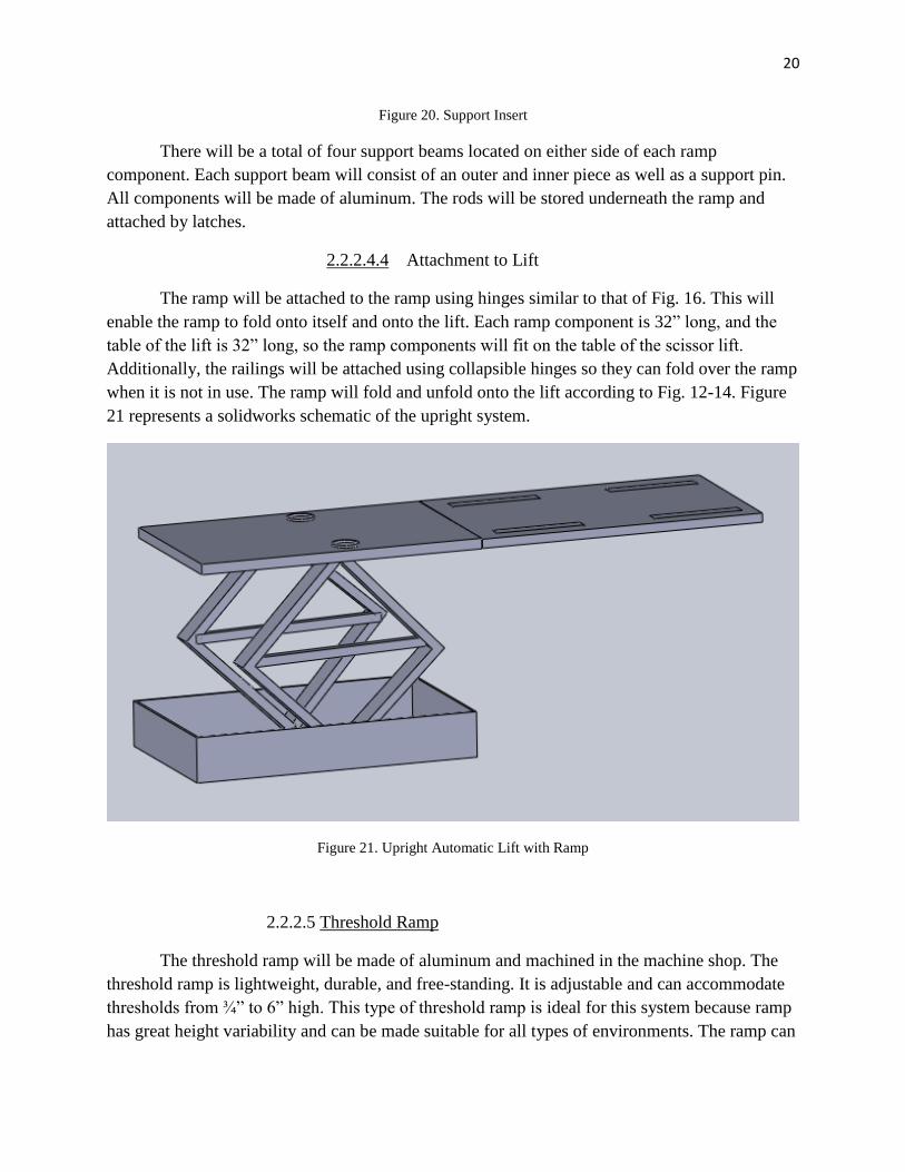
2.2.2.4.4 Attachment to Lift
The ramp will be attached to the ramp using hinges similar to that of Fig. 16. This will
enable the ramp to fold onto itself and onto the lift. Each ramp component is 32” long, and the
table of the lift is 32” long, so the ramp components will fit on the table of the scissor lift.
Additionally, the railings will be attached using collapsible hinges so they can fold over the ramp
when it is not in use. The ramp will fold and unfold onto the lift according to Fig. 12-14. Figure
21 represents a solidworks schematic of the upright system.
Figure 21. Upright Automatic Lift with Ramp
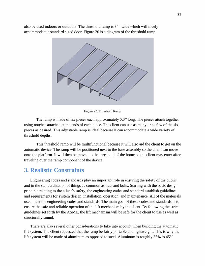
2.2.2.5 Threshold Ramp
The threshold ramp will be made of aluminum and machined in the machine shop. The
threshold ramp is lightweight, durable, and free-standing. It is adjustable and can accommodate
thresholds from ¾” to 6” high. This type of threshold ramp is ideal for this system because ramp
has great height variability and can be made suitable for all types of environments. The ramp can
21
also be used indoors or outdoors. The threshold ramp is 34” wide which will nicely
accommodate a standard sized door. Figure 20 is a diagram of the threshold ramp.
Figure 22. Threshold Ramp
The ramp is made of six pieces each approximately 5.3” long. The pieces attach together
using notches attached at the ends of each piece. The client can use as many or as few of the six
pieces as desired. This adjustable ramp is ideal because it can accommodate a wide variety of
threshold depths.
This threshold ramp will be multifunctional because it will also aid the client to get on the
automatic device. The ramp will be positioned next to the base assembly so the client can move
onto the platform. It will then be moved to the threshold of the home so the client may enter after
traveling over the ramp component of the device.
3. Realistic Constraints
Engineering codes and standards play an important role in ensuring the safety of the public
and in the standardization of things as common as nuts and bolts. Starting with the basic design
principle relating to the client’s safety, the engineering codes and standard establish guidelines
and requirements for system design, installation, operation, and maintenance. All of the materials
used meet the engineering codes and standards. The main goal of these codes and standards is to
ensure the safe and reliable operation of the lift mechanism by the client. By following the strict
guidelines set forth by the ASME, the lift mechanism will be safe for the client to use as well as
structurally sound.
There are also several other considerations to take into account when building the automatic
lift system. The client requested that the ramp be fairly portable and lightweight. This is why the
lift system will be made of aluminum as opposed to steel. Aluminum is roughly 35% to 45%

22
lighter than steel while still maintaining structural integrity. Furthermore, there are several
dimensions to the ramp that are adjustable. The automatic lift has a minimum height of 7” and a
maximum height of 30”. This will allow the lift to accommodate a variety of stair heights.
Furthermore, the ramp that will be attached to the lift will also have a varying length to
accommodate different foyer distances. The four support beams located under the ramp are also
adjustable. The support beams will be able to adapt to heights as low as 10” all the way up to
18”. This will ensure that the ramp will have the necessary support no matter the dimensions of
the stoop. Since the client will mainly be using the lift mechanism in other locations besides her
own home, these adjustable components to the lift system are crucial. There is no need to make a
stationary ramp for the client’s home, because her home is already handicap accessible. The
client has expressed interest in using the lift system primarily at relatives’ homes. By
incorporating the adjustable support beams and the adjustable height of the scissor lift, the ramp
will be able to accommodate any stoop with two to four steps assuming that the stoop consists of
steps with average dimensions.
The use of aluminum for the lift is also beneficial for the outdoor environment in which the
lift will be used. Aluminum corrodes but it does not rust. Rust refers only to iron and steel
corrosion. Aluminum is very prone to corrosion. However, aluminum corrosion is aluminum
oxide, a very hard material that actually protects the aluminum from further corrosion. The ramp
will not be stored outside, but it will be used outside, so a material that resists rust and corrosion
will extended the lifetime of the lift system. When the lift system is not in use it should be stored
indoors. The ramp will not need to be stored in room temperature, however, so it can be stored in
the garage when not in use.
The lift system will incorporate several structures to ensure the ramp is safe for the client to
use. Mainly the four support beams that will be located under the ramp attached to the lift. When
these support beams fall onto the stair, they will be able to be adjusted to various different
heights to accommodate any type of stoop. Furthermore, the ramp itself will be designed to give
itself added support in the middle. The ramp will be made with two pieces of aluminum that join
together in the middle and held in place by a latch system. The latch will ensure that the ramp
will not buckle under the weight of the client. The lift and ramp will be designed to hold a
combined 300 lbs. Currently the client and her wheelchair weigh approximately 110 lbs. The
extra weight the lift system can withstand will benefit the client because she can use this device
in the following years, because she is still growing. Moreover, the platform will incorporate tie
downs for the client’s wheelchair. The client will maneuver herself onto the platform when the
lift is not elevated. The client’s caregiver will then tie down the wheelchair to lock it in place
while the lift is in motion. Once the client has been elevated to the desired height, the ramp will
be released and the client’s wheelchair will be released from the ties and free to move across the
ramp. Furthermore, there will be railings incorporated on the ramp to ensure the client will not
accidently fall off the ramp or the lift.
23
The lift system will be based off existing scissor lifts, but with new technology and
adaptations added on to it. Most scissor lifts are made of stainless steel. This device will be made
of aluminum because it is lighter weight and still structurally sound. Moreover, this ramp is for
the personal use of one client. This lift system will be built to accommodate the client’s requests.
Manufacturing a ramp system like this would benefit many people with limited mobility.
However, this particularly design will not be manufactured because it is being custom built for
one client.
The lift system will greatly improve the client’s quality of life. Currently the client has no
safe way to enter or exit a building that is not handicap accessible. This lift mechanism will give
the client a safe and reliable way to not only gain entry into her own home, but in the homes’ of
relatives or other locations that are not handicap accessible. The portability of the ramp is also a
great benefit for the client. To be able to bring this device to several locations will enrich the
client’s social experiences.
4. Safety Issues
Safety of the client is the number one priority for this design. The lift and ramp mechanisms
will need to be structurally sound and tested before the client will be able to use the device. Most
scissor lifts are made with stainless steel; the optimal design for this device calls for the scissor
lift to be made of aluminum. Mechanical testing and analysis will need to be completed to ensure
that an aluminum lift will maintain the structural and mechanical integrity of the lift the same
way stainless steel does.
There are several more mechanical safety issues involving the optimal design. Since the
design has a ramp incorporated into the scissor lift, several precautions will be taken to ensure
the ramp will not buckle underneath the client’s weight. The client and her wheelchair weigh
approximately 110 pounds. The automatic lift and ramp will hold approximately 600 pounds.
The four support beams located underneath the ramp will add support to the ramp. The support
beams will lie on the steps and hold the ramp up when it is in use. Additionally, the ramp will be
made of two aluminum pieces secured by a hinge/latch system. When the ramp is in use, the
latch will be secured across the two pieces of aluminum that comprise the ramp. This feature also
adds mechanical support to the lift system. Furthermore, there will be a railing attached to the lift
and the ramp when it is in use. This will provide the client with additional security when using
the lift system. The railing will ensure that the client will remain on the ramp at all times while in
use, even if the client were to lose control of her wheelchair. The scissor lift will also have a foot
operated floor lock to position the lift in place. To raise the lift, turn the release knob clockwise
until it is fully closed. Press on the foot pedal to raise the scissor lift. To lower the lift, slowly
turn release knob counter-clockwise until the desired rate of decent is achieved. To lock lift in
position, press down on the wheel breaks located on the swivel casters at the push handle end.
This will be controlled by the client’s caregiver. This safety precaution is necessary so that the

24
client cannot operate the lift alone. This ensures the client’s safety and the sustainability of the
lift system.
Routine inspection maintenance should be performed on the lift on a monthly basis to ensure
that there are no hazards to the client. The wheels should be lubricated, as well as all pivot points
with medium weight oil or light grease. The oil level will also have to be periodically checked
and filled if needed. The recommended hydraulic oil for the optimal design is a Citgo AW32. It
is very important to keep the hydraulic oil free of dirt, rust, metal chips, water, and other
contamination. This is because most problems with hydraulic systems are caused by
contamination in the oil.
5. Impact of Engineering Solutions
Engineering solutions have a major impact on society. Some impacts are positive, such as
water treatment systems, and some are negative, such as nuclear weapons. It is critical that
engineers give proper attention to the safety and cost of their products because they are two
aspects that impact all users of engineering products, and therefore society as a whole. This
optimal design incorporates several issues surrounding the impact of engineering solutions. The
lift system implemented in the optimal design is hydraulic. Therefore, there is no pollution or
greenhouse gas emission when the lift is in use. This feature of the ramp protects the
environment on a local and global spectrum. Additionally, the ramp will be relatively
inexpensive to design and create. The ramp will not be mass manufactured since it is being
custom built for one client.
The impact of this device can be observed most in the societal engineering solutions. The
main concern of the client is that she is unable to enter and exit buildings that are not handicap
accessible. Though this does not apply to public buildings, it affects any resident location. The
lift system will enable to client to visit friends and family’s homes without embarrassment or
trouble getting in and out of the home that is not handicap accessible. Essentially, the ramp
system will give the client a social benefit more than anything else.
The lift system will also be very easy to operate. You do not need to be an engineer to use
and maintain this device. The client’s primary caregivers are her parents and family members.
They will not need any special training to use this device, nor will they need to make any major
maintenance decisions. The lift system is not electronic, so there is no troubleshooting that needs
to be incorporated. Once the lift is assembled and tested, the client will be able to easily use it
without the help of any of the team members. This will give the client the freedom she desires as
well as the security her parents desire.
The social, economic, and environmental realities that surround globalization present
engineers with the challenge to understand the social context of the design process and the global
impact the design will create. The optimal design for the lift system will be beneficial in all

25
categories and have only positive effects in the global, environmental, economic, and societal
context.
6. Life-Long Learning
There are several new techniques learned while designing the optimal design for the lift
system. The scissor lift will be manufactured in the Senior Design Machine Shop by the team
members and it will not be purchased. Therefore the proper machine shop techniques acquired
include use of the saw mill and the lathe to create the parts needed to complete the optimal
design. Additionally, to analyze the components before they are put together, SolidWorks will be
implemented. The program used is brand new and the analysis will show that the dimensions of
the scissor lift and the ramp will be able to support the client while the ramp is in use.
The lift system will incorporate several techniques that have never been implemented before.
None of the team members have any experience building anything like the lift system. This
includes the assembly of the hydraulic pump for the scissor lift, the ramp system that will be
attached to the lift, as well as the maneuverability of the lift system as a whole. This brings a
degree of mechanical engineering expertise to the table that has never been implemented before.
The design project also incorporated the values of working as a team. This design project
cannot be accomplished by one person: it takes a collaborative approach to fix any problems and
assess any flaws in the design. The design will be very time consuming to accomplish because it
is mostly being machined by hand. This entails a lot of mechanical experience as well as
patience. The team members will all work together to accomplish this design.
This design has incorporated a lot of manufacturing techniques. Each step in the design
process requires careful planning and research. Since the beginning of the design process, the lift
system has gone through several changes. The optimal design outlined in this report is different
from each of the alternative designs. There are several factors that contribute to the final design,
such as materials, environmental properties, workspaces, as well as competency.
7. Budget and Timeline 7.1 Budget
The budget estimation for this design is approximately $388. The aluminum that will be
used for the design was donated to us and will not cost any money. Table 1. details what the
remaining items will cost.
Budget for Automatic Lift System
30” Jacks $40+Shipping
Battery Power Packs $300+Shipping

26
Hinges/Latches $20
Rigid Caster Wheels $25
Handle $3
Total Budget $388 +s&h Table 1. Budget
7.2 Timeline

27
Figure 23a. Part 1 of 2 of Projected Timeline

28
Figure 23b. Part 2 of 2 of Projected Timeline

29
8. Team Member Contributions 8.1 Leah McElhaney
The majority of this project was spearheaded by Leah. Unfortunately team 5 was forced
to split up the projects due to time constraints, and to give each project assigned the proper
attention. All three team members are actively involved in all three projects, but the written
reports and design ideas for the automatic lift system were all headed by Leah.
During the design process, Leah visited the Giroux home two times. The purpose of these
visits was to get accurate measurements for the automatic lift, as well as meet the client’s and
understand their wishes in the best way possible. Another important job of Leah’s was to come
up with the initial design of the project. The project has changed several times since the
beginning of the semester, and Leah was in charge of updating the reports and making sure the
client was kept up to date on the progress of the report.
Leah, as well as the other team members, will machine the parts necessary according to
the time line in figure 23a and 23b. This will require extensive time in the machine shop, which
is why Leah, as well as Jordan, completed the Machine Shop Safety Class.
Leah also went to the NEAT marketplace with the rest of the team members to pick up
parts for the design. The parts bought at the NEAT marketplace were the support rods used for
the ramp component of the design.
8.2 Jordan Smith
Jordan’s main priority for this design project was ordering all the necessary parts and
doing adequate research on the different kinds of jacks and motors that could be used. Jordan
was in close contact with Marek and Jen in the BME office to ensure that our orders were placed
correctly.
Jordan also maintained the website for our team to keep the client up to date with our
progress. The website is an important component of this design project because it is updated
weekly, and is the best way to keep our client informed and observe the progress we’ve made on
a weekly basis. Jordan also traveled to the Giroux home three times to meet with the clients, as
well as travel to the NEAT marketplace to pick up the necessary parts.
8.3 Kayla Gosse
Kayla kept track of the budget for this design project. She kept an up-to-date record of all
expenses for all three projects to make sure that we do not go over budget on any one project.
Kayla also traveled to the client’s home to get measurements and interact with the client and her
family. Visiting with the client is very important to gain a perspective of what the client is
30
looking for out of the device. Visiting with the Giroux family is one way Kayla contributed to
this project.
9. Conclusion
The purpose of this project is to develop an automatic ramp to assist Danielle Giroux in and
out of her home, as well as in and out of other locations. Danielle Giroux is an 11 year-old girl
with cerebral palsy. She is confined to a wheel chair and therefore cannot enter or exit buildings
with stairs. Danielle’s home has a front porch with three stairs attached. The automatic ramp will
assist Danielle with getting her wheelchair in and out of her home with minimal assistance from
her family members. Additionally, this automatic ramp will be collapsible and transportable so
that Danielle and her family can bring the ramp to other locations for use, most importantly other
relatives’ homes that are not suited for people with disabilities. Currently Danielle enters and
exits her home only with the help of family members; one family member will pick Danielle out
of her wheel chair and carry her in or out of the home, while a second family member must carry
Danielle’s wheelchair in or out as well. This puts a tremendous strain on the family because
Danielle is getting older and heavier. The wheel chair she currently uses also is getting bigger as
Danielle’s needs change. The project design of the automatic ramp will eliminate the need for
Danielle’s family to physically bring her in and out of her home.
The finished device will be a combination of a system of two motorized jacks attached to a
platform, as well as a foldable ramp that will extend onto the front steps of a home, as well as a
separate threshold ramp. The device will be placed at the bottom of the stairs the client wishes to
ascend. The motorized jacks will be controlled by one remote control. By pressing the remote
control, the client will elevate to the desired height of the stairs. Then the ramp component will
be unfolded and the support rods will be put in place and secure. After the ramp component is
secure in place, the client will be released from the tie-downs on the platform and will be free to
move across the ramp onto the foyer. Once on the foyer, the client will use the threshold ramp to
gain entrance into the house.
This device works in the opposite direction as well. The client will exit the location using the
threshold ramp and move across the ramp component onto the platform. The client will then be
secured in the tie-down with help from a family member. The remote control will then lower the
motorized jacks until the client is safely on the ground, at which point the client can be released
from the tie-downs and exit the platform.
This product is unique because there is not any product like it on the market. Most ramps
available on the market are stationary and require a second party to help elevate the handicapped
individual. The ramp designed for the client will promote independence for client, as well as
make her daily life more manageable for herself as well as her family.
31
10. References
[1]: http://www.makemeheal.com/mmh/product.do?id=102831&utm_source=google&utm_
medium=product&utm_campaign=googleproduct&gclid=CLba6vP1p6sCFYSK4AodSHrgzA
[2] http://www.quickie-wheelchairs.com/wheelchair-parts/sunrise-medical/quickie-
iris/accessories/one-arm-drive-s-n-preifx-cgt
[3] http://www.wpi.edu/Pubs/E-project/Available/E-project-043009-
105716/unrestricted/Wheelchair_MQP_0809.pdf
[4] http://www.adirides.com/variable.html
[5] http://www.1800wheelchair.com/asp/view-product.asp?product_id=1470
[6] http://www.portable-wheelchair-
ramps.com/Wheelchair_ramps/aluminum_threshold_ramps.aspx
[7] http://www.abledata.com/abledata.cfm?pageid=19327&top=10815&ksectionid=0&productid
=190668&trail=22,10445,10811&discontinued=0
[8] http://www.abledata.com/abledata.cfm?pageid=19327&top=10815&ksectionid=0&productid
=190646&trail=22,10445,10811&discontinued=0
[9] http://www.patentgenius.com/patent/5870788.html
[10] http://www.abledata.com/abledata.cfm?pageid=19327&top=10643&ksectionid=19327&
productid=201563&trail=0&discontinued=0
[11] http://files.asme.org/ASMEORG/Publications/Codes/5134.pdf
[12]http://www.omni.com/products/Tilters/media/documents/downloads/Hydraulic_SL_manual.
[13] http://images.harborfreight.com/manuals/91000-91999/91315.pdf

32
[14] http://www.amazon.com/Automotive-Restraint-Tie-Down-Pockets-
Hardware/dp/B005BQUQ6G
11. Acknowledgments
Dr. Enderle: Design advice and guidance
Marek: Design advice and guidance
Giroux Family: Provided design ideas to benefit Danielle
NEAT Marketplace- Don: Assistance in finding parts
Matt at Pediaflex: Danielle’s Physical Therapist
Pete and Serge: Provided advice and materials
12. Appendix 12.1 Updated Specifications
Physical: Material Type: Aluminum:20”x32”x1/4” Platform Assembly
20”x32”x1/8” Base Platform
(2) 5”x32”x1/8” Base Long Side
(2) 5”x20”x1/8” Base Short Sides
Rigid Caster Wheels
Plastic Suitcase Handle
(2) Motorized 30” Jacks
BAL Battery Power Pack
Hinges, Latches
Mechanical: Width: 32 inches maximum
Height: 30 inches maximum
Weight Capacity: 600 lbs
Weight: 150 lbs (client+wheelchair+platform)
Speed: N/A
Power: BAL Power Battery Pack
Electrical: Motorized Jacks
12V Battery
Remote Control
Environmental: Storage Temperature: 18-25°C
Operating Temperature: -18°C to 38° C

33
Operating Environment: Outdoors
Safety: Restraints: Wheelchair tie-downs
Railing
34
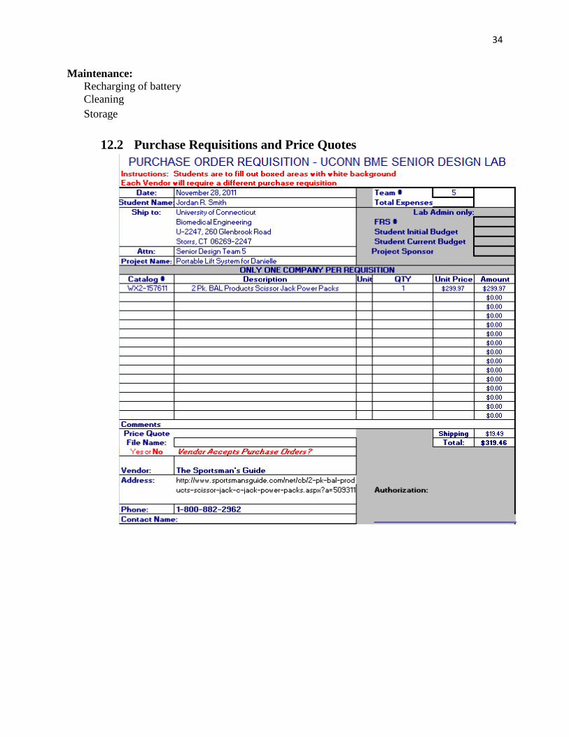
Maintenance: Recharging of battery
Cleaning
Storage
12.2 Purchase Requisitions and Price Quotes


![Mq Whiteman Senior Design Poser I Mean Poster[1]](https://img.pdfslide.tips/doc/110x75/58ee7bd31a28ab671c8b46ed/mq-whiteman-senior-design-poser-i-mean-poster1.jpg)