Embed Size (px)
Citation preview
Riveteuse Pneumatiquepneumatisch-hydraulisches NietgerätRemachador Hidráulico NeumáticoRebitadeira hidro-pneumáticaПневмозаклепочник气动拉钉机
User’s ManualAIR HYDRAULIC RIVETER
Warning Ear Protection Safety Goggles Gloves
Complete air tool solutionsw w w . m i g h t y - s e v e n . c o m
AIR HYDRAULIC RIVET NUT TOOL M3~M12PRODUCT USER MANUAL V1.01
PB-2501
www.mighty-seven.com

Contents
1 Security Introduction .......................................................................................................... 3
2 Product Information ........................................................................................................... 3
2.1 Products working abilities ........................................................................................... 3
........................................................... 3 2.2 Technical information .............................................................
3 Preparation Before Use ...................................................................................................... 4
3.1 Recommended compressed air supply ....................................................................... 4
....................................... 5 3.2 Replacement of the Stem .......................................................
.......................... 6 3.3 Stem adjustment lever/ pressure adjustment Working air pressure
4 Operating Instructions ........................................................................................................ 7
4.1 Methods of operation ................................................................................................. 7
4.2 Enforce withdraw ......................................................................................................... 8
5 Product Maintenance ......................................................................................................... 8
5.1 Routine maintenance .................................................................................................. 8
5.2 Supplementary hydraulic oil in hydraulic system ........................................................ 8
........................................................ 9
........................................................ 9
6 Maintenance and technical services .............................................
6.1 Technical assistance / product number .................................
7 Common problems and failure analysis ........................................................................... 10
8 Recycling ........................................................................................................................... 10
9 Decomposition Diagram / Parts List ................................................................................. 11
1 Security Introduction
Please read the operator's manual for the safety of the content, and observe the following
precautions:
1. This product is only suitable for single person operation and educated trained personnel
may use this product.
2. The operator must not wear loose clothing, neckties, jewelry, to avoid being caught by
the tool, causing injury.
3. If you pull the cap has been installed on the rod, and do not directly touch the pull cap
end.
4. Compressed air pressure shall not exceed 7bar.
5. To ensure the quality of life of the tool and the well work of the tool, the air must pass
trough 3 assemble points (regulator - filtration - Lubrication) processing.
6. When you are using the product, please wear safety glasses.
7. Do not operate the product in front or around people
8. Products need to be placed under a rubber mat platform and avoid the product fall
down
9. For any product repair or adjustment, remember to disassembly the tool first
10. Before any adjustments in the product, service, cleaning and maintenance , be sure to
cut off the compressed air source connection.
11. For the work area keep it clean and tidy.
12. Avoid hose near heat sources or sharp objects.
13. If you accidentally let the oil gets on your skin, wash with soap and alkaline water.
14. Do not use the products in the flammable and explosive environment and possible
burning environment
2 Product Information
2.1 Product working capabilities
Pull cap applicable specifications: M3 ~ M12.
Applicable pull cap material: aluminum pull cap, pull the cap iron, stainless steel pull cap.
3.1
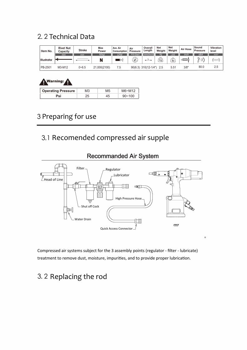
Compressed air systems subject for the 3 assembly points (regulator - filter - lubricate)
treatment to remove dust, moisture, impu es, and to provide proper lub on.
3. 2
Head of Line
Filter Regulator Lubricator
High Pressure Hose
Quick Access Connector
Shut off Cock
Water Drain
Operating Pressure M3 M5 M6~M12Psi 25 45 90~100
Recomended compressed air supple
Replacing the rod
3 Preparing for use
2. 2
mm mm (bar) mm(Inch)
MaxPowerN(kg) CFM
Ave. AirConsumption
Air Pressure
Overall Length
kg
Net Weight
Net Weight Air Hose Sound
PressureVibrationlevel
PB-2501 M3-M12 0~6.5 21,000(2100) 7.5 90(6.3) 310(12-1/4") 2.5 5.51 3/8" 80.0 2.5
CapacityRivet Nut
Stroke
Technical Data
Warning:
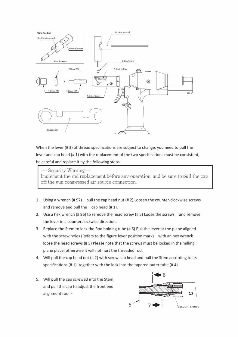
When the lever (# 3) of thread specifica ons are subject to change, you need to pull the
lever and cap head (# 1) with the replacement of the two specifica ons must be consistent,
be careful and replace it by the following steps:
1. Using a wrench (# 97) pull the cap head nut (# 2) Loosen the counter-clockwise screws
and remove and pull the cap head (# 1).
2. Use a hex wrench (# 96) to remove the head screw (# 5) Loose the screws and remove
the lever in a counterclockwise dire on.
3. Replace the Stem to lock the Rod holding tube (# 6) Pull the lever at the plane aligned
with the screw holes (Refers to the figure lever po on mark) with an hex wrench
loose the head screws (# 5) Please note that the screws must be locked in the milling
plane place, otherwise it will not hurt the threaded rod.
4. Will pull the cap head nut (# 2) with screw cap head and pull the Stem according to its
specifi ons (# 1), together with the lock into the tapered outer tube (# 4)
5. Will pull the cap screwed into the Stem,
and pull the cap to adjust the front end
alignment rod.。
Plane Posi on
Iden fica on marks
Plane Number
Rod Schema
96. Hex Wrench
1.Head M3
2.Head M4
3.Head M5
4.Outer Core
5. Hex Screw
6. Rod Holder
97.Spanner
6
Vacuum sleeve 5 7
== Security Warning==Implement the rod replacement before any operation, and be sure to pull the capoff the gun compressed air source connection.
6. Adjust Rivet Nuts head (# 1) stick to pull the cap
7. Will pull the cap head nut (# 2) locking.
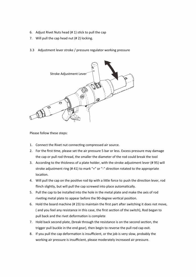
3.3 Adjustment lever stroke / pressure regulator working pressure
Please follow these steps:
1. Connect the Rivet nut connecting compressed air source.
2. For the first time, please set the air pressure 5 bar or less. Excess pressure may damage
the cap or pull rod thread, the smaller the diameter of the rod could break the tool
3. According to the thickness of a plate holder, with the stroke adjustment lever (# 95) will
stroke adjustment ring (# 41) to mark "+" or "-" direction rotated to the appropriate
location.
4. Will pull the cap on the positive rod tip with a little force to push the direction lever, rod
flinch slightly, but will pull the cap screwed into place automatically.
5. Pull the cap to be installed into the hole in the metal plate and make the axis of rod
riveting metal plate to appear before the 90-degree vertical position.
6. Hold the board machine (# 23) to maintain the first part after switching it does not move,
( and you feel any resistance in this case, the first section of the switch), Rod began to
pull back and the rivet deformation is complete
7. Hold back second plate, (break through the resistance is on the second section, the
trigger pull buckle in the end gear), then begin to reverse the pull rod cap exit.
8. If you pull the cap deformation is insufficient, or the job is very slow, probably the
working air pressure is insufficient, please moderately increased air pressure.
Stroke Adjustment Lever
9. If you Rivet Nuts riveting case does not meet the needs of the stroke adjustment ring (#
41) to mark the "+" direction of rotation increases travel distance, contrary to the stroke
adjustment ring marked "-" direction of rotation to reduce travel distance.
Notice !!
If the lever stroke is insufficient, Pull the cap that would not be able and make it
firmly fixed to in the metal plate
If the stroke is too large, You could damage the threads just pull the cap and rod.
4 Operating Instructions
4.1 Method of operation
1. First cut pull cap gun compressed air source link.
2. Replace with the rod required for the job lever.
3. Adjust the lever stroke is based on the thickness of the sheet metal parts
4. Drag the cap gun connected compressed air source.
5. Pull the cap alignment with the rod, applying a little force to the push rod, rod back
down slightly, but will pull the cap screwed into place automatically.
6. Will set into the pull-Rivet Nut hat tip inserted into the hole sheet metal parts, buckle
plate machine maintained after the first paragraph does not move until the pull cap
riveting finish.
7. Continue to pull the trigger of the second part of the buckle to finally stick and pull the
lever back till reversed .
Notice !!
When is the first time to use set up the way to use,You need to set the air pressure 5
bar or less。Excess pressure may damage the cap or pull rod thread, The smaller the
diameter of the rod could be broken.
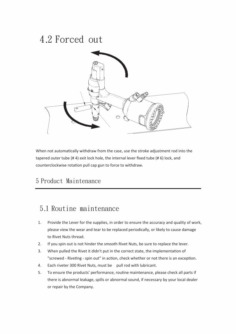
4.2 Forced out
When not automatically withdraw from the case, use the stroke adjustment rod into the
tapered outer tube (# 4) exit lock hole, the internal lever fixed tube (# 6) lock, and
counterclockwise rotation pull cap gun to force to withdraw.
5 Product Maintenance
5.1 Routine maintenance
1. Provide the Lever for the supplies, in order to ensure the accuracy and quality of work,
please view the wear and tear to be replaced periodically, or likely to cause damage
to Rivet Nuts thread.
2. If you spin out is not hinder the smooth Rivet Nuts, be sure to replace the lever.
3. When pulled the Rivet it didn't put in the correct state, the implementation of
"screwed - Riveting - spin out" in action, check whether or not there is an exception.
4. Each riveter 300 Rivet Nuts, must be pull rod with lubricant.
5. To ensure the products' performance, routine maintenance, please check all parts if
there is abnormal leakage, spills or abnormal sound, if necessary by your local dealer
or repair by the Company.
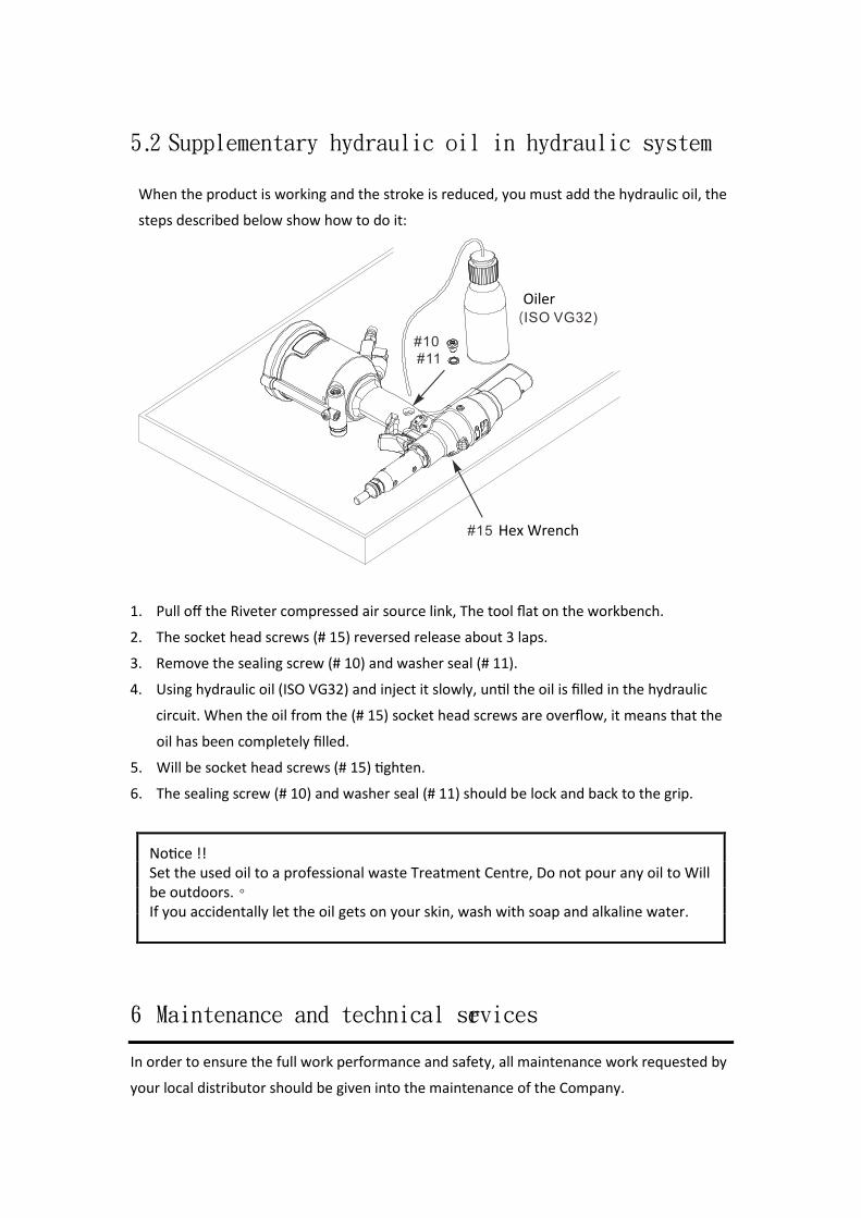
5.2 Supplementary hydraulic oil in hydraulic system
When the product is working and the stroke is reduced, you must add the hydraulic oil, the
steps described below show how to do it:
1. Pull off the Riveter compressed air source link, The tool flat on the workbench.
2. The socket head screws (# 15) reversed release about 3 laps.
3. Remove the sealing screw (# 10) and washer seal (# 11).
4. Using hydraulic oil (ISO VG32) and inject it slowly, until the oil is filled in the hydraulic
circuit. When the oil from the (# 15) socket head screws are overflow, it means that the
oil has been completely filled.
5. Will be socket head screws (# 15) tighten.
6. The sealing screw (# 10) and washer seal (# 11) should be lock and back to the grip.
6 Maintenance and technical services
In order to ensure the full work performance and safety, all maintenance work requested by
your local distributor should be given into the maintenance of the Company.
Oiler
Notice !!Set the used oil to a professional waste Treatment Centre, Do not pour any oil to Will be outdoors.。If you accidentally let the oil gets on your skin, wash with soap and alkaline water.
Hex Wrench
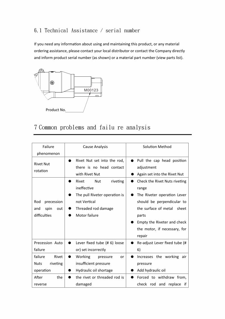
6.1 Technical Assistance / serial number
If you need any informa on about using and maintaining this product, or any material
ordering assistance, please contact your local distributor or contact the Company directly
and inform product serial number (as shown) or a material part number (view parts list).
7 Common problems and failu re analysis
Failure
phenomenon
Cause Analysis Solu on Method
Rivet Nut
rota on
Rivet Nut set into the rod,
there is no head contact
with Rivet Nut
Pull the cap head po on
adjustment
Again set into the Rivet Nut
Rod precession
and spin out
difficu
Rivet Nut rive ng
ineffec ve
The pull Riveter oper on is
not Ver
Threaded rod damage
Motor failure
Check the Rivet Nuts rive ng
range
The Riveter op on Lever
should be perpendicular to
the surface of metal sheet
parts
Empty the Riveter and check
the motor, if necessary, for
repair
Precession Auto
failure
Lever fixed tube (# 6) loose
or) set incorrectly
Re-adjust Lever fixed tube (#
6)
failure Rivet
Nuts rive ng
op on
Working pressure or
insufficient pressure
Hydraulic oil shortage
Increases the working air
pressure
Add hydraulic oil
A er the
reverse
the rivet or threaded rod is
damaged
Forced to withdraw from,
check rod and replace if
Product No.
movement the
Riveter Nut rivet
failure
Working pressure or
insufficient pressure
Hydraulic oil insufficient
necessary
Increases working air
pressure
Add hydraulic oil
8. Resource Rec ycling
In order to make a contribution for environmental protection, materials used in this product
can be more than 98% Resource Recycling, product disassembly, plug the plastic and metal
classification by the local recycling units, can be recycled through re-smelting .
EC DECLARATION OF CONFORMITY
Original LanguageSerial Number: Please refer to the toolAir Hydraulic RivetersItem No.: PB-2501 6.3 bar (90. psi)
relevant provisions of (MD) Machinery Directive 2006/42/EC and its amendment and is manufactured and tested according to the following standards: EN ISO 11148-1:2011 / EN ISO 15744:2008 / EN ISO 20643:2008+A1:2012
Declared in: Taichung, TaiwanDated:2013/06/01
Jonney ChenDeclared by: QA Manager
Signature
Manufacturer:
Mighty Seven International Co., Ltd. No. 70-25, Ching Quang Rd., Wujih Dist., Taichung City, 41466 Taiwan http://www.mighty-seven.com
Authorized contact to compile the technical file:
King Tony France 3 Rue des imprimeurs ZI République Nord 1. 86000 POITIERS FRANCE TEL: (+33)5-49-30-30-90 E-MAIL: [email protected]
9
Cap: M3 ~ M12
1A1B1C1D1E1F1G
3A3B3C3D3E3F3G
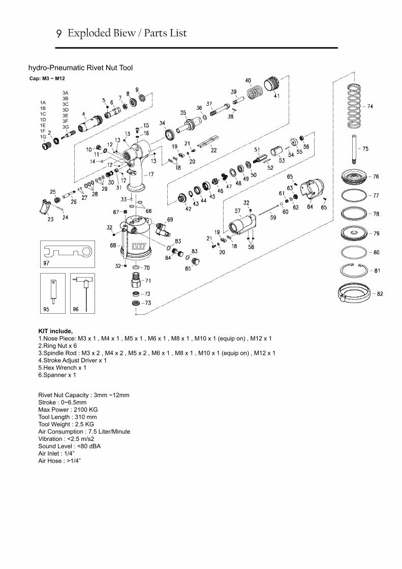
Exploded Biew / Parts List
hydro-Pneumatic Rivet Nut Tool
Rivet Nut Capacity : 3mm ~12mmStroke : 0~6.5mmMax Power : 2100 KGTool Length : 310 mmTool Weight : 2.5 KGAir Consumption : 7.5 Liter/Minute Vibration : <2.5 m/s2 Sound Level : <80 dBAAir Inlet : 1/4”Air Hose : >1/4”
KIT include,1.Nose Piece: M3 x 1 , M4 x 1 , M5 x 1 , M6 x 1 , M8 x 1 , M10 x 1 (equip on) , M12 x 12.Ring Nut x 63.Spindle Rod : M3 x 2 , M4 x 2 , M5 x 2 , M6 x 1 , M8 x 1 , M10 x 1 (equip on) , M12 x 1 4.Stroke Adjust Driver x 15.Hex Wrench x 16.Spanner x 1

NO. PART NO. DESCRIPTION Q'TY1A PB-2501P01A Head M3 11B PB-2501P01B Head M4 11C PB-2501P01C Head M5 11D PB-2501P01D Head M6 11E PB-2501P01E Head M8 11F PB-2501P01F Head M10 11G PB-2501P01G Head M12 (Optional) 12 PB-2501T02 Ring Nut (6 pcs) 1 SET
3A PB-2501P03A Tie Rod M3 13B PB-2501P03B Tie Rod M4 13C PB-2501P03C Tie Rod M5 13D PB-2501P03D Tie Rod M6 13E PB-2501P03E Tie Rod M8 13F PB-2501P03F Tie Rod M10 13G PB-2501P03G Tie Rod M12 (Optional) 14 PB-2501P04 Outer Cone 15 PB-2501P05 Screw 16 PB-2501P06 Tie Rod Holder 17 PB-2501P07 Hex. Nut 18 PB-2501P08 Ring Bolt 19 PB-2501P09 Oil Seal 1
10 PB-2501P10 Cap Screw 111 PB-2501P11 Washer Seal 112 PB-2501T12 Screw (3 pcs) 1 SET13 PB-2501T13 Screw (3 pcs) 1 SET14 PB-2501P14 115 PB-2501P15 Screw 116 PB-2501P16 Washer Seal 117 PB-2501P17 Handle Casing 118 PB-2501T18 O-Ring (6 pcs) 1 SET19 PB-2501T19 Pipe Guide (4 pcs) 1 SET20 PB-2501T20 Washer (2 pcs) 1 SET21 PB-2501T21 Screw (2 pcs) 1 SET22 PB-2501T22 Air Pipe (2 pcs) 1 SET23 PB-2501P23 Trigger 124 PB-2501P24 Pin 125 PB-2501P25 Bolt 126 PB-2501P26 Valve Stem 127 PB-2501T27 O-Ring (2 pcs) 1 SET28 PB-2501T28 Valve Seal (3 pcs) 1 SET29 PB-2501T29 O-Ring (3 pcs) 1 SET30 PB-2501P30 Valve 131 PB-2501P31 Valve Stem Retainer 132 PB-2501T32 Screw (3 pcs) 1 SET33 PB-2501P33 Pin 134 PB-2501P34 Oil Seal 135 PB-2501P35 Hydraulic Piston 136 PB-2501P36 Washer 137 PB-2501P37 Drive Bolt 138 PB-2501P38 Spring Pin 139 PB-2501P39 Coupler 140 PB-2501P40 Spring 141 PB-2501P41 Stroke Adjuster 142 PB-2501P42 Coupling Bolt 143 PB-2501P43 Snap Ring 1
NO. PART NO. DESCRIPTION Q'TY44 PB-2501P44 Ball Bearing 145 PB-2501P45 Ring Gear 146 PB-2501P46 Gear Carrier 147 PB-2501T47 Planet Gear (3 pcs) 1 SET48 PB-2501P48 Spacer 149 PB-2501P49 Ball Bearing 150 PB-2501P50 Front end plate 151 PB-2501P51 Rotor 152 PB-2501T52 Blade (5 pcs) 1 SET53 PB-2501P53 Cylinder 154 PB-2501P54 Pin 155 PB-2501P55 Rear end plate 156 PB-2501P56 Ball Bearing 157 PB-2501P57 Motor Housing 158 PB-2501T58 Screw (2 pcs) 1 SET59 PB-2501P59 Valve tappet 160 PB-2501P60 Nylon Ball 161 PB-2501P61 Spring 162 PB-2501P62 O-Ring 163 PB-2501P63 Cap Screw 164 PB-2501P64 Rear cover 165 PB-2501T65 Screw (2 pcs) 1 SET66 PB-2501T66 O-Ring (2 pcs) 1 SET67 PB-2501P67 Screw 168 PB-2501P68 Pneumatic cylinder 169 PB-2501P69 Swivel inlet 170 PB-2501P70 O-Ring 171 PB-2501P71 Piston rod guide 172 PB-2501P72 Oil Seal 173 PB-2501P73 Ring Bolt 174 PB-2501P74 Spring 175 PB-2501P75 Piston rod 176 PB-2501P76 Pneumatic Piston 177 PB-2501P77 Guide ring 178 PB-2501P78 Oil seal 179 PB-2501P79 Bottom cap 180 PB-2501P80 O-Ring 181 PB-2501P81 Snap Ring 182 PB-2501P82 Rubber Base (2 pcs) 183 PB-2501T83 O-Ring 1 SET84 PB-2501P84 Plug 185 PB-2501P85 Valve Cap 195 PB-2501P95 Stroke Regulator 196 PB-2501P96 Hex. Wrench 197 PB-2501P97 Spanner 1
Hydro-Pneumatic Rivet Nut Tool (M8~M12)
Part List Item No : PB-2501