Embed Size (px)
Citation preview
Utilization of Waste Rock fromOil Shale Mining
TARMO TOHVER
P R E S S
THESIS ON POWER ENGINEERING,ELECTRICAL ENGINEERING, MINING ENGINEERING D48
ENERGEETIKA. ELEKTROTEHNIKA. M ENDUS D48Ä
P levkivi kaevandamis
rikastamisj kide kasutamine
õ - jaää
TARMO TOHVER

4
5
CONTENTS
1 TERMS ........................................................................................................ 8
2 LIST OF PUBLICATIONS ......................................................................... 9
3 INTRODUCTION ..................................................................................... 10
4 ACKNOWLEDGEMENT ......................................................................... 12
5 METHODS ................................................................................................ 13
6 GEOLOGICAL SITUATION ................................................................... 13
7 MINING TECHNOLOGY ........................................................................ 14
7.1 OPENCAST MINING ...................................................................... 14
7.2 UNDERGROUND MINING ............................................................ 15
7.3 SEPARATION .................................................................................. 15
8 WASTE ROCK FROM OIL SHALE MINING ....................................... 15
8.1 TYPES OF WASTE ROCK .............................................................. 16
8.2 PROPERTIES OF WASTE ROCK .................................................. 16
9 AGGREGATE PRODUCTION TECHNOLOGY .................................... 18
9.1 PROCESS PLANNING .................................................................... 18
9.2 HIGH-SELECTIVE MINING TECHNOLOGY .............................. 22
9.2.1 AGGREGATE PRODUCTION WITH SURFACE MINER .... 22
9.2.2 AGGREGATE PRODUCTION IN CRUSHING AND SCREENING PLANT ............................................................................... 23
9.3 SELECTIVE AND BULK MINING TECHNOLOGY .................... 23
10 PROPERTIES OF OIL SHALE WASTE ROCK AGGREGATE ........ 23
10.1 GEOMETRICAL PROPERTIES ...................................................... 23
10.2 PHYSICAL PROPERTIES ............................................................... 24
10.2.1 RESISTANCE TO FRAGMENTATION ................................. 24
6
10.2.2 WATER ABSORPTION ........................................................... 27
10.2.3 RESISTANCE TO FREEZING AND THAWING ................... 27
11 UTILIZATION OF WASTE ROCK ..................................................... 32
11.1 UTILIZATION OF WASTE ROCK IN CIVIL ENGINEERING AND ROAD BUILDING .............................................................................. 32
11.2 AGGREGATE FOR BACKFILLING THE MINED AREAS ......... 33
12 RESULTS .............................................................................................. 35
13 DISCUSSION ....................................................................................... 35
14 CONCLUSIONS AND RECOMMENDATIONS ................................ 36
15 Appendixes ............................................................................................ 51
Appendix 1 The oil shale stratum [46] ............................................................. 52
Appendix 2 The Estonian Oil shale deposit [47] ............................................... 53
Appendix 3 Oil shale separation sheet, “Estonia” mine [7] .............................. 54
Appendix 4 Properties of oil shale waste rock after separation ........................ 55
Appendix 5 Properties of waste rock aggregate in accordance with GOST...... 56
Appendix 6 Bulk density of aggregate, kg * 103/m3 ......................................... 57
Appendix 7 Properties of aggregates in unbound mixtures for bases ............... 58
Appendix 8 Samples of waste rock aggregate………………………………..59
Figure 1 Heating value of waste rock depending on particle size ..................... 17
Figure 2 The three-stage crushing plant in “Aidu” open cast............................ 20
Figure 3 Risk management process ................................................................... 21
Figure 4 Event tree ............................................................................................ 22
Figure 5 Resistance to fragmentation depending on number of crushing stages
........................................................................................................................... 24
7
Figure 6 Resistance to fragmentation depending on particle size ..................... 25
Figure 7 Correlation between resistance to fragmentation and destructibility .. 26
Figure 8 Resistance to freezing and thawing depending on resistance to
fragmentation .................................................................................................... 26
Figure 9 Water absorption depending on number of crushing stages ............... 27
Figure 10 Resistance to freezing and thawing depending on number of crushing
stages ................................................................................................................. 28
Figure 11 Resistance to freezing and thawing depending on particle size ........ 29
Figure 12 Heating value and resistance to freezing and thawing depending on
particle size ........................................................................................................ 30
Figure 13 Resistance to freezing and thawing depending on water absorption 31
Figure 14 Frost-resistance (in accordance with GOST 8269) compared with
resistance to freezing and thawing (in accordance with EN 1367-1) ................ 32
Table 1 Classification of rocks according to crushability [12] .......................... 18
Table 2 Classification of rocks according to abrasiveness [12] ........................ 18
Table 3 Types of crusher and reduction ratio [11] ............................................ 19
8
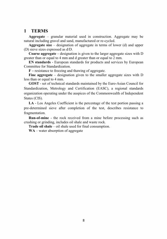
1 TERMS Aggregate – granular material used in construction. Aggregate may be
natural including gravel and sand, manufactured or re-cycled. Aggregate size – designation of aggregate in terms of lower (d) and upper
(D) sieve sizes expressed as d/D. Coarse aggregate – designation is given to the larger aggregate sizes with D
greater than or equal to 4 mm and d greater than or equal to 2 mm. EN standards - European standards for products and services by European
Committee for Standardization. F – resistance to freezing and thawing of aggregate. Fine aggregate – designation given to the smaller aggregate sizes with D
less than or equal to 4 mm. GOST - set of technical standards maintained by the Euro-Asian Council for
Standardization, Metrology and Certification (EASC), a regional standards
organization operating under the auspices of the Commonwealth of Independent
States (CIS).
LA - Los Angeles Coefficient is the percentage of the test portion passing a
pre-determined sieve after completion of the test, describes resistance to
fragmentation.
Run-of-mine - the rock received from a mine before processing such as crushing or grinding, includes oil shale and waste rock.
Trade oil shale – oil shale used for final consumption. WA – water absorption of aggregate
9
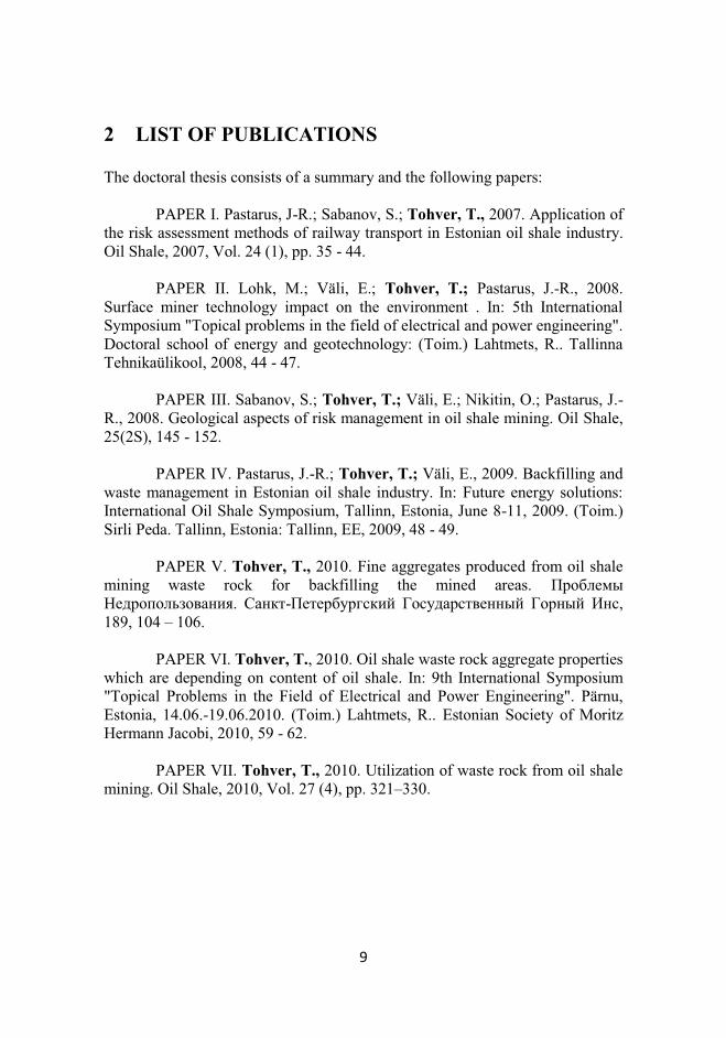
2 LIST OF PUBLICATIONS The doctoral thesis consists of a summary and the following papers: PAPER I. Pastarus, J-R.; Sabanov, S.; Tohver, T., 2007. Application of the risk assessment methods of railway transport in Estonian oil shale industry. Oil Shale, 2007, Vol. 24 (1), pp. 35 - 44. PAPER II. Lohk, M.; Väli, E.; Tohver, T.; Pastarus, J.-R., 2008. Surface miner technology impact on the environment . In: 5th International Symposium "Topical problems in the field of electrical and power engineering". Doctoral school of energy and geotechnology: (Toim.) Lahtmets, R.. Tallinna Tehnikaülikool, 2008, 44 - 47. PAPER III. Sabanov, S.; Tohver, T.; Väli, E.; Nikitin, O.; Pastarus, J.-R., 2008. Geological aspects of risk management in oil shale mining. Oil Shale, 25(2S), 145 - 152.
PAPER IV. Pastarus, J.-R.; Tohver, T.; Väli, E., 2009. Backfilling and waste management in Estonian oil shale industry. In: Future energy solutions: International Oil Shale Symposium, Tallinn, Estonia, June 8-11, 2009. (Toim.) Sirli Peda. Tallinn, Estonia: Tallinn, EE, 2009, 48 - 49.
PAPER V. Tohver, T., 2010. Fine aggregates produced from oil shale mining waste rock for backfilling the mined areas. Проблемы Недропользования. Санкт-Петербургский Государственный Горный Инс, 189, 104 – 106. PAPER VI. Tohver, T., 2010. Oil shale waste rock aggregate properties which are depending on content of oil shale. In: 9th International Symposium "Topical Problems in the Field of Electrical and Power Engineering". Pärnu, Estonia, 14.06.-19.06.2010. (Toim.) Lahtmets, R.. Estonian Society of Moritz Hermann Jacobi, 2010, 59 - 62. PAPER VII. Tohver, T., 2010. Utilization of waste rock from oil shale mining. Oil Shale, 2010, Vol. 27 (4), pp. 321–330.
10
3 INTRODUCTION
The Estonian oil shale deposit stretches from the Russian border at the Narva River 130 km west along the Gulf of Finland (APPENDIX 2). Oil shale reserves are estimated to be approximately four billion tonnes. Oil shale is a yellowish-brown, relatively soft sedimentary rock of low density that contains a significant amount of organic matter and carbonate fossils. Oil shale layers are intercalated with limestone layers. The thickness of the oil shale seam, without partings, ranges between 1.7 m and 2.3 m. The compressive strength for oil shale is 20 MPa to 40 MPa compared to 40 MPa to 80 MPa for limestone. The density of oil shale is between 1400 kg/m3 and 1800 kg/m3 and that of limestone is between 2200 kg/m3 and 2600 kg/m3. The heating value of oil shale deposit is fairly consistent across the deposit. There is a slight decrease in heating value from the north to the south, and from the west to the east across the area. Oil shale resources of Estonia are state-owned and lie in the Estonian deposit which is of national importance. The state has issued mining licenses to the mines and pitches allowing them to perform mining works. 85% of mined oil shale is used for generation of electric power and a large share of thermal power, and about 15% goes for shale oil production. About 95% of electric power is produced from Estonian oil shale. Power stations consume oil shale with net heating value Qr
i = 8.4 ... 11 MJ/kg. Net heating values of oil shale used for retorting and chemical processing must be approximately 11.4 MJ/kg [PAPER II].
Annually circa 15 million tonnes of oil shale are extracted, 50% is mined in underground mines and 50% is mined in surface mines. Oil shale waste rock (limestone, marlstone or dolostone) is produced during extraction, from reject material from a separation plant and material from crushing and sizing operations in aggregate production. Major part of waste rock from opencast mine is deposited and mining site is restored. Waste rock from underground mine is piled up in waste rock dumps near to mines and the deposited amount is about 5 million tonnes per year. In some cases dumps have been designed for recreational purposes. Total amount of already deposited waste rock is over 100 million tonnes. Crushed waste rock from separation plant is produced in classes 25/100 and 100/300 mm and is utilized as a fill soil and in road building. Aggregate produced from waste rock is utilized in road building and in civil engineering [PAPER VII].
The actuality of the thesis lies in the following:
Removal of already deposited land areas; Utilization of waste rock helps to exploit natural resources more rational
ways; ys Utilization of abandoned waste rock helps to improve public opinion,
because local people are usually against new mines. Reduction of deposited waste rock in environment.
11
Extraction taxes on mining permit and discharge of waste in Estonia are continually increasing. Charge for the extraction of low-quality limestone belonging to the state in 2006 was 0.45 Euro per m3, but in 2015 it will be 1.25 Euro per m3 [1] and charge rates for oil shale waste rock disposal in 2006 were 0.38 Euro per tonne, but in 2011 are 0.76 Euro per tonne [2]. Therefore, more rational ways to exploit natural resources of constructional materials and utilize already mined and deposited waste rock is needed.
Waste rock utilization has worldwide experience. Waste rock utilisation in Estonia started in 1957 when a base for the road between towns Jõhvi and Kohtla-Järve was built with waste rock from underground mine Kurkuse. In 1971 the geometrical and physical properties for waste rock aggregates from “Viru”, “Tammiku” and “Ahtme” underground mines were determined.
Studies on utilization of aggregate produced from the oil shale mining waste rock started in 1989 under direction of Emeritus Professor Alo Adamson [3, 4]. Aggregate was produced from waste rock from different separation technologies and using selective mining with drilling and blasting technology from seam E/C in “Aidu” and “Narva” open-cast. The conclusion was made that aggregate has destructibility M400 – M600 and frost resistance 25 cycles and aggregate is usable in road building for base construction where traffic volume is low and in concrete with compressive strength M300 in accordance with GOST 10268 and frost-resistance F100 - F200 in accordance with GOST 10060 [3]. In order to utilize aggregate in road building and civil engineering, the maximum limit of water absorption 5% was determined. Water absorption is correlated with frost resistance and therefore determination of water absorption is a rapid way to assess the frost resistance of aggregate. Studies have shown that fine undersized aggregate can be utilized for backfilling the mined areas where the ashes from powdered combustion are used as a binder.
It was determined that impact crusher is the best type of crusher using different schemes of crushing and screening. Impact crusher uses selective crushing, a method that liberates weak oil shale particles from hard limestone waste rock.
The first crushing and screening plant with two stage impact crushers was installed in “Aidu” open cast. The productivity of the plant in 1996 was 350 tonnes of aggregate per day, yield of the aggregate from waste rock 40% and organic matter content in aggregate was 4.3 – 7.4% [4].
In 2001/02 aggregate from waste rock from “Estonia” underground mine and “Aidu” open cast was produced at a two-stage crushing plant with impact crushers. Tests showed that aggregate from waste rock can be produced in accordance with EN requirements. The resistance to fragmentation LA ≤ 35% and resistance to freezing and thawing F = 4 … 14%. The conclusion was made that in order to increase the resistance of coarse aggregate, a third impact crusher shall be installed in order to crush additionally particle size 20 mm retained on screen.
12
In 2006 a three stage crushing plant with impact crushers was installed in a “Aidu” open cast. Properties of produced aggregate are as follows: the resistance to fragmentation LA ≤ 35% and resistance to freezing and thawing F ≤ 4%. The aggregate is utilized in road building where traffic volume is low.
The main problem of the properties of aggregate is low resistance to fragmentation and resistance to freezing and thawing which is caused by fine and weak oil shale particles [PAPER VI]. It is essential to find ways to extract oil shale and limestone separately. A highly-selective mining method may be applied in open cast with Surface Miner [PAPER II].
Waste rock which is not usable in civil engineering and road building may be used for backfilling already mined areas [PAPER IV and PAPER V]. There are ongoing studies to find out possibilities to utilize ashes formed in circulating fluidized bed with oil shale mining waste rock aggregate. Backfilling helps us to manage geological risks [PAPER III]. Risk management method as a tool is suitable for the evaluation other mining activities [PAPER I].
The objectives of this study are: 1) Determination of aggregate property, which classifies areas of utilization; 2) Determination of aggregate properties dependence on content of oil shale
particles; 3) Determination of aggregate properties dependence on number of crushing
cycles; 4) Determination of aggregates properties correlation in accordance with
GOST and EN; 5) Determination of aggregates maximum heating value, which allows to
utilise aggregate in civil engineering and road building; 6) Determination of aggregates maximum water absorption value, which
allows to utilise aggregate in civil engineering and road building; 7) Determination of areas utilisation for different limestone interlayers; 8) Determination of areas utilisation for different types of waste rock;
4 ACKNOWLEDGEMENT
I am grateful to Professor Ingo Valgma and Emeritus Professor Alo Adamson for their supervision and valuable informative suggestions.
Special thanks to Associate Professor Jüri-Rivaldo Pastarus, Emeritus Professor Enno Reinsalu and Sergei Sabanov for their support and help.
I want to thank my colleagues at Estonian Energy Mining Company Oleg Nikitin, Erik Väli, Kalmer Sokman, Ljudmilla Kolotõgina, Margus Loko, Erkki Kaisla, Robert Karpelin, Illimar Parts, Martin Lohk, Evelin Krekker, Andrus Paat, Pavel Onuchak, Ants Vannus, Märt Trummar, Alla Zaitseva, Vladimir Kašin, Juri Lutkov, Aarne Nõmberg, Urmas Janno and Terje Lentso for their practical help in data collection.
Special thanks to my family for their care and patience.
13
The research was supported by Estonian Science Foundation grants no 6558 “Concept and methods of risk management in mining” and no 7499 „Conditions of sustainable mining“.
5 METHODS
In the course of this study properties of waste rock and waste rock aggregate from different underground and open cast mines have been studied. Data were available from 2001 to 2008. In 2008 this study was started and with the assistance of multistage selective crushing technology numerous samples of waste rock and waste rock aggregate have been taken from different mines, from different layers, tested in laboratory. In 2008, the construction of a two-stage crushing plant started in “Estonia” underground mine. Responsibility of the author was quality management and sales of aggregate. Data from 2001 to 2010 (APPENDIX 8) have been statistically analysed and correlation between properties and applied technologies has been studied. A risk management tool has been applied. Conclusions and recommendations have been made.
6 GEOLOGICAL SITUATION
The Estonian oil shale – kukersite – lies between limestone layers of the Upper Ordovician Kukruse Stage Viivikonna Formation [5]. The commercial oil shale bed consists of seven kukersite layers (A, A’, B, C, D, E, F1) and six limestone layers (A/A’, A’/B, B/C, C/D, D/E, E/F1). Thickness of oil shale layers differs from 5 cm to 60 cm. Most of them, layers B, C, E and F1 consists of lens-shaped fine concretions of kerogenic limestone. Limestone in concretions is yellowish bright-gray and consists of up to 10 % organic matter.
The thickest limestone layers are A’/B and C/D with thickness from 10 to 30 cm. Boundaries of these layers are sufficiently straight, organic matter content is usually lower than 5%. Other interlayers consist of organic matter up to 12%. They have variable thickness and sometimes look like stretched lens-shaped concretions. Layers A/A’ and E/F1 are very thin, from 1 to 5 cm and sometimes inseparable.
Limestone layer A/A’ is a layer with thickness up to 5 cm and consists of kerogenic limestone concretions with organic matter content from 3% to 8%. Sometimes layer A/A’ does not exist.
Limestone layer A’/B called as a “blue limestone” is a blue-green clayey and a little kerogenic limestone or marlstone. Boundaries are clear and straight. The thickness of layer varies from 6 cm in north-west side to 10 cm in south-east side of the deposit. Organic matter content varies from 8% to 2% in the same direction. Content of carbonate matter is stable from 65% to 75% and content of terrigenic material is from 20% to 32%.
14
Limestone layer B/C called as a “fist” is a yellowish-gray kerogenic limestone. Content of organic matter is very stable from 8% to 12%. Content of carbonate matter is 75% to 85% and content of terrigenic material is from 10% to 15%. In the west side of the deposit, the thickness of the layer is lower than 10 cm and in east or south side, the thickness is from 15 cm to 20 cm.
Limestone layer C/D called as “double limestone” is the thickest limestone layer with clear boundaries and with bright gray colour. The thickness varies from 20 cm to 30 cm. Only in the north-west side of the deposit, the thickness is lower than 20 cm and in the south-east side of the deposit, the thickness is greater than 30 cm. Organic matter content is lower than 2% and it is concentrated on the boundaries. Content of carbonate matter is from 82% to 86% and content of terrigenic material is from 12% to 16%.
Limestone layer D/E called as “pink limestone” with clear boundaries and its thickness is up to 15 cm in north-west side of the deposit and declines in to south-east direction where the thickness is from 6 cm to 8 cm. Colour of the layer is pink- bright-gray. Organic matter content varies from 4% to 10% in north-west direction.
Limestone layer E/F1 is characterized by lens-shaped concretions with thickness from 3 cm to 5 cm. Limestone is kerogenic, yellowish gray with organic matter content from 4% to 8% [6].
7 MINING TECHNOLOGY
7.1 OPENCAST MINING
Different types of mining technology are used in the deposit. “Aidu” and
“Narva” opencast mines use stripping with draglines, bucket 10 – 15 m3. Both the overburden and the bed are broken up by blasting. Stripping is done with smaller excavators in opencasts with thin overburden using front end loaders and hydraulic excavators. The overburden is transported with front end loaders and trucks.
Bulk extraction of all beds (layers F-A) is performed in the Aidu open cast where a separation plant is in operation. Selective extraction of three layers of seams is used in the Narva and also in the Aidu open cast. The upper (layers F/E) and the lower (layers B/C) seams are extracted as a run of mine, the middle seam (interlayers D/C and F/E) is shoved or dozed into the mined-out area. If the bed is broken mechanically, with ripper dozers, the oil shale can be extracted selectively and completely. Provided layers A and D are taken into run of mine, which were lost in partial selective extraction.
A Highly- selective extraction is used in Põhja-Kiviõli and in Narva opencast, with a milling cutter of Surface Miner from the Wirtgen Company. Run of mine is loaded into vehicles with front shovel excavators or front end
15
loaders. Run of mine is transported with trucks. It is delivered to consumers by railway, highway trucks and dump trucks. The surface mining is finished by reclamation of the mined out area [7]. Surface miner can cut limestone and oil-shale seams separately and more exactly than rippers (2…7 cm) with deviations about one cm [PAPER II].
7.2 UNDERGROUND MINING
Underground mining technology uses room and pillar system. The main
characteristics are as follows: § Blocks of rooms, formed by up to 10 m long working faces; § The roof and the mined out land are supported with pillars of not
extracted oil shale (averaging 25% of the reserve); § The ground surface does not subside; § The direct immediate roof of the rooms is anchored to the upper rock
layers. Longwall mining has also been used, where the bed was mined with a coal
cutting shearer-loader. The roof was temporarily supported by hydraulic support. If the mining is performed with the shearer, layers C-A were extracted, so in reality it was a selective extraction. This mining method was more productive, but much more capital-intensive and the changes in land surface were noticeable [7].
7.3 SEPARATION
Oil shale run of mine separation has been used for the benefit of the shale oil
processing industry. Vertical retort technology of oil processing can use only oil shale lumps of size from 25 to 125 mm, because the processed raw material must have sufficient gas permeability to ensure the separation process in the retort. Oil shale is separated in separation plant out of coarse (>25 mm) run of mine pieces. This takes place in heavy medium where pieces of limestone interlayer lumps and concretions of run of mine sink, and oil shale floats on the surface. The fine oil shale, sifted out of run of mine before separation, goes to power plants. The waste rock separated from run of mine, which proportion is approximately 40%, is suitable for production of construction materials (APPENDIX 3) [7].
8 WASTE ROCK FROM OIL SHALE MINING
In order to achieve required heating value of trade oil shale, oil shale is extracted selectively, with a highly-selective method or oil shale is separated from run of mine in a separation plant. ‘
16
8.1 TYPES OF WASTE ROCK
There are different types of waste products from mining and separation activities [8]. In Estonian oil shale mining, waste rock products can be divided as follows:
§ Blasted and broken limestone is removed during mining operations in order to expose the oil shale. In surface mining, the waste rock is deposited together with overburden and is used for mining site restoration. Material is not homogeneous, the size of the waste rock is variable, pieces of rock can be up to 1.5 m in size.
§ Reject material which is also called refuse and results from separation and washing of oil shale. This is composed principally of limestone or marlstone, some sand and clay, and amounts of oil shale, depending on the efficiency of the separation plant operation. Refuse is produced and disposed of in a coarse form. Fractions of waste rock are 25/100 and 100/300 mm. Fine refuse is settled and then mixed with trade oil shale.
§ Unwanted material from crushing and sizing operations in aggregate production.
8.2 PROPERTIES OF WASTE ROCK
Petrographic description of the waste rock: § Finegrained organo-clastic blue-gray clayey dolomitisated limestone
with content of calcite and dolomite from 80 to 85%; § Finegrained organo-clastic bituminisated yellow clayey limestone with
content of calcite and dolomite from 73 to 82%. Compared with first type of rock the content of kerogenic matter is higher and it is less dolomitisated [3].
Oil shale waste rock does not have any other harmful additives than oil shale. Content of waste rock from “Aidu” open cast [3]:
Humidity – 1.5 – 5.3%; Heating value determined in a calometric bomb Qd
b = 1.44 – 3.1 MJ/kg; Content of oil shale – 5.0 – 10.5%; Content of organic matter – 4.3 – 8.9%; Content of ash – 57.1 – 60.1%; Density – 2380 – 2590 kg/m3; Bulk density – 1010 – 1240 kg/m3; Porosity – 45.5 – 56.1%; Porosity of grains – 6.5 – 16.6%; Water absorption – 3.3 – 4.4%; Crushability (in accordance with French standard NF P-18-579) – 55%; Abrasiveness (in accordance with French standard NF P-18-579) - 84 g/t
17
Chemical content: § SiO2 – 4.5 – 11.3%; § Al2O3 – 1.72 – 2.93%; § FeO – 0.91 – 2.93%; § CaO – 35.3 – 42.7%; § MgO – 1.1 – 2.3%. CaCO3 + MgCO3 – 75.1 – 85.2%.
The compressive strength of the layers D/C and C/B is from 73 to 84 MPa and of other layers is from 40 to 62 MPa [3].
In selective extraction, where seams are shoved or dozed into the mined-out area, the properties of waste rock depend on those layers and how clearly the layers are extracted.
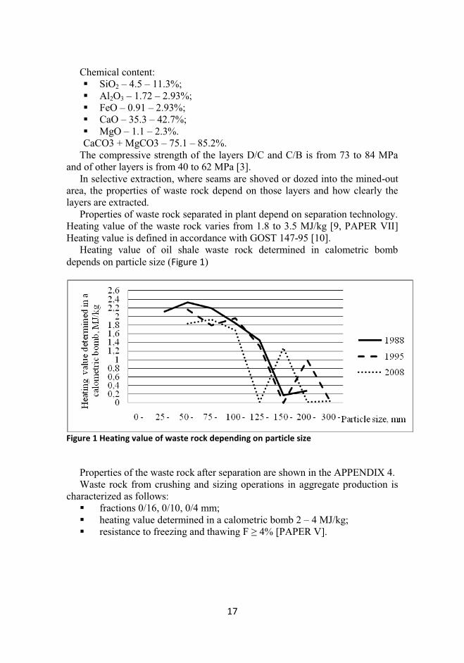
Properties of waste rock separated in plant depend on separation technology. Heating value of the waste rock varies from 1.8 to 3.5 MJ/kg [9, PAPER VII] Heating value is defined in accordance with GOST 147-95 [10].
Heating value of oil shale waste rock determined in calometric bomb depends on particle size (Figure 1)
Figure 1 Heating value of waste rock depending on particle size
Properties of the waste rock after separation are shown in the APPENDIX 4. Waste rock from crushing and sizing operations in aggregate production is
characterized as follows: § fractions 0/16, 0/10, 0/4 mm; § heating value determined in a calometric bomb 2 – 4 MJ/kg; § resistance to freezing and thawing F ≥ 4% [PAPER V].
18
9 AGGREGATE PRODUCTION TECHNOLOGY
9.1 PROCESS PLANNING
Production technology depends on application of aggregate and properties of
the waste rock. The crushing process planning depends on rock fraction, moisture content, density, crushability and abrasiveness [11].
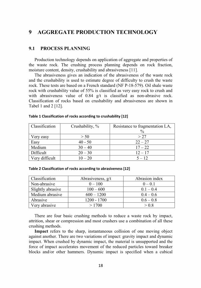
The abrasiveness gives an indication of the abrasiveness of the waste rock and the crushability is used to estimate degree of difficulty to crush the waste rock. These tests are based on a French standard (NF P-18-579). Oil shale waste rock with crushability value of 55% is classified as very easy rock to crush and with abrasiveness value of 0.84 g/t is classified as non-abrasive rock. Classification of rocks based on crushability and abrasiveness are shown in Tabel 1 and 2 [12].
Table 1 Classification of rocks according to crushability [12]
Classification Crushability, % Resistance to fragmentation LA, %
Very easy > 50 > 27 Easy 40 - 50 22 – 27 Medium 30 – 40 17 – 22 Difficult 20 – 30 12 – 17 Very difficult 10 – 20 5 – 12
Table 2 Classification of rocks according to abrasiveness [12]
Classification Abrasiveness, g/t Abrasion index Non-abrasive 0 – 100 0 – 0.1 Slightly abrasive 100 – 600 0.1 – 0.4 Medium abrasive 600 – 1200 0.4 – 0.6 Abrasive 1200 - 1700 0.6 – 0.8 Very abrasive > 1700 > 0.8
There are four basic crushing methods to reduce a waste rock by impact,
attrition, shear or compression and most crushers use a combination of all these crushing methods.
Impact refers to the sharp, instantaneous collision of one moving object against another. There are two variations of impact: gravity impact and dynamic impact. When crushed by dynamic impact, the material is unsupported and the force of impact accelerates movement of the reduced particles toward breaker blocks and/or other hammers. Dynamic impact is specified when a cubical
19
particle is needed, when finished, product must be well graded and must meet intermediate sizing specifications, when rocks must be broken along natural cleavage lines in order to free and separate undesirable inclusions, if materials are too hard and abrasive for hammermills, but where jaw crushers cannot be used because of particle shape requirements, high moisture content or capacity.
Attrition is reduction of materials by scrubbing it between two hard surfaces. Attrition is most useful when material is friable or not too abrasive and when closed-circuit system is not desirable to control top size.
Shear consists of a trimming or cleaving action rather than the rubbing action associated with attrition. Shear crushing is needed when material is somewhat friable and has relatively low silica content, for primary crushing with a reduction ratio of 6 to 1, when a relatively coarse product is desired.
Compression is crushing done between two surfaces, with the work being done by one or both surfaces. Jaw crushers with this method of compression are suitable for reduction of extremely hard and abrasive rock. Compression should be used if the material is hard and tough, if the material is abrasive, if the material is not sticky, where the finished product is to be relatively coarse, if the material will break cubically [13].
For primary and secondary stage of crushing, either compressive type of crusher or impact crusher (horizontal shaft) can be selected. Impact crushers perform well in high crushability and low abrasiveness applications and compressive type of crushers perform well in hard rock and high abrasiveness applications. In tertiary stage of crushing either impact crusher or cone crusher can be selected. For high crushability and low abrasiveness, such as for limestone vertical or horizontal shaft impact crushers can be used. Usage of cone crushers is limited because size of particles has to be bigger than 5 mm and moisture content equal to or lower than 3%.
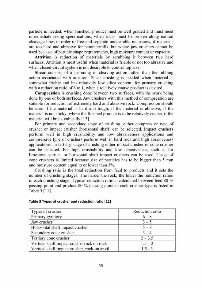
Crushing ratio is the total reduction from feed to products and it sets the number of crushing stages. The harder the rock, the lower the reduction ration in each crushing stage. Typical reduction rations calculated between feed 80-% passing point and product 80-% passing point in each crusher type is listed in Table 3 [11].
Table 3 Types of crusher and reduction ratio [11]
Types of crusher Reduction ratio Primary gyratory 6 – 8 Jaw crusher 3 – 5 Horizontal shaft impact crusher 5 – 8 Secondary cone crusher 3 – 4 Tertiary cone crusher 2 – 3.5 Vertical shaft impact crusher rock on rock 1.5 – 2 Vertical shaft impact crusher, rock-on anvil 1.5 - 3
20
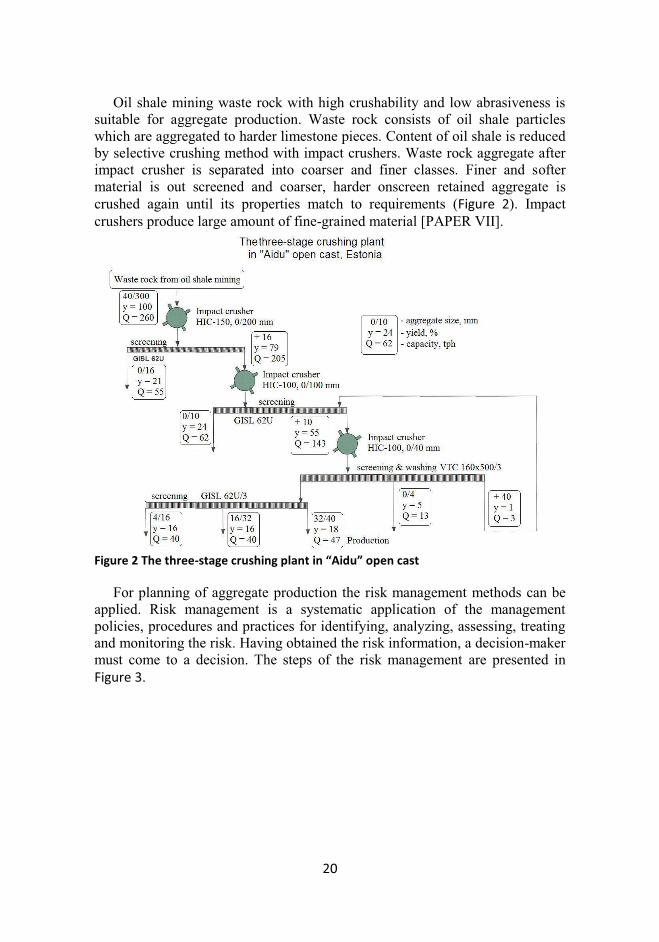
Oil shale mining waste rock with high crushability and low abrasiveness is suitable for aggregate production. Waste rock consists of oil shale particles which are aggregated to harder limestone pieces. Content of oil shale is reduced by selective crushing method with impact crushers. Waste rock aggregate after impact crusher is separated into coarser and finer classes. Finer and softer material is out screened and coarser, harder onscreen retained aggregate is crushed again until its properties match to requirements (Figure 2). Impact crushers produce large amount of fine-grained material [PAPER VII].
Figure 2 The three-stage crushing plant in “Aidu” open cast
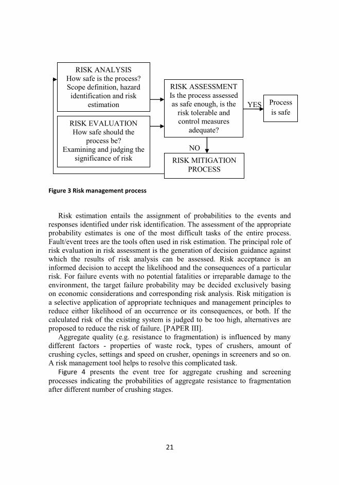
For planning of aggregate production the risk management methods can be applied. Risk management is a systematic application of the management policies, procedures and practices for identifying, analyzing, assessing, treating and monitoring the risk. Having obtained the risk information, a decision-maker must come to a decision. The steps of the risk management are presented in Figure 3.
21
YES NO Figure 3 Risk management process
Risk estimation entails the assignment of probabilities to the events and
responses identified under risk identification. The assessment of the appropriate probability estimates is one of the most difficult tasks of the entire process. Fault/event trees are the tools often used in risk estimation. The principal role of risk evaluation in risk assessment is the generation of decision guidance against which the results of risk analysis can be assessed. Risk acceptance is an informed decision to accept the likelihood and the consequences of a particular risk. For failure events with no potential fatalities or irreparable damage to the environment, the target failure probability may be decided exclusively basing on economic considerations and corresponding risk analysis. Risk mitigation is a selective application of appropriate techniques and management principles to reduce either likelihood of an occurrence or its consequences, or both. If the calculated risk of the existing system is judged to be too high, alternatives are proposed to reduce the risk of failure. [PAPER III].
Aggregate quality (e.g. resistance to fragmentation) is influenced by many different factors - properties of waste rock, types of crushers, amount of crushing cycles, settings and speed on crusher, openings in screeners and so on. A risk management tool helps to resolve this complicated task.
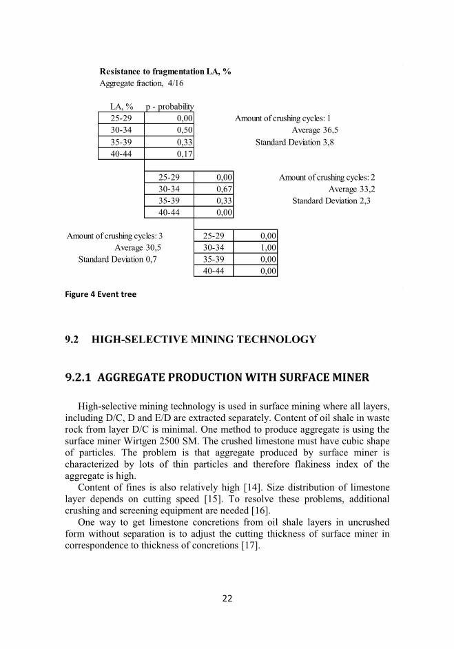
Figure 4 presents the event tree for aggregate crushing and screening processes indicating the probabilities of aggregate resistance to fragmentation after different number of crushing stages.
RISK ANALYSIS How safe is the process? Scope definition, hazard identification and risk
estimation
RISK EVALUATION How safe should the
process be? Examining and judging the
significance of risk
RISK ASSESSMENT Is the process assessed as safe enough, is the
risk tolerable and control measures
adequate?
Process
is safe
RISK MITIGATION PROCESS
22
Resistance to fragmentation LA, %
Aggregate fraction, 4/16
LA, % p - probability
25-29 0,00 Amount of crushing cycles: 130-34 0,50 Average 36,5
35-39 0,33 Standard Deviation 3,8
40-44 0,17
25-29 0,00 Amount of crushing cycles: 230-34 0,67 Average 33,2
35-39 0,33 Standard Deviation 2,340-44 0,00
Amount of crushing cycles: 3 25-29 0,00Average 30,5 30-34 1,00
Standard Deviation 0,7 35-39 0,0040-44 0,00
Figure 4 Event tree
9.2 HIGH-SELECTIVE MINING TECHNOLOGY
9.2.1 AGGREGATE PRODUCTION WITH SURFACE MINER
High-selective mining technology is used in surface mining where all layers,
including D/C, D and E/D are extracted separately. Content of oil shale in waste rock from layer D/C is minimal. One method to produce aggregate is using the surface miner Wirtgen 2500 SM. The crushed limestone must have cubic shape of particles. The problem is that aggregate produced by surface miner is characterized by lots of thin particles and therefore flakiness index of the aggregate is high.
Content of fines is also relatively high [14]. Size distribution of limestone layer depends on cutting speed [15]. To resolve these problems, additional crushing and screening equipment are needed [16].
One way to get limestone concretions from oil shale layers in uncrushed form without separation is to adjust the cutting thickness of surface miner in correspondence to thickness of concretions [17].
23
9.2.2 AGGREGATE PRODUCTION IN CRUSHING AND
SCREENING PLANT
The layer D/C is extracted by hydraulic hammer and limestone pieces are
loaded and hauled to the crushing and screening plant where the aggregate is produced by sequentially located impact crushers and screened into required fractions. Produced aggregate is washed in order to minimize fine content. The produced aggregate particle size 4/8 has relatively good resistance to fragmentation, LA = 26% and good resistance to freezing and thawing, F < 2%. Aggregate is usable in concrete in different environmental conditions.
9.3 SELECTIVE AND BULK MINING TECHNOLOGY
Extracted or separated waste rock consists of 89 – 90% grains that are
greater than size 40 mm, and for aggregate producing crushing and screening is needed. Waste rock from selective and bulk extraction consists of amount oil shale which is aggregated to harder limestone pieces. Content of oil shale is reduced by selective crushing method by impact crushers. Designed yield of aggregate in a three-stage crushing plant in “Aidu” open cast is 50% [18, PAPER VII].
10 PROPERTIES OF OIL SHALE WASTE ROCK
AGGREGATE
10.1 GEOMETRICAL PROPERTIES
Aggregate is produced in same sizes as a manufactured aggregate using crushing and screening technology.
Grading of the aggregate is performed in accordance with EN 933-1 [19]. Shape of the coarse aggregate is determined in accordance with EN 933-3
[20]. Waste rock aggregate is usually produced with impact crushers. Impact crushers installed in many stages produce aggregate with low flakiness index. Aggregate produced from oil shale waste rock has flakiness index Fl20 – Fl35. The more crushing stages, the lower is the index of flakiness [PAPER VII].
Fines content is determined in accordance with EN 933-1 [19]. Coarse aggregate produced from oil shale mining waste has fines content f1.5 – f4 [PAPER VII].
24
10.2 PHYSICAL PROPERTIES
10.2.1 RESISTANCE TO FRAGMENTATION
Resistance to fragmentation shows the strength of the aggregate and how
easily it breaks apart. Resistance to fragmentation is determined in accordance with EN 1097-2. The test method for the Los Angeles Coefficient involves a test aggregate sample with particles between 10 mm and 14 mm in size. The sample is rotated in a steel drum, which contains a projecting shelf inside, with a specified quantity of steel balls, at a speed of 31 to 33 revolutions per minute for 500 revolutions. The Los Angeles Coefficient is calculated from the proportion of the sample reduced to less than 1.6 mm in size. The lower the coefficient, the more resistance the aggregates have to fragmentation. The result is expressed as a category, such as LA30 or LA35, where the number represents the maximum value of the coefficient for the sample.
Aggregate produced from oil shale mining waste rock has resistance to fragmentation from LA30 to LA45 (LA < 30% and LA < 45%). Best results for resistance to fragmentation of the aggregate have been received from layer C/D with high-selective mining. Resistance to fragmentation LA = 26 - 35% in accordance with EN 1097-2 [21]. Best result for resistance to fragmentation of the aggregate which is produced from bulk extraction is LA = 30% [PAPER VII].
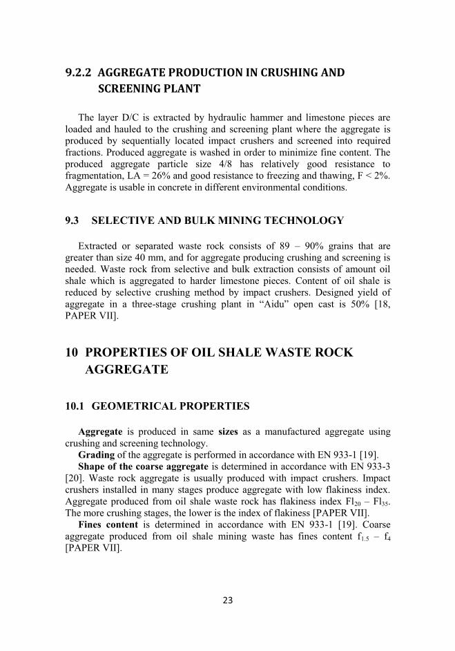
Resistance to fragmentation depends on number of crushing stages (Figure
5). Resistance to fragmentation of oversized aggregate is higher after every stage of crushing. Undersized softer fine aggregate is screened out after every crushing stage.
Figure 5 Resistance to fragmentation depending on number of crushing stages
25
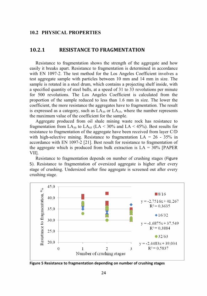
Low resistance to fragmentation is caused by fine and weak oil shale
particles in aggregate. The compressive strength for oil shale is 20 MPa to 40 MPa compared to 40 MPa to 80 MPa for limestone. Resistance to fragmentation of aggregate depends on compressive strength of rock. Tests show that although content of oil shale in waste rock aggregate is decreasing and weak particles are screened out after every stage of crushing and screening, correlation between particle size and resistance to fragmentation is low (Figure 6) [PAPER VI].
Figure 6 Resistance to fragmentation depending on particle size
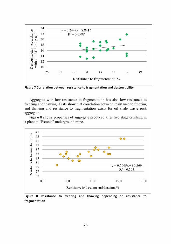
Different methods are used to characterise aggregate resistance to abrasion.
[22, 23]. Previous studies on waste rock have analysed destructibility in accordance with GOST 8269 p 8. Correlation between resistance to fragmentation and destructibility is very low (Figure 7) [PAPER VI].
26
Figure 7 Correlation between resistance to fragmentation and destructibility
Aggregate with low resistance to fragmentation has also low resistance to
freezing and thawing. Tests show that correlation between resistance to freezing and thawing and resistance to fragmentation exists for oil shale waste rock aggregate.
Figure 8 shows properties of aggregate produced after two stage crushing in a plant at “Estonia” underground mine.
Figure 8 Resistance to freezing and thawing depending on resistance to
fragmentation
27
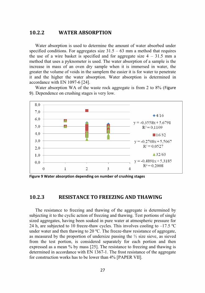
10.2.2 WATER ABSORPTION
Water absorption is used to determine the amount of water absorbed under
specified conditions. For aggregates size 31.5 – 63 mm a method that requires the use of a wire basket is specified and for aggregate size 4 – 31.5 mm a method that uses a pyknometer is used. The water absorption of a sample is the increase in mass of an oven dry sample when it is immersed in water, the greater the volume of voids in the samplem the easier it is for water to penetrate it and the higher the water absorption. Water absorption is determined in accordance with EN 1097-6 [24].
Water absorption WA of the waste rock aggregate is from 2 to 8% (Figure
9). Dependence on crushing stages is very low.
Figure 9 Water absorption depending on number of crushing stages
10.2.3 RESISTANCE TO FREEZING AND THAWING
The resistance to freezing and thawing of the aggregate is determined by
subjecting it to the cyclic action of freezing and thawing. Test portions of single sized aggregates, having been soaked in pure water at atmospheric pressure for 24 h, are subjected to 10 freeze-thaw cycles. This involves cooling to –17.5 ºC under water and then thawing to 20 ºC. The freeze-thaw resistance of aggregate, as measured by the proportion of undersize passing the ½ size sieve, as sieved from the test portion, is considered separately for each portion and then expressed as a mean % by mass [25]. The resistance to freezing and thawing is determined in accordance with EN 1367-1. The frost resistance of the aggregate for construction works has to be lower than 4% [PAPER VII].
28
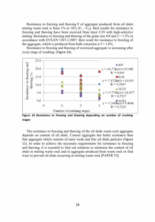
Resistance to freezing and thawing F of aggregate produced from oil shale mining waste rock is from 1% to 18% (F1 - F18). Best results for resistance to freezing and thawing have been received from layer C/D with high-selective mining. Resistance to freezing and thawing of the grain size 4/8 mm f = 1.5% in accordance with EVS-EN 1367-1:2007. Best result for resistance to freezing of the aggregate, which is produced from bulk extraction is f = 1.6%.
Resistance to freezing and thawing of oversized aggregate is increasing after every stage of crushing. (Figure 10).
Figure 10 Resistance to freezing and thawing depending on number of crushing
stages
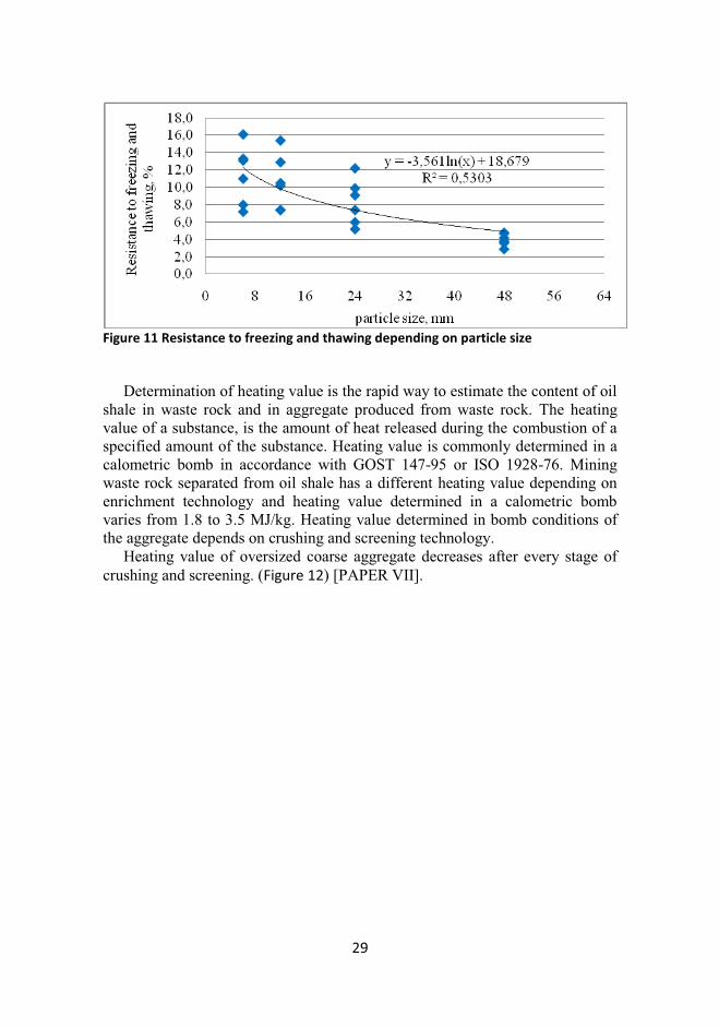
The resistance to freezing and thawing of the oil shale waste rock aggregate
depends on content of oil shale. Coarser aggregate has better resistance than fine aggregate which consists of more weak and fine oil shale particles (Figure
11). In order to achieve the necessary requirements for resistance to freezing and thawing, it is essential to find out solutions to minimize the content of oil shale in mining waste rock and in aggregate produced from waste rock or find ways to prevent oil shale occurring in mining waste rock [PAPER VI].
29
Figure 11 Resistance to freezing and thawing depending on particle size
Determination of heating value is the rapid way to estimate the content of oil
shale in waste rock and in aggregate produced from waste rock. The heating value of a substance, is the amount of heat released during the combustion of a specified amount of the substance. Heating value is commonly determined in a calometric bomb in accordance with GOST 147-95 or ISO 1928-76. Mining waste rock separated from oil shale has a different heating value depending on enrichment technology and heating value determined in a calometric bomb varies from 1.8 to 3.5 MJ/kg. Heating value determined in bomb conditions of the aggregate depends on crushing and screening technology.
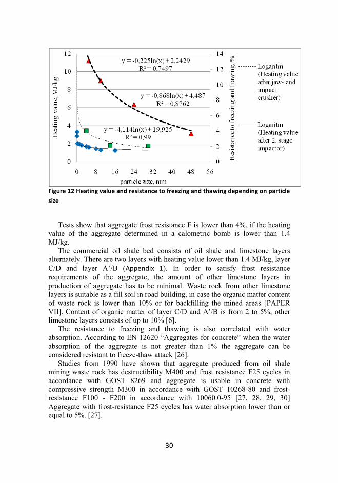
Heating value of oversized coarse aggregate decreases after every stage of crushing and screening. (Figure 12) [PAPER VII].
30
Figure 12 Heating value and resistance to freezing and thawing depending on particle
size
Tests show that aggregate frost resistance F is lower than 4%, if the heating
value of the aggregate determined in a calometric bomb is lower than 1.4 MJ/kg.
The commercial oil shale bed consists of oil shale and limestone layers alternately. There are two layers with heating value lower than 1.4 MJ/kg, layer C/D and layer A’/B (Appendix 1). In order to satisfy frost resistance requirements of the aggregate, the amount of other limestone layers in production of aggregate has to be minimal. Waste rock from other limestone layers is suitable as a fill soil in road building, in case the organic matter content of waste rock is lower than 10% or for backfilling the mined areas [PAPER VII]. Content of organic matter of layer C/D and A’/B is from 2 to 5%, other limestone layers consists of up to 10% [6].
The resistance to freezing and thawing is also correlated with water absorption. According to EN 12620 “Aggregates for concrete” when the water absorption of the aggregate is not greater than 1% the aggregate can be considered resistant to freeze-thaw attack [26].
Studies from 1990 have shown that aggregate produced from oil shale mining waste rock has destructibility M400 and frost resistance F25 cycles in accordance with GOST 8269 and aggregate is usable in concrete with compressive strength M300 in accordance with GOST 10268-80 and frost-resistance F100 - F200 in accordance with 10060.0-95 [27, 28, 29, 30] Aggregate with frost-resistance F25 cycles has water absorption lower than or equal to 5%. [27].
31
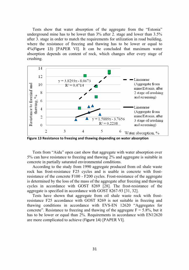
Tests show that water absorption of the aggregate from the “Estonia” underground mine has to be lower than 3% after 2. stage and lower than 3.5% after 3. stage in order to match the requirements for utilization in road building, where the resistance of freezing and thawing has to be lower or equal to 4%(Figure 13) [PAPER VI]. It can be concluded that maximum water absorption depends on content of rock, which changes after every stage of crushing.
Figure 13 Resistance to freezing and thawing depending on water absorption
Tests from “Aidu” open cast show that aggregate with water absorption over
5% can have resistance to freezing and thawing 2% and aggregate is suitable in concrete in partially saturated environmental conditions.
According to the study from 1990 aggregate produced from oil shale waste rock has frost-resistance F25 cycles and is usable in concrete with frost-resistance of the concrete F100 - F200 cycles. Frost-resistance of the aggregate is determined by the loss of the mass of the aggregate after freezing and thawing cycles in accordance with GOST 8269 [28]. The frost-resistance of the aggregate is specified in accordance with GOST 8267-93 [31, 32].
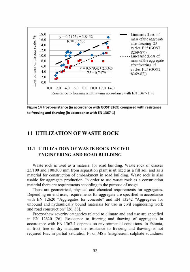
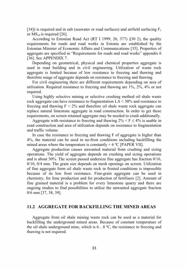
Tests have shown that aggregate from oil shale waste rock with frost-resistance F25 accordance with GOST 8269 is not suitable in freezing and thawing conditions in accordance with EVS-EN 12620 “Aggregates for concrete”. Resistance to freezing and thawing of the aggregate F = 5.8%, but it has to be lower or equal than 2%. Requirements in accordance with EN12620 are more complicated to achieve (Figure 14) [PAPER VI].
32
Figure 14 Frost-resistance (in accordance with GOST 8269) compared with resistance
to freezing and thawing (in accordance with EN 1367-1)
11 UTILIZATION OF WASTE ROCK
11.1 UTILIZATION OF WASTE ROCK IN CIVIL
ENGINEERING AND ROAD BUILDING
Waste rock is used as a material for road building. Waste rock of classes 25/100 and 100/300 mm from separation plant is utilized as a fill soil and as a material for construction of embankment in road building. Waste rock is also usable for aggregate production. In order to use waste rock as a construction material there are requirements according to the purpose of usage.
There are geometrical, physical and chemical requirements for aggregates. Depending on end uses, requirements for aggregate are specified in accordance with EN 12620 “Aggregates for concrete” and EN 13242 “Aggregates for unbound and hydraulically bound materials for use in civil engineering work and road construction” [26, 33].
Freeze-thaw severity categories related to climate and end use are specified in EN 12620 [26]. Resistance to freezing and thawing of aggregates in accordance with EN 1367-1 depends on environmental conditions. In Estonia, in frost free or dry situation the resistance to freezing and thawing is not required FNR, in partial saturation F2 or MS25 (magnesium sulphate soundness
33
[34]) is required and in salt (seawater or road surfaces) and airfield surfacing F1 or MS18 is required [26].
According to Estonian Road Act (RT I 1999, 26, 377) §30 2), the quality requirements for roads and road works in Estonia are established by the Estonian Minister of Economic Affairs and Communications [35]. Properties of aggregate are specified in “Requirements for roads and road works” appendix 6 [36]. See APPENDIX 7.
Depending on geometrical, physical and chemical properties aggregate is used in road building and in civil engineering. Utilization of waste rock aggregate is limited because of low resistance to freezing and thawing and therefore usage of aggregate depends on resistance to freezing and thawing.
For civil engineering there are different requirements depending on area of utilization. Required resistance to freezing and thawing are 1%, 2%, 4% or not required.
Using highly selective mining or selective crushing method oil shale waste rock aggregate can have resistance to fragmentation LA < 30% and resistance to freezing and thawing F < 2% and therefore oil shale waste rock aggregate can replace natural limestone aggregate in road construction. In order to get these requirements, on screen retained aggregate may be needed to crush additionally.
Aggregate with resistance to freezing and thawing 2% < F ≤ 4% is usable in road construction and area of utilization depends on resistance to fragmentation and traffic volume.
In case the resistance to freezing and thawing F of aggregate is higher than 4%, the material can be used in no-frost conditions including backfilling the mined areas where the temperature is constantly + 6 ºC [PAPER VII].
Aggregate production causes unwanted material from crushing and sizing operations. The yield of aggregate depends on crushing and sizing operations and is about 50%. The screen passed undersize fine aggregate has fraction 0/16, 0/10, 0/4 mm. The grain size depends on mesh openings on screen. Utilization of fine aggregate form oil shale waste rock in frosted conditions is impossible because of its low frost resistance. Fine-grain aggregate can be used in chemistry, for lime production and for production of fertilisers [2]. Amount of fine grained material is a problem for every limestone quarry and there are ongoing studies to find possibilities to utilize the unwanted aggregate fraction 0/6 mm [37, 38, 39].
11.2 AGGREGATE FOR BACKFILLING THE MINED AREAS
Aggregate from oil shale mining waste rock can be used as a material for
backfilling the underground mined areas. Because of constant temperature of the oil shale underground mine, which is 6…8 ºC, the resistance to freezing and thawing is not required.
34
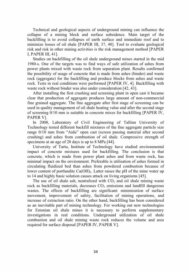
Technical and geological aspects of underground mining can influence the collapse of a mining block and surface subsidence. Main target of the backfilling is to avoid collapses of earth surface and immediate roof and to minimize losses of oil shale [PAPER III, 37, 40]. Tool to evaluate geological risk and risk in other mining activities is the risk management method [PAPER I, PAPER III, 41].
Studies on backfilling of the oil shale underground mines started in the mid 1980-s. One of the targets was to find ways of safe utilization of ashes from power plants mixed with waste rock from separation plant. Results confirmed the possibility of usage of concrete that is made from ashes (binder) and waste rock (aggregate) for the backfilling and produce blocks from ashes and waste rock. Tests in real conditions were performed [PAPER IV, 4]. Backfilling with waste rock without binder was also under consideration [42, 43].
After installing the first crushing and screening plant in open cast it became clear that production of aggregate produces large amount of non-commercial fine grained aggregate. The fine aggregate after first stage of screening can be used in quality management of oil shale heating value and after the second stage of screening 0/10 mm is suitable in concrete mixes for backfilling [PAPER IV, PAPER V].
In 2008, Laboratory of Civil Engineering of Tallinn University of Technology tested different backfill mixtures of the fine aggregate particle size range 0/10 mm from “Aidu” open cast (screen passing material after second crushing) and ashes from combustion of oil shale. Compressive strength of specimens at an age of 28 days is up to 8 MPa [44].
University of Tartu, Institute of Technology have studied environmental impact of concrete mixtures used for backfilling. The conclusion is that concrete, which is made from power plant ashes and from waste rock, has minimal impact on the environment. Preferable is utilisation of ashes formed in circulating fluidized bed than ashes from powdered combustion because of lower content of portlandite Ca(OH)2. Latter raises the pH of the mine water up to 14 and highly basic solution causes attack on living organisms [45].
The use of oil shale ash, neutralized with CO2 and oil shale mining waste rock as backfilling materials, decreases CO2 emissions and landfill dangerous wastes. The effects of backfilling are significant: minimization of surface movement, improvement of safety, facilitation of mining operations, and increase of extraction ratio. On the other hand, backfilling has been considered as an inevitable part of mining technology. For working out new technologies for Estonian oil shale mines it is necessary to perform supplementary investigations in real conditions. Underground utilization of oil shale combustion and oil shale mining waste rock reduces the volume and area required for surface disposal [PAPER IV, PAPER V].
35
12 RESULTS
During crushing and screening process softer particles are screened out and resistance to fragmentation LA and resistance to freezing and thawing F of coarse oversized aggregate improves;
Fine oil shale particles have influence more on resistance to freezing and thawing F and less on resistance to fragmentation LA;
Correlation between resistance to fragmentation LA in accordance with EN and destructibility in accordance with GOST is nonexistent, correlation between resistance to freezing and thawing F accordance with EN and frost-resistance in accordance with GOST exists;
In order to utilise aggregate in civil engineering and in road building the heating value determined in a calometric bomb Qd
b has to be lower than 1.4 MJ/kg; g
The water absorption W depends on content of rock and in order to utilise aggregate in civil engineering and in road building it has to be lower than 2.5…5%;
Areas of waste rock aggregate utilization depends on resistance to freezing and thawing F; other properties e.g. resistance to fragmentation LA, which depends on content of oil shale, have correlation with resistance to freezing and thawing F; freezing
Based on heating value determined in a calometric bomb Qdb, limestone
interlayers A’/B and C/D are usable for civil engineering and road building, other interlayer can be used for backfilling of the mined areas;
Based on heating value determined in a calometric bomb Qdb, waste
rock from separation should be screened in classes over and under 125 mm, oversized waste rock has heating value determined in a calometric bomb Qd
b lower than 1.4 MJ/kg and aggregate produced from it is usable for civil engineering and road building.
13 DISCUSSION
Aggregate can be produced from different types of waste rock. In order to
satisfy requirements of resistance to freezing and thawing of the aggregate for road building, the heating value determined in a calometric bomb must be lower than 1.4 MJ/kg and therefore amount of other layers than C/D and A’/B in production of aggregate must be minimal. It can be achieved using a highly-selective mining or a selective crushing method.
Conclusion that was made on possibilities to apply waste rock aggregate in concrete in accordance with GOST is not valid in accordance with EN requirements and study on waste rock aggregate behaviour in concrete is needed.
36
A rapid way to estimate aggregates resistance to freezing and thawing is a determination of heating value of the (undersized) aggregate.
The produced material from separation plant can be divided in to 3 groups: a. Trade oil shale with net heating value Qr
i ≥ 8.4 MJ/kg; b. Aggregate for civil engineering and road building with heating value
determined in a calometric bomb Qdb ≤ 1.4 MJ/kg;
c. Oil shale waste rock and aggregate with heating value determined in a calometric bomb Qd
b > 1.4 MJ/kg and lower than net heating value Qri < 8.4
MJ/kg which is suitable for backfilling the mined areas.
14 CONCLUSIONS AND RECOMMENDATIONS
Aggregates resistance to freezing and thawing determines the utilization areas of waste rock. Tests affirm that a selective crushing method is the best solution to remove oil shale from waste rock aggregate. Based on heating value, interlayers A’/B and C/D are usable for civil engineering and road building, other interlayers can be used for backfilling of the already mined areas. Oil shale waste rock and produced aggregate from waste rock is suitable in road building and civil engineering in certain conditions.
Utilisation of waste rock helps us to liberate already deposited land areas, to exploit natural resources in more rational ways, to improve public opinion and to reduce the deposited waste in the environment.
37
REFERENCES
[1] Regulation of the Estonian Government, 2005. The rates of the mineral resources extraction charge for the extraction of mineral resources belonging to the state for 2006-2009 (RTI, 71, 553) [in Estonian].
[2] Environmental Charges Act (RT1 I 2005, 67, 512), 2005 [in Estonian].
[3] Adamson, A., 1990. Study on crushing processes of oil shale mining waste rock. Determination of utilization area of the produced aggregate for construction works and data processing for terms of reference of crushing and screening plant. The research report. Contract no 48/89 [in Russian].
[4] Yurkevich, G., 1995. Researching of industrial wastes, composition and industrial testing of building mixtures recipes for the underground mining. Research report. Study no 508L [in Russian].
[5] Hints, O.; Nõlvak, J.; Viira V., 2007. Age of Estonian kukersite oil shale – middle or late Ordovician? Oil Shale, 24(4), 527 – 533.
[6] Kattai, V.; Saadre, T.; Savitski, L., 2000. Estonian Oil Shale: Geology, Resource and Mining Conditions. – Tallinn: Eesti Geoloogiakeskus, 248 pp. [in Estonian with English summary].
[7] Väli, E.; Valgma, I.; Reinsalu E., 2008. Usage of Estonian Oil Shale. Oil Shale, 25(2), 101-114.
[8] Collins, R.J.; Miller, R.H., 1979. Utilization of Mining and Mineral Processing Wastes in the U.S. Minerals and the Environment, v.1, no.1, April 1979, 8-19, (Ref 66).
[9] Adamson, A., 1989. Study on utilization possibilities of the aggregate produced from oil shale mining waste products. Research report no 955. [in Estonian].
[10] GOST 147-95. Solid mineral fuel. Determination of the highest combustion heat and calculation of the lowest combustion heat [in Russian].
[11] Eloranta, J., 2006. Crushing and screening handbook. Metso Minerals. Brochure No. 2051-09-06-CSR/Tampere-English.
[12] Keto, P., Kuula-Väisänen, P., Ruuskanen, J., 2006. Effect of Material Parameters on the Compactibility of Backfill Materials. Workreport 2006-34.
[13] Pennsylvania Crusher, 2003. Handbook of crushing. Bulletin 4050-D. [14] Šommet, J.; Sabanov, S.; Pastarus, J.-R. 2010. Analyses of crushed
limestone quality developed by different methods for conditions of sustainable mining. Проблемы Недропользования. Санкт-Петербургский Государственный Горный Инс, 189, 133 - 135.
38
[15] Nikitin, O.; Väli, E. ;Sabanov, S.; Pastarus, J.-R., 2007. The surface miner sustainable technology introduction for oil-shale mining in Estonia. In: Environment. Technology. Resources: 6th International Scientific and Practical Conference, Rezekne, Latvia, 20-22 June, 2007. (Eds.)Noviks, G.; Morozov, V.; Tepfers, R.; Leal, W.; Chrzan, T.. Rezekne, Latvia: RA Izdevnieciba, 2007, 55 - 61.
[16] Adamson, A., Jostov, M., Kattel, T. 2006. Perspectives for the Mining of Oil Shale and Limestone with Surface Miner in Estonia. Proc. ISCSM Aachen 2006.
[17] Pastarus, J.-R., Adamson, A., Sabanov, S., Väli, E., Nikitin O. 2008. Wirtgen 2500 SM and aggregate production in open pits [in Estonian].
[18] Oljunin, V. V., 1988. Processing of non-metallic construction materials. Moscow. Nedra [in Russian].
[19] EVS-EN 933-1. Tests for geometrical properties of aggregates - Part 1: Determination of particle size distribution – Sieving method.
[20] EVS EN 933-3. Tests for geometrical properties of aggregates - Part 3: Determination of particle shape – Flakiness index.
[21] EVS-EN 1097-2:1998+A1:2006. Tests for mechanical and physical properties of aggregates – Part 2: Methods for the determination of the resistance to fragmentation.
[22] Cuelho, E., Mokwa, R., Obert K., 2007. Comparative analysis of coarse surfacing aggregate using micro-deval, L.A: abrasion and sodium sulphate soundness tests. Report No. FHWA/MT-06-016/8117-27.
[23] Wu, Y., Parker, F., Kandhal, K., 1998. Aggregate toughness/abrasion resistance and durability/ soundness tests related to asphalt concrete performance in pavements. NCAT Report no. 98-4.
[24] EVS-EN 1097-6:2000+AC:2002+A1:2005. Tests for mechanical and physical properties of aggregates – Part 6: Determination of particle density and water absorption.
[25] EVS-EN 1367-1:2007. Tests for thermal and weathering properties of aggregates – Part 1: Determination of resistance to freezing and thawing.
[26] EVS-EN 12620:2002+AC:2004 Aggregates for concrete. [27] Adamson, A., 1990. Determination of utilization possibilities of
aggregates produced from oil shale mining waste rock in civil engineering and determination of producing technology’s rational characteristics. Research report no 042/2 [in Estonian].
[28] GOST 8269-87. Crushed aggregate of natural rock, crushed-gravel aggregate and gravel for construction work. Testing methods [in Russian].
[29] GOST10268-80 Aggregate for heavyweight concrete. Technical requirements [in Russian].
39
[30] GOST 10060.0-95. Concretes. Methods for the determination of frost-resistance. General requirements [in Russian].
[31] GOST 8267-93. Crushed stone and gravel of solid rocks for construction works. Specifications [in Russian].
[32] Adamson, A., 1989. Research and development of recommendations on utilization of aggregate produced from oil shale mining waste rock for construction works. Research report. Contract no 7/88 [in Russian].
[33] EVS-EN 13242:2002+A1:2007 Aggregates for unbound and hydraulically bound materials for use in civil engineering work and road construction.
[34] EVS-EN 1367-2:2009. Tests for thermal and weathering properties of aggregates - Part 2: Magnesium sulfate test.
[35] Estonian Parliament, 199. Road Act (RTI 1999, 26, 377) [in Estonian].
[36] Minister of Economic Affairs and Communications, 2010. “Requirements for roads and road works” [in Estonian].
[37] Naik, T., Kraus, R., Chun, Y., Canpolat, F., Ramme, B., 2005 Use of fly ash and limestone quarry by-products for developing economical self-compacting concrete. Report no CBU-2005-19.
[38] Petavratzi, E., Wilson, S., Sustainable utilisation of quarry by-products. Theme 2 – Sustainable provision of aggregates.
[39] Ramboll Eesti AS. 2009. Tests in situ of washed limestone sand. The Final research report [in Estonian].
[40] Pastarus, J-R., 2009. Waste rock from oil shale mining and separation for backfilling mined areas – Test methods development. Research report. Contract no 9090 [in Estonian].
[41] Pastarus, J.-R., Sabanov, S. Concept of risk assessment for Estonian oil shale mines. Proc. of the 5nd International Conference "Environment. Technology. Resources." (Noviks, G. ed.). Rezekne Augstskolas Izdevnieciba, Rezekne, Latvia, June 16-18, 2005, p.237 -242.
[42] Reinsalu, E., 1993. Technology for producing the construction bricks from oil shale wastes. Research report. Study no 307 [in Russian].
[43] Adamson, A., 1990. Study on possibilities to reduce the rock pressure by backfilling the underground mined area with oil shale mining waste rock. Research report. AM-8017/2 [in Russian].
[44] Raado, L.-M., 2008. Waste rock from oil shale mining and separation for backfilling mined areas. Tallinn University of Technology Department of Building Production Research and Testing Laboratory of Building Materials. Research report. Contract no 8008 [in Estonian].
40
[45] Puura, E., 2008. Utilization of oil shale mining and separation waste for backfilling the mined areas. Environmental impact assessment [in Estonian].
[46] Estonian Energy Mining Co. Mine layout of Estonian oil shale deposit (unpublished manuscript), 2009 [in Estonian].
[47] Soosalu, H.; Valgma, I. (2009). Detection of mine collapses with seismic methods- a case study from Estonia. Valgma, I. (Toim.). Resource Reproducing, Low-wasted and Environmentally Protecting Technologies of Development of the Earth Interior (1 pp.). Tallinn: Department of Mining TUT; Russian University of People Friendship.
[48] Adamson, A., Hints, H., 1989. Possibilities to produce aggregate from oil shale mining waste rock. Proceedings of Tallinn University of Technology. No 695, 16-26 [in Russian].
[49] EE 48008666 TS 026:92. 1992. Estonian Oil Shale Company’s standard. Limestone from rocks accompanying oil shale mining. Specifications [in Estonian].
[50] EVS 1997:2-2003. Geotechnical design - Part 2: Laboratory tests [in Estonian].
[51] GOST 25584-90 Soils. Laboratory methods for determination of filtration factor [in Russian].
[52] EVS-EN 932-3:2000. Tests for general properties of aggregates - Part 3: Procedure and terminology for simplified petrographic description.
[53] EVS-EN 1367-6 Tests for thermal and weathering properties of aggregates - Part 6: Determination of resistance to freezing and thawing in the presence of salt (NaCl).
[54] EE 48008666 TS 030:92, 1992. Estonian Oil Shale Company’s standard. Limestone chips from rock accompanying oil shale mining. Specifications [in Estonian].
41
LIST OF AUTHOR’S PUBLICATIONS Tohver, T., 2010. Utilization of waste rock from oil shale mining. Oil Shale,
2010, Vol. 27 (4), pp. 321–330. Tohver, T., 2010. Oil shale waste rock aggregate properties which are
depending on content of oil shale. In: 9th International Symposium "Topical Problems in the Field of Electrical and Power Engineering". Pärnu, Estonia, 14.06.-19.06.2010. (Toim.) Lahtmets, R.. Estonian Society of Moritz Hermann Jacobi, 2010, 59 - 62.
Tohver, T., 2010. Fine aggregates produced from oil shale mining waste rock for backfilling the mined areas. Проблемы Недропользования. Санкт-Петербургский Государственный Горный Инс, 189, 104 - 106.
Pastarus, J.-R.; Tohver, T.; Väli, E., 2009. Backfilling and waste management in Estonian oil shale industry. In: Future energy solutions: International Oil Shale Symposium, Tallinn, Estonia, June 8-11, 2009. (Toim.) Sirli Peda. Tallinn, Estonia: Tallinn, EE, 2009, 48 - 49.
Tohver, T., 2009. MTÜ Eesti Mäeselts tegevus 2008 aastal. Valgma, I.; Õnnis, A.; Reinsalu, E.; Sõstra, Ü.; Uibopuu, L.; Västrik, A.; Robam, K.; Vesiloo, P.; T (Toim.). Mäenduse maine (155 - 156).Tallinna Tehnikaülikooli Kirjastus.
Sabanov, S.; Tohver, T.; Väli, E.; Nikitin, O.; Pastarus, J.-R., 2008. Geological aspects of risk management in oil shale mining. Oil Shale, 25(2S), 145 - 152.
Lohk, M.; Väli, E.; Tohver, T.; Pastarus, J.-R., 2008. Surface miner technology impact on the environment . In: 5th International Symposium "Topical problems in the field of electrical and power engineering". Doctoral school of energy and geotechnology: (Toim.) Lahtmets, R.. Tallinna Tehnikaülikool, 44 - 47.
Tuuna, V.; Tohver, T., 2008. MTÜ Eesti Mäeseltsi tegemisi ja tulevikuplaane. Valgma, I. (Toim.). Killustiku kaevandamine ja kasutamine (82 - 84).Tallinna Tehnikaülikooli mäeinstituut.
Pastarus, J-R.; Sabanov, S.; Tohver, T., 2007. Application of the risk assessment methods of railway transport in Estonian oil shale industry. Oil Shale, 24(1), 35 - 44.
Tammeoja, T.; Loko, M.; Valgma, I.; Karu, V.; Tohver, T., 2007. Oil shale reserves in Estonia. In: 4th International Symposium "Topical Problems in the Field of Electrical and Power Engineering" : Doctoral School of Energy and Geotechnology: 4th International Symposium "Topical Problems in the Field of Electrical and Power Engineering", Kuressaare, Estonia, 15.-20.01.2007. (Toim.) Lahtmets, R.. Tallinn: Tallinn University of Technology Faculty of Power Engineering, 2007, 94 - 95.
42
Pastarus, J.-R.; Erg, K.; Nikitin, O.; Sabanov, S.; Väli, E.; Tohver, T., 2007. Geological aspects of risk management in oil shale mining. In: Georesources and public policy: research, management, environment. 15th Meeting of the Association of European Geological Societies. 16-20 September 2007, Tallinn, Estonia : abstracts: 15th Meeting of the Association of European Geological Societies, Tallinn (Estonia), 16-20 September 2007. (Toim.) Hints, O.; Kaljo, D.. Tallinn: Eesti Geoloogia Selts, 2007, 47 - 48.
Liias, M.; Grossfeldt, G.; Noška, M.; Zaikin, I.; Šestakova, J.; Tohver, T.; Anepaio, A.; Baljasnikova, T.; Sabanov, S., 2007. Kaevandamise mõju Maardu fosforiidilevilas [välitöö aruanne]. Kaevandamine parandab maad (17 lk.). Tallinn: Tallinna Tehnikaülikooli Kirjastus.
Kaljuste, M.; Ring, M.; Robam, K.; Saum, M.; Sein, O.; Tohver, T. ; Väizene, V.; Õnnis, A.-Õ., 2007. Liiva ladustamismahtude hindamine talviseks perioodiks Männiku karjääris [välitöö aruanne]. Kaevandamine parandab maad (18 lk.). Tallinn: Tallinna Tehnikaülikooli Kirjastus.
Tohver, T., 2006. Mehaanikatehase osa põlevkivi kaevandamisel. 90 aastat põlevkivi kaevandamist Eestis : Eesti mäekonverents : [5. mai] 2006, [Jõhvi / Eesti Mäeselts] (98 - 99). Tallinn: Tallinna Tehnikaülikool.
Valgma, I.; Reinsalu, E.; Erg, K.; Kattel, T.; Lind, H.; Mets, M.; Pastarus, J.-R.; Sõstra, Ü.; Sabanov, S.; Rannik, E.; Karu, V.; Västrik, A.; Tohver, T.; Hansen, R.; Tammemäe, O.; Torn, H., 2006. Eesti maapõue geotehnoloogilised mudelid, erijuhus - lavamaardlad.
43
KOKKUVÕTE
Eesti tähtsaima maavara kukersiidi kaevandamise, rikastamise ja täitematerjalide tootmise käigus saadavad jäägid on kasutatavad erinevatel eesmärkidel. Põlevkivi tööstuslik kihind sisaldab lisaks põlevkivi kihtidele ka paekihte ja suletisi, mille survetugevus on 40 – 80 MPa samal ajal, kui põlevkivi survetugevus on 24 – 40 MPa.
Varasemad uuringud on 90-ndatel on näidanud, et aherainest toodetud täitematerjal margiga M400 - M600 ning külmakindlusega 25 tsüklit on kasutatav väikese koormusega teedel ning tagab betooni tugevuse M300 ja külmakindluse F150 – F200 vastavalt GOST. Leitud on kriitiline veeimavus 5%, mille juures täitematerjali saab ehituses kasutada. Uuringud kinnitasid ka sõelaaluse peene täitematerjali kasutamise võimalikkust kaevanduste tagasitäite betoonides, mille sideaine komponendiks oli põlevkivi küttel töötava elektrijaama tolmkihtkatelde tuhk. Uuringute käigus selgus, et parimaks kasutatavaks tehnoloogiaks on mitmeastmeline valikpurustamine ning parimaks purusti tüübiks rootorpurusti. Katsetati ka killustiku tootmist lõugpurustitega. 2001. a purustati Estonia kaevanduse ja Aidu karjääri aherainet kaheastmelises rootorpurustitega sõlmes ning saavutati purunemiskindlus LA ≤ 35% ja külmakindlus F = 4 - 14%. Järeldati, et täitematerjali parema külmakindluse saamiseks, on vajalik täiendavalt purustada sõelapealne +20 mm materjal. 2006. a paigaldati Aidu karjääri 3-astmeline rootorpurustitega purustussõlm, mis tagab täitematerjali purunemiskindluse LA ≤ 35% ja külmakindluse F ≤ 4%.
Täitematerjalide omaduste peamiseks probleemiks on madal külma- ja purunemiskindlus, mis on tingitud nõrkade põlevkivi terade sisaldusest täitematerjalis. Vajalik on leida lahendus põlevkivi osakeste eemaldamiseks lubjakivist või vältida põlevkivi sattumist täitematerjalide hulka.
Metoodikana on kasutatud aherainest erinevate tehnoloogiatega toodetud täitematerjalide katsetulemusi ning tehtud statistiline analüüs ning leitud seaduspärasused.
Käesoleva töö tulemusena on leitud, et täitematerjali külmakindlus määrab ära aheraine kasutamise võimaluse. Katsed kinnitavad, põlevkivi sisaldusest sõltuvad muud omadused on korrelatsioonis külmakindlusega. Purustustsüklite arvu suurendades purustatakse nõrgem põlevkivi sisaldav materjal ning sõelapealse materjali külma- ja purunemiskindlus paraneb. Põlevkivi osakesed mõjutavad täitematerjali külmakindlust ja vähem purunemiskindlust. Killustiku tugevusomaduste võrdlemisel GOST ja EN vahel on leitud, et puudub sõltuvus purunemiskindluse ja silindris purunemise vahel, leitud on sõltuvus külmakindluste vahel. On leitud kriitiline kütteväärtuse piir Qb
d < 1.4 MJ/kg, mille juures on täitematerjal kasutatav ehitustegevuses vastavalt EN nõuetele. On leitud, et kriitiline veeimavus, mille juures on täitematerjal kasutatav ehitustegevuses sõltub kivimi koostisest ning on vahemikus 2.5 – 5%. Lähtudes

44
kütteväärtusest on ehitustegevuses kasutatavad kihid A/B ja C/D, ülejäänud kihid ehitustegevuseks ei sobi ning on teoreetiliselt sobilikud kasutamiseks tagasitäitmisel. GOST põhjal saadud järeldused täitematerjali kasutamiseks betoonis ei kehti EN nõuete puhul ning vajadus on teostada uued uuringud. Kuna külmakindlus on sõltuvuses kütteväärtusest võib külmakindluse kiirmääramiseks kasutada täitematerjali (sõelmete) kütteväärtust.
Teades aheraine täitematerjali omadusi ning rakendades valikpurustamist ning kõrgselektiivset väljamist, on võimalik senisest enam kasutada aherainet.
45
ABSTRACT
Estonian most important mineral resource is a specific kind of oil shale – kukersite. The waste rock extracted in mining or separated in plant is usable for different purposes. In addition to oil shale, the commercial bed of oil shale consists of limestone layers and concretions with compressive strength from 40 to 80 MPa. The compressive strength of oil shale is 24 – 40 MPa.
Studies from 90-s have shown that aggregate produced from oil shale mining waste rock with destructibility M400-M600 and frost resistance 25 cycles can be used in road building with low traffic volume and to guarantee a compressive strength of concrete M300 and frost resistance F150-F200 in accordance with GOST. In order to utilize aggregate in road building and civil engineering, the maximum limit of water absorption 5% was determined. Also, conclusion was made that undersized fine aggregate is usable for backfilling of the mined areas in concretes, where ashes from powdered combustion are used as a binder. Different schemes of crushing and screening showed that the best type of crusher is impact crusher because it uses selective crushing, a method that liberates weak oil shale particles from hard limestone waste rock.
In 2001/02, aggregate from waste rock from “Estonia” underground mine and “Aidu” open cast was produced with a two-stage crushing plant with impact crushers. Tests show that aggregates resistance to fragmentation LA is lower than 35% and resistance to freezing and thawing F is 4 … 14%. The conclusion was made that in order to increase the quality of coarse aggregate, a third impact crusher shall be installed to crush additionally oversized 20 mm aggregate. In 2006, a three-stage crushing plant with impact crushers was installed in “Aidu” open cast. The production scheme guarantees aggregates resistance to fragmentation LA ≤ 35% and resistance to freezing and thawing F ≤ 4%.
The main problem of the properties of aggregate is low resistance to fragmentation and resistance to freezing and thawing, which is caused by fine and weak oil shale particles. It is essential to find ways to extract oil shale and limestone separately.
This study shows that resistance to freezing and thawing determines areas utilization of aggregate. Tests show that properties, which depend on content on oil shale, are correlated with resistance to freezing and thawing. Resistance to freezing and thawing of oversized coarse aggregate increases after every stage of crushing because weaker and finer aggregate is screened out. Particles of oil shale have greater impact on resistance to freezing and thawing than on resistance to fragmentation. There is no correlation between destructibility (in accordance with GOST) and resistance to fragmentation (in accordance with EN). Correlation between frost-resistance (GOST) and resistance to freezing and thawing (EN) exists. The heating value of the aggregate, which is usable for road building and civil engineering Qb
d is lower than 1.4 MJ/kg. Water
46
absorption depends on content of rock and W < 2.5…5%. Based on heating value, the interlayers A/B and C/D are usable in civil engineering and road building. Other interlayers are usable for backfilling of the already mined areas. The conclusion for utilisation of aggregate in concrete, which is made in accordance with GOST is not suitable in EN conditions and there is a need to study aggregate behaviour in concrete in accordance with EN requirements. A rapid way to estimate aggregates resistance to freezing and thawing is to determine the heating value of aggregate.
Knowing properties of aggregate and applying a selective crushing and highly selective mining method, it is possible to utilize more oil shale waste rock.
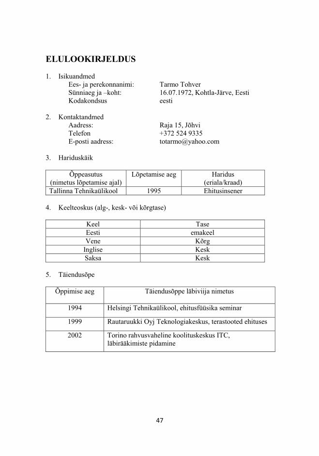
47
ELULOOKIRJELDUS 1. Isikuandmed Ees- ja perekonnanimi: Tarmo Tohver Sünniaeg ja –koht: 16.07.1972, Kohtla-Järve, Eesti Kodakondsus eesti 2. Kontaktandmed Aadress: Raja 15, Jõhvi Telefon +372 524 9335 E-posti aadress: [email protected] 3. Hariduskäik
Õppeasutus
(nimetus lõpetamise ajal) Lõpetamise aeg Haridus
(eriala/kraad) Tallinna Tehnikaülikool 1995 Ehitusinsener
4. Keelteoskus (alg-, kesk- või kõrgtase)
Keel Tase Eesti emakeel Vene Kõrg
Inglise Kesk Saksa Kesk
5. Täiendusõpe
Õppimise aeg Täiendusõppe läbiviija nimetus
1994 Helsingi Tehnikaülikool, ehitusfüüsika seminar
1999 Rautaruukki Oyj Teknologiakeskus, terastooted ehituses
2002 Torino rahvusvaheline koolituskeskus ITC, läbirääkimiste pidamine
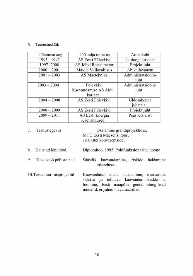
48
6. Teenistuskäik
Töötamise aeg Tööandja nimetus Ametikoht 1995 - 1997 AS Eesti Põlevkivi ökoloogiainsener 1997 -2000 AS Jõhvi Restauraator Projektijuht 2000 – 2001 Maidla Vallavalitsus Abivallavanem 2001 – 2003 AS Mäetehnika Administratsiooni-
juht 2003 – 2004 Põlevkivi
Kaevandamise AS Aidu karjäär
Administratsiooni-juht
2004 – 2008 AS Eesti Põlevkivi Üldosakonna juhataja
2008 – 2009 AS Eesti Põlevkivi Projektijuht 2009 – 2011 AS Eesti Energia
Kaevandused Peaspetsialist
7. Teadustegevus Osalemine grandiprojektides,
MTÜ Eesti Mäeseltsi töös, erialastel konverentsidel.
8. Kaitstud lõputööd. Diplomitöö, 1995, Polüfunktsionaalne hoone
9. Teadustöö põhisuunad Säästlik kaevandamine, riskide haldamine mäenduses
10. Teised uurimisprojektid Kaevandatud alade kasutamine, maavarade
säästva ja talutava kaevandamiskeskkonna loomine, Eesti maapõue geotehnoloogilised mudelid, erijuhus - lavamaardlad
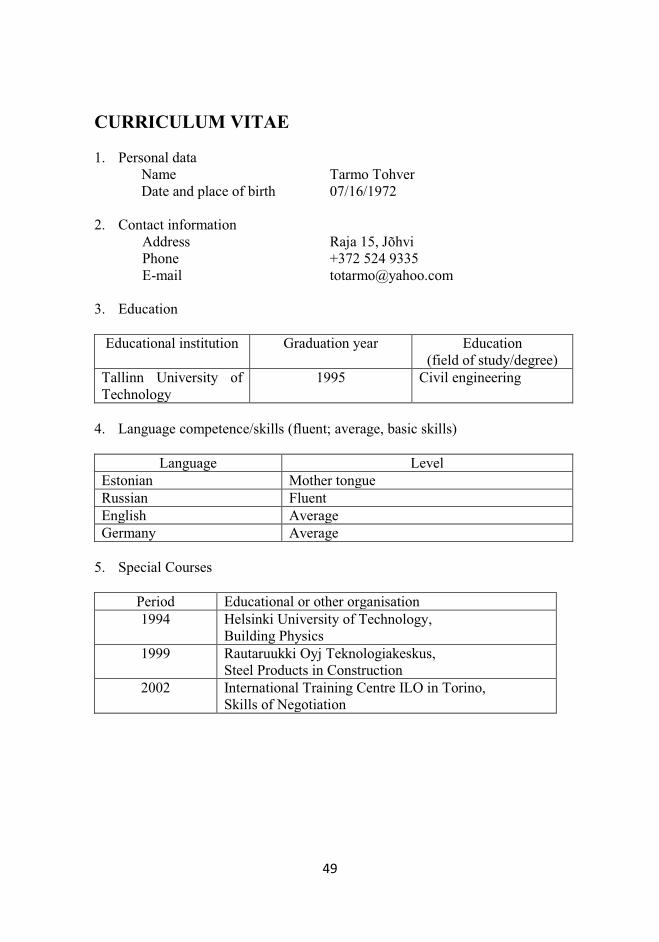
49
CURRICULUM VITAE 1. Personal data
Name Tarmo Tohver Date and place of birth 07/16/1972 2. Contact information Address Raja 15, Jõhvi Phone +372 524 9335 E-mail [email protected] 3. Education
Educational institution Graduation year Education (field of study/degree)
Tallinn University of Technology
1995 Civil engineering
4. Language competence/skills (fluent; average, basic skills)
Language Level Estonian Mother tongue Russian Fluent English Average Germany Average
5. Special Courses
Period Educational or other organisation 1994 Helsinki University of Technology,
Building Physics 1999 Rautaruukki Oyj Teknologiakeskus,
Steel Products in Construction 2002 International Training Centre ILO in Torino,
Skills of Negotiation
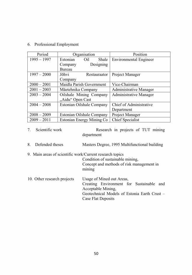
50
6. Professional Employment
Period Organisation Position 1995 – 1997 Estonian Oil Shale
Company Designing Bureau
Environmental Engineer
1997 – 2000 Jõhvi Restauraator Company
Project Manager
2000 – 2001 Maidla Parish Government Vice-Chairman 2001 – 2003 Mäetehnika Company Administrative Manager 2003 – 2004 Oilshale Mining Company
„Aidu“ Open Cast Administrative Manager
2004 – 2008 Estonian Oilshale Company Chief of Administrative Department
2008 – 2009 Estonian Oilshale Company Project Manager 2009 – 2011 Estonian Energy Mining Co Chief Specialist
7. Scientific work Research in projects of TUT mining
department 8. Defended theses Masters Degree, 1995 Multifunctional building 9. Main areas of scientific work/Current research topics
Condition of sustainable mining, Concept and methods of risk management in mining
10. Other research projects Usage of Mined out Areas,
Creating Environment for Sustainable and Acceptable Mining, Geotechnical Models of Estonia Earth Crust – Case Flat Deposits

51
15 Appendixes
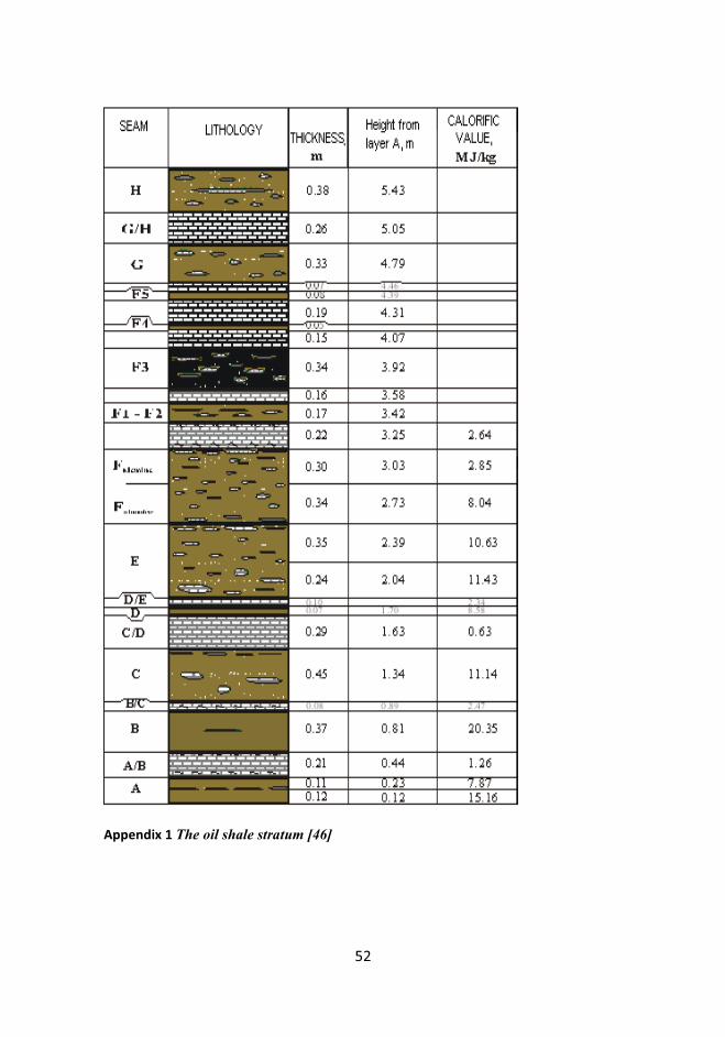
52
Appendix 1 The oil shale stratum [46]
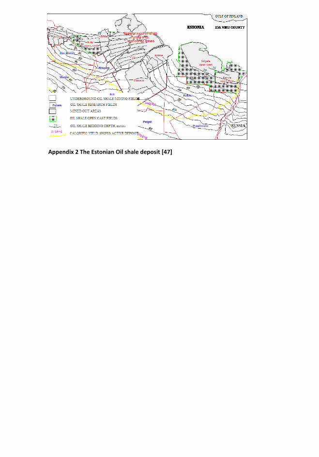
Appendix 2 The Estonian Oil shale deposit [47]
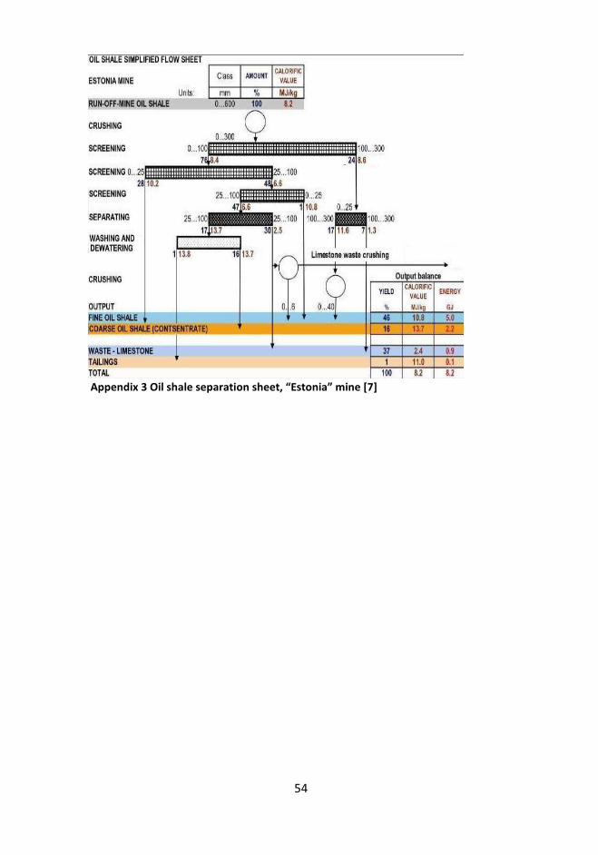
54
Appendix 3 Oil shale separation sheet, “Estonia” mine [7]
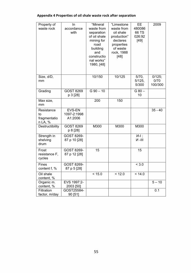
55
Appendix 4 Properties of oil shale waste rock after separation
Property of waste rock
In accordance
with
“Mineral
waste from separation of oil shale mining for
road building
and constructional works” 1980, [48]
“Limestone
waste from oil shale
production” declares
properties of waste
rock, 1988 [48]
EE 48008666 TS 026:92
[49]
2009
Size, d/D, mm
10/150 10/125 5/70, 5/125, 5/300
0/125; 0/70
100/300
Grading GOST 8269 p 3 [28]
G 90 – 10 G 80 – 10
Max size, mm
200 150
Resistance to fragmentation LA, %
EVS-EN 1097-2:1998
A1:2006
35 - 40
Destructibility GOST 8269 p 8 [28]
M300 M300 M300
Strength in shelving drum
GOST 8269-87 p 10 [28]
И-I ; И -III
Frost resistance F, cycles
GOST 8269-87 p 12 [28]
15 15
Fines content f, %
GOST 8269-87 p 5 [28]
< 3.0
Oil shale content, %
< 15.0 < 12.0 < 14.0
Organic m. content, %
EVS 1997:2-2003 [50]
5 – 10
Filtration factor, m/day
GOST25584-90 [51]
0.1
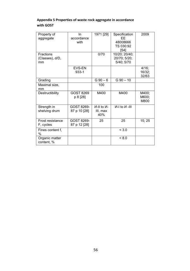
56
Appendix 5 Properties of waste rock aggregate in accordance
with GOST
Property of aggregate
In accordance
with
1971 [29] Specification EE
48008666 TS 030:92
[54]
2009
Fractions (Classes), d/D, mm
0/70 10/20; 20/40; 20/70; 5/20; 5/40; 5/70
EVS-EN 933-1
4/16; 16/32; 32/63
Grading G 90 – 6 G 90 – 10
Maximal size, mm
100
Destructibility GOST 8269 p 8 [28]
M400 M400 M400; M600; M800
Strength in shelving drum
GOST 8269-87 p 10 [28]
И-II to И-III, max
40%
И-I to И -III
Frost resistance F, cycles
GOST 8269-87 p 12 [28]
25 25 15; 25
Fines content f, %
< 3.0
Organic matter content, %
< 8.0
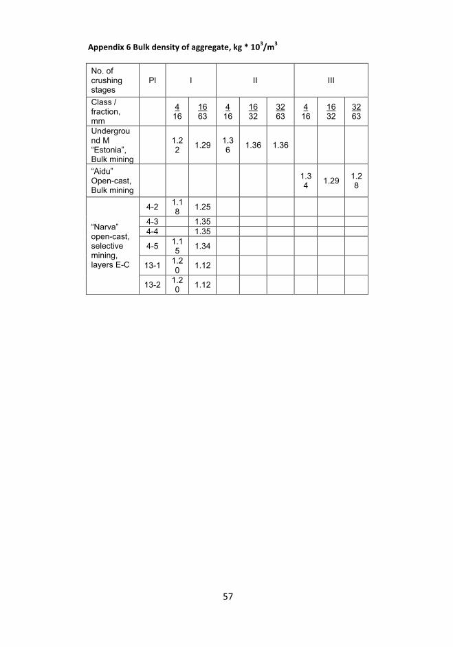
57
Appendix 6 Bulk density of aggregate, kg * 103/m
3
No. of crushing stages
Pl I II III
Class / fraction, mm
4
16 16 63
4 16
16 32
32 63
4 16
16 32
32 63
Underground M “Estonia”, Bulk mining
1.22
1.29 1.36
1.36 1.36
“Aidu”
Open-cast, Bulk mining
1.34
1.29 1.28
“Narva”
open-cast, selective mining, layers E-C
4-2 1.18
1.25
4-3 1.35
4-4 1.35
4-5 1.15
1.34
13-1 1.20
1.12
13-2 1.20
1.12
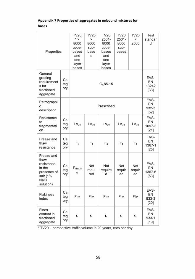
58
Appendix 7 Properties of aggregates in unbound mixtures for
bases
Properties
TV20 * >
8000 upper bases and one layer bases
TV20 >
8000 sub-base
s
TV20 2501-8000 upper bases and one layer bases
TV20 2501-8000 sub-
bases
TV20 <
2500
Test standar
d
General grading requirements for fractioned aggregate
Category
GC85-15
EVS-EN
13242 [33]
Petrographic description
Prescribed
EVS-EN
932-3 [52]
Resistance to fragmentation
Category
LA25 LA30 LA30 LA35 LA35
EVS-EN
1097-2 [21]
Freeze and thaw resistance
Category
F2 F4 F4 F4 F4
EVS-EN
1367-1 [25]
Freeze and thaw resistance in the presence of salt (1% NaCl solution)
Category
FNaCl8
%
Not required
Not require
d
Not requir
ed
Not requir
ed
EVS-EN
1367-6 [53]
Flakiness index
Category
Fl20 Fl20 Fl20 Fl20 Fl35
EVS-EN
933-3 [20]
Fines content in fractioned aggregate
Category
f4 f4 f4 f4 f4
EVS-EN
933-1 [19]
* TV20 – perspective traffic volume in 20 years, cars per day
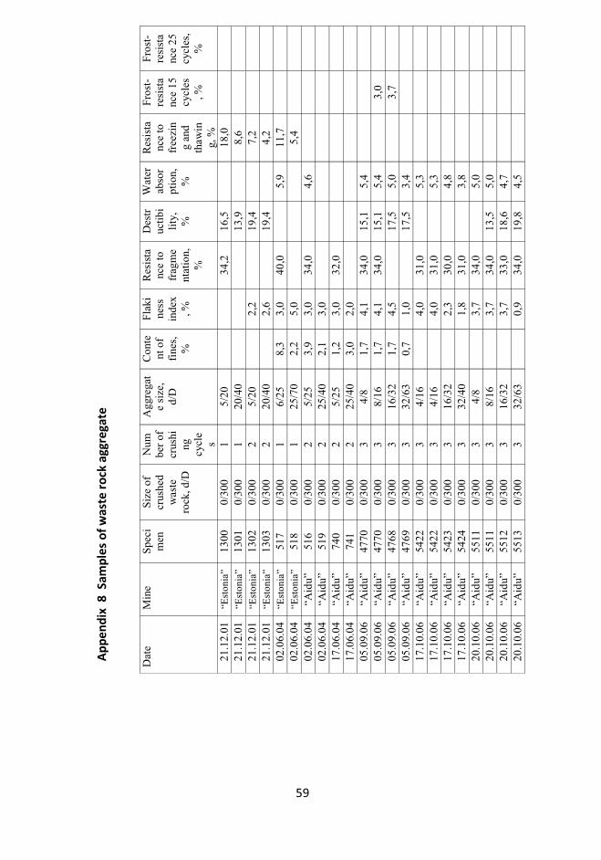
59
Dat
e M
ine
Spe
cim
en
Siz
e of
cr
ushe
d w
aste
ro
ck, d
/D
Num
ber
of
crus
hing
cy
cle
s
Agg
rega
te
size
, d/
D
Con
tent
of
fine
s,
%
Fla
kine
ss
inde
x, %
Res
ista
nce
to
frag
me
ntat
ion,
%
Des
truc
tibi
lity
, %
Wat
er
abso
rpt
ion,
%
Res
ista
nce
to
free
zin
g an
d th
awin
g, %
Fro
st-
resi
sta
nce
15
cycl
es, %
Fro
st-
resi
sta
nce
25
cycl
es,
%
21.1
2.01
“E
ston
ia”
1300
0/
300
1 5/
20
34,2
16
,5
18
,0
21.1
2.01
“E
ston
ia”
1301
0/
300
1 20
/40
13
,9
8,
6
21
.12.
01
“Est
onia
” 13
02
0/30
0 2
5/20
2,2
19
,4
7,
2
21
.12.
01
“Est
onia
” 13
03
0/30
0 2
20/4
0
2,6
19
,4
4,
2
02
.06.
04
“Est
onia
” 51
7 0/
300
1 6/
25
8,3
3,0
40,0
5,9
11,7
02
.06.
04
“Est
onia
” 51
8 0/
300
1 25
/70
2,2
5,0
5,
4
02
.06.
04
“Aid
u”
516
0/30
0 2
5/25
3,
9 3,
0 34
,0
4,
6
02.0
6.04
“A
idu”
51
9 0/
300
2 25
/40
2,1
3,0
17.0
6.04
“A
idu”
74
0 0/
300
2 5/
25
1,2
3,0
32,0
17.0
6.04
“A
idu”
74
1 0/
300
2 25
/40
3,0
2,0
05.0
9.06
“A
idu”
47
70
0/30
0 3
4/8
1,7
4,1
34,0
15
,1
5,4
05
.09.
06
“Aid
u”
4770
0/
300
3 8/
16
1,7
4,1
34,0
15
,1
5,4
3,
0
05.0
9.06
“A
idu”
47
68
0/30
0 3
16/3
2 1,
7 4,
5
17,5
5,
0
3,7
05
.09.
06
“Aid
u”
4769
0/
300
3 32
/63
0,7
1,0
17
,5
3,4
17
.10.
06
“Aid
u”
5422
0/
300
3 4/
16
4,
0 31
,0
5,
3
17.1
0.06
“A
idu”
54
22
0/30
0 3
4/16
4,0
31,0
5,3
17
.10.
06
“Aid
u”
5423
0/
300
3 16
/32
2,
3 30
,0
4,
8
17.1
0.06
“A
idu”
54
24
0/30
0 3
32/4
0
1,8
31,0
3,8
20
.10.
06
“Aid
u”
5511
0/
300
3 4/
8
3,7
34,0
5,0
20
.10.
06
“Aid
u”
5511
0/
300
3 8/
16
3,
7 34
,0
13,5
5,
0
20.1
0.06
“A
idu”
55
12
0/30
0 3
16/3
2
3,7
33,0
18
,6
4,7
20
.10.
06
“Aid
u”
5513
0/
300
3 32
/63
0,
9 34
,0
19,8
4,
5
Ap
pe
nd
ix 8
Sa
mp
les
of
wa
ste
ro
ck a
gg
reg
ate

60
Dat
e M
ine
Spe
cim
en
Siz
e of
cr
ushe
d w
aste
ro
ck, d
/D
Num
ber
of
crus
hing
cy
cle
s
Agg
rega
te
size
, d/
D
Con
tent
of
fine
s,
%
Fla
kine
ss
inde
x, %
Res
ista
nce
to
frag
me
ntat
ion,
%
Des
truc
tibi
lity
, %
Wat
er
abso
rpt
ion,
%
Res
ista
nce
to
free
zin
g an
d th
awin
g, %
Fro
st-
resi
sta
nce
15
cycl
es, %
Fro
st-
resi
sta
nce
25
cycl
es,
%
24.1
1.06
“E
ston
ia”
6181
0/
125
1 0/
125
33,0
17
,8
3,3
6,6
8,1
14,2
24
.11.
06
“Est
onia
” 61
85
125/
300
1 12
5/30
0
33
,0
16,0
2,
8 4,
2 7,
2 11
,3
24.1
1.06
“E
ston
ia”
6182
0/
125
2 0/
125
32,0
16
,5
3,8
3,9
5,8
11,2
24
.11.
06
“Est
onia
” 61
86
125/
300
2 12
5/30
0
31
,0
16,1
3,
3 3,
7 5,
8 10
,0
24.1
1.06
“E
ston
ia”
6179
0/
125
3 4/
16
4,
6 31
,0
13,0
4,
5 4,
8 6,
1 11
,1
24.1
1.06
“E
ston
ia”
6180
12
5/30
0 3
4/16
4,1
30,0
13
,7
4,3
4,6
5,5
10,0
24
.11.
06
“Est
onia
” 61
77
0/12
5 3
16/3
2
2,9
33,0
17
,7
4,9
2,7
3,9
6,3
24.1
1.06
“E
ston
ia”
6178
12
5/30
0 3
16/3
2
3,2
30,0
17
,7
4,3
3,2
4,2
6,6
24.1
1.06
“E
ston
ia”
6184
0/
125
3 32
/40
4,
3 31
,0
15,6
3,
6 1,
4 1,
3 2,
6 24
.11.
06
“Est
onia
” 61
83
125/
300
3 32
/40
1,
5 31
,0
17,0
4,
2 1,
7 1,
5 3,
6 04
.01.
07
“Est
onia
” 26
9 0/
300
1 4/
8
7,8
37,0
14
,8
5,8
19,6
04
.01.
07
“Est
onia
” 26
9 0/
300
1 8/
16
7,
8 37
,0
14,0
5,
8 17
,1
04.0
1.07
“E
ston
ia”
269
0/30
0 1
16/3
2
7,8
37,0
5,8
11,7
04
.01.
07
“Est
onia
” 27
0 0/
300
1 16
/32
4,
4 33
,0
19,0
5,
0 9,
7
04
.01.
07
“Est
onia
” 27
0 0/
300
1 32
/63
4,
4 33
,0
19,0
5,
0 6,
2
04
.01.
07
“Est
onia
” 26
8 0/
300
1 32
/63
4,
7 37
,0
21,8
5,
8 18
,0
02.0
7.07
“V
iru”
28
73
0/30
0 1
8/11
45
,0
02
.07.
07
“Vir
u”
2874
0/
300
1 16
/32
37,0
02.0
7.07
“V
iru”
28
75
0/30
0 1
16/3
2
35
,0
16
.07.
07
“Nar
va”
3078
E
/C
1 4/
16
8,4
16
.07.
07
“Nar
va”
3075
E
/C
1 16
/32
1,3
38
,0
16
.07.
07
“Nar
va”
3074
E
/C
1 32
/63
0,6
35
,0
19
.07.
07
“Vir
u”
3164
0/
300
1 4/
8 2,
4 19
,0
17
,7
20
,1
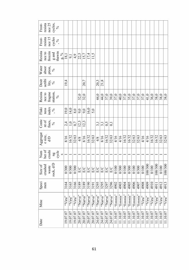
61
Dat
e M
ine
Spe
cim
en
Siz
e of
cr
ushe
d w
aste
ro
ck, d
/D
Num
ber
of
crus
hing
cy
cle
s
Agg
rega
te
size
, d/
D
Con
tent
of
fine
s,
%
Fla
kine
ss
inde
x, %
Res
ista
nce
to
frag
me
ntat
ion,
%
Des
truc
tibi
lity
, %
Wat
er
abso
rpt
ion,
%
Res
ista
nce
to
free
zin
g an
d th
awin
g, %
Fro
st-
resi
sta
nce
15
cycl
es, %
Fro
st-
resi
sta
nce
25
cycl
es,
%
19.0
7.07
“V
iru”
31
64
0/30
0 1
8/16
2,
4 19
,0
19
,4
18
,1
19.0
7.07
“V
iru”
31
65
0/30
0 1
16/3
2 1,
0 14
,0
9,
1
19
.07.
07
“Vir
u”
3166
0/
300
1 32
/63
0,7
8,0
4,
9
20
.07.
07
“Nar
va”
3189
E
/C
1 4/
8 12
,3
9,0
32,0
22
,5
20.0
7.07
“N
arva
” 31
89
E/C
1
8/16
12
,3
9,0
32,0
20
,7
15
,7
20.0
7.07
“N
arva
” 31
90
E/C
1
16/3
2
16,0
17,4
20
.07.
07
“Nar
va”
3191
E
/C
1 32
/63
5,
0
11,5
24
.07.
07
“Nar
va”
3295
E
/C
1 4/
8 3,
1
44,0
20
,3
24.0
7.07
“N
arva
” 32
95
E/C
1
8/16
3,
1
44,0
21
,8
24.0
7.07
“N
arva
” 32
97
E/C
1
16/3
2 0,
5
37,0
24.0
7.07
“N
arva
” 32
96
E/C
1
32/6
3 0,
1
39,0
11.1
0.07
“E
ston
ia”
4902
0/
100
1 4/
16
37,0
11.1
0.07
“E
ston
ia”
4903
0/
300
1 4/
16
40,0
11.1
0.07
“E
ston
ia”
4904
0/
100
1 16
/32
37,0
11.1
0.07
“E
ston
ia”
4905
0/
300
1 16
/32
35,0
11.1
0.07
“E
ston
ia”
4906
0/
100
1 32
/63
37,0
11.1
0.07
“E
ston
ia”
4907
0/
300
1 32
/63
37,0
11.1
0.07
“V
iru”
49
08
0/10
0 1
4/16
37
,0
11
.10.
07
“Vir
u”
4909
10
0/30
0 1
4/16
41
,0
11
.10.
07
“Vir
u”
4910
0/
100
1 16
/32
36,0
11.1
0.07
“V
iru”
49
11
100/
300
1 16
/32
38,0
11.1
0.07
“V
iru”
49
12
0/10
0 1
32/6
3
38
,0
11
.10.
07
“Vir
u”
4913
10
0/30
0 1
32/6
3
38
,0
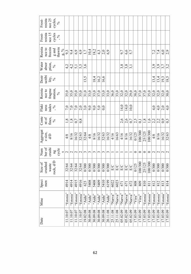
62
Dat
e M
ine
Spe
cim
en
Siz
e of
cr
ushe
d w
aste
ro
ck, d
/D
Num
ber
of
crus
hing
cy
cle
s
Agg
rega
te
size
, d/
D
Con
tent
of
fine
s,
%
Fla
kine
ss
inde
x, %
Res
ista
nce
to
frag
me
ntat
ion,
%
Des
truc
tibi
lity
, %
Wat
er
abso
rpt
ion,
%
Res
ista
nce
to
free
zin
g an
d th
awin
g, %
Fro
st-
resi
sta
nce
15
cycl
es, %
Fro
st-
resi
sta
nce
25
cycl
es,
%
11.1
0.07
“E
ston
ia”
4914
32
/64
2 4/
8 1,
8 7,
0 35
,0
4,
2 9,
3
11
.10.
07
“Est
onia
” 49
14
32/6
4 2
8/16
1,
8 7,
0 35
,0
4,
2 9,
4
11
.10.
07
“Est
onia
” 49
15
32/6
4 2
16/3
2 0,
7 7,
0 35
,0
5,
1 6,
9
11
.10.
07
“Est
onia
” 49
16
32/6
4 2
32/6
3 0,
8 2,
0 35
,0
5,
5 4,
9
19
.02.
08
“Aid
u”
623
0/30
0 3
32/6
4
3,0
31,0
13
,5
3,6
1,7
30.0
9.08
“A
idu”
54
08
0/30
0 3
4/8
9,
0 33
,0
10,4
30
.09.
08
“Aid
u”
5408
0/
300
3 8/
16
9,
0 33
,0
18,4
18,2
30
.09.
08
“Aid
u”
5409
0/
300
3 16
/32
5,
0 37
,0
16,2
4,3
30.0
9.08
“A
idu”
54
10
0/30
0 3
32/6
3
0,0
33,0
16
,6
2,
0
20
.11.
08
“Aid
u”
6199
0/
300
3 16
/32
33,0
6,
9
25
.11.
08
“Nar
va”
6022
E
/C
1 4/
16
36,0
25.1
1.08
“N
arva
” 60
23
E/C
1
16/6
3
33
,0
05
.02.
09
“Nar
va”
671
E/C
1
4/16
2,
6 14
,0
32,0
3,8
9,7
05.0
2.09
“N
arva
” 67
1 E
/C
1 8/
16
2,6
14,0
32
,0
3,
8 6,
6
05
.02.
09
“Nar
va”
672
E/C
1
16/3
2 0,
7 10
,0
29,0
3,1
5,7
17.0
3.09
“V
iru”
80
8 0/
125
0 0/
125
2,5
38
,0
17
.03.
09
“Vir
u”
809
100/
300
0 10
0/30
0 0,
1
37,0
17.0
3.09
“E
ston
ia”
810
25/1
25
0 25
/125
1,
8
37,0
17.0
3.09
“E
ston
ia”
811
100/
300
0 10
0/30
0 1,
6
35,0
17.0
3.09
“E
ston
ia”
812
0/30
0 2
4/8
2,2
4,0
32,0
13
,4
3,9
7,2
17.0
3.09
“E
ston
ia”
812
0/30
0 2
8/16
2,
2 4,
0 32
,0
13,4
3,
9 7,
4
17
.03.
09
“Est
onia
” 81
3 0/
300
2 16
/32
0,9
2,0
32,0
19
,3
3,7
6,0
17.0
3.09
“E
ston
ia”
814
0/30
0 2
32/6
3 0,
5 4,
0 30
,0
18,5
3,
2 2,
9

63
Dat
e M
ine
Spe
cim
en
Siz
e of
cr
ushe
d w
aste
ro
ck, d
/D
Num
ber
of
crus
hing
cy
cle
s
Agg
rega
te
size
, d/
D
Con
tent
of
fine
s,
%
Fla
kine
ss
inde
x, %
Res
ista
nce
to
frag
me
ntat
ion,
%
Des
truc
tibi
lity
, %
Wat
er
abso
rpt
ion,
%
Res
ista
nce
to
free
zin
g an
d th
awin
g, %
Fro
st-
resi
sta
nce
15
cycl
es, %
Fro
st-
resi
sta
nce
25
cycl
es,
%
17.0
6.09
“E
ston
ia”
2266
10
0/30
0 2
4/8
2,0
10,0
32
,0
16,8
5,
4 13
,3
13,1
16
,9
17.0
6.09
“E
ston
ia”
2266
10
0/30
0 2
8/16
2,
0 10
,0
32,0
16
,8
5,4
12,9
11
,0
14,6
17
.06.
09
“Est
onia
” 22
67
100/
300
2 4/
8 1,
0 8,
0 32
,0
16,0
4,
7 9,
6 8,
0 10
,2
17.0
6.09
“E
ston
ia”
2267
10
0/30
0 2
8/16
1,
0 8,
0 32
,0
16,0
4,
7 7,
0 8,
3 11
,2
17.0
6.09
“E
ston
ia”
2268
10
0/30
0 2
16/3
2 0,
9 6,
0 32
,0
20,0
4,
1 12
,2
7,9
10,9
17
.06.
09
“Est
onia
” 22
69
100/
300
2 32
/63
0,8
4,0
32,0
18
,9
3,8
4,2
8,1
11,7
03
.09.
09
“Aid
u”
3908
0/
300
3 4/
8
6,0
35,0
03.0
9.09
“A
idu”
39
08
0/30
0 3
8/16
6,0
35,0
03.0
9.09
“A
idu”
39
09
0/30
0 3
16/3
2
2,0
34,0
03.0
9.09
“A
idu”
39
10
0/30
0 3
32/6
3
2,0
33,0
14.0
9.09
“E
ston
ia”
4131
0/
125
2 4/
8 4,
2
37,0
5,0
11,0
14
.09.
09
“Est
onia
” 41
31
0/12
5 2
8/16
4,
2
37,0
5,0
10,2
14
.09.
09
“Est
onia
” 41
32
100/
300
2 4/
8 3,
8
42,0
5,5
16,1
14
.09.
09
“Est
onia
” 41
32
100/
300
2 8/
16
3,8
42
,0
5,
5 15
,4
14.0
9.09
“E
ston
ia”
4133
0/
300
2 4/
8 2,
6
38,0
5,3
13,1
14
.09.
09
“Est
onia
” 41
33
0/30
0 2
8/16
2,
6
38,0
5,3
10,5
14
.09.
09
“Est
onia
” 41
44
0/12
5 2
16/3
2 1,
4
33,0
4,6
5,2
14.0
9.09
“E
ston
ia”
4145
10
0/30
0 2
16/3
2 1,
7
35,0
4,7
7,4
14.0
9.09
“E
ston
ia”
4146
0/
300
2 16
/32
2,0
36
,0
7,
2 9,
1
14
.09.
09
“Est
onia
” 41
47
0/12
5 2
32/6
3 0,
9
36,0
4,2
4,8
14.0
9.09
“E
ston
ia”
4148
10
0/30
0 2
32/6
3 0,
8
35,0
3,8
3,6
14.0
9.09
“E
ston
ia”
4149
0/
300
2 32
/63
0,7
35
,0
3,
6 4,
7
13
.04.
10
“Est
onia
” 44
4 10
0/30
0 2
4/8
1,5
12,0
37
,0
5,
2

64
Dat
e M
ine
Spe
cim
en
Siz
e of
cr
ushe
d w
aste
ro
ck, d
/D
Num
ber
of
crus
hing
cy
cle
s
Agg
rega
te
size
, d/
D
Con
tent
of
fine
s,
%
Fla
kine
ss
inde
x, %
Res
ista
nce
to
frag
me
ntat
ion,
%
Des
truc
tibi
lity
, %
Wat
er
abso
rpt
ion,
%
Res
ista
nce
to
free
zin
g an
d th
awin
g, %
Fro
st-
resi
sta
nce
15
cycl
es, %
Fro
st-
resi
sta
nce
25
cycl
es,
%
13.0
4.10
“E
ston
ia”
444
100/
300
2 8/
16
1,5
12,0
37
,0
5,
2
13.0
4.10
“E
ston
ia”
445
100/
300
2 4/
8 1,
6 10
,0
35,0
3,6
8,0
13.0
4.10
“E
ston
ia”
445
100/
300
2 8/
16
1,6
10,0
35
,0
3,
6 7,
4
13
.04.
10
“Est
onia
” 44
8 10
0/30
0 2
16/3
2 2,
0 10
,0
34,0
4,7
9,9
13.0
4.10
“E
ston
ia”
450
100/
300
2 32
/63
0,5
4,0
35,0
4,0
3,8
14.0
4.10
“A
idu”
44
6 0/
300
3 4/
8 1,
7 4,
0 30
,0
5,
4 4,
2
14
.04.
10
“Aid
u”
446
0/30
0 3
8/16
1,
7 4,
0 30
,0
5,
4 3,
5
14
.04.
10
“Aid
u”
447
0/30
0 3
16/3
2 1,
0 2,
0 31
,0
5,
1 2,
0
14
.04.
10
“Aid
u”
449
0/30
0 3
32/6
3 0,
9 1,
0 30
,0
5,
0 1,
1
65
PAPER I. Pastarus, J-R.; Sabanov, S.; Tohver, T., 2007. Application of the risk
assessment methods of railway transport in Estonian oil shale industry. Oil Shale,
2007, Vol. 24 (1), pp. 35 - 44.

Oil Shale, 2007, Vol. 24, No. 1 ISSN 0208-189X pp. 35–44 © 2007 Estonian Academy Publishers
APPLICATION OF THE RISK ASSESSMENT METHODS
OF RAILWAY TRANSPORT IN ESTONIAN OIL SHALE
INDUSTRY
J.-R. PASTARUS(a), S. SABANOV*(a), T. TOHVER(b)
(a) Department of Mining, Tallinn University of Technology 5 Ehitajate Rd., 19086 Tallinn, Estonia
(b) Estonian Oil Shale Company 10 Jaama Str., 41533 Jõhvi, Estonia
The paper deals with risk analysis/assessment problems in Estonian oil shale industry. Investigations are focused on application of these methods for rail-way transport from mine to consumer. Various factors relevant to oil shale transport have been determined. For risk estimation an empirical approach, the event/fault tree is used. It allows to determine probability of deviations of the process duration from the mean value for different pathways. The obtained information affords specialists to improve the quality of the railway transport. The analysis shows that the used method is applicable in condi-tions of Estonian railway systems. The results of the investigation are of particular interest for practical purposes.
Introduction
In Estonia a specific kind of oil shale kukersite is the most important mineral resource. Oil shale reserves are estimated to be approximately four billion tonnes. 85% of mined oil shale is used for generation of electric power and a large share of thermal power, and about 15% goes for shale oil production. Oil shale industry of Estonia provides a significant contribution to the country’s economy, but economically viable transportation of oil shale to consumers is impossible without advanced railway network. Railway trans-portation of oil shale is indispensable. It is cheap and highly productive.
Transportation of oil shale from mines and open casts to consumers causes a lot of technical and economical problems. Conventional theoretical basis does not allow to solve these problems. Available data give a good basis for elaboration of the concept and methods of risk analysis/assessment. The results can be used to solve the problems of transportation.
* Corresponding author: e-mail [email protected]
J.-R. Pastarus, S. Sabanov, T. Tohver 36
This study addresses the risks associated with oil shale loading and trans-portation, evaluation of the usability of the method and estimation of the probability of failure without detailed assessment of its consequences being the primary objects of interest. The study is based on the literature and on the Estonian experience. As an example, the risk analysis/assessment method has been applied to study transportation in Estonian oil shale mines. To simplify this task, the track between the stations Musta, Raudi (Estoniamine) and Musta was considered.
Risk assessment/management involves judgments about taking a risk, at which all parties must recognize the possibility of adverse consequences which might materialize [1, 2]. Prevention of hazardous situations is more moral, ethical and economical than facing the adverse consequences. Risk assessment method gives information about the transportation system. The information obtained could help the management of the mining company to come to adequate political and strategic decisions. The concept and methods of risk analysis/assessment can be used for different purposes and at different levels: at the stage of transport system design; as the basis for decision-making when choosing between different remedial actions for transportation system within temporal and financial restraints [1]. The risk analysis/assessment method is the most powerful tool for solving complicated mining problems.
Risk analysis involves the use of available information to provide the transportation system for a risk. Various factors relevant to oil shale trans-portation are determined in the present study. Probable risk analysis is a more rational basis for evaluation. The event/fault tree is used for risk estimation. Having obtained the risk information and knowing the risk evaluation criteria, we come to a decision.
The analysis shows that the risk analysis/assessment methods used are applicable for transportation systems. The results of the risk assessment are of particular interest to be used in practice.
Theoretical background
In Estonia, like in other countries, risk management methods are used in different branches of industry and for many different technical systems. Irrespective of terminology, there is a general agreement on the basic requirements [1, 3, 4]. Terminology and risk management method used in the frame of this project are presented below.
Risk management is systematic application of the management policies, procedures and practices for identifying, analyzing, assessing, treating and monitoring the risk [1, 4]. Having obtained the risk information, a decision-maker must come to a decision. The primary steps of the risk management are presented in Fig. 1.
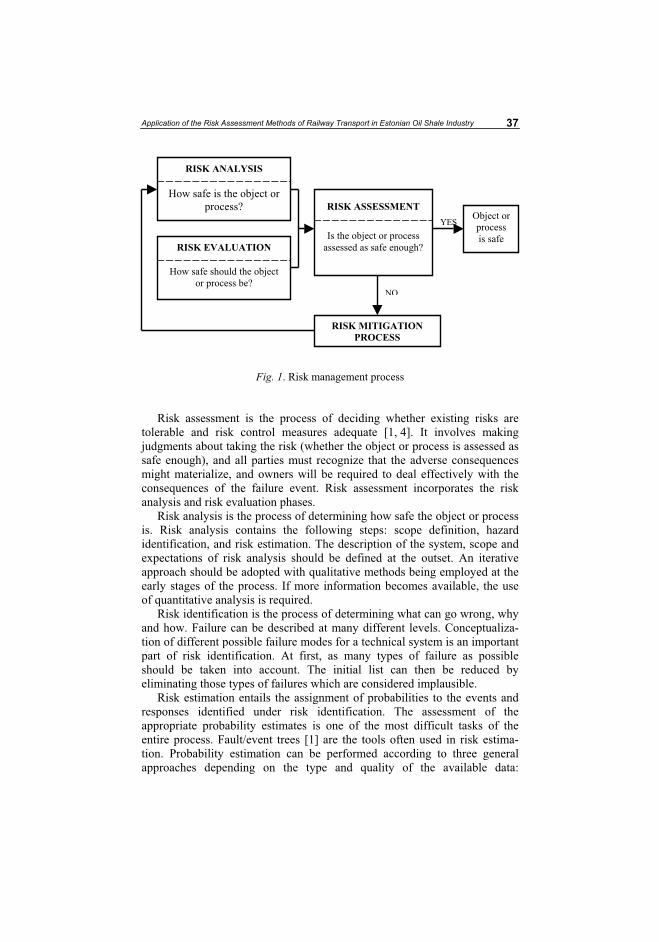
Application of the Risk Assessment Methods of Railway Transport in Estonian Oil Shale Industry 37
Fig. 1. Risk management process
Risk assessment is the process of deciding whether existing risks are tolerable and risk control measures adequate [1, 4]. It involves making judgments about taking the risk (whether the object or process is assessed as safe enough), and all parties must recognize that the adverse consequences might materialize, and owners will be required to deal effectively with the consequences of the failure event. Risk assessment incorporates the risk analysis and risk evaluation phases.
Risk analysis is the process of determining how safe the object or process is. Risk analysis contains the following steps: scope definition, hazard identification, and risk estimation. The description of the system, scope and expectations of risk analysis should be defined at the outset. An iterative approach should be adopted with qualitative methods being employed at the early stages of the process. If more information becomes available, the use of quantitative analysis is required.
Risk identification is the process of determining what can go wrong, why and how. Failure can be described at many different levels. Conceptualiza-tion of different possible failure modes for a technical system is an important part of risk identification. At first, as many types of failure as possible should be taken into account. The initial list can then be reduced by eliminating those types of failures which are considered implausible.
Risk estimation entails the assignment of probabilities to the events and responses identified under risk identification. The assessment of the appropriate probability estimates is one of the most difficult tasks of the entire process. Fault/event trees [1] are the tools often used in risk estima-tion. Probability estimation can be performed according to three general approaches depending on the type and quality of the available data:
RISK ANALYSIS
How safe is the object or process?
RISK EVALUATION
How safe should the object or process be?
RISK ASSESSMENT
Is the object or process assessed as safe enough?
Object orprocessis safe
RISK MITIGATION
PROCESS
YES
NO
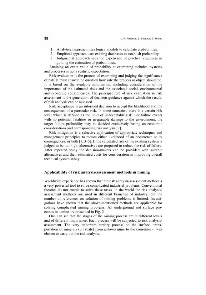
J.-R. Pastarus, S. Sabanov, T. Tohver 38
1. Analytical approach uses logical models to calculate probabilities. 2. Empirical approach uses existing databases to establish probability. 3. Judgmental approach uses the experience of practical engineers in
guiding the estimation of probabilities. Attaining an exact value of probability at examining technical systems
and processes is not a realistic expectation.Risk evaluation is the process of examining and judging the significance
of risk. It must answer the question how safe the process or object should be. It is based on the available information, including consideration of the importance of the estimated risks and the associated social, environmental and economic consequences. The principal role of risk evaluation in risk assessment is the generation of decision guidance against which the results of risk analysis can be assessed.
Risk acceptance is an informed decision to accept the likelihood and the consequences of a particular risk. In some countries, there is a certain risk level which is defined as the limit of unacceptable risk. For failure events with no potential fatalities or irreparable damage to the environment, the target failure probability may be decided exclusively basing on economic considerations and corresponding risk analysis [2].
Risk mitigation is a selective application of appropriate techniques and management principles to reduce either likelihood of an occurrence or its consequences, or both [1, 3–5]. If the calculated risk of the existing system is judged to be too high, alternatives are proposed to reduce the risk of failure. After repeated study the decision-makers can be provided with suitable alternatives and their estimated costs for consideration in improving overall technical system safety.
Applicability of risk analysis/assessment methods in mining
Worldwide experience has shown that the risk analysis/assessment method is a very powerful tool to solve complicated industrial problems. Conventional theories do not enable to solve these tasks. In the world the risk analysis/ assessment methods are used in different branches of industry, but the number of references on solution of mining problems is limited. Investi-gations have shown that the above-mentioned methods are applicable for solving complicated mining problems. All underground and surface pro-cesses in a mine are presented in Fig. 2.
One can see that the stages of the mining process are at different levels and of different importance. Each process will be subjected to risk analysis/ assessment. The very important tertiary process on the surface – trans-portation of minerals (oil shale) from Estonia mine to the consumer – was chosen to carry out the risk analysis.
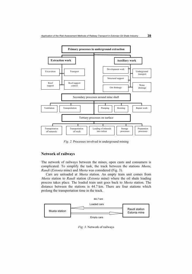
Application of the Risk Assessment Methods of Railway Transport in Estonian Oil Shale Industry 39
Fig. 2. Processes involved in underground mining
Network of railways
The network of railways between the mines, open casts and consumers is complicated. To simplify the task, the track between the stations Musta,Raudi (Estonia mine) and Musta was considered (Fig. 3).
Cars are unloaded at Musta station. An empty train unit comes from Musta station to Raudi station (Estonia mine) where the oil shale loading process takes place. The loaded train unit goes back to Musta station. The distance between the stations is 44.7 km. There are four stations which prolong the transportation time in the track.
Fig. 3. Network of railways
Primary processes in underground extraction
Extraction work Auxiliary work
Excavation
Roofsupport
Transport
Roof support control
Development work
Structural support
Gas drainage
Underground transport
Water drainage
Secondary processes around mine shaft
Ventilation
Tertiary processes on surface
Transportation Pumping Hoisting Repair work
Transportationof minerals
Transportation of rock
Loading of minerals into railcar
Storage processes
Preparationprocesses
Musta station
Empty cars
Raudi station Estonia mine
Loaded cars
44.7 km
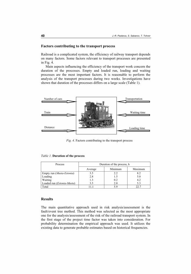
J.-R. Pastarus, S. Sabanov, T. Tohver 40
Factors contributing to the transport process
Railroad is a complicated system, the efficiency of railway transport depends on many factors. Some factors relevant to transport processes are presented in Fig. 4.
Main aspects influencing the efficiency of the transport work concern the duration of the processes. Empty and loaded run, loading and waiting processes are the most important factors. It is reasonable to perform the analysis of the transport processes during two weeks. Investigations have shown that duration of the processes differs on a large scale (Table 1).
Table 1. Duration of the process
Duration of the process, h Process
Average Minimum Maximum
Empty run (Musta-Estonia)LoadingWaiting Loaded run (Estonia-Musta)
3.52.81.33.5
2.21.50.22.0
8.25.04.25.3
Total 11.1 5.9 22.7
Results
The main quantitative approach used in risk analysis/assessment is the fault/event tree method. This method was selected as the most appropriate one for the analysis/assessment of the risk of the railroad transport system. In the first stage of the project time factor was taken into consideration. For probability determination the empirical approach was used. It utilizes the existing data to generate probable estimates based on historical frequencies.
Number of cars Transportationti
Distance
Traind
Waiting time
Loading time
Fig. 4. Factors contributing to the transport process
Distance
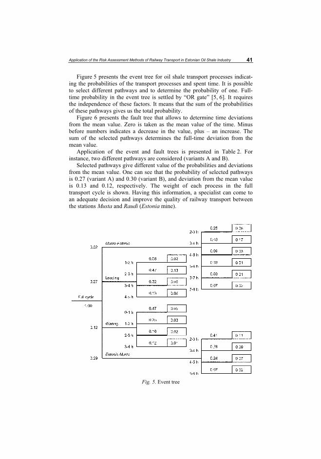
Application of the Risk Assessment Methods of Railway Transport in Estonian Oil Shale Industry 41
Figure 5 presents the event tree for oil shale transport processes indicat-ing the probabilities of the transport processes and spent time. It is possible to select different pathways and to determine the probability of one. Full-time probability in the event tree is settled by “OR gate” [5, 6]. It requires the independence of these factors. It means that the sum of the probabilities of these pathways gives us the total probability.
Figure 6 presents the fault tree that allows to determine time deviations from the mean value. Zero is taken as the mean value of the time. Minus before numbers indicates a decrease in the value, plus – an increase. The sum of the selected pathways determines the full-time deviation from the mean value.
Application of the event and fault trees is presented in Table 2. For instance, two different pathways are considered (variants A and B).
Selected pathways give different value of the probabilities and deviations from the mean value. One can see that the probability of selected pathways is 0.27 (variant A) and 0.30 (variant B), and deviation from the mean value is 0.13 and 0.12, respectively. The weight of each process in the full transport cycle is shown. Having this information, a specialist can come to an adequate decision and improve the quality of railway transport between the stations Musta and Raudi (Estonia mine).
Fig. 5. Event tree
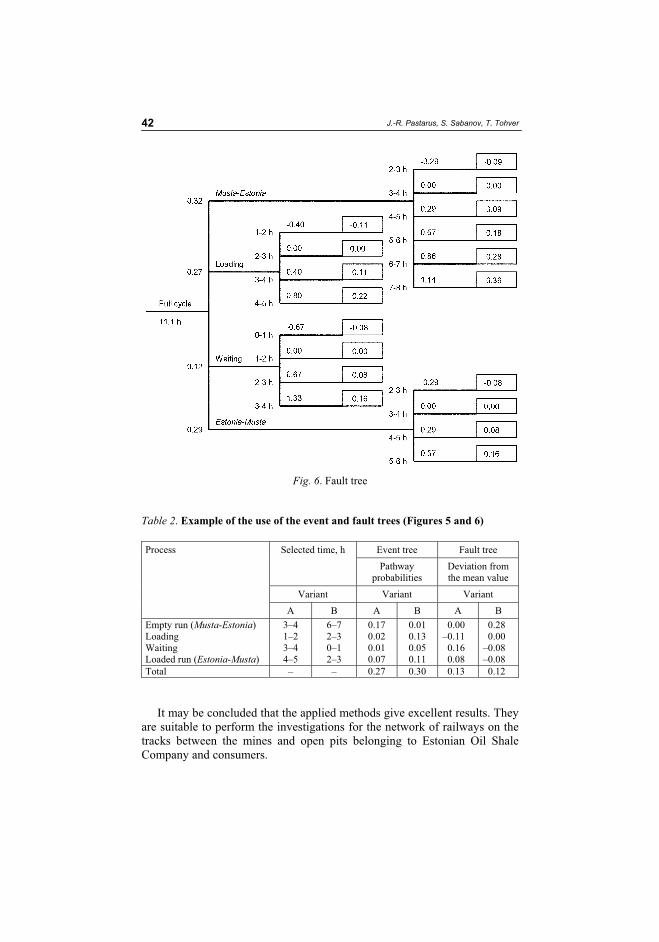
J.-R. Pastarus, S. Sabanov, T. Tohver 42
Fig. 6. Fault tree
Table 2. Example of the use of the event and fault trees (Figures 5 and 6)
Event tree Fault tree Selected time, h
Pathway probabilities
Deviation from the mean value
Variant Variant Variant
Process
A B A B A B
Empty run (Musta-Estonia)LoadingWaiting Loaded run (Estonia-Musta)
3–41–23–44–5
6–72–30–12–3
0.170.020.010.07
0.010.130.050.11
0.00–0.110.160.08
0.280.00
–0.08–0.08
Total – – 0.27 0.30 0.13 0.12
It may be concluded that the applied methods give excellent results. They are suitable to perform the investigations for the network of railways on the tracks between the mines and open pits belonging to Estonian Oil Shale Company and consumers.
Application of the Risk Assessment Methods of Railway Transport in Estonian Oil Shale Industry 43
Conclusions
As a result of this study, the following conclusions and recommendations can be made: 1. In Estonia oil shale is the most important mineral resource. Railway
transportation of oil shale is indispensable. Transportation of oil shale from mines and open casts to consumer by railway causes a lot of technical, economical, ecological and juridical problems.
2. The present study addresses the risk associated with transportation time. The primary interest of this study concerns evaluation of the usability of the method and evaluation of the probability of transportation time without a detailed assessment of the consequences.
3. Various factors relevant to transport have been determined. The event tree determines the probability of the efficiency of the transport system. The fault tree gives information about the deviation of the transport time from its mean value.
4. The risk analysis/assessment method is a powerful tool to solve complicated problems in the railway transport. The analysis shows that the used methods are applicable in conditions of Estonian railway systems. The results of the investigation are of particular interest for practical purposes.
5. Basing on the excellent results of this investigation, it is recommended to use the applied methods for the whole network of railways from mines and open casts to consumers.
Acknowledgments
Estonian Science Foundation (Grant No. 6558, 2006-2009) supported the research.
REFERENCES
1. Calow, P. Handbook of Environmental Risk Assessment and Management. – Oxford, Blackwell Science, 1998.
2. Hoeg, K. Performance evaluation, safety assessment and risk analysis for dams // Hydropower & Dams. 1996. No. 6. P. 47–63.
3. Lind, H. G. Mitigating the risk associated with underground coal pillar extrac-tion in South Africa // Mining Technology. Transaction of the Institutions of Mining and Metallurgy. 2004. Vol. 113, No. 4. P. 215–224.
4. Rowe, E. D. Risk Assessment Approaches and Methods // Society, Technology and Risk Assessment / J. Conrad (ed.). London: Academic Press, 1980. P. 3–29.

J.-R. Pastarus, S. Sabanov, T. Tohver 44
5. Williams, D. J., Loch, R. J., Vacher, C. Risk assessment applied to tunnel erosion of mine spoils // Proc. of the 11th Tailings and Mine Waste Conference. 10–13 October 2004, Vail, Colorado, USA, 2004, P. 63–70.
6. Rail safety research // Collection of the research reports. 1992–2005. www.rail-reg.gov.uk/server/show/nav.1184.
Presented by E. Reinsalu Received May 25, 2006
77
PAPER II. Lohk, M.; Väli, E.; Tohver, T.; Pastarus, J.-R., 2008. Surface miner
technology impact on the environment . In: 5th International Symposium "Topical
problems in the field of electrical and power engineering". Doctoral school of
energy and geotechnology: (Toim.) Lahtmets, R.. Tallinna Tehnikaülikool, 2008, 44
- 47.

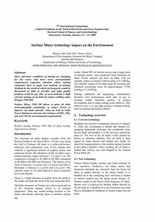
����
5th
International Symposium
„Topical Problems in the Field of Electrical and Power Engineering”,
Doctoral School of Energy and Geotechnology
Kuressaare, Estonia, January 14 – 19, 2008
Surface Miner technology impact on the Environment
�
Martin Lohk, Erik Väli, Tarmo TohverDepartment of Development, Estonian Oil Shale Company
Jüri-Rivaldo Pastarus Department of Mining, Tallinn University of Technology
[email protected], [email protected], [email protected]; [email protected]
Abstract
More and more conditions of mining are changing
for the worse and more strict environmental
requirements engender situation where mining
companies have to apply new methods of mining.
Methods in the result of which environment would be
threatened as little as possible and high quality
products could be got. One of such methods is high
selective mining of oil shale by surface milling cutter
Wirtgen 2500 SM.
Surface Miner 2500 SM allows to mine oil shale
environmentally sustainable, to reduce losses, to
improve oil shale calorific value as well as helps
Power Stations to decrease the volumes of SO2, NOx,
ash and CO2 by environmental requirements.
Keywords
Surface mining, Wirtgen 2500 SM, oil shale mining, high-selective mining
Introduction
The Estonian oil shale deposit stretches from the Russian border at the Narva River 130 km west along the Gulf of Finland. Oil shale is a yellowish-brown, relatively soft sedimentary rock of low density that contains a significant amount of organic matter and carbonate fossils. The thickness of the oil shale seam, without partings, ranges between 1.7 m and 2.3 m. The compressive strength is 20 MPa to 40 MPa compared to 40 MPa to 80 MPa for limestone. The density of oil shale is between 1.4 g/cm3 and 1.8 g/cm3 and that of limestone is between 2.2 g/cm3 and 2.6 g/cm3. The calorific value of oil shale deposit is fairly consistent across the deposit.
There is a slight decrease in quality from the north to the south, and from the west to the east across the area.
Oil-shale resources of Estonia are state-owned and lie in the Estonian deposit which is of national importance. State has issued mining licenses to the mines and pitches allowing them to perform mining
works. About 98% of electric power and a large share of thermal power were produced from Estonian oil shale. Power stations can burn oil shale with net calorific values of around 2.050 kcal/kg or 8.4 MJ/kg. Net calorific values of oil shale used for retorting and chemical processing must be approximately 2.700 kcal/kg or 11.4 MJ/kg.
Mining conditions are degreasing continuously, therefore new technologies must take in use to increase output materials quality, to protect environment and to make mining more effective. One effective way is to use high selective mining method, such as mining with Surface Miner.
2. Technology overview
2.1. Current technology
Draglines are used for overburden removal (1) (Figure 1). After the overburden is drilled and blasted (2), stripping equipment excavates the overburden from the oil shale and handles it in the previous mined-out strip (3). The roof of the oil shale is first cleared by dozers to minimize dilution. The oil shale is then ripped by large dozers and loaded into trucks by shovel for transportation to the crusher stations located at the surface facilities. After crushing, the oil shale is loaded into railway cars and shipped to the Estonia Power Plant [4].
2.2. New technology
Surface Miner breaks, crushes and loads material in one operation. Productive oil shale seams and limestone interbeds are extracted layer by layer, oil shale is loaded directly to the dump trucks or is handled on to the extracting seam and then is loaded by bucket loaders into the dump trucks (Figure 2). Further, trucks to the Power Plant transport oil shale. Barren rock is removed by Surface Miner directly to the pit heap or is handled on to the limestone layer and then is rehandled by bulldozer or bucket loader into pit heap.
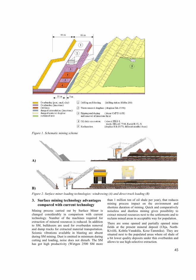
� ���
Figure 1. Schematic mining scheme �
A)
B)
Figure 2. Surface miner loading technologies: windrowing (A) and direct truck loading (B)
3. Surface mining technology advantages
compared with current technology
Mining process carried out by Surface Miner is changed considerably in comparison with current technology. Number of the machines required for extraction of mineral resources is reduced. In addition to SM, bulldozers are used for overburden removal and dump trucks for extracted material transportation. Seismic vibrations available in blasting are absent during SM mining. Dust is emitted in minimum during cutting and loading, noise does not disturb. The SM has got high productivity (Wirtgen 2500 SM more
than 1 million ton of oil shale per year), that reduces mining process impact on the environment and shortens duration of mining. Quick and comparatively noiseless and dustless mining gives possibility to extract mineral resources next to the settlements and to reclaim mined areas in acceptable way for population.
There are some opened and partially opened mine fields at the present mineral deposit (Ubja, North-Kiviõli, Kohtla-Vanaküla, Kose-Tammiku). They are situated next to the populated areas where oil shale of a bit lower quality deposits under thin overburden and allows to use high-selective extraction.
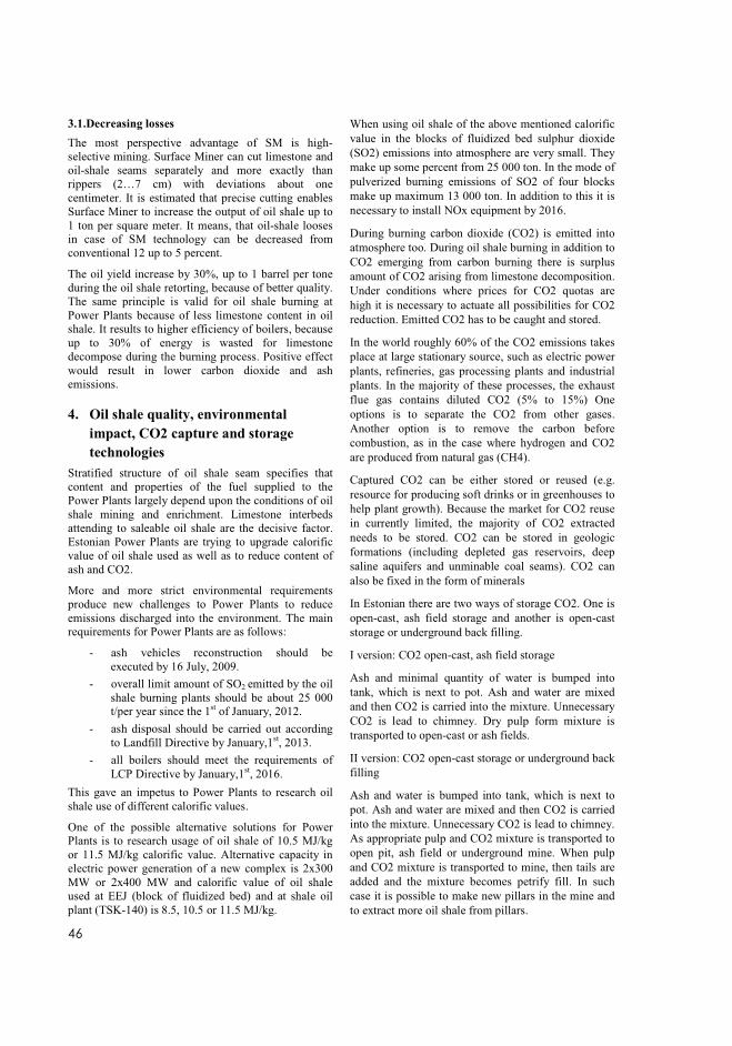
����
3.1.Decreasing losses
The most perspective advantage of SM is high-selective mining. Surface Miner can cut limestone and oil-shale seams separately and more exactly than rippers (2…7 cm) with deviations about one centimeter. It is estimated that precise cutting enables Surface Miner to increase the output of oil shale up to 1 ton per square meter. It means, that oil-shale looses in case of SM technology can be decreased from conventional 12 up to 5 percent.
The oil yield increase by 30%, up to 1 barrel per tone during the oil shale retorting, because of better quality. The same principle is valid for oil shale burning at Power Plants because of less limestone content in oil shale. It results to higher efficiency of boilers, because up to 30% of energy is wasted for limestone decompose during the burning process. Positive effect would result in lower carbon dioxide and ash emissions.
4. Oil shale quality, environmental
impact, CO2 capture and storage
technologies
Stratified structure of oil shale seam specifies that content and properties of the fuel supplied to the Power Plants largely depend upon the conditions of oil shale mining and enrichment. Limestone interbeds attending to saleable oil shale are the decisive factor. Estonian Power Plants are trying to upgrade calorific value of oil shale used as well as to reduce content of ash and CO2.
More and more strict environmental requirements produce new challenges to Power Plants to reduce emissions discharged into the environment. The main requirements for Power Plants are as follows:
- ash vehicles reconstruction should be executed by 16 July, 2009.
- overall limit amount of SO2 emitted by the oil shale burning plants should be about 25 000 t/per year since the 1st of January, 2012.
- ash disposal should be carried out according to Landfill Directive by January,1st, 2013.
- all boilers should meet the requirements of LCP Directive by January,1st, 2016.
This gave an impetus to Power Plants to research oil shale use of different calorific values.
One of the possible alternative solutions for Power Plants is to research usage of oil shale of 10.5 MJ/kg or 11.5 MJ/kg calorific value. Alternative capacity in electric power generation of a new complex is 2x300 MW or 2x400 MW and calorific value of oil shale used at EEJ (block of fluidized bed) and at shale oil plant (TSK-140) is 8.5, 10.5 or 11.5 MJ/kg.
When using oil shale of the above mentioned calorific value in the blocks of fluidized bed sulphur dioxide (SO2) emissions into atmosphere are very small. They make up some percent from 25 000 ton. In the mode of pulverized burning emissions of SO2 of four blocks make up maximum 13 000 ton. In addition to this it is necessary to install NOx equipment by 2016.
During burning carbon dioxide (CO2) is emitted into atmosphere too. During oil shale burning in addition to CO2 emerging from carbon burning there is surplus amount of CO2 arising from limestone decomposition. Under conditions where prices for CO2 quotas are high it is necessary to actuate all possibilities for CO2 reduction. Emitted CO2 has to be caught and stored.
In the world roughly 60% of the CO2 emissions takes place at large stationary source, such as electric power plants, refineries, gas processing plants and industrial plants. In the majority of these processes, the exhaust flue gas contains diluted CO2 (5% to 15%) One options is to separate the CO2 from other gases. Another option is to remove the carbon before combustion, as in the case where hydrogen and CO2 are produced from natural gas (CH4).
Captured CO2 can be either stored or reused (e.g. resource for producing soft drinks or in greenhouses to help plant growth). Because the market for CO2 reuse in currently limited, the majority of CO2 extracted needs to be stored. CO2 can be stored in geologic formations (including depleted gas reservoirs, deep saline aquifers and unminable coal seams). CO2 can also be fixed in the form of minerals
In Estonian there are two ways of storage CO2. One is open-cast, ash field storage and another is open-cast storage or underground back filling.
I version: CO2 open-cast, ash field storage
Ash and minimal quantity of water is bumped into tank, which is next to pot. Ash and water are mixed and then CO2 is carried into the mixture. Unnecessary CO2 is lead to chimney. Dry pulp form mixture is transported to open-cast or ash fields.
II version: CO2 open-cast storage or underground back filling
Ash and water is bumped into tank, which is next to pot. Ash and water are mixed and then CO2 is carried into the mixture. Unnecessary CO2 is lead to chimney. As appropriate pulp and CO2 mixture is transported to open pit, ash field or underground mine. When pulp and CO2 mixture is transported to mine, then tails are added and the mixture becomes petrify fill. In such case it is possible to make new pillars in the mine and to extract more oil shale from pillars.
� ���
5. Conclusions
Mining conditions changing for the worse more and more make a claim for new and environment-friendly mining technologies. High selective mining by Surface Miner 2500 is one of such possibilities. Surface Miner 2500 allows to mine oil shale close to the towns and populated areas quickly and with small disturbance, to mine oil shale without blasting, to restore mined areas with suitable microrelief, to get higher productivity, to produce oil shale of higher quality. Calorific value of the raw material remains in the range of 8.4-11.4 MJ/kg. Surface Miner 2500 allows to use extracted oil shale without preparation and to generate electric energy in new fluidized bed boilers. Because of that emissions of CO2 are reduced by 20 % and ash amount is reduced up to 15 %.
Strict environmental standards gave an impetus to Power Plants to research oil shale use of different calorific value. Alternative solution is to study oil shale use of 10.5 or 11.5 MJ/kg.
Use of oil shale of that calorific value in fluidized bed blocks and pulverized burning boilers keeps sulphur dioxide (SO2) content in the permitted limits of 25 000 ton. In addition to that NOx emissions into the air should be reduced by 2016.
More and more attention is turned to decrease CO2 problems and to work out new solutions. In Estonian there are two ways of storage CO2. One is open-cast, ash field storage and another is open-cast storage or underground back filling.
Acknowledgment
Estonian Science Foundation (Grant No. 6558) supported the research.
References 1. Ots. A, Soosaar. S, Rootamm. R, Reinsalu. E,
Pihu. T. Kasutustehnoloogiale vastava optimaalse koostisega põlevkvi tootmise tehnoloogilised võimalused ning majandusliku otstarbekuse analüüs I etapp.Tallinn, 2007.
2. Nikitin O., Väli E., Sabanov S., Pastarus, J.-R. 2007. The surface miner sustainable technology introduction for oil-shale mining in Estonia. In: 6th International conference “Environment.Technology.Resources", Rezekne, June 20-22. p. 55-61.
3. Nikitin. O, Väli.E, Pastarus. J-R, Sabanov.
S.2007. The Surface Miner Sustainable Oil-
Shale Mining Technology Testing Results in
Estonia. (MPES-2007). 11-13 September 2007, Bangkok, Tailand, in print.
4. Eesti Põlevkivi 15-Year Mining Plan, Germany, 2001.
5. Karu. V. Kaevandavate ettevõtete põlevkivivaru inventuur. Estonia kaevanduse lõunaosas paikneva põlevkivivaru ümberhindamise põhjendus, Tallinn, 2004
6. A “Down-to-Earth” Solution to Climate Change, (2007), pp. 1-4. Available at http://www.co2net.com/infocentre/brochures/CO2NET-Public-Brochure-English.pdf
�
83
PAPER III. Sabanov, S.; Tohver, T.; Väli, E.; Nikitin, O.; Pastarus, J.-R., 2008.
Geological aspects of risk management in oil shale mining. Oil Shale, 25(2S), 145 -
152.

Oil Shale, 2008, Vol. 25, No. 2 Special, pp. 145–152 ISSN 0208-189X doi: 10.3176/oil.2008.2S.06 © 2008 Estonian Academy Publishers
GEOLOGICAL ASPECTS OF RISK MANAGEMENT
IN OIL SHALE MINING
S. SABANOV, T. TOHVER, E. VÄLI, O. NIKITIN,J.-R. PASTARUS*
Department of Mining, Tallinn University of Technology 5, Ehitajate Rd., 19086 Tallinn, Estonia
The paper deals with risk management problems in Estonian oil shale mines. Investigations are focused on application of the method to determination of the quality of geological data. Various factors relevant to mining technology in Estonian oil shale deposit have been determined. For risk estimation, the empirical and judgmental approaches and the event tree were used. They allow determining the probability of the occurrence of geological features and its influence on the mining process. Analysis of obtained results showed that it is necessary to elaborate special methods for determination of the geo-logical conditions in the mining area. The obtained information affords specialists to improve the quality of geological information and consequently the mine work efficiency. The analysis shows that the used method is applic-able in conditions of Estonian oil shale industry. The results of the investiga-tion are of particular interest for practical purposes.
Introduction
In Estonia the most important mineral resource is oil shale. Oil shale industry of Estonia provides a significant contribution to the country’s economy. Underground and surface mining in the Estonian oil shale deposit causes a large number of technical, economical, geological, ecological and juridical problems, which cannot be solved on conventional theoretical basis. Risk management is a most powerful tool to solve complicated mining problems. The data, which have been accumulating in the last 40–50 years, concern the experience obtained by oil shale excavating and provide a good basis for investigations.
This study addresses risks associated with stability of the immediate roof in the mines Estonia and Viru, depending mostly on the geological feature. The primary interest of this study concerns evaluating the usability of the
* Corresponding author: e-mail [email protected]
S. Sabanov et al. 146
method and estimating the probability of failure without a detailed assess-ment of its consequences. The study is based on the world’s and Estonian experience. As an example of application, the risk analysis of Estonian oil shale mines has been conducted.
Risk management involves making a judgment about taking a risk, and all parties must recognize the possibility of adverse consequences which might materialize [1–4]. Therefore, owners will be required to deal effectively with the consequences of a failure event. Prevention of the hazardous situa-tion is more moral, ethical and economic than facing the adverse con-sequences. Having received the information, the management of a mine or open cast can come to adequate political and strategic decisions. The mitiga-tion process will reduce the adverse consequences [1, 5]. Investigations have shown that the share of risk relevant to geological data in mining and environmental protection is very large. It is known that rock mass properties vary and depend on its location. It is impossible to determine exactly all the geological features. The reliability of geological data determines the efficiency and safety of mining and environmental impact. It includes bed-ding, underground and surface water conditions, existence of karst, joint systems, etc.
Some of the various geological factors relevant to Estonian oil shale mines have been determined. For risk estimation, the judgmental and empirical approaches and event tree have been used. The risk management method allows predicting the probability of failure of the immediate roof in the location of interest. Getting the information allows specialists to mitigate negative influence of risks on the excavation process and environment.
Analysis showed that the risk management method used is applicable to Estonian oil shale mines, which are of particular interest for practical purposes.
Theoretical background
In the world, risk management methods are used in different branches of industry and for many different technical systems. In Estonia, including Eesti Põlevkivi Ltd, risk management methods are focused on health safety problems. There is less information about the application of risk manage-ment methods to geological conditions and technological processes. In spite of the varied terminology, there is general agreement on the basic require-ments [1, 3, 5, 6]. The terminology and risk management/assessment methodology used in the frame of this project are presented below.
Risk can be defined as the likelihood or expected frequency of a specified adverse consequences [1, 4]. Risk management is the systematic application of management policies, procedures and practices to the task of identifying, analyzing, assessing, treating and monitoring risk [1, 3, 4]. Having obtained the risk information, a decision-maker must come to a decision.
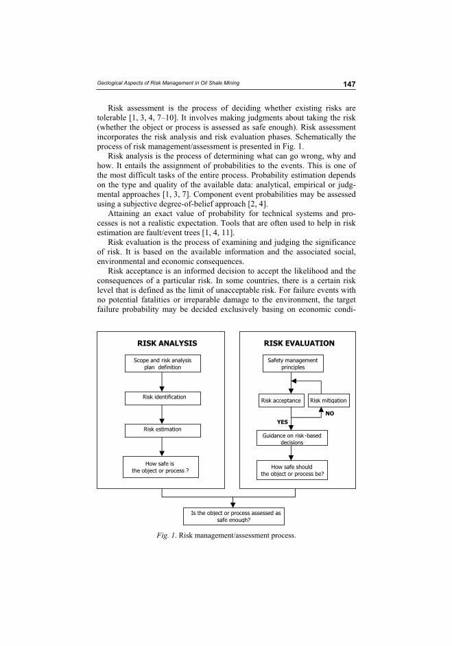
Geological Aspects of Risk Management in Oil Shale Mining 147
Risk assessment is the process of deciding whether existing risks are tolerable [1, 3, 4, 7–10]. It involves making judgments about taking the risk (whether the object or process is assessed as safe enough). Risk assessment incorporates the risk analysis and risk evaluation phases. Schematically the process of risk management/assessment is presented in Fig. 1.
Risk analysis is the process of determining what can go wrong, why and how. It entails the assignment of probabilities to the events. This is one of the most difficult tasks of the entire process. Probability estimation depends on the type and quality of the available data: analytical, empirical or judg-mental approaches [1, 3, 7]. Component event probabilities may be assessed using a subjective degree-of-belief approach [2, 4].
Attaining an exact value of probability for technical systems and pro-cesses is not a realistic expectation. Tools that are often used to help in risk estimation are fault/event trees [1, 4, 11].
Risk evaluation is the process of examining and judging the significance of risk. It is based on the available information and the associated social, environmental and economic consequences.
Risk acceptance is an informed decision to accept the likelihood and the consequences of a particular risk. In some countries, there is a certain risk level that is defined as the limit of unacceptable risk. For failure events with no potential fatalities or irreparable damage to the environment, the target failure probability may be decided exclusively basing on economic condi-
Scope and risk analysis
plan definition
Risk identification
Risk estimation
Safety management
principles
Guidance on risk -based
decisions
Is the object or process assessed as
safe enough?
How safe is
the object or process ?How safe should
the object or process be?
Risk mitigation
RISK ANALYSIS RISK EVALUATION
NO
YES
Risk acceptance
Fig. 1. Risk management/assessment process.
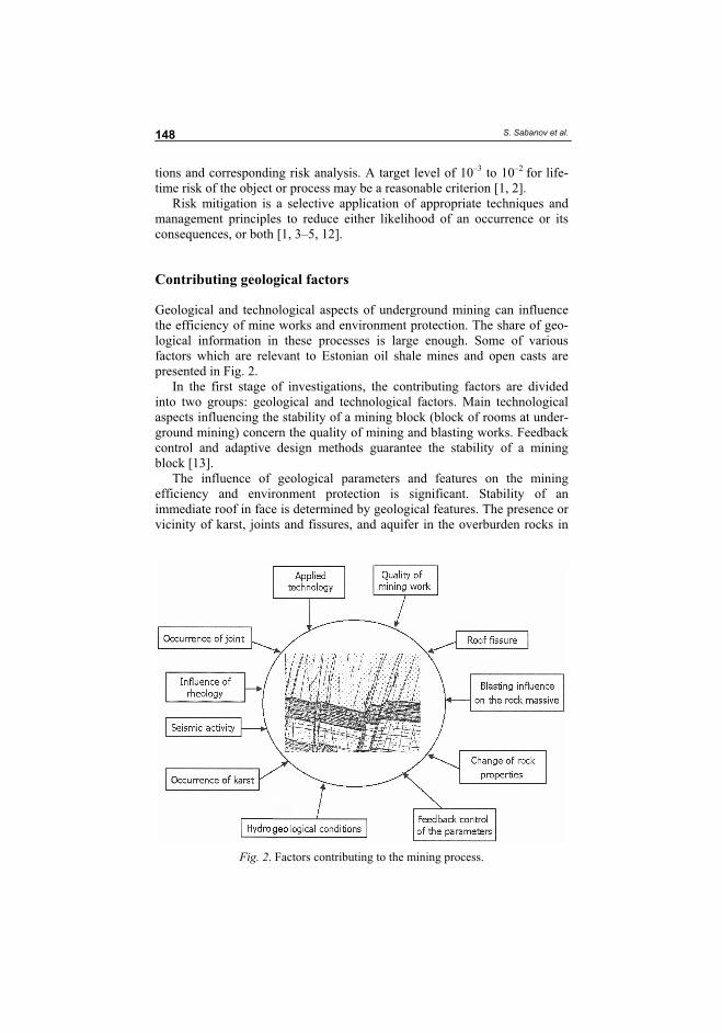
S. Sabanov et al. 148
tions and corresponding risk analysis. A target level of 10–3 to 10–2 for life-time risk of the object or process may be a reasonable criterion [1, 2].
Risk mitigation is a selective application of appropriate techniques and management principles to reduce either likelihood of an occurrence or its consequences, or both [1, 3–5, 12].
Contributing geological factors
Geological and technological aspects of underground mining can influence the efficiency of mine works and environment protection. The share of geo-logical information in these processes is large enough. Some of various factors which are relevant to Estonian oil shale mines and open casts are presented in Fig. 2.
In the first stage of investigations, the contributing factors are divided into two groups: geological and technological factors. Main technological aspects influencing the stability of a mining block (block of rooms at under-ground mining) concern the quality of mining and blasting works. Feedback control and adaptive design methods guarantee the stability of a mining block [13].
The influence of geological parameters and features on the mining efficiency and environment protection is significant. Stability of an immediate roof in face is determined by geological features. The presence or vicinity of karst, joints and fissures, and aquifer in the overburden rocks in
Fig. 2. Factors contributing to the mining process.
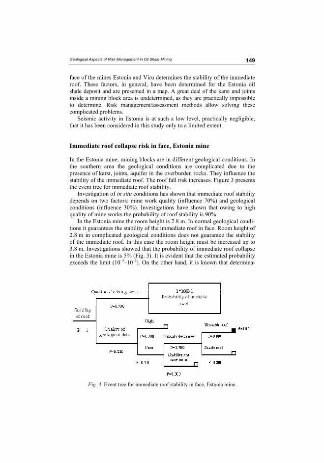
Geological Aspects of Risk Management in Oil Shale Mining 149
face of the mines Estonia and Viru determines the stability of the immediate roof. These factors, in general, have been determined for the Estonia oil shale deposit and are presented in a map. A great deal of the karst and joints inside a mining block area is undetermined, as they are practically impossible to determine. Risk management/assessment methods allow solving these complicated problems.
Seismic activity in Estonia is at such a low level, practically negligible, that it has been considered in this study only to a limited extent.
Immediate roof collapse risk in face, Estonia mine
In the Estonia mine, mining blocks are in different geological conditions. In the southern area the geological conditions are complicated due to the presence of karst, joints, aquifer in the overburden rocks. They influence the stability of the immediate roof. The roof fall risk increases. Figure 3 presents the event tree for immediate roof stability.
Investigation of in situ conditions has shown that immediate roof stability depends on two factors: mine work quality (influence 70%) and geological conditions (influence 30%). Investigations have shown that owing to high quality of mine works the probability of roof stability is 90%.
In the Estonia mine the room height is 2.8 m. In normal geological condi-tions it guarantees the stability of the immediate roof in face. Room height of 2.8 m in complicated geological conditions does not guarantee the stability of the immediate roof. In this case the room height must be increased up to 3.8 m. Investigations showed that the probability of immediate roof collapse in the Estonia mine is 5% (Fig. 3). It is evident that the estimated probability exceeds the limit (10–3–10–2). On the other hand, it is known that determina-
Fig. 3. Event tree for immediate roof stability in face, Estonia mine.
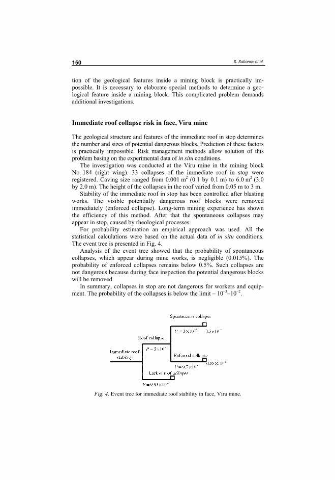
S. Sabanov et al. 150
tion of the geological features inside a mining block is practically im-possible. It is necessary to elaborate special methods to determine a geo-logical feature inside a mining block. This complicated problem demands additional investigations.
Immediate roof collapse risk in face, Viru mine
The geological structure and features of the immediate roof in stop determines the number and sizes of potential dangerous blocks. Prediction of these factors is practically impossible. Risk management methods allow solution of this problem basing on the experimental data of in situ conditions.
The investigation was conducted at the Viru mine in the mining block No. 184 (right wing). 33 collapses of the immediate roof in stop were registered. Caving size ranged from 0.001 m2 (0.1 by 0.1 m) to 6.0 m2 (3.0by 2.0 m). The height of the collapses in the roof varied from 0.05 m to 3 m.
Stability of the immediate roof in stop has been controlled after blasting works. The visible potentially dangerous roof blocks were removed immediately (enforced collapse). Long-term mining experience has shown the efficiency of this method. After that the spontaneous collapses may appear in stop, caused by rheological processes.
For probability estimation an empirical approach was used. All the statistical calculations were based on the actual data of in situ conditions. The event tree is presented in Fig. 4.
Analysis of the event tree showed that the probability of spontaneous collapses, which appear during mine works, is negligible (0.015%). The probability of enforced collapses remains below 0.5%. Such collapses are not dangerous because during face inspection the potential dangerous blocks will be removed.
In summary, collapses in stop are not dangerous for workers and equip-ment. The probability of the collapses is below the limit – 10–3–10–2.
Fig. 4. Event tree for immediate roof stability in face, Viru mine.
Geological Aspects of Risk Management in Oil Shale Mining 151
Discussion
Risk management/assessment methods allow determining the probability of the immediate roof collapse using the event tree. Having got this informa-tion, the mine management may decide about taking risks: are they accept-able or not; are they dangerous for workers and/or for the environment? If this risk is not acceptable, the mine management must preview the risk mitigations methods: use of appropriate techniques or/and management principles to reduce either likelihood of an occurrence or its consequences, or both. In the Estonia mine the room height of 3.8 m reduces the probability of an immediate roof collapse and its negative consequences, being the only true solution.
On the other hand, information about the probability of an immediate roof collapse offers the scientists objects for future investigations.
Conclusions
As a result of this study, the following conclusions and recommendations can be made:
1. Geological and technological factors relevant to immediate roof stability have been determined. The share of geological factors, such as karst, joints, fissures, aquifer, etc. in this process is large.
2. Geological risks by underground mining are estimated by empirical and judgmental approaches. In the investigations the event tree was used.
3. The influence of the quality of geological data on the mining process is significant. It is necessary to elaborate special methods to determine the geological features inside a mining block.
4. The risk management method is a powerful tool to solve complicated mining problems. The analysis showed that the method is applicable in conditions of Estonia oil shale deposit. The results of the investi-gation are of particular interest for practical purposes.
Acknowledgements
Estonian Science Foundation (Grant No. 6558, “Concept and methods of risk management in mining”) supported the research. It is also a part of the project No SF0140093s08 of the Estonian Ministry of Education and Research.
S. Sabanov et al. 152
REFERENCES
1. Calow, P. Handbook of environmental risk assessment and management. – Oxford, Blackwell Science, 1998.
2. Hoeg, K. Performance evaluation, safety assessment and risk analysis for dams // Hydropower & Dams. 1996. No. 6. P. 69–87.
3. Rowe, E. W. D. Risk assessment approaches and methods. // Society, Technol-ogy and Risk Assessment / J. Conrad (ed.). London: Academic Press, 1980. P. 3–29.
4. Tint, P. Risk Assessment at Working Place. Chemical Risk. Published by TUT, Tallinn, 1999 [in Estonian].
5. Lind, H. G. Mitigating the risk associated with underground coal pillar extrac-tion in South Africa // Mining Technology. Transaction of the Institutions of Mining and Metallurgy. 2004. Vol. 113, No. 4. P. 215–224.
6. Kristjuhan, Ü. Actual Problems of Catastrophes and Risk Management I, II. Published by TUT, Tallinn 1997, 1999 [in Estonian].
7. Williams, D. J., Loch, R. J., Vacher, C. Risk assessment applied to tunnel erosion of mine spoils // Proc. of the 11th Tailings and Mine Waste Conference. 10–13 October 2004, Vail, Colorado, USA, 2004. P. 63–70.
8. Grahm, L. P., Bartsch, M. Risk analysis safety assessment for use at Swedish dams // Symposium: Research and development in the field of dams. Crans-Montana, Switzerland, 7–9 September 1995. P. 12–19.
9. Andrews, J. D., Moss, T. R. Reliability and Risk Assessment. – Longman, Harlow, UK, 1993.
10. Pastakia, C., Jensen, A. The rapid impact assessment matrix (RIAM) for EIA // Environ impact Asses rev., New York, 1998. P. 461–482.
11. Alexieva, T. The Benefits of the Risk Assessment to the Mining Industry. Tailings and Mine Waste. – Balkema, Tokyo, 2002. 295 p.
12. Duzgun, H. S. B., Einstein, H. H. Assessment and management of roof fall risks in underground coal mines // Safety Science. 2004. No. 42. P. 23–41.
13. Pastarus, J.-R., Sabanov, S. A method for securing working mining block stability in Estonian oil shale mines // Engineering. 2005. Vol. 11, No. 1. P. 59–68.
Received September 20, 2007
93
PAPER IV. Pastarus, J.-R.; Tohver, T.; Väli, E.; 2009. Backfilling and waste
management in Estonian oil shale indrusty. In: Future energy solutions: International
Oil Shale Symposium, Tallinn, Estonia, June 8-11, 2009. (Toim.) Sirli Peda. Tallinn,
Estonia: Tallinn, EE, 2009, 48-49.

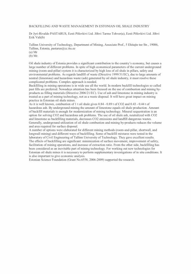
BACKFILLING AND WASTE MANAGEMENT IN ESTONIAN OIL SHALE INDUSTRY
Dr Jyri-Rivaldo PASTARUS, Eesti Põlevkivi Ltd. Jõhvi Tarmo Tohver(a), Eesti Põlevkivi Ltd. JõhviErik Vali(b)
Tallinn University of Technology, Department of Mining, Associate Prof., 5 Ehitajte tee Str., 19086,Tallinn, Estonia, [email protected](a) Mr(b) Mr.
Oil shale industry of Estonia provides a significant contribution to the country’s economy, but causes alarge number of different problems. In spite of high economical parameters of the current undergroundmining (room-and-pillar) system it is characterized by high loss of oil shale in pillars, safety andenvironmental problems. As regards landfill of waste (Directive 1999/31/EC), due to large amounts ofneutral (limestone) and hazardous waste (ash) generated by oil shale industry, it must resolve thesecomplicated problems. Complex approach is needed.Backfilling in mining operations is in wide use all the world. In modern backfill technologies so calledpast fills are preferred. Nowadays attention has been focused on the use of combustion and mining by-products as filling materials (Directive 2006/21/EC). Use of ash and limestone in mining industry istreated as a part of mining technology, not as a waste disposal. It will have great impact on miningpractice in Estonian oil shale mines.As it is well known, combustion of 1 t oil shale gives 0.84 - 0.89 t of CO2 and 0.43 - 0.44 t ofhazardous ash. By underground mining the amount of limestone equals oil shale production. Amountof backfill materials is enough for modernization of mining technology. Mineral sequestration is anoption for solving CO2 and hazardous ash problems. The use of oil shale ash, neutralized with CO2and limestone as backfilling materials, decreases CO2 emissions and landfill dangerous wastes.Generally, underground utilization of oil shale combustion and mining by-products reduces the volumeand area required for surface disposal.A number of options were elaborated for different mining methods (room-and-pillar, shortwall, andlongwall mining) and different ways of backfilling. Some of backfill mixtures were tested in thelaboratory of Civil Engineering of Tallinn University of Technology. They gave excellent results.The effects of backfilling are significant: minimization of surface movement, improvement of safety,facilitation of mining operations, and increase of extraction ratio. From the other side, backfilling hasbeen considered as an inevitable part of mining technology. For working out new technologies forEstonian oil shale mines it is necessary to perform supplementary investigations of in situ conditions. Itis also important to give economic analysis.Estonian Science Foundation (Grant No.6558, 2006-2009) supported the research.

97
PAPER V. Tohver, T.; 2010. Fine aggregates produced from oil shale mining waste
rock for backfilling the mined areas. Проблемы Недропользования. Санкт-
Петербургский Государственный Горный Инс, 189, 104 – 106.

FINE AGGREGATES PRODUCED FROM OIL SHALE MINING WASTE ROCK FOR
BACKFILLING THE MINED AREAS
Tarmo Tohver
Eesti Energia Kaevandused AS (Estonian Energy Mining Company)
41533 Jõhvi, 10 Jaama Str. Estonia
Introduction
The Estonian oil shale deposit stretches from the Russian border at the Narva River 130 km west
along the Gulf of Finland. Oil shale is a yellowish-brown, relatively soft sedimentary rock of low
density that contains a significant amount of organic matter and carbonate fossils. The productive
oil shale stratum consist oil shale and limestone layers and limestone concretions.
The thickness of the oil shale seam, without partings, ranges between 1.7 m and 2.3 m. The
compressive strength of oil shale is 15 MPa to 40 MPa compared to 40 MPa to 80 MPa for
limestone. The density of oil shale is between 1400 kg/cm3 and 1800 kg/cm3 and that of
limestone is between 2200 kg/cm3 and 2600 kg/cm3. The calorific value of oil shale deposit is
fairly consistent across the deposit. There is a slight decrease in quality from the north to the
south, and from the west to the east across the area. More than 90% of electric power and a large
share of thermal power were produced from Estonian oil shale. Power stations consume oil shale
with net calorific values of around 8.4 MJ/kg. Net calorific values of oil shale used for retorting
and chemical processing must be approximately from 8.4 MJ/kg to 11.4 MJ/kg.
About 15 million tons of oil shale is extracted annually, 50% is mined in underground mines and
50% is mined in surface mines. Major part of waste rock from surface mine is used for mining
site restoration. Waste rock from underground mine is about 5 million tons per year. Waste rock
from oil shale mining is a material for producing aggregate used in road building and civil
engineering. Data for this study is collected from 1989 to 2009.
Properties of oil shale mining waste rock
Limestone layers and concretion are separated from oil shale to achieve the required calorific
value (8,4 – 11,4 MJ/kg) of trade oil shale. Some properties of oil shale mining waste rock
particle size range 25/125 and 125/300 mm are:
Calorific value (GOST 147-95) Qdb = 1,8 – 2,2 MJ/kg [1];
Resistance to fragmentation (EN 1097-2:1998) = LA35 – LA40.
Aggregate production from oil shale mining waste rock
Aggregate production plant consist many stage of crushing and screening. Best type of crusher
for oil shale mining waste rock is the impact crusher. Grains of aggregate are crushed against
crusher parts and against each other, producing good cube shaped product. Impact crushers are
characterized by a high reduction ratio and are used for selective crushing, it liberates hard
coarser aggregate (limestone) from soft finer aggregate which consist large amount of oil shale.
Resistance to fragmentation and freeze resistance of coarse aggregate will increase in every stage
of crushing and screening and fine aggregate passing the screen is characterized with low
resistance to fragmentation and freezing. Low resistance to freezing of fine aggregate is caused
by high content of oil shale. Yield of fine-grained material is up to 50%.
Utilization of aggregate
Coarser aggregate retained in the feed will crushed again and finer aggregate will screened. There
are usually two or three stages of crushing.
Properties of coarse aggregate, particle size range 4/63 mm:
Calorific value (GOST 147-95) Qdb = 0,5 – 2,0 MJ/kg;
Resistance to fragmentation (EN 1097-2:1998) is LA30 – LA40;
Destructibility (GOST 8268 p 8) is M600 – M800;
Resistance to freezing and thawing (EN 1367-1:2007) is F � 2 %;
Frost resistance (GOST 8269) is 15 or 25 cycles.
Coarse aggregate is used for road building and in civil engineering.
Properties of fine aggregate, particle size range 0/10 mm:
Calorific value (GOST 147-95) Qdb = 2,0 – 4,0 MJ/kg;
Resistance to freezing and thawing (EN 1367-1:2007) F � 4 %.
According to standard EN 12620 „Aggregates for concrete“ Annex F table F.1 aggregate with
frost resistance F � 4 % is usable in frost free or dry situation. Utilization of fine aggregate form
oil shale mining waste rock is limited and using in frosted conditions is impossible. Temperature
in oil shale underground mine excavated areas is 6 ºC.
Laboratory of Civil Engineering of Tallinn University of Technology has tested different backfill
mixtures of fine aggregate particle size range 0/10 mm and ashes from combustion of oil shale.
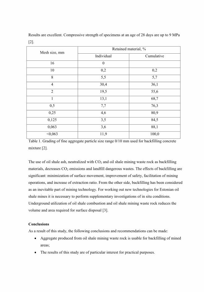
Results are excellent. Compressive strength of specimens at an age of 28 days are up to 9 MPa
[2].
Mesh size, mm Retained material, %
Individual Cumulative
16 0
10 0,2 0,2
8 5,5 5,7
4 30,4 36,1
2 19,5 55,6
1 13,1 68,7
0,5 7,7 76,3
0,25 4,6 80,9
0,125 3,5 84,5
0,063 3,6 88,1
<0,063 11,9 100,0
Table 1. Grading of fine aggregate particle size range 0/10 mm used for backfilling concrete
mixture [2].
The use of oil shale ash, neutralized with CO2 and oil shale mining waste rock as backfilling
materials, decreases CO2 emissions and landfill dangerous wastes. The effects of backfilling are
significant: minimization of surface movement, improvement of safety, facilitation of mining
operations, and increase of extraction ratio. From the other side, backfilling has been considered
as an inevitable part of mining technology. For working out new technologies for Estonian oil
shale mines it is necessary to perform supplementary investigations of in situ conditions.
Underground utilization of oil shale combustion and oil shale mining waste rock reduces the
volume and area required for surface disposal [3].
Conclusions
As a result of this study, the following conclusions and recommendations can be made:
Aggregate produced from oil shale mining waste rock is usable for backfilling of mined
areas;
The results of this study are of particular interest for practical purposes.
Acknowledgement
Estonian Science Foundation (Grant No. 7499 and Grant No. 8123) supported the research.
REFERENCES
1. Adamson, A. (1989). Põlevkivi tootmisjääkidest valmistatava ehituskillustiku kasutamise
võimaluste uurimine. Aruanne, (töö šiffer) 955.
2. TTÜ Ehitustootluse Instituudi Ehitusmaterjalide teadus- ja katselaboratoorium. (2008)
Põlevkivi kaevandamis- ja töötlemisjääkide kasutamine tagasitäiteks kaevandatud aladel.
Aruanne. Leping nr 8008.
3. Pastarus, J-R. (2009). Põlevkivi kaevandamis- ja töötlemisjääkide kasutamine
tagasitäiteks kaevandatud aladel – katsetööde metoodika väljatöötamine. Aruanne. Leping
nr 9090.
103
PAPER VI. Tohver, T.; 2010. Oil shale waste rock aggregate properties which are
depending on content of oil shale. In: 9th International Symposium "Topical
Problems in the Field of Electrical and Power Engineering". Pärnu, Estonia, 14.06.-
19.06.2010. (Toim.) Lahtmets, R.. Estonian Society of Moritz Hermann Jacobi,
2010, 59 - 62.

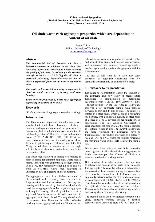
59
9th
International Symposium
„Topical Problems in the Field of Electrical and Power Engineering“
Pärnu, Estonia, June 14-19, 2010
Oil shale waste rock aggregate properties which are depending on
content of oil shale
Tarmo Tohver Tallinn University of Technology
Abstract
The commercial bed of Estonian oil shale -
kukersite consists in addition to oil shale also
limestone layers and concretions which decrease
the quality of oil shale. In order to get the required
calorific value 8.4 – 11.4 MJ/kg the oil shale is
extracted selectively, high-selectively or the oil
shale is separated from run of mine in separation
plant.
The waste rock extracted in mining or separated in
plant is usable in civil engineering and road
building.
Some physical properties of waste rock aggregates
depending on content of oil shale.
Keywords
Oil shale, waste rock, aggregate, selective crushing
Introduction
The Estonia most important mineral resource is a specific kind of oil shale – kukersite. Oil shale is mined in underground mines and in open casts. The commercial bed of oil shale consists in addition to oil shale layers (A, A’, B, C, D, E, F1) also limestone layers (A/A’, A’/B, B/C, C/D, D/E, E/F1) and concretions which decrease the quality of oil shale. In order to get the required calorific value 8.4 – 11.4 MJ/kg the oil shale is extracted selectively, high-selectively or oil shale is separated from run of mine in separation plant.
The waste rock extracted in mining or separated in plant is usable for different purposes. Waste rock is mainly limestone with compressive strength from 40 to 80 MPa. The compressive strength of oil shale is from 20 to 40 MPa. Waste rock aggregate is utilisated in civil engineering and road building.
The aggregate produced from oil shale waste rock is characterized with relatively low resistance to fragmentation and low resistance to freezing and thawing which is caused by fine and weak oil shale particles in aggregate. In order to get the aggregate with required quality, oil shale particles have to be separated from limestone or oil shale occurrence in aggregate has to be excluded. The way the oil shale is separated from limestone is called selective crushing where aggregated grains of limestone and
oil shale are crushed against plates of impact crusher and against other grains and fine and crushed grains will be screened out. On screen retained aggregate is crushed again until properties of aggregate match the requirements.
The task of this study is to show that some properties of aggregate accordance with EN standards are depending on content of oil shale.
1 Resistance to fragmentation
Resistance to fragmentation shows the strength of the aggregate and how easily it breaks apart. Resistance to fragmentation is determined accordance with EVS-EN 1097-2:1998+A1:2006. The test method for the Los Angeles Coefficient involves a test aggregate sample with particles between 10 mm and 14 mm in size. The sample is rotated in a steel drum, which contains a projecting shelf inside, with a specified quantity of steel balls, at a speed of 31 to 33 revolutions per minute for 500 revolutions. The Los Angeles Coefficient is calculated from the proportion of the sample reduced to less than 1.6 mm in size. The lower the coefficient the more resistance the aggregates have to fragmentation. The result is expressed as a category, such as LA30 or LA35, where the number represents the maximum value of the coefficient for the sample [3].
Waste rock from selective and bulk extraction consist grains of oil shale which are aggregated to harder limestone particles. Content of oil shale is reduced by selective crushing method.
Determination of the calorific value is the rapid way to estimate the content of oil shale in out screened fine aggregate. The calorific value of a substance, is the amount of heat released during the combustion of a specified amount of it. Calorific value is commonly determined by use of a bomb calorimeter in accordance with GOST 147-95 or ISO 1928-76. Test shows that calorific value of the out sieved fine aggregate decreases after every stage of crushing. Consequently the content of oil shale in aggregate is decreasing after every stage of crushing.
The method that is used for aggregate production is called selective crushing because it liberates relatively hard limestone from soft oil shale. Best
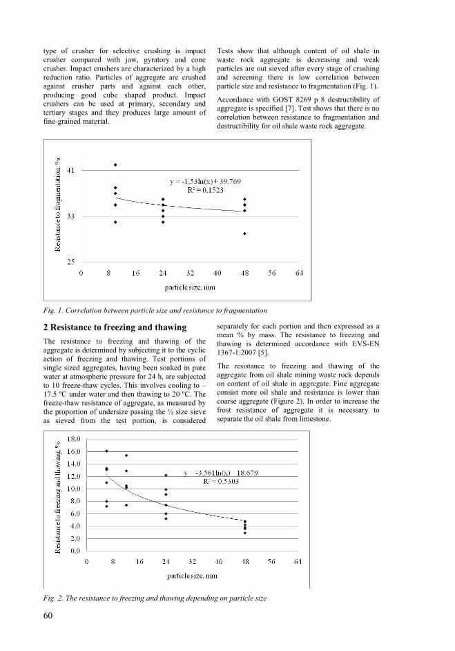
60
type of crusher for selective crushing is impact crusher compared with jaw, gyratory and cone crusher. Impact crushers are characterized by a high reduction ratio. Particles of aggregate are crushed against crusher parts and against each other, producing good cube shaped product. Impact crushers can be used at primary, secondary and tertiary stages and they produces large amount of fine-grained material.
Tests show that although content of oil shale in waste rock aggregate is decreasing and weak particles are out sieved after every stage of crushing and screening there is low correlation between particle size and resistance to fragmentation (Fig. 1).
Accordance with GOST 8269 p 8 destructibility of aggregate is specified [7]. Test shows that there is no correlation between resistance to fragmentation and destructibility for oil shale waste rock aggregate.
Fig. 1. Correlation between particle size and resistance to fragmentation
2 Resistance to freezing and thawing
The resistance to freezing and thawing of the aggregate is determined by subjecting it to the cyclic action of freezing and thawing. Test portions of single sized aggregates, having been soaked in pure water at atmospheric pressure for 24 h, are subjected to 10 freeze-thaw cycles. This involves cooling to –17.5 ºC under water and then thawing to 20 ºC. The
freeze-thaw resistance of aggregate, as measured by the proportion of undersize passing the ½ size sieve
as sieved from the test portion, is considered
separately for each portion and then expressed as a mean % by mass. The resistance to freezing and thawing is determined accordance with EVS-EN 1367-1:2007 [5].
The resistance to freezing and thawing of the aggregate from oil shale mining waste rock depends on content of oil shale in aggregate. Fine aggregate consist more oil shale and resistance is lower than coarse aggregate (Figure 2). In order to increase the frost resistance of aggregate it is necessary to separate the oil shale from limestone.
Fig. 2. The resistance to freezing and thawing depending on particle size
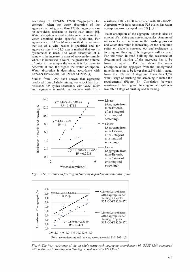
61
According to EVS-EN 12620 “Aggregates for concrete” when the water absorption of the aggregate is not greater than 1% the aggregate can be considered resistant to freeze-thaw attack [6]. Water absorption is used to determine the amount of water absorbed under specified conditions. For aggregates size 31.5 – 63 mm a method that requires the use of a wire basket is specified and for aggregate size 4 – 31.5 mm a method that uses a pyknometer is used. The water absorption of a sample is the increase in mass of an oven dry sample when it is immersed in water, the greater the volume of voids in the sample the easier it is for water to penetrate it and the higher the water absorption. Water absorption is determined accordance with EVS-EN 1097-6:2000+AC:2002+A1:2005 [4].
Studies from 1990 have shown that aggregate produced from oil shale mining waste rock has frost resistance F25 cycles accordance with GOST 8269 and aggregate is usable in concrete with frost-
resistance F100 - F200 accordance with 10060.0-95. Aggregate with frost-resistance F25 cycles has water absorption lower or equal than 5% [1;2].
Water absorption of the aggregate depends also on amount of crushing and screening cycles. Amount of microcracks will increase in the crushing process and water absorption is increasing. At the same time softer oil shale is screened out and resistance to freezing and thawing of the aggregate will increase. For utilization in road building the resistance of freezing and thawing of the aggregate has to be lower or equal to 4%. Test shows that water absorption of the aggregate from the underground mine Estonia has to be lower than 2,5% with 1 stage, lower than 3% with 2 stage and lower than 3,5% with 3 stage of crushing and screening to match the requirements (Figure 3). Correlation between resistance to freezing and thawing and absorption is low after 3 stage of crushing and screening.
y = 4,8x - 9,24R² = 1
y = 3,8293x - 8,0673R² = 0,4714
y = 1,5889x - 3,7656R² = 0,2238
0,0
2,0
4,0
6,0
8,0
10,0
12,0
14,0
2 4 6
Res
ista
nce
to fr
eezi
nf a
nd
thaw
ing,
%
Water absorption, %
Linear (Aggregate from mine Estonia, after 1 stage of crushing and screening)
Linear (Aggregate from mine Estonia, after 2 stage of crushing and screening)
Linear (Aggregate from mine Estonia, after 3 stage of crushing and screening)
Fig. 3. The resistance to freezing and thawing depending on water absorption
y = 0,7175x + 5,8452R² = 0,5506
y = 0,6793x + 2,5369R² = 0,7479
0,0
2,0
4,0
6,0
8,0
10,0
12,0
14,0
16,0
18,0
0,0 2,0 4,0 6,0 8,0 10,012,014,0
Los
s of
mas
s of
the
aggr
egat
e, %
Resistance to freezing and thawing accordance with EN 1367-1, %
Linear (Loss of mass of the aggregate after freezing 25 cycles, F25 (GOST 8269-87))
Linear (Loss of mass of the aggregate after freezing 15 cycles, F15 (GOST 8269-87))
Fig. 4. The frost-resistance of the oil shale waste rock aggregate accordance with GOST 8269 compared with resistance to freezing and thawing accordance with EN 1367-1
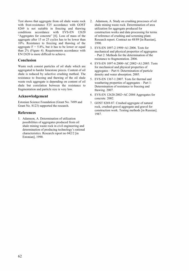
62
Test shows that aggregate from oil shale waste rock with frost-resistance F25 accordance with GOST 8269 is not suitable in freezing and thawing conditions accordance with EVS-EN 12620 “Aggregates for concrete” [6]. Loss of mass of the aggregate after 15 or 25 cycles has to be lower than 10%. Resistance to freezing and thawing of the aggregate F = 5.8%, but it has to be lower or equal than 2% (Figure 4). Requirements accordance with EN12620 is more difficult to achieve.
Conclusion
Waste rock consist particles of oil shale which are aggregated to harder limestone pieces. Content of oil shale is reduced by selective crushing method. The resistance to freezing and thawing of the oil shale waste rock aggregate is depending on content of oil shale but correlation between the resistance to fragmentation and particle size is very low.
Acknowledgement
Estonian Science Foundation (Grant No. 7499 and Grant No. 8123) supported the research.
References
1. Adamson, A. Determination of utilization possibilities of aggregates produced from oil shale mining waste rock in civil engineering and determination of producing technology’s rational
characteristics. Research report no 042/2 [in Estonian], 1990.
2. Adamson, A. Study on crushing processes of oil shale mining waste rock. Determination of area utilization for aggregate produced for construction works and data processing for terms of reference of crushing and screening plant. Research report. Contract no 48/89 [in Russian], 1990.
3. EVS-EN 1097-2:1998+A1:2006. Tests for mechanical and physical properties of aggregates – Part 2: Methods for the determination of the resistance to fragmentation. 2006.
4. EVS-EN 1097-6:2000+AC:2002+A1:2005. Tests for mechanical and physical properties of aggregates – Part 6: Determination of particle density and water absorption. 2005.
5. EVS-EN 1367-1:2007. Tests for thermal and weathering properties of aggregates – Part 1: Determination of resistance to freezing and thawing. 2007.
6. EVS-EN 12620:2002+AC:2004 Aggregates for concrete. 2002.
7. GOST 8269-87. Crushed aggregate of natural rock, crushed-gravel aggregate and gravel for construction work. Testing methods [in Russian]. 1987.

109
PAPER VII. Tohver, T.; 2010. Utilization of waste rock from oil shale mining. Oil
Shale, 2010, Vol. 27 (4), pp. 321–330. 2010.

Oil Shale, 2010, Vol. 27, No. 4, pp. 321–330 ISSN 0208-189X
doi: 10.3176/oil.2010.4.05 © 2010 Estonian Academy Publishers
UTILIZATION OF WASTE ROCK FROM OIL SHALE
MINING
T. TOHVER*
Eesti Energia Kaevandused Ltd
41533 Jõhvi, 10 Jaama Str. Estonia
The paper deals with utilization of oil shale mining waste rock in Estonia.
Crushed waste rock is utilized as an aggregate in civil engineering in frost-
free environmental conditions and in road building in unbound mixtures where required resistance to fragmentation LA 35%. This study determines
areas of utilization of waste rock and shows that waste rock aggregate
produced using selective mining or selective crushing technology is usable in civil engineering in partially saturated conditions and in unbound mixtures
where aggregates require resistance to fragmentation LA 30%. Waste rock
is usable for backfilling the already mined areas.
Introduction
The Estonia oil shale deposit stretches from the Russian border at the Narva
River 130 km west along the Gulf of Finland. Oil shale is a yellowish-
brown, relatively soft sedimentary rock of low density that contains a
significant amount of organic matter and carbonate fossils. The productive
oil shale stratum contains oil shale (layers A, B, C, D, E, F1), limestone
layers (A/B, B/C, C/D, D/E, E/F1) and limestone concretions (Fig. 1). The
thickness of the oil shale seam, without partings, ranges between 1.7 m and
2.3 m. The compressive strength of oil shale is 15 MPa to 40 MPa compared
to 40 MPa to 80 MPa for limestone. The density of oil shale is between 1400
kg/m3 and 1800 kg/m3, and that of limestone is between 2200 kg/m3 and
2600 kg/m3 [1].
Annually circa 15 million tonnes of oil shale are extracted, 50% is mined
in underground mines and 50% in surface mines. Oil shale waste rock
(limestone, marlstone or dolostone) is produced during extraction as reject
material from separation plant and material from crushing and sizing
operations in aggregate production. Major part of waste rock from opencast
mine is used for mining site restoration. Waste rock from underground mine
* Corresponding author: e-mail [email protected]
T. Tohver
322
is piled up in waste rock dumps near to mines, and the deposited amount is
about 5 million tonnes per year. In some cases dumps have been designed
for recreational purposes. The total amount of already deposited waste rock
is over 100 million tonnes. Crushed waste rock from separation plant pro-
duced in classes 25/100 and 100/300 mm [2] is utilized as a fill soil and for
construction of embankment in road building. Aggregate produced from
waste rock is utilized in road building and in civil engineering.
Extraction taxes for mining right and discharge of waste in Estonia are
continually increasing. Charge for the extraction of low-quality limestone
belonging to the state in 2006 was 0.45 € per m3, but in 2015 it will be 1.25 €
per m3 [3], and charge rate for oil shale waste rock disposal in 2006 was 0.38 €
per tonne, but in 2011 it will be 0.76 € per tonne [4]. So there is demand to
exploit natural resources of construction materials in more rational ways and
to utilize already mined and deposited waste rock in economic activities.
Worldwide experience shows that solid waste including mineral proces-
sing waste and quarry by-products can be utilized for different purposes, also
in civil engineering and road building [5–7].
Waste rock utilization in Estonia has started in 1957 when the base for
the road between the towns of Jõhvi and Kohtla-Järve was build using the
rock from underground mine Kukruse. Studies on utilization of aggregate
produced from the oil shale mining waste rock started in 1989 under
direction of Prof. Emer. Alo Adamson. For aggregate producing there were
used waste rock from different separation technologies and from seam E/C
(Fig. 1) from opencasts Aidu and Narva. The conclusion was made that it is
possible to use the aggregate in road building for base construction where
traffic volume is low and in concrete with compressive strength M300 in
accordance with GOST 10268 and with frost resistance F100-F200 in
accordance with GOST 10060 [8]. The first crushing and screening plant
equipped with two-stage impact crushers was installed in opencast Aidu [9].
In 2001/02 aggregate was produced from waste rock from underground mine
Estonia and opencast Aidu at this plant. The tests showed that aggregate
from waste rock has resistance to fragmentation LA = 30–35% and resistance
to freezing and thawing F = 4–14%. The conclusion was made that in order
to increase the resistance of aggregate a third impact crusher should be
installed to crush additionally 20-mm particles retained on screen. In 2006, a
three stage crushing plant with impact crushers was installed in opencast
Aidu (Fig. 2). In 2009 about 1 million tonnes of waste rock and 0.3 million
tonnes of waste rock aggregate were utilized in road building. Aggregate
produced in natural limestone quarries in Estonia can have resistance to
fragmentation LA = 20–30% and resistance to freezing and thawing 1–2%
and is used in road constructions where traffic volume is high [10] and in civil
engineering in partially saturated conditions [11]. Waste rock aggregates have
usually resistance to fragmentation LA 30% and resistance to freezing and
thawing F 2%, and therefore can be utilized in road building where traffic
volume is low and in concrete in frost free conditions.
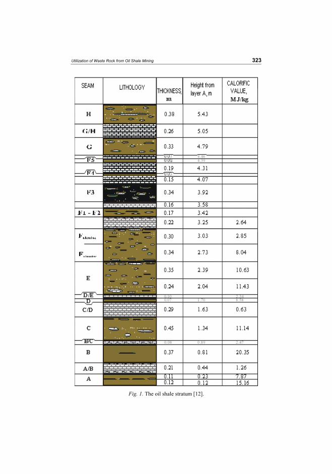
Utilization of Waste Rock from Oil Shale Mining
323
Fig. 1. The oil shale stratum [12].
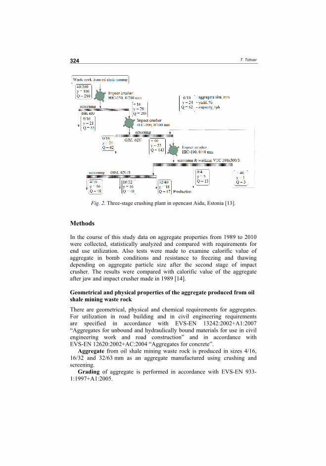
T. Tohver
324
Fig. 2. Three-stage crushing plant in opencast Aidu, Estonia [13].
Methods
In the course of this study data on aggregate properties from 1989 to 2010
were collected, statistically analyzed and compared with requirements for
end use utilization. Also tests were made to examine calorific value of
aggregate in bomb conditions and resistance to freezing and thawing
depending on aggregate particle size after the second stage of impact
crusher. The results were compared with calorific value of the aggregate
after jaw and impact crusher made in 1989 [14].
Geometrical and physical properties of the aggregate produced from oil
shale mining waste rock
There are geometrical, physical and chemical requirements for aggregates.
For utilization in road building and in civil engineering requirements
are specified in accordance with EVS-EN 13242:2002+A1:2007
“Aggregates for unbound and hydraulically bound materials for use in civil
engineering work and road construction” and in accordance with
EVS-EN 12620:2002+AC:2004 “Aggregates for concrete”.
Aggregate from oil shale mining waste rock is produced in sizes 4/16,
16/32 and 32/63 mm as an aggregate manufactured using crushing and
screening.
Grading of aggregate is performed in accordance with EVS-EN 933-
1:1997+A1:2005.
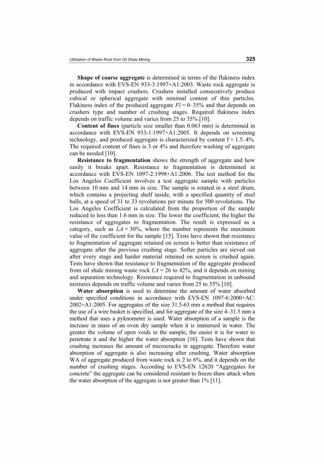
Utilization of Waste Rock from Oil Shale Mining
325
Shape of coarse aggregate is determined in terms of the flakiness index
in accordance with EVS-EN 933-3:1997+A1:2003. Waste rock aggregate is
produced with impact crushers. Crushers installed consecutively produce
cubical or spherical aggregate with minimal content of thin particles.
Flakiness index of the produced aggregate Fl = 0–35% and that depends on
crushers type and number of crushing stages. Required flakiness index
depends on traffic volume and varies from 25 to 35% [10].
Content of fines (particle size smaller than 0.063 mm) is determined in
accordance with EVS-EN 933-1:1997+A1:2005. It depends on screening
technology, and produced aggregate is characterized by content f = 1.5–4%.
The required content of fines is 3 or 4% and therefore washing of aggregate
can be needed [10].
Resistance to fragmentation shows the strength of aggregate and how
easily it breaks apart. Resistance to fragmentation is determined in
accordance with EVS-EN 1097-2:1998+A1:2006. The test method for the
Los Angeles Coefficient involves a test aggregate sample with particles
between 10 mm and 14 mm in size. The sample is rotated in a steel drum,
which contains a projecting shelf inside, with a specified quantity of steel
balls, at a speed of 31 to 33 revolutions per minute for 500 revolutions. The
Los Angeles Coefficient is calculated from the proportion of the sample
reduced to less than 1.6 mm in size. The lower the coefficient, the higher the
resistance of aggregates to fragmentation. The result is expressed as a
category, such as LA = 30%, where the number represents the maximum
value of the coefficient for the sample [15]. Tests have shown that resistance
to fragmentation of aggregate retained on screen is better than resistance of
aggregate after the previous crushing stage. Softer particles are sieved out
after every stage and harder material retained on screen is crushed again.
Tests have shown that resistance to fragmentation of the aggregate produced
from oil shale mining waste rock LA = 26 to 42%, and it depends on mining
and separation technology. Resistance required to fragmentation in unbound
mixtures depends on traffic volume and varies from 25 to 35% [10].
Water absorption is used to determine the amount of water absorbed
under specified conditions in accordance with EVS-EN 1097-6:2000+AC:
2002+A1:2005. For aggregates of the size 31.5-63 mm a method that requires
the use of a wire basket is specified, and for aggregate of the size 4–31.5 mm a
method that uses a pyknometer is used. Water absorption of a sample is the
increase in mass of an oven dry sample when it is immersed in water. The
greater the volume of open voids in the sample, the easier it is for water to
penetrate it and the higher the water absorption [16]. Tests have shown that
crushing increases the amount of microcracks in aggregate. Therefore water
absorption of aggregate is also increasing after crushing. Water absorption
WA of aggregate produced from waste rock is 2 to 6%, and it depends on the
number of crushing stages. According to EVS-EN 12620 “Aggregates for
concrete” the aggregate can be considered resistant to freeze-thaw attack when
the water absorption of the aggregate is not greater than 1% [11].
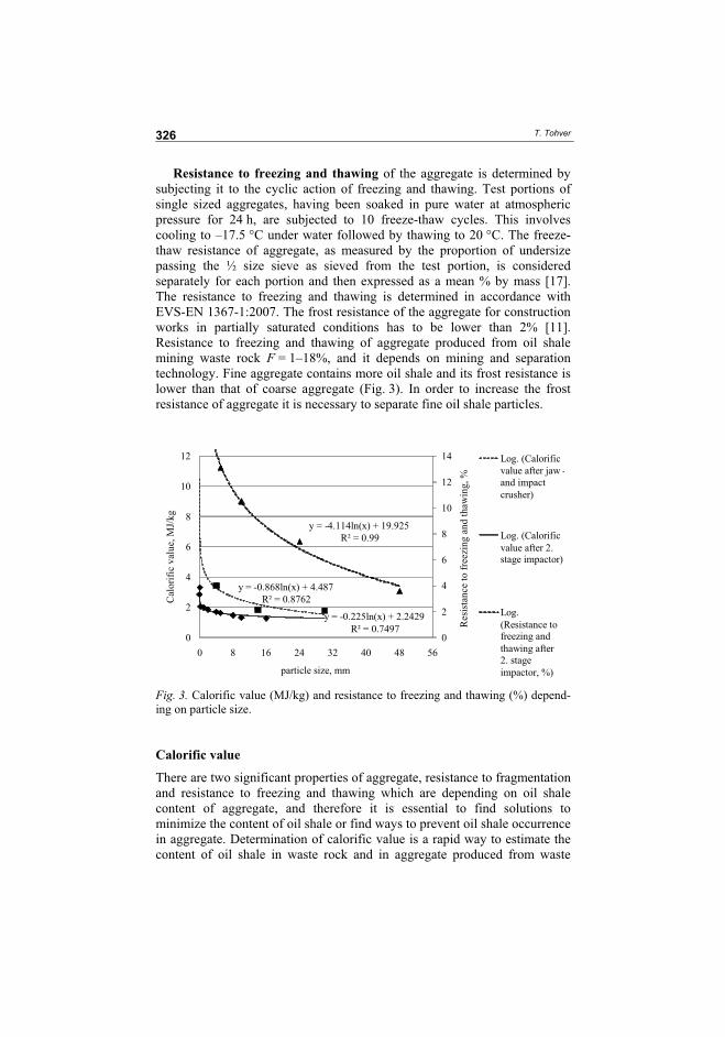
T. Tohver
326
Resistance to freezing and thawing of the aggregate is determined by
subjecting it to the cyclic action of freezing and thawing. Test portions of
single sized aggregates, having been soaked in pure water at atmospheric
pressure for 24 h, are subjected to 10 freeze-thaw cycles. This involves
cooling to –17.5 °C under water followed by thawing to 20 °C. The freeze-
thaw resistance of aggregate, as measured by the proportion of undersize
passing the ½ size sieve as sieved from the test portion, is considered
separately for each portion and then expressed as a mean % by mass [17].
The resistance to freezing and thawing is determined in accordance with
EVS-EN 1367-1:2007. The frost resistance of the aggregate for construction
works in partially saturated conditions has to be lower than 2% [11].
Resistance to freezing and thawing of aggregate produced from oil shale
mining waste rock F = 1–18%, and it depends on mining and separation
technology. Fine aggregate contains more oil shale and its frost resistance is
lower than that of coarse aggregate (Fig. 3). In order to increase the frost
resistance of aggregate it is necessary to separate fine oil shale particles.
y = - 0.868ln(x) + 4.487
R² = 0.8762
y = -0.225ln(x) + 2.2429
R² = 0.7497
y = -4.114ln(x) + 19.925
R² = 0.99
0
2
4
6
8
10
12
14
0
2
4
6
8
10
12
0 8 16 24 32 40 48 56
particle size, mm
Log. (Calorific value after jaw -and impact crusher)
Log. (Calorific value after 2. stage impactor)
Log. (Resistance to freezing and thawing after 2. stage impactor, %)
Cal
ori
fic
val
ue,
MJ/
kg
Res
ista
nce
to
fre
ezin
g a
nd
th
awin
g,
%
Fig. 3. Calorific value (MJ/kg) and resistance to freezing and thawing (%) depend-
ing on particle size.
Calorific value
There are two significant properties of aggregate, resistance to fragmentation
and resistance to freezing and thawing which are depending on oil shale
content of aggregate, and therefore it is essential to find solutions to
minimize the content of oil shale or find ways to prevent oil shale occurrence
in aggregate. Determination of calorific value is a rapid way to estimate the
content of oil shale in waste rock and in aggregate produced from waste
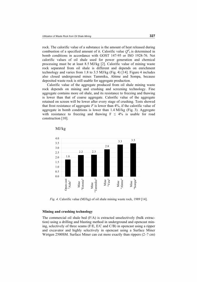
Utilization of Waste Rock from Oil Shale Mining
327
rock. The calorific value of a substance is the amount of heat released during
combustion of a specified amount of it. Calorific value Qdb is determined in
bomb conditions in accordance with GOST 147-95 or ISO 1928-76. Net
calorific values of oil shale used for power generation and chemical
processing must be at least 8.5 MJ/kg [2]. Calorific value of mining waste
rock separated from oil shale is different and depends on enrichment
technology and varies from 1.8 to 3.5 MJ/kg (Fig. 4) [14]. Figure 4 includes
also closed underground mines Tammiku, Ahtme and Sompa, because
deposited waste rock is still usable for aggregate production.
Calorific value of the aggregate produced from oil shale mining waste
rock depends on mining and crushing and screening technology. Fine
aggregate contains more oil shale, and its resistance to freezing and thawing
is lower than that of coarse aggregate. Calorific value of the aggregate
retained on screen will be lower after every stage of crushing. Tests showed
that frost resistance of aggregate F is lower than 4%, if the calorific value of
aggregate in bomb conditions is lower than 1.4 MJ/kg (Fig. 3). Aggregate
with resistance to freezing and thawing F 4% is usable for road
construction [10].
MJ/kg
1.8
2.2 2.3
2.8
3.3 3.5
0.0
0.5
1.0
1.5
2.0
2.5
3.0
3.5
4.0
Op
en-c
ast
"Aid
u"
Min
e
"Est
on
ia"
Min
e
"Tam
mik
u"
Min
e
"Vir
u"
Min
e
"Ah
tme"
Min
e
"So
mp
a"
Fig. 4. Calorific value (MJ/kg) of oil shale mining waste rock, 1989 [14].
Mining and crushing technology
The commercial oil shale bed (F/A) is extracted unselectively (bulk extrac-
tion) using a drilling and blasting method in underground and opencast min-
ing, selectively of three seams (F/E, E/C and C/B) in opencast using a ripper
and excavator and highly selectively in opencast using a Surface Miner
Wirtgen 2500SM. Surface Miner can cut more exactly than rippers (2–7 cm)
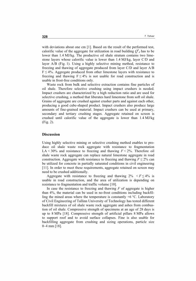
T. Tohver
328
with deviations about one cm [1]. Based on the result of the performed test,
calorific value of the aggregate for utilization in road building Qbd has to be
lower than 1.4 MJ/kg. The productive oil shale stratum contains two lime-
stone layers whose calorific value is lower than 1.4 MJ/kg, layer C/D and
layer A/B (Fig. 1). Using a highly selective mining method, resistance to
freezing and thawing of aggregate produced from layer C/D and layer A/B
F 4%. Aggregate produced from other limestone layers with resistance to
freezing and thawing F 4% is not usable for road construction and is
usable in frost-free conditions only.
Waste rock from bulk and selective extraction contains fine particles of
oil shale. Therefore selective crushing using impact crushers is needed.
Impact crushers are characterized by a high reduction ratio and are used for
selective crushing, a method that liberates hard limestone from soft oil shale.
Grains of aggregate are crushed against crusher parts and against each other,
producing a good cube-shaped product. Impact crushers also produce large
amounts of fine-grained material. Impact crushers can be used at primary,
secondary and tertiary crushing stages. Aggregate retained on screen is
crushed until calorific value of the aggregate is lower than 1.4 MJ/kg
(Fig. 2).
Discussion
Using highly selective mining or selective crushing method enables to pro-
duce oil shale waste rock aggregate with resistance to fragmentation
LA < 30% and resistance to freezing and thawing F < 2%. Therefore oil
shale waste rock aggregate can replace natural limestone aggregate in road
construction. Aggregate with resistance to freezing and thawing F 2% can
be utilized for concrete in partially saturated conditions in civil engineering
[11]. In order to meet these requirements, aggregate retained on screen may
need to be crushed additionally.
Aggregate with resistance to freezing and thawing 2% < F 4% is
usable in road construction, and the area of utilization is depending on
resistance to fragmentation and traffic volume [10].
In case the resistance to freezing and thawing F of aggregate is higher
than 4%, the material can be used in no-frost conditions including backfil-
ling the mined areas where the temperature is constantly +6 °C. Laboratory
of Civil Engineering of Tallinn University of Technology has tested different
backfill mixtures of oil shale waste rock aggregate and ashes from combus-
tion of oil shale. Compressive strength of specimens at an age of 28 days is
up to 8 MPa [18]. Compressive strength of artificial pillars 8 MPa allows
to support roof and to avoid surface collapses. Fine is also usable for
backfilling aggregate from crushing and sizing operations, particle size
0–4 mm [18].
Utilization of Waste Rock from Oil Shale Mining
329
The use of oil shale ash and oil shale mining waste rock as backfilling
materials decreases the amount of wastes dangerous to the environment. The
effects of backfilling are significant: minimization of surface movement
above underground mines, improvement of safety, facilitation of mining
operations, and increase of extraction ratio. From the other side, backfilling
has been considered an inevitable part of mining technology. For working
out new technologies for Estonian oil shale mines it is necessary to perform
supplementary investigation on backfilling in underground conditions.
Underground utilization of oil shale combustion and oil shale mining waste
rock reduces the volume and area required for surface disposal.
Conclusions
As a result of this study, the areas of utilization of oil shale waste rock are
determined. Waste rock is usable for road construction and in civil engineer-
ing under certain circumstances and areas depending on aggregate calorific
value, on resistance to freezing and thawing and on resistance to fragmenta-
tion. In case the aggregate frost resistance is low (F 4%), aggregate is
usable for backfilling the mined areas. Selective mining or selective crushing
method guarantee required properties of aggregate.
Acknowledgement
This research was supported by Estonian Science Foundation (Grant
No. 7499).
REFERENCES
1. Lohk, M., Väli, E., Tohver, T., Pastarus, J.-R. Surface miner technology impact
on the environment // 5th International Symposium “Topical problems in the
field of electrical and power engineering”. Doctoral school of energy and
geotechnology / Lahtmets, R. (Ed). Tallinn University of Technology. 2008.
P. 44–47.
2. Väli, E., Valgma, I., Reinsalu, E. Usage of Estonian oil shale // Oil Shale. 2008.
Vol. 25, No. 2S. P. 101–114.
3. Regulation of the Estonian Government, 2005. The rates of the mineral
resources extraction charge for the extraction of mineral resources belonging to
the state for 2006–2009. RTI 2005, 71, 553 [in Estonian].
4. Environmental Charges Act. RTI 2005, 67, 512 [in Estonian].
5. Collins, R. J., Miller, R. H. Utilization of mining and mineral processing wastes
in the United States // Environ. Geochem. Hlth. 1979. Vol. 1, No. 1. P. 8–19.
T. Tohver
330
6. Kassim, T. A., Simoneit, B. R., Williamson, K. J. Recycling Solid Wastes as
Road Construction Materials: An Environmentally Sustainable Approach. –
Handb. Environ. Chem. 2005. Vol. 5, Part F, Vol. 1. P. 59–181.
7. Rai, M. Mining & Mineral Wastes for the Development of Building Materials.
www.ics.trieste.it/media/135657/df3730.pdf.
8. Adamson, A. Study on crushing processes of oil shale mining waste rock.
Determination of utilization area of the produced aggregate for construction
works and data processing for terms of reference of crushing and screening
plant. Research report. Contract no 48/89, 1990 [in Russian].
9. Yurkevich, G. Researching of industrial wastes, composition and industrial
testing of building mixtures recipes for the underground mining. Research
report. Study no 508L, 1995 [in Russian].
10. Estonian Asphalt Pavement Association. Asphalt Norms AL-ST 1-02. 2002 [in
Estonian].
11. EVS-EN 12620:2002+AC:2004 Aggregates for concrete. 2004.
12. Eesti Energia Kaevandused Ltd. Mine layout of Estonian oil shale deposit
(unpubl. manuscript), 2009 [in Estonian].
13. Eesti Energia Kaevandused Ltd. Three stage crushing plant in open cast Aidu
(unpubl. manuscript), 2006 [in Russian].
14. Adamson, A. Study on utilization possibilities of the aggregate produced from
oil shale mining waste products. Research report no 955, 1989 [in Estonian].
15. EVS-EN 1097-2:1998+A1:2006. Tests for mechanical and physical properties
of aggregates – Part 2: Methods for the determination of the resistance to
fragmentation. 2006.
16. EVS-EN 1097-6:2000+AC:2002+A1:2005. Tests for mechanical and physical
properties of aggregates – Part 6: Determination of particle density and water
absorption. 2005.
17. EVS-EN 1367-1:2007. Tests for thermal and weathering properties of
aggregates – Part 1: Determination of resistance to freezing and thawing. 2007.
18. Raado, L.-M. Waste rock from oil shale mining and separation for backfilling
mined areas. Tallinn University of Technology Department of Building Pro-
duction Research and Testing Laboratory of Building Materials. Research
report. Contract no 8008 (unpubl. manuscript), 2008 [in Estonian].
Presented by V. Kalm
Received March 18, 2010
121
DISSERTATIONS DEFENDED AT
TALLINN UNIVERSITY OF TECHNOLOGY ON
POWER ENGINEERING, ELECTRICAL ENGINEERING,
MINING ENGINEERING
1. Jaan Tehver. Boiling on porous surface. 1992.
3. Endel Risthein. Electricity supply of industrial plants. 1993.
4. Tõnu Trump. Some new aspects of digital filtering. 1993.
5. Vello Sarv. Synthesis and design of power converters with reduced distortions using optimal energy exchange control. 1994.
6. Ivan Klevtsov. Strained condition diagnosis and fatigue life prediction for metals under cyclic temperature oscillations. 1994.
7. Ants Meister. Some phase-sensitive and spectral methods in biomedical engineering. 1994.
8. Mati Meldorf. Steady-state monitoring of power system. 1995.
9. Jüri-Rivaldo Pastarus. Large cavern stability in the Maardu granite deposit. 1996.
10. Enn Velmre. Modeling and simulation of bipolar semiconductor devices. 1996.
11. Kalju Meigas. Coherent photodetection with a laser. 1997.
12. Andres Udal. Development of numerical semiconductor device models and their application in device theory and design. 1998.
13. Kuno Janson. Paralleel- ja järjestikresonantsi parameetrilise vaheldumisega
võrgusageduslik resonantsmuundur ja tema rakendamine. 2001.
14. Jüri Joller. Research and development of energy saving traction drives for trams. 2001.
15. Ingo Valgma. Geographical information system for oil shale mining – MGIS. 2002.
16. Raik Jansikene. Research, design and application of magnetohydrodynamical (MHD) devices for automation of casting industry. 2003.
17. Oleg Nikitin. Optimization of the room-and-pillar mining technology for oil-shale mines. 2003.
18. Viktor Bolgov. Load current stabilization and suppression of flicker in AC arc furnace power supply by series-connected saturable reactor. 2004.
122
19. Raine Pajo. Power system stability monitoring – an approach of electrical load modelling. 2004.
20. Jelena Shuvalova. Optimal approximation of input-output characteristics of power units and plants. 2004.
21. Nikolai Dorovatovski. Thermographic diagnostics of electrical equipment of Eesti Energia Ltd. 2004.
22. Katrin Erg. Groundwater sulphate content changes in Estonian underground oil shale mines. 2005.
23. Argo Rosin. Control, supervision and operation diagnostics of light rail electric transport. 2005.
24. Dmitri Vinnikov. Research, design and implementation of auxiliary power supplies for the light rail vehicles. 2005.
25. Madis Lehtla. Microprocessor control systems of light rail vehicle traction drives. 2006.
26. Jevgeni Šklovski. LC circuit with parallel and series resonance alternation in switch-mode converters. 2007.
27. Sten Suuroja. Comparative morphological analysis of the early paleozoic marine impact structures Kärdla and Neugrund, Estonia. 2007.
28. Sergei Sabanov. Risk assessment methods in Estonian oil shale mining industry. 2008.
29. Vitali Boiko. Development and research of the traction asynchronous multimotor drive. 2008.
30. Tauno Tammeoja. Economic model of oil shale flows and cost. 2008.
31. Jelena Armas. Quality criterion of road lighting measurement and exploring. 2008.
32. Olavi Tammemäe. Basics for geotechnical engineering explorations considering needed legal changes. 2008.
33. Mart Landsberg. Long-term capacity planning and feasibility of nuclear power in Estonia under certain conditions. 2008.
34. Hardi Torn. Engineering-geological modelling of the Sillamäe radioactive
tailings pond area. 2008.
35. Aleksander Kilk. Paljupooluseline püsimagnetitega sünkroongeneraator tuule-agregaatidele. 2008.
36. Olga Ruban. Analysis and development of the PLC control system with the distributed I/Os. 2008.
37. Jako Kilter. Monitoring of electrical distribution network operation. 2009.
123
38. Ivo Palu. Impact of wind parks on power system containing thermal power plants. 2009.
39. Hannes Agabus. Large-scale integration of wind energy into the power system considering the uncertainty information. 2009.
40. Kalle Kilk. Variations of power demand and wind power generation and their influence to the operation of power systems. 2009.
41. Indrek Roasto. Research and development of digital control systems and algorithms for high power, high voltage isolated DC/DC converters. 2009.
42. Hardi Hõimoja. Energiatõhususe hindamise ja energiasalvestite arvutuse
metoodika linna elektertranspordile. 2009.
43. Tanel Jalakas. Research and development of high-power high-voltage DC/dC converters. 2010.
44. Helena Lind. Groundwater flow model of the western part of the Estonian oil shale deposit. 2010.
45. Arvi Hamburg. Analysis of energy development perspectives. 2010.
46. Mall Orru. Dependence of Estonian peat deposit properties on landscape types and feeding conditions. 2010.
47. Erik Väli. Best Available Technology for the Environmentally Friendly Mining with Surface Miner. 2011.


![UNIVERSITI MALAYSIA PERLISportal.unimap.edu.my/portal/page/portal30/STD_ACA... · Pengurusan dan Penggunaan Bahan Buangan [Waste Management and Utilization] 2.30 petang (pm) 3 jam](https://img.pdfslide.tips/doc/110x75/5e46133f45d1fc74fc488e4d/universiti-malaysia-pengurusan-dan-penggunaan-bahan-buangan-waste-management-and.jpg)