Embed Size (px)
Citation preview

BON-6002
V-Cut solder machine
Solder diameter φ0.6~φ1.6
Instruction manual (User’s Manual)
Preparation in April 2014
The 6nd edition
JAPAN BONKOTE CO.,LTD.
V-Solder
®

1

1
Contents
1 Preface ・・・・・・・・・・・・・・・・・・・・・・・・・・・・・・・・・・・・・・・・ 1
2 Notes for safety ・・・・・・・・・・・・・・・・・・・・・・・・・・・・・・・・・・・・ 1
3 Notes for installation and use・・・・・・・・・・・・・・・・・・・・・・・・・・・・・・・ 2
4 How to use V-Solder machine
(A) Contents・・・・・・・・・・・・・・・・・・・・・・・・・・・・・・・・・・・・・・ 3
(B) Name of body parts・・・・・・・・・・・・・・・・・・・・・・・・・・・・・・・・・ 4
(C) How to set up・・・・・・・・・・・・・・・・・・・・・・・・・・・・・・・・・・・・5
(D) How to use・・・・・・・・・・・・・・・・・・・・・・・・・・・・・・・・・・・・・6
5 How to maintenance
(A) Depth of V-groove and the Adjustment
(1) Depth of V-groove・・・・・・・・・・・・・・・・・・・・・・・・・・・・・・・7
(2) Adjustment・・・・・・・・・・・・・・・・・・・・・・・・・・・・・・・・・・8
(B) Replacement of parts
(1) V-blade ・・・・・・・・・・・・・・・・・・・・・・・・・・・・・・・・・・・9
(2) Guide pulley・・・・・・・・・・・・・・・・・・・・・・・・・・・・・・・・・10
(3) Extracting needle・・・・・・・・・・・・・・・・・・・・・・・・・・・・・・・11
(4) Solder guide・・・・・・・・・・・・・・・・・・・・・・・・・・・・・・・・・12
(5) Fuse・・・・・・・・・・・・・・・・・・・・・・・・・・・・・・・・・・・・ 12
6 Consumption parts
(A) Guide pulley & V-blade・・・・・・・・・・・・・・・・・・・・・・・・・・・・・・・ 13
(B) Extracting needle・・・・・・・・・・・・・・・・・・・・・・・・・・・・・・・・・・13
(C) Solder guide・・・・・・・・・・・・・・・・・・・・・・・・・・・・・・・・・・・・13
(D) Fuse・・・・・・・・・・・・・・・・・・・・・・・・・・・・・・・・・・・・・・・13
7 Specifications
(A) BON-6002・・・・・・・・・・・・・・・・・・・・・・・・・・・・・・・・・・・・・14
8 Question & Answer
(A) Trouble shooting・・・・・・・・・・・・・・・・・・・・・・・・・・・・・・・・・・15
9 Guarantee and After service
(A) Guarantee・・・・・・・・・・・・・・・・・・・・・・・・・・・・・・・・・・・・・ 16
(B) After service・・・・・・・・・・・・・・・・・・・・・・・・・・・・・・・・・・・・16

1
1. Preface
Thank you very much for purchasing V-Solder.
V-Solder is effective to prevent solder ball & flux scattering, with
making V groove onto solder wire.
Please read through this instruction manual before use, and use
BON-6002/6130 properly.
Also keep this manual after read.
2. Notes for safety
Be sure to read this manual before using this machine.
Never touch the power cable and 3P &2P core pin of machine with dump hands.
Otherwise, you may get hurt due to electric shock and etc. (death at worse)
Never dampen machine with water or liquid.
Otherwise, burst cord may cause fire, malfunction, electric shock and etc. (death at worse)
Never make the power cable and 3P &2P core pin of machine close to heat source.
Otherwise burnt cord may cause fire, malfunction, electric shock and etc.
Do not overhaul the machine when the machine has trouble. Otherwise, it may cause
malfunction, electric shock and etc (death at worst). Contact with our customer service
department and follow instructions to make maintenance.
Be sure to use proper replacement parts such as fuse, checking capabilities.
Otherwise, parts with wrong capacities may cause fire, malfunction and etc.
Company name and products name which is written in this manual is registered trademark for each
company.
! CAUTION!

2
3. Notes for installation and use
This machine is designed with earth specification. For safety, be sure to use an earth-quipped
receptacle. (If you do not have such receptacle, install an earth separately.)
Be sure to confirm using voltage before use.
Refrain from place where the machine would be exposed too much moisture, direct sunshine,
much dust and vibration.
Be sure to pull out the power plug, when the machine is not used.
Be sure to grab the power plug instead of cable, when inserting and pulling out the plug.
Before maintenance (replacement and cleaning of V-blade, Guide pulley, Extracting needle, etc.) be
sure to set the power switch to OFF, pull out the power plug from the receptacle.
Do not use this machine for purpose other than the original purpose.
If you use non-genuine parts, consult with our service department for safety.
Never touch the V-blade during operation. Otherwise, you may get hurt.
Be sure to use single flux solder wire. For multi flux solder wire, effect is decreased.
Be sure to make V-groove onto solder wire just before use the solder. Leaving for a while after
V-grooved, effect of V-solder and soldering quality assurance are decreased.

3
4. How to use
(A) Contents(BON-6002)
① BON-6002 body
② Foot Switch
③ Power cable 3PCHI
④ Spanner (14mm)
⑤ Reel axis
⑥ Adjuster gauge
①
② ③
④ ⑤
BON-6002
⑥

4
①
②
③ ④
⑤ ⑥
⑦
⑧
⑨
⑩
⑪
⑫
⑬
⑮ ⑭
(B) Name of body parts
《 Side 》 《 Front 》
① Upper/Lower Adjuster screw ⑨ Upper housing
② V blade ⑩ V blade axis
③ V blade holder ⑪ Gear 28
④ Spring ⑫ Gear 30
⑤ Solder guide ⑬ Guide pulley axis
⑥ Extracting needle ⑭ Lower housing
⑦ Guide pulley ⑮ Metal fittings to hold Solder guide
⑧ Guide shaft

5
(C) How to set up
① Connect power cable to V-solder
machine.
② Set solder wire reel to behind
holder. Conform diameter of solder wire and guide pulley are same.
③ The cushioning material is for
buffer solution during delivery. Please remove it before use.
Preparation before use is done.

6
(D) How to use
(1) Insert the power plug in the receptacle and switch on.
(2) Set solder wire into housing.
① Lead the solder into Solder guide.
② Insert solder wire between groove
of Guide pulley and V-blade, and send solder wire little by little with pressing foot switch.
(3) Send solder wire with pressing foot switch.
③ Press foot switch, solder wire is
V-grooved and come out with passing top of guide pulley.
7
5. How to Maintenance
(A) How to check Depth of V-groove, and the adjustment
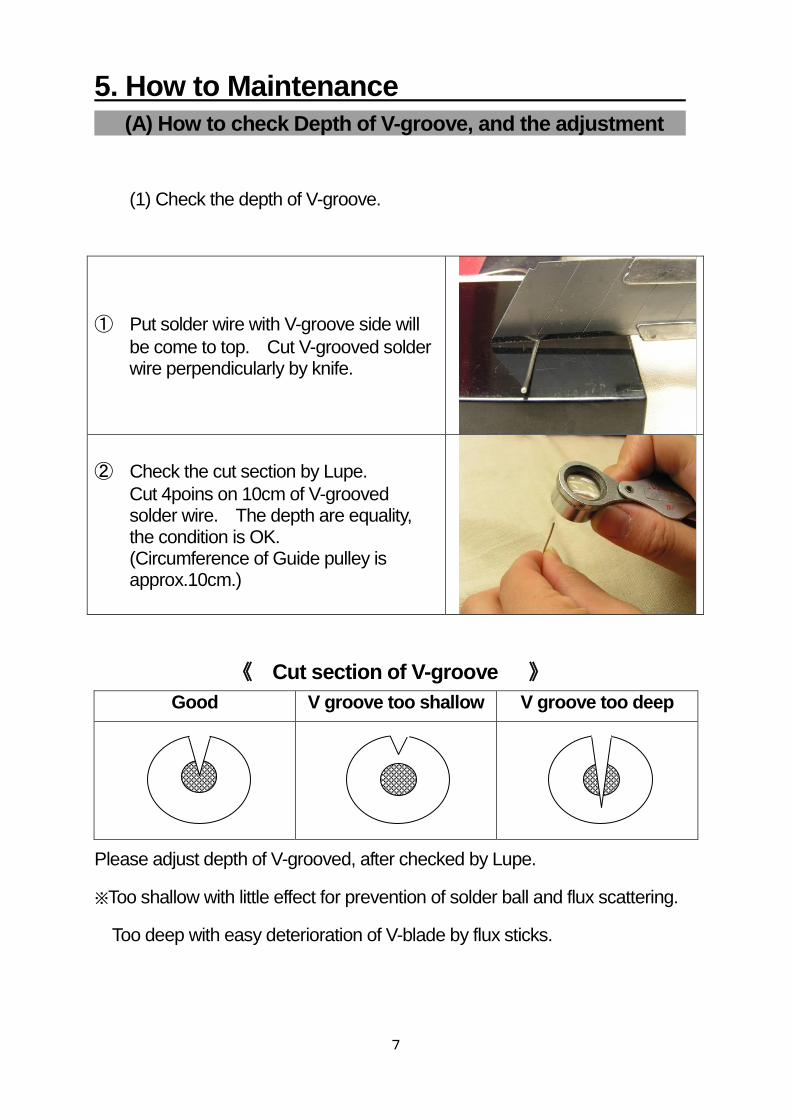
(1) Check the depth of V-groove.
① Put solder wire with V-groove side will
be come to top. Cut V-grooved solder wire perpendicularly by knife.
② Check the cut section by Lupe.
Cut 4poins on 10cm of V-grooved solder wire. The depth are equality, the condition is OK. (Circumference of Guide pulley is approx.10cm.)
《 Cut section of V-groove 》
Good V groove too shallow V groove too deep
Please adjust depth of V-grooved, after checked by Lupe.
※Too shallow with little effect for prevention of solder ball and flux scattering.
Too deep with easy deterioration of V-blade by flux sticks.

8
(2) Adjust depth
① Loosen screw of housing cover
and remove the housing cover.
② Loosen upper/lower adjuster screw
alternatively by 1 turn until there will be enough space to insert adjuster gauge. Insert adjuster gauge between upper housing and lower housing, and tighten adjuster screw alternatively by 1 turn with attached spanner (10mm) as the height will be flat.
③ Adjust height of housing by using
attached spanner (10mm).
・Lower housing for shallow V-grooved. ・Raise housing for deep V-grooved.
Tighten each adjuster screw by 1 turn
alternatively same as ②.
④ Check depth of solder at the cut side
by Lupe.
⑤ Set housing cover and tighten screw
after adjustment.

9
(B) Replacement of parts
(1) Replacement of V-blade
① Loosen screw and remove housing
cover.
② Loosen upper/lower adjuster screw
with attached spanner (10mm) alternatively by 1 turn until V-blade and Guide pulley are completely separated.
※If V-blade and guide pulley are not
completely separated, unable to take out V-blade for exchange
③ Insert attached spanner(14mm) into
V blade axis. Insert attached spanner (10mm) into V blade holder. Remove cover nut with pulling snapper (14mm) to front and pushing spanner (10mm) to behind at same time, and exchange V blade.
※Refer right picture
④ Insert attached spanner(14mm) and
(10mm) same as No.③,
Tighten cover nut with pulling snapper (10mm) to front and pushing spanner (14mm) to behind same time.
※Refer right picture
⑤ Check the depth of V-grooved solder
wire after adjust housing height with
refer Page.8 No.②~⑤.
And Set housing cover and tighten screw.

10
(2) Replacement of Guide pulley
① Loosen screw and remove housing
cover.
② Loosen upper/lower screw by
attached spanner (10mm) till V-blade and Guide pulley are completely separated.
※If V-blade and guide pulley are not
completely separated, unable to take out Guide pulley for exchange
③Remove extracting needle.
(Refer page.11 for replacement of Extracting needle)
④ Insert attached spanner(14mm) into
Guide pulley axis. Insert attached spanner (13mm) into Guide pulley holder. Remove cover nut with push each spanner to the direction of the narrow with refer the right picture, and exchange guide pulley.
⑤ Insert the attached spanner same as
No.④, and tighten the cover nut.

11
⑥ Put back Extracting needle.
(Refer page.12 for replacement of Extracting needle)
⑦ Check the depth of V-grooved solder
wire after adjuster housing height with
refer Page.8 No.②~⑤.
And Set housing cover and tighten screw.
※ Changing to other size of guide pulley, exchanging extracting needle is
necessary depending on size. Please refer P.13 and follow the
instruction.
(3) Replacement of Extracting needle
① Hold Extracting needle by screw driver.
Loosen Extracting needle by spanner (5.5mm) and remove it.
② Attach new Extracting needle.
Please make sure to insert the spring of Extracting needle into the hole of lower housing.
③ Hold the nut with holding Extracting
needle by screw driver as ①.
Please make sure the center of needle is completely placed into groove of Guide pulley.

12
(4) Replacement of Solder guide
① Loosen screw of Solder guide by
hexangular wrench, and exchange.
② Attach new Solder guide.
Insert new Solder guide into Metal fittings to hold Solder guide, and tighten by hexangular wrench. Please adjust the center between Solder guide and Guide pulley by Metal fittings to hold Solder guide.
(5) Replacement of fuse
① Loosen fuse holder by hand, and
exchange.

13
6. Consumption parts
(A) Guide pulley & V-blade
Guide pulley Model No.
Diameter of solder wire
V blade
GP-06 φ0.6
VE-1
GP-065 φ0.65
GP-08 φ0.8
GP-10 φ1.0
GP-12 φ1.2
GP-16 φ1.6
(B) Extracting needle
Model No. Diameter of solder wire
TN-05 φ0.6~φ0.8
TN-08 φ1.0/φ1.6
Please purchase with your using solder wire diameter.
Exchange Guide pulley size, also change Extracting needle with necessary.
(C) Solder guide
Model No. Corresponding solder wire diameter
HP-20 φ0.6~φ1.6
(D) Fuse
Corresponding machine
Specifications
BON-6002 Glass tube Fuse 250V 1A(φ 5.2x20mm)

14
7. Specification
(A) Specification of BON-6002
Input voltage 100V
Frequency 50/60Hz
Feeding amount
40/48mm
Feeding method
Foot switch
Solder diameter
φ0.6~φ1.2
Dimension 142Wx122Dx160H
Weight 1950g
Power consumption
Approx. 6VA
Power cable power code with 3P plug(earth s pecification)1.6m
Case material Steel: t=1.2
Fuse Glass tube fuse 250V 1A(φ5.2x20mm)

15
8. Question & Answer
(A) Trouble shooting
Phenomena Please check Measures Page.
Motor does not move
1. Switch lump is not able to be ON
①Is the Power cable inserted to the
receptacle? Insert the power plug in the receptacle
②Is the Fuse consumed? Exchange fuse to new P12
2. Switch lump is able to be ON
①Is the V-blade contacting Guide pulley? Loosen upper housing and separate V-blade and Guide pulley
P8
②Is the Foot switch inserted to machine? Insert foot switch to machine
③Is the Foot switch broken? Exchange foot switch to new
④Is the Motor broken? Please ask us for repair
Solder ball is increased
1. Is V-grooved properly done or not? V-blade is consumed, exchange V-blade to new
P9
2. Is V-grooved onto center of solder wire or not?
①Adjust housing P8
②V-blade is consumed,
exchange V-blade to new P9
③Guide pulley is consumed,
exchange Guide pulley to new P10
V-grooved solder wire is coiled around Guide pulley.
1. Is the size of Solder wire diameter and Guide pulley size same?
Exchange Guide pulley size to same size with solder wire
P10
2. Is Extracting needle size correct? Exchange Extracting needle to correct size
P11
Solder wire is buried in Guide pulley
1. Is the size of Solder wire diameter and Guide pulley same?
Exchange Guide pulley size to same size with solder wire
P10
Extracting needle is bended, or got rust.
1. Extracting needle is consumed? Exchange Extracting needle to new P11
Solder wire come off from Guide pulley groove
1. It the space of Solder guide and Guide pulley appropriate?
Adjust Solder guide and Guide pullet to appropriate.
P11
2. Guide pulley is consumed? Exchange Guide pulley to new P10

16
9. Guarantee and after service
(A) Guarantee
Our products are shipped after several factory test & inspection. But if you
find malfunctions or defects due to problem in workmanship or transportation,
please contact with your dealer or us. The guarantee period of your system
in one year after purchase, except for replacement parts like V-blade.
(B) After service
If the machine has trouble, please read guide manual once again. If the
trouble is still not solved, please contact your dealer or our service
department.

17
JAPAN BONKOTE CO., LTD.
600-14 Kasahara-Cho, Mito-City,
Ibaraki-Pref, JAPAN
Zip: 310-0852
TEL: +81 29-241-2725
FAX: +81 29-241-2726
http://bonkote.net
®