Embed Size (px)
Citation preview
VSCVLC
VSC Series/VLC SeriesNC LOOP
NC LOOP
NC LOOP
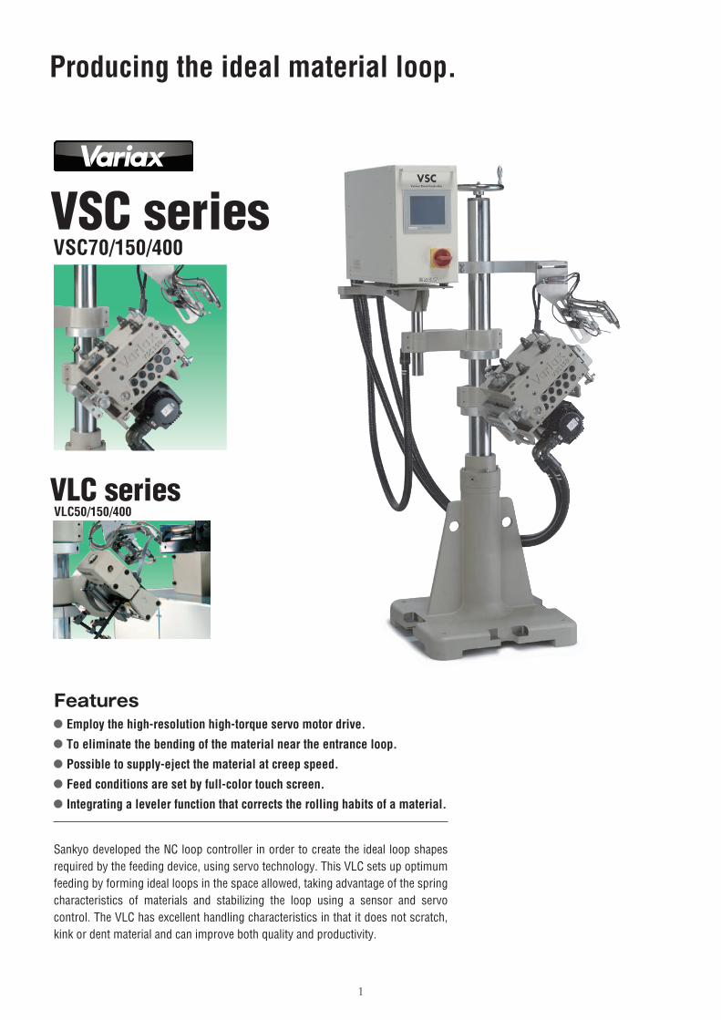
VSC seriesVSC70/150/400
VLC seriesVLC50/150/400
1
Producing the ideal material loop.
Sankyo developed the NC loop controller in order to create the ideal loop shapes required by the feeding device, using servo technology. This VLC sets up optimum feeding by forming ideal loops in the space allowed, taking advantage of the spring characteristics of materials and stabilizing the loop using a sensor and servo control. The VLC has excellent handling characteristics in that it does not scratch, kink or dent material and can improve both quality and productivity.
Features● Employ the high-resolution high-torque servo motor drive.● To eliminate the bending of the material near the entrance loop.● Possible to supply-eject the material at creep speed.● Feed conditions are set by full-color touch screen.● Integrating a leveler function that corrects the rolling habits of a material.
2
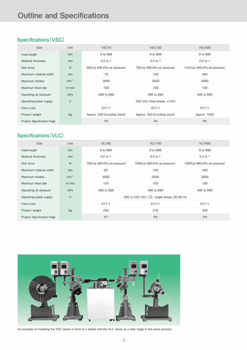
Outline and Specifications
An example of installing the VSC series in front of a feeder and the VLC series at a later stage in the press process
Specifications(VLC)VLC150Size
Feed length
Material thickness
Grip force
Maximum material width
Maximum strokes
Maximum feed rate
Operating air pressure
Operating power supply
Paint color
Product weight
Unit
mm
mm
N
mm
min-1
m/min
kPa
V
kg
VLC50 VLC400
0 to 999
0.2 to 1
0 to 999
0.2 to 1
0 to 999
0.2 to 1
350(at 490-kPa air pressure) 1500(at 490-kPa air pressure) 1500(at 490-kPa air pressure)
40050 150
30003000 3000
490 to 588 490 to 690
5Y7/15Y7/1
200 to 230 VAC , single phase, 50/60 Hz
330250 270
Product Specification Page P9P7 P8
150 100
490 to 690
5Y7/1
100
+10%-15%
Specifications(VSC)VSC150Size
Feed length
Material thickness
Grip force
Maximum material width
Maximum strokes
Maximum feed rate
Operating air pressure
Operating power supply
Paint color
Product weight
Unit
mm
mm
N
mm
min-1
m/min
kPa
V
kg
VSC70 VSC400
Approx. 330(Including stand)
5Y7/15Y7/1 5Y7/1
490 to 690
200 VAC three phase, ±10%
100
3000
490 to 690
100
3000
490 to 690
100
3000
Approx. 320(Including stand) Approx. 1000
Product Specification Page P4P3 P5
150
0 to 999
350(at 490-kPa air pressure) 700(at 490-kPa air pressure) 1470(at 490-kPa air pressure)
70
0.2 to 1
0 to 999
0.2 to 1
0 to 999
0.2 to 1
400
3
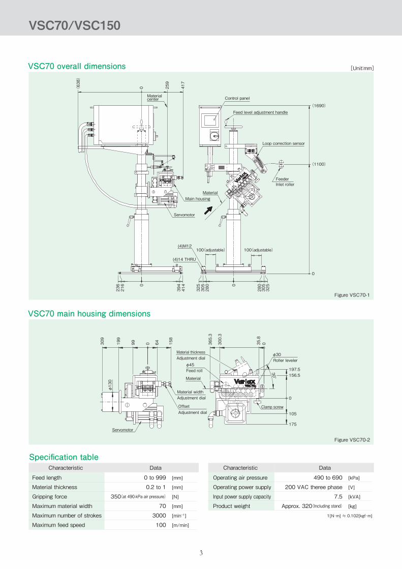
VSC70 overall dimensions
VSC70 main housing dimensions
Figure VSC70-1
Figure VSC70-2
[Unit:mm]
Loop correction sensor
MaterialMain housing
Materialcenter
Servomotor
100(adjustable)(4)M12
(4)14 THRU
100(adjustable)
Feed level adjustment handle
Control panel
(1690)
(1100)
0
236
216 0
394
414
325
305
280 0
280
305
325
(638)
0 259
417
FeederInlet roller
Material thickness
Roller leveler
Clamp screw
Adjustment dial
Feed rollφ45
φ30
30°Material
Material widthAdjustment dial
Adjustment dialOffset
Servomotor
309
199
φ130
99 0 64 158
365.3
300.3
35.8
0
197.5156.5
0
105
175
VSC70/VSC150
Specification table
[kPa]
[V]
[kVA]
[kg]
1[N・m] ≒ 0.102[kgf・m]
Feed length
Material thickness
Gripping force
Maximum material width
Maximum number of strokes
Maximum feed speed
Characteristic Data Characteristic Data
[mm]
[mm]
[N]
[mm]
[min-1]
[m/min]
0 to 999
0.2 to 1
350(at 490-kPa air pressure)
70
3000
100
490 to 690
200 VAC theree phase
7.5
Approx. 320(Including stand)
Operating air pressure
Operating power supply
Input power supply capacity
Product weight

4
VSC150 overall dimensions
VSC150 main housing dimensions
Figure VSC150-1
Figure VSC150-2
[Unit:mm]
Material widthAdjustment dial
Adjustment dialOffset Clamp screw
Roller levelerφ30
30°
197.5156.5
0
175
Material thicknessAdjustment dial
Feed rollφ45
Material
Loop correction sensor
(1690)
(1100)
0
0
236
216
394
414
325
305
280 0
280
305
325
Feed level adjustment handle
Control panelMaterialcenter
Material
Main housing
Servomotor
100(adjustable) 100(adjustable)(4)M12
(4)14 THRU
Servomotor
FeederInlet roller
(638)
0 300
500
350.5
240.5
φ130
140.5
0 105.5
199.5
365.3
300.3
35.8
0
VSC70/VSC150
Specification table
[kPa]
[V]
[kVA]
[kg]
1[N・m] ≒ 0.102[kgf・m]
Feed length
Material thickness
Gripping force
Maximum material width
Maximum number of strokes
Maximum feed speed
Characteristic Data Characteristic Data
[mm]
[mm]
[N]
[mm]
[min-1]
[m/min]
0 to 999
0.2 to 1
700(at 490-kPa air pressure)
150
3000
100
490 to 690
200 VAC theree phase
7.5
Approx. 330(Including stand)
Operating air pressure
Operating power supply
Input power supply capacity
Product weight
5
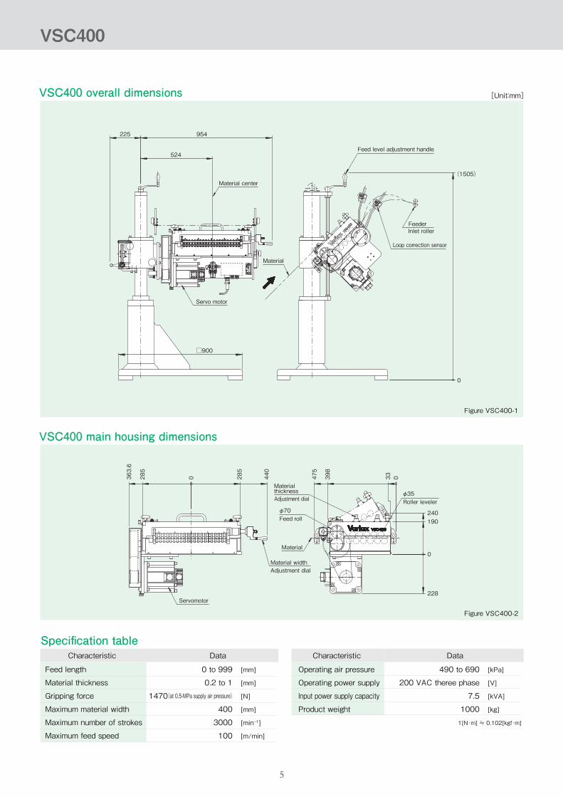
VSC400 overall dimensions
VSC400 main housing dimensions
Figure VSC400-1
Figure VSC400-2
[Unit:mm]
Material center
FeederInlet roller
Servo motor
Loop correction sensor
Feed level adjustment handle
Material
225
□900
524
954
(1505)
0
Material widthAdjustment dial
Servomotor
Material
φ35Roller leveler
φ70Feed roll
MaterialthicknessAdjustment dial
228
240190
0
475
398
33 0440
363.6
285
285
0
VSC400
Specification table
[kPa]
[V]
[kVA]
[kg]
1[N・m] ≒ 0.102[kgf・m]
Feed length
Material thickness
Gripping force
Maximum material width
Maximum number of strokes
Maximum feed speed
Characteristic Data Characteristic Data
[mm]
[mm]
[N]
[mm]
[min-1]
[m/min]
0 to 999
0.2 to 1
1470(at 0.5-MPa supply air pressure)
400
3000
100
490 to 690
200 VAC theree phase
7.5
1000
Operating air pressure
Operating power supply
Input power supply capacity
Product weight
6
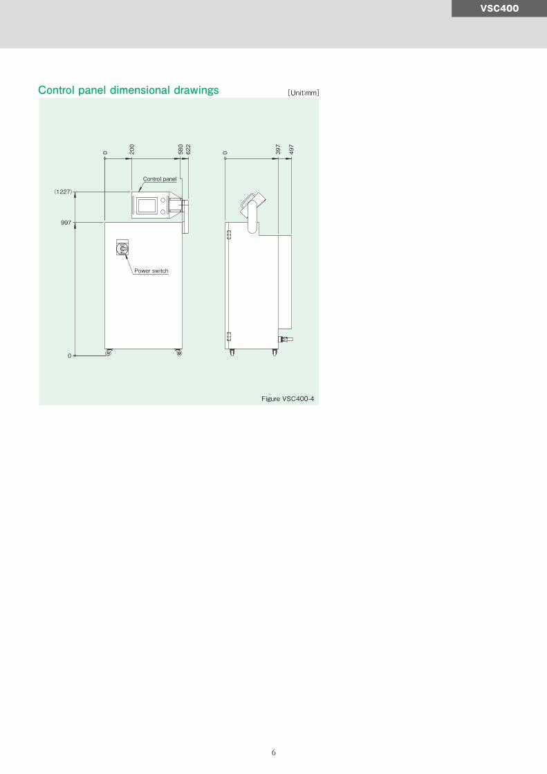
Control panel dimensional drawings
Figure VSC400-4
[Unit:mm]
Control panel
Power switch397
497
0200
622
580
0
997
(1227)
0
VSC400
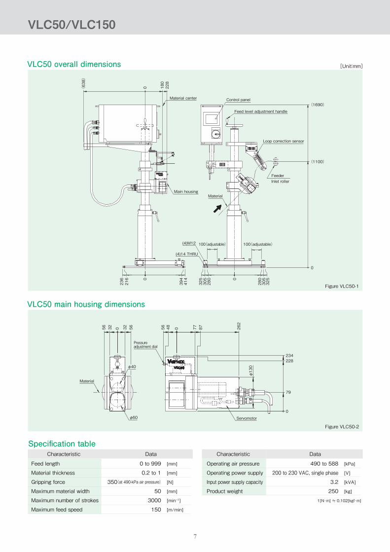
VLC50 overall dimensions
VLC50 main housing dimensions
Figure VLC50-1
Figure VLC50-2
[Unit:mm]
7
Control panel(1690)
(1100)
0
0
236
216
394
414
325
305
280 0
280
305
325
Feed level adjustment handle
Loop correction sensor
FeederInlet roller
Material center
(638)
0 180
228
MaterialMain housing
100(adjustable)(4)M12
(4)14 THRU
100(adjustable)
Pressure adjustment dial
Material
Servomotor
234228
79
0
56 56 56 48 0 77 87 262
φ130
32 320
φ40
φ60
VLC50/VLC150
Specification table
[kPa]
[V]
[kVA]
[kg]
1[N・m] ≒ 0.102[kgf・m]
Feed length
Material thickness
Gripping force
Maximum material width
Maximum number of strokes
Maximum feed speed
Characteristic Data Characteristic Data
[mm]
[mm]
[N]
[mm]
[min-1]
[m/min]
0 to 999
0.2 to 1
350(at 490-kPa air pressure)
50
3000
150
490 to 588
200 to 230 VAC, single phase
3.2
250
Operating air pressure
Operating power supply
Input power supply capacity
Product weight
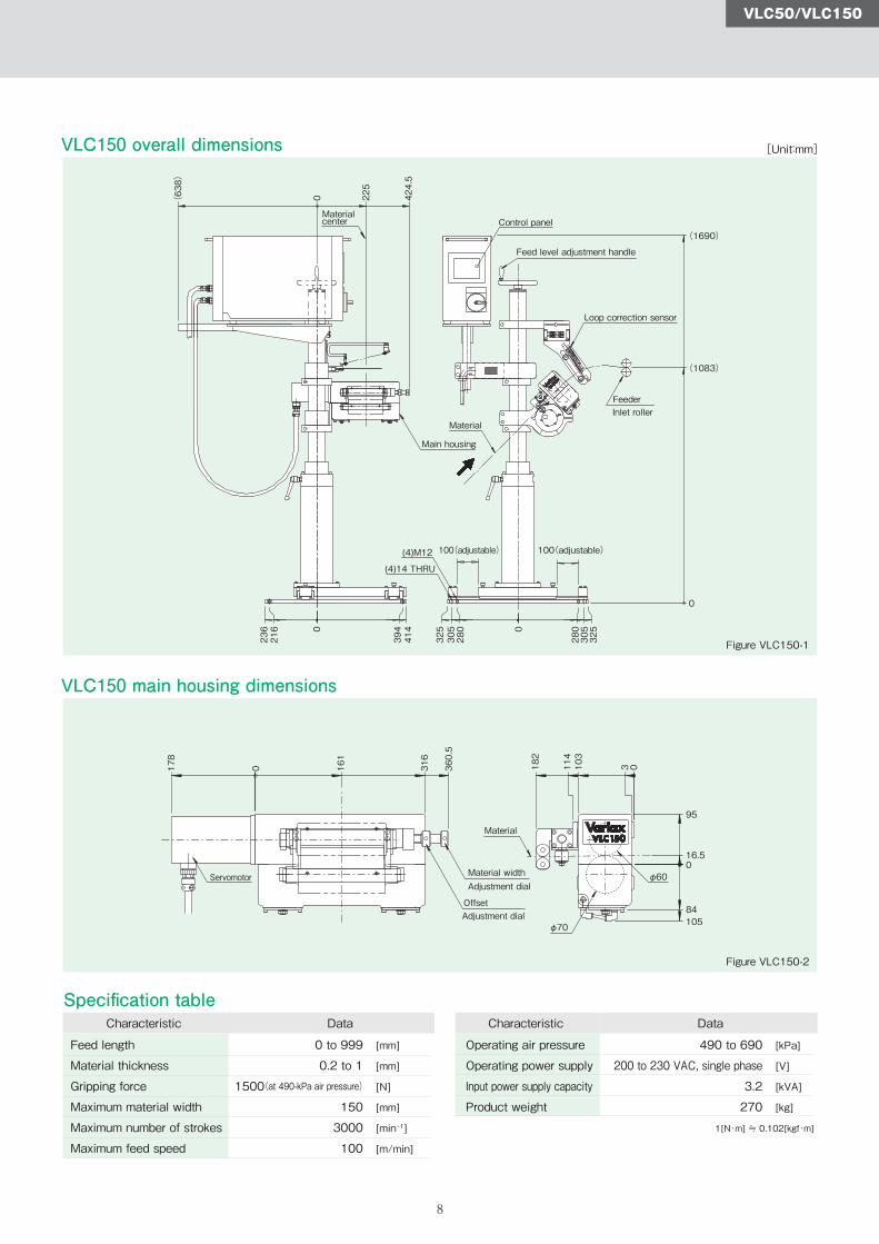
VLC150 overall dimensions
VLC150 main housing dimensions
Figure VLC150-1
Figure VLC150-2
[Unit:mm]
8
(4)M12
(4)14 THRU
Control panel(1690)
(1083)
0
Materialcenter
Feed level adjustment handle
Loop correction sensor
FeederInlet roller
Material
Main housing
100(adjustable) 100(adjustable)
Servomotor Material width
Offset
Adjustment dial
Adjustment dial
Material
(638)
0 225
424.5
236
216 0
394
414
325
305
280 0
280
305
325
178
0 161
316
360.5
182
114
103
3 0
95
16.50
84
φ60
φ70 105
VLC50/VLC150
Specification table
[kPa]
[V]
[kVA]
[kg]
1[N・m] ≒ 0.102[kgf・m]
Feed length
Material thickness
Gripping force
Maximum material width
Maximum number of strokes
Maximum feed speed
Characteristic Data Characteristic Data
[mm]
[mm]
[N]
[mm]
[min-1]
[m/min]
0 to 999
0.2 to 1
1500(at 490-kPa air pressure)
150
3000
100
490 to 690
200 to 230 VAC, single phase
3.2
270
Operating air pressure
Operating power supply
Input power supply capacity
Product weight
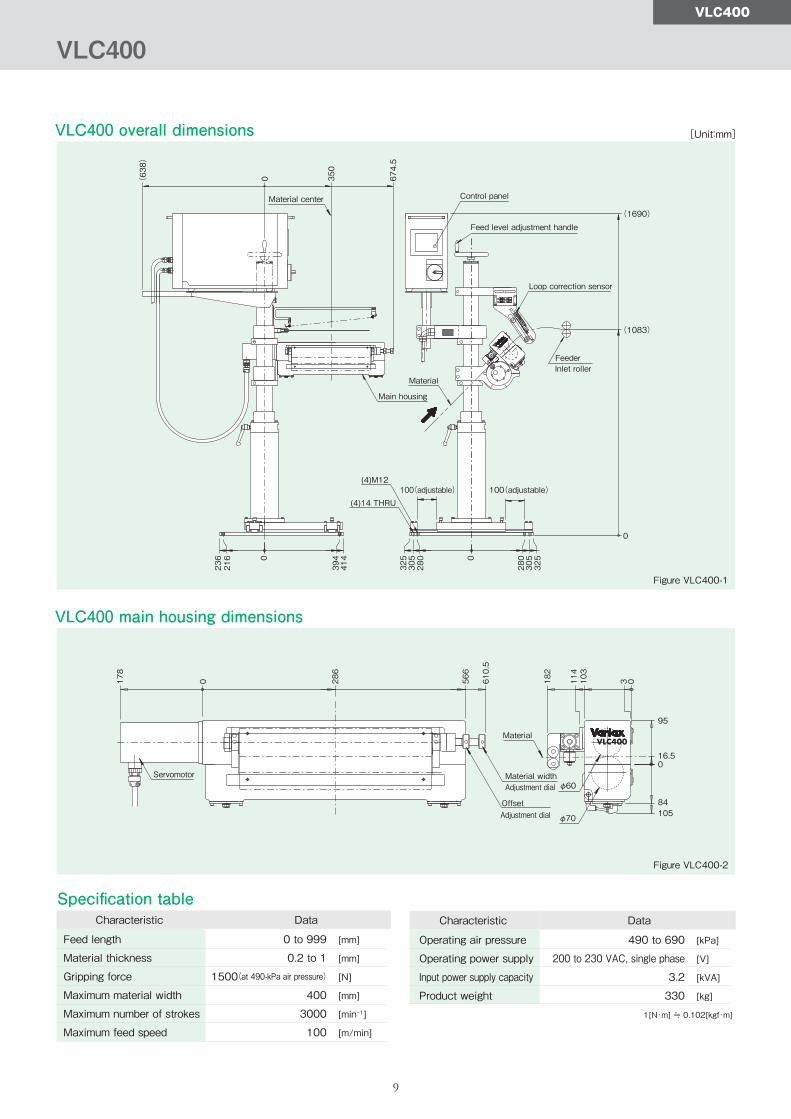
VLC400 overall dimensions
VLC400 main housing dimensions
Figure VLC400-1
Figure VLC400-2
[Unit:mm]
9
Loop correction sensor
Feed level adjustment handle
Control panel
(1690)
(1083)
0
(638)
0 350
674.5
Material center
100(adjustable) 100(adjustable)(4)M12
Main housing
Material
(4)14 THRU
Material width
Offset
Adjustment dial
Adjustment dial
Material
95
16.50
84105φ70
φ60Servomotor
FeederInlet roller
236
216 0
394
414
325
305
280 0
280
305
325
0178
286
566
610.5
182
114
103
3 0
VLC400
VLC400
Specification table
[kPa]
[V]
[kVA]
[kg]
1[N・m] ≒ 0.102[kgf・m]
Feed length
Material thickness
Gripping force
Maximum material width
Maximum number of strokes
Maximum feed speed
Characteristic Data Characteristic Data
[mm]
[mm]
[N]
[mm]
[min-1]
[m/min]
0 to 999
0.2 to 1
1500(at 490-kPa air pressure)
400
3000
100
490 to 690
200 to 230 VAC, single phase
3.2
330
Operating air pressure
Operating power supply
Input power supply capacity
Product weight

Uncoiler(VUC series)
10
Figure 10-1
Characteristic
Material width
Material thickness
Coil inner/Outer dia
Coil mass
Line speed
Drum opening/closing range
Drum open/close method
Drum turning method
Drum driving motor
Power-supply voltage
Product weight
Data
40 to 250
0.1 to 1.0
φ508×φ1350
1500(One side)
100
φ470 to φ520
Hydraulic electric type
Manual type
3kW servomotor(×2)
200 VAC three phase
1450
Units
mm
mm
mm
kg
m/min
mm
kg
Table 10-1
System configuration example
Supplies material at high speed, excellent tracking ability and stability
An unwinder with excellent high speed and tracking that we devel-oped to provide a stable material supply to our original loop control-ler. Suitable for speeding up a feed line.A servo motor is connected to the rotating part. It unwinds the coil material to supply it in real time, according to the press rotation speed.In addition, there is a swing arm that contacts the outer circumfer-ence of the coil material. It automatically measures the radius of coil material. Therefore, you can control the feeding according to the remaining amount of material, resulting in outstandingly stable operation.
UncoilerVUC series
NC Loop controllerVSC series
Servo feederVS series
Related products

Loop controller adjustment mechanismVariax VLC series and VSC series loop controllers have a mechanism for adjusting the roll height, roll tilt, sensor position and distance to the feeder.The purpose of these adjustment mechanisms is to optimize the shape of the material feed loop being sent to the feeder according to various conditions such as the size of the material to be used, the type of material, specifications such as the feed length and rotation speed, and the layout of the press line.The feeder is capable of high-speed operation by automatically adjusting settings for the feed length, material thickness, gripping force, material width, and the feed line height.As the feeder speed increases and the types of products produced increase, it becomes necessary to make the shape of the loop of material supplied to the feeder match the current conditions.If this loop shape is inappropriate, the material may bend during high speed operation and may not make usable products. Also, the material may flutter and increase the load on the feeder, resulting in misfeeding.
By using Variax's loop controller, these automatic adjustments create the optimum material loop shape, fully exploit the original capabilities of the feeder, and enable high-speed press production operation.
●Advantages of adjusting the roll height and angle of both rolls.The material loop R can be changed by changing the material thickness setting, the material and feed length settings, and the feed line height can be changed easily.
●Advantages of sensor position adjustmentThe sensor monitors the shape of the loop, and if the loop R becomes too small, it speeds up the material feed rate to the loop, increasing the loop R to maintain the optimum loop shape.If loop R gets too large, the opposite happens.If the loop shape cannot be maintained due to a problem, the system is protected by an emergency stop of the press because the loop controller is interlocked with the press.It can be set at the appropriate position for each condition, such as the size of loop R, the material feed angle, feed length, etc.
System configuration diagram
Resolver
Feeder (VS)
NC loop controllercontrol panel
Loop controller(VSC)
Crankshaft
Figure 11-1
11
Technical data
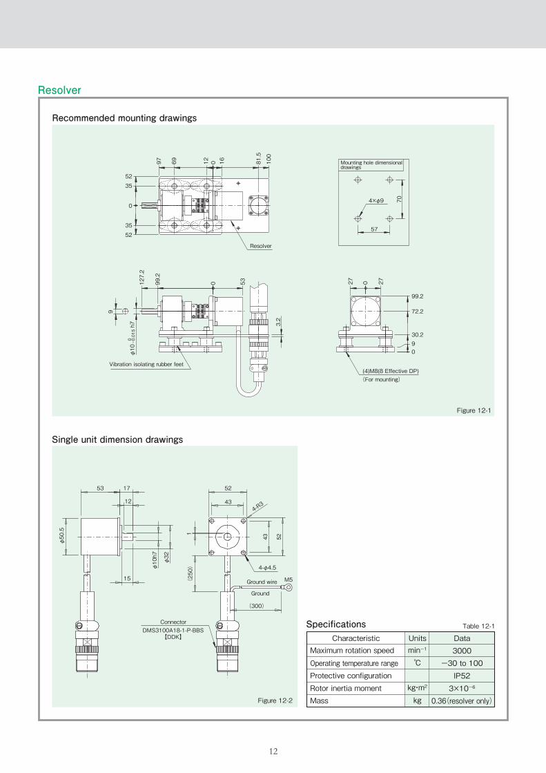
Figure 12-1
Figure 12-2
Table 12-1
Characteristic Unitsmin-1
℃
kg・m2
kg
Data3000
-30 to 100IP523×10-6
0.36(resolver only)
Resolver
Recommended mounting drawings
Single unit dimension drawings
Specifications
Resolver
52
35
0
35
52
97
127.2
99.2
0 53
3.2
9
φ10 h7
0 -0.015
69 12 0 16 81.5
100
27 0 27
704×φ9
57
99.2
72.2
30.290
Vibration isolating rubber feet(4)M8(8 Effective DP)(For mounting)
Mounting hole dimensionaldrawings
Ground wire
Ground
Connector
12
53
φ50.5
φ10h7
φ32
(250)
1
52
434-R3
17
12
15
4-φ4.5
M5
(300)
DMS3100A18-1-P-BBS【DDK】
Maximum rotation speed
Operating temperature rangeProtective configurationRotor inertia momentMass
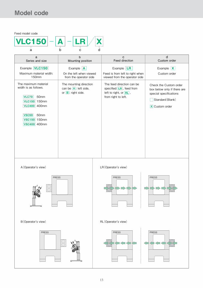
VLC150a
Ab
Feed model code
Xd
aSeries and size
bMounting position
VLC150
VLC70
Maximum material width:150mm
The maximum material width is as follows.
Example
50mmVLC150 150mmVLC400 400mm
The mounting direction can be : left side, or : right side.
A
A
On the left when viewedfrom the operator side
Example
B
X
Custom order
Example
Check the Custom order box below only if there are special specifications
Standard(Blank)
X Custom order
A(Operator's view)
VSC50 50mmVSC150 150mmVSC400 400mm
cFeed direction
dCustom order
LR
Feed is from left to right whenviewed from the operator side
Example
The feed direction can be specified: , feed from left to right, or , from right to left.
LR
RL
PRESS
LR(Operator's view)
RL(Operator's view)
PRESS PRESS
PRESS PRESS
B(Operator's view)
PRESS
LRc
13
Model code

14
Scrap cutter
Device for rotation buildup/skew
(Press machine)
Drive device
Resolver
Crankshaft
Feeder
NC loop controller
Uncoiler
A proven cam type roller feeder that has been used for many years at many press work sites, enables faster and more accurate material feeding.
A cam type gripper feeder that makes work easy and reduces setup time by enhancing various adjustment functions.
V seriesVGX series
A cam type gripper feeder that achieves high productivity with a variation that can handle any type of operation and a feed mechanism that does not mar materials.
VG series
Product system
High-performance servo feeder for upper and lower roll drive with IoT compatibility.
OPUS1 series
Scrapcutter
(Press
)
Devices forrotating
buildup die/skew deviceServo feedRoll feed
Feeder Related peripheral devicesNC loop controllerMaterial supply
Grip feedLoop
LevelerUncoiler
OPUS1 OPUS2 EVR1 EVR2
Feeder
VSC‐2020/08E(DT)
*No part of this brochure may be reproduced, transferred, or distributed without the express consent of Sankyo Seisakusho Co.*Specifications and dimensions are subject to change whithout notice. Consult Sankyo sales before ordering.*“Variax” is a registered treadmark of Sankyo Seisakusho Co. in Japan.
Mon-Fri AM8:30-12:00 PM13:00-17:30 UTC + 09:00 (JST) (Except public holidays and company holidays) Contact us
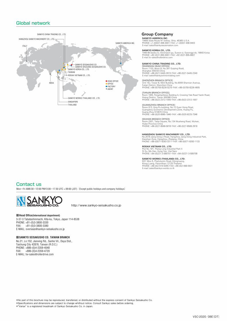
Global network
■Head Office(International department)3-37-3 Tabatashinmachi, Kita-ku, Tokyo, Japan 114-8538PHONE: +81-(0)3-3800-3330 FAX: +81-(0)3-3800-3380 E-MAIL: [email protected]
■SANKYO SEISAKUSHO CO. TAIWAN BRANCHNo.21, Ln.152, Jianxing Rd., Sanhe Vil., Daya Dist., Taichung City 42876, Taiwan (R.O.C.)PHONE: +886-(0)4-2359-4048FAX: +886-(0)4-2359-4720E-MAIL: [email protected]
http://www.sankyo-seisakusho.co.jp
Group CompanySANKYO AMERICA INC.10655 State Route 47 Sidney, Ohio, 45365 U.S.A.PHONE:+1-(0)937-498-4901・FAX:+1-(0)937-498-9403E-mail:[email protected]
SANKYO KOREA CO., LTD.1449-48 Seobu-ro, Gwonseon-gu, Suwon-si, Gyeonggi-do, 16643 KoreaPHONE:+82-(0)31-895-5991・FAX:+82-(0)31-895-6607E-mail:[email protected]
SANKYO CHINA TRADING CO., LTD.[SHANGHAI HEAD OFFICE]Room 1103, Block B, No.391 Guiping Road, Shanghai 200233 ChinaPHONE:+86-(0)21-5445-2813・FAX:+86-(0)21-5445-2340E-mail:[email protected]
RODAX VIETNAM CO., LTD.Plot No. M1, Thang Long Industrial Park IIDi Su, My Hao, Hung Yen, Viet NamPHONE:+84-(0)221-3-589701・FAX:+84-(0)221-3-589708
SANKYO WORKS (THAILAND) CO., LTD.9/31 Moo 5, Phaholyotin Road, Klongnueng, Klong Luang, Patumthani 12120 ThailandPHONE:+66-(0)2-516-5355・FAX:+66-(0)2-068-0931E-mail:[email protected]
HANGZHOU SANKYO MACHINERY CO., LTD.No.2518 Jiang Dong 2 Road, Hangzhou Jiang Dong Industrial Park,Xiaoshan Zone, Hangzhou, Zhejiang, ChinaPHONE:+86-(0)571-8283-3311・FAX:+86-(0)571-8283-1133
[SHENZHEN BRANCH OFFICE]Unit 19J, Tower B, NEO Building, No.6009 Shennan Avenue, Futian District, Shenzhen ChinaPHONE:+86-(0)755-8230-0270・FAX:+86-(0)755-8236-4605
[TIANJIN BRANCH OFFICE]Room 1905, Pengzhanfeiwo Building A, Crossing Yale Road Yaolin Road, Xiqing District, Tianjin 300380 ChinaPHONE:+86-(0)22-2312-1005・FAX:+86-(0)22-2312-1007
[GUANGZHOU BRANCH OFFICE]Room 913, Xing Pu buliding, No.12 Guan Hong Road,Guangzhou Economic Development Zone, Huang Pu, Guang Zhou 510670 ChinaPHONE:+86-(0)20-8985-1846・FAX:+86-(0)20-8225-7346
[WUHAN BRANCH OFFICE]Room 2301, Taihe Square, No.134 Wusheng Road, Wuhan, Hubei Province ChinaPHONE:+86-(0)27-8568-5818・FAX:+86-(0)27-8568-2818
RODAX VIETNAM CO., LTD.
SINGAPORE
SANKYO WORKS(THAILAND)CO., LTD.
TAIWAN
OFFICEFACTORY
HEAD OFFICE
SANKYO AMERICA INC.
AGENT
SANKYO KOREA CO., LTD.
THAILAND
INDIA
ITALY
HANGZHOU SANKYO MACHINERY CO., LTD.
SANKYO CHINA TRADING CO., LTD.
SANKYO SHIZUOKA SEISAKUSHO CO.SANKYO SEISAKUSHO CO.